US11583315B2 - Surgical access device including variable length cannula - Google Patents
Surgical access device including variable length cannulaDownload PDFInfo
- Publication number
- US11583315B2 US11583315B2US17/092,730US202017092730AUS11583315B2US 11583315 B2US11583315 B2US 11583315B2US 202017092730 AUS202017092730 AUS 202017092730AUS 11583315 B2US11583315 B2US 11583315B2
- Authority
- US
- United States
- Prior art keywords
- shaft
- surgical access
- access device
- cannula
- distal
- Prior art date
- Legal status (The legal status is an assumption and is not a legal conclusion. Google has not performed a legal analysis and makes no representation as to the accuracy of the status listed.)
- Active, expires
Links
- 239000012530fluidSubstances0.000claimsdescription41
- 230000014759maintenance of locationEffects0.000claimsdescription18
- 238000004891communicationMethods0.000claimsdescription13
- 239000013013elastic materialSubstances0.000claimsdescription3
- 241001631457CannulaSpecies0.000description8
- 210000003815abdominal wallAnatomy0.000description6
- 230000000712assemblyEffects0.000description6
- 238000000429assemblyMethods0.000description6
- 238000001356surgical procedureMethods0.000description6
- 238000000034methodMethods0.000description5
- 238000007789sealingMethods0.000description5
- 208000005646PneumoperitoneumDiseases0.000description4
- 210000000683abdominal cavityAnatomy0.000description4
- 230000003287optical effectEffects0.000description4
- 239000007789gasSubstances0.000description3
- 239000000463materialSubstances0.000description3
- 238000010276constructionMethods0.000description2
- 230000001276controlling effectEffects0.000description2
- 239000006260foamSubstances0.000description2
- 238000003780insertionMethods0.000description2
- 230000037431insertionEffects0.000description2
- 238000002357laparoscopic surgeryMethods0.000description2
- 230000013011matingEffects0.000description2
- 230000007246mechanismEffects0.000description2
- 238000012978minimally invasive surgical procedureMethods0.000description2
- 238000012986modificationMethods0.000description2
- 230000004048modificationEffects0.000description2
- 210000000056organAnatomy0.000description2
- 238000012800visualizationMethods0.000description2
- 241000405070PercophidaeSpecies0.000description1
- 210000001015abdomenAnatomy0.000description1
- 230000003187abdominal effectEffects0.000description1
- 239000000853adhesiveSubstances0.000description1
- 230000001070adhesive effectEffects0.000description1
- 230000000295complement effectEffects0.000description1
- 238000002224dissectionMethods0.000description1
- 238000002674endoscopic surgeryMethods0.000description1
- 239000000835fiberSubstances0.000description1
- 238000007373indentationMethods0.000description1
- 238000002324minimally invasive surgeryMethods0.000description1
- 239000000203mixtureSubstances0.000description1
- 230000037361pathwayEffects0.000description1
- 230000000149penetrating effectEffects0.000description1
- 230000001105regulatory effectEffects0.000description1
- 238000000926separation methodMethods0.000description1
- 238000003466weldingMethods0.000description1
Images


Classifications
- A—HUMAN NECESSITIES
- A61—MEDICAL OR VETERINARY SCIENCE; HYGIENE
- A61B—DIAGNOSIS; SURGERY; IDENTIFICATION
- A61B17/00—Surgical instruments, devices or methods
- A61B17/34—Trocars; Puncturing needles
- A61B17/3417—Details of tips or shafts, e.g. grooves, expandable, bendable; Multiple coaxial sliding cannulas, e.g. for dilating
- A61B17/3421—Cannulas
- A61B17/3423—Access ports, e.g. toroid shape introducers for instruments or hands
- A—HUMAN NECESSITIES
- A61—MEDICAL OR VETERINARY SCIENCE; HYGIENE
- A61B—DIAGNOSIS; SURGERY; IDENTIFICATION
- A61B17/00—Surgical instruments, devices or methods
- A61B17/28—Surgical forceps
- A61B17/29—Forceps for use in minimally invasive surgery
- A61B2017/2901—Details of shaft
- A61B2017/2905—Details of shaft flexible
- A—HUMAN NECESSITIES
- A61—MEDICAL OR VETERINARY SCIENCE; HYGIENE
- A61B—DIAGNOSIS; SURGERY; IDENTIFICATION
- A61B17/00—Surgical instruments, devices or methods
- A61B17/28—Surgical forceps
- A61B17/29—Forceps for use in minimally invasive surgery
- A61B2017/2901—Details of shaft
- A61B2017/2908—Multiple segments connected by articulations
- A—HUMAN NECESSITIES
- A61—MEDICAL OR VETERINARY SCIENCE; HYGIENE
- A61B—DIAGNOSIS; SURGERY; IDENTIFICATION
- A61B17/00—Surgical instruments, devices or methods
- A61B17/34—Trocars; Puncturing needles
- A61B17/3417—Details of tips or shafts, e.g. grooves, expandable, bendable; Multiple coaxial sliding cannulas, e.g. for dilating
- A61B17/3421—Cannulas
- A61B2017/3443—Cannulas with means for adjusting the length of a cannula
- A—HUMAN NECESSITIES
- A61—MEDICAL OR VETERINARY SCIENCE; HYGIENE
- A61B—DIAGNOSIS; SURGERY; IDENTIFICATION
- A61B17/00—Surgical instruments, devices or methods
- A61B17/34—Trocars; Puncturing needles
- A61B2017/348—Means for supporting the trocar against the body or retaining the trocar inside the body
- A61B2017/3482—Means for supporting the trocar against the body or retaining the trocar inside the body inside
- A61B2017/3484—Anchoring means, e.g. spreading-out umbrella-like structure
- A61B2017/3486—Balloon
Definitions
- the present disclosurerelates generally to surgical devices.
- the present disclosurerelates to a surgical access device including a cannula having a variable length to accommodate different tissue wall thicknesses.
- a surgical access devicepermits the introduction of a variety of surgical instruments into a body cavity or opening.
- a surgical access devicee.g., a cannula or an access port
- tissuee.g., a naturally occurring orifice or an incision
- the openingis typically made using an obturator having a blunt or sharp tip that may be inserted through a passageway of the surgical access device.
- a cannulahas a tube of rigid material with a thin wall construction, through which an obturator may be passed. The obturator is utilized to penetrate a body wall, such as an abdominal wall, or to introduce the surgical access device through the body wall, and is then removed to permit introduction of surgical instruments through the surgical access device to perform the surgical procedure.
- Minimally invasive surgical procedurespermit surgery to be performed on organs, tissues, and vessels far removed from an opening within the tissue.
- laparoscopic proceduresthe abdominal cavity is insufflated with an insufflation gas, e.g., CO 2 , to create a pneumoperitoneum thereby providing access to the underlying organs.
- a laparoscopic instrumentis introduced through a cannula into the abdominal cavity to perform one or more surgical tasks.
- the cannulamay incorporate a seal to establish a substantially fluid tight seal about the laparoscopic instrument to preserve the integrity of the pneumoperitoneum.
- the cannulawhich is subjected to the pressurized environment, e.g., the pneumoperitoneum, may include an inflatable anchor to prevent the cannula from backing out of the opening in the abdominal wall, for example, during withdrawal of the laparoscopic instrument from the cannula.
- Cannulasare available in different lengths and a surgeon chooses a cannula based on the thickness of the abdominal wall of a patient. Factors, such as the patient's height, weight, sex, and overall body composition provide the surgeon with information to help choose a cannula (e.g., short, standard, or long), however, abdominal wall thickness can still vary between patients with similar statistics. This may lead to opening and trying cannulas of different lengths which can add time and cost to a surgical procedure.
- Factorssuch as the patient's height, weight, sex, and overall body composition provide the surgeon with information to help choose a cannula (e.g., short, standard, or long), however, abdominal wall thickness can still vary between patients with similar statistics. This may lead to opening and trying cannulas of different lengths which can add time and cost to a surgical procedure.
- This disclosuregenerally relates to cannulas that can achieve different lengths to accommodate varying tissue wall thicknesses.
- the length of the shaft of the cannulais adjustable so that the cannula can be customized to each individual patient. This adjustability allows a surgeon to set the length of the cannula based on patient need.
- the variable length cannulaas compared to a fixed length cannula, is universal and may reduce the number of types of cannulas needed in a hospital, save a surgeon the difficulty of choosing a cannula having an optimal length for a particular patient, and/or minimize the need to open multiple cannulas if the incorrect length is chosen.
- variable length cannula of the present disclosuremay also include fixation mechanisms for securing the cannula within tissue regardless of the chosen shaft length.
- the cannulamay include an inflatable balloon and/or a retention collar to provide fixation on one and/or both sides of a tissue wall (e.g., fixation in one or two directions during instrument removal and/or insertion), and/or may include grips on an outer surface of the shaft that engage the opening in the tissue wall to aid in fixation within the tissue.
- the disclosureprovides a surgical access device including a cannula having a shaft assembly including an outer shaft, an intermediate shaft disposed within and longitudinal slidable relative to the outer shaft, and an inner shaft disposed within and longitudinal slidable relative to the intermediate shaft.
- the shaft assemblyis movable between an unextended position, a fully extended position, and a semi-extended position between the unextended and fully extended positions.
- the inner shaftmay be movable within the intermediate shaft between a proximal-most position and a distal-most position and the intermediate shaft may be movable within the outer shaft between a proximal-most position and a distal-most position.
- the inner and intermediate shaftsWhen the shaft assembly is in the unextended position, the inner and intermediate shafts may be in the proximal-most positions, when the shaft assembly is in the fully extended position, the inner and intermediate shafts may be in the distal-most positions, and when the shaft assembly is in the semi-extended position, the inner shaft may be in the proximal-most position and the intermediate shaft may be in the distal-most position.
- a distal end portion of the outer shaftmay include an annular ridge on an inner surface thereof and the intermediate shaft may include proximal and distal annular grooves defined in an outer surface thereof.
- the annular ridge of the outer shaftmay be engaged with the distal annular groove of the intermediate shaft and when the shaft assembly is in the semi-extended and fully extended positions, the annular ridge of the outer shaft may be engaged with the proximal annular groove of the intermediate shaft.
- a distal end portion of the intermediate shaftmay include an annular ridge on an inner surface thereof and the inner shaft may include proximal and distal annular grooves defined in an outer surface thereof.
- the annular ridge of the intermediate shaftmay be engaged with the distal annular groove of the inner shaft and when the shaft assembly is in the fully extended position, the annular ridge of the intermediate shaft may be engaged with the proximal annular groove of the inner shaft.
- a first gasketmay be disposed between the intermediate and outer shafts and a second gasket may be disposed between the inner and intermediate shafts.
- the surgical access devicemay further include a balloon operably associated with the cannula.
- a proximal portion of the balloonmay be secured to the outer shaft of the shaft assembly and a distal portion of the balloon may be secured to the inner shaft of the shaft assembly.
- An inflation channelmay be defined in an outer surface of the outer shaft of the shaft assembly and in fluid communication with the balloon.
- the surgical access devicemay further include an anchor inflation port coupled to the outer shaft of the shaft assembly and in fluid communication with the inflation channel of the outer shaft.
- the surgical access devicemay further include an instrument housing coupled to the cannula.
- the instrument housingmay be secured to the outer shaft of the shaft assembly of the cannula.
- the surgical access devicemay further include a retention collar movably positioned along the shaft assembly of the cannula.
- the disclosureprovides a surgical access device including a cannula having a shaft defining an access lumen therethrough.
- the shafthas annular folds formed therein.
- the annular foldsare axially movable relative to each other such that the shaft is longitudinally movable between an unextended position and a plurality of extended positions.
- the annular foldsmay be formed in a central portion of the shaft.
- the central portion of the shaftmay extend a majority length of the shaft.
- the shaftmay include proximal and distal end portions having fixed lengths.
- the annular foldsmay include alternating inner and outer fold peaks.
- the outer fold peaksmay be spaced a first axial distance relative to each other when the shaft is in the unextended position and a second axial distance relative to each other when in the shaft is in one of the plurality of extended positions.
- the second axial distancemay be greater than the first axial distance.
- the outer fold peaksmay be pointed for tissue fixation.
- the surgical access devicemay further include an instrument housing coupled to the cannula.
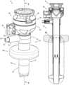
- FIG. 1is a perspective view of a surgical access assembly including a surgical access device in accordance with an aspect of the disclosure, shown with a cannula of the surgical access device in an unextended position;
- FIG. 2is an exploded view of the surgical access assembly of FIG. 1 ;
- FIG. 3is cross-sectional view of the surgical access assembly of FIG. 1 , taken along section line 3 - 3 of FIG. 1 ;
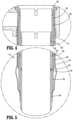
- FIG. 4is a close-up view of the area of detail indicated in FIG. 3 ;
- FIG. 5is a close-up view of the area of detail indicated in FIG. 3 ;
- FIG. 6is a perspective view of the surgical access assembly of FIG. 1 , shown secured to tissue;
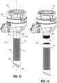
- FIG. 7is a perspective view of the surgical access assembly of FIG. 1 , shown with the cannula in a partially extended position and secured to tissue;
- FIG. 8is a cross-sectional view of the surgical access assembly of FIG. 7 , taken along section line 8 - 8 of FIG. 7 ;
- FIG. 9is a close-up view of the area of detail indicated in FIG. 8 ;
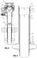
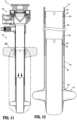
- FIG. 10is a perspective view of the surgical access assembly of FIG. 1 , shown with the cannula in a fully extended position and secured to tissue;
- FIG. 11is a cross-sectional view of the surgical access assembly of FIG. 10 , taken along section line 11 - 11 of FIG. 10 ;
- FIG. 12is a close-up view of the area of detail indicated in FIG. 11 ;
- FIG. 13is a perspective view of a surgical access device in accordance with another aspect of the present disclosure, shown with a cannula of the surgical access device in an unextended state;
- FIG. 14is a perspective view of the surgical access device of FIG. 13 , shown with the cannula separated from an instrument housing of the surgical access device;
- FIG. 15is a cross-sectional view of the surgical access device of FIG. 13 , taken along section line 15 - 15 of FIG. 13 ;
- FIG. 16is a close-up view of the area of detail indicated in FIG. 15 ;
- FIG. 17is a perspective view of the surgical access device of FIG. 13 , shown with the cannula in an extended state;
- FIG. 18is a cross-sectional view of the surgical access device of FIG. 17 , taken along section line 18 - 18 of FIG. 17 .
- proximalrefers to a portion of a structure, or component thereof, that is closer to a user
- distalrefers to a portion of the structure, or component thereof, that is farther from the user.
- Surgical access assemblies with obturatorsare employed during minimally invasive surgery, e.g., laparoscopic surgery, and provide for the sealed access of surgical instruments into an insufflated body cavity, such as the abdominal cavity.
- the surgical access assemblies of the present disclosureinclude a surgical access device having an instrument housing mounted on a cannula.
- An obturator(not shown) is insertable through the instrument housing and the cannula.
- the obturatorcan have a blunt distal end, or a bladed or non-bladed penetrating distal end, and can be used to incise and/or separate tissue of the abdominal wall so that the surgical access assembly can be introduced into the abdomen.
- the handle of the obturatorcan engage or selectively lock into the instrument housing of the surgical access device.
- a bladeless optical trocar obturatormay be provided that permits separation of tissue planes in a surgical procedure and visualization of body tissue fibers as they are being separated, thereby permitting a controlled traversal across a body wall.
- the trocar obturatormay be bladeless without being optical, e.g., without providing contemporaneous visualization thereof through the distal tip of the trocar obturator.
- the bladeless trocar obturatormay be provided for the blunt dissection of the abdominal lining during a surgical procedure.
- Trocar obturators suitable for use with the surgical access devices of the present disclosureare known and include, for example, bladed, bladeless, blunt, optical, and non-optical.
- exemplary trocar assembliesincluding exemplar trocar obturators, reference may be made to PCT Publication No. WO 2016/186905, the entire content of which is hereby incorporated by reference herein.
- FIGS. 1 - 3illustrates a surgical access assembly 10 including a surgical access device 100 and a retention collar 180 supported on the surgical access device 100 .
- the surgical access assembly 10will further be described to the extent necessary to disclose aspects of the disclosure.
- exemplary surgical access assembliesincluding exemplar surgical access devices and exemplar retention collars, reference may be made to U.S. Pat. Nos. 7,300,448; 7,691,089; and 8,926,508, the entire content of each of which is hereby incorporated by reference herein. Accordingly, it should be understood that a variety of surgical access assemblies and devices may utilize the variable length cannula of the present disclosure.
- the surgical access device 100includes a cannula 110 and an instrument housing 150 secured to the cannula 110 .
- the cannula 110generally includes a shaft assembly 112 extending along a longitudinal axis “X” and defining an access lumen 111 for reception and passage of a surgical instrument (not shown) therethrough.
- the shaft assembly 112includes an outer shaft or first shaft segment 120 , an intermediate shaft or second shaft segment 130 , and an inner shaft or third shaft segment 140 .
- the outer, intermediate, and inner shafts 120 , 130 , 140are coaxial and telescopically mated so that the shaft assembly 112 is movable between an unextended position ( FIG. 6 ), a semi-extended position ( FIG. 7 ), and a fully extended position ( FIG. 10 ), as described in further detail below.
- the outer shaft 120includes an elongated body 122 having a generally cylindrical shape and including an outer surface 122 a and an inner surface 122 b (shown in phantom).
- An inflation channel 121is defined in the outer surface 122 a of the elongated body 122 and extends longitudinally along a length thereof.
- the inflation channel 121may extend along a majority of the length of the elongated body 122 from a proximal end portion 120 a to a distal end portion 120 b of the outer shaft 120 .
- the proximal end portion 120 a of the outer shaft 120supports the instrument housing 150 thereon such that the outer shaft 120 is secured to, and longitudinally fixed relative to, the instrument housing 150 .
- the distal end portion 120 b of the outer shaft 120includes an annular ridge 124 (shown in phantom) on the inner surface 122 b of the elongated body 122 .
- the annular ridge 124is raised relative to the inner surface 122 b and extends into the access lumen 111 .
- the annular ridge 124may be in the form of a rib, band, bump, or other protrusion within the purview of those skilled in the art.
- the annular ridge 124is integrally formed within the outer shaft 120 and, in some other aspects, the annular ridge 124 is a separate component, such as a rubber gasket or other mechanical interface that is secured (e.g., overmolded) to the outer shaft 120 .
- the intermediate shaft 130includes an elongated body 132 having a generally cylindrical shape and including an outer surface 132 a and an inner surface 132 b (shown in phantom).
- the outer surface 132 a of the elongated body 132is sized to closely fit the inner surface 122 b of the outer shaft 120 and is configured to be slidably disposed therein.
- a proximal end portion 130 a of the intermediate shaft 130includes a proximally extending collar 136 defining an annular recess 137 in an outer surface thereof.
- the annular recess 137is configured to receive a gasket 138 therein for sealing engagement between the intermediate shaft 130 and the outer shaft 120 .
- the collar 136may have first and second collar sections 136 a , 136 b that allow the collar 136 to flex, which, together, with the gasket 138 , maintains a fluid tight seal between the intermediate shaft 130 and the outer shaft 120 while allowing a little give during movement of the intermediate shaft 130 relative to the outer shaft 120 .
- a proximal annular groove 133is defined in the outer surface 132 a of the elongated body 132 distal to the collar 136 in the proximal end portion 130 a of the intermediate shaft 130 and a distal annular groove 135 is defined in the outer surface 132 a of the elongated body 132 in the distal end portion 130 b of the intermediate shaft 130 .
- the proximal and distal annular grooves 133 , 135are sized and shaped to receive the annular ridge 124 of the outer shaft 120 therein to limit travel of the intermediate shaft 130 relative to the outer shaft 120 .
- the annular ridge 124achieves a seal between the outer shaft 120 and the intermediate shaft 130 when the annular ridge 124 is engaged with the proximal or distal annular groove 133 , 135 .
- the distal end portion 130 b of the intermediate shaft 130also includes an annular ridge 134 (shown in phantom) on the inner surface 132 b of the elongated body 132 .
- the inner shaft 140includes an elongated body 142 having a generally cylindrical shape and including an outer surface 142 a and an inner surface 142 b (shown in phantom).
- the elongated body 142is sized to closely fit the inner surface 132 b of the elongated body 132 of the intermediate shaft 130 and is configured to be slidably disposed therein.
- a proximal end portion 140 a of the inner shaft 140includes a proximally extending collar 146 defining an annular recess 147 in an outer surface thereof.
- the annular recess 147is configured to receive a gasket 148 therein for sealing engagement between the inner shaft 140 and the intermediate shaft 130 .
- the collar 146may have first and second collar sections 146 a , 146 b that allow the collar 146 to flex, which, together, with the gasket 148 , maintains a fluid tight seal between the inner shaft 140 and the intermediate shaft 130 while allowing a little give during movement of the inner shaft 140 relative to the intermediate shaft 130 .
- a proximal annular groove 143is defined in the outer surface 142 a of the elongated body 142 distal to the collar 146 in the proximal end portion 140 a of the inner shaft 140 and a distal annular groove 145 is defined in the outer surface 142 a of the elongated body 142 in the distal end portion 140 b of the inner shaft 140 .
- the proximal and distal annular grooves 143 , 145are sized and shaped to receive the annular ridge 134 of the intermediate shaft 130 therein to limit travel of the inner shaft 140 relative to the intermediate shaft 130 .
- the annular ridge 134achieves a seal between the intermediate shaft 130 and the inner shaft 140 when the annular ridge 134 is engaged with the proximal or distal annular groove 143 , 145 .
- the cannula 110further includes a balloon 114 operably associated with the shaft assembly 112 .
- the balloon 114includes a sleeve 116 and an expandable anchor 118 .
- the expandable anchor 118secures the cannula 110 against an inner surface of a body wall (see e.g., FIG. 6 ).
- the balloon 114is positioned around the shaft assembly 112 with a proximal portion 114 a of the balloon 114 secured to the proximal end portion 120 a of the outer shaft 120 and a distal portion 114 b of the balloon 114 secured to the distal end portion 140 b of the inner shaft 140 .
- the proximal portion 114 a of the balloon 114is secured to the outer shaft 120 at a location distal to a proximal end portion 121 a of the inflation channel 121 and the distal portion 114 b of the balloon 114 is secured to the inner shaft 140 at a location distal to the distal annular groove 145 .
- the balloon 114is secured to the outer and inner shafts 120 , 140 (e.g., by adhesives and/or welding) to create hermetic contact therebetween.
- the sleeve 116is positioned distal to the proximal end portion 121 a of the inflation channel 121 defined in the outer shaft 120 of the shaft assembly 112 so that the inflation channel 121 is open to fluid communication with a fluid source (not shown) and the expandable anchor 118 is positioned distal to a distal end portion 121 b of the inflation channel 121 so that the expandable anchor 118 is in fluid communication with the inflation channel 121 .
- the shape and diameter of the balloon 114remains relatively constant regardless of the length of the shaft assembly 112 .
- the balloon 114has a length that is the length of the shaft assembly 112 when the shaft assembly 112 is disposed in the fully extended position ( FIG. 10 ).
- the sleeve 118 of the balloon 114may fold together or bunch up when the shaft assembly 112 is in the unextended position ( FIG. 6 ) or the semi-extended position ( FIG. 7 ).
- the balloon 114is formed from a highly elastic material and has a length that is less than the length of the shaft assembly 112 when the shaft assembly 112 is in the fully extended position.
- the balloon 114can stretch to accommodate the shaft assembly 112 when the shaft assembly 112 is in the fully extended position.
- the instrument housing 150includes an upper housing section 152 and a lower housing section 154 , and defines a cavity 151 therein that communicates with the access lumen 111 of the shaft assembly 112 of the cannula 110 .
- the upper housing section 152may be selectively attachable to, and detachable from, the lower housing section 154 , and the lower housing section 154 may be releasably or permanently attached to the outer shaft 120 of the shaft assembly 112 of the cannula 110 .
- either or both of the upper and lower housing sections 152 , 154 of the instrument housing 150may include knurls, indentations, tabs, or be otherwise configured to facilitate engagement by a user.
- the instrument housing 150supports a seal assembly 156 and a valve assembly 158 therein.
- the seal assembly 156is disposed proximally of the valve assembly 158 .
- the seal assembly 156generally includes an instrument seal 156 a for sealing around surgical instruments (not shown) inserted into the cannula 110
- the valve assembly 158generally includes a zero-closure seal 158 a for sealing the access lumen 111 of the cannula 110 in the absence of a surgical instrument inserted through the cannula 110 .
- the seal assembly 156 and the valve assembly 158prevent the escape of the insufflation fluid therefrom, while allowing surgical instruments to be inserted therethrough and into the body cavity.
- the instrument seal 156 amay include any known instrument seal used in cannulas and/or trocars, such as septum seal.
- the zero-closure seal 158 amay be any known zero-closure seal for closing off the passageway into the access lumen 111 , such as a duckbill seal or flapper valve.
- the instrument housing 150includes an insufflation port 160 coupled to the lower housing section 154 .
- the insufflation port 160defines an opening 161 therethrough that is in fluid communication with the cavity 151 of the instrument housing 150 which, in turn, is in fluid communication with the access lumen 111 of the cannula 110 to insufflate a body cavity, such as abdominal cavity (e.g., create a pneumoperitoneum).
- the opening 161 of the insufflation port 160is disposed distally of the valve assembly 158 to maintain insufflation pressure within the body cavity.
- the insufflation port 160is connectable to a source of insufflation fluid (not shown) for delivery of the insufflation fluid (e.g., gases) into the body cavity.
- the insufflation port 160is configured and dimensioned to receive a valve 162 in a substantially fluid-tight manner.
- the valve 162is a stopcock valve for controlling the flow of the insufflation fluid.
- the valve 162may be any known valve for directing fluid flow and, in some aspects, regulating fluid flow.
- the surgical access device 100includes an anchor inflation port 170 coupled to the outer shaft 120 of the shaft assembly 112 of the cannula 110 .
- the anchor inflation port 170includes a housing 172 and a collar 174 extending from the housing 172 .
- the collar 174secures the housing 172 to the outer shaft 120 of the shaft assembly 112 .
- the collar 174extends around the outer shaft 120 and is engaged with the outer shaft 120 in a manner that fixes (e.g., longitudinally and rotationally) the anchor inflation port 170 relative to the shaft assembly 112 . More particularly, the collar 174 may be engaged with the outer shaft 120 of the shaft assembly 112 by snap fit connection or in a friction fit manner. It should be understood that other mating structures and relationships may be utilized to secure the anchor inflation port 170 to the outer shaft 120 of the shaft assembly 112 .
- the anchor inflation port 170is in fluid communication with the expandable anchor 118 of balloon 114 .
- the housing 172 of the anchor inflation port 170defines a cavity 171 therein that is in fluid communication with inflation channel 121 of the outer shaft 120 of the cannula 110 which, in turn, is in fluid communication with the expandable anchor 118 of the balloon 114 .
- the housing 172is connectable to a fluid source (not shown) for delivery of a fluid (e.g., gases) into the expandable anchor 118 .
- the anchor inflation port 170includes a valve 176 operably coupled to the housing 172 in a substantially fluid-tight manner.
- the valve 176is a check valve that allows the fluid to flow into the expandable anchor 118 and prevents reverse flow of the fluid therefrom.
- the valve 176may be any known valve for controlling fluid flow.
- the anchor inflation port 170may further include a release valve (not shown) to allow the escape of fluid from the expandable anchor 118 and/or limit pressure that can build up in the expandable anchor 118 .
- the inflation channel 121 defined in the outer shaft 120provides a pathway for fluid flow from the fluid source (not shown) to the expandable anchor 118 .
- the proximal end 121 a of the inflation channel 121is disposed within the cavity 171 of the housing 172 of the anchor inflation port 170 and in fluid communication therewith to provide an inlet from the fluid source (not shown) during inflation and an outlet into the cavity 171 during deflation.
- the distal end 121 b of the inflation channel 121is disposed within or adjacent to the expandable anchor 118 and is in fluid communication therewith to provide an inlet into the expandable anchor 118 during inflation and an outlet from the expandable anchor 118 during deflation.
- a fluid source(not shown) is releasably attached to the anchor inflation port 170 and pressurized fluid is introduced into the anchor inflation port 170 , through the inflation channel 121 , and into the expandable anchor 118 causing the expandable anchor 118 to expand.
- the valve 176 of the anchor inflation port 170may be actuated to depressurize the fluid and allow it to escape therethrough causing the expandable anchor 118 to retract or collapse.
- the retention collar 180is supported on the shaft assembly 112 of the cannula 110 .
- the retention collar 180includes an annular body 182 having an opening 183 defined therethrough that is sized and shaped to accommodate the shaft assembly 112 of the cannula 110 therein.
- the retention collar 180is releasably engageable with shaft assembly 112 , and slidable therealong to adjust the longitudinal position of the retention collar 180 on the shaft assembly 112 .
- the retention collar 180is configured to frictionally engage any of the outer, intermediate, and inner shafts 120 , 130 , 140 of the shaft assembly 112 to limit movement of the retention collar 180 relative to the cannula 110 and to secure the cannula 110 against an outer surface of a body wall (see e.g., FIG. 6 ).
- the retention collar 180may be formed from a compressible material (e.g., foam) to aid in sealing the opening into the tissue of the body wall.
- the retention collar 180may include any known retention mechanism used on cannulas and/or trocars, such as foam collars.
- FIGS. 3 - 5the surgical access assembly 10 is shown with the shaft assembly 112 of the cannula 110 in an unextended position and the balloon 114 deflated.
- the cannula 110is at its shortest length with the inner shaft 140 disposed within the intermediate shaft 130 in a proximal-most position and the intermediate shaft 130 disposed within the outer shaft 120 in a proximal-most position.
- the distal end portion 130 b of the intermediate shaft 130extends distally beyond the distal end portion 120 b of the outer shaft 120
- the distal end portion 140 b of the inner shaft 140extends distally beyond the distal end portion 130 b of the intermediate shaft 130 .
- the proximal annular grooves 133 , 143 of the intermediate and inner shafts 130 , 140are free and not engaged or mated with any structure of the outer or intermediate shafts 120 , 130 , respectively.
- the distal annular grooves 135 , 145 of the intermediate and inner shafts 130 , 140are engaged with the annular ridges 124 , 134 of the outer and intermediate shafts 120 , 130 , respectively, to retain the shaft assembly 112 in the unextended position.
- the distal annular groove 135 of the intermediate shaft 130mates with the annular ridge 124 of the outer shaft 120
- the distal annular groove 145 of the inner shaft 140mates with the annular ridge 134 of the intermediate shaft 130 .
- FIG. 6illustrates the surgical access assembly 10 disposed within tissue “T 1 ,” e.g., an abdominal wall, with the cannula 110 in the unextended position.
- the shaft assembly 112 of the cannula 110is received through the tissue “T 1 ” (e.g., by utilizing an obturator (not shown) to facilitate entry of the cannula 110 through the tissue “T 1 ”), and the expandable anchor 118 of the balloon 114 is inflated within a body cavity “C” to prevent the cannula 110 from being withdrawn through the tissue “T 1 .”
- the expandable anchor 118is inflated by introducing fluid from a fluid source (not shown) into the valve 176 of the anchor inflation port 170 , through the inflation channel 121 ( FIG.
- the retention collar 180is slid distally along the shaft assembly 112 (e.g., the outer shaft 120 ) of the cannula 110 until the retention collar 180 abuts or presses on the tissue “T 1 .”
- the tissue “T 1 ”is thus sandwiched between the expandable anchor 118 and the retention collar 180 to prevent the cannula 110 from being withdrawn from or over-inserted into the tissue “T 1 .”
- the surgical access assembly 10is secured to the tissue “T 1 ” and longitudinal movement of the cannula 110 relative to the tissue “T 1 ” is prevented or minimized throughout insertion, withdrawal, and/or manipulation of a surgical instrument (not shown) through the cannula 110 .
- the expandable anchor 118is deflated to permit the withdrawal of the surgical access assembly 10 from the tissue “T 1 .”
- the cannula 110is moved to a semi-extended or partially extended position for positioning within tissue “T 2 ” that is thicker than tissue “T 1 ” ( FIG. 6 ).
- the surgical access assembly 10is used in the same manner as described above with regard to tissue “T 1 ”, however, the pressure of the fluid from the fluid source into the anchor inflation port 170 is increased to move the shaft assembly 112 distally from the unextended position to the semi-extended position. Alternatively, the shaft assembly 112 may be moved to the semi-extended position manually.
- the intermediate shaft 130is moved distally relative to the outer shaft 120 such that the distal annular groove 135 of the intermediate shaft 130 disengages from the annular ridge 124 of the outer shaft 120 and is free.
- the intermediate shaft 130slides distally until the proximal annular groove 133 engages and mates with the annular ridge 124 of the outer shaft 120 .
- the intermediate shaft 130is disposed within the inner shaft 120 in a distal-most position and the inner shaft 140 remains in the same position relative to the intermediate shaft 130 as when in the unextended position (e.g., the proximal-most position) with the proximal annular groove 143 of the inner shaft 140 free from engagement and the distal annular groove 145 engaged with the annular ridge 134 of the intermediate shaft 130 .
- the cannula 110is moved to an extended or fully extended position for positioning within tissue “T 3 ” that is thicker than tissue “T 2 ” ( FIG. 7 ).
- the surgical access assembly 10is used in the same manner as described above with regard to tissues “T 1 ” and “T 2 ”, however, the pressure of the fluid from the fluid source into the anchor inflation port 170 is increased to move the shaft assembly 112 distally to the fully extended position. Alternatively, the shaft assembly 112 may be moved to the fully extended position manually.
- the inner shaft 140is moved distally relative to the intermediate shaft 130 such that the distal annular groove 145 of the inner shaft 140 disengages the annular ridge 134 of the intermediate shaft 130 and is free.
- the inner shaft 140slides distally until the proximal annular groove 143 engage and mates with the annular ridge 134 of the intermediate shaft 130 .
- the inner shaft 140is disposed within the intermediate shaft 130 in a distal-most position and the intermediate shaft 140 remains in the same position relative to the outer shaft 120 as when in the semi-extended position (e.g., the distal-most position) with the proximal annular groove 133 engaged with the annular ridge 124 of the outer shaft 120 and the distal annular groove 135 free from engagement.
- the shaft assembly 112is also movable to a plurality of partially extended positions via frictional engagement of the gaskets 138 , 148 with the inner surfaces 122 b , 132 b of the outer and intermediate shafts 120 , 130 , respectively.
- the gasket 138may hold the intermediate shaft 130 relative to the outer shaft 120 in a plurality of partially extended positions between the unexpanded and semi-expanded positions and the gasket 148 may hold the inner shaft 140 relative to the intermediate shaft 130 in a plurality of partially extended positions between the semi-expanded and fully expanded positions.
- outer, intermediate, and inner shafts 120 , 130 , 140are shown as being substantially circular cylinders, it should be understood that they may be any shape telescopically arranged and slidable relative to each other (e.g., elliptical cylinders).
- annular ridges 124 , 134 , the proximal annular grooves 133 , 143 , and the distal annular grooves 135 , 145are shown as continuous ridges and grooves extending completely around the respective shaft segments, it should be understood that the ridges and grooves may be discontinuous (e.g., extend partially around the respective shaft segments) so long as the ridges and grooves are complementary and configured to mate with each other.
- intermediate and inner shafts 130 , 140are shown as including proximal annular grooves 133 , 143 and distal annular grooves 135 , 145 , it should be understood that the intermediate shaft and/or the inner shaft may include additional grooves to accommodate additional lengths of the shaft assembly 112 .
- the lengths of the outer, intermediate, and inner shafts 120 , 130 , 140are shown as being substantially the same, it should be understood that the lengths of the shaft segments may vary (e.g., the outer shaft may be longer than the intermediate shaft and/or the inner shaft).
- shaft assembly 112is shown including three shaft segments, it should be understood that the shaft assembly may include two shaft segments (e.g., an outer shaft and an inner shaft) or more than three shaft segments (e.g., an outer shaft, two or more intermediate shafts, and an inner shaft).
- the surgical access device 200includes a cannula 210 and an instrument housing 250 .
- the cannula 210includes a shaft 212 extending along a longitudinal axis “X” and defining an access lumen 211 for reception and passage of a surgical instrument (not shown) therethrough.
- the shaft 212includes proximal and distal end portions 212 a , 212 b having fixed lengths and a central portion 212 c having a variable length.
- the central portion 212 cincludes a plurality of annular folds 213 , in the manner of an accordion, formed therein such that the shaft 212 is movable between an unextended position to a fully extended position, as well as a multitude of partially extended positions therebetween, as described in further detail below.
- the shaft 212is formed from a material that is substantially rigid so as to hold the shape of the shaft 212 yet flexible to allow for length adjustment (e.g., extension or retraction of the annular folds 213 ).
- the shaft 212may be molded so that the shaft 212 can be extended or retracted similar to an accordion.
- a proximal end portion 210 a of the cannula 210supports the instrument housing 250 thereon.
- the proximal end portion 210 a of the cannula 210includes a threaded inner surface 215 that is configured to mate with a threaded outer surface 255 of the instrument housing 250 .
- other mating structures and/or attachment methodsmay be utilized to secure the instrument housing 250 to the cannula 210 or the instrument housing 250 and the cannula 210 may be integrally formed.
- the instrument housing 250is otherwise substantially the same as instrument housing 150 (e.g., the instrument housing 250 includes upper and lower housing sections, a seal assembly, a valve assembly, and an insufflation port).
- the annular folds 213extend circumferentially around the shaft 212 such that the central portion 212 c can be longitudinally extended or retracted.
- the annular folds 213are formed with oppositely directed and alternating inner and outer fold peaks 213 a , 213 b .
- the outer fold peaks 213 bmay be pointed (e.g., sharp or spiked) to provide grips for tissue fixation.
- adjacent outer fold peaks 213 bare spaced an axial distance “x 1 ” relative to each other.
- the shaft 212may be moved to an extended position in which the annular folds 213 move axially apart to accommodate a longer length of the central portion 212 c such that adjacent outer fold peaks 213 b are spaced an axial distance “x 2 ” relative to each other.
- the axial distance “x 2 ”is greater than the axial distance “x 1 ” ( FIG. 16 ).
- the central portion 212 c of the elongated body 212may be retracted by axially pushing the annular folds 213 closer together (e.g., in an overlapping configuration) to create the shortest possible length of the shaft 212 and expanded by axially pulling the annular folds 213 apart to create a longer length.
- the length of the shaft 212may be selected to accommodate the thickness of a tissue wall.
- the shaft 212 of the cannula 210is inserted into tissue in a fully extended position so that an obturator (not shown) can be used without needing to accommodate multiple length cannulas. Once inserted into the tissue, the shaft 212 can be retracted to set the optimal length of the cannula 210 for the tissue wall.
- the cannula 210is shown including the annular folds 213 along a majority of the length of the shaft 212 , it should be understood that the annular folds 213 may be provided in a portion of the length of the elongated shaft.
- the annular folds 213may be provided in a distal half of the shaft 212 and a retention collar 180 ( FIG. 1 ) may be utilized with the surgical access device 200 for added fixation.
- the surgical access device 200may include a balloon for advanced fixation.
- the surgical access device 200may include an anchor inflation port 170 ( FIG. 1 ) coupled to the proximal end portion 212 a of the shaft 212 and an expandable anchor 118 ( FIG.
- an inflation lumen(not shown) extending between the anchor inflation port and the expandable anchor (e.g., a tube extending through the access lumen of the cannula).
Landscapes
- Health & Medical Sciences (AREA)
- Surgery (AREA)
- Life Sciences & Earth Sciences (AREA)
- Biomedical Technology (AREA)
- Nuclear Medicine, Radiotherapy & Molecular Imaging (AREA)
- Engineering & Computer Science (AREA)
- Pathology (AREA)
- Heart & Thoracic Surgery (AREA)
- Medical Informatics (AREA)
- Molecular Biology (AREA)
- Animal Behavior & Ethology (AREA)
- General Health & Medical Sciences (AREA)
- Public Health (AREA)
- Veterinary Medicine (AREA)
- Surgical Instruments (AREA)
Abstract
Description
Claims (20)
Priority Applications (5)
| Application Number | Priority Date | Filing Date | Title |
|---|---|---|---|
| US17/092,730US11583315B2 (en) | 2020-11-09 | 2020-11-09 | Surgical access device including variable length cannula |
| PCT/US2021/057667WO2022098622A1 (en) | 2020-11-09 | 2021-11-02 | Surgical access device including variable length cannula |
| CN202180075245.9ACN116528781A (en) | 2020-11-09 | 2021-11-02 | Surgical access device including a variable length cannula |
| EP21816585.0AEP4240259A1 (en) | 2020-11-09 | 2021-11-02 | Surgical access device including variable length cannula |
| US18/111,987US20230200848A1 (en) | 2020-11-09 | 2023-02-21 | Surgical access device including variable length cannula |
Applications Claiming Priority (1)
| Application Number | Priority Date | Filing Date | Title |
|---|---|---|---|
| US17/092,730US11583315B2 (en) | 2020-11-09 | 2020-11-09 | Surgical access device including variable length cannula |
Related Child Applications (1)
| Application Number | Title | Priority Date | Filing Date |
|---|---|---|---|
| US18/111,987DivisionUS20230200848A1 (en) | 2020-11-09 | 2023-02-21 | Surgical access device including variable length cannula |
Publications (2)
| Publication Number | Publication Date |
|---|---|
| US20220142671A1 US20220142671A1 (en) | 2022-05-12 |
| US11583315B2true US11583315B2 (en) | 2023-02-21 |
Family
ID=78820156
Family Applications (2)
| Application Number | Title | Priority Date | Filing Date |
|---|---|---|---|
| US17/092,730Active2041-03-10US11583315B2 (en) | 2020-11-09 | 2020-11-09 | Surgical access device including variable length cannula |
| US18/111,987AbandonedUS20230200848A1 (en) | 2020-11-09 | 2023-02-21 | Surgical access device including variable length cannula |
Family Applications After (1)
| Application Number | Title | Priority Date | Filing Date |
|---|---|---|---|
| US18/111,987AbandonedUS20230200848A1 (en) | 2020-11-09 | 2023-02-21 | Surgical access device including variable length cannula |
Country Status (4)
| Country | Link |
|---|---|
| US (2) | US11583315B2 (en) |
| EP (1) | EP4240259A1 (en) |
| CN (1) | CN116528781A (en) |
| WO (1) | WO2022098622A1 (en) |
Citations (178)
| Publication number | Priority date | Publication date | Assignee | Title |
|---|---|---|---|---|
| US397060A (en) | 1889-01-29 | Island | ||
| US512456A (en) | 1894-01-09 | Garland b | ||
| US1213005A (en) | 1914-12-22 | 1917-01-16 | Victor Czeskleba | Obstetrical instrument. |
| US2912981A (en) | 1958-04-10 | 1959-11-17 | Frank J Keough | Inflatable retention catheter |
| US2936760A (en) | 1956-09-10 | 1960-05-17 | Davol Rubber Co | Positive pressure catheter |
| US3039468A (en) | 1959-01-07 | 1962-06-19 | Joseph L Price | Trocar and method of treating bloat |
| US3050066A (en) | 1958-12-31 | 1962-08-21 | Wilbur R Koehn | Retention catheters |
| US3253594A (en) | 1963-07-30 | 1966-05-31 | Frank E Matthews | Peritoneal cannula |
| US3397699A (en) | 1966-05-05 | 1968-08-20 | Gerald C. Kohl | Retaining catheter having resiliently biased wing flanges |
| US3545443A (en) | 1968-09-26 | 1970-12-08 | Amir H Ansari | Suprapubic cystostomy needle |
| US3713447A (en) | 1971-08-16 | 1973-01-30 | E Adair | Suprapubic shunt |
| US3774596A (en) | 1971-06-29 | 1973-11-27 | G Cook | Compliable cavity speculum |
| US3800788A (en) | 1972-07-12 | 1974-04-02 | N White | Antral catheter for reduction of fractures |
| US3882852A (en) | 1974-01-11 | 1975-05-13 | Manfred Sinnreich | Surgical dilators having insufflating means |
| US3896816A (en) | 1971-05-03 | 1975-07-29 | Martin Mattler | Disposable catheter |
| US3961632A (en) | 1974-12-13 | 1976-06-08 | Moossun Mohamed H | Stomach intubation and catheter placement system |
| USRE29207E (en) | 1973-06-25 | 1977-05-10 | Population Research Incorporated | Dispensing method and apparatus |
| US4083369A (en) | 1976-07-02 | 1978-04-11 | Manfred Sinnreich | Surgical instruments |
| US4217889A (en) | 1976-09-15 | 1980-08-19 | Heyer-Schulte Corporation | Flap development device and method of progressively increasing skin area |
| US4243050A (en) | 1977-12-13 | 1981-01-06 | Littleford Philip O | Method for inserting pacemaker electrodes and the like |
| US4276874A (en) | 1978-11-15 | 1981-07-07 | Datascope Corp. | Elongatable balloon catheter |
| US4312353A (en) | 1980-05-09 | 1982-01-26 | Mayfield Education And Research Fund | Method of creating and enlarging an opening in the brain |
| US4327709A (en) | 1978-03-06 | 1982-05-04 | Datascope Corp. | Apparatus and method for the percutaneous introduction of intra-aortic balloons into the human body |
| US4345606A (en) | 1977-12-13 | 1982-08-24 | Littleford Philip O | Split sleeve introducers for pacemaker electrodes and the like |
| US4411654A (en) | 1981-04-30 | 1983-10-25 | Baxter Travenol Laboratories, Inc. | Peelable catheter with securing ring and suture sleeve |
| US4416267A (en) | 1981-12-10 | 1983-11-22 | Garren Lloyd R | Method and apparatus for treating obesity |
| US4490137A (en) | 1982-09-30 | 1984-12-25 | Moukheibir Nabil W | Surgically implantable peritoneal dialysis apparatus |
| US4496345A (en) | 1982-08-30 | 1985-01-29 | Hasson Harrith M | Ballooned cannula |
| US4574806A (en) | 1984-10-01 | 1986-03-11 | Cordis Corporation | Tunnelling device for peripheral vascular reconstruction |
| US4581025A (en) | 1983-11-14 | 1986-04-08 | Cook Incorporated | Sheath |
| US4596554A (en) | 1985-04-19 | 1986-06-24 | Dastgeer Ghulam M | Colo-rectal evacuator |
| US4596559A (en) | 1984-11-02 | 1986-06-24 | Fleischhacker John J | Break-away handle for a catheter introducer set |
| US4608965A (en) | 1985-03-27 | 1986-09-02 | Anspach Jr William E | Endoscope retainer and tissue retracting device |
| US4644936A (en) | 1982-11-19 | 1987-02-24 | Iabp | Percutaneous intra-aortic balloon and method for using same |
| US4654030A (en) | 1986-02-24 | 1987-03-31 | Endotherapeutics | Trocar |
| US4685447A (en) | 1985-03-25 | 1987-08-11 | Pmt Corporation | Tissue expander system |
| US4701163A (en) | 1984-11-05 | 1987-10-20 | Medical Innovations Corporation | Gastrostomy feeding device |
| US4738666A (en) | 1985-06-11 | 1988-04-19 | Genus Catheter Technologies, Inc. | Variable diameter catheter |
| US4769038A (en) | 1986-03-18 | 1988-09-06 | C. R. Bard, Inc. | Prostheses and techniques and repair of inguinal and femoral hernias |
| US4772266A (en) | 1987-05-04 | 1988-09-20 | Catheter Technology Corp. | Catheter dilator/sheath assembly and method |
| US4779611A (en) | 1987-02-24 | 1988-10-25 | Grooters Ronald K | Disposable surgical scope guide |
| US4784133A (en) | 1987-01-28 | 1988-11-15 | Mackin Robert A | Working well balloon angioscope and method |
| US4793348A (en) | 1986-11-15 | 1988-12-27 | Palmaz Julio C | Balloon expandable vena cava filter to prevent migration of lower extremity venous clots into the pulmonary circulation |
| US4798205A (en) | 1986-05-08 | 1989-01-17 | Cox-Uphoff International | Method of using a subperiosteal tissue expander |
| US4800901A (en) | 1987-09-09 | 1989-01-31 | Lior Rosenberg | Balloon-type Tissue expansion device |
| US4802479A (en) | 1986-10-31 | 1989-02-07 | C. R. Bard, Inc. | Hand-held instrument for implanting, dispensing, and inflating an inflatable membrane |
| US4813429A (en) | 1986-05-12 | 1989-03-21 | Biodan Medical Systems Ltd. | Catheter and probe |
| US4840613A (en) | 1988-04-27 | 1989-06-20 | Menlo Care, Inc. | Protective sheath for catheter assembly |
| US4854316A (en) | 1986-10-03 | 1989-08-08 | Davis Emsley A | Apparatus and method for repairing and preventing para-stomal hernias |
| US4861334A (en) | 1988-06-24 | 1989-08-29 | Nawaz Arain | Self-retaining gastrostomy tube |
| US4865593A (en) | 1987-06-25 | 1989-09-12 | Sherwood Medical Company | Splittable cannula |
| US4869717A (en) | 1988-04-25 | 1989-09-26 | Adair Edwin Lloyd | Gas insufflation needle with instrument port |
| US4888000A (en) | 1987-06-04 | 1989-12-19 | Femcare Limited | Apparatus for the insertion of catheters |
| US4899747A (en) | 1981-12-10 | 1990-02-13 | Garren Lloyd R | Method and appartus for treating obesity |
| US4917668A (en) | 1988-03-18 | 1990-04-17 | B.. Braun Melsungen Ag | Valve for permanent venous cannulae or for catheter insertion means |
| US4931042A (en) | 1987-10-26 | 1990-06-05 | Endotherapeutics | Trocar assembly with improved latch |
| US4955895A (en) | 1986-12-23 | 1990-09-11 | Terumo Kabushiki Kaisha | Vasodilating catheter |
| US5002557A (en) | 1989-04-06 | 1991-03-26 | Hasson Harrith M | Laparoscopic cannula |
| US5009643A (en) | 1989-08-09 | 1991-04-23 | Richard Wolf Medical Instruments Corp. | Self-retaining electrically insulative trocar sleeve and trocar |
| US5030227A (en) | 1988-06-02 | 1991-07-09 | Advanced Surgical Intervention, Inc. | Balloon dilation catheter |
| US5030206A (en) | 1986-10-17 | 1991-07-09 | United States Surgical Corporation | Trocar |
| US5074871A (en) | 1989-12-07 | 1991-12-24 | Evi Corporation | Catheter atherotome |
| US5098392A (en) | 1991-06-28 | 1992-03-24 | Fleischhacker John J | Locking dilator for peel away introducer sheath |
| US5104383A (en) | 1989-10-17 | 1992-04-14 | United States Surgical Corporation | Trocar adapter seal and method of use |
| EP0480653A1 (en) | 1990-10-09 | 1992-04-15 | VANCE PRODUCTS INCORPORATED d/b/a COOK UROLOGICAL INCORPORATED | Surgical access sheath |
| WO1992006638A1 (en) | 1990-10-10 | 1992-04-30 | W.L. Gore & Associates, Inc. | A laparoscopy surgical instrument |
| US5116357A (en) | 1990-10-11 | 1992-05-26 | Eberbach Mark A | Hernia plug and introducer apparatus |
| US5116318A (en) | 1989-06-06 | 1992-05-26 | Cordis Corporation | Dilatation balloon within an elastic sleeve |
| US5122155A (en) | 1990-10-11 | 1992-06-16 | Eberbach Mark A | Hernia repair apparatus and method of use |
| US5122122A (en) | 1989-11-22 | 1992-06-16 | Dexide, Incorporated | Locking trocar sleeve |
| US5137512A (en) | 1989-03-17 | 1992-08-11 | Scimed Life Systems, Inc. | Multisegment balloon protector for dilatation catheter |
| US5141494A (en) | 1990-02-15 | 1992-08-25 | Danforth Biomedical, Inc. | Variable wire diameter angioplasty dilatation balloon catheter |
| US5141515A (en) | 1990-10-11 | 1992-08-25 | Eberbach Mark A | Apparatus and methods for repairing hernias |
| US5147302A (en) | 1989-04-21 | 1992-09-15 | Scimed Life Systems, Inc. | Method of shaping a balloon of a balloon catheter |
| US5147316A (en) | 1990-11-19 | 1992-09-15 | Castillenti Thomas A | Laparoscopic trocar with self-locking port sleeve |
| US5147374A (en) | 1991-12-05 | 1992-09-15 | Alfredo Fernandez | Prosthetic mesh patch for hernia repair |
| US5158545A (en) | 1991-05-02 | 1992-10-27 | Brigham And Women's Hospital | Diameter expansion cannula |
| WO1992018056A1 (en) | 1991-04-10 | 1992-10-29 | Wisap Gesellschaft für wissenschaftlichen Apparatebau mbH | Abdominal-cavity expander |
| US5159925A (en) | 1988-09-09 | 1992-11-03 | Gynelab, Inc. | Cauterizing apparatus and method for laparoscopic cholecystostomy, gallbladder ablation and treatment of benign prostate hypertrophy |
| US5163949A (en) | 1990-03-02 | 1992-11-17 | Bonutti Peter M | Fluid operated retractors |
| WO1992021295A1 (en) | 1991-05-29 | 1992-12-10 | Origin Medsystems, Inc. | Endoscopic inflatable retraction devices, methods of using, and a method of making |
| US5176697A (en) | 1989-04-06 | 1993-01-05 | Hasson Harrith M | Laparoscopic cannula |
| US5176692A (en) | 1991-12-09 | 1993-01-05 | Wilk Peter J | Method and surgical instrument for repairing hernia |
| US5183463A (en) | 1989-02-03 | 1993-02-02 | Elie Debbas | Apparatus for locating a breast mass |
| US5188596A (en) | 1990-09-27 | 1993-02-23 | Mentor Corporation | Transparent prostate dilation balloon and scope |
| US5188630A (en) | 1991-03-25 | 1993-02-23 | Christoudias George C | Christoudias endospongestick probe |
| US5195507A (en) | 1990-11-06 | 1993-03-23 | Ethicon, Inc. | Endoscopic surgical instrument for displacing tissue or organs |
| US5201754A (en) | 1985-05-02 | 1993-04-13 | C. R. Bard, Inc. | Balloon dilatation catheter with varying radiopacity |
| US5201742A (en) | 1991-04-16 | 1993-04-13 | Hasson Harrith M | Support jig for a surgical instrument |
| US5209725A (en) | 1991-04-11 | 1993-05-11 | Roth Robert A | Prostatic urethra dilatation catheter system and method |
| WO1993009722A1 (en) | 1991-11-19 | 1993-05-27 | Origin Medsystems, Inc. | Endoscopic inflatable retraction devices for separating layers of tissue, and methods of using |
| US5215526A (en) | 1988-07-06 | 1993-06-01 | Ethicon, Inc. | Safety trocar |
| US5222970A (en) | 1991-09-06 | 1993-06-29 | William A. Cook Australia Pty. Ltd. | Method of and system for mounting a vascular occlusion balloon on a delivery catheter |
| US5226890A (en) | 1991-11-13 | 1993-07-13 | United States Surgical Corporation | Tissue gripping device |
| US5232446A (en) | 1991-10-30 | 1993-08-03 | Scimed Life Systems, Inc. | Multi-sinus perfusion balloon dilatation catheter |
| US5232451A (en) | 1989-11-22 | 1993-08-03 | Dexide, Inc. | Locking trocar sleeve |
| US5234454A (en) | 1991-08-05 | 1993-08-10 | Akron City Hospital | Percutaneous intragastric balloon catheter and method for controlling body weight therewith |
| US5250025A (en) | 1990-08-15 | 1993-10-05 | Intramed Laboratories | Percutaneous access catheter and method of use |
| US5258026A (en) | 1992-02-06 | 1993-11-02 | Johnson Gerald W | Endoscopic augmentation mammoplasty and instruments therefor |
| US5269753A (en) | 1992-07-14 | 1993-12-14 | Wilk Peter J | Method for use in laparoscopic hernia repair |
| US5308327A (en) | 1991-11-25 | 1994-05-03 | Advanced Surgical Inc. | Self-deployed inflatable retractor |
| US5309896A (en) | 1991-05-29 | 1994-05-10 | Origin Medsystems, Inc. | Retraction methods using endoscopic inflatable retraction devices |
| US5314443A (en) | 1990-06-25 | 1994-05-24 | Meadox Medicals, Inc. | Prostate balloon dilatation catheter |
| US5318012A (en) | 1991-07-15 | 1994-06-07 | Wilk Peter J | Method for lifting abdominal wall during laparoscopic surgery |
| US5330497A (en) | 1989-11-22 | 1994-07-19 | Dexide, Inc. | Locking trocar sleeve |
| EP0610099A2 (en) | 1993-02-04 | 1994-08-10 | Trigonon Inc. | Inflatable laparoscopic retractor |
| US5346504A (en) | 1992-11-19 | 1994-09-13 | Ethicon, Inc. | Intraluminal manipulator with a head having articulating links |
| US5359995A (en) | 1991-02-04 | 1994-11-01 | Sewell Jr Frank | Method of using an inflatable laparoscopic retractor |
| US5383889A (en) | 1991-05-29 | 1995-01-24 | Origin Medsystems, Inc. | Tethered everting balloon retractor for hollow bodies and method of using |
| US5397311A (en) | 1992-09-09 | 1995-03-14 | Menlo Care, Inc. | Bloodless splittable introducer |
| US5407433A (en) | 1993-02-10 | 1995-04-18 | Origin Medsystems, Inc. | Gas-tight seal accommodating surgical instruments with a wide range of diameters |
| US5431173A (en) | 1991-05-29 | 1995-07-11 | Origin Medsystems, Inc. | Method and apparatus for body structure manipulation and dissection |
| US5445615A (en) | 1991-11-06 | 1995-08-29 | Yoon; Inbae | Surgical instrument stabilizer |
| US5468248A (en) | 1991-05-29 | 1995-11-21 | Origin Medsystems, Inc. | Endoscopic inflatable retraction devices for separating layers of tissue |
| US5514153A (en) | 1990-03-02 | 1996-05-07 | General Surgical Innovations, Inc. | Method of dissecting tissue layers |
| US5514091A (en) | 1988-07-22 | 1996-05-07 | Yoon; Inbae | Expandable multifunctional manipulating instruments for various medical procedures |
| US5540711A (en) | 1992-06-02 | 1996-07-30 | General Surgical Innovations, Inc. | Apparatus and method for developing an anatomic space for laparoscopic procedures with laparoscopic visualization |
| US5540658A (en) | 1994-06-27 | 1996-07-30 | Innerdyne, Inc. | Transcervical uterine access and sealing device |
| US5607441A (en) | 1995-03-24 | 1997-03-04 | Ethicon Endo-Surgery, Inc. | Surgical dissector |
| US5607443A (en) | 1992-06-02 | 1997-03-04 | General Surgical Innovations, Inc. | Expansible tunneling apparatus for creating an anatomic working space with laparoscopic observation |
| US5632761A (en) | 1991-05-29 | 1997-05-27 | Origin Medsystems, Inc. | Inflatable devices for separating layers of tissue, and methods of using |
| WO1997021461A1 (en) | 1995-12-12 | 1997-06-19 | General Surgical Innovations, Inc. | Balloon dissectors |
| US5667520A (en) | 1990-03-02 | 1997-09-16 | General Surgical Innovations, Inc. | Method of performing balloon dissection |
| US5667479A (en) | 1994-06-01 | 1997-09-16 | Archimedes Surgical, Inc. | Method for resection of an anatomic structure |
| US5704372A (en) | 1991-05-29 | 1998-01-06 | Origin Medsystems, Inc. | Endoscopic inflatable retraction devices for separating layers of tissue, and methods of using |
| US5713869A (en) | 1995-03-08 | 1998-02-03 | Morejon; Orlando | Trocar assembly |
| US5728119A (en) | 1991-05-29 | 1998-03-17 | Origin Medsystems, Inc. | Method and inflatable chamber apparatus for separating layers of tissue |
| US5730756A (en) | 1992-06-02 | 1998-03-24 | General Surgical Innovations, Inc. | Method for developing an anatomic space for laparoscopic procedures with laparoscopic visualization |
| US5730748A (en) | 1995-05-19 | 1998-03-24 | General Surgical Innovations, Inc. | Methods and devices for blood vessel harvesting |
| US5738628A (en) | 1995-03-24 | 1998-04-14 | Ethicon Endo-Surgery, Inc. | Surgical dissector and method for its use |
| US5779728A (en) | 1991-05-29 | 1998-07-14 | Origin Medsystems, Inc. | Method and inflatable chamber apparatus for separating layers of tissue |
| US5797947A (en) | 1995-05-19 | 1998-08-25 | General Surgical Innovations, Inc. | Methods and devices for harvesting blood vessels with balloons |
| US5803901A (en) | 1991-05-29 | 1998-09-08 | Origin Medsystems, Inc. | Inflatable devices for separating layers of tissue and methods of using |
| US5810867A (en) | 1997-04-28 | 1998-09-22 | Medtronic, Inc. | Dilatation catheter with varied stiffness |
| US5814060A (en) | 1994-06-29 | 1998-09-29 | General Surgical Innovations, Inc. | Extraluminal balloon dissection |
| US5836913A (en) | 1997-05-02 | 1998-11-17 | Innerdyne, Inc. | Device and method for accessing a body cavity |
| US5836961A (en) | 1992-06-02 | 1998-11-17 | General Surgical Innovations, Inc. | Apparatus and method for developing an anatomic space for laparoscopic hernia repair and patch for use therewith |
| EP0880939A1 (en) | 1997-05-27 | 1998-12-02 | Ethicon Endo-Surgery, Inc. | Ultrasonic trocar assembly |
| US5865802A (en) | 1988-07-22 | 1999-02-02 | Yoon; Inbae | Expandable multifunctional instruments for creating spaces at obstructed sites endoscopically |
| WO1999012602A1 (en) | 1997-09-10 | 1999-03-18 | General Surgical Innovations, Inc. | Balloon dissecting instruments |
| US5893866A (en) | 1995-05-22 | 1999-04-13 | General Surgical Innovations, Inc. | Balloon dissecting instruments |
| WO2001026724A2 (en) | 1999-10-08 | 2001-04-19 | General Surgical Innovations, Inc. | Balloon dissection apparatus |
| US6361543B1 (en) | 1991-05-29 | 2002-03-26 | Sherwood Services Ag | Inflatable devices for separating layers of tissue, and methods of using |
| US6375665B1 (en) | 1995-05-22 | 2002-04-23 | General Surgical Innovations, Inc. | Apparatus and method for dissecting and retracting elongate structures |
| US6379372B1 (en) | 1996-09-12 | 2002-04-30 | Edwards Lifesciences Corp. | Endovascular delivery system |
| US6432121B1 (en) | 1992-06-02 | 2002-08-13 | General Surgical Innovations, Inc. | Apparatus and method for guiding placement of a minimally invasive surgical instrument |
| US6468205B1 (en) | 1996-03-20 | 2002-10-22 | General Surgical Innovations, Inc. | Method and apparatus for combined dissection and retraction |
| WO2002096307A2 (en) | 2001-05-31 | 2002-12-05 | Tyco Healthcare Group Lp | Balloon cannula with over-center clamp |
| US6506200B1 (en) | 1995-07-13 | 2003-01-14 | Origin Medsystems, Inc. | Tissue separation cannula and method |
| US6517514B1 (en) | 1997-10-03 | 2003-02-11 | Boston Scientific Corporation | Balloon catheterization |
| US6540764B1 (en) | 1992-06-02 | 2003-04-01 | General Surgical Innovations, Inc. | Apparatus and method for dissecting tissue layers |
| US20030093105A1 (en)* | 2001-07-13 | 2003-05-15 | Scimed Life Systems, Inc. | Guide catheter for introduction into the subarachnoid space and methods of use thereof |
| US20030153926A1 (en) | 2002-02-08 | 2003-08-14 | Reinhold Schmieding | Distracting cannula for sheathless arthroscope |
| US20030236505A1 (en) | 2000-07-21 | 2003-12-25 | Frank Bonadio | Cannula |
| WO2004032756A2 (en) | 2002-10-04 | 2004-04-22 | Tyco Healthcare Group, Lp | Balloon dissector with cannula |
| US6796960B2 (en) | 2001-05-04 | 2004-09-28 | Wit Ip Corporation | Low thermal resistance elastic sleeves for medical device balloons |
| US20040260246A1 (en) | 2003-06-23 | 2004-12-23 | Boston Scientific Corporation | Variable length nephrostomy sheath |
| US20050096507A1 (en)* | 2003-10-30 | 2005-05-05 | Prosek Michael U. | Adjustable length cannula |
| WO2005072402A2 (en) | 2004-01-29 | 2005-08-11 | Cannuflow, Inc. | Atraumatic arthroscopic instrument sheath |
| US20060200186A1 (en)* | 2005-03-04 | 2006-09-07 | Marchek Connie P | Adjustable access device for surgical procedures |
| US20060200185A1 (en) | 2005-03-04 | 2006-09-07 | Marchek Connie P | Adjustable access device for surgical procedures |
| US20070162066A1 (en)* | 2006-01-10 | 2007-07-12 | Lyon Thomas R | Clear view cannula |
| US7300448B2 (en) | 2002-10-04 | 2007-11-27 | Tyco Healthcare Group Lp | Balloon dissector with cannula |
| US20080228213A1 (en) | 2007-03-15 | 2008-09-18 | Terumo Cardiovascular Systems Corporation And Olympus Medical Systems Corporation | Variable size trocar |
| US7691089B2 (en) | 2005-06-21 | 2010-04-06 | Tyco Healthcare Group Lp | Adjustable trocar washer |
| US7811303B2 (en)* | 2003-08-26 | 2010-10-12 | Medicine Lodge Inc | Bodily tissue dilation systems and methods |
| US8206425B2 (en)* | 2009-07-31 | 2012-06-26 | Neurovention, LLC | Cranial fixation device |
| US8425532B2 (en)* | 2008-12-04 | 2013-04-23 | Pivot Medical, Inc. | Method and apparatus for accessing the interior of a hip joint, including the provision and use of a novel telescoping access cannula and a novel telescoping obturator |
| US20130197571A1 (en)* | 2011-08-24 | 2013-08-01 | Cardiapex Ltd. | Minimally invasive surgical techniques |
| US8926508B2 (en) | 2009-12-17 | 2015-01-06 | Covidien Lp | Access assembly with dual anchor and seal capabilities |
| WO2016186905A1 (en) | 2015-05-15 | 2016-11-24 | Covidien Lp | Surgical access device |
| WO2018165367A1 (en) | 2017-03-08 | 2018-09-13 | Medos International Sàrl | Devices and methods for providing surgical access |
| US20180271557A1 (en)* | 2017-03-22 | 2018-09-27 | Covidien Lp | Cannula assembly |
| EP3420985A2 (en) | 2017-06-29 | 2019-01-02 | Ethicon LLC | Trocar with oblique needle insertion port and perpendicular seal latch |
| US20190059937A1 (en)* | 2017-08-24 | 2019-02-28 | Covidien Lp | Surgical cannula assembly |
| US10390813B2 (en)* | 2011-08-05 | 2019-08-27 | Boston Scientific Scimed, Inc. | Systems, implants, tools, and methods for treatments of pelvic conditions |
| US20190307937A1 (en)* | 2016-11-22 | 2019-10-10 | Alfred Health | Surgical system and method of use |
| US20200337722A1 (en)* | 2019-04-25 | 2020-10-29 | Alcon Inc. | Adjustable length infusion cannula |
Family Cites Families (5)
| Publication number | Priority date | Publication date | Assignee | Title |
|---|---|---|---|---|
| US6440120B1 (en)* | 1998-09-02 | 2002-08-27 | Embol-X, Inc. | Bendable shape-retaining cannula |
| US8435174B2 (en)* | 2009-12-11 | 2013-05-07 | Ethicon Endo-Surgery, Inc. | Methods and devices for accessing a body cavity |
| EP3046486A1 (en)* | 2013-09-20 | 2016-07-27 | Applied Medical Resources Corporation | Natural orifice access device |
| US20210378703A1 (en)* | 2020-06-04 | 2021-12-09 | Covidien Lp | Surgical access device including adjustable cannula portion |
| US11564708B2 (en)* | 2020-06-15 | 2023-01-31 | Covidien Lp | Cannula assembly including an adjustable elongate shaft assembly |
- 2020
- 2020-11-09USUS17/092,730patent/US11583315B2/enactiveActive
- 2021
- 2021-11-02WOPCT/US2021/057667patent/WO2022098622A1/ennot_activeCeased
- 2021-11-02CNCN202180075245.9Apatent/CN116528781A/enactivePending
- 2021-11-02EPEP21816585.0Apatent/EP4240259A1/enactivePending
- 2023
- 2023-02-21USUS18/111,987patent/US20230200848A1/ennot_activeAbandoned
Patent Citations (198)
| Publication number | Priority date | Publication date | Assignee | Title |
|---|---|---|---|---|
| US512456A (en) | 1894-01-09 | Garland b | ||
| US397060A (en) | 1889-01-29 | Island | ||
| US1213005A (en) | 1914-12-22 | 1917-01-16 | Victor Czeskleba | Obstetrical instrument. |
| US2936760A (en) | 1956-09-10 | 1960-05-17 | Davol Rubber Co | Positive pressure catheter |
| US2912981A (en) | 1958-04-10 | 1959-11-17 | Frank J Keough | Inflatable retention catheter |
| US3050066A (en) | 1958-12-31 | 1962-08-21 | Wilbur R Koehn | Retention catheters |
| US3039468A (en) | 1959-01-07 | 1962-06-19 | Joseph L Price | Trocar and method of treating bloat |
| US3253594A (en) | 1963-07-30 | 1966-05-31 | Frank E Matthews | Peritoneal cannula |
| US3397699A (en) | 1966-05-05 | 1968-08-20 | Gerald C. Kohl | Retaining catheter having resiliently biased wing flanges |
| US3545443A (en) | 1968-09-26 | 1970-12-08 | Amir H Ansari | Suprapubic cystostomy needle |
| US3896816A (en) | 1971-05-03 | 1975-07-29 | Martin Mattler | Disposable catheter |
| US3774596A (en) | 1971-06-29 | 1973-11-27 | G Cook | Compliable cavity speculum |
| US3713447A (en) | 1971-08-16 | 1973-01-30 | E Adair | Suprapubic shunt |
| US3800788A (en) | 1972-07-12 | 1974-04-02 | N White | Antral catheter for reduction of fractures |
| USRE29207E (en) | 1973-06-25 | 1977-05-10 | Population Research Incorporated | Dispensing method and apparatus |
| US3882852A (en) | 1974-01-11 | 1975-05-13 | Manfred Sinnreich | Surgical dilators having insufflating means |
| US3961632A (en) | 1974-12-13 | 1976-06-08 | Moossun Mohamed H | Stomach intubation and catheter placement system |
| US4083369A (en) | 1976-07-02 | 1978-04-11 | Manfred Sinnreich | Surgical instruments |
| US4217889A (en) | 1976-09-15 | 1980-08-19 | Heyer-Schulte Corporation | Flap development device and method of progressively increasing skin area |
| US4243050A (en) | 1977-12-13 | 1981-01-06 | Littleford Philip O | Method for inserting pacemaker electrodes and the like |
| US4345606A (en) | 1977-12-13 | 1982-08-24 | Littleford Philip O | Split sleeve introducers for pacemaker electrodes and the like |
| US4327709A (en) | 1978-03-06 | 1982-05-04 | Datascope Corp. | Apparatus and method for the percutaneous introduction of intra-aortic balloons into the human body |
| US4276874A (en) | 1978-11-15 | 1981-07-07 | Datascope Corp. | Elongatable balloon catheter |
| US4312353A (en) | 1980-05-09 | 1982-01-26 | Mayfield Education And Research Fund | Method of creating and enlarging an opening in the brain |
| US4411654A (en) | 1981-04-30 | 1983-10-25 | Baxter Travenol Laboratories, Inc. | Peelable catheter with securing ring and suture sleeve |
| US4416267A (en) | 1981-12-10 | 1983-11-22 | Garren Lloyd R | Method and apparatus for treating obesity |
| US4899747A (en) | 1981-12-10 | 1990-02-13 | Garren Lloyd R | Method and appartus for treating obesity |
| US4496345A (en) | 1982-08-30 | 1985-01-29 | Hasson Harrith M | Ballooned cannula |
| US4490137A (en) | 1982-09-30 | 1984-12-25 | Moukheibir Nabil W | Surgically implantable peritoneal dialysis apparatus |
| US4644936A (en) | 1982-11-19 | 1987-02-24 | Iabp | Percutaneous intra-aortic balloon and method for using same |
| US4581025A (en) | 1983-11-14 | 1986-04-08 | Cook Incorporated | Sheath |
| US4574806A (en) | 1984-10-01 | 1986-03-11 | Cordis Corporation | Tunnelling device for peripheral vascular reconstruction |
| US4596559A (en) | 1984-11-02 | 1986-06-24 | Fleischhacker John J | Break-away handle for a catheter introducer set |
| US4701163A (en) | 1984-11-05 | 1987-10-20 | Medical Innovations Corporation | Gastrostomy feeding device |
| US4685447A (en) | 1985-03-25 | 1987-08-11 | Pmt Corporation | Tissue expander system |
| US4608965A (en) | 1985-03-27 | 1986-09-02 | Anspach Jr William E | Endoscope retainer and tissue retracting device |
| US4596554A (en) | 1985-04-19 | 1986-06-24 | Dastgeer Ghulam M | Colo-rectal evacuator |
| US5201754A (en) | 1985-05-02 | 1993-04-13 | C. R. Bard, Inc. | Balloon dilatation catheter with varying radiopacity |
| US4738666A (en) | 1985-06-11 | 1988-04-19 | Genus Catheter Technologies, Inc. | Variable diameter catheter |
| US4654030A (en) | 1986-02-24 | 1987-03-31 | Endotherapeutics | Trocar |
| US4769038A (en) | 1986-03-18 | 1988-09-06 | C. R. Bard, Inc. | Prostheses and techniques and repair of inguinal and femoral hernias |
| US4798205A (en) | 1986-05-08 | 1989-01-17 | Cox-Uphoff International | Method of using a subperiosteal tissue expander |
| US4813429A (en) | 1986-05-12 | 1989-03-21 | Biodan Medical Systems Ltd. | Catheter and probe |
| US4854316A (en) | 1986-10-03 | 1989-08-08 | Davis Emsley A | Apparatus and method for repairing and preventing para-stomal hernias |
| US5030206A (en) | 1986-10-17 | 1991-07-09 | United States Surgical Corporation | Trocar |
| US4802479A (en) | 1986-10-31 | 1989-02-07 | C. R. Bard, Inc. | Hand-held instrument for implanting, dispensing, and inflating an inflatable membrane |
| US4793348A (en) | 1986-11-15 | 1988-12-27 | Palmaz Julio C | Balloon expandable vena cava filter to prevent migration of lower extremity venous clots into the pulmonary circulation |
| US4955895A (en) | 1986-12-23 | 1990-09-11 | Terumo Kabushiki Kaisha | Vasodilating catheter |
| US4784133A (en) | 1987-01-28 | 1988-11-15 | Mackin Robert A | Working well balloon angioscope and method |
| US4779611A (en) | 1987-02-24 | 1988-10-25 | Grooters Ronald K | Disposable surgical scope guide |
| US4772266A (en) | 1987-05-04 | 1988-09-20 | Catheter Technology Corp. | Catheter dilator/sheath assembly and method |
| US4888000A (en) | 1987-06-04 | 1989-12-19 | Femcare Limited | Apparatus for the insertion of catheters |
| US4865593A (en) | 1987-06-25 | 1989-09-12 | Sherwood Medical Company | Splittable cannula |
| US4800901A (en) | 1987-09-09 | 1989-01-31 | Lior Rosenberg | Balloon-type Tissue expansion device |
| US4931042A (en) | 1987-10-26 | 1990-06-05 | Endotherapeutics | Trocar assembly with improved latch |
| US4917668A (en) | 1988-03-18 | 1990-04-17 | B.. Braun Melsungen Ag | Valve for permanent venous cannulae or for catheter insertion means |
| US4869717A (en) | 1988-04-25 | 1989-09-26 | Adair Edwin Lloyd | Gas insufflation needle with instrument port |
| US4840613A (en) | 1988-04-27 | 1989-06-20 | Menlo Care, Inc. | Protective sheath for catheter assembly |
| US4840613B1 (en) | 1988-04-27 | 1993-07-27 | Menlo Care Inc | |
| US5030227A (en) | 1988-06-02 | 1991-07-09 | Advanced Surgical Intervention, Inc. | Balloon dilation catheter |
| US4861334A (en) | 1988-06-24 | 1989-08-29 | Nawaz Arain | Self-retaining gastrostomy tube |
| US5215526A (en) | 1988-07-06 | 1993-06-01 | Ethicon, Inc. | Safety trocar |
| US5656013A (en) | 1988-07-22 | 1997-08-12 | Yoon; Inbae | Method of using an expandable multifunctional manipulating instrument for various medical procedures |
| US5865802A (en) | 1988-07-22 | 1999-02-02 | Yoon; Inbae | Expandable multifunctional instruments for creating spaces at obstructed sites endoscopically |
| US5514091A (en) | 1988-07-22 | 1996-05-07 | Yoon; Inbae | Expandable multifunctional manipulating instruments for various medical procedures |
| US5159925A (en) | 1988-09-09 | 1992-11-03 | Gynelab, Inc. | Cauterizing apparatus and method for laparoscopic cholecystostomy, gallbladder ablation and treatment of benign prostate hypertrophy |
| US5183463A (en) | 1989-02-03 | 1993-02-02 | Elie Debbas | Apparatus for locating a breast mass |
| US5137512A (en) | 1989-03-17 | 1992-08-11 | Scimed Life Systems, Inc. | Multisegment balloon protector for dilatation catheter |
| US5176697A (en) | 1989-04-06 | 1993-01-05 | Hasson Harrith M | Laparoscopic cannula |
| US5002557A (en) | 1989-04-06 | 1991-03-26 | Hasson Harrith M | Laparoscopic cannula |
| US5147302A (en) | 1989-04-21 | 1992-09-15 | Scimed Life Systems, Inc. | Method of shaping a balloon of a balloon catheter |
| US5342307A (en) | 1989-04-21 | 1994-08-30 | Scimed Life Systems, Inc. | Dilatation catheter with tri-fold balloon |
| US5116318A (en) | 1989-06-06 | 1992-05-26 | Cordis Corporation | Dilatation balloon within an elastic sleeve |
| US5009643A (en) | 1989-08-09 | 1991-04-23 | Richard Wolf Medical Instruments Corp. | Self-retaining electrically insulative trocar sleeve and trocar |
| US5104383A (en) | 1989-10-17 | 1992-04-14 | United States Surgical Corporation | Trocar adapter seal and method of use |
| US5330497A (en) | 1989-11-22 | 1994-07-19 | Dexide, Inc. | Locking trocar sleeve |
| US5232451A (en) | 1989-11-22 | 1993-08-03 | Dexide, Inc. | Locking trocar sleeve |
| US5122122A (en) | 1989-11-22 | 1992-06-16 | Dexide, Incorporated | Locking trocar sleeve |
| US5074871A (en) | 1989-12-07 | 1991-12-24 | Evi Corporation | Catheter atherotome |
| US5141494A (en) | 1990-02-15 | 1992-08-25 | Danforth Biomedical, Inc. | Variable wire diameter angioplasty dilatation balloon catheter |
| US5163949A (en) | 1990-03-02 | 1992-11-17 | Bonutti Peter M | Fluid operated retractors |
| US5514153A (en) | 1990-03-02 | 1996-05-07 | General Surgical Innovations, Inc. | Method of dissecting tissue layers |
| US5667520A (en) | 1990-03-02 | 1997-09-16 | General Surgical Innovations, Inc. | Method of performing balloon dissection |
| US5314443A (en) | 1990-06-25 | 1994-05-24 | Meadox Medicals, Inc. | Prostate balloon dilatation catheter |
| US5250025A (en) | 1990-08-15 | 1993-10-05 | Intramed Laboratories | Percutaneous access catheter and method of use |
| US5188596A (en) | 1990-09-27 | 1993-02-23 | Mentor Corporation | Transparent prostate dilation balloon and scope |
| EP0480653A1 (en) | 1990-10-09 | 1992-04-15 | VANCE PRODUCTS INCORPORATED d/b/a COOK UROLOGICAL INCORPORATED | Surgical access sheath |
| US5290249A (en) | 1990-10-09 | 1994-03-01 | Vance Products Incorporated | Surgical access sheath |
| WO1992006638A1 (en) | 1990-10-10 | 1992-04-30 | W.L. Gore & Associates, Inc. | A laparoscopy surgical instrument |
| US5141515A (en) | 1990-10-11 | 1992-08-25 | Eberbach Mark A | Apparatus and methods for repairing hernias |
| US5116357A (en) | 1990-10-11 | 1992-05-26 | Eberbach Mark A | Hernia plug and introducer apparatus |
| US5122155A (en) | 1990-10-11 | 1992-06-16 | Eberbach Mark A | Hernia repair apparatus and method of use |
| US5195507A (en) | 1990-11-06 | 1993-03-23 | Ethicon, Inc. | Endoscopic surgical instrument for displacing tissue or organs |
| US5147316A (en) | 1990-11-19 | 1992-09-15 | Castillenti Thomas A | Laparoscopic trocar with self-locking port sleeve |
| US5359995A (en) | 1991-02-04 | 1994-11-01 | Sewell Jr Frank | Method of using an inflatable laparoscopic retractor |
| US5188630A (en) | 1991-03-25 | 1993-02-23 | Christoudias George C | Christoudias endospongestick probe |
| WO1992018056A1 (en) | 1991-04-10 | 1992-10-29 | Wisap Gesellschaft für wissenschaftlichen Apparatebau mbH | Abdominal-cavity expander |
| US5209725A (en) | 1991-04-11 | 1993-05-11 | Roth Robert A | Prostatic urethra dilatation catheter system and method |
| US5201742A (en) | 1991-04-16 | 1993-04-13 | Hasson Harrith M | Support jig for a surgical instrument |
| US5158545A (en) | 1991-05-02 | 1992-10-27 | Brigham And Women's Hospital | Diameter expansion cannula |
| US5361752A (en) | 1991-05-29 | 1994-11-08 | Origin Medsystems, Inc. | Retraction apparatus and methods for endoscopic surgery |
| US5402772A (en) | 1991-05-29 | 1995-04-04 | Origin Medsystems, Inc. | Endoscopic expandable retraction device |
| US5728119A (en) | 1991-05-29 | 1998-03-17 | Origin Medsystems, Inc. | Method and inflatable chamber apparatus for separating layers of tissue |
| US5722986A (en) | 1991-05-29 | 1998-03-03 | Origin Medsystems, Inc. | Inflatable devices for separating layers of tissue, and methods of using |
| US5309896A (en) | 1991-05-29 | 1994-05-10 | Origin Medsystems, Inc. | Retraction methods using endoscopic inflatable retraction devices |
| US5779728A (en) | 1991-05-29 | 1998-07-14 | Origin Medsystems, Inc. | Method and inflatable chamber apparatus for separating layers of tissue |
| US5468248A (en) | 1991-05-29 | 1995-11-21 | Origin Medsystems, Inc. | Endoscopic inflatable retraction devices for separating layers of tissue |
| US6361543B1 (en) | 1991-05-29 | 2002-03-26 | Sherwood Services Ag | Inflatable devices for separating layers of tissue, and methods of using |
| US5803901A (en) | 1991-05-29 | 1998-09-08 | Origin Medsystems, Inc. | Inflatable devices for separating layers of tissue and methods of using |
| US5431173A (en) | 1991-05-29 | 1995-07-11 | Origin Medsystems, Inc. | Method and apparatus for body structure manipulation and dissection |
| US5704372A (en) | 1991-05-29 | 1998-01-06 | Origin Medsystems, Inc. | Endoscopic inflatable retraction devices for separating layers of tissue, and methods of using |
| WO1992021295A1 (en) | 1991-05-29 | 1992-12-10 | Origin Medsystems, Inc. | Endoscopic inflatable retraction devices, methods of using, and a method of making |
| US5925058A (en) | 1991-05-29 | 1999-07-20 | Origin Medsystems, Inc. | Method and inflatable chamber apparatus for separating layers of tissue |
| US5370134A (en) | 1991-05-29 | 1994-12-06 | Orgin Medsystems, Inc. | Method and apparatus for body structure manipulation and dissection |
| US5383889A (en) | 1991-05-29 | 1995-01-24 | Origin Medsystems, Inc. | Tethered everting balloon retractor for hollow bodies and method of using |
| US5632761A (en) | 1991-05-29 | 1997-05-27 | Origin Medsystems, Inc. | Inflatable devices for separating layers of tissue, and methods of using |
| WO1992021293A1 (en) | 1991-05-29 | 1992-12-10 | Origin Medsystems, Inc. | Endoscopic inflatable retraction device, method of using, and method of making |
| US5098392A (en) | 1991-06-28 | 1992-03-24 | Fleischhacker John J | Locking dilator for peel away introducer sheath |
| US5318012A (en) | 1991-07-15 | 1994-06-07 | Wilk Peter J | Method for lifting abdominal wall during laparoscopic surgery |
| US5234454A (en) | 1991-08-05 | 1993-08-10 | Akron City Hospital | Percutaneous intragastric balloon catheter and method for controlling body weight therewith |
| US5222970A (en) | 1991-09-06 | 1993-06-29 | William A. Cook Australia Pty. Ltd. | Method of and system for mounting a vascular occlusion balloon on a delivery catheter |
| US5232446A (en) | 1991-10-30 | 1993-08-03 | Scimed Life Systems, Inc. | Multi-sinus perfusion balloon dilatation catheter |
| US5445615A (en) | 1991-11-06 | 1995-08-29 | Yoon; Inbae | Surgical instrument stabilizer |
| US5226890A (en) | 1991-11-13 | 1993-07-13 | United States Surgical Corporation | Tissue gripping device |
| WO1993009722A1 (en) | 1991-11-19 | 1993-05-27 | Origin Medsystems, Inc. | Endoscopic inflatable retraction devices for separating layers of tissue, and methods of using |
| US5308327A (en) | 1991-11-25 | 1994-05-03 | Advanced Surgical Inc. | Self-deployed inflatable retractor |
| US5147374A (en) | 1991-12-05 | 1992-09-15 | Alfredo Fernandez | Prosthetic mesh patch for hernia repair |
| US5176692A (en) | 1991-12-09 | 1993-01-05 | Wilk Peter J | Method and surgical instrument for repairing hernia |
| US5258026A (en) | 1992-02-06 | 1993-11-02 | Johnson Gerald W | Endoscopic augmentation mammoplasty and instruments therefor |
| US6432121B1 (en) | 1992-06-02 | 2002-08-13 | General Surgical Innovations, Inc. | Apparatus and method for guiding placement of a minimally invasive surgical instrument |
| US5540711A (en) | 1992-06-02 | 1996-07-30 | General Surgical Innovations, Inc. | Apparatus and method for developing an anatomic space for laparoscopic procedures with laparoscopic visualization |
| US5836961A (en) | 1992-06-02 | 1998-11-17 | General Surgical Innovations, Inc. | Apparatus and method for developing an anatomic space for laparoscopic hernia repair and patch for use therewith |
| US6514272B1 (en) | 1992-06-02 | 2003-02-04 | General Surgical Innovations, Inc. | Apparatus and method for developing an anatomic space for laparoscopic hernia repair and patch for use therewith |
| US6540764B1 (en) | 1992-06-02 | 2003-04-01 | General Surgical Innovations, Inc. | Apparatus and method for dissecting tissue layers |
| US5607443A (en) | 1992-06-02 | 1997-03-04 | General Surgical Innovations, Inc. | Expansible tunneling apparatus for creating an anatomic working space with laparoscopic observation |
| US6368337B1 (en) | 1992-06-02 | 2002-04-09 | General Surgical Innovations, Inc. | Apparatus and method for developing an anatomic space for laparoscopic hernia repair and patch for use therewith |
| US5730756A (en) | 1992-06-02 | 1998-03-24 | General Surgical Innovations, Inc. | Method for developing an anatomic space for laparoscopic procedures with laparoscopic visualization |
| US5772680A (en) | 1992-06-02 | 1998-06-30 | General Surgical Innovations, Inc. | Apparatus and method for developing an anatomic space for laparoscopic procedures with laparoscopic visualization |
| US5269753A (en) | 1992-07-14 | 1993-12-14 | Wilk Peter J | Method for use in laparoscopic hernia repair |
| US5755693A (en) | 1992-09-09 | 1998-05-26 | Menlo Care, Inc. | Bloodless splittable introducer |
| US5397311A (en) | 1992-09-09 | 1995-03-14 | Menlo Care, Inc. | Bloodless splittable introducer |
| US5346504A (en) | 1992-11-19 | 1994-09-13 | Ethicon, Inc. | Intraluminal manipulator with a head having articulating links |
| EP0610099A2 (en) | 1993-02-04 | 1994-08-10 | Trigonon Inc. | Inflatable laparoscopic retractor |
| US5407433A (en) | 1993-02-10 | 1995-04-18 | Origin Medsystems, Inc. | Gas-tight seal accommodating surgical instruments with a wide range of diameters |
| US5667479A (en) | 1994-06-01 | 1997-09-16 | Archimedes Surgical, Inc. | Method for resection of an anatomic structure |
| US5762604A (en) | 1994-06-01 | 1998-06-09 | Archimedes Surgical, Inc. | Surgical instrument permitting endoscopic viewing and dissecting |
| US5540658A (en) | 1994-06-27 | 1996-07-30 | Innerdyne, Inc. | Transcervical uterine access and sealing device |
| US5814060A (en) | 1994-06-29 | 1998-09-29 | General Surgical Innovations, Inc. | Extraluminal balloon dissection |
| US6447529B2 (en) | 1994-06-29 | 2002-09-10 | General Surgical Innovations, Inc. | Extraluminal balloon dissection |
| US5713869A (en) | 1995-03-08 | 1998-02-03 | Morejon; Orlando | Trocar assembly |
| US5707382A (en) | 1995-03-24 | 1998-01-13 | Ethicon Endo Surgery, Inc. | Surgical dissector |
| US5607441A (en) | 1995-03-24 | 1997-03-04 | Ethicon Endo-Surgery, Inc. | Surgical dissector |
| US5738628A (en) | 1995-03-24 | 1998-04-14 | Ethicon Endo-Surgery, Inc. | Surgical dissector and method for its use |
| US5797947A (en) | 1995-05-19 | 1998-08-25 | General Surgical Innovations, Inc. | Methods and devices for harvesting blood vessels with balloons |
| US6527787B1 (en) | 1995-05-19 | 2003-03-04 | General Surgical Innovations, Inc. | Methods and devices for blood vessel harvesting |
| US5730748A (en) | 1995-05-19 | 1998-03-24 | General Surgical Innovations, Inc. | Methods and devices for blood vessel harvesting |
| US5893866A (en) | 1995-05-22 | 1999-04-13 | General Surgical Innovations, Inc. | Balloon dissecting instruments |
| US6375665B1 (en) | 1995-05-22 | 2002-04-23 | General Surgical Innovations, Inc. | Apparatus and method for dissecting and retracting elongate structures |
| US6506200B1 (en) | 1995-07-13 | 2003-01-14 | Origin Medsystems, Inc. | Tissue separation cannula and method |
| WO1997021461A1 (en) | 1995-12-12 | 1997-06-19 | General Surgical Innovations, Inc. | Balloon dissectors |
| US6468205B1 (en) | 1996-03-20 | 2002-10-22 | General Surgical Innovations, Inc. | Method and apparatus for combined dissection and retraction |
| US6379372B1 (en) | 1996-09-12 | 2002-04-30 | Edwards Lifesciences Corp. | Endovascular delivery system |
| US5810867A (en) | 1997-04-28 | 1998-09-22 | Medtronic, Inc. | Dilatation catheter with varied stiffness |
| US5836913A (en) | 1997-05-02 | 1998-11-17 | Innerdyne, Inc. | Device and method for accessing a body cavity |
| EP0880939A1 (en) | 1997-05-27 | 1998-12-02 | Ethicon Endo-Surgery, Inc. | Ultrasonic trocar assembly |
| WO1999012602A1 (en) | 1997-09-10 | 1999-03-18 | General Surgical Innovations, Inc. | Balloon dissecting instruments |
| US6517514B1 (en) | 1997-10-03 | 2003-02-11 | Boston Scientific Corporation | Balloon catheterization |
| WO2001026724A2 (en) | 1999-10-08 | 2001-04-19 | General Surgical Innovations, Inc. | Balloon dissection apparatus |
| US20030236505A1 (en) | 2000-07-21 | 2003-12-25 | Frank Bonadio | Cannula |
| US6796960B2 (en) | 2001-05-04 | 2004-09-28 | Wit Ip Corporation | Low thermal resistance elastic sleeves for medical device balloons |
| WO2002096307A2 (en) | 2001-05-31 | 2002-12-05 | Tyco Healthcare Group Lp | Balloon cannula with over-center clamp |
| US20040138702A1 (en)* | 2001-05-31 | 2004-07-15 | Kenneth Peartree | Balloon cannula with over-center clamp |
| US20030093105A1 (en)* | 2001-07-13 | 2003-05-15 | Scimed Life Systems, Inc. | Guide catheter for introduction into the subarachnoid space and methods of use thereof |
| US20030153926A1 (en) | 2002-02-08 | 2003-08-14 | Reinhold Schmieding | Distracting cannula for sheathless arthroscope |
| US8454645B2 (en) | 2002-10-04 | 2013-06-04 | Covidien Lp | Balloon dissector with cannula |
| WO2004032756A2 (en) | 2002-10-04 | 2004-04-22 | Tyco Healthcare Group, Lp | Balloon dissector with cannula |
| US7300448B2 (en) | 2002-10-04 | 2007-11-27 | Tyco Healthcare Group Lp | Balloon dissector with cannula |
| US20040260246A1 (en) | 2003-06-23 | 2004-12-23 | Boston Scientific Corporation | Variable length nephrostomy sheath |
| US7811303B2 (en)* | 2003-08-26 | 2010-10-12 | Medicine Lodge Inc | Bodily tissue dilation systems and methods |
| US20050096507A1 (en)* | 2003-10-30 | 2005-05-05 | Prosek Michael U. | Adjustable length cannula |
| WO2005072402A2 (en) | 2004-01-29 | 2005-08-11 | Cannuflow, Inc. | Atraumatic arthroscopic instrument sheath |
| US20060200186A1 (en)* | 2005-03-04 | 2006-09-07 | Marchek Connie P | Adjustable access device for surgical procedures |
| US20060200185A1 (en) | 2005-03-04 | 2006-09-07 | Marchek Connie P | Adjustable access device for surgical procedures |
| US7691089B2 (en) | 2005-06-21 | 2010-04-06 | Tyco Healthcare Group Lp | Adjustable trocar washer |
| US20070162066A1 (en)* | 2006-01-10 | 2007-07-12 | Lyon Thomas R | Clear view cannula |
| US20080228213A1 (en) | 2007-03-15 | 2008-09-18 | Terumo Cardiovascular Systems Corporation And Olympus Medical Systems Corporation | Variable size trocar |
| US8425532B2 (en)* | 2008-12-04 | 2013-04-23 | Pivot Medical, Inc. | Method and apparatus for accessing the interior of a hip joint, including the provision and use of a novel telescoping access cannula and a novel telescoping obturator |
| US8206425B2 (en)* | 2009-07-31 | 2012-06-26 | Neurovention, LLC | Cranial fixation device |
| US8926508B2 (en) | 2009-12-17 | 2015-01-06 | Covidien Lp | Access assembly with dual anchor and seal capabilities |
| US10390813B2 (en)* | 2011-08-05 | 2019-08-27 | Boston Scientific Scimed, Inc. | Systems, implants, tools, and methods for treatments of pelvic conditions |
| US20130197571A1 (en)* | 2011-08-24 | 2013-08-01 | Cardiapex Ltd. | Minimally invasive surgical techniques |
| WO2016186905A1 (en) | 2015-05-15 | 2016-11-24 | Covidien Lp | Surgical access device |
| US20190307937A1 (en)* | 2016-11-22 | 2019-10-10 | Alfred Health | Surgical system and method of use |
| WO2018165367A1 (en) | 2017-03-08 | 2018-09-13 | Medos International Sàrl | Devices and methods for providing surgical access |
| US20180271557A1 (en)* | 2017-03-22 | 2018-09-27 | Covidien Lp | Cannula assembly |
| EP3420985A2 (en) | 2017-06-29 | 2019-01-02 | Ethicon LLC | Trocar with oblique needle insertion port and perpendicular seal latch |
| US20190059937A1 (en)* | 2017-08-24 | 2019-02-28 | Covidien Lp | Surgical cannula assembly |
| US20200337722A1 (en)* | 2019-04-25 | 2020-10-29 | Alcon Inc. | Adjustable length infusion cannula |
Non-Patent Citations (1)
| Title |
|---|
| International Search Report and Written Opinion dated Apr. 8, 2022 issued in corresponding PCT Appln. No. PCT/US2021/057667. |
Also Published As
| Publication number | Publication date |
|---|---|
| EP4240259A1 (en) | 2023-09-13 |
| US20230200848A1 (en) | 2023-06-29 |
| CN116528781A (en) | 2023-08-01 |
| US20220142671A1 (en) | 2022-05-12 |
| WO2022098622A1 (en) | 2022-05-12 |
Similar Documents
| Publication | Publication Date | Title |
|---|---|---|
| US8435174B2 (en) | Methods and devices for accessing a body cavity | |
| EP2621348B1 (en) | Natural orifice surgery system | |
| EP2455023B1 (en) | Seal port with adjustable height | |
| EP3378422B1 (en) | Cannula assembly | |
| US7691089B2 (en) | Adjustable trocar washer | |
| JP6407977B2 (en) | Access device for natural opening | |
| US12232766B2 (en) | Surgical access device including dual lumen cannula for anchor inflation and deflation | |
| EP0589452A1 (en) | A tissue gripping apparatus for use with a cannula or trocar assembly | |
| US20210228198A1 (en) | Surgical access device with adjustable length | |
| US20080086166A1 (en) | Minimally Invasive Surgical Assembly with Balloon Instrument | |
| US11583315B2 (en) | Surgical access device including variable length cannula | |
| US11432846B2 (en) | Surgical access device including alternating cutout fluid flow pathway for anchor inflation and deflation | |
| US11844549B2 (en) | Surgical access device including a universal fluid flow valve | |
| EP3900652A1 (en) | Access assembly with retention mechanism | |
| US20110082340A1 (en) | Foam collar for surgical access devices |
Legal Events
| Date | Code | Title | Description |
|---|---|---|---|
| AS | Assignment | Owner name:COVIDIEN LP, MASSACHUSETTS Free format text:ASSIGNMENT OF ASSIGNORS INTEREST;ASSIGNORS:DESJARDIN, KEVIN M.;LOBO, ASTLEY C.;EBERSOLE, GARRETT P.;AND OTHERS;SIGNING DATES FROM 20201023 TO 20201109;REEL/FRAME:054313/0798 | |
| FEPP | Fee payment procedure | Free format text:ENTITY STATUS SET TO UNDISCOUNTED (ORIGINAL EVENT CODE: BIG.); ENTITY STATUS OF PATENT OWNER: LARGE ENTITY | |
| STPP | Information on status: patent application and granting procedure in general | Free format text:NON FINAL ACTION MAILED | |
| STPP | Information on status: patent application and granting procedure in general | Free format text:RESPONSE TO NON-FINAL OFFICE ACTION ENTERED AND FORWARDED TO EXAMINER | |
| STPP | Information on status: patent application and granting procedure in general | Free format text:NOTICE OF ALLOWANCE MAILED -- APPLICATION RECEIVED IN OFFICE OF PUBLICATIONS | |
| STCF | Information on status: patent grant | Free format text:PATENTED CASE | |
| AS | Assignment | Owner name:L&T TECHNOLOGY SERVICES LIMITED, INDIA Free format text:ASSIGNMENT OF ASSIGNORS INTEREST;ASSIGNOR:LOBO, ASTLEY COLLIN;REEL/FRAME:063213/0813 Effective date:20220912 Owner name:MEDTRONIC ENGINEERING AND INNOVATION CENTER PRIVATE LIMITED, INDIA Free format text:ASSIGNMENT OF ASSIGNORS INTEREST;ASSIGNOR:L&T TECHNOLOGY SERVICES LIMITED;REEL/FRAME:063213/0921 Effective date:20230217 Owner name:COVIDIEN LP, MASSACHUSETTS Free format text:ASSIGNMENT OF ASSIGNORS INTEREST;ASSIGNOR:COVIDIEN AG;REEL/FRAME:063214/0093 Effective date:20230331 Owner name:COVIDIEN AG, SWITZERLAND Free format text:ASSIGNMENT OF ASSIGNORS INTEREST;ASSIGNOR:MEDTRONIC ENGINEERING AND INNOVATION CENTER PRIVATE LIMITED;REEL/FRAME:063214/0035 Effective date:20230329 |