US11583245B2 - Method and system for intrabody imaging - Google Patents
Method and system for intrabody imagingDownload PDFInfo
- Publication number
- US11583245B2 US11583245B2US15/818,026US201715818026AUS11583245B2US 11583245 B2US11583245 B2US 11583245B2US 201715818026 AUS201715818026 AUS 201715818026AUS 11583245 B2US11583245 B2US 11583245B2
- Authority
- US
- United States
- Prior art keywords
- adjustable chamber
- ultrasound
- catheter
- imager
- channel
- Prior art date
- Legal status (The legal status is an assumption and is not a legal conclusion. Google has not performed a legal analysis and makes no representation as to the accuracy of the status listed.)
- Active, expires
Links
Images


Classifications
- A—HUMAN NECESSITIES
- A61—MEDICAL OR VETERINARY SCIENCE; HYGIENE
- A61B—DIAGNOSIS; SURGERY; IDENTIFICATION
- A61B8/00—Diagnosis using ultrasonic, sonic or infrasonic waves
- A61B8/12—Diagnosis using ultrasonic, sonic or infrasonic waves in body cavities or body tracts, e.g. by using catheters
- A—HUMAN NECESSITIES
- A61—MEDICAL OR VETERINARY SCIENCE; HYGIENE
- A61B—DIAGNOSIS; SURGERY; IDENTIFICATION
- A61B8/00—Diagnosis using ultrasonic, sonic or infrasonic waves
- A61B8/13—Tomography
- A61B8/14—Echo-tomography
- A—HUMAN NECESSITIES
- A61—MEDICAL OR VETERINARY SCIENCE; HYGIENE
- A61B—DIAGNOSIS; SURGERY; IDENTIFICATION
- A61B8/00—Diagnosis using ultrasonic, sonic or infrasonic waves
- A61B8/44—Constructional features of the ultrasonic, sonic or infrasonic diagnostic device
- A61B8/4444—Constructional features of the ultrasonic, sonic or infrasonic diagnostic device related to the probe
- A61B8/445—Details of catheter construction
- A—HUMAN NECESSITIES
- A61—MEDICAL OR VETERINARY SCIENCE; HYGIENE
- A61B—DIAGNOSIS; SURGERY; IDENTIFICATION
- A61B8/00—Diagnosis using ultrasonic, sonic or infrasonic waves
- A61B8/58—Testing, adjusting or calibrating the diagnostic device
- A—HUMAN NECESSITIES
- A61—MEDICAL OR VETERINARY SCIENCE; HYGIENE
- A61B—DIAGNOSIS; SURGERY; IDENTIFICATION
- A61B1/00—Instruments for performing medical examinations of the interior of cavities or tubes of the body by visual or photographical inspection, e.g. endoscopes; Illuminating arrangements therefor
- A61B1/00064—Constructional details of the endoscope body
- A61B1/00071—Insertion part of the endoscope body
- A61B1/0008—Insertion part of the endoscope body characterised by distal tip features
- A61B1/00098—Deflecting means for inserted tools
- A—HUMAN NECESSITIES
- A61—MEDICAL OR VETERINARY SCIENCE; HYGIENE
- A61B—DIAGNOSIS; SURGERY; IDENTIFICATION
- A61B1/00—Instruments for performing medical examinations of the interior of cavities or tubes of the body by visual or photographical inspection, e.g. endoscopes; Illuminating arrangements therefor
- A61B1/012—Instruments for performing medical examinations of the interior of cavities or tubes of the body by visual or photographical inspection, e.g. endoscopes; Illuminating arrangements therefor characterised by internal passages or accessories therefor
- A61B1/018—Instruments for performing medical examinations of the interior of cavities or tubes of the body by visual or photographical inspection, e.g. endoscopes; Illuminating arrangements therefor characterised by internal passages or accessories therefor for receiving instruments
Definitions
- the present inventionin some embodiments thereof, relates to medical devices and, more particularly, but not exclusively, to catheters, endoscopes, endoscopic tools, and intrabody probes.
- Endoscopyis a minimally invasive diagnostic medical procedure that is used to assess the interior surfaces of an organ or of a body by inserting an insertion tube of an endoscope into a body lumen, or cavity, of a patient.
- a typical endoscopeincludes a rigid or flexible endoscopic insertion tube and an endoscope control unit, such as a handle, for allowing a user to hold and/or control the endoscopic insertion tube, to manipulate the endoscopic insertion tube in the body, to angulate the tip of the endoscope, and to control video functions such as image capture and image freeze frame.
- the endoscopic insertion tubeis usually associated with an imaging sensor, designed to provide an image of the body lumen for visual inspection and photography. Frequently-used image capturing devices are: an ultrasound imager, fiber optics and video cameras.
- Endoscopic toolsare elements for treating and/or probing targeted anatomic sites in body lumens.
- endoscopic toolsThere exist many kinds of endoscopic tools, each endoscopic tool having a specific function or a limited number of functions.
- Common examples of endoscopic toolsare needles, used for injecting substances into targeted anatomic site tissues or obtaining a tissue sample, biopsy forceps, used to remove one or more tissue samples for analysis, and endoscopic graspers for grasping slippery tissue or foreign bodies.
- Endoscopic tools and medical imagersare also referred to as “tools”, “medical tools” or “endoscope tools” in the art.
- an ultrasound transducerIn order for an ultrasound transducer to provide a clear image of a targeted anatomic site in a body lumen, the ultrasound device has to be in direct contact with the targeted anatomic site or a wave conductive medium has to be positioned between the ultrasound transducer and the targeted anatomic site.
- a known procedure for allowing ultrasound imaginginvolves filling the body lumen in which the sensor is inserted with an ultrasound conductive medium. Such a procedure, however, may cause discomfort to the patient whose lumen is being probed. Solutions have been proposed to allow ultrasonic imaging without filling the lumen with ultrasound conductive medium.
- an ultrasound probe coverwhich includes a conventional inflatable bag adapted to fit over an ultrasound probe.
- the inflatable bagis filled with an ultrasound conductive medium and then secured to the probe through an external securing element, before the probe is inserted into the body lumen.
- a usermust be careful not to spill the ultrasound conductive medium out of the cover while inserting the probe into the cover.
- the above covermay be difficult to use.
- a removable, rigid sheathis provided to fit over a laparoscopic probe.
- the removable sheathoptionally includes a balloon tip that can be inflated with ultrasound conductive medium, and a lumen for injecting ultrasound conductive medium in the vicinity of an ultrasonic device linked to the probe inserted into the sheath.
- the present inventionin some embodiments thereof, relates to increasing wave conductivity to allow imaging of a targeted anatomic site in a body by an imager, such as an ultrasound transducer that is connected to the distal end of an intrabody guiding tube, such as a catheter that is designed to pass in a working channel of an endoscope.
- an imagersuch as an ultrasound transducer that is connected to the distal end of an intrabody guiding tube, such as a catheter that is designed to pass in a working channel of an endoscope.
- the channel, through which the ultrasound transducer is passed,is covered with an adjustable chamber, which may be filled with an ultrasound conductive medium while inside the body lumen.
- the flexibility coefficient of the walls of the adjustable chambermay be substantially constant.
- the adjustable chambermay fit a working channel of an endoscope. The filling adjusts the volume of the adjustable chamber to match the size and shape of the body lumen.
- a device for passage of an ultrasound catheterhaving an ultrasound imager at the distal end thereof, the ultrasound catheter.
- the devicecomprises a catheter configured for covering at least a portion of the ultrasound catheter, and an adjustable chamber configured for covering the ultrasound imager.
- the adjustable chamberbeing configured for being adjusted by a wave conductive medium introduced thereto via the catheter.
- the catheteris a disposable sheath configured for containing an endoscopic tool.
- the catheteris configured for insertion into a body lumen in proximity to a targeted anatomical site
- the adjustable chamberis configured for being stretched to increase wave conductivity in a space between the targeted anatomic site and the imager.
- the adjustable chamberis made of a non-stretchable material and configured for being inflated to increase wave conductivity in a space between a targeted anatomic site and the imager.
- the wave conductivityis increased by reducing the space between an outer surface of the adjustable chamber and at least one inner wall of the body lumen.
- the imagercomprises at least one ultrasound transducer and the wave conductivity being an ultrasonic conductivity.
- the adjustable chamberis detachable from the catheter.
- the catheteris disposable.
- the adjustable chamber and the catheterare integrally formed.
- the devicefurther comprises a separate conduit configured for introducing the conductive medium.
- the catheteris configured for allowing the traversing of an endoscopic tool therethrough, further comprising a tool deflector configured for deflecting the endoscopic tool by changing a direction of movement of the endoscopic tool in relation to a direction of movement of the distal end.
- the endoscopic tooltraverses the catheter through a sheath channel located on a surface of the catheter and configured for preventing puncturing the adjustable chamber by the endoscopic tool.
- the devicefurther comprises a mechanism configured for reducing the amount of gas in the adjustable chamber.
- a method for imaging a targeted anatomic site within a body lumencomprises guiding a catheter with a distal end having an imager and an adjustable chamber covering at least a portion of the imager toward the targeted anatomic site via a body lumen, increasing wave conductivity between at least one inner wall of the body lumen and the imager, and using the imager for imaging the targeted anatomic site through the wave conductive medium and the adjustable chamber.
- the increasingcomprises reducing a space between an outer surface of the adjustable chamber and at least one inner wall of a body lumen in proximity to the targeted anatomic site.
- the increaseis a product of establishing a physical contact between at least one inner wall of the body lumen and the adjustable chamber.
- the imagercomprises at least one ultrasound transducer and the wave conductivity being an ultrasonic conductivity.
- an endoscopefor imaging an anatomic site in proximity to a body lumen.
- the endoscopecomprises a catheter having an opened distal end and configured for insertion into the body lumen and passage of an ultrasound imager and a wave conductive medium therethrough, and an adjustable chamber configured for covering at least the opened distal end by an adjustable portion.
- the adjustable chamberis configured for being filled with the wave conductive medium to increase wave conductivity in a space between the anatomic site and the imager.
- the endoscopefurther comprises a pressure device for controlling the wave conductive medium.
- the adjustable chamberis configured for being attached in a detachable manner to the catheter.
- Implementation of the method and/or system of embodiments of the inventioncan involve performing or completing selected tasks manually, automatically, or a combination thereof.
- FIG. 1is a schematic illustration of a tip of a catheter characterized by an adjustable chamber, which is designed to be filled by a wave conductive medium, according to some embodiments of the present invention
- FIG. 2is a schematic illustration of a tool deflector and a tip of a catheter characterized by an adjustable chamber and, according to some embodiments of the present invention
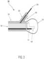
- FIG. 3is a schematic illustration of a tip of a catheter characterized by a sheath channel that contains at least a portion of an endoscopic tool, according to some embodiments of the present invention
- FIG. 4is a schematic illustration of an endoscopic insertion tube, characterized by an adjustable chamber designed to be filled with a wave conductive medium, according to some embodiments of the present invention.
- FIG. 5is a flowchart illustrating a method for imaging a targeted anatomic site by directing an imager within a body lumen, according to some embodiments of the present invention.
- the present inventionin some embodiments thereof, relates to medical devices and, more particularly, but not exclusively, to catheters, endoscopes, endoscopic tools, and intrabody probes.
- Some embodiments of the present inventionrelate to a medical sonography procedure in which an endoscope is used for conveying an ultrasound transducer via a body lumen toward a targeted anatomic site.
- An aspect of some embodiments of the present inventionrelates to a device for intrabody guiding, optionally disposable, that includes a catheter with a shape adjustable chamber, referred to herein as an adjustable chamber, that is placed at the distal end thereof and covers at least a distal end of an imager, such as an ultrasound catheter.
- a catheter with a shape adjustable chamberreferred to herein as an adjustable chamber
- the adjustable chamberis designed to be filled with a wave conductive medium, such as an ultrasound conductive medium, that increases wave conductivity in the space between the ultrasound imager and a body tissue in proximity to a targeted anatomic site.
- the fillingoptionally adjusts the volume and/or the shape of the adjustable chamber to size and/or shape of a body lumen in proximity of a targeted anatomic site. This adjustment is optionally used to establish a contact with the inner walls of the body lumen and/or expand the lumen's diameter. In such a manner, the wave conductivity in the space between the imager and the inner walls increases and the targeted anatomic site may be imaged without the need to fill the whole body lumen with the wave conductive mediums.
- the filling of the adjustable chambermay be performed before, during, and/or after the insertion of the catheter into the body lumen.
- the ultrasound catheterdoes not come in contact with the human body is an advantage as it may be not have to be cleaned or reprocessed between uses on different patients.
- FIG. 1is a schematic illustration of a tip of a device 100 with a catheter 102 , a sheath 115 , an adjustable chamber 104 that covers a portion of an ultrasound catheter 106 , according to some embodiments of the present invention.
- a catheteris an endoscopic tube, a bronchoscope, an endoscope, and/or any other device that is designed to introduce an endoscopic tool in a human body and/or being introduced in a human body.
- the catheter 102is optionally circular and hollow and covers at least a distal end of the ultrasound catheter 106 .
- the catheter 102allows an ultrasonic imager 108 , such as an ultrasonic imaging scanner, to pass therethrough.
- the ultrasonic imaging scanner 108comprises one or more ultrasound transducers 108 , such as one or more linear arrays, phased arrays and/or transesophageal phased arrays and/or any other ultrasound generators, transmitters and/or sensors.
- the one or more ultrasound transducersare referred to herein as an ultrasound transducer.
- adjustable chamber 104wraps the imager 108 , which optionally partially or fully extends beyond a distal extremity of catheter 102 .
- adjustable chamber 104is made of an elastic material, such as a thermoplastic elastomer, for example polyurethane.
- the adjustable chamber 104is filled with a wave conductive medium, such as an ultrasound conductive medium.
- the wave conductive mediummay be, for example, water, saline solution, colloid, gel, or any combination thereof.
- the filling and/or the material of the adjustable chamber 104may be performed and/or selected according to the impedance of the contacted tissue.
- the wave conductive mediumis delivered to the adjustable chamber 104 by a conduit.
- the conduitmay be a designated conduit, such as a feeder and a channel, as shown at 110 , for delivering the wave conductive medium from one end of the device 100 to the other and vice versa.
- the conduitis the gap between the ultrasound catheter 106 and the catheter 102 .
- the conduitis detachable.
- the conduit 110is secured to an outer surface of the catheter 102 , for example, by attachments that do not substantially affect the passage of the conductive fluid.
- the amount of the wave conductive medium that is delivered to and/or from the adjustable chamber 104adjusts the volume of the adjustable chamber 104 .
- the wave conductive mediumstretches the adjustable chamber 104 and allows it to establish physical contact with the inner walls of body lumens that have different perimeters and/or shapes. In such a manner, a physical contact with an area in the proximity of the targeted anatomical site may be established.
- the adjustable chamber 104is an inflatable assembly having inflated and deflated configurations.
- the adjustable chamber 104is optionally designed to establish physical contact with the inner walls of body lumens.
- the diameter of the adjustable chamber 104may be between 2 mm and 50 mm.
- the diameter of the adjustable chamber 104is smaller than the diameter of a working channel of an endoscope so as to allow the passage thereof therethrough.
- the adjustable chamber 104when the adjustable chamber 104 is in a deflated state it does not apply pressure on the inner walls of the body lumens.
- the inflatable adjustable chamber 104may be used to increase ultrasound wave conductivity without moving ultrasound catheter 106 .
- adjustable chamber 104may be filled by directing ultrasound conductive medium into adjustable chamber 104 to increase the contact between the outer surface of adjustable chamber 104 and the targeted anatomic site.
- the inflating and deflating of the adjustable chamber 104may allow maintaining uniform wave conductivity regardless of the diameter of the body lumens.
- the volume of the adjustable chambermay be adjusted to fit the perimeter of the body lumen in the proximity of the targeted anatomical site and assures physical contact that increases the quality of the image that is produced from the ultrasound transmissions of the ultrasound transducer 108 .
- device 100may establish a physical contact with walls of lumens that have variable and/or non-uniform perimeter.
- the device 100comprises a mechanism for extracting gas, such as air, from the adjustable chamber 104 and/or the conduits that are used for delivering the ultrasound conductive medium thereto and therefrom.
- gassuch as air
- the mechanism of the described below pistonis used for pumping gas from the adjustable chamber 104 when the ultrasound catheter cover is vertical and the distal end of the adjustable chamber 104 is positioned to face the ground. Then, the piston may be used for delivering the conductive fluid without or substantially without air, as described above.
- the mechanismincludes a piston, such as the piston that is described below.
- the pistonis connected to a separate conduit that is positioned in the channels that are used for filling the adjustable chamber 104 .
- the pistonis used for venting out the gas when the ultrasound catheter cover is vertical and the distal end of the adjustable chamber 104 faces the top, for example while injecting the conductive fluid.
- the separate conduitis connected to a valve that is controlled according to the orientation of the device 100 . It should be noted that such a conduit may or may not be connected to the piston and/or to any other pump as long as the conduit and fluid injection and deflation system are resistant to gas influx.
- the adjustable chamber 104 and the walls of the catheter 102are made of a material with a different elasticity coefficient.
- the filling of the catheter 102 with ultrasound conductive mediumstretches the catheter 102 to a much lesser degree than the walls of the adjustable chamber 104 , optionally in a manner that allows forward and back movement within the catheter 102 .
- Such a movementmay be taken into account when analyzing the signals of the ultrasonic imager 108 .
- the catheter 102 and the adjustable chamber 104are made from a material having a similar elasticity coefficient and the catheter 102 has walls that are thicker than the walls of the adjustable chamber 104 , for example, as shown at 114 and 116 .
- an ultrasound conductive medium delivered via the catheter 102inflates adjustable chamber 104 without, or substantially without, changing the perimeter of the catheter 102 .
- device 100allows the extending of the volume of adjustable chamber 104 while the volume of catheter 102 does not change substantially and therefore does not apply pressure on the walls of the intrabody lumen through which it has been introduced.
- the material of catheter 102 and the material of adjustable chamber 104have a different elasticity coefficient. In this manner, the introduction of conductive medium expands the adjustable chamber 104 without substantially expanding the perimeter of the catheter 102 .
- catheter 102is made of polyurethane and/or polyvinyl chloride (PVC).
- catheter 102may be formed of a relatively rigid, optionally relatively thin, material, such as glycol-modified polyethylene terephthalate (PETG) and/or acrylic.
- inner diameter 112 of catheter 102measures about 3 millimeters, and is larger than the diameter of ultrasound catheter 106 , which optionally measures 1 mm to 2 mm.
- catheter 102is made of an elastic material, such as a thermoplastic elastomer, for example polyurethane or C-FlexTM thermoplastic elastomer.
- the thickness 114 of the walls of the catheter 102is between 0.05 and 1.0 millimeters. It should be noted that the dimensions of inner diameter 112 and wall thickness 114 are merely exemplary.
- the adjustable chamber 104is an integral part of the catheter 102 and is an extension thereof.
- the adjustable chamber 104is detachable from the catheter 102 .
- the conduit 110at the proximal extremity is connected to a pressure control device, such as a piston-cylinder device, which is controlled by a user to control the introduction of the ultrasound conductive medium to adjustable chamber 104 .
- a pressure control devicesuch as a piston-cylinder device
- the pistonis controlled by a user through an electronically controlled linear actuator.
- the piston-cylinder deviceis a syringe.
- the syringeincludes a barrel characterized by screw threads, which allows a user to rotate the barrel in and out of the syringe's cylinder, with a high degree of precision.
- the conduit 110is connected to a variable pressure regulator for controlling the inflation and deflation of adjustable chamber 104 .
- the variable pressure regulatormay be of a common type where there is a spring loaded diaphragm, in which a pressure exerted by the spring on the diaphragm dictates a pressure of the ultrasound conductive medium flowing through conduit 110 .
- Variable pressure regulators of this typeare manufactured, for example, by Watts Regulator Company, and Fairchild Industrial Products Company.
- FIG. 2is a schematic illustration of a device 200 for simultaneously introducing optical and ultrasound imagers, according to some embodiments of the present invention.
- the device 200is characterized by a catheter 102 , an adjustable chamber 104 and a tool deflector 206 , and traversed by an endoscopic tool 204 .
- device 200may be comprised of an endoscope protective sheath 223 having a channel 224 with a window 222 at its distal end.
- device 200may be used for introducing an optic imager, such as an optic fiber 221 .
- the window 222is made of a clear rigid material, such as glass, Plexiglas, and/or polyester, for allowing the optic imager to capture video images.
- the video imageris used for guiding the device 200 toward a targeted anatomic site.
- the device 200has an aperture 202 that allows the passage of the endoscopic tool 204 toward an anatomical site.
- device 200further includes tool deflector 206 , for changing the orientation of the endoscopic tool 204 .
- the tool deflector 206is an electromechanical deflector, a cam type deflector, and/or an inflatable deflector, for example as described in U.S. Patent Application 61/129,344 filed in Jun. 19, 2008, which is incorporated herein by reference.
- the tool deflector 206is mounted on the outer surface of the intrabody guiding tube of the catheter 102 , as pictured.
- tool deflector 206may provide the endoscopic tool 204 an additional degree of freedom that decreases the dependency of the endoscopic tool 204 on the movement of ultrasound catheter 106 .
- the tool deflector 206allows a change in the orientation of the endoscopic tool 204 , independent of the movement of the intrabody guide tube of the catheter 102 and ultrasound catheter 106 .
- the tool deflector 206may divert the endoscopic tool 204 toward the targeted anatomic site without changing the orientation of the intrabody guide tube of the catheter 102 and the ultrasound catheter 106 , for example, if ultrasound catheter 106 is placed closely enough to a targeted anatomic site that is to be treated and/or probed by the endoscopic tool 204 .
- the catheter 102covers at least a distal end of the ultrasound catheter 106 , and provides tool deflector 206 , to control an orientation of endoscopic tool 204 .
- a real time image that is provided by ultrasound transducer 108is optionally analyzed by an image processor in order to determine the orientation of the endoscopic tool 204 .
- a processing unitis used for creating a graphic overlay representing a future trajectory of endoscopic tool 204 . The graphic overlay is superimposed on the image, and helps a user to guide the endoscopic tool 204 toward the targeted anatomic site that is imaged by the ultrasound transducer 108 .
- FIG. 3is a schematic illustration of a device 300 that has a sheath channel that covers at least a portion of an endoscopic tool 204 , according to some embodiments of the present invention.
- device 300includes a working channel 302 , which covers at least a portion of an endoscopic tool 204 , and also serves to guide it.
- the sheath channel 302comprises an aperture and/or a nozzle at the tip of the working channel 302 for allowing a distal tip of endoscopic tool 204 to directly contact the walls of a body lumen.
- working channel 302terminates prior to the adjustable chamber 104 .
- sheath channel 302assures that the endoscopic tool 204 does not puncture the adjustable chamber 104 .
- the working channel 302is an integral part of the catheter 102 .
- FIG. 4is a schematic illustration of a device 400 with an integrated channel 410 for conducting a deflectable endoscopic tool 412 , according to some embodiments of the present invention.
- the device 400includes the channel 402 for allowing an ultrasonic imaging scanner 406 to pass therethrough and an adjustable chamber 408 that covers the distal opening thereof and functions similarly to the described above.
- the adjustable chamber 408is optionally attached by a rubber-band or a metal band to end of the device 400 .
- the device 400further includes a second channel 410 for housing an endoscopic tool 412 .
- the second channel 410has a tool deflector 414 that is placed at a distal end thereof and allows changing the orientation of endoscopic tool 412 .
- the tool deflector 414may be placed inside the second channel 410 , outside second channel 410 , or both inside and outside second channel 410 .
- the tool deflector 414is one of the tool deflectors described above.
- ultrasound conductive mediumis conducted toward and/or from the adjustable chamber 408 , via a channel 402 , similarly to the described above.
- device 400includes an ultrasound conductive medium channel 416 , for conducting the ultrasound conductive medium toward and/or from adjustable chamber 408 .
- ultrasound conductive mediumis directed into and out of adjustable chamber 408 , using units, such as a piston-cylinder device, described above.
- adjustable chamber 408is optionally a disposable adjustable chamber that covers the ultrasonic imaging scanner 406 .
- the ultrasonic imaging scanner 406is not contaminated during the endoscopy procedure and therefore the need to sterilize and/or decontaminate it is reduced and/or eliminated.
- the endoscope to which device 400 is used in conjunction withis a bronchoscope that is used for reaching remote areas within the airways and probing and/or treating the above areas.
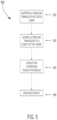
- FIG. 5is a flowchart illustrating a method 500 for imaging a targeted anatomic site within a body lumen, according to some embodiments of the present invention.
- an endoscopeis used for conveying an ultrasound transducer in an adjustable chamber via a body lumen toward a targeted anatomic site, as described above.
- the deviceis one of the devices that are depicted in FIGS. 1 and 4 .
- the ultrasound transduceris guided by a user toward a desired targeted anatomic site, for example, by manipulations of the endoscope in a body lumen.
- an ultrasound conductive mediumis introduced into or aspirated from the adjustable chamber, for example as shown at numeral 104 of FIGS. 1 , 2 , and 3 , or numeral 408 of FIG. 4 .
- the ultrasound conductive mediumextends the adjustable chamber so as to increase the wave conductivity in the space between the imager and the inner wall of a lumen, optionally as further described above.
- the wave conductivityallows the ultrasound transducer to image the targeted anatomic site.
- the adjustable chambermay be deflated and/or inflated to refine the ultrasonic imaging of the targeted anatomic site.
- compositions, method or structuremay include additional ingredients, steps and/or parts, but only if the additional ingredients, steps and/or parts do not materially alter the basic and novel characteristics of the claimed composition, method or structure.
- a compoundor “at least one compound” may include a plurality of compounds, including mixtures thereof.
- range formatis merely for convenience and brevity and should not be construed as an inflexible limitation on the scope of the invention. Accordingly, the description of a range should be considered to have specifically disclosed all the possible subranges as well as individual numerical values within that range. For example, description of a range such as from 1 to 6 should be considered to have specifically disclosed subranges such as from 1 to 3, from 1 to 4, from 1 to 5, from 2 to 4, from 2 to 6, from 3 to 6 etc., as well as individual numbers within that range, for example, 1, 2, 3, 4, 5, and 6. This applies regardless of the breadth of the range.
- a numerical rangeis indicated herein, it is meant to include any cited numeral (fractional or integral) within the indicated range.
- the phrases “ranging/ranges between” a first indicate number and a second indicate number and “ranging/ranges from” a first indicate number “to” a second indicate numberare used herein interchangeably and are meant to include the first and second indicated numbers and all the fractional and integral numerals therebetween.
Landscapes
- Life Sciences & Earth Sciences (AREA)
- Health & Medical Sciences (AREA)
- Biomedical Technology (AREA)
- Biophysics (AREA)
- Nuclear Medicine, Radiotherapy & Molecular Imaging (AREA)
- Pathology (AREA)
- Radiology & Medical Imaging (AREA)
- Engineering & Computer Science (AREA)
- Physics & Mathematics (AREA)
- Heart & Thoracic Surgery (AREA)
- Medical Informatics (AREA)
- Molecular Biology (AREA)
- Surgery (AREA)
- Animal Behavior & Ethology (AREA)
- General Health & Medical Sciences (AREA)
- Public Health (AREA)
- Veterinary Medicine (AREA)
- Ultra Sonic Daignosis Equipment (AREA)
Abstract
Description
Claims (11)
Priority Applications (2)
| Application Number | Priority Date | Filing Date | Title |
|---|---|---|---|
| US15/818,026US11583245B2 (en) | 2008-06-19 | 2017-11-20 | Method and system for intrabody imaging |
| US18/068,281US20230117416A1 (en) | 2009-06-18 | 2022-12-19 | Method and system for intrabody imaging |
Applications Claiming Priority (4)
| Application Number | Priority Date | Filing Date | Title |
|---|---|---|---|
| US12934408P | 2008-06-19 | 2008-06-19 | |
| US12/486,795US20090318797A1 (en) | 2008-06-19 | 2009-06-18 | System and method for deflecting endoscopic tools |
| US13/330,950US9820719B2 (en) | 2008-06-19 | 2011-12-20 | Method and system for intrabody imaging |
| US15/818,026US11583245B2 (en) | 2008-06-19 | 2017-11-20 | Method and system for intrabody imaging |
Related Parent Applications (1)
| Application Number | Title | Priority Date | Filing Date |
|---|---|---|---|
| US13/330,950ContinuationUS9820719B2 (en) | 2008-06-19 | 2011-12-20 | Method and system for intrabody imaging |
Related Child Applications (1)
| Application Number | Title | Priority Date | Filing Date |
|---|---|---|---|
| US18/068,281DivisionUS20230117416A1 (en) | 2009-06-18 | 2022-12-19 | Method and system for intrabody imaging |
Publications (2)
| Publication Number | Publication Date |
|---|---|
| US20180070918A1 US20180070918A1 (en) | 2018-03-15 |
| US11583245B2true US11583245B2 (en) | 2023-02-21 |
Family
ID=45925679
Family Applications (2)
| Application Number | Title | Priority Date | Filing Date |
|---|---|---|---|
| US13/330,950Active2029-11-15US9820719B2 (en) | 2008-06-19 | 2011-12-20 | Method and system for intrabody imaging |
| US15/818,026Active2032-01-24US11583245B2 (en) | 2008-06-19 | 2017-11-20 | Method and system for intrabody imaging |
Family Applications Before (1)
| Application Number | Title | Priority Date | Filing Date |
|---|---|---|---|
| US13/330,950Active2029-11-15US9820719B2 (en) | 2008-06-19 | 2011-12-20 | Method and system for intrabody imaging |
Country Status (1)
| Country | Link |
|---|---|
| US (2) | US9820719B2 (en) |
Cited By (3)
| Publication number | Priority date | Publication date | Assignee | Title |
|---|---|---|---|---|
| US20240081780A1 (en)* | 2022-09-13 | 2024-03-14 | Fujifilm Healthcare Corporation | Ultrasonic diagnostic apparatus |
| US12064084B2 (en)* | 2020-09-08 | 2024-08-20 | Fujifilm Corporation | Ultrasound endoscope |
| US12295787B2 (en)* | 2014-03-31 | 2025-05-13 | Fujifilm Corporation | Ultrasonic endoscope |
Families Citing this family (13)
| Publication number | Priority date | Publication date | Assignee | Title |
|---|---|---|---|---|
| US10244928B2 (en) | 2007-09-05 | 2019-04-02 | Cogentix Medical, Inc. | Compact endoscope tip and method for constructing same |
| US9820719B2 (en) | 2008-06-19 | 2017-11-21 | Cogentix Medical, Inc. | Method and system for intrabody imaging |
| US20090318797A1 (en)* | 2008-06-19 | 2009-12-24 | Vision-Sciences Inc. | System and method for deflecting endoscopic tools |
| US10307135B2 (en)* | 2013-11-20 | 2019-06-04 | Advanced Access Solutions, Inc. | Intravascular ultrasound needle guide |
| US9694163B2 (en) | 2013-12-17 | 2017-07-04 | Biovision Technologies, Llc | Surgical device for performing a sphenopalatine ganglion block procedure |
| US10016580B2 (en) | 2013-12-17 | 2018-07-10 | Biovision Technologies, Llc | Methods for treating sinus diseases |
| US9510743B2 (en) | 2013-12-17 | 2016-12-06 | Biovision Technologies, Llc | Stabilized surgical device for performing a sphenopalatine ganglion block procedure |
| US9516995B2 (en) | 2013-12-17 | 2016-12-13 | Biovision Technologies, Llc | Surgical device for performing a sphenopalatine ganglion block procedure |
| US11806126B2 (en)* | 2017-05-10 | 2023-11-07 | Navix International Limited | Property- and position-based catheter probe target identification |
| WO2020005910A1 (en) | 2018-06-28 | 2020-01-02 | Sandler Scientific, Llc | Sino-nasal rinse delivery device with agitation, flow-control and integrated medication management system |
| US20240023929A1 (en)* | 2022-07-20 | 2024-01-25 | SoundCath, Inc. | Ultrasonic catheter |
| AU2023342382A1 (en)* | 2022-09-16 | 2025-03-06 | Cardiosight, Inc. | Surgical access device having onboard balloon visualization module |
| CN116898385A (en)* | 2023-07-04 | 2023-10-20 | 北京大学 | Insertion instrument and endoscope |
Citations (99)
| Publication number | Priority date | Publication date | Assignee | Title |
|---|---|---|---|---|
| US4040413A (en) | 1974-07-18 | 1977-08-09 | Fuji Photo Optical Co. Ltd. | Endoscope |
| US4364629A (en) | 1979-05-16 | 1982-12-21 | Carl Zeiss-Stiftung | Operation microscope having a small working distance |
| US4406656A (en) | 1981-06-01 | 1983-09-27 | Brack Gillium Hattler | Venous catheter having collapsible multi-lumens |
| US4433692A (en)* | 1981-05-20 | 1984-02-28 | Olympus Optical Co., Ltd. | Ultrasonic diagnosis device |
| US4545367A (en)* | 1982-07-16 | 1985-10-08 | Cordis Corporation | Detachable balloon catheter and method of use |
| US4622954A (en) | 1984-05-15 | 1986-11-18 | Fuji Photo Optical Co., Ltd. | Endoscope having a plate-like image sensor for forming images |
| US4646722A (en) | 1984-12-10 | 1987-03-03 | Opielab, Inc. | Protective endoscope sheath and method of installing same |
| US4676228A (en) | 1985-10-25 | 1987-06-30 | Krasner Jerome L | Medical apparatus having inflatable cuffs and a middle expandable section |
| US4773396A (en) | 1986-08-11 | 1988-09-27 | Olympus Optical Co., Ltd. | Endoscope |
| US4830460A (en) | 1987-05-19 | 1989-05-16 | Advanced Interventional Systems, Inc. | Guidance system and method for delivery system for high-energy pulsed ultraviolet laser light |
| US4841952A (en) | 1986-11-06 | 1989-06-27 | Olympus Optical Co., Ltd. | Endoscope with an optical system |
| US4856495A (en) | 1986-09-25 | 1989-08-15 | Olympus Optical Co., Ltd. | Endoscope apparatus |
| US4881810A (en) | 1986-11-10 | 1989-11-21 | Olympus Optical Co., Ltd. | Endoscope with a removable cover member |
| US5025778A (en) | 1990-03-26 | 1991-06-25 | Opielab, Inc. | Endoscope with potential channels and method of using the same |
| US5051824A (en) | 1989-10-30 | 1991-09-24 | Olympus Optical Co., Ltd. | Electronic scope having detachable frame to which solid state imaging device is fastened |
| US5083549A (en) | 1989-02-06 | 1992-01-28 | Candela Laser Corporation | Endoscope with tapered shaft |
| US5166787A (en) | 1989-06-28 | 1992-11-24 | Karl Storz Gmbh & Co. | Endoscope having provision for repositioning a video sensor to a location which does not provide the same cross-sectionally viewed relationship with the distal end |
| US5167220A (en) | 1990-08-09 | 1992-12-01 | Brown Cathy K | Systems and methods for maintaining a clear visual field during endoscopic procedures |
| US5201908A (en) | 1991-06-10 | 1993-04-13 | Endomedical Technologies, Inc. | Sheath for protecting endoscope from contamination |
| US5217001A (en) | 1991-12-09 | 1993-06-08 | Nakao Naomi L | Endoscope sheath and related method |
| US5305736A (en) | 1991-04-26 | 1994-04-26 | Asahi Kogaku Kogyo Kabushiki Kaisha | Distal end part of endoscope |
| US5373845A (en)* | 1992-05-22 | 1994-12-20 | Echo Cath, Ltd. | Apparatus and method for forward looking volume imaging |
| US5377688A (en) | 1993-04-16 | 1995-01-03 | The Trustees Of Columbia University In The City Of New York | Apparatus and method to objectively measure sensory discrimination thresholds in the upper aero digestive tract |
| US5379756A (en) | 1992-09-11 | 1995-01-10 | Welch Allyn, Inc. | Replaceable lens assembly for video laparoscope |
| WO1995018562A1 (en) | 1994-01-05 | 1995-07-13 | Endomedical Technologies Inc. | Collapsible access channel system |
| US5460168A (en) | 1992-12-25 | 1995-10-24 | Olympus Optical Co., Ltd. | Endoscope cover assembly and cover-system endoscope |
| US5483951A (en) | 1994-02-25 | 1996-01-16 | Vision-Sciences, Inc. | Working channels for a disposable sheath for an endoscope |
| US5489256A (en) | 1992-09-01 | 1996-02-06 | Adair; Edwin L. | Sterilizable endoscope with separable disposable tube assembly |
| US5547457A (en) | 1993-01-22 | 1996-08-20 | Olympus Optical Co., Ltd. | Objective optical system for endoscopes |
| US5588432A (en) | 1988-03-21 | 1996-12-31 | Boston Scientific Corporation | Catheters for imaging, sensing electrical potentials, and ablating tissue |
| US5734418A (en) | 1996-07-17 | 1998-03-31 | Welch Allyn, Inc. | Endoscope with tab imager package |
| US5749889A (en) | 1996-02-13 | 1998-05-12 | Imagyn Medical, Inc. | Method and apparatus for performing biopsy |
| US5810776A (en) | 1996-02-13 | 1998-09-22 | Imagyn Medical, Inc. | Method and apparatus for performing laparoscopy |
| US5823940A (en) | 1993-08-18 | 1998-10-20 | Vista Medical Technologies, Inc. | Optical surgical device for examining genitourinary tissue |
| US5842973A (en) | 1994-05-17 | 1998-12-01 | Bullard; James Roger | Nasal intubation apparatus |
| US5871440A (en) | 1995-12-15 | 1999-02-16 | Olympus Optical Co., Ltd. | Endoscope |
| US5898185A (en) | 1997-01-24 | 1999-04-27 | International Business Machines Corporation | Hybrid organic-inorganic semiconductor light emitting diodes |
| US5940126A (en) | 1994-10-25 | 1999-08-17 | Kabushiki Kaisha Toshiba | Multiple image video camera apparatus |
| US5961445A (en) | 1995-05-31 | 1999-10-05 | Machida Endoscope Co., Ltd. | Endoscope having replaceable objective unit |
| US5966168A (en) | 1994-11-25 | 1999-10-12 | Olympus Optical Co., Ltd. | Endoscope apparatus |
| GB2336540A (en) | 1998-04-21 | 1999-10-27 | Alan James Purveur | Flexible endoscope cover |
| US6095970A (en) | 1997-02-19 | 2000-08-01 | Asahi Kogaku Kogyo Kabushiki Kaisha | Endoscope |
| US6146326A (en) | 1996-01-31 | 2000-11-14 | Pollack; Michael J. | Endoscope |
| WO2000071016A1 (en) | 1999-05-26 | 2000-11-30 | Scimed Life Systems, Inc. | A suction device for an endoscope |
| US6174280B1 (en) | 1998-11-19 | 2001-01-16 | Vision Sciences, Inc. | Sheath for protecting and altering the bending characteristics of a flexible endoscope |
| US20010000040A1 (en) | 1999-03-12 | 2001-03-15 | Ronald Adams | Controllable endoscopic sheath apparatus and related method of use |
| US20010047135A1 (en)* | 1996-07-08 | 2001-11-29 | Daniels Douglas J. | Diagnosing and performing interventional procedures on tissue in vivo |
| US6328691B1 (en) | 1996-07-26 | 2001-12-11 | Karl Storz Gmbh & Co. Kg | Endoscope with at least one glued and additionally welded end window |
| US6358200B1 (en) | 1999-09-01 | 2002-03-19 | Circon Corporation | Continuous flow resectoscope with single tube sheath assembly and rotatable connection |
| US6361491B1 (en) | 1998-12-15 | 2002-03-26 | Olympus Optical Co., Ltd. | Optical adaptor for highy precision endoscope |
| US20020062083A1 (en)* | 2000-11-21 | 2002-05-23 | Asahi Kogaku Kogyo Kabushiki Kaisha | Ultrasonic endoscope |
| US6443968B1 (en) | 1997-10-09 | 2002-09-03 | Ethicon Endo-Surgery, Inc. | Dual cam trigger for a surgical instrument |
| US6461294B1 (en) | 2000-10-30 | 2002-10-08 | Vision Sciences, Inc. | Inflatable member for an endoscope sheath |
| US6579301B1 (en) | 2000-11-17 | 2003-06-17 | Syntheon, Llc | Intragastric balloon device adapted to be repeatedly varied in volume without external assistance |
| US20030114878A1 (en)* | 2001-12-14 | 2003-06-19 | The Regents Of The University Of California | Catheter based balloon for therapy modification and positioning of tissue |
| US20030130564A1 (en) | 2002-01-04 | 2003-07-10 | Stephen Martone | Endoscope assemblies having working channels with reduced bending and stretching resistance |
| JP3429536B2 (en) | 1993-09-30 | 2003-07-22 | オリンパス光学工業株式会社 | Endoscope sheath |
| US20030153833A1 (en) | 1997-05-01 | 2003-08-14 | Bennett Frederick J. | Ultrasound catheter with utility lumen |
| US20040019254A1 (en) | 2000-04-03 | 2004-01-29 | Amir Belson | Steerable segmented endoscope and method of insertion |
| US6692431B2 (en) | 2001-09-07 | 2004-02-17 | Smith & Nephew, Inc. | Endoscopic system with a solid-state light source |
| US20040082859A1 (en)* | 2002-07-01 | 2004-04-29 | Alan Schaer | Method and apparatus employing ultrasound energy to treat body sphincters |
| US20040082883A1 (en)* | 2002-10-18 | 2004-04-29 | Fuji Photo Optical Co., Ltd. | Ultrasound endoscope |
| US20040092821A1 (en) | 2000-11-24 | 2004-05-13 | Steffen Hering | Ultrasonic probe with positioning device for examination devices and operation devices |
| US20040143162A1 (en) | 2001-04-27 | 2004-07-22 | Beat Krattiger | Optical instrument, in particular an endoscope, having an interchangeable head |
| US6808520B1 (en) | 1991-12-13 | 2004-10-26 | Endovascular Technologies, Inc. | Dual valve, flexible expandable sheath and method |
| US20040230095A1 (en) | 2003-05-16 | 2004-11-18 | David Stefanchik | Medical apparatus for use with an endoscope |
| US6827710B1 (en) | 1996-11-26 | 2004-12-07 | Edwards Lifesciences Corporation | Multiple lumen access device |
| WO2005016181A2 (en) | 2003-08-04 | 2005-02-24 | Vision-Sciences, Inc. | Sheath with channel for endoscope |
| US20050049455A1 (en) | 2000-04-17 | 2005-03-03 | Olympus Corporation | Endoscope and endoscope system thereof |
| US20050131278A1 (en)* | 2003-12-16 | 2005-06-16 | Olympus Winter & Ibe Gmbh | Endoscope |
| US20050182299A1 (en) | 2002-10-18 | 2005-08-18 | D'amelio Frank | Removable optical assembly for a medical instrument |
| US20050261586A1 (en) | 2004-05-18 | 2005-11-24 | Makin Inder R S | Medical system having an ultrasound source and an acoustic coupling medium |
| US20050277808A1 (en) | 2004-05-14 | 2005-12-15 | Elazar Sonnenschein | Methods and devices related to camera connectors |
| US20060020171A1 (en) | 2002-10-21 | 2006-01-26 | Gilreath Mark G | Intubation and imaging device and system |
| US7044135B2 (en) | 1997-05-09 | 2006-05-16 | The Regents Of The University Of California | Device and method for forming a circumferential conduction block in a pulmonary vein |
| US20060149127A1 (en) | 2004-12-30 | 2006-07-06 | Seddiqui Fred R | Disposable multi-lumen catheter with reusable stylet |
| US20070038089A1 (en)* | 2005-06-29 | 2007-02-15 | Olympus Medical Systems Corp. | Transurethral diagnostic method and treatment method using ultrasonic endoscope |
| US20070203396A1 (en)* | 2006-02-28 | 2007-08-30 | Mccutcheon John G | Endoscopic Tool |
| WO2007103355A1 (en) | 2006-03-03 | 2007-09-13 | Wilson-Cook Medical, Inc. | Endoscopic elevator apparatus |
| WO2007103296A2 (en) | 2006-03-03 | 2007-09-13 | Wilson-Cook Medical, Inc. | Endoscopic apparatus having an improved catheter |
| US20070249940A1 (en)* | 2006-03-22 | 2007-10-25 | Fujinon Corporation | Ultrasonic endoscope |
| US20070265494A1 (en) | 2006-05-10 | 2007-11-15 | Boston Scientific Scimed Inc. | Flexible and retractable endoscope elevator |
| US20070293719A1 (en) | 2006-06-20 | 2007-12-20 | Boston Scientific Scimed, Inc. | Medical device for use in endoscopic procedure |
| US20080004528A1 (en)* | 2006-01-25 | 2008-01-03 | Fitzsimons Thomas P | Ultrasound medical system and methods |
| US7410462B2 (en) | 2004-12-13 | 2008-08-12 | Gyrus Acmi, Inc. | Hermetic endoscope assemblage |
| EP2011431A1 (en) | 2006-04-21 | 2009-01-07 | Olympus Medical Systems Corp. | Endoscope system and lens unit |
| US20090318797A1 (en) | 2008-06-19 | 2009-12-24 | Vision-Sciences Inc. | System and method for deflecting endoscopic tools |
| US7645229B2 (en) | 2003-09-26 | 2010-01-12 | Armstrong David N | Instrument and method for endoscopic visualization and treatment of anorectal fistula |
| US20100042112A1 (en) | 2008-08-14 | 2010-02-18 | Monteris Medical, Inc. | Stereotactic drive system |
| US20100125164A1 (en)* | 2008-11-18 | 2010-05-20 | Labombard Denis | Adapter for attaching devices to endoscopes |
| US7753842B2 (en) | 2001-06-28 | 2010-07-13 | Given Imaging Ltd. | In vivo imaging device with a small cross sectional area |
| US20110152618A1 (en) | 2009-12-18 | 2011-06-23 | Cook Medical Technologies Llc | Endoscope cap with ramp |
| US8002699B2 (en) | 2004-02-16 | 2011-08-23 | Karl Storz Gmbh & Co. Kg | Endoscope and method for fixing optical fibers therein |
| US20120089028A1 (en) | 2008-06-19 | 2012-04-12 | Vision - Sciences Inc. | Method and system for intrabody imaging |
| US8435170B2 (en) | 2008-01-11 | 2013-05-07 | Boston Scientific Scimed, Inc. | Positioning system for securing a treatment instrument at the end of a medical device |
| US8692874B2 (en) | 2007-04-17 | 2014-04-08 | Gyrus Acmi, Inc. | Imaging systems and methods, particularly for use with medical instrument used in open surgery |
| US20140364691A1 (en) | 2013-03-28 | 2014-12-11 | Endochoice, Inc. | Circuit Board Assembly of A Multiple Viewing Elements Endoscope |
| US20150031947A1 (en) | 2013-03-08 | 2015-01-29 | Olympus Medical Systems Corp. | Endoscope |
| US10244928B2 (en) | 2007-09-05 | 2019-04-02 | Cogentix Medical, Inc. | Compact endoscope tip and method for constructing same |
- 2011
- 2011-12-20USUS13/330,950patent/US9820719B2/enactiveActive
- 2017
- 2017-11-20USUS15/818,026patent/US11583245B2/enactiveActive
Patent Citations (113)
| Publication number | Priority date | Publication date | Assignee | Title |
|---|---|---|---|---|
| US4040413A (en) | 1974-07-18 | 1977-08-09 | Fuji Photo Optical Co. Ltd. | Endoscope |
| US4364629A (en) | 1979-05-16 | 1982-12-21 | Carl Zeiss-Stiftung | Operation microscope having a small working distance |
| US4433692A (en)* | 1981-05-20 | 1984-02-28 | Olympus Optical Co., Ltd. | Ultrasonic diagnosis device |
| US4406656A (en) | 1981-06-01 | 1983-09-27 | Brack Gillium Hattler | Venous catheter having collapsible multi-lumens |
| US4545367A (en)* | 1982-07-16 | 1985-10-08 | Cordis Corporation | Detachable balloon catheter and method of use |
| US4622954A (en) | 1984-05-15 | 1986-11-18 | Fuji Photo Optical Co., Ltd. | Endoscope having a plate-like image sensor for forming images |
| US4646722A (en) | 1984-12-10 | 1987-03-03 | Opielab, Inc. | Protective endoscope sheath and method of installing same |
| US4676228A (en) | 1985-10-25 | 1987-06-30 | Krasner Jerome L | Medical apparatus having inflatable cuffs and a middle expandable section |
| US4773396A (en) | 1986-08-11 | 1988-09-27 | Olympus Optical Co., Ltd. | Endoscope |
| US4856495A (en) | 1986-09-25 | 1989-08-15 | Olympus Optical Co., Ltd. | Endoscope apparatus |
| US4841952A (en) | 1986-11-06 | 1989-06-27 | Olympus Optical Co., Ltd. | Endoscope with an optical system |
| US4881810A (en) | 1986-11-10 | 1989-11-21 | Olympus Optical Co., Ltd. | Endoscope with a removable cover member |
| US4830460A (en) | 1987-05-19 | 1989-05-16 | Advanced Interventional Systems, Inc. | Guidance system and method for delivery system for high-energy pulsed ultraviolet laser light |
| US5588432A (en) | 1988-03-21 | 1996-12-31 | Boston Scientific Corporation | Catheters for imaging, sensing electrical potentials, and ablating tissue |
| US5083549A (en) | 1989-02-06 | 1992-01-28 | Candela Laser Corporation | Endoscope with tapered shaft |
| US5166787A (en) | 1989-06-28 | 1992-11-24 | Karl Storz Gmbh & Co. | Endoscope having provision for repositioning a video sensor to a location which does not provide the same cross-sectionally viewed relationship with the distal end |
| US5051824A (en) | 1989-10-30 | 1991-09-24 | Olympus Optical Co., Ltd. | Electronic scope having detachable frame to which solid state imaging device is fastened |
| US5025778A (en) | 1990-03-26 | 1991-06-25 | Opielab, Inc. | Endoscope with potential channels and method of using the same |
| US5167220A (en) | 1990-08-09 | 1992-12-01 | Brown Cathy K | Systems and methods for maintaining a clear visual field during endoscopic procedures |
| US5305736A (en) | 1991-04-26 | 1994-04-26 | Asahi Kogaku Kogyo Kabushiki Kaisha | Distal end part of endoscope |
| US5201908A (en) | 1991-06-10 | 1993-04-13 | Endomedical Technologies, Inc. | Sheath for protecting endoscope from contamination |
| US5503616A (en) | 1991-06-10 | 1996-04-02 | Endomedical Technologies, Inc. | Collapsible access channel system |
| US5217001A (en) | 1991-12-09 | 1993-06-08 | Nakao Naomi L | Endoscope sheath and related method |
| US6808520B1 (en) | 1991-12-13 | 2004-10-26 | Endovascular Technologies, Inc. | Dual valve, flexible expandable sheath and method |
| US5373845A (en)* | 1992-05-22 | 1994-12-20 | Echo Cath, Ltd. | Apparatus and method for forward looking volume imaging |
| US5489256A (en) | 1992-09-01 | 1996-02-06 | Adair; Edwin L. | Sterilizable endoscope with separable disposable tube assembly |
| US5379756A (en) | 1992-09-11 | 1995-01-10 | Welch Allyn, Inc. | Replaceable lens assembly for video laparoscope |
| US5460168A (en) | 1992-12-25 | 1995-10-24 | Olympus Optical Co., Ltd. | Endoscope cover assembly and cover-system endoscope |
| US5547457A (en) | 1993-01-22 | 1996-08-20 | Olympus Optical Co., Ltd. | Objective optical system for endoscopes |
| US5377688A (en) | 1993-04-16 | 1995-01-03 | The Trustees Of Columbia University In The City Of New York | Apparatus and method to objectively measure sensory discrimination thresholds in the upper aero digestive tract |
| US5823940A (en) | 1993-08-18 | 1998-10-20 | Vista Medical Technologies, Inc. | Optical surgical device for examining genitourinary tissue |
| JP3429536B2 (en) | 1993-09-30 | 2003-07-22 | オリンパス光学工業株式会社 | Endoscope sheath |
| WO1995018562A1 (en) | 1994-01-05 | 1995-07-13 | Endomedical Technologies Inc. | Collapsible access channel system |
| US5483951A (en) | 1994-02-25 | 1996-01-16 | Vision-Sciences, Inc. | Working channels for a disposable sheath for an endoscope |
| US5842973A (en) | 1994-05-17 | 1998-12-01 | Bullard; James Roger | Nasal intubation apparatus |
| US5940126A (en) | 1994-10-25 | 1999-08-17 | Kabushiki Kaisha Toshiba | Multiple image video camera apparatus |
| US5989185A (en) | 1994-11-25 | 1999-11-23 | Olympus Optical Co., Ltd. | Endoscope apparatus |
| US5966168A (en) | 1994-11-25 | 1999-10-12 | Olympus Optical Co., Ltd. | Endoscope apparatus |
| US5961445A (en) | 1995-05-31 | 1999-10-05 | Machida Endoscope Co., Ltd. | Endoscope having replaceable objective unit |
| US5871440A (en) | 1995-12-15 | 1999-02-16 | Olympus Optical Co., Ltd. | Endoscope |
| US6146326A (en) | 1996-01-31 | 2000-11-14 | Pollack; Michael J. | Endoscope |
| US5810776A (en) | 1996-02-13 | 1998-09-22 | Imagyn Medical, Inc. | Method and apparatus for performing laparoscopy |
| US5749889A (en) | 1996-02-13 | 1998-05-12 | Imagyn Medical, Inc. | Method and apparatus for performing biopsy |
| US20010047135A1 (en)* | 1996-07-08 | 2001-11-29 | Daniels Douglas J. | Diagnosing and performing interventional procedures on tissue in vivo |
| US5734418A (en) | 1996-07-17 | 1998-03-31 | Welch Allyn, Inc. | Endoscope with tab imager package |
| US6328691B1 (en) | 1996-07-26 | 2001-12-11 | Karl Storz Gmbh & Co. Kg | Endoscope with at least one glued and additionally welded end window |
| US6827710B1 (en) | 1996-11-26 | 2004-12-07 | Edwards Lifesciences Corporation | Multiple lumen access device |
| US5898185A (en) | 1997-01-24 | 1999-04-27 | International Business Machines Corporation | Hybrid organic-inorganic semiconductor light emitting diodes |
| US6095970A (en) | 1997-02-19 | 2000-08-01 | Asahi Kogaku Kogyo Kabushiki Kaisha | Endoscope |
| US20030167023A1 (en) | 1997-05-01 | 2003-09-04 | Frederick J. Bennett | Ultrasound catheter for providing a therapeutic effect to a vessel of a body |
| US20030153833A1 (en) | 1997-05-01 | 2003-08-14 | Bennett Frederick J. | Ultrasound catheter with utility lumen |
| US7044135B2 (en) | 1997-05-09 | 2006-05-16 | The Regents Of The University Of California | Device and method for forming a circumferential conduction block in a pulmonary vein |
| US6443968B1 (en) | 1997-10-09 | 2002-09-03 | Ethicon Endo-Surgery, Inc. | Dual cam trigger for a surgical instrument |
| GB2336540A (en) | 1998-04-21 | 1999-10-27 | Alan James Purveur | Flexible endoscope cover |
| US6174280B1 (en) | 1998-11-19 | 2001-01-16 | Vision Sciences, Inc. | Sheath for protecting and altering the bending characteristics of a flexible endoscope |
| US6361491B1 (en) | 1998-12-15 | 2002-03-26 | Olympus Optical Co., Ltd. | Optical adaptor for highy precision endoscope |
| US6761685B2 (en) | 1999-03-12 | 2004-07-13 | Scimed Life Systems, Inc. | Controllable endoscopic sheath apparatus and related method of use |
| US20060264705A1 (en) | 1999-03-12 | 2006-11-23 | Boston Scientific Scimed, Inc. | Controllable endoscopic sheath apparatus and related method of use |
| US20010000040A1 (en) | 1999-03-12 | 2001-03-15 | Ronald Adams | Controllable endoscopic sheath apparatus and related method of use |
| EP1187549A1 (en) | 1999-05-26 | 2002-03-20 | SciMed Life Systems, Inc. | A suction device for an endoscope |
| WO2000071016A1 (en) | 1999-05-26 | 2000-11-30 | Scimed Life Systems, Inc. | A suction device for an endoscope |
| US6358200B1 (en) | 1999-09-01 | 2002-03-19 | Circon Corporation | Continuous flow resectoscope with single tube sheath assembly and rotatable connection |
| US20040019254A1 (en) | 2000-04-03 | 2004-01-29 | Amir Belson | Steerable segmented endoscope and method of insertion |
| US20050049455A1 (en) | 2000-04-17 | 2005-03-03 | Olympus Corporation | Endoscope and endoscope system thereof |
| US6461294B1 (en) | 2000-10-30 | 2002-10-08 | Vision Sciences, Inc. | Inflatable member for an endoscope sheath |
| US6579301B1 (en) | 2000-11-17 | 2003-06-17 | Syntheon, Llc | Intragastric balloon device adapted to be repeatedly varied in volume without external assistance |
| US20020062083A1 (en)* | 2000-11-21 | 2002-05-23 | Asahi Kogaku Kogyo Kabushiki Kaisha | Ultrasonic endoscope |
| US20040092821A1 (en) | 2000-11-24 | 2004-05-13 | Steffen Hering | Ultrasonic probe with positioning device for examination devices and operation devices |
| US20040143162A1 (en) | 2001-04-27 | 2004-07-22 | Beat Krattiger | Optical instrument, in particular an endoscope, having an interchangeable head |
| US7435218B2 (en) | 2001-04-27 | 2008-10-14 | Storz Endoskop Gmbh | Optical instrument, in particular an endoscope, having an interchangeable head |
| US7753842B2 (en) | 2001-06-28 | 2010-07-13 | Given Imaging Ltd. | In vivo imaging device with a small cross sectional area |
| US6692431B2 (en) | 2001-09-07 | 2004-02-17 | Smith & Nephew, Inc. | Endoscopic system with a solid-state light source |
| US20030114878A1 (en)* | 2001-12-14 | 2003-06-19 | The Regents Of The University Of California | Catheter based balloon for therapy modification and positioning of tissue |
| US6740030B2 (en) | 2002-01-04 | 2004-05-25 | Vision Sciences, Inc. | Endoscope assemblies having working channels with reduced bending and stretching resistance |
| US20030130564A1 (en) | 2002-01-04 | 2003-07-10 | Stephen Martone | Endoscope assemblies having working channels with reduced bending and stretching resistance |
| US20040082859A1 (en)* | 2002-07-01 | 2004-04-29 | Alan Schaer | Method and apparatus employing ultrasound energy to treat body sphincters |
| US20050182299A1 (en) | 2002-10-18 | 2005-08-18 | D'amelio Frank | Removable optical assembly for a medical instrument |
| US20040082883A1 (en)* | 2002-10-18 | 2004-04-29 | Fuji Photo Optical Co., Ltd. | Ultrasound endoscope |
| US7878972B2 (en) | 2002-10-18 | 2011-02-01 | Gyrus Acmi, Inc. | Removable optical assembly for a medical instrument |
| US20060020171A1 (en) | 2002-10-21 | 2006-01-26 | Gilreath Mark G | Intubation and imaging device and system |
| US20040230096A1 (en) | 2003-05-16 | 2004-11-18 | David Stefanchik | Method of guiding medical devices |
| US20040230095A1 (en) | 2003-05-16 | 2004-11-18 | David Stefanchik | Medical apparatus for use with an endoscope |
| WO2005016181A2 (en) | 2003-08-04 | 2005-02-24 | Vision-Sciences, Inc. | Sheath with channel for endoscope |
| US7645229B2 (en) | 2003-09-26 | 2010-01-12 | Armstrong David N | Instrument and method for endoscopic visualization and treatment of anorectal fistula |
| US20050131278A1 (en)* | 2003-12-16 | 2005-06-16 | Olympus Winter & Ibe Gmbh | Endoscope |
| US8002699B2 (en) | 2004-02-16 | 2011-08-23 | Karl Storz Gmbh & Co. Kg | Endoscope and method for fixing optical fibers therein |
| US20050277808A1 (en) | 2004-05-14 | 2005-12-15 | Elazar Sonnenschein | Methods and devices related to camera connectors |
| US7883468B2 (en) | 2004-05-18 | 2011-02-08 | Ethicon Endo-Surgery, Inc. | Medical system having an ultrasound source and an acoustic coupling medium |
| US20050261586A1 (en) | 2004-05-18 | 2005-11-24 | Makin Inder R S | Medical system having an ultrasound source and an acoustic coupling medium |
| US8568300B2 (en) | 2004-12-13 | 2013-10-29 | Gyrus Acmi, Inc. | Hermetic endoscope assemblage |
| US7410462B2 (en) | 2004-12-13 | 2008-08-12 | Gyrus Acmi, Inc. | Hermetic endoscope assemblage |
| US20060149127A1 (en) | 2004-12-30 | 2006-07-06 | Seddiqui Fred R | Disposable multi-lumen catheter with reusable stylet |
| US20070038089A1 (en)* | 2005-06-29 | 2007-02-15 | Olympus Medical Systems Corp. | Transurethral diagnostic method and treatment method using ultrasonic endoscope |
| US20080004528A1 (en)* | 2006-01-25 | 2008-01-03 | Fitzsimons Thomas P | Ultrasound medical system and methods |
| US20070203396A1 (en)* | 2006-02-28 | 2007-08-30 | Mccutcheon John G | Endoscopic Tool |
| WO2007103296A2 (en) | 2006-03-03 | 2007-09-13 | Wilson-Cook Medical, Inc. | Endoscopic apparatus having an improved catheter |
| WO2007103355A1 (en) | 2006-03-03 | 2007-09-13 | Wilson-Cook Medical, Inc. | Endoscopic elevator apparatus |
| US20070249940A1 (en)* | 2006-03-22 | 2007-10-25 | Fujinon Corporation | Ultrasonic endoscope |
| EP2011431A1 (en) | 2006-04-21 | 2009-01-07 | Olympus Medical Systems Corp. | Endoscope system and lens unit |
| US20070265494A1 (en) | 2006-05-10 | 2007-11-15 | Boston Scientific Scimed Inc. | Flexible and retractable endoscope elevator |
| US20070293719A1 (en) | 2006-06-20 | 2007-12-20 | Boston Scientific Scimed, Inc. | Medical device for use in endoscopic procedure |
| US8692874B2 (en) | 2007-04-17 | 2014-04-08 | Gyrus Acmi, Inc. | Imaging systems and methods, particularly for use with medical instrument used in open surgery |
| US20190208999A1 (en) | 2007-09-05 | 2019-07-11 | Cogentix Medical, Inc. | Compact endoscope tip and method for constructing same |
| US10244928B2 (en) | 2007-09-05 | 2019-04-02 | Cogentix Medical, Inc. | Compact endoscope tip and method for constructing same |
| US8435170B2 (en) | 2008-01-11 | 2013-05-07 | Boston Scientific Scimed, Inc. | Positioning system for securing a treatment instrument at the end of a medical device |
| US20090318797A1 (en) | 2008-06-19 | 2009-12-24 | Vision-Sciences Inc. | System and method for deflecting endoscopic tools |
| US20120089028A1 (en) | 2008-06-19 | 2012-04-12 | Vision - Sciences Inc. | Method and system for intrabody imaging |
| US9820719B2 (en) | 2008-06-19 | 2017-11-21 | Cogentix Medical, Inc. | Method and system for intrabody imaging |
| US20100042112A1 (en) | 2008-08-14 | 2010-02-18 | Monteris Medical, Inc. | Stereotactic drive system |
| US20100125164A1 (en)* | 2008-11-18 | 2010-05-20 | Labombard Denis | Adapter for attaching devices to endoscopes |
| US20110152618A1 (en) | 2009-12-18 | 2011-06-23 | Cook Medical Technologies Llc | Endoscope cap with ramp |
| US20150031947A1 (en) | 2013-03-08 | 2015-01-29 | Olympus Medical Systems Corp. | Endoscope |
| US20140364691A1 (en) | 2013-03-28 | 2014-12-11 | Endochoice, Inc. | Circuit Board Assembly of A Multiple Viewing Elements Endoscope |
Non-Patent Citations (12)
| Title |
|---|
| Communication dated Aug. 6, 2014 in connection with European Patent Application No. 08163701.9, 4 pages. |
| Communication dated Feb. 21, 2011 in connection with European Patent Application No. 04780129.5, 9 pages. |
| Communication dated Jul. 19, 2011 in connection with European Patent Application No. 04780129.5, 7 pages. |
| Communication dated Jun. 5, 2012 in connection with European Patent Application No. 08163701.9, 4 pages. |
| Communication dated Sep. 25, 2009 in connection with European Patent Application No. 08163701.9, 4 pages. |
| Extended European Search Report dated Mar. 27, 2015 in connection with European Patent Application No. 14198653.9, 8 pages. |
| International Preliminary Report on Patentability dated Feb. 15, 2006 in connection with PCT/US2004/025238, 14 pages. |
| International Search Report and Written Opinion dated Feb. 14, 2005 in connection with International Patent Application No. PCT/US2004/025238, 7 pages. |
| International Search Report and Written Opinion dated Oct. 4, 2016 in connection with International Patent Application No. PCT/US2016/042062, 10 pages. |
| International Search Report, Application No. PCT/IL07/00204, dated Sep. 8, 2008, 5 pages. |
| Search Report dated Oct. 21, 2008 in connection with European Patent Application No. 08163701.9, 5 pages. |
| Supplementary European Search Report dated Apr. 20, 2010 in connection with European Patent Application No. 04780129.5, 3 pages. |
Cited By (4)
| Publication number | Priority date | Publication date | Assignee | Title |
|---|---|---|---|---|
| US12295787B2 (en)* | 2014-03-31 | 2025-05-13 | Fujifilm Corporation | Ultrasonic endoscope |
| US12064084B2 (en)* | 2020-09-08 | 2024-08-20 | Fujifilm Corporation | Ultrasound endoscope |
| US20240358228A1 (en)* | 2020-09-08 | 2024-10-31 | Fujifilm Corporation | Ultrasound endoscope |
| US20240081780A1 (en)* | 2022-09-13 | 2024-03-14 | Fujifilm Healthcare Corporation | Ultrasonic diagnostic apparatus |
Also Published As
| Publication number | Publication date |
|---|---|
| US20120089028A1 (en) | 2012-04-12 |
| US20180070918A1 (en) | 2018-03-15 |
| US9820719B2 (en) | 2017-11-21 |
Similar Documents
| Publication | Publication Date | Title |
|---|---|---|
| US11583245B2 (en) | Method and system for intrabody imaging | |
| US20250185890A1 (en) | Endoscope accessory and medical device kit | |
| US11622753B2 (en) | Fully integrated endoscope with biopsy capabilities and methods of use | |
| US20090318797A1 (en) | System and method for deflecting endoscopic tools | |
| EP3934508B1 (en) | Stiff sheath for imaging probe | |
| JP6169188B2 (en) | Precision-oriented medical device | |
| US7811265B2 (en) | Ultrasonic probe with positioning device for examination devices and operation devices | |
| EP2116188B1 (en) | Ultrasound probe device | |
| US5025778A (en) | Endoscope with potential channels and method of using the same | |
| US9867529B2 (en) | Endoscope accessory | |
| US8668654B1 (en) | Cytological brushing system | |
| US20150080764A1 (en) | Disposable instrument including working channels for endoscopy | |
| US20060069303A1 (en) | Endoscopic apparatus with integrated hemostasis device | |
| US20030032860A1 (en) | Video rectoscope | |
| CA3016336A1 (en) | Clot evacuation and visualization devices and methods of use | |
| US20230117416A1 (en) | Method and system for intrabody imaging | |
| KR20200020648A (en) | Endoscope with anatomy elevation assembly | |
| WO2016137933A1 (en) | Medical tool with image enhancing features | |
| US8945000B2 (en) | Distal end hood for endoscope and endoscope system | |
| JP5514083B2 (en) | Endoscope air supply system, endoscope and endoscope system | |
| CN116634916A (en) | Air peep device | |
| JPH0361452B2 (en) | ||
| JPH0363375B2 (en) |
Legal Events
| Date | Code | Title | Description |
|---|---|---|---|
| FEPP | Fee payment procedure | Free format text:ENTITY STATUS SET TO UNDISCOUNTED (ORIGINAL EVENT CODE: BIG.); ENTITY STATUS OF PATENT OWNER: LARGE ENTITY | |
| FEPP | Fee payment procedure | Free format text:ENTITY STATUS SET TO SMALL (ORIGINAL EVENT CODE: SMAL); ENTITY STATUS OF PATENT OWNER: LARGE ENTITY | |
| STPP | Information on status: patent application and granting procedure in general | Free format text:DOCKETED NEW CASE - READY FOR EXAMINATION | |
| AS | Assignment | Owner name:JPMORGAN CHASE BANK, N.A., ILLINOIS Free format text:SECURITY INTEREST;ASSIGNORS:COGENTIX MEDICAL, INC.;UROPLASTY LLC;LABORIE MEDICAL TECHNOLOGIES CANADA ULC;REEL/FRAME:045609/0561 Effective date:20180423 | |
| AS | Assignment | Owner name:COGENTIX MEDICAL, INC., MINNESOTA Free format text:ASSIGNMENT OF ASSIGNORS INTEREST;ASSIGNOR:LANDMAN, MARK;REEL/FRAME:051344/0117 Effective date:20191204 Owner name:VISION - SCIENCES INC., NEW YORK Free format text:ASSIGNMENT OF ASSIGNORS INTEREST;ASSIGNOR:HADANI, RON;REEL/FRAME:051344/0170 Effective date:20090623 Owner name:COGENTIX MEDICAL, INC., MINNESOTA Free format text:CHANGE OF NAME;ASSIGNOR:VISION-SCIENCES, INC.;REEL/FRAME:051397/0368 Effective date:20150331 | |
| AS | Assignment | Owner name:COGENTIX MEDICAL, INC., MINNESOTA Free format text:RELEASE OF SECURITY INTEREST IN PATENTS;ASSIGNOR:JPMORGAN CHASE BANK, N.A. AS ADMINISTRATIVE AGENT;REEL/FRAME:051906/0518 Effective date:20200212 Owner name:LABORIE MEDICAL TECHNOLOGIES CANADA ULC, CANADA Free format text:RELEASE OF SECURITY INTEREST IN PATENTS;ASSIGNOR:JPMORGAN CHASE BANK, N.A. AS ADMINISTRATIVE AGENT;REEL/FRAME:051906/0518 Effective date:20200212 Owner name:UROPLASTY LLC, MINNESOTA Free format text:RELEASE OF SECURITY INTEREST IN PATENTS;ASSIGNOR:JPMORGAN CHASE BANK, N.A. AS ADMINISTRATIVE AGENT;REEL/FRAME:051906/0518 Effective date:20200212 | |
| AS | Assignment | Owner name:JPMORGAN CHASE BANK, N.A., AS ADMINISTRATIVE AGENT, ILLINOIS Free format text:SECURITY INTEREST;ASSIGNOR:COGENTIX MEDICAL, INC.;REEL/FRAME:052259/0577 Effective date:20200212 | |
| STPP | Information on status: patent application and granting procedure in general | Free format text:NON FINAL ACTION MAILED | |
| STPP | Information on status: patent application and granting procedure in general | Free format text:RESPONSE TO NON-FINAL OFFICE ACTION ENTERED AND FORWARDED TO EXAMINER | |
| STPP | Information on status: patent application and granting procedure in general | Free format text:FINAL REJECTION MAILED | |
| STPP | Information on status: patent application and granting procedure in general | Free format text:DOCKETED NEW CASE - READY FOR EXAMINATION | |
| FEPP | Fee payment procedure | Free format text:ENTITY STATUS SET TO UNDISCOUNTED (ORIGINAL EVENT CODE: BIG.); ENTITY STATUS OF PATENT OWNER: LARGE ENTITY | |
| STPP | Information on status: patent application and granting procedure in general | Free format text:NOTICE OF ALLOWANCE MAILED -- APPLICATION RECEIVED IN OFFICE OF PUBLICATIONS | |
| STPP | Information on status: patent application and granting procedure in general | Free format text:PUBLICATIONS -- ISSUE FEE PAYMENT RECEIVED | |
| STPP | Information on status: patent application and granting procedure in general | Free format text:PUBLICATIONS -- ISSUE FEE PAYMENT VERIFIED | |
| STPP | Information on status: patent application and granting procedure in general | Free format text:AWAITING TC RESP, ISSUE FEE PAYMENT VERIFIED | |
| STCF | Information on status: patent grant | Free format text:PATENTED CASE | |
| AS | Assignment | Owner name:JPMORGAN CHASE BANK, N.A., AS ADMINISTRATIVE AGENT, ILLINOIS Free format text:SECURITY INTEREST;ASSIGNORS:CLINICAL INNOVATIONS, LLC;COGENTIX MEDICAL, INC.;UROPLASTY, LLC;AND OTHERS;REEL/FRAME:066986/0500 Effective date:20240329 |