US11578863B2 - Electronic vaping device and components thereof - Google Patents
Electronic vaping device and components thereofDownload PDFInfo
- Publication number
- US11578863B2 US11578863B2US14/882,665US201514882665AUS11578863B2US 11578863 B2US11578863 B2US 11578863B2US 201514882665 AUS201514882665 AUS 201514882665AUS 11578863 B2US11578863 B2US 11578863B2
- Authority
- US
- United States
- Prior art keywords
- heater element
- wick
- outer housing
- seal end
- magnetic
- Prior art date
- Legal status (The legal status is an assumption and is not a legal conclusion. Google has not performed a legal analysis and makes no representation as to the accuracy of the status listed.)
- Active, expires
Links
Images


Classifications
- F—MECHANICAL ENGINEERING; LIGHTING; HEATING; WEAPONS; BLASTING
- F22—STEAM GENERATION
- F22B—METHODS OF STEAM GENERATION; STEAM BOILERS
- F22B1/00—Methods of steam generation characterised by form of heating method
- F22B1/28—Methods of steam generation characterised by form of heating method in boilers heated electrically
- F22B1/282—Methods of steam generation characterised by form of heating method in boilers heated electrically with water or steam circulating in tubes or ducts
- A—HUMAN NECESSITIES
- A24—TOBACCO; CIGARS; CIGARETTES; SIMULATED SMOKING DEVICES; SMOKERS' REQUISITES
- A24F—SMOKERS' REQUISITES; MATCH BOXES; SIMULATED SMOKING DEVICES
- A24F40/00—Electrically operated smoking devices; Component parts thereof; Manufacture thereof; Maintenance or testing thereof; Charging means specially adapted therefor
- A24F40/40—Constructional details, e.g. connection of cartridges and battery parts
- A24F40/46—Shape or structure of electric heating means
- H—ELECTRICITY
- H05—ELECTRIC TECHNIQUES NOT OTHERWISE PROVIDED FOR
- H05B—ELECTRIC HEATING; ELECTRIC LIGHT SOURCES NOT OTHERWISE PROVIDED FOR; CIRCUIT ARRANGEMENTS FOR ELECTRIC LIGHT SOURCES, IN GENERAL
- H05B3/00—Ohmic-resistance heating
- H05B3/0014—Devices wherein the heating current flows through particular resistances
- H—ELECTRICITY
- H05—ELECTRIC TECHNIQUES NOT OTHERWISE PROVIDED FOR
- H05B—ELECTRIC HEATING; ELECTRIC LIGHT SOURCES NOT OTHERWISE PROVIDED FOR; CIRCUIT ARRANGEMENTS FOR ELECTRIC LIGHT SOURCES, IN GENERAL
- H05B3/00—Ohmic-resistance heating
- H05B3/10—Heating elements characterised by the composition or nature of the materials or by the arrangement of the conductor
- H05B3/12—Heating elements characterised by the composition or nature of the materials or by the arrangement of the conductor characterised by the composition or nature of the conductive material
- H—ELECTRICITY
- H05—ELECTRIC TECHNIQUES NOT OTHERWISE PROVIDED FOR
- H05B—ELECTRIC HEATING; ELECTRIC LIGHT SOURCES NOT OTHERWISE PROVIDED FOR; CIRCUIT ARRANGEMENTS FOR ELECTRIC LIGHT SOURCES, IN GENERAL
- H05B3/00—Ohmic-resistance heating
- H05B3/40—Heating elements having the shape of rods or tubes
- H05B3/54—Heating elements having the shape of rods or tubes flexible
- H05B3/56—Heating cables
- H—ELECTRICITY
- H05—ELECTRIC TECHNIQUES NOT OTHERWISE PROVIDED FOR
- H05B—ELECTRIC HEATING; ELECTRIC LIGHT SOURCES NOT OTHERWISE PROVIDED FOR; CIRCUIT ARRANGEMENTS FOR ELECTRIC LIGHT SOURCES, IN GENERAL
- H05B6/00—Heating by electric, magnetic or electromagnetic fields
- H05B6/02—Induction heating
- H05B6/10—Induction heating apparatus, other than furnaces, for specific applications
- H—ELECTRICITY
- H05—ELECTRIC TECHNIQUES NOT OTHERWISE PROVIDED FOR
- H05B—ELECTRIC HEATING; ELECTRIC LIGHT SOURCES NOT OTHERWISE PROVIDED FOR; CIRCUIT ARRANGEMENTS FOR ELECTRIC LIGHT SOURCES, IN GENERAL
- H05B6/00—Heating by electric, magnetic or electromagnetic fields
- H05B6/02—Induction heating
- H05B6/36—Coil arrangements
- A—HUMAN NECESSITIES
- A24—TOBACCO; CIGARS; CIGARETTES; SIMULATED SMOKING DEVICES; SMOKERS' REQUISITES
- A24F—SMOKERS' REQUISITES; MATCH BOXES; SIMULATED SMOKING DEVICES
- A24F40/00—Electrically operated smoking devices; Component parts thereof; Manufacture thereof; Maintenance or testing thereof; Charging means specially adapted therefor
- A24F40/10—Devices using liquid inhalable precursors
- H—ELECTRICITY
- H05—ELECTRIC TECHNIQUES NOT OTHERWISE PROVIDED FOR
- H05B—ELECTRIC HEATING; ELECTRIC LIGHT SOURCES NOT OTHERWISE PROVIDED FOR; CIRCUIT ARRANGEMENTS FOR ELECTRIC LIGHT SOURCES, IN GENERAL
- H05B2203/00—Aspects relating to Ohmic resistive heating covered by group H05B3/00
- H05B2203/021—Heaters specially adapted for heating liquids
- H—ELECTRICITY
- H05—ELECTRIC TECHNIQUES NOT OTHERWISE PROVIDED FOR
- H05B—ELECTRIC HEATING; ELECTRIC LIGHT SOURCES NOT OTHERWISE PROVIDED FOR; CIRCUIT ARRANGEMENTS FOR ELECTRIC LIGHT SOURCES, IN GENERAL
- H05B2203/00—Aspects relating to Ohmic resistive heating covered by group H05B3/00
- H05B2203/022—Heaters specially adapted for heating gaseous material
Definitions
- Electronic vaping devicesmay include a heater configured to heat a pre-vapor formulation to form a vapor.
- Electronic vaping devicesmay include a first section coupled to a second section via a threaded connection.
- the first sectionmay be a replaceable cartridge, and the second section may be a reusable fixture.
- the second sectionmay include a power source.
- the first sectionmay include a heater and a pre-vapor formulation reservoir. The heater is configured to heat the pre-vapor formulation to a temperature sufficient to form a vapor.
- At least one example embodimentrelates to an electronic vaping device including a magnetic heating element.
- a reservoir component of an electronic vaping deviceincludes an outer housing extending in a longitudinal direction, an air inlet, a vapor outlet, an air passage communicating with the air inlet and the vapor outlet, a reservoir, a magnetic, electrically conductive and resistive heater element located adjacent the air passage, and a wick in communication with the reservoir.
- the magnetic, electrically conductive and resistive heater elementis configured to be in electrical communication with an alternator.
- the alternatoris configured to drive the magnetic, electrically conductive and resistive heater element.
- the wickis configured to draw pre-vapor formulation from the reservoir toward the magnetic, electrically conductive and resistive heater element.
- the magnetic, electrically conductive and resistive heater elementis formed of an alloy including at least one of nickel, iron, molybdenum, chromium, aluminum, and copper.
- the magnetic, electrically conductive and resistive heater elementis formed of a permalloy-based magnetic material.
- the magnetic, electrically conductive and resistive heater elementhas a generally circular cross-section.
- the magnetic, electrically conductive and resistive heater elementmay be generally sinuously shaped or generally U-shaped.
- the magnetic, electrically conductive and resistive heater elementmay have a generally rectangular cross-section.
- the magnetic, electrically conductive and resistive heater elementhas an end to end length ranging from about 4 mm to about 25 mm.
- the magnetic, electrically conductive and resistive heater elementhas a circular cross-section with a diameter ranging from about 0.2 to about 0.5 mm.
- the magnetic, electrically conductive and resistive heater elementincludes leads in electrical communication with electrical contacts of the reservoir component.
- the electrical contacts of the reservoir portionprotrude from a seal end of the reservoir component.
- the magnetic, electrically conductive and resistive heater elementis formed of a Mu-metal.
- a power supply component of an electronic vaping deviceincludes an outer housing extending in a longitudinal direction, a power source, an alternator in electrical communication with the power source configured to produce an alternating current when powered by the power source, and a magnetic, electrically conductive and resistive heater element positioned adjacent an end of the power supply component.
- the magnetic, electrically conductive and resistive heater elementis in electrical communication with the alternator which is configured to drive the magnetic, electrically conductive and resistive heater element with the alternating current, such that a current density of the alternating current through the magnetic, electrically conductive and resistive heater element concentrates at an outer surface thereof which causes the outer surface to increase in temperature when the alternator is powered by the power source.
- the magnetic, electrically conductive and resistive heater elementis formed of an alloy including at least one of nickel, iron, molybdenum, chromium, aluminum, and copper.
- the magnetic, electrically conductive and resistive heater elementis formed of a permalloy-based magnetic material.
- the magnetic, electrically conductive and resistive heater elementhas a generally circular cross-section.
- the magnetic, electrically conductive and resistive heater elementmay be generally sinuously shaped or generally U-shaped.
- the magnetic, electrically conductive and resistive heater elementhas an end to end length ranging from about 4 mm to about 25 mm.
- the magnetic, electrically conductive and resistive heater elementhas a circular cross-section with a diameter ranging from about 0.2 to about 0.5 mm.
- the magnetic, electrically conductive and resistive heater elementcontacts the seal end of the power supply component.
- the magnetic, electrically conductive and resistive heater elementprotrudes from the seal end of the power supply component.
- the magnetic, electrically conductive and resistive heater elementis formed of a Mu-metal.
- the magnetic, electrically conductive and resistive heater elementmay have a generally rectangular cross-section.
- a method of producing a vapor from an electronic vaping deviceincludes drawing a portion of a pre-vapor formulation from a reservoir towards a magnetic, electrically conductive and resistive heater element and vaporizing at least some of the drawn portion of the pre-vapor formulation by driving a magnetic, electrically conductive and resistive heater element with an alternating current by an alternator in electrical communication with a power source responsive to a generated signal, such that current density through the magnetic, electrically conductive and resistive heater element concentrates along an outer surface of the magnetic, electrically conductive and resistive heater element to resistively heat the outer surface of the magnetic, electrically conductive and resistive heater element to a temperature sufficient to vaporize at least a portion of the drawn pre-vapor formulation to form a vapor.
- an electronic vaping deviceincludes a pre-vapor formulation, a magnetic, electrically conductive and resistive heater element in proximity of at least a portion of said pre-vapor formulation, a source of alternating current, and an arrangement to responsively communicate the heater element with the source, such that magnetism in the heater element and the alternating current of the source heats a surface portion of the heater element such that the pre-vapor formulation is at least partially vaporized.
- the electronic vaping devicehas a uniform diameter of less than about 10 mm.
- FIG. 1is a cross-sectional view of an electronic vaping device according to at least one example embodiment.
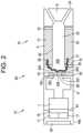
- FIG. 2is a cross-sectional view of an electronic vaping device according to at least one example embodiment.
- FIG. 3is a cross-sectional view of an electronic vaping device according to at least one example embodiment.
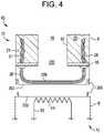
- FIG. 4is a cross-sectional view of an electronic vaping device according to at least one example embodiment.
- FIG. 5illustrates an embodiment of a magnetic, electrically conductive and resistive heater element and wick arrangement according to at least one example embodiment.
- FIG. 6illustrates current density through a cross section of the magnetic, electrically conductive and resistive heater element according to at least one example embodiment.
- first, second, third, etc.may be used herein to describe various elements, components, regions, layers and/or sections, these elements, components, regions, layers, and/or sections should not be limited by these terms. These terms are only used to distinguish one element, component, region, layer, or section from another region, layer, or section. Thus, a first element, component, region, layer, or section discussed below could be termed a second element, component, region, layer, or section without departing from the teachings of example embodiments.
- spatially relative termse.g., “beneath,” “below,” “lower,” “above,” “upper,” and the like
- the spatially relative termsare intended to encompass different orientations of the device in use or operation in addition to the orientation depicted in the figures. For example, if the device in the figures is turned over, elements described as “below” or “beneath” other elements or features would then be oriented “above” the other elements or features. Thus, the term “below” may encompass both an orientation of above and below.
- the devicemay be otherwise oriented (rotated 90 degrees or at other orientations) and the spatially relative descriptors used herein interpreted accordingly.
- Example embodimentsare described herein with reference to cross-sectional illustrations that are schematic illustrations of idealized embodiments (and intermediate structures) of example embodiments. As such, variations from the shapes of the illustrations as a result, for example, of manufacturing techniques and/or tolerances, are to be expected. Thus, example embodiments should not be construed as limited to the shapes of regions illustrated herein but are to include deviations in shapes that result, for example, from manufacturing. The regions illustrated in the figures are schematic in nature and their shapes are not intended to illustrate the actual shape of a region of a device and are not intended to limit the scope of example embodiments.
- At least one example embodimentis related to an electronic vaping device including a magnetic heater element.
- an electronic vaping device 60comprises a reservoir component (first or cartridge section) 70 and a power supply component (battery section) 72 .
- the power supply componentmay be reusable.
- the reservoir component 70includes an outer housing 6 extending in a longitudinal direction, an air inlet 44 , a vapor outlet 24 , an air passage, such as a central air passage 20 , communicating with the air inlet 44 and the vapor outlet 24 , and a reservoir 22 .
- a magnetic, electrically conductive and resistive heater element 99(hereinafter “magnetic heater element 99 ”) made of a magnetic material is located adjacent the air passage wherein the magnetic heater element 99 is in electrical communication with an alternator 11 through leads 83 .
- the alternator 11is configured to drive the magnetic heater element 99 with an alternating current when the alternator 11 is powered by a power source 1 included in the power supply component 72 .
- the outer housing 6 and/or the inner tube 62may be formed of any suitable material or combination of materials.
- suitable materialsinclude metals, alloys, plastics or composite materials containing one or more of those materials, or thermoplastics that are suitable for food or pharmaceutical applications, for example polypropylene, polyetheretherketone (PEEK), ceramic, and polyethylene.
- PEEKpolyetheretherketone
- the materialis light and non-brittle.
- the reservoir component 70may also include a mouth-end insert, such as a multi-port mouth-end insert 8 having two or more, off-axis, diverging outlets 24 .
- the mouth-end insert 8may include four outlets 24 .
- the mouth-end insert 8may have a single outlet 24 .
- the mouth-end insert 8is in fluid communication with the central air passage 20 .
- the electronic vaping device 60is about the same size as a cigarette.
- the electronic vaping device 60may be about 80 mm to about 110 mm long, or about 80 mm to about 100 mm long, and up to about 10 mm or greater in diameter.
- the electronic vaping deviceis about 84 mm long and has a diameter of about 7.8 mm.
- the electronic vaping device 60may be in a size and form approximating a cigar or a pipe.
- the reservoir component 70includes the magnetic heater element 99 .
- the power supply component 72includes the magnetic heater element 99 .
- a wick 28is in communication with the reservoir 22 .
- the wick 28is configured to draw a pre-vapor formulation from the reservoir 22 toward the magnetic heater element 99 .
- the magnetic heater element 99is configured to heat the pre-vapor formulation to a temperature sufficient to vaporize the pre-vapor formulation and form a vapor in the air passage (e.g., central air passage 20 ) when the magnetic heater element 99 is driven by the alternator 11 .
- the alternator 11is configured to drive the magnetic heater element 99 with the alternating current such that a current density of the alternating current through the magnetic heater element 99 concentrates at an outer surface thereof, which causes the outer surface to increase to a temperature sufficient to vaporize the pre-vapor formulation and form a vapor in the air passage (e.g. the central air passage 20 ) when powered by the power source 1 .
- a pre-vapor formulationis a material or combination of materials that may be transformed into a vapor.
- the pre-vapor formulationmay be a liquid, solid, and/or gel formulation including, but not limited to, water, beads, solvents, active ingredients, ethanol, plant extracts, natural or artificial flavors, and/or vapor formers such as glycerine and propylene glycol.
- the pre-vapor formulationhas a boiling point suitable for use in the electronic vaping device 60 . If the boiling point is too high, the magnetic heater element 99 will not be able to vaporize the pre-vapor formulation in the wick 28 . However, if the boiling point is too low, the pre-vapor formulation may vaporize prematurely without the magnetic heater element 99 being activated.
- the reservoir component 70may be disposable.
- the reservoir component 70may be connectable to the reusable power supply component 72 at a connection 205 .
- the connection 205may be a threaded connection or by any other suitable connection, such as a snug-fit, detent, clamp, clasp and/or magnetic connection.
- the alternator 11 of the power supply component 72is configured to generate the alternating current, when powered by the power source 1 , such that current density through the magnetic heater element 99 concentrates towards an outer surface of the magnetic heater element 99 and resistively heats the outer surface of the magnetic heater element 99 to a temperature sufficient to vaporize the pre-vapor formulation being drawn towards the magnetic heater element 99 and form a vapor in the air passage.
- the reservoir component 70comprises the outer housing 6 (such as a cylindrical outer tube or first outer housing), which extends longitudinally.
- the outer housing 6includes one or more air inlets 44 .
- the air inlets 44may extend through the connection 205 such that air is supplied to an interior of the outer housing 6 .
- An inner tube 62 disposed within the outer housing 6defines the central air passage 20 .
- the central air passage 20is straight and communicates with the one or more air inlets 44 and a vapor outlet 24 .
- the air inlets 44are located at different locations along the length and/or around the circumference of the electronic vaping device 60 . Further, altering the size and number of air inlets 44 may also aid in establishing a desired resistance to draw of the electronic vaping device 60 , and reduce generation of a whistling noise during a draw on the electronic vaping device 60 .
- each air inlet 44may comprise a beveled entrance and an angled passageway.
- the electronic vaping device 60includes a pair of air inlets 44 .
- Each of the air inlets 44may be angled toward the mouth end of the electronic vaping device 60 at an angle in the range of about 35° to about 55° with respect to the longitudinal axis of the article 60 , about 40° to about 50°, or about 45°.
- Such arrangement of air inlets 44minimizes (abates) and/or reduces “whistling” noise during a draw on the electronic vaping device 60 .
- a reservoir 22is established in an annular space between the outer housing 6 and the inner tube 62 .
- the annular spaceis sealed by a first seal 15 and a second seal (or stopper) 10 .
- the reservoir 22contains the pre-vapor formulation, and optionally, a storage medium 21 (i.e., fibrous medium).
- the storage medium 21is configured to disperse the pre-vapor formulation in the reservoir 22 .
- the storage medium 21may include one or more layers of gauze wrapped about the inner tube 62 .
- the storage medium 21comprises an outer wrapping of gauze surrounding an inner wrapping of gauze of the same or different material.
- the storage medium 21 of the reservoir 22is constructed from an alumina ceramic in the form of loose particles, loose fibers, or woven or nonwoven fibers.
- the storage medium 21is constructed from a cellulosic material such as cotton or gauze material or a polymer material, such as polyethylene terephthalate.
- the polymer materialmay be in the form of a woven fabric or in the form of a bundle of loose fibers.
- the storage medium 21may be a sintered, porous, or foamed material.
- the storage medium 21comprises a fibrous material comprising cotton, polyethylene, polyester, rayon and combinations thereof. Fibers of the fibrous material have a diameter ranging in size from about 6 microns to about 15 microns (e.g., about 8 microns to about 12 microns or about 9 microns to about 11 microns). Also, the fibers are sized to be irrespirable and may have a cross-section which has a y-shape, cross shape, clover shape or any other suitable shape. In at least one example embodiment, the reservoir 22 may comprise a filled tank lacking a storage medium 21 .
- the wick 28may be constructed of a flexible, filamentary material.
- the wick 28comprises a plurality of filaments having sufficient capillarity via interstitial spaces between the filaments to draw pre-vapor formulation from the reservoir 22 toward the magnetic heater element 99 .
- the wick 28may comprise a bundle of glass, ceramic, or metal filaments.
- the wick 28may comprise windings of filaments wound together into separate bundles or strands, and the wick 28 comprises a plurality of such bundles.
- the wick 28may include three or more bundles or strands of wound fiberglass filaments.
- the wick 28may be a porous body.
- the wick 28may include filaments having a cross-section that is generally cross-shaped, clover-shaped, Y-shaped, or any other suitable shape.
- the wick 28includes any suitable material or combination of materials.
- suitable materialsare glass filaments, fiberglass filaments, and ceramic, metal, or graphite based materials.
- the wick 28may have any suitable capillarity to accommodate pre-vapor formulations having different physical properties such as density, viscosity, surface tension, and vapor pressure.
- the capillarity properties of the wick 28 and the properties of the pre-vapor formulationare selected such that the wick 28 is always wet in the area adjacent the magnetic heater element 99 to avoid overheating of the magnetic heater element 99 and/or the wick 28 .
- wick arrangementOne advantage of the wick arrangement is that the pre-vapor formulation in the reservoir 22 is protected from oxygen (because oxygen cannot generally enter the reservoir 22 via the wick) so that the risk of degradation of the pre-vapor formulation is significantly reduced. Moreover, by using an opaque outer housing 6 , the reservoir 22 is protected from light so that the risk of degradation of the pre-vapor formulation is significantly reduced. Thus, a high level of shelf-life and cleanliness may be maintained.
- the magnetic heater element 99may be a wire coil, which at least partially surrounds the wick 28 .
- the wire coilmay extend fully or partially around the circumference of the wick 28 with or without spacing between the turns of the coil.
- the wire coilmay contact the wick 28 .
- the magnetic heater element 99is not in contact with the wick 28 .
- the magnetic heater element 99is located adjacent to (in thermal communication with) the wick 28 .
- the magnetic heater element 99is configured to heat pre-vapor formulation on and/or in the wick 28 to a temperature sufficient to vaporize the pre-vapor formulation and form a vapor.
- the magnetic heater element 99is formed from an alloy including nickel, iron, molybdenum, chromium, aluminum, copper, or combinations thereof. In at least one example embodiment, the magnetic heater element 99 may be formed from a permalloy-based magnetic material. In embodiments, the magnetic heater element 99 may be formed from a Mu-metal. The magnetic heater element 99 may have a circular cross-section and may have a diameter of about 0.2 mm to about 0.5 mm. The magnetic heater element 99 may have an end to end length of about 4 mm to about 25 mm. The magnetic heater element 99 may be U-shaped or sinuously shaped. Other cross-sectional shapes and external forms may be employed. In at least one example embodiment, the magnetic heater element 99 may have an elongate planar form with a rectangular cross-section.
- the wick 28includes a transverse middle portion 228 , which extends across and/or is adjacent to an opening in the first seal 15 and an inlet portion 230 of the central air passage 20 .
- the wick 28may include a first end portion 29 and a second end portion 31 .
- the first end portion 29 and the second end portion 31extend longitudinally through the first seal 15 into the confines of the reservoir 22 so as to contact the pre-vapor formulation in the reservoir 22 .
- Notchesmay be provided at locations along the perimeter of the first seal 15 to accommodate placement of the end portions 29 , 31 of the wick 28 .
- the wick 28may include only one end portion 29 in communication with the reservoir, and that the placement and routing of the portions of the wick 28 may be other than as described, so long as pre-vapor formulation is drawn from the reservoir 22 into proximate relation with the magnetic heater element 99 by the wick 28 .
- the magnetic heater element 99is in thermal communication with the wick 28 , and heats the pre-vapor formulation in the wick 28 by thermal conduction and convection. In at least one example embodiment, heat from the magnetic heater element 99 may be transferred to a stream of incoming ambient air that is drawn through the electronic vaping device 60 during use to form heated air that heats the vapour precursor by convection alone.
- the magnetic heater element 99is located adjacent the inlet portion 230 of the central channel 20 so as to promote fuller vapor formation by providing a generally straight flow path from the location of the magnetic heater element 99 to the interior of the multi-port mouth end insert 8 .
- Such an arrangementmay avoid and/or reduce abrupt changes in direction of air flow and vapor flow, and avoids associated losses due to impaction and other effects, which may otherwise impede vapor development and production.
- the central air passage 20minimizes and/or reduces contact and thermal transfer between the vapor and the walls of the reservoir 22 formed by the inner tube 62 .
- the power supply component 72includes an outer housing 6 ′ (second outer housing) extending in a longitudinal direction and includes the power source 1 , such as a battery, in electrical communication with the magnetic heater element 99 through the alternator 11 and control circuitry 16 .
- the power source 1such as a battery
- the control circuitry 16includes the alternator 11 .
- the alternator 11is configured to drive the magnetic heater element 99 by producing an alternating current when powered by the power supply 1 thereby causing the magnetic heater element 99 to resistively heat to a desired (or, alternatively a predetermined) temperature for a desired (or, alternatively a predetermined) time period.
- the alternator 11provides an alternating current at a frequency of about 100 kHz to about 1 MHz wherein the frequency is selected based upon parameters of the magnetic heater element 99 , such as the makeup (composition) and/or a cross-sectional diameter or shape of the magnetic heater element 99 .
- the control circuitry 16communicates responsively with a sensor (e.g., pressure sensor) 17 that is located at a distal end portion of the power supply component 72 .
- the sensor 17is configured to generate a signal responsive to air being drawn from the electronic vaping device 60 through the vapor outlet 24 .
- the control circuitry 16communicates an alternating power cycle from the alternator 11 , such that the alternator 11 drives the magnetic heater element 99 with an alternating current and current density through the magnetic heater element 99 concentrates at an outer surface of the magnetic heater element 99 to resistively heat the outer surface of the magnetic heater element 99 .
- the pressure drop of a draw (or puff) upon the mouth-end insert 8 of the reservoir component 70is communicated to the sensor 17 through openings 44 b and 44 c in components 70 and 72 , respectively, adjacent the connector 205 , and via spaces provided between the power source 1 and adjacent portions of the outer housing 6 of the power supply component 72 .
- a partition 61is provided at or adjacent the sensor 17 to isolate a pressure relief inlet 44 a which is located at the distal end of the power supply component 72 .
- the pressure relief inlet 44 aserves to relieve pressure on its side of the sensor 17 , which would otherwise interfere with facile operation of the sensor 17 .
- the sensor 17 and control circuitry 16may be a single chip.
- the chipmay be an integrated circuit with resistors and timing circuits, inputs and outputs which may function to cause switching (i.e., supply power from the power source to the leads based on the puff sensor signal, and to cause an LED 48 to blink when power is low, etc.).
- the control circuitry 16may be configured to provide a power cycle that achieves optimal ramp-up in temperature of the magnetic heater element 99 and maintenance of an operating temperature for a desired (or, alternatively a predetermined) period of time.
- the power cyclemay be divided into two (or more) phases each having a respective time period of T 1 and T 2 .
- T 1a higher frequency and magnitude of alternating current may be employed so as to rapidly cause the magnetic heater element 99 to heat.
- the control circuitry 16may provide a power cycle with a more moderate frequency and/or a more moderate magnitude of alternating current so as to achieve steady heating effect throughout the second phase (T 2 ).
- the power cyclescould include a plurality of phases, such that only the amplitude or only the frequency is varied, and may include phases wherein there is no power and/or alternating current being directed through the magnetic heater element 99 .
- the control circuitry 16is configured to adjust frequency, magnitude, and/or time period responsive to readings of battery voltage of the power supply 1 so that consistent performance is maintained as the voltage level of the power supply (i.e. battery) 1 declines during use.
- the puff sensor 17is configured to generate more than one signal, such as a range of signals responsive to the magnitude of a puff or draw upon the mouth-end insert 8 so that the control circuitry 16 may discriminate between the signals to adjust the frequency, magnitude, and/or time of the immediate power cycle in response to the signal it receives from the puff sensor 17 .
- a heavy drawmight generate a first signal from the puff sensor 17 , which in turn would cause the control circuitry to extend the time of the immediate power cycle responsively or make some other adjustment in the power cycle to provide a greater production of vapor.
- the magnetic heater element 99When activated, the magnetic heater element 99 heats a portion of the wick 28 in thermal communication with the magnetic heater element 99 for less than about 10 seconds or less than about 7 seconds.
- the power cycle(or maximum puff length) may range in period from about 2 seconds to about 10 seconds (e.g., about 3 seconds to about 9 seconds, about 4 seconds to about 8 seconds, or about 5 seconds to about 7 seconds).
- control circuitry 16may include a manually operable switch for an individual to initiate a puff.
- the time-period and characteristics of the alternating current supplied to the magnetic heater element 99may be pre-set depending on the amount of pre-vapor formulation desired to be vaporized.
- the control circuitry 16may be pre-programmed or programmable for this purpose.
- the control circuitry 16may be configured to power the alternator 11 to drive the magnetic heater element 99 for as long as the puff sensor 17 detects a pressure drop.
- Having a separate reservoir component 70 and power supply component 72allows the wick 28 and reservoir 22 to be disposed of when the reservoir component 70 is depleted, and allows the power supply component 72 to be reusable. Thus, there will be no cross-contamination between different mouth-end inserts 8 , for example, when using different pre-vapor formulations. Also, if the reservoir component 70 is replaced at suitable intervals, there is little chance of the wick 28 becoming clogged with pre-vapor formulation.
- the battery or power source 1may be a lithium-ion battery or one of its variants, for example a lithium-ion polymer battery.
- the batterymay be a nickel-metal hydride battery, a nickel cadmium battery, a lithium-manganese battery, a lithium-cobalt battery, or a fuel cell.
- the electronic vaping device 60is vapable by an adult vaper until the energy in the power source 1 is depleted.
- the power source 1may be rechargeable and include circuitry allowing the battery to be chargeable by an external charging device. In that case, the circuitry, when charged, provides power for a pre-determined number of puffs, after which the circuitry must be re-connected to an external charging device.
- the control circuitry 16may also include a light emitting diode (LED) 48 configured to glow when the magnetic heater element 99 is activated.
- the LED 48is at a distal end of the electronic vaping device 60 so that the LED 48 mimics the appearance of a burning coal during a puff.
- the LED 48may be arranged to be visible to the smoker.
- the LED 48may be utilized for electronic vaping device system diagnostics.
- the LED 48may also be configured such that an individual may activate and/or deactivate the LED 48 for privacy, such that the LED 48 would not activate during use of the electronic vaping device if desired.
- FIG. 1illustrates an exploded view of the connection between the reservoir component 70 and the power supply component 72 as illustrated in FIG. 1 .
- the reservoir component 70may be connectable to the power supply component at the connection 205 .
- electrical contacts 108 of the reservoir component 70electrically connect to electrical contacts 109 of the power supply component 72 .
- the electrical contacts 108 of the reservoir component 70protrude from a seal end 263 of the reservoir component 70 and electrical contacts 109 of the power supply component 72 protrude from a seal end 233 of the power supply component 72 such that they may mate when the power supply component 72 and the reservoir component 70 are connected.
- the seal end 233 of the power supply component 72 and the seal end 263 of the reservoir component 70are formed of electrically insulating material.
- the electrical contacts 108 of the reservoir component 70are in electrical communication with the magnetic heater element 99 through leads 83 and the electrical contacts 109 of the power supply component are in electrical communication with the power source 1 , through the control circuitry 16 , puff sensor 17 , and alternator 11 such that a magnetic heater element circuit is formed when the reservoir component 70 and the power supply component 72 are connected.
- the magnetic heater element 99may be included in the power supply component 72 .
- FIG. 4illustrates an exploded view of the connection between the reservoir component 70 and the power supply component 72 as illustrated in FIG. 2 .
- the reservoir component 70may be connectable to the power supply component at the connection 205 .
- the power supply component 72includes the magnetic heater element 99 in electrical communication with the power source 1 , the control circuitry 16 , the puff sensor 17 and the alternator 11 through leads 83 .
- the power supply componentincludes a seal end 233 .
- the seal end 233directly contacts a seal end 263 of the reservoir component 70 when the reservoir component 70 is connected to the power supply component 72 such that the seal ends 233 and 263 are formed of thermally conductive material.
- heat generated by that magnetic heater element 99may be thermally transferred from the power supply component 72 to the wick 28 included in the reservoir component 70 .
- the magnetic heater element 99physically contacts the seal end 233 of the power supply component 72 and the wick physically contacts the seal end 263 of the reservoir component 70 such that heat may be directly conducted from the magnetic heater element 99 through the seal ends 233 , 263 to the pre-vapor formulation contained on the wick 28 so as to vaporize the pre-vapor formulation on the wick 28 .
- a portion of the magnetic heater element 99may protrude through the seal end 233 and directing contact the seal 263 of the reservoir component so that heat may be directly conducted from the magnetic heater element 99 through the seal end 263 to the pre-vapor formulation contained on the wick 28 , and the pre-vapor formulation on the wick 28 may be vaporized.
- the magnetic heater element 99is adjacent a wick 28 .
- leads 83are electrically connected to the magnetic heater element 99 such that the leads 83 may electrically connect the magnetic heater element 99 to the power supply 1 , control circuitry 16 , puff sensor 17 , and alternator 11 .
- the magnetic heater element 99has a sinuous shape which extends along a length of a transverse portion 228 of the wick 28 .
- the wick 28may directly contact a portion of the magnetic heater element 99 .
- the magnetic heater element 99may be U-shaped, rectangular in cross-section, or have another form.
- the magnetic heater element 99has a high relative magnetic permeability of about 1,000 or greater (wherein wood has a value of 1 and pure iron has a value of 200,000).
- FIG. 6illustrates current density through a cross section of the magnetic heater element 99 when the magnetic heater element 99 is driven by the alternating current supplied by the alternator 11 .
- the magnetic heater element 99has a circular cross-section.
- the current density 600 through the magnetic heater element 99concentrates at an outer surface 699 thereof due to the skin effect.
- Skin effectis the tendency for an alternating current to concentrate at or near the outer part or “skin” of a conductor, such as the outer surface 699 of the magnetic heater element 99 .
- the alternating currentis supplied through the magnetic heater element 99 , the current is displaced more and more to the outer surface 699 as the frequency of the alternating current increases.
- a mathematical description of skin effectmay be derived from Maxwell's equations, for simple shapes, including cylindrical, tubular and flat conductors, each of which may be used as the cross sectional shape of the magnetic heater element 99 .
- Maxwell's equationsfor simple shapes, including cylindrical, tubular and flat conductors, each of which may be used as the cross sectional shape of the magnetic heater element 99 .
- the current densityis a maximum at the surface and its magnitude decreases exponentially with distance into the conductor.
- the skin depth or penetration depth 6is frequently used in assessing the results of skin effect.
- skin depthis the depth below the conductor surface at which the current density has decreased to 1/e (approximately 37%) of its value at the surface and is given by Equation 1, shown below, wherein p is the resistivity of the conductor, ⁇ is the angular frequency of the current, and ⁇ is the absolute magnetic permeability of the conductor.
- Equation 1This concept applies to plane solids, but may be extended to other shapes provided the radius of curvature of the conductor surface is appreciably greater than ⁇ .
- ⁇(2 p / ⁇ ) 1/2 Equation 1:
- the cross sectional diameter of the magnetic heater element 99is greater than the skin depth ( ⁇ ) 601 of the magnetic heater element 99 .
- the magnetic heater elementmay be made with a larger cross sectional area and is therefore more rugged and manageable so as to facilitate handling and automated manufacturing.
- the teachingsmay lead to enhanced operational efficiencies, because surface portions of the magnetic heater element adjacent the pre-vapor formulation are heated.
Landscapes
- Engineering & Computer Science (AREA)
- Physics & Mathematics (AREA)
- Electromagnetism (AREA)
- Mechanical Engineering (AREA)
- Sustainable Energy (AREA)
- Thermal Sciences (AREA)
- Life Sciences & Earth Sciences (AREA)
- General Engineering & Computer Science (AREA)
- Sustainable Development (AREA)
- Resistance Heating (AREA)
- Catching Or Destruction (AREA)
- General Induction Heating (AREA)
- Air-Conditioning For Vehicles (AREA)
- Details Of Connecting Devices For Male And Female Coupling (AREA)
- Irons (AREA)
Abstract
Description
δ=(2p/ωμ)1/2 Equation 1:
Claims (10)
Priority Applications (3)
| Application Number | Priority Date | Filing Date | Title |
|---|---|---|---|
| US14/882,665US11578863B2 (en) | 2014-10-15 | 2015-10-14 | Electronic vaping device and components thereof |
| US18/162,908US12092321B2 (en) | 2014-10-15 | 2023-02-01 | Electronic vaping device and components thereof |
| US18/808,221US20240410568A1 (en) | 2014-10-15 | 2024-08-19 | Electronic vaping device and components thereof |
Applications Claiming Priority (2)
| Application Number | Priority Date | Filing Date | Title |
|---|---|---|---|
| US201462064065P | 2014-10-15 | 2014-10-15 | |
| US14/882,665US11578863B2 (en) | 2014-10-15 | 2015-10-14 | Electronic vaping device and components thereof |
Related Child Applications (1)
| Application Number | Title | Priority Date | Filing Date |
|---|---|---|---|
| US18/162,908DivisionUS12092321B2 (en) | 2014-10-15 | 2023-02-01 | Electronic vaping device and components thereof |
Publications (2)
| Publication Number | Publication Date |
|---|---|
| US20160109115A1 US20160109115A1 (en) | 2016-04-21 |
| US11578863B2true US11578863B2 (en) | 2023-02-14 |
Family
ID=55747241
Family Applications (3)
| Application Number | Title | Priority Date | Filing Date |
|---|---|---|---|
| US14/882,665Active2038-06-21US11578863B2 (en) | 2014-10-15 | 2015-10-14 | Electronic vaping device and components thereof |
| US18/162,908ActiveUS12092321B2 (en) | 2014-10-15 | 2023-02-01 | Electronic vaping device and components thereof |
| US18/808,221PendingUS20240410568A1 (en) | 2014-10-15 | 2024-08-19 | Electronic vaping device and components thereof |
Family Applications After (2)
| Application Number | Title | Priority Date | Filing Date |
|---|---|---|---|
| US18/162,908ActiveUS12092321B2 (en) | 2014-10-15 | 2023-02-01 | Electronic vaping device and components thereof |
| US18/808,221PendingUS20240410568A1 (en) | 2014-10-15 | 2024-08-19 | Electronic vaping device and components thereof |
Country Status (9)
| Country | Link |
|---|---|
| US (3) | US11578863B2 (en) |
| EP (1) | EP3206515A4 (en) |
| CN (1) | CN107072315B (en) |
| EA (1) | EA201790835A1 (en) |
| IL (3) | IL251279B2 (en) |
| MY (1) | MY197594A (en) |
| UA (1) | UA123625C2 (en) |
| WO (1) | WO2016061166A1 (en) |
| ZA (2) | ZA201701981B (en) |
Cited By (2)
| Publication number | Priority date | Publication date | Assignee | Title |
|---|---|---|---|---|
| US20210227885A1 (en)* | 2017-04-25 | 2021-07-29 | Nerudia Limited | Aerosol Delivery System |
| US12092321B2 (en) | 2014-10-15 | 2024-09-17 | Altria Client Services Llc | Electronic vaping device and components thereof |
Families Citing this family (64)
| Publication number | Priority date | Publication date | Assignee | Title |
|---|---|---|---|---|
| US20160345631A1 (en) | 2005-07-19 | 2016-12-01 | James Monsees | Portable devices for generating an inhalable vapor |
| US10279934B2 (en) | 2013-03-15 | 2019-05-07 | Juul Labs, Inc. | Fillable vaporizer cartridge and method of filling |
| CN105263345A (en) | 2013-05-06 | 2016-01-20 | 派克斯实验公司 | Nicotine salt formulations for aerosol devices and methods thereof |
| US10039321B2 (en) | 2013-11-12 | 2018-08-07 | Vmr Products Llc | Vaporizer |
| KR20240070710A (en) | 2013-12-05 | 2024-05-21 | 쥴 랩스, 인크. | Nicotine liquid formulations for aerosol devices and methods thereof |
| US20160366947A1 (en) | 2013-12-23 | 2016-12-22 | James Monsees | Vaporizer apparatus |
| US10159282B2 (en) | 2013-12-23 | 2018-12-25 | Juul Labs, Inc. | Cartridge for use with a vaporizer device |
| DE202014011260U1 (en) | 2013-12-23 | 2018-11-13 | Juul Labs Uk Holdco Limited | Systems for an evaporation device |
| US9549573B2 (en) | 2013-12-23 | 2017-01-24 | Pax Labs, Inc. | Vaporization device systems and methods |
| US10076139B2 (en) | 2013-12-23 | 2018-09-18 | Juul Labs, Inc. | Vaporizer apparatus |
| USD825102S1 (en) | 2016-07-28 | 2018-08-07 | Juul Labs, Inc. | Vaporizer device with cartridge |
| USD842536S1 (en) | 2016-07-28 | 2019-03-05 | Juul Labs, Inc. | Vaporizer cartridge |
| US10058129B2 (en) | 2013-12-23 | 2018-08-28 | Juul Labs, Inc. | Vaporization device systems and methods |
| WO2015175979A1 (en) | 2014-05-16 | 2015-11-19 | Pax Labs, Inc. | Systems and methods for aerosolizing a smokeable material |
| MX394125B (en) | 2014-12-05 | 2025-03-24 | Juul Labs Inc | CALIBRATED DOSE CONTROL |
| US9943111B2 (en)* | 2015-08-31 | 2018-04-17 | Lunatech, Llc | Methods and systems for vapor cooling |
| US9936737B2 (en)* | 2015-10-28 | 2018-04-10 | Lunatech, Llc | Methods and systems for a dual function vapor device |
| WO2017087612A1 (en)* | 2015-11-17 | 2017-05-26 | John Cameron | Portable wireless electronic vapor device |
| US9936738B2 (en)* | 2015-11-17 | 2018-04-10 | Lunatech, Llc | Methods and systems for smooth vapor delivery |
| EP3413960B1 (en) | 2016-02-11 | 2021-03-31 | Juul Labs, Inc. | Fillable vaporizer cartridge and method of filling |
| CO2018009342A2 (en) | 2016-02-11 | 2018-09-20 | Juul Labs Inc | Secure fixing cartridges for vaporizing devices |
| US10433580B2 (en) | 2016-03-03 | 2019-10-08 | Altria Client Services Llc | Methods to add menthol, botanic materials, and/or non-botanic materials to a cartridge, and/or an electronic vaping device including the cartridge |
| US10455863B2 (en) | 2016-03-03 | 2019-10-29 | Altria Client Services Llc | Cartridge for electronic vaping device |
| US10368580B2 (en)* | 2016-03-08 | 2019-08-06 | Altria Client Services Llc | Combined cartridge for electronic vaping device |
| US10405582B2 (en) | 2016-03-10 | 2019-09-10 | Pax Labs, Inc. | Vaporization device with lip sensing |
| US10357060B2 (en) | 2016-03-11 | 2019-07-23 | Altria Client Services Llc | E-vaping device cartridge holder |
| US10368581B2 (en) | 2016-03-11 | 2019-08-06 | Altria Client Services Llc | Multiple dispersion generator e-vaping device |
| GB201605105D0 (en) | 2016-03-24 | 2016-05-11 | Nicoventures Holdings Ltd | Vapour provision apparatus |
| GB201605101D0 (en) | 2016-03-24 | 2016-05-11 | Nicoventures Holdings Ltd | Electronic vapour provision system |
| GB201605100D0 (en) | 2016-03-24 | 2016-05-11 | Nicoventures Holdings Ltd | Vapour provision system |
| USD849996S1 (en) | 2016-06-16 | 2019-05-28 | Pax Labs, Inc. | Vaporizer cartridge |
| USD836541S1 (en) | 2016-06-23 | 2018-12-25 | Pax Labs, Inc. | Charging device |
| USD848057S1 (en) | 2016-06-23 | 2019-05-07 | Pax Labs, Inc. | Lid for a vaporizer |
| USD851830S1 (en) | 2016-06-23 | 2019-06-18 | Pax Labs, Inc. | Combined vaporizer tamp and pick tool |
| US10292426B2 (en)* | 2016-06-24 | 2019-05-21 | Altria Client Services, Llc | E-vaping device cartridge with superabsorbent polymer |
| US10051894B2 (en)* | 2016-08-01 | 2018-08-21 | Altria Client Services Llc | Cartridge and e-vaping device with serpentine heater |
| US10143239B2 (en) | 2016-08-01 | 2018-12-04 | Altria Client Services Llc | Cartridge and e-vaping device |
| US11660403B2 (en) | 2016-09-22 | 2023-05-30 | Juul Labs, Inc. | Leak-resistant vaporizer device |
| US20220071285A1 (en)* | 2019-03-21 | 2022-03-10 | Nerudia Limited | Aerosol delivery system |
| EP3711611A1 (en)* | 2019-03-21 | 2020-09-23 | Nerudia Limited | Aerosol delivery system |
| EP3711608A1 (en)* | 2019-03-21 | 2020-09-23 | Nerudia Limited | Aerosol delivery system |
| JP7112427B2 (en)* | 2017-06-28 | 2022-08-03 | フィリップ・モーリス・プロダクツ・ソシエテ・アノニム | Electrical heating assembly, aerosol generator and method for resistively heating an aerosol-forming substrate |
| US11523469B2 (en) | 2017-06-28 | 2022-12-06 | Philip Morris Products S.A. | Electrical heating assembly, aerosol-generating device and method for resistively heating an aerosol-forming substrate |
| EP3675661B1 (en) | 2017-08-28 | 2023-06-07 | Juul Labs, Inc. | Wick for vaporizer device |
| GB201714300D0 (en)* | 2017-09-06 | 2017-10-18 | British American Tobacco Investments Ltd | Vapour provision systems |
| USD887632S1 (en) | 2017-09-14 | 2020-06-16 | Pax Labs, Inc. | Vaporizer cartridge |
| KR20200043473A (en)* | 2017-09-27 | 2020-04-27 | 니뽄 다바코 산교 가부시키가이샤 | Battery unit and flavor aspirator |
| KR102551348B1 (en) | 2017-12-28 | 2023-07-05 | 제이티 인터내셔널 소시에떼 아노님 | Induction Heating Assemblies for Steam Generators |
| US10959459B2 (en)* | 2018-05-16 | 2021-03-30 | Rai Strategic Holdings, Inc. | Voltage regulator for an aerosol delivery device |
| CN110754696A (en) | 2018-07-23 | 2020-02-07 | 尤尔实验室有限公司 | Airflow management for evaporator units |
| CN119632302A (en) | 2018-07-31 | 2025-03-18 | 尤尔实验室有限公司 | Cartridge-based heat-without-burn vaporizer |
| WO2020064682A1 (en) | 2018-09-25 | 2020-04-02 | Philip Morris Products S.A. | Inductively heatable aerosol-generating article comprising an aerosol-forming substrate and a susceptor assembly |
| IL281655B2 (en) | 2018-09-25 | 2024-08-01 | Philip Morris Products Sa | Susceptor assembly for inductively heating an aerosol-forming substrate |
| EP3855955B1 (en) | 2018-09-25 | 2022-09-07 | Philip Morris Products S.A. | Inductively heating aerosol-generating device comprising a susceptor assembly |
| JP7508464B2 (en) | 2018-09-25 | 2024-07-01 | フィリップ・モーリス・プロダクツ・ソシエテ・アノニム | INDUCTION HEATING ASSEMBLY FOR INDUCTION HEATING AN AEROSOL-FORMING SUBSTRATE - Patent application |
| KR20210064307A (en) | 2018-09-25 | 2021-06-02 | 필립모리스 프로덕츠 에스.에이. | Method for inductive heating of heating assemblies and aerosol-forming substrates |
| US12256784B2 (en) | 2018-10-17 | 2025-03-25 | Juul Labs, Inc. | Cartridge for a vaporizer device |
| EP3876763B1 (en) | 2018-11-05 | 2022-12-28 | Juul Labs, Inc. | A cartridge for a vaporizer device |
| JP7660503B2 (en) | 2018-11-05 | 2025-04-11 | ジュール・ラブズ・インコーポレイテッド | Cartridges for vaporizer devices |
| GB201818080D0 (en)* | 2018-11-06 | 2018-12-19 | Nicoventures Trading Ltd | Vapour provision systems |
| CN110226776A (en)* | 2019-06-19 | 2019-09-13 | 深圳市精渡科技有限公司 | Electronic cigarette and its temperature control method, device and computer readable storage medium |
| WO2021228910A1 (en)* | 2020-05-15 | 2021-11-18 | Philip Morris Products S.A. | Aerosol-generating article with liquid-conveying susceptor assembly |
| GB2622497B (en)* | 2021-07-19 | 2024-08-21 | Nicoventures Trading Ltd | Aerosol provision system |
| CN115670024B (en)* | 2021-07-29 | 2025-04-11 | 深圳麦克韦尔科技有限公司 | A heating element component, atomization component and electronic atomization device |
Citations (26)
| Publication number | Priority date | Publication date | Assignee | Title |
|---|---|---|---|---|
| EP0371645A1 (en) | 1988-11-29 | 1990-06-06 | The Whitaker Corporation | Self regulating temperature heater as an integral part of a printed circuit board |
| US5388594A (en)* | 1991-03-11 | 1995-02-14 | Philip Morris Incorporated | Electrical smoking system for delivering flavors and method for making same |
| EP0703735A1 (en) | 1994-04-08 | 1996-04-03 | Philip Morris Products Inc. | Inductive heating systems for smoking articles |
| US5878752A (en) | 1996-11-25 | 1999-03-09 | Philip Morris Incorporated | Method and apparatus for using, cleaning, and maintaining electrical heat sources and lighters useful in smoking systems and other apparatuses |
| DE69724559T2 (en) | 1996-06-17 | 2004-07-15 | Japan Tobacco Inc. | FLAVORED ARTICLE |
| US20060193611A1 (en)* | 2005-02-03 | 2006-08-31 | Zobele Espana, S.A. | Vaporizer device of multi-fragrance volatile substances |
| US7942147B2 (en) | 2001-06-05 | 2011-05-17 | Alexza Pharmaceuticals, Inc. | Aerosol forming device for use in inhalation therapy |
| EP2327318A1 (en) | 2009-11-27 | 2011-06-01 | Philip Morris Products S.A. | An electrically heated smoking system with internal or external heater |
| US20110226236A1 (en)* | 2008-10-23 | 2011-09-22 | Helmut Buchberger | Inhaler |
| US20120145702A1 (en)* | 2009-12-15 | 2012-06-14 | The Boeing Company | Smart heating blanket |
| US20120205361A1 (en)* | 2011-02-15 | 2012-08-16 | Asteer Co., Ltd. | Method of Heating Plated Steel Plate |
| US20130087160A1 (en)* | 2011-10-06 | 2013-04-11 | Alexandru Gherghe | Electronic pipe personal vaporizer with concealed removable atomizer/ cartomizer |
| US20130192623A1 (en) | 2012-01-31 | 2013-08-01 | Altria Client Services Inc. | Electronic cigarette |
| US20130192617A1 (en)* | 2012-01-30 | 2013-08-01 | Spencer Thompson | Cartomizer for electronic cigarettes |
| US20130206154A1 (en) | 2008-04-17 | 2013-08-15 | Philip Morris Usa Inc. | Electrically heated smoking system |
| US20130213419A1 (en)* | 2012-02-22 | 2013-08-22 | Altria Client Services Inc. | Electronic smoking article and improved heater element |
| US20130213418A1 (en) | 2012-02-22 | 2013-08-22 | Altria Client Services Inc. | Electronic smoking article |
| US20130340750A1 (en) | 2010-12-03 | 2013-12-26 | Philip Morris Products S.A. | Electrically Heated Aerosol Generating System Having Improved Heater Control |
| GB2504074A (en) | 2012-07-16 | 2014-01-22 | Nicoventures Holdings Ltd | Electronic cigarette |
| DE202013010986U1 (en) | 2013-12-13 | 2014-02-17 | Leslaw Piasecki | Electronic cigarette with power electronics for controlling the heating power of a heating element |
| US20140064714A1 (en) | 2012-06-11 | 2014-03-06 | The Procter & Gamble Company | Air treatment device for the vaporization of an air freshening substance |
| US20140074082A1 (en) | 2009-04-17 | 2014-03-13 | Domain Surgical, Inc. | System and method of controlling power delivery to a surgical instrument |
| CN103689812A (en) | 2013-12-30 | 2014-04-02 | 深圳市合元科技有限公司 | Smoke generator and electronic cigarette with same |
| CN203762288U (en) | 2013-12-30 | 2014-08-13 | 深圳市合元科技有限公司 | Atomization device applicable to solid tobacco materials and electronic cigarette |
| US20140238423A1 (en)* | 2013-02-22 | 2014-08-28 | Altria Client Services Inc. | Electronic smoking article |
| US20140270729A1 (en)* | 2013-03-15 | 2014-09-18 | R.J. Reynolds Tobacco Company | Heating elements formed from a sheet of a material and inputs and methods for the production of atomizers |
Family Cites Families (6)
| Publication number | Priority date | Publication date | Assignee | Title |
|---|---|---|---|---|
| US5249586A (en)* | 1991-03-11 | 1993-10-05 | Philip Morris Incorporated | Electrical smoking |
| CN1488301A (en)* | 2002-10-08 | 2004-04-14 | 陈伟军 | Stay-cord cigarette igniter withou fuel |
| US20100000980A1 (en)* | 2008-07-02 | 2010-01-07 | Bogdan Popescu | Induction Heating System with Versatile Inductive Cartridge |
| DE102013214647A1 (en) | 2012-07-30 | 2014-05-15 | Denso Corporation | linear solenoid |
| CN103960781A (en)* | 2013-09-29 | 2014-08-06 | 深圳市麦克韦尔科技有限公司 | Electronic cigarette |
| CN107072315B (en) | 2014-10-15 | 2021-07-02 | 奥驰亚客户服务有限责任公司 | Electronic cigarette device and its components |
- 2015
- 2015-10-14CNCN201580055849.1Apatent/CN107072315B/enactiveActive
- 2015-10-14USUS14/882,665patent/US11578863B2/enactiveActive
- 2015-10-14MYMYPI2017000490Apatent/MY197594A/enunknown
- 2015-10-14EPEP15851050.3Apatent/EP3206515A4/enactivePending
- 2015-10-14EAEA201790835Apatent/EA201790835A1/enunknown
- 2015-10-14ILIL251279Apatent/IL251279B2/enunknown
- 2015-10-14WOPCT/US2015/055429patent/WO2016061166A1/enactiveApplication Filing
- 2015-10-14ILIL321381Apatent/IL321381A/enunknown
- 2015-10-14UAUAA201704593Apatent/UA123625C2/enunknown
- 2015-10-14ILIL305650Apatent/IL305650B1/enunknown
- 2017
- 2017-03-22ZAZA2017/01981Apatent/ZA201701981B/enunknown
- 2023
- 2023-02-01USUS18/162,908patent/US12092321B2/enactiveActive
- 2023-03-16ZAZA2023/03637Apatent/ZA202303637B/enunknown
- 2024
- 2024-08-19USUS18/808,221patent/US20240410568A1/enactivePending
Patent Citations (28)
| Publication number | Priority date | Publication date | Assignee | Title |
|---|---|---|---|---|
| EP0371645A1 (en) | 1988-11-29 | 1990-06-06 | The Whitaker Corporation | Self regulating temperature heater as an integral part of a printed circuit board |
| US5388594A (en)* | 1991-03-11 | 1995-02-14 | Philip Morris Incorporated | Electrical smoking system for delivering flavors and method for making same |
| EP0703735A1 (en) | 1994-04-08 | 1996-04-03 | Philip Morris Products Inc. | Inductive heating systems for smoking articles |
| DE69724559T2 (en) | 1996-06-17 | 2004-07-15 | Japan Tobacco Inc. | FLAVORED ARTICLE |
| US5878752A (en) | 1996-11-25 | 1999-03-09 | Philip Morris Incorporated | Method and apparatus for using, cleaning, and maintaining electrical heat sources and lighters useful in smoking systems and other apparatuses |
| US7942147B2 (en) | 2001-06-05 | 2011-05-17 | Alexza Pharmaceuticals, Inc. | Aerosol forming device for use in inhalation therapy |
| US20060193611A1 (en)* | 2005-02-03 | 2006-08-31 | Zobele Espana, S.A. | Vaporizer device of multi-fragrance volatile substances |
| US20130206154A1 (en) | 2008-04-17 | 2013-08-15 | Philip Morris Usa Inc. | Electrically heated smoking system |
| US20110226236A1 (en)* | 2008-10-23 | 2011-09-22 | Helmut Buchberger | Inhaler |
| US20140074082A1 (en) | 2009-04-17 | 2014-03-13 | Domain Surgical, Inc. | System and method of controlling power delivery to a surgical instrument |
| US20110126848A1 (en)* | 2009-11-27 | 2011-06-02 | Philip Morris Usa Inc. | Electrically heated smoking system with internal or external heater |
| EP2327318A1 (en) | 2009-11-27 | 2011-06-01 | Philip Morris Products S.A. | An electrically heated smoking system with internal or external heater |
| US20120145702A1 (en)* | 2009-12-15 | 2012-06-14 | The Boeing Company | Smart heating blanket |
| US20130340750A1 (en) | 2010-12-03 | 2013-12-26 | Philip Morris Products S.A. | Electrically Heated Aerosol Generating System Having Improved Heater Control |
| US20120205361A1 (en)* | 2011-02-15 | 2012-08-16 | Asteer Co., Ltd. | Method of Heating Plated Steel Plate |
| US20130087160A1 (en)* | 2011-10-06 | 2013-04-11 | Alexandru Gherghe | Electronic pipe personal vaporizer with concealed removable atomizer/ cartomizer |
| US20130192617A1 (en)* | 2012-01-30 | 2013-08-01 | Spencer Thompson | Cartomizer for electronic cigarettes |
| US20130192615A1 (en)* | 2012-01-31 | 2013-08-01 | Altria Client Services Inc. | Electronic cigarette |
| US20130192623A1 (en) | 2012-01-31 | 2013-08-01 | Altria Client Services Inc. | Electronic cigarette |
| US20130213419A1 (en)* | 2012-02-22 | 2013-08-22 | Altria Client Services Inc. | Electronic smoking article and improved heater element |
| US20130213418A1 (en) | 2012-02-22 | 2013-08-22 | Altria Client Services Inc. | Electronic smoking article |
| US20140064714A1 (en) | 2012-06-11 | 2014-03-06 | The Procter & Gamble Company | Air treatment device for the vaporization of an air freshening substance |
| GB2504074A (en) | 2012-07-16 | 2014-01-22 | Nicoventures Holdings Ltd | Electronic cigarette |
| US20140238423A1 (en)* | 2013-02-22 | 2014-08-28 | Altria Client Services Inc. | Electronic smoking article |
| US20140270729A1 (en)* | 2013-03-15 | 2014-09-18 | R.J. Reynolds Tobacco Company | Heating elements formed from a sheet of a material and inputs and methods for the production of atomizers |
| DE202013010986U1 (en) | 2013-12-13 | 2014-02-17 | Leslaw Piasecki | Electronic cigarette with power electronics for controlling the heating power of a heating element |
| CN103689812A (en) | 2013-12-30 | 2014-04-02 | 深圳市合元科技有限公司 | Smoke generator and electronic cigarette with same |
| CN203762288U (en) | 2013-12-30 | 2014-08-13 | 深圳市合元科技有限公司 | Atomization device applicable to solid tobacco materials and electronic cigarette |
Non-Patent Citations (17)
| Title |
|---|
| Chinese Office Action dated Oct. 19, 2020 for corresponding Chinese Application No. 201580055849.1, and English-language translation thereof. |
| Chinese Office Action for corresponding Application No. 201580055849.1, dated Feb. 3, 2020, English translation thereof. |
| Eurasian Office Action for corresponding Application No. 201790835 dated Dec. 14, 2018. |
| Eurasian Office Action for corresponding Application No. 201790835, dated Dec. 3, 2019, English translation thereof. |
| European Examination Report for corresponding Application No. 15851050.3, dated Apr. 12, 2022. |
| European Examination Report for corresponding Application No. 15851050.3, dated Jun. 15, 2020. |
| European Search Report for Application No. 15851050.3-1204 dated Oct. 4, 2018. |
| First Chinese Office Action for corresponding Application No. 201580055849.1, dated Jun. 4, 2019, English translation thereof. |
| International Preliminary Report for Application No. PCT/US2015/055429 dated Apr. 18, 2017. |
| International Search Report PCT/ISA/210 for International Application No. PCT/US15/55429 dated Dec. 3, 2015. |
| Israeli Office Action for corresponding Application No. 251279, dated Nov. 7, 2021. |
| Malaysian Office Action dated Oct. 5, 2021 for corresponding Malaysian Application No. PI 2017000490. |
| Office notification dated Sep. 30, 2020 in Israeli Application No. 251279. |
| Partial European Search Report for Application No. PCT/US2015055429 dated May 18, 2018. |
| Ukrainian Office Action dated Nov. 9, 2020 for corresponding Ukrainian Application No. a201704593, and English-language translation thereof. |
| Written Opinion of the International Searching Authority PCT/ISA/237 for International Application No. PCT/US15/55429 dated Dec. 3, 2015. |
| Zhao, Kaihua, et al., "Electromagnetics, Book II", People's Education Press, Jul. 1978, pp. 15-17. |
Cited By (3)
| Publication number | Priority date | Publication date | Assignee | Title |
|---|---|---|---|---|
| US12092321B2 (en) | 2014-10-15 | 2024-09-17 | Altria Client Services Llc | Electronic vaping device and components thereof |
| US20210227885A1 (en)* | 2017-04-25 | 2021-07-29 | Nerudia Limited | Aerosol Delivery System |
| US12011537B2 (en)* | 2017-04-25 | 2024-06-18 | Imperial Tobacco Limited | Aerosol delivery system |
Also Published As
| Publication number | Publication date |
|---|---|
| CN107072315B (en) | 2021-07-02 |
| IL251279A0 (en) | 2017-05-29 |
| ZA201701981B (en) | 2023-12-20 |
| EA201790835A1 (en) | 2017-08-31 |
| MY197594A (en) | 2023-06-27 |
| US20240410568A1 (en) | 2024-12-12 |
| IL321381A (en) | 2025-08-01 |
| US12092321B2 (en) | 2024-09-17 |
| UA123625C2 (en) | 2021-05-05 |
| US20160109115A1 (en) | 2016-04-21 |
| ZA202303637B (en) | 2025-06-25 |
| EP3206515A4 (en) | 2018-10-31 |
| IL251279B2 (en) | 2024-04-01 |
| WO2016061166A1 (en) | 2016-04-21 |
| IL251279B1 (en) | 2023-12-01 |
| IL305650A (en) | 2023-11-01 |
| IL305650B1 (en) | 2025-07-01 |
| US20230175684A1 (en) | 2023-06-08 |
| EP3206515A1 (en) | 2017-08-23 |
| CN107072315A (en) | 2017-08-18 |
Similar Documents
| Publication | Publication Date | Title |
|---|---|---|
| US12092321B2 (en) | Electronic vaping device and components thereof | |
| US12317926B2 (en) | Electronic vaping device and components thereof | |
| US11877595B2 (en) | Non-combustible smoking systems, devices and elements thereof | |
| RU2770758C2 (en) | Electronic vaping device with tubular heating element | |
| US10952474B1 (en) | E-vaping device | |
| US10959457B2 (en) | E-vaping device | |
| US20160324216A1 (en) | Non-combustible smoking device and components thereof | |
| KR102661609B1 (en) | Non-combustible smoking device and its elements |
Legal Events
| Date | Code | Title | Description |
|---|---|---|---|
| AS | Assignment | Owner name:ALTRIA CLIENT SERVICES LLC., VIRGINIA Free format text:ASSIGNMENT OF ASSIGNORS INTEREST;ASSIGNOR:LIPOWICZ, PETER;REEL/FRAME:037722/0580 Effective date:20160114 | |
| STPP | Information on status: patent application and granting procedure in general | Free format text:NON FINAL ACTION MAILED | |
| STPP | Information on status: patent application and granting procedure in general | Free format text:FINAL REJECTION MAILED | |
| STPP | Information on status: patent application and granting procedure in general | Free format text:RESPONSE AFTER FINAL ACTION FORWARDED TO EXAMINER | |
| STPP | Information on status: patent application and granting procedure in general | Free format text:ADVISORY ACTION MAILED | |
| STPP | Information on status: patent application and granting procedure in general | Free format text:DOCKETED NEW CASE - READY FOR EXAMINATION | |
| STPP | Information on status: patent application and granting procedure in general | Free format text:NON FINAL ACTION MAILED | |
| STPP | Information on status: patent application and granting procedure in general | Free format text:FINAL REJECTION MAILED | |
| STPP | Information on status: patent application and granting procedure in general | Free format text:ADVISORY ACTION MAILED | |
| STPP | Information on status: patent application and granting procedure in general | Free format text:NON FINAL ACTION MAILED | |
| STPP | Information on status: patent application and granting procedure in general | Free format text:RESPONSE TO NON-FINAL OFFICE ACTION ENTERED AND FORWARDED TO EXAMINER | |
| STPP | Information on status: patent application and granting procedure in general | Free format text:RESPONSE AFTER FINAL ACTION FORWARDED TO EXAMINER | |
| STPP | Information on status: patent application and granting procedure in general | Free format text:NON FINAL ACTION MAILED | |
| STPP | Information on status: patent application and granting procedure in general | Free format text:RESPONSE TO NON-FINAL OFFICE ACTION ENTERED AND FORWARDED TO EXAMINER | |
| STPP | Information on status: patent application and granting procedure in general | Free format text:FINAL REJECTION MAILED | |
| STPP | Information on status: patent application and granting procedure in general | Free format text:RESPONSE AFTER FINAL ACTION FORWARDED TO EXAMINER | |
| STPP | Information on status: patent application and granting procedure in general | Free format text:ADVISORY ACTION MAILED | |
| STPP | Information on status: patent application and granting procedure in general | Free format text:DOCKETED NEW CASE - READY FOR EXAMINATION | |
| STPP | Information on status: patent application and granting procedure in general | Free format text:NON FINAL ACTION MAILED | |
| STPP | Information on status: patent application and granting procedure in general | Free format text:FINAL REJECTION MAILED | |
| STPP | Information on status: patent application and granting procedure in general | Free format text:ADVISORY ACTION MAILED | |
| STPP | Information on status: patent application and granting procedure in general | Free format text:DOCKETED NEW CASE - READY FOR EXAMINATION | |
| STPP | Information on status: patent application and granting procedure in general | Free format text:NON FINAL ACTION MAILED | |
| STPP | Information on status: patent application and granting procedure in general | Free format text:FINAL REJECTION MAILED | |
| STPP | Information on status: patent application and granting procedure in general | Free format text:RESPONSE AFTER FINAL ACTION FORWARDED TO EXAMINER | |
| STPP | Information on status: patent application and granting procedure in general | Free format text:NOTICE OF ALLOWANCE MAILED -- APPLICATION RECEIVED IN OFFICE OF PUBLICATIONS | |
| STCF | Information on status: patent grant | Free format text:PATENTED CASE |