US11576779B2 - Mitral or tricuspid repair systems with multi-directional anchors - Google Patents
Mitral or tricuspid repair systems with multi-directional anchorsDownload PDFInfo
- Publication number
- US11576779B2 US11576779B2US15/923,677US201815923677AUS11576779B2US 11576779 B2US11576779 B2US 11576779B2US 201815923677 AUS201815923677 AUS 201815923677AUS 11576779 B2US11576779 B2US 11576779B2
- Authority
- US
- United States
- Prior art keywords
- ring assembly
- anchors
- prosthetic valve
- valve ring
- outer tube
- Prior art date
- Legal status (The legal status is an assumption and is not a legal conclusion. Google has not performed a legal analysis and makes no representation as to the accuracy of the status listed.)
- Active, expires
Links
- 230000008439repair processEffects0.000titledescription4
- 230000001746atrial effectEffects0.000claimsdescription18
- 238000000034methodMethods0.000claimsdescription18
- 230000007246mechanismEffects0.000claimsdescription17
- 230000002861ventricularEffects0.000claimsdescription17
- 238000004873anchoringMethods0.000claimsdescription10
- 238000003698laser cuttingMethods0.000claimsdescription5
- 238000005520cutting processMethods0.000claimsdescription2
- 230000000712assemblyEffects0.000abstractdescription5
- 238000000429assemblyMethods0.000abstractdescription5
- 210000004115mitral valveAnatomy0.000description20
- 206010027727Mitral valve incompetenceDiseases0.000description7
- 239000000463materialSubstances0.000description7
- 210000000591tricuspid valveAnatomy0.000description6
- 230000004913activationEffects0.000description5
- 238000005452bendingMethods0.000description5
- 201000001943Tricuspid Valve InsufficiencyDiseases0.000description4
- 206010044640Tricuspid valve incompetenceDiseases0.000description4
- 230000006870functionEffects0.000description4
- HLXZNVUGXRDIFK-UHFFFAOYSA-Nnickel titaniumChemical compound[Ti].[Ti].[Ti].[Ti].[Ti].[Ti].[Ti].[Ti].[Ti].[Ti].[Ti].[Ni].[Ni].[Ni].[Ni].[Ni].[Ni].[Ni].[Ni].[Ni].[Ni].[Ni].[Ni].[Ni].[Ni]HLXZNVUGXRDIFK-UHFFFAOYSA-N0.000description4
- 229910001000nickel titaniumInorganic materials0.000description4
- 210000001992atrioventricular nodeAnatomy0.000description3
- 230000008901benefitEffects0.000description3
- 230000008859changeEffects0.000description3
- 210000005246left atriumAnatomy0.000description3
- 239000000203mixtureSubstances0.000description3
- 238000012986modificationMethods0.000description3
- 230000004048modificationEffects0.000description3
- 230000008569processEffects0.000description3
- 239000010935stainless steelSubstances0.000description3
- 229910001220stainless steelInorganic materials0.000description3
- 210000001765aortic valveAnatomy0.000description2
- 238000010276constructionMethods0.000description2
- 230000008602contractionEffects0.000description2
- 230000000694effectsEffects0.000description2
- 210000003709heart valveAnatomy0.000description2
- 239000007943implantSubstances0.000description2
- 210000005240left ventricleAnatomy0.000description2
- 238000001356surgical procedureMethods0.000description2
- 210000000779thoracic wallAnatomy0.000description2
- 206010067171RegurgitationDiseases0.000description1
- RTAQQCXQSZGOHL-UHFFFAOYSA-NTitaniumChemical compound[Ti]RTAQQCXQSZGOHL-UHFFFAOYSA-N0.000description1
- 239000012190activatorSubstances0.000description1
- 229910052782aluminiumInorganic materials0.000description1
- XAGFODPZIPBFFR-UHFFFAOYSA-NaluminiumChemical compound[Al]XAGFODPZIPBFFR-UHFFFAOYSA-N0.000description1
- 230000009286beneficial effectEffects0.000description1
- 239000008280bloodSubstances0.000description1
- 210000004369bloodAnatomy0.000description1
- 210000004204blood vesselAnatomy0.000description1
- 230000000747cardiac effectEffects0.000description1
- 239000003153chemical reaction reagentSubstances0.000description1
- 150000001875compoundsChemical class0.000description1
- 230000001010compromised effectEffects0.000description1
- 238000012790confirmationMethods0.000description1
- 238000013461designMethods0.000description1
- 230000004064dysfunctionEffects0.000description1
- 210000001105femoral arteryAnatomy0.000description1
- 210000003191femoral veinAnatomy0.000description1
- PCHJSUWPFVWCPO-UHFFFAOYSA-NgoldChemical compound[Au]PCHJSUWPFVWCPO-UHFFFAOYSA-N0.000description1
- 239000010931goldSubstances0.000description1
- 229910052737goldInorganic materials0.000description1
- 238000002513implantationMethods0.000description1
- 238000003780insertionMethods0.000description1
- 230000037431insertionEffects0.000description1
- 238000004519manufacturing processMethods0.000description1
- 229910052751metalInorganic materials0.000description1
- 239000002184metalSubstances0.000description1
- 239000007769metal materialSubstances0.000description1
- 150000002739metalsChemical class0.000description1
- 239000003607modifierSubstances0.000description1
- 229920000642polymerPolymers0.000description1
- 239000002994raw materialSubstances0.000description1
- 210000005245right atriumAnatomy0.000description1
- 238000000926separation methodMethods0.000description1
- 239000012781shape memory materialSubstances0.000description1
- 229910001285shape-memory alloyInorganic materials0.000description1
- 238000004513sizingMethods0.000description1
- -1stainless steelChemical compound0.000description1
- 239000010936titaniumSubstances0.000description1
- 229910052719titaniumInorganic materials0.000description1
- 230000002792vascularEffects0.000description1
- 238000004804windingMethods0.000description1
Images


Classifications
- A—HUMAN NECESSITIES
- A61—MEDICAL OR VETERINARY SCIENCE; HYGIENE
- A61F—FILTERS IMPLANTABLE INTO BLOOD VESSELS; PROSTHESES; DEVICES PROVIDING PATENCY TO, OR PREVENTING COLLAPSING OF, TUBULAR STRUCTURES OF THE BODY, e.g. STENTS; ORTHOPAEDIC, NURSING OR CONTRACEPTIVE DEVICES; FOMENTATION; TREATMENT OR PROTECTION OF EYES OR EARS; BANDAGES, DRESSINGS OR ABSORBENT PADS; FIRST-AID KITS
- A61F2/00—Filters implantable into blood vessels; Prostheses, i.e. artificial substitutes or replacements for parts of the body; Appliances for connecting them with the body; Devices providing patency to, or preventing collapsing of, tubular structures of the body, e.g. stents
- A61F2/02—Prostheses implantable into the body
- A61F2/24—Heart valves ; Vascular valves, e.g. venous valves; Heart implants, e.g. passive devices for improving the function of the native valve or the heart muscle; Transmyocardial revascularisation [TMR] devices; Valves implantable in the body
- A61F2/2442—Annuloplasty rings or inserts for correcting the valve shape; Implants for improving the function of a native heart valve
- A61F2/2445—Annuloplasty rings in direct contact with the valve annulus
- A61F2/2448—D-shaped rings
- A—HUMAN NECESSITIES
- A61—MEDICAL OR VETERINARY SCIENCE; HYGIENE
- A61B—DIAGNOSIS; SURGERY; IDENTIFICATION
- A61B17/00—Surgical instruments, devices or methods
- A61B17/064—Surgical staples, i.e. penetrating the tissue
- A—HUMAN NECESSITIES
- A61—MEDICAL OR VETERINARY SCIENCE; HYGIENE
- A61F—FILTERS IMPLANTABLE INTO BLOOD VESSELS; PROSTHESES; DEVICES PROVIDING PATENCY TO, OR PREVENTING COLLAPSING OF, TUBULAR STRUCTURES OF THE BODY, e.g. STENTS; ORTHOPAEDIC, NURSING OR CONTRACEPTIVE DEVICES; FOMENTATION; TREATMENT OR PROTECTION OF EYES OR EARS; BANDAGES, DRESSINGS OR ABSORBENT PADS; FIRST-AID KITS
- A61F2/00—Filters implantable into blood vessels; Prostheses, i.e. artificial substitutes or replacements for parts of the body; Appliances for connecting them with the body; Devices providing patency to, or preventing collapsing of, tubular structures of the body, e.g. stents
- A61F2/02—Prostheses implantable into the body
- A61F2/24—Heart valves ; Vascular valves, e.g. venous valves; Heart implants, e.g. passive devices for improving the function of the native valve or the heart muscle; Transmyocardial revascularisation [TMR] devices; Valves implantable in the body
- A61F2/2442—Annuloplasty rings or inserts for correcting the valve shape; Implants for improving the function of a native heart valve
- A61F2/2445—Annuloplasty rings in direct contact with the valve annulus
- A—HUMAN NECESSITIES
- A61—MEDICAL OR VETERINARY SCIENCE; HYGIENE
- A61F—FILTERS IMPLANTABLE INTO BLOOD VESSELS; PROSTHESES; DEVICES PROVIDING PATENCY TO, OR PREVENTING COLLAPSING OF, TUBULAR STRUCTURES OF THE BODY, e.g. STENTS; ORTHOPAEDIC, NURSING OR CONTRACEPTIVE DEVICES; FOMENTATION; TREATMENT OR PROTECTION OF EYES OR EARS; BANDAGES, DRESSINGS OR ABSORBENT PADS; FIRST-AID KITS
- A61F2/00—Filters implantable into blood vessels; Prostheses, i.e. artificial substitutes or replacements for parts of the body; Appliances for connecting them with the body; Devices providing patency to, or preventing collapsing of, tubular structures of the body, e.g. stents
- A61F2/02—Prostheses implantable into the body
- A61F2/24—Heart valves ; Vascular valves, e.g. venous valves; Heart implants, e.g. passive devices for improving the function of the native valve or the heart muscle; Transmyocardial revascularisation [TMR] devices; Valves implantable in the body
- A61F2/2442—Annuloplasty rings or inserts for correcting the valve shape; Implants for improving the function of a native heart valve
- A61F2/246—Devices for obstructing a leak through a native valve in a closed condition
- A—HUMAN NECESSITIES
- A61—MEDICAL OR VETERINARY SCIENCE; HYGIENE
- A61F—FILTERS IMPLANTABLE INTO BLOOD VESSELS; PROSTHESES; DEVICES PROVIDING PATENCY TO, OR PREVENTING COLLAPSING OF, TUBULAR STRUCTURES OF THE BODY, e.g. STENTS; ORTHOPAEDIC, NURSING OR CONTRACEPTIVE DEVICES; FOMENTATION; TREATMENT OR PROTECTION OF EYES OR EARS; BANDAGES, DRESSINGS OR ABSORBENT PADS; FIRST-AID KITS
- A61F2/00—Filters implantable into blood vessels; Prostheses, i.e. artificial substitutes or replacements for parts of the body; Appliances for connecting them with the body; Devices providing patency to, or preventing collapsing of, tubular structures of the body, e.g. stents
- A61F2/02—Prostheses implantable into the body
- A61F2/24—Heart valves ; Vascular valves, e.g. venous valves; Heart implants, e.g. passive devices for improving the function of the native valve or the heart muscle; Transmyocardial revascularisation [TMR] devices; Valves implantable in the body
- A61F2/2442—Annuloplasty rings or inserts for correcting the valve shape; Implants for improving the function of a native heart valve
- A61F2/2466—Delivery devices therefor
- A—HUMAN NECESSITIES
- A61—MEDICAL OR VETERINARY SCIENCE; HYGIENE
- A61B—DIAGNOSIS; SURGERY; IDENTIFICATION
- A61B17/00—Surgical instruments, devices or methods
- A61B17/04—Surgical instruments, devices or methods for suturing wounds; Holders or packages for needles or suture materials
- A61B17/0401—Suture anchors, buttons or pledgets, i.e. means for attaching sutures to bone, cartilage or soft tissue; Instruments for applying or removing suture anchors
- A—HUMAN NECESSITIES
- A61—MEDICAL OR VETERINARY SCIENCE; HYGIENE
- A61B—DIAGNOSIS; SURGERY; IDENTIFICATION
- A61B17/00—Surgical instruments, devices or methods
- A61B2017/00743—Type of operation; Specification of treatment sites
- A61B2017/00778—Operations on blood vessels
- A61B2017/00783—Valvuloplasty
- A—HUMAN NECESSITIES
- A61—MEDICAL OR VETERINARY SCIENCE; HYGIENE
- A61B—DIAGNOSIS; SURGERY; IDENTIFICATION
- A61B17/00—Surgical instruments, devices or methods
- A61B17/064—Surgical staples, i.e. penetrating the tissue
- A61B2017/0641—Surgical staples, i.e. penetrating the tissue having at least three legs as part of one single body
- A—HUMAN NECESSITIES
- A61—MEDICAL OR VETERINARY SCIENCE; HYGIENE
- A61F—FILTERS IMPLANTABLE INTO BLOOD VESSELS; PROSTHESES; DEVICES PROVIDING PATENCY TO, OR PREVENTING COLLAPSING OF, TUBULAR STRUCTURES OF THE BODY, e.g. STENTS; ORTHOPAEDIC, NURSING OR CONTRACEPTIVE DEVICES; FOMENTATION; TREATMENT OR PROTECTION OF EYES OR EARS; BANDAGES, DRESSINGS OR ABSORBENT PADS; FIRST-AID KITS
- A61F2/00—Filters implantable into blood vessels; Prostheses, i.e. artificial substitutes or replacements for parts of the body; Appliances for connecting them with the body; Devices providing patency to, or preventing collapsing of, tubular structures of the body, e.g. stents
- A61F2/02—Prostheses implantable into the body
- A61F2/24—Heart valves ; Vascular valves, e.g. venous valves; Heart implants, e.g. passive devices for improving the function of the native valve or the heart muscle; Transmyocardial revascularisation [TMR] devices; Valves implantable in the body
- A61F2/2427—Devices for manipulating or deploying heart valves during implantation
- A—HUMAN NECESSITIES
- A61—MEDICAL OR VETERINARY SCIENCE; HYGIENE
- A61F—FILTERS IMPLANTABLE INTO BLOOD VESSELS; PROSTHESES; DEVICES PROVIDING PATENCY TO, OR PREVENTING COLLAPSING OF, TUBULAR STRUCTURES OF THE BODY, e.g. STENTS; ORTHOPAEDIC, NURSING OR CONTRACEPTIVE DEVICES; FOMENTATION; TREATMENT OR PROTECTION OF EYES OR EARS; BANDAGES, DRESSINGS OR ABSORBENT PADS; FIRST-AID KITS
- A61F2220/00—Fixations or connections for prostheses classified in groups A61F2/00 - A61F2/26 or A61F2/82 or A61F9/00 or A61F11/00 or subgroups thereof
- A61F2220/0008—Fixation appliances for connecting prostheses to the body
- A61F2220/0016—Fixation appliances for connecting prostheses to the body with sharp anchoring protrusions, e.g. barbs, pins, spikes
- A—HUMAN NECESSITIES
- A61—MEDICAL OR VETERINARY SCIENCE; HYGIENE
- A61F—FILTERS IMPLANTABLE INTO BLOOD VESSELS; PROSTHESES; DEVICES PROVIDING PATENCY TO, OR PREVENTING COLLAPSING OF, TUBULAR STRUCTURES OF THE BODY, e.g. STENTS; ORTHOPAEDIC, NURSING OR CONTRACEPTIVE DEVICES; FOMENTATION; TREATMENT OR PROTECTION OF EYES OR EARS; BANDAGES, DRESSINGS OR ABSORBENT PADS; FIRST-AID KITS
- A61F2220/00—Fixations or connections for prostheses classified in groups A61F2/00 - A61F2/26 or A61F2/82 or A61F9/00 or A61F11/00 or subgroups thereof
- A61F2220/0025—Connections or couplings between prosthetic parts, e.g. between modular parts; Connecting elements
- A61F2220/0033—Connections or couplings between prosthetic parts, e.g. between modular parts; Connecting elements made by longitudinally pushing a protrusion into a complementary-shaped recess, e.g. held by friction fit
- A—HUMAN NECESSITIES
- A61—MEDICAL OR VETERINARY SCIENCE; HYGIENE
- A61F—FILTERS IMPLANTABLE INTO BLOOD VESSELS; PROSTHESES; DEVICES PROVIDING PATENCY TO, OR PREVENTING COLLAPSING OF, TUBULAR STRUCTURES OF THE BODY, e.g. STENTS; ORTHOPAEDIC, NURSING OR CONTRACEPTIVE DEVICES; FOMENTATION; TREATMENT OR PROTECTION OF EYES OR EARS; BANDAGES, DRESSINGS OR ABSORBENT PADS; FIRST-AID KITS
- A61F2250/00—Special features of prostheses classified in groups A61F2/00 - A61F2/26 or A61F2/82 or A61F9/00 or A61F11/00 or subgroups thereof
- A61F2250/0004—Special features of prostheses classified in groups A61F2/00 - A61F2/26 or A61F2/82 or A61F9/00 or A61F11/00 or subgroups thereof adjustable
- A61F2250/001—Special features of prostheses classified in groups A61F2/00 - A61F2/26 or A61F2/82 or A61F9/00 or A61F11/00 or subgroups thereof adjustable for adjusting a diameter
Definitions
- the present disclosurerelates to implantable prosthetic devices. More specifically, the disclosure is directed to an improved prosthetic device implantable by catheter for the treatment of mitral or tricuspid regurgitation.
- Mitral Regurgitationis a valvular dysfunction that causes blood volume to flow during systole (during left ventricular contraction) from the left ventricle to the left atrium. In contrast, in a healthy heart, this direction of flow is blocked by the mitral valve. The reverse flow during systole causes pressure to rise in the left atrium, and maintaining a normal cardiac output results in an increased pressure in the left ventricle.
- Treating patients with MR (mitral regurgitation) or TR (tricuspid regurgitation)could require valve replacement in order to reduce or eliminate the regurgitation.
- the commonly accepted treatmentwas surgical repair or replacement of the native valve during open heart surgery.
- a trans-vascular techniquehas been developed for introducing and implanting a prosthetic heart valve using a flexible catheter in a manner that is less invasive than open heart surgery.
- a prosthetic valveis delivered to the target site (e.g., aortic valve, mitral valve, tricuspid valve, or other valve) through a catheter while the valve is crimped to a low diameter shaft. The valve is then expanded/deployed to a functional size when it is located in the correct position. Examples of such prosthetic valves, and related processes for delivering the valves through a catheter, are described in U.S. Pat. No. 8,518,107, the content of which is hereby incorporated by reference in its entirety.
- Advancing the catheter to the target sitecan be achieved through: (a) The vascular system where a catheter is advanced from the femoral vein/artery, or any other blood vessel that allows access to the target site; (b) Trans-apically where a catheter is advanced through a small incision made in the chest wall and then through the apex; or (c) Trans-atrially where a catheter is advanced through a small incision made in the chest wall and then through the left or right atrium.
- Embodiments hereinare directed to various prosthetic valve ring assemblies for use in repairing cardiac valves suffering from, for example, mitral or tricuspid regurgitation.
- the prosthetic valve ring assemblycan include an outer tube that includes a plurality of windows; and a plurality of anchors positioned inside the outer tube and about a perimeter of the outer tube.
- the plurality of anchorsare configured to be emitted from the plurality of windows to anchor the prosthetic valve ring assembly to annulus tissue of a patient.
- the anchorsare configured to be emitted in different directions. For example, a first portion of the anchors are configured to be emitted to a ventricular side of the annulus tissue of the patient and a second portion of the anchors are configured to be emitted to an atrial side of the annulus tissue of the patient.
- the anchorsare created using a laser cutting technique.
- the laser cutting techniqueincludes cutting according to a laser cut pattern to define a plurality of windows through which the plurality of anchors are configured to be emitted.
- the prosthetic valve ring assemblyfurther includes a closure device configured to lock a distal side and a proximal side of the prosthetic valve ring assembly.
- the prosthetic valve ring assemblyfurther includes a post adjustment mechanism that includes a flexible connection configured to move an anterior portion of the prosthetic valve ring assembly relative to a posterior portion of the prosthetic valve ring assembly, thereby changing at least one of a size and a geometry of the prosthetic valve ring assembly.
- the prosthetic valve ring assemblyfurther includes a closure device configured to lock a distal side and a proximal side of the prosthetic valve ring assembly; and an unlocking mechanism configured to unlock the closure device, thereby enabling repositioning or retrieval of the prosthetic valve ring assembly from a patient through a catheter.
- the prosthetic valve ring assemblyfurther includes one or more bumps positioned on a perimeter of the prosthetic valve ring assembly and configured to apply additional pressure to trigones of the annulus tissue of the patient, thereby providing improved anchoring of the prosthetic valve ring assembly.
- FIG. 1illustrates a top view of an improved mitral valve ring, in accordance with at least one embodiment of the present disclosure.
- FIG. 2illustrates a side view of an improved mitral valve ring, in accordance with at least one embodiment of the present disclosure.
- FIG. 3illustrates a bottom view of an improved mitral valve ring, in accordance with at least one embodiment of the present disclosure.
- FIG. 4illustrates another side view of an improved mitral valve ring, in accordance with at least one embodiment of the present disclosure.
- FIG. 5illustrates a ring laser cut pattern, in accordance with at least one embodiment of the present disclosure.
- FIG. 6illustrates a posterior anchor zone with anchors activated by passive anchor stop features, in accordance with at least one embodiment of the present disclosure.
- FIG. 7illustrates a posterior anchor zone with anchors activated by active anchor stop features, in accordance with at least one embodiment of the present disclosure.
- FIG. 8illustrates the 3D shape of posterior and/or anterior zone anchors, in accordance with at least one embodiment of the present disclosure.
- FIG. 9illustrates the angles of posterior and/or anterior zone anchors, in accordance with at least one embodiment of the present disclosure
- FIG. 10illustrates a perspective view of a closure device, in accordance with at least one embodiment of the present disclosure.
- FIG. 11illustrates a cross-sectional view of a closure device, in accordance with at least one embodiment of the present disclosure.
- FIG. 12illustrates another perspective view of a closure device, in accordance with at least one embodiment of the present disclosure.
- FIG. 13illustrates a top view of a mitral valve ring that includes anchors adjacent to the closure device area, in accordance with at least one embodiment of the present disclosure.
- FIG. 14illustrates an isometric view of a mitral valve ring that includes anchors adjacent to the closure device area, in accordance with at least one embodiment of the present disclosure.
- FIG. 15illustrates a top side view of a mitral valve ring that includes anchors adjacent to the closure device area, in accordance with at least one embodiment of the present disclosure.
- FIG. 16illustrates a top view of an alternative ring assembly including bumps in the trigones region, in accordance with at least one embodiment of the present disclosure.
- FIG. 17illustrates a top view of an alternative ring assembly including bumps in the trigones region with anchors, in accordance with at least one embodiment of the present disclosure.
- FIG. 18illustrates a side view of an alternative ring assembly including bumps in the trigones region with anchors, in accordance with at least one embodiment of the present disclosure.
- FIG. 19illustrates another side view of an alternative ring assembly including bumps in the trigones region with anchors, in accordance with at least one embodiment of the present disclosure.
- FIG. 20illustrates yet another side view of an alternative ring assembly including bumps in the trigones region with anchors, in accordance with at least one embodiment of the present disclosure.
- FIG. 21illustrates an alternative mitral valve ring with one or more post adjustment mechanisms, in accordance with at least one embodiment of the present disclosure.
- FIG. 22illustrates another alternative mitral valve ring with one or more post adjustment mechanisms, in accordance with at least one embodiment of the present disclosure.
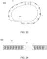
- FIG. 23illustrates a laser cut layout for a tricuspid ring, in accordance with at least one embodiment of the present disclosure.
- FIG. 24illustrates a 3D shape for a tricuspid ring, in accordance with at least one embodiment of the present disclosure.
- the replacement valveWhen implanting a replacement valve (e.g., an aortic valve, mitral valve, tricuspid valve, or other valve), the replacement valve can include a prosthesis attachment.
- the prosthesiscan be configured to secure the replacement valve in a patient's heart.
- An example of such a prosthesisis the AMENDTM Mitral Valve Repair Annuloplasty ring developed by Valcare Medical.
- the AMENDTM ringis a D-shaped ring configured to emulate the total valve replacement for patients who suffer from Mitral Regurgitation (MR, as described above). Additional detail related to prosthetic valves for mitral or tricuspid valve replacement can be found in U.S.
- a prosthetic ringcan be configured to include various anchor zones on a posterior side.
- the anchor zonesare positioned to emit anchors in different directions and/or angles from two or more windows on the cross section of the ring. For example, a portion of the anchors may be emitted to the ventricular side of the annulus tissue, and a portion of the anchors may be emitted to the atrial side of the annulus tissue.
- Such an arrangementcan provide for improved anchoring of the ring into the annulus tissue as compared to conventional mitral valve rings.
- FIGS. 1 - 4illustrate various views of an improved mitral valve ring 100 .
- the ring 100can include posterior side anchor zones that are configured to emit anchors in different directions and/or angles from two or more windows on the cross section of the ring.
- a portion of the anchorsare configured to be emitted to the ventricular side of a patient's annulus tissue, while a second portion of the anchors are configured to be emitted to the atrial side of the annulus tissue.
- two or more anchorscan be emitted from one window in different directions.
- FIG. 1illustrates a top view of the ring assembly 100 .
- the ring assembly 100can include an outer tube 102 that defines the shape of the ring assembly.
- the outer tube 102can include one or more windows about its circumference as well as one or more windows in its cross-section.
- One or more anchorscan be positioned and configured to extend through these windows.
- the ring assembly 100can also include a set of posterior zone anchors 110 . As shown in FIG. 1 , the posterior zone anchors 110 are generally positioned on the posterior of the ring assembly 100 .
- the ring assembly 100can further include anterior zone anchors 120 generally positioned on the anterior of the ring assembly.
- Each anchor zone(including both posterior zone anchors 110 and anterior zone anchors 120 ) can include atrial side anchors 111 as well as ventricular side anchors 112 (not shown in FIG. 1 but illustrated in, for example, FIG. 2 ).
- the atrial side anchors 111can be configured to be emitted into the atrial side of the patient's annulus tissue and the ventricular side anchors can be configured to be emitted into the ventricular side of the patient's annulus tissue.
- the ring assembly 100can include a closure device 150 .
- the closure device 150can be configured to lock a distal end of the ring assembly 100 to a proximal end of the ring assembly.
- the closure device 150can also be designed and configured to removably attach to a delivery system for the valve replacement implant.
- the closure device 150can include a pivot pin 153 that is configured to removably attach the ring assembly 100 to a delivery device as well as provide for rotation of the ring assembly when emitted from the delivery device.
- the pivot pin 153can be configured to provide for 90 degrees of rotation of the ring assembly 100 .
- the pivot pincan be configured to provide for additional ranges of rotation such as 75-105 degrees of rotation, 60-120 degrees of rotation, and other similar ranges of rotation.
- the ring assembly 100can further include a set of pins 103 .
- the pins 103can be positioned and configured to connect the outer tube 102 to the closure device 150 .
- the pins 103can be further positioned and configured to provide for routing of sutures as well as to function as a pulley while providing for rotation of a suture (e.g., 90 degree rotation) with minimal friction.
- FIG. 2illustrates a first side view of the ring assembly 100 , shown from the posterior and further illustrating the closure device 150 .
- FIG. 2further illustrates the alternative emitting direction of the atrial side anchors 111 in an outward and upward direction relative to a plane of the ring assembly 100 and the ventricular side anchors 112 in an outward and downward direction relative to the plane of the ring assembly 100 .
- FIG. 3illustrates a bottom view of the ring assembly 100 .
- FIG. 3illustrates the ventricular side anchors 112 .
- FIG. 3further illustrates additional anterior side anchors 120 that were obscured from view in FIG. 1 .
- various anchorscan be configured such that portions of the anchors can cross one another in different directions, thereby creating a closed loop and stapling effect of the tissue.
- anchors 121 and 122 as shown in FIG. 3are configured to cross one another in different directions, thereby having a stapling effect on the adjacent tissue, securely locking the ring assembly 100 into position.
- FIG. 4illustrates a second side view of the ring assembly 100 , shown further illustrating the crossing anchors 121 and 122 .
- the raw materials of the ring assembly 100 and various components included thereincan be selected from various materials, such as various polymers, shape memory materials such as Nitinol, metals such as stainless steel, or other similar materials safe for implanting; into or adjacent to living tissue.
- the ring assembly 100can include a combination of two or more different materials, such as stainless steel 316/316L and Nitinol. This combination is provided by way of example only, and other materials can be used alternately or additionally.
- the outer tube 102can be manufactured such that multiple windows are defined.
- the windowscan be positioned to facilitate deployment of the various anchors as described above.
- FIG. 5illustrates an example cut pattern 200 for creating the outer tube 102 as described above.
- the pattern 200shows an example cut pattern of a ring tube 202 with several windows 204 A, 204 B, 204 C and 204 D that allow deployment of anchors in different directions.
- anchorscan be emitted in the atrial side from windows 204 D, and anchors can be emitted from the ventricular side from windows 204 C.
- more than one anchorcan be emitted from one window with one or more anchors in the atrial side and one or more anchors in ventricular side.
- one or more anchorscan be emitted from different windows in the same direction.
- two windowse.g., 204 A and 204 B
- two windowscan be configured to provide for simultaneous deployment of anchors towards the ventricular side.
- FIGS. 6 and 7illustrate example cut patterns (e.g., laser cut patterns) for the anterior and/or posterior zone anchors such as posterior zone anchors 110 and anterior zone anchors 120 as described above. Additionally, as noted above, anchors can be emitted in both the atrial and ventricle directions, such as atrial anchors 111 and ventricle anchors 112 as described above.
- cut patternse.g., laser cut patterns
- cut pattern 300 as shown in FIGS. 6 and 7can be used to create one or more anchor zones 302 .
- the cut patterncan define a set of atrial anchors 304 and a set of ventricle anchors 306 within the anchor zone 302 .
- the cut pattern 300can also define an anchor stop feature 308 .
- the anchor stop feature 308can be configured to lock the anchor zone 302 into, for example, the outer tube of a ring assembly to prevent unintentional movement of the anchor zone.
- the anchor stop feature 308can be a passive feature that is activated as a result of a force exerted on the anchor zone 302 (e.g., a pulling force) causing a bending or other change to the geometry of the anchor stop feature 308 .
- the anchor stop feature 308can include an associated activation mechanism that facilitates activation of the anchor stop feature.
- the activation mechanismcan be an activation pulley that prevents the anchor stop feature 308 from bending of otherwise deforming such that a portion of the anchor stop feature exits through a corresponding hole on the outer tube of the ring assembly. Such an arrangement can lock the anchor zone 302 into position as the anchor stop feature 308 prevents any relative movement.
- pulling on the activator mechanism and removing it from the designated locationallows the anchor stop feature 308 to bend and allows relative movement of the anchor zone 302 in relation to the outer tube of the ring assembly.
- the anchor stop feature 308can be located in either the ventricular side or atrial side of the anchor zone 320 and/or outer tube. Additionally, in various embodiments, the anchor stop feature 308 can be positioned in any location along the anchor zone 302 . The position as shown in FIGS. 6 and 7 is shown by way of example only.
- laser cutting the ring assemblies as described hereinis provided by way of example only, and additional manufacturing techniques can be used.
- a stamping processcan be used to stamp the cut patterns as described above.
- FIGS. 8 and 9illustrate the cut patterns 300 as described above in regard to FIGS. 6 and 7 that have been, for example, heat treated and to include various bends and curves, thereby defining a specific three-dimensional shape for the anchor zones 302 .
- the anchor zones 302can be heat-treated and bent at an angle selected from a range of angles.
- the range of anglescan be from zero degrees (e.g., no additional bending) to 135 degrees.
- the ventricle anchors 306can be heat-treated to 45 degrees
- the atrial anchors 304can be heat-treated to 60 degrees.
- the anchor zonecan have a 3D shape that fits the zone location in the final ring assembly.
- the posterior anchor zonescan be curved to fit the posterior curvature of the ring assembly
- the anterior anchor zonescan be curved to fit the anterior curvature of the ring assembly.
- heat-treated bending and curvingis provided by way of example only. Depending upon the type of material being used and the design of the individual components such as the anchor zones, alternative bending and curving techniques can be used to form the anchor zones to the geometry of the final ring assembly.
- FIGS. 10 - 12illustrate detailed views of a closing mechanism 400 for a ring assembly, such as closing mechanism 150 as described above in regard to ring assembly 100 .
- a closing mechanismcan include a female component configured to lock to a male component.
- FIGS. 10 - 12illustrate various views and embodiments of the female component 402 .
- the female component 402can include a locking mechanism for releasably attaching to a male component or cup 404 .
- the female component 402can further include an unsnapping pin 406 .
- the unsnapping pincan be positioned and configured to unsnap or otherwise disconnect the female component 402 from the cup 404 of the ring assembly.
- the female component 402can include a pivot pin 408 for attaching the female component to an outer tube of the ring assembly.
- the pivot pin 408can be configured to function as an interface between the ring assembly and a delivery system, similar to pins 103 as described above.
- FIG. 11illustrates a cross-section of the female component 402 .
- the female component 402can include a disk 410 .
- the disk 410can be positioned to abut an end of the cup 404 when inserted into the female component 402 to provide for locking of the male component to the female component.
- the disk 410can be held in position with a cover.
- FIG. 12illustrates a view of the locking mechanism 400 with a portion of the cup 404 removed, showing additional detail of the unsnapping pin 406 .
- the unsnapping pin 406can be designed with two individual fingers extending from a central point such that, upon exerting a force (e.g., a squeezing force) upon an end of the fingers opposite the central point, the fingers deflect about the point.
- a forcee.g., a squeezing force
- the disk 410 and the unsnapping pin 406can be made from a shape memory alloy such as Nitinol.
- the other components of the female componentcan be made from various metallic materials such as stainless steel, aluminum, Nitinol, and titanium.
- the cup 404 and the female component 402are attached together with the unsnapping pin 406 . If properly inserted and positioned, the unsnapping pin 406 can visually verify that the two parts are well-attached and cannot open unintentionally. Conversely, upon activation of the unsnapping pin 406 by pulling it in a specific direction, it allows separation of the two components. By doing this, the ring close structure is compromised and the closed shape becomes open and allows retrieval of the implant into the delivery system.
- the female component 402can have one or more gold markers 412 that provide for confirmation of locking of the cup 404 and the female component during a clinical procedure.
- FIGS. 13 - 15illustrate various views of a ring assembly 500 .
- the ring assembly 500can include an outer tube, a set of posterior zone anchors, a set of anterior zone anchors, and a closure device 150 .
- the ring assembly 500 as shown in FIGS. 13 - 15can further include additional anchors 502 and 504 positioned adjacent to the closure device and configured to improve attachment of the ring assembly 500 to the patient's posterior annulus tissue.
- the anchors 502 and 504can be configured to be emitted in different directions and/or angles from one or more windows on the cross section of the outer tube in the area of the closure device.
- one or more additional anchorscan be configured to be emitted to the ventricular side of the annulus tissue, and one or more of the additional anchors can be configured to be emitted to the atrial side of the annulus tissue.
- two or more additional anchorscan be configured to be emitted from one window in the outer tube in different directions to each other.
- the anchorscan include additional features such as hooks, barbs, or other similar features for increasing durability and preventing detachment.
- a ring assemblycan further include bumps or other similar protrusions in the trigones area of the ring assembly.
- a ring assembly 600(shown without anchors in FIG. 16 and with anchors in FIG. 17 ) can include bumps 602 and 604 positioned on the portion of the ring assembly that will be adjacent to the fibrous trigones region of a patient's heart.
- the bumps 602 and 604or other similar protrusions or added features, can provide for added contact between the ring assembly 600 and the patient's trigones region of the annulus tissue.
- achieving such contactcan provide for better contact between the ring assembly 600 and the annulus tissue as compared to a ring assembly without the bumps in the trigones region. Similar to the ring assemblies as described above, various patterns and directions of anchors can be used to improve anchoring the ring assembly 600 to the annulus tissue as well.
- additional anchorscan be beneficial for providing additional anchoring points for a ring assembly.
- a single anchor or set of additional anchorscan be emitted from an existing window in an outer tube of a ring assembly providing a more robust anchoring point as compared to the curved anchors as described above.
- ring assembly 700can include additional anchors configured to provide a more robust anchoring point.
- an additional anchor 702can be emitted from a window for providing an additional anchoring point on the atrial side of the ring assembly 700 .
- FIG. 19illustrates an additional anchor 704 being emitted from a similar window for providing an additional anchoring point on the ventricular side of the ring assembly 700 .
- FIG. 20illustrates a set of two or more additional anchors emitting from a single window.
- additional anchors 702 and 704provide additional anchoring into the atrial side and the ventricular side of the ring assembly 700 respectively.
- resizing the ring assemblycan be desirable as a single ring assembly can accommodate an additional range of patients and valve sizes.
- a ring assemblycan include a flexible connection that is laser cut from a similar material as the outer tube of the ring assembly.
- the flexible connectioncan be configured to contract and/or expand to allow for changing the size of the ring before, during, and/or after implantation of the ring assembly.
- the ring assemblycan be manufactured from separate segments or components that are configured to be attached together with a mechanism or device that controls expansion and/or contraction of each side of a ring assembly separately or simultaneously.
- FIG. 21illustrates a ring assembly 800 that is configured to be resizable as described above.
- the ring assembly 800can include an anterior portion 802 and a posterior portion 804 .
- the anterior portion 802 and the posterior portion 804can be connected together with a set of adjustable components 806 and 808 .
- the adjustable components 806 and 808can be made from a flexible material configured to expand and/or contract, thereby changing the overall size of the ring assembly 800 .
- the anterior portion 802 and/or the posterior portion 804can include an adjustment mechanism that is configured to interact with the adjustable components 806 and 808 to change the size, shape and/or geometry of the ring assembly 800 .
- the adjustment mechanismscan include a ratcheting feature that is configured to interact with the adjustable components 806 and 808 to change the size of the ring assembly 800 .
- a ratcheting featureis provided by way of example only. Additional adjustment mechanisms such as friction-based holding devices, snap-based devices, winding devices, and other similar adjustment devices can be used. Additionally, it should be noted that two adjustable components 806 and 808 are shown by way of example. In additional implementations, various numbers of adjustable components can be used. For example, a single adjustable component can be included on one side of the ring assembly.
- FIG. 22illustrates a ring assembly 810 that is configured to be resizable, similar to ring assembly 800 as described above.
- the ring assembly 810can include an anterior portion 812 and two posterior portions 814 and 815 . Such an arrangement can provide for additional flexibility and sizing options when implanting the ring assembly 810 .
- the anterior portion 812can be connected to the posterior portion 815 with a first adjustable component 816 .
- the anterior portioncan be connected to the posterior portion 814 with a second adjustable component 818 .
- the posterior portions 814 and 815can be configured to releasably attach to one another via a closure device such as closure device 150 as described above.
- ring assemblies as described abovecan be designed and shaped for various functions such as mitral valve replacement.
- a similar ring assemblycan be designed and constructed for tricuspid valve replacement as well.
- a tricuspid ringcan be designed with additional features such as a release zone positioned on the ring assembly at a location that will be adjacent to a patient's atrioventricular node or valves.
- FIGS. 23 and 24illustrate an example tricuspid ring assembly 900 ( FIG. 23 illustrating a 3D view of the assembly, while FIG. 24 illustrates a flat cut pattern view).
- the outer tube 902 of the ring assembly 900can include multiple windows through which anchors can be emitted as described above.
- the ring assembly 900can further include a release zone 904 configured and positioned at a location that will be adjacent to a patient's atrioventricular node or valves when the ring assembly is implanted.
- the release zone 904does not have any anchors. Rather, the alternate shape and profile of the release zone provides for interference between the ring assembly 900 and the patient's atrioventricular node or valves, thereby securing the ring assembly in position.
- compositions, methods, and devicesare described in terms of “comprising” various components or steps (interpreted as meaning “including, but not limited to”), the compositions, methods, and devices can also “consist essentially of” or “consist of” the various components and steps, and such terminology should be interpreted as defining essentially closed-member groups. It will be further understood by those within the art that if a specific number of an introduced claim recitation is intended, such an intent will be explicitly recited in the claim, and in the absence of such recitation no such intent is present.
- a rangeincludes each individual member.
- a group having 1-3 cellsrefers to groups having 1, 2, or 3 cells.
- a group having 1-5 cellsrefers to groups having 1, 2, 3, 4, or 5 cells, and so forth.
Landscapes
- Health & Medical Sciences (AREA)
- Cardiology (AREA)
- Life Sciences & Earth Sciences (AREA)
- General Health & Medical Sciences (AREA)
- Public Health (AREA)
- Biomedical Technology (AREA)
- Heart & Thoracic Surgery (AREA)
- Engineering & Computer Science (AREA)
- Veterinary Medicine (AREA)
- Animal Behavior & Ethology (AREA)
- Vascular Medicine (AREA)
- Oral & Maxillofacial Surgery (AREA)
- Transplantation (AREA)
- Surgery (AREA)
- Molecular Biology (AREA)
- Nuclear Medicine, Radiotherapy & Molecular Imaging (AREA)
- Medical Informatics (AREA)
- Rheumatology (AREA)
- Prostheses (AREA)
- Surgical Instruments (AREA)
Abstract
Description
Claims (6)
Priority Applications (3)
| Application Number | Priority Date | Filing Date | Title |
|---|---|---|---|
| US15/923,677US11576779B2 (en) | 2017-03-17 | 2018-03-16 | Mitral or tricuspid repair systems with multi-directional anchors |
| US18/156,795US12279955B2 (en) | 2017-03-17 | 2023-01-19 | Mitral or tricuspid repair systems with multi-directional anchors |
| US19/174,702US20250235316A1 (en) | 2017-03-17 | 2025-04-09 | Mitral or tricuspid repair systems with multi-directional anchors |
Applications Claiming Priority (2)
| Application Number | Priority Date | Filing Date | Title |
|---|---|---|---|
| US201762472633P | 2017-03-17 | 2017-03-17 | |
| US15/923,677US11576779B2 (en) | 2017-03-17 | 2018-03-16 | Mitral or tricuspid repair systems with multi-directional anchors |
Related Child Applications (1)
| Application Number | Title | Priority Date | Filing Date |
|---|---|---|---|
| US18/156,795ContinuationUS12279955B2 (en) | 2017-03-17 | 2023-01-19 | Mitral or tricuspid repair systems with multi-directional anchors |
Publications (2)
| Publication Number | Publication Date |
|---|---|
| US20190091022A1 US20190091022A1 (en) | 2019-03-28 |
| US11576779B2true US11576779B2 (en) | 2023-02-14 |
Family
ID=63522706
Family Applications (3)
| Application Number | Title | Priority Date | Filing Date |
|---|---|---|---|
| US15/923,677Active2038-09-03US11576779B2 (en) | 2017-03-17 | 2018-03-16 | Mitral or tricuspid repair systems with multi-directional anchors |
| US18/156,795ActiveUS12279955B2 (en) | 2017-03-17 | 2023-01-19 | Mitral or tricuspid repair systems with multi-directional anchors |
| US19/174,702PendingUS20250235316A1 (en) | 2017-03-17 | 2025-04-09 | Mitral or tricuspid repair systems with multi-directional anchors |
Family Applications After (2)
| Application Number | Title | Priority Date | Filing Date |
|---|---|---|---|
| US18/156,795ActiveUS12279955B2 (en) | 2017-03-17 | 2023-01-19 | Mitral or tricuspid repair systems with multi-directional anchors |
| US19/174,702PendingUS20250235316A1 (en) | 2017-03-17 | 2025-04-09 | Mitral or tricuspid repair systems with multi-directional anchors |
Country Status (5)
| Country | Link |
|---|---|
| US (3) | US11576779B2 (en) |
| EP (2) | EP4501386A3 (en) |
| CN (1) | CN108618871A (en) |
| IL (2) | IL305927B2 (en) |
| WO (1) | WO2018170424A1 (en) |
Cited By (4)
| Publication number | Priority date | Publication date | Assignee | Title |
|---|---|---|---|---|
| US12115069B2 (en) | 2012-02-29 | 2024-10-15 | Valcare Medical, Inc. | Percutaneous annuloplasty system with anterior-posterior adjustment |
| US12279955B2 (en) | 2017-03-17 | 2025-04-22 | Valcare Medical, Inc. | Mitral or tricuspid repair systems with multi-directional anchors |
| US12396853B2 (en) | 2019-06-11 | 2025-08-26 | Valcare Medical, Inc. | Systems and methods for delivery of chordae replacement system |
| US12409034B2 (en) | 2019-06-11 | 2025-09-09 | Valcare Medical, Inc. | Annuloplasty ring with posterior leaflet for minimally invasive treatment |
Families Citing this family (27)
| Publication number | Priority date | Publication date | Assignee | Title |
|---|---|---|---|---|
| US20200146854A1 (en) | 2016-05-16 | 2020-05-14 | Elixir Medical Corporation | Methods and devices for heart valve repair |
| WO2019195860A2 (en) | 2018-04-04 | 2019-10-10 | Vdyne, Llc | Devices and methods for anchoring transcatheter heart valve |
| US11278437B2 (en) | 2018-12-08 | 2022-03-22 | Vdyne, Inc. | Compression capable annular frames for side delivery of transcatheter heart valve replacement |
| US10321995B1 (en) | 2018-09-20 | 2019-06-18 | Vdyne, Llc | Orthogonally delivered transcatheter heart valve replacement |
| US11344413B2 (en) | 2018-09-20 | 2022-05-31 | Vdyne, Inc. | Transcatheter deliverable prosthetic heart valves and methods of delivery |
| US11071627B2 (en) | 2018-10-18 | 2021-07-27 | Vdyne, Inc. | Orthogonally delivered transcatheter heart valve frame for valve in valve prosthesis |
| US10595994B1 (en) | 2018-09-20 | 2020-03-24 | Vdyne, Llc | Side-delivered transcatheter heart valve replacement |
| US12186187B2 (en) | 2018-09-20 | 2025-01-07 | Vdyne, Inc. | Transcatheter deliverable prosthetic heart valves and methods of delivery |
| US11109969B2 (en) | 2018-10-22 | 2021-09-07 | Vdyne, Inc. | Guidewire delivery of transcatheter heart valve |
| US11534300B2 (en)* | 2018-12-03 | 2022-12-27 | Valcare, Inc. | Stabilizing and adjusting tool for controlling a minimally invasive mitral / tricuspid valve repair system |
| US10653522B1 (en) | 2018-12-20 | 2020-05-19 | Vdyne, Inc. | Proximal tab for side-delivered transcatheter heart valve prosthesis |
| US11253359B2 (en) | 2018-12-20 | 2022-02-22 | Vdyne, Inc. | Proximal tab for side-delivered transcatheter heart valves and methods of delivery |
| WO2020146842A1 (en) | 2019-01-10 | 2020-07-16 | Vdyne, Llc | Anchor hook for side-delivery transcatheter heart valve prosthesis |
| US11185409B2 (en) | 2019-01-26 | 2021-11-30 | Vdyne, Inc. | Collapsible inner flow control component for side-delivered transcatheter heart valve prosthesis |
| US11273032B2 (en) | 2019-01-26 | 2022-03-15 | Vdyne, Inc. | Collapsible inner flow control component for side-deliverable transcatheter heart valve prosthesis |
| WO2020181154A2 (en) | 2019-03-05 | 2020-09-10 | Vdyne, Inc. | Tricuspid regurgitation control devices for orthogonal transcatheter heart valve prosthesis |
| US11076956B2 (en) | 2019-03-14 | 2021-08-03 | Vdyne, Inc. | Proximal, distal, and anterior anchoring tabs for side-delivered transcatheter mitral valve prosthesis |
| US10758346B1 (en) | 2019-03-14 | 2020-09-01 | Vdyne, Inc. | A2 clip for side-delivered transcatheter mitral valve prosthesis |
| US10631983B1 (en) | 2019-03-14 | 2020-04-28 | Vdyne, Inc. | Distal subannular anchoring tab for side-delivered transcatheter valve prosthesis |
| US11173027B2 (en) | 2019-03-14 | 2021-11-16 | Vdyne, Inc. | Side-deliverable transcatheter prosthetic valves and methods for delivering and anchoring the same |
| CA3138875A1 (en) | 2019-05-04 | 2020-11-12 | Vdyne, Inc. | Cinch device and method for deployment of a side-delivered prosthetic heart valve in a native annulus |
| US11793628B2 (en) | 2019-07-15 | 2023-10-24 | Valcare, Inc. | Transcatheter bio-prosthesis member and support structure |
| EP4480458A3 (en) | 2019-08-20 | 2025-04-09 | Vdyne, Inc. | Delivery devices for side-deliverable transcatheter prosthetic valves |
| CN120531525A (en) | 2019-08-26 | 2025-08-26 | 维迪内股份有限公司 | Laterally deliverable transcatheter prosthetic valve and method for its delivery and anchoring |
| US11234813B2 (en) | 2020-01-17 | 2022-02-01 | Vdyne, Inc. | Ventricular stability elements for side-deliverable prosthetic heart valves and methods of delivery |
| CN212490265U (en)* | 2020-08-31 | 2021-02-09 | 宁波健世生物科技有限公司 | Anti-drop anchoring mechanism applied to implanted prosthesis |
| CN118924494A (en)* | 2023-10-20 | 2024-11-12 | 北京新尖科技有限公司 | Valve stent and valve prosthesis |
Citations (182)
| Publication number | Priority date | Publication date | Assignee | Title |
|---|---|---|---|---|
| US4602911A (en) | 1982-08-19 | 1986-07-29 | General Resorts S.A. | Adjustable ringprosthesis |
| WO1990009153A1 (en) | 1989-02-13 | 1990-08-23 | Baxter International Inc. | Selectively flexible annuloplasty ring |
| US5236440A (en) | 1992-04-14 | 1993-08-17 | American Cyanamid Company | Surgical fastener |
| US5306296A (en) | 1992-08-21 | 1994-04-26 | Medtronic, Inc. | Annuloplasty and suture rings |
| US5695518A (en) | 1990-12-28 | 1997-12-09 | Laerum; Frode | Filtering device for preventing embolism and/or distension of blood vessel walls |
| US5716370A (en) | 1996-02-23 | 1998-02-10 | Williamson, Iv; Warren | Means for replacing a heart valve in a minimally invasive manner |
| US5855614A (en) | 1993-02-22 | 1999-01-05 | Heartport, Inc. | Method and apparatus for thoracoscopic intracardiac procedures |
| US6113611A (en) | 1998-05-28 | 2000-09-05 | Advanced Vascular Technologies, Llc | Surgical fastener and delivery system |
| US6231602B1 (en) | 1999-04-16 | 2001-05-15 | Edwards Lifesciences Corporation | Aortic annuloplasty ring |
| US20020151970A1 (en) | 1999-02-10 | 2002-10-17 | Garrison Michi E. | Methods and devices for implanting cardiac valves |
| US20020151961A1 (en) | 2000-01-31 | 2002-10-17 | Lashinski Randall T. | Medical system and method for remodeling an extravascular tissue structure |
| US20020188170A1 (en) | 2001-04-27 | 2002-12-12 | Santamore William P. | Prevention of myocardial infarction induced ventricular expansion and remodeling |
| US20020198526A1 (en) | 2000-06-23 | 2002-12-26 | Shaolian Samuel M. | Formed in place fixation system with thermal acceleration |
| WO2003017874A1 (en) | 2001-08-24 | 2003-03-06 | Edwards Lifesciences Corporation | Self-molding annuloplasty ring |
| US20030050693A1 (en) | 2001-09-10 | 2003-03-13 | Quijano Rodolfo C. | Minimally invasive delivery system for annuloplasty rings |
| US20030078465A1 (en) | 2001-10-16 | 2003-04-24 | Suresh Pai | Systems for heart treatment |
| US20030078671A1 (en) | 2001-04-27 | 2003-04-24 | Lesniak Jeanne M. | Prevention of myocardial infarction induced ventricular expansion and remodeling |
| WO2003047467A1 (en) | 2001-12-04 | 2003-06-12 | Edwards Lifesciences Corporation | Minimally-invasive annuloplasty repair segment delivery template system |
| US6619291B2 (en) | 2001-04-24 | 2003-09-16 | Edwin J. Hlavka | Method and apparatus for catheter-based annuloplasty |
| US6629534B1 (en) | 1999-04-09 | 2003-10-07 | Evalve, Inc. | Methods and apparatus for cardiac valve repair |
| US20030191528A1 (en) | 2000-06-02 | 2003-10-09 | Quijano Rodolfo C. | Expandable medical implant and percutaneous delivery |
| US20030199974A1 (en) | 2002-04-18 | 2003-10-23 | Coalescent Surgical, Inc. | Annuloplasty apparatus and methods |
| US20030198605A1 (en) | 1998-02-13 | 2003-10-23 | Montgomery R. Eric | Light-activated tooth whitening composition and method of using same |
| US6669687B1 (en) | 1999-06-25 | 2003-12-30 | Vahid Saadat | Apparatus and methods for treating tissue |
| US6689048B2 (en) | 2000-01-14 | 2004-02-10 | Acorn Cardiovascular, Inc. | Delivery of cardiac constraint jacket |
| US20040044364A1 (en) | 2002-08-29 | 2004-03-04 | Devries Robert | Tissue fasteners and related deployment systems and methods |
| US20040068276A1 (en) | 2002-10-04 | 2004-04-08 | Steve Golden | Anastomosis apparatus and methods |
| US6726704B1 (en) | 1998-05-29 | 2004-04-27 | By-Pass, Inc. | Advanced closure device |
| US20040122514A1 (en) | 2002-12-20 | 2004-06-24 | Fogarty Thomas J. | Biologically implantable prosthesis and methods of using the same |
| US20040138744A1 (en) | 2000-01-31 | 2004-07-15 | Randall Lashinski | Transluminal mitral annuloplasty with active anchoring |
| US20040148021A1 (en) | 2002-08-29 | 2004-07-29 | Cartledge Richard G. | Implantable devices for controlling the internal circumference of an anatomic orifice or lumen |
| US6776784B2 (en) | 2001-09-06 | 2004-08-17 | Core Medical, Inc. | Clip apparatus for closing septal defects and methods of use |
| US6790229B1 (en) | 1999-05-25 | 2004-09-14 | Eric Berreklouw | Fixing device, in particular for fixing to vascular wall tissue |
| US6797002B2 (en) | 2000-02-02 | 2004-09-28 | Paul A. Spence | Heart valve repair apparatus and methods |
| US20040193191A1 (en) | 2003-02-06 | 2004-09-30 | Guided Delivery Systems, Inc. | Devices and methods for heart valve repair |
| KR20040095482A (en) | 2003-05-09 | 2004-11-15 | 안성순 | annuloplasty ring |
| US20040243230A1 (en) | 2003-05-20 | 2004-12-02 | The Cleveland Clinic Foundation | Apparatus and methods for repair of a cardiac valve |
| US20040249391A1 (en) | 2001-08-09 | 2004-12-09 | Christy Cummins | Surgical stapling device and method |
| US20040260393A1 (en) | 2000-09-20 | 2004-12-23 | Ample Medical, Inc. | Devices, systems, and methods for reshaping a heart valve annulus |
| US20040260394A1 (en) | 2003-06-20 | 2004-12-23 | Medtronic Vascular, Inc. | Cardiac valve annulus compressor system |
| US20050020696A1 (en) | 2000-04-21 | 2005-01-27 | Montgomery Robert Eric | Low peak exotherm curable compositions |
| US20050033325A1 (en) | 2001-02-16 | 2005-02-10 | Ethicon, Inc. | Surgical knot pusher and method of use |
| US20050065550A1 (en) | 2003-02-06 | 2005-03-24 | Guided Delivery Systems, Inc. | Delivery devices and methods for heart valve repair |
| US20050090846A1 (en) | 2003-07-18 | 2005-04-28 | Wesley Pedersen | Valvuloplasty devices and methods |
| US20050096740A1 (en) | 2001-01-30 | 2005-05-05 | Edwards Lifesciences Ag | Transluminal mitral annuloplasty |
| US6893459B1 (en) | 2000-09-20 | 2005-05-17 | Ample Medical, Inc. | Heart valve annulus device and method of using same |
| US20050113910A1 (en) | 2002-01-04 | 2005-05-26 | David Paniagua | Percutaneously implantable replacement heart valve device and method of making same |
| WO2005046488A2 (en) | 2003-11-12 | 2005-05-26 | Medtronic Vascular, Inc. | Cardiac valve annulus reduction system |
| US20050137695A1 (en) | 2003-12-23 | 2005-06-23 | Sadra Medical | Replacement valve and anchor |
| US20050137692A1 (en) | 2003-12-23 | 2005-06-23 | Haug Ulrich R. | Methods and apparatus for endovascularly replacing a patient's heart valve |
| US20050203549A1 (en) | 2004-03-09 | 2005-09-15 | Fidel Realyvasquez | Methods and apparatus for off pump aortic valve replacement with a valve prosthesis |
| US20050222678A1 (en) | 2004-04-05 | 2005-10-06 | Lashinski Randall T | Remotely adjustable coronary sinus implant |
| US20050240200A1 (en) | 2004-04-23 | 2005-10-27 | Bjarne Bergheim | Method and system for cardiac valve delivery |
| US20050267572A1 (en) | 2004-05-14 | 2005-12-01 | St. Jude Medical, Inc. | Systems and methods for holding annuloplasty rings |
| US20050283190A1 (en) | 2004-06-16 | 2005-12-22 | Huitema Thomas W | Surgical fastener |
| US20050288778A1 (en) | 2004-06-29 | 2005-12-29 | Emanuel Shaoulian | Selectively adjustable cardiac valve implants |
| US20060009737A1 (en) | 2004-07-12 | 2006-01-12 | Whiting James S | Methods and devices for transseptal access |
| US20060020327A1 (en) | 2004-05-05 | 2006-01-26 | Lashinski Randall T | Nonstented heart valves with formed in situ support |
| US20060122633A1 (en)* | 2002-06-13 | 2006-06-08 | John To | Methods and devices for termination |
| US20060129025A1 (en) | 2002-06-27 | 2006-06-15 | Levine Robert A | Systems for and methods of atrioventricular valve regurgitation and reversing ventricular remodeling |
| US20060161169A1 (en) | 2003-05-02 | 2006-07-20 | Cardiac Dimensions, Inc., A Delaware Corporation | Device and method for modifying the shape of a body organ |
| US20060184242A1 (en) | 2003-10-20 | 2006-08-17 | Samuel Lichtenstein | Method and apparatus for percutaneous reduction of anterior-posterior diameter of mitral valve |
| US20060184240A1 (en) | 2003-06-25 | 2006-08-17 | Georgia Tech Research Corporation | Annuloplasty chain |
| US20060195134A1 (en) | 2005-02-28 | 2006-08-31 | Medtronic Vascular, Inc. | Device, system, and method for aiding valve annuloplasty |
| US20060195183A1 (en) | 2005-02-18 | 2006-08-31 | The Cleveland Clinic Foundation | Apparatus and methods for replacing a cardiac valve |
| US7101395B2 (en) | 2002-06-12 | 2006-09-05 | Mitral Interventions, Inc. | Method and apparatus for tissue connection |
| US7114953B1 (en) | 2003-04-25 | 2006-10-03 | Wagner Eugene C | Tooth whitening appliance having membrane covered applicator |
| US20060241748A1 (en) | 2005-03-25 | 2006-10-26 | Lee Leonard Y | Methods and apparatus for controlling the internal circumference of an anatomic orifice or lumen |
| US20060282161A1 (en) | 2003-06-20 | 2006-12-14 | Medtronic Vascular, Inc. | Valve annulus reduction system |
| US20070016287A1 (en) | 2005-03-25 | 2007-01-18 | Cartledge Richard G | Methods and apparatus for controlling the internal circumference of an anatomic orifice or lumen |
| US20070027533A1 (en) | 2005-07-28 | 2007-02-01 | Medtronic Vascular, Inc. | Cardiac valve annulus restraining device |
| US20070038296A1 (en) | 2005-07-15 | 2007-02-15 | Cleveland Clinic | Apparatus and method for remodeling a cardiac valve annulus |
| US20070067027A1 (en) | 2005-09-14 | 2007-03-22 | Micardia Corporation | Left atrial balloon catheter |
| US20070073098A1 (en) | 2005-09-23 | 2007-03-29 | Ellipse Technologies, Inc. | Method and apparatus for adjusting body lumens |
| US20070080188A1 (en) | 2003-12-23 | 2007-04-12 | Mitralign, Inc. | Tissue fastening systems and methods |
| US20070093854A1 (en) | 2002-04-17 | 2007-04-26 | Tyco Healthcare Group Lp | Tacking tool and tack |
| US20070118215A1 (en) | 2005-11-16 | 2007-05-24 | Micardia Corporation | Magnetic engagement of catheter to implantable device |
| US20070128132A1 (en) | 2005-11-09 | 2007-06-07 | Remigio Piergallini | Teeth whitening composition and methods |
| US20070135913A1 (en) | 2004-06-29 | 2007-06-14 | Micardia Corporation | Adjustable annuloplasty ring activation system |
| US20070142907A1 (en) | 2005-12-16 | 2007-06-21 | Micardia Corporation | Adjustable prosthetic valve implant |
| US7238191B2 (en) | 2002-09-04 | 2007-07-03 | Endoart S.A. | Surgical ring featuring a reversible diameter remote control system |
| US20070213812A1 (en) | 2002-11-15 | 2007-09-13 | Webler William E | Apparatuses and methods for delivering/deploying a medical device in a vessel |
| US20070233239A1 (en) | 2005-07-15 | 2007-10-04 | The Cleveland Clinic Foundation | Apparatus and method for reducing cardiac valve regurgitation |
| US20070244553A1 (en) | 2006-04-12 | 2007-10-18 | Medtronic Vascular, Inc. | Annuloplasty Device Having a Helical Anchor and Methods for its Use |
| US20070244555A1 (en) | 2006-04-12 | 2007-10-18 | Medtronic Vascular, Inc. | Annuloplasty Device Having a Helical Anchor and Methods for its Use |
| US7285087B2 (en) | 2004-07-15 | 2007-10-23 | Micardia Corporation | Shape memory devices and methods for reshaping heart anatomy |
| US20070250161A1 (en) | 2006-04-25 | 2007-10-25 | Medtronic Vascular, Inc. | Cardiac valve annulus restraining device |
| US20070293942A1 (en) | 2006-06-16 | 2007-12-20 | Daryush Mirzaee | Prosthetic valve and deployment method |
| US20080177381A1 (en) | 2007-01-19 | 2008-07-24 | The Cleveland Clinic Foundation | Method for implanting a cardiovascular valve |
| US20080177380A1 (en) | 2007-01-19 | 2008-07-24 | Starksen Niel F | Methods and devices for heart tissue repair |
| US20080200980A1 (en) | 2006-10-19 | 2008-08-21 | Kevin Robin | Profile reduction of valve implant |
| US20080243220A1 (en) | 2007-03-28 | 2008-10-02 | Advanced Bionics Corporation | Lead anchor for implantable stimulation devices |
| US20080262609A1 (en) | 2006-12-05 | 2008-10-23 | Valtech Cardio, Ltd. | Segmented ring placement |
| US20080262513A1 (en) | 2007-02-15 | 2008-10-23 | Hansen Medical, Inc. | Instrument driver having independently rotatable carriages |
| US20080306586A1 (en) | 2007-02-05 | 2008-12-11 | Cartledge Richard G | Minimally Invasive System for Delivering and Securing an Annular Implant |
| US20090088838A1 (en) | 2006-05-12 | 2009-04-02 | Shaolian Samuel M | Adjustable annuloplasty ring and activation system |
| WO2009052427A1 (en) | 2007-10-19 | 2009-04-23 | Guided Delivery Systems Inc. | Systems and methods for cardiac remodeling |
| US20090118747A1 (en) | 2007-11-05 | 2009-05-07 | Tyco Healthcare Group Lp | Novel surgical fastener |
| US20090125098A1 (en) | 2007-11-09 | 2009-05-14 | Cook Incorporated | Aortic valve stent graft |
| US20090149872A1 (en) | 2005-03-17 | 2009-06-11 | Amir Gross | Mitral valve treatment techniques |
| US7569072B2 (en) | 1999-04-23 | 2009-08-04 | St. Jude Medical Atg, Inc. | Artificial heart valve attachment apparatus and methods |
| US20090216322A1 (en) | 2007-08-10 | 2009-08-27 | Le Le | Adjustable annuloplasty ring and activation system |
| US20090222083A1 (en) | 2008-02-06 | 2009-09-03 | Guided Delivery Systems Inc. | Multi-window guide tunnel |
| US20090238778A1 (en) | 2008-03-19 | 2009-09-24 | Mordas Carolyn J | Tooth whitening compositions, delivery systems and methods |
| WO2009120764A2 (en) | 2008-03-25 | 2009-10-01 | Ellipse Technologies, Inc. | Systems and methods for adjusting an annuloplasty ring with an integrated magnetic drive |
| US20090299470A1 (en) | 2008-05-09 | 2009-12-03 | Edwards Lifesciences Corporation | Quick-Release Annuloplasty Ring Holder |
| US7635329B2 (en) | 2004-09-27 | 2009-12-22 | Evalve, Inc. | Methods and devices for tissue grasping and assessment |
| US20100010616A1 (en) | 2003-10-08 | 2010-01-14 | Arbor Surgical Technologies, Inc. | Attachment device and methods of using the same |
| WO2010004546A1 (en) | 2008-06-16 | 2010-01-14 | Valtech Cardio, Ltd. | Annuloplasty devices and methods of delivery therefor |
| US20100030014A1 (en) | 2008-07-30 | 2010-02-04 | Cube S.R.L. | Intracardiac device for restoring the functional elasticity of the cardiac structures, holding tool for the intracardiac device, and method for implantation of the intracardiac device in the heart |
| US20100063586A1 (en) | 2006-05-15 | 2010-03-11 | John Michael Hasenkam | System and a method for altering the geometry of the heart |
| US20100121433A1 (en) | 2007-01-08 | 2010-05-13 | Millipede Llc, A Corporation Of Michigan | Reconfiguring heart features |
| US7717954B2 (en) | 1999-06-29 | 2010-05-18 | Edwards Lifesciences Ag | Device and method for treatment of mitral insufficiency |
| US20100161047A1 (en) | 2008-12-22 | 2010-06-24 | Valtech Cardio, Ltd. | Adjustable partial annuloplasty ring and mechanism therefor |
| WO2010085659A1 (en) | 2009-01-22 | 2010-07-29 | St. Jude Medical | Magnetic docking system and method for the long term adjustment of an implantable device |
| US20100211166A1 (en) | 2009-02-17 | 2010-08-19 | Eran Miller | Actively-engageable movement-restriction mechanism for use with an annuloplasty structure |
| US20100249920A1 (en) | 2007-01-08 | 2010-09-30 | Millipede Llc | Reconfiguring heart features |
| US20100266989A1 (en) | 2006-11-09 | 2010-10-21 | Klox Technologies Inc. | Teeth whitening compositions and methods |
| US20100280605A1 (en) | 2009-05-04 | 2010-11-04 | Valtech Cardio, Ltd. | Deployment techniques for annuloplasty ring |
| US20100286767A1 (en) | 2009-05-07 | 2010-11-11 | Valtech Cardio, Ltd. | Annuloplasty ring with intra-ring anchoring |
| US7837729B2 (en) | 2002-12-05 | 2010-11-23 | Cardiac Dimensions, Inc. | Percutaneous mitral valve annuloplasty delivery system |
| WO2011011443A2 (en) | 2009-07-20 | 2011-01-27 | Micardia Corporation | Adjustable annuloplasty ring with subcutaneous activation port |
| US20110022168A1 (en) | 2009-01-22 | 2011-01-27 | Cartledge Richard G | Post-operative adjustment tool, minimally invasive attachment apparatus, and adjustable tricuspid ring |
| US20110027753A1 (en) | 2009-07-30 | 2011-02-03 | Maurat Vincent | Application tip |
| US20110034953A1 (en) | 2008-04-21 | 2011-02-10 | Simcha Milo | Surgical stapling systems |
| US20110066231A1 (en) | 2007-01-03 | 2011-03-17 | Cartledge Richard G | Implantable devices for controlling the size and shape of an anatomical structure or lumen |
| US20110093062A1 (en) | 2009-02-09 | 2011-04-21 | St. Jude Medical | Inflatable minimally invasive system for delivering and securing an annular implant |
| US20110106247A1 (en) | 2009-10-29 | 2011-05-05 | Valtech Cardio, Ltd. | Tissue anchor for annuloplasty device |
| US20110106245A1 (en) | 2009-10-29 | 2011-05-05 | Valtech Cardio, Ltd. | Apparatus for guide-wire based advancement of a rotation assembly |
| US20110137397A1 (en) | 2009-12-04 | 2011-06-09 | Edwards Lifesciences Corporation | Prosthetic valve for replacing mitral valve |
| US20110190879A1 (en) | 2010-02-03 | 2011-08-04 | Edwards Lifesciences Corporation | Devices and Methods for Treating a Heart |
| US20110208298A1 (en) | 2010-02-24 | 2011-08-25 | Medtronic Ventor Technologies Ltd | Mitral Prosthesis and Methods for Implantation |
| US20110224785A1 (en) | 2010-03-10 | 2011-09-15 | Hacohen Gil | Prosthetic mitral valve with tissue anchors |
| US20110257728A1 (en) | 2010-04-15 | 2011-10-20 | Medtronic, Inc. | Catheter-Based Annuloplasty System and Method |
| US20110282361A1 (en) | 2009-12-02 | 2011-11-17 | Eran Miller | Delivery tool for implantation of spool assembly coupled to a helical anchor |
| US20110301699A1 (en) | 1999-06-25 | 2011-12-08 | Hansen Medical, Inc. | Apparatus and methods for treating tissue |
| WO2012004679A2 (en) | 2010-07-09 | 2012-01-12 | Highlife Sas | Transcatheter atrio-ventricular valve prosthesis |
| US20120022557A1 (en) | 2010-07-26 | 2012-01-26 | Valtech Cardio, Ltd. | Multiple anchor delivery tool |
| US20120022644A1 (en) | 2008-12-22 | 2012-01-26 | Valtech Cardio, Ltd. | Partially-adjustable annuloplasty structure |
| WO2012019052A2 (en) | 2010-08-04 | 2012-02-09 | Micardia Corporation | Percutaneous transcatheter repair of heart valves |
| US20120059458A1 (en) | 2010-09-01 | 2012-03-08 | Maurice Buchbinder | Cardiac Valve Support Structure |
| US20120095455A1 (en) | 2000-02-11 | 2012-04-19 | The General Hospital Corporation | Photochemical tissue bonding |
| US8163014B2 (en) | 2005-02-28 | 2012-04-24 | Medtronic, Inc. | Conformable prostheses for implanting two-piece heart valves and methods for using them |
| WO2012063228A1 (en) | 2010-11-12 | 2012-05-18 | Ht Consultant Di Giovanni Righini | Prosthesis for cardiovascular valve |
| US8182529B2 (en) | 2002-12-05 | 2012-05-22 | Cardiac Dimensions, Inc. | Percutaneous mitral valve annuloplasty device delivery method |
| US20120136436A1 (en) | 2008-12-22 | 2012-05-31 | Valtech Cardio, Ltd. | Adjustable annuloplasty devices and adjustment mechanisms therefor |
| US20120165930A1 (en) | 2010-12-23 | 2012-06-28 | The Foundy, Llc | System for mitral valve repair and replacement |
| WO2012095159A2 (en) | 2011-01-11 | 2012-07-19 | Hans Reiner Figulla | Prosthetic valve for replacing an atrioventricular heart valve |
| US8236049B2 (en) | 2008-06-20 | 2012-08-07 | Edwards Lifesciences Corporation | Multipiece prosthetic mitral valve and method |
| WO2012106354A1 (en) | 2011-01-31 | 2012-08-09 | St. Jude Medical, Inc. | Adjustable prosthetic anatomical device holder and handle for the implantation of an annuloplasty ring |
| US20120245604A1 (en) | 2011-03-25 | 2012-09-27 | Kardium Inc. | Medical kit for constricting tissue or a bodily orifice, for example, a mitral valve |
| US8287591B2 (en) | 2008-09-19 | 2012-10-16 | Edwards Lifesciences Corporation | Transformable annuloplasty ring configured to receive a percutaneous prosthetic heart valve implantation |
| US20120310330A1 (en) | 2011-06-01 | 2012-12-06 | Micardia Corporation | Percutaneous transcatheter repair of heart valves via trans-apical access |
| RU125062U1 (en) | 2011-08-30 | 2013-02-27 | Закрытое Акционерное Общество Научно-Производственное Предприятие "Мединж" | FLEXIBLE PROTESIS OF THE VALVE OF THE HEART |
| US20130087598A1 (en) | 2005-06-10 | 2013-04-11 | Cook Medical Technologies Llc | Medical Stapler |
| US20130116780A1 (en) | 2011-11-04 | 2013-05-09 | Valtech Cardio, Ltd. | Implant having multiple rotational assemblies |
| WO2013095816A1 (en) | 2011-12-21 | 2013-06-27 | Edwards Lifesciences Corporation | Anchoring device and method for replacing or repairing a heart valve |
| US20130204361A1 (en) | 2010-02-03 | 2013-08-08 | Medtronic ATS Medical, Inc. | Semi-flexible annuloplasty ring |
| US20130226290A1 (en) | 2012-02-29 | 2013-08-29 | ValCare,Inc. | Methods, devices, and systems for percutaneously anchoring annuloplasty rings |
| US20130226289A1 (en) | 2012-02-29 | 2013-08-29 | Valcare, Inc. | Percutaneous annuloplasty system with anterior-posterior adjustment |
| WO2013128436A1 (en) | 2012-02-28 | 2013-09-06 | Mvalve Technologies Ltd. | Single-ring cardiac valve support |
| US20130282114A1 (en) | 2012-04-19 | 2013-10-24 | Caisson Interventional, LLC | Heart valve assembly systems and methods |
| US20130289720A1 (en) | 2012-04-27 | 2013-10-31 | Nikola Dobrilovic | Prosthetic device for heart valve reinforcement and remodeling procedures |
| US8579968B1 (en) | 2010-05-19 | 2013-11-12 | Micardia Corporation | Adjustable tricuspid ring |
| US20130304197A1 (en) | 2012-02-28 | 2013-11-14 | Mvalve Technologies Ltd. | Cardiac valve modification device |
| WO2013175468A2 (en) | 2012-05-20 | 2013-11-28 | Tel Hashomer Medical Research Infrastructure And Services Ltd. | Prosthetic mitral valve |
| US20140005778A1 (en) | 2010-09-01 | 2014-01-02 | Mvalve Technologies Ltd. | Cardiac valve support structure |
| US20140046433A1 (en) | 2012-08-13 | 2014-02-13 | Medtronic, Inc. | Heart Valve Prosthesis |
| US20140058505A1 (en) | 2011-01-31 | 2014-02-27 | St. Jude Medical, Inc | Adjustable annuloplasty ring sizing indicator |
| US20140114407A1 (en) | 2012-10-22 | 2014-04-24 | ConcieValve LLC | Methods for inhibiting stenosis, obstruction, or calcification of a stented heart valve |
| WO2014089424A1 (en) | 2012-12-07 | 2014-06-12 | Valcare, Inc. | Methods, devices, and systems for percutaneously anchoring annuloplasty rings |
| WO2014145399A1 (en) | 2013-03-15 | 2014-09-18 | Valcare, Inc. | Systems and methods for delivery of annuloplasty rings |
| WO2014189509A1 (en) | 2013-05-22 | 2014-11-27 | Nadav Yellin | Transcatheter prosthetic valve for mitral or tricuspid valve replacement |
| WO2014190329A1 (en) | 2013-05-24 | 2014-11-27 | Valcare, Inc. | Heart and peripheral vascular valve replacement in conjunction with a support ring |
| WO2014210600A2 (en) | 2013-06-28 | 2014-12-31 | Valcare, Inc. | Device, system, and method to secure an article to a tissue |
| DE102014102653A1 (en) | 2014-02-28 | 2015-09-03 | Highlife Sas | Transcatheter valve prosthesis |
| WO2015132668A1 (en) | 2014-02-28 | 2015-09-11 | Highlife Sas | Transcatheter valve prosthesis |
| US20150351903A1 (en) | 2011-10-19 | 2015-12-10 | Twelve, Inc. | Devices, systems and methods for heart valve replacement |
| US20160120645A1 (en) | 2013-06-06 | 2016-05-05 | David Alon | Heart Valve Repair and Replacement |
| US20170231763A1 (en) | 2013-05-22 | 2017-08-17 | Valcare, Inc. | Transcatheter prosthetic valve for mitral or tricuspid valve replacement |
| US20180042723A1 (en) | 2016-08-15 | 2018-02-15 | Valcare, Inc. | Devices and methods for the treatment of heart valve insufficiencies |
| WO2018170424A1 (en) | 2017-03-17 | 2018-09-20 | Valcare, Inc. | Mitral or tricuspid repair systems with multi-directional anchors |
Family Cites Families (88)
| Publication number | Priority date | Publication date | Assignee | Title |
|---|---|---|---|---|
| GB1496804A (en) | 1975-09-09 | 1978-01-05 | Wolf Gmbh Richard | Supported laryngoscopes |
| FI61281C (en) | 1978-10-02 | 1982-07-12 | Span Deck Inc | BETONGGJUTESUNDERLAGSANLAEGGNING |
| US4805599A (en) | 1987-06-25 | 1989-02-21 | Cedar Surgical, Inc. | Framework for supporting surgical instruments at a surgical wound |
| US4874378A (en) | 1988-06-01 | 1989-10-17 | Cordis Corporation | Catheter sheath introducer |
| US5080662A (en) | 1989-11-27 | 1992-01-14 | Paul Kamaljit S | Spinal stereotaxic device and method |
| CN2114422U (en) | 1992-02-28 | 1992-09-02 | 深圳安科高技术有限公司 | High preision head three-dimentional directional apparatus |
| JP2843507B2 (en) | 1994-08-09 | 1999-01-06 | 三鷹光器株式会社 | Articulated instrument holding arm |
| US5976159A (en) | 1995-02-24 | 1999-11-02 | Heartport, Inc. | Surgical clips and methods for tissue approximation |
| US6949106B2 (en) | 1998-02-24 | 2005-09-27 | Endovia Medical, Inc. | Surgical instrument |
| US6667175B1 (en) | 1999-06-15 | 2003-12-23 | The Trustees Of Columbia University | Generation of antigen specific T suppressor cells for treatment of rejection |
| US6869444B2 (en) | 2000-05-22 | 2005-03-22 | Shlomo Gabbay | Low invasive implantable cardiac prosthesis and method for helping improve operation of a heart valve |
| GB2366319A (en) | 2000-08-26 | 2002-03-06 | Ramasubramanyan Chandrasekar | Hands-free retraction system for surgery |
| US6447524B1 (en) | 2000-10-19 | 2002-09-10 | Ethicon Endo-Surgery, Inc. | Fastener for hernia mesh fixation |
| US20020165524A1 (en) | 2001-05-01 | 2002-11-07 | Dan Sanchez | Pivot point arm for a robotic system used to perform a surgical procedure |
| US20040073237A1 (en) | 2002-10-08 | 2004-04-15 | Leinsing Karl R. | Surgical fastener and delivery system |
| FR2845889B1 (en) | 2002-10-22 | 2005-02-11 | Centre Nat Rech Scient | SURGICAL ROBOT FOR ORIENTATION AND POSITIONING A SURGICAL INSTRUMENT CARRYING A SURGICAL TERMINAL TOOL |
| US7485143B2 (en)* | 2002-11-15 | 2009-02-03 | Abbott Cardiovascular Systems Inc. | Apparatuses and methods for heart valve repair |
| US8052751B2 (en) | 2003-07-02 | 2011-11-08 | Flexcor, Inc. | Annuloplasty rings for repairing cardiac valves |
| CN2633218Y (en) | 2003-07-24 | 2004-08-18 | 徐维贤 | Medical skin external stretcher |
| US20080288060A1 (en) | 2004-07-06 | 2008-11-20 | Baker Medical Research Institute | Treating Valvular Insufficiency |
| US20060052867A1 (en) | 2004-09-07 | 2006-03-09 | Medtronic, Inc | Replacement prosthetic heart valve, system and method of implant |
| FR2874812B1 (en) | 2004-09-07 | 2007-06-15 | Perouse Soc Par Actions Simpli | INTERCHANGEABLE PROTHETIC VALVE |
| US20110060407A1 (en) | 2005-02-07 | 2011-03-10 | Ted Ketai | Methods, systems and devices for cardiac valve repair |
| EP1752115A1 (en) | 2005-08-08 | 2007-02-14 | Daniele Maselli | Surgical device for connecting two anatomical structures |
| US7691143B2 (en) | 2005-09-21 | 2010-04-06 | Genesee Biomedical, Inc. | Annuloplasty ring holder |
| EP1815949A1 (en) | 2006-02-03 | 2007-08-08 | The European Atomic Energy Community (EURATOM), represented by the European Commission | Medical robotic system with manipulator arm of the cylindrical coordinate type |
| US7691151B2 (en) | 2006-03-31 | 2010-04-06 | Spiration, Inc. | Articulable Anchor |
| EP2397108B1 (en) | 2006-09-08 | 2013-08-07 | Edwards Lifesciences Corporation | Apparatus for treating a defective heart valve |
| CA2677361C (en) | 2007-02-09 | 2016-04-05 | Edwards Lifesciences Corporation | Progressively sized annuloplasty rings |
| US20080208327A1 (en) | 2007-02-27 | 2008-08-28 | Rowe Stanton J | Method and apparatus for replacing a prosthetic valve |
| US8273118B2 (en) | 2007-09-17 | 2012-09-25 | Medtronic, Inc. | Heart valve holder assembly for use in valve implantation procedures |
| US20090287303A1 (en) | 2008-05-13 | 2009-11-19 | Edwards Lifesciences Corporation | Physiologically harmonized tricuspid annuloplasty ring |
| CN101411632B (en) | 2008-12-03 | 2010-06-16 | 天津大学 | A robotic active stent for assisting minimally invasive surgery |
| US20110011917A1 (en) | 2008-12-31 | 2011-01-20 | Hansen Medical, Inc. | Methods, devices, and kits for treating valve prolapse |
| EP3081195B1 (en) | 2009-04-10 | 2018-10-03 | Lon Sutherland Annest | An implantable scaffolding containing an orifice for use with a prosthetic or bio-prosthetic valve |
| CA2767035C (en) | 2009-07-02 | 2015-07-21 | The Cleveland Clinic Foundation | Apparatus and method for replacing a diseased cardiac valve |
| US20120136463A1 (en) | 2009-07-29 | 2012-05-31 | Sotero Muniz | Method for Quantifying the Productivity of Basketball Players, Teams and Coaches |
| WO2011154942A2 (en) | 2010-06-07 | 2011-12-15 | Valtech Cardio, Ltd. | Apparatus and method for guide-wire based advancement of a rotation assembly |
| US8579964B2 (en) | 2010-05-05 | 2013-11-12 | Neovasc Inc. | Transcatheter mitral valve prosthesis |
| US9132009B2 (en) | 2010-07-21 | 2015-09-15 | Mitraltech Ltd. | Guide wires with commissural anchors to advance a prosthetic valve |
| EP2608743B1 (en) | 2010-08-24 | 2018-04-04 | Edwards Lifesciences Corporation | Flexible annuloplasty ring with select control points |
| EP2618779B1 (en) | 2010-09-24 | 2016-08-03 | Symetis SA | Stent valve and delivery apparatus |
| WO2012044901A2 (en) | 2010-09-30 | 2012-04-05 | BioStable Science & Engineering, Inc. | Intra-annular mounting frame for aortic valve repair |
| WO2012040865A1 (en) | 2010-10-01 | 2012-04-05 | Alberto Weber | Medical apparatus and method for heart valve repair |
| EP2471464A1 (en) | 2011-01-04 | 2012-07-04 | Universitätsklinikum Münster | Surgical or medical retractor device |
| US20140025163A1 (en) | 2011-01-25 | 2014-01-23 | Emory University | Systems, devices and methods for surgical and precutaneous replacement of a valve |
| US9918840B2 (en) | 2011-06-23 | 2018-03-20 | Valtech Cardio, Ltd. | Closed band for percutaneous annuloplasty |
| US9387075B2 (en) | 2011-09-12 | 2016-07-12 | Highlife Sas | Transcatheter valve prosthesis |
| CN103917194B (en) | 2011-09-12 | 2017-02-15 | 高品质生活简化股份公司 | Transcatheter valve prosthesis |
| US8945177B2 (en) | 2011-09-13 | 2015-02-03 | Abbott Cardiovascular Systems Inc. | Gripper pusher mechanism for tissue apposition systems |
| EP2881083B1 (en) | 2011-12-12 | 2017-03-22 | David Alon | Heart valve repair device |
| CN202859386U (en) | 2012-09-28 | 2013-04-10 | 乐普(北京)医疗器械股份有限公司 | System for delivering artificial cardiac valve through catheter |
| JP6456924B2 (en) | 2013-04-30 | 2019-01-23 | シーダーズ−サイナイ メディカル センター | Fixation device and method for medical procedures |
| US9877727B2 (en) | 2013-05-02 | 2018-01-30 | Empire Technology Development Llc | Diverticulum treating device |
| US9788943B2 (en) | 2013-06-11 | 2017-10-17 | Medtronic, Inc. | Delivery system with inline sheath |
| US20150073420A1 (en) | 2013-09-06 | 2015-03-12 | Symmetry Medical, Inc. | Femoral elevator |
| US10195028B2 (en) | 2013-09-10 | 2019-02-05 | Edwards Lifesciences Corporation | Magnetic retaining mechanisms for prosthetic valves |
| CN106170266B (en) | 2013-10-07 | 2020-05-22 | 杭州术创机器人有限公司 | Modular interface for robotic system |
| US9393166B2 (en) | 2013-12-19 | 2016-07-19 | King Fahd University Of Petroleum And Minerals | Wheelchair suspension system comprising of an encased set of springs with a damper, and method for enhancing stability |
| CN103735337B (en) | 2013-12-31 | 2016-08-17 | 金仕生物科技(常熟)有限公司 | Artificial heart valve forming ring |
| EP3157469B2 (en) | 2014-06-18 | 2024-10-02 | Polares Medical Inc. | Mitral valve implants for the treatment of valvular regurgitation |
| CN203954080U (en) | 2014-07-05 | 2014-11-26 | 李冯锐 | A kind of novel legal medical expert's band special fixed support formula dissecting table |
| WO2016008058A1 (en) | 2014-07-17 | 2016-01-21 | Coremedic Ag | Medical apparatus and method for heart valve repair |
| US9801719B2 (en) | 2014-08-15 | 2017-10-31 | Edwards Lifesciences Corporation | Annulus rings with suture clips |
| WO2016040526A1 (en) | 2014-09-10 | 2016-03-17 | Cedars-Sinai Medical Center | Method and apparatus for percutaneous delivery and deployment of a cardiac valve prosthesis |
| US10842626B2 (en) | 2014-12-09 | 2020-11-24 | Didier De Canniere | Intracardiac device to correct mitral regurgitation |
| US10080660B2 (en) | 2014-12-19 | 2018-09-25 | Paradox Medical Limited | Implantable intracardiac device and methods thereof |
| EP3270827B1 (en) | 2015-03-19 | 2023-12-20 | Caisson Interventional, LLC | Systems for heart valve therapy |
| AU2016262564B2 (en) | 2015-05-14 | 2020-11-05 | Cephea Valve Technologies, Inc. | Replacement mitral valves |
| CN108348334A (en) | 2015-10-27 | 2018-07-31 | 谢尔蒂斯有限公司 | Medical devices using bioabsorbable materials |
| US9592121B1 (en) | 2015-11-06 | 2017-03-14 | Middle Peak Medical, Inc. | Device, system, and method for transcatheter treatment of valvular regurgitation |
| CN107661126B (en) | 2016-07-27 | 2021-10-12 | 沃卡尔有限公司 | Stabilization and operation of delivery systems for percutaneous surgery |
| CN113558821B (en) | 2016-10-11 | 2024-08-23 | 沃卡尔医药有限公司 | Devices and methods for delivering implants through a catheter |
| US9877833B1 (en) | 2016-12-30 | 2018-01-30 | Pipeline Medical Technologies, Inc. | Method and apparatus for transvascular implantation of neo chordae tendinae |
| US10548731B2 (en) | 2017-02-10 | 2020-02-04 | Boston Scientific Scimed, Inc. | Implantable device and delivery system for reshaping a heart valve annulus |
| DE102017002976B4 (en) | 2017-03-28 | 2021-08-26 | Immanuel Albertinen Diakonie Ggmbh | Minimally invasive implantable device for eliminating mitral valve insufficiency in the beating heart and mitral valve implant system |
| US12390332B2 (en) | 2018-08-28 | 2025-08-19 | Edwards Lifesciences Corporation | Methods and devices for ventricular reshaping and heart valve reshaping |
| US11534300B2 (en) | 2018-12-03 | 2022-12-27 | Valcare, Inc. | Stabilizing and adjusting tool for controlling a minimally invasive mitral / tricuspid valve repair system |
| JP7595021B2 (en) | 2019-03-12 | 2024-12-05 | ハーフ ムーン メディカル インコーポレイテッド | HEART VALVE REPAIR DEVICE WITH ANNULOPLASTIC FEATURES AND ASSOCIATED SYSTEMS AND METHODS - Patent application |
| WO2020214818A1 (en) | 2019-04-16 | 2020-10-22 | Neochord, Inc. | Transverse helical cardiac anchor for minimally invasive heart valve repair |
| EP3982881B1 (en) | 2019-06-11 | 2025-04-16 | Valcare Medical, Inc. | Annuloplasty ring with posterior leaflet for minimally invasive treatment |
| US11793628B2 (en) | 2019-07-15 | 2023-10-24 | Valcare, Inc. | Transcatheter bio-prosthesis member and support structure |
| US12226731B2 (en) | 2020-09-04 | 2025-02-18 | G.H.L. International, Inc. | Infectious agent air treatment system, apparatus, and method |
| CN116600741A (en) | 2020-09-15 | 2023-08-15 | 沃卡尔有限公司 | Method and system for annuloplasty alignment |
| WO2022061345A1 (en) | 2020-09-15 | 2022-03-24 | Valcare, Inc. | Annuli engagement and reshaping using natural fiducials |
| US20230045532A1 (en) | 2021-08-09 | 2023-02-09 | Valcare, Inc. | Systems and methods for target/article bridging engagement and anchoring |
| CN113855324A (en) | 2021-09-18 | 2021-12-31 | 上海欣吉特生物科技有限公司 | Valve support reaches intervention mitral valve replacement system including it |
| US20230372086A1 (en) | 2022-05-23 | 2023-11-23 | Valcare, Inc. | Systems and methods preventing paravalvular leak (pvl) associated with a replacement structural cardiac valve |
- 2017
- 2017-06-16CNCN201710459034.0Apatent/CN108618871A/enactivePending
- 2018
- 2018-03-16ILIL305927Apatent/IL305927B2/enunknown
- 2018-03-16USUS15/923,677patent/US11576779B2/enactiveActive
- 2018-03-16EPEP24219902.4Apatent/EP4501386A3/enactivePending
- 2018-03-16WOPCT/US2018/022910patent/WO2018170424A1/ennot_activeCeased
- 2018-03-16EPEP18768197.8Apatent/EP3595542B1/enactiveActive
- 2018-03-16ILIL269420Apatent/IL269420B2/enunknown
- 2023
- 2023-01-19USUS18/156,795patent/US12279955B2/enactiveActive
- 2025
- 2025-04-09USUS19/174,702patent/US20250235316A1/enactivePending
Patent Citations (220)
| Publication number | Priority date | Publication date | Assignee | Title |
|---|---|---|---|---|
| US4602911A (en) | 1982-08-19 | 1986-07-29 | General Resorts S.A. | Adjustable ringprosthesis |
| WO1990009153A1 (en) | 1989-02-13 | 1990-08-23 | Baxter International Inc. | Selectively flexible annuloplasty ring |
| US5695518A (en) | 1990-12-28 | 1997-12-09 | Laerum; Frode | Filtering device for preventing embolism and/or distension of blood vessel walls |
| US5236440A (en) | 1992-04-14 | 1993-08-17 | American Cyanamid Company | Surgical fastener |
| US5306296A (en) | 1992-08-21 | 1994-04-26 | Medtronic, Inc. | Annuloplasty and suture rings |
| US5855614A (en) | 1993-02-22 | 1999-01-05 | Heartport, Inc. | Method and apparatus for thoracoscopic intracardiac procedures |
| US5716370A (en) | 1996-02-23 | 1998-02-10 | Williamson, Iv; Warren | Means for replacing a heart valve in a minimally invasive manner |
| US20030198605A1 (en) | 1998-02-13 | 2003-10-23 | Montgomery R. Eric | Light-activated tooth whitening composition and method of using same |
| US6113611A (en) | 1998-05-28 | 2000-09-05 | Advanced Vascular Technologies, Llc | Surgical fastener and delivery system |
| US6726704B1 (en) | 1998-05-29 | 2004-04-27 | By-Pass, Inc. | Advanced closure device |
| US20020151970A1 (en) | 1999-02-10 | 2002-10-17 | Garrison Michi E. | Methods and devices for implanting cardiac valves |
| US6629534B1 (en) | 1999-04-09 | 2003-10-07 | Evalve, Inc. | Methods and apparatus for cardiac valve repair |
| US6231602B1 (en) | 1999-04-16 | 2001-05-15 | Edwards Lifesciences Corporation | Aortic annuloplasty ring |
| US7569072B2 (en) | 1999-04-23 | 2009-08-04 | St. Jude Medical Atg, Inc. | Artificial heart valve attachment apparatus and methods |
| US6790229B1 (en) | 1999-05-25 | 2004-09-14 | Eric Berreklouw | Fixing device, in particular for fixing to vascular wall tissue |
| US6669687B1 (en) | 1999-06-25 | 2003-12-30 | Vahid Saadat | Apparatus and methods for treating tissue |
| US20110301699A1 (en) | 1999-06-25 | 2011-12-08 | Hansen Medical, Inc. | Apparatus and methods for treating tissue |
| US7717954B2 (en) | 1999-06-29 | 2010-05-18 | Edwards Lifesciences Ag | Device and method for treatment of mitral insufficiency |
| US6689048B2 (en) | 2000-01-14 | 2004-02-10 | Acorn Cardiovascular, Inc. | Delivery of cardiac constraint jacket |
| US20060155165A1 (en) | 2000-01-14 | 2006-07-13 | Acorn Cardiovascular, Inc. | Delivery of cardiac constraint jacket |
| US20020151961A1 (en) | 2000-01-31 | 2002-10-17 | Lashinski Randall T. | Medical system and method for remodeling an extravascular tissue structure |
| US20040138744A1 (en) | 2000-01-31 | 2004-07-15 | Randall Lashinski | Transluminal mitral annuloplasty with active anchoring |
| US6797002B2 (en) | 2000-02-02 | 2004-09-28 | Paul A. Spence | Heart valve repair apparatus and methods |
| US20120095455A1 (en) | 2000-02-11 | 2012-04-19 | The General Hospital Corporation | Photochemical tissue bonding |
| US20050020696A1 (en) | 2000-04-21 | 2005-01-27 | Montgomery Robert Eric | Low peak exotherm curable compositions |
| US20030191528A1 (en) | 2000-06-02 | 2003-10-09 | Quijano Rodolfo C. | Expandable medical implant and percutaneous delivery |
| US6805711B2 (en) | 2000-06-02 | 2004-10-19 | 3F Therapeutics, Inc. | Expandable medical implant and percutaneous delivery |
| US20020198526A1 (en) | 2000-06-23 | 2002-12-26 | Shaolian Samuel M. | Formed in place fixation system with thermal acceleration |
| US6893459B1 (en) | 2000-09-20 | 2005-05-17 | Ample Medical, Inc. | Heart valve annulus device and method of using same |
| US20040260393A1 (en) | 2000-09-20 | 2004-12-23 | Ample Medical, Inc. | Devices, systems, and methods for reshaping a heart valve annulus |
| US20050096740A1 (en) | 2001-01-30 | 2005-05-05 | Edwards Lifesciences Ag | Transluminal mitral annuloplasty |
| US20050033325A1 (en) | 2001-02-16 | 2005-02-10 | Ethicon, Inc. | Surgical knot pusher and method of use |
| US6619291B2 (en) | 2001-04-24 | 2003-09-16 | Edwin J. Hlavka | Method and apparatus for catheter-based annuloplasty |
| US20030078671A1 (en) | 2001-04-27 | 2003-04-24 | Lesniak Jeanne M. | Prevention of myocardial infarction induced ventricular expansion and remodeling |
| US20020188170A1 (en) | 2001-04-27 | 2002-12-12 | Santamore William P. | Prevention of myocardial infarction induced ventricular expansion and remodeling |
| US20040249391A1 (en) | 2001-08-09 | 2004-12-09 | Christy Cummins | Surgical stapling device and method |
| WO2003017874A1 (en) | 2001-08-24 | 2003-03-06 | Edwards Lifesciences Corporation | Self-molding annuloplasty ring |
| US6776784B2 (en) | 2001-09-06 | 2004-08-17 | Core Medical, Inc. | Clip apparatus for closing septal defects and methods of use |
| US20030050693A1 (en) | 2001-09-10 | 2003-03-13 | Quijano Rodolfo C. | Minimally invasive delivery system for annuloplasty rings |
| US20030078465A1 (en) | 2001-10-16 | 2003-04-24 | Suresh Pai | Systems for heart treatment |
| WO2003047467A1 (en) | 2001-12-04 | 2003-06-12 | Edwards Lifesciences Corporation | Minimally-invasive annuloplasty repair segment delivery template system |
| US20050113910A1 (en) | 2002-01-04 | 2005-05-26 | David Paniagua | Percutaneously implantable replacement heart valve device and method of making same |
| US20070093854A1 (en) | 2002-04-17 | 2007-04-26 | Tyco Healthcare Group Lp | Tacking tool and tack |
| US20030199974A1 (en) | 2002-04-18 | 2003-10-23 | Coalescent Surgical, Inc. | Annuloplasty apparatus and methods |
| US7101395B2 (en) | 2002-06-12 | 2006-09-05 | Mitral Interventions, Inc. | Method and apparatus for tissue connection |
| US20060122633A1 (en)* | 2002-06-13 | 2006-06-08 | John To | Methods and devices for termination |
| US20060129025A1 (en) | 2002-06-27 | 2006-06-15 | Levine Robert A | Systems for and methods of atrioventricular valve regurgitation and reversing ventricular remodeling |
| US7175660B2 (en) | 2002-08-29 | 2007-02-13 | Mitralsolutions, Inc. | Apparatus for implanting surgical devices for controlling the internal circumference of an anatomic orifice or lumen |
| US20040044364A1 (en) | 2002-08-29 | 2004-03-04 | Devries Robert | Tissue fasteners and related deployment systems and methods |
| US20040148021A1 (en) | 2002-08-29 | 2004-07-29 | Cartledge Richard G. | Implantable devices for controlling the internal circumference of an anatomic orifice or lumen |
| US7297150B2 (en) | 2002-08-29 | 2007-11-20 | Mitralsolutions, Inc. | Implantable devices for controlling the internal circumference of an anatomic orifice or lumen |
| US7238191B2 (en) | 2002-09-04 | 2007-07-03 | Endoart S.A. | Surgical ring featuring a reversible diameter remote control system |
| US20040068276A1 (en) | 2002-10-04 | 2004-04-08 | Steve Golden | Anastomosis apparatus and methods |
| US20070213812A1 (en) | 2002-11-15 | 2007-09-13 | Webler William E | Apparatuses and methods for delivering/deploying a medical device in a vessel |
| US7837729B2 (en) | 2002-12-05 | 2010-11-23 | Cardiac Dimensions, Inc. | Percutaneous mitral valve annuloplasty delivery system |
| US8182529B2 (en) | 2002-12-05 | 2012-05-22 | Cardiac Dimensions, Inc. | Percutaneous mitral valve annuloplasty device delivery method |
| US20040122514A1 (en) | 2002-12-20 | 2004-06-24 | Fogarty Thomas J. | Biologically implantable prosthesis and methods of using the same |
| US20040193191A1 (en) | 2003-02-06 | 2004-09-30 | Guided Delivery Systems, Inc. | Devices and methods for heart valve repair |
| US20050065550A1 (en) | 2003-02-06 | 2005-03-24 | Guided Delivery Systems, Inc. | Delivery devices and methods for heart valve repair |
| US7758637B2 (en) | 2003-02-06 | 2010-07-20 | Guided Delivery Systems, Inc. | Delivery devices and methods for heart valve repair |
| US7114953B1 (en) | 2003-04-25 | 2006-10-03 | Wagner Eugene C | Tooth whitening appliance having membrane covered applicator |
| US20060161169A1 (en) | 2003-05-02 | 2006-07-20 | Cardiac Dimensions, Inc., A Delaware Corporation | Device and method for modifying the shape of a body organ |
| KR20040095482A (en) | 2003-05-09 | 2004-11-15 | 안성순 | annuloplasty ring |
| US20040243230A1 (en) | 2003-05-20 | 2004-12-02 | The Cleveland Clinic Foundation | Apparatus and methods for repair of a cardiac valve |
| US20070239272A1 (en) | 2003-05-20 | 2007-10-11 | Navia Jose L | Apparatus and methods for repair of a cardiac valve |
| US20060282161A1 (en) | 2003-06-20 | 2006-12-14 | Medtronic Vascular, Inc. | Valve annulus reduction system |
| US20040260394A1 (en) | 2003-06-20 | 2004-12-23 | Medtronic Vascular, Inc. | Cardiac valve annulus compressor system |
| US20060184240A1 (en) | 2003-06-25 | 2006-08-17 | Georgia Tech Research Corporation | Annuloplasty chain |
| US20050090846A1 (en) | 2003-07-18 | 2005-04-28 | Wesley Pedersen | Valvuloplasty devices and methods |
| US20100010616A1 (en) | 2003-10-08 | 2010-01-14 | Arbor Surgical Technologies, Inc. | Attachment device and methods of using the same |
| US20060184242A1 (en) | 2003-10-20 | 2006-08-17 | Samuel Lichtenstein | Method and apparatus for percutaneous reduction of anterior-posterior diameter of mitral valve |
| US7655040B2 (en) | 2003-11-12 | 2010-02-02 | Medtronic Vascular, Inc. | Cardiac valve annulus reduction system |
| US20070051377A1 (en) | 2003-11-12 | 2007-03-08 | Medtronic Vascular, Inc. | Cardiac valve annulus reduction system |
| WO2005046488A2 (en) | 2003-11-12 | 2005-05-26 | Medtronic Vascular, Inc. | Cardiac valve annulus reduction system |
| US20050137692A1 (en) | 2003-12-23 | 2005-06-23 | Haug Ulrich R. | Methods and apparatus for endovascularly replacing a patient's heart valve |
| US20050137695A1 (en) | 2003-12-23 | 2005-06-23 | Sadra Medical | Replacement valve and anchor |
| US20070080188A1 (en) | 2003-12-23 | 2007-04-12 | Mitralign, Inc. | Tissue fastening systems and methods |
| US20050203549A1 (en) | 2004-03-09 | 2005-09-15 | Fidel Realyvasquez | Methods and apparatus for off pump aortic valve replacement with a valve prosthesis |
| US20050222678A1 (en) | 2004-04-05 | 2005-10-06 | Lashinski Randall T | Remotely adjustable coronary sinus implant |
| US20050240200A1 (en) | 2004-04-23 | 2005-10-27 | Bjarne Bergheim | Method and system for cardiac valve delivery |
| US20060020327A1 (en) | 2004-05-05 | 2006-01-26 | Lashinski Randall T | Nonstented heart valves with formed in situ support |
| US20050267572A1 (en) | 2004-05-14 | 2005-12-01 | St. Jude Medical, Inc. | Systems and methods for holding annuloplasty rings |
| US20050283190A1 (en) | 2004-06-16 | 2005-12-22 | Huitema Thomas W | Surgical fastener |
| US20070135913A1 (en) | 2004-06-29 | 2007-06-14 | Micardia Corporation | Adjustable annuloplasty ring activation system |
| US20050288778A1 (en) | 2004-06-29 | 2005-12-29 | Emanuel Shaoulian | Selectively adjustable cardiac valve implants |
| US20050288781A1 (en) | 2004-06-29 | 2005-12-29 | Shahram Moaddeb | Adjustable cardiac valve implant with ferromagnetic material |
| US7722668B2 (en) | 2004-06-29 | 2010-05-25 | Micardia Corporation | Cardiac valve implant with energy absorbing material |
| US20060009737A1 (en) | 2004-07-12 | 2006-01-12 | Whiting James S | Methods and devices for transseptal access |
| US7285087B2 (en) | 2004-07-15 | 2007-10-23 | Micardia Corporation | Shape memory devices and methods for reshaping heart anatomy |
| US7594887B2 (en) | 2004-07-15 | 2009-09-29 | Micardia Corporation | Shape memory devices and methods for reshaping heart anatomy |
| US7635329B2 (en) | 2004-09-27 | 2009-12-22 | Evalve, Inc. | Methods and devices for tissue grasping and assessment |
| US20060195183A1 (en) | 2005-02-18 | 2006-08-31 | The Cleveland Clinic Foundation | Apparatus and methods for replacing a cardiac valve |
| US20060195134A1 (en) | 2005-02-28 | 2006-08-31 | Medtronic Vascular, Inc. | Device, system, and method for aiding valve annuloplasty |
| US8163014B2 (en) | 2005-02-28 | 2012-04-24 | Medtronic, Inc. | Conformable prostheses for implanting two-piece heart valves and methods for using them |
| US20090149872A1 (en) | 2005-03-17 | 2009-06-11 | Amir Gross | Mitral valve treatment techniques |
| US20060241748A1 (en) | 2005-03-25 | 2006-10-26 | Lee Leonard Y | Methods and apparatus for controlling the internal circumference of an anatomic orifice or lumen |
| US20070016287A1 (en) | 2005-03-25 | 2007-01-18 | Cartledge Richard G | Methods and apparatus for controlling the internal circumference of an anatomic orifice or lumen |
| US20130087598A1 (en) | 2005-06-10 | 2013-04-11 | Cook Medical Technologies Llc | Medical Stapler |
| US20070038296A1 (en) | 2005-07-15 | 2007-02-15 | Cleveland Clinic | Apparatus and method for remodeling a cardiac valve annulus |
| US20070233239A1 (en) | 2005-07-15 | 2007-10-04 | The Cleveland Clinic Foundation | Apparatus and method for reducing cardiac valve regurgitation |
| US20070027533A1 (en) | 2005-07-28 | 2007-02-01 | Medtronic Vascular, Inc. | Cardiac valve annulus restraining device |
| US20070067027A1 (en) | 2005-09-14 | 2007-03-22 | Micardia Corporation | Left atrial balloon catheter |
| US20070073098A1 (en) | 2005-09-23 | 2007-03-29 | Ellipse Technologies, Inc. | Method and apparatus for adjusting body lumens |
| US20070128132A1 (en) | 2005-11-09 | 2007-06-07 | Remigio Piergallini | Teeth whitening composition and methods |
| US20070118215A1 (en) | 2005-11-16 | 2007-05-24 | Micardia Corporation | Magnetic engagement of catheter to implantable device |
| US20070142907A1 (en) | 2005-12-16 | 2007-06-21 | Micardia Corporation | Adjustable prosthetic valve implant |
| US20100185274A1 (en) | 2005-12-16 | 2010-07-22 | Micardia Corporation | Adjustable prosthetic valve implant |
| US20070244556A1 (en) | 2006-04-12 | 2007-10-18 | Medtronic Vascular, Inc. | Annuloplasty Device Having a Helical Anchor and Methods for its Use |
| US20070244553A1 (en) | 2006-04-12 | 2007-10-18 | Medtronic Vascular, Inc. | Annuloplasty Device Having a Helical Anchor and Methods for its Use |
| US20070244555A1 (en) | 2006-04-12 | 2007-10-18 | Medtronic Vascular, Inc. | Annuloplasty Device Having a Helical Anchor and Methods for its Use |
| US20070244554A1 (en) | 2006-04-12 | 2007-10-18 | Medtronic Vascular, Inc. | Annuloplasty Device Having a Helical Anchor and Methods for its Use |
| US20070250161A1 (en) | 2006-04-25 | 2007-10-25 | Medtronic Vascular, Inc. | Cardiac valve annulus restraining device |
| US20090088838A1 (en) | 2006-05-12 | 2009-04-02 | Shaolian Samuel M | Adjustable annuloplasty ring and activation system |
| US20100063586A1 (en) | 2006-05-15 | 2010-03-11 | John Michael Hasenkam | System and a method for altering the geometry of the heart |
| US20070293942A1 (en) | 2006-06-16 | 2007-12-20 | Daryush Mirzaee | Prosthetic valve and deployment method |
| US20080200980A1 (en) | 2006-10-19 | 2008-08-21 | Kevin Robin | Profile reduction of valve implant |
| US20100266989A1 (en) | 2006-11-09 | 2010-10-21 | Klox Technologies Inc. | Teeth whitening compositions and methods |
| US7988725B2 (en) | 2006-12-05 | 2011-08-02 | Valtech Cardio, Ltd. | Segmented ring placement |
| US20080262609A1 (en) | 2006-12-05 | 2008-10-23 | Valtech Cardio, Ltd. | Segmented ring placement |
| US20110066231A1 (en) | 2007-01-03 | 2011-03-17 | Cartledge Richard G | Implantable devices for controlling the size and shape of an anatomical structure or lumen |
| US20100121433A1 (en) | 2007-01-08 | 2010-05-13 | Millipede Llc, A Corporation Of Michigan | Reconfiguring heart features |
| US20100249920A1 (en) | 2007-01-08 | 2010-09-30 | Millipede Llc | Reconfiguring heart features |
| US20080177381A1 (en) | 2007-01-19 | 2008-07-24 | The Cleveland Clinic Foundation | Method for implanting a cardiovascular valve |
| US20080177380A1 (en) | 2007-01-19 | 2008-07-24 | Starksen Niel F | Methods and devices for heart tissue repair |
| US20080306586A1 (en) | 2007-02-05 | 2008-12-11 | Cartledge Richard G | Minimally Invasive System for Delivering and Securing an Annular Implant |
| US20080262513A1 (en) | 2007-02-15 | 2008-10-23 | Hansen Medical, Inc. | Instrument driver having independently rotatable carriages |
| US20080243220A1 (en) | 2007-03-28 | 2008-10-02 | Advanced Bionics Corporation | Lead anchor for implantable stimulation devices |
| US20090216322A1 (en) | 2007-08-10 | 2009-08-27 | Le Le | Adjustable annuloplasty ring and activation system |
| WO2009052427A1 (en) | 2007-10-19 | 2009-04-23 | Guided Delivery Systems Inc. | Systems and methods for cardiac remodeling |
| US20090118747A1 (en) | 2007-11-05 | 2009-05-07 | Tyco Healthcare Group Lp | Novel surgical fastener |
| US20090125098A1 (en) | 2007-11-09 | 2009-05-14 | Cook Incorporated | Aortic valve stent graft |
| US20090222083A1 (en) | 2008-02-06 | 2009-09-03 | Guided Delivery Systems Inc. | Multi-window guide tunnel |
| US20090238778A1 (en) | 2008-03-19 | 2009-09-24 | Mordas Carolyn J | Tooth whitening compositions, delivery systems and methods |
| WO2009120764A2 (en) | 2008-03-25 | 2009-10-01 | Ellipse Technologies, Inc. | Systems and methods for adjusting an annuloplasty ring with an integrated magnetic drive |
| US20110034953A1 (en) | 2008-04-21 | 2011-02-10 | Simcha Milo | Surgical stapling systems |
| US20090299470A1 (en) | 2008-05-09 | 2009-12-03 | Edwards Lifesciences Corporation | Quick-Release Annuloplasty Ring Holder |
| US20110166649A1 (en) | 2008-06-16 | 2011-07-07 | Valtech Cardio Ltd. | Annuloplasty devices and methods of deliver therefor |
| WO2010004546A1 (en) | 2008-06-16 | 2010-01-14 | Valtech Cardio, Ltd. | Annuloplasty devices and methods of delivery therefor |
| US8236049B2 (en) | 2008-06-20 | 2012-08-07 | Edwards Lifesciences Corporation | Multipiece prosthetic mitral valve and method |
| US20100030014A1 (en) | 2008-07-30 | 2010-02-04 | Cube S.R.L. | Intracardiac device for restoring the functional elasticity of the cardiac structures, holding tool for the intracardiac device, and method for implantation of the intracardiac device in the heart |
| US8287591B2 (en) | 2008-09-19 | 2012-10-16 | Edwards Lifesciences Corporation | Transformable annuloplasty ring configured to receive a percutaneous prosthetic heart valve implantation |
| US20120022644A1 (en) | 2008-12-22 | 2012-01-26 | Valtech Cardio, Ltd. | Partially-adjustable annuloplasty structure |
| US20120136436A1 (en) | 2008-12-22 | 2012-05-31 | Valtech Cardio, Ltd. | Adjustable annuloplasty devices and adjustment mechanisms therefor |
| US20100161047A1 (en) | 2008-12-22 | 2010-06-24 | Valtech Cardio, Ltd. | Adjustable partial annuloplasty ring and mechanism therefor |
| WO2010085659A1 (en) | 2009-01-22 | 2010-07-29 | St. Jude Medical | Magnetic docking system and method for the long term adjustment of an implantable device |
| US20110022168A1 (en) | 2009-01-22 | 2011-01-27 | Cartledge Richard G | Post-operative adjustment tool, minimally invasive attachment apparatus, and adjustable tricuspid ring |
| US20110093062A1 (en) | 2009-02-09 | 2011-04-21 | St. Jude Medical | Inflatable minimally invasive system for delivering and securing an annular implant |
| US20100211166A1 (en) | 2009-02-17 | 2010-08-19 | Eran Miller | Actively-engageable movement-restriction mechanism for use with an annuloplasty structure |
| US20100280605A1 (en) | 2009-05-04 | 2010-11-04 | Valtech Cardio, Ltd. | Deployment techniques for annuloplasty ring |
| US20100286767A1 (en) | 2009-05-07 | 2010-11-11 | Valtech Cardio, Ltd. | Annuloplasty ring with intra-ring anchoring |
| WO2011011443A2 (en) | 2009-07-20 | 2011-01-27 | Micardia Corporation | Adjustable annuloplasty ring with subcutaneous activation port |
| US20110027753A1 (en) | 2009-07-30 | 2011-02-03 | Maurat Vincent | Application tip |
| US20110301698A1 (en) | 2009-10-29 | 2011-12-08 | Valtech Cardio, Ltd. | Method for guide-wire based advancement of a rotation assembly |
| US20110106245A1 (en) | 2009-10-29 | 2011-05-05 | Valtech Cardio, Ltd. | Apparatus for guide-wire based advancement of a rotation assembly |
| US20110106247A1 (en) | 2009-10-29 | 2011-05-05 | Valtech Cardio, Ltd. | Tissue anchor for annuloplasty device |
| US20110282361A1 (en) | 2009-12-02 | 2011-11-17 | Eran Miller | Delivery tool for implantation of spool assembly coupled to a helical anchor |
| US20110137397A1 (en) | 2009-12-04 | 2011-06-09 | Edwards Lifesciences Corporation | Prosthetic valve for replacing mitral valve |
| US20110190879A1 (en) | 2010-02-03 | 2011-08-04 | Edwards Lifesciences Corporation | Devices and Methods for Treating a Heart |
| US20130204361A1 (en) | 2010-02-03 | 2013-08-08 | Medtronic ATS Medical, Inc. | Semi-flexible annuloplasty ring |
| WO2011097355A2 (en) | 2010-02-03 | 2011-08-11 | Edwards Lifesciences Corporation | Devices and methods for treating a heart |
| US20110208298A1 (en) | 2010-02-24 | 2011-08-25 | Medtronic Ventor Technologies Ltd | Mitral Prosthesis and Methods for Implantation |
| US20110224785A1 (en) | 2010-03-10 | 2011-09-15 | Hacohen Gil | Prosthetic mitral valve with tissue anchors |
| US20110257728A1 (en) | 2010-04-15 | 2011-10-20 | Medtronic, Inc. | Catheter-Based Annuloplasty System and Method |
| US8579968B1 (en) | 2010-05-19 | 2013-11-12 | Micardia Corporation | Adjustable tricuspid ring |
| WO2012004679A2 (en) | 2010-07-09 | 2012-01-12 | Highlife Sas | Transcatheter atrio-ventricular valve prosthesis |
| US20120022557A1 (en) | 2010-07-26 | 2012-01-26 | Valtech Cardio, Ltd. | Multiple anchor delivery tool |
| EP2600799A2 (en) | 2010-08-04 | 2013-06-12 | ValCare, Inc. | Percutaneous transcatheter repair of heart valves |
| US20130289718A1 (en) | 2010-08-04 | 2013-10-31 | Valcare, Inc. | Percutaneous transcatheter repair of heart valves |
| US8518107B2 (en) | 2010-08-04 | 2013-08-27 | Valcare, Inc. | Percutaneous transcatheter repair of heart valves |
| US20120123531A1 (en) | 2010-08-04 | 2012-05-17 | Micardia Corporation | Percutaneous transcatheter repair of heart valves |
| WO2012019052A2 (en) | 2010-08-04 | 2012-02-09 | Micardia Corporation | Percutaneous transcatheter repair of heart valves |
| US20140005778A1 (en) | 2010-09-01 | 2014-01-02 | Mvalve Technologies Ltd. | Cardiac valve support structure |
| US20120059458A1 (en) | 2010-09-01 | 2012-03-08 | Maurice Buchbinder | Cardiac Valve Support Structure |
| WO2012063228A1 (en) | 2010-11-12 | 2012-05-18 | Ht Consultant Di Giovanni Righini | Prosthesis for cardiovascular valve |
| US20120165930A1 (en) | 2010-12-23 | 2012-06-28 | The Foundy, Llc | System for mitral valve repair and replacement |
| WO2012095159A2 (en) | 2011-01-11 | 2012-07-19 | Hans Reiner Figulla | Prosthetic valve for replacing an atrioventricular heart valve |
| US20140058505A1 (en) | 2011-01-31 | 2014-02-27 | St. Jude Medical, Inc | Adjustable annuloplasty ring sizing indicator |
| WO2012106354A1 (en) | 2011-01-31 | 2012-08-09 | St. Jude Medical, Inc. | Adjustable prosthetic anatomical device holder and handle for the implantation of an annuloplasty ring |
| US20120245604A1 (en) | 2011-03-25 | 2012-09-27 | Kardium Inc. | Medical kit for constricting tissue or a bodily orifice, for example, a mitral valve |
| US20160331534A1 (en) | 2011-06-01 | 2016-11-17 | Valcare, Inc. | Percutaneous transcatheter repair of heart valves via trans-apical access |
| WO2012167095A2 (en) | 2011-06-01 | 2012-12-06 | Micardia Corporation | Percutaneous transcatheter repair of heart valves via trans-apical access |
| US20120310330A1 (en) | 2011-06-01 | 2012-12-06 | Micardia Corporation | Percutaneous transcatheter repair of heart valves via trans-apical access |
| RU125062U1 (en) | 2011-08-30 | 2013-02-27 | Закрытое Акционерное Общество Научно-Производственное Предприятие "Мединж" | FLEXIBLE PROTESIS OF THE VALVE OF THE HEART |
| US20150351903A1 (en) | 2011-10-19 | 2015-12-10 | Twelve, Inc. | Devices, systems and methods for heart valve replacement |
| US20130116780A1 (en) | 2011-11-04 | 2013-05-09 | Valtech Cardio, Ltd. | Implant having multiple rotational assemblies |
| WO2013095816A1 (en) | 2011-12-21 | 2013-06-27 | Edwards Lifesciences Corporation | Anchoring device and method for replacing or repairing a heart valve |
| US20130166022A1 (en) | 2011-12-21 | 2013-06-27 | Edwards Lifesciences Corporation | Anchoring device and method for replacing or repairing a heart valve |
| WO2013128436A1 (en) | 2012-02-28 | 2013-09-06 | Mvalve Technologies Ltd. | Single-ring cardiac valve support |
| US20130304197A1 (en) | 2012-02-28 | 2013-11-14 | Mvalve Technologies Ltd. | Cardiac valve modification device |
| US20130226290A1 (en) | 2012-02-29 | 2013-08-29 | ValCare,Inc. | Methods, devices, and systems for percutaneously anchoring annuloplasty rings |
| US20130226289A1 (en) | 2012-02-29 | 2013-08-29 | Valcare, Inc. | Percutaneous annuloplasty system with anterior-posterior adjustment |
| US20180161160A1 (en) | 2012-02-29 | 2018-06-14 | Valcare, Inc. | Percutaneous annuloplasty system with anterior-posterior adjustment |
| US20160038286A1 (en) | 2012-02-29 | 2016-02-11 | Valcare, Inc. | Methods, devices, and systems for percutaneously anchoring annuloplasty rings |
| WO2013130641A1 (en) | 2012-02-29 | 2013-09-06 | Valcare, Inc. | Percutaneous annuloplasty system with anterior-posterior adjustment |
| US9180008B2 (en)* | 2012-02-29 | 2015-11-10 | Valcare, Inc. | Methods, devices, and systems for percutaneously anchoring annuloplasty rings |
| US20180161161A1 (en) | 2012-02-29 | 2018-06-14 | Valcare, Inc. | Methods, devices, and systems for percutaneously anchoring annuloplasty rings |
| US20130282114A1 (en) | 2012-04-19 | 2013-10-24 | Caisson Interventional, LLC | Heart valve assembly systems and methods |
| US20130289720A1 (en) | 2012-04-27 | 2013-10-31 | Nikola Dobrilovic | Prosthetic device for heart valve reinforcement and remodeling procedures |
| WO2013175468A2 (en) | 2012-05-20 | 2013-11-28 | Tel Hashomer Medical Research Infrastructure And Services Ltd. | Prosthetic mitral valve |
| US20150173897A1 (en) | 2012-05-20 | 2015-06-25 | Tel Hashomer Medical Research Infrastructure And Services Ltd. | Prosthetic mitral valve |
| US20140046433A1 (en) | 2012-08-13 | 2014-02-13 | Medtronic, Inc. | Heart Valve Prosthesis |
| US20140114407A1 (en) | 2012-10-22 | 2014-04-24 | ConcieValve LLC | Methods for inhibiting stenosis, obstruction, or calcification of a stented heart valve |
| WO2014089424A1 (en) | 2012-12-07 | 2014-06-12 | Valcare, Inc. | Methods, devices, and systems for percutaneously anchoring annuloplasty rings |
| US20160022419A1 (en) | 2013-03-15 | 2016-01-28 | Valcare, Inc. | Systems and methods for delivery of annuloplasty rings |
| WO2014145399A1 (en) | 2013-03-15 | 2014-09-18 | Valcare, Inc. | Systems and methods for delivery of annuloplasty rings |
| EP2967700A1 (en) | 2013-03-15 | 2016-01-20 | Valcare, Inc. | Systems and methods for delivery of annuloplasty rings |
| US20170231763A1 (en) | 2013-05-22 | 2017-08-17 | Valcare, Inc. | Transcatheter prosthetic valve for mitral or tricuspid valve replacement |
| US20160089235A1 (en) | 2013-05-22 | 2016-03-31 | Valcare, Inc. | Transcatheter prosthetic valve for mitral or tricuspid valve replacement |
| WO2014189509A1 (en) | 2013-05-22 | 2014-11-27 | Nadav Yellin | Transcatheter prosthetic valve for mitral or tricuspid valve replacement |
| WO2014190329A1 (en) | 2013-05-24 | 2014-11-27 | Valcare, Inc. | Heart and peripheral vascular valve replacement in conjunction with a support ring |
| US20170042670A1 (en) | 2013-05-24 | 2017-02-16 | Valcare, Inc. | Heart and peripheral vascular valve replacement in conjunction with a support ring |
| US20160120642A1 (en) | 2013-05-24 | 2016-05-05 | Valcare, Inc. | Heart and peripheral vascular valve replacement in conjunction with a support ring |
| US20160120645A1 (en) | 2013-06-06 | 2016-05-05 | David Alon | Heart Valve Repair and Replacement |
| US20160106420A1 (en) | 2013-06-28 | 2016-04-21 | Valcare, Inc. | Device, system, and method to secure an article to a tissue |
| WO2014210600A2 (en) | 2013-06-28 | 2014-12-31 | Valcare, Inc. | Device, system, and method to secure an article to a tissue |
| WO2015132668A1 (en) | 2014-02-28 | 2015-09-11 | Highlife Sas | Transcatheter valve prosthesis |
| DE102014102653A1 (en) | 2014-02-28 | 2015-09-03 | Highlife Sas | Transcatheter valve prosthesis |
| US20180042723A1 (en) | 2016-08-15 | 2018-02-15 | Valcare, Inc. | Devices and methods for the treatment of heart valve insufficiencies |
| WO2018035118A1 (en) | 2016-08-15 | 2018-02-22 | Valcare, Inc. | Devices and methods for the treatment of heart valve insufficiencies |
| WO2018170424A1 (en) | 2017-03-17 | 2018-09-20 | Valcare, Inc. | Mitral or tricuspid repair systems with multi-directional anchors |
Non-Patent Citations (22)
| Title |
|---|
| 13860442.6, Extended European Search Report, dated Aug. 11, 2016, 7 pages. |
| 19151726.7, Extended European Search Report, dated Jul. 22, 2019, 9 pages. |
| Communication pursuant to Article 94(3) EPC for EP 14801009.3 dated Sep. 27, 2018. |
| European Search Report in EP 17155803.4 dated Aug. 9, 2017. |
| International Search Report and Written Opinion for PCT/US17/46933 dated Dec. 21, 2017. |
| International Search Report and Written Opinion for PCT/US2011/046659 dated Jun. 4, 2012. |
| International Search Report and Written Opinion for PCT/US2012/040481 dated Dec. 6, 2012. |
| International Search Report and Written Opinion for PCT/US2013/042275 dated Feb. 20, 2014. |
| International Search Report and Written Opinion for PCT/US2013/058102 dated Apr. 21, 2014. |
| International Search Report and Written Opinion for PCT/US2013/073552 dated Mar. 6, 2014. |
| International Search Report and Written Opinion for PCT/US2014/030163 dated Aug. 27, 2014. |
| International Search Report and Written Opinion for PCT/US2014/039545 dated Oct. 22, 2014. |
| International Search Report and Written Opinion for PCT/US2014/044920 dated Dec. 24, 2014. |
| International Search Report and Written Opinion for PCT/US2018/022910 dated May 23, 2018. |
| International Search Report and Written Opinion for PCT2019/064289 dated Feb. 5, 2020. |
| International Search Report for PCT/US2013/028065 dated Jun. 27, 2013. |
| Lendlein et al. Biodegradable, Elastic Shape-Memory Polymers for Potential Biomedical Applications (May 31, 2002), Science 296:1673-1676. |
| PCT/US2014/039454, International Search Report and Written Opinion, dated Oct. 22, 2014, 10 pages. |
| PCT/US2019/064289, International Search Report and Written Opinion, dated Feb. 5, 2020. |
| Supplemental European Search Report and Written Opinion for EP 12793292.9 dated Dec. 1, 2014. |
| Supplemental European Search Report and Written Opinion for EP 14762806.9 dated Jul. 29, 2016. |
| Supplementary Partial European Search Report for EP 13755441 dated Nov. 3, 2015. |
Cited By (4)
| Publication number | Priority date | Publication date | Assignee | Title |
|---|---|---|---|---|
| US12115069B2 (en) | 2012-02-29 | 2024-10-15 | Valcare Medical, Inc. | Percutaneous annuloplasty system with anterior-posterior adjustment |
| US12279955B2 (en) | 2017-03-17 | 2025-04-22 | Valcare Medical, Inc. | Mitral or tricuspid repair systems with multi-directional anchors |
| US12396853B2 (en) | 2019-06-11 | 2025-08-26 | Valcare Medical, Inc. | Systems and methods for delivery of chordae replacement system |
| US12409034B2 (en) | 2019-06-11 | 2025-09-09 | Valcare Medical, Inc. | Annuloplasty ring with posterior leaflet for minimally invasive treatment |
Also Published As
| Publication number | Publication date |
|---|---|
| IL305927A (en) | 2023-11-01 |
| EP3595542A4 (en) | 2020-11-18 |
| IL305927B2 (en) | 2025-07-01 |
| EP3595542B1 (en) | 2025-01-15 |
| WO2018170424A1 (en) | 2018-09-20 |
| US20230149168A1 (en) | 2023-05-18 |
| US20190091022A1 (en) | 2019-03-28 |
| CN108618871A (en) | 2018-10-09 |
| US12279955B2 (en) | 2025-04-22 |
| IL269420A (en) | 2019-11-28 |
| EP3595542A1 (en) | 2020-01-22 |
| IL269420B2 (en) | 2024-02-01 |
| EP4501386A3 (en) | 2025-04-23 |
| EP4501386A2 (en) | 2025-02-05 |
| EP3595542C0 (en) | 2025-01-15 |
| IL305927B1 (en) | 2025-03-01 |
| US20250235316A1 (en) | 2025-07-24 |
| IL269420B1 (en) | 2023-10-01 |
Similar Documents
| Publication | Publication Date | Title |
|---|---|---|
| US12279955B2 (en) | Mitral or tricuspid repair systems with multi-directional anchors | |
| US11497606B2 (en) | Systems and methods for transcatheter treatment of valve regurgitation | |
| CN104771247B (en) | A kind of device and method for treating mitral reflux | |
| US7316706B2 (en) | Tensioning device, system, and method for treating mitral valve regurgitation | |
| US20170354500A1 (en) | Mitral prolapse valve restrictor | |
| EP1432369B1 (en) | Apparatus for valve repair | |
| JP5734178B2 (en) | Annuloplasty ring and method for repairing a heart valve | |
| US7695510B2 (en) | Annuloplasty device having shape-adjusting tension filaments | |
| JP2019193874A (en) | Device and method for mitral valve regurgitation treatment | |
| US20130304197A1 (en) | Cardiac valve modification device | |
| JP2004527277A (en) | Medical systems and methods for improving extravascular tissue structure | |
| CN113747859B (en) | Annuloplasty ring with posterior leaflets for minimally invasive treatment | |
| JP6159041B1 (en) | Artificial valve | |
| JP6506869B2 (en) | Artificial heart valve | |
| US20250114190A1 (en) | Heart valve prosthesis | |
| CN115153965A (en) | artificial heart valve | |
| CN117982268A (en) | Valve clamping device and valve clamping system with stable fitting | |
| HK40036456B (en) | Mitral valve docking devices and systems |
Legal Events
| Date | Code | Title | Description |
|---|---|---|---|
| FEPP | Fee payment procedure | Free format text:ENTITY STATUS SET TO UNDISCOUNTED (ORIGINAL EVENT CODE: BIG.); ENTITY STATUS OF PATENT OWNER: SMALL ENTITY | |
| FEPP | Fee payment procedure | Free format text:ENTITY STATUS SET TO SMALL (ORIGINAL EVENT CODE: SMAL); ENTITY STATUS OF PATENT OWNER: SMALL ENTITY | |
| STPP | Information on status: patent application and granting procedure in general | Free format text:APPLICATION DISPATCHED FROM PREEXAM, NOT YET DOCKETED | |
| STPP | Information on status: patent application and granting procedure in general | Free format text:DOCKETED NEW CASE - READY FOR EXAMINATION | |
| STPP | Information on status: patent application and granting procedure in general | Free format text:NON FINAL ACTION MAILED | |
| STPP | Information on status: patent application and granting procedure in general | Free format text:RESPONSE TO NON-FINAL OFFICE ACTION ENTERED AND FORWARDED TO EXAMINER | |
| STPP | Information on status: patent application and granting procedure in general | Free format text:FINAL REJECTION MAILED | |
| STPP | Information on status: patent application and granting procedure in general | Free format text:DOCKETED NEW CASE - READY FOR EXAMINATION | |
| STPP | Information on status: patent application and granting procedure in general | Free format text:NON FINAL ACTION MAILED | |
| STPP | Information on status: patent application and granting procedure in general | Free format text:RESPONSE TO NON-FINAL OFFICE ACTION ENTERED AND FORWARDED TO EXAMINER | |
| STPP | Information on status: patent application and granting procedure in general | Free format text:FINAL REJECTION MAILED | |
| AS | Assignment | Owner name:VALCARE, INC., ISRAEL Free format text:ASSIGNMENT OF ASSIGNORS INTEREST;ASSIGNORS:YELLIN, NADAV;ROGEL, GUY;ROZEN, YOAV;AND OTHERS;SIGNING DATES FROM 20211229 TO 20211230;REEL/FRAME:058530/0522 | |
| STPP | Information on status: patent application and granting procedure in general | Free format text:RESPONSE AFTER FINAL ACTION FORWARDED TO EXAMINER | |
| STPP | Information on status: patent application and granting procedure in general | Free format text:NON FINAL ACTION MAILED | |
| STPP | Information on status: patent application and granting procedure in general | Free format text:RESPONSE TO NON-FINAL OFFICE ACTION ENTERED AND FORWARDED TO EXAMINER | |
| STPP | Information on status: patent application and granting procedure in general | Free format text:FINAL REJECTION MAILED | |
| STPP | Information on status: patent application and granting procedure in general | Free format text:RESPONSE AFTER FINAL ACTION FORWARDED TO EXAMINER | |
| STPP | Information on status: patent application and granting procedure in general | Free format text:NOTICE OF ALLOWANCE MAILED -- APPLICATION RECEIVED IN OFFICE OF PUBLICATIONS | |
| STCF | Information on status: patent grant | Free format text:PATENTED CASE | |
| AS | Assignment | Owner name:VALCARE MEDICAL, INC., DELAWARE Free format text:ASSIGNMENT OF ASSIGNORS INTEREST;ASSIGNOR:VALCARE, INC.;REEL/FRAME:065835/0401 Effective date:20231031 |