US11576750B2 - Direct fabrication of aligners for arch expansion - Google Patents
Direct fabrication of aligners for arch expansionDownload PDFInfo
- Publication number
- US11576750B2 US11576750B2US15/202,452US201615202452AUS11576750B2US 11576750 B2US11576750 B2US 11576750B2US 201615202452 AUS201615202452 AUS 201615202452AUS 11576750 B2US11576750 B2US 11576750B2
- Authority
- US
- United States
- Prior art keywords
- teeth
- appliance
- arch
- palate
- force
- Prior art date
- Legal status (The legal status is an assumption and is not a legal conclusion. Google has not performed a legal analysis and makes no representation as to the accuracy of the status listed.)
- Active
Links
Images


Classifications
- A—HUMAN NECESSITIES
- A44—HABERDASHERY; JEWELLERY
- A44C—PERSONAL ADORNMENTS, e.g. JEWELLERY; COINS
- A44C15/00—Other forms of jewellery
- A44C15/0045—Jewellery specially adapted to be worn on a specific part of the body not fully provided for in groups A44C1/00 - A44C9/00
- A44C15/007—Jewellery specially adapted to be worn on a specific part of the body not fully provided for in groups A44C1/00 - A44C9/00 on the teeth, e.g. settings or decorations
- A—HUMAN NECESSITIES
- A61—MEDICAL OR VETERINARY SCIENCE; HYGIENE
- A61C—DENTISTRY; APPARATUS OR METHODS FOR ORAL OR DENTAL HYGIENE
- A61C13/00—Dental prostheses; Making same
- A61C13/0003—Making bridge-work, inlays, implants or the like
- A61C13/0006—Production methods
- A61C13/0019—Production methods using three dimensional printing
- A—HUMAN NECESSITIES
- A61—MEDICAL OR VETERINARY SCIENCE; HYGIENE
- A61C—DENTISTRY; APPARATUS OR METHODS FOR ORAL OR DENTAL HYGIENE
- A61C19/00—Dental auxiliary appliances
- A61C19/06—Implements for therapeutic treatment
- A61C19/063—Medicament applicators for teeth or gums, e.g. treatment with fluorides
- A61C19/066—Bleaching devices; Whitening agent applicators for teeth, e.g. trays or strips
- A—HUMAN NECESSITIES
- A61—MEDICAL OR VETERINARY SCIENCE; HYGIENE
- A61C—DENTISTRY; APPARATUS OR METHODS FOR ORAL OR DENTAL HYGIENE
- A61C7/00—Orthodontics, i.e. obtaining or maintaining the desired position of teeth, e.g. by straightening, evening, regulating, separating, or by correcting malocclusions
- A61C7/002—Orthodontic computer assisted systems
- A—HUMAN NECESSITIES
- A61—MEDICAL OR VETERINARY SCIENCE; HYGIENE
- A61C—DENTISTRY; APPARATUS OR METHODS FOR ORAL OR DENTAL HYGIENE
- A61C7/00—Orthodontics, i.e. obtaining or maintaining the desired position of teeth, e.g. by straightening, evening, regulating, separating, or by correcting malocclusions
- A61C7/08—Mouthpiece-type retainers or positioners, e.g. for both the lower and upper arch
- A—HUMAN NECESSITIES
- A61—MEDICAL OR VETERINARY SCIENCE; HYGIENE
- A61C—DENTISTRY; APPARATUS OR METHODS FOR ORAL OR DENTAL HYGIENE
- A61C7/00—Orthodontics, i.e. obtaining or maintaining the desired position of teeth, e.g. by straightening, evening, regulating, separating, or by correcting malocclusions
- A61C7/10—Devices having means to apply outwardly directed force, e.g. expanders
- B—PERFORMING OPERATIONS; TRANSPORTING
- B23—MACHINE TOOLS; METAL-WORKING NOT OTHERWISE PROVIDED FOR
- B23K—SOLDERING OR UNSOLDERING; WELDING; CLADDING OR PLATING BY SOLDERING OR WELDING; CUTTING BY APPLYING HEAT LOCALLY, e.g. FLAME CUTTING; WORKING BY LASER BEAM
- B23K26/00—Working by laser beam, e.g. welding, cutting or boring
- B23K26/36—Removing material
- B23K26/362—Laser etching
- B—PERFORMING OPERATIONS; TRANSPORTING
- B29—WORKING OF PLASTICS; WORKING OF SUBSTANCES IN A PLASTIC STATE IN GENERAL
- B29C—SHAPING OR JOINING OF PLASTICS; SHAPING OF MATERIAL IN A PLASTIC STATE, NOT OTHERWISE PROVIDED FOR; AFTER-TREATMENT OF THE SHAPED PRODUCTS, e.g. REPAIRING
- B29C64/00—Additive manufacturing, i.e. manufacturing of three-dimensional [3D] objects by additive deposition, additive agglomeration or additive layering, e.g. by 3D printing, stereolithography or selective laser sintering
- B29C64/30—Auxiliary operations or equipment
- B29C64/386—Data acquisition or data processing for additive manufacturing
- B—PERFORMING OPERATIONS; TRANSPORTING
- B44—DECORATIVE ARTS
- B44C—PRODUCING DECORATIVE EFFECTS; MOSAICS; TARSIA WORK; PAPERHANGING
- B44C1/00—Processes, not specifically provided for elsewhere, for producing decorative surface effects
- B44C1/22—Removing surface-material, e.g. by engraving, by etching
- B44C1/227—Removing surface-material, e.g. by engraving, by etching by etching
- B—PERFORMING OPERATIONS; TRANSPORTING
- B44—DECORATIVE ARTS
- B44C—PRODUCING DECORATIVE EFFECTS; MOSAICS; TARSIA WORK; PAPERHANGING
- B44C1/00—Processes, not specifically provided for elsewhere, for producing decorative surface effects
- B44C1/22—Removing surface-material, e.g. by engraving, by etching
- B44C1/228—Removing surface-material, e.g. by engraving, by etching by laser radiation
- G—PHYSICS
- G06—COMPUTING OR CALCULATING; COUNTING
- G06Q—INFORMATION AND COMMUNICATION TECHNOLOGY [ICT] SPECIALLY ADAPTED FOR ADMINISTRATIVE, COMMERCIAL, FINANCIAL, MANAGERIAL OR SUPERVISORY PURPOSES; SYSTEMS OR METHODS SPECIALLY ADAPTED FOR ADMINISTRATIVE, COMMERCIAL, FINANCIAL, MANAGERIAL OR SUPERVISORY PURPOSES, NOT OTHERWISE PROVIDED FOR
- G06Q30/00—Commerce
- G06Q30/06—Buying, selling or leasing transactions
- G06Q30/0601—Electronic shopping [e-shopping]
- G06Q30/0621—Electronic shopping [e-shopping] by configuring or customising goods or services
- G—PHYSICS
- G06—COMPUTING OR CALCULATING; COUNTING
- G06Q—INFORMATION AND COMMUNICATION TECHNOLOGY [ICT] SPECIALLY ADAPTED FOR ADMINISTRATIVE, COMMERCIAL, FINANCIAL, MANAGERIAL OR SUPERVISORY PURPOSES; SYSTEMS OR METHODS SPECIALLY ADAPTED FOR ADMINISTRATIVE, COMMERCIAL, FINANCIAL, MANAGERIAL OR SUPERVISORY PURPOSES, NOT OTHERWISE PROVIDED FOR
- G06Q30/00—Commerce
- G06Q30/06—Buying, selling or leasing transactions
- G06Q30/0601—Electronic shopping [e-shopping]
- G06Q30/0641—Electronic shopping [e-shopping] utilising user interfaces specially adapted for shopping
- G06Q30/0643—Electronic shopping [e-shopping] utilising user interfaces specially adapted for shopping graphically representing goods, e.g. 3D product representation
- G—PHYSICS
- G16—INFORMATION AND COMMUNICATION TECHNOLOGY [ICT] SPECIALLY ADAPTED FOR SPECIFIC APPLICATION FIELDS
- G16H—HEALTHCARE INFORMATICS, i.e. INFORMATION AND COMMUNICATION TECHNOLOGY [ICT] SPECIALLY ADAPTED FOR THE HANDLING OR PROCESSING OF MEDICAL OR HEALTHCARE DATA
- G16H20/00—ICT specially adapted for therapies or health-improving plans, e.g. for handling prescriptions, for steering therapy or for monitoring patient compliance
- G16H20/40—ICT specially adapted for therapies or health-improving plans, e.g. for handling prescriptions, for steering therapy or for monitoring patient compliance relating to mechanical, radiation or invasive therapies, e.g. surgery, laser therapy, dialysis or acupuncture
- A—HUMAN NECESSITIES
- A61—MEDICAL OR VETERINARY SCIENCE; HYGIENE
- A61C—DENTISTRY; APPARATUS OR METHODS FOR ORAL OR DENTAL HYGIENE
- A61C13/00—Dental prostheses; Making same
- A61C13/0003—Making bridge-work, inlays, implants or the like
- A61C13/0006—Production methods
- A61C13/0013—Production methods using stereolithographic techniques
- A—HUMAN NECESSITIES
- A61—MEDICAL OR VETERINARY SCIENCE; HYGIENE
- A61C—DENTISTRY; APPARATUS OR METHODS FOR ORAL OR DENTAL HYGIENE
- A61C2201/00—Material properties
- A61C2201/007—Material properties using shape memory effect
- B—PERFORMING OPERATIONS; TRANSPORTING
- B33—ADDITIVE MANUFACTURING TECHNOLOGY
- B33Y—ADDITIVE MANUFACTURING, i.e. MANUFACTURING OF THREE-DIMENSIONAL [3-D] OBJECTS BY ADDITIVE DEPOSITION, ADDITIVE AGGLOMERATION OR ADDITIVE LAYERING, e.g. BY 3-D PRINTING, STEREOLITHOGRAPHY OR SELECTIVE LASER SINTERING
- B33Y10/00—Processes of additive manufacturing
- B—PERFORMING OPERATIONS; TRANSPORTING
- B33—ADDITIVE MANUFACTURING TECHNOLOGY
- B33Y—ADDITIVE MANUFACTURING, i.e. MANUFACTURING OF THREE-DIMENSIONAL [3-D] OBJECTS BY ADDITIVE DEPOSITION, ADDITIVE AGGLOMERATION OR ADDITIVE LAYERING, e.g. BY 3-D PRINTING, STEREOLITHOGRAPHY OR SELECTIVE LASER SINTERING
- B33Y30/00—Apparatus for additive manufacturing; Details thereof or accessories therefor
- B—PERFORMING OPERATIONS; TRANSPORTING
- B33—ADDITIVE MANUFACTURING TECHNOLOGY
- B33Y—ADDITIVE MANUFACTURING, i.e. MANUFACTURING OF THREE-DIMENSIONAL [3-D] OBJECTS BY ADDITIVE DEPOSITION, ADDITIVE AGGLOMERATION OR ADDITIVE LAYERING, e.g. BY 3-D PRINTING, STEREOLITHOGRAPHY OR SELECTIVE LASER SINTERING
- B33Y50/00—Data acquisition or data processing for additive manufacturing
- B—PERFORMING OPERATIONS; TRANSPORTING
- B33—ADDITIVE MANUFACTURING TECHNOLOGY
- B33Y—ADDITIVE MANUFACTURING, i.e. MANUFACTURING OF THREE-DIMENSIONAL [3-D] OBJECTS BY ADDITIVE DEPOSITION, ADDITIVE AGGLOMERATION OR ADDITIVE LAYERING, e.g. BY 3-D PRINTING, STEREOLITHOGRAPHY OR SELECTIVE LASER SINTERING
- B33Y80/00—Products made by additive manufacturing
Definitions
- Prior methods and apparatus of expanding a patient's palatecan be less than ideal in at least some instances.
- Prior palate expanderscan be somewhat uncomfortable to wear. Work in relation to embodiments suggests that the fit of prior palate expanders to the patient can be less than ideal, and that this less than ideal fit can result in discomfort and decreased compliance with treatment.
- prior methods and apparatus for fabricating palate expanderscan be somewhat more time consuming and cost more than would be ideal, such that fewer people can benefit from the use of palate expanders.
- prior palate expandersrequire inconvenient adjustment on a daily or weekly basis by patients.
- Prior methods and apparatus for expanding a patient's archcan be less than ideal in at least some respects. Work in relation to embodiments suggests that the fit of prior arch expanders to the patient can be less than ideal, and that this less than ideal fit can result in discomfort and decreased compliance with treatment. Also, prior methods and apparatus for fabricating arch expanders can be somewhat more time consuming and cost more than would be ideal, such that fewer people can benefit from the use of arch expanders.
- the methods and apparatus disclosed hereinprovide improved palate expanders having improved fit with the mouth of the patient.
- the palate expanderis customized to the dentitia and palate of the patient.
- the oral cavity of the patientcan be scanned to determine the size and shape of at least the teeth of the upper arch and palate.
- the scanscan provide three dimensional profile data of the upper teeth and palate, and this data can be used to determine the shape profile of the palate expander.
- the palate expandercan be direct manufactured in accordance with the shape profile.
- the palate expandercomprises a teeth-engaging portion and a force generating portion such as a resilient structure or a force generating portion.
- One or more extensionscan extend between the teeth engaging portion and the force generating portion to couple the force generating portion of the teeth engaging portion.
- the teeth engaging portionmay comprise a transparent shell having a plurality of tooth receiving cavities sized and shaped to receive a plurality of teeth of the patient.
- the force generating portionis configured to provide outward forces to the teeth to expand the palate.
- the force generating portionis sized and shaped to provide a gap between the palate and the force generating portion when the teeth engagement portion has been placed on and engages the teeth.
- the teeth engagement portion, the force generating portion and the extension portioncan have three dimensional shape profiles determined in response to the three dimensional profile data of the mouth of the patient in order to customize the fit to the mouth.
- the force generating structurecan be configured to provide a predetermined amount of force to the teeth on opposing sides of the upper arch in response to the three dimensional shape profile data.
- the force generating structurecan be sized and shaped and configured with directly fabricated material to provide a customized amount of force to the mouth in response to the three dimensional profile data of the mouth.
- the palate expandercan be directly fabricated in order to fit the upper arch and palate and provide improved strength, accuracy, which can result in improved accuracy of the forces to the teeth, resulting in improved performance and comfort. Also, the palate expander can be accurately shaped to inhibit contact of the force generating portion with the palate.
- the three dimensional shape profile of the palate expanderand can be determined in response to the three dimensional profile data.
- the direct manufacturingmay comprise a continuous crosslinking process in which the force generating portion and the teeth engaging portion comprise crosslinked polymers and the force generating portion and the teeth engaging portion are connected together with cross-linking. This cross linking of these structures provides further improved accuracy of the forces to the teeth.
- the force generating portion and the teeth engaging portionsmay comprise similar polymers. Alternatively the force generating portion and the teeth engaging portion may comprise different polymers.
- the force generating portioncan be configured in many ways.
- the force generating portionmay comprise resilient structure such as a spring fabricated with direct manufacturing.
- the resilient structurecan be configured in many ways and may comprise one or more of a coil, leaf springs, a chevron pattern, or bendable extensions.
- the force generating portionmay comprise a hydratable polymer that swells when placed in the mouth and hydrated.
- the hydratable polymermay comprise a stiff polymer with sufficient rigidity to urge the teeth on opposing sides of the arch away from each other.
- the force generating portionmay comprise a crosslinked polymer having less crosslinking than the tooth engagement portion, for example.
- the extensions, when included,may comprise more crosslinking than the force generating portion, for example.
- the teeth engaging portion, the force generating portion and the extension portioncomprise similar polymer material.
- the similar polymer materialmay have lesser amounts of cross-linking to provide the force generating portion. Varying the cross-linking as the palate expander is formed can allow the same prepolymer material to be used for the teeth engaging portions, the force generating portion and the extension portion. Using similar prepolymer material and polymer material for the teeth engaging portion, the force generating portion and the extension portion may have the advantage of increased strength and predictability. It is also contemplated, however, that different materials can be used to directly fabricate the palate expander.
- an appliance to expand a palate of a patientcomprises a teeth engagement portion or component and a force generation portion or component.
- the teeth engaging componentcomprises a plurality of teeth engagement structures.
- the force generating componentcomprises a plurality of engagement structures to engage corresponding structures of the teeth engagement component in order to increase a size of the palate.
- an appliance to expand a palate of a patientcomprises a teeth engaging component and a sintered metal force generating component.
- the teeth engaging componentcomprises a plurality of teeth engagement structures.
- the sintered metal force generating componentcomprises a plurality of engagement structures to engage corresponding structures of the teeth engagement component with force in order to increase a size of the palate.
- the appliancemay comprise sintered material such as a sintered metal and a sintered plastic material, for example, and combinations thereof.
- the palate expandercan be combined with orthodontic treatment.
- the palate expandermay comprise a plurality of teeth receiving cavities sized and shaped to move the received teeth along a treatment profile.
- the palate expandermay comprise one of a plurality of palate expanders comprising dental appliances having teeth receiving cavities sized and shaped to move teeth along an orthodontic treatment.
- the plurality of palate expanderscan be applied in series and configured to expand the palate along a palate treatment plan with the teeth as the teeth are moved along a teeth treatment plan.
- the methods and apparatus disclosed hereinprovide improved arch expanders having improved fit with the mouth of the patient.
- the arch expanderis customized to the dentitia and arch of the patient.
- the oral cavity of the patientcan be scanned to determine the size and shape of the teeth.
- the scanscan provide three dimensional profile data of the teeth, and this data can be used to determine the shape profile of the arch expander.
- the arch expandercan be direct manufactured in accordance with the shape profile.
- the arch expandermay comprise a teeth retention portion to hold the appliance in place and a force generation portion to direct teeth movement to a desired position.
- the teeth retention portionmay comprise a plurality of teeth engagement structures such as teeth receiving cavities or a plurality of extensions sized and shaped to extend at least partially around the teeth, for example around the teeth.
- the plurality of extensioncan extend into interproximal spaces of the teeth, and may comprise a soft material for patient comfort.
- the teeth retention portionmay comprise a soft material, such as an elastic material.
- the force generating portionmay comprise one or more of a stiff material or an expandable material, for example.
- the force generating portionmay comprise a stiff material to engage the teeth and expand the arch.
- the force generating portionmay comprise one or more of a compressible material, a resilient compressible structure, or a hydratable material to apply force to the teeth.
- the rigid materialcan extend between the force generating portion and the teeth to apply forces to the teeth expand the arch.
- the force generating structurecan be located between a mesial component and a distal component in order to urge the teeth apart in mesial opposing mesial and distal directions.
- the expandermay comprise adjacent stiff segments extending in mesial and distal directions, with the force generating structure located therebetween.
- the arch expandermay comprise retention structures with a soft material over the occlusal surface or no material over the occlusal surface to encourage tooth movement to a location suitable for engagement with an opposing tooth of an opposing arch.
- the arch expandercan be directly fabricated in order to fit the teeth and provide improved strength, accuracy, which can result in improved accuracy of the forces to the teeth, resulting in improved performance and comfort.
- the three dimensional shape profile of the arch expandercan be determined in response to the three dimensional profile data.
- the direct manufacturingmay comprise a continuous crosslinking process in which the force generating portion and the teeth engaging portion comprise crosslinked polymers and the force generating portion and the teeth engaging portion are connected together with cross-linking. This cross linking of these structures provides further improved accuracy of the forces to the teeth.
- the force generating portion and the teeth engaging portionsmay comprise similar polymers. Alternatively the force generating portion and the teeth engaging portion may comprise different polymers.
- the teeth engaging portionmay comprise a rigid material having structures sized and shaped to extend into the interproximal spaces of the teeth to improve engagement. Engagement of the teeth in the interproximal spaces permits application of forces closer to the center of rotation of the tooth in order to decrease tipping of the tooth.
- An appliance to expand an arch of a patientcomprises a teeth engagement component and a force generating component.
- the teeth engagement componentcomprises a plurality of teeth engagement structures.
- the force generating componentcomprises a plurality of engagement structures to engage corresponding structures of the teeth engagement component to increase a size of the arch.
- FIG. 1 Aillustrates a tooth repositioning appliance, in accordance with embodiments
- FIG. 1 Billustrates a tooth repositioning system, in accordance with embodiments
- FIG. 1 Cillustrates a method of orthodontic treatment using a plurality of appliances, in accordance with embodiments
- FIG. 2illustrates a method for designing an orthodontic appliance, in accordance with embodiments
- FIG. 3illustrates a method for digitally planning an orthodontic treatment, in accordance with embodiments
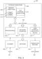
- FIG. 4is a simplified block diagram of a data processing system, in accordance with embodiments.
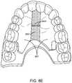
- FIG. 5illustrates an orthodontic appliance comprising a palatal expander portion within the mouth of a patient, in accordance with embodiments
- FIG. 6illustrates a top view of an appliance comprising a palate expander portion, a shell, and an extension structure joining the two together, in accordance with embodiments;
- FIG. 7illustrates an appliance which has been fabricated so as to avoid upwards pressure on a patient's palate, in accordance with embodiments
- FIG. 8 Aillustrates an appliance with palatal expander comprising a fabricated spring structure, in accordance with embodiments
- FIG. 8 Billustrates an appliance with palatal expander comprising a fabricated echelon-patterned spring structure, in accordance with embodiments
- FIG. 8 Cillustrates an appliance with palatal expander comprising a fabricated structure comprising compressible curved portions, in accordance with embodiments
- FIG. 8 Dillustrates an appliance with palatal expander comprising a fabricated jack structure comprising compressible hinged arms, in accordance with embodiments
- FIG. 8 Eillustrates an appliance with palatal expander comprising a material that expands upon contact with human saliva, in accordance with embodiments
- FIG. 9 Aillustrates a removable palatal expander fabricated to mate with an orthodontic appliance, in accordance with embodiments
- FIG. 9 Billustrates part of an aligner designed to mate with a palatal expander, in accordance with embodiments
- FIG. 9 Cillustrates a prototype orthodontic appliance comprising both a palatal expander and an aligner in accordance with embodiments, in accordance with embodiments;
- FIG. 9 Dillustrates a 3D model of an appliance comprising a palatal expander and an aligner in accordance with embodiments.
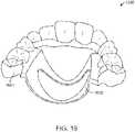
- FIG. 10shows an orthodontic appliance comprising a plastic aligner portion and a metallic palatal expander in accordance with embodiments.
- FIG. 11illustrates a variety of different arch expander designs that may be incorporated into an orthodontic appliance in accordance with embodiments
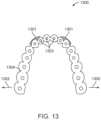
- FIG. 12illustrates a further embodiment in which an appliance may be fabricated with an arch expander comprising a connective portion to apply forces between distant teeth in accordance with embodiments;
- FIG. 13illustrates an aligner design that may be used in conjunction with the connective portion illustrated in FIG. 12 to guide a tooth movement
- FIG. 14 Aillustrates an example of an appliance having an anterior tab arch element, according to embodiments
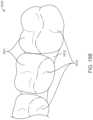
- FIG. 14 Billustrates an example of an appliance having a rib feature, according to embodiments
- FIG. 15 Aillustrates an arch expander having a removable connector component fabricated to mate with an orthodontic appliance, in accordance with embodiments
- FIG. 15 Billustrates part of an aligner designed to mate with a removable connector component, in accordance with embodiments
- FIG. 15 Cillustrates a prototype orthodontic appliance comprising both a removable connector and an aligner, in accordance with embodiments
- FIG. 15 Dillustrates a 3D model of an appliance comprising a removable connector component and an aligner, in accordance with embodiments.
- FIG. 16shows an orthodontic appliance comprising a plastic aligner portion and a metallic connector component, in accordance with embodiments.
- a directly fabricated orthodontic appliance for expanding a palate of a patientcomprises a teeth engagement portion comprising a plurality of teeth engagement structures and a force generating portion coupled to the teeth engagement portion.
- the force generating portioncomprises a hydratable polymer configured to expand when contacting saliva of the patient.
- the force generating portionis shaped to apply a palate-expanding force to the lateral sides of the palate of the patient when worn. In some embodiments, the force generating portion is configured to apply a palate-expanding force to the teeth engagement portion when worn, thereby applying a palate expanding force to the teeth of the patient. In some embodiments, the force generating portion is shaped to provide a gap between the top of the force generating portion and the palate when worn. In some cases, the teeth engagement portion and the force generating portion can comprise similar polymers with different amounts of crosslinking, the force generating portion comprising less crosslinking than the teeth engagement portion.
- a directly fabricated orthodontic appliance to expand a palate of a patientcomprises a teeth engagement portion comprising a plurality of teeth engagement structures and a directly fabricated resilient structure coupled to the teeth engagement portion.
- the resilient structurecomprises one or more of a spring, a leaf spring, a coil spring, or an elastic structure.
- a directly fabricated appliancefor expanding a palate of a patient.
- the appliancecomprises a teeth engagement component comprising a plurality of teeth receiving structures and a plurality of expander-engaging structures.
- the appliancefurther comprises an expander component comprising a plurality of engagement structures.
- the engagement structures of the expander componentengage corresponding expander-engaging structures of the teeth engagement component.
- the engagement between the expander component and the teeth engagement componentapplies a force to increase a size of the palate when worn by the patient.
- the respective engagement structuresare reversibly couplable, such that the expander portion is removable from the appliance.
- the appliancecomprises a sintered expander or a sintered teeth engagement component.
- the appliancecomprises both a sintered expander and a sintered teeth engagement component, and each of the teeth engagement component and the expander component comprise a respective sintered material independently selected from sintered metal, sintered plastic, or a combination thereof.
- an appliance to expand a palate of a patientcomprising a teeth engagement component comprising a plurality of teeth receiving structures and an expander component coupled to the teeth engagement component.
- the expander componentcomprises a shape-memory material that changes from a first configuration to a second configuration in response to a change in temperature.
- the applianceis configured to apply a greater palate expanding force in the first configuration than in the second configuration.
- the shape-memory materialtakes on the first configuration at about room temperature and takes on the second configuration at about human body temperature.
- the appliances described hereincan be shaped to be manually removable by the patient.
- the teeth engagement portions of the appliances described hereincan comprise a flattened occlusal surface for one or more molar-receiving structures.
- the appliances described hereincan be shaped to engage a temporary anchorage device in the palate of the patient to apply a palate expanding force when worn.
- the appliances described hereincan be configured to apply a tooth moving force to one or more anterior teeth of the upper arch while expanding the palate.
- the appliances described hereincan be configured to provide a palatal expansion selected from the group consisting of a slow palatal expansion and a rapid palatal expansion.
- the force generating portion of the appliances described hereinis configured to have a target palatal displacement, and to apply a palatal expansion force to expand the palate to the target palatal displacement.
- the target palatal displacementis adjustable.
- a plurality of the appliances described hereinare provided.
- the plurality of appliancesare configured to expand the palate when worn sequentially in accordance with a predetermined palate expansion plan.
- a method of fabricating an orthodontic applianceis provided.
- Scan data of an upper arch and a palate of a patientis received, and an amount of force to expand the palate is determined in response to the scan data.
- a shape profile of the appliance to engage teeth of the patientis determined and one or more of a force-generating or a resilient structure is selected to provide the force.
- Direct fabrication instructionsare output to manufacture the appliance with the teeth engaging structure and the force generating or resilient structure.
- determining the shape profileincludes determining a shape profile to inhibit contact with the top of the palate when worn.
- the shape profilecomprises an appliance shape to engage the lateral sides of the palate of the patient, and the amount of force comprises a first amount of force applied directly to the palate and a second amount of force applied to the teeth of the patient.
- the forcecan comprise a force applied to a temporary anchorage device.
- the resilient structurecomprises one or more of a spring, a leaf spring, a coil spring, or an elastic structure.
- the force generating portioncomprises one or more of a sintered plastic or a sintered metal comprising a material and size and shape profile arranged to increase a size of the palate and the teeth engaging portion comprises one or more of a sintered plastic or a sintered metal comprising a material and size and shape profile arranged to increase a size of the palate.
- the methodfurther comprises outputting direct fabrication instructions to manufacture a plurality of directly fabricated appliances configured to expand the palate in accordance with a predetermined palate expansion plan.
- the plurality of directly fabricated appliancesare further configured to move the teeth in accordance with a predetermined teeth movement treatment plan.
- the plurality of directly fabricated appliancescomprises a plurality of appliances configured to be placed on the teeth in series in accordance with a plurality of stages of a treatment plan.
- determining an amount of forcecomprises selecting a rate of palatal expansion based and determining a force to produce the selected rate of palatal expansion.
- the methodfurther comprises directly manufacturing the appliance according to the direct fabrication instructions.
- the direct fabrication instructionsinclude instructions to manufacture the appliance using an additive manufacturing process.
- the additive manufacturing processcomprises one or more of vat photopolymerization, material jetting, binder jetting, material extrusion, powder bed fusion, sheet lamination, or directed energy deposition.
- the direct fabrication instructionsinclude instructions to manufacture the appliance using a subtractive manufacturing process.
- the scan datacan include data of a temporary anchorage device in the palate of the patient and the shape profile comprises an engagement structure to engage the temporary anchorage device to apply a palate expanding force when the appliance is worn.
- an apparatus to expand an arch of a patientcomprises a force generating portion to expand the arch of the teeth, a flexible retention portion to hold the force generating portion on the teeth, and a stiff retention portion coupled to the flexible retention portion.
- the stiff retention portionis positioned adjacent to a first plurality of teeth receiving structures of the flexible retention portion to receive a first plurality of teeth.
- the stiff retention portionresists movement of the first plurality of teeth while allowing movement of a second plurality of teeth when the apparatus is worn.
- the force generating portion, the flexible retention portion, and the stiff retention portionhave been directly fabricated together.
- the force generating portioncomprises a stiff material.
- the force generating portioncomprises one or more of a compressible material or a resilient compressible structure to generate force to the teeth when placed.
- the stiff retention portioncomprises one or more ribs or thickened portions.
- the force generating portionspans the space between the bicuspid or molar teeth.
- the apparatuscomprises a plurality of materials.
- the force generating portioncomprises one or more of a compressible material, a hydratable material, or a resilient compressible structure to generate force to the teeth when worn.
- the flexible retention portioncomprises a plurality of teeth receiving structures, the plurality of teeth receiving structures comprising one or more of a plurality of teeth receiving cavities or a plurality of teeth receiving extensions shaped to extend at least partially around received teeth.
- the force generating portioncomprises adjacent stiff segments separated in a mesial-distal direction with an expansion force generating portion extending therebetween.
- the adjacent stiff segmentscomprise extensions sized to extend into interproximal portions to engage the teeth, and soft retention structures are affixed to the stiff segments and sized and shaped to extend around the teeth and into interproximal portions to engage the teeth and retain one or more stiff segments against the teeth.
- the apparatus described hereincomprise one or more of a thermoplastic polymer, a thermoset polymer, a polymer ceramic composite, a carbon fiber composite, or a combination thereof.
- the apparatusis further configured to apply a tooth moving force to one or more anterior teeth of the arch while expanding the arch.
- a method of fabricating an appliance to expand an arch of a patientScan data of teeth of an arch of the patient is received and a shape profile of the appliance to engage the teeth and expand the arch is determined.
- the appliancecomprises a force generating portion to expand the arch of the teeth, a flexible retention portion to hold the force generating portion on the teeth, and a stiff retention portion coupled to the flexible retention portion.
- the stiff retention portionis positioned adjacent to a first plurality of teeth receiving structures of the flexible retention portion to receive a first plurality of teeth, to resist movement of the first plurality of teeth while allowing movement of a second plurality of teeth when the apparatus is worn.
- Direct fabrication instructionsare output to manufacture the appliance with a direct fabrication apparatus.
- the methodfurther comprises determining an amount of force to expand the arch in response to the scan data and determining a shape of the force generating portion to provide the force to the teeth.
- the force generating portionis stiffer than the flexible retention portion.
- the force generating portioncomprises adjacent stiff segments separated in a mesial-distal direction with an expansion force generating portion extending therebetween.
- the applianceis configured to expand the arch with increasing separation of the adjacent stiff segments in a mesial-distal direction, and the adjacent stiff segments comprise extensions sized to extend into interproximal portions to engage the teeth.
- the appliancefurther comprises soft retention structures affixed to the stiff segments and sized and shaped to extend around the teeth and into interproximal portions to engage the teeth and retain one or more stiff segments against the teeth.
- the methodfurther comprises directly manufacturing the appliance according to the direct fabrication instructions.
- the direct fabrication instructionsinclude instructions to manufacture the appliance using an additive manufacturing process.
- the additive manufacturing processcomprises one or more of vat photopolymerization, material jetting, binder jetting, material extrusion, powder bed fusion, sheet lamination, or directed energy deposition.
- the direct fabrication instructionsinclude instructions to manufacture the appliance using a subtractive manufacturing process.
- an appliance to expand an arch of a patientcomprises a teeth engagement component comprising a plurality of teeth engagement structures and a force generating component coupled to the teeth engagement component.
- the teeth engagement componentcomprises a plurality of structures disposed on the lingual side of the teeth engagement component, and the force generating component comprises a plurality of engagement structures to engage the structures of the teeth engagement component to apply an arch expanding force.
- the force generating componentis a sintered metal or sintered plastic force generating component comprising a plurality of engagement structures to engage corresponding structures of the teeth engagement component with force in order to increase a size of the arch.
- the teeth engagement componentis a sintered metal or sintered plastic teeth engagement component.
- a and/or Bencompasses A alone, B alone, and A and B together.
- a “plurality of teeth”encompasses two or more teeth.
- one or more posterior teethcomprises one or more of a molar, a premolar or a canine, and one or more anterior teeth comprising one or more of a central incisor, a lateral incisor, a cuspid, a first bicuspid or a second bicuspid.
- the embodiments disclosed hereincan be used to couple groups of one or more teeth to each other.
- the groups of one or more teethmay comprise a first group of one or more anterior teeth and a second group of one or more posterior teeth.
- the first group of teethcan be coupled to the second group of teeth with the polymeric shell appliances as disclosed herein.
- the embodiments disclosed hereinare well suited for moving one or more teeth of the first group of one or more teeth or moving one or more of the second group of one or more teeth, and combinations thereof.
- the embodiments disclosed hereinare well suited for combination with one or known commercially available tooth moving components such as attachments and polymeric shell appliances.
- the appliance and one or more attachmentsare configured to move one or more teeth along a tooth movement vector comprising six degrees of freedom, in which three degrees of freedom are rotational and three degrees of freedom are translation.
- the present disclosureprovides orthodontic systems and related methods for designing and providing improved or more effective tooth moving systems for eliciting a desired tooth movement and/or repositioning teeth into a desired arrangement.
- an appliancecomprising a polymeric shell appliance
- the embodiments disclosed hereinare well suited for use with many appliances that receive teeth, for example appliances without one or more of polymers or shells.
- the appliancecan be fabricated with one or more of many materials such as metal, glass, reinforced fibers, carbon fiber, composites, reinforced composites, aluminum, biological materials, and combinations thereof for example.
- the reinforced compositescan comprise a polymer matrix reinforced with ceramic or metallic particles, for example.
- the appliancecan be shaped in many ways, such as with thermoforming or direct fabrication as described herein, for example. Alternatively or in combination, the appliance can be fabricated with machining such as an appliance fabricated from a block of material with computer numeric control machining.
- FIG. 1 Aillustrates an exemplary tooth repositioning appliance or aligner 100 that can be worn by a patient in order to achieve an incremental repositioning of individual teeth 102 in the jaw.
- the appliancecan include a shell (e.g., a continuous polymeric shell or a segmented shell) having teeth-receiving cavities that receive and resiliently reposition the teeth.
- An appliance or portion(s) thereofmay be indirectly fabricated using a physical model of teeth.
- an appliancee.g., polymeric appliance
- a physical applianceis directly fabricated, e.g., using rapid prototyping fabrication techniques, from a digital model of an appliance.
- An appliancecan fit over all teeth present in an upper or lower jaw, or less than all of the teeth.
- the appliancecan be designed specifically to accommodate the teeth of the patient (e.g., the topography of the tooth-receiving cavities matches the topography of the patient's teeth), and may be fabricated based on positive or negative models of the patient's teeth generated by impression, scanning, and the like.
- the appliancecan be a generic appliance configured to receive the teeth, but not necessarily shaped to match the topography of the patient's teeth.
- teeth received by an appliancewill be repositioned by the appliance while other teeth can provide a base or anchor region for holding the appliance in place as it applies force against the tooth or teeth targeted for repositioning. In some cases, some, most, or even all of the teeth will be repositioned at some point during treatment. Teeth that are moved can also serve as a base or anchor for holding the appliance as it is worn by the patient. Typically, no wires or other means will be provided for holding an appliance in place over the teeth. In some cases, however, it may be desirable or necessary to provide individual attachments or other anchoring elements 104 on teeth 102 with corresponding receptacles or apertures 106 in the appliance 100 so that the appliance can apply a selected force on the tooth.
- Exemplary appliancesincluding those utilized in the Invisalign® System, are described in numerous patents and patent applications assigned to Align Technology, Inc. including, for example, in U.S. Pat. Nos. 6,450,807, and 5,975,893, as well as on the company's website, which is accessible on the World Wide Web (see, e.g., the url “invisalign.com”).
- Examples of tooth-mounted attachments suitable for use with orthodontic appliancesare also described in patents and patent applications assigned to Align Technology, Inc., including, for example, U.S. Pat. Nos. 6,309,215 and 6,830,450.
- FIG. 1 Billustrates a tooth repositioning system 110 including a plurality of appliances 112 , 114 , 116 .
- Any of the appliances described hereincan be designed and/or provided as part of a set of a plurality of appliances used in a tooth repositioning system.
- Each appliancemay be configured so a tooth-receiving cavity has a geometry corresponding to an intermediate or final tooth arrangement intended for the appliance.
- the patient's teethcan be progressively repositioned from an initial tooth arrangement to a target tooth arrangement by placing a series of incremental position adjustment appliances over the patient's teeth.
- the tooth repositioning system 110can include a first appliance 112 corresponding to an initial tooth arrangement, one or more intermediate appliances 114 corresponding to one or more intermediate arrangements, and a final appliance 116 corresponding to a target arrangement.
- a target tooth arrangementcan be a planned final tooth arrangement selected for the patient's teeth at the end of all planned orthodontic treatment.
- a target arrangementcan be one of some intermediate arrangements for the patient's teeth during the course of orthodontic treatment, which may include various different treatment scenarios, including, but not limited to, instances where surgery is recommended, where interproximal reduction (IPR) is appropriate, where a progress check is scheduled, where anchor placement is best, where palatal expansion is desirable, where restorative dentistry is involved (e.g., inlays, onlays, crowns, bridges, implants, veneers, and the like), etc.
- IPRinterproximal reduction
- a target tooth arrangementcan be any planned resulting arrangement for the patient's teeth that follows one or more incremental repositioning stages.
- an initial tooth arrangementcan be any initial arrangement for the patient's teeth that is followed by one or more incremental repositioning stages.
- FIG. 1 Cillustrates a method 150 of orthodontic treatment using a plurality of appliances, in accordance with embodiments.
- the method 150can be practiced using any of the appliances or appliance sets described herein.
- a first orthodontic applianceis applied to a patient's teeth in order to reposition the teeth from a first tooth arrangement to a second tooth arrangement.
- a second orthodontic applianceis applied to the patient's teeth in order to reposition the teeth from the second tooth arrangement to a third tooth arrangement.
- the method 150can be repeated as necessary using any suitable number and combination of sequential appliances in order to incrementally reposition the patient's teeth from an initial arrangement to a target arrangement.
- the appliancescan be generated all at the same stage or in sets or batches (e.g., at the beginning of a stage of the treatment), or the appliances can be fabricated one at a time, and the patient can wear each appliance until the pressure of each appliance on the teeth can no longer be felt or until the maximum amount of expressed tooth movement for that given stage has been achieved.
- a plurality of different appliancese.g., a set
- the appliancesare generally not affixed to the teeth and the patient may place and replace the appliances at any time during the procedure (e.g., patient-removable appliances).
- the final appliance or several appliances in the seriesmay have a geometry or geometries selected to overcorrect the tooth arrangement.
- one or more appliancesmay have a geometry that would (if fully achieved) move individual teeth beyond the tooth arrangement that has been selected as the “final.”
- Such over-correctionmay be desirable in order to offset potential relapse after the repositioning method has been terminated (e.g., permit movement of individual teeth back toward their pre-corrected positions).
- Over-correctionmay also be beneficial to speed the rate of correction (e.g., an appliance with a geometry that is positioned beyond a desired intermediate or final position may shift the individual teeth toward the position at a greater rate). In such cases, the use of an appliance can be terminated before the teeth reach the positions defined by the appliance.
- over-correctionmay be deliberately applied in order to compensate for any inaccuracies or limitations of the appliance.
- the various embodiments of the orthodontic appliances presented hereincan be fabricated in a wide variety of ways.
- the orthodontic appliances herein (or portions thereof)can be produced using direct fabrication, such as additive manufacturing techniques (also referred to herein as “3D printing) or subtractive manufacturing techniques (e.g., milling).
- direct fabricationinvolves forming an object (e.g., an orthodontic appliance or a portion thereof) without using a physical template (e.g., mold, mask etc.) to define the object geometry.
- Additive manufacturing techniquescan be categorized as follows: (1) vat photopolymerization (e.g., stereolithography), in which an object is constructed layer by layer from a vat of liquid photopolymer resin; (2) material jetting, in which material is jetted onto a build platform using either a continuous or drop on demand (DOD) approach; (3) binder jetting, in which alternating layers of a build material (e.g., a powder-based material) and a binding material (e.g., a liquid binder) are deposited by a print head; (4) fused deposition modeling (FDM), in which material is drawn though a nozzle, heated, and deposited layer by layer; (5) powder bed fusion, including but not limited to direct metal laser sintering (DMLS), electron beam melting (EBM), selective heat sintering (SHS), selective laser melting (SLM), and selective laser sintering (SLS); (6) sheet lamination, including but not limited to laminated object manufacturing (LOM) and ultrasonic additive manufacturing (UA
- stereolithographycan be used to directly fabricate one or more of the appliances herein.
- stereolithographyinvolves selective polymerization of a photosensitive resin (e.g., a photopolymer) according to a desired cross-sectional shape using light (e.g., ultraviolet light).
- the object geometrycan be built up in a layer-by-layer fashion by sequentially polymerizing a plurality of object cross-sections.
- the appliances hereincan be directly fabricated using selective laser sintering.
- selective laser sinteringinvolves using a laser beam to selectively melt and fuse a layer of powdered material according to a desired cross-sectional shape in order to build up the object geometry.
- the appliances hereincan be directly fabricated by fused deposition modeling.
- fused deposition modelinginvolves melting and selectively depositing a thin filament of thermoplastic polymer in a layer-by-layer manner in order to form an object.
- material jettingcan be used to directly fabricate the appliances herein.
- material jettinginvolves jetting or extruding one or more materials onto a build surface in order to form successive layers of the object geometry.
- some embodiments of the appliances hereincan be produced using indirect fabrication techniques, such as by thermoforming over a positive or negative mold.
- Indirect fabrication of an orthodontic appliancecan involve producing a positive or negative mold of the patient's dentition in a target arrangement (e.g., by rapid prototyping, milling, etc.) and thermoforming one or more sheets of material over the mold in order to generate an appliance shell.
- the direct fabrication methods provided hereinbuild up the object geometry in a layer-by-layer fashion, with successive layers being formed in discrete build steps.
- direct fabrication methods that allow for continuous build-up of an object geometrycan be used, referred to herein as “continuous direct fabrication.”
- continuous direct fabricationVarious types of continuous direct fabrication methods can be used.
- the appliances hereinare fabricated using “continuous liquid interphase printing,” in which an object is continuously built up from a reservoir of photopolymerizable resin by forming a gradient of partially cured resin between the building surface of the object and a polymerization-inhibited “dead zone.”
- a semi-permeable membraneis used to control transport of a photopolymerization inhibitor (e.g., oxygen) into the dead zone in order to form the polymerization gradient.
- a photopolymerization inhibitore.g., oxygen
- Continuous liquid interphase printingcan achieve fabrication speeds about 25 times to about 100 times faster than other direct fabrication methods, and speeds about 1000 times faster can be achieved with the incorporation of cooling systems. Continuous liquid interphase printing is described in U.S. Patent Publication Nos. 2015/0097315, 2015/0097316, and 2015/0102532, the disclosures of each of which are incorporated herein by reference in their entirety.
- a continuous direct fabrication methodcan achieve continuous build-up of an object geometry by continuous movement of the build platform (e.g., along the vertical or Z-direction) during the irradiation phase, such that the hardening depth of the irradiated photopolymer is controlled by the movement speed. Accordingly, continuous polymerization of material on the build surface can be achieved.
- Such methodsare described in U.S. Pat. No. 7,892,474, the disclosure of which is incorporated herein by reference in its entirety.
- a continuous direct fabrication methodcan involve extruding a composite material composed of a curable liquid material surrounding a solid strand.
- the composite materialcan be extruded along a continuous three-dimensional path in order to form the object.
- a continuous direct fabrication methodutilizes a “heliolithography” approach in which the liquid photopolymer is cured with focused radiation while the build platform is continuously rotated and raised. Accordingly, the object geometry can be continuously built up along a spiral build path.
- a “heliolithography” approachin which the liquid photopolymer is cured with focused radiation while the build platform is continuously rotated and raised. Accordingly, the object geometry can be continuously built up along a spiral build path.
- the direct fabrication approaches provided hereinare compatible with a wide variety of materials, including but not limited to one or more of the following: a polyester, a co-polyester, a polycarbonate, a thermoplastic polyurethane, a polypropylene, a polyethylene, a polypropylene and polyethylene copolymer, an acrylic, a cyclic block copolymer, a polyetheretherketone, a polyamide, a polyethylene terephthalate, a polybutylene terephthalate, a polyetherimide, a polyethersulfone, a polytrimethylene terephthalate, a styrenic block copolymer (SBC), a silicone rubber, an elastomeric alloy, a thermoplastic elastomer (TPE), a thermoplastic vulcanizate (TPV) elastomer, a polyurethane elastomer, a block copolymer elastomer, a polyolefin blend
- the materials used for direct fabricationcan be provided in an uncured form (e.g., as a liquid, resin, powder, etc.) and can be cured (e.g., by photopolymerization, light curing, gas curing, laser curing, crosslinking, etc.) in order to form an orthodontic appliance or a portion thereof.
- the properties of the material before curingmay differ from the properties of the material after curing.
- the materials hereincan exhibit sufficient strength, stiffness, durability, biocompatibility, etc. for use in an orthodontic appliance.
- the post-curing properties of the materials usedcan be selected according to the desired properties for the corresponding portions of the appliance.
- relatively rigid portions of the orthodontic appliancecan be formed via direct fabrication using one or more of the following materials: a polyester, a co-polyester, a polycarbonate, a thermoplastic polyurethane, a polypropylene, a polyethylene, a polypropylene and polyethylene copolymer, an acrylic, a cyclic block copolymer, a polyetheretherketone, a polyamide, a polyethylene terephthalate, a polybutylene terephthalate, a polyetherimide, a polyethersulfone, and/or a polytrimethylene terephthalate.
- relatively elastic portions of the orthodontic appliancecan be formed via direct fabrication using one or more of the following materials: a styrenic block copolymer (SBC), a silicone rubber, an elastomeric alloy, a thermoplastic elastomer (TPE), a thermoplastic vulcanizate (TPV) elastomer, a polyurethane elastomer, a block copolymer elastomer, a polyolefin blend elastomer, a thermoplastic co-polyester elastomer, and/or a thermoplastic polyamide elastomer.
- SBCstyrenic block copolymer
- TPEthermoplastic elastomer
- TPVthermoplastic vulcanizate
- Machine parameterscan include curing parameters.
- curing parameterscan include power, curing time, and/or grayscale of the full image.
- curing parameterscan include power, speed, beam size, beam shape and/or power distribution of the beam.
- curing parameterscan include material drop size, viscosity, and/or curing power.
- gray scalecan be measured and calibrated before, during, and/or at the end of each build, and/or at predetermined time intervals (e.g., every n th build, once per hour, once per day, once per week, etc.), depending on the stability of the system.
- material properties and/or photo-characteristicscan be provided to the fabrication machine, and a machine process control module can use these parameters to adjust machine parameters (e.g., power, time, gray scale, etc.) to compensate for variability in material properties.
- a multi-material direct fabrication methodinvolves concurrently forming an object from multiple materials in a single manufacturing step.
- a multi-tip extrusion apparatuscan be used to selectively dispense multiple types of materials from distinct material supply sources in order to fabricate an object from a plurality of different materials.
- Such methodsare described in U.S. Pat. No. 6,749,414, the disclosure of which is incorporated herein by reference in its entirety.
- a multi-material direct fabrication methodcan involve forming an object from multiple materials in a plurality of sequential manufacturing steps.
- a first portion of the objectcan be formed from a first material in accordance with any of the direct fabrication methods herein, then a second portion of the object can be formed from a second material in accordance with methods herein, and so on, until the entirety of the object has been formed.
- Direct fabricationcan provide various advantages compared to other manufacturing approaches. For instance, in contrast to indirect fabrication, direct fabrication permits production of an orthodontic appliance without utilizing any molds or templates for shaping the appliance, thus reducing the number of manufacturing steps involved and improving the resolution and accuracy of the final appliance geometry. Additionally, direct fabrication permits precise control over the three-dimensional geometry of the appliance, such as the appliance thickness. Complex structures and/or auxiliary components can be formed integrally as a single piece with the appliance shell in a single manufacturing step, rather than being added to the shell in a separate manufacturing step.
- direct fabricationis used to produce appliance geometries that would be difficult to create using alternative manufacturing techniques, such as appliances with very small or fine features, complex geometric shapes, undercuts, interproximal structures, shells with variable thicknesses, and/or internal structures (e.g., for improving strength with reduced weight and material usage).
- the direct fabrication approaches hereinpermit fabrication of an orthodontic appliance with feature sizes of less than or equal to about 5 ⁇ m, or within a range from about 5 ⁇ m to about 50 ⁇ m, or within a range from about 20 ⁇ m to about 50 ⁇ m.
- the direct fabrication techniques described hereincan be used to produce appliances with substantially isotropic material properties, e.g., substantially the same or similar strengths along all directions.
- the direct fabrication approaches hereinpermit production of an orthodontic appliance with a strength that varies by no more than about 25%, about 20%, about 15%, about 10%, about 5%, about 1%, or about 0.5% along all directions. Additionally, the direct fabrication approaches herein can be used to produce orthodontic appliances at a faster speed compared to other manufacturing techniques.
- the direct fabrication approaches hereinallow for production of an orthodontic appliance in a time interval less than or equal to about 1 hour, about 30 minutes, about 25 minutes, about 20 minutes, about 15 minutes, about 10 minutes, about 5 minutes, about 4 minutes, about 3 minutes, about 2 minutes, about 1 minutes, or about 30 seconds.
- Such manufacturing speedsallow for rapid “chair-side” production of customized appliances, e.g., during a routine appointment or checkup.
- the direct fabrication methods described hereinimplement process controls for various machine parameters of a direct fabrication system or device in order to ensure that the resultant appliances are fabricated with a high degree of precision. Such precision can be beneficial for ensuring accurate delivery of a desired force system to the teeth in order to effectively elicit tooth movements.
- Process controlscan be implemented to account for process variability arising from multiple sources, such as the material properties, machine parameters, environmental variables, and/or post-processing parameters.
- Material propertiesmay vary depending on the properties of raw materials, purity of raw materials, and/or process variables during mixing of the raw materials.
- resins or other materials for direct fabricationshould be manufactured with tight process control to ensure little variability in photo-characteristics, material properties (e.g., viscosity, surface tension), physical properties (e.g., modulus, strength, elongation) and/or thermal properties (e.g., glass transition temperature, heat deflection temperature).
- Process control for a material manufacturing processcan be achieved with screening of raw materials for physical properties and/or control of temperature, humidity, and/or other process parameters during the mixing process. By implementing process controls for the material manufacturing procedure, reduced variability of process parameters and more uniform material properties for each batch of material can be achieved. Residual variability in material properties can be compensated with process control on the machine, as discussed further herein.
- Machine parameterscan include curing parameters.
- curing parameterscan include power, curing time, and/or grayscale of the full image.
- curing parameterscan include power, speed, beam size, beam shape and/or power distribution of the beam.
- curing parameterscan include material drop size, viscosity, and/or curing power.
- gray scalecan be measured and calibrated at the end of each build.
- material properties and/or photo-characteristicscan be provided to the fabrication machine, and a machine process control module can use these parameters to adjust machine parameters (e.g., power, time, gray scale, etc.) to compensate for variability in material properties.
- machine parameterse.g., power, time, gray scale, etc.
- environmental variablese.g., temperature, humidity, Sunlight or exposure to other energy/curing source
- machine parameterscan be adjusted to compensate for environmental variables.
- post-processing of appliancesincludes cleaning, post-curing, and/or support removal processes.
- Relevant post-processing parameterscan include purity of cleaning agent, cleaning pressure and/or temperature, cleaning time, post-curing energy and/or time, and/or consistency of support removal process. These parameters can be measured and adjusted as part of a process control scheme.
- appliance physical propertiescan be varied by modifying the post-processing parameters. Adjusting post-processing machine parameters can provide another way to compensate for variability in material properties and/or machine properties.
- the configuration of the orthodontic appliances hereincan be determined according to a treatment plan for a patient, e.g., a treatment plan involving successive administration of a plurality of appliances for incrementally repositioning teeth.
- Computer-based treatment planning and/or appliance manufacturing methodscan be used in order to facilitate the design and fabrication of appliances.
- one or more of the appliance components described hereincan be digitally designed and fabricated with the aid of computer-controlled manufacturing devices (e.g., computer numerical control (CNC) milling, computer-controlled rapid prototyping such as 3D printing, etc.).
- CNCcomputer numerical control
- the computer-based methods presented hereincan improve the accuracy, flexibility, and convenience of appliance fabrication.
- FIG. 2illustrates a method 200 for designing an orthodontic appliance to be produced by direct fabrication, in accordance with embodiments.
- the method 200can be applied to any embodiment of the orthodontic appliances described herein. Some or all of the steps of the method 200 can be performed by any suitable data processing system or device, e.g., one or more processors configured with suitable instructions.
- a movement path to move one or more teeth from an initial arrangement to a target arrangementis determined.
- the initial arrangementcan be determined from a mold or a scan of the patient's teeth or mouth tissue, e.g., using wax bites, direct contact scanning, x-ray imaging, tomographic imaging, sonographic imaging, and other techniques for obtaining information about the position and structure of the teeth, jaws, gums and other orthodontically relevant tissue.
- a digital data setcan be derived that represents the initial (e.g., pretreatment) arrangement of the patient's teeth and other tissues.
- the initial digital data setis processed to segment the tissue constituents from each other. For example, data structures that digitally represent individual tooth crowns can be produced.
- digital models of entire teethcan be produced, including measured or extrapolated hidden surfaces and root structures, as well as surrounding bone and soft tissue.
- the target arrangement of the teeth(e.g., a desired and intended end result of orthodontic treatment) can be received from a clinician in the form of a prescription, can be calculated from basic orthodontic principles, and/or can be extrapolated computationally from a clinical prescription.
- the final position and surface geometry of each toothcan be specified to form a complete model of the tooth arrangement at the desired end of treatment.
- a movement pathcan be defined for the motion of each tooth.
- the movement pathsare configured to move the teeth in the quickest fashion with the least amount of round-tripping to bring the teeth from their initial positions to their desired target positions.
- the tooth pathscan optionally be segmented, and the segments can be calculated so that each tooth's motion within a segment stays within threshold limits of linear and rotational translation.
- the end points of each path segmentcan constitute a clinically viable repositioning, and the aggregate of segment end points can constitute a clinically viable sequence of tooth positions, so that moving from one point to the next in the sequence does not result in a collision of teeth.
- a force system to produce movement of the one or more teeth along the movement pathis determined.
- a force systemcan include one or more forces and/or one or more torques. Different force systems can result in different types of tooth movement, such as tipping, translation, rotation, extrusion, intrusion, root movement, etc.
- Biomechanical principles, modeling techniques, force calculation/measurement techniques, and the like, including knowledge and approaches commonly used in orthodontia,may be used to determine the appropriate force system to be applied to the tooth to accomplish the tooth movement.
- sourcesmay be considered including literature, force systems determined by experimentation or virtual modeling, computer-based modeling, clinical experience, minimization of unwanted forces, etc.
- the determination of the force systemcan include constraints on the allowable forces, such as allowable directions and magnitudes, as well as desired motions to be brought about by the applied forces.
- allowable forcessuch as allowable directions and magnitudes
- desired motions to be brought about by the applied forcesFor example, in fabricating palatal expanders, different movement strategies may be desired for different patients.
- the amount of force needed to separate the palatecan depend on the age of the patient, as very young patients may not have a fully-formed suture.
- palatal expansioncan be accomplished with lower force magnitudes.
- Slower palatal movementcan also aid in growing bone to fill the expanding suture.
- a more rapid expansionmay be desired, which can be achieved by applying larger forces.
- the determination of the force systemcan also include modeling of the facial structure of the patient, such as the skeletal structure of the jaw and palate.
- Scan data of the palate and archsuch as Xray data or 3D optical scanning data, for example, can be used to determine parameters of the skeletal and muscular system of the patient's mouth, so as to determine forces sufficient to provide a desired expansion of the palate and/or arch.
- the thickness and/or density of the mid-palatal suturemay be measured, or input by a treating professional.
- the treating professionalcan select an appropriate treatment based on physiological characteristics of the patient.
- the properties of the palatemay also be estimated based on factors such as the patient's age—for example, young juvenile patients will typically require lower forces to expand the suture than older patients, as the suture has not yet fully formed.
- an arch or palate expander design for an orthodontic appliance configured to produce the force systemis determined. Determination of the arch or palate expander design, appliance geometry, material composition, and/or properties can be performed using a treatment or force application simulation environment.
- a simulation environmentcan include, e.g., computer modeling systems, biomechanical systems or apparatus, and the like.
- digital models of the appliance and/or teethcan be produced, such as finite element models.
- the finite element modelscan be created using computer program application software available from a variety of vendors.
- computer aided engineering (CAE) or computer aided design (CAD) programscan be used, such as the AutoCAD® software products available from Autodesk, Inc., of San Rafael, Calif.
- program products from a number of vendorscan be used, including finite element analysis packages from ANSYS, Inc., of Canonsburg, Pa., and SIMULIA(Abaqus) software products from Dassault Systémes of Waltham, Mass.
- one or more arch or palate expander designscan be selected for testing or force modeling.
- a desired tooth movementas well as a force system required or desired for eliciting the desired tooth movement, can be identified.
- a candidate arch or palate expander designcan be analyzed or modeled for determination of an actual force system resulting from use of the candidate appliance.
- One or more modificationscan optionally be made to a candidate appliance, and force modeling can be further analyzed as described, e.g., in order to iteratively determine an appliance design that produces the desired force system.
- step 240instructions for fabrication of the orthodontic appliance incorporating the arch or palate expander design are generated.
- the instructionscan be configured to control a fabrication system or device in order to produce the orthodontic appliance with the specified arch or palate expander design.
- the instructionsare configured for manufacturing the orthodontic appliance using direct fabrication (e.g., stereolithography, selective laser sintering, fused deposition modeling, 3D printing, continuous direct fabrication, multi-material direct fabrication, etc.), in accordance with the various methods presented herein.
- the instructionscan be configured for indirect fabrication of the appliance, e.g., by thermoforming.
- Method 200may comprise additional steps: 1) The upper arch and palate of the patient is scanned intraorally to generate three dimensional data of the palate and upper arch; 2) The three dimensional shape profile of the appliance is determined to provide a gap and teeth engagement structures as described herein.
- stepsshow a method 200 of designing an orthodontic appliance in accordance with some embodiments
- a person of ordinary skill in the artwill recognize some variations based on the teaching described herein. Some of the steps may comprise sub-steps. Some of the steps may be repeated as often as desired.
- One or more steps of the method 200may be performed with any suitable fabrication system or device, such as the embodiments described herein. Some of the steps may be optional, and the order of the steps can be varied as desired.
- FIG. 3illustrates a method 300 for digitally planning an orthodontic treatment and/or design or fabrication of an appliance, in accordance with embodiments.
- the method 300can be applied to any of the treatment procedures described herein and can be performed by any suitable data processing system.
- a digital representation of a patient's teethis received.
- the digital representationcan include surface topography data for the patient's intraoral cavity (including teeth, gingival tissues, etc.).
- the surface topography datacan be generated by directly scanning the intraoral cavity, a physical model (positive or negative) of the intraoral cavity, or an impression of the intraoral cavity, using a suitable scanning device (e.g., a handheld scanner, desktop scanner, etc.).
- one or more treatment stagesare generated based on the digital representation of the teeth.
- the treatment stagescan be incremental repositioning stages of an orthodontic treatment procedure designed to move one or more of the patient's teeth from an initial tooth arrangement to a target arrangement.
- the treatment stagescan be generated by determining the initial tooth arrangement indicated by the digital representation, determining a target tooth arrangement, and determining movement paths of one or more teeth in the initial arrangement necessary to achieve the target tooth arrangement.
- the movement pathcan be optimized based on minimizing the total distance moved, preventing collisions between teeth, avoiding tooth movements that are more difficult to achieve, or any other suitable criteria.
- At least one orthodontic applianceis fabricated based on the generated treatment stages.
- a set of appliancescan be fabricated, each shaped according a tooth arrangement specified by one of the treatment stages, such that the appliances can be sequentially worn by the patient to incrementally reposition the teeth from the initial arrangement to the target arrangement.
- the appliance setmay include one or more of the orthodontic appliances described herein.
- the fabrication of the appliancemay involve creating a digital model of the appliance to be used as input to a computer-controlled fabrication system.
- the appliancecan be formed using direct fabrication methods, indirect fabrication methods, or combinations thereof, as desired.
- design and/or fabrication of an orthodontic appliancemay include use of a representation of the patient's teeth (e.g., receive a digital representation of the patient's teeth 310 ), followed by design and/or fabrication of an orthodontic appliance based on a representation of the patient's teeth in the arrangement represented by the received representation.
- FIG. 4is a simplified block diagram of a data processing system 400 that may be used in executing methods and processes described herein.
- the data processing system 400typically includes at least one processor 402 that communicates with one or more peripheral devices via bus subsystem 404 .
- peripheral devicestypically include a storage subsystem 406 (memory subsystem 408 and file storage subsystem 414 ), a set of user interface input and output devices 418 , and an interface to outside networks 416 .
- This interfaceis shown schematically as “Network Interface” block 416 , and is coupled to corresponding interface devices in other data processing systems via communication network interface 424 .
- Data processing system 400can include, for example, one or more computers, such as a personal computer, workstation, mainframe, laptop, and the like.
- the user interface input devices 418are not limited to any particular device, and can typically include, for example, a keyboard, pointing device, mouse, scanner, interactive displays, touchpad, joysticks, etc.
- various user interface output devicescan be employed in a system of the invention, and can include, for example, one or more of a printer, display (e.g., visual, non-visual) system/subsystem, controller, projection device, audio output, and the like.
- Storage subsystem 406maintains the basic required programming, including computer readable media having instructions (e.g., operating instructions, etc.), and data constructs.
- the program modules discussed hereinare typically stored in storage subsystem 406 .
- Storage subsystem 406typically includes memory subsystem 408 and file storage subsystem 414 .
- Memory subsystem 408typically includes a number of memories (e.g., RAM 410 , ROM 412 , etc.) including computer readable memory for storage of fixed instructions, instructions and data during program execution, basic input/output system, etc.
- File storage subsystem 414provides persistent (non-volatile) storage for program and data files, and can include one or more removable or fixed drives or media, hard disk, floppy disk, CD-ROM, DVD, optical drives, and the like.
- One or more of the storage systems, drives, etcmay be located at a remote location, such coupled via a server on a network or via the internet/World Wide Web.
- bus subsystemis used generically so as to include any mechanism for letting the various components and subsystems communicate with each other as intended and can include a variety of suitable components/systems that would be known or recognized as suitable for use therein. It will be recognized that various components of the system can be, but need not necessarily be at the same physical location, but could be connected via various local-area or wide-area network media, transmission systems, etc.
- Scanner 420includes any means for obtaining a digital representation (e.g., images, surface topography data, etc.) of a patient's teeth (e.g., by scanning physical models of the teeth such as casts 421 , by scanning impressions taken of the teeth, or by directly scanning the intraoral cavity), which can be obtained either from the patient or from treating professional, such as an orthodontist, and includes means of providing the digital representation to data processing system 400 for further processing.
- Scanner 420may be located at a location remote with respect to other components of the system and can communicate image data and/or information to data processing system 400 , for example, via a network interface 424 .
- Fabrication system 422fabricates appliances 423 based on a treatment plan, including data set information received from data processing system 400 .
- Fabrication machine 422can, for example, be located at a remote location and receive data set information from data processing system 400 via network interface 424 .
- Data processing aspects of the methods described hereincan be implemented in digital electronic circuitry, or in computer hardware, firmware, software, or suitable combinations thereof.
- Data processing apparatuscan be implemented in a computer program product tangibly embodied in a machine-readable storage device for execution by a programmable processor. Data processing steps can be performed by a programmable processor executing program instructions to perform functions by operating on input data and generating output.
- the data processing aspectscan be implemented in one or more computer programs that are executable on a programmable system, the system including one or more programmable processors operably coupled to a data storage system.
- a processorwill receive instructions and data from a read-only memory and/or a random access memory.
- Storage devices suitable for tangibly embodying computer program instructions and datainclude all forms of nonvolatile memory, such as: semiconductor memory devices, such as EPROM, EEPROM, and flash memory devices; magnetic disks such as internal hard disks and removable disks; magneto-optical disks; and CD-ROM disks.
- semiconductor memory devicessuch as EPROM, EEPROM, and flash memory devices
- magnetic diskssuch as internal hard disks and removable disks
- magneto-optical diskssuch as CD-ROM disks.
- FIG. 5illustrates an orthodontic appliance 500 comprising a palatal expander portion 501 within the mouth of a patient.
- the appliance 500comprises a teeth engaging portion having a plurality of tooth-receiving cavities 502 configured to receive teeth.
- a gap 507can extend between the upper portion of the palate and the upper portion of appliance 500 when placed in the mouth of the patient.
- the teeth engaging portioncan be similar to commercially available tooth repositioning appliances comprising transparent shell portions to reposition teeth.
- the teeth engaging portioncan be configured to resiliently reposition the patient's teeth 503 .
- a palatal expandermay apply force generating orthodontic forces 505 against groups of one or more teeth on opposite sides of a patient's mouth, in order to cause the patient's palate 504 to expand.
- an expansion 506 of the expander portion 501may be caused by an expansion 506 of the expander portion 501 .
- An extension portion 506can extend between the expander portion 501 and the teeth engaging portion comprising cavities 502 in order to couple the expander portion 501 with the teeth engaging portion.
- this expansion of palate 504may coincide with an increase in distance between teeth 503 on opposite sides of the patient's mouth.
- Palate expansiontypically requires stronger forces and larger-scale movements than those typically used for orthodontic movement of single teeth, presenting unique challenges in designing palate expanders.
- the challenges that must be overcomeare the design of a palate expander capable of providing strong forces without damage as well as preventing or minimizing distortions, such as may cause uncomfortable upward pressure between the expander portion 501 and the palate 504 .
- the force 505 applied to the teeth 503may tend to cause an undesired tipping movement, in which the teeth 503 are tilted outwards as a reaction to the applied force from the aligner.
- the extension portion 506may be shaped to contact portions of the patient's palate, such at locations 508 and 509 , so as to apply force to the palate directly in addition to the forces applied to the teeth 503 .
- an implantable devicesuch as a temporary anchorage device (TAD) may be provided in the patient's palate, such as at locations 508 and 509 .
- the TADcan be embedded into or attached to the bone of the patient's palate so as to transmit force directly from the appliance to the patient's palate.
- the appliancecan be shaped with surface portions configured to receive the TAD, such as a hook or socket for example.
- the locations of points 508 and 509can be varied as needed to distribute appropriate force; for example, the locations can be selected by a treating professional or a computer model of the patient's palate and dentition.
- the TADsare located on the roof of the palate on opposite sides of the suture, and the appliance is shaped to engage the TADs to apply a palate-expanding force.
- Multiple points of contactincluding continuous contact surfaces, may also be used for direct palate contact and/or contact with a TAD. This allows the total palate-separating force to be distributed over multiple surfaces, decreasing the amount of force any particular surface must bear.
- the force on the teeth 503can comprise only a portion of the total palate expanding force, reducing the likelihood of inducing tipping movement.
- An orthodontic appliance 500comprising a palatal expander shaped to apply force both to the palate and to the teeth can be readily designed for fabrication using the methods disclosed herein.
- the force systemcan include forces applied to both teeth and palate areas to induce a palatal expansion.
- a fabrication design for extension portion 506can include material shaped to contact portions of the palate along the left and/or right arching parts of the palate, such as around areas 508 and 509 of the palate, for example. Contact to the top of the palate may be limited in the palate-expansion forces it can apply, while potentially causing discomfort to the patient. Accordingly, contact between the top of the palate and the appliance when worn is not required.
- the appliancecan be shaped to contact to the top of the palate
- the appliancecan also be shaped to provide a gap 507 .
- This gapneed not inhibit contact between the lateral portions of the palate and the appliance, such that palatal expansion forces can be applied to the sides of the palate without requiring contact with the top of the palate.
- the appliancecan be shaped such that contact areas 508 and 509 are spread out over a large area of the palate, applying more uniform pressure across the contact areas while applying less localized pressure to the palate when the appliance is worn.
- Direct fabricationallows the use of a wide range of materials and structures, which may be combined in a variety of ways when designing appliance structures such as palate expanders
- traditional structures used in palate expanderssuch as manually-adjusted screws may be directly fabricated as well as augmented with further structures as described herein.
- traditional structuressuch as screws or springs may be used in the appliances disclosed herein without being directly fabricated.
- palate expandersmay be fabricated without the need for manual adjustments, for example by incorporating, within the expander portion 501 , rigid materials that expand when contacted with saliva, such as hydrophilic polymers, for example. Other materials with similar expansion properties, such as high rigidity and swelling capacity, may be selected to customize the expansion, as will be appreciated by a person of ordinary skill in the art.
- expander portion 501can comprise a thermoplastic or thermoset material, for example.
- FIG. 6illustrates a top view of an appliance 600 .
- Appliance 600may comprise many of the features and structures of appliance 500 , for example.
- Appliance 600comprises a palate expander portion 601 , a shell 602 , and an extension structure 603 joining the two together. Expansion of palate expander 601 provides force generating forces on shell 602 , transmitted by extension structure 603 . When worn by a patient, this may cause an expansion of a patient's palate, as illustrated in corresponding appliance 500 in FIG. 5 .
- appliance 600may be fabricated as a single structure, wherein palate expander 601 , shell 602 , and extension structure 603 may comprise different materials.
- palate expander 601may connect directly to shell 602 , omitting extension structure 603 .
- palate expander 601may comprise a plurality of materials, and additionally or alternatively, shell 602 and extension structure 603 may each also comprise one or more materials. The size, structure, and materials of palate expander 601 , shell 602 , and extension structure 603 may be varied to customize the force generating force produced.
- palate expander 601 , shell 602 , and extension structure 603may comprise the same material; for example, in some cases in which palate expander 601 comprises a fabricated spring or screw structure.
- palate expander 601may comprise a material that expands upon contact with a patient's saliva, permitting it to spontaneously begin applying force after being placed in a patient's mouth.
- the amount of force appliedwill depend on variables that may be controlled during fabrication, such as the size of the palate expander 601 and choice of material from which it is fabricated. Generally, larger palate expanders may cause larger forces, and more force generating materials may likewise generating larger forces.
- the size of the palate expandermay be varied during fabrication, for example by making it larger in a horizontal axis while making extension structure 603 correspondingly shorter in that axis.
- the expansiveness of the material comprising palate expander 601may be varied in a variety of ways, such as by switching to a material of different expansiveness or by employing a plurality of materials that expand differently.
- a palate expander made of composite material uniformly comprising equal amounts of force generating and non-force generating polymerwill provide less force than a similar palate expander made entirely of the force generating polymer Similar effects can be generated using other non-polymer materials.
- the forcemay be tuned as desired by varying the proportions of different polymers or other materials in this manner.
- material expansioncan also be controlled by choosing polymers with different amounts of cross-linking, with more cross-linking leading to smaller amounts of expansion.
- a palate expansion applianceAnother consideration when designing a palate expansion appliance is the avoidance of upward pressure on the patient's palate. If a palate expander expands too much in a vertical direction, it may put pressure on the patient's palate, which may prove uncomfortable. Horizontal expansion may also indirectly cause uncomfortable pressure in some cases, such as when it causes upward flexing of the appliance.
- the material properties of a fabricated palate expandermay be designed so as to relieve this potential problem.
- FIG. 7illustrates an appliance 700 which has been fabricated so as to inhibit contact with and avoid upwards pressure on a patient's palate, with a gap extending between the upper portion of the palate and the upper portion of the appliance as described herein.
- the palate expander appliance 700comprises a palate expander 701 comprising a plurality of materials, arranged into a plurality of layers. As illustrated, the plurality of layers comprises an upper layer 702 that is configured to inhibit contact with the patient's palate and a lower layer 703 underneath. These two layers are both attached to appliance shell 704 , wherein the connection may be direct or may comprise an extension structure as described herein.
- the materials of layers 702 and 703are chosen to expand at different rates—for example, upper layer 702 may comprise a material with lower swelling capacity than the material of layer 703 .
- This difference between materialsmay, for example, be controlled by fabricating the different layers from polymeric material with different amounts of cross-linking, thereby varying the swelling capacity. For example, materials with more cross-linking can have enhanced stiffness, and thereby resist swelling, whereas materials with less cross-linking can have reduced stiffness, thereby increasing swelling.
- forces 712 and 713wherein forces 713 are greater in magnitude than forces 712 .
- the bending 714can also be used to apply contact forces on the lateral sides of the palate, such that force on the roof of the mouth is diminished while force on the sides of the palate and on the teeth is increased, thereby providing a combined palate expansion force.
- the magnitude of palate contact forcecan be adjusted by selecting an appropriate shape and thickness of upper layer 702 near the contact points, as well as appropriately selecting lower layer 703 to provide the desired expansion movement.
- Further layered structuresmay be contemplated, comprising a plurality of layers of different swelling capacities. Alternatively or additionally, the layered structure may vary its swelling capacity continuously along axes, such as a vertical axis and/or a horizontal axis.
- FIGS. 8 A-Eillustrate a few of the many optional palate expander structures which may be fabricated using direct fabrication techniques as described herein.
- the structures depicted in FIGS. 8 A-Emay be fabricated as part of an appliance further comprising tooth-receiving structures such as concavities.
- These embodimentsshow directly fabricated resilient structures configured to urge teeth on opposite sides of the arch away from each other.
- the tooth receiving engagement structures comprising concavitiescan be shaped to receive teeth on the lingual side closer to the gingival portion than the occlusal portion.
- the appliancesmay comprise interproximal engagement structures to extend at least partially into interproximal spaces of the patient's teeth to improve retention. In many embodiments, these appliances can be retained on the patient's teeth with a low profile configuration without extending to both sides of each of the teeth.
- These appliancescan be configured to provide a gap as described herein.
- FIG. 8 Aillustrates an appliance with palatal expander comprising a directly fabricated spring structure 801 .
- the palatal expanderis shown placed on the patient's teeth.
- the spring structure 801comprises a plurality of compressible structures 802 .
- the compressible structures 802are compressed, storing elastic potential energy. This stored potential energy results in an outward force to induce a palate expansion.
- FIG. 8 Billustrates an appliance with palatal expander comprising a directly fabricated echelon-patterned and/or chevron patterned spring structure 811 .
- the palatal expanderis shown placed on the patient's teeth.
- the echelon structures comprising echelon-patterned spring structure 811may be directly fabricated out of compressible material that will bend when placed in the patient's mouth. This bending stores elastic potential energy that results in an outward force to induce a palate expansion.
- FIG. 8 Cillustrates an appliance with palatal expander comprising a fabricated structure 821 comprising compressible curved portions 822 .
- the palatal expanderis shown placed on the patient's teeth.
- the curved structures 822may be fabricated out of compressible material that will bend when placed in the patient's mouth. This bending stores elastic potential energy that results in an outward force to induce a palate expansion.
- FIG. 8 Dillustrates an appliance with palatal expander comprising a fabricated jack structure 831 comprising compressible hinged arms 832 .
- the palatal expanderis shown placed on the patient's teeth.
- Opposite ends of hinged arms 832are connected by an elastic band 833 , applying an inward force 835 to opposite ends of the arms together.
- This inward forceproduces a motion as hinged arms rotate about hinges 834 , which may be fabricated as part of structure 831 .
- An outward force 836results as the structure expands in the image's horizontal axis while compressing in the image's vertical axis.
- Forcecan be applied at the hinges, for example using a rubber band, to compress the jack structure and apply a palate-expanding force.
- the force generating components disclosed hereincan generate forces based on a target palatal displacement.
- an amount of palatal expansioncan be selected, and the force generating component can be fabricated such that an expansion force is generated when the appliance is worn, so long as the amount of palatal expansion is less than the target palatal displacement.
- an appliancecan generate palatal expansion forces without causing excessive expansion.
- the target palatal displacementcan be adjustable; for example, adjustable screws, springs, bands, or other components can be adjusted to change the size of the palatal expander, thereby changing the target palatal displacement.
- An adjustable palatal expandercan be used to generate a slow palatal expansion, for example.
- FIG. 8 Eillustrates an appliance with palatal expander comprising a material that expands upon contact with human saliva.
- the palatal expanderis shown placed on the patient's teeth.
- Outer portions 841 of the applianceare comprises a rigid material that does not expand, while an inner portion such as central portion 842 comprises a rigid material with a high swelling capacity such that it expands within a patient's mouth as it absorbs water from a patient's saliva.
- the expansioncauses outwards forces 843 that may be used to induce a palate expansion.
- central portion 842comprises a plurality of layers or a material with continuously varied swelling capacity.
- the inner portion such as central portion 842comprises an elastic material capable of being compressed upon insertion to generate the force to the teeth to expand the palate.
- the materialcan be shaped with structures such as voids to provide flexibility and compressibility to the material, similar to closed cell foam and open cell foam to provide a compressible force generating structure.
- a plurality of resilient structures as describedcan be formed on a small scale, for example no more than about 2 mm across, in order to provide the force generating portion.
- the forces produced by the appliances disclosed hereincan be varied by changing the size, shape, mass, and elasticity of the materials used in the expanders, individually or in combination.
- aligners and palatal expandersmay be directly fabricated as separate components to be fit together later for use.
- the palate expandercomprises a force generating component as disclosed herein and the aligner comprises a teeth engagement structure as disclosed herein.
- the separate componentsmay comprises corresponding engagement structures that allow the components to fit together and hold the aligner and palate expander together when placed in the mouth of the patient.
- the corresponding engagement structurescan be configured in many ways and may comprise one or more of locking structures, a protrusion sized to extend into a receiving structure such as a recess, nested structures or locking structures.
- the aligner and plate expandermay comprise corresponding shape profiles that allow the corresponding structures of the palate expander to aligner to fit together and be held in place.
- the corresponding structurescan be configured for the engagement structures to gently snap in place, for example.
- the usercan be provided with a plurality of pieces to snap in place over the course of a treatment plan of palate expansion, for example.
- each of the palate expander and alignercan optionally be composed of multiple, separately fabricated parts.
- an alignercan comprise a left and right portion to fit the left and right dental arches, or left, right, and center portions to fit respective left, right, and central teeth of an arch. These portions can be fabricated as a single unit that can be separated and reattached, or they can be fabricated separately for attachment thereafter.
- the palate expandercan be fabricated in one, two, three, or more separate parts that can be joined together, such as with the joining methods disclosed herein. In some cases, for example, each part, or certain parts, can be fabricated from different materials so as to possess different properties such as stiffness.
- FIG. 9 Aillustrates a removable palatal expander 900 fabricated to mate with an orthodontic appliance.
- the palatal expander 900comprises an arch component 901 fabricated from elastic material to fit the palate of a patient. The material may be fabricated to be larger than the patient's palatal region, so that it compresses when worn, permitting an outward force to be applied to a patient's teeth.
- the palatal expander 900further comprises a ridged portion 902 on each side designed to conform to the surface of an orthodontic appliance.
- the rigid portion 902may comprises protrusions sized and shaped to extend toward interproximal the space of the teeth when engaging corresponding structures of the teeth engaging appliance.
- indentations 903may be located in the ridged portion 902 configured to mate with protrusions on the appliance.
- FIG. 9 Billustrates part of an aligner 910 designed to mate with a palatal expander as shown in FIG. 9 A .
- the aligner 910comprises a plurality of teeth engagement structures comprising a plurality of teeth receiving cavities 911 sized and shaped to engage the teeth for palate expansion.
- the alignercomprises plurality of tooth-receiving cavities 911 , as well as a labial contour 912 .
- the labial contour 912matches the corresponding ridged portion 902 of the palatal expander.
- the teeth engaging aligner componentfurther comprises protrusions 913 configured to engage, for example mate, with the corresponding indentations 903 of the palatal expander 900 .
- the protrusions 913can be located on a labial side of the teeth.
- the teeth engaging aligner componentmay comprise receiving structures shaped to receive the protrusions of the rigid portion 902 of the arch component 901 . This arrangement allows the palatal expander 900 and the aligner 910 to hold together, for example to securely mate together.
- the aligner 910can be configured to move teeth in accordance with a treatment plan as described herein.
- the arch component 901can be configured to move the palate in accordance with a palate expansion plan.
- the teeth engagement structures that couple to the teethcan be configured in many ways. Although an aligner is shown, other structures as described herein can be used to engage the teeth and couple to the palate expander in order to engage the teeth.
- the occlusal surface above the teeth receiving cavitiescan be shaped to simulate the occlusal surfaces of teeth, as shown in FIG. 9 C , showing a surface with varying height similar to that of ordinary tooth surfaces.
- portions of the occlusal surfaces of some or all teeth receiving cavitiescan be provided with a flatter surface.
- the left and right archescan move more freely in lateral directions.
- the expansion of the palatewill be less inhibited by the engagement of the upper and lower arches, allowing less force to be needed.
- FIG. 9 Cshow a picture of a directly fabricated orthodontic appliance 920 comprising both a palatal expander 900 and an aligner 910 .
- the palatal expander and alignerare made of different materials, with the palatal expander capable of flexing when worn to store elastic energy, thereby applying force to a patient's teeth.
- the palate expander componentcomprises an unloaded free standing configuration with the engagement structures such as protrusion having a separation distance on opposing sides of the expander sized larger than corresponding structures of opposing sides of the arch of the aligner.
- a 3D computer model 930 of appliance 920which may for example be generated when designing an orthodontic appliance according to methods 200 or 300 , is illustrated in FIG. 9 D .
- a person of ordinary skill in the artcan use computer modeling and experimentation to determine the forces to the teeth appropriate for palate expansion, and determine the size, shape and material as described herein.
- the palate expander componentcan be sized to inhibit or avoid contact with part or all of the palate in response to an oral scan or dental impression to generate three dimensional profile data of the mouth as described herein.
- the palate expander componentcan be also be sized to selectively contact portions of the palate to apply palate-expanding forces, which may be distributed over parts of the left and right palatal arches of a patient so as to decrease load on the teeth of the patient.
- the amount of force applied by appliance 920is affected by the ridges illustrated in the center of the arch.
- the ridges on the applianceincrease the stiffness of the expander, which can be used to vary the expansion force applied. For example, adding thick ridges can produce a stiff arch that applies forces over a short range, whereas thinner or missing ridges can produce a more resilient shape that applies forces over a longer range.
- FIG. 10shows a design of an orthodontic appliance 1000 comprising a plastic aligner component 1001 and a metallic palatal expander 1002 .
- the use of metal materialsoffer a number of advantages, such as greater applicable force, lack of stress relaxation, durability, corrosion resistance, and easy sterilization. Biocompatibility is also readily achieved, since the use of metallic material in orthodontics is already used in the dental industry, and the selection of appropriate metals will be apparent to one of ordinary skill in the art.
- Metallic alignersmay be usefully fabricated using direct fabrication techniques such as Direct Metal Laser Sintering (DMLS), Electon-Beam Sintering, or Selective Laser Sintering, and in some cases may be fabricated directly along with a directly fabricated plastic aligner component.
- DMLSDirect Metal Laser Sintering
- Electon-Beam SinteringElecton-Beam Sintering
- Selective Laser SinteringSelective Laser Sintering
- multiple direct fabrication techniquesmay be used in combination, such as by fabricating separate parts using separate techniques, such that the parts can be assembled into an appliance.
- the force applied by orthodontic appliance 1000can be readily controlled by the thickness and topology of the metallic expander 1002 .
- the metallic expander 1002comprises an arch with a circular hole, such that the amount of metal is less than would be present in a solid metallic arch.
- the expanding forceis correspondingly reduced.
- the size or shape of the hole of expander 1002the expanding force can be increased or decreased as needed; similarly, the thickness of the metal can be varied, with thinner metal arches applying less force.
- the shape and number of holescan also be varied to tune the force; for example, shapes such as those illustrated in FIGS. 8 A- 8 D can be employed.
- a further expander designcan employ a shape-memory material such as a shape-memory alloy or a shape-memory polymer that responds to temperature by altering its shape.
- the appliancecan be prepared such that the expander has a first shape at a cold temperature, such as room temperature, and a second shape at warm temperature, such as human body temperature.
- the first shapecan be selected to fit in a patient's mouth without applying significant expanding forces, while the second shape can be selected to have a larger width than the first shape, such that at a warmer temperature, the expander applies an outwards force on the teeth to expand the palate and/or the arch of the patient.
- the appliancecan be placed in the mouth at room temperature without applying excessive force, and then increase force continuously as the appliance heats to body temperature in the mouth.
- the appliances disclosed hereinmay have a stiff inner component and a soft outer component.
- the arch expandermay comprise adjacent stiff portions extending in mesial distal directions with a gap extending therebetween.
- the gapmay have a spring or other expansion device, e.g. polymer to urge opposing blocks of teeth against each other. Upon compression shown with arrows, the force generating structure of the gap can urge the adjacent sections apart to move the teeth.
- Embodimentscan have soft material extending around circumference of teeth to provide placement. Exposed occlusal surface can provide improved inter digitation with tooth movement. This arch expander can also be used to align teeth.
- the force generating structurecan be built in and directly fabricated, for example as an expander with spring feature at the gap in stiff elongate portions to cause expansion.
- the distal teethmay comprise anchoring molars to facilitate movement of the anterior teeth on an opposite side of the gap comprising the expandable structure.
- the archcan be expanded with increasing separation of the elongate stiff segments having the gap extending therebetween.
- FIG. 11illustrates a variety of different arch expander designs that may be incorporated into an orthodontic appliance, for example when designing an appliance in method 200 .
- Arch expanders 1111 , 1121 , and 1131are shown incorporated into orthodontic appliances 1110 , 1120 , and 1130 respectively.
- Appliances 1110 , 1120 , and 1130each comprise tooth-receiving structures 1112 , 1122 , and 1132 , respectively, such as cavities, designed to receive one or more of teeth 1113 , 1123 , and 1133 , respectively.
- tooth-receiving structures 1112 , 1122 , and 1132may comprise a soft material, including possibly a soft clear material.
- arch expanders 1111 , 1121 , and 1131may comprise a rigid material, which typically need not be clear, but may optionally be clear as well.
- the tooth-receiving structures 1112 , 1122 , and 1132serve to hold appliances 1110 , 1120 , and 1130 on teeth 1113 , 1123 , and 1133 , respectively, allowing respective arch expanders 1111 , 1121 , and 1131 to apply tooth moving forces such as arch expanding forces.
- the teeth engagement structures of the stiff portioncan extend into interproximal spaces of the teeth to improve fit and force coupling, for example.
- an arch expanderwill be used to expand a dental arch comprising a plurality of teeth, such as teeth 1113 .
- This expansionmay comprise a movement of a plurality of teeth in different directions; for example, teeth on opposite medial sides of the mouth may be moved apart.
- posterior and anterior teethmay be moved away from each other, so that the overall shape of the dental arch is changed. This type of movement may be useful, for example, in the reduction of tooth crowding, or for other suitable purposes.
- arch expander 1111may be broken into different segments, separated by gaps 1114 . As illustrated, forces may be applied between the separate segments, for example, using material inserted into the gaps 1114 .
- the gapsmay be bridged by one or more screws, which may be rotated in one direction to drive the segments of arch expander 1111 apart, or in the other direction to pull the segments together.
- the screwsmay be fabricated as part of the appliance fabrication process, or installed separately using known machining techniques.
- springsmay be installed to connect across the gaps 1114 , to apply spring forces on arch expander 1111 .
- the forces applied by the springsmay be varied, optionally including forces tending to push segments apart and/or to pull them together, as desired.
- the springsmay in some cases be fabricated separately and attached to the arch expander 1111 and in some cases may be fabricated along with the arch expander. A combination of springs fabricated separately and as part of the arch expander fabrication process may also be used, as desired.
- structuressuch as bars may connect one or more of the segments of arch expander 1111 to apply force. These bar structures may likewise be fabricated as part of the arch expander 1111 or attached separately.
- an arch expanding forcemay be exerted between segments by fabricating arch expander 1111 with gaps 1114 filled with a compressible material.
- an arch expanding forcemay be applied as the compressed material in the gaps 1114 pushes outward on the segments of arch expander 1111 .
- rigid material in gaps 1114may be designed so that it changes its properties in response to being placed in a patient's mouth.
- the materialmay expand in response to contact with the patient's saliva, such as may be the case in materials such as hydrophilic polymers, for example.
- Suitable materials for use in this mannermay exhibit both high rigidity and swelling capacity. This expansion may be tailored by varying the properties of the material, including the amount of expansion per unit volume and the shape and size of the gaps 1114 , as well as the fraction of the gaps in which the material is placed.
- larger gaps 1114 filled with material with higher swelling capacitymay provide more arch expanding force, because the amount of arch expansion force that may be caused by material filling the gaps 1114 grows in proportion to the size of the gaps, as well as to the fraction of the gaps (along the lingual-buccal and/or vertical directions) that has been filled.
- a further use of material that expands in response to contact with a patient's salivais to incorporate the material continuously throughout a solid arch expander.
- Arch expanders 1121 and 1131may comprise the expandable material for example.
- This design of the arch expanderallows for nearly arbitrary control over the forces applied to teeth 1123 or 1133 . For example, if one or more particular teeth are to be singled out for greater applied force, additional expandable material may be added on one side of the one or more teeth, wherein the extra expansion of that material may apply a greater force to push the one or more teeth away from the material.
- the distribution of materialmay be chosen as desired to apply a wide range of customizable forces on teeth 1123 or 1133 .
- Thismay be used, for example, to guide the teeth individually or in independent groups along a desired trajectory, while expanding the dental arch, for example. Further optional combination may be made with materials having different degrees or rigidity or of swelling capacity along different axes to enable further customization of available forces comprising a plurality of magnitudes and a plurality of directions on each of a plurality of teeth.
- the material of the tooth-receiving structuresmay be chosen independently of the material of the arch expander.
- tooth-receiving structuresmay comprise soft and/or clear material whereas the arch expander may comprise hard and/or non-clear material.
- the tooth-receiving structuresthemselves may be made of more than one material, wherein a first and a second set of tooth-receiving structures comprise a first and a second material.
- tooth-receiving structures configured to receive molarsmay be fabricated with a different material than those configured to receive incisors.
- the tooth-receiving structuresmay also be designed to engage different teeth in many ways.
- appliance 1110comprises tooth-receiving structures 1112 that cover the occlusal surfaces of their respective teeth
- appliance 1120comprises tooth-receiving structures 1122 that extend substantially around and may surround the outer portion of their respective teeth while leaving the occlusal surfaces uncovered.
- appliance 1130comprises tooth-receiving structures 1132 of both types, each engaging a respective set of teeth.
- the tooth-receiving structuresmay be configured as needed to engage and anchor to their respective teeth, enabling tooth moving forces such as arch expanding forces to be applied, as by arch expanders 1111 , 1121 , and 1131 .
- the exposed occlusal surfaces of the teethcan encourage movement of the teeth to have better occlusion with opposing teeth on an opposite arch.
- the material on the occlusal surfacescan be sufficiently thin to urge the teeth into appropriate alignment with teeth on the opposing arch.
- FIG. 12illustrates a further embodiment in which an appliance 1200 may be fabricated with an arch expander comprising a connective portion 1201 to apply forces between distant teeth.
- the appliance 1200comprises a polymeric shell 1202 coupled to a connective portion 1201 at locations 1203 and 1204 , each location being near one or more distant tooth-receiving structures.
- the connective portion 1201allows the transmission of force between teeth at or near locations 1203 and 1204 , for example, by applying elastic forces to cause an expansion or contraction of connective portion 1201 .
- Connective portion 1201may be designed to customize the forces it applies in various ways. Examples of design choices of connective portion 1201 include but are not limited to springs, bars, compressible polymer, or polymer that expands upon contacting saliva.
- the appliance 1200may be fabricated as a whole, including polymeric shell 1202 , connective portion 1201 , and their joining points 1203 and 1204 .
- Connective portion 1201may be used on its own to supply an arch expansion force, or it may be combined with other arch expanders such as arch expanders 1111 , 1121 , or 1131 , and any of these may additionally be combined with further orthodontic structures as will be apparent to one of ordinary skill in the art.
- FIG. 13illustrates an aligner design that may be used in conjunction with the connective portion illustrated in FIG. 12 to guide a tooth movement.
- the aligner 1300comprises an orthodontic appliance with a plurality of tooth-receiving cavities 1303 .
- the appliancecomprises a force generating portion that applies an arch expanding force 1302 .
- the force generating portioncan be the connective portion illustrated in FIG. 12 , for example; in alternative embodiments, the force generating portion can be one or the embodiments illustrated in FIG. 11 , or in FIGS. 15 - 16 , for example.
- the alignercomprises a flexible retention portion 1304 that allows movement of the received teeth of the arch in response to force from the force generating portion.
- the alignerfurther comprises a stiff retention portion 1301 that resists movements of the nearby teeth, thereby resisting movement of a first plurality of teeth while allowing movement of a second plurality of teeth.
- the stiff retention portion 1301can be arranged to inhibit a rotational force about a tooth, such as a canine tooth for example.
- the stiff retention portioncan also resist linear translations, such that tooth moving forces can be distributed selectively across the teeth of the arch.
- the stiff retention portionreduces the tooth-moving force applied to nearby teeth, so that teeth not near the stiff retention portion experience relatively more force. This permits a controlled movement of portions of the dental arch; for example, the molars may be moved in an outwards direction of the arch expanding force 1302 while movement of the canines and incisors is reduced.
- FIG. 14 Aillustrates an example of an appliance having an anterior ridge arch element, according to embodiments.
- FIG. 14 Aprovides an appliance 1400 having a shell 1401 with a ridge 1405 thereon to provide additional rigidity and/or palate expansion force.
- the anterior ridge 1405is a small ridge on lingual side of the arch. It may be used to increase structural integrity of the appliance in the transverse direction between the two ends of the jaw.
- the anterior ridge arch elementcan provide a stiff retention portion that resists movement of nearby teeth, while allowing movement of other teeth, or causing a first plurality of teeth to move as a unit by providing a stiff connection between the corresponding teeth receiving cavities.
- the lingual ridge featuremay run along one or more portions of or the entire span of the arch.
- the cross sectional geometry of the lingual ridgecan be varied uniformly or non-uniformly along its length to provide additional rigidity and/or force to adjust the palate.
- FIG. 14 Billustrates an example of an appliance having a rib feature, according to embodiments.
- FIG. 14 Bprovides an appliance 1400 that has one or more rib features 1407 on the surface of the shell 1402 . These features are areas that are thicker than other portions of the appliance body thickness and therefore provide additional rigidity and/or force.
- the rib portionscan be used to provide a stiff retention portion to resist local tooth movement while allowing movement of other teeth received by a flexible retention portion, for example.
- the ribsare elongate shapes that can be oriented in different directions along the surface of the shell 1402 . This enables them to provide forces in specialized directions to control the forces provided to the teeth from the appliance with precision.
- the ribshave been configured in a particular geometry to provide added rigidity to the posterior section of the dental appliance.
- a rib featurecan be positioned in the buccal and/or lingual sections between the cavities for the crowns to strengthen the appliance in the transverse direction, so individual teeth can be moved as a segment.
- a primary toothis lost during treatment, such an embodiment can help preserve the arch expansion force, since the posterior section is being expanded as a segment.
- teeth engaging structures and force generating components as described hereincan be directly fabricated as separate components and sized and shaped to fit together for later use.
- the aligners and arch expandersmay be directly fabricated as separate components to be fit together later for use, for example.
- the arch expandercomprises a force generating connector component as disclosed herein and the aligner comprises a teeth engagement structure as disclosed herein.
- the separate componentsmay comprises corresponding engagement structures that allow the components to fit together and hold the aligner and connector component together when placed in the mouth of the patient.
- the corresponding engagement structurescan be configured in many ways and may comprise one or more of locking structures, a protrusion sized to extend into a receiving structure such as a recess, nested structures or locking structures.
- the aligner and removable connector componentmay comprise corresponding shape profiles that allow the corresponding structures of the arch expander to aligner to fit together and be held in place.
- the corresponding structurescan be configured for the engagement structures to gently click in place, for example.
- the usercan be provided with a plurality of pieces to use over the course of a treatment plan of arch expansion, for example.
- FIGS. 15 A, 15 B, 15 C, 15 D, and 16can be sized for arch expansion in response appropriate forces for arch expansion and three dimensional shape profile data from a scan of an oral cavity of the mouth of the patient.
- the embodiments of FIGS. 15 A, 15 B, 15 C, 15 D, and 16are well suited for combination with the embodiments of FIGS. 1 , 2 , 3 , and 4 , as well as FIGS. 11 , 12 , 13 , 14 A, and 14 B —such as shown in FIG. 12 , for example.
- the connector components of FIGS. 15 A, 15 B, 15 C, 15 D, and 16can be sized in many ways, as may be desired for orthodontic use.
- FIG. 15 Aillustrates a removable arch expander 1500 fabricated to mate with an orthodontic appliance.
- the arch expander 1500comprises a connector component 1501 fabricated from elastic material to fit the palate of a patient. The material may be fabricated to be larger than the patient's arch region, so that it compresses when worn, permitting an outward force to be applied to a patient's teeth.
- the arch expander 1500further comprises a ridged portion 1502 on each side designed to conform to the surface of an orthodontic appliance.
- the rigid portion 1502may comprises protrusions sized and shaped to extend toward interproximal the space of the teeth when engaging corresponding structures of the teeth engaging appliance.
- indentations 1503may be located in the ridged portion 1502 configured to mate with protrusions on the appliance.
- FIG. 15 Billustrates part of an aligner 1510 designed to mate with a connector component as shown in FIG. 15 A .
- the aligner 1510comprises a plurality of teeth engagement structures comprising a plurality of teeth receiving cavities 1511 sized and shaped to engage the teeth for arch expansion.
- the alignercomprises plurality of tooth-receiving cavities 1511 , as well as a labial contour 1512 .
- the labial contour 1512matches the corresponding ridged portion 1502 of the connector component.
- the teeth engaging aligner componentfurther comprises protrusions 1513 configured to engage, for example mate, with the corresponding indentations 1503 of the arch expander 1500 .
- the protrusions 1513can be located on a labial side of the teeth.
- the teeth engaging aligner componentmay comprise receiving structures shaped to receive the protrusions of the rigid portion 1502 of the connector component 1501 . This arrangement allows the connector component 1501 and the aligner 1510 to hold together, for example to securely mate together.
- the aligner 1510can be configured to move teeth in accordance with a treatment plan as described herein.
- the connector component 1501can be configured to move the arch in accordance with an arch expansion plan.
- the teeth engagement structures that couple to the teethcan be configured in many ways. Although an aligner is shown, other structures as described herein can be used to engage the teeth and couple to the connector component in order to engage the teeth.
- FIG. 15 Cshow a picture of a directly fabricated orthodontic appliance 1520 comprising a palate expander that can be modified in accordance with the present disclosure for arch expansion.
- the connector component 1500comprises mating structures as disclosed herein and is shown coupled to an aligner 1510 .
- the connector component and alignerare made of different materials, with the connector component capable of flexing when worn to store elastic energy, thereby applying force to a patient's teeth.
- the connector componentcomprises an unloaded free standing configuration with the engagement structures such as protrusion having a separation distance on opposing sides of the connector component sized larger than corresponding structures of opposing sides of the arch of the aligner.
- a 3D computer model 1530 of appliance 1520which may for example be generated when designing an orthodontic appliance according to methods 200 or 300 , is illustrated in FIG. 15 D .
- a person of ordinary skill in the artcan use computer modeling and experimentation to determine the forces to the teeth appropriate for arch expansion, and determine the size, shape and material of the connector component as described herein.
- the connector componentcan be sized to inhibit or avoid contact with the arch in response to an oral scan to generate three dimensional profile data of the mouth as described herein.
- FIG. 16shows a design of an orthodontic appliance 1600 comprising a plastic aligner component 1601 and a metallic connector component 1602 .
- the use of metal materialsoffers a number of advantages, such as greater applicable force, lack of stress relaxation, durability, corrosion resistance, and easy sterilization. Biocompatibility is also readily achieved, since the use of metallic material in orthodontics is already used in the dental industry, and the selection of appropriate metals will be apparent to one of ordinary skill in the art.
- Metallic alignersmay be usefully fabricated using direct fabrication techniques such as Direct Metal Laser Sintering (DMLS), and in some cases may be fabricated directly along with a directly fabricated plastic aligner component.
- DMLSDirect Metal Laser Sintering
- Direct Laser Sintering (DLS) of plastic materialmay also be used to fabricate one or more of the components as disclosed herein.
- other direct fabrication techniquesmay be used in addition to, or as an alternative to, laser sintering of plastic and/or metal.
- stereolithography, selective laser sintering, fused deposition modeling, 3D printing, continuous direct fabrication, and/or multi-material direct fabricationmay be employed for making part or all of the palate and arch expanders disclosed herein.
- Part or all of said palate and arch expandersmay also be formed using indirect fabrication techniques, such as thermoforming, for example.
- a first part of an appliancecan be formed using a first manufacturing process, and thereafter combined with a second part of an appliance formed using a second manufacturing process.
- each partmay be formed using a separate process, or some or all parts may be formed by the same process.
- a first partmay also be fabricated by a first process, and thereafter a second part may be formed around or upon the first part—for example, by 3D printing one or more layers of material on a previously formed structure to generate a combined appliance comprising multiple parts and/or materials.
- an orthodontic appliancemay also be desirable to incorporate electronic or mechanical components within an orthodontic appliance.
- Electronicsmay be used, for example, to measure such quantities as force applied, movement of teeth, physical properties within the mouth, or compliance by the patient in wearing the appliance.
- Mechanical elementsmay be used to vary force or movement of the appliance, for example, in response to measurements of force or movement by electronic sensors.
- appliancesmay be fabricated with cavities into which appropriate devices may be inserted.
- an appliancemay be directly fabricated around an electronic or mechanical component, so that the component is contained within the appliance.
- a sequence of orthodontic appliancescomprising arch and palate expanders is fabricated to provide sequential expansions of a patient's palate and arch. For example, a patient's palate can be expanded by a palate expander, and subsequently the lower arch can be expanded to align the upper and lower arches.
- arch and palate expandersmay be provided for simultaneous use, such as expansion of the palate and upper arch by a palate expander in combination with an expansion of the lower arch with an arch expander.
- a single appliancecan also provide both tooth moving forces—such as arch expansion forces or other orthodontic forces (such as rearrangements of specific teeth)—and palate expansion forces.
- expansion of an arch or palatemay change the spacing or orientations of teeth in an arch, which can be corrected either simultaneously or subsequently with an appropriate orthodontic appliance, to close gaps or reorient teeth, for example.
- palate expansioncan cause the space between anterior teeth such as incisors to change, resulting in gaps or other tooth misalignments.
- a palate expander as disclosed hereincan further comprise teeth receiving cavities configured to apply forces to direct teeth of the patient into a desired alignment as the palate expands.
- teeth receiving cavitiesconfigured to apply forces to direct teeth of the patient into a desired alignment as the palate expands.
Landscapes
- Health & Medical Sciences (AREA)
- Engineering & Computer Science (AREA)
- General Health & Medical Sciences (AREA)
- Business, Economics & Management (AREA)
- Epidemiology (AREA)
- Public Health (AREA)
- Physics & Mathematics (AREA)
- Oral & Maxillofacial Surgery (AREA)
- Dentistry (AREA)
- Life Sciences & Earth Sciences (AREA)
- Animal Behavior & Ethology (AREA)
- Veterinary Medicine (AREA)
- Accounting & Taxation (AREA)
- Finance (AREA)
- Optics & Photonics (AREA)
- Mechanical Engineering (AREA)
- Chemical & Material Sciences (AREA)
- Theoretical Computer Science (AREA)
- General Physics & Mathematics (AREA)
- General Business, Economics & Management (AREA)
- Strategic Management (AREA)
- Marketing (AREA)
- Economics (AREA)
- Materials Engineering (AREA)
- Development Economics (AREA)
- Manufacturing & Machinery (AREA)
- General Engineering & Computer Science (AREA)
- Primary Health Care (AREA)
- Medical Informatics (AREA)
- Urology & Nephrology (AREA)
- Surgery (AREA)
- Nuclear Medicine, Radiotherapy & Molecular Imaging (AREA)
- Plasma & Fusion (AREA)
- Toxicology (AREA)
- Dental Tools And Instruments Or Auxiliary Dental Instruments (AREA)
Abstract
Description
Claims (17)
Priority Applications (8)
| Application Number | Priority Date | Filing Date | Title |
|---|---|---|---|
| US15/202,452US11576750B2 (en) | 2015-07-07 | 2016-07-05 | Direct fabrication of aligners for arch expansion |
| PCT/IB2016/000975WO2017006176A1 (en) | 2015-07-07 | 2016-07-07 | Direct fabrication of aligners for palate and arch expansion |
| CN202211428075.0ACN115645091A (en) | 2015-07-07 | 2016-07-07 | Orthodontic appliance and manufacturing method thereof |
| EP19201982.6AEP3701903B1 (en) | 2015-07-07 | 2016-07-07 | Directly fabricated aligner for palate expansion |
| CN201680040433.7ACN107847299B (en) | 2015-07-07 | 2016-07-07 | Direct manufacturing of appliances for palate and dental arch expansion |
| CN202110507029.9ACN113143498B (en) | 2015-07-07 | 2016-07-07 | Orthodontic appliance and manufacturing method thereof |
| EP16738862.8AEP3319545B1 (en) | 2015-07-07 | 2016-07-07 | Directly fabricated aligners for palate and arch expansion |
| US18/167,775US12226279B2 (en) | 2015-07-07 | 2023-02-10 | Methods of forming appliances for arch expansion |
Applications Claiming Priority (12)
| Application Number | Priority Date | Filing Date | Title |
|---|---|---|---|
| US201562189282P | 2015-07-07 | 2015-07-07 | |
| US201562189291P | 2015-07-07 | 2015-07-07 | |
| US201562189301P | 2015-07-07 | 2015-07-07 | |
| US201562189271P | 2015-07-07 | 2015-07-07 | |
| US201562189317P | 2015-07-07 | 2015-07-07 | |
| US201562189312P | 2015-07-07 | 2015-07-07 | |
| US201562189259P | 2015-07-07 | 2015-07-07 | |
| US201562189303P | 2015-07-07 | 2015-07-07 | |
| US201562189318P | 2015-07-07 | 2015-07-07 | |
| US201562189380P | 2015-07-07 | 2015-07-07 | |
| US201562189263P | 2015-07-07 | 2015-07-07 | |
| US15/202,452US11576750B2 (en) | 2015-07-07 | 2016-07-05 | Direct fabrication of aligners for arch expansion |
Related Child Applications (1)
| Application Number | Title | Priority Date | Filing Date |
|---|---|---|---|
| US18/167,775ContinuationUS12226279B2 (en) | 2015-07-07 | 2023-02-10 | Methods of forming appliances for arch expansion |
Publications (2)
| Publication Number | Publication Date |
|---|---|
| US20170007366A1 US20170007366A1 (en) | 2017-01-12 |
| US11576750B2true US11576750B2 (en) | 2023-02-14 |
Family
ID=57730215
Family Applications (5)
| Application Number | Title | Priority Date | Filing Date |
|---|---|---|---|
| US15/202,452ActiveUS11576750B2 (en) | 2015-07-07 | 2016-07-05 | Direct fabrication of aligners for arch expansion |
| US15/202,467ActiveUS10959810B2 (en) | 2015-07-07 | 2016-07-05 | Direct fabrication of aligners for palate expansion and other applications |
| US17/198,944PendingUS20210369413A1 (en) | 2015-07-07 | 2021-03-11 | Methods for Direct Fabrication of Appliances for Palate Expansion |
| US18/167,775Active2036-09-25US12226279B2 (en) | 2015-07-07 | 2023-02-10 | Methods of forming appliances for arch expansion |
| US19/026,336PendingUS20250152307A1 (en) | 2015-07-07 | 2025-01-16 | Methods for direct fabrication of appliances for palate expansion |
Family Applications After (4)
| Application Number | Title | Priority Date | Filing Date |
|---|---|---|---|
| US15/202,467ActiveUS10959810B2 (en) | 2015-07-07 | 2016-07-05 | Direct fabrication of aligners for palate expansion and other applications |
| US17/198,944PendingUS20210369413A1 (en) | 2015-07-07 | 2021-03-11 | Methods for Direct Fabrication of Appliances for Palate Expansion |
| US18/167,775Active2036-09-25US12226279B2 (en) | 2015-07-07 | 2023-02-10 | Methods of forming appliances for arch expansion |
| US19/026,336PendingUS20250152307A1 (en) | 2015-07-07 | 2025-01-16 | Methods for direct fabrication of appliances for palate expansion |
Country Status (4)
| Country | Link |
|---|---|
| US (5) | US11576750B2 (en) |
| EP (2) | EP3319545B1 (en) |
| CN (3) | CN107847299B (en) |
| WO (1) | WO2017006176A1 (en) |
Cited By (17)
| Publication number | Priority date | Publication date | Assignee | Title |
|---|---|---|---|---|
| US11845868B2 (en) | 2020-03-13 | 2023-12-19 | Align Technology, Inc. | Weak covalent crosslinks in thermoset materials for increased toughness |
| US11939287B2 (en) | 2021-06-24 | 2024-03-26 | Align Technology, Inc. | Recovery of monomeric and oligomeric building blocks from polymeric materials |
| US11957533B2 (en) | 2019-12-31 | 2024-04-16 | Align Technology, Inc. | Aligner stage analysis to obtain mechanical interactions of aligners and teeth for treatment planning |
| US12023217B2 (en) | 2006-10-20 | 2024-07-02 | Align Technology, Inc. | Positioning three-dimensional brackets on teeth |
| US12178678B2 (en) | 2012-09-06 | 2024-12-31 | Align Technology, Inc. | Method and a system usable in creating a subsequent dental appliance |
| US12193907B2 (en) | 2017-06-09 | 2025-01-14 | Align Technology, Inc. | Systems and methods including palatal expanders with anchor interfaces |
| US12226279B2 (en) | 2015-07-07 | 2025-02-18 | Align Technology, Inc. | Methods of forming appliances for arch expansion |
| US12232930B2 (en) | 2014-02-21 | 2025-02-25 | Align Technology, Inc. | Dental appliances with repositioning jaw elements |
| US12251289B2 (en) | 2008-01-29 | 2025-03-18 | Align Technology, Inc. | Methods of using an orthodontic appliance having a ridge |
| US12263060B2 (en) | 2017-11-01 | 2025-04-01 | Align Technology, Inc. | Orthodontic appliance systems for correcting malocclusions |
| US12329598B2 (en) | 2011-10-10 | 2025-06-17 | Align Technology, Inc. | Devices and methods for dental appliances with cutouts |
| WO2025136976A2 (en) | 2023-12-18 | 2025-06-26 | Align Technology, Inc. | Continuous monitoring systems for patient palatal expansion treatments |
| US12350121B2 (en) | 2014-11-12 | 2025-07-08 | Align Technology, Inc. | Orthodontic aligner with isolated segments |
| US12403380B2 (en) | 2008-11-24 | 2025-09-02 | Align Technology, Inc. | Systems for protecting and repositioning teeth |
| US12409015B2 (en) | 2017-09-29 | 2025-09-09 | Align Technology, Inc. | Intraoral appliances with cellular structures |
| US12414841B2 (en) | 2012-03-01 | 2025-09-16 | Align Technology, Inc. | Methods and systems for interproximal reduction planning |
| US12433720B2 (en) | 2009-12-08 | 2025-10-07 | Align Technology, Inc. | Orthodontic appliances with elongate tactile objects |
Families Citing this family (235)
| Publication number | Priority date | Publication date | Assignee | Title |
|---|---|---|---|---|
| US11026768B2 (en) | 1998-10-08 | 2021-06-08 | Align Technology, Inc. | Dental appliance reinforcement |
| US9492245B2 (en) | 2004-02-27 | 2016-11-15 | Align Technology, Inc. | Method and system for providing dynamic orthodontic assessment and treatment profiles |
| US7878805B2 (en) | 2007-05-25 | 2011-02-01 | Align Technology, Inc. | Tabbed dental appliance |
| US8738394B2 (en) | 2007-11-08 | 2014-05-27 | Eric E. Kuo | Clinical data file |
| US8108189B2 (en) | 2008-03-25 | 2012-01-31 | Align Technologies, Inc. | Reconstruction of non-visible part of tooth |
| US9119691B2 (en) | 2008-05-23 | 2015-09-01 | Align Technology, Inc. | Orthodontic tooth movement device, systems and methods |
| US8092215B2 (en) | 2008-05-23 | 2012-01-10 | Align Technology, Inc. | Smile designer |
| US9492243B2 (en) | 2008-05-23 | 2016-11-15 | Align Technology, Inc. | Dental implant positioning |
| US8172569B2 (en) | 2008-06-12 | 2012-05-08 | Align Technology, Inc. | Dental appliance |
| US8152518B2 (en) | 2008-10-08 | 2012-04-10 | Align Technology, Inc. | Dental positioning appliance having metallic portion |
| US8292617B2 (en) | 2009-03-19 | 2012-10-23 | Align Technology, Inc. | Dental wire attachment |
| US8765031B2 (en) | 2009-08-13 | 2014-07-01 | Align Technology, Inc. | Method of forming a dental appliance |
| US9241774B2 (en) | 2010-04-30 | 2016-01-26 | Align Technology, Inc. | Patterned dental positioning appliance |
| US20110269092A1 (en) | 2010-04-30 | 2011-11-03 | Align Technology, Inc. | Reinforced aligner hooks |
| US9211166B2 (en) | 2010-04-30 | 2015-12-15 | Align Technology, Inc. | Individualized orthodontic treatment index |
| US9403238B2 (en) | 2011-09-21 | 2016-08-02 | Align Technology, Inc. | Laser cutting |
| US9375300B2 (en) | 2012-02-02 | 2016-06-28 | Align Technology, Inc. | Identifying forces on a tooth |
| US9220580B2 (en) | 2012-03-01 | 2015-12-29 | Align Technology, Inc. | Determining a dental treatment difficulty |
| US9655691B2 (en) | 2012-05-14 | 2017-05-23 | Align Technology, Inc. | Multilayer dental appliances and related methods and systems |
| US9414897B2 (en) | 2012-05-22 | 2016-08-16 | Align Technology, Inc. | Adjustment of tooth position in a virtual dental model |
| US9511543B2 (en) | 2012-08-29 | 2016-12-06 | Cc3D Llc | Method and apparatus for continuous composite three-dimensional printing |
| ES2874777T3 (en) | 2012-10-30 | 2021-11-05 | Univ Southern California | Non-slip snap-in archwire orthodontic appliance |
| US10758323B2 (en) | 2014-01-31 | 2020-09-01 | Align Technology, Inc. | Orthodontic appliances with elastics |
| US10555792B2 (en)* | 2014-01-31 | 2020-02-11 | Align Technology, Inc. | Direct fabrication of orthodontic appliances with elastics |
| CN106413623B (en) | 2014-03-21 | 2020-07-03 | 阿莱恩技术有限公司 | Segmented orthodontic appliance with elastomer |
| CN111631832B (en) | 2014-06-20 | 2022-02-25 | 阿莱恩技术有限公司 | Orthotic with elastic layer |
| CN116077212A (en) | 2014-06-20 | 2023-05-09 | 阿莱恩技术有限公司 | Elastic piece covered orthodontic appliance |
| US10772506B2 (en) | 2014-07-07 | 2020-09-15 | Align Technology, Inc. | Apparatus for dental confocal imaging |
| US9675430B2 (en) | 2014-08-15 | 2017-06-13 | Align Technology, Inc. | Confocal imaging apparatus with curved focal surface |
| US9700385B2 (en) | 2014-08-22 | 2017-07-11 | Alitn Technology, Inc. | Attachment structure |
| US9610141B2 (en) | 2014-09-19 | 2017-04-04 | Align Technology, Inc. | Arch expanding appliance |
| US10449016B2 (en) | 2014-09-19 | 2019-10-22 | Align Technology, Inc. | Arch adjustment appliance |
| US9744001B2 (en) | 2014-11-13 | 2017-08-29 | Align Technology, Inc. | Dental appliance with cavity for an unerupted or erupting tooth |
| US10517701B2 (en) | 2015-01-13 | 2019-12-31 | Align Technology, Inc. | Mandibular advancement and retraction via bone anchoring devices |
| US10537463B2 (en) | 2015-01-13 | 2020-01-21 | Align Technology, Inc. | Systems and methods for positioning a patient's mandible in response to sleep apnea status |
| US10588776B2 (en) | 2015-01-13 | 2020-03-17 | Align Technology, Inc. | Systems, methods, and devices for applying distributed forces for mandibular advancement |
| US10504386B2 (en) | 2015-01-27 | 2019-12-10 | Align Technology, Inc. | Training method and system for oral-cavity-imaging-and-modeling equipment |
| WO2016135549A1 (en) | 2015-02-23 | 2016-09-01 | Align Technology, Inc. | Method to manufacture aligner by modifying tooth position |
| JP6855380B2 (en) | 2015-02-23 | 2021-04-07 | アライン テクノロジー, インコーポレイテッドAlign Technology,Inc. | Early stage clear liner stage to solve the delay problem in treatment |
| US10492888B2 (en) | 2015-07-07 | 2019-12-03 | Align Technology, Inc. | Dental materials using thermoset polymers |
| US11963842B2 (en) | 2015-07-07 | 2024-04-23 | Align Technology, Inc. | Appliances for intraoral delivery of agents |
| US20170007359A1 (en) | 2015-07-07 | 2017-01-12 | Align Technology, Inc. | Direct fabrication of orthodontic appliances with variable properties |
| US10743964B2 (en) | 2015-07-07 | 2020-08-18 | Align Technology, Inc. | Dual aligner assembly |
| US11642194B2 (en) | 2015-07-07 | 2023-05-09 | Align Technology, Inc. | Multi-material aligners |
| US11045282B2 (en) | 2015-07-07 | 2021-06-29 | Align Technology, Inc. | Direct fabrication of aligners with interproximal force coupling |
| US10248883B2 (en) | 2015-08-20 | 2019-04-02 | Align Technology, Inc. | Photograph-based assessment of dental treatments and procedures |
| US10603137B2 (en)* | 2015-08-31 | 2020-03-31 | Ormco Corporation | Orthodontic aligners and devices, methods, systems, and computer programs utilizing same |
| US11554000B2 (en) | 2015-11-12 | 2023-01-17 | Align Technology, Inc. | Dental attachment formation structure |
| US11931222B2 (en) | 2015-11-12 | 2024-03-19 | Align Technology, Inc. | Dental attachment formation structures |
| US11103330B2 (en) | 2015-12-09 | 2021-08-31 | Align Technology, Inc. | Dental attachment placement structure |
| US11596502B2 (en) | 2015-12-09 | 2023-03-07 | Align Technology, Inc. | Dental attachment placement structure |
| US10045835B2 (en) | 2016-02-17 | 2018-08-14 | Align Technology, Inc. | Variable direction tooth attachments |
| WO2017218947A1 (en) | 2016-06-17 | 2017-12-21 | Align Technology, Inc. | Intraoral appliances with sensing |
| US10383705B2 (en) | 2016-06-17 | 2019-08-20 | Align Technology, Inc. | Orthodontic appliance performance monitor |
| US10507087B2 (en) | 2016-07-27 | 2019-12-17 | Align Technology, Inc. | Methods and apparatuses for forming a three-dimensional volumetric model of a subject's teeth |
| CA3030676A1 (en) | 2016-07-27 | 2018-02-01 | Align Technology, Inc. | Intraoral scanner with dental diagnostics capabilities |
| US20180065317A1 (en) | 2016-09-06 | 2018-03-08 | Cc3D Llc | Additive manufacturing system having in-situ fiber splicing |
| US10625467B2 (en) | 2016-09-06 | 2020-04-21 | Continuous Composites Inc. | Additive manufacturing system having adjustable curing |
| US10759113B2 (en) | 2016-09-06 | 2020-09-01 | Continuous Composites Inc. | Additive manufacturing system having trailing cure mechanism |
| US20180065307A1 (en) | 2016-09-06 | 2018-03-08 | Cc3D Llc | Systems and methods for controlling additive manufacturing |
| US10543640B2 (en) | 2016-09-06 | 2020-01-28 | Continuous Composites Inc. | Additive manufacturing system having in-head fiber teasing |
| JP2018051635A (en)* | 2016-09-26 | 2018-04-05 | セイコーエプソン株式会社 | Robot control device, robot and robot system |
| US10150244B2 (en)* | 2016-10-20 | 2018-12-11 | Align Technology, Inc. | Dental appliances with shaped material components |
| US10766594B2 (en) | 2016-11-03 | 2020-09-08 | Continuous Composites Inc. | Composite vehicle body |
| US10953598B2 (en) | 2016-11-04 | 2021-03-23 | Continuous Composites Inc. | Additive manufacturing system having vibrating nozzle |
| CN117257492A (en) | 2016-11-04 | 2023-12-22 | 阿莱恩技术有限公司 | Method and apparatus for dental imaging |
| US20210094230A9 (en) | 2016-11-04 | 2021-04-01 | Continuous Composites Inc. | System for additive manufacturing |
| EP3547952B1 (en) | 2016-12-02 | 2020-11-04 | Align Technology, Inc. | Palatal expander |
| WO2018102770A1 (en) | 2016-12-02 | 2018-06-07 | Align Technology, Inc. | Force control, stop mechanism, regulating structure of removable arch adjustment appliance |
| US11026831B2 (en) | 2016-12-02 | 2021-06-08 | Align Technology, Inc. | Dental appliance features for speech enhancement |
| WO2018102588A1 (en) | 2016-12-02 | 2018-06-07 | Swift Health Systems Inc. | Indirect orthodontic bonding systems and methods for bracket placement |
| AU2017366755B2 (en) | 2016-12-02 | 2022-07-28 | Align Technology, Inc. | Methods and apparatuses for customizing rapid palatal expanders using digital models |
| US10548700B2 (en) | 2016-12-16 | 2020-02-04 | Align Technology, Inc. | Dental appliance etch template |
| WO2018118769A1 (en) | 2016-12-19 | 2018-06-28 | Align Technology, Inc. | Aligners with enhanced gable bends |
| US10456043B2 (en) | 2017-01-12 | 2019-10-29 | Align Technology, Inc. | Compact confocal dental scanning apparatus |
| US10857726B2 (en) | 2017-01-24 | 2020-12-08 | Continuous Composites Inc. | Additive manufacturing system implementing anchor curing |
| US10040240B1 (en) | 2017-01-24 | 2018-08-07 | Cc3D Llc | Additive manufacturing system having fiber-cutting mechanism |
| CN110381878A (en)* | 2017-01-25 | 2019-10-25 | 登士柏希罗纳有限公司 | Photocuring stamp system |
| ES2966191T3 (en) | 2017-01-31 | 2024-04-18 | Swift Health Systems Inc | Hybrid Orthodontic Arch Wires |
| US10779718B2 (en) | 2017-02-13 | 2020-09-22 | Align Technology, Inc. | Cheek retractor and mobile device holder |
| US20180229092A1 (en) | 2017-02-13 | 2018-08-16 | Cc3D Llc | Composite sporting equipment |
| US10798783B2 (en) | 2017-02-15 | 2020-10-06 | Continuous Composites Inc. | Additively manufactured composite heater |
| EP3376412A1 (en)* | 2017-03-15 | 2018-09-19 | Siemens Aktiengesellschaft | Method for creating a geometric dataset and a schedule for the additive production of a workpiece and computer program product and data network for carrying out this method |
| WO2018183358A1 (en) | 2017-03-27 | 2018-10-04 | Align Technology, Inc. | Apparatuses and methods assisting in dental therapies |
| US20180280176A1 (en)* | 2017-03-28 | 2018-10-04 | Scientific Intake Limited Co. | Removable oral devices for use in weight management and other applications |
| US20180280125A1 (en)* | 2017-03-28 | 2018-10-04 | Scientific Intake Limited Co. | Methods of producing removable oral devices |
| US10613515B2 (en) | 2017-03-31 | 2020-04-07 | Align Technology, Inc. | Orthodontic appliances including at least partially un-erupted teeth and method of forming them |
| EP4282376A3 (en) | 2017-04-21 | 2024-01-24 | Swift Health Systems Inc. | Indirect bonding tray having several handles |
| CN116942335A (en) | 2017-06-16 | 2023-10-27 | 阿莱恩技术有限公司 | Automatic detection of tooth type and eruption status |
| US10639134B2 (en) | 2017-06-26 | 2020-05-05 | Align Technology, Inc. | Biosensor performance indicator for intraoral appliances |
| US20190001563A1 (en) | 2017-06-29 | 2019-01-03 | Cc3D Llc | Print head for additive manufacturing system |
| US10814569B2 (en) | 2017-06-29 | 2020-10-27 | Continuous Composites Inc. | Method and material for additive manufacturing |
| US11793606B2 (en)* | 2017-06-30 | 2023-10-24 | Align Technology, Inc. | Devices, systems, and methods for dental arch expansion |
| US10885521B2 (en) | 2017-07-17 | 2021-01-05 | Align Technology, Inc. | Method and apparatuses for interactive ordering of dental aligners |
| CN111107806B (en)* | 2017-07-21 | 2022-04-19 | 阿莱恩技术有限公司 | Jaw profile anchoring |
| EP4278957A3 (en) | 2017-07-27 | 2024-01-24 | Align Technology, Inc. | System and methods for processing an orthodontic aligner by means of an optical coherence tomography |
| US11331166B2 (en) | 2017-07-27 | 2022-05-17 | Align Technology, Inc. | Surgical stabilizer aligner |
| CN110996842B (en) | 2017-07-27 | 2022-10-14 | 阿莱恩技术有限公司 | Tooth Staining, Transparency and Glazing |
| US12274597B2 (en) | 2017-08-11 | 2025-04-15 | Align Technology, Inc. | Dental attachment template tray systems |
| US11116605B2 (en) | 2017-08-15 | 2021-09-14 | Align Technology, Inc. | Buccal corridor assessment and computation |
| US11123156B2 (en) | 2017-08-17 | 2021-09-21 | Align Technology, Inc. | Dental appliance compliance monitoring |
| US20200345534A1 (en)* | 2017-08-31 | 2020-11-05 | Kelly Lucas | Dental appliances, dental solution selection, and enhancements and systems and methods of producing the same |
| US10783629B2 (en) | 2017-09-29 | 2020-09-22 | Align Technology, Inc. | Aligner image based quality control system |
| US12171575B2 (en) | 2017-10-04 | 2024-12-24 | Align Technology, Inc. | Intraoral systems and methods for sampling soft-tissue |
| US10813720B2 (en) | 2017-10-05 | 2020-10-27 | Align Technology, Inc. | Interproximal reduction templates |
| US11058516B2 (en)* | 2017-10-06 | 2021-07-13 | 3M Innovative Properties Company | Orthodontic palatal expander including split beams |
| CN111182851B (en) | 2017-10-06 | 2022-05-13 | 3M创新有限公司 | Removable dental appliance including a jumper wire |
| EP4585184A3 (en) | 2017-10-06 | 2025-08-27 | Solventum Intellectual Properties Company | Removable dental appliance including spring member and computer method of designing said appliance |
| CN111182848B (en) | 2017-10-06 | 2022-04-26 | 3M创新有限公司 | Removable dental appliance including a positioning member |
| US11517401B2 (en) | 2017-10-06 | 2022-12-06 | 3M Innovative Properties Company | Removable dental appliance including spring bellows |
| NL2019724B1 (en)* | 2017-10-13 | 2019-04-23 | Aptus Bv | Three-dimensionally printed removable basis element for an orthodontic appliance and an orthodontic appliance |
| CN111565668B (en) | 2017-10-27 | 2022-06-07 | 阿莱恩技术有限公司 | Substitute occlusion adjusting structure |
| CN111295153B (en) | 2017-10-31 | 2023-06-16 | 阿莱恩技术有限公司 | Dental appliance with selective bite loading and controlled tip staggering |
| CN119235481A (en) | 2017-11-01 | 2025-01-03 | 阿莱恩技术有限公司 | Automatic treatment planning |
| US11534974B2 (en) | 2017-11-17 | 2022-12-27 | Align Technology, Inc. | Customized fabrication of orthodontic retainers based on patient anatomy |
| US10319499B1 (en) | 2017-11-30 | 2019-06-11 | Cc3D Llc | System and method for additively manufacturing composite wiring harness |
| US11219506B2 (en) | 2017-11-30 | 2022-01-11 | Align Technology, Inc. | Sensors for monitoring oral appliances |
| US11432908B2 (en) | 2017-12-15 | 2022-09-06 | Align Technology, Inc. | Closed loop adaptive orthodontic treatment methods and apparatuses |
| US10131088B1 (en) | 2017-12-19 | 2018-11-20 | Cc3D Llc | Additive manufacturing method for discharging interlocking continuous reinforcement |
| US10857729B2 (en) | 2017-12-29 | 2020-12-08 | Continuous Composites Inc. | System and method for additively manufacturing functional elements into existing components |
| US10919222B2 (en) | 2017-12-29 | 2021-02-16 | Continuous Composites Inc. | System and method for additively manufacturing functional elements into existing components |
| US10759114B2 (en) | 2017-12-29 | 2020-09-01 | Continuous Composites Inc. | System and print head for continuously manufacturing composite structure |
| US10980613B2 (en) | 2017-12-29 | 2021-04-20 | Align Technology, Inc. | Augmented reality enhancements for dental practitioners |
| US11167495B2 (en) | 2017-12-29 | 2021-11-09 | Continuous Composites Inc. | System and method for additively manufacturing functional elements into existing components |
| US10081129B1 (en) | 2017-12-29 | 2018-09-25 | Cc3D Llc | Additive manufacturing system implementing hardener pre-impregnation |
| US10813727B2 (en) | 2018-01-26 | 2020-10-27 | Align Technology, Inc. | Diagnostic intraoral tracking |
| US10485635B2 (en)* | 2018-01-31 | 2019-11-26 | Won Moon | Orthodontic appliance |
| US10413386B2 (en) | 2018-01-31 | 2019-09-17 | Won Moon | Hybrid orthodontic appliance |
| US20190231480A1 (en)* | 2018-01-31 | 2019-08-01 | Clearcorrect Operating, Llc | Dental appliances having patient specific material stress arrangements and associated method of manufacture |
| US20190231481A1 (en)* | 2018-01-31 | 2019-08-01 | Won Moon | Elastic orthodontic appliance |
| US20210038346A1 (en)* | 2018-02-05 | 2021-02-11 | Dean UltraThin Retainer, LLC | Metal orthodontic retainer or dental flipper |
| US11937991B2 (en) | 2018-03-27 | 2024-03-26 | Align Technology, Inc. | Dental attachment placement structure |
| FR3079737B1 (en)* | 2018-04-09 | 2022-05-13 | D & D | DENTAL DEVICE |
| EP3773320B1 (en)* | 2018-04-11 | 2024-05-15 | Align Technology, Inc. | Releasable palatal expanders |
| US11161300B2 (en) | 2018-04-11 | 2021-11-02 | Continuous Composites Inc. | System and print head for additive manufacturing system |
| US11130284B2 (en) | 2018-04-12 | 2021-09-28 | Continuous Composites Inc. | System and head for continuously manufacturing composite structure |
| US11110656B2 (en) | 2018-04-12 | 2021-09-07 | Continuous Composites Inc. | System for continuously manufacturing composite structure |
| WO2019213585A1 (en) | 2018-05-04 | 2019-11-07 | Align Technology, Inc. | Curable composition for use in a high temperature lithography-based photopolymerization process and method of producing crosslinked polymers therefrom |
| CA3098622A1 (en) | 2018-05-04 | 2019-11-07 | Align Technology, Inc. | Polymerizable monomers and method of polymerizing the same |
| US11504214B2 (en) | 2018-05-11 | 2022-11-22 | Align Technology, Inc. | Devices, systems, and computer-implemented methods for dental attachment templates |
| US11052603B2 (en) | 2018-06-07 | 2021-07-06 | Continuous Composites Inc. | Additive manufacturing system having stowable cutting mechanism |
| EP3586791B1 (en)* | 2018-06-21 | 2021-04-07 | Cheng-Hsiang Hung | Removable orthodontic device |
| US11701203B2 (en) | 2018-06-29 | 2023-07-18 | Align Technology, Inc. | Dental appliance hook placement and visualization |
| JP6736614B2 (en)* | 2018-07-30 | 2020-08-05 | 株式会社デンタルアシスト | Orthodontic device |
| US11426818B2 (en) | 2018-08-10 | 2022-08-30 | The Research Foundation for the State University | Additive manufacturing processes and additively manufactured products |
| US20200086563A1 (en) | 2018-09-13 | 2020-03-19 | Cc3D Llc | System and head for continuously manufacturing composite structure |
| US11318667B2 (en) | 2018-09-14 | 2022-05-03 | Align Technology, Inc. | Hybrid 3D printing with photo-curable materials |
| US11278375B2 (en) | 2018-09-27 | 2022-03-22 | Align Technology, Inc. | Aligner damage prediction and mitigation |
| US11235522B2 (en) | 2018-10-04 | 2022-02-01 | Continuous Composites Inc. | System for additively manufacturing composite structures |
| US11717382B2 (en) | 2018-10-11 | 2023-08-08 | HIT Health Intelligent Technologies AG | Orthodontic or dental appliance |
| US11511480B2 (en) | 2018-10-26 | 2022-11-29 | Continuous Composites Inc. | System for additive manufacturing |
| US11420362B2 (en) | 2018-10-31 | 2022-08-23 | Align Technology, Inc. | Mechanisms to automate removal of aligner from mold |
| CN113016004A (en) | 2018-11-16 | 2021-06-22 | 阿莱恩技术有限公司 | Machine-based three-dimensional (3D) object defect detection |
| US11358331B2 (en) | 2018-11-19 | 2022-06-14 | Continuous Composites Inc. | System and head for continuously manufacturing composite structure |
| US11420390B2 (en) | 2018-11-19 | 2022-08-23 | Continuous Composites Inc. | System for additively manufacturing composite structure |
| CN113795218B (en)* | 2019-01-03 | 2023-07-04 | 阿莱恩技术有限公司 | Automatic appliance design using robust parameter optimization method |
| US11786346B2 (en) | 2019-01-11 | 2023-10-17 | Trion Concepts, Inc. | Bone-mounted dental arch veneers and methods for fabricating and utilizing the same |
| US20200238603A1 (en) | 2019-01-25 | 2020-07-30 | Continuous Composites Inc. | System for additively manufacturing composite structure |
| US11771527B2 (en) | 2019-02-20 | 2023-10-03 | Sdc U.S. Smilepay Spv | Limited wear aligner and treatment methods |
| EP3930622A4 (en) | 2019-03-01 | 2022-11-16 | Swift Health Systems Inc. | INDIRECT BOND TRAYS WITH BISSTURBO AND ORTHODONTIC AID INTEGRATION |
| FI129361B (en)* | 2019-03-11 | 2021-12-31 | Lm Instr Oy | Determination of at least one suitable removable orthodontic appliance |
| US20200290262A1 (en) | 2019-03-15 | 2020-09-17 | Align Technology, Inc. | Thermoforming multiple aligners in parallel |
| US11534277B2 (en) | 2019-03-25 | 2022-12-27 | Align Technology, Inc. | Various structured supports for 3D printed aligners/mouth pieces |
| US11295444B2 (en) | 2019-04-01 | 2022-04-05 | Align Technology, Inc. | Vision and geometric approaches to detect defects in dental appliances |
| US11511485B2 (en) | 2019-04-02 | 2022-11-29 | Align Technology, Inc. | 3D printed objects with selective overcure regions |
| EP3722074B1 (en)* | 2019-04-09 | 2022-06-08 | DENTSPLY SIRONA Inc. | Method of preventing fluid collection / suction in additive manufacturing of 3d objects |
| CR20210560A (en)* | 2019-04-11 | 2022-04-07 | Candid Care Co | Dental aligners and procedures for aligning teeth |
| USD919097S1 (en)* | 2019-04-12 | 2021-05-11 | Spartan Orthodontics Inc. | Orthodontic distalizer |
| EP3972525B1 (en)* | 2019-05-23 | 2025-06-25 | Leone S.p.A. | Orthodontic expander |
| US20200376758A1 (en) | 2019-05-28 | 2020-12-03 | Continuous Composites Inc. | System for additively manufacturing composite structure |
| US11602414B2 (en) | 2019-06-11 | 2023-03-14 | Align Technology, Inc. | Aligner material, cleanliness, and quality detection via aligner case |
| AU2020297342A1 (en)* | 2019-06-17 | 2022-01-20 | Dentsply Sirona Inc. | Additively manufactured denture base with bracing body |
| DE102019118657B4 (en)* | 2019-07-10 | 2024-07-25 | Vitalij Lissotschenko | Device for generating electron radiation and 3D printing device |
| CN114206589B (en)* | 2019-07-29 | 2025-06-06 | 阿莱恩技术有限公司 | Systems and methods for additively manufacturing dental devices using photopolymer resins |
| CN110478061B (en)* | 2019-09-12 | 2025-03-07 | 重庆大学附属三峡医院 | Maxillary expansion brace and processing method thereof |
| EP4031063A1 (en) | 2019-09-16 | 2022-07-27 | Align Technology, Inc. | Durable ornamental indicia carrier |
| WO2021087158A1 (en) | 2019-10-31 | 2021-05-06 | Swift Health Systems Inc. | Indirect orthodontic bonding systems and methods |
| US12215223B2 (en) | 2019-10-31 | 2025-02-04 | Align Technology, Inc. | Crystallizable resins |
| ES2942739T3 (en)* | 2019-11-11 | 2023-06-06 | Smylio Inc | System and method for customizing the appearance of the orthodontic appliance |
| CN110811877B (en)* | 2019-11-26 | 2024-10-29 | 重庆医科大学附属第二医院 | Transparent jaw sleeve assembly |
| CN114786616B (en) | 2019-12-09 | 2025-02-18 | 阿莱恩技术有限公司 | Bite block design for lateral locking |
| CN111067644B (en)* | 2019-12-31 | 2022-03-11 | 正雅齿科科技(上海)有限公司 | Design method and preparation method of dental appliance |
| US11723748B2 (en) | 2019-12-23 | 2023-08-15 | Align Technology, Inc. | 2D-to-3D tooth reconstruction, optimization, and positioning frameworks using a differentiable renderer |
| US11840022B2 (en) | 2019-12-30 | 2023-12-12 | Continuous Composites Inc. | System and method for additive manufacturing |
| JP3240098U (en)* | 2019-12-31 | 2022-12-08 | 正雅歯科科技(上海)有限公司 | orthodontic appliance |
| US12226280B2 (en) | 2020-01-21 | 2025-02-18 | Align Technology, Inc. | Direct fabrication of orthodontic appliances with 4D printing |
| US20210259809A1 (en) | 2020-02-24 | 2021-08-26 | Align Technology, Inc. | Flexible 3d printed orthodontic device |
| US11904534B2 (en) | 2020-02-25 | 2024-02-20 | Continuous Composites Inc. | Additive manufacturing system |
| AU2021228088B9 (en)* | 2020-02-26 | 2024-08-22 | Shanghai Smartee Denti-Technology Co., Ltd. | Orthodontic appliance and uses thereof |
| US11851510B2 (en) | 2020-03-02 | 2023-12-26 | Align Technology, Inc. | Low viscosity photo-curable resins for the direct fabrication of orthodontic appliances |
| US12090025B2 (en) | 2020-06-11 | 2024-09-17 | Swift Health Systems Inc. | Orthodontic appliance with non-sliding archform |
| US11926100B2 (en) | 2020-06-23 | 2024-03-12 | Continuous Composites Inc. | Systems and methods for controlling additive manufacturing |
| WO2022027071A1 (en)* | 2020-07-31 | 2022-02-03 | Align Technology, Inc. | Direct fabrication of mixed metal and polymer orthodontic devices |
| US11661468B2 (en) | 2020-08-27 | 2023-05-30 | Align Technology, Inc. | Additive manufacturing using variable temperature-controlled resins |
| EP4188274A1 (en) | 2020-08-31 | 2023-06-07 | Align Technology, Inc. | 3d printed composites from phase separated materials |
| US11613080B2 (en) | 2020-09-11 | 2023-03-28 | Continuous Composites Inc. | Print head for additive manufacturing system |
| CN112190352A (en)* | 2020-09-13 | 2021-01-08 | 赵一乙 | Arch expander and manufacturing and wearing method thereof, guide plate, bone anchorage arch expanding device and manufacturing method thereof |
| EP4225204B1 (en) | 2020-10-09 | 2024-12-25 | Align Technology, Inc. | Multiple material dental apparatuses and techniques for making the same |
| JP6910673B1 (en)* | 2020-10-28 | 2021-07-28 | 株式会社デンタルアシスト | Orthodontic appliance |
| US20220142741A1 (en)* | 2020-11-06 | 2022-05-12 | Felix LIAO | Orthopedic appliance |
| US11958248B2 (en) | 2020-11-18 | 2024-04-16 | Align Technology, Inc. | Components with geometrical features to facilitate post-fabrication cleaning |
| EP4232283A1 (en) | 2020-11-18 | 2023-08-30 | Align Technology, Inc. | Dental apparatus with geometrical features to facilitate post-fabrication cleaning |
| US20220160470A1 (en)* | 2020-11-20 | 2022-05-26 | Align Technology, Inc. | Aligner stress measurement using fluorescence |
| CN112674889B (en)* | 2020-12-11 | 2022-05-10 | 珠海市人民医院 | Convenient range adjustment's tooth unscrambler |
| WO2022126002A1 (en)* | 2020-12-11 | 2022-06-16 | The Board Of Trustees Of The Leland Stanford Junior University | Intraoral devices and methods for making and using such devices |
| CN112690915A (en)* | 2020-12-14 | 2021-04-23 | 珠海市人民医院 | Use method of dental appliance |
| US11969311B2 (en) | 2020-12-14 | 2024-04-30 | Align Technology, Inc. | Replacement attachment system |
| EP4304519A4 (en) | 2021-03-12 | 2025-01-15 | Swift Health Systems Inc. | INDIRECT ORTHODONTIC BONDING SYSTEMS AND METHODS |
| WO2022226424A1 (en) | 2021-04-23 | 2022-10-27 | Align Technology, Inc. | Photopolymerizable block polymers and methods of producing and using the same |
| US11926099B2 (en) | 2021-04-27 | 2024-03-12 | Continuous Composites Inc. | Additive manufacturing system |
| CN115919487A (en)* | 2021-05-31 | 2023-04-07 | 正雅齿科科技(上海)有限公司 | Shell-shaped dental instrument, shell-shaped dental appliance set and dental correction system |
| US20230009133A1 (en)* | 2021-07-07 | 2023-01-12 | Regents Of The University Of Minnesota | Soft tissue expander for cleft lip and palate repair |
| JP7486133B2 (en)* | 2021-08-26 | 2024-05-17 | 澄祥 洪 | Orthodontic appliances for maxillary expansion and mandibular retraction |
| US20230062670A1 (en)* | 2021-09-01 | 2023-03-02 | Align Technology, Inc. | Patient specific appliance design |
| EP4395688A4 (en) | 2021-09-03 | 2025-07-02 | Swift Health Systems Inc | Method for administering adhesive for bonding orthodontic brackets |
| WO2023033869A1 (en) | 2021-09-03 | 2023-03-09 | Swift Health Systems Inc. | Orthodontic appliance with non-sliding archform |
| US20230106110A1 (en)* | 2021-10-04 | 2023-04-06 | Martin Gorman | Dental appliance and method of use for dental arch and/or airway development |
| WO2023064488A1 (en) | 2021-10-14 | 2023-04-20 | Align Technology, Inc. | Recoating system |
| US12343938B2 (en) | 2021-10-14 | 2025-07-01 | Align Technology | Recoating system including moving blade |
| US12134226B2 (en) | 2021-10-20 | 2024-11-05 | Continuous Composites Inc. | Systems and methods of additive manufacturing |
| US12426993B2 (en) | 2021-11-04 | 2025-09-30 | American Aligners Inc. | Orthodontic aligner with built-in hook or traction device |
| US11478336B1 (en)* | 2021-11-15 | 2022-10-25 | Sympal, Inc. | Orthodontic appliances |
| US12263620B2 (en) | 2021-11-23 | 2025-04-01 | Align Technology, Inc. | Orthodontic aligner manufacturing and quality assessment system |
| USD1043994S1 (en) | 2022-01-06 | 2024-09-24 | Swift Health Systems Inc. | Archwire |
| IT202200000401A1 (en)* | 2022-01-26 | 2023-07-26 | Stefano Negrini | ORTHODONTIC APPLIANCE FOR THE TREATMENT OF THE UPPER JAW |
| US20230301762A1 (en) | 2022-02-01 | 2023-09-28 | Align Technology, Inc. | Mold arch reinforcement and labeling for dental appliance manufacturing |
| CN114652468B (en)* | 2022-03-11 | 2024-06-25 | 上海爱乐慕健康科技有限公司 | Pre-activated expander design method, manufacturing method, system and pre-activated expander |
| CN114601578B (en)* | 2022-03-11 | 2024-04-19 | 上海爱乐慕健康科技有限公司 | Manufacturing method and manufacturing system of pre-activated expander and pre-activated expander |
| TW202335648A (en)* | 2022-03-11 | 2023-09-16 | 大陸商羅慕科技(北京)有限公司 | Design method, manufacturing method and system of pre-activated expansion device and pre-activated expansion device |
| US20230363863A1 (en)* | 2022-05-13 | 2023-11-16 | SheepMedical Co. Ltd | Systems, methods and devices for providing customized orthodontics devices and techniques |
| US12269226B2 (en) | 2022-08-15 | 2025-04-08 | Align Technology, Inc. | Methods for selective post-curing of additively manufactured objects |
| USD1035006S1 (en) | 2022-09-12 | 2024-07-09 | Align Technology, Inc. | Dental aligner storage case |
| WO2024059749A2 (en) | 2022-09-15 | 2024-03-21 | Align Technology, Inc. | Systems and methods for modifying surfaces of additively manufactured objects |
| KR20250097931A (en)* | 2023-03-31 | 2025-06-30 | 순손 프랏니왓 | Orthodontic appliance for upper anterior traction to achieve facial balance |
| WO2024229171A1 (en)* | 2023-05-02 | 2024-11-07 | Martin Gorman | Dental appliance and method of use for dental arch and/or airway development and teeth positioning |
Citations (219)
| Publication number | Priority date | Publication date | Assignee | Title |
|---|---|---|---|---|
| US2467432A (en) | 1943-07-23 | 1949-04-19 | Harold D Kesling | Method of making orthodontic appliances and of positioning teeth |
| US3407500A (en) | 1966-05-06 | 1968-10-29 | Peter C. Kesling | Tooth positioner |
| US3600808A (en) | 1970-01-22 | 1971-08-24 | James Jackson Reeve | Anterior root-torquing auxiliary wire |
| US3660900A (en) | 1969-11-10 | 1972-05-09 | Lawrence F Andrews | Method and apparatus for improved orthodontic bracket and arch wire technique |
| US3683502A (en) | 1970-09-14 | 1972-08-15 | Melvin Wallshein | Orthodontic systems |
| US3738005A (en) | 1972-03-22 | 1973-06-12 | M Cohen | Method and apparatus for applying orthodontic brackets and the like |
| US3860803A (en) | 1970-08-24 | 1975-01-14 | Diecomp Inc | Automatic method and apparatus for fabricating progressive dies |
| US3916526A (en) | 1973-05-10 | 1975-11-04 | Fred Frank Schudy | Method and apparatus for orthodontic treatment |
| US3922786A (en) | 1974-01-30 | 1975-12-02 | Joseph L Lavin | Method and apparatus for forming and fitting orthodontic appliances |
| US3950851A (en) | 1975-03-05 | 1976-04-20 | Bergersen Earl Olaf | Orthodontic positioner and method for improving retention of tooth alignment therewith |
| US3983628A (en) | 1975-01-24 | 1976-10-05 | Raul Acevedo | Dental articulator, new bite registration guide, and diagnostic procedure associated with stereodont orthodontic study model |
| US4014096A (en) | 1975-03-25 | 1977-03-29 | Dellinger Eugene L | Method and apparatus for orthodontic treatment |
| DE2749802A1 (en) | 1976-11-05 | 1978-05-11 | Suyehiro Hito | DENTAL TREATMENT DEVICE AND ITS MANUFACTURING PROCESS |
| US4195046A (en) | 1978-05-04 | 1980-03-25 | Kesling Peter C | Method for molding air holes into a tooth positioning and retaining appliance |
| US4253828A (en) | 1979-04-09 | 1981-03-03 | Coles Donna C | Orthodontic appliance |
| US4324546A (en) | 1979-09-12 | 1982-04-13 | Paul Heitlinger | Method for the manufacture of dentures and device for carrying out the method |
| US4324547A (en) | 1978-09-16 | 1982-04-13 | Vishay Intertechnology, Inc. | Dentistry technique |
| US4348178A (en) | 1977-01-03 | 1982-09-07 | Kurz Craven H | Vibrational orthodontic appliance |
| EP0091876A1 (en) | 1982-04-14 | 1983-10-19 | Duret, François | Device for taking impressions by optical means, particularly for the automatic shaping of dental prostheses |
| US4433956A (en)* | 1981-07-27 | 1984-02-28 | Witzig John W | Orthopedic corrector and method of correction of Class II malocclusion |
| US4478580A (en) | 1982-02-05 | 1984-10-23 | Barrut Luc P | Process and apparatus for treating teeth |
| US4500294A (en) | 1983-10-03 | 1985-02-19 | Epic International Corporation | Method and device for detecting dental cavities |
| US4526540A (en) | 1983-12-19 | 1985-07-02 | Dellinger Eugene L | Orthodontic apparatus and method for treating malocclusion |
| US4573914A (en)* | 1985-01-28 | 1986-03-04 | Nord Philip J | Formative orthodontic appliance |
| US4575805A (en) | 1980-12-24 | 1986-03-11 | Moermann Werner H | Method and apparatus for the fabrication of custom-shaped implants |
| US4575330A (en) | 1984-08-08 | 1986-03-11 | Uvp, Inc. | Apparatus for production of three-dimensional objects by stereolithography |
| US4591341A (en) | 1984-10-03 | 1986-05-27 | Andrews Lawrence F | Orthodontic positioner and method of manufacturing same |
| US4609349A (en) | 1984-09-24 | 1986-09-02 | Cain Steve B | Active removable orthodontic appliance and method of straightening teeth |
| US4656860A (en) | 1984-04-19 | 1987-04-14 | Wolfgang Orthuber | Dental apparatus for bending and twisting wire pieces |
| US4663720A (en) | 1984-02-21 | 1987-05-05 | Francois Duret | Method of and apparatus for making a prosthesis, especially a dental prosthesis |
| US4664626A (en) | 1985-03-19 | 1987-05-12 | Kesling Peter C | System for automatically preventing overtipping and/or overuprighting in the begg technique |
| US4676747A (en) | 1986-08-06 | 1987-06-30 | Tp Orthodontics, Inc. | Torquing auxiliary |
| US4755139A (en) | 1987-01-29 | 1988-07-05 | Great Lakes Orthodontics, Ltd. | Orthodontic anchor appliance and method for teeth positioning and method of constructing the appliance |
| US4763791A (en) | 1985-06-06 | 1988-08-16 | Excel Dental Studios, Inc. | Dental impression supply kit |
| US4793803A (en)* | 1987-10-08 | 1988-12-27 | Martz Martin G | Removable tooth positioning appliance and method |
| US4798534A (en) | 1984-08-03 | 1989-01-17 | Great Lakes Orthodontic Laboratories Inc. | Method of making a dental appliance |
| EP0299490A2 (en) | 1987-07-16 | 1989-01-18 | Hans Dr. Steinbichler | Method for producing dental prosthesis |
| US4837732A (en) | 1986-06-24 | 1989-06-06 | Marco Brandestini | Method and apparatus for the three-dimensional registration and display of prepared teeth |
| US4836778A (en) | 1987-05-26 | 1989-06-06 | Vexcel Corporation | Mandibular motion monitoring system |
| US4850865A (en) | 1987-04-30 | 1989-07-25 | Napolitano John R | Orthodontic method and apparatus |
| US4850864A (en) | 1987-03-30 | 1989-07-25 | Diamond Michael K | Bracket placing instrument |
| US4856991A (en) | 1987-05-05 | 1989-08-15 | Great Lakes Orthodontics, Ltd. | Orthodontic finishing positioner and method of construction |
| US4877398A (en) | 1987-04-16 | 1989-10-31 | Tp Orthodontics, Inc. | Bracket for permitting tipping and limiting uprighting |
| US4880380A (en) | 1987-10-13 | 1989-11-14 | Martz Martin G | Orthodonture appliance which may be manually installed and removed by the patient |
| US4889238A (en) | 1989-04-03 | 1989-12-26 | The Procter & Gamble Company | Medicament package for increasing compliance with complex therapeutic regimens |
| US4890608A (en) | 1985-06-20 | 1990-01-02 | E. R. Squibb And Sons, Inc. | Attachment assembly for use on the human skin |
| US4935635A (en) | 1988-12-09 | 1990-06-19 | Harra Dale G O | System for measuring objects in three dimensions |
| US4936862A (en) | 1986-05-30 | 1990-06-26 | Walker Peter S | Method of designing and manufacturing a human joint prosthesis |
| US4937928A (en) | 1987-10-07 | 1990-07-03 | Elephant Edelmetaal B.V. | Method of making a dental crown for a dental preparation by means of a CAD-CAM system |
| EP0376873A2 (en) | 1988-12-30 | 1990-07-04 | Aaron Shafir | Apparatus for digitizing the contour of a dental surface, particularly useful for preparing a dental crown |
| US4941826A (en) | 1988-06-09 | 1990-07-17 | William Loran | Apparatus for indirect dental machining |
| WO1990008512A1 (en) | 1989-01-24 | 1990-08-09 | Dolphin Imaging Systems Inc. | A method of producing an orthodontic bracket |
| US4975052A (en) | 1989-04-18 | 1990-12-04 | William Spencer | Orthodontic appliance for reducing tooth rotation |
| US4983334A (en) | 1986-08-28 | 1991-01-08 | Loren S. Adell | Method of making an orthodontic appliance |
| US5002485A (en)* | 1989-10-02 | 1991-03-26 | Aagesen Larry K | Orthopedic appliance |
| FR2652256A1 (en) | 1989-09-26 | 1991-03-29 | Jourda Gerard | DEVICE FOR ESTABLISHING THE TRACE OF A REMOVABLE PARTIAL DENTAL PLATE. |
| US5017133A (en) | 1989-06-20 | 1991-05-21 | Gac International, Inc. | Orthodontic archwire |
| US5027281A (en) | 1989-06-09 | 1991-06-25 | Regents Of The University Of Minnesota | Method and apparatus for scanning and recording of coordinates describing three dimensional objects of complex and unique geometry |
| US5055039A (en) | 1988-10-06 | 1991-10-08 | Great Lakes Orthodontics, Ltd. | Orthodontic positioner and methods of making and using same |
| JPH0428359A (en) | 1990-05-24 | 1992-01-30 | Mitsubishi Petrochem Co Ltd | Manufacturing method for orthodontic mouthpieces |
| US5096416A (en)* | 1990-05-01 | 1992-03-17 | Tp Orthodontics, Inc. | Orthodontic retainer |
| US5100316A (en) | 1988-09-26 | 1992-03-31 | Wildman Alexander J | Orthodontic archwire shaping method |
| US5121333A (en) | 1989-06-09 | 1992-06-09 | Regents Of The University Of Minnesota | Method and apparatus for manipulating computer-based representations of objects of complex and unique geometry |
| EP0490848A2 (en) | 1990-12-12 | 1992-06-17 | Nobelpharma AB | A procedure and apparatus for producing individually designed, three-dimensional bodies usable as tooth replacements, prostheses, etc. |
| US5125832A (en) | 1986-06-26 | 1992-06-30 | Tp Orthodontics, Inc. | Bracket for permitting tipping and limiting uprighting |
| US5128870A (en) | 1989-06-09 | 1992-07-07 | Regents Of The University Of Minnesota | Automated high-precision fabrication of objects of complex and unique geometry |
| US5130064A (en) | 1988-04-18 | 1992-07-14 | 3D Systems, Inc. | Method of making a three dimensional object by stereolithography |
| US5131844A (en) | 1991-04-08 | 1992-07-21 | Foster-Miller, Inc. | Contact digitizer, particularly for dental applications |
| US5131843A (en) | 1991-05-06 | 1992-07-21 | Ormco Corporation | Orthodontic archwire |
| US5139419A (en) | 1990-01-19 | 1992-08-18 | Ormco Corporation | Method of forming an orthodontic brace |
| US5145364A (en) | 1991-05-15 | 1992-09-08 | M-B Orthodontics, Inc. | Removable orthodontic appliance |
| US5176517A (en) | 1991-10-24 | 1993-01-05 | Tru-Tain, Inc. | Dental undercut application device and method of use |
| US5184306A (en) | 1989-06-09 | 1993-02-02 | Regents Of The University Of Minnesota | Automated high-precision fabrication of objects of complex and unique geometry |
| US5186623A (en) | 1987-05-05 | 1993-02-16 | Great Lakes Orthodontics, Ltd. | Orthodontic finishing positioner and method of construction |
| EP0541500A1 (en) | 1991-11-01 | 1993-05-12 | Nobelpharma AB | Scanning device |
| US5242304A (en)* | 1991-10-24 | 1993-09-07 | Tru-Tain, Inc. | Dental appliance including surface-mounted undercuts and method of manufacture |
| US5257203A (en) | 1989-06-09 | 1993-10-26 | Regents Of The University Of Minnesota | Method and apparatus for manipulating computer-based representations of objects of complex and unique geometry |
| US5273429A (en) | 1992-04-03 | 1993-12-28 | Foster-Miller, Inc. | Method and apparatus for modeling a dental prosthesis |
| US5278756A (en) | 1989-01-24 | 1994-01-11 | Dolphin Imaging Systems | Method and apparatus for generating cephalometric images |
| WO1994010935A1 (en) | 1992-11-09 | 1994-05-26 | Ormco Corporation | Custom orthodontic appliance forming method and apparatus |
| US5328362A (en) | 1992-03-11 | 1994-07-12 | Watson Sherman L | Soft resilient interocclusal dental appliance, method of forming same and composition for same |
| US5338198A (en) | 1993-11-22 | 1994-08-16 | Dacim Laboratory Inc. | Dental modeling simulator |
| US5340309A (en) | 1990-09-06 | 1994-08-23 | Robertson James G | Apparatus and method for recording jaw motion |
| US5342202A (en) | 1992-07-06 | 1994-08-30 | Deshayes Marie Josephe | Method for modelling cranio-facial architecture |
| US5368478A (en) | 1990-01-19 | 1994-11-29 | Ormco Corporation | Method for forming jigs for custom placement of orthodontic appliances on teeth |
| US5382164A (en) | 1993-07-27 | 1995-01-17 | Stern; Sylvan S. | Method for making dental restorations and the dental restoration made thereby |
| US5395238A (en) | 1990-01-19 | 1995-03-07 | Ormco Corporation | Method of forming orthodontic brace |
| US5431562A (en) | 1990-01-19 | 1995-07-11 | Ormco Corporation | Method and apparatus for designing and forming a custom orthodontic appliance and for the straightening of teeth therewith |
| US5440326A (en) | 1990-03-21 | 1995-08-08 | Gyration, Inc. | Gyroscopic pointer |
| US5447432A (en) | 1990-01-19 | 1995-09-05 | Ormco Corporation | Custom orthodontic archwire forming method and apparatus |
| US5452219A (en) | 1990-06-11 | 1995-09-19 | Dentsply Research & Development Corp. | Method of making a tooth mold |
| US5454717A (en) | 1990-01-19 | 1995-10-03 | Ormco Corporation | Custom orthodontic brackets and bracket forming method and apparatus |
| US5456600A (en) | 1992-11-09 | 1995-10-10 | Ormco Corporation | Coordinated orthodontic archwires and method of making same |
| US5474448A (en) | 1990-01-19 | 1995-12-12 | Ormco Corporation | Low profile orthodontic appliance |
| US5528735A (en) | 1993-03-23 | 1996-06-18 | Silicon Graphics Inc. | Method and apparatus for displaying data within a three-dimensional information landscape |
| US5533895A (en) | 1990-01-19 | 1996-07-09 | Ormco Corporation | Orthodontic appliance and group standardized brackets therefor and methods of making, assembling and using appliance to straighten teeth |
| US5542842A (en) | 1992-11-09 | 1996-08-06 | Ormco Corporation | Bracket placement jig assembly and method of placing orthodontic brackets on teeth therewith |
| US5549476A (en) | 1995-03-27 | 1996-08-27 | Stern; Sylvan S. | Method for making dental restorations and the dental restoration made thereby |
| US5562448A (en) | 1990-04-10 | 1996-10-08 | Mushabac; David R. | Method for facilitating dental diagnosis and treatment |
| US5587912A (en) | 1993-07-12 | 1996-12-24 | Nobelpharma Ab | Computer aided processing of three-dimensional object and apparatus therefor |
| US5605459A (en) | 1995-04-14 | 1997-02-25 | Unisn Incorporated | Method of and apparatus for making a dental set-up model |
| US5607305A (en) | 1993-07-12 | 1997-03-04 | Nobelpharma Ab | Process and device for production of three-dimensional dental bodies |
| US5614075A (en) | 1993-10-01 | 1997-03-25 | Andre Sr.; Larry E. | Method of incremental object fabrication |
| US5621648A (en) | 1994-08-02 | 1997-04-15 | Crump; Craig D. | Apparatus and method for creating three-dimensional modeling data from an object |
| US5645420A (en) | 1993-07-12 | 1997-07-08 | Ortho-Tain, Inc. | Multi-racial preformed orthodontic treatment applicance |
| US5645421A (en) | 1995-04-28 | 1997-07-08 | Great Lakes Orthodontics Ltd. | Orthodontic appliance debonder |
| US5655653A (en) | 1995-07-11 | 1997-08-12 | Minnesota Mining And Manufacturing Company | Pouch for orthodontic appliance |
| US5692894A (en) | 1996-04-08 | 1997-12-02 | Raintree Essix, Inc. | Thermoformed plastic dental retainer and method of construction |
| US5725376A (en) | 1996-02-27 | 1998-03-10 | Poirier; Michel | Methods for manufacturing a dental implant drill guide and a dental implant superstructure |
| US5725378A (en) | 1996-08-16 | 1998-03-10 | Wang; Hong-Chi | Artificial tooth assembly |
| US5740267A (en) | 1992-05-29 | 1998-04-14 | Echerer; Scott J. | Radiographic image enhancement comparison and storage requirement reduction system |
| US5742700A (en) | 1995-08-10 | 1998-04-21 | Logicon, Inc. | Quantitative dental caries detection system and method |
| US5769631A (en)* | 1995-09-11 | 1998-06-23 | Williams; Michael O. | Orthodontic device |
| WO1998032394A1 (en) | 1997-01-28 | 1998-07-30 | Bruce Willard Hultgren | Dental scanning method and apparatus |
| US5799100A (en) | 1996-06-03 | 1998-08-25 | University Of South Florida | Computer-assisted method and apparatus for analysis of x-ray images using wavelet transforms |
| US5800174A (en) | 1994-02-18 | 1998-09-01 | Nobel Biocare Ab | Method using an articulator and computer to represent an individual's bite |
| WO1998044865A1 (en) | 1997-04-10 | 1998-10-15 | Nobel Biocare Ab (Publ) | Arrangement and system for production of dental products and transmission of information |
| US5823778A (en) | 1996-06-14 | 1998-10-20 | The United States Of America As Represented By The Secretary Of The Air Force | Imaging method for fabricating dental devices |
| US5848115A (en) | 1997-05-02 | 1998-12-08 | General Electric Company | Computed tomography metrology |
| WO1998058596A1 (en) | 1997-06-20 | 1998-12-30 | Align Technology, Inc. | Method and system for incrementally moving teeth |
| US5857853A (en) | 1993-07-26 | 1999-01-12 | Nobel Biocare Ab | Method of manufacturing a prosthesis to be fixed to implants in the jawbone of a patient, and a system for manufacturing such prostheses |
| US5866058A (en) | 1997-05-29 | 1999-02-02 | Stratasys Inc. | Method for rapid prototyping of solid models |
| US5879158A (en) | 1997-05-20 | 1999-03-09 | Doyle; Walter A. | Orthodontic bracketing system and method therefor |
| US5880961A (en) | 1994-08-02 | 1999-03-09 | Crump; Craig D. | Appararus and method for creating three-dimensional modeling data from an object |
| US5934288A (en) | 1998-04-23 | 1999-08-10 | General Electric Company | Method and apparatus for displaying 3D ultrasound data using three modes of operation |
| US5957686A (en) | 1997-04-29 | 1999-09-28 | Anthony; Wayne L. | Incisor block |
| US5964587A (en) | 1998-09-16 | 1999-10-12 | Sato; Mikio | Bite control point and a method to form a projection on tooth surface |
| US5971754A (en) | 1998-07-30 | 1999-10-26 | Sondhi; Anoop | Indirect bonding method and adhesive for orthodontic treatment |
| US6044309A (en) | 1996-11-07 | 2000-03-28 | Kabushiki Kaisha F A Labo | Three-dimensional machining method and recording medium stored with a three-dimensional machining control program |
| US6049743A (en) | 1996-09-06 | 2000-04-11 | Technology Research Association Of Medical And Welfare Appartus | Method of designing dental prosthesis model and computer program product therefor |
| US6068482A (en) | 1996-10-04 | 2000-05-30 | Snow; Michael Desmond | Method for creation and utilization of individualized 3-dimensional teeth models |
| US6099314A (en) | 1995-07-21 | 2000-08-08 | Cadent Ltd. | Method and system for acquiring three-dimensional teeth image |
| US6123544A (en) | 1998-12-18 | 2000-09-26 | 3M Innovative Properties Company | Method and apparatus for precise bond placement of orthodontic appliances |
| US6152731A (en) | 1997-09-22 | 2000-11-28 | 3M Innovative Properties Company | Methods for use in dental articulation |
| EP0774933B1 (en) | 1993-05-27 | 2000-12-06 | Sandvik Aktiebolag | Method of manufacturing ceramic tooth restorations |
| US6183248B1 (en)* | 1998-11-30 | 2001-02-06 | Muhammad Chishti | System and method for releasing tooth positioning appliances |
| US6190165B1 (en) | 1999-03-23 | 2001-02-20 | Ormco Corporation | Plastic orthodontic appliance having mechanical bonding base and method of making same |
| US6227851B1 (en)* | 1998-12-04 | 2001-05-08 | Align Technology, Inc. | Manipulable dental model system for fabrication of a dental appliance |
| EP0731673B1 (en) | 1994-10-04 | 2001-05-30 | Nobel Biocare AB (reg. no. 556002-0231) | Method and device for a product intended to be introduced into the human body. |
| US6309215B1 (en) | 1997-06-20 | 2001-10-30 | Align Technology Inc. | Attachment devices and method for a dental applicance |
| WO2001080762A2 (en) | 2000-04-25 | 2001-11-01 | Align Technology, Inc. | Embedded features and methods of a dental appliance |
| US6315553B1 (en) | 1999-11-30 | 2001-11-13 | Orametrix, Inc. | Method and apparatus for site treatment of an orthodontic patient |
| US6350120B1 (en) | 1999-11-30 | 2002-02-26 | Orametrix, Inc. | Method and apparatus for designing an orthodontic apparatus to provide tooth movement |
| US6382975B1 (en) | 1997-02-26 | 2002-05-07 | Technique D'usinage Sinlab Inc. | Manufacturing a dental implant drill guide and a dental implant superstructure |
| US6402707B1 (en) | 2000-06-28 | 2002-06-11 | Denupp Corporation Bvi | Method and system for real time intra-orally acquiring and registering three-dimensional measurements and images of intra-oral objects and features |
| US6450807B1 (en) | 1997-06-20 | 2002-09-17 | Align Technology, Inc. | System and method for positioning teeth |
| US6454565B2 (en)* | 2000-04-25 | 2002-09-24 | Align Technology, Inc. | Systems and methods for varying elastic modulus appliances |
| US6471511B1 (en) | 1997-06-20 | 2002-10-29 | Align Technology, Inc. | Defining tooth-moving appliances computationally |
| US6482298B1 (en) | 2000-09-27 | 2002-11-19 | International Business Machines Corporation | Apparatus for electroplating alloy films |
| US20020192617A1 (en)* | 2000-04-25 | 2002-12-19 | Align Technology, Inc. | Embedded features and methods of a dental appliance |
| US6499995B1 (en) | 2000-10-04 | 2002-12-31 | Dann A. Schwartz | Phosphorescent dental appliance and method of construction |
| US20030009252A1 (en) | 2000-02-17 | 2003-01-09 | Align Technology, Inc. | Efficient data representation of teeth model |
| US6524101B1 (en) | 2000-04-25 | 2003-02-25 | Align Technology, Inc. | System and methods for varying elastic modulus appliances |
| US20030049581A1 (en) | 2001-07-02 | 2003-03-13 | Deluke Anthony G. | Contoured palatal expander |
| CN1407881A (en) | 1999-12-08 | 2003-04-02 | 宝洁公司 | Tartar control denture adhesive compositions |
| US6554611B2 (en) | 1997-06-20 | 2003-04-29 | Align Technology, Inc. | Method and system for incrementally moving teeth |
| US6572372B1 (en)* | 2000-04-25 | 2003-06-03 | Align Technology, Inc. | Embedded features and methods of a dental appliance |
| US6592366B2 (en)* | 2000-04-20 | 2003-07-15 | Albino Triaca | Apparatus for palatal expansion |
| US20030139834A1 (en) | 2000-02-17 | 2003-07-24 | Align Technology, Inc. | Efficient data representation of teeth model |
| US20030157454A1 (en) | 2002-02-18 | 2003-08-21 | 3M Innovative Properties Company | Orthodontic separators |
| US6626180B1 (en)* | 2000-09-08 | 2003-09-30 | Bite Tech, Inc. | Quadruple composite performance enhancing dental appliance |
| US20030224311A1 (en) | 2002-05-31 | 2003-12-04 | Cronauer Edward A. | Orthodontic appliance with embedded wire for moving teeth and method |
| US20040009449A1 (en)* | 2002-07-09 | 2004-01-15 | James Mah | Removable expansion appliance |
| US6691710B2 (en) | 2001-04-06 | 2004-02-17 | Bite Tech, Inc. | Composite mouthguard |
| US6705863B2 (en) | 1997-06-20 | 2004-03-16 | Align Technology, Inc. | Attachment devices and methods for a dental appliance |
| US6749414B1 (en) | 2001-04-30 | 2004-06-15 | Stratasys, Inc. | Extrusion apparatus for three-dimensional modeling |
| US20040209218A1 (en)* | 1998-11-30 | 2004-10-21 | Align Technology, Inc. | System and method for releasing tooth positioning appliances |
| US6830450B2 (en) | 2002-04-18 | 2004-12-14 | Align Technology, Inc. | Systems and methods for improved engagement between aligners and teeth |
| US20050032015A1 (en)* | 2003-08-07 | 2005-02-10 | Mcsurdy David W. | System and method for palatal expansion |
| US20050037312A1 (en)* | 2003-06-20 | 2005-02-17 | Aso International, Inc | Orthodontic retainer |
| US20050072435A1 (en) | 2002-07-11 | 2005-04-07 | Eubank Jimmy B. | Oral appliance for maintaining stability of one or more aspects of a user's masticatory system |
| US20050186524A1 (en)* | 2004-02-24 | 2005-08-25 | Align Technology, Inc. | Arch expander |
| US20060099546A1 (en)* | 2004-11-10 | 2006-05-11 | Bergersen Earl O | Upper and a lower single preformed and/or customized appliance and a method for attaching the appliance to a first area of a dentition and moving teeth at a second area of the dentition |
| JP2007260158A (en) | 2006-03-28 | 2007-10-11 | Matsushita Electric Works Ltd | Orthodontic appliance |
| US20080003535A1 (en)* | 2006-07-01 | 2008-01-03 | Williams Michael O | Maxillary arch expander unbanded to teeth |
| US20080268400A1 (en) | 1998-10-08 | 2008-10-30 | Align Technology, Inc. | Dental appliance reinforcement |
| US7553157B2 (en) | 2004-09-24 | 2009-06-30 | Align Technology, Inc. | Systems and methods for dental appliance compliance indication |
| US20090246724A1 (en) | 2008-03-25 | 2009-10-01 | Yan Chen | Restorative dental appliances |
| US20100092905A1 (en) | 2008-10-10 | 2010-04-15 | Martin Laurel R | Orthodontic power arm |
| US20100138025A1 (en) | 2008-11-20 | 2010-06-03 | Align Technology, Inc. | Orthodontic systems and methods including parametric attachments |
| US20100239993A1 (en) | 2009-03-16 | 2010-09-23 | Bi-Corticle Llc | Anchor apparatus for clear plastic orthodontic appliance systems and the like |
| JP2010240030A (en) | 2009-04-01 | 2010-10-28 | Nippon Dental Support:Kk | Dental brace |
| US20100279245A1 (en)* | 2009-05-04 | 2010-11-04 | Navarro Carlos F | Removable Orthodontic Appliance and Method of Forming the Same |
| US7878801B2 (en) | 2000-09-21 | 2011-02-01 | Align Technology, Inc. | Systems and methods for dental appliance compliance indication |
| US20110039223A1 (en)* | 2009-08-13 | 2011-02-17 | Chunhua Li | Dental appliance |
| US7892474B2 (en) | 2006-11-15 | 2011-02-22 | Envisiontec Gmbh | Continuous generative process for producing a three-dimensional object |
| US8017891B2 (en) | 2005-12-23 | 2011-09-13 | Donald Nevin | Internal heater for thermoform plastic sheet |
| US20110281229A1 (en) | 2002-05-02 | 2011-11-17 | Amir Abolfathi | Systems and methods for treating patients |
| US20110287377A1 (en) | 2010-05-20 | 2011-11-24 | Hang William M | Orthodontic clasp |
| US20120037168A1 (en) | 2010-08-16 | 2012-02-16 | Jackson Terry L | Dental device for weight control |
| US20120129117A1 (en)* | 2008-11-21 | 2012-05-24 | Ortho-Pro-Teknica Limited | Orthodontic teeth positioning appliances |
| US20130095446A1 (en) | 2011-10-12 | 2013-04-18 | Ormco Corporation | Direct Manufacture of Orthodontic Aligner Appliance |
| US8439672B2 (en) | 2008-01-29 | 2013-05-14 | Align Technology, Inc. | Method and system for optimizing dental aligner geometry |
| US8439674B2 (en) | 2004-11-30 | 2013-05-14 | Align Technology, Inc. | Systems and methods for intra-oral drug delivery |
| US8567408B2 (en) | 2000-09-08 | 2013-10-29 | Bite Tech, Inc. | Composite oral appliances and methods for manufacture |
| US20140061974A1 (en) | 2012-08-29 | 2014-03-06 | Kenneth Tyler | Method and apparatus for continuous composite three-dimensional printing |
| US20140265034A1 (en) | 2013-03-12 | 2014-09-18 | Orange Maker LLC | 3d printing using spiral buildup |
| US8899976B2 (en) | 2004-09-24 | 2014-12-02 | Align Technology, Inc. | Release agent receptacle |
| US20140363778A1 (en) | 2013-06-05 | 2014-12-11 | Justin Parker | Orthodontic FFM Resin Rope Appliance |
| US20150097316A1 (en) | 2013-02-12 | 2015-04-09 | Carbon3D, Inc. | Method and apparatus for three-dimensional fabrication with feed through carrier |
| EP2868290A1 (en) | 2013-11-01 | 2015-05-06 | Nimrod Tal | Orthodontic device |
| US9108338B2 (en) | 2011-04-13 | 2015-08-18 | Align Technology, Inc. | Methods and systems for thermal forming an object |
| US20150245887A1 (en) | 2014-02-28 | 2015-09-03 | Norihiro Izugami | Correction device |
| US20160081767A1 (en) | 2014-09-22 | 2016-03-24 | ClearRetain, LLC | Dental Retainer |
| US20160081768A1 (en)* | 2014-09-19 | 2016-03-24 | Align Technology, Inc. | Arch expanding appliance |
| US20160081769A1 (en)* | 2014-09-19 | 2016-03-24 | Align Technology, Inc. | Arch adjustment appliance |
| US20160128803A1 (en)* | 2014-11-12 | 2016-05-12 | Align Technology, Inc. | Orthodontic aligner with isolated segments |
| US20170007386A1 (en) | 2015-07-07 | 2017-01-12 | Align Technology, Inc. | Systems, apparatuses and methods for substance delivery from dental appliance |
| US20170007368A1 (en) | 2015-07-07 | 2017-01-12 | Align Technology, Inc. | Direct fabrication of attachment templates with adhesive |
| US20170007362A1 (en) | 2015-07-07 | 2017-01-12 | Align Technology, Inc. | Dental materials using thermoset polymers |
| US20170007367A1 (en) | 2015-07-07 | 2017-01-12 | Align Technology, Inc. | Direct fabrication of aligners for palate expansion and other applications |
| US20170007360A1 (en) | 2015-07-07 | 2017-01-12 | Align Technology, Inc. | Systems, apparatuses and methods for dental appliances with integrally formed features |
| US20170007365A1 (en) | 2015-07-07 | 2017-01-12 | Align Technology, Inc. | Direct fabrication of aligners with interproximal force coupling |
| US20170079747A1 (en) | 2014-05-23 | 2017-03-23 | Smile Ag Graf | Orthodontic Apparatus and Method for Producing an Orthodontic Apparatus |
| US20170135850A1 (en)* | 2014-07-02 | 2017-05-18 | Selane Products, Inc. | Sleep apnea oral appliance for use during orthodontic treatment |
| US20180021107A1 (en)* | 2015-02-16 | 2018-01-25 | D&D | Orthodontic appliance |
| US20180110591A1 (en)* | 2016-10-20 | 2018-04-26 | Align Technology, Inc. | Dental appliances with shaped material components |
| US10555792B2 (en)* | 2014-01-31 | 2020-02-11 | Align Technology, Inc. | Direct fabrication of orthodontic appliances with elastics |
| US10743965B2 (en)* | 2015-12-15 | 2020-08-18 | Sung Chul MOON | Palatal expansion appliance |
Family Cites Families (144)
| Publication number | Priority date | Publication date | Assignee | Title |
|---|---|---|---|---|
| US1055579A (en) | 1912-07-17 | 1913-03-11 | Louis E F Wachter | Strap for wrist-watches, &c. |
| US3977082A (en)* | 1975-09-23 | 1976-08-31 | Siatkowski Raymond E | Palatal expander |
| US4197644A (en)* | 1978-03-16 | 1980-04-15 | Ackerman Richard J Jr | Orthodontic method and appliance |
| US4815968A (en)* | 1987-11-09 | 1989-03-28 | Keller Duane C | Orthodontic appliance |
| US5820368A (en) | 1995-10-23 | 1998-10-13 | Wolk; Roger S. | Disposable applicator for forming and retaining an orthodontic attachment |
| US6318994B1 (en) | 1999-05-13 | 2001-11-20 | Align Technology, Inc | Tooth path treatment plan |
| US6250918B1 (en)* | 1999-11-30 | 2001-06-26 | Orametrix, Inc. | Method and apparatus for simulating tooth movement for an orthodontic patient |
| US6947038B1 (en) | 2000-04-27 | 2005-09-20 | Align Technology, Inc. | Systems and methods for generating an appliance with tie points |
| US6386864B1 (en) | 2000-06-30 | 2002-05-14 | Align Technology, Inc. | Stress indicators for tooth positioning appliances |
| US6607382B1 (en) | 2000-09-21 | 2003-08-19 | Align Technology, Inc. | Methods and systems for concurrent tooth repositioning and substance delivery |
| US6783604B2 (en) | 2001-09-28 | 2004-08-31 | Align Technology, Inc. | System and method for cleaning aligners |
| US8771149B2 (en) | 2001-10-01 | 2014-07-08 | The Nemours Foundation | Compliance monitor and method for a medical device |
| US7771195B2 (en) | 2001-10-29 | 2010-08-10 | Align Technology, Inc. | Polar attachment devices and method for a dental appliance |
| US7074039B2 (en) | 2002-05-02 | 2006-07-11 | Cadent Ltd. | Method and system for assessing the outcome of an orthodontic treatment |
| AU2003222430A1 (en) | 2002-05-02 | 2003-11-17 | Cadent Ltd. | Appliance for positioning orthodontic components |
| US7160107B2 (en) | 2002-05-02 | 2007-01-09 | Cadent Ltd. | Method and system for assessing the outcome of an orthodontic treatment |
| US20050014105A1 (en) | 2002-11-06 | 2005-01-20 | Amir Abolfathi | Dental pliers for forming and removing bumps on appliances |
| US6814574B2 (en) | 2002-11-06 | 2004-11-09 | Align Technology, Inc. | Dental pliers for forming and removing bumps on appliances |
| US20040166462A1 (en) | 2003-02-26 | 2004-08-26 | Align Technology, Inc. | Systems and methods for fabricating a dental template |
| US7658610B2 (en) | 2003-02-26 | 2010-02-09 | Align Technology, Inc. | Systems and methods for fabricating a dental template with a 3-D object placement |
| US20040166463A1 (en) | 2003-02-26 | 2004-08-26 | Align Technology, Inc. | Systems and methods for combination treatments of dental patients |
| US7600999B2 (en) | 2003-02-26 | 2009-10-13 | Align Technology, Inc. | Systems and methods for fabricating a dental template |
| US7354270B2 (en)* | 2003-12-22 | 2008-04-08 | Align Technology, Inc. | Surgical dental appliance |
| US7970627B2 (en)* | 2004-02-27 | 2011-06-28 | Align Technology, Inc. | Method and system for providing dynamic orthodontic assessment and treatment profiles |
| US7347688B2 (en) | 2004-04-15 | 2008-03-25 | Cadent Ltd. | Dental targetting device and method |
| US20050244768A1 (en) | 2004-04-28 | 2005-11-03 | Eldad Taub | Device and method for applying an abutment force between dental appliance and teeth |
| US20060019218A1 (en) | 2004-07-20 | 2006-01-26 | Kuo Eric E | Combined interproximal reduction (IPR) disc/measurement tool |
| US20060078841A1 (en) | 2004-10-12 | 2006-04-13 | Desimone Joseph M | Orthodontic appliances and materials for making same |
| US20060199142A1 (en) | 2005-03-07 | 2006-09-07 | Liu Frank Z | Dental aligner for providing accurate dental treatment |
| US7766658B2 (en) | 2004-11-30 | 2010-08-03 | Align Technology, Inc. | Systems and methods for intra-oral diagnosis |
| US20060115782A1 (en) | 2004-11-30 | 2006-06-01 | Chunhua Li | Systems and methods for coating a dental appliance |
| US7947508B2 (en) | 2004-11-30 | 2011-05-24 | Align Technology, Inc. | Systems and methods for intra-oral diagnosis |
| US7448514B2 (en) | 2005-02-03 | 2008-11-11 | Align Technology, Inc. | Storage system for dental devices |
| US8337199B2 (en) | 2005-03-07 | 2012-12-25 | Align Technology, Inc. | Fluid permeable dental aligner |
| US8684729B2 (en) | 2005-03-07 | 2014-04-01 | Align Technology, Inc. | Disposable dental aligner |
| WO2006096558A2 (en)* | 2005-03-07 | 2006-09-14 | Orthoclear Holdings, Inc. | Variations of dental aligners |
| US20060234179A1 (en) | 2005-04-15 | 2006-10-19 | Huafeng Wen | Dental aligner devices having snap-on connectors |
| US7357633B2 (en)* | 2005-08-09 | 2008-04-15 | Mayadontics, Llc | Device for correction of the form of upper jaw |
| FR2893833B1 (en) | 2005-11-25 | 2008-08-08 | Stephane Valero | DENTO-FACIAL ORTHOPEDIC APPARATUS. |
| US7698014B2 (en)* | 2006-01-20 | 2010-04-13 | 3M Innovative Properties Company | Local enforcement of accuracy in fabricated models |
| US9326831B2 (en) | 2006-10-20 | 2016-05-03 | Align Technology, Inc. | System and method for positioning three-dimensional brackets on teeth |
| US20080118882A1 (en) | 2006-11-17 | 2008-05-22 | Li-Hung Su | Moisture resistant pressure sensitive adhesives for orthodontic applications |
| US20080160473A1 (en) | 2006-12-28 | 2008-07-03 | Chunhua Li | Dental aligner seating and removal tool and method of use |
| US8562337B2 (en) | 2007-03-19 | 2013-10-22 | Align Technology, Inc. | Active attachments for interacting with a polymeric shell dental appliance |
| US20080286717A1 (en) | 2007-05-18 | 2008-11-20 | Mark Sherwood | Dental impression tray with contoured occlusal surface |
| US20080286716A1 (en) | 2007-05-18 | 2008-11-20 | Mark Sherwood | Dental tray with anterior torque reducing handle |
| US7878805B2 (en) | 2007-05-25 | 2011-02-01 | Align Technology, Inc. | Tabbed dental appliance |
| US7883334B2 (en) | 2007-06-01 | 2011-02-08 | Align Technology, Inc. | Method and system for providing alternating use orthodontic aligners |
| US7543511B2 (en) | 2007-07-27 | 2009-06-09 | Align Technology Inc. | Concurrently measuring a force exerted upon each of a plurality of teeth |
| US7481121B1 (en) | 2007-07-27 | 2009-01-27 | Align Technology, Inc. | Orthodontic force measurement system |
| US7871269B2 (en) | 2007-10-04 | 2011-01-18 | Align Technology, Inc. | Injection impression tray |
| US7914283B2 (en) | 2007-12-06 | 2011-03-29 | Align Technology, Inc. | Activatable dental appliance |
| US8899977B2 (en) | 2008-01-29 | 2014-12-02 | Align Technology, Inc. | Orthodontic repositioning appliances having improved geometry, methods and systems |
| US20090280450A1 (en) | 2008-05-09 | 2009-11-12 | Eric Kuo | Pre-formed hard-shell attachment devices for dental appliances |
| US9119691B2 (en) | 2008-05-23 | 2015-09-01 | Align Technology, Inc. | Orthodontic tooth movement device, systems and methods |
| US8172569B2 (en) | 2008-06-12 | 2012-05-08 | Align Technology, Inc. | Dental appliance |
| US20100055635A1 (en) | 2008-09-02 | 2010-03-04 | Align Technology, Inc. | Shape engineered aligner - auto shaping |
| US8517726B2 (en) | 2008-09-12 | 2013-08-27 | Align Technology, Inc. | Dental appliance with resilient portion |
| US8152518B2 (en) | 2008-10-08 | 2012-04-10 | Align Technology, Inc. | Dental positioning appliance having metallic portion |
| US8936463B2 (en) | 2008-11-24 | 2015-01-20 | Align Technology, Inc. | Dental appliance with simulated teeth and method for making |
| US20100129763A1 (en) | 2008-11-24 | 2010-05-27 | Align Technology, Inc. | Sequential sports guard |
| US8235715B2 (en) | 2008-12-18 | 2012-08-07 | Align Technology, Inc. | UV and chemical cure blocking dental template |
| US8401686B2 (en) | 2008-12-18 | 2013-03-19 | Align Technology, Inc. | Reduced registration bonding template |
| US8936464B2 (en) | 2009-02-24 | 2015-01-20 | Cadent Ltd. | Method, system and model for indirect bonding |
| US8292617B2 (en) | 2009-03-19 | 2012-10-23 | Align Technology, Inc. | Dental wire attachment |
| US8708697B2 (en) | 2009-12-08 | 2014-04-29 | Align Technology, Inc. | Tactile objects for orthodontics, systems and methods |
| US9241774B2 (en) | 2010-04-30 | 2016-01-26 | Align Technology, Inc. | Patterned dental positioning appliance |
| US20110269092A1 (en) | 2010-04-30 | 2011-11-03 | Align Technology, Inc. | Reinforced aligner hooks |
| US8641414B2 (en) | 2011-10-10 | 2014-02-04 | Align Technology, Inc. | Automatic placement of precision cuts |
| US9375300B2 (en)* | 2012-02-02 | 2016-06-28 | Align Technology, Inc. | Identifying forces on a tooth |
| US9022781B2 (en) | 2012-02-15 | 2015-05-05 | Align Technology, Inc. | Orthodontic appliances that accommodate incremental and continuous tooth movement, systems and methods |
| US9433476B2 (en) | 2012-03-01 | 2016-09-06 | Align Technology, Inc. | Interproximal reduction planning |
| US9655691B2 (en) | 2012-05-14 | 2017-05-23 | Align Technology, Inc. | Multilayer dental appliances and related methods and systems |
| US20140067334A1 (en) | 2012-09-06 | 2014-03-06 | Align Technology Inc. | Method and a system usable in creating a subsequent dental appliance |
| GB2518198A (en)* | 2013-09-13 | 2015-03-18 | Ortho Caps Gmbh | Method for fabricating a dental appliance |
| CN103284805B (en)* | 2013-05-28 | 2016-09-07 | 上海正雅齿科科技有限公司 | The preparation method of elastic force thrust block formula dentognathic deformity appliance |
| US9675427B2 (en) | 2013-06-07 | 2017-06-13 | Align Technology, Inc. | Adjusting a tooth position |
| CN103405276B (en)* | 2013-07-10 | 2015-11-25 | 浙江工业大学 | The digitized manufacturing system method of Tooth orthodontic correction device and fixed appliance thereof |
| US10758323B2 (en) | 2014-01-31 | 2020-09-01 | Align Technology, Inc. | Orthodontic appliances with elastics |
| US10537406B2 (en) | 2014-02-21 | 2020-01-21 | Align Technology, Inc. | Dental appliance with repositioning jaw elements |
| US9844424B2 (en) | 2014-02-21 | 2017-12-19 | Align Technology, Inc. | Dental appliance with repositioning jaw elements |
| US10299894B2 (en) | 2014-02-21 | 2019-05-28 | Align Technology, Inc. | Treatment plan specific bite adjustment structures |
| CN106413623B (en) | 2014-03-21 | 2020-07-03 | 阿莱恩技术有限公司 | Segmented orthodontic appliance with elastomer |
| CN116077212A (en) | 2014-06-20 | 2023-05-09 | 阿莱恩技术有限公司 | Elastic piece covered orthodontic appliance |
| CN111631832B (en) | 2014-06-20 | 2022-02-25 | 阿莱恩技术有限公司 | Orthotic with elastic layer |
| US9700385B2 (en) | 2014-08-22 | 2017-07-11 | Alitn Technology, Inc. | Attachment structure |
| US9744001B2 (en) | 2014-11-13 | 2017-08-29 | Align Technology, Inc. | Dental appliance with cavity for an unerupted or erupting tooth |
| US11980523B2 (en) | 2015-01-05 | 2024-05-14 | Align Technology, Inc. | Method to modify aligner by modifying tooth position |
| US10588776B2 (en) | 2015-01-13 | 2020-03-17 | Align Technology, Inc. | Systems, methods, and devices for applying distributed forces for mandibular advancement |
| US10537463B2 (en) | 2015-01-13 | 2020-01-21 | Align Technology, Inc. | Systems and methods for positioning a patient's mandible in response to sleep apnea status |
| US10517701B2 (en) | 2015-01-13 | 2019-12-31 | Align Technology, Inc. | Mandibular advancement and retraction via bone anchoring devices |
| JP6855380B2 (en) | 2015-02-23 | 2021-04-07 | アライン テクノロジー, インコーポレイテッドAlign Technology,Inc. | Early stage clear liner stage to solve the delay problem in treatment |
| WO2016135549A1 (en) | 2015-02-23 | 2016-09-01 | Align Technology, Inc. | Method to manufacture aligner by modifying tooth position |
| US10213277B2 (en) | 2015-06-09 | 2019-02-26 | Align Technology, Inc. | Dental appliance binding structure |
| US10743964B2 (en) | 2015-07-07 | 2020-08-18 | Align Technology, Inc. | Dual aligner assembly |
| US11554000B2 (en) | 2015-11-12 | 2023-01-17 | Align Technology, Inc. | Dental attachment formation structure |
| US11931222B2 (en) | 2015-11-12 | 2024-03-19 | Align Technology, Inc. | Dental attachment formation structures |
| US11103330B2 (en) | 2015-12-09 | 2021-08-31 | Align Technology, Inc. | Dental attachment placement structure |
| US11596502B2 (en) | 2015-12-09 | 2023-03-07 | Align Technology, Inc. | Dental attachment placement structure |
| US10045835B2 (en) | 2016-02-17 | 2018-08-14 | Align Technology, Inc. | Variable direction tooth attachments |
| US10383705B2 (en) | 2016-06-17 | 2019-08-20 | Align Technology, Inc. | Orthodontic appliance performance monitor |
| WO2017218947A1 (en) | 2016-06-17 | 2017-12-21 | Align Technology, Inc. | Intraoral appliances with sensing |
| US10881487B2 (en) | 2016-06-30 | 2021-01-05 | Align Technology, Inc. | Insertable and prefabricated attachments for an oral appliance |
| EP3503837B1 (en) | 2016-08-24 | 2023-06-07 | Align Technology, Inc. | Method to visualize and manufacture aligner by modifying tooth position |
| US11026831B2 (en) | 2016-12-02 | 2021-06-08 | Align Technology, Inc. | Dental appliance features for speech enhancement |
| EP3547952B1 (en) | 2016-12-02 | 2020-11-04 | Align Technology, Inc. | Palatal expander |
| WO2018102770A1 (en) | 2016-12-02 | 2018-06-07 | Align Technology, Inc. | Force control, stop mechanism, regulating structure of removable arch adjustment appliance |
| AU2017366755B2 (en) | 2016-12-02 | 2022-07-28 | Align Technology, Inc. | Methods and apparatuses for customizing rapid palatal expanders using digital models |
| US10548700B2 (en) | 2016-12-16 | 2020-02-04 | Align Technology, Inc. | Dental appliance etch template |
| WO2018118769A1 (en) | 2016-12-19 | 2018-06-28 | Align Technology, Inc. | Aligners with enhanced gable bends |
| US10613515B2 (en) | 2017-03-31 | 2020-04-07 | Align Technology, Inc. | Orthodontic appliances including at least partially un-erupted teeth and method of forming them |
| US11045283B2 (en) | 2017-06-09 | 2021-06-29 | Align Technology, Inc. | Palatal expander with skeletal anchorage devices |
| CN116942335A (en) | 2017-06-16 | 2023-10-27 | 阿莱恩技术有限公司 | Automatic detection of tooth type and eruption status |
| US10639134B2 (en) | 2017-06-26 | 2020-05-05 | Align Technology, Inc. | Biosensor performance indicator for intraoral appliances |
| CN120477970A (en) | 2017-06-30 | 2025-08-15 | 阿莱恩技术有限公司 | Computer-implemented method and system for designing and/or manufacturing an orthodontic appliance for treating or preventing temporomandibular joint dysfunction |
| US11793606B2 (en) | 2017-06-30 | 2023-10-24 | Align Technology, Inc. | Devices, systems, and methods for dental arch expansion |
| USD865180S1 (en) | 2017-07-17 | 2019-10-29 | Align Technology, Inc. | Dental aligner case |
| CN111107806B (en) | 2017-07-21 | 2022-04-19 | 阿莱恩技术有限公司 | Jaw profile anchoring |
| US11331166B2 (en) | 2017-07-27 | 2022-05-17 | Align Technology, Inc. | Surgical stabilizer aligner |
| US12274597B2 (en) | 2017-08-11 | 2025-04-15 | Align Technology, Inc. | Dental attachment template tray systems |
| US11123156B2 (en) | 2017-08-17 | 2021-09-21 | Align Technology, Inc. | Dental appliance compliance monitoring |
| EP3687439B1 (en) | 2017-09-29 | 2024-05-15 | Align Technology, Inc. | Cellular architecture for controlled focal stiffness across intraoral appliances |
| US12171575B2 (en) | 2017-10-04 | 2024-12-24 | Align Technology, Inc. | Intraoral systems and methods for sampling soft-tissue |
| US10813720B2 (en) | 2017-10-05 | 2020-10-27 | Align Technology, Inc. | Interproximal reduction templates |
| CN111565668B (en) | 2017-10-27 | 2022-06-07 | 阿莱恩技术有限公司 | Substitute occlusion adjusting structure |
| CN111295153B (en) | 2017-10-31 | 2023-06-16 | 阿莱恩技术有限公司 | Dental appliance with selective bite loading and controlled tip staggering |
| WO2019089782A1 (en) | 2017-11-01 | 2019-05-09 | Align Technology, Inc. | Systems and methods for correcting malocclusions of teeth |
| US11534974B2 (en) | 2017-11-17 | 2022-12-27 | Align Technology, Inc. | Customized fabrication of orthodontic retainers based on patient anatomy |
| US11219506B2 (en) | 2017-11-30 | 2022-01-11 | Align Technology, Inc. | Sensors for monitoring oral appliances |
| US11937991B2 (en) | 2018-03-27 | 2024-03-26 | Align Technology, Inc. | Dental attachment placement structure |
| EP3773320B1 (en) | 2018-04-11 | 2024-05-15 | Align Technology, Inc. | Releasable palatal expanders |
| WO2019213585A1 (en) | 2018-05-04 | 2019-11-07 | Align Technology, Inc. | Curable composition for use in a high temperature lithography-based photopolymerization process and method of producing crosslinked polymers therefrom |
| CA3098622A1 (en) | 2018-05-04 | 2019-11-07 | Align Technology, Inc. | Polymerizable monomers and method of polymerizing the same |
| US11504214B2 (en) | 2018-05-11 | 2022-11-22 | Align Technology, Inc. | Devices, systems, and computer-implemented methods for dental attachment templates |
| US11701203B2 (en) | 2018-06-29 | 2023-07-18 | Align Technology, Inc. | Dental appliance hook placement and visualization |
| US11318667B2 (en) | 2018-09-14 | 2022-05-03 | Align Technology, Inc. | Hybrid 3D printing with photo-curable materials |
| US11278375B2 (en) | 2018-09-27 | 2022-03-22 | Align Technology, Inc. | Aligner damage prediction and mitigation |
| US12144704B2 (en) | 2018-11-21 | 2024-11-19 | Align Technology, Inc. | Energy-delivering orthodontic aligner systems |
| CN212661979U (en) | 2018-12-12 | 2021-03-09 | 阿莱恩技术有限公司 | Tooth attachment placing structure |
| CN113795218B (en) | 2019-01-03 | 2023-07-04 | 阿莱恩技术有限公司 | Automatic appliance design using robust parameter optimization method |
| US11779243B2 (en) | 2019-01-07 | 2023-10-10 | Align Technology, Inc. | Customized aligner change indicator |
| US11602414B2 (en) | 2019-06-11 | 2023-03-14 | Align Technology, Inc. | Aligner material, cleanliness, and quality detection via aligner case |
| EP4031063A1 (en) | 2019-09-16 | 2022-07-27 | Align Technology, Inc. | Durable ornamental indicia carrier |
| US12215223B2 (en) | 2019-10-31 | 2025-02-04 | Align Technology, Inc. | Crystallizable resins |
- 2016
- 2016-07-05USUS15/202,452patent/US11576750B2/enactiveActive
- 2016-07-05USUS15/202,467patent/US10959810B2/enactiveActive
- 2016-07-07EPEP16738862.8Apatent/EP3319545B1/enactiveActive
- 2016-07-07CNCN201680040433.7Apatent/CN107847299B/enactiveActive
- 2016-07-07CNCN202110507029.9Apatent/CN113143498B/enactiveActive
- 2016-07-07CNCN202211428075.0Apatent/CN115645091A/enactivePending
- 2016-07-07WOPCT/IB2016/000975patent/WO2017006176A1/ennot_activeCeased
- 2016-07-07EPEP19201982.6Apatent/EP3701903B1/enactiveActive
- 2021
- 2021-03-11USUS17/198,944patent/US20210369413A1/enactivePending
- 2023
- 2023-02-10USUS18/167,775patent/US12226279B2/enactiveActive
- 2025
- 2025-01-16USUS19/026,336patent/US20250152307A1/enactivePending
Patent Citations (273)
| Publication number | Priority date | Publication date | Assignee | Title |
|---|---|---|---|---|
| US2467432A (en) | 1943-07-23 | 1949-04-19 | Harold D Kesling | Method of making orthodontic appliances and of positioning teeth |
| US3407500A (en) | 1966-05-06 | 1968-10-29 | Peter C. Kesling | Tooth positioner |
| US3660900A (en) | 1969-11-10 | 1972-05-09 | Lawrence F Andrews | Method and apparatus for improved orthodontic bracket and arch wire technique |
| US3600808A (en) | 1970-01-22 | 1971-08-24 | James Jackson Reeve | Anterior root-torquing auxiliary wire |
| US3860803A (en) | 1970-08-24 | 1975-01-14 | Diecomp Inc | Automatic method and apparatus for fabricating progressive dies |
| US3683502A (en) | 1970-09-14 | 1972-08-15 | Melvin Wallshein | Orthodontic systems |
| US3738005A (en) | 1972-03-22 | 1973-06-12 | M Cohen | Method and apparatus for applying orthodontic brackets and the like |
| US3916526A (en) | 1973-05-10 | 1975-11-04 | Fred Frank Schudy | Method and apparatus for orthodontic treatment |
| US3922786A (en) | 1974-01-30 | 1975-12-02 | Joseph L Lavin | Method and apparatus for forming and fitting orthodontic appliances |
| US3983628A (en) | 1975-01-24 | 1976-10-05 | Raul Acevedo | Dental articulator, new bite registration guide, and diagnostic procedure associated with stereodont orthodontic study model |
| US3950851A (en) | 1975-03-05 | 1976-04-20 | Bergersen Earl Olaf | Orthodontic positioner and method for improving retention of tooth alignment therewith |
| US4014096A (en) | 1975-03-25 | 1977-03-29 | Dellinger Eugene L | Method and apparatus for orthodontic treatment |
| JPS5358191A (en) | 1976-11-05 | 1978-05-25 | Osamu Yoshii | Method of producing dental correction treating instrument using silicon resin material |
| DE2749802A1 (en) | 1976-11-05 | 1978-05-11 | Suyehiro Hito | DENTAL TREATMENT DEVICE AND ITS MANUFACTURING PROCESS |
| FR2369828A1 (en) | 1976-11-05 | 1978-06-02 | Suyehiro Hito | ORTHODONTIC TREATMENT DEVICE AND MANUFACTURING METHOD |
| AU3031677A (en) | 1976-11-05 | 1979-05-10 | Suyehiro, Hito | Orthodontic treating device j |
| ES463897A1 (en) | 1976-11-05 | 1980-01-01 | Hito Suyehiro D | Orthodontic treating device and method of manufacturing same |
| US4504225A (en) | 1976-11-05 | 1985-03-12 | Osamu Yoshii | Orthodontic treating device and method of manufacturing same |
| AU517102B2 (en) | 1976-11-05 | 1981-07-09 | Suyehiro, Hito | Orthodontic treating device j |
| US4505673A (en) | 1976-11-05 | 1985-03-19 | Hito Suyehiro | Orthodontic treating device and method of manufacturing same |
| CA1121955A (en) | 1976-11-05 | 1982-04-20 | Osamu Yoshii | Orthodontic treating device and method of manufacturing same |
| US4348178A (en) | 1977-01-03 | 1982-09-07 | Kurz Craven H | Vibrational orthodontic appliance |
| US4195046A (en) | 1978-05-04 | 1980-03-25 | Kesling Peter C | Method for molding air holes into a tooth positioning and retaining appliance |
| US4324547A (en) | 1978-09-16 | 1982-04-13 | Vishay Intertechnology, Inc. | Dentistry technique |
| US4253828A (en) | 1979-04-09 | 1981-03-03 | Coles Donna C | Orthodontic appliance |
| US4324546A (en) | 1979-09-12 | 1982-04-13 | Paul Heitlinger | Method for the manufacture of dentures and device for carrying out the method |
| US4575805A (en) | 1980-12-24 | 1986-03-11 | Moermann Werner H | Method and apparatus for the fabrication of custom-shaped implants |
| US4433956A (en)* | 1981-07-27 | 1984-02-28 | Witzig John W | Orthopedic corrector and method of correction of Class II malocclusion |
| US4478580A (en) | 1982-02-05 | 1984-10-23 | Barrut Luc P | Process and apparatus for treating teeth |
| EP0091876A1 (en) | 1982-04-14 | 1983-10-19 | Duret, François | Device for taking impressions by optical means, particularly for the automatic shaping of dental prostheses |
| US4611288A (en) | 1982-04-14 | 1986-09-09 | Francois Duret | Apparatus for taking odontological or medical impressions |
| US4742464A (en) | 1983-04-14 | 1988-05-03 | Francois Duret | Method of making a prosthesis, especially a dental prosthesis |
| US4500294A (en) | 1983-10-03 | 1985-02-19 | Epic International Corporation | Method and device for detecting dental cavities |
| US4526540A (en) | 1983-12-19 | 1985-07-02 | Dellinger Eugene L | Orthodontic apparatus and method for treating malocclusion |
| US4663720A (en) | 1984-02-21 | 1987-05-05 | Francois Duret | Method of and apparatus for making a prosthesis, especially a dental prosthesis |
| US4656860A (en) | 1984-04-19 | 1987-04-14 | Wolfgang Orthuber | Dental apparatus for bending and twisting wire pieces |
| US4798534A (en) | 1984-08-03 | 1989-01-17 | Great Lakes Orthodontic Laboratories Inc. | Method of making a dental appliance |
| US4575330A (en) | 1984-08-08 | 1986-03-11 | Uvp, Inc. | Apparatus for production of three-dimensional objects by stereolithography |
| US4575330B1 (en) | 1984-08-08 | 1989-12-19 | ||
| US4609349A (en) | 1984-09-24 | 1986-09-02 | Cain Steve B | Active removable orthodontic appliance and method of straightening teeth |
| US4591341A (en) | 1984-10-03 | 1986-05-27 | Andrews Lawrence F | Orthodontic positioner and method of manufacturing same |
| US4573914A (en)* | 1985-01-28 | 1986-03-04 | Nord Philip J | Formative orthodontic appliance |
| US4664626A (en) | 1985-03-19 | 1987-05-12 | Kesling Peter C | System for automatically preventing overtipping and/or overuprighting in the begg technique |
| US4763791A (en) | 1985-06-06 | 1988-08-16 | Excel Dental Studios, Inc. | Dental impression supply kit |
| US4890608A (en) | 1985-06-20 | 1990-01-02 | E. R. Squibb And Sons, Inc. | Attachment assembly for use on the human skin |
| US4936862A (en) | 1986-05-30 | 1990-06-26 | Walker Peter S | Method of designing and manufacturing a human joint prosthesis |
| US4837732A (en) | 1986-06-24 | 1989-06-06 | Marco Brandestini | Method and apparatus for the three-dimensional registration and display of prepared teeth |
| US5125832A (en) | 1986-06-26 | 1992-06-30 | Tp Orthodontics, Inc. | Bracket for permitting tipping and limiting uprighting |
| US4676747A (en) | 1986-08-06 | 1987-06-30 | Tp Orthodontics, Inc. | Torquing auxiliary |
| US4983334A (en) | 1986-08-28 | 1991-01-08 | Loren S. Adell | Method of making an orthodontic appliance |
| US4755139A (en) | 1987-01-29 | 1988-07-05 | Great Lakes Orthodontics, Ltd. | Orthodontic anchor appliance and method for teeth positioning and method of constructing the appliance |
| US4850864A (en) | 1987-03-30 | 1989-07-25 | Diamond Michael K | Bracket placing instrument |
| US4877398A (en) | 1987-04-16 | 1989-10-31 | Tp Orthodontics, Inc. | Bracket for permitting tipping and limiting uprighting |
| US4850865A (en) | 1987-04-30 | 1989-07-25 | Napolitano John R | Orthodontic method and apparatus |
| US5035613A (en) | 1987-05-05 | 1991-07-30 | Great Lakes Orthodontics, Ltd. | Orthodontic finishing positioner and method of construction |
| US4856991A (en) | 1987-05-05 | 1989-08-15 | Great Lakes Orthodontics, Ltd. | Orthodontic finishing positioner and method of construction |
| US5186623A (en) | 1987-05-05 | 1993-02-16 | Great Lakes Orthodontics, Ltd. | Orthodontic finishing positioner and method of construction |
| US5059118A (en) | 1987-05-05 | 1991-10-22 | Great Lakes Orthodontics, Ltd. | Orthodontic finishing positioner and method of construction |
| US4836778A (en) | 1987-05-26 | 1989-06-06 | Vexcel Corporation | Mandibular motion monitoring system |
| EP0299490A2 (en) | 1987-07-16 | 1989-01-18 | Hans Dr. Steinbichler | Method for producing dental prosthesis |
| US4964770A (en) | 1987-07-16 | 1990-10-23 | Hans Steinbichler | Process of making artificial teeth |
| US4937928A (en) | 1987-10-07 | 1990-07-03 | Elephant Edelmetaal B.V. | Method of making a dental crown for a dental preparation by means of a CAD-CAM system |
| US4793803A (en)* | 1987-10-08 | 1988-12-27 | Martz Martin G | Removable tooth positioning appliance and method |
| US4880380A (en) | 1987-10-13 | 1989-11-14 | Martz Martin G | Orthodonture appliance which may be manually installed and removed by the patient |
| US5130064A (en) | 1988-04-18 | 1992-07-14 | 3D Systems, Inc. | Method of making a three dimensional object by stereolithography |
| US4941826A (en) | 1988-06-09 | 1990-07-17 | William Loran | Apparatus for indirect dental machining |
| US5100316A (en) | 1988-09-26 | 1992-03-31 | Wildman Alexander J | Orthodontic archwire shaping method |
| US5055039A (en) | 1988-10-06 | 1991-10-08 | Great Lakes Orthodontics, Ltd. | Orthodontic positioner and methods of making and using same |
| US4935635A (en) | 1988-12-09 | 1990-06-19 | Harra Dale G O | System for measuring objects in three dimensions |
| EP0376873A2 (en) | 1988-12-30 | 1990-07-04 | Aaron Shafir | Apparatus for digitizing the contour of a dental surface, particularly useful for preparing a dental crown |
| USRE35169E (en) | 1989-01-24 | 1996-03-05 | Ormco Corporation | Method for determining orthodontic bracket placement |
| US5011405A (en) | 1989-01-24 | 1991-04-30 | Dolphin Imaging Systems | Method for determining orthodontic bracket placement |
| WO1990008512A1 (en) | 1989-01-24 | 1990-08-09 | Dolphin Imaging Systems Inc. | A method of producing an orthodontic bracket |
| US5278756A (en) | 1989-01-24 | 1994-01-11 | Dolphin Imaging Systems | Method and apparatus for generating cephalometric images |
| US4889238A (en) | 1989-04-03 | 1989-12-26 | The Procter & Gamble Company | Medicament package for increasing compliance with complex therapeutic regimens |
| US4975052A (en) | 1989-04-18 | 1990-12-04 | William Spencer | Orthodontic appliance for reducing tooth rotation |
| US5257203A (en) | 1989-06-09 | 1993-10-26 | Regents Of The University Of Minnesota | Method and apparatus for manipulating computer-based representations of objects of complex and unique geometry |
| US5184306A (en) | 1989-06-09 | 1993-02-02 | Regents Of The University Of Minnesota | Automated high-precision fabrication of objects of complex and unique geometry |
| US5121333A (en) | 1989-06-09 | 1992-06-09 | Regents Of The University Of Minnesota | Method and apparatus for manipulating computer-based representations of objects of complex and unique geometry |
| US5027281A (en) | 1989-06-09 | 1991-06-25 | Regents Of The University Of Minnesota | Method and apparatus for scanning and recording of coordinates describing three dimensional objects of complex and unique geometry |
| US5128870A (en) | 1989-06-09 | 1992-07-07 | Regents Of The University Of Minnesota | Automated high-precision fabrication of objects of complex and unique geometry |
| US5017133A (en) | 1989-06-20 | 1991-05-21 | Gac International, Inc. | Orthodontic archwire |
| FR2652256A1 (en) | 1989-09-26 | 1991-03-29 | Jourda Gerard | DEVICE FOR ESTABLISHING THE TRACE OF A REMOVABLE PARTIAL DENTAL PLATE. |
| WO1991004713A1 (en) | 1989-09-26 | 1991-04-18 | Jourda Gerard | Device for tracing a removable partial dental plate |
| US5002485A (en)* | 1989-10-02 | 1991-03-26 | Aagesen Larry K | Orthopedic appliance |
| US5454717A (en) | 1990-01-19 | 1995-10-03 | Ormco Corporation | Custom orthodontic brackets and bracket forming method and apparatus |
| US5474448A (en) | 1990-01-19 | 1995-12-12 | Ormco Corporation | Low profile orthodontic appliance |
| US5139419A (en) | 1990-01-19 | 1992-08-18 | Ormco Corporation | Method of forming an orthodontic brace |
| US5518397A (en) | 1990-01-19 | 1996-05-21 | Ormco Corporation | Method of forming an orthodontic brace |
| US5533895A (en) | 1990-01-19 | 1996-07-09 | Ormco Corporation | Orthodontic appliance and group standardized brackets therefor and methods of making, assembling and using appliance to straighten teeth |
| US5368478A (en) | 1990-01-19 | 1994-11-29 | Ormco Corporation | Method for forming jigs for custom placement of orthodontic appliances on teeth |
| US5395238A (en) | 1990-01-19 | 1995-03-07 | Ormco Corporation | Method of forming orthodontic brace |
| US5447432A (en) | 1990-01-19 | 1995-09-05 | Ormco Corporation | Custom orthodontic archwire forming method and apparatus |
| US5431562A (en) | 1990-01-19 | 1995-07-11 | Ormco Corporation | Method and apparatus for designing and forming a custom orthodontic appliance and for the straightening of teeth therewith |
| US5440326A (en) | 1990-03-21 | 1995-08-08 | Gyration, Inc. | Gyroscopic pointer |
| US5562448A (en) | 1990-04-10 | 1996-10-08 | Mushabac; David R. | Method for facilitating dental diagnosis and treatment |
| US5096416A (en)* | 1990-05-01 | 1992-03-17 | Tp Orthodontics, Inc. | Orthodontic retainer |
| JPH0428359A (en) | 1990-05-24 | 1992-01-30 | Mitsubishi Petrochem Co Ltd | Manufacturing method for orthodontic mouthpieces |
| US5452219A (en) | 1990-06-11 | 1995-09-19 | Dentsply Research & Development Corp. | Method of making a tooth mold |
| US5340309A (en) | 1990-09-06 | 1994-08-23 | Robertson James G | Apparatus and method for recording jaw motion |
| US5440496A (en) | 1990-12-12 | 1995-08-08 | Nobelpharma Ab | Procedure and apparatus for producing individually designed, three-dimensional bodies usable as tooth replacements, prostheses, etc. |
| EP0490848A2 (en) | 1990-12-12 | 1992-06-17 | Nobelpharma AB | A procedure and apparatus for producing individually designed, three-dimensional bodies usable as tooth replacements, prostheses, etc. |
| US5131844A (en) | 1991-04-08 | 1992-07-21 | Foster-Miller, Inc. | Contact digitizer, particularly for dental applications |
| US5131843A (en) | 1991-05-06 | 1992-07-21 | Ormco Corporation | Orthodontic archwire |
| US5145364A (en) | 1991-05-15 | 1992-09-08 | M-B Orthodontics, Inc. | Removable orthodontic appliance |
| US5242304A (en)* | 1991-10-24 | 1993-09-07 | Tru-Tain, Inc. | Dental appliance including surface-mounted undercuts and method of manufacture |
| US5176517A (en) | 1991-10-24 | 1993-01-05 | Tru-Tain, Inc. | Dental undercut application device and method of use |
| EP0541500A1 (en) | 1991-11-01 | 1993-05-12 | Nobelpharma AB | Scanning device |
| US5328362A (en) | 1992-03-11 | 1994-07-12 | Watson Sherman L | Soft resilient interocclusal dental appliance, method of forming same and composition for same |
| US5273429A (en) | 1992-04-03 | 1993-12-28 | Foster-Miller, Inc. | Method and apparatus for modeling a dental prosthesis |
| US5740267A (en) | 1992-05-29 | 1998-04-14 | Echerer; Scott J. | Radiographic image enhancement comparison and storage requirement reduction system |
| US5342202A (en) | 1992-07-06 | 1994-08-30 | Deshayes Marie Josephe | Method for modelling cranio-facial architecture |
| US5542842A (en) | 1992-11-09 | 1996-08-06 | Ormco Corporation | Bracket placement jig assembly and method of placing orthodontic brackets on teeth therewith |
| US20020006597A1 (en) | 1992-11-09 | 2002-01-17 | Ormco Corporation | Custom orthodontic appliance forming method and apparatus |
| US6015289A (en) | 1992-11-09 | 2000-01-18 | Ormco Corporation | Custom orthodontic appliance forming method and apparatus |
| US6244861B1 (en) | 1992-11-09 | 2001-06-12 | Ormco Corporation | Custom orthodontic appliance forming method and apparatus |
| DE69327661T2 (en) | 1992-11-09 | 2000-07-20 | Ormco Corp., Glendora | METHOD AND DEVICE FOR MANUFACTURING INDIVIDUALLY ADAPTED ORTHODONTIC DEVICES |
| WO1994010935A1 (en) | 1992-11-09 | 1994-05-26 | Ormco Corporation | Custom orthodontic appliance forming method and apparatus |
| JPH08508174A (en) | 1992-11-09 | 1996-09-03 | オルムコ コーポレイション | Custom orthodontic appliance forming method and apparatus |
| AU5598894A (en) | 1992-11-09 | 1994-06-08 | Ormco Corporation | Custom orthodontic appliance forming method and apparatus |
| EP0667753B1 (en) | 1992-11-09 | 2000-01-19 | Ormco Corporation | Custom orthodontic appliance forming method and apparatus |
| US5456600A (en) | 1992-11-09 | 1995-10-10 | Ormco Corporation | Coordinated orthodontic archwires and method of making same |
| US5683243A (en) | 1992-11-09 | 1997-11-04 | Ormco Corporation | Custom orthodontic appliance forming apparatus |
| US5528735A (en) | 1993-03-23 | 1996-06-18 | Silicon Graphics Inc. | Method and apparatus for displaying data within a three-dimensional information landscape |
| EP0774933B1 (en) | 1993-05-27 | 2000-12-06 | Sandvik Aktiebolag | Method of manufacturing ceramic tooth restorations |
| US5880962A (en) | 1993-07-12 | 1999-03-09 | Nobel Biocare Ab | Computer aided processing of three-dimensional object and apparatus thereof |
| US5733126A (en) | 1993-07-12 | 1998-03-31 | Nobel Biocare Ab | Process and device for production of three-dimensional bodies |
| US5645420A (en) | 1993-07-12 | 1997-07-08 | Ortho-Tain, Inc. | Multi-racial preformed orthodontic treatment applicance |
| US5607305A (en) | 1993-07-12 | 1997-03-04 | Nobelpharma Ab | Process and device for production of three-dimensional dental bodies |
| US5587912A (en) | 1993-07-12 | 1996-12-24 | Nobelpharma Ab | Computer aided processing of three-dimensional object and apparatus therefor |
| US5857853A (en) | 1993-07-26 | 1999-01-12 | Nobel Biocare Ab | Method of manufacturing a prosthesis to be fixed to implants in the jawbone of a patient, and a system for manufacturing such prostheses |
| US5382164A (en) | 1993-07-27 | 1995-01-17 | Stern; Sylvan S. | Method for making dental restorations and the dental restoration made thereby |
| US5614075A (en) | 1993-10-01 | 1997-03-25 | Andre Sr.; Larry E. | Method of incremental object fabrication |
| US5338198A (en) | 1993-11-22 | 1994-08-16 | Dacim Laboratory Inc. | Dental modeling simulator |
| US6062861A (en) | 1994-02-18 | 2000-05-16 | Nobelpharma Ab | Method and arrangement using an articulator and computer equipment |
| US5800174A (en) | 1994-02-18 | 1998-09-01 | Nobel Biocare Ab | Method using an articulator and computer to represent an individual's bite |
| US5880961A (en) | 1994-08-02 | 1999-03-09 | Crump; Craig D. | Appararus and method for creating three-dimensional modeling data from an object |
| US5621648A (en) | 1994-08-02 | 1997-04-15 | Crump; Craig D. | Apparatus and method for creating three-dimensional modeling data from an object |
| EP0731673B1 (en) | 1994-10-04 | 2001-05-30 | Nobel Biocare AB (reg. no. 556002-0231) | Method and device for a product intended to be introduced into the human body. |
| US5549476A (en) | 1995-03-27 | 1996-08-27 | Stern; Sylvan S. | Method for making dental restorations and the dental restoration made thereby |
| US5605459A (en) | 1995-04-14 | 1997-02-25 | Unisn Incorporated | Method of and apparatus for making a dental set-up model |
| US5645421A (en) | 1995-04-28 | 1997-07-08 | Great Lakes Orthodontics Ltd. | Orthodontic appliance debonder |
| US5655653A (en) | 1995-07-11 | 1997-08-12 | Minnesota Mining And Manufacturing Company | Pouch for orthodontic appliance |
| US6099314A (en) | 1995-07-21 | 2000-08-08 | Cadent Ltd. | Method and system for acquiring three-dimensional teeth image |
| US5742700A (en) | 1995-08-10 | 1998-04-21 | Logicon, Inc. | Quantitative dental caries detection system and method |
| US5769631A (en)* | 1995-09-11 | 1998-06-23 | Williams; Michael O. | Orthodontic device |
| US5725376A (en) | 1996-02-27 | 1998-03-10 | Poirier; Michel | Methods for manufacturing a dental implant drill guide and a dental implant superstructure |
| US5692894A (en) | 1996-04-08 | 1997-12-02 | Raintree Essix, Inc. | Thermoformed plastic dental retainer and method of construction |
| US5799100A (en) | 1996-06-03 | 1998-08-25 | University Of South Florida | Computer-assisted method and apparatus for analysis of x-ray images using wavelet transforms |
| US5823778A (en) | 1996-06-14 | 1998-10-20 | The United States Of America As Represented By The Secretary Of The Air Force | Imaging method for fabricating dental devices |
| US5725378A (en) | 1996-08-16 | 1998-03-10 | Wang; Hong-Chi | Artificial tooth assembly |
| US6049743A (en) | 1996-09-06 | 2000-04-11 | Technology Research Association Of Medical And Welfare Appartus | Method of designing dental prosthesis model and computer program product therefor |
| US6068482A (en) | 1996-10-04 | 2000-05-30 | Snow; Michael Desmond | Method for creation and utilization of individualized 3-dimensional teeth models |
| US6044309A (en) | 1996-11-07 | 2000-03-28 | Kabushiki Kaisha F A Labo | Three-dimensional machining method and recording medium stored with a three-dimensional machining control program |
| WO1998032394A1 (en) | 1997-01-28 | 1998-07-30 | Bruce Willard Hultgren | Dental scanning method and apparatus |
| US6217334B1 (en) | 1997-01-28 | 2001-04-17 | Iris Development Corporation | Dental scanning method and apparatus |
| US6382975B1 (en) | 1997-02-26 | 2002-05-07 | Technique D'usinage Sinlab Inc. | Manufacturing a dental implant drill guide and a dental implant superstructure |
| WO1998044865A1 (en) | 1997-04-10 | 1998-10-15 | Nobel Biocare Ab (Publ) | Arrangement and system for production of dental products and transmission of information |
| US5957686A (en) | 1997-04-29 | 1999-09-28 | Anthony; Wayne L. | Incisor block |
| US5848115A (en) | 1997-05-02 | 1998-12-08 | General Electric Company | Computed tomography metrology |
| US5879158A (en) | 1997-05-20 | 1999-03-09 | Doyle; Walter A. | Orthodontic bracketing system and method therefor |
| US5866058A (en) | 1997-05-29 | 1999-02-02 | Stratasys Inc. | Method for rapid prototyping of solid models |
| US6309215B1 (en) | 1997-06-20 | 2001-10-30 | Align Technology Inc. | Attachment devices and method for a dental applicance |
| WO1998058596A1 (en) | 1997-06-20 | 1998-12-30 | Align Technology, Inc. | Method and system for incrementally moving teeth |
| US6629840B2 (en) | 1997-06-20 | 2003-10-07 | Align Technology, Inc. | Method and system for incrementally moving teeth |
| US6554611B2 (en) | 1997-06-20 | 2003-04-29 | Align Technology, Inc. | Method and system for incrementally moving teeth |
| US6705863B2 (en) | 1997-06-20 | 2004-03-16 | Align Technology, Inc. | Attachment devices and methods for a dental appliance |
| US6217325B1 (en) | 1997-06-20 | 2001-04-17 | Align Technology, Inc. | Method and system for incrementally moving teeth |
| US6722880B2 (en) | 1997-06-20 | 2004-04-20 | Align Technology, Inc. | Method and system for incrementally moving teeth |
| US5975893A (en) | 1997-06-20 | 1999-11-02 | Align Technology, Inc. | Method and system for incrementally moving teeth |
| US6398548B1 (en) | 1997-06-20 | 2002-06-04 | Align Technology, Inc. | Method and system for incrementally moving teeth |
| US6471511B1 (en) | 1997-06-20 | 2002-10-29 | Align Technology, Inc. | Defining tooth-moving appliances computationally |
| US6450807B1 (en) | 1997-06-20 | 2002-09-17 | Align Technology, Inc. | System and method for positioning teeth |
| US6322359B1 (en) | 1997-09-22 | 2001-11-27 | 3M Innovative Properties Company | Method for use in dental articulation |
| US6152731A (en) | 1997-09-22 | 2000-11-28 | 3M Innovative Properties Company | Methods for use in dental articulation |
| US5934288A (en) | 1998-04-23 | 1999-08-10 | General Electric Company | Method and apparatus for displaying 3D ultrasound data using three modes of operation |
| US5971754A (en) | 1998-07-30 | 1999-10-26 | Sondhi; Anoop | Indirect bonding method and adhesive for orthodontic treatment |
| US5964587A (en) | 1998-09-16 | 1999-10-12 | Sato; Mikio | Bite control point and a method to form a projection on tooth surface |
| US20080268400A1 (en) | 1998-10-08 | 2008-10-30 | Align Technology, Inc. | Dental appliance reinforcement |
| US7121825B2 (en)* | 1998-11-30 | 2006-10-17 | Align Technology, Inc. | Tooth positioning appliances and systems |
| US6183248B1 (en)* | 1998-11-30 | 2001-02-06 | Muhammad Chishti | System and method for releasing tooth positioning appliances |
| US20040209218A1 (en)* | 1998-11-30 | 2004-10-21 | Align Technology, Inc. | System and method for releasing tooth positioning appliances |
| US6227851B1 (en)* | 1998-12-04 | 2001-05-08 | Align Technology, Inc. | Manipulable dental model system for fabrication of a dental appliance |
| US6123544A (en) | 1998-12-18 | 2000-09-26 | 3M Innovative Properties Company | Method and apparatus for precise bond placement of orthodontic appliances |
| US6190165B1 (en) | 1999-03-23 | 2001-02-20 | Ormco Corporation | Plastic orthodontic appliance having mechanical bonding base and method of making same |
| US6315553B1 (en) | 1999-11-30 | 2001-11-13 | Orametrix, Inc. | Method and apparatus for site treatment of an orthodontic patient |
| US6350120B1 (en) | 1999-11-30 | 2002-02-26 | Orametrix, Inc. | Method and apparatus for designing an orthodontic apparatus to provide tooth movement |
| CN1407881A (en) | 1999-12-08 | 2003-04-02 | 宝洁公司 | Tartar control denture adhesive compositions |
| US20030009252A1 (en) | 2000-02-17 | 2003-01-09 | Align Technology, Inc. | Efficient data representation of teeth model |
| US20040128010A1 (en) | 2000-02-17 | 2004-07-01 | Align Technology, Inc. | Efficient data representation of teeth model |
| US20050055118A1 (en) | 2000-02-17 | 2005-03-10 | Align Technology, Inc. | Efficient data representation of teeth model |
| US20030139834A1 (en) | 2000-02-17 | 2003-07-24 | Align Technology, Inc. | Efficient data representation of teeth model |
| US6592366B2 (en)* | 2000-04-20 | 2003-07-15 | Albino Triaca | Apparatus for palatal expansion |
| US20020192617A1 (en)* | 2000-04-25 | 2002-12-19 | Align Technology, Inc. | Embedded features and methods of a dental appliance |
| US20070231765A1 (en)* | 2000-04-25 | 2007-10-04 | Align Technology, Inc. | Embedded features and methods of a dental appliance |
| US6454565B2 (en)* | 2000-04-25 | 2002-09-24 | Align Technology, Inc. | Systems and methods for varying elastic modulus appliances |
| US6572372B1 (en)* | 2000-04-25 | 2003-06-03 | Align Technology, Inc. | Embedded features and methods of a dental appliance |
| US20030190576A1 (en)* | 2000-04-25 | 2003-10-09 | Align Technology, Inc. A Delaware Corporation | Embedded features and methods of a dental appliance |
| US8858226B2 (en)* | 2000-04-25 | 2014-10-14 | Align Technology, Inc. | Systems and methods for varying elastic modulus appliances |
| WO2001080762A2 (en) | 2000-04-25 | 2001-11-01 | Align Technology, Inc. | Embedded features and methods of a dental appliance |
| US6524101B1 (en) | 2000-04-25 | 2003-02-25 | Align Technology, Inc. | System and methods for varying elastic modulus appliances |
| US6402707B1 (en) | 2000-06-28 | 2002-06-11 | Denupp Corporation Bvi | Method and system for real time intra-orally acquiring and registering three-dimensional measurements and images of intra-oral objects and features |
| US8567408B2 (en) | 2000-09-08 | 2013-10-29 | Bite Tech, Inc. | Composite oral appliances and methods for manufacture |
| US6626180B1 (en)* | 2000-09-08 | 2003-09-30 | Bite Tech, Inc. | Quadruple composite performance enhancing dental appliance |
| US7878801B2 (en) | 2000-09-21 | 2011-02-01 | Align Technology, Inc. | Systems and methods for dental appliance compliance indication |
| US6482298B1 (en) | 2000-09-27 | 2002-11-19 | International Business Machines Corporation | Apparatus for electroplating alloy films |
| US6499995B1 (en) | 2000-10-04 | 2002-12-31 | Dann A. Schwartz | Phosphorescent dental appliance and method of construction |
| US6691710B2 (en) | 2001-04-06 | 2004-02-17 | Bite Tech, Inc. | Composite mouthguard |
| US6749414B1 (en) | 2001-04-30 | 2004-06-15 | Stratasys, Inc. | Extrusion apparatus for three-dimensional modeling |
| US20030049581A1 (en) | 2001-07-02 | 2003-03-13 | Deluke Anthony G. | Contoured palatal expander |
| US20030157454A1 (en) | 2002-02-18 | 2003-08-21 | 3M Innovative Properties Company | Orthodontic separators |
| US6830450B2 (en) | 2002-04-18 | 2004-12-14 | Align Technology, Inc. | Systems and methods for improved engagement between aligners and teeth |
| US20110281229A1 (en) | 2002-05-02 | 2011-11-17 | Amir Abolfathi | Systems and methods for treating patients |
| US20030224311A1 (en) | 2002-05-31 | 2003-12-04 | Cronauer Edward A. | Orthodontic appliance with embedded wire for moving teeth and method |
| US20040009449A1 (en)* | 2002-07-09 | 2004-01-15 | James Mah | Removable expansion appliance |
| US20050072435A1 (en) | 2002-07-11 | 2005-04-07 | Eubank Jimmy B. | Oral appliance for maintaining stability of one or more aspects of a user's masticatory system |
| US20050037312A1 (en)* | 2003-06-20 | 2005-02-17 | Aso International, Inc | Orthodontic retainer |
| US20050032015A1 (en)* | 2003-08-07 | 2005-02-10 | Mcsurdy David W. | System and method for palatal expansion |
| US7874836B2 (en) | 2003-08-07 | 2011-01-25 | Mcsurdy Jr David W | System and method for palatal expansion |
| US20050186524A1 (en)* | 2004-02-24 | 2005-08-25 | Align Technology, Inc. | Arch expander |
| US7553157B2 (en) | 2004-09-24 | 2009-06-30 | Align Technology, Inc. | Systems and methods for dental appliance compliance indication |
| US8899976B2 (en) | 2004-09-24 | 2014-12-02 | Align Technology, Inc. | Release agent receptacle |
| US20060099546A1 (en)* | 2004-11-10 | 2006-05-11 | Bergersen Earl O | Upper and a lower single preformed and/or customized appliance and a method for attaching the appliance to a first area of a dentition and moving teeth at a second area of the dentition |
| US8439674B2 (en) | 2004-11-30 | 2013-05-14 | Align Technology, Inc. | Systems and methods for intra-oral drug delivery |
| US8017891B2 (en) | 2005-12-23 | 2011-09-13 | Donald Nevin | Internal heater for thermoform plastic sheet |
| JP2007260158A (en) | 2006-03-28 | 2007-10-11 | Matsushita Electric Works Ltd | Orthodontic appliance |
| US7500851B2 (en) | 2006-07-01 | 2009-03-10 | Williams Michael O | Maxillary arch expander unbanded to teeth |
| US20080003535A1 (en)* | 2006-07-01 | 2008-01-03 | Williams Michael O | Maxillary arch expander unbanded to teeth |
| US7892474B2 (en) | 2006-11-15 | 2011-02-22 | Envisiontec Gmbh | Continuous generative process for producing a three-dimensional object |
| US8439672B2 (en) | 2008-01-29 | 2013-05-14 | Align Technology, Inc. | Method and system for optimizing dental aligner geometry |
| US8758009B2 (en) | 2008-03-25 | 2014-06-24 | Align Technology, Inc. | Restorative dental appliances |
| US20090246724A1 (en) | 2008-03-25 | 2009-10-01 | Yan Chen | Restorative dental appliances |
| US20100092905A1 (en) | 2008-10-10 | 2010-04-15 | Martin Laurel R | Orthodontic power arm |
| US20100138025A1 (en) | 2008-11-20 | 2010-06-03 | Align Technology, Inc. | Orthodontic systems and methods including parametric attachments |
| US20120129117A1 (en)* | 2008-11-21 | 2012-05-24 | Ortho-Pro-Teknica Limited | Orthodontic teeth positioning appliances |
| US8444412B2 (en) | 2009-03-16 | 2013-05-21 | Bi-Corticle Llc | Anchor apparatus for clear plastic orthodontic appliance systems and the like |
| US20100239993A1 (en) | 2009-03-16 | 2010-09-23 | Bi-Corticle Llc | Anchor apparatus for clear plastic orthodontic appliance systems and the like |
| JP2010240030A (en) | 2009-04-01 | 2010-10-28 | Nippon Dental Support:Kk | Dental brace |
| US20100279245A1 (en)* | 2009-05-04 | 2010-11-04 | Navarro Carlos F | Removable Orthodontic Appliance and Method of Forming the Same |
| US20110039223A1 (en)* | 2009-08-13 | 2011-02-17 | Chunhua Li | Dental appliance |
| US20110287377A1 (en) | 2010-05-20 | 2011-11-24 | Hang William M | Orthodontic clasp |
| US20120037168A1 (en) | 2010-08-16 | 2012-02-16 | Jackson Terry L | Dental device for weight control |
| US9108338B2 (en) | 2011-04-13 | 2015-08-18 | Align Technology, Inc. | Methods and systems for thermal forming an object |
| US20130095446A1 (en) | 2011-10-12 | 2013-04-18 | Ormco Corporation | Direct Manufacture of Orthodontic Aligner Appliance |
| US20140061974A1 (en) | 2012-08-29 | 2014-03-06 | Kenneth Tyler | Method and apparatus for continuous composite three-dimensional printing |
| US20150097315A1 (en) | 2013-02-12 | 2015-04-09 | Carbon3D, Inc. | Continuous liquid interphase printing |
| US20150097316A1 (en) | 2013-02-12 | 2015-04-09 | Carbon3D, Inc. | Method and apparatus for three-dimensional fabrication with feed through carrier |
| US20150102532A1 (en) | 2013-02-12 | 2015-04-16 | Carbon3D, Inc. | Method and apparatus for three-dimensional fabrication |
| US20140265034A1 (en) | 2013-03-12 | 2014-09-18 | Orange Maker LLC | 3d printing using spiral buildup |
| US20140363778A1 (en) | 2013-06-05 | 2014-12-11 | Justin Parker | Orthodontic FFM Resin Rope Appliance |
| EP2868290A1 (en) | 2013-11-01 | 2015-05-06 | Nimrod Tal | Orthodontic device |
| US10555792B2 (en)* | 2014-01-31 | 2020-02-11 | Align Technology, Inc. | Direct fabrication of orthodontic appliances with elastics |
| US20150245887A1 (en) | 2014-02-28 | 2015-09-03 | Norihiro Izugami | Correction device |
| US20170079747A1 (en) | 2014-05-23 | 2017-03-23 | Smile Ag Graf | Orthodontic Apparatus and Method for Producing an Orthodontic Apparatus |
| US20170135850A1 (en)* | 2014-07-02 | 2017-05-18 | Selane Products, Inc. | Sleep apnea oral appliance for use during orthodontic treatment |
| US20160081768A1 (en)* | 2014-09-19 | 2016-03-24 | Align Technology, Inc. | Arch expanding appliance |
| US20160081769A1 (en)* | 2014-09-19 | 2016-03-24 | Align Technology, Inc. | Arch adjustment appliance |
| US20160081767A1 (en) | 2014-09-22 | 2016-03-24 | ClearRetain, LLC | Dental Retainer |
| US20160128803A1 (en)* | 2014-11-12 | 2016-05-12 | Align Technology, Inc. | Orthodontic aligner with isolated segments |
| US20180021107A1 (en)* | 2015-02-16 | 2018-01-25 | D&D | Orthodontic appliance |
| US20170008333A1 (en) | 2015-07-07 | 2017-01-12 | Align Technology, Inc. | Dental appliance having ornamental design |
| US20170007367A1 (en) | 2015-07-07 | 2017-01-12 | Align Technology, Inc. | Direct fabrication of aligners for palate expansion and other applications |
| US20170007360A1 (en) | 2015-07-07 | 2017-01-12 | Align Technology, Inc. | Systems, apparatuses and methods for dental appliances with integrally formed features |
| US20170007365A1 (en) | 2015-07-07 | 2017-01-12 | Align Technology, Inc. | Direct fabrication of aligners with interproximal force coupling |
| US20170007363A1 (en) | 2015-07-07 | 2017-01-12 | Align Technology, Inc. | Direct fabrication of power arms |
| US20170007359A1 (en) | 2015-07-07 | 2017-01-12 | Align Technology, Inc. | Direct fabrication of orthodontic appliances with variable properties |
| US20170007361A1 (en) | 2015-07-07 | 2017-01-12 | Align Technology, Inc. | Multi-material aligners |
| US20170007362A1 (en) | 2015-07-07 | 2017-01-12 | Align Technology, Inc. | Dental materials using thermoset polymers |
| US20170007368A1 (en) | 2015-07-07 | 2017-01-12 | Align Technology, Inc. | Direct fabrication of attachment templates with adhesive |
| US20170007386A1 (en) | 2015-07-07 | 2017-01-12 | Align Technology, Inc. | Systems, apparatuses and methods for substance delivery from dental appliance |
| US10959810B2 (en)* | 2015-07-07 | 2021-03-30 | Align Technology, Inc. | Direct fabrication of aligners for palate expansion and other applications |
| US10743965B2 (en)* | 2015-12-15 | 2020-08-18 | Sung Chul MOON | Palatal expansion appliance |
| US20180110591A1 (en)* | 2016-10-20 | 2018-04-26 | Align Technology, Inc. | Dental appliances with shaped material components |
Non-Patent Citations (166)
| Title |
|---|
| "International search report with written opinion dated Nov. 30, 2016 for PCT/IB2016/000975". |
| "Place Holder for 22773-855.201". |
| "Place Holder for 22773-858.201". |
| AADR. American Association for Dental Research, Summary of Activities, Mar. 20-23, 1980, Los Angeles, CA, p. 195. |
| Alcaniz, et al., "An Advanced System for the Simulation and Planning of Orthodontic Treatments," Karl Heinz Hohne and Ron Kikinis (eds.), Visualization in Biomedical Computing, 4th Intl. Conf., VBC '96, Hamburg, Germany, Sep. 22-25, 1996, Springer-Verlag, pp. 511-520. |
| Alexander et al., "The DigiGraph Work Station Part 2 Clinical Management," JCO, pp. 402-407 (Jul. 1990). |
| Altschuler et al., "Analysis of 3-D Data for Comparative 3-D Serial Growth Pattern Studies of Oral-Facial Structures," AADR Abstracts, Program and Abstracts of Papers, 57th General Session, IADR HP Annual Session, Mar. 29, 1979-Apr. 1, 1979, New Orleans Marriot, Journal of Dental Research, vol. 58, Jan. 1979, Special Issue A, p. 221. |
| Altschuler et al., "Laser Electro-Optic System for Rapid Three-Dimensional (3D) Topographic Mapping of Surfaces," Optical Engineering, 20(6):953-961 (1981). |
| Altschuler et al., "Measuring Surfaces Space-Coded by a Laser-Projected Dot Matrix," SPIE Imaging Applications for Automated Industrial Inspection and Assembly, vol. 182, p. 187-191 (1979). |
| Altschuler, "3D Mapping of Maxillo-Facial Prosthesis," AADR Abstract #607, 2 pages total, (1980). |
| Andersson et al., "Clinical Results with Titanium Crowns Fabricated with Machine Duplication and Spark Erosion," Acta. Odontol. Scand., 47:279-286 (1989). |
| Andrews, The Six Keys to Optimal Occlusion Straight Wire, Chapters, pp. 13-24 (1989). |
| Bartels, et al., An Introduction to Splines for Use in Computer Graphics and Geometric Modeling, Morgan Kaufmann Publishers, pp. 422-425 (1987). |
| Baumrind et al., "A Stereophotogrammetric System for the Detection of Prosthesis Loosening in Total Hip Arthroplasty," NATO Symposium on Applications of Human Biostereometrics, Jul. 9-13, 1978, SPIE, vol. 166, pp. 112-123. |
| Baumrind et al., "Mapping the Skull in 3-D," reprinted from J. Calif. Dent. Assoc., 48(2), 11 pages total, (1972 Fall Issue). |
| Baumrind, "A System for Craniofacial Mapping Through the Integration of Data from Stereo X-Ray Films and Stereo Photographs," an invited paper submitted to the 1975 American Society of Photogram Symposium on Close-Range Photogram Systems, University of III., Aug. 26-30, 1975, pp. 142-166. |
| Baumrind, "Integrated Three-Dimensional Craniofacial Mapping: Background, Principles, and Perspectives," Semin, in Orthod., 7(4):223-232 (Dec. 2001). |
| Begole et al., "A Computer System for the Analysis of Dental Casts," The Angle Orthod., 51(3):253-259 (Jul. 1981). |
| Bernard et al., "Computerized Diagnosis in Orthodontics for Epidemiological Studies: A Progress Report," Abstract, J. Dental Res. Special Issue, vol. 67, p. 169, paper presented at International Association for Dental Research 66th General Session, Mar. 9-13, 1988, Montreal, Canada. |
| Bhatia et al., "A Computer-Aided Design for Orthognathic Surgery," Br. J. Oral Maxillofac. Surg., 22:237-253 (1984). |
| Biggerstaff et al., "Computerized Analysis of Occlusion in the Postcanine Dentition," Am. J. Orthod., 61(3): 245-254 (Mar. 1972). |
| Biggerstaff, "Computerized Diagnostic Setups and Simulations," Angle Orthod., 40(1):28-36 (Jan. 1970). |
| Biostar Opeation & Training Manual. Great Lakes Orthodontics, Ltd. 199 Fire Tower Drive, Tonawanda, New York. 14150-5890, 20 pages total (1990). |
| Blu, et al., "Linear interpolation revitalized", IEEE Trans. Image Proc., 13(5):710-719 (May 2004. |
| Bourke, "Coordinate System Transformation," (Jun. 1996), p. 1, retrieved from the Internet Nov. 5, 2004, URL< http://astronomy.swin.edu.au/—pbourke/prolection/coords>. |
| Boyd et al., "Three Dimensional Diagnosis and Orthodontic Treatment of Complex Malocclusions With the Invisalipn Appliance," Semin. Orthod., 7(4):274-293 (Dec. 2001). |
| Brandestini et al., "Computer Machined Ceramic Inlays: In Vitro Marginal Adaptation," J. Dent. Res. Special Issue, Abstract 305, vol. 64, p. 208 (1985). |
| Brook et al., "An Image Analysis System for the Determination of Tooth Dimensions from Study Casts: Comparison with Manual Measurements of Mesio-distal Diameter," J. Dent. Res., 65(3):428-431 (Mar. 1986). |
| Burstone (interview), "Dr. Charles J. Burstone on The Uses of the Computer in Orthodontic Practice (Part 1)," J. Clin. Orthod., 13(7):442-453 (Jul. 1979). |
| Burstone (interview), "Dr. Charles J. Burstone on The Uses of the Computer in Orthodontic Practice (Part 2)," J. Clin. Orthod., 13(8):539-551 (Aug. 1979). |
| Burstone et al., Precision Adjustment of the Transpalatal Lingual Arch: Computer Arch Form IN Predetermination, Am, Journal of Orthodontics, vol. 79, No. 2 (Feb. 1981), pp. 115-133. |
| Carbon3D. CLIP Technology. A new approach to 3D printing. 2015. http://carbon3d.com/ Accessed Jul. 1, 2015. |
| Cardinal Industrial Finishes, Powder Coatings information posted at< http://www.cardinalpaint.com> on Aug. 25, 2000, 2 pages. |
| Carnaghan, "An Alternative to Holograms for the Portrayal of Human Teeth," 4th Int'l. Conf. on Holographic Systems, Components and Applications, Sep. 15, 1993, pp. 228-231. |
| Chaconas et al., "The DigiGraph Work Station, Part 1, Basic Concepts," JCO, pp. 360-367 (Jun. 1990). |
| Chafetz et al., "Subsidence of the Femoral Prosthesis, A Stereophotogrammetric Evaluation," Clin. Orthop. Relat. Res., No. 201, pp. 60-67 (Dec. 1985). |
| Chiappone, (1980). Constructing the Gnathologic Setup and Positioner, J. Clin. Orthod, vol. 14, pp. 121-133. |
| Composite material. Wikipedia. Last modified Jun. 22, 2015. https://en.wikipedia.org/wiki/Composite_material. |
| Cottingham, (1969). Gnathologic Clear Plastic Positioner, Am. J. Orthod, vol. 55, pp. 23-31. |
| Crawford, "CAD/CAM in the Dental Office: Does It Work?", Canadian Dental Journal, vol. 57, No. 2, pp. 121-123 (Feb. 1991). |
| Crawford, "Computers in Dentistry: Part 1 CAD/CAM: The Computer Moves Chairside," Part 2 F. Duret—A Man with a Vision, "Part 3 The Computer Gives New Vision—Literally," Part 4 Bytes 'N Bites—The Computer Moves from the Front Desk to the Operatory, Canadian Dental Journal, vol. 54 (9), pp. 661-666 (1988). |
| Crooks, "CAD/CAM Comes to Usc," USC Dentistry, pp. 14-17 (Spring 1990). |
| Cureton, Correcting Malaligned Mandibular Incisors with Removable Retainers, J. Clin. Orthod, vol. 30, No. 7 (1996) pp. 390-395. |
| Curry et al., "Integrated Three-Dimensional Craniofacial Mapping at the Craniofacial Research Instrumentation Laboratory/University of the Pacific," Semin. Orthod., 7(4):258-265 (Dec. 2001). |
| Cutting et al., "Three-Dimensional Computer-Assisted Design of Craniofacial Surgical Procedures: Optimization and Interaction with Cephalometric and CT-Based Models," Plast. 77(6):877-885 (Jun. 1986). |
| DCS Dental AG, "The CAD/CAM ‘DCS Titan System’ for Production of Crowns/Bridges," DSC Production AG, pp. 1-7 (Jan. 1992. |
| Definition for gingiva. Dictionary.com p. 1-3. Retrieved from the internet Nov. 5, 2004< http://reference.com/search/search?q=gingiva>. |
| Defranco et al., "Three-Dimensional Large Displacement Analysis of Orthodontic Appliances," J. Biomechanics, 9:793-801 (1976). |
| Dental Institute University of Zurich Switzerland, Program for International Symposium JD on Computer Restorations: State of the Art of the CEREC-Method, May 1991, 2 pages total. |
| Dentrac Corporation, Dentrac document, pp. 4-13 (1992). |
| DENT-X posted on Sep. 24, 1998 at< http://www.dent-x.com/DentSim.htm>, 6 pages. |
| Desimone. What if 3D printing was 100% faster? TEDtalk. Mar. 2015. http://www.ted.com/talks/joe_desimone_what_if_3d_printing_was_25x_faster. |
| Doyle, "Digital Dentistry," Computer Graphics World, pp. 50-52, 54 (Oct. 2000). |
| DuraClearTM product information, Allesee Orthodontic Appliances-Pro Lab, 1 page (1997). |
| Duret et al., "CAD/CAM Imaging in Dentistry," Curr. Opin. Dent., 1:150-154 (1991). |
| Duret et al., "CAD-CAM in Dentistry," J. Am. Dent. Assoc. 117:715-720 (Nov. 1988). |
| Duret, "The Dental CAD/CAM, General Description of the Project," Hennson International Product Brochure, 18 pages total, Jan. 1986. |
| Duret,"Vers Une Prosthese Informatisee," (English translation attached), Tonus, vol. 75, pp. 55-57 (Nov. 15, 1985). |
| Economides, "The Microcomputer in the Orthodontic Office," JCO, pp. 767-772 (Nov. 1979). |
| Elsasser, Some Observations on the History and Uses of the Kesling Positioner, Am. J. Orthod. (1950) 36:368-374. |
| English translation of Japanese Laid-Open Publication No. 63-11148 to inventor T. Ozukuri (Laid-Open on Jan. 18, 1998) pp. 1-7. |
| Felton et al., "A Computerized Analysis of the Shape and Stability of Mandibular Arch Form," Am. J. Orthod. Dentofacial Orthop., 92(6):478-483 (Dec. 1987). |
| Friede et al., "Accuracy of Cephalometric Prediction in Orthognathic Surgery," Abstract of Papers, J. Dent. Res., 70:754-760 (1987). |
| Futterling et al., "Automated Finite Element Modeling of a Human Mandible with Dental Implants," JS WSCG '98—Conference Program, retrieved from the Internet:< http://wscg.zcu.cz/wscg98/papers98/Strasser 98.pdf>, 8 pages. |
| Gao et al., "3-D element Generation for Multi-Connected Complex Dental and Mandibular Structure," Proc. Intl Workshop on Medical Imaging and Augmented Reality, pp. 267-271 (Jun. 12, 2001). |
| Gim-Alldent Deutschland, "Das DUX System: Die Technik," 2 pages total (2002). |
| Gottleib et al., "JCO Interviews Dr. James A. McNamura, Jr., on the Frankel Appliance: Part 2: Clinical 1-1 Management," J. Clin. Orthod., 16(6):390-407 (Jun. 1982). |
| Grayson, "New Methods for Three Dimensional Analysis of Craniofacial Deformity, Symposium: JW Computerized Facial Imaging in Oral and Maxiiofacial Surgery," AAOMS, 3 pages total, (Sep. 13, 1990). |
| Guess et al., "Computer Treatment Estimates In Orthodontics and Orthognathic Surgery," JCO, pp. 262-228 (Apr. 1989). |
| Halterman. A path to the future—continuous composite 3D printing. Nov. 12, 2014. http://www.3dprinterworld.com/article/path-future-continuous-composite-3d-printing. |
| Heaven et al., "Computer-Based Image Analysis of Artificial Root Surface Caries," Abstracts of Papers, J. Dent. Res., 70:528 (Apr. 17-21, 1991). |
| Highbeam Research, "Simulating Stress Put on Jaw," Tooling & Production [online], Nov. 1996, n pp. 1-2, retrieved from the Internet on Nov. 5, 2004, URL http://static.highbeam.com/t/toolingampproduction/november011996/simulatingstressputonfa . . . >. |
| Hikage, "Integrated Orthodontic Management System for Virtual Three-Dimensional Computer Graphic Simulation and Optical Video Image Database for Diagnosis and Treatment Planning", Journal of Japan KA Orthodontic Society, Feb. 1987, English translation, pp. 1-38, Japanese version, 46(2), pp. 248-269 (60 pages total). |
| Hipolite. Helios One 3D Printer—New Heliolithography Technology Could Eventually Replace SLA and FDM. Jul. 2, 2014. http://3dprint.com/7958/orange-maker-helio-one-3d/. |
| Hoffmann, et al., "Role of Cephalometry for Planning of Jaw Orthopedics and Jaw Surgery Procedures," (Article Summary in English, article in German), Informatbnen, pp. 375-396 (Mar. 1991). |
| Hojjatie et al., "Three-Dimensional Finite Element Analysis of Glass-Ceramic Dental Crowns," J. Biomech., 23(11):1157-1166 (1990). |
| Huckins, "CAD-CAM Generated Mandibular Model Prototype from MRI Data," AAOMS, p. 96 (1999). |
| Important Tip About Wearing the Red White & Blue Active Clear Retainer System, Allesee Orthodontic Appliances-Pro Lab, 1 page 1998). |
| JCO Interviews, Craig Andreiko , DDS, MS on the Elan and Orthos Systems, JCO, pp. 459-468 (Aug. 1994). |
| JCO Interviews, Dr. Homer W. Phillips on Computers in Orthodontic Practice, Part 2, JCO. 1997; 1983:819-831. |
| Jerrold, "The Problem, Electronic Data Transmission and the Law," AJO-DO, pp. 478-479 (Apr. 1988). |
| Jones et al., "An Assessment of the Fit of a Parabolic Curve to Pre- and Post-Treatment Dental Arches," Br. J. Orthod., 16:85-93 (1989). |
| JP Faber et al., "Computerized Interactive Orthodontic Treatment Planning," Am. J. Orthod., 73(1):36-46 (Jan. 1978). |
| Kamada et.al., Case Reports On Tooth Positioners Using LTV Vinyl Silicone Rubber, J. Nihon University School of Dentistry (1984) 26(1): 11-29. |
| Kamada et.al., Construction of Tooth Positioners with LTV Vinyl Silicone Rubber and Some Case KJ Reports, J. Nihon University School of Dentistry (1982) 24(1):1-27. |
| Kanazawa et al., "Three-Dimensional Measurements of the Occlusal Surfaces of Upper Molars in a Dutch Population," J. Dent Res., 63(11):1298-1301 (Nov. 1984). |
| Kesling et al., The Philosophy of the Tooth Positioning Appliance, American Journal of Orthodontics and Oral surgery. 1945; 31:297-304. |
| Kesling, Coordinating the Predetermined Pattern and Tooth Positioner with Conventional Treatment, KN Am. J. Orthod. Oral Surg. (1946) 32:285-293. |
| Kleeman et al., The Speed Positioner, J. Clin. Orthod. (1996) 30:673-680. |
| Kochanek, "Interpolating Splines with Local Tension, Continuity and Bias Control," Computer Graphics, ri 18(3):33-41 (Jul. 1984). KM Oral Surgery (1945) 31 :297-30. |
| Kunii et al., "Articulation Simulation for an Intelligent Dental Care System," Displays 15:181-188 (1994). |
| Kuroda et al., Three-Dimensional Dental Cast Analyzing System Using Laser Scanning, Am. J. Orthod. Dentofac. Orthop. (1996) 110:365-369. |
| Laurendeau, et al., "A Computer—Vision Technique for the Acquisition and Processing of 3-D Profiles of 7 KR Dental Imprints: An Application in Orthodontics," IEEE Transactions on Medical Imaging, 10(3):453-461 (Sep. 1991. |
| Leinfelder, et al., "A New Method for Generating Ceramic Restorations: a CAD-CAM System," J. Am. 1-1 Dent. Assoc., 118(6):703-707 (Jun. 1989). |
| Manetti, et al., "Computer-Aided Cefalometry and New Mechanics in Orthodontics," (Article Summary in English, article in German), Fortschr Kieferorthop. 44, 370-376 (Nr. 5), 1983. |
| McCann, "Inside the ADA," J. Amer. Dent. Assoc., 118:286-294 (Mar. 1989). |
| McNamara et al., "Invisible Retainers," J. Cfin. Orthod., pp. 570-578 (Aug. 1985). |
| McNamara et al., Orthodontic and Orthopedic Treatment in the Mixed Dentition, Needham Press, pp. 347-353 (Jan. 1993). |
| Moermann et al., "Computer Machined Adhesive Porcelain Inlays: Margin Adaptation after Fatigue Stress," IADR Abstract 339, J. Dent. Res., 66(a):763 (1987). |
| Moles, "Correcting Mild Malalignments—As Easy As One, Two, Three," AOA/Pro Corner, vol. 11, No. 1, 2 pages (2002). |
| Mormann et al., "Marginale Adaptation von adhasuven Porzellaninlays in vitro," Separatdruck aus: Schweiz. Mschr. Zahnmed. 95: 1118-1129, 1985. |
| Nahoum, "The Vacuum Formed Dental Contour Appliance," N. Y. State Dent. J., 30(9):385-390 (Nov. 1964). |
| Nash, "CEREC CAD/CAM Inlays: Aesthetics and Durability in a Single Appointment," Dent. Today, 9(8):20, 22-23 (Oct. 1990). |
| Nishiyama et al., "A New Construction of Tooth Repositioner by LTV Vinyl Silicone Rubber," J. Nihon Univ. Sch. Dent., 19(2):93-102 (1977). |
| Objet Geometries. Wikipedia. Last modified Jul. 17, 2014. https://en.wikipedia.org/wiki/Objet_Geometries. |
| Orange Maker. High resolution 3D printing technology. 2015. http://www.orangemaker.com/. Accessed Jul. 1, 2015. |
| Paul et al., "Digital Documentation of Individual Human Jaw and Tooth Forms for Applications in Orthodontics, Oral Surgery and Forensic Medicine" Proc. of the 24th Annual Conf. of the IEEE Industrial Electronics Society (IECON '98), Sep. 4, 1998, pp. 2415-2418. |
| Pinkham, "Foolish Concept Propels Technology," Dentist, 3 pages total, Jan./Feb. 1989. |
| Pinkham, "Inventor's CAD/CAM May Transform Dentistry," Dentist, 3 pages total, Sep. 1990. |
| Ponitz, "Invisible Retainers," Am. J. Orthod., 59(3):266-272 (Mar. 1971). |
| PROCERA Research Projects, "PROCERA Research Projects 1993—Abstract Collection," pp. 3-7; 28 (1993). |
| Proffit et al., Contemporary Orthodontics, (Second Ed.), Chapter 15, Mosby Inc., pp. 470-533 (Oct. 1993. |
| Raintree Essix & ARS Materials, Inc., Raintree Essix, Technical Magazine Table of contents and Essix Appliances,< http://www.essix.com/magazine/defaulthtml> Aug. 13, 1997. |
| Rapid prototyping. Protosys Technologies. 2005. http://www.protosystech.com/rapid-prototyping.htm. Accessed Jul. 1, 2015. |
| Redmond et al., "Clinical Implications of Digital Orthodontics," Am. J. Orthod. Dentofacial Orthop., 117(2):240-242 (2000). |
| Rekow et al., "CAD/CAM for Dental Restorations—Some of the Curious Challenges," IEEE Trans. Biomed. Eng., 38(4):314-318 (Apr. 1991). |
| Rekow et al., "Comparison of Three Data Acquisition Techniques for 3-D Tooth Surface Mapping," Annual International Conference of the IEEE Engineering in Medicine and Biology Society, 13(1):344-345 1991. |
| Rekow, "A Review of the Developments in Dental CAD/CAM Systems," (contains references to Japanese efforts and content of the papers of particular interest to the clinician are indicated with a one line summary of their content in the bibliography), Curr. Opin. Dent., 2:25-33 (Jun. 1992). |
| Rekow, "CAD/CAM in Dentistry: A Historical Perspective and View of the Future," J. Can. Dent. Assoc., 58(4):283, 287-288 (Apr. 1992). |
| Rekow, "Computer-Aided Design and Manufacturing in Dentistry: A Review of the State of the Art," J. Prosthet. Dent., 58(4):512-516 (Oct. 1987). |
| Rekow, "Dental CAD-CAM Systems: What is the State of the Art?", J. Amer. Dent. Assoc., 122:43-48 1991. |
| Rekow, "Feasibility of an Automated System for Production of Dental Restorations, Ph.D. Thesis," Univ. of Minnesota, 244 pages total, Nov. 1988. |
| Richmond et al., "The Development of a 3D Cast Analysis System," Br. J. Orthod., 13(1):53-54 (Jan. 1986). |
| Richmond et al., "The Development of the PAR Index (Peer Assessment Rating): Reliability and Validity," Eur. J. Orthod., 14:125-139 (1992). |
| Richmond, "Recording The Dental Cast In Three Dimensions," Am. J. Orthod. Dentofacial Orthop., 92(3):199-206 (Sep. 1987). |
| Rudge, "Dental Arch Analysis: Arch Form, A Review of the Literature," Eur. J. Orthod., 3(4):279-284 1981. |
| Sakuda et al., "Integrated Information-Processing System In Clinical Orthodontics: An Approach with Use of a Computer Network System," Am. J. Orthod. Dentofacial Orthop., 101(3): 210-220 (Mar. 1992). |
| Schellhas et al., "Three-Dimensional Computed Tomography in Maxillofacial Surgical Planning," Arch. Otolamp!. Head Neck Sur9., 114:438-442 (Apr. 1988). |
| Schroeder et al., Eds. The Visual Toolkit, Prentice Hall PTR, New Jersey (1998) Chapters 6, 8 & 9, (pp. 153-210,309-354, and 355-428, respectively. |
| Shilliday, (1971). Minimizing finishing problems with the mini-positioner, Am. J. Orthod. 59:596-599. |
| Siemens, "CEREC—Computer-Reconstruction," High Tech in der Zahnmedizin, 14 pages total (2004). |
| Sinclair, "The Readers' Corner," J. Clin. Orthod., 26(6):369-372 (Jun. 1992). |
| Sirona Dental Systems GmbH, CEREC 3D, Manuel utiiisateur, Version 2.0X (in French), 2003,114 pages total. |
| Stoll et al., "Computer-aided Technologies in Dentistry," (article summary in English, article in German), Dtsch Zahna'rztl Z45, pp. 314-322 (1990). |
| Sturman, "Interactive Keyframe Animation of 3-D Articulated Models," Proceedings Graphics Interface '84, May-Jun. 1984, pp. 35-40. |
| The Choice Is Clear: Red, White & Blue . . . The Simple, Affordable, No-Braces Treatment, Allesee HI Orthodontic Appliances-Pro Lab product information for doctors. http://ormco.com/aoa/appliancesservices/RWB/doctorhtml>, 5 pages (May 19, 2003). |
| The Choice is Clear: Red, White & Blue . . . The Simple, Affordable, No-Braces Treatment, Allesee HJ Orthodontic Appliances-Pro Lab product information for patients,< http://ormco.com/aoa/appliancesservices/RWB/patients.html>, 2 pages (May 19, 2003). |
| The Choice Is Clear: Red, White & Blue . . . The Simple, Affordable, No-Braces Treatment, Allesee Orthodontic Appliances-Pro Lab product information, 6 pages (2003). |
| The Orange Maker Spins The Plate To Make Better 3D Prints. Newloop Tech and Gadgets. YouTube. Jul. 11, 2014. https://www.youtube.com/watch?v=MpzPWURWfZk. |
| The Red, White & Blue Way to Improve Your Smile!Allesee Orthodontic Appliances-Pro Lab product information for patients, 2 pages 1992. |
| Truax L., "Truax Clasp-Less(TM) Appliance System," Funct. Orthod., 9(5):22-4, 26-8 (Sep.-Oct. 1992). |
| Tru-Tain Orthodontic & Dental Supplies, Product Brochure, Rochester, Minnesota 55902, 16 pages total (1996). |
| U.S. Appl. No. 60/050,342, filed Jun. 20, 1997, 41 pages total. |
| U.S. Department of Commerce, National Technical Information Service, "Automated Crown Replication Using Solid Photography SM," Solid Photography Inc., Melville NY, Oct. 1977, 20 pages total. |
| U.S. Department of Commerce, National Technical Information Service, "Holodontography: An Introduction to Dental Laser Holography," School of Aerospace Medicine Brooks AFB Tex, Mar. 1973, 37 pages total. |
| Van Der Linden et al., "Three-Dimensional Analysis of Dental Casts by Means of the Optocom," J. Dent. Res., p. 1100 (Jul.-Aug. 1972). |
| Van Der Linden, "A New Method to Determine Tooth Positions and Dental Arch Dimensions," J. Dent. Res., 51(4):1104 (Jul.-Aug. 1972). |
| Van Der Zel, "Ceramic-Fused-to-Metal Restorations with a New CAD/CAM System," Quintessence Int., 24(11):769-778 (1993. |
| Varady et al., "Reverse Engineering Of Geometric Models—An Introduction," Computer-Aided Design, 29(4):255-268,1997. |
| Verstreken et al., "An Image-Guided Planning System for Endosseous Oral Implants," IEEE Trans. Med. Imaging, 17(5):842-852 (Oct. 1998). |
| Warunek et al., Physical and Mechanical Properties of Elastomers in Orthodonic Positioners, Am J. Orthod. Dentofac. Orthop, vol. 95, No. 5, (May 1989) pp. 399-400. |
| Warunek et.al., Clinical Use of Silicone Elastomer Applicances, JCO (1989) XXIII(10):694-700. |
| Wells, Application of the Positioner Appliance in Orthodontic Treatment, Am. J. Orthodont. (1970) 58:351-366. |
| Williams, "Dentistry and CAD/CAM: Another French Revolution," J. Dent. Practice Admin., pp. 2-5 (Jan./Mar. 1987). |
| Williams, "The Switzerland and Minnesota Developments in CAD/CAM," J. Dent. Practice Admin., pp. 50-55 (Apr./Jun. 1987. |
| Wishan, "New Advances in Personal Computer Applications for Cephalometric Analysis, Growth Prediction, Surgical Treatment Planning and Imaging Processing," Symposium: Computerized Facial Imaging in Oral and Maxiiofacial Surgery Presented on Sep. 13, 1990. |
| WSCG'98—Conference Program, "The Sixth International Conference in Central Europe on Computer Graphics and Visualization '98," Feb. 9-13, 1998, pp. 1-7, retrieved from the Interneton Nov. 5, 2004, URL<http://wscg.zcu.cz/wscg98/wscg98.h>. |
| Xia et al., "Three-Dimensional Virtual-Reality Surgical Planning and Soft-Tissue Prediction for Orthognathic Surgery," IEEE Trans. Inf. Technol. Biomed., 5(2):97-107 (Jun. 2001). |
| Yamamoto et al., "Optical Measurement of Dental Cast Profile and Application to Analysis of Three-Dimensional Tooth Movement in Orthodontics," Front. Med. Biol. Eng., 1(2):119-130 (1988). |
| Yamamoto et al., "Three-Dimensional Measurement of Dental Cast Profiles and Its Applications to Orthodontics," Conf. Proc. IEEE Eng. Med. Biol. Soc., 12(5):2051-2053 (1990). |
| Yamany et al., "A System for Human Jaw Modeling Using Intra-Oral Images," Proc. of the 20th Annual Conf. of the IEEE Engineering in Medicine and Biology Society, Nov. 1, 1998, vol. 2, pp. 563-566. |
| Yoshii, "Research on a New Orthodontic Appliance: The Dynamic Positioner (D.P.); I. The D.P. Concept and Implementation of Transparent Silicone Resin (Orthocon)," Nippon Dental Review, 452:61-74 (Jun. 1980). |
| Yoshii, "Research on a New Orthodontic Appliance: The Dynamic Positioner (D.P.); II. The D.P. Manufacturing Procedure and Clinical Applications," Nippon Dental Review, 454:107-130 (Aug. 1980). |
| Yoshii, "Research on a New Orthodontic Appliance: The Dynamic Positioner (D.P.); III. The General Concept of the D.P. Method and Its Therapeutic Effect, Part 1, Dental and Functional Reversed Occlusion Case Reports," Nippon Dental Review, 457:146-164 (Nov. 1980). |
| Yoshii, "Research on a New Orthodontic Appliance: The Dynamic Positioner (D.P.); III.—The General Concept of the D.P. Method and Its Therapeutic Effect, Part 2. Skeletal Reversed Occlusion Case Reports," Nippon Dental Review, 458:112-129 (Dec. 1980). |
| You May Be A Candidate For This Invisible No. Braces Treatment, Allesee Orthodontic Appliances-Pro Lab product information for patients, 2 pages (2002). |
Cited By (18)
| Publication number | Priority date | Publication date | Assignee | Title |
|---|---|---|---|---|
| US12023217B2 (en) | 2006-10-20 | 2024-07-02 | Align Technology, Inc. | Positioning three-dimensional brackets on teeth |
| US12251289B2 (en) | 2008-01-29 | 2025-03-18 | Align Technology, Inc. | Methods of using an orthodontic appliance having a ridge |
| US12403380B2 (en) | 2008-11-24 | 2025-09-02 | Align Technology, Inc. | Systems for protecting and repositioning teeth |
| US12433720B2 (en) | 2009-12-08 | 2025-10-07 | Align Technology, Inc. | Orthodontic appliances with elongate tactile objects |
| US12329598B2 (en) | 2011-10-10 | 2025-06-17 | Align Technology, Inc. | Devices and methods for dental appliances with cutouts |
| US12414841B2 (en) | 2012-03-01 | 2025-09-16 | Align Technology, Inc. | Methods and systems for interproximal reduction planning |
| US12178678B2 (en) | 2012-09-06 | 2024-12-31 | Align Technology, Inc. | Method and a system usable in creating a subsequent dental appliance |
| US12232929B2 (en) | 2014-02-21 | 2025-02-25 | Align Technology, Inc. | Methods and devices for jaw repositioning |
| US12232930B2 (en) | 2014-02-21 | 2025-02-25 | Align Technology, Inc. | Dental appliances with repositioning jaw elements |
| US12350121B2 (en) | 2014-11-12 | 2025-07-08 | Align Technology, Inc. | Orthodontic aligner with isolated segments |
| US12226279B2 (en) | 2015-07-07 | 2025-02-18 | Align Technology, Inc. | Methods of forming appliances for arch expansion |
| US12193907B2 (en) | 2017-06-09 | 2025-01-14 | Align Technology, Inc. | Systems and methods including palatal expanders with anchor interfaces |
| US12409015B2 (en) | 2017-09-29 | 2025-09-09 | Align Technology, Inc. | Intraoral appliances with cellular structures |
| US12263060B2 (en) | 2017-11-01 | 2025-04-01 | Align Technology, Inc. | Orthodontic appliance systems for correcting malocclusions |
| US11957533B2 (en) | 2019-12-31 | 2024-04-16 | Align Technology, Inc. | Aligner stage analysis to obtain mechanical interactions of aligners and teeth for treatment planning |
| US11845868B2 (en) | 2020-03-13 | 2023-12-19 | Align Technology, Inc. | Weak covalent crosslinks in thermoset materials for increased toughness |
| US11939287B2 (en) | 2021-06-24 | 2024-03-26 | Align Technology, Inc. | Recovery of monomeric and oligomeric building blocks from polymeric materials |
| WO2025136976A2 (en) | 2023-12-18 | 2025-06-26 | Align Technology, Inc. | Continuous monitoring systems for patient palatal expansion treatments |
Also Published As
| Publication number | Publication date |
|---|---|
| US20230190412A1 (en) | 2023-06-22 |
| CN115645091A (en) | 2023-01-31 |
| CN107847299B (en) | 2021-05-18 |
| US20170007366A1 (en) | 2017-01-12 |
| CN113143498B (en) | 2022-11-22 |
| WO2017006176A1 (en) | 2017-01-12 |
| US10959810B2 (en) | 2021-03-30 |
| US12226279B2 (en) | 2025-02-18 |
| CN113143498A (en) | 2021-07-23 |
| US20250152307A1 (en) | 2025-05-15 |
| US20210369413A1 (en) | 2021-12-02 |
| US20170007367A1 (en) | 2017-01-12 |
| EP3701903A1 (en) | 2020-09-02 |
| EP3319545A1 (en) | 2018-05-16 |
| CN107847299A (en) | 2018-03-27 |
| EP3701903B1 (en) | 2025-09-24 |
| EP3319545B1 (en) | 2019-10-09 |
Similar Documents
| Publication | Publication Date | Title |
|---|---|---|
| US12226279B2 (en) | Methods of forming appliances for arch expansion | |
| US12409015B2 (en) | Intraoral appliances with cellular structures | |
| US20210353388A1 (en) | Direct fabrication of aligners with interproximal force coupling | |
| US11648086B2 (en) | Methods for fabricating orthodontic appliances with power arms | |
| US20190000592A1 (en) | Treatment of temperomandibular joint dysfunction with aligner therapy | |
| US12076208B2 (en) | Direct fabrication of mixed metal and polymer orthodontic devices | |
| US12193906B2 (en) | Systems for fabricating orthodontic appliances with power arms | |
| US20250195174A1 (en) | 3d printed dental appliances with variable thickness regions |
Legal Events
| Date | Code | Title | Description |
|---|---|---|---|
| AS | Assignment | Owner name:ALIGN TECHNOLOGY, INC., CALIFORNIA Free format text:ASSIGNMENT OF ASSIGNORS INTEREST;ASSIGNORS:KOPELMAN, AVI;BORONKAY, ALLEN;KIMURA, RYAN;AND OTHERS;SIGNING DATES FROM 20160722 TO 20160803;REEL/FRAME:039458/0348 | |
| STPP | Information on status: patent application and granting procedure in general | Free format text:NON FINAL ACTION MAILED | |
| STPP | Information on status: patent application and granting procedure in general | Free format text:RESPONSE TO NON-FINAL OFFICE ACTION ENTERED AND FORWARDED TO EXAMINER | |
| STPP | Information on status: patent application and granting procedure in general | Free format text:FINAL REJECTION MAILED | |
| STPP | Information on status: patent application and granting procedure in general | Free format text:DOCKETED NEW CASE - READY FOR EXAMINATION | |
| STPP | Information on status: patent application and granting procedure in general | Free format text:NON FINAL ACTION MAILED | |
| STPP | Information on status: patent application and granting procedure in general | Free format text:RESPONSE TO NON-FINAL OFFICE ACTION ENTERED AND FORWARDED TO EXAMINER | |
| STPP | Information on status: patent application and granting procedure in general | Free format text:FINAL REJECTION MAILED | |
| STPP | Information on status: patent application and granting procedure in general | Free format text:DOCKETED NEW CASE - READY FOR EXAMINATION | |
| STPP | Information on status: patent application and granting procedure in general | Free format text:NON FINAL ACTION MAILED | |
| STPP | Information on status: patent application and granting procedure in general | Free format text:RESPONSE TO NON-FINAL OFFICE ACTION ENTERED AND FORWARDED TO EXAMINER | |
| STPP | Information on status: patent application and granting procedure in general | Free format text:FINAL REJECTION MAILED | |
| STPP | Information on status: patent application and granting procedure in general | Free format text:ADVISORY ACTION MAILED | |
| STPP | Information on status: patent application and granting procedure in general | Free format text:DOCKETED NEW CASE - READY FOR EXAMINATION | |
| STPP | Information on status: patent application and granting procedure in general | Free format text:NOTICE OF ALLOWANCE MAILED -- APPLICATION RECEIVED IN OFFICE OF PUBLICATIONS | |
| STCF | Information on status: patent grant | Free format text:PATENTED CASE |