US11576408B2 - Ice processing system - Google Patents
Ice processing systemDownload PDFInfo
- Publication number
- US11576408B2 US11576408B2US16/383,703US201916383703AUS11576408B2US 11576408 B2US11576408 B2US 11576408B2US 201916383703 AUS201916383703 AUS 201916383703AUS 11576408 B2US11576408 B2US 11576408B2
- Authority
- US
- United States
- Prior art keywords
- temperature
- cavity
- ice
- frequency
- ice crystals
- Prior art date
- Legal status (The legal status is an assumption and is not a legal conclusion. Google has not performed a legal analysis and makes no representation as to the accuracy of the status listed.)
- Active, expires
Links
Images


Classifications
- A23L3/365—
- A—HUMAN NECESSITIES
- A23—FOODS OR FOODSTUFFS; TREATMENT THEREOF, NOT COVERED BY OTHER CLASSES
- A23B—PRESERVATION OF FOODS, FOODSTUFFS OR NON-ALCOHOLIC BEVERAGES; CHEMICAL RIPENING OF FRUIT OR VEGETABLES
- A23B2/00—Preservation of foods or foodstuffs, in general
- A23B2/80—Freezing; Subsequent thawing; Cooling
- A23B2/82—Thawing subsequent to freezing
- F—MECHANICAL ENGINEERING; LIGHTING; HEATING; WEAPONS; BLASTING
- F25—REFRIGERATION OR COOLING; COMBINED HEATING AND REFRIGERATION SYSTEMS; HEAT PUMP SYSTEMS; MANUFACTURE OR STORAGE OF ICE; LIQUEFACTION SOLIDIFICATION OF GASES
- F25D—REFRIGERATORS; COLD ROOMS; ICE-BOXES; COOLING OR FREEZING APPARATUS NOT OTHERWISE PROVIDED FOR
- F25D23/00—General constructional features
- F25D23/12—Arrangements of compartments additional to cooling compartments; Combinations of refrigerators with other equipment, e.g. stove
- H—ELECTRICITY
- H05—ELECTRIC TECHNIQUES NOT OTHERWISE PROVIDED FOR
- H05B—ELECTRIC HEATING; ELECTRIC LIGHT SOURCES NOT OTHERWISE PROVIDED FOR; CIRCUIT ARRANGEMENTS FOR ELECTRIC LIGHT SOURCES, IN GENERAL
- H05B6/00—Heating by electric, magnetic or electromagnetic fields
- H05B6/02—Induction heating
- H05B6/06—Control, e.g. of temperature, of power
- H05B6/062—Control, e.g. of temperature, of power for cooking plates or the like
- H—ELECTRICITY
- H05—ELECTRIC TECHNIQUES NOT OTHERWISE PROVIDED FOR
- H05B—ELECTRIC HEATING; ELECTRIC LIGHT SOURCES NOT OTHERWISE PROVIDED FOR; CIRCUIT ARRANGEMENTS FOR ELECTRIC LIGHT SOURCES, IN GENERAL
- H05B6/00—Heating by electric, magnetic or electromagnetic fields
- H05B6/46—Dielectric heating
- H05B6/48—Circuits
- H05B6/50—Circuits for monitoring or control
- F—MECHANICAL ENGINEERING; LIGHTING; HEATING; WEAPONS; BLASTING
- F25—REFRIGERATION OR COOLING; COMBINED HEATING AND REFRIGERATION SYSTEMS; HEAT PUMP SYSTEMS; MANUFACTURE OR STORAGE OF ICE; LIQUEFACTION SOLIDIFICATION OF GASES
- F25D—REFRIGERATORS; COLD ROOMS; ICE-BOXES; COOLING OR FREEZING APPARATUS NOT OTHERWISE PROVIDED FOR
- F25D31/00—Other cooling or freezing apparatus
- F25D31/005—Combined cooling and heating devices
Definitions
- This disclosurerelates to systems and methods for processing ice, e.g., in frozen products.
- Another drawbackrelates to thawing the frozen food product (e.g., so that it may be cooked and/or consumed).
- No known systemcan selectively heat ice within the food product.
- no known systemcan heat ice within the food product substantially without heating other matter (e.g., liquid-phase water) in the food product.
- heating frozen food products with known systemstends to at least partially cook portions of the food product while other portions remain frozen. As a result, the food product is cooked unevenly.
- Better solutionsare needed for controlling the formation, presence, and/or melting of ice in food products and/or other suitable objects.
- an ice processing deviceincludes an enclosure defining a cavity; a temperature sensor configured to measure temperature data corresponding to a temperature within the cavity; a plurality of electrodes configured to create an electromagnetic field within the cavity; and a controller configured to receive the temperature data from the temperature sensor and to oscillate a density of the electromagnetic field at a frequency which depends on the temperature.
- a system for controlling ice crystallizationincludes a plurality of electrodes configured to generate electromagnetic fields within a cavity; a temperature sensor configured to measure temperature data corresponding to a temperature of an object disposed within the cavity; a state control configured to control electric potential of the electrodes and thereby to cause a density of the electromagnetic field within the cavity to vary at a temperature-dependent frequency in a range of 100 Hz to 100 kHz.
- a temperature controlling systemincludes an enclosure defining a cavity; means for measuring a temperature of an object disposed in the cavity; means for creating an electromagnetic field within the cavity; and means for varying a density of the electromagnetic field within the cavity at a temperature-dependent frequency corresponding to a dipole resonance condition of ice crystals within the object.
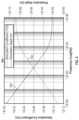
- FIG. 1is a plot depicting frequency-dependent electric permittivity of ice at a temperature of zero degrees Celsius.
- FIG. 2is a plot depicting frequency-dependent electric permittivity of liquid-phase water at a temperature of zero degrees Celsius.
- FIG. 3is a schematic depiction of dipoles within an ice crystalline structure.
- FIG. 4is a plot depicting frequency-dependent optical penetration and absorption in ice.
- FIG. 5is a schematic diagram of an illustrative ice processing device, in accordance with aspects of the present teachings.
- FIG. 6is a front view of the ice processing device of FIG. 5 .
- FIG. 7is a schematic diagram of an illustrative system for controlling ice crystallization, in accordance with aspects of the present teachings.
- FIG. 8is a schematic diagram of an object in which large ice crystals are formed.
- FIG. 9is a schematic diagram of an object in which smaller ice crystals are formed.
- an ice processing systemconfigured to vary an electromagnetic field density at a temperature-dependent frequency, as well as related methods, are described below and illustrated in the associated drawings.
- an ice processing system in accordance with the present teachings, and/or its various componentsmay contain at least one of the structures, components, functionalities, and/or variations described, illustrated, and/or incorporated herein.
- the process steps, structures, components, functionalities, and/or variations described, illustrated, and/or incorporated herein in connection with the present teachingsmay be included in other similar devices and methods, including being interchangeable between disclosed embodiments.
- the following description of various examplesis merely illustrative in nature and is in no way intended to limit the disclosure, its application, or uses. Additionally, the advantages provided by the examples and embodiments described below are illustrative in nature and not all examples and embodiments provide the same advantages or the same degree of advantages.
- substantiallymeans to be more-or-less conforming to the particular dimension, range, shape, concept, or other aspect modified by the term, such that a feature or component need not conform exactly.
- a “substantially cylindrical” objectmeans that the object resembles a cylinder, but may have one or more deviations from a true cylinder.
- Processing logicmeans any suitable device(s) or hardware configured to process data by performing one or more logical and/or arithmetic operations (e.g., executing coded instructions).
- processing logicmay include one or more processors (e.g., central processing units (CPUs) and/or graphics processing units (GPUs)), microprocessors, clusters of processing cores, FPGAs (field-programmable gate arrays), artificial intelligence (AI) accelerators, digital signal processors (DSPs), and/or any other suitable combination of logic hardware.
- processorse.g., central processing units (CPUs) and/or graphics processing units (GPUs)
- microprocessorse.g., microprocessors, clusters of processing cores, FPGAs (field-programmable gate arrays), artificial intelligence (AI) accelerators, digital signal processors (DSPs), and/or any other suitable combination of logic hardware.
- AIartificial intelligence
- DSPsdigital signal processors
- an ice processing systemin accordance with aspects of the present teachings includes one or more electrodes configured to create a time-varying electromagnetic field in a cavity, and a controller configured to oscillate a field density of the electromagnetic field (e.g., an intensity of the field in Volts per meter or other suitable units) at a frequency which depends on the temperature of an object in the cavity.
- the frequencyis selected based on a temperature of the object to establish and maintain a resonance condition of dipoles in ice crystals present in the object.
- Frequencies associated with resonance conditions of dipoles in ice crystalstypically differ significantly from frequencies associated with resonance conditions of dipoles in liquid-phase water. Accordingly, an electromagnetic field varied at the ice resonance frequency tends to selectively heat ice, substantially without heating liquid-phase water.
- the selective heating effectis enabled by dielectric material properties of ice and liquid-phase water, described in the following paragraphs.
- the dielectric response of an object to an electromagnetic fieldmay be characterized, in at least some aspects, by the object's permittivity, a generally complex parameter relating to behavior of electric charges within the object in the presence of the applied electromagnetic field.
- FIG. 1is a plot depicting the frequency dependence of real permittivity component 105 and imaginary permittivity component 110 of ice at a temperature of zero degrees Celsius (0° C.).
- imaginary permittivity component 110 of icehas a relatively high value or peak 125 corresponding to a particular frequency. This frequency is associated with a resonance of dipoles in the ice, which may include intrinsic dipoles of water, dipoles related to free ions, and/or any other suitable dipoles.
- FIG. 3depicts dipoles 130 of water molecules (e.g., H 2 O molecules) within an illustrative ice crystalline lattice.
- the response of dipoles 130 to an applied electromagnetic fieldis typically associated with movement of lattice defects and is therefore temperature-dependent.
- a hexagonal crystalline latticeis depicted in FIG. 3 , but other ice crystalline structures (e.g., cubic lattices) are also possible.
- FIG. 1illustrates the permittivity of ice at a particular temperature (zero degrees Celsius).
- the frequency associated with dipole resonancee.g., with a high absorption
- FIG. 1Other features of the frequency dependence of the real and imaginary permittivity components may also differ.
- FIG. 2depicts real permittivity component 135 and imaginary permittivity component 140 of liquid-phase water at zero degrees Celsius.
- Imaginary permittivity component 140 of liquid-phase waterhas a peak 145 associated with a resonance frequency of dipoles in the liquid-phase water. Accordingly, liquid-phase water absorbs energy from (e.g., is heated by) electromagnetic fields oscillating at the resonance frequency associated with peak 145 more readily than from electromagnetic fields oscillating at other frequencies.
- the resonance frequency associated with energy absorption by liquid-phase water(corresponding to peak 145 ) is far from the resonance frequency associated with energy absorption by ice (corresponding to peak 125 ).
- imaginary permittivity component 140 of liquid-phase wateris very low at frequencies near ice absorption peak 125 . Accordingly, an electromagnetic field oscillating at the resonance frequency of ice (the frequency corresponding to peak 125 ) typically is absorbed very weakly or not at all by liquid-phase water. An electromagnetic field oscillating at frequencies equal or nearly equal to the resonance frequency of ice therefore tends to heat ice without heating liquid-phase water.
- FIG. 4is a plot depicting the frequency dependence of an optical absorption coefficient 150 and an optical penetration depth 160 of ice, according to an illustrative model based on the Beer-Lambert law. As FIG. 4 shows, the predicted optical penetration is deep over a broad range of frequencies. Accordingly, an applied electromagnetic field typically penetrates deeply enough into a volume of ice to selectively heat interior portions of the volume as well as portions near the surface.
- systems and methods of the present disclosureare configured to selectively heat ice by the application of an electromagnetic field (also referred to as a pulsed electric field, or PEF) having a density oscillating at an appropriate temperature-dependent frequency.
- an electromagnetic fieldalso referred to as a pulsed electric field, or PEF
- PEFpulsed electric field
- systems and methodsare described herein in the context of processing food products, they may be used in any suitable context wherein selective heating of ice is desired.
- systems and methods of the present disclosuremay be used to melt ice and/or inhibit the formation of ice on surfaces such as evaporator coils, aircraft wings or other components, streets, driveways, sidewalks, rooftops, or any other suitable surfaces.
- Ice processing device 200is an example of an ice processing system configured to selectively heat ice, as described above.
- FIG. 5is a schematic depiction of ice processing device 200 .
- Ice processing device 200includes an enclosure 210 defining a cavity 212 .
- Enclosure 210may comprise any suitable size and shape for containing at least one object 220 .
- enclosure 210may have a rectangular shape, a cylindrical shape, and/or any other suitable shape.
- Cavity 212 defined by enclosure 210may have substantially the same shape as the enclosure, or may have a different shape.
- enclosure 210comprises, or is part of, a conventional freezer, a dedicated freezer compartment, or an adjustable temperature compartment.
- Object 220may comprise any object suitable for processing according to aspects of the present teachings (e.g., to be exposed to an electromagnetic field having an appropriate temperature-dependent frequency).
- object 220comprises material that has ice crystals and/or is susceptible to the formation of ice crystals.
- object 220comprises a food product, but in some examples the object may comprise another type of object (e.g., material not intended for consumption).
- object 220comprises a volume of air or other fluid. Alternatively, or additionally, object 220 may comprise vacuum.
- Ice processing device 200further includes one or more electrodes 225 configured to create a time-varying electromagnetic field within cavity 212 .
- Electrodes 225may be disposed in any suitable configuration proximate the cavity. In the example depicted in FIG. 5 , electrodes 225 comprise a first electrode plate 227 and a second electrode plate 229 disposed on opposing lateral sides of cavity 212 . However, other electrode configurations are possible. For example, one electrode may be disposed on a top side of the cavity and one electrode may be disposed on a bottom side of the cavity. As another example, one electrode may be disposed at a central portion of the cavity, and a pair of electrodes may be disposed on opposing sides of the cavity (e.g., top and bottom, or lateral sides).
- the cavitycomprises a drawer, and one electrode is disposed above the drawer and another electrode is disposed below the drawer. Some examples include more than two electrodes, and some examples include a single electrode (e.g., an antenna).
- electrodes 225are each designed to produce an electromagnetic field specific to the size and shape of cavity 212 .
- electrodes 225may be sized and shaped to produce an electromagnetic field that is substantially uniform in space across a predetermined region of cavity 212 . With a spatially uniform field, the ability of device 200 to selectively process ice within object 220 is independent of the exact position of the object within cavity 212 , which makes the device easier to use.
- Electrodes 225are configured to produce a time-varying electromagnetic field within cavity 212 (e.g., encompassing object 220 ).
- electrodes 225may be connected to a pulse generator 235 (e.g., a high-voltage pulse generator) configured to independently control an electric potential on each electrode (e.g., on first and second electrode plates 227 , 229 ) such that the desired electromagnetic field is created within cavity 212 .
- Pulse generator 235is connected to electrodes 225 by high-voltage wire(s) 237 and/or any other suitable connection.
- a power source 240(e.g., an AC/DC power supply, a DC power supply, and/or any other suitable source) is configured to provide power to pulse generator 235 and/or to any other suitable components of ice processing device 200 .
- Ice processing device 200may further include a ground plane 242 and/or any other suitable electrical components.
- electrodes 225are configured to produce a respective electromagnetic field in each of two or more regions of cavity 212 .
- the frequency and/or amplitude of the field within each regionmay be independently controllable (e.g., based on temperature data associated with the corresponding region). In this manner, objects having different temperatures, and/or objects having temperatures changing at different rates (e.g., due to different compositions and/or sizes), may be placed in different regions and efficiently processed simultaneously.
- the electromagnetic fields associated with the different regionsmay be generated by a common set of electrodes or by different sets of electrodes dedicated to each region.
- the temporal variation of the electromagnetic field(s) in cavity 212may comprise a sinusoidal waveform, a square waveform, a triangular and/or sawtooth waveform, any suitable combination of the foregoing, and/or any other suitable waveform.
- the waveformmay comprise substantially a single frequency, multiple discrete frequencies, a broad frequency band, and/or any other suitable spectrum. For convenience, however, a single frequency is referred to herein.
- Ice processing device 200further includes a temperature sensor 250 configured to measure temperature data corresponding to a temperature of object 220 within cavity 212 .
- Temperature sensor 250may comprise a thermistor, thermocouple, resistance temperature detector, semiconductor-based sensor, non-contact temperature probe (e.g., an infrared temperature sensor and/or the like), and/or any other suitable device. Temperature data measured by temperature sensor 250 may correspond to a surface temperature of object 220 , an interior temperature of object 220 , an average temperature of object 220 , and/or any other suitable temperature.
- Temperature sensor 250is coupled to a controller 255 configured to receive the temperature data from the temperature sensor and to oscillate a density of the electromagnetic field at a frequency which depends on the temperature of object 220 .
- controller 255is configured to vary the density of the electromagnetic field within cavity 212 at a temperature-dependent frequency suitable to establish and maintain a resonance condition of dipoles within ice crystals present within object 220 , such that energy from the electromagnetic field is readily absorbable by the ice crystals.
- the frequencyis selected based on temperature data received from the temperature sensor. Any suitable algorithm may be used to determine an appropriate frequency based on the temperature data.
- Controller 255may comprise any data processing system and/or processing logic suitable for controlling the electromagnetic field in this manner.
- Temperature datamay be obtained by temperature sensor 250 and received by controller 255 at any suitable rate, and the frequency of the electromagnetic field may be adjusted at any suitable rate.
- the field frequencyis selected based on an initial temperature measurement and is not adjusted based on temperature changes.
- the field frequencyis updated at suitable time intervals, which may be predetermined and/or based on measured temperature data (e.g., so that the frequency is updated more often when the temperature is changing rapidly).
- the frequencyis updated based on the measured temperature data substantially in real time, such that the dipole resonance condition is continuously maintained as the ice is heated.
- temperature sensor 250is omitted, and the temperature within the cavity is determined and/or estimated in another way. For example, the time during which a compressor of a refrigeration cycle is active may be measured and used to calculate temperature data.
- Controller 255is typically configured to increase the frequency of the electromagnetic field as the temperature of object 220 increases. In this manner, the electromagnetic field is maintained substantially at resonance with dipoles in any ice crystals present in object 220 as the temperature of the object increases. In some examples, controller 255 increases the frequency of the electromagnetic field with increasing temperature within a range of 100 Hz to 100 kHz. For example, the frequency may be changed within a range of 1 kHz to 10 kHz when the temperature of the object changes within a range of ⁇ 30 degrees Celsius to 0 degrees Celsius. Within these frequency ranges, the electromagnetic field substantially maintains a resonance with ice crystal dipoles within object 220 , such that the ice crystals absorb energy from the field relatively strongly even as the temperature of the object (e.g., of the ice) changes.
- controller 255may be configured to adjust a maximum amplitude of the electromagnetic field density based on temperature data received from temperature sensor 250 .
- controller 255may be configured to cause a maximum amplitude of the electromagnetic field density to change as the temperature sensed by temperature sensor 250 increases or decreases.
- the maximum amplitudemay be decreased as the temperature increases (e.g., as the temperature increases toward 0 degrees Celsius). This may help to avoid overheating.
- decreasing the amplitude as the temperature increasesmay help to increase the temperature of object 220 at a constant rate, because less energy is required to raise the temperature of the object as the temperature of the object increases.
- the maximum amplitudemay be increased as the temperature increases (e.g., to maintain a rate of heating as the absorption peak shifts, especially if the field frequency is not also adjusted).
- the maximum field amplitudemay be increased as the temperature is decreased, because more energy is typically required to maintain a supercooling effect.
- the electromagnetic field intensitymay be changed in any suitable manner based on the temperature data, the field frequency, and/or any other suitable parameter.
- the maximum amplitude of the electromagnetic field densityfalls within a range of 100 V/m (Volts per meter) to 100,000 V/m, 100 V/m to 10,000 V/m, 1000 V/m to 10,000 V/m, 1000 V/m to 100,000 V/m, and/or any other suitable range.
- Controller 255may be coupled directly or indirectly to one or more of electrodes 225 in any suitable manner enabling the controller to control the frequency (and optionally, amplitude) of the electromagnetic field generated by the electrodes.
- controller 255is coupled to pulse generator 235 , which is in turn coupled to first and second electrode plates 227 , 229 .
- controller 255may be coupled directly to one or more electrodes.
- controller 255may be part of pulse generator 235 (e.g., the pulse generator may be configured to receive temperature data from temperature sensor 250 and to adjust the frequency of the generated electromagnetic field accordingly).
- Ice processing device 200may further include one or more features to increase user safety.
- an access sensor 270may be provided to detect access to cavity 212 and, in response, to stop production of the electromagnetic field within the cavity (e.g., via controller 255 ).
- access sensor 270may detect that a door of enclosure 210 has opened, that a new object is present within cavity 212 , that object 220 and/or another object is positioned too near an electrode 225 , and/or any other suitable indication.
- the electromagnetic field within cavity 212is turned off (e.g., by discharging electrodes 225 , breaking an electrical circuit associated with the electrodes, and/or any other suitable method).
- controller 255may be coupled to access sensor 270 and configured to deactivate the field in response to detection of access.
- Ice processing device 200may further include a status indicator 275 configured to indicate that the device is active (e.g., that electrodes 225 are producing an electromagnetic field within cavity 212 ).
- status indicator 275may comprise one or more lights, LEDs, LCDs, audible alerts, and/or any other suitable indicator(s).
- Status indicator 275informs users that electrodes 225 are energized and that accessing cavity 212 may lead to electrical shock and/or other hazards.
- one or more electrode coversmay be configured to electrically isolate electrodes 225 .
- the electrode coversmay physically obstruct (e.g., block access to) electrodes 225 , thereby preventing a user or object from contacting the electrodes.
- FIG. 6depicts a pair of illustrative electrode covers 280 disposed in front of first and second electrode plates 227 , 229 .
- electrode covers 280each comprise a plate of electrically insulating material having a plurality of holes.
- the electrode coversmay take other forms.
- the electrode coverseach comprise a coating directly applied to the electrode surfaces.
- System 300is an example of an ice processing system configured to selectively heat ice, as described above.
- System 300may be substantially similar to ice processing device 200 in at least some respects.
- system 300includes a plurality of electrodes 305 .
- Electrodes 305are configured to generate electromagnetic fields within a cavity 310 .
- Cavity 310may be any suitable region of space within which electrodes 305 generate an electromagnetic field.
- cavity 310is defined by one or more surfaces (e.g., cavity walls), an enclosure, and/or any other suitable structure. Additionally, or alternatively, cavity 310 may be defined by electrodes 305 .
- An object 315is disposed within cavity 310 to be exposed to the electromagnetic field.
- Electrodes 305which may be similar to electrodes 225 of device 200 , may comprise any shape suitable for generating an appropriate electromagnetic field in cavity 310 .
- the plurality of electrodes 305may include a pair of electrode plates disposed on opposite lateral sides of cavity 310 .
- electrodes 305may be elongate and/or have any other suitable shape(s). The electrodes do not necessarily all have the same shape and/or size. In some examples, only one electrode is included.
- System 300further includes a state control 320 configured to control electric potential of electrodes 305 and thereby to cause a density of the electromagnetic field within cavity 310 to vary at a selected frequency.
- the electric potential of each electrode 305is independently controllable by state control 320 .
- System 300includes a temperature sensor 325 is configured to measure temperature data corresponding to a temperature of object 315 .
- Temperature sensor 325may be substantially similar to temperature sensor 250 of device 200 in at least some respects. Accordingly, temperature sensor 325 may comprise an infrared sensor, a thermocouple, and/or any other suitable temperature-sensing device(s), and may measure a surface temperature of object 315 , an interior temperature of object 315 , an average temperature of object 315 , and/or any other temperature data suitable for determining an appropriate frequency.
- the selected frequencyis in the range of 100 Hz to 100 kHz, which encompasses dipole resonance conditions of ice crystals within food products under a suitable range of conditions.
- State control 320may control the electric potential of electrodes 305 to vary generate an electromagnetic field having a temperature-dependent frequency at least partially automatically.
- state control 320may be configured to receive temperature data from temperature sensor 325 and to determine an appropriate frequency based on the temperature data according to any suitable algorithm. Alternatively, or additionally, a frequency may be selected manually by a user based on the temperature data.
- state control 320is configured to vary the electromagnetic field density at a frequency chosen to maintain a resonance condition of ice crystals forming in object 315 . Varying the electromagnetic field frequency in a manner that maintains a resonance condition of the ice crystals enables the ice crystals to absorb energy from the field relatively efficiently as the ice temperature changes. In some examples, state control 320 is configured to increase the frequency of the field as a function of increasing temperature of object 315 , and to increase or decrease an amplitude of the electromagnetic field density as a function of increasing temperature of the object.
- System 300may be configured to control ice crystallization within object 315 .
- the frequency of the electromagnetic fieldis chosen to inhibit formation of ice crystals in liquid water (e.g., liquid-phase water within object 315 ) as the temperature of the object decreases below 0 degrees Celsius (e.g., a freezing point of water).
- the frequencymay be selected based on temperature such that the resonance condition is met as ice starts (e.g., nucleation centers) begin to form. Accordingly, the ice starts are heated and tend to be melted before ice crystals can form. Inhibiting formation of ice crystals in liquid-phase water as the temperature of the water decreases below its freezing point may be referred to as supercooling the water.
- the ice startsmay be heated continuously or non-continuously (e.g., periodically or irregularly) by varying the time during which the electromagnetic field is present in cavity 310 .
- the frequency of the electromagnetic fieldmay be chosen to reduce a characteristic size of ice crystals forming in object 315 , as the temperature of the object decreases below a freezing point of the object.
- the frequency of the electromagnetic fieldmay tend to heat these ice starts, thereby melting them.
- ice starts having a size below a critical diametertend to be less susceptible to heating by the electromagnetic field. Accordingly, the electromagnetic field may preferentially remove large ice starts while allowing smaller ice starts to form.
- FIGS. 8 - 9schematically depict object 315 after the formation of ice crystals of different sizes and concentrations. Specifically, FIG. 8 depicts object 315 having a plurality of large ice crystals 330 , and FIG. 9 depicts object 315 having a plurality of smaller ice crystals 335 that are reduced in size relative to crystals 330 .
- the rectilinear shapes of crystals 330 and 335is purely symbolic—the actual ice crystals may form in a wide variety of crystalline shapes.
- the electric potential of electrodes 305may be increased as the temperature of object 315 decreases below a freezing point of the object (e.g., the electromagnetic field amplitude is increased as the temperature decreases below freezing). This tends to maintain liquid-phase water within object 315 in a super-cooled state, inhibiting the formation of ice crystals in the liquid-phase water and leading to a reduced size of any ice crystals that do form within the object.
- An ice processing devicecomprising an enclosure defining a cavity; a temperature sensor configured to measure temperature data corresponding to a temperature within the cavity; a plurality of electrodes configured to create an electromagnetic field within the cavity; and a controller configured to receive the temperature data from the temperature sensor and to oscillate a density of the electromagnetic field at a frequency which depends on the temperature.
- a system for controlling ice crystallizationcomprising a plurality of electrodes configured to generate electromagnetic fields within a cavity; a temperature sensor configured to measure temperature data corresponding to a temperature of an object disposed within the cavity; and a state control configured to control electric potential of the electrodes and thereby to cause a density of the electromagnetic field within the cavity to vary at a temperature-dependent frequency in a range of 100 Hz to 100 kHz.
- a temperature controlling systemcomprising an enclosure defining a cavity; means for measuring a temperature of an object disposed in the cavity; means for creating an electromagnetic field within the cavity; and means for varying a density of the electromagnetic field within the cavity at a temperature-dependent frequency corresponding to a dipole resonance condition of ice crystals within the object.
- means for creating the electromagnetic fieldinclude a pair of electrode plates disposed proximate the enclosure, wherein an electric potential associated with each electrode plate is independently controllable.
- means for measuring the temperature of the objectincludes a temperature sensor (e.g., an infrared sensor).
- a temperature sensore.g., an infrared sensor
- means for varying the density of the electromagnetic field within the cavityincludes means for varying the frequency within a range of 100 Hz to 100 kHz.
- means for varying the density of the electromagnetic field within the cavityincludes means for varying an amplitude of the electromagnetic field density within a range of 100 V/m to 10,000 V/m.
- a method of inhibiting ice formation on an evaporator coilcomprising exposing the evaporator coil to an electromagnetic field having a temperature-dependent frequency corresponding to a dipole resonance condition of ice crystals forming on the evaporator coil.
- a systemconfigured to generate an electrical current in an evaporator coil, wherein the current oscillates at a frequency corresponding to a greater conductivity in ice than in liquid-phase water, thereby inhibiting ice formation on the evaporator coil.
- a method of releasing ice from an ice makercomprising exposing ice contacting a surface of the ice maker to an electromagnetic field having a temperature-dependent frequency corresponding to a resonance condition of dipoles within the ice, thereby causing the ice to melt and detach from the surface.
- a method of producing snowcomprising generating an electromagnetic field having a temperature-dependent frequency within a volume of humid air, thereby cooling the air below the freezing point of water while inhibiting formation of ice within the air; and then removing the electromagnetic field.
- a systemcomprising any feature described herein, either individually or in combination with any other such feature, configured to inhibit formation of ice on selected portions of a surface or volume and to apply liquid water to the entire surface or volume, such that ice is selectively formed on portions of the surface or volume where ice formation is not inhibited.
- This systemmay be referred to as an “ice printer.”
- a method of detecting icecomprising exposing an object to an electromagnetic field; measuring a phase change of the field; and determining, based on the phase change, information associated with the presence of ice within the object.
- the electromagnetic fieldmay comprise a plurality of pulses having frequencies below, at, or above a resonance frequency of ice.
- the information determinedmay comprise a fraction of ice in the object, the presence of ice on a surface of the object, and/or any other suitable data.
- a systemconfigured to generate an electrical current in a frozen food product, wherein the current oscillates at a frequency corresponding to a greater conductivity in ice than in liquid-phase water, thereby selectively heating ice within the frozen food product.
- illustrative embodiments and examples described hereinallow for selectively heating ice (e.g., substantially without heating liquid-phase water).
- illustrative embodiments and examples described hereinallow for heating ice without direct contact with a heat source.
- illustrative embodiments and examples described hereinallow for reducing a size of ice crystals forming within an object.
- the reduced size of the ice crystalsreduces potential adverse effects of the freezing process (e.g., drip loss, cellular damage, and/or the like) on food texture, taste, and nutritional value.
- illustrative embodiments and examples described hereinallow a frozen food product to be thawed substantially without heating water within the food product, thereby avoiding cooking portions of the food product during the thawing process.
- illustrative embodiments and examples described hereinallow processing of ice within a food product or other object (e.g., to inhibit crystal formation, promote growth of small crystals, etc.) without adding any additives configured to lower the freezing point of the object.
- illustrative embodiments and examples described hereininvolve application of electromagnetic fields having a frequency near a resonance frequency of ice, which may heat the ice efficiently and/or optimally.
- known systems involving electromagnetic fieldstypically apply static fields or fields having a frequency far from the resonance frequency of ice.
- many systemsutilize fields oscillating at or near standard power delivery frequencies (e.g., 40 Hz to 60 Hz), well below the ice resonance frequency. Ice absorbs energy much less readily from fields far from resonance than from fields near resonance. Accordingly, known systems heat ice inefficiently compared to the systems and methods disclosed herein.
- illustrative embodiments and examples described hereinproduce high quality frozen food products without use of a blast chiller, thereby avoiding the high cost of purchasing and operating the blast chiller.
Landscapes
- Engineering & Computer Science (AREA)
- Physics & Mathematics (AREA)
- Chemical & Material Sciences (AREA)
- Life Sciences & Earth Sciences (AREA)
- General Engineering & Computer Science (AREA)
- Thermal Sciences (AREA)
- Mechanical Engineering (AREA)
- Combustion & Propulsion (AREA)
- Zoology (AREA)
- Polymers & Plastics (AREA)
- Food Science & Technology (AREA)
- Wood Science & Technology (AREA)
- Electromagnetism (AREA)
- Production, Working, Storing, Or Distribution Of Ice (AREA)
- Freezing, Cooling And Drying Of Foods (AREA)
Abstract
Description
Claims (17)
Priority Applications (1)
| Application Number | Priority Date | Filing Date | Title |
|---|---|---|---|
| US16/383,703US11576408B2 (en) | 2019-04-15 | 2019-04-15 | Ice processing system |
Applications Claiming Priority (1)
| Application Number | Priority Date | Filing Date | Title |
|---|---|---|---|
| US16/383,703US11576408B2 (en) | 2019-04-15 | 2019-04-15 | Ice processing system |
Publications (2)
| Publication Number | Publication Date |
|---|---|
| US20200323246A1 US20200323246A1 (en) | 2020-10-15 |
| US11576408B2true US11576408B2 (en) | 2023-02-14 |
Family
ID=72748395
Family Applications (1)
| Application Number | Title | Priority Date | Filing Date |
|---|---|---|---|
| US16/383,703Active2040-01-08US11576408B2 (en) | 2019-04-15 | 2019-04-15 | Ice processing system |
Country Status (1)
| Country | Link |
|---|---|
| US (1) | US11576408B2 (en) |
Cited By (1)
| Publication number | Priority date | Publication date | Assignee | Title |
|---|---|---|---|---|
| US20230348073A1 (en)* | 2022-04-28 | 2023-11-02 | Rohr, Inc. | Ice protection system including frequency dependent susceptor |
Families Citing this family (6)
| Publication number | Priority date | Publication date | Assignee | Title |
|---|---|---|---|---|
| DE102020203521A1 (en)* | 2020-03-19 | 2021-09-23 | BSH Hausgeräte GmbH | PEF cooking device and method of setting up the same |
| CN114688799B (en)* | 2020-12-31 | 2023-03-17 | 青岛海尔电冰箱有限公司 | Refrigerators with freezer storage components |
| US11747071B2 (en) | 2021-10-07 | 2023-09-05 | Haier Us Appliance Solutions, Inc. | Systems and methods for detecting and monitoring ice formation within an ice maker |
| US20240032551A1 (en)* | 2022-07-28 | 2024-02-01 | Xerox Corporation | Feedback-based device for nucleation control |
| US12433299B2 (en) | 2022-07-28 | 2025-10-07 | Xerox Corporation | System and method for metamaterial array-based field-shaping |
| US12392535B2 (en) | 2022-07-28 | 2025-08-19 | Xerox Corporation | System and method for controlling crystallized forms of water |
Citations (53)
| Publication number | Priority date | Publication date | Assignee | Title |
|---|---|---|---|---|
| US4210795A (en)* | 1978-11-30 | 1980-07-01 | Litton Systems, Inc. | System and method for regulating power output in a microwave oven |
| US4303820A (en) | 1979-12-31 | 1981-12-01 | General Electric Company | Capacitative apparatus for thawing frozen food in a refrigeration appliance |
| US4524079A (en)* | 1983-11-10 | 1985-06-18 | Maxwell Laboratories, Inc. | Deactivation of microorganisms by an oscillating magnetic field |
| US5084377A (en) | 1984-09-19 | 1992-01-28 | Larry Rowan | Cryogenic suspension method |
| US5521360A (en)* | 1994-09-14 | 1996-05-28 | Martin Marietta Energy Systems, Inc. | Apparatus and method for microwave processing of materials |
| US5690978A (en) | 1996-09-30 | 1997-11-25 | Ohio State University | High voltage pulsed electric field treatment chambers for the preservation of liquid food products |
| US5776529A (en) | 1994-12-23 | 1998-07-07 | Washington State University Research Foundation | Continuous flow electrical treatment of flowable food products |
| US5873254A (en)* | 1996-09-06 | 1999-02-23 | Interface Multigrad Technology | Device and methods for multigradient directional cooling and warming of biological samples |
| US6027075A (en)* | 1997-06-16 | 2000-02-22 | Trustees Of Dartmouth College | Systems and methods for modifying ice adhesion strength |
| US6138555A (en) | 1998-09-18 | 2000-10-31 | Kowa Business Planning Of America, Ltd. | Food processing device and electric system for the processing device, and high voltage-weak pulse electric current impresser for food |
| US6239601B1 (en)* | 1996-03-20 | 2001-05-29 | The United States Of America As Represented By The Administrator Of The National Aeronautics And Space Administration | Thickness measurement device for ice, or ice mixed with water or other liquid |
| US6250087B1 (en) | 1999-10-01 | 2001-06-26 | Abi Limited | Super-quick freezing method and apparatus therefor |
| US6281801B1 (en)* | 1997-06-04 | 2001-08-28 | Bechtel Bwxt Idaho, Llc | System and method for monitoring water content or other dielectric influences in a medium |
| US20010017082A1 (en)* | 2000-02-02 | 2001-08-30 | Stork Food & Dairy Systems B.V. | Treatment apparatus and method for preserving pumpable food products in a pulsed electric field |
| US6451364B1 (en) | 1997-03-17 | 2002-09-17 | Akinori Ito | Method of treating a food object in an electrostatic field |
| US20020175163A1 (en)* | 1998-12-17 | 2002-11-28 | Personal Chemistry I Uppsala Ab | Microwave apparatus and methods of performing chemical reactions |
| US6684647B2 (en)* | 1998-06-15 | 2004-02-03 | The Trustees Of Dartmouth College | High-frequency melting of ice between freezer packages |
| US20040053204A1 (en)* | 2000-06-07 | 2004-03-18 | Morris George J. | Methods and apparatus for freezing tissue |
| US6733434B2 (en)* | 1997-12-08 | 2004-05-11 | Jerry I. Jacobson | Method and apparatus for electromagnetically restructuring ingestible substances for organismic consumption |
| US6847024B2 (en)* | 1998-06-15 | 2005-01-25 | Trustees Of Dartmouth College | Prevention of ice formation by applying electric power to a liquid water layer |
| US7087876B2 (en)* | 1998-06-15 | 2006-08-08 | The Trustees Of Dartmouth College | High-frequency melting of interfacial ice |
| WO2006121397A1 (en) | 2005-05-12 | 2006-11-16 | Kraft Foods R & D Inc. | Root vegetable treatment |
| US20090199577A1 (en)* | 2005-03-31 | 2009-08-13 | Norio Owada | Quick Freezing Apparatus and Quick Freezing Method |
| US20090236335A1 (en)* | 2006-02-21 | 2009-09-24 | Rf Dynamics Ltd. | Food preparation |
| US7629558B2 (en)* | 2002-02-11 | 2009-12-08 | The Trustees Of Dartmouth College | Systems and methods for modifying an ice-to-object interface |
| US7819003B2 (en)* | 2002-06-11 | 2010-10-26 | Intelligent Technologies International, Inc. | Remote monitoring of fluid storage tanks |
| US7883609B2 (en)* | 1998-06-15 | 2011-02-08 | The Trustees Of Dartmouth College | Ice modification removal and prevention |
| US7994962B1 (en)* | 2007-07-17 | 2011-08-09 | Drosera Ltd. | Apparatus and method for concentrating electromagnetic energy on a remotely-located object |
| WO2011139144A1 (en) | 2010-05-05 | 2011-11-10 | Ixl Nederland B/V. | Method and system for treating a substantially solid food product |
| US8106539B2 (en)* | 2008-09-27 | 2012-01-31 | Witricity Corporation | Wireless energy transfer for refrigerator application |
| US20120103972A1 (en)* | 2009-09-29 | 2012-05-03 | Toshiyuki Okajima | High-frequency heating device and high-frequency heating method |
| US20120153733A1 (en)* | 2008-09-27 | 2012-06-21 | Schatz David A | Wireless energy transfer systems |
| US20120308694A1 (en)* | 2011-06-03 | 2012-12-06 | Price William D | Apparatus and methodology for even defrosting of frozen food products |
| US20120312801A1 (en)* | 2009-11-10 | 2012-12-13 | Goji, Ltd. | Device and method for heating using rf energy |
| US8389916B2 (en)* | 2007-05-21 | 2013-03-05 | Goji Limited | Electromagnetic heating |
| US8555778B2 (en) | 2010-05-25 | 2013-10-15 | Minato Ichinose | Freshness prolonging device for foodstuff |
| US20130273222A1 (en)* | 2012-04-16 | 2013-10-17 | Eugenio Minvielle | Preservation System for Nutritional Substances |
| US8759729B2 (en)* | 2006-02-21 | 2014-06-24 | Goji Limited | Electromagnetic heating according to an efficiency of energy transfer |
| US8849441B2 (en)* | 2008-10-31 | 2014-09-30 | The Invention Science Fund I, Llc | Systems, devices, and methods for making or administering frozen particles |
| US8899069B2 (en) | 2003-08-11 | 2014-12-02 | Yugengaisha Sun World Kawamura | Food preserving method and its device |
| US20150147778A1 (en)* | 2012-04-04 | 2015-05-28 | National University Of Singapore | Cryo-preparation systems and methods for near-instantaneous vitrification of biological samples |
| US9132408B2 (en)* | 2010-05-03 | 2015-09-15 | Goji Limited | Loss profile analysis |
| US20150285552A1 (en) | 2014-04-07 | 2015-10-08 | General Electric Company | Refrigerator appliance and a method for defrosting a food item |
| US20160108484A1 (en)* | 2014-10-16 | 2016-04-21 | Glassy Metals, LLC | Method and apparatus for supercooling of metal/alloy melts and for the formation of amorphous metals therefrom |
| US9565869B2 (en) | 2014-07-14 | 2017-02-14 | Ixl Netherlands B.V. | Low field strength PEF cooking process and system |
| US20170055769A1 (en)* | 2015-09-01 | 2017-03-02 | Illinois Tool Works, Inc. | Multi-functional rf capacitive heating food preparation device |
| US9609889B2 (en) | 2010-05-10 | 2017-04-04 | Boston Com., Ltd. | Refrigerator and container for cold storage |
| US20170336133A1 (en) | 2016-05-19 | 2017-11-23 | Bsh Home Appliances Corporation | Cooking within a refrigeration cavity |
| US10126035B2 (en) | 2013-03-14 | 2018-11-13 | Whirlpool Corporation | Ice maker with heatless ice removal and method for heatless removal of ice |
| US20190142037A1 (en)* | 2017-11-16 | 2019-05-16 | The Bowden Group | System and methods for supercooling perishable products |
| US20190225521A1 (en)* | 2018-01-24 | 2019-07-25 | Stephan HEATH | Systems, apparatus, and/or methods for providing liquid treatment comprising at least one of disinfection, filtration and/or purification |
| US20190274196A1 (en)* | 2018-03-02 | 2019-09-05 | Whirlpool Corporation | System and method for zone cooking according to spectromodal theory in an electromagnetic cooking device |
| US20210381755A1 (en) | 2018-10-23 | 2021-12-09 | Panasonic Intellectual Property Management Co., Ltd. | Heating device and refrigerator equipped with heating device |
- 2019
- 2019-04-15USUS16/383,703patent/US11576408B2/enactiveActive
Patent Citations (79)
| Publication number | Priority date | Publication date | Assignee | Title |
|---|---|---|---|---|
| US4210795A (en)* | 1978-11-30 | 1980-07-01 | Litton Systems, Inc. | System and method for regulating power output in a microwave oven |
| US4303820A (en) | 1979-12-31 | 1981-12-01 | General Electric Company | Capacitative apparatus for thawing frozen food in a refrigeration appliance |
| US4524079A (en)* | 1983-11-10 | 1985-06-18 | Maxwell Laboratories, Inc. | Deactivation of microorganisms by an oscillating magnetic field |
| US5084377A (en) | 1984-09-19 | 1992-01-28 | Larry Rowan | Cryogenic suspension method |
| US5521360A (en)* | 1994-09-14 | 1996-05-28 | Martin Marietta Energy Systems, Inc. | Apparatus and method for microwave processing of materials |
| US5776529A (en) | 1994-12-23 | 1998-07-07 | Washington State University Research Foundation | Continuous flow electrical treatment of flowable food products |
| US6239601B1 (en)* | 1996-03-20 | 2001-05-29 | The United States Of America As Represented By The Administrator Of The National Aeronautics And Space Administration | Thickness measurement device for ice, or ice mixed with water or other liquid |
| US5873254A (en)* | 1996-09-06 | 1999-02-23 | Interface Multigrad Technology | Device and methods for multigradient directional cooling and warming of biological samples |
| US5690978A (en) | 1996-09-30 | 1997-11-25 | Ohio State University | High voltage pulsed electric field treatment chambers for the preservation of liquid food products |
| US6451364B1 (en) | 1997-03-17 | 2002-09-17 | Akinori Ito | Method of treating a food object in an electrostatic field |
| US20030068414A1 (en) | 1997-03-17 | 2003-04-10 | Akinori Ito | Method and equipment for treating electrostatic field and electrode used therein |
| US6281801B1 (en)* | 1997-06-04 | 2001-08-28 | Bechtel Bwxt Idaho, Llc | System and method for monitoring water content or other dielectric influences in a medium |
| US6027075A (en)* | 1997-06-16 | 2000-02-22 | Trustees Of Dartmouth College | Systems and methods for modifying ice adhesion strength |
| US6733434B2 (en)* | 1997-12-08 | 2004-05-11 | Jerry I. Jacobson | Method and apparatus for electromagnetically restructuring ingestible substances for organismic consumption |
| US6847024B2 (en)* | 1998-06-15 | 2005-01-25 | Trustees Of Dartmouth College | Prevention of ice formation by applying electric power to a liquid water layer |
| US7227110B2 (en) | 1998-06-15 | 2007-06-05 | The Trustees Of Dartmouth College | Prevention of ice formation by applying electric power to a liquid water layer |
| US7883609B2 (en)* | 1998-06-15 | 2011-02-08 | The Trustees Of Dartmouth College | Ice modification removal and prevention |
| US7087876B2 (en)* | 1998-06-15 | 2006-08-08 | The Trustees Of Dartmouth College | High-frequency melting of interfacial ice |
| US6684647B2 (en)* | 1998-06-15 | 2004-02-03 | The Trustees Of Dartmouth College | High-frequency melting of ice between freezer packages |
| US6138555A (en) | 1998-09-18 | 2000-10-31 | Kowa Business Planning Of America, Ltd. | Food processing device and electric system for the processing device, and high voltage-weak pulse electric current impresser for food |
| US20020175163A1 (en)* | 1998-12-17 | 2002-11-28 | Personal Chemistry I Uppsala Ab | Microwave apparatus and methods of performing chemical reactions |
| US6250087B1 (en) | 1999-10-01 | 2001-06-26 | Abi Limited | Super-quick freezing method and apparatus therefor |
| US20010017082A1 (en)* | 2000-02-02 | 2001-08-30 | Stork Food & Dairy Systems B.V. | Treatment apparatus and method for preserving pumpable food products in a pulsed electric field |
| US6393975B2 (en)* | 2000-02-02 | 2002-05-28 | Stork Food And Dairy Systems B.V. | Treatment apparatus and method for preserving pumpable food products in a pulsed electric field |
| US20040053204A1 (en)* | 2000-06-07 | 2004-03-18 | Morris George J. | Methods and apparatus for freezing tissue |
| US7629558B2 (en)* | 2002-02-11 | 2009-12-08 | The Trustees Of Dartmouth College | Systems and methods for modifying an ice-to-object interface |
| US7819003B2 (en)* | 2002-06-11 | 2010-10-26 | Intelligent Technologies International, Inc. | Remote monitoring of fluid storage tanks |
| US8899069B2 (en) | 2003-08-11 | 2014-12-02 | Yugengaisha Sun World Kawamura | Food preserving method and its device |
| US20090199577A1 (en)* | 2005-03-31 | 2009-08-13 | Norio Owada | Quick Freezing Apparatus and Quick Freezing Method |
| WO2006121397A1 (en) | 2005-05-12 | 2006-11-16 | Kraft Foods R & D Inc. | Root vegetable treatment |
| US9167633B2 (en)* | 2006-02-21 | 2015-10-20 | Goji Limited | Food preparation |
| US8759729B2 (en)* | 2006-02-21 | 2014-06-24 | Goji Limited | Electromagnetic heating according to an efficiency of energy transfer |
| US20110154836A1 (en)* | 2006-02-21 | 2011-06-30 | Eran Ben-Shmuel | Rf controlled freezing |
| US20150366006A1 (en)* | 2006-02-21 | 2015-12-17 | Goji Limited | Food preparation |
| US20210289594A1 (en)* | 2006-02-21 | 2021-09-16 | Goji Limited | Food preparation |
| US9872345B2 (en)* | 2006-02-21 | 2018-01-16 | Goji Limited | Food preparation |
| US20090236335A1 (en)* | 2006-02-21 | 2009-09-24 | Rf Dynamics Ltd. | Food preparation |
| US8653482B2 (en)* | 2006-02-21 | 2014-02-18 | Goji Limited | RF controlled freezing |
| US11057968B2 (en)* | 2006-02-21 | 2021-07-06 | Goji Limited | Food preparation |
| US20090236333A1 (en)* | 2006-02-21 | 2009-09-24 | Rf Dynamics Ltd. | Food preparation |
| US20110031236A1 (en)* | 2006-02-21 | 2011-02-10 | Rf Dynamics Ltd. | Food preparation |
| US20130056460A1 (en)* | 2006-02-21 | 2013-03-07 | Goji Ltd. | Food Preparation |
| US10080264B2 (en)* | 2006-02-21 | 2018-09-18 | Goji Limited | Food preparation |
| US10492247B2 (en)* | 2006-02-21 | 2019-11-26 | Goji Limited | Food preparation |
| US8389916B2 (en)* | 2007-05-21 | 2013-03-05 | Goji Limited | Electromagnetic heating |
| US20130119054A1 (en)* | 2007-05-21 | 2013-05-16 | Goji Ltd. | Electromagnetic heating |
| US7994962B1 (en)* | 2007-07-17 | 2011-08-09 | Drosera Ltd. | Apparatus and method for concentrating electromagnetic energy on a remotely-located object |
| US20120153733A1 (en)* | 2008-09-27 | 2012-06-21 | Schatz David A | Wireless energy transfer systems |
| US8106539B2 (en)* | 2008-09-27 | 2012-01-31 | Witricity Corporation | Wireless energy transfer for refrigerator application |
| US8849441B2 (en)* | 2008-10-31 | 2014-09-30 | The Invention Science Fund I, Llc | Systems, devices, and methods for making or administering frozen particles |
| US20120103972A1 (en)* | 2009-09-29 | 2012-05-03 | Toshiyuki Okajima | High-frequency heating device and high-frequency heating method |
| US20120312801A1 (en)* | 2009-11-10 | 2012-12-13 | Goji, Ltd. | Device and method for heating using rf energy |
| US9609692B2 (en)* | 2009-11-10 | 2017-03-28 | Goji Limited | Device and method for controlling energy |
| US9215756B2 (en)* | 2009-11-10 | 2015-12-15 | Goji Limited | Device and method for controlling energy |
| US20190364624A1 (en)* | 2009-11-10 | 2019-11-28 | Goji Limited | Device and method for heating using rf energy |
| US20170164431A1 (en)* | 2009-11-10 | 2017-06-08 | Goji Limited | Device and method for controlling energy |
| US9462635B2 (en)* | 2009-11-10 | 2016-10-04 | Goji Limited | Device and method for heating using RF energy |
| US20170027026A1 (en)* | 2009-11-10 | 2017-01-26 | Goji Limited | Device and method for heating using rf energy |
| US10405380B2 (en)* | 2009-11-10 | 2019-09-03 | Goji Limited | Device and method for heating using RF energy |
| US9807823B2 (en)* | 2010-05-03 | 2017-10-31 | Goji Limited | Loss profile analysis |
| US9132408B2 (en)* | 2010-05-03 | 2015-09-15 | Goji Limited | Loss profile analysis |
| WO2011139144A1 (en) | 2010-05-05 | 2011-11-10 | Ixl Nederland B/V. | Method and system for treating a substantially solid food product |
| US9609889B2 (en) | 2010-05-10 | 2017-04-04 | Boston Com., Ltd. | Refrigerator and container for cold storage |
| US8555778B2 (en) | 2010-05-25 | 2013-10-15 | Minato Ichinose | Freshness prolonging device for foodstuff |
| US20120308694A1 (en)* | 2011-06-03 | 2012-12-06 | Price William D | Apparatus and methodology for even defrosting of frozen food products |
| US20150147778A1 (en)* | 2012-04-04 | 2015-05-28 | National University Of Singapore | Cryo-preparation systems and methods for near-instantaneous vitrification of biological samples |
| US20130273222A1 (en)* | 2012-04-16 | 2013-10-17 | Eugenio Minvielle | Preservation System for Nutritional Substances |
| US10126035B2 (en) | 2013-03-14 | 2018-11-13 | Whirlpool Corporation | Ice maker with heatless ice removal and method for heatless removal of ice |
| US20150285552A1 (en) | 2014-04-07 | 2015-10-08 | General Electric Company | Refrigerator appliance and a method for defrosting a food item |
| US9565869B2 (en) | 2014-07-14 | 2017-02-14 | Ixl Netherlands B.V. | Low field strength PEF cooking process and system |
| US20160108484A1 (en)* | 2014-10-16 | 2016-04-21 | Glassy Metals, LLC | Method and apparatus for supercooling of metal/alloy melts and for the formation of amorphous metals therefrom |
| US20170055769A1 (en)* | 2015-09-01 | 2017-03-02 | Illinois Tool Works, Inc. | Multi-functional rf capacitive heating food preparation device |
| US10465976B2 (en) | 2016-05-19 | 2019-11-05 | Bsh Home Appliances Corporation | Cooking within a refrigeration cavity |
| US20170336133A1 (en) | 2016-05-19 | 2017-11-23 | Bsh Home Appliances Corporation | Cooking within a refrigeration cavity |
| US20190142037A1 (en)* | 2017-11-16 | 2019-05-16 | The Bowden Group | System and methods for supercooling perishable products |
| US20190225521A1 (en)* | 2018-01-24 | 2019-07-25 | Stephan HEATH | Systems, apparatus, and/or methods for providing liquid treatment comprising at least one of disinfection, filtration and/or purification |
| US20190274196A1 (en)* | 2018-03-02 | 2019-09-05 | Whirlpool Corporation | System and method for zone cooking according to spectromodal theory in an electromagnetic cooking device |
| US10772165B2 (en)* | 2018-03-02 | 2020-09-08 | Whirlpool Corporation | System and method for zone cooking according to spectromodal theory in an electromagnetic cooking device |
| US20210381755A1 (en) | 2018-10-23 | 2021-12-09 | Panasonic Intellectual Property Management Co., Ltd. | Heating device and refrigerator equipped with heating device |
Non-Patent Citations (6)
| Title |
|---|
| Aneas et al (Year: 2011).* |
| Aneas et al https://pdf.sciencedirectassets.com/271165/1-s2.0-S0963996911X00121/1-s2.0-S0963996911006491/main.pdf?X-Amz-Security-Token=IQoJb3JpZ2IuX2VjEJT%2F%2F%2F%2F%2F%2F%2F%2F%2F%2FwEaCXVzLWVhc3QtMSJHMEUCIQD76k%2BVAzkvVK3U58gB5pMKgiJV7gW4gUtUfRiRdAASsglgaJNgINTv7%2B4% 2BjmDgLv% (Year: 2011).* |
| Part 1 (Year: 2020).* |
| Part 2 (Year: 2020).* |
| Xanthakis et al (Year: 2014).* |
| Xanthakis et al https://www.sciencedirect.com/science/article/pii/S1466856414000708 (Year: 2014).* |
Cited By (2)
| Publication number | Priority date | Publication date | Assignee | Title |
|---|---|---|---|---|
| US20230348073A1 (en)* | 2022-04-28 | 2023-11-02 | Rohr, Inc. | Ice protection system including frequency dependent susceptor |
| US12037121B2 (en)* | 2022-04-28 | 2024-07-16 | Rohr, Inc. | Ice protection system including frequency dependent susceptor |
Also Published As
| Publication number | Publication date |
|---|---|
| US20200323246A1 (en) | 2020-10-15 |
Similar Documents
| Publication | Publication Date | Title |
|---|---|---|
| US11576408B2 (en) | Ice processing system | |
| Llave et al. | Dielectric properties of frozen tuna and analysis of defrosting using a radio-frequency system at low frequencies | |
| JP5281691B2 (en) | Storage device and storage method | |
| US20090044544A1 (en) | Refrigerator | |
| US20160128138A1 (en) | Method and device for processing frozen food | |
| EP1447632A1 (en) | Highly-efficient freezing apparatus and highly-efficient freezing method | |
| US20170181455A1 (en) | Apparatus and method for heating food products | |
| Zhang et al. | Freezing characteristics and relative permittivity of rice flour gel in pulsed electric field assisted freezing | |
| CN110671876B (en) | Supercooling freezing method, refrigerator and refrigerator control method | |
| JP3698776B2 (en) | refrigerator | |
| CN106387607A (en) | Unfreezing device and refrigerator | |
| CN102598851A (en) | Apparatus and method for heating using RF energy | |
| WO2000014522A1 (en) | Noncontact article temperature measuring device for food | |
| Li et al. | A strategy for improving the uniformity of radio frequency tempering for frozen beef with cuboid and step shapes | |
| RU2016132165A (en) | MEASURING DIELECTRIC PROPERTIES DURING THAWING OR FROZENING OF FOOD | |
| Zhou et al. | Performance comparison between the free running oscillator and 50 Ω radio frequency systems | |
| EP3174370A1 (en) | Multi-functional rf capacitive heating food preparation device | |
| EP1991820B1 (en) | Non-freezing refrigerator | |
| JP2005291525A (en) | Food freezing device and food thawing device | |
| CN107843063A (en) | Food freezing determination methods, refrigerator food preservation method and fresh-keeping refrigerator in refrigerator | |
| Kim et al. | Study of radio frequency thawing for cylindrical pork sirloin | |
| CN110730894A (en) | cooling device | |
| JP4926200B2 (en) | refrigerator | |
| JP2017161189A (en) | Freezing apparatus | |
| Erdogdu et al. | Innovative dielectric applications (microwave and radio frequency) for seafood thawing |
Legal Events
| Date | Code | Title | Description |
|---|---|---|---|
| AS | Assignment | Owner name:BSH HOME APPLIANCES CORPORATION, CALIFORNIA Free format text:ASSIGNMENT OF ASSIGNORS INTEREST;ASSIGNORS:JACOBS, CHRISTOPHER;TENNYSON, WESLEY;REEL/FRAME:048880/0423 Effective date:20190401 Owner name:BSH HAUSGERAETE GMBH, GERMANY Free format text:ASSIGNMENT OF ASSIGNORS INTEREST;ASSIGNORS:JACOBS, CHRISTOPHER;TENNYSON, WESLEY;REEL/FRAME:048880/0423 Effective date:20190401 | |
| FEPP | Fee payment procedure | Free format text:ENTITY STATUS SET TO UNDISCOUNTED (ORIGINAL EVENT CODE: BIG.); ENTITY STATUS OF PATENT OWNER: LARGE ENTITY | |
| STPP | Information on status: patent application and granting procedure in general | Free format text:NON FINAL ACTION MAILED | |
| STPP | Information on status: patent application and granting procedure in general | Free format text:RESPONSE TO NON-FINAL OFFICE ACTION ENTERED AND FORWARDED TO EXAMINER | |
| STPP | Information on status: patent application and granting procedure in general | Free format text:FINAL REJECTION MAILED | |
| STPP | Information on status: patent application and granting procedure in general | Free format text:RESPONSE AFTER FINAL ACTION FORWARDED TO EXAMINER | |
| STPP | Information on status: patent application and granting procedure in general | Free format text:ADVISORY ACTION MAILED | |
| STPP | Information on status: patent application and granting procedure in general | Free format text:DOCKETED NEW CASE - READY FOR EXAMINATION | |
| STPP | Information on status: patent application and granting procedure in general | Free format text:NON FINAL ACTION MAILED | |
| STPP | Information on status: patent application and granting procedure in general | Free format text:RESPONSE TO NON-FINAL OFFICE ACTION ENTERED AND FORWARDED TO EXAMINER | |
| STPP | Information on status: patent application and granting procedure in general | Free format text:FINAL REJECTION MAILED | |
| STPP | Information on status: patent application and granting procedure in general | Free format text:ADVISORY ACTION MAILED | |
| STPP | Information on status: patent application and granting procedure in general | Free format text:DOCKETED NEW CASE - READY FOR EXAMINATION | |
| STPP | Information on status: patent application and granting procedure in general | Free format text:NOTICE OF ALLOWANCE MAILED -- APPLICATION RECEIVED IN OFFICE OF PUBLICATIONS | |
| STCF | Information on status: patent grant | Free format text:PATENTED CASE |