US11575912B2 - Multi-sensor motion detection - Google Patents
Multi-sensor motion detectionDownload PDFInfo
- Publication number
- US11575912B2 US11575912B2US17/379,513US202117379513AUS11575912B2US 11575912 B2US11575912 B2US 11575912B2US 202117379513 AUS202117379513 AUS 202117379513AUS 11575912 B2US11575912 B2US 11575912B2
- Authority
- US
- United States
- Prior art keywords
- sensor
- motion
- area
- objects
- indication
- Prior art date
- Legal status (The legal status is an assumption and is not a legal conclusion. Google has not performed a legal analysis and makes no representation as to the accuracy of the status listed.)
- Active
Links
Images


Classifications
- H—ELECTRICITY
- H04—ELECTRIC COMMUNICATION TECHNIQUE
- H04N—PICTORIAL COMMUNICATION, e.g. TELEVISION
- H04N19/00—Methods or arrangements for coding, decoding, compressing or decompressing digital video signals
- H04N19/10—Methods or arrangements for coding, decoding, compressing or decompressing digital video signals using adaptive coding
- H04N19/134—Methods or arrangements for coding, decoding, compressing or decompressing digital video signals using adaptive coding characterised by the element, parameter or criterion affecting or controlling the adaptive coding
- H04N19/164—Feedback from the receiver or from the transmission channel
- H04N19/166—Feedback from the receiver or from the transmission channel concerning the amount of transmission errors, e.g. bit error rate [BER]
- G—PHYSICS
- G08—SIGNALLING
- G08B—SIGNALLING OR CALLING SYSTEMS; ORDER TELEGRAPHS; ALARM SYSTEMS
- G08B13/00—Burglar, theft or intruder alarms
- G08B13/18—Actuation by interference with heat, light, or radiation of shorter wavelength; Actuation by intruding sources of heat, light, or radiation of shorter wavelength
- G08B13/189—Actuation by interference with heat, light, or radiation of shorter wavelength; Actuation by intruding sources of heat, light, or radiation of shorter wavelength using passive radiation detection systems
- G08B13/194—Actuation by interference with heat, light, or radiation of shorter wavelength; Actuation by intruding sources of heat, light, or radiation of shorter wavelength using passive radiation detection systems using image scanning and comparing systems
- G08B13/196—Actuation by interference with heat, light, or radiation of shorter wavelength; Actuation by intruding sources of heat, light, or radiation of shorter wavelength using passive radiation detection systems using image scanning and comparing systems using television cameras
- G—PHYSICS
- G01—MEASURING; TESTING
- G01S—RADIO DIRECTION-FINDING; RADIO NAVIGATION; DETERMINING DISTANCE OR VELOCITY BY USE OF RADIO WAVES; LOCATING OR PRESENCE-DETECTING BY USE OF THE REFLECTION OR RERADIATION OF RADIO WAVES; ANALOGOUS ARRANGEMENTS USING OTHER WAVES
- G01S13/00—Systems using the reflection or reradiation of radio waves, e.g. radar systems; Analogous systems using reflection or reradiation of waves whose nature or wavelength is irrelevant or unspecified
- G01S13/02—Systems using reflection of radio waves, e.g. primary radar systems; Analogous systems
- G01S13/50—Systems of measurement based on relative movement of target
- G01S13/52—Discriminating between fixed and moving objects or between objects moving at different speeds
- G01S13/56—Discriminating between fixed and moving objects or between objects moving at different speeds for presence detection
- G—PHYSICS
- G01—MEASURING; TESTING
- G01S—RADIO DIRECTION-FINDING; RADIO NAVIGATION; DETERMINING DISTANCE OR VELOCITY BY USE OF RADIO WAVES; LOCATING OR PRESENCE-DETECTING BY USE OF THE REFLECTION OR RERADIATION OF RADIO WAVES; ANALOGOUS ARRANGEMENTS USING OTHER WAVES
- G01S13/00—Systems using the reflection or reradiation of radio waves, e.g. radar systems; Analogous systems using reflection or reradiation of waves whose nature or wavelength is irrelevant or unspecified
- G01S13/86—Combinations of radar systems with non-radar systems, e.g. sonar, direction finder
- G01S13/867—Combination of radar systems with cameras
- G—PHYSICS
- G06—COMPUTING OR CALCULATING; COUNTING
- G06F—ELECTRIC DIGITAL DATA PROCESSING
- G06F9/00—Arrangements for program control, e.g. control units
- G06F9/06—Arrangements for program control, e.g. control units using stored programs, i.e. using an internal store of processing equipment to receive or retain programs
- G06F9/46—Multiprogramming arrangements
- G06F9/54—Interprogram communication
- G06F9/542—Event management; Broadcasting; Multicasting; Notifications
- G—PHYSICS
- G06—COMPUTING OR CALCULATING; COUNTING
- G06T—IMAGE DATA PROCESSING OR GENERATION, IN GENERAL
- G06T7/00—Image analysis
- G06T7/20—Analysis of motion
- G—PHYSICS
- G06—COMPUTING OR CALCULATING; COUNTING
- G06V—IMAGE OR VIDEO RECOGNITION OR UNDERSTANDING
- G06V20/00—Scenes; Scene-specific elements
- G06V20/50—Context or environment of the image
- G06V20/52—Surveillance or monitoring of activities, e.g. for recognising suspicious objects
- G—PHYSICS
- G06—COMPUTING OR CALCULATING; COUNTING
- G06V—IMAGE OR VIDEO RECOGNITION OR UNDERSTANDING
- G06V40/00—Recognition of biometric, human-related or animal-related patterns in image or video data
- G06V40/20—Movements or behaviour, e.g. gesture recognition
- G—PHYSICS
- G07—CHECKING-DEVICES
- G07C—TIME OR ATTENDANCE REGISTERS; REGISTERING OR INDICATING THE WORKING OF MACHINES; GENERATING RANDOM NUMBERS; VOTING OR LOTTERY APPARATUS; ARRANGEMENTS, SYSTEMS OR APPARATUS FOR CHECKING NOT PROVIDED FOR ELSEWHERE
- G07C9/00—Individual registration on entry or exit
- G07C9/30—Individual registration on entry or exit not involving the use of a pass
- G07C9/32—Individual registration on entry or exit not involving the use of a pass in combination with an identity check
- G07C9/37—Individual registration on entry or exit not involving the use of a pass in combination with an identity check using biometric data, e.g. fingerprints, iris scans or voice recognition
- G—PHYSICS
- G08—SIGNALLING
- G08B—SIGNALLING OR CALLING SYSTEMS; ORDER TELEGRAPHS; ALARM SYSTEMS
- G08B13/00—Burglar, theft or intruder alarms
- G08B13/18—Actuation by interference with heat, light, or radiation of shorter wavelength; Actuation by intruding sources of heat, light, or radiation of shorter wavelength
- G08B13/189—Actuation by interference with heat, light, or radiation of shorter wavelength; Actuation by intruding sources of heat, light, or radiation of shorter wavelength using passive radiation detection systems
- G08B13/19—Actuation by interference with heat, light, or radiation of shorter wavelength; Actuation by intruding sources of heat, light, or radiation of shorter wavelength using passive radiation detection systems using infrared-radiation detection systems
- G08B13/191—Actuation by interference with heat, light, or radiation of shorter wavelength; Actuation by intruding sources of heat, light, or radiation of shorter wavelength using passive radiation detection systems using infrared-radiation detection systems using pyroelectric sensor means
- G—PHYSICS
- G08—SIGNALLING
- G08B—SIGNALLING OR CALLING SYSTEMS; ORDER TELEGRAPHS; ALARM SYSTEMS
- G08B13/00—Burglar, theft or intruder alarms
- G08B13/18—Actuation by interference with heat, light, or radiation of shorter wavelength; Actuation by intruding sources of heat, light, or radiation of shorter wavelength
- G08B13/189—Actuation by interference with heat, light, or radiation of shorter wavelength; Actuation by intruding sources of heat, light, or radiation of shorter wavelength using passive radiation detection systems
- G08B13/19—Actuation by interference with heat, light, or radiation of shorter wavelength; Actuation by intruding sources of heat, light, or radiation of shorter wavelength using passive radiation detection systems using infrared-radiation detection systems
- G08B13/193—Actuation by interference with heat, light, or radiation of shorter wavelength; Actuation by intruding sources of heat, light, or radiation of shorter wavelength using passive radiation detection systems using infrared-radiation detection systems using focusing means
- G—PHYSICS
- G08—SIGNALLING
- G08B—SIGNALLING OR CALLING SYSTEMS; ORDER TELEGRAPHS; ALARM SYSTEMS
- G08B13/00—Burglar, theft or intruder alarms
- G08B13/18—Actuation by interference with heat, light, or radiation of shorter wavelength; Actuation by intruding sources of heat, light, or radiation of shorter wavelength
- G08B13/189—Actuation by interference with heat, light, or radiation of shorter wavelength; Actuation by intruding sources of heat, light, or radiation of shorter wavelength using passive radiation detection systems
- G08B13/194—Actuation by interference with heat, light, or radiation of shorter wavelength; Actuation by intruding sources of heat, light, or radiation of shorter wavelength using passive radiation detection systems using image scanning and comparing systems
- G08B13/196—Actuation by interference with heat, light, or radiation of shorter wavelength; Actuation by intruding sources of heat, light, or radiation of shorter wavelength using passive radiation detection systems using image scanning and comparing systems using television cameras
- G08B13/19654—Details concerning communication with a camera
- G08B13/19656—Network used to communicate with a camera, e.g. WAN, LAN, Internet
- G—PHYSICS
- G08—SIGNALLING
- G08B—SIGNALLING OR CALLING SYSTEMS; ORDER TELEGRAPHS; ALARM SYSTEMS
- G08B13/00—Burglar, theft or intruder alarms
- G08B13/18—Actuation by interference with heat, light, or radiation of shorter wavelength; Actuation by intruding sources of heat, light, or radiation of shorter wavelength
- G08B13/189—Actuation by interference with heat, light, or radiation of shorter wavelength; Actuation by intruding sources of heat, light, or radiation of shorter wavelength using passive radiation detection systems
- G08B13/194—Actuation by interference with heat, light, or radiation of shorter wavelength; Actuation by intruding sources of heat, light, or radiation of shorter wavelength using passive radiation detection systems using image scanning and comparing systems
- G08B13/196—Actuation by interference with heat, light, or radiation of shorter wavelength; Actuation by intruding sources of heat, light, or radiation of shorter wavelength using passive radiation detection systems using image scanning and comparing systems using television cameras
- G08B13/19654—Details concerning communication with a camera
- G08B13/1966—Wireless systems, other than telephone systems, used to communicate with a camera
- G—PHYSICS
- G08—SIGNALLING
- G08B—SIGNALLING OR CALLING SYSTEMS; ORDER TELEGRAPHS; ALARM SYSTEMS
- G08B13/00—Burglar, theft or intruder alarms
- G08B13/18—Actuation by interference with heat, light, or radiation of shorter wavelength; Actuation by intruding sources of heat, light, or radiation of shorter wavelength
- G08B13/189—Actuation by interference with heat, light, or radiation of shorter wavelength; Actuation by intruding sources of heat, light, or radiation of shorter wavelength using passive radiation detection systems
- G08B13/194—Actuation by interference with heat, light, or radiation of shorter wavelength; Actuation by intruding sources of heat, light, or radiation of shorter wavelength using passive radiation detection systems using image scanning and comparing systems
- G08B13/196—Actuation by interference with heat, light, or radiation of shorter wavelength; Actuation by intruding sources of heat, light, or radiation of shorter wavelength using passive radiation detection systems using image scanning and comparing systems using television cameras
- G08B13/19665—Details related to the storage of video surveillance data
- G08B13/19669—Event triggers storage or change of storage policy
- G—PHYSICS
- G08—SIGNALLING
- G08B—SIGNALLING OR CALLING SYSTEMS; ORDER TELEGRAPHS; ALARM SYSTEMS
- G08B13/00—Burglar, theft or intruder alarms
- G08B13/18—Actuation by interference with heat, light, or radiation of shorter wavelength; Actuation by intruding sources of heat, light, or radiation of shorter wavelength
- G08B13/189—Actuation by interference with heat, light, or radiation of shorter wavelength; Actuation by intruding sources of heat, light, or radiation of shorter wavelength using passive radiation detection systems
- G08B13/194—Actuation by interference with heat, light, or radiation of shorter wavelength; Actuation by intruding sources of heat, light, or radiation of shorter wavelength using passive radiation detection systems using image scanning and comparing systems
- G08B13/196—Actuation by interference with heat, light, or radiation of shorter wavelength; Actuation by intruding sources of heat, light, or radiation of shorter wavelength using passive radiation detection systems using image scanning and comparing systems using television cameras
- G08B13/19695—Arrangements wherein non-video detectors start video recording or forwarding but do not generate an alarm themselves
- G—PHYSICS
- G08—SIGNALLING
- G08B—SIGNALLING OR CALLING SYSTEMS; ORDER TELEGRAPHS; ALARM SYSTEMS
- G08B21/00—Alarms responsive to a single specified undesired or abnormal condition and not otherwise provided for
- G08B21/18—Status alarms
- G08B21/182—Level alarms, e.g. alarms responsive to variables exceeding a threshold
- G—PHYSICS
- G08—SIGNALLING
- G08B—SIGNALLING OR CALLING SYSTEMS; ORDER TELEGRAPHS; ALARM SYSTEMS
- G08B27/00—Alarm systems in which the alarm condition is signalled from a central station to a plurality of substations
- G08B27/006—Alarm systems in which the alarm condition is signalled from a central station to a plurality of substations with transmission via telephone network
- G—PHYSICS
- G08—SIGNALLING
- G08B—SIGNALLING OR CALLING SYSTEMS; ORDER TELEGRAPHS; ALARM SYSTEMS
- G08B29/00—Checking or monitoring of signalling or alarm systems; Prevention or correction of operating errors, e.g. preventing unauthorised operation
- G08B29/18—Prevention or correction of operating errors
- G08B29/183—Single detectors using dual technologies
- G—PHYSICS
- G08—SIGNALLING
- G08B—SIGNALLING OR CALLING SYSTEMS; ORDER TELEGRAPHS; ALARM SYSTEMS
- G08B29/00—Checking or monitoring of signalling or alarm systems; Prevention or correction of operating errors, e.g. preventing unauthorised operation
- G08B29/18—Prevention or correction of operating errors
- G08B29/20—Calibration, including self-calibrating arrangements
- G08B29/24—Self-calibration, e.g. compensating for environmental drift or ageing of components
- G—PHYSICS
- G08—SIGNALLING
- G08B—SIGNALLING OR CALLING SYSTEMS; ORDER TELEGRAPHS; ALARM SYSTEMS
- G08B3/00—Audible signalling systems; Audible personal calling systems
- G08B3/10—Audible signalling systems; Audible personal calling systems using electric transmission; using electromagnetic transmission
- G08B3/1008—Personal calling arrangements or devices, i.e. paging systems
- G08B3/1016—Personal calling arrangements or devices, i.e. paging systems using wireless transmission
- G—PHYSICS
- G08—SIGNALLING
- G08B—SIGNALLING OR CALLING SYSTEMS; ORDER TELEGRAPHS; ALARM SYSTEMS
- G08B5/00—Visible signalling systems, e.g. personal calling systems, remote indication of seats occupied
- G08B5/22—Visible signalling systems, e.g. personal calling systems, remote indication of seats occupied using electric transmission; using electromagnetic transmission
- G08B5/222—Personal calling arrangements or devices, i.e. paging systems
- G08B5/223—Personal calling arrangements or devices, i.e. paging systems using wireless transmission
- H—ELECTRICITY
- H04—ELECTRIC COMMUNICATION TECHNIQUE
- H04B—TRANSMISSION
- H04B17/00—Monitoring; Testing
- H04B17/30—Monitoring; Testing of propagation channels
- H04B17/309—Measuring or estimating channel quality parameters
- H04B17/318—Received signal strength
- H—ELECTRICITY
- H04—ELECTRIC COMMUNICATION TECHNIQUE
- H04B—TRANSMISSION
- H04B17/00—Monitoring; Testing
- H04B17/30—Monitoring; Testing of propagation channels
- H04B17/373—Predicting channel quality or other radio frequency [RF] parameters
- H—ELECTRICITY
- H04—ELECTRIC COMMUNICATION TECHNIQUE
- H04B—TRANSMISSION
- H04B17/00—Monitoring; Testing
- H04B17/30—Monitoring; Testing of propagation channels
- H04B17/391—Modelling the propagation channel
- H—ELECTRICITY
- H04—ELECTRIC COMMUNICATION TECHNIQUE
- H04L—TRANSMISSION OF DIGITAL INFORMATION, e.g. TELEGRAPHIC COMMUNICATION
- H04L1/00—Arrangements for detecting or preventing errors in the information received
- H04L1/0001—Systems modifying transmission characteristics according to link quality, e.g. power backoff
- H04L1/0002—Systems modifying transmission characteristics according to link quality, e.g. power backoff by adapting the transmission rate
- H04L1/0003—Systems modifying transmission characteristics according to link quality, e.g. power backoff by adapting the transmission rate by switching between different modulation schemes
- H—ELECTRICITY
- H04—ELECTRIC COMMUNICATION TECHNIQUE
- H04L—TRANSMISSION OF DIGITAL INFORMATION, e.g. TELEGRAPHIC COMMUNICATION
- H04L1/00—Arrangements for detecting or preventing errors in the information received
- H04L1/0001—Systems modifying transmission characteristics according to link quality, e.g. power backoff
- H04L1/0009—Systems modifying transmission characteristics according to link quality, e.g. power backoff by adapting the channel coding
- H—ELECTRICITY
- H04—ELECTRIC COMMUNICATION TECHNIQUE
- H04L—TRANSMISSION OF DIGITAL INFORMATION, e.g. TELEGRAPHIC COMMUNICATION
- H04L1/00—Arrangements for detecting or preventing errors in the information received
- H04L1/0001—Systems modifying transmission characteristics according to link quality, e.g. power backoff
- H04L1/0015—Systems modifying transmission characteristics according to link quality, e.g. power backoff characterised by the adaptation strategy
- H04L1/0017—Systems modifying transmission characteristics according to link quality, e.g. power backoff characterised by the adaptation strategy where the mode-switching is based on Quality of Service requirement
- H—ELECTRICITY
- H04—ELECTRIC COMMUNICATION TECHNIQUE
- H04L—TRANSMISSION OF DIGITAL INFORMATION, e.g. TELEGRAPHIC COMMUNICATION
- H04L1/00—Arrangements for detecting or preventing errors in the information received
- H04L1/0001—Systems modifying transmission characteristics according to link quality, e.g. power backoff
- H04L1/0033—Systems modifying transmission characteristics according to link quality, e.g. power backoff arrangements specific to the transmitter
- H—ELECTRICITY
- H04—ELECTRIC COMMUNICATION TECHNIQUE
- H04L—TRANSMISSION OF DIGITAL INFORMATION, e.g. TELEGRAPHIC COMMUNICATION
- H04L41/00—Arrangements for maintenance, administration or management of data switching networks, e.g. of packet switching networks
- H04L41/04—Network management architectures or arrangements
- H—ELECTRICITY
- H04—ELECTRIC COMMUNICATION TECHNIQUE
- H04L—TRANSMISSION OF DIGITAL INFORMATION, e.g. TELEGRAPHIC COMMUNICATION
- H04L43/00—Arrangements for monitoring or testing data switching networks
- H04L43/08—Monitoring or testing based on specific metrics, e.g. QoS, energy consumption or environmental parameters
- H04L43/0852—Delays
- H04L43/0858—One way delays
- H—ELECTRICITY
- H04—ELECTRIC COMMUNICATION TECHNIQUE
- H04L—TRANSMISSION OF DIGITAL INFORMATION, e.g. TELEGRAPHIC COMMUNICATION
- H04L43/00—Arrangements for monitoring or testing data switching networks
- H04L43/12—Network monitoring probes
- H—ELECTRICITY
- H04—ELECTRIC COMMUNICATION TECHNIQUE
- H04L—TRANSMISSION OF DIGITAL INFORMATION, e.g. TELEGRAPHIC COMMUNICATION
- H04L43/00—Arrangements for monitoring or testing data switching networks
- H04L43/16—Threshold monitoring
- H—ELECTRICITY
- H04—ELECTRIC COMMUNICATION TECHNIQUE
- H04L—TRANSMISSION OF DIGITAL INFORMATION, e.g. TELEGRAPHIC COMMUNICATION
- H04L45/00—Routing or path finding of packets in data switching networks
- H04L45/302—Route determination based on requested QoS
- H04L45/306—Route determination based on the nature of the carried application
- H—ELECTRICITY
- H04—ELECTRIC COMMUNICATION TECHNIQUE
- H04L—TRANSMISSION OF DIGITAL INFORMATION, e.g. TELEGRAPHIC COMMUNICATION
- H04L5/00—Arrangements affording multiple use of the transmission path
- H04L5/003—Arrangements for allocating sub-channels of the transmission path
- H04L5/0053—Allocation of signalling, i.e. of overhead other than pilot signals
- H—ELECTRICITY
- H04—ELECTRIC COMMUNICATION TECHNIQUE
- H04L—TRANSMISSION OF DIGITAL INFORMATION, e.g. TELEGRAPHIC COMMUNICATION
- H04L65/00—Network arrangements, protocols or services for supporting real-time applications in data packet communication
- H04L65/1066—Session management
- H04L65/1069—Session establishment or de-establishment
- H—ELECTRICITY
- H04—ELECTRIC COMMUNICATION TECHNIQUE
- H04L—TRANSMISSION OF DIGITAL INFORMATION, e.g. TELEGRAPHIC COMMUNICATION
- H04L65/00—Network arrangements, protocols or services for supporting real-time applications in data packet communication
- H04L65/60—Network streaming of media packets
- H04L65/61—Network streaming of media packets for supporting one-way streaming services, e.g. Internet radio
- H04L65/612—Network streaming of media packets for supporting one-way streaming services, e.g. Internet radio for unicast
- H—ELECTRICITY
- H04—ELECTRIC COMMUNICATION TECHNIQUE
- H04L—TRANSMISSION OF DIGITAL INFORMATION, e.g. TELEGRAPHIC COMMUNICATION
- H04L65/00—Network arrangements, protocols or services for supporting real-time applications in data packet communication
- H04L65/60—Network streaming of media packets
- H04L65/65—Network streaming protocols, e.g. real-time transport protocol [RTP] or real-time control protocol [RTCP]
- H—ELECTRICITY
- H04—ELECTRIC COMMUNICATION TECHNIQUE
- H04L—TRANSMISSION OF DIGITAL INFORMATION, e.g. TELEGRAPHIC COMMUNICATION
- H04L65/00—Network arrangements, protocols or services for supporting real-time applications in data packet communication
- H04L65/80—Responding to QoS
- H—ELECTRICITY
- H04—ELECTRIC COMMUNICATION TECHNIQUE
- H04L—TRANSMISSION OF DIGITAL INFORMATION, e.g. TELEGRAPHIC COMMUNICATION
- H04L67/00—Network arrangements or protocols for supporting network services or applications
- H04L67/01—Protocols
- H04L67/10—Protocols in which an application is distributed across nodes in the network
- H04L67/104—Peer-to-peer [P2P] networks
- H04L67/1087—Peer-to-peer [P2P] networks using cross-functional networking aspects
- H04L67/1093—Some peer nodes performing special functions
- H—ELECTRICITY
- H04—ELECTRIC COMMUNICATION TECHNIQUE
- H04N—PICTORIAL COMMUNICATION, e.g. TELEVISION
- H04N17/00—Diagnosis, testing or measuring for television systems or their details
- H04N17/002—Diagnosis, testing or measuring for television systems or their details for television cameras
- H—ELECTRICITY
- H04—ELECTRIC COMMUNICATION TECHNIQUE
- H04N—PICTORIAL COMMUNICATION, e.g. TELEVISION
- H04N19/00—Methods or arrangements for coding, decoding, compressing or decompressing digital video signals
- H04N19/10—Methods or arrangements for coding, decoding, compressing or decompressing digital video signals using adaptive coding
- H04N19/102—Methods or arrangements for coding, decoding, compressing or decompressing digital video signals using adaptive coding characterised by the element, parameter or selection affected or controlled by the adaptive coding
- H04N19/103—Selection of coding mode or of prediction mode
- H—ELECTRICITY
- H04—ELECTRIC COMMUNICATION TECHNIQUE
- H04N—PICTORIAL COMMUNICATION, e.g. TELEVISION
- H04N19/00—Methods or arrangements for coding, decoding, compressing or decompressing digital video signals
- H04N19/10—Methods or arrangements for coding, decoding, compressing or decompressing digital video signals using adaptive coding
- H04N19/102—Methods or arrangements for coding, decoding, compressing or decompressing digital video signals using adaptive coding characterised by the element, parameter or selection affected or controlled by the adaptive coding
- H04N19/124—Quantisation
- H—ELECTRICITY
- H04—ELECTRIC COMMUNICATION TECHNIQUE
- H04N—PICTORIAL COMMUNICATION, e.g. TELEVISION
- H04N19/00—Methods or arrangements for coding, decoding, compressing or decompressing digital video signals
- H04N19/10—Methods or arrangements for coding, decoding, compressing or decompressing digital video signals using adaptive coding
- H04N19/134—Methods or arrangements for coding, decoding, compressing or decompressing digital video signals using adaptive coding characterised by the element, parameter or criterion affecting or controlling the adaptive coding
- H04N19/156—Availability of hardware or computational resources, e.g. encoding based on power-saving criteria
- H—ELECTRICITY
- H04—ELECTRIC COMMUNICATION TECHNIQUE
- H04N—PICTORIAL COMMUNICATION, e.g. TELEVISION
- H04N19/00—Methods or arrangements for coding, decoding, compressing or decompressing digital video signals
- H04N19/10—Methods or arrangements for coding, decoding, compressing or decompressing digital video signals using adaptive coding
- H04N19/169—Methods or arrangements for coding, decoding, compressing or decompressing digital video signals using adaptive coding characterised by the coding unit, i.e. the structural portion or semantic portion of the video signal being the object or the subject of the adaptive coding
- H04N19/184—Methods or arrangements for coding, decoding, compressing or decompressing digital video signals using adaptive coding characterised by the coding unit, i.e. the structural portion or semantic portion of the video signal being the object or the subject of the adaptive coding the unit being bits, e.g. of the compressed video stream
- H—ELECTRICITY
- H04—ELECTRIC COMMUNICATION TECHNIQUE
- H04N—PICTORIAL COMMUNICATION, e.g. TELEVISION
- H04N19/00—Methods or arrangements for coding, decoding, compressing or decompressing digital video signals
- H04N19/40—Methods or arrangements for coding, decoding, compressing or decompressing digital video signals using video transcoding, i.e. partial or full decoding of a coded input stream followed by re-encoding of the decoded output stream
- H—ELECTRICITY
- H04—ELECTRIC COMMUNICATION TECHNIQUE
- H04N—PICTORIAL COMMUNICATION, e.g. TELEVISION
- H04N19/00—Methods or arrangements for coding, decoding, compressing or decompressing digital video signals
- H04N19/42—Methods or arrangements for coding, decoding, compressing or decompressing digital video signals characterised by implementation details or hardware specially adapted for video compression or decompression, e.g. dedicated software implementation
- H—ELECTRICITY
- H04—ELECTRIC COMMUNICATION TECHNIQUE
- H04N—PICTORIAL COMMUNICATION, e.g. TELEVISION
- H04N23/00—Cameras or camera modules comprising electronic image sensors; Control thereof
- H04N23/10—Cameras or camera modules comprising electronic image sensors; Control thereof for generating image signals from different wavelengths
- H04N23/11—Cameras or camera modules comprising electronic image sensors; Control thereof for generating image signals from different wavelengths for generating image signals from visible and infrared light wavelengths
- H—ELECTRICITY
- H04—ELECTRIC COMMUNICATION TECHNIQUE
- H04N—PICTORIAL COMMUNICATION, e.g. TELEVISION
- H04N23/00—Cameras or camera modules comprising electronic image sensors; Control thereof
- H04N23/60—Control of cameras or camera modules
- H04N23/66—Remote control of cameras or camera parts, e.g. by remote control devices
- H04N23/661—Transmitting camera control signals through networks, e.g. control via the Internet
- H—ELECTRICITY
- H04—ELECTRIC COMMUNICATION TECHNIQUE
- H04N—PICTORIAL COMMUNICATION, e.g. TELEVISION
- H04N23/00—Cameras or camera modules comprising electronic image sensors; Control thereof
- H04N23/60—Control of cameras or camera modules
- H04N23/665—Control of cameras or camera modules involving internal camera communication with the image sensor, e.g. synchronising or multiplexing SSIS control signals
- H—ELECTRICITY
- H04—ELECTRIC COMMUNICATION TECHNIQUE
- H04N—PICTORIAL COMMUNICATION, e.g. TELEVISION
- H04N23/00—Cameras or camera modules comprising electronic image sensors; Control thereof
- H04N23/60—Control of cameras or camera modules
- H04N23/68—Control of cameras or camera modules for stable pick-up of the scene, e.g. compensating for camera body vibrations
- H04N23/681—Motion detection
- H04N23/6811—Motion detection based on the image signal
- H—ELECTRICITY
- H04—ELECTRIC COMMUNICATION TECHNIQUE
- H04N—PICTORIAL COMMUNICATION, e.g. TELEVISION
- H04N23/00—Cameras or camera modules comprising electronic image sensors; Control thereof
- H04N23/90—Arrangement of cameras or camera modules, e.g. multiple cameras in TV studios or sports stadiums
- H04N5/23206—
- H04N5/23227—
- H04N5/23254—
- H04N5/247—
- H—ELECTRICITY
- H04—ELECTRIC COMMUNICATION TECHNIQUE
- H04N—PICTORIAL COMMUNICATION, e.g. TELEVISION
- H04N7/00—Television systems
- H04N7/12—Systems in which the television signal is transmitted via one channel or a plurality of parallel channels, the bandwidth of each channel being less than the bandwidth of the television signal
- H—ELECTRICITY
- H04—ELECTRIC COMMUNICATION TECHNIQUE
- H04N—PICTORIAL COMMUNICATION, e.g. TELEVISION
- H04N7/00—Television systems
- H04N7/18—Closed-circuit television [CCTV] systems, i.e. systems in which the video signal is not broadcast
- H—ELECTRICITY
- H04—ELECTRIC COMMUNICATION TECHNIQUE
- H04N—PICTORIAL COMMUNICATION, e.g. TELEVISION
- H04N7/00—Television systems
- H04N7/18—Closed-circuit television [CCTV] systems, i.e. systems in which the video signal is not broadcast
- H04N7/183—Closed-circuit television [CCTV] systems, i.e. systems in which the video signal is not broadcast for receiving images from a single remote source
- H—ELECTRICITY
- H04—ELECTRIC COMMUNICATION TECHNIQUE
- H04W—WIRELESS COMMUNICATION NETWORKS
- H04W24/00—Supervisory, monitoring or testing arrangements
- H04W24/02—Arrangements for optimising operational condition
- H—ELECTRICITY
- H04—ELECTRIC COMMUNICATION TECHNIQUE
- H04W—WIRELESS COMMUNICATION NETWORKS
- H04W24/00—Supervisory, monitoring or testing arrangements
- H04W24/08—Testing, supervising or monitoring using real traffic
- H—ELECTRICITY
- H04—ELECTRIC COMMUNICATION TECHNIQUE
- H04W—WIRELESS COMMUNICATION NETWORKS
- H04W24/00—Supervisory, monitoring or testing arrangements
- H04W24/10—Scheduling measurement reports ; Arrangements for measurement reports
- H—ELECTRICITY
- H04—ELECTRIC COMMUNICATION TECHNIQUE
- H04W—WIRELESS COMMUNICATION NETWORKS
- H04W28/00—Network traffic management; Network resource management
- H04W28/02—Traffic management, e.g. flow control or congestion control
- H04W28/021—Traffic management, e.g. flow control or congestion control in wireless networks with changing topologies, e.g. ad-hoc networks
- H—ELECTRICITY
- H04—ELECTRIC COMMUNICATION TECHNIQUE
- H04W—WIRELESS COMMUNICATION NETWORKS
- H04W36/00—Hand-off or reselection arrangements
- H04W36/0005—Control or signalling for completing the hand-off
- H04W36/0011—Control or signalling for completing the hand-off for data sessions of end-to-end connection
- H—ELECTRICITY
- H04—ELECTRIC COMMUNICATION TECHNIQUE
- H04W—WIRELESS COMMUNICATION NETWORKS
- H04W36/00—Hand-off or reselection arrangements
- H04W36/24—Reselection being triggered by specific parameters
- H04W36/30—Reselection being triggered by specific parameters by measured or perceived connection quality data
- H—ELECTRICITY
- H04—ELECTRIC COMMUNICATION TECHNIQUE
- H04W—WIRELESS COMMUNICATION NETWORKS
- H04W4/00—Services specially adapted for wireless communication networks; Facilities therefor
- H04W4/02—Services making use of location information
- H—ELECTRICITY
- H04—ELECTRIC COMMUNICATION TECHNIQUE
- H04W—WIRELESS COMMUNICATION NETWORKS
- H04W48/00—Access restriction; Network selection; Access point selection
- H04W48/20—Selecting an access point
- H—ELECTRICITY
- H04—ELECTRIC COMMUNICATION TECHNIQUE
- H04W—WIRELESS COMMUNICATION NETWORKS
- H04W52/00—Power management, e.g. Transmission Power Control [TPC] or power classes
- H04W52/02—Power saving arrangements
- H04W52/0209—Power saving arrangements in terminal devices
- H04W52/0225—Power saving arrangements in terminal devices using monitoring of external events, e.g. the presence of a signal
- H04W52/0245—Power saving arrangements in terminal devices using monitoring of external events, e.g. the presence of a signal according to signal strength
- H—ELECTRICITY
- H04—ELECTRIC COMMUNICATION TECHNIQUE
- H04W—WIRELESS COMMUNICATION NETWORKS
- H04W52/00—Power management, e.g. Transmission Power Control [TPC] or power classes
- H04W52/02—Power saving arrangements
- H04W52/0209—Power saving arrangements in terminal devices
- H04W52/0261—Power saving arrangements in terminal devices managing power supply demand, e.g. depending on battery level
- H04W72/042—
- H—ELECTRICITY
- H04—ELECTRIC COMMUNICATION TECHNIQUE
- H04W—WIRELESS COMMUNICATION NETWORKS
- H04W72/00—Local resource management
- H04W72/04—Wireless resource allocation
- H04W72/044—Wireless resource allocation based on the type of the allocated resource
- H04W72/0453—Resources in frequency domain, e.g. a carrier in FDMA
- H—ELECTRICITY
- H04—ELECTRIC COMMUNICATION TECHNIQUE
- H04W—WIRELESS COMMUNICATION NETWORKS
- H04W72/00—Local resource management
- H04W72/20—Control channels or signalling for resource management
- H04W72/23—Control channels or signalling for resource management in the downlink direction of a wireless link, i.e. towards a terminal
- H—ELECTRICITY
- H04—ELECTRIC COMMUNICATION TECHNIQUE
- H04W—WIRELESS COMMUNICATION NETWORKS
- H04W84/00—Network topologies
- H04W84/18—Self-organising networks, e.g. ad-hoc networks or sensor networks
- H—ELECTRICITY
- H04—ELECTRIC COMMUNICATION TECHNIQUE
- H04W—WIRELESS COMMUNICATION NETWORKS
- H04W88/00—Devices specially adapted for wireless communication networks, e.g. terminals, base stations or access point devices
- H04W88/18—Service support devices; Network management devices
- H—ELECTRICITY
- H05—ELECTRIC TECHNIQUES NOT OTHERWISE PROVIDED FOR
- H05B—ELECTRIC HEATING; ELECTRIC LIGHT SOURCES NOT OTHERWISE PROVIDED FOR; CIRCUIT ARRANGEMENTS FOR ELECTRIC LIGHT SOURCES, IN GENERAL
- H05B47/00—Circuit arrangements for operating light sources in general, i.e. where the type of light source is not relevant
- H05B47/10—Controlling the light source
- H05B47/105—Controlling the light source in response to determined parameters
- H—ELECTRICITY
- H05—ELECTRIC TECHNIQUES NOT OTHERWISE PROVIDED FOR
- H05B—ELECTRIC HEATING; ELECTRIC LIGHT SOURCES NOT OTHERWISE PROVIDED FOR; CIRCUIT ARRANGEMENTS FOR ELECTRIC LIGHT SOURCES, IN GENERAL
- H05B47/00—Circuit arrangements for operating light sources in general, i.e. where the type of light source is not relevant
- H05B47/10—Controlling the light source
- H05B47/175—Controlling the light source by remote control
- H05B47/19—Controlling the light source by remote control via wireless transmission
- G—PHYSICS
- G06—COMPUTING OR CALCULATING; COUNTING
- G06T—IMAGE DATA PROCESSING OR GENERATION, IN GENERAL
- G06T2207/00—Indexing scheme for image analysis or image enhancement
- G06T2207/30—Subject of image; Context of image processing
- G06T2207/30232—Surveillance
- G—PHYSICS
- G06—COMPUTING OR CALCULATING; COUNTING
- G06T—IMAGE DATA PROCESSING OR GENERATION, IN GENERAL
- G06T2207/00—Indexing scheme for image analysis or image enhancement
- G06T2207/30—Subject of image; Context of image processing
- G06T2207/30241—Trajectory
- G—PHYSICS
- G08—SIGNALLING
- G08B—SIGNALLING OR CALLING SYSTEMS; ORDER TELEGRAPHS; ALARM SYSTEMS
- G08B13/00—Burglar, theft or intruder alarms
- G08B13/18—Actuation by interference with heat, light, or radiation of shorter wavelength; Actuation by intruding sources of heat, light, or radiation of shorter wavelength
- G08B13/181—Actuation by interference with heat, light, or radiation of shorter wavelength; Actuation by intruding sources of heat, light, or radiation of shorter wavelength using active radiation detection systems
- G08B13/187—Actuation by interference with heat, light, or radiation of shorter wavelength; Actuation by intruding sources of heat, light, or radiation of shorter wavelength using active radiation detection systems by interference of a radiation field
- H—ELECTRICITY
- H04—ELECTRIC COMMUNICATION TECHNIQUE
- H04L—TRANSMISSION OF DIGITAL INFORMATION, e.g. TELEGRAPHIC COMMUNICATION
- H04L67/00—Network arrangements or protocols for supporting network services or applications
- H04L67/01—Protocols
- H04L67/10—Protocols in which an application is distributed across nodes in the network
- H—ELECTRICITY
- H04—ELECTRIC COMMUNICATION TECHNIQUE
- H04N—PICTORIAL COMMUNICATION, e.g. TELEVISION
- H04N19/00—Methods or arrangements for coding, decoding, compressing or decompressing digital video signals
- H—ELECTRICITY
- H04—ELECTRIC COMMUNICATION TECHNIQUE
- H04N—PICTORIAL COMMUNICATION, e.g. TELEVISION
- H04N7/00—Television systems
- H04N7/14—Systems for two-way working
- H04N7/141—Systems for two-way working between two video terminals, e.g. videophone
- H04N7/147—Communication arrangements, e.g. identifying the communication as a video-communication, intermediate storage of the signals
- H—ELECTRICITY
- H04—ELECTRIC COMMUNICATION TECHNIQUE
- H04N—PICTORIAL COMMUNICATION, e.g. TELEVISION
- H04N7/00—Television systems
- H04N7/18—Closed-circuit television [CCTV] systems, i.e. systems in which the video signal is not broadcast
- H04N7/181—Closed-circuit television [CCTV] systems, i.e. systems in which the video signal is not broadcast for receiving images from a plurality of remote sources
- Y—GENERAL TAGGING OF NEW TECHNOLOGICAL DEVELOPMENTS; GENERAL TAGGING OF CROSS-SECTIONAL TECHNOLOGIES SPANNING OVER SEVERAL SECTIONS OF THE IPC; TECHNICAL SUBJECTS COVERED BY FORMER USPC CROSS-REFERENCE ART COLLECTIONS [XRACs] AND DIGESTS
- Y02—TECHNOLOGIES OR APPLICATIONS FOR MITIGATION OR ADAPTATION AGAINST CLIMATE CHANGE
- Y02D—CLIMATE CHANGE MITIGATION TECHNOLOGIES IN INFORMATION AND COMMUNICATION TECHNOLOGIES [ICT], I.E. INFORMATION AND COMMUNICATION TECHNOLOGIES AIMING AT THE REDUCTION OF THEIR OWN ENERGY USE
- Y02D30/00—Reducing energy consumption in communication networks
- Y02D30/70—Reducing energy consumption in communication networks in wireless communication networks
Definitions
- the disclosurerelates to motion detection, and in particular motion detection using different types of sensors.
- Cameras for home or business security usescan include an infrared (IR) sensor and an image sensor such as a complementary metal-oxide-semiconductor (CMOS) image sensor (or charge-coupled device (CCD) image sensor).
- CMOScomplementary metal-oxide-semiconductor
- CCDcharge-coupled device
- the IR sensorcan be used to detect motion in an infrared portion of the electromagnetic spectrum, for example, wavelengths of 700 nanometers (nm) to 1 millimeter (mm). If motion is detected using the IR sensor, then the IR sensor can provide a signal to a microcontroller which, upon receiving the signal, can turn on the image sensor and other components of the camera such that video in the visible light portion of the electromagnetic spectrum, for example, wavelengths of 400 nm to 700 nm, can be recorded using the CMOS image sensor.
- CMOScomplementary metal-oxide-semiconductor
- CCDcharge-coupled device
- Some of the subject matter described hereinincludes a method including: determining, by a processor, a first indication of a motion of a first object in an area based on a first sensor that is responsive to wavelengths in a first, non-visible light region of an electromagnetic spectrum; receiving first video data depicting the motion of the first object in the area as recorded by an image sensor that is responsive to wavelengths in a visible light portion of the electromagnetic spectrum; determining, by the processor, a second indication of the motion of the first object in the area based on a second sensor that is responsive to wavelengths in a second, non-visible light region of the electromagnetic spectrum; determining, by the processor, with both of the first indication of the motion and the second indication of the motion that the motion of the object is not a false positive determination of motion in the area; and providing the first video data to a cloud server for viewing the motion of the first object in the area based on the determination that the motion is not a false positive.
- the first sensoris an infrared (IR) sensor
- the IR sensor and the image sensorare part of a camera having a field of view including the area.
- the methodincludes adjusting motion detection thresholds used by the camera to determine motion of objects in the area, the motion detection thresholds related to characteristics of the motion that are considered in a determination that motion is occurring in the area.
- the methodincludes: determining, by the processor, a second indication of motion of a second object in the area based on the first sensor; receiving second video data depicting the motion of the second object in the area; determining, by the processor, that the second sensor did not provide an indication of the second object in the area; determining, by the processor, that the second indication of the motion of the second object is a false positive determination of motion based on the second sensor not providing the indication of the motion of the second object in the area; and refraining from providing the second vide data to the cloud server based on the determination of the motion of the second object being a false positive determination of motion.
- the first sensoris an infrared (IR) sensor
- the methodfurther includes adjusting motion detection thresholds related to the IR sensor to change sensitivity of the IR sensor to motion occurring in the area.
- IRinfrared
- adjusting motion detection thresholdsincludes adjusting characteristics of motion that are considered when motion of an object in the area results in a determination of motion occurring in the area.
- the second sensoris a radar sensor.
- Some of the subject matter described hereinalso includes an electronic device, including: one or more processors; and memory storing instructions, wherein the processor is configured to execute the instructions such that the processor and memory are configured to: determine a first indication of a motion of a first object in an area based on a first sensor that is responsive to wavelengths in a first, non-visible light region of an electromagnetic spectrum; receive first video data depicting the motion of the first object in the area as recorded by an image sensor that is responsive to wavelengths in a visible light portion of the electromagnetic spectrum; determine a second indication of the motion of the first object in the area based on a second sensor that is responsive to wavelengths in a second, non-visible light region of the electromagnetic spectrum; determine with both of the first indication of the motion and the second indication of the motion that the motion of the object is not a false positive determination of motion in the area; and provide the first video data to a cloud server for viewing the motion of the first object in the area based on the determination that the motion is not a false positive.
- the first sensoris an infrared (IR) sensor
- the IR sensor and the image sensorare part of a camera having a field of view including the area.
- the processoris configured to execute the instructions such that the processor and memory are configured to adjust motion detection thresholds used by the camera to determine motion of objects in the area, the motion detection thresholds related to characteristics of the motion that are considered in a determination that motion is occurring in the area.
- the processoris configured to execute the instructions such that the processor and memory are configured to: determine a second indication of motion of a second object in the area based on the first sensor; receive second video data depicting the motion of the second object in the area; determine that the second sensor did not provide an indication of the second object in the area; determine that the second indication of the motion of the second object is a false positive determination of motion based on the second sensor not providing the indication of the motion of the second object in the area; and refrain from providing the second vide data to the cloud server based on the determination of the motion of the second object being a false positive determination of motion.
- the first sensoris an infrared (IR) sensor
- the processoris configured to execute the instructions such that the processor and memory are configured to adjust motion detection thresholds related to the IR sensor to change sensitivity of the IR sensor to motion occurring in the area.
- IRinfrared
- adjusting motion detection thresholdsincludes adjusting characteristics of motion that are considered when motion of an object in the area results in a determination of motion occurring in the area.
- the second sensoris a radar sensor.
- Some of the subject matter described hereinalso includes a computer program product including one or more non-transitory computer-readable media storing computer program instructions, execution of which by a processing system causes the processing system to perform operations including: determine a first indication of a motion of a first object in an area based on a first sensor that is responsive to wavelengths in infrared first, non-visible light region of an electromagnetic spectrum; receive first video data depicting the motion of the first object in the area as recorded by an image sensor that is responsive to wavelengths in a visible light portion of the electromagnetic spectrum; determine a second indication of the motion of the first object in the area based on a second sensor that is responsive to wavelengths in a second, non-visible light region of the electromagnetic spectrum; determine with both of the first indication of the motion and the second indication of the motion that the motion of the object is not a false positive determination of motion in the area; and provide the first video data to a cloud server for viewing the motion of the first object in the area based on the determination that the motion is not a false positive.
- the first sensoris an infrared (IR) sensor
- the IR sensor and the image sensorare part of a camera having a field of view including the area.
- the execution of the computer program instructionscauses the processing system to perform operations comprising adjust motion detection thresholds used by the camera to determine motion of objects in the area, the motion detection thresholds related to characteristics of the motion that are considered in a determination that motion is occurring in the area.
- the execution of the computer program instructionscauses the processing system to perform operations includes: determine a second indication of motion of a second object in the area based on the first sensor; receive second video data depicting the motion of the second object in the area; determine that the second sensor did not provide an indication of the second object in the area; determine that the second indication of the motion of the second object is a false positive determination of motion based on the second sensor not providing the indication of the motion of the second object in the area; and refrain from providing the second vide data to the cloud server based on the determination of the motion of the second object being a false positive determination of motion.
- the first sensoris an infrared (IR) sensor
- the execution of the computer program instructionscauses the processing system to perform operations including adjust motion detection thresholds related to the IR sensor to change sensitivity of the IR sensor to motion occurring in the area.
- adjusting motion detection thresholdsincludes adjusting characteristics of motion that are considered when motion of an object in the area results in a determination of motion occurring in the area.
- FIG. 1illustrates an example of multi-sensor motion detection.
- FIG. 2illustrates an example of a block diagram for multi-sensor motion detecting using a radar sensor.
- FIG. 3illustrates an example of a block diagram for multi-sensor motion detecting using wireless data.
- FIG. 4illustrates an example of adjusting motion detection thresholds.
- FIG. 5illustrates an example of a block diagram for adjusting motion detection thresholds.
- FIG. 6illustrates an example of a simplified block diagram of an electronic device which may be used with some implementations.
- a cameracan include an IR sensor that can be used to detect motion by determining the motion of heat in the infrared portion of the electromagnetic spectrum. Upon detection of motion, the IR sensor can send a signal to a microcontroller. The microcontroller can then turn on other components of the camera, for example, a CMOS image sensor to begin recording in the visible light portion of the electromagnetic spectrum to generate a video depicting the object producing the motion as it is within the field of view of the camera.
- a CMOS image sensorcan be used to detect motion by determining the motion of heat in the infrared portion of the electromagnetic spectrum.
- the microcontrollercan then turn on other components of the camera, for example, a CMOS image sensor to begin recording in the visible light portion of the electromagnetic spectrum to generate a video depicting the object producing the motion as it is within the field of view of the camera.
- the microcontrollercan also turn on a wireless device (e.g., an Institute of Electrical and Electronics Engineers (IEEE) 802.11 wireless communications semiconductor circuit) to allow for the recorded video to be uploaded to a base station and then uploaded by the base station to a cloud server for viewing by the user.
- a wireless devicee.g., an Institute of Electrical and Electronics Engineers (IEEE) 802.11 wireless communications semiconductor circuit
- the cloud servercan also notify the user via a message to the user's smartphone that motion was detected in the field of vision of the camera and the video produced by the image sensor of the camera is available for viewing.
- a supplemental sensorcan work in conjunction (e.g., at a similar or simultaneous time) with the IR sensor of the camera to detect motion via another technique.
- a radar sensorcan be used to determine whether motion is detected in the field of vision of the camera by generating electromagnetic waves in the radio spectrum (e.g., 3 hertz (Hz) to 3 terahertz (THz)) or the microwave spectrum (e.g., 300 megahertz (MHz) to 300 gigahertz (GHz)) and detecting the reflections of those electromagnetic waves off objects.
- a base stationcan then determine whether both the IR sensor and the radar sensor detected motion in the same area. If so, then this can be a positive determination of motion detection.
- the base stationcan then provide the recorded video to a cloud server for the user to view later, or provide a notification to the cloud server that motion was detected. This can allow for the user to be notified that motion was detected and the user can then decide whether to watch the video.
- the number of false positivescan be reduced. For example, if the IR sensor indicates that motion is detected but the radar sensor does not indicate that motion is detected, then this can be determined by the base station to be a false positive (i.e., there is no motion, or the motion is not important or relevant enough to alert a user). This can result in the base station to not upload the video to the cloud server, resulting in reduced bandwidth usage, reduced storage of videos at the cloud server, and reduced notifications to the user of motion detections that ended up being false positives. These can improve the user experience of the camera.
- the base stationcan also adjust the sensitivity of the sensors to motion. For example, if the IR sensor in the above example provided a false positive, then information that it uses to detect motion can be changed. For example, a motion detection threshold can be adjusted such that the IR sensor is less sensitive to motion.
- characteristics of motionsuch as trajectory of that motion within the field of vision (e.g., an object has to move at a higher speed to be determined to be positive determination of motion), areas within the field of vision for motion to be detected (e.g., motion should be within eight feet of the IR sensor to trigger a motion determination that is relevant to the user while motion more than eight feet away can be determined to be irrelevant), or different types of motion (e.g., objects moving in a straight line might be determined to not be relevant motion) might be considered differently by the camera and used to trigger the IR sensor to indicate that motion has been detected.
- the characteristics of motion that previously provided the false positivecan no longer cause the IR sensor to determine that motion occurred in its field of vision. This can also improve the user experience as described above.
- thiscan improve the user experience by having the motion detection be adjusted over time. This can then consider changes in the environment of the sensors, for example, new next-door neighbors, more street traffic, more vegetation growth, etc. that can be accounted for to reduce the number of false positives.
- the number of false negativescan be reduced. For example, if the IR sensor detects motion but the radar sensor does not detect motion, and if the video is analyzed to determine that there was motion that is of interest to the user, then the radar sensor's sensitivity can be adjusted to be more sensitive. This can also improve the user experience.
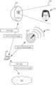
- FIG. 1illustrates an example of multi-sensor motion detection.
- camera 105includes field of vision 110 in which movement can be detected and if detected, video data can be generated to produce a video to play back what occurred within field of vision 110 .
- camera 105can include an IR sensor to determine motion and a CMOS image sensor that can be turned on to record video if the IR sensor detects motion within field of vision 110 .
- video 125(e.g., video data including image frames depicting the movement of intruder 115 within field of vision 110 ) can be generated by camera 105 using the image sensor and then provided to base station 130 .
- providing video 125 to base station 130can also be an indication that motion was detected.
- Radar sensor 140can be a supplemental sensor for detecting motion within field of vision 110 or in the general vicinity of field of vision 110 (e.g., more area than what is covered by field of vision 110 ) that can serve as a type of second opinion regarding whether the movement of the object within field of vision 110 is relevant or important for the user, or even if it is real.
- radar sensor 140can generate electromagnetic waves 160 that can be reflected off objects within field of vision 110 , including intruder 115 . By analyzing these reflections, radar sensor 140 can determine that motion is occurring within field of vision 110 . As a result, radar sensor 140 can provide information such as motion detected 135 to base station 130 to indicate that motion was detected via radar.
- both camera 105 and radar sensor 140can determine whether motion is occurring within field of vision 110 within the same or similar time. As a result, when intruder 115 crosses into field of vision 110 , both camera 105 and radar sensor 140 can alert base station of this detected movement.
- radar sensor 140can be integrated within base station 130 , radar sensor 140 may be a stand-alone device, radar sensor 140 can be integrated within camera 105 , or all of camera 105 , base station 130 , and radar sensor 140 can be integrated into a single device.
- Radar sensor 140can determine speed, distance from radar sensor 140 , direction (e.g., approaching or retreating from radar sensor 140 ), or other characteristics of the position, location, or movement of objects.
- Radar sensor 140can be a wide band radar, ultra-wideband (UWB) radar, continuous wave frequency modulation (CWFM) radar, or other type of radar.
- UWBultra-wideband
- CWFMcontinuous wave frequency modulation
- Base station 130can be communicatively coupled with camera 105 and radar sensor 140 via physical wiring or wireless technologies such as IEEE 802.11, Bluetooth, etc. Base station 130 can also be communicatively coupled with cloud server 155 , for example, via an Internet connection. Base station 130 can provide notifications of detected movement within field of vision 110 (e.g., the sidewalk leading up to a home's front door) to cloud server 155 , for example, via motion notification 150 . Upon receiving motion notification 150 , cloud server 155 can generate a message delivered to the user's (e.g., homeowner) smartphone providing an indication that motion was detected in the area where the user set up camera 105 (e.g., within field of vision 110 ). This can allow the user to be informed of a possible security situation at home.
- the user'se.g., homeowner
- Base station 130can also upload, or provide, video 125 to cloud server 155 .
- video 125can be the result of image sensor of camera 105 being used to record the activity occurring within field of vision 110 when the IR sensor of camera 105 was used to determine that motion has been detected.
- Video 125can be stored by cloud server 155 and provided to the user to view, for example, via a smartphone, web browser on a computer, etc. so that the nature of the detected motion can be determined. For example, in FIG. 1 , intruder 115 moving within field of vision 110 can be viewed by the user.
- IR sensormight have triggered the IR sensor to provide a false positive.
- Other examples of scenarios in which the IR sensor might produce a false positiveinclude temperature fluctuations, for example, by sunlight being incident upon the IR sensor.
- radar sensor 140can detect motion within field of vision 110 , but the IR sensor of camera 105 might not detect motion and, therefore, video might not be recorded using the image sensor of camera 105 .
- radar sensor 140(or another type supplemental sensor) detects motion, then this can be prioritized by base station 130 and used by base station 130 to provide data to camera 105 to begin recording.
- video 125can be generated and provided to cloud server 155 .
- FIG. 1uses radar sensor 140 , other types of sensors can be used.
- motioncan be detected using a wireless mesh network implementing an IEEE 802.11 compliant wireless network.
- FIG. 2illustrates an example of a block diagram for multi-sensor motion detecting using a radar sensor.
- motioncan be determined to be occurring within an area using an IR sensor ( 205 ).
- camera 105can include an IR sensor to detect motion occurring within field of vision 110 (e.g., the area that the IR sensor is pointing towards). The detection of the motion can be based on the IR sensor generating a voltage in response to heat detected in its field of vision. If the source of the heat moves, this results in a change in that voltage. Accordingly, this change in voltage can be used to determine that the IR sensor has detected motion.
- the IR sensorcan be a passive infrared (PIR) sensor.
- PIRpassive infrared
- This detection of motioncan be a first indication of motion within field of vision 110 .
- this first indicationcan be a false positive or be the result of motion that is of relatively no interest to a user and, therefore, should not be used to determine that motion has occurred.
- the detection of motioncan then be used to cause camera 105 to generate a video using an image sensor to visually depict that motion.
- Data regarding the motion and/or the videocan then be provided to and received by base station 130 ( 207 ).
- Motioncan also be determined to be occurring within an area using a radar sensor ( 210 ). This can be a second indication of motion of the same object as a double-checking or verification of the motion determined by the IR sensor of camera 105 .
- radar sensor 140can generate electromagnetic waves 160 and determine reflections of those waves off objects within field of vision 110 and determine whether there is movement upon an analysis of those reflections. Data regarding the motion can then be provided to and received by base station 130 as a determination of motion.
- the base stationcan then determine that both the IR sensor and the radar senor determined that motion occurred in the same or generally same area ( 213 ). This can be an indication that the motion of the object is not a false positive and that it is likely to be of interest for a user to be alerted regarding the presence of the object within field of view 110 .
- a notification indicating that motion was detected and/or a video of portraying the area when the motion was detectedcan then be provided to a cloud server ( 215 ) such that a user can be informed of the motion.
- video 125 and/or motion notification 150can be provided to cloud server 155 by base station 130 if both camera 105 and radar sensor 140 provide motion detected 120 and motion detected 130 , respectively, or if camera 130 provides a video.
- video 125can be generated by the image sensor of camera 105 and then provided to base station 130 .
- radar sensor 140also indicates that motion has occurred within field of vision 110
- video 125can then be uploaded to cloud server 155 . If radar sensor 140 did not indicate that motion occurred within field of vision 110 , then base station 130 might discard the video (e.g., not upload it to cloud server 155 ).
- base station 130might locally store video 125 for later viewing by the user rather than uploading to cloud server 155 if radar sensor 140 does not indicate that motion is detected.
- base station 130might provide video 125 to cloud server 155 along with information indicating that radar sensor 140 did not detect motion (i.e., that only the IR sensor of camera 105 detected motion within field of vision 110 ).
- Cloud server 155might then store video 125 , but not provide an alert to the user as this can be a false positive.
- Video 125can then be analyzed by cloud server 155 to determine why it was a false positive.
- video 125 that is related to a false positivecan be stored for later viewing by the user. For example, this can represent a video of less important or relevance to the user and, therefore, a notification might not be provided but the video still available for the user in case the user would like to view the video later.
- supplemental sensorsother than radar 140 in FIG. 1 can be used to provide a second opinion or determination regarding the presence of motion within field of view 110 .
- characteristics of a wireless network within the property in which camera 105 and base station 130 are withincan be used to determine that motion has occurred.
- Bluetoothe.g., implementing a personal area network (PAN)
- wifie.g., IEEE 802.11 implementing a wireless local area network (WLAN)
- WLANwireless local area network
- radio frequency (RF) characteristics of the wireless networkcan be used to determine that motion has occurred.
- the channel state information (CSI) in wireless communicationsprovides channel properties of a wireless communications link, for example, between base station 130 and a wireless access point (AP).
- CSIcan be provided by each packet as it is transmitted to or from base station 130 and an AP.
- the CSIcan include a significant amount of information that can be analyzed by a variety of methodologies to determine that motion is occurring within the physical space that the wireless network is implemented within. For example, changes or deviations in the expected amplitude or phase of the signals as indicated in the CSI can be used to determine that motion has occurred. Thus, characteristics or changes in those characteristics of the CSI can be used to determine that motion has occurred.
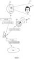
- FIG. 3illustrates an example of a block diagram for multi-sensor motion detecting using wireless data.
- motioncan be determined to have occurred in an area using an IR sensor ( 305 ).
- Motioncan also be determined using wireless data ( 310 ).
- base station 130can be using the same wireless network as one being provided by one or more access points.
- Base station 130can receive CSI data from these other access points and based on the CSI data, base station 130 can determine that motion has occurred in the area.
- a notification indicating that motion was detected and/or video depicting the motioncan then be provided to a cloud server ( 315 ). This can occur if base station 130 determines that motion was detected by the IR sensor of camera 105 and the CSI data.
- FIG. 4illustrates an example of adjusting motion detection thresholds.
- cloud server 405can include logic to determine whether any data or information used by camera 105 or radar sensor 140 used to detect motion should be adjusted. For example, if radar sensor 140 does not detect motion in an area that the IR sensor of camera 105 detected motion, then this discrepancy between the determinations of radar sensor 104 and camera 105 can be provided to cloud server 155 . In some implementations, video 125 can also be provided.
- Cloud server 155can then provide feedback 405 (e.g., based on the discrepancy, an analysis of video 125 , etc.) to base station 130 which can in turn provide motion threshold adjustment 415 to camera 105 .
- Motion threshold adjustment 415can include information regarding changes that camera 105 should implement such that the sensitivity of its motion detection is changed. This can include changing the characteristics of the motion that are used to determine whether motion is occurring within field of vision 110 . For example, if the IR sensor previously detected motion in a scenario that ended up being a false positive, then the motion determination sensitivity of camera 105 can be changed such that when the same scenario occurs, it does not indicate that meaningful motion occurred (i.e., no motion of interest to the homeowner occurred). This would result in the camera not determining that motion occurred within field of vision 110 even though before the adjustments were applied, the same type of motion would have triggered a determination that motion occurred.
- thiscan include changing the distance from the IR sensor in which motion can be determined.
- Motion threshold adjustment 415can be processed by camera 105 such that movement closer to the IR sensor would result in a motion determination while movement farther away would not result in a motion determination.
- the speed of motioncan be adjusted such that objects would need to move faster or slower for motion to qualify as detectable motion to result in recording video or providing a notification to the user regarding the motion.
- the expected trajectory of the objects within field of vision 110can be changed to change when camera 105 determines that motion has occurred. Thus, only some types of motion might be determined to be important or relevant to the user if the types of motion meets these motion thresholds.
- Base station 130can also provide motion threshold adjustment 410 to radar sensor 140 such that the motion thresholds for radar sensor 140 can also be changed in a similar manner.
- FIG. 5illustrates an example of a block diagram for adjusting motion detection thresholds.
- motioncan be determined to have occurred using an IR sensor ( 505 ).
- IR sensor505
- motion within field of view 110 of camera 105 in FIG. 5might occur and that motion might have characteristics resulting in a determination that motion of interest to a user is occurring within field of vision 110 . This can result in base station 130 being alerted to this motion.
- a supplemental sensorFor example, radar sensor 140 in FIG. 4 might not detect motion within field of view 110 . This information regarding the lack of motion can be provided to base station 130 and base station 130 can then determine that motion was determined using camera 105 but not radar sensor 140 . This can be indicative of a false positive of motion detection related to camera 105 .
- Base station 130can then determine how to adjust motion determination thresholds of the IR sensor to reduce false positives ( 515 ). For example, in FIG. 4 , base station 130 can provide information to cloud server 155 regarding the false positive as well as the motion thresholds used by camera 105 and/or radar sensor 140 when the characteristics of motion within field of view 110 is analyzed and determined to be motion of important or relevance to the user, as previously discussed. Any generated video data can also be provided. Cloud server 155 can analyze the received information and determine how to adjust the motion determination thresholds of the IR sensor to reduce these false positives. In another implementation, base station 130 can determine how to adjust the motion determination thresholds of the IR sensor without contacting cloud server 155 .
- base station 130can provide motion threshold adjustment 415 to camera 105 to update its motion thresholds such that different characteristics of motion would result in different determinations regarding movement occurring within field of vision 110 in the future. For example, camera 105 might be adjusted such that fewer determinations of motion can be determined.
- Camera 105 in FIG. 1can include radar sensor 140 integrated within it. Integrating radar sensor 140 into camera 105 can result in the same power supply (e.g., battery) used to power both the IR sensor of camera 105 and radar sensor 140 . However, use of radar sensor 140 might cause the battery of camera 105 to discharge quickly due to the higher power requirements to operate radar sensor 140 .
- the IR sensorcan have lower power requirements than radar sensor 140 .
- radar sensor 140can be initially turned off. When the IR sensor is triggered upon motion, this can also cause radar sensor 140 to be turned on to determine whether the motion can be verified using radar. After the determination of whether there is motion or after the operation of radar sensor 140 to allow for the determination is complete, radar sensor 140 can then be turned off. Thus, radar sensor 140 can be used only at times when it is to provide a supplemental determination of an object moving.
- radar sensor 140 of camera 105can be periodically turned on. For example, radar sensor 140 can be turned on for five minutes, then turned off for ten minutes, and then turned on again for five minutes, and so forth.
- camera 105can be optionally hard wired into a home's electrical system. Thus, camera 105 in this situation would not need to use a battery to operate radar sensor 140 .
- Camera 105can detect whether the power supply is a battery or the electrical system (e.g., connected with the electrical grid of an interconnected network for delivering electricity). If camera 105 is using a battery, then radar sensor 140 can be turned on and off as described above (i.e., when the IR sensor is triggered). If camera 105 is determined to be on the electrical system (i.e., not dependent on the battery), then radar sensor 140 can be turned on without the need to turn it off periodically.
- the operational parameters of radar sensor 140can also be adjusted to reduce power consumption and extend the battery life of radar sensor 140 and, therefore, extend how long radar sensor 140 can operate before needing to change or recharge the battery.
- transmission parameters related to how electromagnetic waves 160 are generated by radar sensor 140 and propagatedcan be adjusted.
- the amount of motion detected using the IR sensoris small (e.g., a small change in voltage produced by the IR sensor)
- this small amount of motionmight have a higher change of being a false positive.
- radar sensor 140can then be turned on to verify the results of the IR sensor.
- the amount of motionis large, then radar sensor 140 can remain off because a large amount of motion might have a lower change of being a false positive.
- the amount of motioncan be how fast the movement is, how large the object that is moving is, direction, acceleration, or other characteristics of motion as described herein.
- the transmission parameters related to how electromagnetic waves 160 are generatedcan be adjusted to be different than if the amount of motion is large. For example, the frequency or frequencies used (of electromagnetic waves 160 ), pulse width, amplitude, pulse repetition frequency (e.g., how often or how many pulses of electromagnetic waves 160 are emitted), or other characteristics can be changed to extend battery life in certain identified situations such as the amount of motion or movement.
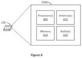
- FIG. 6illustrates an example of a simplified block diagram of an electronic device which may be used with particular implementations.
- the electronic device of FIG. 6can implement any of the functionalities and features discussed above, including base station 130 .
- the componentscan also be used to implement camera 105 and radar sensor 140 .
- FIG. 6portrays a high-level block diagram illustrating a processing device 2500 implementing base station 130 in which at least some operations described herein can be implemented.
- the block diagramcan also implement the other devices described herein, such as camera 105 and radar sensor 140 .
- the processing systemcan be a system that can run any of the methods/algorithms/techniques described above.
- the processing device 2500includes one or more processors 605 , memory 610 , antenna 615 , and one or more radios 620 .
- Processors 605may be or include, for example, one or more general-purpose programmable microprocessors or microprocessor cores, microcontrollers, application specific integrated circuits (ASICs), programmable gate arrays, or the like, or a combination of such devices.
- the processor(s) 605control the overall operation of the processing device 2500 .
- Memory 610may be or include one or more physical storage devices, which may be in the form of random access memory (RAM), read-only memory (ROM) (which may be erasable and programmable), flash memory, miniature hard disk drive, or other suitable type of storage device, or a combination of such devices.
- Memory 610may store data and instructions that configure the processor(s) 605 to execute operations in accordance with the techniques described above.
- Processing device 2500can also include communication devices that may be or include, for example, an Ethernet adapter, cable modem, Wi-Fi adapter, cellular transceiver, Bluetooth transceiver, or the like, or a combination thereof.
- processing device 2500can also include I/O devices that can include devices such as a display (which may be a touch screen display), audio speaker, keyboard, mouse or other pointing device, microphone, camera, etc.
- processing device 2500can also include radios 620 , for example, a different radio for each band that communication links can be established within.
- processing device 2500can also include one or more antennas 615 for aiding the establishing of the communication links.
- radio 620can generate a signal that is transmitted via antenna 615 .
- processes or blocksare presented in a given order, alternative embodiments may perform routines having steps, or employ systems having blocks, in a different order, and some processes or blocks may be deleted, moved, added, subdivided, combined, and/or modified to provide alternative or sub-combinations, or may be replicated (e.g., performed multiple times). Each of these processes or blocks may be implemented in a variety of different ways. In addition, while processes or blocks are at times shown as being performed in series, these processes or blocks may instead be performed in parallel, or may be performed at different times. When a process or step is “based on” a value or a computation, the process or step should be interpreted as based at least on that value or that computation.
- Machine-readable mediumincludes any mechanism that can store information in a form accessible by a machine (a machine may be, for example, a computer, network device, cellular phone, personal digital assistant (PDA), manufacturing tool, any device with one or more processors, etc.).
- a machine-accessible mediumincludes recordable/non-recordable media (e.g., read-only memory (ROM); random access memory (RAM); magnetic disk storage media; optical storage media; flash memory devices; etc.), etc.
- Physical and functional componentsassociated with processing device 2500 can be implemented as circuitry, firmware, software, other executable instructions, or any combination thereof.
- the functional componentscan be implemented in the form of special-purpose circuitry, in the form of one or more appropriately programmed processors, a single board chip, a field programmable gate array, a general-purpose computing device configured by executable instructions, a virtual machine configured by executable instructions, a cloud computing environment configured by executable instructions, or any combination thereof.
- the functional components describedcan be implemented as instructions on a tangible storage memory capable of being executed by a processor or other integrated circuit chip.
- the tangible storage memorycan be computer readable data storage.
- the tangible storage memorymay be volatile or non-volatile memory.
- the volatile memorymay be considered “non-transitory” in the sense that it is not a transitory signal.
- Memory space and storages described in the figurescan be implemented with the tangible storage memory as well, including volatile or non-volatile memory.
- Each of the functional componentsmay operate individually and independently of other functional components. Some or all of the functional components may be executed on the same host device or on separate devices. The separate devices can be coupled through one or more communication channels (e.g., wireless or wired channel) to coordinate their operations. Some or all of the functional components may be combined as one component. A single functional component may be divided into sub-components, each sub-component performing separate method step or method steps of the single component.
- At least some of the functional componentsshare access to a memory space.
- one functional componentmay access data accessed by or transformed by another functional component.
- the functional componentsmay be considered “coupled” to one another if they share a physical connection or a virtual connection, directly or indirectly, allowing data accessed or modified by one functional component to be accessed in another functional component.
- at least some of the functional componentscan be upgraded or modified remotely (e.g., by reconfiguring executable instructions that implements a portion of the functional components).
- Other arrays, systems and devices described abovemay include additional, fewer, or different functional components for various applications.
Landscapes
- Engineering & Computer Science (AREA)
- Signal Processing (AREA)
- Computer Networks & Wireless Communication (AREA)
- Multimedia (AREA)
- Physics & Mathematics (AREA)
- General Physics & Mathematics (AREA)
- Quality & Reliability (AREA)
- Electromagnetism (AREA)
- Theoretical Computer Science (AREA)
- Radar, Positioning & Navigation (AREA)
- Remote Sensing (AREA)
- Computer Security & Cryptography (AREA)
- Business, Economics & Management (AREA)
- Emergency Management (AREA)
- Software Systems (AREA)
- Computing Systems (AREA)
- Health & Medical Sciences (AREA)
- General Health & Medical Sciences (AREA)
- Human Computer Interaction (AREA)
- Computer Vision & Pattern Recognition (AREA)
- Environmental & Geological Engineering (AREA)
- Biomedical Technology (AREA)
- General Engineering & Computer Science (AREA)
- General Business, Economics & Management (AREA)
- Psychiatry (AREA)
- Social Psychology (AREA)
- Radar Systems Or Details Thereof (AREA)
Abstract
Description
Claims (18)
Priority Applications (3)
| Application Number | Priority Date | Filing Date | Title |
|---|---|---|---|
| US17/379,513US11575912B2 (en) | 2018-02-20 | 2021-07-19 | Multi-sensor motion detection |
| US18/149,446US12088826B2 (en) | 2018-02-20 | 2023-01-03 | Multi-sensor motion detection |
| US18/806,518US20240406415A1 (en) | 2018-02-20 | 2024-08-15 | Multi-sensor motion detection |
Applications Claiming Priority (3)
| Application Number | Priority Date | Filing Date | Title |
|---|---|---|---|
| US201862633017P | 2018-02-20 | 2018-02-20 | |
| US16/000,743US11102492B2 (en) | 2018-02-20 | 2018-06-05 | Multi-sensor motion detection |
| US17/379,513US11575912B2 (en) | 2018-02-20 | 2021-07-19 | Multi-sensor motion detection |
Related Parent Applications (1)
| Application Number | Title | Priority Date | Filing Date |
|---|---|---|---|
| US16/000,743ContinuationUS11102492B2 (en) | 2018-02-20 | 2018-06-05 | Multi-sensor motion detection |
Related Child Applications (1)
| Application Number | Title | Priority Date | Filing Date |
|---|---|---|---|
| US18/149,446ContinuationUS12088826B2 (en) | 2018-02-20 | 2023-01-03 | Multi-sensor motion detection |
Publications (2)
| Publication Number | Publication Date |
|---|---|
| US20210352300A1 US20210352300A1 (en) | 2021-11-11 |
| US11575912B2true US11575912B2 (en) | 2023-02-07 |
Family
ID=70612580
Family Applications (3)
| Application Number | Title | Priority Date | Filing Date |
|---|---|---|---|
| US16/000,743ActiveUS11102492B2 (en) | 2018-02-20 | 2018-06-05 | Multi-sensor motion detection |
| US17/379,513ActiveUS11575912B2 (en) | 2018-02-20 | 2021-07-19 | Multi-sensor motion detection |
| US18/149,446ActiveUS12088826B2 (en) | 2018-02-20 | 2023-01-03 | Multi-sensor motion detection |
Family Applications Before (1)
| Application Number | Title | Priority Date | Filing Date |
|---|---|---|---|
| US16/000,743ActiveUS11102492B2 (en) | 2018-02-20 | 2018-06-05 | Multi-sensor motion detection |
Family Applications After (1)
| Application Number | Title | Priority Date | Filing Date |
|---|---|---|---|
| US18/149,446ActiveUS12088826B2 (en) | 2018-02-20 | 2023-01-03 | Multi-sensor motion detection |
Country Status (2)
| Country | Link |
|---|---|
| US (3) | US11102492B2 (en) |
| CN (1) | CN110177247A (en) |
Families Citing this family (16)
| Publication number | Priority date | Publication date | Assignee | Title |
|---|---|---|---|---|
| EP3921668A2 (en) | 2019-02-06 | 2021-12-15 | Essence Security International (E.S.I.) Ltd. | Radar location system and method |
| US11585913B2 (en)* | 2019-03-07 | 2023-02-21 | Logistics And Supply Chain Multi Tech R&D Centre Limited | Ultra-wideband-based system and method for detecting properties associated with a movable object in an environment |
| US11243117B2 (en) | 2019-09-11 | 2022-02-08 | Jdrf Electromag Engineering Inc. | NIR motion detection system and method |
| CN110708835A (en)* | 2019-10-30 | 2020-01-17 | 江苏第二师范学院(江苏省教育科学研究院) | Intelligent lighting cloud monitoring system |
| DE102019135851A1 (en)* | 2019-12-30 | 2021-07-01 | Daimler Ag | Method for suppressing ambiguous measurement data from environmental sensors |
| IL276001A (en)* | 2020-07-12 | 2022-02-01 | Essence Security International Esi Ltd | Detecting an object in an environment |
| IL276002A (en) | 2020-07-12 | 2022-02-01 | Essence Security International Esi Ltd | Detecting an object in an environment |
| CN112489390B (en)* | 2020-07-13 | 2022-05-10 | 北京宏远汇通网络科技有限公司 | Security node collaborative alarm method based on intelligent security |
| IL282448A (en)* | 2021-04-19 | 2022-11-01 | Essence Security International Esi Ltd | Detecting an object in an environment |
| US11952121B2 (en)* | 2021-06-17 | 2024-04-09 | B/E Aerospace, Inc. | Sensor systems and methods for an aircraft lavatory |
| US11758223B2 (en)* | 2021-12-23 | 2023-09-12 | The Nielsen Company (Us), Llc | Apparatus, systems, and methods for user presence detection for audience monitoring |
| EP4207120A1 (en)* | 2021-12-29 | 2023-07-05 | Verisure Sàrl | Security monitoring system |
| US20230410620A1 (en)* | 2022-06-15 | 2023-12-21 | Arlo Technologies, Inc. | Electronic Monitoring System with Intuitive Activity Zone Definition |
| CN115460746A (en)* | 2022-09-23 | 2022-12-09 | 深圳市欧瑞博科技股份有限公司 | Lamp effect control method and device, computer equipment and computer readable storage medium |
| US20240179600A1 (en)* | 2022-11-30 | 2024-05-30 | T-Mobile Usa, Inc. | Service-dynamic user equipment (ue) handover |
| TWI858709B (en)* | 2023-05-16 | 2024-10-11 | 大鵬科技股份有限公司 | Intruder detection system |
Citations (100)
| Publication number | Priority date | Publication date | Assignee | Title |
|---|---|---|---|---|
| US20020059627A1 (en) | 1996-11-27 | 2002-05-16 | Islam Farhad Fuad | Agent-enabled real-time quality of service system for audio-video media |
| US20020105921A1 (en) | 2001-02-02 | 2002-08-08 | Francois Sawyer | Radio network emulator for a packet core network |
| US20020181637A1 (en) | 2001-05-31 | 2002-12-05 | Sumie Nakabayashi | Radio communication method and apparatus capable of changing transmission rate at every other party |
| US20030055908A1 (en) | 2001-09-20 | 2003-03-20 | International Business Machines Corporation | Controlling throughput of message requests in a messaging system |
| US20030063277A1 (en) | 2001-09-28 | 2003-04-03 | Kennedy William P. | Method for the calibration and alignment of multiple multi-axis motion stages for optical alignment to a planar waveguide device and system |
| US20030193525A1 (en) | 2002-04-11 | 2003-10-16 | Nygaard Richard A. | Expedited selection of items from a list within a drop down menu of an eye diagram analyzer |
| US20050086569A1 (en) | 2003-09-25 | 2005-04-21 | Hiddink Gerrit W. | Method and apparatus for rate fallback in a wireless communication system |
| US20050169209A1 (en) | 2004-01-30 | 2005-08-04 | Allen Miu | Systems and methods for multi-access point transmission of data using a plurality of access points |
| WO2006075052A1 (en) | 2005-01-13 | 2006-07-20 | Elektrobit Production Solutions Oy. | Method for forming images, method for testing electronic devices; and test apparatus, test chamber and test system |
| US20060232673A1 (en)* | 2005-04-19 | 2006-10-19 | Objectvideo, Inc. | Video-based human verification system and method |
| WO2007047419A2 (en)* | 2005-10-14 | 2007-04-26 | Bae Systems Information And Electronic Systems Integration Inc. | Motion detection system using cw radar in combination with additional sensors |
| US20070153916A1 (en) | 2005-12-30 | 2007-07-05 | Sharp Laboratories Of America, Inc. | Wireless video transmission system |
| US20080020746A1 (en) | 2006-07-18 | 2008-01-24 | Thomas Alexandar | Method and apparatus for controllable simulation of mobility |
| US20080026748A1 (en) | 2006-07-31 | 2008-01-31 | Thomas Alexander | Method and apparatus for wireless mobility measurements |
| US20080025378A1 (en) | 1993-05-11 | 2008-01-31 | Mahany Ronald L | System and method for determining data rate |
| US20080112315A1 (en) | 2006-11-10 | 2008-05-15 | Microsoft Corporation | Peer-to-peer aided live video sharing system |
| US20090022222A1 (en) | 2006-03-29 | 2009-01-22 | Huawei Technologies Co., Ltd. | Method and device for multi-view encoding/decoding using disparity vector |
| WO2009048660A2 (en) | 2007-07-16 | 2009-04-16 | Raytheon Company | System and method of moving target based calibration of non-uniformity compensation for optical imagers |
| US7539489B1 (en) | 2003-04-04 | 2009-05-26 | Veriwave, Incorporated | Location-based testing for wireless data communication networks |
| US20090273679A1 (en) | 2008-05-01 | 2009-11-05 | Apple Inc. | Apparatus and method for calibrating image capture devices |
| US20090290019A1 (en) | 2008-02-25 | 2009-11-26 | Aai Corporation | System, method and computer program product for integration of sensor and weapon systems with a graphical user interface |
| US20100080205A1 (en) | 2007-04-18 | 2010-04-01 | Nxp B.V. | Rate recovery mechanisim, method and system for a wlan-bluetooth coexistance system |
| US20100097472A1 (en) | 2008-10-21 | 2010-04-22 | Honeywell International Inc. | Method of efficient camera control and hand over in surveillance management |
| US20100109934A1 (en) | 2008-09-30 | 2010-05-06 | Cooper Technologies Company | Doppler radar motion detector for an outdoor light fixture |
| JP2010232819A (en) | 2009-03-26 | 2010-10-14 | Nec Infrontia Corp | Retransmission control method and radio communication device |
| US20100285753A1 (en) | 2009-05-06 | 2010-11-11 | Michael Foegelle | Systems and methods for simulating a multipath radio frequency environment |
| US20120314875A1 (en) | 2011-06-09 | 2012-12-13 | Samsung Electronics Co., Ltd. | Method and apparatus for encoding and decoding 3-dimensional audio signal |
| US20130021912A1 (en) | 2011-07-22 | 2013-01-24 | Keir Finlow-Bates | System and method for testing wireless position locating |
| US20130053653A1 (en) | 2011-08-29 | 2013-02-28 | General Electric Company | Radar based systems and methods for monitoring a subject |
| US20130089039A1 (en) | 2011-10-07 | 2013-04-11 | Apple Inc. | Channel selection in a multiple carrier multiple radio access technology network |
| US20130128947A1 (en) | 2011-11-18 | 2013-05-23 | At&T Intellectual Property I, L.P. | System and method for automatically selecting encoding/decoding for streaming media |
| US20140036993A1 (en) | 2011-04-15 | 2014-02-06 | Sk Planet Co., Ltd. | Adaptive video transcoding method and system |
| US20140051379A1 (en) | 2012-08-14 | 2014-02-20 | Shriram Ganesh | Methods, systems and devices for prioritizing access to wireless networks |
| US20140064120A1 (en) | 2012-08-29 | 2014-03-06 | Samsung Electronics Co., Ltd. | Wireless communication system with rate selection mechanism and method of operation thereof |
| US20140092755A1 (en) | 2012-09-28 | 2014-04-03 | Adriaan van de Ven | Reducing wireless reconnection time of a computing device |
| US20140115114A1 (en) | 2012-10-22 | 2014-04-24 | Spotify AS | Systems and methods for pre-fetching media content |
| US20140169509A1 (en) | 2012-12-18 | 2014-06-19 | Panasonic Avionics Corporation | Antenna system calibration |
| US20140169195A1 (en) | 2012-12-14 | 2014-06-19 | Realtek Semiconductor Corporation | Wireless transmission rate adjustment method |
| US20140240491A1 (en) | 2013-02-28 | 2014-08-28 | iStoc Oy | Portable lateral test reader |
| US20140269655A1 (en) | 2013-03-14 | 2014-09-18 | Qualcomm Incorporated | Dynamic Rate Control In WiFi Systems |
| WO2014144628A2 (en)* | 2013-03-15 | 2014-09-18 | Master Lock Company | Cameras and networked security systems and methods |
| US8855035B2 (en) | 2009-11-24 | 2014-10-07 | Orange | Access control for a service subscription |
| US20140307707A1 (en) | 2013-04-13 | 2014-10-16 | Telefonaktiebolaget L M Ericsson (Publ) | Network-instructed handover from wlan to another radio access network |
| US20140358592A1 (en) | 2013-05-31 | 2014-12-04 | OneEvent Technologies, LLC | Sensors for usage-based property insurance |
| US20140368601A1 (en) | 2013-05-04 | 2014-12-18 | Christopher deCharms | Mobile security technology |
| US20150185857A1 (en) | 2012-06-08 | 2015-07-02 | Kmt Global Inc | User interface method and apparatus based on spatial location recognition |
| US20150229426A1 (en) | 2012-10-23 | 2015-08-13 | Huawei Technologies Co., Ltd. | Data signal coordinated transmitting and receiving methods and apparatus |
| US20150312572A1 (en) | 2014-03-13 | 2015-10-29 | Wowza Media Systems, LLC | Adjusting encoding parameters at a mobile device based on a change in available network bandwidth |
| US9179495B1 (en) | 2003-07-08 | 2015-11-03 | Hewlett-Packard Development Company, L.P. | Implementing “all wireless” network over WiFi equipment using “scheduled TDMA” |
| US20150319411A1 (en) | 2013-07-26 | 2015-11-05 | SkyBell Technologies, Inc. | Doorbell communication systems and methods |
| US20150349859A1 (en) | 2012-10-08 | 2015-12-03 | Netgear, Inc. | Near-Field MIMO Wireless Test Systems, Structures, and Processes |
| US20150381310A1 (en) | 2013-08-09 | 2015-12-31 | Telefonaktiebolaget L M Ericsson (Publ) | Method and Radio Node for Enabling Use of High Order Modulation in a Radio Communication with a User Equipment |
| US20160114887A1 (en) | 2002-10-01 | 2016-04-28 | Dylan T X Zhou | Amphibious vertical takeoff and landing unmanned system and flying car with multiple aerial and aquatic flight modes for capturing panoramic virtual reality views, interactive video and transportation with mobile and wearable application |
| US20160125714A1 (en)* | 2014-11-04 | 2016-05-05 | Canary Connect, Inc. | Video recording with security/safety monitoring device |
| US20160165620A1 (en) | 2013-07-29 | 2016-06-09 | Lenel Systems International, Inc. | Systems and methods for integrated security access control for video and audio streaming |
| US9451484B2 (en) | 2010-04-16 | 2016-09-20 | Spirent Communications, Inc. | WiFi positioning bench test method and instrument |
| US20160278104A1 (en) | 2015-03-17 | 2016-09-22 | Gainspan Corporation | Determining transmission rates when transmitting parallel data streams from a wireless station of a wireless network |
| US20160337243A1 (en) | 2015-05-17 | 2016-11-17 | At&T Intellectual Property I, L.P. | Optimized Routing in Connected Environments |
| US20160366702A1 (en) | 2014-02-14 | 2016-12-15 | Nec Communication Systems, Ltd | Wireless communication terminal |
| US20170055179A1 (en) | 2015-08-21 | 2017-02-23 | Microsoft Technology Licensing, Llc | Dynamic channel selection in a wireless communication network |
| US20170070732A1 (en) | 2015-09-09 | 2017-03-09 | 6115187 Canada, d/b/a ImmerVision, Inc. | Method for designing an optimization apparatus for a camera having a lens with non-uniform parameters to be imaged as a lens with uniform parameters |
| US20170078242A1 (en) | 2015-09-10 | 2017-03-16 | Media Global Links Co., Ltd. | Video signal transmission system |
| CN106534634A (en) | 2016-11-08 | 2017-03-22 | 天津华来科技有限公司 | Monitoring camera |
| US20170123058A1 (en)* | 2015-11-04 | 2017-05-04 | University Of Hawaii | Systems and methods for detection of occupancy using radio waves |
| US20170162225A1 (en)* | 2015-12-04 | 2017-06-08 | BOT Home Automation, Inc. | Motion detection for a/v recording and communication devices |
| US20170163944A1 (en)* | 2015-12-04 | 2017-06-08 | BOT Home Automation, Inc. | Motion detection for a/v recording and communication devices |
| US20170180442A1 (en) | 2015-12-21 | 2017-06-22 | Intel Corporation | Telemetry based feedback for improved media streaming |
| CN106954026A (en) | 2017-04-27 | 2017-07-14 | 盯盯拍(深圳)技术股份有限公司 | Shooting method and trigger monitoring device |
| US9712814B2 (en) | 2015-04-01 | 2017-07-18 | Fujifilm Corporation | Imaging device and imaging method |
| US20170237673A1 (en) | 2016-02-16 | 2017-08-17 | Belden, Inc. | Systems and methods for retransmission rate selection to support fast moving devices |
| US20170244712A1 (en) | 2016-02-22 | 2017-08-24 | At&T Intellectual Property I, L.P. | Dynamic passcodes in association with a wireless access point |
| US20170242129A1 (en) | 2016-02-18 | 2017-08-24 | Verkotan Oy | Testing method and arrangement for GPS positioning measurements |
| US20170301203A1 (en) | 2016-04-15 | 2017-10-19 | Vivint, Inc. | Reducing bandwidth via voice detection |
| US20170301201A1 (en)* | 2006-11-20 | 2017-10-19 | Axis Ab | Wireless network camera systems |
| US9906722B1 (en)* | 2016-04-07 | 2018-02-27 | Ambarella, Inc. | Power-saving battery-operated camera |
| US9996750B2 (en) | 2016-06-01 | 2018-06-12 | Gopro, Inc. | On-camera video capture, classification, and processing |
| US10033436B2 (en) | 2016-08-24 | 2018-07-24 | Cisco Technology, Inc. | Power over wireless energy recharge (POWER) |
| US10044104B1 (en) | 2017-07-14 | 2018-08-07 | Rohde & Schwarz Gmbh & Co. Kg | Test arrangement and test method |
| US20180306904A1 (en) | 2017-04-24 | 2018-10-25 | Honeywell International Inc. | System and method for testing integrated radar systems |
| US20180308328A1 (en)* | 2017-04-20 | 2018-10-25 | Ring Inc. | Automatic adjusting of day-night sensitivity for motion detection in audio/video recording and communication devices |
| US20180357870A1 (en)* | 2017-06-07 | 2018-12-13 | Amazon Technologies, Inc. | Behavior-aware security systems and associated methods |
| US20180375594A1 (en) | 2015-12-16 | 2018-12-27 | Ranlos Ab | Method and apparatus for testing wireless communication to vehicles |
| US10177965B1 (en) | 2016-11-10 | 2019-01-08 | Amazon Technologies, Inc. | Live media encoding failover system |
| US20190014388A1 (en) | 2017-07-07 | 2019-01-10 | Verizon Patent And Licensing Inc. | Resource based-video quality adjustment |
| US20190020827A1 (en)* | 2017-07-12 | 2019-01-17 | Amazon Technologies, Inc. | Pre-roll image capture implemented by a power-limited security device |
| US20190132371A1 (en) | 2017-11-02 | 2019-05-02 | Arris Enterprises Llc | Approach to live multi-camera streaming of events with hand-held cameras |
| US20190162769A1 (en) | 2017-11-27 | 2019-05-30 | Omnivision Technologies, Inc. | Electromagnetic interference (emi) evaluation system for image sensors |
| US20190174330A1 (en)* | 2017-12-06 | 2019-06-06 | Beijing University Of Posts & Telecommunications | Sensing recognition method and device based on wireless communication signals |
| US20190200013A1 (en) | 2017-12-27 | 2019-06-27 | Omnivision Technologies, Inc. | Embedded multimedia systems with adaptive rate control for power efficient video streaming |
| US20190202657A1 (en) | 2017-12-28 | 2019-07-04 | Otis Elevator Company | Testing for wireless beacons of elevator system and field installation of the elevator system |
| US20190222897A1 (en) | 2013-07-11 | 2019-07-18 | Dejero Labs Inc. | Systems and methods for transmission of data streams |
| US20190261370A1 (en) | 2018-02-20 | 2019-08-22 | Netgear, Inc. | Band steering for a low power device |
| CN110177393A (en) | 2018-02-20 | 2019-08-27 | 网件公司 | The wireless network connection and registration of power saving for low power consuming devices |
| CN110177835A (en) | 2016-11-30 | 2019-08-27 | 米其林集团总公司 | Shear band with super LHR low hysteresis rubber |
| US20190282897A1 (en) | 2016-06-13 | 2019-09-19 | Sony Interactive Entertainment America Llc | Browser-based cloud gaming |
| US10425638B2 (en) | 2017-01-23 | 2019-09-24 | Multimedia Image Solution Limited | Equipment and method for promptly performing calibration and verification of intrinsic and extrinsic parameters of a plurality of image capturing elements installed on electronic device |
| US20190364505A1 (en) | 2016-11-03 | 2019-11-28 | Interdigital Patent Holdings, Inc. | Methods for efficient power saving for wake up radios |
| US10643412B1 (en)* | 2019-07-09 | 2020-05-05 | Frank Yang | Smart lock device and method |
| US10986717B1 (en)* | 2012-08-17 | 2021-04-20 | Kuna Systems Corporation | Reduced false alarms for outdoor IP security cameras |
| US11232688B1 (en)* | 2017-11-29 | 2022-01-25 | Amazon Technologies, Inc. | Auto-configuration for a motion detector of a security device |
- 2018
- 2018-06-05USUS16/000,743patent/US11102492B2/enactiveActive
- 2019
- 2019-02-20CNCN201910135330.4Apatent/CN110177247A/enactivePending
- 2021
- 2021-07-19USUS17/379,513patent/US11575912B2/enactiveActive
- 2023
- 2023-01-03USUS18/149,446patent/US12088826B2/enactiveActive
Patent Citations (101)
| Publication number | Priority date | Publication date | Assignee | Title |
|---|---|---|---|---|
| US20080025378A1 (en) | 1993-05-11 | 2008-01-31 | Mahany Ronald L | System and method for determining data rate |
| US20020059627A1 (en) | 1996-11-27 | 2002-05-16 | Islam Farhad Fuad | Agent-enabled real-time quality of service system for audio-video media |
| US20020105921A1 (en) | 2001-02-02 | 2002-08-08 | Francois Sawyer | Radio network emulator for a packet core network |
| US20020181637A1 (en) | 2001-05-31 | 2002-12-05 | Sumie Nakabayashi | Radio communication method and apparatus capable of changing transmission rate at every other party |
| US20030055908A1 (en) | 2001-09-20 | 2003-03-20 | International Business Machines Corporation | Controlling throughput of message requests in a messaging system |
| US20030063277A1 (en) | 2001-09-28 | 2003-04-03 | Kennedy William P. | Method for the calibration and alignment of multiple multi-axis motion stages for optical alignment to a planar waveguide device and system |
| US20030193525A1 (en) | 2002-04-11 | 2003-10-16 | Nygaard Richard A. | Expedited selection of items from a list within a drop down menu of an eye diagram analyzer |
| US20160114887A1 (en) | 2002-10-01 | 2016-04-28 | Dylan T X Zhou | Amphibious vertical takeoff and landing unmanned system and flying car with multiple aerial and aquatic flight modes for capturing panoramic virtual reality views, interactive video and transportation with mobile and wearable application |
| US7539489B1 (en) | 2003-04-04 | 2009-05-26 | Veriwave, Incorporated | Location-based testing for wireless data communication networks |
| US9179495B1 (en) | 2003-07-08 | 2015-11-03 | Hewlett-Packard Development Company, L.P. | Implementing “all wireless” network over WiFi equipment using “scheduled TDMA” |
| US20050086569A1 (en) | 2003-09-25 | 2005-04-21 | Hiddink Gerrit W. | Method and apparatus for rate fallback in a wireless communication system |
| US20050169209A1 (en) | 2004-01-30 | 2005-08-04 | Allen Miu | Systems and methods for multi-access point transmission of data using a plurality of access points |
| WO2006075052A1 (en) | 2005-01-13 | 2006-07-20 | Elektrobit Production Solutions Oy. | Method for forming images, method for testing electronic devices; and test apparatus, test chamber and test system |
| US20060232673A1 (en)* | 2005-04-19 | 2006-10-19 | Objectvideo, Inc. | Video-based human verification system and method |
| WO2007047419A2 (en)* | 2005-10-14 | 2007-04-26 | Bae Systems Information And Electronic Systems Integration Inc. | Motion detection system using cw radar in combination with additional sensors |
| US20070153916A1 (en) | 2005-12-30 | 2007-07-05 | Sharp Laboratories Of America, Inc. | Wireless video transmission system |
| US20090022222A1 (en) | 2006-03-29 | 2009-01-22 | Huawei Technologies Co., Ltd. | Method and device for multi-view encoding/decoding using disparity vector |
| US20080020746A1 (en) | 2006-07-18 | 2008-01-24 | Thomas Alexandar | Method and apparatus for controllable simulation of mobility |
| US20080026748A1 (en) | 2006-07-31 | 2008-01-31 | Thomas Alexander | Method and apparatus for wireless mobility measurements |
| US20080112315A1 (en) | 2006-11-10 | 2008-05-15 | Microsoft Corporation | Peer-to-peer aided live video sharing system |
| US20170301201A1 (en)* | 2006-11-20 | 2017-10-19 | Axis Ab | Wireless network camera systems |
| US20100080205A1 (en) | 2007-04-18 | 2010-04-01 | Nxp B.V. | Rate recovery mechanisim, method and system for a wlan-bluetooth coexistance system |
| WO2009048660A2 (en) | 2007-07-16 | 2009-04-16 | Raytheon Company | System and method of moving target based calibration of non-uniformity compensation for optical imagers |
| US20090290019A1 (en) | 2008-02-25 | 2009-11-26 | Aai Corporation | System, method and computer program product for integration of sensor and weapon systems with a graphical user interface |
| US20090273679A1 (en) | 2008-05-01 | 2009-11-05 | Apple Inc. | Apparatus and method for calibrating image capture devices |
| US20100109934A1 (en) | 2008-09-30 | 2010-05-06 | Cooper Technologies Company | Doppler radar motion detector for an outdoor light fixture |
| US20100097472A1 (en) | 2008-10-21 | 2010-04-22 | Honeywell International Inc. | Method of efficient camera control and hand over in surveillance management |
| JP2010232819A (en) | 2009-03-26 | 2010-10-14 | Nec Infrontia Corp | Retransmission control method and radio communication device |
| US20100285753A1 (en) | 2009-05-06 | 2010-11-11 | Michael Foegelle | Systems and methods for simulating a multipath radio frequency environment |
| US8855035B2 (en) | 2009-11-24 | 2014-10-07 | Orange | Access control for a service subscription |
| US9451484B2 (en) | 2010-04-16 | 2016-09-20 | Spirent Communications, Inc. | WiFi positioning bench test method and instrument |
| US20140036993A1 (en) | 2011-04-15 | 2014-02-06 | Sk Planet Co., Ltd. | Adaptive video transcoding method and system |
| US20120314875A1 (en) | 2011-06-09 | 2012-12-13 | Samsung Electronics Co., Ltd. | Method and apparatus for encoding and decoding 3-dimensional audio signal |
| US20130021912A1 (en) | 2011-07-22 | 2013-01-24 | Keir Finlow-Bates | System and method for testing wireless position locating |
| US20130053653A1 (en) | 2011-08-29 | 2013-02-28 | General Electric Company | Radar based systems and methods for monitoring a subject |
| US20130089039A1 (en) | 2011-10-07 | 2013-04-11 | Apple Inc. | Channel selection in a multiple carrier multiple radio access technology network |
| US20130128947A1 (en) | 2011-11-18 | 2013-05-23 | At&T Intellectual Property I, L.P. | System and method for automatically selecting encoding/decoding for streaming media |
| US20150185857A1 (en) | 2012-06-08 | 2015-07-02 | Kmt Global Inc | User interface method and apparatus based on spatial location recognition |
| US20140051379A1 (en) | 2012-08-14 | 2014-02-20 | Shriram Ganesh | Methods, systems and devices for prioritizing access to wireless networks |
| US10986717B1 (en)* | 2012-08-17 | 2021-04-20 | Kuna Systems Corporation | Reduced false alarms for outdoor IP security cameras |
| US20140064120A1 (en) | 2012-08-29 | 2014-03-06 | Samsung Electronics Co., Ltd. | Wireless communication system with rate selection mechanism and method of operation thereof |
| US20140092755A1 (en) | 2012-09-28 | 2014-04-03 | Adriaan van de Ven | Reducing wireless reconnection time of a computing device |
| US20150349859A1 (en) | 2012-10-08 | 2015-12-03 | Netgear, Inc. | Near-Field MIMO Wireless Test Systems, Structures, and Processes |
| US20140115114A1 (en) | 2012-10-22 | 2014-04-24 | Spotify AS | Systems and methods for pre-fetching media content |
| US20150229426A1 (en) | 2012-10-23 | 2015-08-13 | Huawei Technologies Co., Ltd. | Data signal coordinated transmitting and receiving methods and apparatus |
| US20140169195A1 (en) | 2012-12-14 | 2014-06-19 | Realtek Semiconductor Corporation | Wireless transmission rate adjustment method |
| US20140169509A1 (en) | 2012-12-18 | 2014-06-19 | Panasonic Avionics Corporation | Antenna system calibration |
| US20140240491A1 (en) | 2013-02-28 | 2014-08-28 | iStoc Oy | Portable lateral test reader |
| US20140269655A1 (en) | 2013-03-14 | 2014-09-18 | Qualcomm Incorporated | Dynamic Rate Control In WiFi Systems |
| US20160105644A1 (en)* | 2013-03-15 | 2016-04-14 | Vardr Pty. Ltd. | Cameras and networked security systems and methods |
| WO2014144628A2 (en)* | 2013-03-15 | 2014-09-18 | Master Lock Company | Cameras and networked security systems and methods |
| US20140307707A1 (en) | 2013-04-13 | 2014-10-16 | Telefonaktiebolaget L M Ericsson (Publ) | Network-instructed handover from wlan to another radio access network |
| US20140368601A1 (en) | 2013-05-04 | 2014-12-18 | Christopher deCharms | Mobile security technology |
| US20140358592A1 (en) | 2013-05-31 | 2014-12-04 | OneEvent Technologies, LLC | Sensors for usage-based property insurance |
| US20190222897A1 (en) | 2013-07-11 | 2019-07-18 | Dejero Labs Inc. | Systems and methods for transmission of data streams |
| US20150319411A1 (en) | 2013-07-26 | 2015-11-05 | SkyBell Technologies, Inc. | Doorbell communication systems and methods |
| US20160165620A1 (en) | 2013-07-29 | 2016-06-09 | Lenel Systems International, Inc. | Systems and methods for integrated security access control for video and audio streaming |
| US20150381310A1 (en) | 2013-08-09 | 2015-12-31 | Telefonaktiebolaget L M Ericsson (Publ) | Method and Radio Node for Enabling Use of High Order Modulation in a Radio Communication with a User Equipment |
| US20160366702A1 (en) | 2014-02-14 | 2016-12-15 | Nec Communication Systems, Ltd | Wireless communication terminal |
| US20150312572A1 (en) | 2014-03-13 | 2015-10-29 | Wowza Media Systems, LLC | Adjusting encoding parameters at a mobile device based on a change in available network bandwidth |
| US20160125714A1 (en)* | 2014-11-04 | 2016-05-05 | Canary Connect, Inc. | Video recording with security/safety monitoring device |
| US20160278104A1 (en) | 2015-03-17 | 2016-09-22 | Gainspan Corporation | Determining transmission rates when transmitting parallel data streams from a wireless station of a wireless network |
| US9712814B2 (en) | 2015-04-01 | 2017-07-18 | Fujifilm Corporation | Imaging device and imaging method |
| US20160337243A1 (en) | 2015-05-17 | 2016-11-17 | At&T Intellectual Property I, L.P. | Optimized Routing in Connected Environments |
| US20170055179A1 (en) | 2015-08-21 | 2017-02-23 | Microsoft Technology Licensing, Llc | Dynamic channel selection in a wireless communication network |
| US20170070732A1 (en) | 2015-09-09 | 2017-03-09 | 6115187 Canada, d/b/a ImmerVision, Inc. | Method for designing an optimization apparatus for a camera having a lens with non-uniform parameters to be imaged as a lens with uniform parameters |
| US20170078242A1 (en) | 2015-09-10 | 2017-03-16 | Media Global Links Co., Ltd. | Video signal transmission system |
| US20170123058A1 (en)* | 2015-11-04 | 2017-05-04 | University Of Hawaii | Systems and methods for detection of occupancy using radio waves |
| US20170163944A1 (en)* | 2015-12-04 | 2017-06-08 | BOT Home Automation, Inc. | Motion detection for a/v recording and communication devices |
| US20170162225A1 (en)* | 2015-12-04 | 2017-06-08 | BOT Home Automation, Inc. | Motion detection for a/v recording and communication devices |
| US20180375594A1 (en) | 2015-12-16 | 2018-12-27 | Ranlos Ab | Method and apparatus for testing wireless communication to vehicles |
| US20170180442A1 (en) | 2015-12-21 | 2017-06-22 | Intel Corporation | Telemetry based feedback for improved media streaming |
| US20170237673A1 (en) | 2016-02-16 | 2017-08-17 | Belden, Inc. | Systems and methods for retransmission rate selection to support fast moving devices |
| US20170242129A1 (en) | 2016-02-18 | 2017-08-24 | Verkotan Oy | Testing method and arrangement for GPS positioning measurements |
| US20170244712A1 (en) | 2016-02-22 | 2017-08-24 | At&T Intellectual Property I, L.P. | Dynamic passcodes in association with a wireless access point |
| US9906722B1 (en)* | 2016-04-07 | 2018-02-27 | Ambarella, Inc. | Power-saving battery-operated camera |
| US20170301203A1 (en) | 2016-04-15 | 2017-10-19 | Vivint, Inc. | Reducing bandwidth via voice detection |
| US9996750B2 (en) | 2016-06-01 | 2018-06-12 | Gopro, Inc. | On-camera video capture, classification, and processing |
| US20190282897A1 (en) | 2016-06-13 | 2019-09-19 | Sony Interactive Entertainment America Llc | Browser-based cloud gaming |
| US10033436B2 (en) | 2016-08-24 | 2018-07-24 | Cisco Technology, Inc. | Power over wireless energy recharge (POWER) |
| US20190364505A1 (en) | 2016-11-03 | 2019-11-28 | Interdigital Patent Holdings, Inc. | Methods for efficient power saving for wake up radios |
| CN106534634A (en) | 2016-11-08 | 2017-03-22 | 天津华来科技有限公司 | Monitoring camera |
| US10177965B1 (en) | 2016-11-10 | 2019-01-08 | Amazon Technologies, Inc. | Live media encoding failover system |
| CN110177835A (en) | 2016-11-30 | 2019-08-27 | 米其林集团总公司 | Shear band with super LHR low hysteresis rubber |
| US10425638B2 (en) | 2017-01-23 | 2019-09-24 | Multimedia Image Solution Limited | Equipment and method for promptly performing calibration and verification of intrinsic and extrinsic parameters of a plurality of image capturing elements installed on electronic device |
| US20180308328A1 (en)* | 2017-04-20 | 2018-10-25 | Ring Inc. | Automatic adjusting of day-night sensitivity for motion detection in audio/video recording and communication devices |
| US20180306904A1 (en) | 2017-04-24 | 2018-10-25 | Honeywell International Inc. | System and method for testing integrated radar systems |
| CN106954026A (en) | 2017-04-27 | 2017-07-14 | 盯盯拍(深圳)技术股份有限公司 | Shooting method and trigger monitoring device |
| US20180357870A1 (en)* | 2017-06-07 | 2018-12-13 | Amazon Technologies, Inc. | Behavior-aware security systems and associated methods |
| US20190014388A1 (en) | 2017-07-07 | 2019-01-10 | Verizon Patent And Licensing Inc. | Resource based-video quality adjustment |
| US20190020827A1 (en)* | 2017-07-12 | 2019-01-17 | Amazon Technologies, Inc. | Pre-roll image capture implemented by a power-limited security device |
| US10044104B1 (en) | 2017-07-14 | 2018-08-07 | Rohde & Schwarz Gmbh & Co. Kg | Test arrangement and test method |
| US20190132371A1 (en) | 2017-11-02 | 2019-05-02 | Arris Enterprises Llc | Approach to live multi-camera streaming of events with hand-held cameras |
| US20190162769A1 (en) | 2017-11-27 | 2019-05-30 | Omnivision Technologies, Inc. | Electromagnetic interference (emi) evaluation system for image sensors |
| US11232688B1 (en)* | 2017-11-29 | 2022-01-25 | Amazon Technologies, Inc. | Auto-configuration for a motion detector of a security device |
| US20190174330A1 (en)* | 2017-12-06 | 2019-06-06 | Beijing University Of Posts & Telecommunications | Sensing recognition method and device based on wireless communication signals |
| US20190200013A1 (en) | 2017-12-27 | 2019-06-27 | Omnivision Technologies, Inc. | Embedded multimedia systems with adaptive rate control for power efficient video streaming |
| US20190202657A1 (en) | 2017-12-28 | 2019-07-04 | Otis Elevator Company | Testing for wireless beacons of elevator system and field installation of the elevator system |
| US20190261370A1 (en) | 2018-02-20 | 2019-08-22 | Netgear, Inc. | Band steering for a low power device |
| CN110177393A (en) | 2018-02-20 | 2019-08-27 | 网件公司 | The wireless network connection and registration of power saving for low power consuming devices |
| US10643412B1 (en)* | 2019-07-09 | 2020-05-05 | Frank Yang | Smart lock device and method |
Non-Patent Citations (4)
| Title |
|---|
| "Amazon Kinesis Video Streams Developer Guide", Amazon Web Services, Inc., 2018, 136 pp. |
| Ananthanarayanan, Ganesh, et al., "Real-time Video Analytics—the killer app for edge computing", Microsoft Research; IEEE Computer Society, 11 pages. |
| Girshick, Ross, "Fast R-CNN Object detection with Caffe", Microsoft Research, 30 pages. |
| Hosseini, Hossein, et al., "Attacking Automatic Video Analysis Algorithms: A Case Study of Google Cloud Video Intelligence API", University of Washington, Seattle, WA, Worcester Polytechnic Institute, Worcester, MA, 12 pages. |
Also Published As
| Publication number | Publication date |
|---|---|
| CN110177247A (en) | 2019-08-27 |
| US12088826B2 (en) | 2024-09-10 |
| US11102492B2 (en) | 2021-08-24 |
| US20190259270A1 (en) | 2019-08-22 |
| US20210352300A1 (en) | 2021-11-11 |
| US20230146916A1 (en) | 2023-05-11 |
Similar Documents
| Publication | Publication Date | Title |
|---|---|---|
| US11575912B2 (en) | Multi-sensor motion detection | |
| US11711667B2 (en) | Detecting location within a network | |
| US11871244B2 (en) | Primary signal detection using distributed machine learning in multi-area environment | |
| US10436615B2 (en) | Virtual sensor system | |
| CN108780145B (en) | Detecting motion based on repeated wireless transmissions | |
| KR102702245B1 (en) | Passive positioning using radio frequency sensing | |
| JP6132452B2 (en) | Wireless communication apparatus and wireless communication system | |
| CN107920373A (en) | Management interference in the wireless network | |
| WO2016110844A1 (en) | Improved method and system for detection of changes in a defined area | |
| US20220189296A1 (en) | TRAFFIC MANAGEMENT VIA INTERNET OF THINGS (IoT) DEVICES | |
| US20160259421A1 (en) | Devices, systems, and methods for controlling devices using gestures | |
| US20200100065A1 (en) | Systems and apparatuses for detecting unmanned aerial vehicle | |
| Gufran et al. | FedHIL: Heterogeneity resilient federated learning for robust indoor localization with mobile devices | |
| US11863761B2 (en) | Security systems implementing communication with remote user devices | |
| CN116520237A (en) | Detection method, communication device, apparatus and storage medium | |
| US20240406415A1 (en) | Multi-sensor motion detection | |
| US20240212477A1 (en) | Premises security system using ultra-wideband (uwb) functionality to initiate at least one action | |
| KR102478928B1 (en) | Detecting location within a network | |
| Zhou et al. | Unmanned aerial vehicle detection based on channel state information | |
| Viani et al. | Passive imaging strategies for real-time wireless localization of non-cooperative targets in security applications | |
| CN113107337A (en) | Mobile alarm reminding control system for aircraft hangar and factory building hangar door | |
| US20250110200A1 (en) | Methods, systems, and apparatuses for presence detection | |
| US20240310504A1 (en) | Presence detection using uwb radar | |
| TW202243504A (en) | System and apparatus of security surveillance based on radio sensing | |
| Agarwal et al. | A Nobel Approach for Entropy Reduction of Wireless Sensor Networks (WSN) |
Legal Events
| Date | Code | Title | Description |
|---|---|---|---|
| AS | Assignment | Owner name:ARLO TECHNOLOGIES, INC., CALIFORNIA Free format text:CHANGE OF NAME;ASSIGNOR:NETGEAR, INC.;REEL/FRAME:056905/0075 Effective date:20200625 Owner name:NETGEAR, INC., CALIFORNIA Free format text:ASSIGNMENT OF ASSIGNORS INTEREST;ASSIGNORS:AMINI, PEIMAN;EMMANUEL, JOSEPH AMALAN ARUL;REEL/FRAME:056905/0022 Effective date:20181218 | |
| FEPP | Fee payment procedure | Free format text:ENTITY STATUS SET TO UNDISCOUNTED (ORIGINAL EVENT CODE: BIG.); ENTITY STATUS OF PATENT OWNER: LARGE ENTITY | |
| FEPP | Fee payment procedure | Free format text:ENTITY STATUS SET TO SMALL (ORIGINAL EVENT CODE: SMAL); ENTITY STATUS OF PATENT OWNER: LARGE ENTITY | |
| STPP | Information on status: patent application and granting procedure in general | Free format text:DOCKETED NEW CASE - READY FOR EXAMINATION | |
| FEPP | Fee payment procedure | Free format text:ENTITY STATUS SET TO UNDISCOUNTED (ORIGINAL EVENT CODE: BIG.); ENTITY STATUS OF PATENT OWNER: LARGE ENTITY | |
| STPP | Information on status: patent application and granting procedure in general | Free format text:NON FINAL ACTION MAILED | |
| STPP | Information on status: patent application and granting procedure in general | Free format text:RESPONSE TO NON-FINAL OFFICE ACTION ENTERED AND FORWARDED TO EXAMINER | |
| STPP | Information on status: patent application and granting procedure in general | Free format text:NOTICE OF ALLOWANCE MAILED -- APPLICATION RECEIVED IN OFFICE OF PUBLICATIONS | |
| STCF | Information on status: patent grant | Free format text:PATENTED CASE | |
| AS | Assignment | Owner name:HSBC BANK USA, NATIONAL ASSOCIATION, AS ADMINISTRATIVE AGENT, NEW YORK Free format text:SECURITY INTEREST;ASSIGNOR:ARLO TECHNOLOGIES, INC.;REEL/FRAME:069631/0443 Effective date:20241114 |