US11575876B2 - Stereo viewing - Google Patents
Stereo viewingDownload PDFInfo
- Publication number
- US11575876B2 US11575876B2US15/431,279US201715431279AUS11575876B2US 11575876 B2US11575876 B2US 11575876B2US 201715431279 AUS201715431279 AUS 201715431279AUS 11575876 B2US11575876 B2US 11575876B2
- Authority
- US
- United States
- Prior art keywords
- cameras
- camera
- image
- pair
- user
- Prior art date
- Legal status (The legal status is an assumption and is not a legal conclusion. Google has not performed a legal analysis and makes no representation as to the accuracy of the status listed.)
- Active
Links
Images


Classifications
- H—ELECTRICITY
- H04—ELECTRIC COMMUNICATION TECHNIQUE
- H04N—PICTORIAL COMMUNICATION, e.g. TELEVISION
- H04N13/00—Stereoscopic video systems; Multi-view video systems; Details thereof
- H04N13/20—Image signal generators
- H04N13/275—Image signal generators from 3D object models, e.g. computer-generated stereoscopic image signals
- H04N13/279—Image signal generators from 3D object models, e.g. computer-generated stereoscopic image signals the virtual viewpoint locations being selected by the viewers or determined by tracking
- H—ELECTRICITY
- H04—ELECTRIC COMMUNICATION TECHNIQUE
- H04N—PICTORIAL COMMUNICATION, e.g. TELEVISION
- H04N13/00—Stereoscopic video systems; Multi-view video systems; Details thereof
- H04N13/30—Image reproducers
- H04N13/332—Displays for viewing with the aid of special glasses or head-mounted displays [HMD]
- H04N13/339—Displays for viewing with the aid of special glasses or head-mounted displays [HMD] using spatial multiplexing
- G—PHYSICS
- G02—OPTICS
- G02B—OPTICAL ELEMENTS, SYSTEMS OR APPARATUS
- G02B27/00—Optical systems or apparatus not provided for by any of the groups G02B1/00 - G02B26/00, G02B30/00
- G02B27/0093—Optical systems or apparatus not provided for by any of the groups G02B1/00 - G02B26/00, G02B30/00 with means for monitoring data relating to the user, e.g. head-tracking, eye-tracking
- G—PHYSICS
- G02—OPTICS
- G02B—OPTICAL ELEMENTS, SYSTEMS OR APPARATUS
- G02B27/00—Optical systems or apparatus not provided for by any of the groups G02B1/00 - G02B26/00, G02B30/00
- G02B27/01—Head-up displays
- G—PHYSICS
- G02—OPTICS
- G02B—OPTICAL ELEMENTS, SYSTEMS OR APPARATUS
- G02B30/00—Optical systems or apparatus for producing three-dimensional [3D] effects, e.g. stereoscopic images
- G02B30/20—Optical systems or apparatus for producing three-dimensional [3D] effects, e.g. stereoscopic images by providing first and second parallax images to an observer's left and right eyes
- G02B30/34—Stereoscopes providing a stereoscopic pair of separated images corresponding to parallactically displaced views of the same object, e.g. 3D slide viewers
- G—PHYSICS
- G03—PHOTOGRAPHY; CINEMATOGRAPHY; ANALOGOUS TECHNIQUES USING WAVES OTHER THAN OPTICAL WAVES; ELECTROGRAPHY; HOLOGRAPHY
- G03B—APPARATUS OR ARRANGEMENTS FOR TAKING PHOTOGRAPHS OR FOR PROJECTING OR VIEWING THEM; APPARATUS OR ARRANGEMENTS EMPLOYING ANALOGOUS TECHNIQUES USING WAVES OTHER THAN OPTICAL WAVES; ACCESSORIES THEREFOR
- G03B35/00—Stereoscopic photography
- G03B35/08—Stereoscopic photography by simultaneous recording
- G—PHYSICS
- G03—PHOTOGRAPHY; CINEMATOGRAPHY; ANALOGOUS TECHNIQUES USING WAVES OTHER THAN OPTICAL WAVES; ELECTROGRAPHY; HOLOGRAPHY
- G03B—APPARATUS OR ARRANGEMENTS FOR TAKING PHOTOGRAPHS OR FOR PROJECTING OR VIEWING THEM; APPARATUS OR ARRANGEMENTS EMPLOYING ANALOGOUS TECHNIQUES USING WAVES OTHER THAN OPTICAL WAVES; ACCESSORIES THEREFOR
- G03B37/00—Panoramic or wide-screen photography; Photographing extended surfaces, e.g. for surveying; Photographing internal surfaces, e.g. of pipe
- G03B37/04—Panoramic or wide-screen photography; Photographing extended surfaces, e.g. for surveying; Photographing internal surfaces, e.g. of pipe with cameras or projectors providing touching or overlapping fields of view
- G—PHYSICS
- G06—COMPUTING OR CALCULATING; COUNTING
- G06F—ELECTRIC DIGITAL DATA PROCESSING
- G06F3/00—Input arrangements for transferring data to be processed into a form capable of being handled by the computer; Output arrangements for transferring data from processing unit to output unit, e.g. interface arrangements
- G06F3/01—Input arrangements or combined input and output arrangements for interaction between user and computer
- G06F3/011—Arrangements for interaction with the human body, e.g. for user immersion in virtual reality
- G06F3/012—Head tracking input arrangements
- G—PHYSICS
- G06—COMPUTING OR CALCULATING; COUNTING
- G06F—ELECTRIC DIGITAL DATA PROCESSING
- G06F3/00—Input arrangements for transferring data to be processed into a form capable of being handled by the computer; Output arrangements for transferring data from processing unit to output unit, e.g. interface arrangements
- G06F3/01—Input arrangements or combined input and output arrangements for interaction between user and computer
- G06F3/048—Interaction techniques based on graphical user interfaces [GUI]
- G06F3/0481—Interaction techniques based on graphical user interfaces [GUI] based on specific properties of the displayed interaction object or a metaphor-based environment, e.g. interaction with desktop elements like windows or icons, or assisted by a cursor's changing behaviour or appearance
- G06F3/04815—Interaction with a metaphor-based environment or interaction object displayed as three-dimensional, e.g. changing the user viewpoint with respect to the environment or object
- G—PHYSICS
- G06—COMPUTING OR CALCULATING; COUNTING
- G06F—ELECTRIC DIGITAL DATA PROCESSING
- G06F3/00—Input arrangements for transferring data to be processed into a form capable of being handled by the computer; Output arrangements for transferring data from processing unit to output unit, e.g. interface arrangements
- G06F3/16—Sound input; Sound output
- H—ELECTRICITY
- H04—ELECTRIC COMMUNICATION TECHNIQUE
- H04N—PICTORIAL COMMUNICATION, e.g. TELEVISION
- H04N13/00—Stereoscopic video systems; Multi-view video systems; Details thereof
- H04N13/10—Processing, recording or transmission of stereoscopic or multi-view image signals
- H04N13/106—Processing image signals
- H04N13/156—Mixing image signals
- H—ELECTRICITY
- H04—ELECTRIC COMMUNICATION TECHNIQUE
- H04N—PICTORIAL COMMUNICATION, e.g. TELEVISION
- H04N13/00—Stereoscopic video systems; Multi-view video systems; Details thereof
- H04N13/10—Processing, recording or transmission of stereoscopic or multi-view image signals
- H04N13/106—Processing image signals
- H04N13/161—Encoding, multiplexing or demultiplexing different image signal components
- H—ELECTRICITY
- H04—ELECTRIC COMMUNICATION TECHNIQUE
- H04N—PICTORIAL COMMUNICATION, e.g. TELEVISION
- H04N13/00—Stereoscopic video systems; Multi-view video systems; Details thereof
- H04N13/10—Processing, recording or transmission of stereoscopic or multi-view image signals
- H04N13/189—Recording image signals; Reproducing recorded image signals
- H—ELECTRICITY
- H04—ELECTRIC COMMUNICATION TECHNIQUE
- H04N—PICTORIAL COMMUNICATION, e.g. TELEVISION
- H04N13/00—Stereoscopic video systems; Multi-view video systems; Details thereof
- H04N13/20—Image signal generators
- H04N13/204—Image signal generators using stereoscopic image cameras
- H04N13/243—Image signal generators using stereoscopic image cameras using three or more 2D image sensors
- H—ELECTRICITY
- H04—ELECTRIC COMMUNICATION TECHNIQUE
- H04N—PICTORIAL COMMUNICATION, e.g. TELEVISION
- H04N13/00—Stereoscopic video systems; Multi-view video systems; Details thereof
- H04N13/20—Image signal generators
- H04N13/257—Colour aspects
- H—ELECTRICITY
- H04—ELECTRIC COMMUNICATION TECHNIQUE
- H04N—PICTORIAL COMMUNICATION, e.g. TELEVISION
- H04N13/00—Stereoscopic video systems; Multi-view video systems; Details thereof
- H04N13/20—Image signal generators
- H04N13/282—Image signal generators for generating image signals corresponding to three or more geometrical viewpoints, e.g. multi-view systems
- H—ELECTRICITY
- H04—ELECTRIC COMMUNICATION TECHNIQUE
- H04N—PICTORIAL COMMUNICATION, e.g. TELEVISION
- H04N13/00—Stereoscopic video systems; Multi-view video systems; Details thereof
- H04N13/20—Image signal generators
- H04N13/296—Synchronisation thereof; Control thereof
- H—ELECTRICITY
- H04—ELECTRIC COMMUNICATION TECHNIQUE
- H04N—PICTORIAL COMMUNICATION, e.g. TELEVISION
- H04N13/00—Stereoscopic video systems; Multi-view video systems; Details thereof
- H04N13/30—Image reproducers
- H04N13/324—Colour aspects
- H—ELECTRICITY
- H04—ELECTRIC COMMUNICATION TECHNIQUE
- H04N—PICTORIAL COMMUNICATION, e.g. TELEVISION
- H04N13/00—Stereoscopic video systems; Multi-view video systems; Details thereof
- H04N13/30—Image reproducers
- H04N13/332—Displays for viewing with the aid of special glasses or head-mounted displays [HMD]
- H04N13/344—Displays for viewing with the aid of special glasses or head-mounted displays [HMD] with head-mounted left-right displays
- H—ELECTRICITY
- H04—ELECTRIC COMMUNICATION TECHNIQUE
- H04N—PICTORIAL COMMUNICATION, e.g. TELEVISION
- H04N13/00—Stereoscopic video systems; Multi-view video systems; Details thereof
- H04N13/30—Image reproducers
- H04N13/366—Image reproducers using viewer tracking
- H—ELECTRICITY
- H04—ELECTRIC COMMUNICATION TECHNIQUE
- H04N—PICTORIAL COMMUNICATION, e.g. TELEVISION
- H04N13/00—Stereoscopic video systems; Multi-view video systems; Details thereof
- H04N13/30—Image reproducers
- H04N13/366—Image reproducers using viewer tracking
- H04N13/378—Image reproducers using viewer tracking for tracking rotational head movements around an axis perpendicular to the screen
- H—ELECTRICITY
- H04—ELECTRIC COMMUNICATION TECHNIQUE
- H04N—PICTORIAL COMMUNICATION, e.g. TELEVISION
- H04N13/00—Stereoscopic video systems; Multi-view video systems; Details thereof
- H04N13/30—Image reproducers
- H04N13/366—Image reproducers using viewer tracking
- H04N13/383—Image reproducers using viewer tracking for tracking with gaze detection, i.e. detecting the lines of sight of the viewer's eyes
- H—ELECTRICITY
- H04—ELECTRIC COMMUNICATION TECHNIQUE
- H04N—PICTORIAL COMMUNICATION, e.g. TELEVISION
- H04N19/00—Methods or arrangements for coding, decoding, compressing or decompressing digital video signals
- H04N19/10—Methods or arrangements for coding, decoding, compressing or decompressing digital video signals using adaptive coding
- H04N19/102—Methods or arrangements for coding, decoding, compressing or decompressing digital video signals using adaptive coding characterised by the element, parameter or selection affected or controlled by the adaptive coding
- H04N19/124—Quantisation
- H—ELECTRICITY
- H04—ELECTRIC COMMUNICATION TECHNIQUE
- H04N—PICTORIAL COMMUNICATION, e.g. TELEVISION
- H04N19/00—Methods or arrangements for coding, decoding, compressing or decompressing digital video signals
- H04N19/10—Methods or arrangements for coding, decoding, compressing or decompressing digital video signals using adaptive coding
- H04N19/134—Methods or arrangements for coding, decoding, compressing or decompressing digital video signals using adaptive coding characterised by the element, parameter or criterion affecting or controlling the adaptive coding
- H04N19/162—User input
- H—ELECTRICITY
- H04—ELECTRIC COMMUNICATION TECHNIQUE
- H04N—PICTORIAL COMMUNICATION, e.g. TELEVISION
- H04N19/00—Methods or arrangements for coding, decoding, compressing or decompressing digital video signals
- H04N19/10—Methods or arrangements for coding, decoding, compressing or decompressing digital video signals using adaptive coding
- H04N19/134—Methods or arrangements for coding, decoding, compressing or decompressing digital video signals using adaptive coding characterised by the element, parameter or criterion affecting or controlling the adaptive coding
- H04N19/167—Position within a video image, e.g. region of interest [ROI]
- H—ELECTRICITY
- H04—ELECTRIC COMMUNICATION TECHNIQUE
- H04N—PICTORIAL COMMUNICATION, e.g. TELEVISION
- H04N19/00—Methods or arrangements for coding, decoding, compressing or decompressing digital video signals
- H04N19/10—Methods or arrangements for coding, decoding, compressing or decompressing digital video signals using adaptive coding
- H04N19/169—Methods or arrangements for coding, decoding, compressing or decompressing digital video signals using adaptive coding characterised by the coding unit, i.e. the structural portion or semantic portion of the video signal being the object or the subject of the adaptive coding
- H04N19/17—Methods or arrangements for coding, decoding, compressing or decompressing digital video signals using adaptive coding characterised by the coding unit, i.e. the structural portion or semantic portion of the video signal being the object or the subject of the adaptive coding the unit being an image region, e.g. an object
- H—ELECTRICITY
- H04—ELECTRIC COMMUNICATION TECHNIQUE
- H04N—PICTORIAL COMMUNICATION, e.g. TELEVISION
- H04N19/00—Methods or arrangements for coding, decoding, compressing or decompressing digital video signals
- H04N19/50—Methods or arrangements for coding, decoding, compressing or decompressing digital video signals using predictive coding
- H04N19/597—Methods or arrangements for coding, decoding, compressing or decompressing digital video signals using predictive coding specially adapted for multi-view video sequence encoding
- G—PHYSICS
- G02—OPTICS
- G02B—OPTICAL ELEMENTS, SYSTEMS OR APPARATUS
- G02B27/00—Optical systems or apparatus not provided for by any of the groups G02B1/00 - G02B26/00, G02B30/00
- G02B27/01—Head-up displays
- G02B27/0101—Head-up displays characterised by optical features
- G02B2027/0132—Head-up displays characterised by optical features comprising binocular systems
- G02B2027/0134—Head-up displays characterised by optical features comprising binocular systems of stereoscopic type
- G—PHYSICS
- G02—OPTICS
- G02B—OPTICAL ELEMENTS, SYSTEMS OR APPARATUS
- G02B27/00—Optical systems or apparatus not provided for by any of the groups G02B1/00 - G02B26/00, G02B30/00
- G02B27/01—Head-up displays
- G02B27/0179—Display position adjusting means not related to the information to be displayed
- G02B2027/0187—Display position adjusting means not related to the information to be displayed slaved to motion of at least a part of the body of the user, e.g. head, eye
- G—PHYSICS
- G03—PHOTOGRAPHY; CINEMATOGRAPHY; ANALOGOUS TECHNIQUES USING WAVES OTHER THAN OPTICAL WAVES; ELECTROGRAPHY; HOLOGRAPHY
- G03B—APPARATUS OR ARRANGEMENTS FOR TAKING PHOTOGRAPHS OR FOR PROJECTING OR VIEWING THEM; APPARATUS OR ARRANGEMENTS EMPLOYING ANALOGOUS TECHNIQUES USING WAVES OTHER THAN OPTICAL WAVES; ACCESSORIES THEREFOR
- G03B35/00—Stereoscopic photography
- G03B35/18—Stereoscopic photography by simultaneous viewing
- H—ELECTRICITY
- H04—ELECTRIC COMMUNICATION TECHNIQUE
- H04N—PICTORIAL COMMUNICATION, e.g. TELEVISION
- H04N2213/00—Details of stereoscopic systems
- H04N2213/008—Aspects relating to glasses for viewing stereoscopic images
Definitions
- the inventionrelates to creating and viewing stereo images, for example stereo video images, also called 3D video.
- stereo video imagesalso called 3D video.
- At least three camera sources with overlapping fields of vieware used to capture a scene so that an area of the scene is covered by at least three cameras.
- a camera pairis chosen from the multiple cameras to create a stereo camera pair that best matches the location of the eyes of the user if they were located at the place of the camera sources. That is, a camera pair is chosen so that the disparity created by the camera sources resembles the disparity that the user's eyes would have at that location. If the user tilts his head, or the view orientation is otherwise altered, a new pair can be formed, for example by switching the other camera.
- the viewer devicethen forms the images of the video frames for the left and right eyes by picking the best sources for each area of each image for realistic stereo disparity.
- a methodcomprising determining head orientation of a user to obtain a first head orientation, selecting a first image source and a second image source based on said first head orientation, said first and second image source forming a stereo image source, rendering a first stereo image by rendering a first target image for one eye of the user using said first image source and a second target image for another eye of the user using said second image source, determining head orientation of said user to obtain a second head orientation, selecting said second image source and a third image source based on said second head orientation, said second and third image source forming a stereo image source, and rendering a second stereo image by rendering a third target image for one eye of the user using said second image source and a fourth target image for another eye of the user using said third image source.
- a methodcomprising determining head orientations of a user for forming a stereo video sequence of a scene, selecting a first image source, a second image source and a third image source based on said head orientations, and rendering said stereo video sequence by rendering an image sequence for the left eye of the user using said first image source and said second image source and an image sequence for the right eye of the user using said first image source and said third image source, wherein said first image source is used to render different areas of said scene for the left and right eyes of the user in each stereo frame of said video sequence.
- a methodcomprising encoding a plurality of source video signals for stereo viewing, said source video signals comprising video data from a plurality of camera sources, said source video signals comprising active scene area signals and passive scene area signals, transmitting said plurality of source video signals to a stereo viewing device for viewing, carrying out at least one of said encoding and transmitting so that in the transmitted source video signals said active scene area signals have been encoded with higher fidelity than said passive scene area signals; said active and passive scene area signals corresponding to a head orientation of a user so that said active scene area signals correspond to the scene areas the user is viewing and sad passive scene area signals correspond to other scene areas.
- a camera device for creating stereo viewing image datacomprising at least three cameras in a regular or irregular setting located in such a manner with respect to each other that any pair of cameras of said at least three cameras has a disparity for creating a stereo image having a disparity, said at least three cameras having overlapping fields of view such that an overlap region for which every part is captured by said at least three cameras is defined.
- the camera devicemay be such that said any pair of cameras of said at least three cameras has a parallax corresponding to parallax of human eyes for creating a stereo image.
- the camera devicemay be such that the at least three cameras comprise eight wide-field cameras positioned essentially at the corners of a virtual cube and each having a direction of optical axis essentially from the center point of the virtual cube to the corner in a regular manner, wherein the field of view of each of said wide-field cameras is at least 180 degrees, so that each part of the whole sphere view is covered by at least four cameras.
- an apparatuscomprising at least one processor, memory including computer program code, the memory and the computer program code configured to, with the at least one processor, cause the apparatus to at least determine head orientation of a user to obtain a first head orientation, select a first image source and a second image source based on said first head orientation, said first and second image source forming a stereo image source, render a first stereo image by rendering a first target image for one eye of the user using said first image source and a second target image for another eye of the user using said second image source, determine head orientation of said user to obtain a second head orientation, select said second image source and a third image source based on said second head orientation, said second and third image source forming a stereo image source, render a second stereo image by rendering a third target image for one eye of the user using said second image source and a fourth target image for another eye of the user using said third image source.
- an apparatuscomprising at least one processor, memory including computer program code, the memory and the computer program code configured to, with the at least one processor, cause the apparatus to at least determine head orientations of a user for forming a stereo video sequence of a scene, select a first image source, a second image source and a third image source based on said head orientations, and render said stereo video sequence by rendering an image sequence for the left eye of the user using said first image source and said second image source and an image sequence for the right eye of the user using said first image source and said third image source, wherein said first image source is used to render different areas of said scene for the left and right eyes of the user in each stereo frame of said video sequence.
- an apparatuscomprising at least one processor, memory including computer program code, the memory and the computer program code configured to, with the at least one processor, cause the apparatus to at least encode a plurality of source video signals for stereo viewing, said source video signals comprising video data from a plurality of camera sources, said source video signals comprising active scene area signals and passive scene area signals transmit said plurality of source video signals to a stereo viewing device for viewing, carry out at least one of said encoding and transmitting so that in the transmitted source video signals said active scene area signals have been encoded with higher fidelity than said passive scene area signals; said active and passive scene area signals corresponding to a head orientation of a user so that said active scene area signals correspond to the scene areas the user is viewing and sad passive scene area signals correspond to other scene areas.
- a systemcomprising at least one processor, memory including computer program code, the memory and the computer program code configured to, with the at least one processor, cause the system to at least determine head orientation of a user to obtain a first head orientation, select a first image source and a second image source based on said first head orientation, said first and second image source forming a stereo image source, render a first stereo image by rendering a first target image for one eye of the user using said first image source and a second target image for another eye of the user using said second image source, determine head orientation of said user to obtain a second head orientation, select said second image source and a third image source based on said second head orientation, said second and third image source forming a stereo image source, render a second stereo image by rendering a third target image for one eye of the user using said second image source and a fourth target image for another eye of the user using said third image source.
- a computer program productembodied on a non-transitory computer readable medium, comprising computer program code configured to, when executed on at least one processor, cause an apparatus or a system to determine head orientation of a user to obtain a first head orientation, select a first image source and a second image source based on said first head orientation, said first and second image source forming a stereo image source, render a first stereo image by rendering a first target image for one eye of the user using said first image source and a second target image for another eye of the user using said second image source, determine head orientation of said user to obtain a second head orientation, select said second image source and a third image source based on said second head orientation, said second and third image source forming a stereo image source, and render a second stereo image by rendering a third target image for one eye of the user using said second image source and a fourth target image for another eye of the user using said third image source.
- an apparatuscomprising means for determining head orientation of a user to obtain a first head orientation, means for selecting a first image source and a second image source based on said first head orientation, said first and second image source forming a stereo image source, means for rendering a first stereo image by rendering a first target image for one eye of the user using said first image source and a second target image for another eye of the user using said second image source, means for determining head orientation of said user to obtain a second head orientation, means for selecting said second image source and a third image source based on said second head orientation, said second and third image source forming a stereo image source, means for rendering a second stereo image by rendering a third target image for one eye of the user using said second image source and a fourth target image for another eye of the user using said third image source.
- a methodcomprising determining head orientation of a user to obtain a first head orientation, selecting a first image source and a second image source based on said first head orientation, said first and second image source forming a stereo image source, rendering a first stereo image by rendering a first target image for one eye of the user using said first image source and a second target image for another eye of the user using said second image source, determining head orientation of said user to obtain a second head orientation, selecting said second image source and a third image source based on said second head orientation, said second and third image source forming a stereo image source, rendering a second stereo image by rendering a third target image for one eye of the user using said second image source and a fourth target image for another eye of the user using said third image source, blending a temporal transition from said image formed using said first image source and said image using said third image source.
- the methodmay comprise adjusting the duration of the temporal transition blending by using information on head movement speed.
- a methodcomprising determining head orientation of a user to obtain a first head orientation, selecting a first image source and a second image source based on said first head orientation, said first and second image source forming a stereo image source, rendering a first stereo image by rendering a first target image for one eye of the user using said first image source and a second target image for another eye of the user using said second image source, determining head orientation of said user to obtain a second head orientation, selecting said second image source and a third image source based on said second head orientation, said second and third image source forming a stereo image source, rendering a second stereo image by rendering a third target image for one eye of the user using said second image source and a fourth target image for another eye of the user using said third image source, determining source orientation information for said image sources, and using said source orientation information together with said head orientation information for selecting said image sources.
- a methodcomprising determining head orientation of a user to obtain a first head orientation, selecting a first image source and a second image source based on said first head orientation, said first and second image source forming a stereo image source, rendering a first stereo image by rendering a first target image for one eye of the user using said first image source and a second target image for another eye of the user using said second image source, determining head orientation of said user to obtain a second head orientation, selecting said second image source and a third image source based on said second head orientation, said second and third image source forming a stereo image source, rendering a second stereo image by rendering a third target image for one eye of the user using said second image source and a fourth target image for another eye of the user using said third image source, wherein forming said first, second and third image sources as an output of a computer device using virtual cameras for producing rendered synthetic images for said first, second and third image sources.
- FIG. 2 ashows a system and apparatuses for stereo viewing
- FIG. 2 bshows a stereo camera device for stereo viewing
- FIG. 2 cshows a head-mounted display for stereo viewing
- FIG. 2 dillustrates a camera device
- FIG. 5 cshows an example of a microphone device for being used as an audio source
- FIG. 8illustrates the use of synthetic image sources in a virtual reality model for creating images for stereo viewing
- FIG. 9 ashows a flow chart of a method for forming images for stereo viewing.
- FIG. 9 bshows a flow chart of a method for transmitting images for stereo viewing.
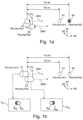
- FIGS. 1 a , 1 b , 1 c and 1 dshow a setup for forming a stereo image to a user.
- FIG. 1 aa situation is shown where a human being is viewing two spheres A 1 and A 2 using both eyes E 1 and E 2 .
- the sphere A 1is closer to the viewer than the sphere A 2 , the respective distances to the first eye E 1 being LE E1,A1 and LE E1,A2 .
- the different objectsreside in space at their respective (x,y,z) coordinates, defined by the coordinate system SZ, SY and SZ.
- the distance d 12 between the eyes of a human beingmay be approximately 62-64 mm on average, and varying from person to person between 55 and 74 mm.
- the viewing directions (optical axes) DIR 1 and DIR 2are typically essentially parallel, possibly having a small deviation from being parallel, and define the field of view for the eyes.
- the head of the userhas an orientation (head orientation) in relation to the surroundings, most easily defined by the common direction of the eyes when the eyes are looking straight ahead. That is, the head orientation tells the yaw, pitch and roll of the head in respect of a coordinate system of the scene where the user is.
- the spheres A 1 and A 2are in the field of view of both eyes.
- the center-point O 12 between the eyes and the spheresare on the same line. That is, from the center-point, the sphere A 2 is behind the sphere A 1 .
- each eyesees part of sphere A 2 from behind A 1 , because the spheres are not on the same line of view from either of the eyes.
- FIG. 1 bthere is a setup shown, where the eyes have been replaced by cameras C 1 and C 2 , positioned at the location where the eyes were in FIG. 1 a .
- the distances and directions of the setupare otherwise the same.
- the purpose of the setup of FIG. 1 bis to be able to take a stereo image of the spheres A 1 and A 2 .
- the two images resulting from image captureare F C1 and F C2 .
- the “left eye” image F C1shows the image SA 2 of the sphere A 2 partly visible on the left side of the image S A1 of the sphere A 1 .
- the “right eye” image F C2shows the image S A2 of the sphere A 2 partly visible on the right side of the image S A1 of the sphere A 1 .
- This difference between the right and left imagesis called disparity, and this disparity, being the basic mechanism with which the human visual system determines depth information and creates a 3D view of the scene, can be used to create an illusion of a 3D image.
- FIG. 1 cthe creating of this 3D illusion is shown.
- the images F C1 and F C2 captured by the cameras C 1 and C 2are displayed to the eyes E 1 and E 2 , using displays D 1 and D 2 , respectively.
- the disparity between the imagesis processed by the human visual system so that an understanding of depth is created. That is, when the left eye sees the image S A2 of the sphere A 2 on the left side of the image S A1 of sphere A 1 , and respectively the right eye sees the image of A 2 on the right side, the human visual system creates an understanding that there is a sphere V 2 behind the sphere V 1 in a three-dimensional world.
- the images F C1 and F C2can also be synthetic, that is, created by a computer. If they carry the disparity information, synthetic images will also be seen as three-dimensional by the human visual system. That is, a pair of computer-generated images can be formed so that they can be used as a stereo image.
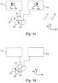
- FIG. 1 dillustrates how the principle of displaying stereo images to the eyes can be used to create 3D movies or virtual reality scenes having an illusion of being three-dimensional.
- the images F X1 and F X2are either captured with a stereo camera or computed from a model so that the images have the appropriate disparity.
- a large numbere.g. 30
- the human visual systemwill create a cognition of a moving, three-dimensional image.
- the camerais turned, or the direction of view with which the synthetic images are computed is changed, the change in the images creates an illusion that the direction of view is changing, that is, the viewer is rotating.
- This direction of viewmay be determined as a real orientation of the head e.g. by an orientation detector mounted on the head, or as a virtual orientation determined by a control device such as a joystick or mouse that can be used to manipulate the direction of view without the user actually moving his head.
- a control devicesuch as a joystick or mouse that can be used to manipulate the direction of view without the user actually moving his head.
- the term “head orientation”may be used to refer to the actual, physical orientation of the user's head and changes in the same, or it may be used to refer to the virtual direction of the user's view that is determined by a computer program or a computer input device.
- FIG. 2 ashows a system and apparatuses for stereo viewing, that is, for 3D video and 3D audio digital capture and playback.
- the task of the systemis that of capturing sufficient visual and auditory information from a specific location such that a convincing reproduction of the experience, or presence, of being in that location can be achieved by one or more viewers physically located in different locations and optionally at a time later in the future.
- Such reproductionrequires more information than can be captured by a single camera or microphone, in order that a viewer can determine the distance and location of objects within the scene using their eyes and their ears.
- two camera sourcesare used to create a pair of images with disparity.
- the human auditory systemIn a similar manned, for the human auditory system to be able to sense the direction of sound, at least two microphones are used (the commonly known stereo sound is created by recording two audio channels). The human auditory system can detect the cues e.g. in timing difference of the audio signals to detect the direction of sound.
- the system of FIG. 2 amay consist of three main parts: image sources, a server and a rendering device.
- a video capture device SRC 1comprises multiple (for example, 8) cameras CAM 1 , CAM 2 , . . . , CAMN with overlapping field of view so that regions of the view around the video capture device is captured from at least two cameras.
- the device SRC 1may comprise multiple microphones to capture the timing and phase differences of audio originating from different directions.
- the devicemay comprise a high resolution orientation sensor so that the orientation (direction of view) of the plurality of cameras can be detected and recorded.
- the device SRC 1comprises or is functionally connected to a computer processor PROC 1 and memory MEM 1 , the memory comprising computer program PROGR 1 code for controlling the capture device.
- the image stream captured by the devicemay be stored on a memory device MEM 2 for use in another device, e.g. a viewer, and/or transmitted to a server using a communication interface COMM 1 .
- one or more sources SRC 2 of synthetic imagesmay be present in the system.
- Such sources of synthetic imagesmay use a computer model of a virtual world to compute the various image streams it transmits.
- the source SRC 2may compute N video streams corresponding to N virtual cameras located at a virtual viewing position.
- the viewermay see a three-dimensional virtual world, as explained earlier for FIG. 1 d .
- the device SRC 2comprises or is functionally connected to a computer processor PROC 2 and memory MEM 2 , the memory comprising computer program PROGR 2 code for controlling the synthetic source device SRC 2 .
- the image stream captured by the devicemay be stored on a memory device MEMS (e.g. memory card CARD 1 ) for use in another device, e.g. a viewer, or transmitted to a server or the viewer using a communication interface COMM 2 .
- MEMSe.g. memory card CARD 1
- COMM 2communication interface
- a server SERVor a plurality of servers storing the output from the capture device SRC 1 or computation device SRC 2 .
- the devicecomprises or is functionally connected to a computer processor PROC 3 and memory MEM 3 , the memory comprising computer program PROGR 3 code for controlling the server.
- the servermay be connected by a wired or wireless network connection, or both, to sources SRC 1 and/or SRC 2 , as well as the viewer devices VIEWER 1 and VIEWER 2 over the communication interface COMM 3 .
- the viewer devicesmay have a rendering module and a display module, or these functionalities may be combined in a single device.
- the devicesmay comprise or be functionally connected to a computer processor PROC 4 and memory MEM 4 , the memory comprising computer program PROGR 4 code for controlling the viewing devices.
- the viewer (playback) devicesmay consist of a data stream receiver for receiving a video data stream from a server and for decoding the video data stream. The data stream may be received over a network connection through communications interface COMM 4 , or from a memory device MEM 6 like a memory card CARD 2 .
- the viewer devicesmay have a graphics processing unit for processing of the data to a suitable format for viewing as described with FIGS. 1 c and 1 d .
- the viewer VIEWER 1comprises a high-resolution stereo-image head-mounted display for viewing the rendered stereo video sequence.
- the head-mounted devicemay have an orientation sensor DET 1 and stereo audio headphones.
- the viewer VIEWER 2comprises a display enabled with 3D technology (for displaying stereo video), and the rendering device may have a head-orientation detector DET 2 connected to it.
- Any of the devices(SRC 1 , SRC 2 , SERVER, RENDERER, VIEWER 1 , VIEWER 2 ) may be a computer or a portable computing device, or be connected to such.
- Such rendering devicesmay have computer program code for carrying out methods according to various examples described in this text.
- FIG. 2 bshows a camera device for stereo viewing.
- the cameracomprises three or more cameras that are configured into camera pairs for creating the left and right eye images, or that can be arranged to such pairs.
- the distance between camerasmay correspond to the usual distance between the human eyes.
- the camerasmay be arranged so that they have significant overlap in their field-of-view. For example, wide-angle lenses of 180 degrees or more may be used, and there may be 3, 4, 5, 6, 7, 8, 9, 10, 12, 16 or 20 cameras.
- the camerasmay be regularly or irregularly spaced across the whole sphere of view, or they may cover only part of the whole sphere. For example, there may be three cameras arranged in a triangle and having a different directions of view towards one side of the triangle such that all three cameras cover an overlap area in the middle of the directions of view.
- 8 camerashaving wide-angle lenses and arranged regularly at the corners of a virtual cube and covering the whole sphere such that the whole or essentially whole sphere is covered at all directions by at least 3 or 4 cameras.
- FIG. 2 bthree stereo camera pairs are shown.
- FIG. 2 cshows a head-mounted display for stereo viewing.
- the head-mounted displaycontains two screen sections or two screens DISP 1 and DISP 2 for displaying the left and right eye images.
- the displaysare close to the eyes, and therefore lenses are used to make the images easily viewable and for spreading the images to cover as much as possible of the eyes' field of view.
- the deviceis attached to the head of the user so that it stays in place even when the user turns his head.
- the devicemay have an orientation detecting module ORDET 1 for determining the head movements and direction of the head. It is to be noted here that in this type of a device, tracking the head movement may be done, but since the displays cover a large area of the field of view, eye movement detection is not necessary.
- the head orientationmay be related to real, physical orientation of the user's head, and it may be tracked by a sensor for determining the real orientation of the user's head.
- head orientationmay be related to virtual orientation of the user's view direction, controlled by a computer program or by a computer input device such as a joystick. That is, the user may be able to change the determined head orientation with an input device, or a computer program may change the view direction (e.g. in gaming, the game program may control the determined head orientation instead or in addition to the real head orientation.
- FIG. 2 dillustrates a camera device CAM 1 .
- the camera devicehas a camera detector CAMDET 1 , comprising a plurality of sensor elements for sensing intensity of the light hitting the sensor element.
- the camera devicehas a lens OBJ 1 (or a lens arrangement of a plurality of lenses), the lens being positioned so that the light hitting the sensor elements travels through the lens to the sensor elements.
- the camera detector CAMDET 1has a nominal center point CP 1 that is a middle point of the plurality sensor elements, for example for a rectangular sensor the crossing point of the diagonals.
- the lenshas a nominal center point PP 1 , as well, lying for example on the axis of symmetry of the lens.
- the direction of orientation of the camerais defined by the half-line passing from the center point CP 1 of the camera sensor and the center point PP 1 of the lens.
- Time-synchronized video, audio and orientation datais first recorded with the capture device. This can consist of multiple concurrent video and audio streams as described above. These are then transmitted immediately or later to the storage and processing network for processing and conversion into a format suitable for subsequent delivery to playback devices. The conversion can involve post-processing steps to the audio and video data in order to improve the quality and/or reduce the quantity of the data while preserving the quality at a desired level.
- each playback devicereceives a stream of the data from the network, and renders it into a stereo viewing reproduction of the original location which can be experienced by a user with the head mounted display and headphones.
- the usermay be able to turn their head in multiple directions, and the playback device is able to create a high-frequency (e.g. 60 frames per second) stereo video and audio view of the scene corresponding to that specific orientation as it would have appeared from the location of the original recording.
- a high-frequency stereo video and audio view of the scenecorresponding to that specific orientation as it would have appeared from the location of the original recording.
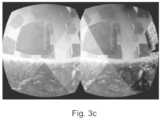
- FIGS. 3 a , 3 b and 3 cillustrate forming stereo images for first and second eye from image sources by using dynamic source selection and dynamic stitching location.
- image datafrom at least 2 different cameras is used.
- a single camerais not able to cover the whole field of view. Therefore, according to the present solution, multiple cameras may be used for creating both images for stereo viewing by stitching together sections of the images from different cameras.
- the image creation by stitchinghappens so that the images have an appropriate disparity so that a 3D view can be created. This will be explained in the following.
- a model of camera and eye positionsis used.
- the camerasmay have positions in the camera space, and the positions of the eyes are projected into this space so that the eyes appear among the cameras.
- a realistic parallaxdistance between the eyes
- the eyesmay be projected on the sphere, as well.
- the solutionfirst selects the closest camera to each eye. Head-mounted-displays can have a large field of view per eye such that there is no single image (from one camera) which covers the entire view of an eye.
- FIG. 3 ashows the two displays for stereo viewing.
- the image of the left eye displayis put together from image data from cameras IS 2 , IS 3 and IS 6 .
- the image of the right eye displayis put together from image data from cameras IS 1 , IS 3 and IS 8 .
- the same image source IS 3is in this example used for both the left eye and the right eye image, but this is done so that the same region of the view is not covered by camera IS 3 in both eyes. This ensures proper disparity across the whole view—that is, at each location in the view, there is a disparity between the left and right eye images.
- the stitching pointis changed dynamically for each head orientation to maximize the area around the central region of the view that is taken from the nearest camera to the eye position. At the same time, care is taken to ensure that different cameras are used for the same regions of the view in the two images for the different eyes.
- the regions PXA 1 and PXA 2 that correspond to the same area in the vieware taken from different cameras IS 1 and IS 2 , respectively. The two cameras are spaced apart, so the regions PXA 1 and PXA 2 show the effect of disparity, thereby creating a 3D illusion in the human visual system.
- STITCH 1 and STITCH 2are also avoided from being positioned in the center of the view, because the nearest camera will typically cover the area around the center.
- This methodleads to dynamic choosing of the pair of cameras to be used for creating the images for a certain region of the view depending on the head orientation. The choosing may be done for each pixel and each frame, using the detected head orientation.
- the stitchingis done with an algorithm ensuring that all stitched regions have proper stereo disparity.
- the left and right imagesare stitched together so that the objects in the scene continue across the areas from different camera sources. For example, the closest cube in the scene has been taken from one camera to the left eye image, and from two different cameras to the right eye view, and stitched together. There is a different camera used for all parts of the cube for the left and the right eyes, which creates disparity (the right side of the cube is more visible in the right eye image).
- the same camera imagemay be used partly in both left and right eyes but not for the same region.
- the right side of the left eye viewcan be stitched from camera IS 3 and the left side of the right eye can be stitched from the same camera IS 3 , as long as those view areas are not overlapping and different cameras (IS 1 and IS 2 ) are used for rendering those areas in the other eye.
- the same camera sourcein FIG. 3 a , IS 3 ) may be used in stereo viewing for both the left eye image and the right eye image.
- the left camerais used for the left image and the right camera is used for the right image.
- the present methodallows the source data to be utilized more fully.
- FIGS. 4 a and 4 billustrate a model for selecting the closest cameras for different head orientations.
- all sources(cameras) are arranged around a center point so that their positions form an octahedron and their distance from the center point is equal. This corresponds to an 8-camera device with regular inter-camera spacing.
- the sourceshave certain x, y and z coordinates in 3 d space.
- the sourcesare pointed directly away from the center point (orientation of sources is explained in context of FIG. 2 d ).
- the head-mounted devicereports roll, pitch and yaw of the viewer's head, and these may be used to transform the sources' coordinates in order to render them relatively to the head coordinate system.
- the coordinates of the eyesmay be transformed to the sources' coordinate system.
- the sources' coordinate systemmay be transformed to a normalized coordinate system, and the head coordinate system may be transformed to this same normalized coordinate system, too.
- both the sources and the eyesare positioned in the same model with respect to each other.
- locations of a first and a second virtual eye corresponding to said eyes of the userare determined in a coordinate system using the head orientation, and then the image sources are selected based on the locations of the virtual eyes with respect to image source locations in the coordinate system.
- R x( 1 0 0 0 cos ⁇ ⁇ ⁇ - sin ⁇ ⁇ ⁇ 0 sin ⁇ ⁇ ⁇ cos ⁇ ⁇ ⁇ ) .
- rotations R y (for yaw) and R z (for roll) around the different axescan be formed.
- All vectorsare vectors in three-dimensional space and described as (x, y, z).
- the originis in (0, 0, 0).
- All image sourceshave an orientation defined by yaw, pitch and roll around the origin.
- An imagined position of an eyeis positioned to equal distance from the center point than the cameras are, and rotated around the center point around all x, y and z axes according to the relative orientation of the viewer's head-mounted device compared to the capture device's orientation. As shown in FIGS. 4 a and 4 b , this results in the position of an imaginary middle eye MEYE in the middle of the face (corresponding to O 12 of FIG. 1 a ). The position of the viewer's imaginary middle eye is then rotated around the view's y-axis (aligned with the viewer's head, from the chin to the top of the head) to get the position of the virtual left eye LEYE or right eye REYE.
- the angle between the virtual left and right eyemay be between 80 and 120 degrees, e.g. approximately 100 degrees. Larger angles than 90 degrees may prevent picking of the same camera for the same region for both eyes, and smaller angles than 110 degrees may prevent cameras with too large inter-camera distance to be picked.
- the sourcesare the ordered according to the distance between the source and the virtual eye and the view is rendered so that pixels are picked from a source that, respectively: A) Covers that pixel B) Has the smallest distance to the virtual eye when compared against all the sources that fulfill condition A.
- an image source for a pixel of an image for a first eye of the useris determined to be a close image source that satisfies a closeness criterion (e.g. being the closest source) to a virtual eye corresponding to said first eye, where the close image source captures the scene portion corresponding to the pixel. If the close image source does not capture the scene portion corresponding to the pixel, an image source for a pixel of an image for the first eye of the user is selected to be another source than the close image source to said virtual eye corresponding to said first eye.
- FIGS. 4 c and 4 dillustrate selection of image sources for creation of stereo images when head orientation is changing.
- the pixelsare rendered from a source picked according to the following:
- Adjust the imagined person's eye disparityto make sure that the source is not the same for the left and the right eye, and that the picked sources have a disparity as close as possible to the human eyes (e.g. 64 mm).
- the amount of this adjustmentdepends on the available sources and their positions. The adjustment may be done beforehand, as well. If the closest camera for the first eye has been found e.g. 10 degrees lower in pitch than the first eye, the closest second eye may also be rotated 10 degrees lower in pitch. This may be done to at least in some cases avoid tilting (creating a roll) the parallax line between the cameras that would result from the other eye picking a camera that is higher in pitch.
- the virtual positionsmay be pre-mapped with a lookup table to closest camera lists, and the mapping may have a granularity e.g. 1 mm inside which all positions share the same list.
- a stencil buffermay be employed so that the pixels from the closest camera are rendered first and marked in the stencil buffer as rendered. Then, a stencil test is carried out to determine the non-rendered pixels that can be rendered from the next closest camera, the pixels from the next closest are rendered and marked, and so on, until the whole image has been rendered. That is, regions of an image for an eye are rendered so that the regions correspond to image sources, wherein the regions are rendered in order of closeness of the image sources to a virtual eye corresponding to said eye in image source coordinate system.
- the edge region of a cameramay be rendered using alpha channel rendering as follows. For each pixel, the (red-green-blue) color values of the pixel is computed from the source color values of source pixels, e.g. by interpolation or by using the color values of the closest source pixel. For most pixels, the alpha value (opaqueness) is one. For the pixels on the edge of the source, the alpha value may be set to less than one. This means that the color values from the next overlapping source and the earlier computed color values are mixed, creating a smoother stitch. For the edge areas, rendering may thus start from the furthest camera that covers the pixel. That is, regions of the images may be combined by blending the edge areas of the regions.
- FIGS. 4 c , 4 d and 4 eillustrate selection of image sources for creation of stereo images when head orientation is changing.
- the head orientation of the useris determined to obtain a first head orientation.
- a first image source (IS 7 ) and a second image source (IS 2 )are selected based on the first head orientation so that the first and second image source form a stereo image source, as has been explained above.
- IS 7a first image source
- IS 2second image source
- the scenethere may be understood to be a virtual region that corresponds to a certain detail of the scene.
- PXA 1 and PXA 2there is a corresponding region of pixels (PXA 1 and PXA 2 ) that represent the scene region.
- Color values of a first region of pixels (PXA 1 ) corresponding to a first region of a sceneare determined using the first image source (IS 7 ), and the color values of this first region of pixels are formed into the left eye image.
- Color values of a second region of pixels (PXA 2 ) corresponding to the same region of the sceneare formed using second image source (IS 2 ), and the color values of this second region of pixels are formed into the right eye image.
- the head orientation of the useris determined again to obtain a second head orientation. This may happen e.g. so that there is a head movement detector in the head-mounted display.
- image sourcesare again chosen, as shown in FIG. 4 d . Because the head has turned, the second image source (IS 2 ) and now a third image source (IS 8 ) are chosen based on the second head orientation, the second and third image source forming a stereo image source. This is done as explained above.
- Color values of a third region of pixels (PXA 3 ) corresponding to the first region of a sceneare formed using the third image source (IS 8 ), the color values of the third region of pixels (PXA 3 ) being formed into a third image for displaying to the left eye.
- Color values of a fourth region of pixels (PXA 4 ) corresponding to the same first region of a sceneare still formed using the second image source (IS 2 ), the color values of the fourth region of pixels being formed into a fourth image for displaying to the right eye.
- the detected or determined head orientationaffects the choosing of image sources that are used to form an image for an eye.
- the pair of image sources (cameras) used to create the stereo image of a region of a scenemay change from one time instance to another if the user turns his head or the camera view is rotated. This is because the same image source may not be the closest image source to the (virtual) eye at all times.
- the keyWhen reproducing a stereo view for a specific view orientation based on input from multiple cameras the key is to have parallax between the cameras. It has been noticed that this parallax however may cause a jump in the image region (and the disparity) between two successive frames when the camera pair for the image region changes due to a change in the viewing angle (head orientation). This jump can disturb the viewer and reduce the fidelity of the reproduction.
- the left imageis rendered from cameras IS 1 , IS 3 and IS 7
- the right imagefrom cameras IS 2 , IS 3 and IS 6 .
- IS 7one camera
- IS 8the camera change
- a technique used in this solutionis to cross-blend during multiple rendered frames between the two camera pairs, adjusting the timing and duration of the cross-blend according to the angular velocity of the viewing direction.
- the aimis to do the cross-blended jump when the viewing direction is changing rapidly as then there is natural motion blur already and the user is not focused on any specific point.
- the duration of the cross-blendmay also be adjusted according to the angular velocity so that in slow motion the cross-blend is done over longer period of time and in faster motion the cross-blend duration is shorter. This method reduces the visibility of the jump from a one camera pair to another.
- the cross-blendingcan be achieved by weighted summing of the affected image region values. For example, as shown in FIG.
- the area to be blendedmay be chosen to be the combined area of IS 7 and IS 8 .
- the areamay also be chosen to be the area of IS 8 only or IS 7 only.
- This methodhas been evaluated to reduce the noticeability of the jump from a camera pair to another, especially when viewed with a head mounted display.
- a temporal transitionmay be created by blending from an image formed using a first image source to an image using another image source.
- the duration of the temporal transition blendingmay be adjusted by using information on head movement speed, e.g. angular velocity.
- a hysteresis of changemay be applied.
- hysteresisit is meant that once a change in source from a first source to a second source has been applied due to a determination that the second source is closer to a virtual eye than the first source, a change back to the first source is not made as easily as the first change. That is, if the head orientation returns to the orientation right before the change, a change back to the first source is not affected. Change back to the first source needs a larger change in head orientation so that the first source is clearly closer to a virtual eye than the second source.
- Such a use of hysteresismay be used to prevent flickering caused by rapid switching of cameras back and forth at the orientation where the first and second sources are almost as close to the virtual eye.
- cross-blendingmay also happen so that the image sources for the whole area are changed, which results in the whole area to be cross-blended.
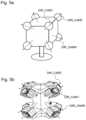
- FIGS. 5 a and 5 bshow an example of a camera device for being used as an image source.
- Every direction of viewneeds to be photographed from two locations, one for the left eye and one for the right eye.
- these imagesneed to be shot simultaneously to keep the eyes in sync with each other.
- one cameracannot physically cover the whole 360 degree view, at least without being obscured by another camera, there need to be multiple cameras to form the whole 360 degree panorama.
- Additional camerashowever increase the cost and size of the system and add more data streams to be processed. This problem becomes even more significant when mounting cameras on a sphere or platonic solid shaped arrangement to get more vertical field of view.
- the camera pairswill not achieve free angle parallax between the eye views.
- the parallax between eyesis fixed to the positions of the individual cameras in a pair, that is, in the perpendicular direction to the camera pair, no parallax can be achieved. This is problematic when the stereo content is viewed with a head mounted display that allows free rotation of the viewing angle around z-axis as well.
- a novel technique used in this solutionis to make use of lenses with a field of view of 180 degree (hemisphere) or greater and to arrange the cameras with a carefully selected arrangement around the capture device. Such an arrangement is shown in FIG. 5 a , where the cameras have been positioned at the corners of a virtual cube, having orientations DIR_CAM 1 , DIR_CAM 2 , . . . , DIR_CAMN essentially pointing away from the center point of the cube.
- Overlapping super wide field of view lensesmay be used so that a camera can serve both as the left eye view of a camera pair and as the right eye view of another camera pair. This reduces the amount of needed cameras to half.
- reducing the number of cameras in this mannerincreases the stereo viewing quality, because it also allows to pick the left eye and right eye cameras arbitrarily among all the cameras as long as they have enough overlapping view with each other.
- Using this technique with different number of cameras and different camera arrangementssuch as sphere and platonic solids enables picking the closest matching camera for each eye (as explained earlier) achieving also vertical parallax between the eyes. This is beneficial especially when the content is viewed using head mounted display.
- the described camera setup, together with the stitching technique described earliermay allow to create stereo viewing with higher fidelity and smaller expenses of the camera device.
- the wide field of viewallows image data from one camera to be selected as source data for different eyes depending on the current view direction, minimizing the needed number of cameras.
- the spacingcan be in a ring of 5 or more cameras around one axis in the case that high image quality above and below the device is not required, nor view orientations tilted from perpendicular to the ring axis.
- a platonic solid shapeIn case high quality images and free view tilt in all directions is required, a platonic solid shape must be used, either a cube (with 6 cameras), octahedron (with 8 cameras) or dodecahedron (with 12 cameras). Of these, the octahedron, or the corners of a cube ( FIG. 5 a ) is a good choice since it offers a good trade-off between minimizing the number of cameras while maximizing the number of camera-pairs combinations that are available for different view orientations.
- An actual camera device built with 8 camerasis shown in FIG. 5 b .
- the camera deviceuses 185-degree wide angle lenses, so that the total coverage of the cameras is more than 4 full spheres. This means that all points of the scene are covered by at least 4 cameras.
- the camerashave orientations DIR_CAM 1 , DIR_CAM 2 , . . . , DIR_CAMN pointing away from the center of the device.
- the camera devicemay comprise at least three cameras in a regular or irregular setting located in such a manner with respect to each other that any pair of cameras of said at least three cameras has a disparity for creating a stereo image having a disparity.
- the at least three camerashave overlapping fields of view such that an overlap region for which every part is captured by said at least three cameras is defined.
- Any pair of cameras of the at least three camerasmay have a parallax corresponding to parallax of human eyes for creating a stereo image.
- the parallax (distance) between the pair of camerasmay be between 5.0 cm and 12.0 cm, e.g. approximately 6.5 cm.
- the at least three camerasmay have different directions of optical axis.
- the overlap regionmay have a simply connected topology, meaning that it forms a contiguous surface with no holes, or essentially no holes so that the disparity can be obtained across the whole viewing surface, or at least for the majority of the overlap region.
- the field of view of each of said at least three camerasmay approximately correspond to a half sphere.
- the camera devicemay comprise three cameras, the three cameras being arranged in a triangular setting, whereby the directions of optical axes between any pair of cameras form an angle of less than 90 degrees.
- the at least three camerasmay comprise eight wide-field cameras positioned essentially at the corners of a virtual cube and each having a direction of optical axis essentially from the center point of the virtual cube to the corner in a regular manner, wherein the field of view of each of said wide-field cameras is at least 180 degrees, so that each part of the whole sphere view is covered by at least four cameras (see FIG. 5 b ).
- FIG. 5 cshows an example of a microphone device for being used as an audio source.
- a plurality of microphones MIC 1 , MIC 2 , MICNmay be positioned around the center of the device, regularly or irregularly. For example, there may be 8-20 microphones positioned on the surface of a virtual sphere.
- the capture devicemay include multiple microphones capturing the sound field at multiple locations and from all directions around the device. Similar to the video rendering, these source streams can be used to render (for example using a head-related transfer function) a synthetic audio signal similar to the one that would have been heard when the ear would have been located at the place in the scene dictated by the position of the viewer's head.
- a sound stream matching the position of the virtual earmay be created from the recordings of multiple microphones using multiple techniques.
- One techniqueis to choose a single original sound source closest to each virtual ear. However this gives spatial movement resolution limited to the original number of microphones.
- a better techniqueis to use well known audio beam-forming algorithms to combine the recordings from sets of 2 or more microphones and create synthetic intermediate audio streams corresponding to multiple focused lobes of space around the capture device. During rendering, these intermediate streams are then each filtered using a head-related transfer function (HRTF) corresponding to their current location relative to the virtual ear in a virtual head matching the current user head orientation, and then summed together to give a final simulated stream which matches more closely the stream that would have been heard by an ear at the same position as the virtual ear.
- HRTFhead-related transfer function
- a head-related transfer functionis a transfer function that tells how a sound from a point in space is heard by an ear.
- Two head-related transfer functions(for the left and right ear) can be used to form a stereo sound that appears to come from a certain direction and distance. Multiple sound sources from different directions and distances can be simply summed up to obtain the combined stereo sound from these sources.
- orientation correction used for video described belowis applied also to audio in order to optionally cancel out motion of the capture device if the viewer's head is not moving.
- the immersive experience of 3D content viewed with a head mounted displaycomes from how the user is able to look around by turning his head and the content is seen correctly according to the head orientation. If the capture device has moved while capturing (for example when mounted to a helmet of a scuba diver or to a branch of a tree) the movement will affect the viewing angle of the user independently of the viewer' s head orientation. This has been noticed to break the immersion and make it hard for the user to focus on a certain point or viewing angle.
- FIGS. 6 a and 6 bshow the use of source and destination coordinate systems for stereo viewing.
- a technique used hereis to record the capture device orientation synchronized with the overlapping video data, and use the orientation information to correct the orientation of the view presented to user—effectively cancelling out the rotation of the capture device during playback—so that the user is in control of the viewing direction, not the capture device. If the viewer instead wishes to experience the original motion of the capture device, the correction may be disabled. If the viewer wishes to experience a less extreme version of the original motion—the correction can be applied dynamically with a filter so that the original motion is followed but more slowly or with smaller deviations from the normal orientation.
- FIGS. 6 a and 6 billustrate the rotation of the camera device, and the rotation of the camera coordinate system (source coordinate system).
- the view and orientation of each camerais changing, as well, and consequently, even though the viewer stays in the same orientation as before, he will see a rotation to the left.
- the userwere to rotate his head to the left, the resulting view would turn even more heavily to the left, possibly changing the view direction by 180 degrees.
- the user's head movement(see FIGS. 6 c and 6 d ) will be the one controlling the view.
- the viewercan pick the objects to look at regardless of what the diver has been looking at. That is, the orientation of the image source is used together with the orientation of the head of the user to determine the images to be displayed to the user.
- FIGS. 7 a and 7 billustrate transmission of image source data for stereo viewing.
- the system of stereo viewing presented in this applicationmay employ multi-view video coding for transmitting the source video data to the viewer. That is, the server may have an encoder, or the video data may be in encoded form at the server, such that the redundancies in the video data are utilized for reduction of bandwidth.
- the coding efficiencymay be reduced.
- the different source signals V 1 -V 8may be combined to one video signal as in FIG. 7 a and transmitted as one coded video stream.
- the viewing devicemay then pick the pixel values it needs for rendering the images for the left and right eyes.
- the video data for the whole scenemay need to be transmitted (and/or decoded at the viewer), because during playback, the viewer needs to respond immediately to the angular motion of the viewer's head and render the content from the correct angle. To be able to do this the whole 360 degree panoramic video needs to be transferred from the server to the viewing device as the user may turn his head any time. This requires a large amount of data to be transferred that consumes bandwidth and requires decoding power.
- a technique used in this applicationis to report the current and predicted future viewing angle back to the server with view signaling and to allow the server to adapt the encoding parameters according to the viewing angle.
- the servercan transfer the data so that visible regions (active image sources) use more of the available bandwidth and have better quality, while using a smaller portion of the bandwidth (and lower quality) for the regions not currently visible or expected to visible shortly based on the head motion (passive image sources).
- thiswould mean that when a user quickly turns their head significantly, the content would at first have worse quality but then become better as soon as the server has received the new viewing angle and adapted the stream accordingly.
- An advantagemay be that while head movement is less, the image quality would be improved compared to the case of a static bandwidth allocation equally across the scene. This is illustrated in FIG. 7 b , where active source signals V 1 , V 2 , V 5 and V 7 are coded with better quality than the rest of the source signals (passive image sources) V 3 , V 4 , V 6 and V 8 .
- the servermay broadcast multiple streams where each have different area of the spherical panorama heavily compressed instead of one stream where everything is equally compressed.
- the viewing devicemay then choose according to the viewing angle which stream to decode and view. This way the server does not need to know about individual viewer's viewing angle and the content can be broadcast to any number of receivers.
- the image datamay be processed so that part of the spherical view is transferred in lower quality. This may be done at the server e.g. as a pre-processing step so that the computational requirements at transmission time are smaller
- the part of the view that's transferred in lower qualityis chosen so that it's not visible in the current viewing angle.
- the clientmay continuously report its viewing angle back to the server. At the same time the client can also send back other hints about the quality and bandwidth of the stream it wishes to receive.
- the servermay broadcast multiple streams where different parts of the view are transferred in lower quality and the client then selects the stream it decodes and views so that the lower quality area is outside the view with its current viewing angle.
- Some ways to lower the quality of a certain area of the spherical viewinclude for example:
- a stream that contains 8 sources in an octahedral arrangementcan reduce the bandwidth significantly by keeping the 4 sources intact that cover the current viewing direction completely (and more) and from the remaining 4 sources, drop 2 completely, and scale down the remaining two.
- the servercan update those two low quality sources only every other frame so that the compression algorithm can compress the unchanged sequential frames very tightly and also possibly set the compression's region of interest to cover only the 4 intact sources. By doing this the server manages to keep all the visible sources in high quality but significantly reduce the required bandwidth by making the invisible areas monoscopic, lower resolution, lower frame rate and more compressed.
- the clientwill adapt to the new viewing angle and select the stream(s) that have the new viewing angle in high quality, or in one-to-one streaming case the server will adapt the stream to provide high quality data for the new viewing angle and lower quality for the sources that are hidden.
- Synthetic 3D contentcan be rendered from the internal model of the scene using a graphics processing unit for interactive playback. Such an approach is common e.g. in computer games. However, the complexity and realism of such content is always limited by the amount of local processing power available, which is much less than would be available for non-live rendering.
- pre-rendering 3D films with computer-animated 3D contentare conventionally delivered with a fixed viewpoint encoded into pairs of stereo images. At best, the viewer can manually select a pair of his liking, although in a cinema environment, only one pair is available. These approaches do not have the interactive potential of the locally rendered content.
- FIG. 8illustrates the use of synthetic video sources in a virtual reality model for creating images for stereo viewing.
- a technique used in this applicationis to use the same method already described previously for capturing real-world content to pre-render, distribute and playback virtual content rendered by computers.
- a virtual camera device VCAMScomprising a plurality of cameras is positioned in the virtual world of the movie, and the action taking place is captured by the computer into video streams corresponding to the virtual cameras of the virtual camera device.
- the content delivered to a playerwould be generated synthetically in the same way as for a conventional 3D film, however including multiple camera views (more than 2) covering an entire sphere around the virtual viewer at least twice, and multiple audio streams allowing a realistic audio signal to be created for each viewer orientation.
- the internal three-dimensional (moving) model of the virtual worldis used to compute the image source images. Rendering the different objects OBJ 1 , OBJ 2 and OBJ 3 result in an image captured by a camera, and the computations are carried out for each camera. For example, 360 degree virtual cameras at the corners of a tetrahedron would provide similar overlap amount as the physical 8-camera device described earlier.
- the virtual camerasdo not obstruct each other in the same manner as real cameras, because virtual cameras can be made invisible in the virtual world. Therefore, the number of virtual cameras can be matched to be such that the viewer device can carry out rendering of the images.
- the wide-angle synthetic source signalsmay be decoded, and the stereo images of the synthetic world may be created by choosing the left and right eye source signals and possibly creating the images by the stitching method described earlier, if there is need for such stitching.
- the resultis that each viewer of this content can be inside the virtual world of the film, able to look in all directions, even while the film is paused.
- FIG. 9 ashows a flow chart of a method for forming images for stereo viewing.
- head orientation of a useris first determined in phase 910 to obtain a first head orientation.
- a first image source and a second image source basedare selected in 915 .
- These image sourcesare such that they form a stereo image source, that is, a stereo image created from images of these two sources would produce an understanding of a three-dimensional picture in the human visual system.
- a first stereo imageis created in 920 by rendering a first target image for one eye of the user using the first image source and a second target image for another eye of the user using the second image source.
- the image sourcesmay suffice for the whole first and second target images, or other image sources may also be used, as has been described earlier.
- Head orientation of the useris determined again to obtain a second head orientation in 930 .
- the same second image source and a new third image sourceare now selected based on the second head orientation in 935 .
- These image sourcesare such that they form a stereo image source, that is, a stereo image created from images of these two sources would produce an understanding of a three-dimensional picture in the human visual system.
- a second stereo imageis created by rendering a third target image for one eye of the user using the second image source and a fourth target image for another eye of the user using the third image source.
- FIG. 9 bshows a flow chart of a method for transmitting images for stereo viewing.
- a devicemay comprise circuitry and electronics for handling, receiving and transmitting data, computer program code in a memory, and a processor that, when running the computer program code, causes the device to carry out the features of an embodiment.
- a network devicelike a server may comprise circuitry and electronics for handling, receiving and transmitting data, computer program code in a memory, and a processor that, when running the computer program code, causes the network device to carry out the features of an embodiment.
Landscapes
- Engineering & Computer Science (AREA)
- Signal Processing (AREA)
- Multimedia (AREA)
- Physics & Mathematics (AREA)
- General Physics & Mathematics (AREA)
- Theoretical Computer Science (AREA)
- General Engineering & Computer Science (AREA)
- Optics & Photonics (AREA)
- Human Computer Interaction (AREA)
- Health & Medical Sciences (AREA)
- Audiology, Speech & Language Pathology (AREA)
- General Health & Medical Sciences (AREA)
- Testing, Inspecting, Measuring Of Stereoscopic Televisions And Televisions (AREA)
- Processing Or Creating Images (AREA)
- Stereoscopic And Panoramic Photography (AREA)
- Image Processing (AREA)
Abstract
Description
- i. show a setup for forming a stereo image to a user;
- i. illustrate forming stereo images for first and second eye from image sources;
- i. illustrate selection of image sources for creation of stereo images when head orientation is changing;
- i. show an example of a camera device for being used as an image source;
- i. show the use of source and destination coordinate systems for stereo viewing;
- i. illustrate transmission of image source data for stereo viewing;
- Create a position vector for the source and initialize it with (0, 0, 1)
- Make an identity transformation matrix
- Multiply the matrix by another that rotates coordinates around the y-axis by the amount of yaw
- Multiply the matrix by another that rotates coordinates around the x-axis by the amount of pitch
- Multiply the matrix by another that rotates coordinates around the z-axis by the amount of roll
- Transform the position vector with matrix multiplication using the matrix, the matrix applied from the left in the multiplication.
- Create a position vector for the eye and initialize it with (0, 0, 1)
- Take the view matrix that is used for rendering the sources according to the viewing direction (head orientation) and invert it. (To illustrate why the view matrix is inverted, for example when the viewing direction is rotated 10 degrees around y axis, the sources need to be rotated −10 degrees around y-axis. In a similar manner, if one looks at an object and rotates his head right, the object in your view moves to left. Therefore the rotation we apply to the imagined eye position may be taken as the inverse of the rotation we apply to the sources/view.)
- Rotate the inverted view matrix around the y-axis (the axis that points up in the head coordinate system) according to the simulated eye disparity (as described below).
- Transform the position vector according to the resulting matrix, with the matrix applied pre-vector.
- Calculate the distance between the eye position and the sources and pick the shortest distance (see below).
- Lowering the spatial resolution and/or scaling down the image data;
- Lowering color coding resolution or bit depth;
- Lowering the frame rate;
- Increasing the compression; and/or
- Dropping the additional sources for the pixel data and keeping only one source for the pixels, effectively making that region monoscopic instead of stereoscopic.
Claims (23)
Priority Applications (1)
| Application Number | Priority Date | Filing Date | Title |
|---|---|---|---|
| US15/431,279US11575876B2 (en) | 2014-04-07 | 2017-02-13 | Stereo viewing |
Applications Claiming Priority (6)
| Application Number | Priority Date | Filing Date | Title |
|---|---|---|---|
| GB1406201.2 | 2014-04-07 | ||
| GB1406201.2AGB2525170A (en) | 2014-04-07 | 2014-04-07 | Stereo viewing |
| GB1406201 | 2014-04-07 | ||
| PCT/FI2015/050184WO2015155406A1 (en) | 2014-04-07 | 2015-03-19 | Stereo viewing |
| US201615302123A | 2016-10-05 | 2016-10-05 | |
| US15/431,279US11575876B2 (en) | 2014-04-07 | 2017-02-13 | Stereo viewing |
Related Parent Applications (2)
| Application Number | Title | Priority Date | Filing Date |
|---|---|---|---|
| PCT/FI2015/050184ContinuationWO2015155406A1 (en) | 2014-04-07 | 2015-03-19 | Stereo viewing |
| US15/302,123ContinuationUS10455221B2 (en) | 2014-04-07 | 2015-03-19 | Stereo viewing |
Publications (2)
| Publication Number | Publication Date |
|---|---|
| US20170163970A1 US20170163970A1 (en) | 2017-06-08 |
| US11575876B2true US11575876B2 (en) | 2023-02-07 |
Family
ID=50776915
Family Applications (3)
| Application Number | Title | Priority Date | Filing Date |
|---|---|---|---|
| US15/302,123ActiveUS10455221B2 (en) | 2014-04-07 | 2015-03-19 | Stereo viewing |
| US15/431,279ActiveUS11575876B2 (en) | 2014-04-07 | 2017-02-13 | Stereo viewing |
| US15/430,779ActiveUS10645369B2 (en) | 2014-04-07 | 2017-02-13 | Stereo viewing |
Family Applications Before (1)
| Application Number | Title | Priority Date | Filing Date |
|---|---|---|---|
| US15/302,123ActiveUS10455221B2 (en) | 2014-04-07 | 2015-03-19 | Stereo viewing |
Family Applications After (1)
| Application Number | Title | Priority Date | Filing Date |
|---|---|---|---|
| US15/430,779ActiveUS10645369B2 (en) | 2014-04-07 | 2017-02-13 | Stereo viewing |
Country Status (13)
| Country | Link |
|---|---|
| US (3) | US10455221B2 (en) |
| EP (3) | EP3206398B1 (en) |
| JP (1) | JP2017518663A (en) |
| KR (1) | KR101885979B1 (en) |
| CN (1) | CN106165415B (en) |
| AU (1) | AU2015245446B2 (en) |
| CA (1) | CA2943856C (en) |
| GB (1) | GB2525170A (en) |
| MX (1) | MX369376B (en) |
| PH (1) | PH12016501960A1 (en) |
| RU (1) | RU2665872C2 (en) |
| WO (1) | WO2015155406A1 (en) |
| ZA (1) | ZA201607530B (en) |
Families Citing this family (73)
| Publication number | Priority date | Publication date | Assignee | Title |
|---|---|---|---|---|
| RU2543549C2 (en)* | 2013-07-09 | 2015-03-10 | Сергей Александрович Соболев | Television multiview method of acquiring, transmitting and receiving stereo information on monitored space with automatic measurement thereof "third eye" system |
| GB2525170A (en) | 2014-04-07 | 2015-10-21 | Nokia Technologies Oy | Stereo viewing |
| US10600245B1 (en) | 2014-05-28 | 2020-03-24 | Lucasfilm Entertainment Company Ltd. | Navigating a virtual environment of a media content item |
| TW201637432A (en)* | 2015-04-02 | 2016-10-16 | Ultracker Technology Co Ltd | Real-time image stitching device and real-time image stitching method |
| CN106612426B (en)* | 2015-10-26 | 2018-03-16 | 华为技术有限公司 | A kind of multi-view point video transmission method and device |
| TWI555378B (en)* | 2015-10-28 | 2016-10-21 | 輿圖行動股份有限公司 | An image calibration, composing and depth rebuilding method of a panoramic fish-eye camera and a system thereof |
| CN106657961B (en)* | 2015-10-30 | 2020-01-10 | 微软技术许可有限责任公司 | Hybrid digital-analog encoding of stereoscopic video |
| JP6384744B2 (en) | 2015-11-11 | 2018-09-05 | ソニー株式会社 | Encoding apparatus and encoding method |
| CN105915877A (en)* | 2015-12-27 | 2016-08-31 | 乐视致新电子科技(天津)有限公司 | Free film watching method and device of three-dimensional video |
| US20170195560A1 (en)* | 2015-12-31 | 2017-07-06 | Nokia Technologies Oy | Method and apparatus for generating a panoramic view with regions of different dimensionality |
| KR102360179B1 (en)* | 2016-02-02 | 2022-02-08 | 삼성전자주식회사 | 3D camera of capturing image for providing virtual reality |
| KR102381370B1 (en)* | 2016-02-19 | 2022-03-31 | 삼성전자주식회사 | VR device and image processing method for providing virtual reality |
| GB2547689A (en)* | 2016-02-26 | 2017-08-30 | Nokia Technologies Oy | A multi-camera device and a calibration method |
| GB2548860A (en)* | 2016-03-31 | 2017-10-04 | Nokia Technologies Oy | Multi-camera image coding |
| US10601889B1 (en)* | 2016-04-06 | 2020-03-24 | Ambarella International Lp | Broadcasting panoramic videos from one server to multiple endpoints |
| US10666941B1 (en)* | 2016-04-06 | 2020-05-26 | Ambarella International Lp | Low bitrate encoding of panoramic video to support live streaming over a wireless peer-to-peer connection |
| CN107316273B (en)* | 2016-04-27 | 2021-05-18 | 深圳看到科技有限公司 | Panoramic image acquisition device and acquisition method |
| US10757790B2 (en)* | 2016-06-10 | 2020-08-25 | Intel Corporation | Sensor hub apparatus and method for sensing ambient light and audio conditions |
| GB2551526A (en) | 2016-06-21 | 2017-12-27 | Nokia Technologies Oy | Image encoding method and technical equipment for the same |
| GB2556017A (en)* | 2016-06-21 | 2018-05-23 | Nokia Technologies Oy | Image compression method and technical equipment for the same |
| GB2556319A (en)* | 2016-07-14 | 2018-05-30 | Nokia Technologies Oy | Method for temporal inter-view prediction and technical equipment for the same |
| KR102317683B1 (en)* | 2016-07-28 | 2021-10-26 | 삼성전자주식회사 | Method and device for processing an image and recordimg medium thereof |
| CN109891850B (en)* | 2016-09-09 | 2023-04-04 | Vid拓展公司 | Method and apparatus for reducing 360 degree view adaptive streaming media delay |
| JP6732617B2 (en)* | 2016-09-21 | 2020-07-29 | 株式会社ソニー・インタラクティブエンタテインメント | Information processing apparatus and image generation method |
| WO2018067680A1 (en) | 2016-10-05 | 2018-04-12 | Hidden Path Entertainment, Inc. | System and method of capturing and rendering a stereoscopic panorama using a depth buffer |
| JP7128179B2 (en)* | 2016-10-21 | 2022-08-30 | マジック リープ, インコーポレイテッド | Systems and methods for presenting image content on multiple depth planes by providing multiple intra-pupillary suggestive views |
| GB2555139A (en)* | 2016-10-21 | 2018-04-25 | Nokia Technologies Oy | Detecting the presence of wind noise |
| GB2556910A (en)* | 2016-11-25 | 2018-06-13 | Nokia Technologies Oy | Virtual reality display |
| US10416757B2 (en)* | 2016-12-08 | 2019-09-17 | Raymond Maurice Smit | Telepresence system |
| US11636572B2 (en) | 2016-12-29 | 2023-04-25 | Nokia Technologies Oy | Method and apparatus for determining and varying the panning speed of an image based on saliency |
| US11836285B2 (en)* | 2017-03-10 | 2023-12-05 | Kenneth Perlin | System for a spectator to view a virtual reality of a performer and method |
| EP3603056A4 (en)* | 2017-03-22 | 2020-12-23 | Nokia Technologies Oy | METHOD, DEVICE AND COMPUTER PROGRAM PRODUCT FOR ADAPTIVE STREAMING |
| US10547704B2 (en)* | 2017-04-06 | 2020-01-28 | Sony Interactive Entertainment Inc. | Predictive bitrate selection for 360 video streaming |
| WO2018199701A1 (en) | 2017-04-28 | 2018-11-01 | Samsung Electronics Co., Ltd. | Method for providing content and apparatus therefor |
| KR102402046B1 (en)* | 2017-04-28 | 2022-05-26 | 삼성전자주식회사 | Method for providing content and apparatus therefor |
| CN110574369B (en)* | 2017-04-28 | 2021-08-03 | 三星电子株式会社 | Method and device for providing content |
| CN109327699B (en)* | 2017-07-31 | 2021-07-16 | 华为技术有限公司 | An image processing method, terminal and server |
| CN107491172B (en)* | 2017-08-16 | 2020-10-09 | 歌尔科技有限公司 | Somatosensory data acquisition method, device and electronic device |
| US10818087B2 (en) | 2017-10-02 | 2020-10-27 | At&T Intellectual Property I, L.P. | Selective streaming of immersive video based on field-of-view prediction |
| US11303814B2 (en)* | 2017-11-09 | 2022-04-12 | Qualcomm Incorporated | Systems and methods for controlling a field of view |
| US11087527B2 (en)* | 2017-12-01 | 2021-08-10 | Koninklijke Kpn N.V. | Selecting an omnidirectional image for display |
| CN111527749A (en)* | 2017-12-20 | 2020-08-11 | 镭亚股份有限公司 | Cross-rendering multi-view camera, system, and method |
| US10623725B2 (en)* | 2018-01-03 | 2020-04-14 | Votanic Ltd. | 3D glasses incorporating real-time tracking |
| EP3509308A1 (en)* | 2018-01-05 | 2019-07-10 | Koninklijke Philips N.V. | Apparatus and method for generating an image data bitstream |
| CN111670577A (en)* | 2018-02-09 | 2020-09-15 | 索尼公司 | Image processing apparatus, image processing method, and image processing program |
| US10659815B2 (en) | 2018-03-08 | 2020-05-19 | At&T Intellectual Property I, L.P. | Method of dynamic adaptive streaming for 360-degree videos |
| KR102638415B1 (en) | 2018-03-22 | 2024-02-19 | 브이아이디 스케일, 인크. | Viewport dependent video streaming events |
| KR20190118040A (en) | 2018-04-09 | 2019-10-17 | 삼성전자주식회사 | Wearable display apparatus and method of displaying 3-dimensional images thereof |
| EP3576407A1 (en)* | 2018-05-31 | 2019-12-04 | Nokia Technologies Oy | Stereoscopic content |
| US10628957B2 (en)* | 2018-06-18 | 2020-04-21 | Google Llc | Vision-enhanced pose estimation |
| US10902556B2 (en) | 2018-07-16 | 2021-01-26 | Nvidia Corporation | Compensating for disparity variation when viewing captured multi video image streams |
| US10412361B1 (en)* | 2018-07-16 | 2019-09-10 | Nvidia Corporation | Generated stereoscopic video using zenith and nadir view perspectives |
| CN109040601B (en)* | 2018-09-05 | 2020-06-26 | 清华-伯克利深圳学院筹备办公室 | Multi-scale unstructured billion pixel VR panoramic photography system |
| CN109407828A (en)* | 2018-09-11 | 2019-03-01 | 上海科技大学 | One kind staring the point estimation method and system, storage medium and terminal |
| EP3629585A1 (en)* | 2018-09-25 | 2020-04-01 | Koninklijke Philips N.V. | Image synthesis |
| WO2020066008A1 (en)* | 2018-09-28 | 2020-04-02 | 株式会社ソニー・インタラクティブエンタテインメント | Image data output device, content creation device, content reproduction device, image data output method, content creation method, and content reproduction method |
| US10818077B2 (en)* | 2018-12-14 | 2020-10-27 | Canon Kabushiki Kaisha | Method, system and apparatus for controlling a virtual camera |
| DE102019101192A1 (en)* | 2019-01-17 | 2020-07-23 | Innogy Se | Camera system and home automation system with one camera system |
| EP3690822A1 (en)* | 2019-01-30 | 2020-08-05 | Koninklijke Philips N.V. | Image representation of a scene |
| CN113396311A (en)* | 2019-02-07 | 2021-09-14 | 麦克赛尔株式会社 | Composite incident/emission device |
| EP3931625B1 (en) | 2019-02-28 | 2024-09-18 | Magic Leap, Inc. | Display system and method for providing variable accommodation cues using multiple intra-pupil parallax views formed by light emitter arrays |
| US11627303B2 (en)* | 2019-07-09 | 2023-04-11 | Interaptix Inc. | System and method for corrected video-see-through for head mounted displays |
| US11336832B1 (en)* | 2019-08-30 | 2022-05-17 | Gopro, Inc. | Systems and methods for horizon leveling videos |
| US10893218B1 (en) | 2019-09-20 | 2021-01-12 | Gopro, Inc. | Systems and methods for generating panoramic visual content |
| US11301035B1 (en) | 2019-09-27 | 2022-04-12 | Apple Inc. | Method and device for video presentation |
| CN111061123B (en)* | 2019-12-25 | 2022-02-15 | 重庆特斯联智慧科技股份有限公司 | Rotary panoramic imaging system for tourist landscape display and use method |
| CN111294517B (en) | 2020-03-03 | 2021-12-17 | 荣耀终端有限公司 | Image processing method and mobile terminal |
| KR102777985B1 (en)* | 2020-05-20 | 2025-03-10 | 삼성전자주식회사 | Apparatus and method for generating image |
| US11622100B2 (en)* | 2021-02-17 | 2023-04-04 | flexxCOACH VR | 360-degree virtual-reality system for dynamic events |
| CN116016885A (en)* | 2021-10-21 | 2023-04-25 | 中兴通讯股份有限公司 | Image processing method, cloud server, VR terminal and storage medium |
| US11750930B1 (en) | 2022-03-17 | 2023-09-05 | Honeywell International Inc. | Panoramic vision system with parallax mitigation |
| US12167161B1 (en)* | 2022-09-13 | 2024-12-10 | Gopro, Inc. | Systems and methods for horizon leveling videos |
| US20240091964A1 (en)* | 2022-09-16 | 2024-03-21 | Sarcos Corp. | Multidirectional Sensing Array for Robot Perception |
Citations (72)
| Publication number | Priority date | Publication date | Assignee | Title |
|---|---|---|---|---|
| US3225651A (en) | 1964-11-12 | 1965-12-28 | Wallace A Clay | Methods of stereoscopic reproduction of images |
| JPH0646313A (en) | 1992-07-21 | 1994-02-18 | Fujita Corp | TV camera system |
| US5657073A (en) | 1995-06-01 | 1997-08-12 | Panoramic Viewing Systems, Inc. | Seamless multi-camera panoramic imaging with distortion correction and selectable field of view |
| US5684531A (en) | 1995-04-10 | 1997-11-04 | The United States Of America As Represented By The Administrator Of The National Aeronautics And Space Administration | Ranging apparatus and method implementing stereo vision system |
| US5703604A (en) | 1995-05-22 | 1997-12-30 | Dodeca Llc | Immersive dodecaherdral video viewing system |
| JPH11164326A (en) | 1997-11-26 | 1999-06-18 | Oki Electric Ind Co Ltd | Panorama stereo image generation display method and recording medium recording its program |
| US6055012A (en) | 1995-12-29 | 2000-04-25 | Lucent Technologies Inc. | Digital multi-view video compression with complexity and compatibility constraints |
| US6141034A (en) | 1995-12-15 | 2000-10-31 | Immersive Media Co. | Immersive imaging method and apparatus |
| WO2001079908A1 (en) | 1999-12-31 | 2001-10-25 | Yissum Research Development Company Of The Hebrew University Of Jerusalem | Stereo panoramic camera arrangements for recording panoramic images useful in a stereo panoramic image pair |
| JP2001351126A (en) | 2000-06-05 | 2001-12-21 | Square Co Ltd | Computer-readable recording medium with program of game recorded thereon, program of game and method/ device for processing game |
| US20020015522A1 (en) | 1994-12-29 | 2002-02-07 | Rogina Peter R. | Image transformation and synthesis methods |
| US20020046218A1 (en) | 1999-06-23 | 2002-04-18 | Scott Gilbert | System for digitally capturing and recording panoramic movies |
| WO2002044808A2 (en) | 2000-11-29 | 2002-06-06 | Rvc Llc | System and method for spherical stereoscopic photographing |
| JP2002171460A (en) | 2000-11-30 | 2002-06-14 | Sony Corp | Reproducing device |
| US6434265B1 (en)* | 1998-09-25 | 2002-08-13 | Apple Computers, Inc. | Aligning rectilinear images in 3D through projective registration and calibration |
| US20020118890A1 (en)* | 2001-02-24 | 2002-08-29 | Michael Rondinelli | Method and apparatus for processing photographic images |
| JP2002258423A (en) | 2001-02-28 | 2002-09-11 | Sony Corp | Image input device |
| JP2002354505A (en) | 2001-05-29 | 2002-12-06 | Vstone Kk | Stereoscopic system |
| US6529631B1 (en) | 1996-03-29 | 2003-03-04 | Sarnoff Corporation | Apparatus and method for optimizing encoding and performing automated steerable image compression in an image coding system using a perceptual metric |
| US20030067536A1 (en)* | 2001-10-04 | 2003-04-10 | National Research Council Of Canada | Method and system for stereo videoconferencing |
| US20030117488A1 (en) | 2001-08-10 | 2003-06-26 | Donald Pierce | Stereoscopic panoramic image capture device |
| JP2004072694A (en) | 2002-08-09 | 2004-03-04 | Sony Corp | Information providing system and method, information providing apparatus and method, recording medium, and program |
| US20040125222A1 (en) | 2002-12-30 | 2004-07-01 | Bradski Gary R. | Stacked semiconductor radiation sensors having color component and infrared sensing capability |
| WO2004068865A1 (en) | 2003-01-24 | 2004-08-12 | Micoy Corporation | Steroscopic panoramic image capture device |
| US20040227693A1 (en)* | 2003-05-14 | 2004-11-18 | Darwin Rambo | Integral eye-path alignment on telephony and computer video devices using two or more image sensing devices |
| US20040246333A1 (en)* | 2003-06-03 | 2004-12-09 | Steuart Leonard P. (Skip) | Digital 3D/360 degree camera system |
| US20050018911A1 (en)* | 2003-07-24 | 2005-01-27 | Eastman Kodak Company | Foveated video coding system and method |
| US20050138569A1 (en) | 2003-12-23 | 2005-06-23 | Baxter Brent S. | Compose rate reduction for displays |
| US7075553B2 (en) | 2001-10-04 | 2006-07-11 | Eastman Kodak Company | Method and system for displaying an image |
| US20070103558A1 (en) | 2005-11-04 | 2007-05-10 | Microsoft Corporation | Multi-view video delivery |
| US20080002262A1 (en)* | 2006-06-29 | 2008-01-03 | Anthony Chirieleison | Eye tracking head mounted display |
| US20080298674A1 (en) | 2007-05-29 | 2008-12-04 | Image Masters Inc. | Stereoscopic Panoramic imaging system |
| US20090096927A1 (en)* | 2007-10-15 | 2009-04-16 | Camp Jr William O | System and method for video coding using variable compression and object motion tracking |
| CN101414054A (en) | 2008-11-21 | 2009-04-22 | 浙江大学 | Device and method for implementing stereo imaging by overall view ring belt imaging lens |
| RU2375840C2 (en) | 2007-04-19 | 2009-12-10 | Владимир Семенович Леонов | Method of forming three-dimensional colour virtual video image and device for creating effect of reality for user (versions) |
| US20100080291A1 (en) | 2006-12-13 | 2010-04-01 | Tomoyuki Yamamoto | Moving picture encoding apparatus and moving picture decoding apparatus |
| US20100220215A1 (en) | 2009-01-12 | 2010-09-02 | Jorge Rubinstein | Video acquisition and processing systems |
| US20100238262A1 (en) | 2009-03-23 | 2010-09-23 | Kurtz Andrew F | Automated videography systems |
| US7850306B2 (en) | 2008-08-28 | 2010-12-14 | Nokia Corporation | Visual cognition aware display and visual data transmission architecture |
| US20110187706A1 (en) | 2010-01-29 | 2011-08-04 | Vesely Michael A | Presenting a View within a Three Dimensional Scene |
| US20110229012A1 (en)* | 2010-03-22 | 2011-09-22 | Amit Singhal | Adjusting perspective for objects in stereoscopic images |
| CN102318374A (en) | 2009-02-13 | 2012-01-11 | 皇家飞利浦电子股份有限公司 | Head tracking |
| WO2012021129A1 (en) | 2010-08-10 | 2012-02-16 | Sony Computer Entertainment Inc. | 3d rendering for a rotated viewer |
| US20120147139A1 (en) | 2010-03-19 | 2012-06-14 | Bo Li | Stereoscopic image aligning apparatus, stereoscopic image aligning method, and program of the same |
| US20120224642A1 (en) | 2011-03-04 | 2012-09-06 | Ati Technologies Ulc | Method and system for providing single view video signal based on a multiview video coding (mvc) signal stream |
| WO2012136388A1 (en) | 2011-04-08 | 2012-10-11 | Fraunhofer-Gesellschaft zur Förderung der angewandten Forschung e.V. | Capturing panoramic or semi-panoramic 3d scenes |
| CN102819179A (en) | 2011-06-09 | 2012-12-12 | 财团法人金属工业研究发展中心 | Single-camera panoramic stereo imaging system |
| US20120320979A1 (en) | 2011-06-16 | 2012-12-20 | Axis Ab | Method and digital video encoder system for encoding digital video data |
| WO2012177378A2 (en) | 2011-06-20 | 2012-12-27 | Google Inc. | Systems and methods for adaptive transmission of data |
| WO2013015148A1 (en) | 2011-07-27 | 2013-01-31 | オリンパス株式会社 | Image processing system, information processing device, program, and image processing method |
| WO2013022296A2 (en) | 2011-08-09 | 2013-02-14 | 삼성전자 주식회사 | Multiview video data encoding method and device, and decoding method and device |
| US20130050412A1 (en)* | 2011-08-24 | 2013-02-28 | Sony Computer Entertainment Inc. | Image processing apparatus and image processing method |
| GB2494940A (en)* | 2011-09-23 | 2013-03-27 | Gixia Group Co | Head-mounted display with display orientation lock-on |
| US20130125155A1 (en) | 2010-07-26 | 2013-05-16 | Thomson Licensing | Dynamic adaptation of displayed video quality based on viewers' context |
| US20130135446A1 (en) | 2011-11-28 | 2013-05-30 | Hon Hai Precision Industry Co., Ltd. | Street view creating system and method thereof |
| US20130176403A1 (en) | 2011-08-16 | 2013-07-11 | Kenneth Varga | Heads up display (HUD) sensor system |
| US20130185353A1 (en) | 2010-07-14 | 2013-07-18 | Alcatel Lucent | Method, server and terminal for generating a composite view from multiple content items |
| US8493390B2 (en) | 2010-12-08 | 2013-07-23 | Sony Computer Entertainment America, Inc. | Adaptive displays using gaze tracking |
| US8502860B2 (en) | 2009-09-29 | 2013-08-06 | Toyota Motor Engineering & Manufacturing North America (Tema) | Electronic control system, electronic control unit and associated methodology of adapting 3D panoramic views of vehicle surroundings by predicting driver intent |
| US20130201296A1 (en) | 2011-07-26 | 2013-08-08 | Mitchell Weiss | Multi-camera head |
| US20130222590A1 (en)* | 2012-02-27 | 2013-08-29 | Honeywell International Inc. | Methods and apparatus for dynamically simulating a remote audiovisual environment |
| JP2013183209A (en) | 2012-02-29 | 2013-09-12 | Nagoya Univ | System and method for viewing multi-viewpoint video stream |
| CN103323948A (en) | 2012-03-23 | 2013-09-25 | 索尼公司 | Head-mounted display |
| US20130258044A1 (en) | 2012-03-30 | 2013-10-03 | Zetta Research And Development Llc - Forc Series | Multi-lens camera |
| CN103380625A (en) | 2011-06-16 | 2013-10-30 | 松下电器产业株式会社 | Head-mounted display and its position deviation adjustment method |
| EP2685707A1 (en) | 2012-07-12 | 2014-01-15 | Virtualmind di Davide Angelelli | System for spherical video shooting |
| US20140104424A1 (en) | 2012-10-11 | 2014-04-17 | GM Global Technology Operations LLC | Imaging surface modeling for camera modeling and virtual view synthesis |
| US20140118562A1 (en) | 2012-11-01 | 2014-05-01 | Microsoft Corporation | Video data |
| US20140168478A1 (en) | 2012-12-13 | 2014-06-19 | Qualcomm Incorporated | Text Image Quality Based Feedback For Improving OCR |
| US20140267596A1 (en)* | 2013-03-14 | 2014-09-18 | Joergen Geerds | Camera system |
| WO2015155406A1 (en) | 2014-04-07 | 2015-10-15 | Nokia Technologies Oy | Stereo viewing |
| US20160205341A1 (en) | 2013-08-20 | 2016-07-14 | Smarter Tv Ltd. | System and method for real-time processing of ultra-high resolution digital video |
Family Cites Families (4)
| Publication number | Priority date | Publication date | Assignee | Title |
|---|---|---|---|---|
| BR0317392A (en)* | 2002-12-19 | 2005-12-20 | Pharmacia Corp | Non-hygroscopic formulation including a hygroscopic drug |
| US8164524B2 (en)* | 2009-07-27 | 2012-04-24 | Auden Techno Corp. | Built-in straight mobile antenna type dual band antenna assembly with improved HAC performance |
| EP2689394A1 (en)* | 2011-03-22 | 2014-01-29 | Analogic Corporation | Compound object separation |
| JP6122260B2 (en)* | 2012-07-09 | 2017-04-26 | キヤノン株式会社 | Image processing apparatus and method and program thereof |
- 2014
- 2014-04-07GBGB1406201.2Apatent/GB2525170A/ennot_activeWithdrawn
- 2015
- 2015-03-19EPEP17164124.4Apatent/EP3206398B1/enactiveActive
- 2015-03-19EPEP15777524.8Apatent/EP3130143B1/enactiveActive
- 2015-03-19EPEP17164118.6Apatent/EP3206397B1/enactiveActive
- 2015-03-19KRKR1020167030907Apatent/KR101885979B1/enactiveActive
- 2015-03-19RURU2016141397Apatent/RU2665872C2/enactive
- 2015-03-19CACA2943856Apatent/CA2943856C/enactiveActive
- 2015-03-19CNCN201580018687.4Apatent/CN106165415B/enactiveActive
- 2015-03-19USUS15/302,123patent/US10455221B2/enactiveActive
- 2015-03-19JPJP2016561358Apatent/JP2017518663A/enactivePending
- 2015-03-19MXMX2016012988Apatent/MX369376B/enactiveIP Right Grant
- 2015-03-19AUAU2015245446Apatent/AU2015245446B2/enactiveActive
- 2015-03-19WOPCT/FI2015/050184patent/WO2015155406A1/enactiveApplication Filing
- 2016
- 2016-10-03PHPH12016501960Apatent/PH12016501960A1/enunknown
- 2016-11-01ZAZA2016/07530Apatent/ZA201607530B/enunknown
- 2017
- 2017-02-13USUS15/431,279patent/US11575876B2/enactiveActive
- 2017-02-13USUS15/430,779patent/US10645369B2/enactiveActive
Patent Citations (82)
| Publication number | Priority date | Publication date | Assignee | Title |
|---|---|---|---|---|
| US3225651A (en) | 1964-11-12 | 1965-12-28 | Wallace A Clay | Methods of stereoscopic reproduction of images |
| JPH0646313A (en) | 1992-07-21 | 1994-02-18 | Fujita Corp | TV camera system |
| US20020110275A1 (en) | 1994-12-29 | 2002-08-15 | Peter Rogina | Image transformation and synthesis methods |
| US20020015522A1 (en) | 1994-12-29 | 2002-02-07 | Rogina Peter R. | Image transformation and synthesis methods |
| US5684531A (en) | 1995-04-10 | 1997-11-04 | The United States Of America As Represented By The Administrator Of The National Aeronautics And Space Administration | Ranging apparatus and method implementing stereo vision system |
| US5703604A (en) | 1995-05-22 | 1997-12-30 | Dodeca Llc | Immersive dodecaherdral video viewing system |
| US5657073A (en) | 1995-06-01 | 1997-08-12 | Panoramic Viewing Systems, Inc. | Seamless multi-camera panoramic imaging with distortion correction and selectable field of view |
| US6141034A (en) | 1995-12-15 | 2000-10-31 | Immersive Media Co. | Immersive imaging method and apparatus |
| US6055012A (en) | 1995-12-29 | 2000-04-25 | Lucent Technologies Inc. | Digital multi-view video compression with complexity and compatibility constraints |
| US6529631B1 (en) | 1996-03-29 | 2003-03-04 | Sarnoff Corporation | Apparatus and method for optimizing encoding and performing automated steerable image compression in an image coding system using a perceptual metric |
| JPH11164326A (en) | 1997-11-26 | 1999-06-18 | Oki Electric Ind Co Ltd | Panorama stereo image generation display method and recording medium recording its program |
| US6434265B1 (en)* | 1998-09-25 | 2002-08-13 | Apple Computers, Inc. | Aligning rectilinear images in 3D through projective registration and calibration |
| US20020046218A1 (en) | 1999-06-23 | 2002-04-18 | Scott Gilbert | System for digitally capturing and recording panoramic movies |
| WO2001079908A1 (en) | 1999-12-31 | 2001-10-25 | Yissum Research Development Company Of The Hebrew University Of Jerusalem | Stereo panoramic camera arrangements for recording panoramic images useful in a stereo panoramic image pair |
| JP2001351126A (en) | 2000-06-05 | 2001-12-21 | Square Co Ltd | Computer-readable recording medium with program of game recorded thereon, program of game and method/ device for processing game |
| WO2002044808A2 (en) | 2000-11-29 | 2002-06-06 | Rvc Llc | System and method for spherical stereoscopic photographing |
| JP2004514951A (en) | 2000-11-29 | 2004-05-20 | アールヴイシー エルエルシー | Spherical stereoscopic imaging system and method |
| JP2002171460A (en) | 2000-11-30 | 2002-06-14 | Sony Corp | Reproducing device |
| US20020118890A1 (en)* | 2001-02-24 | 2002-08-29 | Michael Rondinelli | Method and apparatus for processing photographic images |
| JP2002258423A (en) | 2001-02-28 | 2002-09-11 | Sony Corp | Image input device |
| JP2002354505A (en) | 2001-05-29 | 2002-12-06 | Vstone Kk | Stereoscopic system |
| US20030117488A1 (en) | 2001-08-10 | 2003-06-26 | Donald Pierce | Stereoscopic panoramic image capture device |
| WO2003030535A1 (en) | 2001-10-04 | 2003-04-10 | National Research Council Of Canada | Method and system for stereo videoconferencing |
| US20030067536A1 (en)* | 2001-10-04 | 2003-04-10 | National Research Council Of Canada | Method and system for stereo videoconferencing |
| US7075553B2 (en) | 2001-10-04 | 2006-07-11 | Eastman Kodak Company | Method and system for displaying an image |
| JP2004072694A (en) | 2002-08-09 | 2004-03-04 | Sony Corp | Information providing system and method, information providing apparatus and method, recording medium, and program |
| US20040125222A1 (en) | 2002-12-30 | 2004-07-01 | Bradski Gary R. | Stacked semiconductor radiation sensors having color component and infrared sensing capability |
| WO2004068865A1 (en) | 2003-01-24 | 2004-08-12 | Micoy Corporation | Steroscopic panoramic image capture device |
| US20040227693A1 (en)* | 2003-05-14 | 2004-11-18 | Darwin Rambo | Integral eye-path alignment on telephony and computer video devices using two or more image sensing devices |
| WO2004109385A2 (en) | 2003-06-03 | 2004-12-16 | Steuart Leonard P Iii | Digital 3d/360 degree camera system |
| US20040246333A1 (en)* | 2003-06-03 | 2004-12-09 | Steuart Leonard P. (Skip) | Digital 3D/360 degree camera system |
| US20050018911A1 (en)* | 2003-07-24 | 2005-01-27 | Eastman Kodak Company | Foveated video coding system and method |
| US20050138569A1 (en) | 2003-12-23 | 2005-06-23 | Baxter Brent S. | Compose rate reduction for displays |
| US20070103558A1 (en) | 2005-11-04 | 2007-05-10 | Microsoft Corporation | Multi-view video delivery |
| US20080002262A1 (en)* | 2006-06-29 | 2008-01-03 | Anthony Chirieleison | Eye tracking head mounted display |
| US20100080291A1 (en) | 2006-12-13 | 2010-04-01 | Tomoyuki Yamamoto | Moving picture encoding apparatus and moving picture decoding apparatus |
| RU2375840C2 (en) | 2007-04-19 | 2009-12-10 | Владимир Семенович Леонов | Method of forming three-dimensional colour virtual video image and device for creating effect of reality for user (versions) |
| US20080298674A1 (en) | 2007-05-29 | 2008-12-04 | Image Masters Inc. | Stereoscopic Panoramic imaging system |
| US20090096927A1 (en)* | 2007-10-15 | 2009-04-16 | Camp Jr William O | System and method for video coding using variable compression and object motion tracking |
| WO2009151953A2 (en) | 2008-05-27 | 2009-12-17 | Image Masters, Inc. | Stereoscopic panoramic imaging system |
| US7850306B2 (en) | 2008-08-28 | 2010-12-14 | Nokia Corporation | Visual cognition aware display and visual data transmission architecture |
| CN101414054A (en) | 2008-11-21 | 2009-04-22 | 浙江大学 | Device and method for implementing stereo imaging by overall view ring belt imaging lens |
| US20100220215A1 (en) | 2009-01-12 | 2010-09-02 | Jorge Rubinstein | Video acquisition and processing systems |
| CN102318374A (en) | 2009-02-13 | 2012-01-11 | 皇家飞利浦电子股份有限公司 | Head tracking |
| US20100238262A1 (en) | 2009-03-23 | 2010-09-23 | Kurtz Andrew F | Automated videography systems |
| US8502860B2 (en) | 2009-09-29 | 2013-08-06 | Toyota Motor Engineering & Manufacturing North America (Tema) | Electronic control system, electronic control unit and associated methodology of adapting 3D panoramic views of vehicle surroundings by predicting driver intent |
| US20110187706A1 (en) | 2010-01-29 | 2011-08-04 | Vesely Michael A | Presenting a View within a Three Dimensional Scene |
| US20120147139A1 (en) | 2010-03-19 | 2012-06-14 | Bo Li | Stereoscopic image aligning apparatus, stereoscopic image aligning method, and program of the same |
| US20110229012A1 (en)* | 2010-03-22 | 2011-09-22 | Amit Singhal | Adjusting perspective for objects in stereoscopic images |
| US20130185353A1 (en) | 2010-07-14 | 2013-07-18 | Alcatel Lucent | Method, server and terminal for generating a composite view from multiple content items |
| US20130125155A1 (en) | 2010-07-26 | 2013-05-16 | Thomson Licensing | Dynamic adaptation of displayed video quality based on viewers' context |
| WO2012021129A1 (en) | 2010-08-10 | 2012-02-16 | Sony Computer Entertainment Inc. | 3d rendering for a rotated viewer |
| US8493390B2 (en) | 2010-12-08 | 2013-07-23 | Sony Computer Entertainment America, Inc. | Adaptive displays using gaze tracking |
| US20120224642A1 (en) | 2011-03-04 | 2012-09-06 | Ati Technologies Ulc | Method and system for providing single view video signal based on a multiview video coding (mvc) signal stream |
| WO2012136388A1 (en) | 2011-04-08 | 2012-10-11 | Fraunhofer-Gesellschaft zur Förderung der angewandten Forschung e.V. | Capturing panoramic or semi-panoramic 3d scenes |
| US20140104378A1 (en) | 2011-04-08 | 2014-04-17 | Fraunhofer-Gesellschaft Zur Foerderung Der Angewandten Forschung E.V. | Capturing panoramic or semi-panoramic 3d scenes |
| CN102819179A (en) | 2011-06-09 | 2012-12-12 | 财团法人金属工业研究发展中心 | Single-camera panoramic stereo imaging system |
| CN103380625A (en) | 2011-06-16 | 2013-10-30 | 松下电器产业株式会社 | Head-mounted display and its position deviation adjustment method |
| US20120320979A1 (en) | 2011-06-16 | 2012-12-20 | Axis Ab | Method and digital video encoder system for encoding digital video data |
| WO2012177378A2 (en) | 2011-06-20 | 2012-12-27 | Google Inc. | Systems and methods for adaptive transmission of data |
| US20130201296A1 (en) | 2011-07-26 | 2013-08-08 | Mitchell Weiss | Multi-camera head |
| WO2013015148A1 (en) | 2011-07-27 | 2013-01-31 | オリンパス株式会社 | Image processing system, information processing device, program, and image processing method |
| WO2013022296A2 (en) | 2011-08-09 | 2013-02-14 | 삼성전자 주식회사 | Multiview video data encoding method and device, and decoding method and device |
| US20140192155A1 (en) | 2011-08-09 | 2014-07-10 | Samsung Electronics Co., Ltd. | Multiview video data encoding method and device, and decoding method and device |
| US20130176403A1 (en) | 2011-08-16 | 2013-07-11 | Kenneth Varga | Heads up display (HUD) sensor system |
| US20130050412A1 (en)* | 2011-08-24 | 2013-02-28 | Sony Computer Entertainment Inc. | Image processing apparatus and image processing method |
| GB2494940A (en)* | 2011-09-23 | 2013-03-27 | Gixia Group Co | Head-mounted display with display orientation lock-on |
| US20130135446A1 (en) | 2011-11-28 | 2013-05-30 | Hon Hai Precision Industry Co., Ltd. | Street view creating system and method thereof |
| US20130222590A1 (en)* | 2012-02-27 | 2013-08-29 | Honeywell International Inc. | Methods and apparatus for dynamically simulating a remote audiovisual environment |
| JP2013183209A (en) | 2012-02-29 | 2013-09-12 | Nagoya Univ | System and method for viewing multi-viewpoint video stream |
| CN103323948A (en) | 2012-03-23 | 2013-09-25 | 索尼公司 | Head-mounted display |
| US20130258044A1 (en) | 2012-03-30 | 2013-10-03 | Zetta Research And Development Llc - Forc Series | Multi-lens camera |
| EP2685707A1 (en) | 2012-07-12 | 2014-01-15 | Virtualmind di Davide Angelelli | System for spherical video shooting |
| US20140104424A1 (en) | 2012-10-11 | 2014-04-17 | GM Global Technology Operations LLC | Imaging surface modeling for camera modeling and virtual view synthesis |
| US20140118562A1 (en) | 2012-11-01 | 2014-05-01 | Microsoft Corporation | Video data |
| US20140168478A1 (en) | 2012-12-13 | 2014-06-19 | Qualcomm Incorporated | Text Image Quality Based Feedback For Improving OCR |
| US20140267596A1 (en)* | 2013-03-14 | 2014-09-18 | Joergen Geerds | Camera system |
| US20160205341A1 (en) | 2013-08-20 | 2016-07-14 | Smarter Tv Ltd. | System and method for real-time processing of ultra-high resolution digital video |
| WO2015155406A1 (en) | 2014-04-07 | 2015-10-15 | Nokia Technologies Oy | Stereo viewing |
| AU2015245446A1 (en) | 2014-04-07 | 2016-09-22 | Nokia Technologies Oy | Stereo viewing |
| US20170118458A1 (en) | 2014-04-07 | 2017-04-27 | Nokia Technologies Oy | Stereo viewing |
| US20170155884A1 (en) | 2014-04-07 | 2017-06-01 | Nokia Technologies Oy | Stereo viewing |
Non-Patent Citations (56)
| Title |
|---|
| "Meet The Crazy Camera That Can Make Movies for the Oculus Rift", Gizmodo, Retrieved on Mar. 6, Webpage available at : http://gizmodo.com/meet-the-crazy-camera-that-could-make-movies-for-the-oc-1557318674. |
| "Panocam 3d : Panoramic 3d Camera", Oculus VR Forums, Retrieved on Mar. 6, Webpage available at : https://forums.oculus.com/vip/discussion/4984/panocam-3d-panoramic-3d-camera. |
| "Wide-Angle Stereo Photography", Accessorizing Your Stereo Camera, Retrieved on Mar. 6, Webpage available at : http://www.lhup.edu/˜dsimanek/3d/stereo/3dgallery19.htm. |
| Advisory Action for U.S. Appl. No. 15/302,123 dated Oct. 30, 2018. |
| Couture et al., "Panoramic Stereo Video Textures", IEEE International Conference on Computer Vision, Nov. 5-13, 2011, 8 pages. |
| Couture et al., "Perception of Blending in Stereo Motion Panoramas", ACM Transactions on Applied Perception, vol. 2, No. 3, May 2010, 10 pages. |
| Decision to Grant European Application No. 17164118.6 dated Dec. 12, 2019, 2 pages. |
| Decision to Grant for European Application No. 17164124.4 dated Jun. 27, 2019, 2 pages. |
| Ekmekcioglu et al., "Content Aware delivery of Visual Attention Based Scalable Multi-View Video Over P2P", 19th International Packet Video Workshop, May 10-11, 2012, pp. 71-76. |
| Extended European Search Report received for corresponding European Patent Application No. 15777524.8, dated Nov. 24, 2017, 10 pages. |
| Extended European Search Report received for corresponding European Patent Application No. 17164118.6, dated Jun. 8, 2017, 7 pages. |
| Extended European Search Report received for corresponding European Patent Application No. 17164124.4, dated Jun. 2, 2017, 7 pages. |
| Final Office action received for corresponding Russian Patent Application No. 2016141397, dated Nov. 28, 2017, 18 pages of office action and 11 pages of translation available. |
| Final Office action received for corresponding U.S. Appl. No. 15/302,123, dated Jul. 17, 2018, 15 pages. |
| Intention to Grant for European Application No. 15 777 524.8 dated Feb. 2, 2019, 5 pages. |
| Intention to Grant for European Application No. 17 164 118.6 dated Aug. 5, 2019, 6 pages. |
| Intention to Grant for European Application No. 17 164 124.4 dated Mar. 25, 2019, 5 pages. |
| International Search Report and Written Opinion received for corresponding Patent Cooperation Treaty Application No. PCT/FI2015/050184, dated Jul. 9, 2015, 21 pages. |
| Mavlankar et al., "Video Streaming With Interactive Pan/Tilt/Zoom", High-Quality Visual Experience Signals and Communication Technology, 2010, pp. 1-26. |
| Non-Final Office action received for corresponding U.S. Appl. No. 15/302,123, dated Feb. 5, 2018, 14 pages. |
| Non-Final Office action received for corresponding U.S. Appl. No. 15/430,779, dated Jul. 31, 2018, 9 pages. |
| Notice of Allowance for U.S. Appl. No. 15/302,123 dated Jun. 11, 2019. |
| Notice of Allowance for U.S. Appl. No. 15/430,779 dated Dec. 30, 2019. |
| Notice of the Result of Substantive Examination for Indonesian Application No. P00201607272 dated Feb. 26, 2020, 4 pages. |
| Office Action for Canadian Application No. 2,943,856 dated Feb. 7, 2019, 5 pages. |
| Office Action for Chinese Application No. 201580018687 dated Mar. 17, 2020, 19 pages. |
| Office Action for Chinese Application No. 2015800186874 dated Jun. 13, 2019, 17 pages. |
| Office Action for Chinese Application No. 2015800186874 dated Nov. 28, 2018, 6 pages. |
| Office Action for European Application No. 17 164 118.6 dated Feb. 11, 2019, 4 pages. |
| Office Action for European Application No. 17 164 118.6 dated Sep. 25, 2018, 4 pages. |
| Office Action for European Application No. 17 164 124.4 dated Sep. 25, 2018, 4 pages. |
| Office Action for India Application No. 201647037329 dated Mar. 16, 2020, 7 pages. |
| Office Action for Indonesia Application No. P00201607272 dated Aug. 26, 2020, 5 pages. |
| Office Action for Japanese Application No. 2016-561358 dated Feb. 4, 2020, 17 pages. |
| Office Action for Japanese Application No. 2016-561358 dated Oct. 16, 2018, 5 pages. |
| Office Action for Mexican Application No. MX/a/2016/012988 dated May 22, 2019, 6 pages. |
| Office Action for Philippine Application No. 1/2016/501960 dated May 17, 2021, 7 pages. |
| Office Action for Philippine Application No. 1/2016/501960 dated Nov. 22, 2021, 3 pages. |
| Office Action for Philippine Application No. 1/2016/501960 dated Sep. 10, 2020, 3 pages. |
| Office Action for U.S. Appl. No. 15/302,123 dated Jan. 9, 2019. |
| Office Action for U.S. Appl. No. 15/430,779 dated Aug. 27, 2019. |
| Office Action for U.S. Appl. No. 15/430,779 dated Jan. 28, 2019, 12 pages. |
| Office Action for Vietnam Application No. 1-2016-03961 dated Aug. 14, 2020, 4 pages. |
| Office action received for corresponding Australian Patent Application No. 2015245446, dated Jul. 6, 2018, 4 pages. |
| Office action received for corresponding Canadian Patent Application No. 2943856, dated Jul. 11, 2017, 3 pages. |
| Office action received for corresponding Canadian Patent Application No. 2943856, dated May 25, 2018, 5 pages. |
| Office action received for corresponding Chinese Patent Application No. 201580018687.4, dated Jul. 7, 2017, 5 pages of office action and 3 pages of translation available. |
| Office action received for corresponding Chinese Patent Application No. 201580018687.4, dated Mar. 8, 2018, 7 pages of office action and 3 pages of translation available. |
| Office action received for corresponding Japanese Patent Application No. 2016-561358, dated Feb. 6, 2018, 4 pages of office action and 9 pages of translation available. |
| Office action received for corresponding Korean Patent Application No. 2016-7030907, dated Dec. 5, 2017, 4 pages of office action and no page of translation available. |
| Office action received for corresponding Vietnam Patent Application No. 1-2016-03961, dated Dec. 13, 2016, 1 pages of office action and 1 pages of office action translation available. |
| Richardt et al., "Megastereo: Constructing High-Resolution Stereo Panoramas", IEEE Conference on Computer Vision and Pattern Recognition, Jun. 23-28, 2013, pp. 1-8. |
| Search Report received for corresponding United Kingdom Patent Application No. 1406201.2, dated Mar. 3, 2015, 2 pages. |
| Search Report received for corresponding United Kingdom Patent Application No. 1406201.2, dated Oct. 15, 2014, 3 pages. |
| Summons to Attend Oral proceedings for European Application No. 15777524.8 dated Jul. 25, 2019, 4 pages. |
| Vivet et al., "Real-Time Stereo Mosaicing Using Feature Tracking", IEEE International Symposium on Multimedia, Dec. 5-7, 2011, pp. 577-582. |
Also Published As
| Publication number | Publication date |
|---|---|
| US10645369B2 (en) | 2020-05-05 |
| US20170118458A1 (en) | 2017-04-27 |
| RU2016141397A3 (en) | 2018-05-08 |
| CN106165415A (en) | 2016-11-23 |
| US20170155884A1 (en) | 2017-06-01 |
| EP3206398A1 (en) | 2017-08-16 |
| EP3130143B1 (en) | 2020-08-12 |
| PH12016501960A1 (en) | 2017-01-09 |
| EP3130143A1 (en) | 2017-02-15 |
| CA2943856C (en) | 2020-08-18 |
| MX369376B (en) | 2019-11-07 |
| EP3206397B1 (en) | 2020-01-08 |
| RU2016141397A (en) | 2018-05-08 |
| RU2665872C2 (en) | 2018-09-04 |
| AU2015245446A1 (en) | 2016-09-22 |
| MX2016012988A (en) | 2016-12-07 |
| CN106165415B (en) | 2020-12-04 |
| JP2017518663A (en) | 2017-07-06 |
| EP3130143A4 (en) | 2017-12-27 |
| AU2015245446B2 (en) | 2019-04-04 |
| CA2943856A1 (en) | 2015-10-15 |
| EP3206397A1 (en) | 2017-08-16 |
| GB201406201D0 (en) | 2014-05-21 |
| US10455221B2 (en) | 2019-10-22 |
| EP3206398B1 (en) | 2019-07-24 |
| US20170163970A1 (en) | 2017-06-08 |
| ZA201607530B (en) | 2019-04-24 |
| GB2525170A (en) | 2015-10-21 |
| KR101885979B1 (en) | 2018-08-06 |
| KR20160143746A (en) | 2016-12-14 |
| WO2015155406A1 (en) | 2015-10-15 |
Similar Documents
| Publication | Publication Date | Title |
|---|---|---|
| US11575876B2 (en) | Stereo viewing | |
| US20170227841A1 (en) | Camera devices with a large field of view for stereo imaging | |
| US10257492B2 (en) | Image encoding and display | |
| US10306202B2 (en) | Image encoding and display | |
| US10631008B2 (en) | Multi-camera image coding | |
| US20210185299A1 (en) | A multi-camera device and a calibration method | |
| GB2568241A (en) | Content generation apparatus and method | |
| WO2018109265A1 (en) | A method and technical equipment for encoding media content | |
| WO2018109266A1 (en) | A method and technical equipment for rendering media content | |
| GB2548080A (en) | A method for image transformation | |
| HK1233091B (en) | Stereo viewing | |
| WO2019043288A1 (en) | A method, device and a system for enhanced field of view |
Legal Events
| Date | Code | Title | Description |
|---|---|---|---|
| AS | Assignment | Owner name:NOKIA TECHNOLOGIES OY, FINLAND Free format text:ASSIGNMENT OF ASSIGNORS INTEREST;ASSIGNORS:BALDWIN, ANDREW ROBERT;GRONHOLM, KIM;SIGNING DATES FROM 20140408 TO 20150324;REEL/FRAME:041241/0550 | |
| STPP | Information on status: patent application and granting procedure in general | Free format text:FINAL REJECTION MAILED | |
| STPP | Information on status: patent application and granting procedure in general | Free format text:RESPONSE AFTER FINAL ACTION FORWARDED TO EXAMINER | |
| STPP | Information on status: patent application and granting procedure in general | Free format text:ADVISORY ACTION MAILED | |
| STPP | Information on status: patent application and granting procedure in general | Free format text:DOCKETED NEW CASE - READY FOR EXAMINATION | |
| STPP | Information on status: patent application and granting procedure in general | Free format text:NON FINAL ACTION MAILED | |
| STPP | Information on status: patent application and granting procedure in general | Free format text:RESPONSE TO NON-FINAL OFFICE ACTION ENTERED AND FORWARDED TO EXAMINER | |
| STPP | Information on status: patent application and granting procedure in general | Free format text:FINAL REJECTION MAILED | |
| STPP | Information on status: patent application and granting procedure in general | Free format text:DOCKETED NEW CASE - READY FOR EXAMINATION | |
| STPP | Information on status: patent application and granting procedure in general | Free format text:NON FINAL ACTION MAILED | |
| STPP | Information on status: patent application and granting procedure in general | Free format text:RESPONSE TO NON-FINAL OFFICE ACTION ENTERED AND FORWARDED TO EXAMINER | |
| STPP | Information on status: patent application and granting procedure in general | Free format text:FINAL REJECTION MAILED | |
| STPP | Information on status: patent application and granting procedure in general | Free format text:RESPONSE AFTER FINAL ACTION FORWARDED TO EXAMINER | |
| STPP | Information on status: patent application and granting procedure in general | Free format text:ADVISORY ACTION MAILED | |
| STPP | Information on status: patent application and granting procedure in general | Free format text:DOCKETED NEW CASE - READY FOR EXAMINATION | |
| STPP | Information on status: patent application and granting procedure in general | Free format text:NON FINAL ACTION MAILED | |
| STPP | Information on status: patent application and granting procedure in general | Free format text:RESPONSE TO NON-FINAL OFFICE ACTION ENTERED AND FORWARDED TO EXAMINER | |
| STPP | Information on status: patent application and granting procedure in general | Free format text:NOTICE OF ALLOWANCE MAILED -- APPLICATION RECEIVED IN OFFICE OF PUBLICATIONS | |
| STPP | Information on status: patent application and granting procedure in general | Free format text:PUBLICATIONS -- ISSUE FEE PAYMENT RECEIVED | |
| STPP | Information on status: patent application and granting procedure in general | Free format text:PUBLICATIONS -- ISSUE FEE PAYMENT VERIFIED | |
| STPP | Information on status: patent application and granting procedure in general | Free format text:AWAITING TC RESP, ISSUE FEE PAYMENT VERIFIED | |
| STCF | Information on status: patent grant | Free format text:PATENTED CASE |