US11575449B2 - Communication unit for an electrical machine tool, electrical machine tool system and method - Google Patents
Communication unit for an electrical machine tool, electrical machine tool system and methodDownload PDFInfo
- Publication number
- US11575449B2 US11575449B2US15/760,761US201615760761AUS11575449B2US 11575449 B2US11575449 B2US 11575449B2US 201615760761 AUS201615760761 AUS 201615760761AUS 11575449 B2US11575449 B2US 11575449B2
- Authority
- US
- United States
- Prior art keywords
- electric motor
- electric
- power tool
- acoustic signal
- tool
- Prior art date
- Legal status (The legal status is an assumption and is not a legal conclusion. Google has not performed a legal analysis and makes no representation as to the accuracy of the status listed.)
- Active, expires
Links
- 238000004891communicationMethods0.000titleclaimsabstractdescription32
- 238000000034methodMethods0.000titleclaimsdescription9
- 239000004065semiconductorSubstances0.000claimsdescription3
- 230000005540biological transmissionEffects0.000abstractdescription27
- 230000005236sound signalEffects0.000description10
- 230000001960triggered effectEffects0.000description8
- 230000008901benefitEffects0.000description6
- 238000012937correctionMethods0.000description2
- 230000000694effectsEffects0.000description2
- 230000006870functionEffects0.000description2
- 238000011022operating instructionMethods0.000description2
- 230000001133accelerationEffects0.000description1
- 230000006978adaptationEffects0.000description1
- 239000004020conductorSubstances0.000description1
- 238000013440design planningMethods0.000description1
- 238000011161developmentMethods0.000description1
- 238000009499grossingMethods0.000description1
- 230000002452interceptive effectEffects0.000description1
- 238000004519manufacturing processMethods0.000description1
- 230000006855networkingEffects0.000description1
- 230000010355oscillationEffects0.000description1
- 230000000737periodic effectEffects0.000description1
- 238000012360testing methodMethods0.000description1
- 238000011144upstream manufacturingMethods0.000description1
Images

Classifications
- H—ELECTRICITY
- H04—ELECTRIC COMMUNICATION TECHNIQUE
- H04B—TRANSMISSION
- H04B11/00—Transmission systems employing sonic, ultrasonic or infrasonic waves
- B—PERFORMING OPERATIONS; TRANSPORTING
- B25—HAND TOOLS; PORTABLE POWER-DRIVEN TOOLS; MANIPULATORS
- B25F—COMBINATION OR MULTI-PURPOSE TOOLS NOT OTHERWISE PROVIDED FOR; DETAILS OR COMPONENTS OF PORTABLE POWER-DRIVEN TOOLS NOT PARTICULARLY RELATED TO THE OPERATIONS PERFORMED AND NOT OTHERWISE PROVIDED FOR
- B25F5/00—Details or components of portable power-driven tools not particularly related to the operations performed and not otherwise provided for
- B—PERFORMING OPERATIONS; TRANSPORTING
- B25—HAND TOOLS; PORTABLE POWER-DRIVEN TOOLS; MANIPULATORS
- B25B—TOOLS OR BENCH DEVICES NOT OTHERWISE PROVIDED FOR, FOR FASTENING, CONNECTING, DISENGAGING OR HOLDING
- B25B21/00—Portable power-driven screw or nut setting or loosening tools; Attachments for drilling apparatus serving the same purpose
Definitions
- the disclosurerelates to a communication facility for an electric power tool, in particular a hand-held power tool, which has at least one electric actuator and a control unit for triggering the electric actuator, comprising a transmission facility, assigned to the power tool, for transmitting data, and comprising a receiving facility, assigned to a mobile or stationary facility, for receiving the data.
- the disclosureadditionally relates to an electric tool system for such an electric tool, and to a method for operating a communication facility or an electric tool as described above.
- Communication facilities of the type mentioned at the outsetare known from the prior art.
- Power toolsin particular hand-held power tools, are usually understood to be stand-alone appliances that themselves provide all control and information functions, such that the user can perform control inputs and read out information directly on the power tool.
- Due to the networking of products among one another by means of the so-called Internet of Thingsnew possibilities are being made available, by which it becomes possible for information to be output or controls to be input in a decentralized manner, i.e. separate from the power tool. For example, this enables the power tool to be remotely operated by an external, or separate, facility, or its operating status to be checked.
- Communication facilitieswhich use differing data transmission possibilities, are used for transmitting the data.
- communication facilitiesare known that transmit data wirelessly, by infrared or by visible light. Wired connections of communication facilities are also known.
- the communication facility according to the disclosurehas the advantage that means already present in the power tool are used for transmitting the data. Consequently, it is possible to dispense with the addition and design planning of an additional transmission facility.
- a particularly compact and inexpensive solutionis offered, by which it is possible to transmit data wirelessly from the power tool to the separate facility.
- the receiving facilityhas at least one microphone, and the control unit, together with the electric actuator, forms the transmission unit, and for the purpose of transmitting data triggers the electric actuator to generate an acoustic signal to be picked up by the microphone.
- the communication facilitythus uses the acoustic transmission of data.
- the control unittriggers the electric actuator in such a manner that the latter generates an audio signal, or one or more defined sounds, which can be picked up by the microphone of the receiving facility and evaluated.
- the transmission unit of the communication facilityis formed by the control unit and the electric actuator together. Consequently, elements that are already present in the power tool are used for data transmission. The result, that data of the electric power tool are transmitted acoustically, is achieved solely by the programming of the control unit for corresponding triggering of the electric actuator.
- the control unithas power electronics, having at least one switching element, in particular a power semiconductor switch, that can be actuated electrically.
- the power electronicsin particular the switching element
- the electric actuatoris easily triggered for the purpose of generating the sounds.
- the use of power semiconductor switchesrenders possible particularly rapid switching operations, which result in selective sound generation, such that a high resolution can be achieved in respect of the information content of the acoustic signal.
- the electric actuatoris realized as an electric motor.
- the control unitcan excite the electric motor, for example, to selectively generate acoustic information that can be picked up by the microphone of the receiving facility.
- a housing of the power toolis also used as an acoustic amplifier and/or conductor.
- the electric actuatoris an electric magnetic actuator that, for example, actuates a valve or the like. By appropriate triggering of this electric actuator, also, it is possible to selectively generate an acoustic signal that can be picked up by the microphone and evaluated.
- the electric tool system according to the disclosureis characterized by the communication facility according to the disclosure.
- the control unit and the electric actuator of the electric hand-held tooltogether form the transmission facility, and the mobile or stationary facility has the associated receiving facility, having a microphone.
- the facilityis realized as a mobile computer or mobile telephone. Consequently, the user, for example by running a corresponding program or application on their mobile telephone or mobile computer, can easily use the microphone of the mobile computer or mobile telephone, which is present in any case, to evaluate the sounds generated by the electric tool in order, for example, to receive and evaluate operating data of the electric tool.
- the method according to the disclosureis characterized in that, for the purpose of transmitting data, the electric actuator is triggered to generate an acoustic signal, which is picked up by the receiving facility and evaluated.
- the electric actuatoris triggered in such a manner that it generates sounds without actuation.
- Triggering without actuationin this context is to be understood to mean that the electric actuator, as a result of being triggered, does not execute the function actually assigned to it, such as, for example, actuating the valve or generating a torque, and instead merely generates a specific sound, or acoustic signal.
- the electric motoris triggered to generate the signal in such a manner that it is triggered without torque or rotation, i.e. it does not generate any torque or any rotation.
- the electric motorthus does not effect any actuation, e.g. driving of a tool. It is thereby ensured that, as a result of the transmission of the data, the power tool is in an operationally safe state and, in particular, no unwanted actuations are effected.
- the electric actuatoras an electric motor, is triggered by pulse-width modulation. This ensures simple and precise triggering of the electric motor, in particular for the purpose of generating the acoustic signal, or data, to be transmitted.
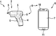
- FIG. 1an electric tool system, in a simplified representation
- FIG. 2a communication facility of the electric tool system, in a simplified representation
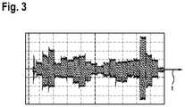
- FIG. 3an example of a signal transmitted by the communication facility.
- FIG. 1in a simplified representation, shows an electric tool system 1 , comprising an electric power tool 2 , which is realized as a hand-held power tool.
- the electric power tool 2has an electric actuator 3 in the form of an electric motor, and a control unit 4 which, in dependence on an actuation of an operating element 5 , triggers the electric actuator 3 to drive a tool receiver 5 in one of two directions of rotation.
- the electric tool system 1additionally has a facility 6 , realized as a mobile telephone, which is separate from the electric power tool 2 , and which has a touch-sensitive screen 7 for displaying information and for the input of control commands.
- the electric tool system 1additionally has a communication facility 8 , which has a transmission facility 9 , assigned to the electric power tool 2 , and a receiving facility 10 , assigned to the facility 6 .
- the receiving facility 10has a microphone 11 , in this case the microphone 11 of the mobile telephone 6 , which in normal operation is used to pick up speech.
- the transmission facility 9is formed by the control unit 4 and the electric motor.
- the control unit 4is designed to trigger the electric actuator 3 to transmit data, in such a manner that the latter generates one or more sounds to form an acoustic signal, without driving of the tool receiver 5 being effected in this case.
- the control unit 4triggers by pulse modulation, for example, power electronics 15 connected upstream from the electric motor in such a manner that puts the electric motor 3 into vibrational motion.
- the control unit 4triggers the electric motor in such a manner that, entirely without motion of its own, solely as a result of the electrical triggering, generates an acoustic signal that can be picked up by the microphone 11 of the receiving facility 10 . If the generated acoustic signal is sufficiently loud, the receiving facility 10 picks up the acoustic signal and evaluates it, in order to read out the data transmitted by the transmission facility 9 .
- FIG. 2shows the communication facility 8 , in a simplified partial view.
- the control unit 4has means or a facility 12 for acquiring current operating data of the electric power tool 2 .
- one or more temperature values of differing components of the electric power tool 2are acquired by means of the facility 12 .
- an existing current, a voltage or also an acceleration of the electric motorcan also read out, for example, a serial number, a machine type, an elapsed operating period, error messages or the like from a memory of the control unit 4 .
- the data acquired by the facility 12are, in particular, optionally or according to requirement, brought by an encoding facility 13 into a format that is suitable for data transmission by means of the transmission facility 9 . If necessary, the encoding may also be expanded by error correction.
- a facility 14prepares the formatted data, which exist, in particular, as a data packet, for acoustic transmission.
- the data packetis subjected to frequency shift keying (FSK).
- FSKfrequency shift keying
- the digital data to be transmittedis thereby brought into a form suitable for acoustic data transmission.
- a carrier frequency of a periodic sinusoidal oscillationis altered between a set of differing frequencies that represent the individual transmission symbols, or items of information.
- other modulation methodsmay also be used.
- the control unit 4triggers the power electronics 15 of the actuator 3 , or electric motor 16 .
- the power electronics 15in this case effects pulse-width modulated triggering of the electric motor 16 .
- the duty cycle of the pulse-width modulation in this caseis selected in such a manner that the electric motor 16 , on the one hand, does not begin to rotate and, on the other hand, generates an acoustic signal as previously described.
- the electric motor 16is excited to a motion that mechanically generates the acoustic signal as required.
- the electric motor 16may be triggered, for example, in such a manner that it vibrates instead of rotating.
- This mechanical motiongenerates sound waves, which are radiated directly or indirectly. If necessary, the sound waves are amplified by a housing of the electric power tool 2 .
- the sound wavesare represented in simplified form, as curved lines.
- the microphone 11 of the receiving facility 10picks up the sound waves, which reach the microphone 11 directly or indirectly, for example via an intermediate medium.
- a demodulation facility 17converts the acoustic signal back into digital data/values, which are translated or decoded by a decoding facility 18 and provided in readable form to a facility 19 .
- the facility 19may be, for example, a control unit of the mobile telephone 6 that displays the revealed data to the user via the screen 7 .
- the presented communication facility 8information can thus be transmitted wirelessly, by an acoustic signal, from the electric power tool 2 to the facility 6 , and displayed there.
- a loudspeaker facility for generating the acoustic signalis not provided. Instead, components already present in the electric power tool 2 are used to generate the acoustic signal.
- Any terminal device that has a microphone for picking up the acoustic signalmay be used to receive the data. It is thus possible, for example, for the user to load or install a corresponding application onto their mobile telephone, to enable them to read out information of their electric power tool 2 . For the user, this is also convenient and inexpensive.
- a transmitting audio signalis shown exemplarily in FIG. 3 .
- the communication facility 8works with a 32-letter alphabet. Each letter is represented by a different frequency of the audio signal.
- an audio signal, or a data transmissioncomprises 20 letters. These letters define the start of the audio signal, the data to be transmitted, and a correction error.
- other encodings of the audio signalmay also be used.
- the loudness of the audio signalincreases with the degree of pulse-width modulation.
- the duty factorbe low enough for the electric motor 16 not to be put into a rotational motion.
- the duty factorin this case is preferably determined in dependence on the inertia of the mechanical components of the electric power tool 2 that are to be driven. In the case of the present exemplary embodiment, with a hand-held screwdriver, a duty factor of 13%, for example, is advantageous.
- the audio signal shown in FIG. 3can advantageously be optimized in respect of its quality by increasing the duty factor and by generating a sinusoidal signal.
- the inductivity of the electric motor 16can be used in this case as a low-pass filer for smoothing steep pulse edges.
- the audio signalhas differing amplitudes for differing frequencies. This is due to the non-linearity of the electric motor 16 and the resonance of the housing of the electric power tool 2 . This can be improved by individually adapting the duty factor for each frequency.
- the communication facility 8may be used both with battery-operated and with cable-connected electric power tools. In the case in which the electric actuator 3 may be switched on and off at any time, frequency modulation represents a good choice for data transmission.
- the transmission facility 9may be used in almost any, in particular battery-operated, electric power tool 2 .
- the communication facility 8may be used, for example, at the end of the production line, to test the manufactured product. Furthermore, it is possible to use the communication facility to perform a product identification, for example to poll a product name, a software and/or hardware version, Furthermore, users may use the installed application to obtain further information about the electric power tool 2 , which is, for example, a display item in a store.
- the communication facility 8may also be used to easily read out faults of the electric power tool 2 and, for example, to forward these to a service centre. Moreover, data concerning the operation of the electric power tool 2 may be acquired continuously and used for market analysis. For this purpose, the data are transmitted, for example, directly from the mobile telephone to a central server, where the data can be collected and evaluated.
- the communication facility 8may also be used to generate warning signals, for example if the electric power tool 2 reaches a critical temperature, or is in danger of reaching a critical temperature, in which case the operation of the electric power tool 2 is then preferably adjusted automatically.
- the transmission facility 9may use differing acoustic signals to communicate differing events.
- the audio signalmay also be used to operate interactive operating instructions, such that, for example in the event of a fault, the electric tool uses a corresponding acoustic signal to guide the user to a particular page in the operating instructions that is relevant to the current fault.
- the electric power tool 2may also be identified by the communication facility 8 , and located by means of the mobile telephone.
- the transmission facilitycan transmit measured or calculated data, which may be used to calculate or estimate further values such as, for example, an estimated remaining operating time, the number of screws that have been screwed-in or that remain to be screwed-in, the charge state, voltage, temperature, the general state of a battery, and/or an estimated wait time after a fault, in particular a load.
- the electric power tool 2can transmit information to the user, the bandwidth of the information transmission advantageously being between 0.3 kHz and 3 kHz. It is also possible, by means of the communication facility 8 , for the electric power tool 2 to wirelessly trigger an accessory such as, for example, an ancillary unit that can be attached to the electric power tool 2 , by means of the acoustic signal.
- the headphone socket of the mobile telephonemay also be connected to a charging connection of the electric power tool 2 , if necessary with an interposed adapter.
- the control unitwhich in particular has a microcontroller, may be used as a digital amplifier.
- the electric motormay be used directly as a vibration loudspeaker, as described previously. Alternatively, however, the motor could also be connected to a loudspeaker facility in order, for example, to amplify the acoustic signal.
Landscapes
- Engineering & Computer Science (AREA)
- Mechanical Engineering (AREA)
- Computer Networks & Wireless Communication (AREA)
- Signal Processing (AREA)
- Control Of Electric Motors In General (AREA)
- Arrangements For Transmission Of Measured Signals (AREA)
- Portable Power Tools In General (AREA)
Abstract
Description
Claims (10)
Applications Claiming Priority (3)
| Application Number | Priority Date | Filing Date | Title |
|---|---|---|---|
| DE102015217826.9 | 2015-09-17 | ||
| DE102015217826.9ADE102015217826A1 (en) | 2015-09-17 | 2015-09-17 | Communication device for an electric machine tool, power tool system and method |
| PCT/EP2016/071037WO2017045980A1 (en) | 2015-09-17 | 2016-09-07 | Communication unit for an electrical machine tool, electrical machine tool system and method |
Publications (2)
| Publication Number | Publication Date |
|---|---|
| US20180331768A1 US20180331768A1 (en) | 2018-11-15 |
| US11575449B2true US11575449B2 (en) | 2023-02-07 |
Family
ID=56893962
Family Applications (1)
| Application Number | Title | Priority Date | Filing Date |
|---|---|---|---|
| US15/760,761Active2037-09-25US11575449B2 (en) | 2015-09-17 | 2016-09-07 | Communication unit for an electrical machine tool, electrical machine tool system and method |
Country Status (6)
| Country | Link |
|---|---|
| US (1) | US11575449B2 (en) |
| EP (1) | EP3349947B1 (en) |
| JP (1) | JP2018528870A (en) |
| CN (1) | CN108025428A (en) |
| DE (1) | DE102015217826A1 (en) |
| WO (1) | WO2017045980A1 (en) |
Cited By (1)
| Publication number | Priority date | Publication date | Assignee | Title |
|---|---|---|---|---|
| US20250236041A1 (en)* | 2021-10-08 | 2025-07-24 | Husqvarna Ab | Electric power tool |
Families Citing this family (6)
| Publication number | Priority date | Publication date | Assignee | Title |
|---|---|---|---|---|
| CN211178931U (en)* | 2017-04-10 | 2020-08-04 | Abb瑞士股份有限公司 | Motor condition monitoring device |
| DE102017222449A1 (en)* | 2017-12-12 | 2019-06-13 | Robert Bosch Gmbh | Measuring blind riveting tool and method for setting a blind rivet |
| US11621531B2 (en) | 2018-09-28 | 2023-04-04 | Hubbell Incorporated | Power tool with crimp localization |
| DE102018222694A1 (en) | 2018-12-21 | 2020-06-25 | Robert Bosch Gmbh | Hand tool |
| CN115917454A (en) | 2020-06-21 | 2023-04-04 | 哈勃股份有限公司 | Power tools with images of crimping |
| US20250153334A1 (en)* | 2022-01-31 | 2025-05-15 | Milwaukee Electric Tool Corporation | Identifying Power Tool Devices Based on Sound Generated by Electronic Components of the Power Tool Devices |
Citations (66)
| Publication number | Priority date | Publication date | Assignee | Title |
|---|---|---|---|---|
| US4001773A (en)* | 1973-09-12 | 1977-01-04 | American Petroscience Corporation | Acoustic telemetry system for oil wells utilizing self generated noise |
| US4314365A (en)* | 1980-01-21 | 1982-02-02 | Exxon Production Research Company | Acoustic transmitter and method to produce essentially longitudinal, acoustic waves |
| US4351029A (en)* | 1979-12-05 | 1982-09-21 | Westinghouse Electric Corp. | Tool life monitoring and tracking apparatus |
| US4642618A (en)* | 1985-07-23 | 1987-02-10 | Ibm Corporation | Tool failure detector |
| JPH04169000A (en) | 1990-10-31 | 1992-06-17 | Ricoh Co Ltd | Stepping motor drive device |
| US5166908A (en)* | 1990-07-16 | 1992-11-24 | Atlantic Richfield Company | Piezoelectric transducer for high speed data transmission and method of operation |
| US5307263A (en)* | 1992-11-17 | 1994-04-26 | Raya Systems, Inc. | Modular microprocessor-based health monitoring system |
| US5721546A (en)* | 1995-03-24 | 1998-02-24 | Mitsubishi Denki Kabushiki Kaisha | Encoder unit for providing to a servo motor control unit position data which is adjusted to account for processing delays |
| US5897493A (en)* | 1997-03-28 | 1999-04-27 | Health Hero Network, Inc. | Monitoring system for remotely querying individuals |
| US5899855A (en)* | 1992-11-17 | 1999-05-04 | Health Hero Network, Inc. | Modular microprocessor-based health monitoring system |
| CN1251793A (en) | 1998-10-16 | 2000-05-03 | 伊利诺斯工具公司 | Exhaust buffer for explosive driving tools, spring aided repositioner and silencer |
| US6211775B1 (en)* | 1998-06-15 | 2001-04-03 | Samsung Electro-Mechanics Co., Ltd. | Vibration apparatus capable of generating and externally transmitting a sound wave of audible frequency and transmitting a vibration for notification |
| EP1136188A2 (en) | 2000-03-16 | 2001-09-26 | Makita Corporation | Power impact tools with impact sound detecting means |
| JP2002267740A (en)* | 2001-03-12 | 2002-09-18 | Kazuhiro Watanabe | Tool with transmitter or receiver and its position detection system and work monitoring system |
| US20020177792A1 (en)* | 2001-05-28 | 2002-11-28 | Takafumi Ooba | Ultrasonic wave cosmetic device |
| US20030037423A1 (en)* | 2001-08-24 | 2003-02-27 | Siegel Robert P. | Intelligent power tool |
| US6696814B2 (en)* | 2001-07-09 | 2004-02-24 | Tyco Electronics Corporation | Microprocessor for controlling the speed and frequency of a motor shaft in a power tool |
| US6839660B2 (en)* | 2002-04-22 | 2005-01-04 | Csi Technology, Inc. | On-line rotating equipment monitoring device |
| US6845279B1 (en)* | 2004-02-06 | 2005-01-18 | Integrated Technologies, Inc. | Error proofing system for portable tools |
| DE202005017962U1 (en) | 2005-11-15 | 2006-03-02 | Hans Einhell Ag | Electrical hand tool, for drilling wall has metallic projection e.g. drill, pointing towards wall, which serves as antenna for detecting electromagnetic alternating signals transmitted by alternating field of conductor in wall |
| JP2006067726A (en) | 2004-08-27 | 2006-03-09 | Minebea Co Ltd | Motor state informing method and motor drive device |
| US20060074513A1 (en)* | 2004-09-28 | 2006-04-06 | Derose Lynn A | System and method for monitoring tool usage |
| US7054696B2 (en)* | 2002-07-18 | 2006-05-30 | Black & Decker Inc. | System and method for data retrieval in AC power tools via an AC line cord |
| US7065456B1 (en)* | 2004-08-19 | 2006-06-20 | Honda Motor Co., Ltd. | Tool monitoring system and method |
| US20070090788A1 (en)* | 2005-10-21 | 2007-04-26 | Hansford Brey D | System and method for recharging a battery exposed to a harsh environment |
| US7330129B2 (en)* | 2003-07-16 | 2008-02-12 | Black & Decker Inc. | System and method for data retrieval in AC power tools via an AC line cord |
| US7421426B2 (en)* | 2005-01-11 | 2008-09-02 | International Business Machines Corporation | Systems, methods, and media for utilizing electronic document usage information with search engines |
| US20080252446A1 (en)* | 2007-04-16 | 2008-10-16 | Credo Technology Corporation | Power hand tool with data collection and storage and method of operating |
| US20090040061A1 (en)* | 2007-03-17 | 2009-02-12 | Golunski Witold | Apparatus and system for monitoring tool use |
| JP2009083039A (en) | 2007-09-28 | 2009-04-23 | Panasonic Electric Works Co Ltd | Electric tool |
| CN101450476A (en) | 2007-12-04 | 2009-06-10 | C.&E.泛音有限公司 | Screwing tool and method for controlling the tightening angle of a threaded joint |
| US7590029B2 (en)* | 2005-02-24 | 2009-09-15 | The Charles Stark Draper Laboratory, Inc. | Methods and systems for communicating data through a pipe |
| US20090251330A1 (en)* | 2008-04-03 | 2009-10-08 | Hilti Aktiengesellschaft | Hand-held power tool |
| US7613590B2 (en)* | 1992-11-17 | 2009-11-03 | Health Hero Network, Inc. | Modular microprocessor-based power tool system |
| US20110049247A1 (en)* | 2008-02-08 | 2011-03-03 | Reactec Limited | Attachment arrangement |
| US20110275424A1 (en)* | 2010-05-07 | 2011-11-10 | Michael Schmid | Personal hygiene system |
| US8170800B2 (en)* | 2009-03-16 | 2012-05-01 | Verdande Technology As | Method and system for monitoring a drilling operation |
| CN102574281A (en) | 2009-10-23 | 2012-07-11 | 罗伯特·博世有限公司 | Protective sensor system for a hand-held power tool |
| US20120179077A1 (en)* | 2011-01-10 | 2012-07-12 | Tuck Cleve R | Vibrator apparatus with audio and motor control features |
| US20120318545A1 (en)* | 2011-06-16 | 2012-12-20 | Alfred Schreiber | Hand-Held Power Tool |
| US8406697B2 (en)* | 2009-02-24 | 2013-03-26 | Panasonic Electric Works Power Tools Co., Ltd. | Wireless communications system for tool |
| US8412179B2 (en)* | 2008-04-03 | 2013-04-02 | Hilti Aktiengesellschaft | Method of configuring power tool electronics in a hand-held power tool |
| CA2765605C (en)* | 2009-06-15 | 2013-10-22 | Xact Downhole Telemetry Inc. | Air hammer optimization using acoustic telemetry |
| US20140005820A1 (en) | 2012-06-29 | 2014-01-02 | Robert Bosch Gmbh | Controlling a battery-operated handheld power tool |
| WO2014198679A2 (en) | 2013-06-12 | 2014-12-18 | Atlas Copco Industrial Technique Ab | A method for diagnosing a torque impulse generator |
| DE102013211228A1 (en) | 2013-06-17 | 2014-12-18 | Robert Bosch Gmbh | Hand tool system |
| EP2868437A1 (en) | 2013-10-29 | 2015-05-06 | HILTI Aktiengesellschaft | Hand operated or semi stationary power tool or work device |
| US9256988B2 (en)* | 2012-09-11 | 2016-02-09 | Black & Decker Inc. | System and method for identifying a power tool |
| US20160175976A1 (en)* | 2014-12-18 | 2016-06-23 | Illinois Tool Works Inc. | Systems and methods for determining a weld torch location |
| US9756402B2 (en)* | 2015-05-04 | 2017-09-05 | Milwaukee Electric Tool Corporation | Power tool and method for wireless communication |
| US20170300028A1 (en)* | 2016-04-13 | 2017-10-19 | Nintendo Co., Ltd. | Vibration control system, vibration output apparatus, storage medium having stored therein vibration output program, and vibration output method |
| US9798388B1 (en)* | 2013-07-31 | 2017-10-24 | Aquifi, Inc. | Vibrotactile system to augment 3D input systems |
| US9831816B2 (en)* | 2015-09-25 | 2017-11-28 | Renesas Electronics Corporation | Semiconductor power module and drive system for electric motor |
| US9900967B2 (en)* | 2015-10-30 | 2018-02-20 | Milwaukee Electric Tool Corporation | Remote light control, configuration, and monitoring |
| US20180318999A1 (en)* | 2012-06-08 | 2018-11-08 | Black & Decker Inc. | Power tool having multiple operating modes |
| US10131042B2 (en)* | 2013-10-21 | 2018-11-20 | Milwaukee Electric Tool Corporation | Adapter for power tool devices |
| US10295990B2 (en)* | 2015-05-18 | 2019-05-21 | Milwaukee Electric Tool Corporation | User interface for tool configuration and data capture |
| US10339496B2 (en)* | 2015-06-15 | 2019-07-02 | Milwaukee Electric Tool Corporation | Power tool communication system |
| US10345797B2 (en)* | 2015-09-18 | 2019-07-09 | Milwaukee Electric Tool Corporation | Power tool operation recording and playback |
| US10353380B2 (en)* | 2013-12-23 | 2019-07-16 | Robert Bosch Gmbh | Tool identification system |
| US10380883B2 (en)* | 2015-06-16 | 2019-08-13 | Milwaukee Electric Tool Corporation | Power tool profile sharing and permissions |
| US10396573B2 (en)* | 2011-07-24 | 2019-08-27 | Makita Corporation | Portable battery pack charging system, method for recharging a battery pack, and adapter therefor |
| US10408884B2 (en)* | 2016-03-16 | 2019-09-10 | Tti (Macao Commercial Offshore) Limited | Power tool battery pack with wireless communication |
| US20190324116A1 (en)* | 2018-04-20 | 2019-10-24 | Sony Mobile Communications Inc. | Operation sound based determination of a tool position |
| US10510199B2 (en)* | 2017-08-07 | 2019-12-17 | Milwaukee Electric Tool Corporation | Power tool with irreversably lockable compartment |
| US10618151B2 (en)* | 2015-06-15 | 2020-04-14 | Milwaukee Electric Tool Corporation | Hydraulic crimper tool |
- 2015
- 2015-09-17DEDE102015217826.9Apatent/DE102015217826A1/ennot_activeWithdrawn
- 2016
- 2016-09-07CNCN201680054337.8Apatent/CN108025428A/enactivePending
- 2016-09-07JPJP2018513510Apatent/JP2018528870A/enactivePending
- 2016-09-07WOPCT/EP2016/071037patent/WO2017045980A1/ennot_activeCeased
- 2016-09-07USUS15/760,761patent/US11575449B2/enactiveActive
- 2016-09-07EPEP16763242.1Apatent/EP3349947B1/enactiveActive
Patent Citations (67)
| Publication number | Priority date | Publication date | Assignee | Title |
|---|---|---|---|---|
| US4001773A (en)* | 1973-09-12 | 1977-01-04 | American Petroscience Corporation | Acoustic telemetry system for oil wells utilizing self generated noise |
| US4351029A (en)* | 1979-12-05 | 1982-09-21 | Westinghouse Electric Corp. | Tool life monitoring and tracking apparatus |
| US4314365A (en)* | 1980-01-21 | 1982-02-02 | Exxon Production Research Company | Acoustic transmitter and method to produce essentially longitudinal, acoustic waves |
| US4642618A (en)* | 1985-07-23 | 1987-02-10 | Ibm Corporation | Tool failure detector |
| US5166908A (en)* | 1990-07-16 | 1992-11-24 | Atlantic Richfield Company | Piezoelectric transducer for high speed data transmission and method of operation |
| JPH04169000A (en) | 1990-10-31 | 1992-06-17 | Ricoh Co Ltd | Stepping motor drive device |
| US5307263A (en)* | 1992-11-17 | 1994-04-26 | Raya Systems, Inc. | Modular microprocessor-based health monitoring system |
| US5899855A (en)* | 1992-11-17 | 1999-05-04 | Health Hero Network, Inc. | Modular microprocessor-based health monitoring system |
| US7613590B2 (en)* | 1992-11-17 | 2009-11-03 | Health Hero Network, Inc. | Modular microprocessor-based power tool system |
| US5721546A (en)* | 1995-03-24 | 1998-02-24 | Mitsubishi Denki Kabushiki Kaisha | Encoder unit for providing to a servo motor control unit position data which is adjusted to account for processing delays |
| US5897493A (en)* | 1997-03-28 | 1999-04-27 | Health Hero Network, Inc. | Monitoring system for remotely querying individuals |
| US6211775B1 (en)* | 1998-06-15 | 2001-04-03 | Samsung Electro-Mechanics Co., Ltd. | Vibration apparatus capable of generating and externally transmitting a sound wave of audible frequency and transmitting a vibration for notification |
| CN1251793A (en) | 1998-10-16 | 2000-05-03 | 伊利诺斯工具公司 | Exhaust buffer for explosive driving tools, spring aided repositioner and silencer |
| US6607041B2 (en)* | 2000-03-16 | 2003-08-19 | Makita Corporation | Power tools |
| EP1136188A2 (en) | 2000-03-16 | 2001-09-26 | Makita Corporation | Power impact tools with impact sound detecting means |
| JP2002267740A (en)* | 2001-03-12 | 2002-09-18 | Kazuhiro Watanabe | Tool with transmitter or receiver and its position detection system and work monitoring system |
| US20020177792A1 (en)* | 2001-05-28 | 2002-11-28 | Takafumi Ooba | Ultrasonic wave cosmetic device |
| US6696814B2 (en)* | 2001-07-09 | 2004-02-24 | Tyco Electronics Corporation | Microprocessor for controlling the speed and frequency of a motor shaft in a power tool |
| US20030037423A1 (en)* | 2001-08-24 | 2003-02-27 | Siegel Robert P. | Intelligent power tool |
| US6839660B2 (en)* | 2002-04-22 | 2005-01-04 | Csi Technology, Inc. | On-line rotating equipment monitoring device |
| US7054696B2 (en)* | 2002-07-18 | 2006-05-30 | Black & Decker Inc. | System and method for data retrieval in AC power tools via an AC line cord |
| US7330129B2 (en)* | 2003-07-16 | 2008-02-12 | Black & Decker Inc. | System and method for data retrieval in AC power tools via an AC line cord |
| US6845279B1 (en)* | 2004-02-06 | 2005-01-18 | Integrated Technologies, Inc. | Error proofing system for portable tools |
| US7065456B1 (en)* | 2004-08-19 | 2006-06-20 | Honda Motor Co., Ltd. | Tool monitoring system and method |
| JP2006067726A (en) | 2004-08-27 | 2006-03-09 | Minebea Co Ltd | Motor state informing method and motor drive device |
| US20060074513A1 (en)* | 2004-09-28 | 2006-04-06 | Derose Lynn A | System and method for monitoring tool usage |
| US7421426B2 (en)* | 2005-01-11 | 2008-09-02 | International Business Machines Corporation | Systems, methods, and media for utilizing electronic document usage information with search engines |
| US7590029B2 (en)* | 2005-02-24 | 2009-09-15 | The Charles Stark Draper Laboratory, Inc. | Methods and systems for communicating data through a pipe |
| US20070090788A1 (en)* | 2005-10-21 | 2007-04-26 | Hansford Brey D | System and method for recharging a battery exposed to a harsh environment |
| DE202005017962U1 (en) | 2005-11-15 | 2006-03-02 | Hans Einhell Ag | Electrical hand tool, for drilling wall has metallic projection e.g. drill, pointing towards wall, which serves as antenna for detecting electromagnetic alternating signals transmitted by alternating field of conductor in wall |
| US20090040061A1 (en)* | 2007-03-17 | 2009-02-12 | Golunski Witold | Apparatus and system for monitoring tool use |
| US20080252446A1 (en)* | 2007-04-16 | 2008-10-16 | Credo Technology Corporation | Power hand tool with data collection and storage and method of operating |
| JP2009083039A (en) | 2007-09-28 | 2009-04-23 | Panasonic Electric Works Co Ltd | Electric tool |
| CN101450476A (en) | 2007-12-04 | 2009-06-10 | C.&E.泛音有限公司 | Screwing tool and method for controlling the tightening angle of a threaded joint |
| US20110049247A1 (en)* | 2008-02-08 | 2011-03-03 | Reactec Limited | Attachment arrangement |
| US20090251330A1 (en)* | 2008-04-03 | 2009-10-08 | Hilti Aktiengesellschaft | Hand-held power tool |
| US8412179B2 (en)* | 2008-04-03 | 2013-04-02 | Hilti Aktiengesellschaft | Method of configuring power tool electronics in a hand-held power tool |
| US8406697B2 (en)* | 2009-02-24 | 2013-03-26 | Panasonic Electric Works Power Tools Co., Ltd. | Wireless communications system for tool |
| US8170800B2 (en)* | 2009-03-16 | 2012-05-01 | Verdande Technology As | Method and system for monitoring a drilling operation |
| CA2765605C (en)* | 2009-06-15 | 2013-10-22 | Xact Downhole Telemetry Inc. | Air hammer optimization using acoustic telemetry |
| CN102574281A (en) | 2009-10-23 | 2012-07-11 | 罗伯特·博世有限公司 | Protective sensor system for a hand-held power tool |
| US20110275424A1 (en)* | 2010-05-07 | 2011-11-10 | Michael Schmid | Personal hygiene system |
| US20120179077A1 (en)* | 2011-01-10 | 2012-07-12 | Tuck Cleve R | Vibrator apparatus with audio and motor control features |
| US20120318545A1 (en)* | 2011-06-16 | 2012-12-20 | Alfred Schreiber | Hand-Held Power Tool |
| US10396573B2 (en)* | 2011-07-24 | 2019-08-27 | Makita Corporation | Portable battery pack charging system, method for recharging a battery pack, and adapter therefor |
| US20180318999A1 (en)* | 2012-06-08 | 2018-11-08 | Black & Decker Inc. | Power tool having multiple operating modes |
| US20140005820A1 (en) | 2012-06-29 | 2014-01-02 | Robert Bosch Gmbh | Controlling a battery-operated handheld power tool |
| US9256988B2 (en)* | 2012-09-11 | 2016-02-09 | Black & Decker Inc. | System and method for identifying a power tool |
| WO2014198679A2 (en) | 2013-06-12 | 2014-12-18 | Atlas Copco Industrial Technique Ab | A method for diagnosing a torque impulse generator |
| DE102013211228A1 (en) | 2013-06-17 | 2014-12-18 | Robert Bosch Gmbh | Hand tool system |
| US9798388B1 (en)* | 2013-07-31 | 2017-10-24 | Aquifi, Inc. | Vibrotactile system to augment 3D input systems |
| US10131042B2 (en)* | 2013-10-21 | 2018-11-20 | Milwaukee Electric Tool Corporation | Adapter for power tool devices |
| EP2868437A1 (en) | 2013-10-29 | 2015-05-06 | HILTI Aktiengesellschaft | Hand operated or semi stationary power tool or work device |
| US10353380B2 (en)* | 2013-12-23 | 2019-07-16 | Robert Bosch Gmbh | Tool identification system |
| US20160175976A1 (en)* | 2014-12-18 | 2016-06-23 | Illinois Tool Works Inc. | Systems and methods for determining a weld torch location |
| US9756402B2 (en)* | 2015-05-04 | 2017-09-05 | Milwaukee Electric Tool Corporation | Power tool and method for wireless communication |
| US10295990B2 (en)* | 2015-05-18 | 2019-05-21 | Milwaukee Electric Tool Corporation | User interface for tool configuration and data capture |
| US10339496B2 (en)* | 2015-06-15 | 2019-07-02 | Milwaukee Electric Tool Corporation | Power tool communication system |
| US10618151B2 (en)* | 2015-06-15 | 2020-04-14 | Milwaukee Electric Tool Corporation | Hydraulic crimper tool |
| US10380883B2 (en)* | 2015-06-16 | 2019-08-13 | Milwaukee Electric Tool Corporation | Power tool profile sharing and permissions |
| US10345797B2 (en)* | 2015-09-18 | 2019-07-09 | Milwaukee Electric Tool Corporation | Power tool operation recording and playback |
| US9831816B2 (en)* | 2015-09-25 | 2017-11-28 | Renesas Electronics Corporation | Semiconductor power module and drive system for electric motor |
| US9900967B2 (en)* | 2015-10-30 | 2018-02-20 | Milwaukee Electric Tool Corporation | Remote light control, configuration, and monitoring |
| US10408884B2 (en)* | 2016-03-16 | 2019-09-10 | Tti (Macao Commercial Offshore) Limited | Power tool battery pack with wireless communication |
| US20170300028A1 (en)* | 2016-04-13 | 2017-10-19 | Nintendo Co., Ltd. | Vibration control system, vibration output apparatus, storage medium having stored therein vibration output program, and vibration output method |
| US10510199B2 (en)* | 2017-08-07 | 2019-12-17 | Milwaukee Electric Tool Corporation | Power tool with irreversably lockable compartment |
| US20190324116A1 (en)* | 2018-04-20 | 2019-10-24 | Sony Mobile Communications Inc. | Operation sound based determination of a tool position |
Non-Patent Citations (1)
| Title |
|---|
| International Search Report corresponding to PCT Application No. PCT/EP2016/071037, dated Jan. 2, 2017 (German and English language document) (5 pages). |
Cited By (1)
| Publication number | Priority date | Publication date | Assignee | Title |
|---|---|---|---|---|
| US20250236041A1 (en)* | 2021-10-08 | 2025-07-24 | Husqvarna Ab | Electric power tool |
Also Published As
| Publication number | Publication date |
|---|---|
| DE102015217826A1 (en) | 2017-03-23 |
| EP3349947A1 (en) | 2018-07-25 |
| WO2017045980A1 (en) | 2017-03-23 |
| JP2018528870A (en) | 2018-10-04 |
| US20180331768A1 (en) | 2018-11-15 |
| EP3349947B1 (en) | 2020-07-22 |
| CN108025428A (en) | 2018-05-11 |
Similar Documents
| Publication | Publication Date | Title |
|---|---|---|
| US11575449B2 (en) | Communication unit for an electrical machine tool, electrical machine tool system and method | |
| US10652336B2 (en) | Cosmetic device system with a communication and power interface for a cosmetic device | |
| US10090796B2 (en) | Vibration conformance compensation device and compensation method thereof | |
| JP6475869B2 (en) | Grooming equipment | |
| US20180279843A1 (en) | Communication and power interface for a cosmetic device | |
| CN102388572B (en) | Household appliances and home appliance systems | |
| JP6325296B2 (en) | Dongle device for acoustic music equipment | |
| US6236339B1 (en) | Key, input unit using such key, and control system comprising such input unit and electronic apparatus acoustically connected to such input unit | |
| US20140176317A1 (en) | Information terminal and communication system | |
| CN100508920C (en) | Hearing system | |
| JP6374904B2 (en) | Vibration control system, vibration output device, vibration output program, and vibration output method | |
| WO2018182985A1 (en) | Cosmetic device system with a communication and power interface for a cosmetic device | |
| US20250153334A1 (en) | Identifying Power Tool Devices Based on Sound Generated by Electronic Components of the Power Tool Devices | |
| JP4459939B2 (en) | Charger | |
| CN103209251A (en) | Universal remote control system | |
| EP4027207A1 (en) | Acoustic node for configuring an industrial device | |
| JP2017526028A (en) | Notification system | |
| JP2008301063A (en) | Home appliance notification system, portable terminal device, home appliance and work completion notification method | |
| JP2008086065A (en) | Charging device | |
| US20100311406A1 (en) | Phone Control Device for Remotely Controlling Electric Appliances | |
| JP4569576B2 (en) | Acoustic measuring device | |
| JP6652269B2 (en) | Communication device | |
| JP3079252U (en) | Microphone with remote control function | |
| KR200304591Y1 (en) | situation confirming device of remote control | |
| JP3032978U (en) | Remote control transmitter with location display function |
Legal Events
| Date | Code | Title | Description |
|---|---|---|---|
| FEPP | Fee payment procedure | Free format text:ENTITY STATUS SET TO UNDISCOUNTED (ORIGINAL EVENT CODE: BIG.); ENTITY STATUS OF PATENT OWNER: LARGE ENTITY | |
| AS | Assignment | Owner name:ROBERT BOSCH GMBH, GERMANY Free format text:ASSIGNMENT OF ASSIGNORS INTEREST;ASSIGNOR:SZELL, ISTVAN;REEL/FRAME:046620/0352 Effective date:20180704 | |
| STPP | Information on status: patent application and granting procedure in general | Free format text:APPLICATION DISPATCHED FROM PREEXAM, NOT YET DOCKETED | |
| STPP | Information on status: patent application and granting procedure in general | Free format text:DOCKETED NEW CASE - READY FOR EXAMINATION | |
| STPP | Information on status: patent application and granting procedure in general | Free format text:NON FINAL ACTION MAILED | |
| STPP | Information on status: patent application and granting procedure in general | Free format text:FINAL REJECTION MAILED | |
| STPP | Information on status: patent application and granting procedure in general | Free format text:FINAL REJECTION MAILED | |
| STPP | Information on status: patent application and granting procedure in general | Free format text:DOCKETED NEW CASE - READY FOR EXAMINATION | |
| STPP | Information on status: patent application and granting procedure in general | Free format text:NON FINAL ACTION MAILED | |
| STPP | Information on status: patent application and granting procedure in general | Free format text:RESPONSE TO NON-FINAL OFFICE ACTION ENTERED AND FORWARDED TO EXAMINER | |
| STPP | Information on status: patent application and granting procedure in general | Free format text:FINAL REJECTION MAILED | |
| STCV | Information on status: appeal procedure | Free format text:NOTICE OF APPEAL FILED | |
| STPP | Information on status: patent application and granting procedure in general | Free format text:RESPONSE TO NON-FINAL OFFICE ACTION ENTERED AND FORWARDED TO EXAMINER | |
| STPP | Information on status: patent application and granting procedure in general | Free format text:NON FINAL ACTION MAILED | |
| STPP | Information on status: patent application and granting procedure in general | Free format text:RESPONSE TO NON-FINAL OFFICE ACTION ENTERED AND FORWARDED TO EXAMINER | |
| STPP | Information on status: patent application and granting procedure in general | Free format text:NOTICE OF ALLOWANCE MAILED -- APPLICATION RECEIVED IN OFFICE OF PUBLICATIONS | |
| STCF | Information on status: patent grant | Free format text:PATENTED CASE |