US11572749B2 - Non-expanding liner hanger - Google Patents
Non-expanding liner hangerDownload PDFInfo
- Publication number
- US11572749B2 US11572749B2US17/124,217US202017124217AUS11572749B2US 11572749 B2US11572749 B2US 11572749B2US 202017124217 AUS202017124217 AUS 202017124217AUS 11572749 B2US11572749 B2US 11572749B2
- Authority
- US
- United States
- Prior art keywords
- reactive metal
- liner hanger
- liner
- metal sealing
- accelerator
- Prior art date
- Legal status (The legal status is an assumption and is not a legal conclusion. Google has not performed a legal analysis and makes no representation as to the accuracy of the status listed.)
- Active
Links
Images


Classifications
- E—FIXED CONSTRUCTIONS
- E21—EARTH OR ROCK DRILLING; MINING
- E21B—EARTH OR ROCK DRILLING; OBTAINING OIL, GAS, WATER, SOLUBLE OR MELTABLE MATERIALS OR A SLURRY OF MINERALS FROM WELLS
- E21B23/00—Apparatus for displacing, setting, locking, releasing or removing tools, packers or the like in boreholes or wells
- E21B23/01—Apparatus for displacing, setting, locking, releasing or removing tools, packers or the like in boreholes or wells for anchoring the tools or the like
- E—FIXED CONSTRUCTIONS
- E21—EARTH OR ROCK DRILLING; MINING
- E21B—EARTH OR ROCK DRILLING; OBTAINING OIL, GAS, WATER, SOLUBLE OR MELTABLE MATERIALS OR A SLURRY OF MINERALS FROM WELLS
- E21B43/00—Methods or apparatus for obtaining oil, gas, water, soluble or meltable materials or a slurry of minerals from wells
- E21B43/02—Subsoil filtering
- E21B43/10—Setting of casings, screens, liners or the like in wells
- E—FIXED CONSTRUCTIONS
- E21—EARTH OR ROCK DRILLING; MINING
- E21B—EARTH OR ROCK DRILLING; OBTAINING OIL, GAS, WATER, SOLUBLE OR MELTABLE MATERIALS OR A SLURRY OF MINERALS FROM WELLS
- E21B23/00—Apparatus for displacing, setting, locking, releasing or removing tools, packers or the like in boreholes or wells
- E21B23/06—Apparatus for displacing, setting, locking, releasing or removing tools, packers or the like in boreholes or wells for setting packers
- E—FIXED CONSTRUCTIONS
- E21—EARTH OR ROCK DRILLING; MINING
- E21B—EARTH OR ROCK DRILLING; OBTAINING OIL, GAS, WATER, SOLUBLE OR MELTABLE MATERIALS OR A SLURRY OF MINERALS FROM WELLS
- E21B33/00—Sealing or packing boreholes or wells
- E21B33/10—Sealing or packing boreholes or wells in the borehole
- E—FIXED CONSTRUCTIONS
- E21—EARTH OR ROCK DRILLING; MINING
- E21B—EARTH OR ROCK DRILLING; OBTAINING OIL, GAS, WATER, SOLUBLE OR MELTABLE MATERIALS OR A SLURRY OF MINERALS FROM WELLS
- E21B33/00—Sealing or packing boreholes or wells
- E21B33/10—Sealing or packing boreholes or wells in the borehole
- E21B33/12—Packers; Plugs
- E21B33/1208—Packers; Plugs characterised by the construction of the sealing or packing means
- E21B33/1212—Packers; Plugs characterised by the construction of the sealing or packing means including a metal-to-metal seal element
- F—MECHANICAL ENGINEERING; LIGHTING; HEATING; WEAPONS; BLASTING
- F16—ENGINEERING ELEMENTS AND UNITS; GENERAL MEASURES FOR PRODUCING AND MAINTAINING EFFECTIVE FUNCTIONING OF MACHINES OR INSTALLATIONS; THERMAL INSULATION IN GENERAL
- F16J—PISTONS; CYLINDERS; SEALINGS
- F16J15/00—Sealings
- F16J15/02—Sealings between relatively-stationary surfaces
- F16J15/06—Sealings between relatively-stationary surfaces with solid packing compressed between sealing surfaces
- F16J15/068—Sealings between relatively-stationary surfaces with solid packing compressed between sealing surfaces the packing swelling under working conditions
- E—FIXED CONSTRUCTIONS
- E21—EARTH OR ROCK DRILLING; MINING
- E21B—EARTH OR ROCK DRILLING; OBTAINING OIL, GAS, WATER, SOLUBLE OR MELTABLE MATERIALS OR A SLURRY OF MINERALS FROM WELLS
- E21B2200/00—Special features related to earth drilling for obtaining oil, gas or water
- E21B2200/01—Sealings characterised by their shape
Definitions
- the present disclosurerelates to the use of a non-expanding liner hanger, and more particularly, to the use of a non-expanding liner hanger having reactive metal sealing elements for sealing and anchoring the non-expanding liner hanger in wellbore applications.
- a linermay be suspended from a casing string or set cement layer with a liner hanger.
- the liner hangeranchors to the interior of the casing string or set cement layer and suspends the liner below the casing string or set cement layer.
- the suspended liner and the liner hangerdo not extend to the surface as a casing string or set cement layer may.
- a liner hangerforms a seal with the casing string or set cement layer to prevent fluid flow therein from outside of the suspended liner. The fluid flow may be directed through the liner instead.
- Sealing elementsmay be used for a variety of wellbore applications including forming annular seals in and around liner hangers and anchoring liner hangers to suspend the liner.
- the annular sealmay restrict all or a portion of fluid and/or pressure communication at the seal interface.
- These sealing elementsmay seal and anchor the liner hangers to the adjacent surface such as the casing string or set cement layer.
- Some species of sealing elementscomprise swellable materials that may swell if contacted with a specific swell-inducing fluid.
- swellable materialscomprise elastomers.
- Elastomerssuch as rubber, swell when contacted with a swell-inducing fluid.
- the swell-inducing fluidmay diffuse into the elastomer where a portion of the fluid may be retained within the internal structure of the elastomer.
- Swellable materialssuch as elastomers may be limited to use in specific wellbore environments (e.g., those without high salinity and/or high temperatures).
- the present disclosureprovides improved apparatus and methods for sealing around and anchoring liner hangers in wellbore applications.
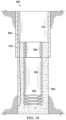
- FIG. 1is a cross-section illustrating an example liner hanger system for a wellbore penetrating a subterranean formation in accordance with the examples disclosed herein;
- FIG. 2is an enlarged cross-section illustrating a portion of the example liner hanger system of FIG. 1 in accordance with the examples disclosed herein;
- FIG. 3is a perspective illustration of a liner hanger in accordance with the examples disclosed herein;
- FIG. 4is a perspective illustration of a liner hanger in accordance with the examples disclosed herein;
- FIG. 5is a cross-section illustrating an example liner hanger in accordance with the examples disclosed herein;
- FIG. 6is a cross-section further illustrating the example liner hanger system of FIG. 5 in accordance with the examples disclosed herein;
- FIG. 7is a cross-section illustration of a liner hanger with an accelerator in accordance with the examples disclosed herein;
- FIG. 8is a cross-section illustration of a liner hanger with an accelerator in accordance with the examples disclosed herein;
- FIG. 9is a cross-section illustration of a liner hanger and an installation string with an accelerator in accordance with the examples disclosed herein;
- FIG. 10is a cross-section illustration of a liner hanger system having an accelerator actuated by a wiper plug in accordance with the examples disclosed herein;
- FIG. 11is a cross-section further illustrating the example liner hanger system of FIG. 10 in accordance with the examples disclosed herein;
- FIG. 12is a cross-section further illustrating the example liner hanger system of FIG. 11 in accordance with the examples disclosed herein;
- FIG. 13is a cross-section illustration of a liner hanger system having reactive metal sealing elements disposed on the liner in accordance with the examples disclosed herein;
- FIG. 14is a cross-section further illustrating the example liner hanger system of FIG. 13 in accordance with the examples disclosed herein;
- FIG. 15is a cross-section further illustrating the example liner hanger system of FIG. 14 in accordance with the examples disclosed herein;
- FIG. 16is a cross-section illustration of a liner hanger system having cable disposed proximate the reactive metal sealing element in accordance with the examples disclosed herein;
- FIG. 17is a cross-section further illustrating the example liner hanger system of FIG. 16 in accordance with the examples disclosed herein;
- FIG. 18is a cross-section further illustrating the example liner hanger system of FIG. 17 in accordance with the examples disclosed herein.
- the present disclosurerelates to the use of a non-expanding liner hanger, and more particularly, to the use of a non-expanding liner hanger having reactive metal sealing elements for sealing and anchoring the non-expanding liner hanger in wellbore applications.
- any use of any form of the terms “connect,” “engage,” “couple,” “attach,” or any other term describing an interaction between elementsis not meant to limit the interaction to direct interaction between the elements and may also include indirect interaction between the elements described. Further, any use of any form of the terms “connect,” “engage,” “couple,” “attach,” or any other term describing an interaction between elements includes items integrally formed together without the aid of extraneous fasteners or joining devices.
- the terms “including” and “comprising”are used in an open-ended fashion, and thus should be interpreted to mean “including, but not limited to.” Unless otherwise indicated, as used throughout this document, “or” does not require mutual exclusivity.
- uphole and downholemay be used to refer to the location of various components relative to the bottom or end of a well.
- a first component described as uphole from a second componentmay be further away from the end of the well than the second component.
- a first component described as being downhole from a second componentmay be located closer to the end of the well than the second component.
- Examples of the methods and systems described hereinrelate to the use of non-expanding liner hangers comprising reactive metal sealing elements for annular sealing and anchoring.
- sealing elementsrefers to any element used to form a seal.
- a “seal”is a barrier to the passage of a liquid and/or gas.
- the reactive metal sealing elements described hereinmay form a seal that complies with the International Organization for Standardization (ISO) 14310:2001/API Specification 11D1 1 st Edition validation standard for the Grade V5: Liquid Test.
- the reactive metalsform seals by contacting specific reaction-inducing fluids, such as a brine, where they then dissolve to produce a reaction product having a larger volume than the base reactive metal reactant.
- specific reaction-inducing fluidssuch as a brine
- the increase in metal volume of the reaction productcreates a seal at the interface of the reactive metal sealing element and any adjacent surface as the reaction product proceeds to solidify at the interface.
- Formation of the reaction productsresults in the volumetric expansion of the reactive metal sealing element.
- the solidified reaction productsalso anchor the liner hanger to the adjacent surface, securing it in the wellbore and allowing for suspension of the liner.
- the reactive metal sealing elementsmay be used in a variety of wellbore applications where an irreversible seal is desired.
- the reactive metal sealing elementsmay swell in high-salinity and/or high-temperature environments that may be unsuitable for some other species of sealing elements.
- the reactive metal sealing elementscomprise a wide variety of metals and metal alloys and may react upon contact with reaction-inducing fluids, including a variety of wellbore fluids.
- the reactive metal sealing elementsmay be used as replacements for other types of sealing elements (e.g., elastomeric sealing elements), or they may be used as backups for other types of sealing elements.
- the reactive metal sealing elementsmay be placed on an existing liner hanger without impact to or adjustment of the liner hanger outer diameter or exterior profile.
- the reactive metal sealing elementsare used on non-expanding liner hangers and are able to seal and anchor the liner hanger without expanding the liner hanger. As such, there is no need to proceed with expansion operations such as those utilizing expansion cones, etc. which may add complexity to wellbore operations and increase operation time. Moreover, in some examples, the reactive metal sealing elements do not comprise elastomeric materials and may be usable in wellbore environments where elastomeric materials may be prone to breakdown.
- the reactive metalsexpand by undergoing a reaction in the presence of a reaction-inducing fluid (e.g., a brine) to form a reaction product (e.g., metal hydroxides).
- a reaction producte.g., metal hydroxides
- the resulting reaction productsoccupy more volumetric space relative to the base reactive metal reactant. This difference in volume allows the reactive metal sealing element to form a seal at the interface of the reactive metal sealing element and any adjacent surfaces.
- Magnesiummay be used to illustrate the volumetric expansion of the reactive metal as it undergoes reaction with the reaction-inducing fluid.
- a mole of magnesiumhas a molar mass of 24 g/mol and a density of 1.74 g/cm 3 , resulting in a volume of 13.8 cm 3 /mol.
- Magnesium hydroxidethe reaction product of magnesium and an aqueous reaction-inducing fluid, has a molar mass of 60 g/mol and a density of 2.34 g/cm 3 , resulting in a volume of 25.6 cm 3 /mol.
- the magnesium hydroxide volume of 25.6 cm 3 /molis an 85% increase in volume over the 13.8 cm 3 /mol volume of the mole of magnesium.
- a mole of calciumhas a molar mass of 40 g/mol and a density of 1.54 g/cm 3 , resulting in a volume of 26.0 cm 3 /mol.
- Calcium hydroxidethe reaction product of calcium and an aqueous reaction-inducing fluid, has a molar mass of 76 g/mol and a density of 2.21 g/cm 3 , resulting in a volume of 34.4 cm 3 /mol.
- the calcium hydroxide volume of 34.4 cm 3 /molis a 32% increase in volume over the 26.0 cm 3 /mol volume of the mole of calcium.
- a mole of aluminumhas a molar mass of 27 g/mol and a density of 2.7 g/cm 3 , resulting in a volume of 10.0 cm 3 /mol.
- Aluminum hydroxidethe reaction product of aluminum and an aqueous reaction-inducing fluid, has a molar mass of 63 g/mol and a density of 2.42 g/cm 3 , resulting in a volume of 26 cm 3 /mol.
- the aluminum hydroxide volume of 26 cm 3 /molis a 160% increase in volume over the 10 cm 3 /mol volume of the mole of aluminum.
- the reactive metalmay comprise any metal or metal alloy that undergoes a reaction to form a reaction product having a greater volume than the base reactive metal or alloy reactant.
- the reactive metalsundergo a chemical transformation whereby the metals chemically react with the reaction-inducing fluid, and upon reaction form a metal hydroxide that is the principal component of the seal and anchor.
- the solidified metal hydroxideis larger in volume than the base reactive metal, allowing for sealing of the annular space around the reactive metal.
- suitable metals for the reactive metalinclude, but are not limited to, magnesium, calcium, aluminum, tin, zinc, beryllium, barium, manganese, or any combination thereof.
- Preferred metalsinclude magnesium, calcium, and aluminum.
- suitable metal alloys for the reactive metalinclude, but are not limited to, alloys of magnesium, calcium, aluminum, tin, zinc, beryllium, barium, manganese, or any combination thereof.
- Preferred metal alloysinclude alloys of magnesium-zinc, magnesium-aluminum, calcium-magnesium, or aluminum-copper.
- the metal alloysmay comprise alloyed elements that are not metallic. Examples of these non-metallic elements include, but are not limited to, graphite, carbon, silicon, boron nitride, and the like.
- the metalis alloyed to increase reactivity and/or to control the formation of oxides.
- the metal alloyis also alloyed with a dopant metal that promotes corrosion or inhibits passivation and thus increases hydroxide formation.
- dopant metalsinclude, but are not limited to, nickel, iron, copper, carbon, titanium, gallium, mercury, cobalt, iridium, gold, palladium, or any combination thereof.
- the reactive metalcomprises an oxide.
- calcium oxidereacts with water in an energetic reaction to produce calcium hydroxide.
- One mole of calcium oxideoccupies 9.5 cm 3 whereas one mole of calcium hydroxide occupies 34.4 cm 3 .
- metal oxides suitable for the reactive metalmay include, but are not limited to, oxides of any metals disclosed herein, including magnesium, calcium, aluminum, iron, nickel, copper, chromium, tin, zinc, lead, beryllium, barium, gallium, indium, bismuth, titanium, manganese, cobalt, or any combination thereof.
- the selected reactive metalis chosen such that the formed reactive metal sealing element does not dissolve or otherwise degrade in the reaction-inducing fluid.
- the use of metals or metal alloys for the reactive metal that form relatively insoluble reaction products in the reaction-inducing fluidmay be preferred.
- the magnesium hydroxide and calcium hydroxide reaction productshave very low solubility in water.
- the reactive metal sealing elementmay be positioned and configured in a way that constrains the degradation of the reactive metal sealing element in the reaction-inducing fluid due to the geometry of the area in which the reactive metal sealing element is disposed.
- the volume of the area in which the sealing element is disposedmay be less than the potential expansion volume of the volume of reactive metal disposed in said area. In some examples, this volume of area may be less than as much as 50% of the expansion volume of reactive metal. Alternatively, this volume of area may be less than 90% of the expansion volume of reactive metal. As another alternative, this volume of area may be less than 80% of the expansion volume of reactive metal. As another alternative, this volume of area may be less than 70% of the expansion volume of reactive metal.
- this volume of areamay be less than 60% of the expansion volume of reactive metal.
- a portion of the reactive metal sealing elementmay be disposed in a recess within the conduit body of the liner hanger to restrict the exposure area to only the surface portion of the reactive metal sealing element that is not disposed in the recess.
- the formed reaction products of the reactive metal reactionmay be dehydrated under sufficient pressure.
- the elevated pressuremay induce dehydration of the metal hydroxide to form the metal oxide.
- magnesium hydroxidemay be dehydrated under sufficient pressure to form magnesium oxide and water.
- calcium hydroxidemay be dehydrated under sufficient pressure to form calcium oxide and water.
- aluminum hydroxidemay be dehydrated under sufficient pressure to form aluminum oxide and water.
- the reactive metal sealing elementsmay be formed in a solid solution process, a powder metallurgy process, or through any other method as would be apparent to one of ordinary skill in the art. Regardless of the method of manufacture, the reactive metal sealing elements may be slipped over the liner hanger mandrel and held in place via any sufficient method. The reactive metal sealing elements may be placed over the mandrel in one solid piece or in multiple discrete pieces. Once in place, the reactive metal sealing element is held in position with end rings, stamped rings, retaining rings, fasteners, adhesives, set screws, swedging, or any other such method for retaining the reactive metal sealing element in position. In some alternative examples, the reactive metal sealing element may not be held in position and may slide freely on the exterior of the tubular.
- the reactive metal sealing elementsmay be formed and shaped to fit over existing liner hangers and may not require modification of the outer diameter or profile of the liner hanger in some examples.
- the liner hangermay be manufactured to comprise a recess in which the reactive metal sealing element may be disposed.
- the recessmay be of sufficient dimensions and geometry to retain the reactive metal sealing elements in the recess.
- the reactive metal sealing elementmay be cast onto the conduit body of the liner hanger.
- the diameter of the reactive metal sealing elementmay be reduced (e.g., by swaging) when disposed on the conduit body of the liner hanger.
- the reactive metal sealing elementmay include a removable barrier coating.
- the removable barrier coatingmay be used to cover the exterior surfaces of the reactive metal sealing element and prevent contact of the reactive metal with the reaction-inducing fluid.
- the removable barrier coatingmay be removed when the sealing operation is to commence.
- the removable barrier coatingmay be used to delay sealing and/or prevent premature sealing with the reactive metal sealing element.
- Examples of the removable barrier coatinginclude, but are not limited to, any species of plastic shell, organic shell, paint, dissolvable coatings (e.g., solid magnesium compounds or an aliphatic polyester), a meltable material (e.g., with a melting temperature less than 550 F), or any combination thereof.
- the removable barrier coatingmay be removed from the sealing element with any sufficient method.
- the removable barrier coatingmay be removed through dissolution, a phase change induced by changing temperature, corrosion, hydrolysis, melting, or the removable barrier coating may be time-delayed and degrade after a desired time under specific wellbore conditions.
- the reactive metal sealing elementmay include an additive which may be added to the reactive metal sealing element during manufacture as a part of the composition, or the additive may be coated onto the reactive metal sealing element after manufacturing.
- the additivemay alter one or more properties of the reactive metal sealing element.
- the additivemay improve sealing, add texturing, improve bonding, improve gripping, etc.
- the additiveinclude, but are not limited to, any species of ceramic, elastomer, glass, non-reacting metal, the like, or any combination.
- the reactive metal sealing elementmay be used to form a seal between any adjacent surfaces that are proximate to the reactive metal sealing elements.
- the reactive metal sealing elementsmay be used to form seals on casing, formation surfaces, cement sheaths or layers, and the like.
- a reactive metal sealing elementmay be used to form a seal between the outer diameter of the liner hanger and a surface of an adjacent casing.
- the reactive metal sealing elementmay be used to form a seal between the outer diameter of the liner hanger and a surface of an adjacent set cement layer.
- a reactive metal sealing elementmay be used to form a seal between the liner hanger and the outer diameter of a tie-back liner.
- a plurality of the reactive metal sealing elementsmay be used to form multiple seals between adjacent surfaces. As many reactive metal sealing elements may be provided as needed to form the desired sealing and anchoring of the liner hanger.
- the reactive metal sealing elementscomprise reactive metals and as such, they are non-elastomeric materials.
- the reactive metal sealing elementsdo not possess elasticity, and therefore, they may irreversibly expand when contacted with a reaction-inducing fluid.
- the reactive metal sealing elementsmay not return to their original size or shape even after the reaction-inducing fluid is removed from contact.
- the reaction-inducing fluidinduces a reaction in the reactive metal to form a reaction product that occupies more space than the unreacted reactive metal.
- the reaction-inducing fluidinclude, but are not limited to, saltwater (e.g., water containing one or more salts dissolved therein), brine (e.g., saturated saltwater, which may be produced from subterranean formations), seawater, or any combination thereof.
- the reaction-inducing fluidmay be from any source provided that the fluid does not contain an excess of compounds that may undesirably affect other components in the sealing element.
- the reaction-inducing fluidmay comprise a monovalent salt or a divalent salt.
- Suitable monovalent saltsmay include, for example, sodium chloride salt, sodium bromide salt, potassium chloride salt, potassium bromide salt, and the like.
- Suitable divalent saltcan include, for example, magnesium chloride salt, calcium chloride salt, calcium bromide salt, and the like.
- the salinity of the reaction-inducing fluidmay exceed 10%.
- the reactive metal sealing elements of the present disclosuremay not be impacted by contact with high-salinity fluids.
- One of ordinary skill in the art, with the benefit of this disclosure,should be readily able to select a reaction-inducing fluid for inducing a reaction with the reactive metal sealing elements.
- the reactive metal sealing elementsmay be used in high-temperature formations (e.g., in formations with zones having temperatures equal to or exceeding 350° F.).
- the use of the reactive metal sealing elements of the present disclosuremay not be impacted in high-temperature formations.
- the reactive metal sealing elementsmay be used in both high-temperature formations and with high-salinity fluids.
- a reactive metal sealing elementmay be positioned on a liner hanger and used to form a seal after contact with a brine having a salinity of 10% or greater while also being disposed in a wellbore zone having a temperature equal to or exceeding 350° F.
- FIG. 1is a cross-section of an example tubing system, generally 5 , for a wellbore 10 penetrating a subterranean formation 15 .
- the tubing system 5comprises a surface casing 20 and a surface cement sheath 25 descending from the surface 30 .
- the tubing system 5further comprises an intermediate casing 35 and intermediate cement sheath 40 deployed and nested concentrically within the surface casing 20 .
- a liner hanger 45is deployed within the intermediate casing 35 .
- the liner hanger 45may be used to suspend a liner 55 from within the intermediate casing 35 .
- the liner 55may be any conduit suitable for suspension within the wellbore 10 .
- the liner hanger 45comprises a conduit body 60 .
- the liner 55is a conduit that does not run to the surface 30 .
- the liner hanger 45seals within the intermediate casing 35 allowing the liner 55 to functionally act as an extension of the intermediate casing 35 without having to extend to the surface 30 as a separate casing string would.
- FIG. 2is an enlarged cross-section of a portion of the example tubing system 5 of FIG. 1 .
- Intermediate casing 35extends from the surface (i.e., surface 30 as illustrated in FIG. 1 ) and may be held in place with the intermediate cement sheath 40 . Although only one layer of intermediate casing 35 is illustrated, it is to be understood that as many layers of intermediate casing 35 may be used as desired. Any subsequent layers of the intermediate casing 35 may be nested concentrically within one another within the illustrated intermediate casing 35 .
- the liner hanger 45is deployed within the intermediate casing 35 .
- the liner hanger 45may be any species of non-expandable liner hanger.
- the liner hanger 45suspends a liner (i.e., liner 55 as illustrated in FIG. 1 ).
- the liner hanger 45is anchored to the intermediate casing 35 with a reactive metal sealing element 50 after the reactive metal sealing element 50 has reacted and expanded.
- the reactive metal sealing element 50is disposed on and around the conduit body 60 of the liner hanger 45 .
- the reactive metal sealing element 50forms an external seal with the adjacent interior surface of the intermediate casing 35 after the reactive metal sealing element 50 has reacted and expanded.
- the reactive metal sealing element 50expands after exposure to a reaction-inducing fluid.
- the reactive metal sealing element 50reacts to produce the expanded metal reaction product described above. As the expanded metal reaction product has a larger volume than the unreacted base reactive metal, the reactive metal sealing element 50 is able to expand and form an annular seal at the interface of the adjacent surface of the intermediate casing 35 as described above. The reactive metal sealing element 50 may continue to expand until contact with the adjacent surface is made. The formed seal prevents wellbore fluid from bypassing the liner 55 and liner hanger 45 .
- FIGS. 1 - 2are merely general applications of the principles of this disclosure in practice, and a wide variety of other examples are possible. Therefore, the scope of this disclosure is not limited in any manner to the details of any of the FIGURES described herein.
- FIG. 3is an isometric illustration of a liner hanger, generally 100 .
- the liner hanger 100couples to and forms a seal inside a casing at a coupling end 105 .
- the liner hanger 100comprises a conduit body 110 .
- Reactive metal sealing elements 115form external seals to seal against the surface of the casing and anchor the liner hanger 100 to the casing.
- a liner(not illustrated) may be coupled to and suspended from a suspending end 120 .
- Spacer elements 125may be positioned on the conduit body 110 .
- the spacer elements 125may be a polymer-based material or a metal, such as steel.
- the spacer elements 125may provide additional anchoring support to the liner hanger 100 within a fixed location or may space other conduit body 110 components such as multiple reactive metal sealing elements 115 .
- the reactive metal sealing elements 115 and the spacer elements 125alternate in a series. It is to be understood that the reactive metal sealing elements 115 may be placed in any pattern or configuration, either by itself or in conjunction with other components, such as other species of spacer elements 125 . As an example, a single reactive metal sealing element 115 may be used. As another example, multiple reactive metal sealing elements 115 may be used. As a further example, multiple reactive metal sealing elements 115 may be used in a series adjacent to one another with individual other species of spacer elements 125 placed at any point of the series. In some examples, multiple other species of spacer elements 125 may be placed at the ends of the series.
- the multiple reactive metal sealing elements 115may alternate in the series with other species of spacer elements 125 .
- the spacer elements 125may be placed on the conduit body 110 in a location that is not proximate to the reactive metal sealing elements 115 .
- the spacer elements 125may be placed on the opposing side of a retaining element or pair of retaining elements such as cup seals, end rings, stamped rings, etc. which may have a reactive metal sealing element 115 or series of reactive metal sealing elements 115 disposed on the other side or therebetween.
- FIG. 3is merely a general application of the principles of this disclosure in practice, and a wide variety of other examples are possible. Therefore, the scope of this disclosure is not limited in any manner to the details of any of the FIGURES described herein.
- FIG. 4is an isometric illustration of a liner hanger, generally 200 .
- the liner hanger 200couples to and forms a seal inside a casing at a coupling end 205 .
- the liner hanger 200comprises a conduit body 210 .
- Reactive metal sealing elements 215form external seals to seal against the surface of the casing and anchor the liner hanger 200 to the casing.
- a liner(not illustrated) may be coupled to and suspended from a suspending end 220 .
- Elastomeric sealing elements 225may be positioned on the ends of and in-between the reactive metal sealing elements 215 to prevent the applied pressure from extruding the seal formed from the reactive metal sealing elements 215 in the direction of said applied pressure, and also to supplement the sealing of the reactive metal sealing elements 215 .
- the elastomeric sealing elements 225may be replaced with other species of sealing elements such as non-reactive metal sealing elements.
- the elastomeric sealing elements 225may be replaced with retaining rings as discussed
- the reactive metal sealing elements 215 and the elastomeric sealing elements 225alternate in a series. It is to be understood that the reactive metal sealing elements 215 may be placed in any pattern or configuration, either by itself or in conjunction with other components such as other species of sealing elements (e.g., the elastomeric sealing elements 225 or non-reactive metal sealing elements) or retaining elements. As an example, a single reactive metal sealing element 215 may be used. As another example, multiple reactive metal sealing elements 215 may be used. As a further example, multiple reactive metal sealing elements 215 may be used in a series adjacent to one another with individual other species of sealing elements or retaining elements placed at the ends of the series.
- multiple other species of sealing elements or retaining elementsmay be placed at the ends of the series.
- the multiple reactive metal sealing elements 215may alternate in the series with the other species of sealing elements or retaining elements.
- the other species of sealing or retaining elementsmay be placed on the conduit body 110 in a location that is not proximate to the reactive metal sealing elements 215 .
- the other species of elastomeric sealing elements 225may be placed on the opposing side of a retaining element or pair of retaining elements such as cup seals, end rings, stamped rings, etc. which may have a reactive metal sealing element 215 or series of reactive metal sealing elements 215 disposed on the other side or therebetween.
- the elastomeric sealing elements 225may be any species of polymer.
- the elastomeric sealing elements 225are a swellable elastomer and may comprise any oil-swellable, water-swellable, and/or combination of swellable non-metal material as would occur to one of ordinary skill in the art.
- the swellable elastomeric sealing elements 225may swell when exposed to a swell-inducing fluid (e.g., an oleaginous or aqueous fluid).
- the elastomeric sealing elements 225may swell through diffusion whereby the swell-inducing fluid is absorbed into the structure of the elastomeric sealing elements 225 where a portion of the swell-inducing fluid may be retained.
- the swell-inducing fluidmay continue to diffuse into elastomeric sealing elements 225 , causing the elastomeric sealing elements 225 to swell until they contact an adjacent surface.
- the elastomeric sealing elements 225may work in tandem with the reactive metal sealing elements 215 to create a differential annular seal around the liner hanger 200 .
- FIG. 4is merely a general application of the principles of this disclosure in practice, and a wide variety of other examples are possible. Therefore, the scope of this disclosure is not limited in any manner to the details of any of the FIGURES described herein.
- FIG. 5is a cross-section illustration of an example liner hanger 300 .
- Liner hanger 300comprises a reactive metal sealing element 310 disposed on a conduit body 315 .
- the reactive metal sealing element 310may be held in place on the conduit body 315 with end rings 320 .
- End rings 320are optional and may be substituted for other elements sufficient to maintain the reactive metal sealing element 310 in position when the liner hanger 300 is introduced downhole.
- the reactive metal sealing element 310may be held in place with set screws or may be disposed in a recess precluding the need for any species of retaining ring or other retaining element.
- no retaining meansmay be provided and the reactive metal sealing element 310 may move freely on the conduit body 315 .
- the reactive metal sealing element 310may seal against surface 325 , illustrated as a surface of an intermediate casing, but may also be the surface of a set cement layer. Surface 325 is proximate to the reactive metal sealing element 310 .
- Retaining elements 330are located downstream of the reactive metal sealing element 310 . In the illustrated example, the retaining elements 330 are positioned on both sides of the reactive metal sealing element 310 . Retaining elements 330 may be positioned on both sides of the reactive metal sealing element 310 when bi-directional flow is anticipated. As such, there is a retaining element 30 downstream of the reactive metal sealing element 310 when flow occurs in either the uphole or downhole direction.
- Restraints 335may be positioned on or around retaining element 330 to restrain retaining element 330 while the liner hanger 300 is run in hole. Restraints 335 may be a band, clamp, strip, etc. comprising a degradable material.
- the degradable materialmay include, but is not limited to, a dissolvable salt, a dissolvable metal, a meltable material, a degradable polymer, and any combination of materials.
- the restraints 335may also take other forms, including threaded or bolted connections, so long as the removal of the connections does not impact the ability of the retaining element 330 to retain the reaction products produced from the reactive metal sealing element 310 reaction.
- the restraints 335may degrade over time in the wellbore environment or may be actively degraded chemically with a wellbore fluid, acid, or a solvent.
- the restraints 335may comprise a different reactive metal than the reactive metal sealing element 310 , and specifically may comprise a reactive metal that reacts at a faster rate than the reactive metal of the reactive metal sealing element 310 .
- the restraints 335may be configured to comprise a degradable material that is removed faster than the reaction rate of the reactive metal sealing element 310 . As such, the restraints 335 are removed at a sufficiently fast rate to allow the retaining elements 330 to actuate in position to prevent the washout of the reaction products.
- FIG. 6is a cross-section illustration of the example liner hanger 300 of FIG. 5 after actuation of the retaining elements 330 .
- the retaining elements 330may be actuated to expand outward.
- the retaining elements 330comprise cup seals, but may comprise other species of retaining elements 330 in other examples.
- Retaining elements 330may be biased to spring out on its own, it may be spring energized, or it may be flow energized. In spring energized examples, the retaining elements 330 may be actuated by the spring force of an internal spring released upon removal of restraint 335 .
- the retaining elements 330may be energized through fluid flow into the retaining elements 330 to force them open. Once actuated, the retaining elements 330 may prevent the washout of the reaction products formed from the reaction of the reactive metal sealing element 310 and a reaction-inducing fluid. Washout may be prevented by the retaining elements 330 forming a seal to trap and retain the reaction products such that they do not flow downstream past the retaining elements 330 .
- the retaining elements 330may be porous and may allow fluid flow therethrough while still retaining the reaction products. In some other optional examples, the retaining elements 330 may not be porous. The reaction products may then aggregate and to seal against the adjacent surface 325 . The retaining elements 330 may be degraded if desired. In other examples, the retaining elements 330 may be permanent.
- the reactive metal sealing elements 310are illustrated as disposed between a pair of retaining elements 330 . It is to be understood that the reactive metal sealing elements 310 may be placed in any pattern or configuration with the retaining elements 330 . As an example, multiple reactive metal sealing elements 310 may alternate in the series with the retaining elements 330 . In some additional examples, the retaining elements 330 may be placed on the conduit body 315 in a location that is not proximate to the reactive metal sealing elements 310 . For example, the retaining elements 330 may be placed on the opposing side of another species of retaining element or pair of retaining elements such as end rings, stamped rings, etc.
- a retaining element 330such as a cup seal, may be disposed within a series of reactive metal sealing elements 310 disposed on the conduit body 315 of the liner hanger 300 .
- FIGS. 5 and 6are merely a general application of the principles of this disclosure in practice, and a wide variety of other examples are possible. Therefore, the scope of this disclosure is not limited in any manner to the details of any of the FIGURES described herein.
- FIG. 7is a cross-section illustration of an example liner hanger 400 .
- Liner hanger 400comprises two reactive metal sealing elements 405 disposed on a conduit body 410 .
- the reactive metal sealing elements 405may be held in place, before and/or after reaction, on the conduit body 410 by retaining elements such as the end rings or cup seals as discussed above.
- the reactive metal sealing elements 405may seal against surface 415 , illustrated as a surface of an intermediate casing, but may also be the surface of a set cement layer. Surface 415 is proximate to the reactive metal sealing elements 405 .
- Accelerator 420is located between the reactive metal sealing elements 405 . In the illustrated example of FIG.
- the accelerator 420is a heating element which provides heat to the reactive metal sealing elements 405 to accelerate the sealing and anchoring process.
- the heating element of the accelerator 420may be chemical activated or electrically activated.
- wellbore fluidsmay react with materials within the heating element to produce an exothermic reaction which generates sufficient heat to accelerate the sealing and anchoring process of the reactive metal sealing elements 405 .
- the heating elementmay be a heater powered by a power source such as a battery or electrical cable.
- the accelerator 420may be remotely activated, time delayed, or wirelessly activated as desired.
- the reactive metal sealing elements 405are illustrated as disposed on either side of the accelerator 420 . It is to be understood that the reactive metal sealing elements 405 may be placed in any pattern or configuration with the accelerator 420 as well as any additional elements which may be present such as retaining elements, spacer elements, etc. As an example, multiple reactive metal sealing elements 405 may alternate in the series with an accelerator 420 or accelerators 420 .
- FIG. 7is merely a general application of the principles of this disclosure in practice, and a wide variety of other examples are possible. Therefore, the scope of this disclosure is not limited in any manner to the details of any of the FIGURES described herein.
- FIG. 8is a cross-section illustration of an example liner hanger 500 .
- Liner hanger 500comprises a reactive metal sealing element 505 disposed on a conduit body 510 .
- the reactive metal sealing element 505may be held in place, before and/or after reaction, on the conduit body 510 by retaining elements such as the end rings or cup seals discussed above.
- the reactive metal sealing element 505may seal against surface 515 , illustrated as a surface of an intermediate casing, but may also be the surface of a set cement layer. Surface 515 is proximate to the reactive metal sealing element 505 .
- Accelerator 520is proximate to the reactive metal sealing element 505 . In the illustrated example of FIG.
- the accelerator 520is a voltage element which provides an electrical current to the reactive metal sealing element 505 to accelerate the sealing and anchoring process.
- the voltage element of the accelerator 520may be electrically activated by a power source such as a battery or electrical cable.
- the accelerator 520may be remotely activated, time delayed, or wirelessly activated as desired.
- the reactive metal sealing element 505is illustrated as disposed on one side of the accelerator 520 . It is to be understood that the reactive metal sealing element 505 may be placed in any pattern or configuration with the accelerator 520 as well as any additional elements which may be present such as retaining elements, spacer elements, etc. As an example, multiple reactive metal sealing elements 505 may alternate in the series with an accelerator 420 or accelerators 420 .
- FIG. 8is merely a general application of the principles of this disclosure in practice, and a wide variety of other examples are possible. Therefore, the scope of this disclosure is not limited in any manner to the details of any of the FIGURES described herein.
- FIG. 9is a cross-section illustration of an example wellbore system, generally 600 , which comprises liner hanger 605 .
- Liner hanger 605comprises a reactive metal sealing element 610 .
- the reactive metal sealing element 610seals against surface 615 , illustrated as a surface of an intermediate casing, but may also be the surface of a set cement layer. Surface 615 is proximate to the reactive metal sealing element 610 .
- Accelerator 620has been deployed on the installation string 625 .
- the accelerator 620is positioned proximate to the reactive metal sealing element 610 to accelerate the sealing and anchoring process of the reactive metal sealing element 610 .
- the accelerator 620may be a heating or voltage element as described above and may be remotely activated, time delayed, or wirelessly activated as desired.
- Liner hanger 605has a liner 630 suspended downhole.
- the installation string 625is coupled to and installs the liner hanger 605 , which has the liner 630 suspended therefrom.
- the sealing and anchoring process of the reactive metal sealing element 610proceeds to seal and anchor the liner hanger 605 to the surface 615 .
- the installation string 625is tugged by pulling on it from the surface 615 . Tugging the installation string 625 may test whether the liner hanger 605 is successfully anchored to the surface 615 . If the liner hanger 605 is verified as being successfully installed, the liner hanger 605 is decoupled from the installation string 625 .
- the installation string 625as well as the accelerator 620 disposed thereon, are then pulled uphole and removed from the wellbore.
- FIG. 9is merely a general application of the principles of this disclosure in practice, and a wide variety of other examples are possible. Therefore, the scope of this disclosure is not limited in any manner to the details of any of the FIGURES described herein.
- FIG. 10is a cross-section illustration of an example wellbore system, generally 700 , which comprises liner hanger 705 .
- Liner hanger 705comprises a reactive metal sealing element 710 .
- the reactive metal sealing element 710seals against surface 715 , illustrated as a surface of an intermediate casing, but may also be the surface of a set cement layer. Surface 715 is proximate to the reactive metal sealing element 710 .
- Accelerator 720has been deployed on the installation string 725 .
- the accelerator 720is positioned proximate the reactive metal sealing element 710 to accelerate the sealing and anchoring process of the reactive metal sealing element 710 .
- the accelerator 720may be a heating or voltage element as described above.
- Liner hanger 705has a liner 730 suspended downhole.
- the installation string 725is coupled to and installs the liner hanger 705 , which has the liner 730 suspended therefrom.
- the activation of the accelerator 720occurs when the wiper plug 735 or the preceding cement slurry 740 passes the accelerator 720 .
- the wiper plug 735 or preceding cement slurry 740may trigger activation of the accelerator 720 by actuating a switch on the accelerator 720 , chemical activation of a component within the accelerator 720 , triggering a sensor within the accelerator 720 , etc.
- the wiper plugmay be substituted for any species of a wide variety of tools that are similarly conveyed along the interior of the tubing string including darts, cementing plugs, balls, and wireline tools.
- FIG. 11is a cross-section illustrating the example wellbore system of 700 after the passage of the wiper plug 735 and the preceding cement slurry 740 .
- the sealing and anchoring process of the reactive metal sealing element 710has proceeded to seal and anchor the liner hanger 705 to the surface 715 .
- the cement slurry 740has also been positioned and may be in the process of setting and then sealing and anchoring the liner 730 in place.
- the installation string 725is tugged by pulling on it from the surface. Tugging the installation string 725 may test whether the liner hanger 705 is successfully anchored to the surface 715 .
- FIG. 12is a cross-section illustrating the example wellbore system of 700 of FIG. 11 where the liner hanger 705 has been verified as being successfully installed and was decoupled from the installation string 725 .
- FIGS. 10 - 12is merely a general application of the principles of this disclosure in practice, and a wide variety of other examples are possible. Therefore, the scope of this disclosure is not limited in any manner to the details of any of the FIGURES described herein.
- FIG. 13is a cross-section illustration of an example wellbore system, generally 800 , which comprises liner hanger 805 .
- Liner hanger 805comprises a reactive metal sealing element 810 .
- the reactive metal sealing element 810seals against surface 815 , illustrated as a surface of an intermediate casing, but may also be the surface of a set cement layer. Surface 815 is proximate to the reactive metal sealing element 810 .
- Accelerator 820has been deployed on an installation string 825 .
- the accelerator 820is positioned proximate the reactive metal sealing element 810 to accelerate the sealing and anchoring process of the reactive metal sealing element 810 .
- the accelerator 820may be a heating or voltage element as described above.
- Liner hanger 805has a liner 830 suspended downhole.
- the installation string 825is coupled to and installs the liner hanger 805 , which has the liner 830 suspended therefrom.
- the activation of the accelerator 820may be remotely activated, time delayed, or wirelessly activated as desired. It is also to be understood, that use of an accelerator 820 is optional in the example of FIG. 13 and is presented here to describe one potential method of the installation of the liner hanger 805 .
- Liner 830comprises liner reactive metal sealing elements 835 and production screens 840 . Liner reactive metal sealing elements 835 may be accelerated in some alternative examples via the accelerator 820 or an alternative accelerator positioned on the liner 830 . In the illustrated example of FIG. 13 , the liner reactive metal sealing elements 835 are not accelerated.
- FIG. 14is a cross-section illustrating the example wellbore system of 800 of FIG. 13 after the sealing and anchoring process of the reactive metal sealing element 810 has proceeded to seal and anchor the liner hanger 805 to the surface 815 .
- the installation string 825is tugged by pulling on it from the surface 815 . Tugging the installation string 825 may test whether the liner hanger 805 is successfully anchored to the surface 815 .
- the liner reactive metal sealing elements 835were not accelerated, they may not have completed the sealing and anchoring process as quickly as the reactive metal sealing elements 810 .
- different species of reactive metalsmay be chosen for the reactive metal sealing elements 810 and the liner reactive metal sealing elements 835 such that the rate of the sealing process may be tailored as desired.
- FIG. 15is a cross-section illustrating the example wellbore system of 800 of FIG. 14 where the liner reactive metal sealing elements 835 have completed the sealing and anchoring process for the liner 830 .
- Productionmay occur through production screen 840 .
- FIG. 15illustrates production occurring through the liner 830 and the sealing and anchoring of the liner 830 with reactive metal sealing elements 835 instead of a cement.
- FIGS. 13 - 15is merely a general application of the principles of this disclosure in practice, and a wide variety of other examples are possible. Therefore, the scope of this disclosure is not limited in any manner to the details of any of the FIGURES described herein.
- FIG. 16is a cross-section illustration of an example wellbore system, generally 900 , which comprises liner hanger 905 .
- Liner hanger 905comprises a reactive metal sealing element 910 .
- the reactive metal sealing element 910seals against surface 915 , illustrated as a surface of an intermediate casing, but may also be the surface of a set cement layer. Surface 915 is proximate to the reactive metal sealing element 910 .
- Accelerator 920has been deployed on an installation string 925 .
- the accelerator 920is positioned proximate to the reactive metal sealing element 910 to accelerate the sealing and anchoring process of the reactive metal sealing element 910 .
- the accelerator 920may be a heating or voltage element as described above.
- Liner hanger 905has a liner 930 suspended downhole.
- the installation string 925is coupled to and installs the liner hanger 905 , which has the liner 930 suspended therefrom.
- the activation of the accelerator 920occurs when the wiper plug 935 or the preceding cement slurry 940 passes the accelerator 920 .
- the wiper plug 935 or preceding cement slurry 940may trigger activation of the accelerator 920 by actuating a switch on the accelerator 920 , chemical activation of a component within the accelerator 920 , triggering a sensor within the accelerator 920 , etc.
- Cable 950is disposed in the annular region between the surface 915 and the liner hanger 905 .
- Cable 950may be an electrical cable, fiber optic cable, control line, hydraulic dine, gas lift, or a combination of cables.
- FIG. 17is a cross-section illustrating the example wellbore system of 900 after the passage of the wiper plug 935 and the preceding cement slurry 940 .
- the sealing and anchoring process of the reactive metal sealing element 910has proceeded to seal and anchor the liner hanger 905 to the surface 915 .
- the cement slurry 940has also been positioned and may be in the process of setting and then sealing and anchoring the liner 930 in place.
- the installation string 925is tugged by pulling on it from the surface 915 . Tugging the installation string 925 may test whether the liner hanger 905 is successfully anchored to the surface 915 .
- the reactive metal sealing element 910has also sealed around cable 950 allowing cable 950 to bypass the seal and anchor formed by the solidified reactive metal sealing element 910 .
- cable 950may convey electricity, pressure, data, etc. across the formed seal as desired without the need to conduct a separate bypass or installation operation and also without impact to the integrity of the seal and anchor.
- FIG. 18is a cross-section illustrating the example wellbore system of 900 of FIG. 17 where the liner hanger 905 has been verified as being successfully installed and was decoupled from the installation string 925 .
- the installation string 925as well as the accelerator 920 disposed thereon, are pulled uphole and removed from the wellbore as illustrated by their absence from the illustration of FIG. 18 .
- Cable 950remains in place after removal of the installation string 925 .
- FIGS. 16 - 18is merely a general application of the principles of this disclosure in practice, and a wide variety of other examples are possible. Therefore, the scope of this disclosure is not limited in any manner to the details of any of the FIGURES described herein.
- non-expandable liner hangers and the reactive metal sealing elementsmay also directly or indirectly affect the various downhole equipment and tools that may come into contact with the non-expandable liner hangers and the reactive metal sealing elements during operation.
- Such equipment and toolsmay include, but are not limited to: wellbore casing, wellbore liner, completion string, insert strings, drill string, coiled tubing, slickline, wireline, drill pipe, drill collars, mud motors, downhole motors and/or pumps, surface-mounted motors and/or pumps, centralizers, turbolizers, scratchers, floats (e.g., shoes, collars, valves, etc.), logging tools and related telemetry equipment, actuators (e.g., electromechanical devices, hydromechanical devices, etc.), sliding sleeves, production sleeves, plugs, screens, filters, flow control devices (e.g., inflow control devices, autonomous inflow control devices, outflow control devices, etc.), couplings (e.g., electro-hydraulic wet connect, dry connect, inductive coupler, etc.), control lines (e.g., electrical, fiber optic, hydraulic, etc.), surveillance lines, drill bits and reamers, sensors or distributed sensors, downhole heat exchangers, valves and corresponding
- An example methodcomprises positioning a non-expandable liner hanger in a wellbore, wherein a liner is coupled to the liner hanger, wherein the liner hanger comprises: a conduit body; and a reactive metal sealing element disposed on the conduit body, wherein the reactive metal sealing element comprises a reactive metal having a first volume.
- the methodfurther comprises contacting the reactive metal with a fluid that reacts with the reactive metal to produce a reaction product having a second volume greater than the first volume; and contacting a surface adjacent to the reactive metal sealing element with the reaction product to form a seal against the surface and to anchor the liner hanger from the surface, wherein anchoring the liner hanger to the surface suspends the liner in the wellbore.
- the methodmay include one or more of the following features individually or in combination.
- the reactive metalmay comprise a metal selected from the group consisting of magnesium, calcium, aluminum, tin, zinc, beryllium, barium, manganese, and any combination thereof.
- the reactive metalmay comprise a metal alloy selected from the group consisting of magnesium-zinc, magnesium-aluminum, calcium-magnesium, aluminum-copper, and any combination thereof.
- the liner hangermay comprise a spacer element.
- the methodmay further comprise placing a cup seal proximate to the reactive metal sealing element.
- the methodmay further comprise accelerating the reaction of the reactive metal with the fluid using an accelerator.
- the acceleratormay be a heating element.
- the acceleratormay be a voltage element.
- the acceleratormay be actuated with a wiper plug, darts, cementing plugs, balls, or wireline tool conveyed through the interior of the conduit body.
- the liner hangermay comprise the accelerator.
- the acceleratormay be coupled to an installation string used to position the liner hanger in the wellbore. A cable may traverse the seal.
- non-expandable liner hangersfor suspending a liner in accordance with the disclosure and the illustrated FIGURES.
- An example non-expandable liner hangercomprises a conduit body; and a reactive metal sealing element disposed on the conduit body.
- the non-expandable liner hangermay include one or more of the following features individually or in combination.
- the reactive metalmay comprise a metal selected from the group consisting of magnesium, calcium, aluminum, tin, zinc, beryllium, barium, manganese, and any combination thereof.
- the reactive metalmay comprise a metal alloy selected from the group consisting of magnesium-zinc, magnesium-aluminum, calcium-magnesium, aluminum-copper, and any combination thereof.
- the liner hangermay comprise a spacer element.
- the liner hangermay further comprise placing a cup seal proximate to the reactive metal sealing element.
- the reaction of the reactive metal with the fluidmay be accelerated using an accelerator.
- the acceleratormay be a heating element.
- the acceleratormay be a voltage element.
- the acceleratormay be actuated with a wiper plug, darts, cementing plugs, balls, or wireline tool conveyed through the interior of the conduit body.
- the liner hangermay comprise the accelerator.
- the acceleratormay be coupled to an installation string used to position the liner hanger in the wellbore. A cable may traverse the seal.
- An example systemcomprises a non-expandable liner hanger comprising: a conduit body; and a reactive metal sealing element disposed on the conduit body.
- the systemfurther comprises the liner suspended from the liner hanger; and an installation string coupled to the liner hanger.
- the systemmay include one or more of the following features individually or in combination.
- the reactive metalmay comprise a metal selected from the group consisting of magnesium, calcium, aluminum, tin, zinc, beryllium, barium, manganese, and any combination thereof.
- the reactive metalmay comprise a metal alloy selected from the group consisting of magnesium-zinc, magnesium-aluminum, calcium-magnesium, aluminum-copper, and any combination thereof.
- the liner hangermay comprise a spacer element.
- the liner hangermay further comprise placing a cup seal proximate to the reactive metal sealing element.
- the reaction of the reactive metal with the fluidmay be accelerated using an accelerator.
- the acceleratormay be a heating element.
- the acceleratormay be a voltage element.
- the acceleratormay be actuated with a wiper plug, darts, cementing plugs, balls, or wireline tool conveyed through the interior of the conduit body.
- the acceleratormay be disposed on the liner hanger or the installation string.
- the acceleratormay be coupled to an installation string used to position the liner hanger in the wellbore.
- a cablemay traverse the seal.
- ranges from any lower limitmay be combined with any upper limit to recite a range not explicitly recited, as well as ranges from any lower limit may be combined with any other lower limit to recite a range not explicitly recited.
- ranges from any upper limitmay be combined with any other upper limit to recite a range not explicitly recited.
- any numerical range with a lower limit and an upper limitis disclosed, any number and any included range falling within the range are specifically disclosed.
- every range of values(of the form, “from about a to about b,” or, equivalently, “from approximately a to b,” or, equivalently, “from approximately a-b”) disclosed herein is to be understood to set forth every number and range encompassed within the broader range of values even if not explicitly recited.
- every point or individual valuemay serve as its own lower or upper limit combined with any other point or individual value or any other lower or upper limit, to recite a range not explicitly recited.
Landscapes
- Engineering & Computer Science (AREA)
- Geology (AREA)
- Life Sciences & Earth Sciences (AREA)
- Mining & Mineral Resources (AREA)
- Geochemistry & Mineralogy (AREA)
- Fluid Mechanics (AREA)
- Environmental & Geological Engineering (AREA)
- General Life Sciences & Earth Sciences (AREA)
- Physics & Mathematics (AREA)
- General Engineering & Computer Science (AREA)
- Mechanical Engineering (AREA)
- Gasket Seals (AREA)
- Branch Pipes, Bends, And The Like (AREA)
- Protection Of Pipes Against Damage, Friction, And Corrosion (AREA)
- Prevention Of Electric Corrosion (AREA)
- Particle Accelerators (AREA)
- Media Introduction/Drainage Providing Device (AREA)
- Holders For Apparel And Elements Relating To Apparel (AREA)
Abstract
Description
Claims (20)
Priority Applications (10)
| Application Number | Priority Date | Filing Date | Title |
|---|---|---|---|
| US17/124,217US11572749B2 (en) | 2020-12-16 | 2020-12-16 | Non-expanding liner hanger |
| CN202080107074.9ACN116391071B (en) | 2020-12-16 | 2020-12-18 | Non-expandable liner hanger |
| PCT/US2020/066193WO2022132179A1 (en) | 2020-12-16 | 2020-12-18 | Non-expanding liner hanger |
| CA3200511ACA3200511A1 (en) | 2020-12-16 | 2020-12-18 | Non-expanding liner hanger |
| GB2306720.0AGB2615053B (en) | 2020-12-16 | 2020-12-18 | Non-expanding liner hanger |
| AU2020481934AAU2020481934A1 (en) | 2020-12-16 | 2020-12-18 | Non-expanding liner hanger |
| MX2023005687AMX2023005687A (en) | 2020-12-16 | 2020-12-18 | Non-expanding liner hanger. |
| NL2029758ANL2029758B1 (en) | 2020-12-16 | 2021-11-15 | Non-expanding liner hanger |
| NO20230533ANO20230533A1 (en) | 2020-12-16 | 2023-05-05 | |
| CONC2023/0006489ACO2023006489A2 (en) | 2020-12-16 | 2023-05-16 | Non-Expanding Short Casing Hanger |
Applications Claiming Priority (1)
| Application Number | Priority Date | Filing Date | Title |
|---|---|---|---|
| US17/124,217US11572749B2 (en) | 2020-12-16 | 2020-12-16 | Non-expanding liner hanger |
Publications (2)
| Publication Number | Publication Date |
|---|---|
| US20220186575A1 US20220186575A1 (en) | 2022-06-16 |
| US11572749B2true US11572749B2 (en) | 2023-02-07 |
Family
ID=81941299
Family Applications (1)
| Application Number | Title | Priority Date | Filing Date |
|---|---|---|---|
| US17/124,217ActiveUS11572749B2 (en) | 2020-12-16 | 2020-12-16 | Non-expanding liner hanger |
Country Status (10)
| Country | Link |
|---|---|
| US (1) | US11572749B2 (en) |
| CN (1) | CN116391071B (en) |
| AU (1) | AU2020481934A1 (en) |
| CA (1) | CA3200511A1 (en) |
| CO (1) | CO2023006489A2 (en) |
| GB (1) | GB2615053B (en) |
| MX (1) | MX2023005687A (en) |
| NL (1) | NL2029758B1 (en) |
| NO (1) | NO20230533A1 (en) |
| WO (1) | WO2022132179A1 (en) |
Families Citing this family (15)
| Publication number | Priority date | Publication date | Assignee | Title |
|---|---|---|---|---|
| GB2605062B (en) | 2020-01-17 | 2024-09-25 | Halliburton Energy Services Inc | Voltage to accelerate/decelerate expandable metal |
| GB2604814B (en) | 2020-01-17 | 2024-10-09 | Halliburton Energy Services Inc | Heaters to accelerate setting of expandable metal |
| NO20230030A1 (en) | 2020-08-13 | 2023-01-12 | Halliburton Energy Services Inc | Expandable metal displacement plug |
| MX2023009992A (en) | 2021-04-12 | 2023-09-06 | Halliburton Energy Services Inc | Expandable metal as backup for elastomeric elements. |
| US12326060B2 (en) | 2021-05-21 | 2025-06-10 | Halliburton Energy Services, Inc. | Wellbore anchor including one or more activation chambers |
| NO20231087A1 (en) | 2021-05-28 | 2023-10-13 | Halliburton Energy Services Inc | Individual separate chunks of expandable metal |
| PL446571A1 (en) | 2021-05-28 | 2024-05-20 | Halliburton Energy Services, Inc. | Quick-setting, expandable metal |
| US12421824B2 (en) | 2021-05-29 | 2025-09-23 | Halliburton Energy Services, Inc. | Using expandable metal as an alternate to existing metal to metal seals |
| BR112023021016A2 (en)* | 2021-05-29 | 2023-12-19 | Halliburton Energy Services Inc | SELF-ACTIVATION SEAL ASSEMBLY SUPPORT |
| WO2022255988A1 (en) | 2021-06-01 | 2022-12-08 | Halliburton Energy Services, Inc. | Expanding metal used in forming support structures |
| US12378832B2 (en) | 2021-10-05 | 2025-08-05 | Halliburton Energy Services, Inc. | Expandable metal sealing/anchoring tool |
| US11668158B1 (en)* | 2021-11-30 | 2023-06-06 | Saudi Arabian Oil Company | Tieback casing to workover liner using a crossover |
| US12305459B2 (en) | 2022-06-15 | 2025-05-20 | Halliburton Energy Services, Inc. | Sealing/anchoring tool employing an expandable metal circlet |
| US12385340B2 (en) | 2022-12-05 | 2025-08-12 | Halliburton Energy Services, Inc. | Reduced backlash sealing/anchoring assembly |
| US20250109656A1 (en)* | 2023-09-28 | 2025-04-03 | Halliburton Energy Services, Inc. | Multilateral lateral bore completion employing an expandable metal anchor |
Citations (179)
| Publication number | Priority date | Publication date | Assignee | Title |
|---|---|---|---|---|
| US1982569A (en) | 1933-04-05 | 1934-11-27 | Arther J Byrd | Protective device for poles |
| US3046601A (en) | 1959-08-28 | 1962-07-31 | Shell Oil Co | Cavity configuration determination |
| US3385367A (en) | 1966-12-07 | 1968-05-28 | Kollsman Paul | Sealing device for perforated well casing |
| US4445694A (en) | 1982-12-17 | 1984-05-01 | Westinghouse Electric Corp. | All-metal expandable ultra high vacuum seal |
| US4612985A (en) | 1985-07-24 | 1986-09-23 | Baker Oil Tools, Inc. | Seal assembly for well tools |
| US4846278A (en) | 1986-05-21 | 1989-07-11 | Du Pont (Australia) Ltd. | Borehole plug and method |
| US5139235A (en) | 1991-07-26 | 1992-08-18 | Kilmer Willis G | Corner fence post system |
| US5163321A (en) | 1989-10-17 | 1992-11-17 | Baroid Technology, Inc. | Borehole pressure and temperature measurement system |
| US5803177A (en) | 1996-12-11 | 1998-09-08 | Halliburton Energy Services | Well treatment fluid placement tool and methods |
| US6098717A (en) | 1997-10-08 | 2000-08-08 | Formlock, Inc. | Method and apparatus for hanging tubulars in wells |
| US6321861B1 (en) | 1999-06-15 | 2001-11-27 | Henry S. Leichter | Auger |
| US6367845B1 (en) | 1999-11-09 | 2002-04-09 | Grant Prideco, L.P. | Control line coupling and tubular string-control line assembly employing same |
| US20020125008A1 (en) | 2000-08-03 | 2002-09-12 | Wetzel Rodney J. | Intelligent well system and method |
| GB2381278A (en) | 2001-10-26 | 2003-04-30 | Kevin Malcolm Davey | A post base |
| US6581682B1 (en) | 1999-09-30 | 2003-06-24 | Solinst Canada Limited | Expandable borehole packer |
| US20030150614A1 (en) | 1999-04-30 | 2003-08-14 | Brown Donald W. | Canister, sealing method and composition for sealing a borehole |
| US20030159829A1 (en) | 2002-02-27 | 2003-08-28 | Fripp Michael L. | Downhole tool actuator |
| US6640893B1 (en) | 1999-03-29 | 2003-11-04 | Groupement Europeen d'Interet Economique “Exploitation” Miniere de la Chaleur (G.E.I.E. EMC) | Wellbore packer |
| US20040118572A1 (en) | 2002-12-23 | 2004-06-24 | Ken Whanger | Expandable sealing apparatus |
| US20040149418A1 (en) | 2001-06-05 | 2004-08-05 | Bosma Martin Gerard Rene | In-situ casting of well equipment |
| US20040244994A1 (en) | 2001-09-10 | 2004-12-09 | Weatherford/Lamb, Inc. | Expandable hanger and packer |
| US20050092485A1 (en) | 2002-09-23 | 2005-05-05 | Brezinski Michael M. | Annular isolators for expandable tubulars in wellbores |
| US20050171248A1 (en) | 2004-02-02 | 2005-08-04 | Yanmei Li | Hydrogel for use in downhole seal applications |
| US20050199401A1 (en) | 2004-03-12 | 2005-09-15 | Schlumberger Technology Corporation | System and Method to Seal Using a Swellable Material |
| US20050257961A1 (en) | 2004-05-18 | 2005-11-24 | Adrian Snell | Equipment Housing for Downhole Measurements |
| GB2416796A (en) | 2003-10-03 | 2006-02-08 | Schlumberger Holdings | Well packer having an energized sealing element and associated method |
| US7007910B1 (en) | 1998-08-11 | 2006-03-07 | Klaus Krinner | Device for fastening poles, posts, masts or the like in the ground, and method for manufacturing a fastening device |
| US7040404B2 (en) | 2001-12-04 | 2006-05-09 | Halliburton Energy Services, Inc. | Methods and compositions for sealing an expandable tubular in a wellbore |
| US20060175065A1 (en) | 2004-12-21 | 2006-08-10 | Schlumberger Technology Corporation | Water shut off method and apparatus |
| US20070089911A1 (en) | 2005-05-10 | 2007-04-26 | Moyes Peter B | Downhole tool |
| US20070095532A1 (en) | 2003-06-30 | 2007-05-03 | Philip Head | Apparatus and method for sealing a wellbore |
| US20070125532A1 (en) | 2005-12-01 | 2007-06-07 | Murray Douglas J | Self energized backup system for packer sealing elements |
| US20070200299A1 (en) | 2006-02-17 | 2007-08-30 | Innicor Subsurface Technologies Inc | Spring/seal element |
| US20070257405A1 (en) | 2004-05-25 | 2007-11-08 | Easy Well Solutions As | Method and a Device for Expanding a Body Under Overpressure |
| US20080066931A1 (en) | 2006-09-18 | 2008-03-20 | Baker Hughes Incorporated | Gas activated actuator device for downhole tools |
| US7387158B2 (en) | 2006-01-18 | 2008-06-17 | Baker Hughes Incorporated | Self energized packer |
| US20080142214A1 (en) | 2006-12-13 | 2008-06-19 | Carl Keller | Pore fluid sampling system with diffusion barrier |
| US20080149351A1 (en) | 2006-12-20 | 2008-06-26 | Schlumberger Technology Corporation | Temporary containments for swellable and inflatable packer elements |
| US20080185158A1 (en) | 2007-02-06 | 2008-08-07 | Halliburton Energy Services, Inc. | Swellable packer with enhanced sealing capability |
| US20080185150A1 (en)* | 2007-02-05 | 2008-08-07 | Irvine Cardno Brown | Apparatus and Method for Cleaning a Well |
| US20080220991A1 (en) | 2007-03-06 | 2008-09-11 | Halliburton Energy Services, Inc. - Dallas | Contacting surfaces using swellable elements |
| US7431082B2 (en) | 2005-08-19 | 2008-10-07 | Baker Hughes Incorporated | Retaining lines in bypass groove on downhole equipment |
| US20090020286A1 (en) | 2007-07-17 | 2009-01-22 | Johnson Rick D | Plugging a Mined-Through Well |
| US20090120640A1 (en) | 2007-11-09 | 2009-05-14 | David Kulakofsky | Methods of Integrating Analysis, Auto-Sealing, and Swellable-Packer Elements for a Reliable Annular Seal |
| US20090130938A1 (en) | 2007-05-31 | 2009-05-21 | Baker Hughes Incorporated | Swellable material and method |
| US7543639B2 (en) | 2004-07-23 | 2009-06-09 | Baker Hughes Incorproated | Open hole expandable patch and method of use |
| US20090173505A1 (en) | 2008-01-04 | 2009-07-09 | Schlumberger Technology Corporation | Method For Running A Continuous Communication Line Through A Packer |
| US20090179383A1 (en) | 2008-01-07 | 2009-07-16 | Halliburton Energy Services, Inc. | Swellable packer with composite material end rings |
| US7562704B2 (en) | 2006-07-14 | 2009-07-21 | Baker Hughes Incorporated | Delaying swelling in a downhole packer element |
| US20090188569A1 (en) | 2006-06-06 | 2009-07-30 | Saltel Industries | Method and apparatus for patching a well by hydroforming a tubular metal patch, and a patch for this purpose |
| US7578347B2 (en) | 2004-11-18 | 2009-08-25 | Shell Oil Company | Method of sealing an annular space in a wellbore |
| US20090242189A1 (en) | 2008-03-28 | 2009-10-01 | Schlumberger Technology Corporation | Swell packer |
| US20090242214A1 (en) | 2008-03-25 | 2009-10-01 | Foster Anthony P | Wellbore anchor and isolation system |
| US20090272546A1 (en) | 2006-11-21 | 2009-11-05 | Swelltec Limited | Downhole apparatus with a swellable seal |
| US20090277651A1 (en) | 2008-05-12 | 2009-11-12 | Halliburton Energy Services, Inc. | High Circulation Rate Packer and Setting Method for Same |
| US20090277652A1 (en) | 2008-03-04 | 2009-11-12 | Swelltec Limited | Swellable Packer Having a Cable Conduit |
| US20100038074A1 (en) | 2008-08-15 | 2010-02-18 | Schlumberger Technology Corporation | Anti-extrusion device for swell rubber packer |
| US20100163252A1 (en) | 2007-04-06 | 2010-07-01 | Loic Regnault De La Mothe | Method and composition for zonal isolation of a well |
| US20100212891A1 (en) | 2009-02-20 | 2010-08-26 | Halliburton Energy Services, Inc. | Swellable Material Activation and Monitoring in a Subterranean Well |
| GB2469723A (en) | 2009-04-20 | 2010-10-27 | Swellfix Bv | A swellable seal incorporating a reamer |
| US20100270031A1 (en) | 2009-04-27 | 2010-10-28 | Schlumberger Technology Corporation | Downhole dissolvable plug |
| US20100307770A1 (en) | 2009-06-09 | 2010-12-09 | Baker Hughes Incorporated | Contaminant excluding junction and method |
| US7909110B2 (en) | 2007-11-20 | 2011-03-22 | Schlumberger Technology Corporation | Anchoring and sealing system for cased hole wells |
| US20110073310A1 (en) | 2009-09-28 | 2011-03-31 | Halliburton Energy Services, Inc. | Through Tubing Bridge Plug and Installation Method for Same |
| US7931079B2 (en) | 2007-08-17 | 2011-04-26 | Schlumberger Technology Corporation | Tubing hanger and method of compensating pressure differential between a tubing hanger and an external well volume |
| US20110098202A1 (en) | 2008-04-28 | 2011-04-28 | Simon James | Swellable compositions for borehole applications |
| RU2424419C1 (en) | 2007-12-19 | 2011-07-20 | Шлюмбергер Текнолоджи Б.В. | Formation of solid phase in situ in bed for well completion and isolation of beds |
| US20110174504A1 (en) | 2010-01-15 | 2011-07-21 | Halliburton Energy Services, Inc. | Well tools operable via thermal expansion resulting from reactive materials |
| US7984762B2 (en) | 2008-09-25 | 2011-07-26 | Halliburton Energy Services, Inc. | Pressure relieving transition joint |
| US20110226374A1 (en) | 2010-03-17 | 2011-09-22 | Deepflex Inc. | Anti-extrusion layer with non-interlocked gap controlled hoop strength layer |
| US20110253393A1 (en) | 2010-04-20 | 2011-10-20 | Schlumberger Technology Corporation | Swellable downhole device of substantially constant profile |
| US20110252879A1 (en) | 2010-04-20 | 2011-10-20 | Schlumberger Technology Corporation | Apparatus for determining downhole fluid temperatures |
| US20120006530A1 (en) | 2010-07-06 | 2012-01-12 | Halliburton Energy Services, Inc. | Packing element system with profiled surface |
| US20120055667A1 (en) | 2009-05-01 | 2012-03-08 | Weatherford/Lamb, Inc. | Wellbore isolation tool using sealing element having shape memory polymer |
| US20120073834A1 (en) | 2010-09-28 | 2012-03-29 | Weatherford/Lamb, Inc. | Friction Bite with Swellable Elastomer Elements |
| WO2012090056A2 (en) | 2010-12-28 | 2012-07-05 | Texproil S.R.L. Sucursal Colombia | Downhole packer tool with antifracture means |
| US20120175134A1 (en) | 2011-01-11 | 2012-07-12 | Schlumberger Technology Corporation | Oilfield apparatus and method comprising swellable elastomers |
| US20120205092A1 (en) | 2011-02-16 | 2012-08-16 | George Givens | Anchoring and sealing tool |
| US20120272546A1 (en) | 2011-04-27 | 2012-11-01 | Fusco Industrial Corporation | Healthy insole |
| US20120292013A1 (en) | 2011-05-18 | 2012-11-22 | Baker Hughes Incorporated | Inflatable Tool Set with Internally Generated Gas |
| US20120292023A1 (en) | 2011-05-20 | 2012-11-22 | Halliburton Energy Services, Inc. | Verification of swelling in a well |
| US20120318513A1 (en) | 2011-06-17 | 2012-12-20 | Baker Hughes Incorporated | Corrodible downhole article and method of removing the article from downhole environment |
| US20130056196A1 (en) | 2011-09-02 | 2013-03-07 | Cameron International Corporation | Trapped Pressure Compensator |
| US20130056227A1 (en) | 2011-09-02 | 2013-03-07 | Schlumberger Technology Corporation | Swell-based inflation packer |
| US20130056228A1 (en) | 2011-09-07 | 2013-03-07 | Baker Hughes Incorporated | Annular Seal for Expanded Pipe with One Way Flow Feature |
| US8434571B2 (en) | 2008-06-23 | 2013-05-07 | Halliburton Energy Services, Inc. | Securement of lines to downhole well tools |
| US8443881B2 (en) | 2008-10-13 | 2013-05-21 | Weatherford/Lamb, Inc. | Expandable liner hanger and method of use |
| US20130146312A1 (en) | 2011-12-09 | 2013-06-13 | Baker Hughes Incorporated | Self-inhibited swell packer compound |
| US20130248179A1 (en) | 2010-12-17 | 2013-09-26 | Charles S. Yeh | Packer For Alternate Flow Channel Gravel Packing and Method For Completing A Wellbore |
| US20140051612A1 (en)* | 2012-08-14 | 2014-02-20 | Baker Hughes Incorporated | Swellable article |
| US20140054047A1 (en) | 2012-08-27 | 2014-02-27 | Saudi Arabian Oil Company | Expandable liner hanger and method of use |
| US20140060815A1 (en) | 2012-09-05 | 2014-03-06 | Schlumberger Technology Corporation | Functionally gradient elastomer material for downhole sealing element |
| US20140102728A1 (en) | 2012-10-16 | 2014-04-17 | Halliburton Energy Services, Inc. | Controlled Swell-Rate Swellable Packer and Method |
| WO2014098885A1 (en)* | 2012-12-21 | 2014-06-26 | Halliburton Energy Services, Inc. | Improved liner hanger system |
| US8776899B2 (en) | 2012-02-23 | 2014-07-15 | Halliburton Energy Services, Inc. | Flow control devices on expandable tubing run through production tubing and into open hole |
| WO2014110382A1 (en)* | 2013-01-11 | 2014-07-17 | Schlumberger Canada Limited | Wellbore annular safety valve and method |
| US20140231086A1 (en) | 2013-02-19 | 2014-08-21 | Halliburton Energy Services, Inc | Methods and compositions for treating subterranean formations with swellable lost circulation materials |
| US20140238692A1 (en) | 2011-07-21 | 2014-08-28 | Halliburton Energy Services, Inc. | High pressure tie back receptacle and seal assembly |
| US20140251641A1 (en) | 2006-02-09 | 2014-09-11 | Schlumberger Technology Corporation | Expandable and degradable downhole hydraulic regulating assembly |
| US20140262351A1 (en) | 2013-03-12 | 2014-09-18 | Weatherford/Lamb, Inc. | Split Foldback Rings with Anti-Hooping Band |
| US20140318780A1 (en) | 2013-04-26 | 2014-10-30 | Schlumberger Technology Corporation | Degradable component system and methodology |
| US20140354443A1 (en) | 2007-04-02 | 2014-12-04 | Halliburton Energy Services, Inc. | Methods and systems for detecting rfid tags in a borehole environment |
| US20140361497A1 (en) | 2013-06-10 | 2014-12-11 | Freudenberg Oil & Gas, Llc | Swellable energizers for oil and gas wells |
| WO2014210283A1 (en) | 2013-06-28 | 2014-12-31 | Schlumberger Canada Limited | Smart cellular structures for composite packer and mill-free bridgeplug seals having enhanced pressure rating |
| US20150021044A1 (en) | 2013-07-22 | 2015-01-22 | Tam International, Inc. | Grooved swellable packer |
| US20150060064A1 (en) | 2013-09-03 | 2015-03-05 | Schlumberger Technology Corporation | Well treatment with untethered and/or autonomous device |
| US20150101813A1 (en) | 2013-10-15 | 2015-04-16 | Baker Hughes Incorporated | Methods for hanging liner from casing and articles derived therefrom |
| US9033046B2 (en) | 2012-10-10 | 2015-05-19 | Baker Hughes Incorporated | Multi-zone fracturing and sand control completion system and method thereof |
| US20150199401A1 (en) | 2014-01-10 | 2015-07-16 | Cellco Partnership D/B/A Verizon Wireless | Personal assistant application |
| US9133683B2 (en) | 2011-07-19 | 2015-09-15 | Schlumberger Technology Corporation | Chemically targeted control of downhole flow control devices |
| US20150267501A1 (en) | 2014-03-20 | 2015-09-24 | Saudi Arabian Oil Company | Method and apparatus for sealing an undesirable formation zone in the wall of a wellbore |
| US20150275644A1 (en) | 2014-03-28 | 2015-10-01 | Schlumberger Technology Corporation | Well treatment |
| US20150308214A1 (en) | 2012-12-07 | 2015-10-29 | Schlumberger Technology Corporation | Fold Back Swell Packer |
| US20150344772A1 (en) | 2014-05-30 | 2015-12-03 | Schlumberger Technology Corporation | Well treatment |
| US20150369027A1 (en) | 2014-06-24 | 2015-12-24 | Schlumberger Technology Corporation | Well treatment method and system |
| US20160032696A1 (en) | 2013-03-15 | 2016-02-04 | Mohawk Energy Ltd. | Metal Patch System |
| CN105422146A (en) | 2015-12-15 | 2016-03-23 | 东北大学 | Underground stope artificial pillar expansion jacking device and construction method |
| US20160137912A1 (en) | 2012-12-10 | 2016-05-19 | Powdermet, Inc. | Structural Expandable Materials |
| US20160138359A1 (en) | 2014-11-17 | 2016-05-19 | Baker Hughes Incorporated | Swellable compositions, articles formed therefrom, and methods of manufacture thereof |
| US20160145965A1 (en) | 2014-11-25 | 2016-05-26 | Baker Hughes Incorporated | Flexible graphite packer |
| EP3026501A1 (en) | 2014-11-27 | 2016-06-01 | Kabushiki Kaisha Toshiba | Fixing apparatus that controls current for driving an induction heater |
| RU2588501C2 (en) | 2012-02-16 | 2016-06-27 | Халлибертон Энерджи Сервисез, Инк. | Device and method for protection against loose material |
| US20160194933A1 (en) | 2013-08-16 | 2016-07-07 | Meta Downhole Limited | Improved Isolation Barrier |
| US20160201425A1 (en) | 2014-08-14 | 2016-07-14 | Halliburton Energy Services, Inc. | Degradable wellbore isolation devices with varying fabrication methods |
| US20160215604A1 (en) | 2015-01-28 | 2016-07-28 | Schlumberger Technology Corporation | Well treatment |
| WO2016171666A1 (en) | 2015-04-21 | 2016-10-27 | Schlumberger Canada Limited | Swellable component for a downhole tool |
| US20160319633A1 (en) | 2014-12-02 | 2016-11-03 | Schlumberger Technology Corporation | Methods of deployment for eutectic isolation tools to ensure wellbore plugs |
| US9518453B2 (en) | 2013-09-06 | 2016-12-13 | Baker Hughes Incorporated | Expandable liner hanger with anchoring feature |
| US20160376869A1 (en) | 2015-06-23 | 2016-12-29 | Weatherford Technology Holdings, Llc | Self-Removing Plug for Pressure Isolation in Tubing of Well |
| US20160376870A1 (en) | 2012-03-16 | 2016-12-29 | Saltel Industries | Isolation device of part of a well |
| CN106522923A (en) | 2016-11-09 | 2017-03-22 | 中国石油大学(华东) | Oil/gas well cement sheath sealing integrity testing device and method for carrying out evaluation through device |
| US9605508B2 (en) | 2012-05-08 | 2017-03-28 | Baker Hughes Incorporated | Disintegrable and conformable metallic seal, and method of making the same |
| US9624752B2 (en) | 2014-10-03 | 2017-04-18 | Ruma Products Holding B.V. | Seal and assembly comprising the seal and method for applying the seal |
| US20170122062A1 (en) | 2002-12-10 | 2017-05-04 | Halliburton Energy Services, Inc. | Cable duct device in a swelling packer |
| EP2753791B1 (en) | 2011-09-06 | 2017-06-28 | Baker Hughes Incorporated | Swelling acceleration using inductively heated and embedded particles in a subterranean tool |
| US20170191343A1 (en) | 2012-06-20 | 2017-07-06 | Halliburton Energy Services, Inc. | Swellable packer with enhanced operating envelope |
| US20170234103A1 (en) | 2014-04-02 | 2017-08-17 | Magnum Oil Tools International, Ltd. | Dissolvable downhole tools comprising both degradable polymer acid and degradable metal alloy elements |
| US20170335673A1 (en) | 2016-05-23 | 2017-11-23 | Schlumberger Technology Corporation | System and methodology for coupling tubing |
| US9856710B2 (en) | 2013-10-31 | 2018-01-02 | Vetco Gray Inc. | Tube arrangement to enhance sealing between tubular members |
| CN107532466A (en) | 2015-04-30 | 2018-01-02 | 韦尔泰克有限公司 | Annular barrier with expansion cell |
| WO2018005740A1 (en) | 2016-06-29 | 2018-01-04 | Vetco Gray Inc. | Wickers with trapped fluid recesses for wellhead assembly |
| US20180078998A1 (en) | 2014-02-21 | 2018-03-22 | Terves Inc. | Self-Actuating Device For Centralizing an Object |
| US20180085154A1 (en) | 2015-04-02 | 2018-03-29 | Versitech Limited | Anti-penetration bone implant device and method |
| WO2018057361A1 (en) | 2016-09-20 | 2018-03-29 | Saudi Arabian Oil Company | Sealing an undesirable formation zone in the wall of a wellbore |
| US20180087350A1 (en) | 2014-11-17 | 2018-03-29 | Terves Inc. | In Situ Expandable Tubulars |
| US20180087346A1 (en) | 2016-09-27 | 2018-03-29 | Weatherford Technology Holdings, Llc | Downhole Packer Element with Propped Element Spacer |
| WO2018085102A1 (en) | 2016-11-03 | 2018-05-11 | Terves Inc. | Self-actuating device for centralizing an object |
| RU182236U1 (en) | 2018-01-09 | 2018-08-09 | Государственное бюджетное образовательное учреждение высшего образования "Альметьевский государственный нефтяной институт" | SWELLING SEALER IN A PACKER WITH A SHLIPS MECHANISM |
| WO2018147833A1 (en) | 2017-02-07 | 2018-08-16 | Halliburton Energy Services, Inc. | Packer sealing element with non-swelling layer |
| US20180266215A1 (en) | 2009-11-06 | 2018-09-20 | Weatherford Technology Holdings, Llc | Method and apparatus for a wellbore assembly |
| US20180355693A1 (en) | 2017-06-08 | 2018-12-13 | Saudi Arabian Oil Company | Swellable seals for well tubing |
| US20180355691A1 (en) | 2017-06-13 | 2018-12-13 | Welltec A/S | Downhole patching setting tool |
| US20190017285A1 (en) | 2017-07-17 | 2019-01-17 | JoAnn Kain | Lattice Support System |
| US20190055839A1 (en) | 2016-04-06 | 2019-02-21 | Resman As | Tracer patch |
| US20190055808A1 (en) | 2017-08-17 | 2019-02-21 | Baker Hughes, A Ge Company, Llc | Tapered setting wedge for swell packers and associated method |
| US20190128074A1 (en) | 2016-07-22 | 2019-05-02 | Halliburton Energy Services, Inc. | Consumable Packer Element Protection For Improved Run-In Times |
| WO2019094044A1 (en) | 2017-11-13 | 2019-05-16 | Halliburton Energy Services, Inc. | Swellable metal for non-elastomeric o-rings, seal stacks, and gaskets |
| US20190153852A1 (en) | 2017-11-22 | 2019-05-23 | Baker Hughes, A Ge Company, Llc | Downhole tool protection cover |
| US20190203101A1 (en) | 2016-10-28 | 2019-07-04 | Halliburton Energy Services, Inc. | Use of Degradable Metal Alloy Waste Particulates in Well Treatment Fluids |
| US10364636B2 (en) | 2013-07-22 | 2019-07-30 | Tam International, Inc. | Swellable casing anchor |
| CA3085547A1 (en) | 2018-01-29 | 2019-08-01 | Halliburton Energy Services, Inc. | Sealing apparatus with swellable metal |
| WO2019164492A1 (en) | 2018-02-22 | 2019-08-29 | Halliburton Energy Services, Inc. | Seals by mechanically deforming degradable materials |
| WO2019164499A1 (en) | 2018-02-23 | 2019-08-29 | Halliburton Energey Services, Inc. | Swellable metal for swell packer |
| US10428624B2 (en) | 2016-09-30 | 2019-10-01 | Welltec Oilfield Solutions Ag | Downhole completion system |
| US20190360297A1 (en) | 2016-04-18 | 2019-11-28 | Parker-Hannifin Corporation | Expandable backup ring |
| WO2020005252A1 (en) | 2018-06-28 | 2020-01-02 | Halliburton Energy Services, Inc. | Elastomer with an expandable metal |
| WO2020018110A1 (en) | 2018-07-20 | 2020-01-23 | Halliburton Energy Services, Inc. | Degradable metal body for sealing of shunt tubes |
| WO2020068037A1 (en) | 2018-09-24 | 2020-04-02 | Halliburton Energy Services, Inc. | Swellable metal packer with porous external sleeve |
| US10704362B2 (en) | 2008-04-29 | 2020-07-07 | Packers Plus Energy Services Inc. | Downhole sub with hydraulically actuable sleeve valve |
| US10851615B2 (en) | 2015-04-28 | 2020-12-01 | Thru Tubing Solutions, Inc. | Flow control in subterranean wells |
| US20210017441A1 (en) | 2019-07-18 | 2021-01-21 | Halliburton Energy Services, Inc. | Metal That Hydrates In Wellbore Fluid And Creates An Expanding Cement |
| WO2021021203A1 (en) | 2019-07-31 | 2021-02-04 | Halliburton Energy Services, Inc. | Methods to monitor a metallic sealant deployed in a wellbore, methods to monitor fluid displacement, and downhole metallic sealant measurement systems |
| US20210079756A1 (en) | 2017-11-14 | 2021-03-18 | Halliburton Energy Service, Inc. | System to control swab off while running a packer device |
| US10961804B1 (en) | 2019-10-16 | 2021-03-30 | Halliburton Energy Services, Inc. | Washout prevention element for expandable metal sealing elements |
| US20210140255A1 (en) | 2019-11-13 | 2021-05-13 | Halliburton Energy Services, Inc. | Actuating a downhole device with a reactive metal |
| US20210189817A1 (en) | 2019-12-20 | 2021-06-24 | Halliburton Energy Services, Inc. | Barrier coating layer for an expandable member wellbore tool |
| GB2557397B (en) | 2016-10-05 | 2021-08-11 | Tiw Corp | Expandable liner hanger system and method |
| US20210353037A1 (en) | 2020-05-15 | 2021-11-18 | Brome Bird Care Inc. | Molded screw |
| US20220074221A1 (en) | 2020-09-10 | 2022-03-10 | Richard H. Laimbeer | Method, apparatus and materials for preserving wood |
Family Cites Families (4)
| Publication number | Priority date | Publication date | Assignee | Title |
|---|---|---|---|---|
| US4515213A (en)* | 1983-02-09 | 1985-05-07 | Memory Metals, Inc. | Packing tool apparatus for sealing well bores |
| US6478091B1 (en)* | 2000-05-04 | 2002-11-12 | Halliburton Energy Services, Inc. | Expandable liner and associated methods of regulating fluid flow in a well |
| US6688399B2 (en)* | 2001-09-10 | 2004-02-10 | Weatherford/Lamb, Inc. | Expandable hanger and packer |
| CN104781501B (en)* | 2012-08-28 | 2017-07-28 | 哈里伯顿能源服务公司 | Expandable tieback seal assembly |
- 2020
- 2020-12-16USUS17/124,217patent/US11572749B2/enactiveActive
- 2020-12-18CACA3200511Apatent/CA3200511A1/enactivePending
- 2020-12-18CNCN202080107074.9Apatent/CN116391071B/enactiveActive
- 2020-12-18WOPCT/US2020/066193patent/WO2022132179A1/ennot_activeCeased
- 2020-12-18AUAU2020481934Apatent/AU2020481934A1/enactivePending
- 2020-12-18MXMX2023005687Apatent/MX2023005687A/enunknown
- 2020-12-18GBGB2306720.0Apatent/GB2615053B/enactiveActive
- 2021
- 2021-11-15NLNL2029758Apatent/NL2029758B1/enactive
- 2023
- 2023-05-05NONO20230533Apatent/NO20230533A1/enunknown
- 2023-05-16COCONC2023/0006489Apatent/CO2023006489A2/enunknown
Patent Citations (220)
| Publication number | Priority date | Publication date | Assignee | Title |
|---|---|---|---|---|
| US1982569A (en) | 1933-04-05 | 1934-11-27 | Arther J Byrd | Protective device for poles |
| US3046601A (en) | 1959-08-28 | 1962-07-31 | Shell Oil Co | Cavity configuration determination |
| US3385367A (en) | 1966-12-07 | 1968-05-28 | Kollsman Paul | Sealing device for perforated well casing |
| US4445694A (en) | 1982-12-17 | 1984-05-01 | Westinghouse Electric Corp. | All-metal expandable ultra high vacuum seal |
| US4612985A (en) | 1985-07-24 | 1986-09-23 | Baker Oil Tools, Inc. | Seal assembly for well tools |
| US4846278A (en) | 1986-05-21 | 1989-07-11 | Du Pont (Australia) Ltd. | Borehole plug and method |
| US5163321A (en) | 1989-10-17 | 1992-11-17 | Baroid Technology, Inc. | Borehole pressure and temperature measurement system |
| US5139235A (en) | 1991-07-26 | 1992-08-18 | Kilmer Willis G | Corner fence post system |
| US5803177A (en) | 1996-12-11 | 1998-09-08 | Halliburton Energy Services | Well treatment fluid placement tool and methods |
| US6098717A (en) | 1997-10-08 | 2000-08-08 | Formlock, Inc. | Method and apparatus for hanging tubulars in wells |
| US7007910B1 (en) | 1998-08-11 | 2006-03-07 | Klaus Krinner | Device for fastening poles, posts, masts or the like in the ground, and method for manufacturing a fastening device |
| US6640893B1 (en) | 1999-03-29 | 2003-11-04 | Groupement Europeen d'Interet Economique “Exploitation” Miniere de la Chaleur (G.E.I.E. EMC) | Wellbore packer |
| US20030150614A1 (en) | 1999-04-30 | 2003-08-14 | Brown Donald W. | Canister, sealing method and composition for sealing a borehole |
| US6321861B1 (en) | 1999-06-15 | 2001-11-27 | Henry S. Leichter | Auger |
| US6581682B1 (en) | 1999-09-30 | 2003-06-24 | Solinst Canada Limited | Expandable borehole packer |
| US6367845B1 (en) | 1999-11-09 | 2002-04-09 | Grant Prideco, L.P. | Control line coupling and tubular string-control line assembly employing same |
| US20020125008A1 (en) | 2000-08-03 | 2002-09-12 | Wetzel Rodney J. | Intelligent well system and method |
| US20050039927A1 (en) | 2000-11-03 | 2005-02-24 | Wetzel Rodney J. | Intelligent well system and method |
| US20040149418A1 (en) | 2001-06-05 | 2004-08-05 | Bosma Martin Gerard Rene | In-situ casting of well equipment |
| US20040244994A1 (en) | 2001-09-10 | 2004-12-09 | Weatherford/Lamb, Inc. | Expandable hanger and packer |
| GB2381278A (en) | 2001-10-26 | 2003-04-30 | Kevin Malcolm Davey | A post base |
| US7040404B2 (en) | 2001-12-04 | 2006-05-09 | Halliburton Energy Services, Inc. | Methods and compositions for sealing an expandable tubular in a wellbore |
| US20030159829A1 (en) | 2002-02-27 | 2003-08-28 | Fripp Michael L. | Downhole tool actuator |
| US6695061B2 (en) | 2002-02-27 | 2004-02-24 | Halliburton Energy Services, Inc. | Downhole tool actuating apparatus and method that utilizes a gas absorptive material |
| CN1708631A (en) | 2002-09-23 | 2005-12-14 | 哈利伯顿能源服务公司 | Annular isolators for expandable tubulars in wellbores |
| US20050092485A1 (en) | 2002-09-23 | 2005-05-05 | Brezinski Michael M. | Annular isolators for expandable tubulars in wellbores |
| US20170122062A1 (en) | 2002-12-10 | 2017-05-04 | Halliburton Energy Services, Inc. | Cable duct device in a swelling packer |
| US20040118572A1 (en) | 2002-12-23 | 2004-06-24 | Ken Whanger | Expandable sealing apparatus |
| US20070095532A1 (en) | 2003-06-30 | 2007-05-03 | Philip Head | Apparatus and method for sealing a wellbore |
| GB2416796A (en) | 2003-10-03 | 2006-02-08 | Schlumberger Holdings | Well packer having an energized sealing element and associated method |
| US20050171248A1 (en) | 2004-02-02 | 2005-08-04 | Yanmei Li | Hydrogel for use in downhole seal applications |
| US20050199401A1 (en) | 2004-03-12 | 2005-09-15 | Schlumberger Technology Corporation | System and Method to Seal Using a Swellable Material |
| US20100139930A1 (en) | 2004-03-12 | 2010-06-10 | Schlumberger Technology Corporation | System and method to seal using a swellable material |
| US8499843B2 (en) | 2004-03-12 | 2013-08-06 | Schlumberger Technology Corporation | System and method to seal using a swellable material |
| US20050257961A1 (en) | 2004-05-18 | 2005-11-24 | Adrian Snell | Equipment Housing for Downhole Measurements |
| US20070257405A1 (en) | 2004-05-25 | 2007-11-08 | Easy Well Solutions As | Method and a Device for Expanding a Body Under Overpressure |
| US7543639B2 (en) | 2004-07-23 | 2009-06-09 | Baker Hughes Incorproated | Open hole expandable patch and method of use |
| US7578347B2 (en) | 2004-11-18 | 2009-08-25 | Shell Oil Company | Method of sealing an annular space in a wellbore |
| US20060175065A1 (en) | 2004-12-21 | 2006-08-10 | Schlumberger Technology Corporation | Water shut off method and apparatus |
| US20070089911A1 (en) | 2005-05-10 | 2007-04-26 | Moyes Peter B | Downhole tool |
| US7431082B2 (en) | 2005-08-19 | 2008-10-07 | Baker Hughes Incorporated | Retaining lines in bypass groove on downhole equipment |
| US20070125532A1 (en) | 2005-12-01 | 2007-06-07 | Murray Douglas J | Self energized backup system for packer sealing elements |
| US7387158B2 (en) | 2006-01-18 | 2008-06-17 | Baker Hughes Incorporated | Self energized packer |
| US20140251641A1 (en) | 2006-02-09 | 2014-09-11 | Schlumberger Technology Corporation | Expandable and degradable downhole hydraulic regulating assembly |
| US20070200299A1 (en) | 2006-02-17 | 2007-08-30 | Innicor Subsurface Technologies Inc | Spring/seal element |
| US8235075B2 (en) | 2006-06-06 | 2012-08-07 | Saltel Industries | Method and apparatus for patching a well by hydroforming a tubular metal patch, and a patch for this purpose |
| US20090188569A1 (en) | 2006-06-06 | 2009-07-30 | Saltel Industries | Method and apparatus for patching a well by hydroforming a tubular metal patch, and a patch for this purpose |
| US7562704B2 (en) | 2006-07-14 | 2009-07-21 | Baker Hughes Incorporated | Delaying swelling in a downhole packer element |
| US20080066931A1 (en) | 2006-09-18 | 2008-03-20 | Baker Hughes Incorporated | Gas activated actuator device for downhole tools |
| US7591319B2 (en) | 2006-09-18 | 2009-09-22 | Baker Hughes Incorporated | Gas activated actuator device for downhole tools |
| US20090272546A1 (en) | 2006-11-21 | 2009-11-05 | Swelltec Limited | Downhole apparatus with a swellable seal |
| US20080142214A1 (en) | 2006-12-13 | 2008-06-19 | Carl Keller | Pore fluid sampling system with diffusion barrier |
| US20080149351A1 (en) | 2006-12-20 | 2008-06-26 | Schlumberger Technology Corporation | Temporary containments for swellable and inflatable packer elements |
| WO2008079486A1 (en) | 2006-12-20 | 2008-07-03 | Schlumberger Canada Limited | Temporary containments for swellable and inflatable packer elements |
| US20080185150A1 (en)* | 2007-02-05 | 2008-08-07 | Irvine Cardno Brown | Apparatus and Method for Cleaning a Well |
| US20080185158A1 (en) | 2007-02-06 | 2008-08-07 | Halliburton Energy Services, Inc. | Swellable packer with enhanced sealing capability |
| US20080220991A1 (en) | 2007-03-06 | 2008-09-11 | Halliburton Energy Services, Inc. - Dallas | Contacting surfaces using swellable elements |
| US20140354443A1 (en) | 2007-04-02 | 2014-12-04 | Halliburton Energy Services, Inc. | Methods and systems for detecting rfid tags in a borehole environment |
| US20100163252A1 (en) | 2007-04-06 | 2010-07-01 | Loic Regnault De La Mothe | Method and composition for zonal isolation of a well |
| US20090130938A1 (en) | 2007-05-31 | 2009-05-21 | Baker Hughes Incorporated | Swellable material and method |
| US20090020286A1 (en) | 2007-07-17 | 2009-01-22 | Johnson Rick D | Plugging a Mined-Through Well |
| US7931079B2 (en) | 2007-08-17 | 2011-04-26 | Schlumberger Technology Corporation | Tubing hanger and method of compensating pressure differential between a tubing hanger and an external well volume |
| US20090120640A1 (en) | 2007-11-09 | 2009-05-14 | David Kulakofsky | Methods of Integrating Analysis, Auto-Sealing, and Swellable-Packer Elements for a Reliable Annular Seal |
| US8240377B2 (en) | 2007-11-09 | 2012-08-14 | Halliburton Energy Services Inc. | Methods of integrating analysis, auto-sealing, and swellable-packer elements for a reliable annular seal |
| EP2217790B1 (en) | 2007-11-09 | 2016-10-05 | Halliburton Energy Services, Inc. | Method of cementing a borehole with a swellable packer and an auto-sealing cement |
| US7909110B2 (en) | 2007-11-20 | 2011-03-22 | Schlumberger Technology Corporation | Anchoring and sealing system for cased hole wells |
| RU2424419C1 (en) | 2007-12-19 | 2011-07-20 | Шлюмбергер Текнолоджи Б.В. | Formation of solid phase in situ in bed for well completion and isolation of beds |
| US20090173505A1 (en) | 2008-01-04 | 2009-07-09 | Schlumberger Technology Corporation | Method For Running A Continuous Communication Line Through A Packer |
| US20090179383A1 (en) | 2008-01-07 | 2009-07-16 | Halliburton Energy Services, Inc. | Swellable packer with composite material end rings |
| US20090277652A1 (en) | 2008-03-04 | 2009-11-12 | Swelltec Limited | Swellable Packer Having a Cable Conduit |
| US8083000B2 (en) | 2008-03-04 | 2011-12-27 | Swelltec Limited | Swellable packer having a cable conduit |
| CN102027189A (en) | 2008-03-25 | 2011-04-20 | 贝克休斯公司 | Borehole anchoring and isolation systems |
| US20090242214A1 (en) | 2008-03-25 | 2009-10-01 | Foster Anthony P | Wellbore anchor and isolation system |
| US20090242189A1 (en) | 2008-03-28 | 2009-10-01 | Schlumberger Technology Corporation | Swell packer |
| US20110098202A1 (en) | 2008-04-28 | 2011-04-28 | Simon James | Swellable compositions for borehole applications |
| US10704362B2 (en) | 2008-04-29 | 2020-07-07 | Packers Plus Energy Services Inc. | Downhole sub with hydraulically actuable sleeve valve |
| US20090277651A1 (en) | 2008-05-12 | 2009-11-12 | Halliburton Energy Services, Inc. | High Circulation Rate Packer and Setting Method for Same |
| US8434571B2 (en) | 2008-06-23 | 2013-05-07 | Halliburton Energy Services, Inc. | Securement of lines to downhole well tools |
| US20100038074A1 (en) | 2008-08-15 | 2010-02-18 | Schlumberger Technology Corporation | Anti-extrusion device for swell rubber packer |
| US7984762B2 (en) | 2008-09-25 | 2011-07-26 | Halliburton Energy Services, Inc. | Pressure relieving transition joint |
| US20120132427A1 (en) | 2008-09-25 | 2012-05-31 | Halliburton Energy Services, Inc. | Pressure Relieving Transition Joint |
| US8443881B2 (en) | 2008-10-13 | 2013-05-21 | Weatherford/Lamb, Inc. | Expandable liner hanger and method of use |
| WO2010096417A2 (en) | 2009-02-20 | 2010-08-26 | Halliburton Energy Services, Inc. | Swellable material activation and monitoring in a subterranean well |
| CA2751473A1 (en) | 2009-02-20 | 2010-08-26 | Halliburton Energy Services, Inc. | Swellable material activation and monitoring in a subterranean well |
| CA2751473C (en) | 2009-02-20 | 2014-09-16 | Halliburton Energy Services, Inc. | Swellable material activation and monitoring in a subterranean well |
| US20100212891A1 (en) | 2009-02-20 | 2010-08-26 | Halliburton Energy Services, Inc. | Swellable Material Activation and Monitoring in a Subterranean Well |
| EP2399000A2 (en) | 2009-02-20 | 2011-12-28 | Halliburton Energy Services, Inc. | Swellable material activation and monitoring in a subterranean well |
| US9091133B2 (en) | 2009-02-20 | 2015-07-28 | Halliburton Energy Services, Inc. | Swellable material activation and monitoring in a subterranean well |
| MX2011008597A (en) | 2009-02-20 | 2011-09-29 | Halliburton Energy Serv Inc | Swellable material activation and monitoring in a subterranean well. |
| GB2469723A (en) | 2009-04-20 | 2010-10-27 | Swellfix Bv | A swellable seal incorporating a reamer |
| US20100270031A1 (en) | 2009-04-27 | 2010-10-28 | Schlumberger Technology Corporation | Downhole dissolvable plug |
| US20120055667A1 (en) | 2009-05-01 | 2012-03-08 | Weatherford/Lamb, Inc. | Wellbore isolation tool using sealing element having shape memory polymer |
| US20100307770A1 (en) | 2009-06-09 | 2010-12-09 | Baker Hughes Incorporated | Contaminant excluding junction and method |
| US20110073310A1 (en) | 2009-09-28 | 2011-03-31 | Halliburton Energy Services, Inc. | Through Tubing Bridge Plug and Installation Method for Same |
| US20180266215A1 (en) | 2009-11-06 | 2018-09-20 | Weatherford Technology Holdings, Llc | Method and apparatus for a wellbore assembly |
| US20110174504A1 (en) | 2010-01-15 | 2011-07-21 | Halliburton Energy Services, Inc. | Well tools operable via thermal expansion resulting from reactive materials |
| US20110226374A1 (en) | 2010-03-17 | 2011-09-22 | Deepflex Inc. | Anti-extrusion layer with non-interlocked gap controlled hoop strength layer |
| US20110253393A1 (en) | 2010-04-20 | 2011-10-20 | Schlumberger Technology Corporation | Swellable downhole device of substantially constant profile |
| US20110252879A1 (en) | 2010-04-20 | 2011-10-20 | Schlumberger Technology Corporation | Apparatus for determining downhole fluid temperatures |
| US20120006530A1 (en) | 2010-07-06 | 2012-01-12 | Halliburton Energy Services, Inc. | Packing element system with profiled surface |
| US20120073834A1 (en) | 2010-09-28 | 2012-03-29 | Weatherford/Lamb, Inc. | Friction Bite with Swellable Elastomer Elements |
| US20130248179A1 (en) | 2010-12-17 | 2013-09-26 | Charles S. Yeh | Packer For Alternate Flow Channel Gravel Packing and Method For Completing A Wellbore |
| WO2012090056A2 (en) | 2010-12-28 | 2012-07-05 | Texproil S.R.L. Sucursal Colombia | Downhole packer tool with antifracture means |
| GB2514195B (en) | 2011-01-11 | 2019-06-12 | Schlumberger Holdings | Oilfield apparatus and method comprising swellable elastomers |
| US20120175134A1 (en) | 2011-01-11 | 2012-07-12 | Schlumberger Technology Corporation | Oilfield apparatus and method comprising swellable elastomers |
| US8490707B2 (en) | 2011-01-11 | 2013-07-23 | Schlumberger Technology Corporation | Oilfield apparatus and method comprising swellable elastomers |
| US20120205092A1 (en) | 2011-02-16 | 2012-08-16 | George Givens | Anchoring and sealing tool |
| US20120272546A1 (en) | 2011-04-27 | 2012-11-01 | Fusco Industrial Corporation | Healthy insole |
| US20120292013A1 (en) | 2011-05-18 | 2012-11-22 | Baker Hughes Incorporated | Inflatable Tool Set with Internally Generated Gas |
| US20120292023A1 (en) | 2011-05-20 | 2012-11-22 | Halliburton Energy Services, Inc. | Verification of swelling in a well |
| US20120318513A1 (en) | 2011-06-17 | 2012-12-20 | Baker Hughes Incorporated | Corrodible downhole article and method of removing the article from downhole environment |
| US9133683B2 (en) | 2011-07-19 | 2015-09-15 | Schlumberger Technology Corporation | Chemically targeted control of downhole flow control devices |
| US20140238692A1 (en) | 2011-07-21 | 2014-08-28 | Halliburton Energy Services, Inc. | High pressure tie back receptacle and seal assembly |
| US20130056196A1 (en) | 2011-09-02 | 2013-03-07 | Cameron International Corporation | Trapped Pressure Compensator |
| US20130056227A1 (en) | 2011-09-02 | 2013-03-07 | Schlumberger Technology Corporation | Swell-based inflation packer |
| WO2013033208A1 (en) | 2011-09-02 | 2013-03-07 | Cameron International Corporation | Trapped pressure compensator |
| EP2753791B1 (en) | 2011-09-06 | 2017-06-28 | Baker Hughes Incorporated | Swelling acceleration using inductively heated and embedded particles in a subterranean tool |
| US20130056228A1 (en) | 2011-09-07 | 2013-03-07 | Baker Hughes Incorporated | Annular Seal for Expanded Pipe with One Way Flow Feature |
| US20130146312A1 (en) | 2011-12-09 | 2013-06-13 | Baker Hughes Incorporated | Self-inhibited swell packer compound |
| RU2588501C2 (en) | 2012-02-16 | 2016-06-27 | Халлибертон Энерджи Сервисез, Инк. | Device and method for protection against loose material |
| US8776899B2 (en) | 2012-02-23 | 2014-07-15 | Halliburton Energy Services, Inc. | Flow control devices on expandable tubing run through production tubing and into open hole |
| US20160376870A1 (en) | 2012-03-16 | 2016-12-29 | Saltel Industries | Isolation device of part of a well |
| US9605508B2 (en) | 2012-05-08 | 2017-03-28 | Baker Hughes Incorporated | Disintegrable and conformable metallic seal, and method of making the same |
| US20170191343A1 (en) | 2012-06-20 | 2017-07-06 | Halliburton Energy Services, Inc. | Swellable packer with enhanced operating envelope |
| US9725979B2 (en) | 2012-08-14 | 2017-08-08 | Baker Hughes Incorporated | Swellable article |
| CN104583530A (en) | 2012-08-14 | 2015-04-29 | 贝克休斯公司 | Swellable article |
| US20160230495A1 (en) | 2012-08-14 | 2016-08-11 | Baker Hughes Incorporated | Swellable article |
| US20140051612A1 (en)* | 2012-08-14 | 2014-02-20 | Baker Hughes Incorporated | Swellable article |
| US9404030B2 (en) | 2012-08-14 | 2016-08-02 | Baker Hughes Incorporated | Swellable article |
| US20140054047A1 (en) | 2012-08-27 | 2014-02-27 | Saudi Arabian Oil Company | Expandable liner hanger and method of use |
| US20140060815A1 (en) | 2012-09-05 | 2014-03-06 | Schlumberger Technology Corporation | Functionally gradient elastomer material for downhole sealing element |
| US9033046B2 (en) | 2012-10-10 | 2015-05-19 | Baker Hughes Incorporated | Multi-zone fracturing and sand control completion system and method thereof |
| US20140102728A1 (en) | 2012-10-16 | 2014-04-17 | Halliburton Energy Services, Inc. | Controlled Swell-Rate Swellable Packer and Method |
| US9869152B2 (en) | 2012-10-16 | 2018-01-16 | Halliburton Energy Services, Inc. | Controlled swell-rate swellable packer and method |
| US20150308214A1 (en) | 2012-12-07 | 2015-10-29 | Schlumberger Technology Corporation | Fold Back Swell Packer |
| US20160137912A1 (en) | 2012-12-10 | 2016-05-19 | Powdermet, Inc. | Structural Expandable Materials |
| WO2014098885A1 (en)* | 2012-12-21 | 2014-06-26 | Halliburton Energy Services, Inc. | Improved liner hanger system |
| WO2014110382A1 (en)* | 2013-01-11 | 2014-07-17 | Schlumberger Canada Limited | Wellbore annular safety valve and method |
| US20140231086A1 (en) | 2013-02-19 | 2014-08-21 | Halliburton Energy Services, Inc | Methods and compositions for treating subterranean formations with swellable lost circulation materials |
| US20140262351A1 (en) | 2013-03-12 | 2014-09-18 | Weatherford/Lamb, Inc. | Split Foldback Rings with Anti-Hooping Band |
| US20160032696A1 (en) | 2013-03-15 | 2016-02-04 | Mohawk Energy Ltd. | Metal Patch System |
| US20140318780A1 (en) | 2013-04-26 | 2014-10-30 | Schlumberger Technology Corporation | Degradable component system and methodology |
| US20140361497A1 (en) | 2013-06-10 | 2014-12-11 | Freudenberg Oil & Gas, Llc | Swellable energizers for oil and gas wells |
| WO2014210283A1 (en) | 2013-06-28 | 2014-12-31 | Schlumberger Canada Limited | Smart cellular structures for composite packer and mill-free bridgeplug seals having enhanced pressure rating |
| US9976380B2 (en) | 2013-07-22 | 2018-05-22 | Tam International, Inc. | Grooved swellable packer |
| US10364636B2 (en) | 2013-07-22 | 2019-07-30 | Tam International, Inc. | Swellable casing anchor |
| US20150021044A1 (en) | 2013-07-22 | 2015-01-22 | Tam International, Inc. | Grooved swellable packer |
| US20160194933A1 (en) | 2013-08-16 | 2016-07-07 | Meta Downhole Limited | Improved Isolation Barrier |
| US20150060064A1 (en) | 2013-09-03 | 2015-03-05 | Schlumberger Technology Corporation | Well treatment with untethered and/or autonomous device |
| US9518453B2 (en) | 2013-09-06 | 2016-12-13 | Baker Hughes Incorporated | Expandable liner hanger with anchoring feature |
| US20150101813A1 (en) | 2013-10-15 | 2015-04-16 | Baker Hughes Incorporated | Methods for hanging liner from casing and articles derived therefrom |
| US9856710B2 (en) | 2013-10-31 | 2018-01-02 | Vetco Gray Inc. | Tube arrangement to enhance sealing between tubular members |
| US20150199401A1 (en) | 2014-01-10 | 2015-07-16 | Cellco Partnership D/B/A Verizon Wireless | Personal assistant application |
| US20180078998A1 (en) | 2014-02-21 | 2018-03-22 | Terves Inc. | Self-Actuating Device For Centralizing an Object |
| US20150267501A1 (en) | 2014-03-20 | 2015-09-24 | Saudi Arabian Oil Company | Method and apparatus for sealing an undesirable formation zone in the wall of a wellbore |
| US20150275644A1 (en) | 2014-03-28 | 2015-10-01 | Schlumberger Technology Corporation | Well treatment |
| US20170234103A1 (en) | 2014-04-02 | 2017-08-17 | Magnum Oil Tools International, Ltd. | Dissolvable downhole tools comprising both degradable polymer acid and degradable metal alloy elements |
| US20150344772A1 (en) | 2014-05-30 | 2015-12-03 | Schlumberger Technology Corporation | Well treatment |
| US20150369027A1 (en) | 2014-06-24 | 2015-12-24 | Schlumberger Technology Corporation | Well treatment method and system |
| US20160201425A1 (en) | 2014-08-14 | 2016-07-14 | Halliburton Energy Services, Inc. | Degradable wellbore isolation devices with varying fabrication methods |
| US9624752B2 (en) | 2014-10-03 | 2017-04-18 | Ruma Products Holding B.V. | Seal and assembly comprising the seal and method for applying the seal |
| US20160138359A1 (en) | 2014-11-17 | 2016-05-19 | Baker Hughes Incorporated | Swellable compositions, articles formed therefrom, and methods of manufacture thereof |
| US9745451B2 (en) | 2014-11-17 | 2017-08-29 | Baker Hughes Incorporated | Swellable compositions, articles formed therefrom, and methods of manufacture thereof |
| CN107148444A (en) | 2014-11-17 | 2017-09-08 | 贝克休斯公司 | Swellable compositions, articles formed therefrom, and methods of making the same |
| CN107250321A (en) | 2014-11-17 | 2017-10-13 | 泡德麦特股份公司 | Expandable structure material |
| US20180087350A1 (en) | 2014-11-17 | 2018-03-29 | Terves Inc. | In Situ Expandable Tubulars |
| US10119011B2 (en) | 2014-11-17 | 2018-11-06 | Baker Hughes, A Ge Company, Llc | Swellable compositions, articles formed therefrom, and methods of manufacture thereof |
| US20160145965A1 (en) | 2014-11-25 | 2016-05-26 | Baker Hughes Incorporated | Flexible graphite packer |
| EP3026501A1 (en) | 2014-11-27 | 2016-06-01 | Kabushiki Kaisha Toshiba | Fixing apparatus that controls current for driving an induction heater |
| US20160319633A1 (en) | 2014-12-02 | 2016-11-03 | Schlumberger Technology Corporation | Methods of deployment for eutectic isolation tools to ensure wellbore plugs |
| US20160215604A1 (en) | 2015-01-28 | 2016-07-28 | Schlumberger Technology Corporation | Well treatment |
| US20180085154A1 (en) | 2015-04-02 | 2018-03-29 | Versitech Limited | Anti-penetration bone implant device and method |
| WO2016171666A1 (en) | 2015-04-21 | 2016-10-27 | Schlumberger Canada Limited | Swellable component for a downhole tool |
| US10851615B2 (en) | 2015-04-28 | 2020-12-01 | Thru Tubing Solutions, Inc. | Flow control in subterranean wells |
| CN107532466A (en) | 2015-04-30 | 2018-01-02 | 韦尔泰克有限公司 | Annular barrier with expansion cell |
| US20160376869A1 (en) | 2015-06-23 | 2016-12-29 | Weatherford Technology Holdings, Llc | Self-Removing Plug for Pressure Isolation in Tubing of Well |
| CN105422146A (en) | 2015-12-15 | 2016-03-23 | 东北大学 | Underground stope artificial pillar expansion jacking device and construction method |
| US20190055839A1 (en) | 2016-04-06 | 2019-02-21 | Resman As | Tracer patch |
| US20190360297A1 (en) | 2016-04-18 | 2019-11-28 | Parker-Hannifin Corporation | Expandable backup ring |
| US20170335673A1 (en) | 2016-05-23 | 2017-11-23 | Schlumberger Technology Corporation | System and methodology for coupling tubing |
| WO2018005740A1 (en) | 2016-06-29 | 2018-01-04 | Vetco Gray Inc. | Wickers with trapped fluid recesses for wellhead assembly |
| US20190128074A1 (en) | 2016-07-22 | 2019-05-02 | Halliburton Energy Services, Inc. | Consumable Packer Element Protection For Improved Run-In Times |
| WO2018057361A1 (en) | 2016-09-20 | 2018-03-29 | Saudi Arabian Oil Company | Sealing an undesirable formation zone in the wall of a wellbore |
| US20180087346A1 (en) | 2016-09-27 | 2018-03-29 | Weatherford Technology Holdings, Llc | Downhole Packer Element with Propped Element Spacer |
| US10428624B2 (en) | 2016-09-30 | 2019-10-01 | Welltec Oilfield Solutions Ag | Downhole completion system |
| GB2557397B (en) | 2016-10-05 | 2021-08-11 | Tiw Corp | Expandable liner hanger system and method |
| US20190203101A1 (en) | 2016-10-28 | 2019-07-04 | Halliburton Energy Services, Inc. | Use of Degradable Metal Alloy Waste Particulates in Well Treatment Fluids |
| WO2018085102A1 (en) | 2016-11-03 | 2018-05-11 | Terves Inc. | Self-actuating device for centralizing an object |
| CN106522923A (en) | 2016-11-09 | 2017-03-22 | 中国石油大学(华东) | Oil/gas well cement sheath sealing integrity testing device and method for carrying out evaluation through device |
| US20190249509A1 (en) | 2017-02-07 | 2019-08-15 | Halliburton Energy Services, Inc. | Packer Sealing Element with Non-Swelling Layer |
| WO2018147833A1 (en) | 2017-02-07 | 2018-08-16 | Halliburton Energy Services, Inc. | Packer sealing element with non-swelling layer |
| US20180355693A1 (en) | 2017-06-08 | 2018-12-13 | Saudi Arabian Oil Company | Swellable seals for well tubing |
| US20180355691A1 (en) | 2017-06-13 | 2018-12-13 | Welltec A/S | Downhole patching setting tool |
| US20190017285A1 (en) | 2017-07-17 | 2019-01-17 | JoAnn Kain | Lattice Support System |
| US20190055808A1 (en) | 2017-08-17 | 2019-02-21 | Baker Hughes, A Ge Company, Llc | Tapered setting wedge for swell packers and associated method |
| FR3073549A1 (en) | 2017-11-13 | 2019-05-17 | Halliburton Energy Services, Inc. | INFLATABLE METAL FOR O-RINGS, SEALING BATTERIES AND NON-ELASTOMERIC RINGS |
| WO2019094044A1 (en) | 2017-11-13 | 2019-05-16 | Halliburton Energy Services, Inc. | Swellable metal for non-elastomeric o-rings, seal stacks, and gaskets |
| US20200240235A1 (en) | 2017-11-13 | 2020-07-30 | Halliburton Energy Services, Inc. | Swellable metal for non-elastomeric o-rings, seal stacks, and gaskets |
| US20210079756A1 (en) | 2017-11-14 | 2021-03-18 | Halliburton Energy Service, Inc. | System to control swab off while running a packer device |
| US20190153852A1 (en) | 2017-11-22 | 2019-05-23 | Baker Hughes, A Ge Company, Llc | Downhole tool protection cover |
| RU182236U1 (en) | 2018-01-09 | 2018-08-09 | Государственное бюджетное образовательное учреждение высшего образования "Альметьевский государственный нефтяной институт" | SWELLING SEALER IN A PACKER WITH A SHLIPS MECHANISM |
| CA3085547A1 (en) | 2018-01-29 | 2019-08-01 | Halliburton Energy Services, Inc. | Sealing apparatus with swellable metal |
| WO2019147285A1 (en) | 2018-01-29 | 2019-08-01 | Halliburton Energy Services, Inc. | Sealing apparatus with swellable metal |
| US20200325749A1 (en) | 2018-01-29 | 2020-10-15 | Halliburton Energy Services, Inc. | Sealing apparatus with swellable metal |
| GB2583232A (en) | 2018-01-29 | 2020-10-21 | Halliburton Energy Services Inc | Sealing apparatus with swellable metal |
| WO2019164492A1 (en) | 2018-02-22 | 2019-08-29 | Halliburton Energy Services, Inc. | Seals by mechanically deforming degradable materials |
| WO2019164499A1 (en) | 2018-02-23 | 2019-08-29 | Halliburton Energey Services, Inc. | Swellable metal for swell packer |
| US20210332659A1 (en) | 2018-02-23 | 2021-10-28 | Halliburton Energy Services, Inc. | Swellable metal for swell packer |
| WO2020005252A1 (en) | 2018-06-28 | 2020-01-02 | Halliburton Energy Services, Inc. | Elastomer with an expandable metal |
| WO2020018110A1 (en) | 2018-07-20 | 2020-01-23 | Halliburton Energy Services, Inc. | Degradable metal body for sealing of shunt tubes |
| US20200370391A1 (en) | 2018-09-24 | 2020-11-26 | Halliburton Energy Services, Inc. | Swellable metal packer with porous external sleeve |
| WO2020068037A1 (en) | 2018-09-24 | 2020-04-02 | Halliburton Energy Services, Inc. | Swellable metal packer with porous external sleeve |
| US20210017441A1 (en) | 2019-07-18 | 2021-01-21 | Halliburton Energy Services, Inc. | Metal That Hydrates In Wellbore Fluid And Creates An Expanding Cement |
| WO2021021203A1 (en) | 2019-07-31 | 2021-02-04 | Halliburton Energy Services, Inc. | Methods to monitor a metallic sealant deployed in a wellbore, methods to monitor fluid displacement, and downhole metallic sealant measurement systems |
| WO2021076141A1 (en) | 2019-10-16 | 2021-04-22 | Halliburton Energy Services, Inc. | Washout prevention element for expandable metal sealing elements |
| US10961804B1 (en) | 2019-10-16 | 2021-03-30 | Halliburton Energy Services, Inc. | Washout prevention element for expandable metal sealing elements |
| US20210140255A1 (en) | 2019-11-13 | 2021-05-13 | Halliburton Energy Services, Inc. | Actuating a downhole device with a reactive metal |
| US20210189817A1 (en) | 2019-12-20 | 2021-06-24 | Halliburton Energy Services, Inc. | Barrier coating layer for an expandable member wellbore tool |
| US20210353037A1 (en) | 2020-05-15 | 2021-11-18 | Brome Bird Care Inc. | Molded screw |
| US20220074221A1 (en) | 2020-09-10 | 2022-03-10 | Richard H. Laimbeer | Method, apparatus and materials for preserving wood |
Non-Patent Citations (44)
| Title |
|---|
| Chinese Search Report dated Dec. 17, 2021; CN Application No. 2018800875885. |
| Denmark Examination Report and Search Report dated Mar. 16, 2021, Denmark Application No. PA202070389. |
| DK Examination Report in Application No. PA 202070389, dated Oct. 20, 2021. |
| Dutch Search Report in NL Appln No. 2026737, dated Aug. 13, 2021. |
| Dutch Search Report issued in NL 2026726, dated Aug. 13, 2021. |
| Examination Report in GB Appln No. 2010931.0 dated, Jan. 18, 2022. |
| Examination Report in GCC Application No. GC 2020-40201, dated Aug. 31, 2021. |
| Examination Report in GCC Appln No. GC 2020-39914, dated Jul. 29, 2021. |
| French Search Report issued in FR Appln No. FR2006166, dated May 30, 2022. |
| GB Examination Report in Application No. 2010931.0 dated Apr. 5, 2022. |
| GC Examination Report in GC Application No. 2019-38908, dated Nov. 4, 2020. |
| GC Examination Report in GC Application No. 2020-40475, dated Nov. 25, 2021. |
| International Preliminary Report on Patentability in PCT/US2019/068493, dated Jun. 30, 2022. |
| International Preliminary Report on Patentability in PCT/US2019/068497, dated Jun. 30, 2022. |
| International Search Report & Written Opinion in PCT/US2019/017538, dated Nov. 11, 2019. |
| International Search Report & Written Opinion in PCT/US2019/042074 dated Apr. 10, 2020. |
| International Search Report & Written Opinion in PCT/US2019/058904, dated Jul. 23, 2020. |
| International Search Report & Written Opinion in PCT/US2020/065539, dated Aug. 30, 2021. |
| International Search Report & Written Opinion in PCT/US2021/027245 dated Jan. 10, 2022. |
| International Search Report & Written Opinion in PCT/US2021/048628 dated May 19, 2022. |
| International Search Report and Witten Opinion dated May 20, 2020, issued in related PCT/US2019/047529. |
| International Search Report and Written Opinion dated Aug. 2, 2018, International PCT Application No. PCT/US2017/061307. |
| International Search Report and Written Opinion dated Jul. 8, 2020, issued in related International Application No. PCT/US2019/056814. |
| International Search Report and Written Opinion dated Nov. 19, 2018; International PCT Application No. PCT/US2018/019337. |
| International Search Report and Written Opinion dated Nov. 22, 2019; International PCT Application No. PCT/US2019/019210. |
| International Search report and Written Opinion for corresponding International Patent Application No. PCT/US2019/062225, dated Aug. 11, 2020. |
| International Search Report and Written Opinion for corresponding PCT International Application No. PCT/US2019/068497; dated Sep. 17, 2020. |
| International Search Report and Written Opinion in PCT/US2019/044542, dated Apr. 28, 2020. |
| International Search Report and Written Opinion in PCT/US2020/066193, dated Sep. 8, 2021. |
| International Search Report and Written Opinion in PCT/US2021/032983, dated Feb. 10, 2022. |
| International Search report and Written Opinion issued in related PCT/US2019/068493 dated Sep. 15, 2020. |
| International Search Report issued in related PCT/US2020/066193, dated Sep. 8, 2021. |
| MY Search Report in MY Application No. PI2020003430, dated May 26, 2022. |
| Nemisis Annulus Swellable Packer, Weatherford, Swellable Products, 2009-2011. |
| Netherlands Search Report in Application No. 2025954, dated Mar. 2, 2021. |
| Netherlands Search Report in Application No. 2026573 dated Aug. 20, 2021. |
| Office Action in CA Application No. 3,070,929 dated Nov. 19, 2021. |
| Office Action in CA Appln No. 3,070,929, dated Jul. 9, 2021. |
| Russian Office Action in RU Application No. 2021121198, dated Nov. 25, 2021. |
| Search Report and Written Opinion issued in NL2026329, dated Aug. 13, 2021. |
| Search Report in FR Application No. 1859379, dated Oct. 15, 2019. |
| Search Report in NL Appln No. 2025837, dated Sep. 23, 2021. |
| Tao, Solid expandable tubular patching technique for high-temperature and high-pressure casing damaged wells, Research Paper, Jun. 2015, pp. 408-413, Petroleum Exploration and Development, vol. 42, Issue 3. |
| Written Opinion and Search Report in SG Appln No. 11202000316S, dated Aug. 30, 2021. |
Also Published As
| Publication number | Publication date |
|---|---|
| AU2020481934A9 (en) | 2025-03-27 |
| GB202306720D0 (en) | 2023-06-21 |
| CN116391071B (en) | 2025-01-28 |
| WO2022132179A1 (en) | 2022-06-23 |
| CA3200511A1 (en) | 2022-06-23 |
| NO20230533A1 (en) | 2023-05-05 |
| MX2023005687A (en) | 2023-05-29 |
| NL2029758B1 (en) | 2023-07-27 |
| NL2029758A (en) | 2022-07-08 |
| CN116391071A (en) | 2023-07-04 |
| GB2615053B (en) | 2025-05-07 |
| GB2615053A (en) | 2023-07-26 |
| CO2023006489A2 (en) | 2023-05-19 |
| US20220186575A1 (en) | 2022-06-16 |
| AU2020481934A1 (en) | 2023-06-08 |
Similar Documents
| Publication | Publication Date | Title |
|---|---|---|
| US11572749B2 (en) | Non-expanding liner hanger | |
| US11761290B2 (en) | Reactive metal sealing elements for a liner hanger | |
| DK181773B1 (en) | Washout prevention element for expandable metal sealing elements, method for forming a seal, and system for forming a seal | |
| AU2019471598B2 (en) | Running lines through expandable metal sealing elements | |
| CN114585800A (en) | Pressure relief metal element for liner hanger | |
| US20230069138A1 (en) | Controlled actuation of a reactive metal | |
| AU2021463035B2 (en) | Controlled actuation of a reactive metal | |
| US11879304B2 (en) | Reactive metal for cement assurance | |
| AU2021446706A1 (en) | Reactive metal for cement assurance | |
| BR112022009547B1 (en) | CONDUIT FOR A WELLHOLE, METHOD FOR TREATING A WELLHOLE AND SYSTEM FOR FORMING A SEAL IN A WELLHOLE |
Legal Events
| Date | Code | Title | Description |
|---|---|---|---|
| FEPP | Fee payment procedure | Free format text:ENTITY STATUS SET TO UNDISCOUNTED (ORIGINAL EVENT CODE: BIG.); ENTITY STATUS OF PATENT OWNER: LARGE ENTITY | |
| AS | Assignment | Owner name:HALLIBURTON ENERGY SERVICES, INC., TEXAS Free format text:ASSIGNMENT OF ASSIGNORS INTEREST;ASSIGNORS:FRIPP, MICHAEL LINLEY;SEVADJIAN, EMILE EDMUND;GHARESI, ABDOLREZA;SIGNING DATES FROM 20210226 TO 20210311;REEL/FRAME:055563/0628 | |
| STPP | Information on status: patent application and granting procedure in general | Free format text:FINAL REJECTION MAILED | |
| STPP | Information on status: patent application and granting procedure in general | Free format text:RESPONSE AFTER FINAL ACTION FORWARDED TO EXAMINER | |
| STPP | Information on status: patent application and granting procedure in general | Free format text:NOTICE OF ALLOWANCE MAILED -- APPLICATION RECEIVED IN OFFICE OF PUBLICATIONS | |
| STPP | Information on status: patent application and granting procedure in general | Free format text:DOCKETED NEW CASE - READY FOR EXAMINATION | |
| STPP | Information on status: patent application and granting procedure in general | Free format text:NOTICE OF ALLOWANCE MAILED -- APPLICATION RECEIVED IN OFFICE OF PUBLICATIONS | |
| STPP | Information on status: patent application and granting procedure in general | Free format text:AWAITING TC RESP., ISSUE FEE NOT PAID | |
| STPP | Information on status: patent application and granting procedure in general | Free format text:PUBLICATIONS -- ISSUE FEE PAYMENT RECEIVED | |
| STPP | Information on status: patent application and granting procedure in general | Free format text:AWAITING TC RESP, ISSUE FEE PAYMENT VERIFIED | |
| STPP | Information on status: patent application and granting procedure in general | Free format text:PUBLICATIONS -- ISSUE FEE PAYMENT VERIFIED | |
| STCF | Information on status: patent grant | Free format text:PATENTED CASE |