US11571828B2 - Shaving razor handle - Google Patents
Shaving razor handleDownload PDFInfo
- Publication number
- US11571828B2 US11571828B2US16/367,430US201916367430AUS11571828B2US 11571828 B2US11571828 B2US 11571828B2US 201916367430 AUS201916367430 AUS 201916367430AUS 11571828 B2US11571828 B2US 11571828B2
- Authority
- US
- United States
- Prior art keywords
- shaving
- paragraph
- handle
- rear wall
- shaving razor
- Prior art date
- Legal status (The legal status is an assumption and is not a legal conclusion. Google has not performed a legal analysis and makes no representation as to the accuracy of the status listed.)
- Active, expires
Links
Images


Classifications
- B—PERFORMING OPERATIONS; TRANSPORTING
- B26—HAND CUTTING TOOLS; CUTTING; SEVERING
- B26B—HAND-HELD CUTTING TOOLS NOT OTHERWISE PROVIDED FOR
- B26B21/00—Razors of the open or knife type; Safety razors or other shaving implements of the planing type; Hair-trimming devices involving a razor-blade; Equipment therefor
- B26B21/40—Details or accessories
- B26B21/52—Handles, e.g. tiltable, flexible
- B26B21/521—Connection details, e.g. connection to razor heads
- B—PERFORMING OPERATIONS; TRANSPORTING
- B26—HAND CUTTING TOOLS; CUTTING; SEVERING
- B26B—HAND-HELD CUTTING TOOLS NOT OTHERWISE PROVIDED FOR
- B26B21/00—Razors of the open or knife type; Safety razors or other shaving implements of the planing type; Hair-trimming devices involving a razor-blade; Equipment therefor
- B26B21/08—Razors of the open or knife type; Safety razors or other shaving implements of the planing type; Hair-trimming devices involving a razor-blade; Equipment therefor involving changeable blades
- B26B21/14—Safety razors with one or more blades arranged transversely to the handle
- B26B21/22—Safety razors with one or more blades arranged transversely to the handle involving several blades to be used simultaneously
- B26B21/222—Safety razors with one or more blades arranged transversely to the handle involving several blades to be used simultaneously with the blades moulded into, or attached to, a changeable unit
- B26B21/227—Safety razors with one or more blades arranged transversely to the handle involving several blades to be used simultaneously with the blades moulded into, or attached to, a changeable unit with blades being resiliently mounted in the changeable unit
- B—PERFORMING OPERATIONS; TRANSPORTING
- B26—HAND CUTTING TOOLS; CUTTING; SEVERING
- B26B—HAND-HELD CUTTING TOOLS NOT OTHERWISE PROVIDED FOR
- B26B21/00—Razors of the open or knife type; Safety razors or other shaving implements of the planing type; Hair-trimming devices involving a razor-blade; Equipment therefor
- B26B21/40—Details or accessories
- B26B21/4012—Housing details, e.g. for cartridges
- B—PERFORMING OPERATIONS; TRANSPORTING
- B26—HAND CUTTING TOOLS; CUTTING; SEVERING
- B26B—HAND-HELD CUTTING TOOLS NOT OTHERWISE PROVIDED FOR
- B26B21/00—Razors of the open or knife type; Safety razors or other shaving implements of the planing type; Hair-trimming devices involving a razor-blade; Equipment therefor
- B26B21/40—Details or accessories
- B26B21/4043—Contour trimming
- B—PERFORMING OPERATIONS; TRANSPORTING
- B26—HAND CUTTING TOOLS; CUTTING; SEVERING
- B26B—HAND-HELD CUTTING TOOLS NOT OTHERWISE PROVIDED FOR
- B26B21/00—Razors of the open or knife type; Safety razors or other shaving implements of the planing type; Hair-trimming devices involving a razor-blade; Equipment therefor
- B26B21/40—Details or accessories
- B26B21/4068—Mounting devices; Manufacture of razors or cartridges
- B—PERFORMING OPERATIONS; TRANSPORTING
- B26—HAND CUTTING TOOLS; CUTTING; SEVERING
- B26B—HAND-HELD CUTTING TOOLS NOT OTHERWISE PROVIDED FOR
- B26B21/00—Razors of the open or knife type; Safety razors or other shaving implements of the planing type; Hair-trimming devices involving a razor-blade; Equipment therefor
- B26B21/40—Details or accessories
- B26B21/44—Means integral with, or attached to, the razor for storing shaving-cream, styptic, or the like
- B26B21/443—Lubricating strips attached to the razor head
- B—PERFORMING OPERATIONS; TRANSPORTING
- B26—HAND CUTTING TOOLS; CUTTING; SEVERING
- B26B—HAND-HELD CUTTING TOOLS NOT OTHERWISE PROVIDED FOR
- B26B21/00—Razors of the open or knife type; Safety razors or other shaving implements of the planing type; Hair-trimming devices involving a razor-blade; Equipment therefor
- B26B21/40—Details or accessories
- B26B21/44—Means integral with, or attached to, the razor for storing shaving-cream, styptic, or the like
- B26B21/446—Shaving aid stored in the razor handle
- B—PERFORMING OPERATIONS; TRANSPORTING
- B26—HAND CUTTING TOOLS; CUTTING; SEVERING
- B26B—HAND-HELD CUTTING TOOLS NOT OTHERWISE PROVIDED FOR
- B26B21/00—Razors of the open or knife type; Safety razors or other shaving implements of the planing type; Hair-trimming devices involving a razor-blade; Equipment therefor
- B26B21/40—Details or accessories
- B26B21/48—Heating means
- B—PERFORMING OPERATIONS; TRANSPORTING
- B26—HAND CUTTING TOOLS; CUTTING; SEVERING
- B26B—HAND-HELD CUTTING TOOLS NOT OTHERWISE PROVIDED FOR
- B26B21/00—Razors of the open or knife type; Safety razors or other shaving implements of the planing type; Hair-trimming devices involving a razor-blade; Equipment therefor
- B26B21/08—Razors of the open or knife type; Safety razors or other shaving implements of the planing type; Hair-trimming devices involving a razor-blade; Equipment therefor involving changeable blades
- B26B21/14—Safety razors with one or more blades arranged transversely to the handle
- B26B21/22—Safety razors with one or more blades arranged transversely to the handle involving several blades to be used simultaneously
- B26B21/222—Safety razors with one or more blades arranged transversely to the handle involving several blades to be used simultaneously with the blades moulded into, or attached to, a changeable unit
- B26B21/225—Safety razors with one or more blades arranged transversely to the handle involving several blades to be used simultaneously with the blades moulded into, or attached to, a changeable unit the changeable unit being resiliently mounted on the handle
- B—PERFORMING OPERATIONS; TRANSPORTING
- B26—HAND CUTTING TOOLS; CUTTING; SEVERING
- B26B—HAND-HELD CUTTING TOOLS NOT OTHERWISE PROVIDED FOR
- B26B21/00—Razors of the open or knife type; Safety razors or other shaving implements of the planing type; Hair-trimming devices involving a razor-blade; Equipment therefor
- B26B21/40—Details or accessories
- B26B21/4012—Housing details, e.g. for cartridges
- B26B21/4018—Guard elements
- B—PERFORMING OPERATIONS; TRANSPORTING
- B26—HAND CUTTING TOOLS; CUTTING; SEVERING
- B26B—HAND-HELD CUTTING TOOLS NOT OTHERWISE PROVIDED FOR
- B26B21/00—Razors of the open or knife type; Safety razors or other shaving implements of the planing type; Hair-trimming devices involving a razor-blade; Equipment therefor
- B26B21/40—Details or accessories
- B26B21/4012—Housing details, e.g. for cartridges
- B26B21/4025—Cap elements
- B—PERFORMING OPERATIONS; TRANSPORTING
- B26—HAND CUTTING TOOLS; CUTTING; SEVERING
- B26B—HAND-HELD CUTTING TOOLS NOT OTHERWISE PROVIDED FOR
- B26B21/00—Razors of the open or knife type; Safety razors or other shaving implements of the planing type; Hair-trimming devices involving a razor-blade; Equipment therefor
- B26B21/40—Details or accessories
- B26B21/4012—Housing details, e.g. for cartridges
- B26B21/4031—Housing details, e.g. for cartridges characterised by special geometric shaving parameters, e.g. blade span or exposure
- B—PERFORMING OPERATIONS; TRANSPORTING
- B26—HAND CUTTING TOOLS; CUTTING; SEVERING
- B26B—HAND-HELD CUTTING TOOLS NOT OTHERWISE PROVIDED FOR
- B26B21/00—Razors of the open or knife type; Safety razors or other shaving implements of the planing type; Hair-trimming devices involving a razor-blade; Equipment therefor
- B26B21/40—Details or accessories
- B26B21/52—Handles, e.g. tiltable, flexible
- B26B21/522—Ergonomic details, e.g. shape, ribs or rubber parts
- B—PERFORMING OPERATIONS; TRANSPORTING
- B26—HAND CUTTING TOOLS; CUTTING; SEVERING
- B26B—HAND-HELD CUTTING TOOLS NOT OTHERWISE PROVIDED FOR
- B26B21/00—Razors of the open or knife type; Safety razors or other shaving implements of the planing type; Hair-trimming devices involving a razor-blade; Equipment therefor
- B26B21/40—Details or accessories
- B26B21/52—Handles, e.g. tiltable, flexible
- B26B21/528—Manufacture of razor handles
Definitions
- the systems described belowgenerally relate to shaving and include a handle and a razor cartridge.
- a cartridge or blade unit of a safety razorhas at least one blade with a cutting edge which is moved across the surface of the skin being shaved by means of a handle to which the cartridge is attached.
- Some shaving razorsare provided with a spring biased cartridge that pivots relative to the handle to follow the contours of the skin during shaving.
- the cartridgecan be mounted detachably on the handle to enable the cartridge to be replaced by a fresh cartridge when the blade sharpness has diminished to an unsatisfactory level, or it can be attached permanently to the handle with the intention that the entire razor be discarded when the blade or blades have become dulled.
- Razor cartridgesusually include a guard which contacts the skin in front of the blade(s) and a cap for contacting the skin behind the blade(s) during shaving.
- the cap and guardcan aid in establishing the so-called “shaving geometry,”, i.e., the parameters which determine the blade orientation and position relative to the skin during shaving, which in turn have a strong influence on the shaving performance and efficacy of the razor.
- the capcan comprise a water leachable shaving aid to reduce drag and improve comfort.
- the guardcan be generally rigid, for example formed integrally with a frame or platform structure which provides a support for the blades. Guards can also comprise softer elastomeric materials to improve skin stretching.
- Shaving systemsoften consist of a handle and a replaceable cartridge in which one or more blades are mounted in a plastic housing. After the blades in a cartridge have become dull from use, the cartridge is discarded, and replaced on the handle with a new cartridge.
- These types of shaving systemsthat utilize a variety of connection schemes to affix the cartridge to the handle have become popular.
- the connection schemeallows the consumer to easily, repeatedly, efficiently and intuitively load and remove the new and used cartridges from the handle and provides the necessary retention forces to maintain the integrity of the handle-to-cartridge attachment during shaving.
- connection schememust be robust enough to provide the necessary retention forces to maintain the integrity of the handle-to-cartridge attachment during shaving.
- the attachment of a razor cartridge to razor handlecan provide sufficient retaining force to secure the razor cartridge to the razor handle over a wide variety of shaving conditions.
- Some shaversuse very high forces when shaving and some razors have a hair trimming system mounted on the side or back of the razor cartridge.
- razors that use razor cartridges that are releasably connectedcan provide low attachment and release forces to facilitate easy changing of cartridges by a shaver.
- the razor cartridge of many razorscan also be in pivotal relationship with the razor handle.
- Most existing razorstypically provide the mechanism that enables this pivot relationship on the razor cartridge or at the interface of the razor cartridge and razor handle.
- These pivot mechanismscan be expensive to manufacture and can represent a significant fraction of the total manufactured cost of a razor cartridge. Accordingly, there is a need for a simpler, less expensive, more intuitive and reliable shaving handle-to-cartridge connection.
- a shaving razor handlecomprises, a main body, a pair of arms extending from the main body, and a pivoting head.
- the pivoting headcomprises a base member and a biasing member.
- the base memberis pivotally coupled with the pair of arms to facilitate pivoting of the pivoting head about a pivot axis between a home position and a fully pivoted position.
- the base membercomprises a front wall and a rear wall.
- the front wallcomprises a front exterior surface that extends along a front plane.
- the rear wallcomprises a rear exterior surface that extends along a rear plane.
- the biasing memberis operably coupled with the main body and is configured to bias the pivoting head into the home position.
- the front plane and the rear planeintersect at an included angle.
- a shaving razor handlecomprises, a main body, a pair of arms extending from the main body, and a pivoting head.
- the pivoting headextends between an upper end and a lower end, and comprises a base member and a biasing member.
- the base memberis pivotally coupled with the pair of arms to facilitate pivoting of the pivoting head about a pivot axis between a home position and a fully pivoted position.
- the base membercomprises a front wall and a rear wall.
- the front wallcomprises a front exterior surface.
- the rear wallcomprises a rear exterior surface.
- the biasing memberis operably coupled with the main body and is configured to bias the pivoting head into the home position.
- the pivoting headcomprises a lower length at the lower end that extends laterally and is defined by the front wall and the rear wall.
- the pivoting headcomprises an upper length at the upper end that extends laterally and is defined by the front wall and the rear wall.
- the lower length of the pivoting head at the lower endis longer than the upper length of the pivoting head at the upper end.
- a shaving razor handlecomprises, a main body, a pair of arms extending from the main body, and a pivoting head.
- the pivoting headextends between an upper end and a lower end, and comprises a base member and a biasing member.
- the base memberis pivotally coupled with the pair of arms to facilitate pivoting of the pivoting head about a pivot axis between a home position and a fully pivoted position.
- the base membercomprises a front wall and a rear wall.
- the front wallcomprises a front exterior surface.
- the rear wallcomprises a rear exterior surface.
- the biasing memberis operably coupled with the main body and is configured to bias the pivoting head into the home position.
- the pivoting headcomprises a lower width at the lower end that extends longitudinally and is defined by the front wall and the rear wall.
- the pivoting headcomprises an upper width at the upper end that extends longitudinally and is defined by the front wall and the rear wall.
- the lower width of the pivoting head at the lower endis wider than the upper width of the pivoting head at the upper end.
- FIG. 1is a partially exploded isometric view depicting a shaving system having a handle and a cartridge, in accordance with one embodiment
- FIG. 2is an upper rear isometric view depicting the cartridge of FIG. 1 ;
- FIG. 3is a lower front isometric view depicting the cartridge of FIG. 1 ;
- FIG. 4is a lower plan view depicting the cartridge of FIG. 1 ;
- FIG. 5is an upper plan view depicting the cartridge of FIG. 1 ;
- FIG. 6is a cross-sectional view taken along the line 6 - 6 of FIG. 3 ;
- FIG. 7is a lower front isometric view depicting the cartridge of FIG. 1 ;
- FIG. 8is a cross-sectional view taken along the line 8 - 8 of FIG. 3 ;
- FIG. 9is a cross-sectional view taken along the line 9 - 9 of FIG. 3 ;
- FIG. 10is a cross-sectional view taken along the line 10 - 10 of FIG. 3 ;
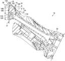
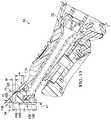
- FIG. 11is a lower front isometric view depicting the handle of FIG. 1 ;
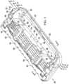
- FIG. 12is an exploded upper isometric view depicting the handle of FIG. 1 ;
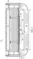
- FIG. 13is a cross-sectional view taken along the line 13 - 13 of FIG. 12 ;
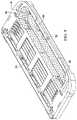
- FIG. 14is an exploded front side isometric view depicting the handle of FIG. 1 ;
- FIG. 15is an exploded lower isometric view depicting the handle of FIG. 1 ;
- FIG. 16is an exploded upper isometric view depicting the handle of FIG. 1 ;
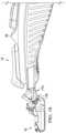
- FIG. 17is a partially exploded side view depicting the shaving system of FIG. 1 with a pivoting head of the handle and the cartridge spaced from each other;
- FIG. 18is a partially exploded side view depicting the shaving system of FIG. 17 but with the pivoting head shown more proximate to the cartridge than in FIG. 17 ;
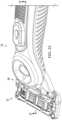
- FIG. 19is a lower side isometric view depicting the shaving system of FIG. 18 ;
- FIG. 20is a cross-sectional view taken along the line 20 - 20 of FIG. 19 ;
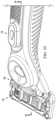
- FIG. 21is a partially exploded side view depicting the shaving system of FIG. 18 with the pivoting head shown being inserted into a handle receptacle of the cartridge;
- FIG. 22is a lower side isometric view depicting the shaving system of FIG. 21 ;
- FIG. 23is a cross-sectional view taken along the line 23 - 23 of FIG. 22 ;
- FIG. 24is a partially exploded side view depicting the shaving system of FIG. 21 but with the pivoting head shown further inserted into the handle receptacle of the cartridge;
- FIG. 25is a lower side isometric view depicting the shaving system of FIG. 24 ;
- FIG. 26is a cross-sectional view taken along the line 26 - 26 of FIG. 25 ;
- FIG. 27is a partially exploded side view depicting the shaving system of FIG. 26 but with the pivoting head shown further inserted into the handle receptacle of the cartridge;
- FIG. 28is a lower side isometric view depicting the shaving system of FIG. 27 ;
- FIG. 29is a cross-sectional view taken along the line 29 - 29 of FIG. 28 ;
- FIG. 30is a partially exploded side view depicting the shaving system of FIG. 27 but with the pivoting head shown fully installed into the handle receptacle of the cartridge;
- FIG. 31is a lower side isometric view depicting the shaving system of FIG. 30 ;
- FIG. 32is a cross-sectional view taken along the line 32 - 32 of FIG. 31 ;
- FIG. 33is a lower plane view depicting the shaving system of FIG. 27 ;
- FIG. 34is a cross-sectional view taken along the line 34 - 34 of FIG. 31 with certain components removed for clarity of illustration;
- FIG. 35is a cross-sectional view taken along the line 35 - 35 of FIG. 31 ;
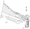
- FIG. 36is a cross-sectional view of FIG. 35 but with the handle shown in a fully pivoted position;
- FIG. 37is a partially exploded isometric view depicting a shaving system having a handle and a cartridge, in accordance with another embodiment
- FIG. 38is an upper isometric view depicting the handle of FIG. 37 ;
- FIG. 39is an isometric view depicting the cartridge of FIG. 37 .
- a shaving system 10is shown in FIG. 1 to include a cartridge 12 and a handle 14 that can cooperate to facilitate shaving of a user's skin.
- the cartridge 12can extend between a front end 16 and a rear end 18 and can include a housing 20 .
- the housing 20can include a handle interface portion 22 that is disposed at the front end 16 and defines a handle receptacle 24 that facilitates attachment of the handle 14 to the cartridge 12 .
- the housing 20can also include a blade support portion 26 that is disposed at the rear end 18 .
- the housing 20can be formed of a thermoplastic material such as polyphenylene oxide. It is to be appreciated, however, that the housing 20 can be formed of any of a variety of suitable additional or alternative materials.
- a plurality of razor blades 28can be disposed in the blade support portion 26 and can extend laterally between opposing sides 30 of the blade support portion 26 .
- the razor blades 28can be formed of stainless steel but can additionally or alternatively be formed of any of a variety of suitable materials (e.g., metals or non-metals). It is to be appreciated that although the razor blades 28 are shown to be straight razors, any of a variety of suitable alternative razor blades can be used, such as an array of rounded blades.
- the cartridge 12can also have any number of blades depending on the desired performance and cost of the cartridge 12 .
- the cartridge 12can have, for example, one razor blade, two razor blades, three razor blades, four razor blades, five razor blades, six razor blades, seven razor blades, or even more razor blades.
- the handle 14can include a main body 32 and a pivoting head 34 pivotally coupled with the main body 32 .
- the pivoting head 34can be selectively inserted into the handle receptacle 24 to facilitate coupling of the cartridge 12 and the handle 14 together.
- a usercan grasp the main body 32 of the handle 14 to facilitate shaving of the user's skin with the cartridge 12 .
- the cartridge 12can be a disposable-type cartridge that can be selectively removed from the handle 14 for replacement. Once the razor blades 28 have become dulled (or damaged) the consumer can disengage the cartridge 12 from the pivoting head 34 and replace the cartridge 12 with a new cartridge.
- the main body 32can be provided with any of a variety of suitable gripping features, such as a patterned elastomeric coating, that provides for effective gripping of the main body 32 with the user's hand.
- the handle 14can be of any suitable shape.
- the handle 14for example, can be an elongated barrel shape or can be a contoured shape.
- the handle 14can be made from any suitable material.
- the handle 14can be made, for example, from a metal, a polymer, an elastomer, a plastic, a thermoplastic, a rubber, any other suitable material, or any combination thereof.
- the handle 14can be made by any suitable process.
- the handle 14can be made, for example, by molding, injection molding, insert injection molding, casting, die-casting, extruding, any other suitable method, or any combination thereof.
- the handle 14 described hereincan additionally or alternatively include one or more features of the various embodiments of handles disclosed in co-owned, co-pending U.S. Applications having a Docket Nos. 15136P, 15137P, and 15138P which are being filed concurrently herewith and which are hereby incorporated herein by reference.
- the blade support portion 26can comprise a cap 36 and a guard 38 .
- the cap 36can be positioned behind the razor blades 28 (e.g., at the rear end 18 ) and the guard 38 can be positioned in front of the razor blades 28 (e.g., between the razor blades 28 and the handle interface portion 22 ) such that the razor blades 28 are disposed between the cap 36 and the guard 38 .
- the cap 36 and the guard 38can cooperate to define a shaving plane P 1 that is tangent to the cap 36 and the guard 38 .
- a user's skincan be positioned against the cap 36 and guard 38 such that the user's skin extends along or into the shaving plane P 1 for engagement by the razor blades 28 to facilitate shaving of the user's skin.
- the cap 36can be a separate molded or extruded component that is mounted to the housing 20 .
- the cap 36can be, for example, a shaving aid filled reservoir, an extruded lubrication strip, and/or a plastic or metal bar to support the skin and further define the shaving plane P 1 .
- the cap 36can be molded or extruded from the same material as the housing 20 or can be molded or extruded from a more lubricious shaving aid composite that has one or more water-leachable shaving aid materials to provide increased comfort during a shave stroke.
- the guard 38can extend generally parallel to the razor blades 28 and can comprise a skin-engaging member 39 for stretching the skin during a shaving stroke.
- the skin-engaging member 39is shown to be a segmented bar (e.g., that defines a plurality of fins) but can alternatively be a solid (e.g., smooth) bar.
- the skin-engaging member 39can be, for example, insert injection molded or co-injection molded to the housing. Other known assembly methods can also be used such as adhering, bonding, attaching, ultrasonic welding, or mechanical fastening.
- the skin-engaging member 39can be formed of a softer material (i.e., lower durometer hardness) than the housing 20 .
- the skin-engaging member 39can be formed of a material having a Shore A hardness of between about 20-70.
- the skin-engaging member 39can be formed of thermoplastic elastomers (TPEs) or rubbers, some examples of which can include, but are not limited to, silicones, natural rubber, butyl rubber, nitrile rubber, styrene butadiene rubber, styrene butadiene styrene (SBS) TPEs, styrene ethylene butadiene styrene (SEBS) TPEs (e.g., Kraton), polyester TPEs (e.g., Hytrel), polyamide TPEs (Pebax), polyurethane TPEs, polyolefin based TPEs, and blends of any of these TPEs (e.g., polyester/SEBS blend).
- TPEsthermoplastic elastomers
- SEBSstyrene ethylene butadiene
- the skin-engaging member 39can comprise Kraiburg HTC 1028/96, HTC 8802/37, HTC 8802/34, or HTC 8802/11 (KRAIBURG TPE GmbH & Co. KG of Waldkraiburg, Germany).
- a softer material for the skin-engaging member 39can enhance skin stretching, as well as provide a more pleasant tactile feel against the skin of the user during a shaving stroke.
- a softer materialcan also aid in masking the less pleasant feel of the harder material of the housing 20 and/or the razor blades 28 against the skin of the user during a shaving stroke.
- a trimmer assembly 40can be provided on the rear end 18 of the cartridge 12 and held in place by a pair of clips 42 .
- the trimmer assembly 40can include a blade 44 that extends away from the shaving plane P 1 and can be used for precise trimming of a user's hair (e.g., sideburns).
- the clips 42can additionally facilitate retention of the razor blades 28 to the housing 20 .
- Other assembly methods known to those skilled in the artcan additionally or alternatively be used to secure and/or mount a trimmer assembly (e.g., 40 ) and/or razor blades (e.g., 28 ) to the housing 20 including, but not limited to, wire wrapping, cold forming, hot staking, insert molding, ultrasonic welding, and adhering.
- the clips 42can be formed of a metal, such as aluminum, for example, which can facilitate conduction of heat and/or can serve as a sacrificial anode to help prevent corrosion of the razor blades 28 .
- the handle interface portion 22can include a front wall 46 , a rear wall 48 , and a pair of sidewalls 50 .
- the rear wall 48can be more proximate to the blade support portion 26 than the front wall 46 .
- the rear wall 48can be interposed between the handle interface portion 22 and the blade support portion 26 such that the rear wall 48 defines a portion of the blade support portion 26 (e.g., the handle interface portion 22 and the blade support portion 26 are immediately adjacent one another).
- the front wall 46can include a front interior surface 52
- the rear wall 48can include a rear interior surface 54
- each of the sidewalls 50can include a respective side interior surface 56 ( FIG. 4 ).
- the front wall 46can be spaced from the rear wall 48
- the sidewalls 50can extend between the front wall 46 and the rear wall 48 and can be spaced from each other such that the front interior surface 52 , the rear interior surface 54 , and the side interior surfaces 56 cooperate to define a portion of the handle receptacle 24 .
- Each of the front wall 46 , the rear wall 48 , and the sidewalls 50can include respective lower surfaces 58 , 60 , 62 .
- the lower surfaces 58 , 60 , 62can cooperate to define a lower opening 64 .
- the handle receptacle 24can extend to the lower opening 64 and the lower opening 64 can be configured to allow for insertion of the pivoting head 34 of the handle 14 into the handle receptacle 24 .
- the handle interface portion 22can include an upper surface 66 that is located on an opposite side of the cartridge 12 as the lower surfaces 58 , 60 , 62 .
- the upper surface 66can define an upper opening 68 that is more proximate the shaving plane P 1 than the lower opening 64 .
- the upper opening 68can define a perimeter M 1 .
- the perimeter M 1can be between about 45 mm and about 90 mm and preferably about 66.5 mm.
- the handle receptacle 24can extend to the upper opening 68 and can be configured to allow for a portion of the pivoting head 34 of the handle 14 to project through the upper surface 66 , as will be described in more detail below. It is to be appreciated that although the upper opening 68 is shown as an individual opening, the upper surface 66 can define any quantity of upper openings, such as, for example, a pair of upper openings.
- the lower opening 64can have a length L 1 that extends laterally along the handle interface portion 22 between the opposing sides 30 of the handle interface portion 22 . It is to be appreciated that extending laterally can be understood to mean that the length L 1 is measured in a direction that is perpendicular to the shaving direction of the cartridge 12 (e.g., the direction in which the cartridge 12 is pulled along the user's skin to facilitate shaving).
- the lower opening 64can also have a width W 1 that extends longitudinally along the handle interface portion 22 (e.g., between the front wall 46 and the rear wall 48 ).
- the upper opening 68can have a length L 2 that extends laterally along the handle interface portion 22 (e.g., between the shoulder portions 70 shown in FIG. 4 ).
- the upper opening 68can have a width W 2 that extends longitudinally along the handle interface portion 22 .
- the lower opening 64can generally be larger than the upper opening 68 .
- the length L 1 and width W 1 of the lower opening 64can be longer and wider, respectively, than the L 2 and width W 2 of the upper opening 68 .
- the length L 1 of the lower opening 64can be between about 29 mm and about 39 mm, and preferably about 34 mm
- the length L 2 of the upper opening 68can be between about 26 mm and about 36 mm, and preferably about 31 mm.
- the width W 1 of the lower opening 64can be between about 3 mm and about 8 mm, and preferably about 6.5 mm and the width W 2 of the upper opening 68 can be between about 1.5 mm and about 5 mm, and preferably about 3.6 mm.
- the relative size between the lower opening 64 and the upper opening 68can provide an intuitive pathway for installation of the pivoting head 34 into the handle receptacle 24 and can also guide the pivoting head 34 into a fully installed position within the handle receptacle 24 .
- the housing 20 of the cartridge 12can define an overall width W 0 that is measured longitudinally between the front end 16 and the rear end 18 .
- the ratio of the overall width W 0 of the housing 20 to the width W 2 of the upper opening 68can be between about 3:1 and about 2:1.
- the overall width W 0 of the housing 20can be between about 10 mm and about 11 mm.
- the front wall 46can be shorter than the rear wall 48 .
- the front wall 46can have a vertical height H 1 that is measured between the lower surface 58 of the front wall 46 (at the highest point) and the upper surface 66 .
- the rear wall 48can have a vertical height H 2 that is measured between the lower surface 60 of the rear wall 48 (at the highest point) and the upper surface 66 .
- the vertical height H 1can be less than the vertical height H 2 .
- the vertical height H 1can be between about 1.5 mm and about 7.5 mm, and preferably about 2.5 mm
- the vertical height H 2can be between about 7.5 mm and about 12 mm, and preferably about 9 mm.
- a vertical dimensione.g., a vertical distance or vertical height
- a vertical dimensioncan be understood to mean a dimension that is measured in a direction that is perpendicular to the shaving plane P 1 .
- the upper surface 66can be within a vertical distance D 1 of the shaving plane P 1 , which in some embodiments can be between about 0 mm (e.g., extending along the shave plane P 1 ) and 1 mm, and preferably about 0.25 mm to 0.5 mm. In one embodiment, as illustrated in FIG. 6 , the upper surface 66 can be spaced from the shaving plane P 1 . In other embodiments, the upper surface 66 can define the shaving plane P 1 such that the vertical distance D 1 is substantially zero.
- the proximity of the upper surface 66 to the shave plane P 1can allow the pivoting head 34 of the handle 14 to effectively contact a user's skin during shaving to provide a benefit (e.g., lubricant or heat) thereto, as will be described in further detail below.
- a benefite.g., lubricant or heat
- the handle interface portion 22can include a pair of shoulder portions 70 that each extend to the upper surface 66 and cooperate with the upper surface 66 to at least partially define the upper opening 68 .
- Each of the shoulder portions 70comprise a shoulder surface 72 that interfaces with the front interior surface 52 , the rear interior surface 54 , and one of the side interior surfaces 56 .
- the front wall 46 , the rear wall 48 , and each of the sidewalls 50cooperate to define a perimeter M 2 ( FIG. 4 ) that extends along the interface between the shoulder surface 72 and each of the front interior surface 52 , the rear interior surface 54 , and the side interior surfaces 56 .
- Each shoulder portion 70can extend laterally inwardly from the front wall 46 , the rear wall 48 , and one of the sidewalls 50 such that the perimeter M 1 of the upper opening 68 is greater than the perimeter M 2 .
- the perimeter M 2can be between about 40 mm and about 100 mm and preferably between about 60 mm and about 80 mm.
- the location of the shoulder portions 70 at the sidewalls 50can advantageously result in an overall size of the cartridge 12 that is longitudinally smaller than some conventional cartridge arrangements. All things being equal, consumers typically prefer razor cartridges that are longitudinally compact.
- the perimeter M 1 of the upper opening 68can be maximized which can enhance the contact of the pivoting head 34 with a user's skin, as will be appreciated from the additional discussion below.
- the shoulder surface 72 of one of the shoulder portions 70is shown to be spaced from the shaving plane P 1 by a vertical distance D 2 .
- the vertical distance D 2can be between about 0.5 mm and about 3 mm, and preferably about 1 mm.
- the vertical distance D 2can affect the control of the shaving geometry of the shaving system 10 and can influence the performance of the pivoting head 34 to provide benefit (e.g., heat or lubrication) to the skin through the upper opening 68 , as will be described in further detail below.
- benefite.g., heat or lubrication
- the handle interface portion 22can include a front lip portion 74 that extends between the front wall 46 and the upper surface 66 and between the shoulder portions 70 .
- the front lip portion 74can include a lip surface 76 ( FIGS. 2 and 6 ) that extends between the front interior surface 52 and the upper surface 66 .
- the lip surface 76can be non-coplanar with the front interior surface 52 of the front wall 46 .
- the lip surface 76can extend along a plane P 2 and the front interior surface 52 can extend along a plane P 3 that is non-coplanar (e.g., angled) with respect to the plane P 2 .
- the lip surface 76can be arranged such that the plane P 2 is substantially perpendicular to the shaving plane P 1 .
- the front lip portion 74can be configured to engage the pivoting head 34 of the handle 14 .
- the rear wall 48can include a central portion 78 and a pair of distal portions 80 ( FIG. 7 ) that each extend from the central portion 78 to one of the sidewalls 50 .
- the rear wall 48can be thinner at the distal portions 80 than at the central portion 78 such that each of the distal portions 80 defines a notch 82 .
- the central portion 78can have a thickness T 1 and each of the distal portions 80 can have a thickness T 2 .
- the thickness T 1 of the central portion 78can be greater than the thickness T 2 of the distal portions 80 .
- the ratio of the first thickness T 1 to the second thickness T 2can be about 3:1 to about 3:2.
- the thickness T 1can be between about 0.75 mm and about 3 mm, and preferably between about 1 mm and 2 mm, and the thickness T 2 can be between about 0.5 mm and about 1 mm, and preferably between about 0.6 mm to 0.8 mm.
- each of the central portion 78 and the distal portions 80can result in the rear interior surface 54 of the rear wall 48 at the distal portions 80 being spaced further from the front interior surface 52 of the front wall 46 than the rear interior surface 54 at the central portion 78 of the rear wall 48 .
- the rear interior surface 54 at the central portion 78 of the rear wall 48can be spaced from the front interior surface 52 by a horizontal distance D 3 .
- the rear interior surface 54 at the distal portion 80can be spaced from the front interior surface 52 by a horizontal distance D 4 that is greater than the horizontal distance D 3 .
- a horizontal distancecan be understood to mean that a distance that is measured in a direction that is parallel to the shaving plane P 1 .
- each of the distal portions 80might define an alternative notch (not shown) that only extends partially between the lower surface 60 and one of the shoulder portions 70 such that the notches are configured as recesses. It is also to be appreciated that while the notches 82 are described as being similar to each other, it is contemplated that the notches can alternatively be configured differently from each other.
- the rear interior surface 54 located at the central portion 78 of the rear wall 48can extend to the upper surface 66 ( FIG. 6 ) and between the shoulder portions 70 and can be spaced from the lip surface 76 ( FIG. 6 ). As illustrated in FIG. 6 , the rear interior surface 54 can extend along a plane P 4 . In one embodiment, the plane P 4 can be substantially perpendicular to the shaving plane P 1 .
- each of the front corners 84can be configured to selectively flex relative to adjacent portions of the front wall 46 and the sidewalls 50
- each of the rear corners 86can be configured to selectively flex relative to adjacent portions of the rear wall 48 and the sidewalls 50 .
- each of the front corners 84can have a moment of inertia that is less than the moment of inertia of the adjacent portions of the front wall 46 and the sidewalls 50
- each of the rear corners 86can have a moment of inertia that is less than the moment of inertia of the adjacent portions of the rear wall 48 and the sidewalls 50
- each of the front corners 84 and the rear corners 86can have a moment of inertia that is less than about 2 mm 4 .
- the higher flexibility of the front and rear corners 84 , 86can allow the front and rear corners 84 , 86 to effectively serve as frangible areas for when the cartridge 12 undergoes significant impact, such as when the shaving system 10 is dropped.
- the front and rear corners 84 , 86can be configured to break first when the cartridge 12 undergoes significant impact to prevent the blade support portion 26 from breaking and allowing the razor blades 28 to separate from the cartridge 12 .
- any quantity (e.g., one, two, or three) and/or combination of the front and rear corners 84 , 86are contemplated to have a higher flexibility.
- the front interior surface 52 of the front wall 46 and the rear interior surface 54 of the central portion 78 of the rear wall 48can be tapered inwardly towards the upper opening 68 such that the handle receptacle 24 is generally funnel-shaped below the shoulder portions 70 .
- the front interior surface 52 and the rear interior surface 54 of the central portion 78 of the rear wall 48can be angled relative to each other such that the planes P 3 , P 4 intersect at an included angle ⁇ 1 (any angle that is less than 180 degrees) to define the funnel-shape of the handle receptacle 24 .
- the included angle ⁇ 1can be between about 30 degrees and 70 degrees, and preferably between about 45 degrees and about 48 degrees.
- the included angle ⁇ 1can provide the front wall 46 and the rear wall 48 at an angle that narrows the handle receptacle 24 in the direction of the upper opening 68 to provide an intuitive pathway for installation of the pivoting head 34 through the lower opening 64 and can also guide the pivoting head 34 into a fully installed position within the handle receptacle 24 .
- the front interior surface 52 of the front wall 46 and the rear interior surface 54 of the central portion 78 of the rear wall 48can be generally planar such that the front interior surface 52 of the front wall 46 and the rear interior surface 54 of the central portion 78 of the rear wall 48 reside substantially entirely in the front and rear planes P 3 , P 4 , respectively.
- alternative non-planar surfacesare contemplated, such as, for example, surfaces that have at least one contoured area.
- the term extending in a planecan be understood to mean that the surface has at least two points that reside in the plane.
- the rear interior surface 54 of the central portion 78 of the rear wall 48is discussed, any other portion of the rear interior surface 54 is also contemplated as defining the funnel shape of the handle receptacle 24 .
- the funnel-shape of the handle receptacle 24can result in the cross-sectional surface area of the handle receptacle 24 being larger proximate the lower opening 64 than proximate the upper opening 68 .
- an upper cross-sectional area A 1can be defined by each of the front interior surface 52 , the rear interior surface 54 , and the side interior surfaces 56 proximate the upper opening 68 .
- a lower cross-sectional area A 2can be defined by each of the front interior surface 52 , the rear interior surface 54 , and the side interior surfaces 56 at the lower opening 64 .
- the upper cross-sectional area A 1can be more proximate the upper opening 68 than the lower cross-sectional area A 2 .
- the upper cross-sectional area A 1can be taken at a vertical distance of about 1 mm from the shaving plane P 1 .
- an intermediate cross-sectional area A 3can be defined by each of the front interior surface 52 , the rear interior surface 54 , and the side interior surfaces 56 and can be disposed between the upper cross-sectional area A 1 and the lower cross-sectional area A 2 .
- the lower cross-sectional area A 2can be greater than the upper cross-sectional area A 1 .
- the intermediate cross-sectional area A 3can be less than the lower cross-sectional area A 2 and greater than the upper cross-sectional area A 1 .
- the lower cross-sectional area A 1can be between about 60 mm 2 and about 250 mm 2 , and preferably about 155 mm 2 and the upper cross-sectional area A 2 can be between about 40 mm 2 and about 120 mm 2 , preferably about 80 mm 2 .
- the upper cross-sectional area A 1can be understood to mean the smallest cross-sectional area that can be defined by each of the front interior surface 52 , the rear interior surface 54 , and the side interior surfaces 56 that is taken at a cross-section that is parallel to the shaving plane P 1 .
- the lower cross-sectional area A 2can be understood to mean the largest cross-sectional area that can be defined by each of the front interior surface 52 , the rear interior surface 54 , and the side interior surfaces 56 that is taken at a cross-section that is parallel to the shaving plane P 1 .
- the handle interface portion 22can include a locking member 88 that is configured to facilitate selective retention of the pivoting head 34 ( FIG. 1 ) of the handle 14 within the handle receptacle 24 .
- the locking member 88can comprise a central member 90 , a pair of support arms 92 and a deflection member 94 .
- Each of the central member 90 and the support arms 92can be coupled with the central portion 78 of the rear wall 48 and can extend from the rear wall 48 .
- the deflection member 94can comprise a pair of distal members 96 and a central portion 98 that is interposed between the distal members 96 .
- the central member 90can be coupled with the central portion 98 and each of the distal members 96 can be coupled with one of the support arms 92 .
- each of the central member 90 and the support arms 92can extend from the rear wall 48 such that the deflection member 94 is interposed between the front wall 46 and the plane P 4 of the rear interior surface 54 of the rear wall 48 .
- the locking member 88can accordingly extend from the rear interior surface 54 of the central portion 78 of the rear wall 48 towards the front wall 46 such that the locking member 88 overhangs the rear wall 48 .
- the locking member 88can extend from the rear interior surface 54 at the central portion 78 of the rear wall 48 and towards the front wall 46 by a horizontal distance D 5 that is between about 1 mm and 3 mm, and preferably between about 1.5 mm and 2.5 mm.
- the locking member 88can engage the pivoting head 34 to facilitate retention of the pivoting head 34 in the handle receptacle 24 .
- the deflection member 94can include an upper surface 100 ( FIGS. 5 and 6 ) that is spaced from the lower surface 60 of the rear wall 48 such that the central member 90 , the support arms 92 , the upper surface 100 and the lower surface 60 cooperate to define a pair of slots 102 ( FIGS. 4 and 5 ) that extend between the rear wall 48 and the deflection member 94 .
- the upper surface 100 of the deflection member 94 and the rear interior surface 54 at the central portion 78 of the rear wall 48e.g., the plane P 4
- the cartridge 12 disclosed hereincan additionally or alternatively include one or more features of the various embodiments of the cartridges disclosed in co-owned, co-pending U.S. Applications having Docket Nos. 15140P, 15141P, 15142P, 15143P, 15144P, 15145P, 15146P, 15147P, and 15160P which are being filed concurrently herewith and which are hereby incorporated herein by reference.
- the pivoting head 34 of the handle 14can be configured for insertion into the handle receptacle 24 ( FIG. 1 ) to facilitate releasable attachment of the handle 14 with the cartridge 12 .
- the pivoting head 34can extend between an upper end 104 and a lower end 106 .
- the pivoting head 34can comprise a base member 108 and a cover member 110 that is coupled with the base member 108 .
- the handle 14can comprise a pair of arms 112 that are each spaced from one another and extend from the main body 32 and to the lower end 106 of the pivoting head 34 . Each of the arms 112 can be rigidly coupled with the main body 32 of the handle 14 .
- Each of the arms 112can comprise a pin member 113 (also shown in FIGS. 14 and 34 ).
- Each of the pin members 113can be pivotally coupled with the base member 108 such that the pivoting head 34 is pivotable about a pivot axis A 1 defined by the pin members 113 .
- a springe.g., 156 in FIG. 34
- the handle 14can provide one or more pivot motions for the pivoting head 34 .
- the pivot axis A 1can be generally transverse to the handle 14 .
- the handle 14is shown to include a pair of arms 112 , it is to be appreciated that a handle can be provided with any other quantity of arms such as one arm or more than two arms.
- the front wall 114 and the rear wall 116are angled with respect to each other and cooperate with each other define a pair of V-shaped grooves 128 (one shown) at the side exterior surfaces 122 , 126 .
- the arms 112can extend along the V-shaped grooves 128 and can be configured to travel within the V-shaped grooves 128 when the pivoting head 34 is pivoted.
- the head portion 118can comprise a face surface 130 that defines a pair of apertures 132 .
- the apertures 132can be in fluid communication with a fluid distribution system that facilitates dispensation of shaving fluid, such as, for example, shaving cream or shaving lotion.
- the fluid distribution systemcan comprise a reservoir 136 , a dispensing button 138 , and a fluid delivery member 140 .
- the reservoir 136can be in fluid communication with the fluid delivery member 140 which can be in fluid communication with the apertures 132 ( FIG. 12 ) of the head portion 118 .
- the dispensing button 138can be fluidly interposed between the reservoir 136 and the fluid delivery member 140 and can be configured to facilitate selective dispensation of the shaving fluid stored in the reservoir 136 through the apertures 132 ( FIG. 12 ). In particular, a user can depress the dispensing button 138 while shaving to dispense the shaving fluid to the user's skin.
- Suitable skin lubricating water-soluble polymerscan include polyethylene oxide, polyvinyl pyrrolidone, polyacrylamide, hydroxypropyl cellulose, polyvinyl imidazoline, and polyhydroxyethylmethacrylate.
- Other water-soluble polymerscan include the polyethylene oxides generally known as POLYOX (available from Union Carbide Corporation) or ALKOX (available from Meisei Chemical Works, Kyota, Japan). These polyethylene oxides can have molecular weights of about 100,000 to 6 million, for example, about 300,000 to 5 million.
- the polyethylene oxidecan comprise a blend of about 40 to 80% of polyethylene oxide having an average molecular weight of about 5 million (e.g., POLYOX COAGULANT) and about 60 to 20% of polyethylene oxide having an average molecular weight of about 300,000 (e.g., POLYOX WSR-N-750).
- the polyethylene oxide blendcan also contain up to about 10% by weight of a low molecular weight (i.e., molecular weight of less than about 10,000) polyethylene glycol such as PEG-100.
- the shaving fluidcan also include a complex of a skin-soothing agent with a cylcodextrin, low molecular weight water-soluble release enhancing agent such as polyethylene glycol (e.g., 1-10% by weight), water-swellable release enhancing agents such as cross-linked polyacrylics (e.g., 2-7% by weight), colorants, antioxidants, preservatives, microbicidal agents, beard softeners, astringents, depilatories, medicinal agents, conditioning agents, moisturizers, cooling agents, and the like.
- a skin-soothing agent with a cylcodextrinlow molecular weight water-soluble release enhancing agent such as polyethylene glycol (e.g., 1-10% by weight), water-swellable release enhancing agents such as cross-linked polyacrylics (e.g., 2-7% by weight), colorants, antioxidants, preservatives, microbicidal agents, beard softeners, astringents, dep
- the head portion 118can comprise an exterior lip surface 146 that extends between the front and rear walls 114 , 116 and the face surface 130 .
- the front wall 114 and the head portion 118can be angled with respect to each other such that the front exterior surface 120 and the exterior lip surface 146 are non-coplanar.
- the exterior lip surface 146can extend along a plane P 5
- the front exterior surface 120 of the front wall 114can extend along a plane P 6 that is non-coplanar with the plane P 5 .
- Each of the exterior lip surface 146 and the front exterior surface 120can be generally planar such that the exterior lip surface 146 and the front exterior surface 120 reside substantially entirely in the plane P 6 .
- the angle of the front exterior surface 120 and the exterior lip surface 146can generally correspond to the angle between the front wall 46 and the front lip portion 74 of the cartridge 12 (e.g., the angle between plane P 2 and P 3 shown in FIG. 6 ) to allow for proper insertion of the pivoting head 34 into the handle receptacle 24 .
- the head portion 118can have a vertical height H 3 that can be between about 0.5 mm and about 2 mm, and preferably between about 0.9 mm and about 1.0 mm. It is to be appreciated that a vertical dimension (e.g., height or distance) on the handle 14 can be understood to mean that the dimension is measured in a direction that is perpendicular to the shaving plane P 1 when the pivoting head 34 is installed on the cartridge 12 .
- the front wall 114can have a vertical height H 4 that can be between about 1.5 and about 5 mm, and preferably about 3.1 mm.
- the rear wall 116can have a vertical height H 5 that can be between about 5.5 mm and about 12 mm, and preferably between about 7 mm and about 9 mm.
- the rear wall 116can include a central portion 148 and a pair of tab members 150 that are disposed at opposite ends of the central portion 148 .
- the tab members 150can be thicker than the central portion 148 such that the tab members 150 protrude longitudinally (e.g., rearwardly) relative to the central portion 148 .
- the central portion 148can have a thickness T 3 and each of the tab members 150 can have a thickness T 4 that is greater than the thickness T 3 of the central portion 148 .
- the ratio of the thickness T 4 to the thickness T 3can be between about 3:1 and about 3:2.
- the thickness T 4can be between about 0.75 mm and about 3 mm, and preferably about 0.9 mm to about 1.0 mm, and the thickness T 3 can be between about 0.5 mm and about 1 mm, and preferably between about 0.8 mm to about 0.9 mm.
- the tab members 150are shown in FIG. 14 to extend substantially entirely between the lower end 106 of the pivoting head 34 and the head portion 118 . However, it is to be appreciated that other tab member configurations are contemplated. For example, tab members might only extend partially between the lower end 106 of the pivoting head 34 and the head portion 118 such that they are spaced from one or more of the lower end 106 of the pivoting head 34 and the head portion 118 . It is also to be appreciated that while the tab members 150 are described as being similar to each other, it is contemplated that tab members can alternatively be configured differently from each other.
- the head portion 118can have a length L 3 that extends laterally along the pivoting head 34 .
- the head portion 118can also have a width W 3 that extends longitudinally along the pivoting head 34 .
- the length L 3 and the width W 3 of the head portion 118can be slightly smaller than the length L 2 and the width W 2 of the upper opening 68 ( FIG. 5 ) to allow the head portion 118 to fit within the upper opening 68 when the pivoting head 34 is installed in the handle receptacle 24 .
- the pivoting head 34can comprise a pair of shoulder portions 152 that each extend laterally between the front wall 114 , the rear wall 116 , and the head portion 118 and are each disposed on opposite sides of the head portion 118 .
- Each of the shoulder portions 152comprise a shoulder surface 154 that interfaces with a portion of each of the front exterior surface 120 , the side exterior surfaces 122 , the rear exterior surface 124 , the side exterior surfaces 126 , and the exterior lip surface 146 .
- the front exterior surface 120 of the front wall 114 and the rear exterior surface 124 of the central portion 148 of the rear wall 116can be tapered inwardly towards the head portion 118 such that the pivoting head 34 is generally funnel-shaped below the shoulder portions 152 .
- the front exterior surface 120 and the rear exterior surface 124 of the central portion 148 of the rear wall 116can be angled relative to each other such that the planes P 6 , P 7 intersect at an included angle ⁇ 3 (any angle that is less than 180 degrees) to define the funnel-shape of the pivoting head 34 .
- the included angle ⁇ 2can be between about 30 degrees and 70 degrees, and preferably between about 45 degrees and about 48 degrees.
- the funnel-shape of the pivoting head 34 below the shoulder portions 152can correspond to the funnel shape of the handle receptacle 24 such that the pivoting head 34 fits snugly in the handle receptacle 24 when the pivoting head 34 is inserted into the handle receptacle 24 .
- the pivoting head 34can have a lower length L 4 at the lower end 106 that extends laterally and is defined by the front wall 114 and the rear wall 116 .
- the pivoting head 34can also have a lower width W 4 at the lower end 106 that extends longitudinally and is defined by the front wall 114 and the rear wall 116 .
- the pivoting head 34can have an upper length L 5 at the upper end 104 that extends laterally and is defined by the front wall 114 and the rear wall 116 .
- the pivoting head 34can also have an upper width W 5 at the upper end 104 that extends longitudinally and is defined by the front wall 114 and the rear wall 116 .
- the lower end 106 of the pivoting head 34can generally be larger than the upper end 104 .
- the lower length L 4 and the lower width W 4 of the pivoting head 34 at the lower end 106can be longer and wider, respectively, than the upper length L 5 and the upper width W 5 of the pivoting head 34 at the upper end 104 .
- the lower length L 4can be between about 25 mm and about 55 mm, and preferably about 35 mm
- the lower width W 4can be between about 3 mm and about 8 mm, and preferably about 3.9 mm.
- the upper length L 5can be between about 20 mm and about 40 mm, and preferably about 30 mm
- the upper width W 5can be between about 1 mm and about 6 mm, and preferably about 3.4 mm.
- the handle 14can be positioned with the pivoting head 34 adjacent to the front end 16 of the housing 20 and with the pivoting head 34 tilted downwardly such that the face surface 130 is angled relative to the shaving plane P 1 .
- the main body 32 of the handle 14can be laid substantially flat (e.g., substantially parallel to the shaving plane P 1 ) to provide the pivoting head 34 in such a position. As illustrated in FIGS.
- the handle 14can then be moved towards the cartridge 12 proximate the handle receptacle 24 .
- the vertical height H 1 of the front wall 46can be shorter than the vertical height H 2 of the rear wall 48 .
- the front wall 46can provide sufficient clearance for inserting the pivoting head 34 into the handle receptacle 24 from the front of the cartridge 12 .
- the pivoting head 34can pass over the front wall 46 and into the handle receptacle 24 while remaining spaced from the rest of the cartridge 12 (e.g., the locking member 88 ).
- the handle 14can then be moved further towards the cartridge 12 and pivoted slightly upwardly to further insert the pivoting head 34 into the handle receptacle 24 ( FIG. 23 ).
- the front wall 114 and the head portion 118 of the pivoting head 34are shown in FIG. 23 to contact the front wall 46 to facilitate guiding of the pivoting head 34 into the handle receptacle 24 .
- the rear wall 116can alternatively contact the locking member 88 to facilitate guidance of the pivoting head 34 into the handle receptacle 24 .
- the side exterior surfaces 122 , 126 of the front wall 114 and the rear wall 116shown in FIG.
- the pivoting head 34can eventually contact each of the front wall 46 and the rear wall 48 , as illustrated in FIGS. 24 - 26 .
- the front wall 46 and the rear wall 48can deflect, as illustrated in FIGS. 27 - 29 .
- the deflection of the front and rear walls 46 , 48can be facilitated by the flexibility of the front and rear corners 84 , 86 ( FIG. 7 ) described above. It is to be appreciated that although both the front and rear walls 46 , 48 are shown to deflect, only one of the front wall 46 or the rear wall 48 might deflect to allow for insertion of the pivoting head 34 into the handle receptacle 24 .
- the pivoting head 34can be further inserted into the handle receptacle 24 (e.g., by continuing to move the handle 14 further towards the cartridge 12 and/or by pivoting the handle 14 further upwardly) until the pivoting head 34 is fully installed in the handle receptacle 24 , as illustrated in FIGS. 30 - 32 .
- FIG. 32when the pivoting head 34 is fully installed in the handle receptacle 24 ( FIG. 17 ), the front and rear walls 46 , 48 are no longer deflected and the locking member 88 overhangs the rear wall 116 and a portion of the cover member 110 .
- the angle ⁇ 2 ( FIG. 6 ) of the locking member 88can effectively angle the locking member 88 towards the pivoting head 34 .
- the portions of the cover member 110 and the rear wall 116 that are disposed above the locking member 88can have an angled shape that corresponds with the angle ⁇ 2 of the locking member 88 .
- the angle ⁇ 2 of the locking member 88can effectively enhance the securement of the pivoting head 34 within the handle receptacle 24 by discouraging inadvertent separation of the cartridge 12 from the handle 14 .
- the angle ⁇ 2 of the locking member 88can also facilitate effective retention of the pivoting head 34 to the cartridge 12 when the trimmer assembly 40 is used to shave a user's skin.
- the cartridge 12does not comprise a pivot mechanism in and of itself.
- the interface between the cartridge 12 and the handle 14does not comprise a pivot mechanism in and of itself.
- the pivoting head 34 and the cartridge 12are selectively locked together and while they do not pivot relative to one another, they pivot together relative to the handle 14 about the pivot axis A 1 ( FIG. 11 ).
- the overall funnel-shape of the handle receptacle 24 described abovecan correspond to the trapezoidal prism-shape of the pivoting head 34 described above such that pivoting head 34 nests within the handle receptacle 24 when fully installed.
- the front and rear walls 114 , 116 of the pivoting head 34can be seated against the front and rear walls 46 , 48 of the cartridge 12 , respectively.
- the side exterior surfaces 122 , 126 of the front and rear walls 114 , 116( FIG. 16 ), respectively, can be seated against the sidewalls 50 .
- Such nesting of the pivoting head 34 within the handle receptacle 24can enhance the securement of the pivoting head 34 to the cartridge 12 to inhibit any undesired movement therebetween during shaving.
- the relative shapes of the handle receptacle 24 and the pivoting head 34can result in a tight fit between the cartridge 12 and the pivoting head 34 which can provide smaller gaps between the cartridge 12 and the pivoting head 34 by virtually eliminating the small radii and abrupt corners that are difficult to manufacture in the mating surfaces of two components. These smaller gaps provide for a more comfortable skin contacting surface during shaving by preventing areas where hair or other shave debris can be trapped, especially around tight places, such as the neck and underarms.
- the head portion 118 of the pivoting head 34can project at least partially into the upper opening 68 such that the head portion 118 is exposed at the upper surface 66 and to a user's skin at the shaving plane P 1 .
- the head portion 118can contact the user's skin to distribute any shaving fluid dispensed from the apertures 132 ( FIG. 12 ) to the user's skin ahead of the razor blades 28 .
- the shaving fluidcan accordingly lubricate the skin prior to being shaved by the razor blades 28 .
- the shaving system 10can accordingly be configured to deliver benefits (e.g., lubrication) to the user's skin by extending the head portion 118 of the pivoting head 34 through the upper opening 68 ( FIG. 5 ).
- the head portion 118can project through the upper opening 68 such that the face surface 130 protrudes from the upper surface 66 and is spaced from the upper surface 66 by a vertical distance D 6 .
- the vertical distance D 6can be substantially similar to the vertical distance D 1 described above with respect to FIG. 6 such that the face surface 130 extends along the shaving plane P 1 .
- the vertical distance D 6can be between about 0.25 mm and about 1 mm, and preferably about 0.5 mm.
- the vertical distance D 6can be selected to be greater than or less than the vertical distance D 1 such that the face surface 130 is disposed respectively above or below the shaving plane P 1 .
- the head portion 118 of the pivoting head 34can project into the upper opening 68 such that the face surface 130 is substantially flush with the upper surface 66 . In yet another embodiment, the head portion 118 of the pivoting head 34 can project partially into the upper opening 68 such that the head portion 118 is recessed within the upper opening 68 . It is to be appreciated that location of the face surface 130 relative to the shaving plane P 1 can be determined by the relative distance D 2 ( FIG. 6 ) between the shoulder surface 72 and the shaving plane P 1 and the vertical height H 3 ( FIG. 13 ) of the head portion 118 .
- the rear wall 116 of the pivoting head 34can be seated against the rear wall 48 of the cartridge 12 such that the tab members 150 of the pivoting head 34 extend into respective ones of the notches 82 of the rear wall 48 .
- the tab members 150can each define a length L 6 and the pin members 113 can each define a length L 7 that is less than the length L 6 of the tab members 150 .
- the pin members 113can be spaced from each other by a distance D 7 .
- the central portion 148 of the rear wall 116can have a length L 8 that extends laterally and is less than the distance D 7 .
- the pin members 113 of the arms 112can be disposed within respective ones of the tab members 150 which can allow the pin members 113 to be located nearer to the blade support portion 26 than would be possible at the central portion 148 of the rear wall 116 .
- the pivot axis A 1 defined by the pin members 113can be spaced from the nearest razor blade 28 by a distance D 8 which can be less than conventional arrangements and without sacrificing the structural integrity achieved by those conventional arrangements.
- the location of the pivot axis A 1 relatively close to the nearest shaving blade 28can allow the cartridge 12 to follow the skin more closely during a shave stroke and with less blade tip pressure thereby providing a smoother, more comfortable, and more effective shave.
- the distance D 8can be between about 0.7 mm and about 2.5 mm and preferably about 2.0 mm and more preferably about 1.5 mm.
- the handle 14can pivot about the pivot axis A 1 relative to the cartridge 12 between a home position as illustrated in FIG. 35 and a fully pivoted position as illustrated in FIG. 36 to allow the cartridge 12 to contour to the user's skin.
- the arms 112can travel within the V-shaped grooves 128 to allow for pivoting of the pivoting head 34 and thus the cartridge 12 between the home position and the fully pivoted position.
- the V-shaped grooves 128can define the pivot limits of the home position and the fully pivoted position of the pivoting head 34 .
- a spring 156as illustrated in FIG. 34 , can be disposed between the base member 108 and the cover member 110 ( FIG. 11 ) and can comprise a pair of arms 158 ( FIG.
- the spring 156can bias the pivoting head 34 into the home position such that when a user shaves with the shaving system 10 , the spring 156 can maintain contact between the cartridge 12 and the user's skin. It is to be appreciated that the pivot limits and biasing can be accomplished by any means known in the art, including mechanical limits.
- the handle 14can comprise an ejection button 160 that is slidable between a retracted position (shown in solid lines) and an extended position (shown in dashed lines).
- the ejection button 160can be slid from the retracted position to the extended position to facilitate ejection of the cartridge 12 from the handle 14 .
- the ejection button 160can be biased into the retracted position.
- the usercan push the ejection button 160 towards the extended position and into contact with the deflection member 94 of the locking member 88 .
- the usercan further urge the ejection button 160 towards the extended position until the pivoting head 34 is out of engagement with the locking member 88 (e.g., into the position shown in FIGS. 27 - 29 ) and can be removed from the cartridge 12 .
- the ejection button 160can be spaced from the locking member 88 by a distance D 9 that is sufficient to prevent interference between the ejection button 160 and the locking member 88 when the cartridge 12 is pivoted into the fully pivoted position, as illustrated in FIG. 36 .
- the distance D 9can be between about 2.0 mm and about 5.0 mm and preferably about 3.0 mm.
- FIGS. 37 and 38illustrate an alternative embodiment of a shaving system 1010 that includes a cartridge 1012 and a handle 1014 that can be similar to, or the same as in many respects as, the cartridge 12 and the handle 14 , respectively, illustrated in FIGS. 1 - 36 .
- the cartridge 1012can comprise a plurality of razor blades 1028 .
- the handle 1014can comprise a main body 1032 and a pivoting head 1034 pivotally coupled with the main body 1032 .
- the pivoting head 1034can be configured for releasable attachment to the cartridge 1012 in a similar manner as described above with respect to FIGS. 1 - 36 .
- the pivoting head 1034can comprise a head portion 1118 .
- the head portion 1118can comprise a heating element 1162 ( FIG. 38 ) that is in electrical communication with a heating system 1164 ( FIG. 37 ).
- the heating system 1164can comprise a power storage device 1166 and a heating controller 1168 that is in electrical communication with the power storage device 1166 .
- a power button 1170can be in electrical communication with the heating element 1162 and the heating controller 1168 .
- the power button 1170can be configured to facilitate selective energization of the heating element 1162 . When the power button 1170 is activated (e.g., depressed), power can be delivered from the power storage device 1166 to the heating element 1162 to generate heat from the heating element 1162 .
- the heating controller 1168can regulate the power flow from the power storage device 1166 to the heating element 1162 to regulate the amount of heat generated by the heating element 1162 .
- the power storage device 1166can comprise a rechargeable battery that can be recharged with a power cord or through inductive charging.
- the power storage device 1166can comprise a disposable battery.
- the head portion 1118can contact the user's skin to heat the user's skin ahead of the razor blades 1028 . As the user pulls the cartridge 1012 across their skin, the heat can soften the skin prior to being shaved by the razor blades 1028 .
- the heating element 1162can comprise a metal such as aluminum or stainless steel. In certain embodiments, the heating element 1162 can comprise a high capacity material such as metal or phase change materials.
- the heating element 1162can comprise high thermal conductivity materials such as copper, aluminum, or thermally conductive plastics such as CoolPoly® (trademark symbol). It is to be appreciated that although the pivoting head 1034 is described as selectively heating a user's skin, the pivoting head 1034 can additionally or alternatively be configured to facilitate selective cooling of the user's skin. In some embodiments, heating or cooling delivered by the pivoting head 1034 can also be achieved passively such as by dipping or running the pivoting head 1034 under water at a different temperature than ambient.
- the cartridge 1012can be similar to, or the same as in many respects as, the cartridge 12 , illustrated in FIGS. 1 - 36 .
- the cartridge 1012can comprise a rear wall 1048 that partially defines a lower opening 1064 and an upper opening 1068 .
- the cartridge 1012can comprise a pair of locking members 1088 that are spaced from each other and extend from the rear wall 1048 about midway between the lower opening 1064 and the upper opening 1068 .
- the handlecan weigh two to three times more than most wet shaving razor systems commonly found on the market. For instance, most conventional shaving razor handles weigh less than 56 grams, and the vast majority weighs less than 45 grams.
- the handles (e.g., 14 , 1014 ) of the present disclosurecan have a mass up to about 120 grams with preferred mass of about 80 grams. In some embodiments, the handle (e.g., 14 , 1014 ) can have a mass of about 57 grams to about 150 grams and more preferably about 80 grams. Such a mass is considered “heavy” in the present disclosure.
- the handle 14 shown in FIGS. 1 and 11 - 16can have a mass about 75 grams and the handle 1014 shown in FIGS. 37 and 38 has a mass of about 85 grams.
- a shaving razor cartridgecomprising:
- a housingthat extends between a front end and a rear end, the housing comprising:
- first sidewall and the second sidewallare spaced from each other and extend between the front wall and the rear wall such that the front wall, the rear wall, the first sidewall, and the second sidewall cooperate to define the handle receptacle;
- an intermediate cross-sectional areais defined by the handle receptacle between the upper opening and the lower opening and is taken at a cross-section that is parallel to the shaving plane;
- the intermediate cross-sectional areais less than the lower cross-sectional area and is greater than the upper cross-sectional area.
- the at least one razor bladeextends laterally between opposing sides of the blade support portion
- the upper openinghas a first length that extends laterally along the handle interface portion
- the lower openinghas a second length that extends laterally along the handle interface portion
- the first lengthis greater than the second length.
- the shaving razor cartridge of Paragraph Hwherein the first length is between about 29 mm and about 39 mm and the second length is between about 26 mm and about 36 mm.
- the at least one razor bladeextends laterally between opposing sides of the blade support portion
- the lower openinghas a first width that extends longitudinally along the handle interface portion
- the upper openinghas a second width that extends longitudinally along the handle interface portion
- the first widthis greater than the second width.
- the handle interface portionfurther comprises a first sidewall comprising a lower surface and an interior surface;
- the handle interface portionfurther comprises a second sidewall comprising a lower surface and an interior surface;
- the first sidewall and the second sidewallare spaced from each other and extend between the front wall and the rear wall such that the front wall, the rear wall, the first sidewall, and the second sidewall cooperate to define the handle receptacle;
- the respective interior surfaces of the first sidewall and the second sidewallare tapered inwardly towards the upper opening.
- a shaving razor cartridgecomprising:
- a housingthat extends between a front end and a rear end, the housing comprising:
- the handle interface portioncomprises an upper surface that defines an upper opening
- the handle receptacleextends between the lower opening and the upper opening
- the upper openingis more proximate to the shaving plane than the lower opening.
- the at least one razor bladeextends laterally between opposing sides of the blade support portion
- the upper openinghas a first length that extends laterally along the handle interface portion
- the lower openinghas a second length that extends laterally along the handle interface portion
- the first lengthis greater than the second length.
- TThe shaving razor cartridge of Paragraph S wherein the first length is between about 29 mm and about 39 mm and the second length is between about 26 mm and about 36 mm.
- the at least one razor bladeextends laterally between opposing sides of the blade support portion
- the lower openinghas a first width that extends longitudinally along the handle interface portion
- the upper openinghas a second width that extends longitudinally along the handle interface portion
- the first widthis greater than the second width.
- the shaving razor cartridge of Paragraph Rwherein the first width is between about 3 mm and about 8 mm and the second width is between about 1.5 mm and about 5 mm.
- a shaving razor cartridgecomprising:
- a housingthat extends between a front end and a rear end, the housing comprising:
- At least one razor bladedisposed in the blade support portion between the cap and the guard, the at least one razor blade extending laterally between opposing sides of the blade support portion, wherein:
- the first sidewall and the second sidewallare spaced from each other and extend between the front wall and the rear wall such that the front wall, the rear wall, the first sidewall, and the second sidewall cooperate to define the handle receptacle;
- the respective interior surfaces of the first sidewall and the second sidewallare tapered inwardly towards the upper opening.
- the lower openinghas a first width that extends longitudinally along the handle interface portion
- the upper openinghas a second width that extends longitudinally along the handle interface portion
- the first widthis greater than the second width.
- the shaving razor cartridge of Paragraph AIwherein the first width is between about 3 mm and about 8 mm and the second width is between about 1.5 mm and about 5 mm.
- the shaving razor cartridge of Paragraph AJwherein the first width is about 6.5 mm and the second width is about 3.6 mm.
- the shaving razor cartridge of Paragraph AMwherein the upper surface is disposed between the shaving plane and the lower surfaces.
- a shaving razor cartridgecomprising:
- a housingthat extends between a front end and a rear end, the housing comprising:
- At least one razor bladedisposed in the blade support portion between the cap and the guard, the at least one razor blade extending laterally between opposing sides of the blade support portion, wherein:
- the first sidewall and the second sidewallare spaced from each other and extend between the front wall and the rear wall such that the front wall, the rear wall, the first sidewall, and the second sidewall cooperate to define the handle receptacle;
- the respective interior surfaces of the first sidewall and the second sidewallare tapered inwardly towards the upper opening.
- the interior surface of the front wallextends along a front plane
- the interior surface of the rear wallextends along a rear plane
- the front plane and the rear planeintersect at an included angle.
- the shaving razor cartridge of Paragraph AU wherein the included angleis between about 30 degrees and about 70 degrees.
- the shaving razor cartridge of Paragraph AVwherein the included angle is between about 45 degrees and about 48 degrees.
- a shaving razor cartridgecomprising:
- a housingthat extends between a front end and a rear end, the housing comprising:
- the handle interface portionfurther comprises an upper surface that defines an upper opening
- the handle receptacleextends between the upper opening and the lower opening
- the upper openingis more proximate to the shaving plane than the lower opening.
- the shaving razor cartridge of Paragraph BAwherein one or more of the front lip portion and the rear lip portion are configured to engage a portion of a handle.
- a shaving razor cartridgecomprising:
- a housingthat extends between a front end and a rear end, the housing comprising:
- a housingthat extends between a front end and a rear end, the housing comprising:
- a housingthat extends between a front end and a rear end, the housing comprising:
- At least one razor bladedisposed in the blade support portion between the cap and the guard, the at least one razor blade extending laterally between opposing sides of the blade support portion, wherein:
- a housingthat extends between a front end and a rear end, the housing comprising:
- the handle interface portionfurther comprises an upper surface that defines an upper opening
- the handle receptacleextends to the upper opening
- the upper openingis more proximate to the shaving plane than the lower opening.
- the at least one razor bladeextends laterally between opposing sides of the blade support portion
- the lower openinghas a first length that extends laterally along the handle interface portion
- the upper openinghas a second length that extends laterally along the handle interface portion
- the first lengthis greater than the second length.
- the shaving razor cartridge of Paragraph CUwherein the first length is between about 29 mm and about 39 mm and the second length is between about 26 mm and about 36 mm.
- a shaving razor cartridgecomprising:
- a housingthat extends between a front end and a rear end and defines an overall width, the housing comprising:
- At least one razor bladedisposed in the blade support portion between the cap and the guard, the at least one razor blade extending laterally between opposing sides of the blade support portion, wherein:
- the lower openinghas a first length that extends laterally along the handle interface portion
- the upper openinghas a second length that extends laterally along the handle interface portion
- the first lengthis greater than the second length.
- the shaving razor cartridge of Paragraph DEwherein the first length is between about 29 mm and about 39 mm and the second length is between about 26 mm and about 36 mm.
- the interior surface of the front wallis substantially planar and defines a front plane
- the interior surface of the rear wallis substantially planar and defines a rear plane
- the respective interior surfaces of the front wall and the rear wallare tapered inwardly towards at the lower opening such that the front plane and the rear plane intersect at an included angle.
- a shaving razor cartridgecomprising:
- a housingthat extends between a front end and a rear end and defines an overall width, the housing comprising:
- At least one razor bladedisposed in the blade support portion between the cap and the guard, the at least one razor blade extending laterally between opposing sides of the blade support portion, wherein:
- the handle interface portioncomprises an upper surface that defines an upper opening
- the handle receptacleextends to the upper opening
- the upper openingis more proximate to the shaving plane than the lower opening.
- the shaving razor cartridge of Paragraph DLwherein the respective interior surfaces of the first distal portion and the second distal portion extend substantially perpendicularly to the shaving plane and extend to the lower surface of the rear wall.
- a shaving razor cartridgecomprising:
- a housingthat extends between a front end and a rear end and defines an overall width, the housing comprising:
- the handle interface portioncomprises an upper surface that defines an upper opening
- the handle receptacleextends between the upper opening and the lower opening
- the upper openingis more proximate to the shaving plane than the lower opening.
- the shaving razor cartridge of Paragraph DSfurther comprising a locking member extending from the central portion of the rear wall towards the front wall, the locking member configured to facilitate selective retention of a razor handle to the housing.
- EE.The shaving razor cartridge of Paragraph ED wherein:
- the blade support portioncomprises a blade support member that supports the at least one razor blade
- the locking membercomprises an upper surface that is generally vertically aligned with the blade support member.
- the shaving razor cartridge of Paragraph EDwherein the locking member comprises a deflection member and at least one support arm, the deflection member coupled with the at least one support arm, and the at least one support arm coupled with the rear wall such that the deflection member is offset from the rear wall.
- the locking membercomprises an upper surface and the upper surface of the locking member and the lower surface of the rear wall are spaced from each other.
- EHThe shaving razor cartridge of Paragraph EG wherein the upper surface of the locking member and the lower surface of the rear wall cooperate to define a slot therebetween that is configured to receive at least a portion of a razor handle.
- a shaving razor cartridgecomprising:
- a housingthat extends between a front end and a rear end and defines an overall width, the housing comprising:
- each of the first distal portion and the second distal portionextends from the central portion
- each of the first distal portion and the second distal portiondefines a notch that is configured to receive a portion of a handle.
- the shaving razor cartridge of Paragraph EIfurther comprising a locking member extending from the central portion of the rear wall towards the front wall, the locking member configured to facilitate selective retention of a razor handle to the housing.
- EKThe shaving razor cartridge of Paragraph EJ wherein the locking member comprises an upper surface, and the upper surface of the locking member and the lower surface of the rear wall are spaced from each other.
- ELThe shaving razor cartridge of Paragraph EK wherein the upper surface of the locking member and the lower surface of the rear wall cooperate to define a slot therebetween that is configured to receive at least a portion of a razor handle.
- a shaving razor cartridgecomprising:
- a housingthat extends between a front end and a rear end, the housing comprising:
- the first shoulder portionextends laterally from the first sidewall such that the interior surface of the first sidewall meets with the first interior shoulder surface at the first interface;
- the second shoulder portionextends laterally from the second sidewall such that the interior surface of the second sidewall meets with the second interior shoulder surface at a second interface
- the first perimeterextends additionally along the second interface.
- the shaving razor cartridge of Paragraph EOwherein the first interior shoulder surface and the second interior shoulder surface are each spaced from the shaving plane by a vertical distance of between about 0.5 mm and about 3 mm.
- the shaving razor cartridge of Paragraph EOfurther comprising a locking member extending from the rear wall towards the front wall, the locking member configured to facilitate selective retention of a razor handle to the housing, wherein:
- the at least one razor bladeextending laterally between opposing sides of the blade support portion
- the lower openinghas a first length that extends laterally along the handle interface portion
- the upper openinghas a second length that extends laterally along the handle interface portion
- the first lengthis greater than the second length.
- the shaving razor cartridge of Paragraph EVwherein the first length is between about 29 mm and about 39 mm and the second length is between about 26 mm and about 36 mm.
- a shaving razor cartridgecomprising:
- a housingthat extends between a front end and a rear end, the housing comprising:
- At least one razor bladedisposed in the blade support portion between the cap and the guard, wherein the upper opening is more proximate the shaving plane than the upper opening.
- the wallcomprises a sidewall
- the shoulder portionextends laterally from the sidewall.
- the at least one razor bladeextends laterally between opposing sides of the blade support portion
- the lower openinghas a first length that extends laterally along the handle interface portion
- the upper openinghas a second length that extends laterally along the handle interface portion
- the first lengthis greater than the second length.
- the shaving razor cartridge of Paragraph EZwherein the first length is between about 29 mm and about 39 mm and the second length is between about 26 mm and about 36 mm.
- the at least one razor bladeextends laterally between opposing sides of the blade support portion
- the lower openinghas a first width that extends longitudinally along the handle interface portion
- the upper openinghas a second width that extends longitudinally along the handle interface portion
- the first widthis greater than the second width.
- the shaving razor cartridge of Paragraph FCwherein the first width is between about 3 mm and about 8 mm and the second width is between about 1.5 mm and about 5 mm.
- the shaving razor cartridge of Paragraph FXfurther comprising a locking member extending from the wall, the locking member configured to facilitate selective retention of a razor handle to the housing, wherein:
- a housingthat extends between a front end and a rear end, the housing comprising:
- the at least one razor bladeextends laterally between opposing sides of the blade support portion
- the lower openinghas a first length that extends laterally along the handle interface portion
- the upper openinghas a second length that extends laterally along the handle interface portion
- the first lengthis greater than the second length.
- the at least one razor bladeextends laterally between opposing sides of the blade support portion
- the lower openinghas a first width that extends longitudinally along the handle interface portion
- the upper openinghas a second width that extends longitudinally along the handle interface portion
- the first widthis greater than the second width.
- the shaving razor cartridge of Paragraph FOwherein the first interior shoulder surface and the second interior shoulder surface are each spaced from the shaving plane by a vertical distance of between about 0.5 mm and about 3 mm.
- the shaving razor cartridge of Paragraph FJfurther comprising a locking member extending from the rear wall towards the front wall, the locking member configured to facilitate selective retention of a razor handle to the housing, wherein:
- a housingthat extends between a front end and a rear end, the housing comprising:
- the handle interface portionfurther comprises an upper surface defining an upper opening
- the handle receptacleextends between the lower opening and the upper opening
- the upper openingis more proximate to the shaving plane than the lower opening.
- the at least one razor bladeextends laterally between opposing sides of the blade support portion
- the lower openinghas a first length that extends laterally along the handle interface portion
- the upper openinghas a second length that extends laterally along the handle interface portion
- the first lengthis greater than the second length.
- the shaving razor cartridge of Paragraph GFwherein the first length is between about 29 mm and about 39 mm and the second length is between about 26 mm and about 36 mm.
- the shaving razor cartridge of Paragraph GHwherein the upper surface is disposed between the shaving plane and the lower surfaces.
- a shaving razor cartridgecomprising:
- a housingthat extends between a front end and a rear end, the housing comprising:
- the locking membercomprises a deflection member and at least one support arm
- the at least one support armis coupled with the rear wall and extends from the rear wall;
- the deflection memberis coupled with the at least one support arm.
- the deflection membercomprises a pair of distal members and central portion that is interposed between the pair of distal members;
- the at least one support armcomprises a pair of support arms
- the distal membersare coupled with respective ones of the support arms;
- the central portionis more proximate the front wall than the distal members.
- the shaving razor cartridge of Paragraph GOwherein the deflection member comprises an upper surface and the lower surface of the rear wall and the upper surface of the deflection member are spaced from each other and cooperate to define a slot therebetween.
- GQThe shaving razor cartridge of Paragraph GP wherein the upper surface of the deflection member and the interior surface of the rear wall are angled with respect to each other by less than 90 degrees.
- GRThe shaving razor cartridge of Paragraph GQ wherein the upper surface of the deflection member and the interior surface of the rear wall are angled with respect to each other by about 80 degrees.
- GS.The shaving razor cartridge of Paragraph GN wherein:
- the interior surface of the rear wallis substantially planar and defines a rear plane that intersects the locking member
- the deflection memberis interposed between the rear plane and the front wall.
- the shaving razor cartridge of Paragraph GKwherein the front wall has a first height, the rear wall has a second height and the first height is less than the second height.
- the shaving razor cartridge of Paragraph GTwherein the first height is between about 1.5 mm and about 7.5 mm, and the second height is between about 7.5 mm and about 12 mm.
- the at least one razor bladeextends laterally between opposing sides of the blade support portion
- the lower openinghas a first length that extends laterally along the handle interface portion
- the upper openinghas a second length that extends laterally along the handle interface portion
- the first lengthis greater than the second length.
- the shaving razor cartridge of Paragraph GVwherein the first length is between about 29 mm and about 39 mm and the second length is between about 26 mm and about 36 mm.
- a shaving razor cartridgecomprising:
- a housingthat extends between a front end and a rear end, the housing comprising:
- the at least one razor bladeextends laterally between opposing sides of the blade support portion
- the lower openinghas a first length that extends laterally along the handle interface portion
- the upper openinghas a second length that extends laterally along the handle interface portion
- the first lengthis greater than the second length.
- the shaving razor cartridge of Paragraph HIwherein the first length is between about 29 mm and about 39 mm and the second length is between about 26 mm and about 36 mm.
- a shaving handlecomprising:
- a pivoting headcomprising:
- pivoting headthat extends between an upper end and a lower end, the pivoting head comprising:
- the lower lengthis between about 25 mm and about 55 mm;
- the upper lengthis between about 20 mm and about 40 mm.
- the lower lengthis about 35 mm
- the upper lengthis about 30 mm.
- the shaving razor handle of Paragraph HUwherein the front wall and the rear wall are angled with respect to each other and define a pair of V-shaped grooves and each of the arms extends between of the V-shaped grooves and are configured to travel within the V-shaped grooves when the pivoting head is pivoted.
- HYThe shaving razor handle of Paragraph HU further comprising a head portion that extends upwardly from the front wall and the rear wall and comprises a face surface.
- HZ.The shaving razor handle of Paragraph HY wherein the face surface defines an aperture.
- IAThe shaving razor handle of Paragraph HZ further comprising a fluid reservoir, wherein the aperture is in fluid communication with the fluid reservoir.
- the shaving razor handle of Paragraph HYwherein the head portion is formed at least partially of a conductive material.
- ICThe shaving razor handle of Paragraph IB wherein the conductive material is in electrical communication with a heating controller.
- pivoting headthat extends between an upper end and a lower end, the pivoting head comprising:
- the lower widthis between about 3 mm and about 8 mm;
- the upper widthis between about 1 mm and about 6 mm.
- the lower widthis about 3.9 mm
- the upper widthis about 3.4 mm.
- the shaving razor handle of Paragraph IEwherein the front wall and the rear wall are angled with respect to each other and define a pair of V-shaped grooves and each of the arms extends between of the V-shaped grooves and are configured to travel within the V-shaped grooves when the pivoting head is pivoted.
- the shaving razor handle of Paragraph IEfurther comprising a head portion that extends upwardly from the front wall and the rear wall and comprises a face surface.
- the shaving razor handle of Paragraph IIwherein the face surface defines an aperture.
- the shaving razor handle of Paragraph IJfurther comprising a fluid reservoir, wherein the aperture is in fluid communication with the fluid reservoir. IL.
- the shaving razor handle of Paragraph IIwherein the head portion is formed at least partially of a conductive material.
- IMThe shaving razor handle of Paragraph IL wherein the conductive material is in electrical communication with a heating controller.
- the head portioncomprises a lip surface that is non-coplanar with the front exterior surface.
- IOA shaving handle comprising:
- a first armextending from the main body and comprising a first pin
- a second armextending from the main body and comprising a second pin, the first pin and the second pin defining a pivot axis;
- pivoting headthat extends between an upper end and a lower end, the pivoting head comprising:
- the central portion of the rear wallcomprises a first thickness
- the first tab membercomprises a second thickness
- the first thicknessis greater than the second thickness.
- IQThe shaving razor handle of Paragraph IP wherein a ratio of the first thickness to the second thickness is between about 3:1 and about 3:2.
- the shaving razor handle of Paragraph IQwherein the first thickness is between about 0.75 mm and about 3 mm and the second thickness is between about 0.5 mm and about 1 mm.
- the shaving razor handle of Paragraph IRwherein the first thickness is about 1 mm and the second thickness is about 0.75 mm.
- the shaving razor handle of Paragraph IPwherein the second tab member comprises a third thickness and the second thickness and the third thickness are substantially the same.
- the pivoting headcomprises a lower length at the lower end that extends laterally and is defined by the front wall and the rear wall;
- the pivoting headcomprises an upper length at the upper end that extends laterally and is defined by the front wall and the rear wall;
- the lower length of the pivoting head at the lower endis longer than the upper length of the pivoting head at the upper end.
- the lower lengthis between about 25 mm and about 55 mm;
- the upper lengthis between about 20 mm and about 40 mm.
- the lower lengthis about 35 mm
- the upper lengthis about 30 mm.
- the pivoting headcomprises a lower width at the lower end that extends longitudinally and is defined by the front wall and the rear wall;
- the pivoting headcomprises an upper width at the upper end that extends longitudinally and is defined by the front wall and the rear wall;
- the lower width of the pivoting head at the lower endis wider than the upper width of the pivoting head at the upper end.
- the lower widthis between about 3 mm and about 8 mm;
- the upper widthis between about 1 mm and about 6 mm.
- the lower widthis about 3.9 mm
- the upper widthis about 3.4 mm.
- a shaving handlecomprising:
- pivoting headthat extends between an upper end and a lower end, the pivoting head comprising:
- the pivoting headcomprises a lower length at the lower end that extends laterally and is defined by the front wall and the rear wall;
- the pivoting headcomprises an upper length at the upper end that extends laterally and is defined by the front wall and the rear wall;
- the lower length of the pivoting head at the lower endis longer than the upper length of the pivoting head at the upper end.
- the lower lengthis between about 25 mm and about 55 mm; and the upper length is between about 20 mm and about 40 mm.
- the lower lengthis about 35 mm
- the upper lengthis about 30 mm.
- the pivoting headcomprises a lower width at the lower end that extends longitudinally and is defined by the front wall and the rear wall;
- the pivoting headcomprises an upper width at the upper end that extends longitudinally and is defined by the front wall and the rear wall;
- the lower width of the pivoting head at the lower endis wider than the upper width of the pivoting head at the upper end.
- the lower widthis between about 3 mm and about 8 mm;
- the upper widthis between about 1 mm and about 6 mm.
- the lower widthis about 3.9 mm
- the upper widthis about 3.4 mm.
- a shaving handlecomprising:
- pivoting headthat extends between an upper end and a lower end, the pivoting head comprising:
- the pivoting headcomprises a lower length at the lower end that extends laterally and is defined by the front wall and the rear wall;
- the pivoting headcomprises an upper length at the upper end that extends laterally and is defined by the front wall and the rear wall;
- the lower length of the pivoting head at the lower endis longer than the upper length of the pivoting head at the upper end.
- the lower lengthis between about 25 mm and about 55 mm;
- the upper lengthis between about 20 mm and about 40 mm.
- the lower lengthis about 35 mm
- the upper lengthis about 30 mm.
- the pivoting headcomprises a lower width at the lower end that extends longitudinally and is defined by the front wall and the rear wall;
- the pivoting headcomprises an upper width at the upper end that extends longitudinally and is defined by the front wall and the rear wall;
- the lower width of the pivoting head at the lower endis wider than the upper width of the pivoting head at the upper end.
- the lower widthis between about 3 mm and about 8 mm;
- the upper widthis between about 1 mm and about 6 mm.
- the lower widthis about 3.9 mm
- the upper widthis about 3.4 mm.
- a shaving handlecomprising:
- pivoting headthat extends between an upper end and a lower end, the pivoting head comprising:
- the pivoting headcomprises a lower length at the lower end that extends laterally and is defined by the front wall and the rear wall;
- the pivoting headcomprises an upper length at the upper end that extends laterally and is defined by the front wall and the rear wall;
- the lower length of the pivoting head at the lower endis longer than the upper length of the pivoting head at the upper end.
- the lower lengthis between about 25 mm and about 55 mm;
- the upper lengthis between about 20 mm and about 40 mm.
- the lower lengthis about 35 mm
- the upper lengthis about 30 mm.
- the pivoting headcomprises a lower width at the lower end that extends longitudinally and is defined by the front wall and the rear wall;
- the pivoting headcomprises an upper width at the upper end that extends longitudinally and is defined by the front wall and the rear wall;
- the lower width of the pivoting head at the lower endis wider than the upper width of the pivoting head at the upper end.
- the lower widthis between about 3 mm and about 8 mm;
- the upper widthis between about 1 mm and about 6 mm.
- the lower widthis about 3.9 mm
- the upper widthis about 3.4 mm.
- KPThe shaving razor handle of Paragraph KD wherein the front wall and the rear wall are angled with respect to each other and define a pair of V-shaped grooves and each of the arms extends between of the V-shaped grooves and are configured to travel within the V-shaped grooves when the pivoting head is pivoted.
- KQThe shaving razor handle of Paragraph KD wherein the face surface defines an aperture.
- KRThe shaving razor handle of Paragraph KQ further comprising a fluid reservoir, wherein the aperture is in fluid communication with the fluid reservoir.
- KSThe shaving razor handle of Paragraph KD wherein the head portion is formed at least partially of a conductive material.
- KTThe shaving razor handle of Paragraph KS wherein the conductive material is in electrical communication with a heating controller.
- KUA shaving handle comprising:
- pivoting headthat extends between an upper end and a lower end, the pivoting head comprising:
- the pivoting headcomprises a lower length at the lower end that extends laterally and is defined by the front wall and the rear wall;
- the pivoting headcomprises an upper length at the upper end that extends laterally and is defined by the front wall and the rear wall;
- the lower length of the pivoting head at the lower endis longer than the upper length of the pivoting head at the upper end.
- the lower lengthis between about 25 mm and about 55 mm;
- the upper lengthis between about 20 mm and about 40 mm.
- the lower lengthis about 35 mm
- the upper lengthis about 30 mm.
- the pivoting headcomprises a lower width at the lower end that extends longitudinally and is defined by the front wall and the rear wall;
- the pivoting headcomprises an upper width at the upper end that extends longitudinally and is defined by the front wall and the rear wall;
- the lower width of the pivoting head at the lower endis wider than the upper width of the pivoting head at the upper end.
- the lower widthis between about 3 mm and about 8 mm;
- the upper widthis between about 1 mm and about 6 mm.
- the lower widthis about 3.9 mm
- the upper widthis about 3.4 mm.
- LGThe shaving razor handle of Paragraph KU wherein the front wall and the rear wall are angled with respect to each other and define a pair of V-shaped grooves and each of the arms extends between of the V-shaped grooves and are configured to travel within the V-shaped grooves when the pivoting head is pivoted.
- LHThe shaving razor handle of Paragraph KU wherein the face surface defines an aperture.
- LIThe shaving razor handle of Paragraph LH further comprising a fluid reservoir, wherein the aperture is in fluid communication with the fluid reservoir.
- LJThe shaving razor handle of Paragraph KU wherein the head portion is formed at least partially of a conductive material.
- LKThe shaving razor handle of Paragraph LJ wherein the conductive material is in electrical communication with a heating controller.
- LLA shaving system comprising:
- a shaving razor cartridgecomprising:
- a shaving handlecomprising:
- a shaving razor cartridgecomprising:
- a handlecomprising:
- the lower lengthis between about 25 mm and about 55 mm;
- the upper lengthis between about 20 mm and about 40 mm.
- the lower lengthis about 35 mm
- the upper lengthis about 30 mm.
- the shaving system of Paragraph LPwherein the front wall and the rear wall of the pivoting head are angled with respect to each other and define a pair of V-shaped grooves and each of the arms extends between of the V-shaped grooves and are configured to travel within the V-shaped grooves when the pivoting head is pivoted.
- LTThe shaving system of Paragraph LP wherein the pivoting head further comprising a head portion that extends upwardly from the front wall and the rear wall of the pivoting head and is configured to extend into the upper opening when the pivoting member is installed in the handle receptacle and wherein the head portion comprises a face surface.
- the face surfacedefines an aperture.
- the shaving system of Paragraph LUfurther comprising a fluid reservoir, wherein the aperture is in fluid communication with the fluid reservoir.
- LWThe shaving system of Paragraph LT wherein the head portion is formed at least partially of a conductive material.
- a shaving systemcomprising:
- a shaving razor cartridgecomprising:
- a shaving handlecomprising:
- the pivoting headcomprises a lower length at the lower end that extends laterally and is defined by the front wall and the rear wall;
- the pivoting headcomprises an upper length at the upper end that extends laterally and is defined by the front wall and the rear wall;
- the lower length of the pivoting head at the lower endis longer than the upper length of the pivoting head at the upper end.
- the lower lengthis between about 25 mm and about 55 mm;
- the upper lengthis between about 20 mm and about 40 mm.
- the lower lengthis about 35 mm
- the upper lengthis about 30 mm.
- the pivoting headcomprises a lower width at the lower end that extends longitudinally and is defined by the front wall and the rear wall;
- the pivoting headcomprises an upper width at the upper end that extends longitudinally and is defined by the front wall and the rear wall;
- the lower width of the pivoting head at the lower endis wider than the upper width of the pivoting head at the upper end.
- the lower widthis between about 3 mm and about 8 mm;
- the upper widthis between about 1 mm and about 6 mm.
- the lower widthis about 3.9 mm
- the upper widthis about 3.4 mm.
- the shaving system of Paragraph PXwherein the front wall and the rear wall are angled with respect to each other and define a pair of V-shaped grooves and each of the arms extends between of the V-shaped grooves and are configured to travel within the V-shaped grooves when the pivoting head is pivoted.
- QKThe shaving system of Paragraph PX wherein the face surface defines an aperture.
- QLThe shaving system of Paragraph QK further comprising a fluid reservoir, wherein the aperture is in fluid communication with the fluid reservoir.
- QMThe shaving system of Paragraph PX wherein the head portion is formed at least partially of a conductive material.
- QNThe shaving system of Paragraph QM wherein the conductive material is in electrical communication with a heating controller.
Landscapes
- Life Sciences & Earth Sciences (AREA)
- Forests & Forestry (AREA)
- Engineering & Computer Science (AREA)
- Mechanical Engineering (AREA)
- Dry Shavers And Clippers (AREA)
- Packaging Of Annular Or Rod-Shaped Articles, Wearing Apparel, Cassettes, Or The Like (AREA)
- Physics & Mathematics (AREA)
- Geometry (AREA)
- Cosmetics (AREA)
Abstract
Description
- a blade support portion positioned between the front end and the rear end and comprising:
- a cap; and
- a guard spaced from the cap and cooperating with the cap to define a shaving plane; and
- a handle interface portion positioned between the front end and the rear end and comprising:
- a front wall comprising a lower surface and an interior surface;
- a rear wall comprising a lower surface and an interior surface; and
- an upper surface defining an upper opening; and
- a blade support portion positioned between the front end and the rear end and comprising:
- the lower surfaces cooperate to define a lower opening;
- the front wall and the rear wall are spaced from each other such that the interior surfaces cooperate to at least partially define a handle receptacle that extends between the lower opening and the upper opening;
- the upper opening is more proximate the shaving plane than the lower opening;
- the rear wall is more proximate to the blade support portion than the front wall;
- a lower cross-sectional area is defined at least partially by the interior surfaces proximate the lower opening;
- an upper cross-sectional area is defined at least partially by the interior surfaces proximate the upper opening;
- the upper cross-sectional area is more proximate the upper opening than then lower opening;
- each of the upper cross-sectional area and the lower cross-sectional area is taken at a cross-section that is parallel to the shaving plane; and
- the lower cross-sectional area is greater than the upper cross-sectional area.
B. The shaving razor cartridge of Paragraph B wherein the lower cross-sectional area is between about 60 mm2and about 250 mm2, and the upper cross-sectional area is between about 40 mm2and about 120 mm2.
C. The shaving razor cartridge of Paragraph B wherein the lower cross-sectional area is about 118 mm2, and the upper cross-sectional area is about 80 mm2.
D. The shaving razor cartridge of Paragraph A wherein the handle interface portion further comprises a first sidewall comprising a lower surface and an interior surface, and a second sidewall comprising a lower surface and an interior surface, wherein:
G. The shaving razor cartridge of Paragraph A wherein the upper cross-sectional area is taken at a vertical distance of about 1 mm from the shaving plane.
H. The shaving razor cartridge of Paragraph A wherein:
- a blade support portion positioned between the front end and the rear end and comprising:
- a cap; and
- a guard spaced from the cap and cooperating with the cap to define a shaving plane; and
- a handle interface portion positioned between the front end and the rear end and comprising:
- a front wall comprising a lower surface and an interior surface, the interior surface extending along a front plane; and
- a rear wall comprising a lower surface and an interior surface, the interior surface extending along a rear plane; and
- a blade support portion positioned between the front end and the rear end and comprising:
- the lower surfaces cooperate to define a lower opening;
- the front wall and the rear wall are spaced from each other such that the interior surfaces cooperate to at least partially define a handle receptacle that extends to the lower opening;
- the rear wall is more proximate to the blade support portion than the front wall; and
- the front plane and the rear plane intersect at an included angle.
P. The shaving razor cartridge of Paragraph O wherein the front wall has a first height, the rear wall has a second height, and the first height is less than the second height.
Q. The shaving razor cartridge of Paragraph P wherein the first height is between about 1.5 mm and about 7.5 mm, and the second height is between about 7.5 mm and about 12 mm.
R. The shaving razor cartridge of Paragraph O wherein:
- a blade support portion positioned between the front end and the rear end and comprising:
- a cap; and
- a guard spaced from the cap and cooperating with the cap to define a shaving plane; and
- a handle interface portion positioned between the front end and the rear end and comprising:
- a front wall comprising a lower surface and an interior surface;
- a rear wall comprising a lower surface and an interior surface; and
- an upper surface that defines an upper opening; and
- a blade support portion positioned between the front end and the rear end and comprising:
- the lower surfaces cooperate to define a lower opening;
- the front wall and the rear wall are spaced from each other such that the interior surfaces cooperate to at least partially define a handle receptacle that extends between the upper opening and the lower opening;
- the upper opening is more proximate to the shaving plane than the lower opening;
- the lower opening has a first length that extends laterally along the handle interface portion;
- the upper opening has a second length that extends laterally along the handle interface portion; and
- the first length is greater than the second length.
AF. The shaving razor cartridge of Paragraph AE wherein the first length is between about 29 mm and about 39 mm and the second length is between about 26 mm and about 36 mm.
AG. The shaving razor cartridge of Paragraph AE wherein the respective interior surfaces of the front wall and the rear wall are tapered inwardly towards the upper opening.
AH. The shaving razor cartridge of Paragraph AG wherein the handle interface portion further comprises a first sidewall comprising a lower surface and an interior surface, and a second sidewall comprising a lower surface and an interior surface, wherein:
- a blade support portion positioned between the front end and the rear end and comprising:
- a cap; and
- a guard spaced from the cap and cooperating with the cap to define a shaving plane; and
- a handle interface portion positioned between the front end and the rear end and comprising:
- a front wall comprising a lower surface and an interior surface;
- a rear wall comprising a lower surface and an interior surface; and
- an upper surface that defines an upper opening; and
- a blade support portion positioned between the front end and the rear end and comprising:
- the lower surfaces cooperate to define a lower opening;
- the front wall and the rear wall are spaced from each other such that the interior surfaces cooperate to at least partially define a handle receptacle that extends between the upper opening and the lower opening;
- the upper opening is more proximate to the shaving plane than the lower opening;
- the lower opening has a first width that extends longitudinally along the handle interface portion;
- the upper opening has a second width that extends longitudinally along the handle interface portion; and
- the first width is greater than the second width.
AQ. The shaving razor cartridge of Paragraph AP wherein the first width is between about 3 mm and about 8 mm and the second width is between about 1.5 mm and about 5 mm.
AR. The shaving razor cartridge of Paragraph AQ wherein the first width is about 6.5 mm and the second width is about 3.6 mm.
AS. The shaving razor cartridge of Paragraph AP wherein the respective interior surfaces of the front wall and the rear wall are tapered inwardly towards the upper opening.
AT. The shaving razor cartridge of Paragraph AS wherein the handle interface portion further comprises a first sidewall comprising a lower surface and an interior surface, and a second sidewall comprising a lower surface and an interior surface, wherein:
- a blade support portion positioned between the front end and the rear end and comprising:
- a cap; and
- a guard spaced from the cap and cooperating with the cap to define a shaving plane; and
- a handle interface portion positioned between the front end and the rear end and comprising:
- a front wall comprising a lower surface and an interior surface, the interior surface extending along a front plane;
- a rear wall comprising a lower surface and an interior surface, the interior surface extending along a rear plane;
- an upper surface;
- a front lip portion disposed between the front wall and the upper surface and comprising an interior surface; and
- a rear lip portion disposed between the front wall and the upper surface and comprising an interior surface; and
- a blade support portion positioned between the front end and the rear end and comprising:
- the lower surfaces cooperate to define a lower opening;
- the front wall and the front lip portion are each spaced from the rear wall and the rear lip portion, respectively, such that the interior surfaces of each of the front wall, the rear wall, the front lip portion, and the rear lip portion cooperate to at least partially define a handle receptacle that extends to the lower opening;
- the rear wall is more proximate to the blade support portion than the front wall; and
- the interior surface of the front wall and the interior surface of the front lip portion are non-coplanar.
BB. The shaving razor cartridge of Paragraph BA wherein the interior surface of the front lip portion and the interior surface of the rear lip portion are substantially parallel with one another.
BC. The shaving razor cartridge of Paragraph BB wherein the interior surface of the front lip portion and the interior surface of the rear lip portion are substantially perpendicular to the shaving plane.
BD. The shaving razor cartridge of Paragraph BA wherein the interior surface of the front wall and the interior surface of the rear wall are angled with respect to each other by between about 30 degrees and about 70 degrees.
BE. The shaving razor cartridge of Paragraph BD wherein the interior surface of the front wall and the interior surface of the rear wall are angled with respect to each other by between about 45 degrees and about 48 degrees.
BF. The shaving razor cartridge of Paragraph BA wherein:
- a blade support portion positioned between the front end and the rear end and comprising:
- a cap; and
- a guard spaced from the cap and cooperating with the cap to define a shaving plane; and
- a handle interface portion positioned between the front end and the rear end and comprising:
- a front wall comprising a lower surface and an interior surface, the interior surface extending along a front plane;
- a rear wall comprising a lower surface and an interior surface, the interior surface extending along a rear plane;
- an upper surface defining an upper opening;
- a front lip portion disposed between the front wall and the upper surface and comprising an interior surface; and
- a rear lip portion disposed between the front wall and the upper surface and comprising an interior surface; and
- a blade support portion positioned between the front end and the rear end and comprising:
- the lower surfaces cooperate to define a lower opening;
- the front wall and the front lip portion are each spaced from the rear wall and the rear lip portion, respectively, such that the interior surfaces of each of the front wall, the rear wall, the front lip portion, and the rear lip portion cooperate to at least partially define a handle receptacle that extends between the lower opening and the upper opening;
- the rear wall is more proximate to the blade support portion than the front wall;
- the upper opening is more proximate to the shaving plane than the lower opening; and
- one or more of the front lip portion and the rear lip portion are configured to engage a portion of a handle.
BN. The shaving razor cartridge of Paragraph BM wherein the interior surface of the rear wall and the interior surface of the rear lip portion are generally coplanar.
BO. The shaving razor cartridge of Paragraph BM wherein the interior surface of the front lip portion and the interior surface of the rear lip portion are substantially parallel with one another.
BP. The shaving razor cartridge of Paragraph BO wherein the interior surface of the front lip portion and the interior surface of the rear lip portion are substantially perpendicular to the shaving plane.
BQ. The shaving razor cartridge of Paragraph BM wherein the interior surface of the front wall and the interior surface of the rear wall are angled with respect to each other by between about 30 degrees and about 70 degrees.
BR. The shaving razor cartridge of Paragraph BQ wherein the interior surface of the front wall and the interior surface of the rear wall are angled with respect to each other by between about 45 degrees and about 48 degrees.
BS. The shaving razor cartridge of Paragraph BM wherein the front lip portion and the rear lip portion extend to the upper surface.
BT. The shaving razor cartridge of Paragraph BM wherein the respective interior surfaces of the front wall and the rear wall are tapered inwardly towards the upper opening.
BU. The shaving razor cartridge of Paragraph BM wherein the upper surface is within a vertical distance of the shaving plane.
BV. The shaving razor cartridge of Paragraph BU wherein the upper surface is disposed between the shaving plane and the lower surfaces.
BW. The shaving razor cartridge of Paragraph BV wherein the vertical distance is less than 1 mm.
BX. A shaving razor cartridge comprising:
- a blade support portion positioned between the front end and the rear end and comprising:
- a cap; and
- a guard spaced from the cap and cooperating with the cap to define a shaving plane; and
- a handle interface portion positioned between the front end and the rear end and comprising:
- a front wall comprising a lower surface and an interior surface, the interior surface extending along a front plane;
- a rear wall comprising a lower surface and an interior surface, the interior surface extending along a rear plane;
- an upper surface defining an upper opening;
- a front lip portion disposed between the front wall and the upper surface and comprising an interior surface; and
- a rear lip portion disposed between the front wall and the upper surface and comprising an interior surface; and
- a blade support portion positioned between the front end and the rear end and comprising:
- the lower surfaces cooperate to define a lower opening;
- the front wall and the front lip portion are each spaced from the rear wall and the rear lip portion, respectively, such that the interior surfaces of each of the front wall, the rear wall, the front lip portion, and the rear lip portion cooperate to at least partially define a handle receptacle that extends between the upper opening and the lower opening;
- the front lip portion and the rear lip portion extend to the upper surface;
- the interior surface of the front wall and the interior surface of the front lip portion are non-coplanar;
- the respective interior surfaces of the front wall and the rear wall are tapered inwardly towards the upper opening.
BY. The shaving razor cartridge of Paragraph BX wherein the interior surface of the rear wall and the interior surface of the rear lip portion are generally coplanar.
BZ. The shaving razor cartridge of Paragraph BX wherein the interior surface of the front lip portion and the interior surface of the rear lip portion are substantially parallel with one another.
CA. The shaving razor cartridge of Paragraph BZ wherein the interior surface of the front lip portion and the interior surface of the rear lip portion are substantially perpendicular to the shaving plane.
CB. The shaving razor cartridge of Paragraph BX wherein the interior surface of the front wall and the interior surface of the rear wall are angled with respect to each other by between about 30 degrees and about 70 degrees.
CC. The shaving razor cartridge of Paragraph CB wherein the interior surface of the front wall and the interior surface of the rear wall are angled with respect to each other by between about 45 degrees and about 48 degrees.
CD. The shaving razor cartridge of Paragraph CC wherein the upper surface is within a vertical distance of the shaving plane.
CE. The shaving razor cartridge of Paragraph CD wherein the upper surface is disposed between the shaving plane and the lower surfaces.
CF. The shaving razor cartridge of Paragraph CE wherein the vertical distance is less than 1 mm.
CG. The shaving razor cartridge of Paragraph BX wherein the rear wall is more proximate to the blade support portion than the front wall.
CH. A shaving razor cartridge comprising:
- a blade support portion positioned between the front end and the rear end and comprising:
- a cap; and
- a guard spaced from the cap and cooperating with the cap to define a shaving plane; and
- a handle interface portion positioned between the front end and the rear end and comprising:
- a front wall comprising a lower surface and an interior surface, the interior surface extending along a front plane;
- a rear wall comprising a lower surface and an interior surface, the interior surface extending along a rear plane;
- an upper surface defining an upper opening;
- a front lip portion disposed between the front wall and the upper surface and comprising an interior surface; and
- a rear lip portion disposed between the front wall and the upper surface and comprising an interior surface; and
- a blade support portion positioned between the front end and the rear end and comprising:
- the lower surfaces cooperate to define a lower opening;
- the front wall and the front lip portion are each spaced from the rear wall and the rear lip portion, respectively, such that the interior surfaces of each of the front wall, the rear wall, the front lip portion, and the rear lip portion cooperate to at least partially define a handle receptacle that extends between the upper opening and the lower opening;
- the front lip portion and the rear lip portion extend to the upper surface;
- the lower opening has a first width that extends longitudinally along the handle interface portion;
- the upper opening has a second width that extends longitudinally along the handle interface portion; and
- the first width is greater than the second width.
CI. The shaving razor cartridge of Paragraph CH wherein the interior surface of the front lip portion and the interior surface of the rear lip portion are substantially parallel with one another.
CJ. The shaving razor cartridge of Paragraph CH wherein the interior surface of the front lip portion and the interior surface of the rear lip portion are substantially perpendicular to the shaving plane.
CK. The shaving razor cartridge of Paragraph CH wherein the interior surface of the front wall and the interior surface of the rear wall are angled with respect to each other by between about 30 degrees and about 70 degrees.
CL. The shaving razor cartridge of Paragraph CK wherein the interior surface of the front wall and the interior surface of the rear wall are angled with respect to each other by between about 45 degrees and about 48 degrees.
CM. The shaving razor cartridge of Paragraph CH wherein the upper surface is within a vertical distance of the shaving plane.
CN. The shaving razor cartridge of Paragraph CM wherein the upper surface is disposed between the shaving plane and the lower surfaces.
CO. The shaving razor cartridge of Paragraph CN wherein the vertical distance is less than 1 mm.
CP. A shaving razor cartridge comprising:
- a blade support portion positioned between the front end and the rear end and comprising:
- a cap; and
- a guard spaced from the cap and cooperating with the cap to define a shaving plane; and
- a handle interface portion positioned between the front end and the rear end and comprising:
- a rear wall comprising a lower surface and an interior surface, the interior surface extending along a rear plane; and
- a front wall comprising a lower surface and an interior surface, the front wall being spaced from the rear wall and cooperating with the rear wall to at least partially define a handle receptacle; and
- a blade support portion positioned between the front end and the rear end and comprising:
- the lower surfaces cooperate to define a lower opening to which the handle receptacle extends;
- the rear wall is more proximate to the blade support portion than the front wall;
- the rear plane is substantially perpendicular to the shaving plane; and
- the front wall has a first height, the rear wall has a second height and the first height is less than the second height.
CQ. The shaving razor cartridge of Paragraph CP wherein the interior surface of the front wall is substantially planar and defines a front plane and wherein the front wall is angled with respect to the rear wall such that the front plane and the rear plane intersect at an included angle.
CR. The shaving razor cartridge of Paragraph CQ wherein the included angle is between about 30 degrees and about 70 degrees.
CS. The shaving razor cartridge of Paragraph CP wherein the first height is between about 1.5 mm and about 7.5 mm, and the second height is between about 7.5 mm and about 12 mm.
CT. The shaving razor cartridge of Paragraph CP wherein:
- a blade support portion positioned between the front end and the rear end and comprising:
- a cap; and
- a guard spaced from the cap and cooperating with the cap to define a shaving plane; and
- a handle interface portion positioned between the front end and the rear end and comprising:
- a front wall comprising a lower surface and an interior surface;
- a rear wall comprising a lower surface and an interior surface; and
- an upper surface defining an upper opening; and
- a blade support portion positioned between the front end and the rear end and comprising:
- the lower surfaces cooperate to define a lower opening;
- the front wall and the rear wall are spaced from each other such that the interior surfaces cooperate to at least partially define a handle receptacle that extends between the upper opening and the lower opening;
- the upper opening has an opening width that extends longitudinally along the handle interface portion; and
- a ratio of the overall width to the opening width is about 3:1 to about 2:1.
DB. The shaving razor cartridge of Paragraph DA wherein the overall width is between about 10 mm and about 11 mm and the opening width is between about 1.5 mm and about 5 mm.
DC. The shaving razor cartridge of Paragraph DA wherein the front wall has a first height, the rear wall has a second height and the first height is less than the second height.
DD. The shaving razor cartridge of Paragraph DC wherein the first height is between about 1.5 mm and about 7.5 mm, and the second height is between about 7.5 mm and about 12 mm.
DE. The shaving razor cartridge of Paragraph DA wherein:
- a blade support portion positioned between the front end and the rear end and comprising:
- a cap; and
- a guard spaced from the cap and cooperating with the cap to define a shaving plane; and
- a handle interface portion positioned between the front end and the rear end and comprising:
- a front wall comprising a lower surface and an interior surface; and
- a rear wall comprising a lower surface, a central portion, a first distal portion, and a second distal portion; and
- a blade support portion positioned between the front end and the rear end and comprising:
- each of the first distal portion and the second distal portion extends from the central portion;
- the central portion, the first distal portion, and the second distal portion comprise respective interior surfaces;
- the lower surfaces cooperate to define a lower opening;
- the front wall and the rear wall are spaced from each other such that the interior surfaces cooperate to at least partially define a handle receptacle that extends to the lower opening;
- the interior surface of the central portion is spaced horizontally from the front wall by a first distance;
- the interior surface of the first distal portion is spaced horizontally from the front wall by a second distance; and
- the first distance is less than the second distance.
DM. The shaving razor cartridge of Paragraph DL wherein the first distance is between about 2 mm and 5 mm and the second distance is between about 2.5 mm and about 5.5 mm.
DN. The shaving razor cartridge of Paragraph DL the interior surface of the second distal portion is spaced horizontally from the front wall by a third distance that is substantially equal to the second distance.
DO. The shaving razor cartridge of Paragraph DL wherein the rear wall is more proximate to the blade support portion than the front wall.
DP. The shaving razor cartridge of Paragraph DL wherein:
- a blade support portion positioned between the front end and the rear end and comprising:
- a cap; and
- a guard spaced from the cap and cooperating with the cap to define a shaving plane; and
- a handle interface portion positioned between the front end and the rear end and comprising:
- a front wall comprising a lower surface and an interior surface; and
- a rear wall comprising a lower surface, a central portion, a first distal portion, and a second distal portion; and
- a blade support portion positioned between the front end and the rear end and comprising:
- each of the first distal portion and the second distal portion extends from the central portion;
- the central portion and each of the first distal portion and the second distal portion comprise respective interior surfaces;
- the lower surfaces cooperate to define a lower opening;
- the front wall and the rear wall are spaced from each other such that the interior surfaces cooperate to at least partially define a handle receptacle that extends to the lower opening;
- the central portion of the rear wall comprises a first thickness;
- the first distal portion of the rear wall comprises a second thickness; and
- the first thickness is greater than the second thickness.
DT. The shaving razor cartridge of Paragraph DS wherein a ratio of the first thickness to the second thickness is between about 3:1 and about 3:2.
DU. The shaving razor cartridge of Paragraph DT wherein the first thickness is between about 0.75 mm and about 3 mm and the second thickness is between about 0.5 mm and about 1 mm.
DV. The shaving razor cartridge of Paragraph DU wherein the first thickness is about 1 mm and the second thickness is about 0.75 mm.
DW. The shaving razor cartridge of Paragraph DS wherein the second distal portion of the rear wall comprises a third thickness and the second thickness and the third thickness are substantially the same.
DX. The shaving razor cartridge of Paragraph DS wherein the rear wall is more proximate to the blade support portion than the front wall.
DY. The shaving razor cartridge of Paragraph DS wherein one or more of the first distal portion and the second distal portion are configured to flex relative to the central portion to facilitate removal and insertion of a handle with respect to the handle receptacle.
DZ. The shaving razor cartridge of Paragraph DS wherein:
EE. The shaving razor cartridge of Paragraph ED wherein:
EG. The shaving razor cartridge of Paragraph ED wherein the locking member comprises an upper surface and the upper surface of the locking member and the lower surface of the rear wall are spaced from each other.
EH. The shaving razor cartridge of Paragraph EG wherein the upper surface of the locking member and the lower surface of the rear wall cooperate to define a slot therebetween that is configured to receive at least a portion of a razor handle.
EI. A shaving razor cartridge comprising:
- a blade support portion positioned between the front end and the rear end and comprising:
- a cap; and
- a guard spaced from the cap and cooperating with the cap to define a shaving plane; and
- a handle interface portion positioned between the front end and the rear end and comprising:
- a front wall comprising a lower surface and an interior surface; and
- a rear wall comprising, a lower surface, a central portion, a first distal portion, and a second distal portion, the central portion, the first distal portion and the second distal portion each comprising respective interior surfaces; and
- a blade support portion positioned between the front end and the rear end and comprising:
EK. The shaving razor cartridge of Paragraph EJ wherein the locking member comprises an upper surface, and the upper surface of the locking member and the lower surface of the rear wall are spaced from each other.
EL. The shaving razor cartridge of Paragraph EK wherein the upper surface of the locking member and the lower surface of the rear wall cooperate to define a slot therebetween that is configured to receive at least a portion of a razor handle.
EM. A shaving razor cartridge comprising:
- a blade support portion positioned between the front end and the rear end and comprising:
- a cap; and
- a guard spaced from the cap and cooperating with the cap to define a shaving plane; and
- a handle interface portion positioned between the front end and the rear end and comprising:
- a front wall comprising a lower surface and an interior surface;
- a rear wall comprising a lower surface and an interior surface;
- a first sidewall extending between the front wall and the rear wall and comprising a lower surface and an interior surface;
- a second sidewall extending between the front wall and the rear wall and comprising a lower surface and an interior surface;
- an upper surface defining an upper opening; and
- a first shoulder portion comprising a first interior shoulder surface and extending laterally from at least one of the front wall, the rear wall, and the first sidewall such that the interior surface of each of the front wall, the rear wall, and the first sidewall from which the first shoulder portion extends meets with the first interior shoulder surface at a first interface; and
- a blade support portion positioned between the front end and the rear end and comprising:
- the lower surfaces cooperate to define a lower opening;
- the first sidewall and the second sidewall are spaced from each other and the front wall and the rear wall are spaced from each other such that the respective interior surfaces of the front wall, the rear wall, the first sidewall and the second sidewall cooperate to define a handle receptacle that extends between the upper opening and the lower opening;
- the front wall, the rear wall, the first sidewall, and the second sidewall cooperate to define a first perimeter that extends along the first interface;
- the first shoulder portion extends to the upper surface;
- the upper opening defines a second perimeter; and
- the first perimeter is greater than the second perimeter.
EN. The shaving razor cartridge of Paragraph EM further comprising a second shoulder portion comprising a second interior shoulder surface, wherein:
- the locking member comprises an upper surface; and
- the upper surface of the locking member is spaced from the first interior shoulder surface of the first shoulder portion by a vertical distance of between 2 mm to 7 mm.
ES. The shaving razor cartridge of Paragraph ER wherein the vertical distance is about 5 mm.
ET. The shaving razor cartridge of Paragraph EN wherein the first interior shoulder surface and the second interior shoulder surface are each substantially planar and substantially parallel with the shaving plane.
EU. The shaving razor cartridge of Paragraph EM wherein interior surfaces of the front wall and the rear wall taper inwardly towards the upper opening.
EV. The shaving razor cartridge of Paragraph EM wherein:
- a blade support portion positioned between the front end and the rear end and comprising:
- a cap; and
- a guard spaced from the cap and cooperating with the cap to define a shaving plane; and
- a handle interface portion positioned between the front end and the rear end and comprising:
- a wall comprising a lower surface defining a lower opening;
- an upper surface defining an upper opening; and
- a shoulder portion comprising an interior shoulder surface and extending from the wall, the shoulder portion cooperating with the wall to define a handle receptacle that extends between the upper opening and the lower opening, the shoulder portion extending to the upper surface; and
- a blade support portion positioned between the front end and the rear end and comprising:
- the locking member comprises an upper surface; and
- the upper surface of the locking member is spaced from the interior shoulder surface by a vertical distance of between 2 mm to 7 mm.
FI. The shaving razor cartridge of Paragraph FH wherein the vertical distance is about 5 mm.
FJ. A shaving razor cartridge comprising:
- a blade support portion positioned between the front end and the rear end and comprising:
- a cap; and
- a guard spaced from the cap and cooperating with the cap to define a shaving plane; and
- a handle interface portion positioned between the front end and the rear end and comprising:
- a front wall comprising a lower surface and an interior surface;
- a rear wall comprising a lower surface and an interior surface;
- a first sidewall extending between the front wall and the rear wall and comprising a lower surface and an interior surface;
- a second sidewall extending between the front wall and the rear wall and comprising a lower surface and an interior surface;
- an upper surface defining an upper opening;
- a first shoulder portion comprising a first interior shoulder surface and extending laterally from the first sidewall and a portion of each of the front wall and the rear wall such that the respective interior surfaces of the first sidewall, the front wall, and the rear wall meets with the first interior shoulder surface at a first interface;
- a second shoulder portion comprising a second interior shoulder surface and extending laterally from the second sidewall and a portion of each of the front wall and the rear wall such that the respective interior surfaces of the second sidewall, the front wall, and the rear wall meets with the second interior shoulder surface at a second interface; and
- a blade support portion positioned between the front end and the rear end and comprising:
- the front wall, the rear wall, the first sidewall, and the second sidewall cooperate to define a first perimeter that extends along the first interface and the second interface;
- the lower surfaces cooperate to define a lower opening;
- the first sidewall and the second sidewall are spaced from each other and the front wall and the rear wall are spaced from each other such that the respective interior surfaces of the front wall, the rear wall, the first sidewall, the second sidewall, the first shoulder portion, and the second shoulder portion cooperate to define a handle receptacle that extends between the upper opening and the lower opening;
- each of the first shoulder portion and the second shoulder portion extends to the upper opening;
- the upper opening defines a second perimeter;
- the first perimeter is less than the second perimeter; and
- the upper opening is more proximate the shaving plane than the lower opening.
FK. The shaving razor cartridge of Paragraph FJ wherein:
- the locking member comprises an upper surface; and
- the upper surface of the locking member is spaced from the first interior shoulder surface of the first shoulder portion by a vertical distance of between 2 mm to 7 mm.
FS. The shaving razor cartridge of Paragraph FR wherein the vertical distance is about 5 mm.
FT. A shaving razor cartridge comprising:
- a blade support portion positioned between the front end and the rear end and comprising:
- a cap; and
- a guard spaced from the cap and cooperating with the cap to define a shaving plane; and
- a handle interface portion positioned between the front end and the rear end and comprising:
- a rear wall comprising a lower surface and an interior surface; and
- a front wall comprising a lower surface and an interior surface and spaced from the rear wall;
- a first sidewall that extends between the rear wall and the front wall and comprises an interior surface;
- a second sidewall that extends between the rear wall and the front wall comprises an interior surface, the second sidewall being spaced from the first sidewall; and
- a blade support portion positioned between the front end and the rear end and comprising:
- the front wall intersects each of the first sidewall and the second sidewall at a pair of front corners;
- the rear wall intersects each of the first sidewall and the second sidewall at a pair a pair of rear corners;
- the lower surfaces cooperate to define a lower opening;
- the front wall, the rear wall, the first sidewall, and the second sidewall cooperate to at least partially define a handle receptacle that extends to the lower opening;
- the rear wall is more proximate to the blade support portion than the front wall;
- one or more of the front corners and the rear corners are configured to flex relative adjacent respective portions of the front wall, the rear wall, the first sidewall, and the second sidewall to facilitate removal and insertion of a handle with respect to the handle receptacle.
FU. The shaving razor cartridge of Paragraph FT wherein each of the front corners and the rear corners are configured to flex relative adjacent respective portions of the front wall, the rear wall, the first sidewall, and the second sidewall to facilitate removal and insertion of a handle with respect to the handle receptacle.
FV. The shaving razor cartridge of Paragraph FT wherein: - one or more of the front corners comprises a first cross-sectional moment of inertia;
- one or more of the front wall, the first sidewall, and the second sidewall comprises a second cross-sectional moment of inertia adjacent to the front corners; and
- the second cross-sectional moment of inertia is greater than the first cross-sectional moment of inertia.
FW. The shaving razor cartridge of Paragraph FV wherein the first cross-sectional moment of inertia is less than about 2 mm4.
FX. The shaving razor cartridge of Paragraph FT wherein: - one or more of the rear corners comprises a first cross-sectional moment of inertia;
- one or more of the rear wall, the first sidewall, and the second sidewall comprises a second cross-sectional moment of inertia adjacent to the rear corners; and
- the second cross-sectional moment of inertia is greater than the first cross-sectional moment of inertia.
FY. The shaving razor cartridge of Paragraph FX wherein the first cross-sectional moment of inertia is less than about 2 mm4.
FZ. The shaving razor cartridge of Paragraph FT wherein: - one or more of the front corners comprises a first cross-sectional moment of inertia;
- one or more of the rear corners comprises a second cross-sectional moment of inertia;
- one or more of the front wall, the rear wall, the first sidewall, and the second sidewall comprises a third cross-sectional moment of inertia adjacent to the front corners; and
- the third cross-sectional moment of inertia is greater than each of the first cross-sectional moment of inertia and the second cross-sectional moment of inertia.
GA. The shaving razor cartridge of Paragraph FZ wherein one or more of the first cross-sectional moment of inertia and the second cross-sectional moment of inertia is less than about 2 mm4.
GB. The shaving razor cartridge of Paragraph GA wherein the first cross-sectional moment of inertia and the second cross-sectional moment of inertia are substantially equal.
GC. The shaving razor cartridge of Paragraph FT wherein the front wall has a first height, the rear wall has a second height and the first height is less than the second height.
GD. The shaving razor cartridge of Paragraph GC wherein the first height is between about 1.5 mm and about 7.5 mm, and the second height is between about 7.5 mm and about 12 mm.
GE. The shaving razor cartridge of Paragraph FT wherein:
- a blade support portion positioned between the front end and the rear end and comprising:
- a cap; and
- a guard spaced from the cap and cooperating with the cap to define a shaving plane; and
- a handle interface portion positioned between the front end and the rear end and comprising:
- a front wall comprising a lower surface and an interior surface;
- a rear wall comprising a lower surface and an interior surface, the front wall and the rear wall being spaced from each other such that the interior surfaces cooperate to at least partially define a handle receptacle;
- an upper surface that defines an upper opening; and
- a locking member extending from the interior surface of the rear wall towards the front wall, the locking member configured to facilitate selective retention of a razor handle to the housing; and
- a blade support portion positioned between the front end and the rear end and comprising:
- the lower surfaces cooperate to define a lower opening;
- the handle receptacle extends between the lower opening and the upper opening;
- the locking member overhangs the rear wall and extends into the handle receptacle; and
- the upper opening is more proximate to the shaving plane than the lower opening.
GL. The shaving razor cartridge of Paragraph GK wherein the locking member extends from the rear wall at a vertical distance that is between about 1 mm and about 3 mm.
GM. The shaving razor cartridge of Paragraph GL wherein the vertical distance is about 2 mm.
GN. The shaving razor cartridge of Paragraph GK wherein:
GQ. The shaving razor cartridge of Paragraph GP wherein the upper surface of the deflection member and the interior surface of the rear wall are angled with respect to each other by less than 90 degrees.
GR. The shaving razor cartridge of Paragraph GQ wherein the upper surface of the deflection member and the interior surface of the rear wall are angled with respect to each other by about 80 degrees.
GS. The shaving razor cartridge of Paragraph GN wherein:
- a blade support portion positioned between the front end and the rear end and comprising:
- a cap; and
- a guard spaced from the cap and cooperating with the cap to define a shaving plane; and
- a handle interface portion positioned between the front end and the rear end and comprising:
- a front wall comprising a lower surface and an interior surface;
- a rear wall comprising a lower surface and an interior surface, the front wall and the rear wall being spaced from each other such that the interior surfaces cooperate to at least partially define a handle receptacle;
- an upper surface that defines an upper opening; and
- a locking member extending from the interior surface of the rear wall towards the front wall, the locking member configured to facilitate selective retention of a razor handle to the housing; and
- a blade support portion positioned between the front end and the rear end and comprising:
- the lower surfaces cooperate to define a lower opening;
- the handle receptacle extends between the lower opening and the upper opening;
- the upper opening is more proximate to the shaving plane than the lower opening;
- the locking member comprises a deflection member and a pair of support arms that overhang the rear wall and extend into the handle receptacle;
- each support arm of the pair of support arms is coupled with the rear wall and extends from the rear wall;
- the deflection member comprises a pair of distal members and central portion that is interposed between the pair of distal members;
- the distal members are coupled with respective ones of the support arms; and
- the central portion is more proximate the front wall than the distal members.
HB. The shaving razor cartridge of Paragraph HA wherein the locking member extends from the rear wall at a vertical distance that is between about 1 mm and about 3 mm.
HC. The shaving razor cartridge of Paragraph HB wherein the vertical distance is about 2 mm.
HD. The shaving razor cartridge of Paragraph HC wherein the deflection member comprises an upper surface and the lower surface of the rear wall and the upper surface of the deflection member are spaced from each other and cooperate to define a slot therebetween.
HE. The shaving razor cartridge of Paragraph HA wherein the upper surface of the deflection member and the interior surface of the rear wall are angled with respect to each other by less than 90 degrees.
HF. The shaving razor cartridge of Paragraph HE wherein the upper surface of the deflection member and the interior surface of the rear wall are angled with respect to each other by about 80 degrees.
HG. The shaving razor cartridge of Paragraph HF wherein the front wall has a first height, the rear wall has a second height and the first height is less than the second height.
HH. The shaving razor cartridge of Paragraph HG wherein the first height is between about 1.5 mm and about 7.5 mm, and the second height is between about 7.5 mm and about 12 mm.
HI. The shaving razor cartridge of Paragraph HH wherein:
- a base member pivotally coupled with the pair of arms to facilitate pivoting of the pivoting head about a pivot axis between a home position and a fully pivoted position, the base member comprising:
- a front wall comprising a front exterior surface that extends along a front plane; and
- a rear wall comprising a rear exterior surface that extends along a rear plane; and
- a biasing member operably coupled with the main body and configured to bias the pivoting head into the home position, wherein the front plane and the rear plane intersect at an included angle.
HL. The shaving razor handle of Paragraph HK wherein the included angle is between about 30 degrees and about 70 degrees.
HM. The shaving razor handle of Paragraph HL wherein the included angle is between about 45 degrees and about 48 degrees.
HN. The shaving razor handle of Paragraph HK wherein the front wall and the rear wall are angled with respect to each other and define a pair of V-shaped grooves and each of the arms extends between of the V-shaped grooves and are configured to travel within the V-shaped grooves when the pivoting head is pivoted.
HO. The shaving razor handle of Paragraph HK further comprising a head portion that extends upwardly from the front wall and the rear wall and comprises a face surface.
HP. The shaving razor handle of Paragraph HO wherein the face surface defines an aperture.
HQ. The shaving razor handle of Paragraph HP further comprising a fluid reservoir, wherein the aperture is in fluid communication with the fluid reservoir.
HR. The shaving razor handle of Paragraph HO wherein the head portion is formed at least partially of a conductive material.
HS. The shaving razor handle of Paragraph HR wherein the conductive material is in electrical communication with a heating controller.
HT. The shaving razor handle of Paragraph HO wherein the head portion comprises a lip surface that is non-coplanar with the front exterior surface.
HU. A shaving handle comprising:
- a base member pivotally coupled with the pair of arms to facilitate pivoting of the pivoting head about a pivot axis between a home position and a fully pivoted position, the base member comprising:
- a base member pivotally coupled with the pair of arms to facilitate pivoting of the pivoting head about a pivot axis between a home position and a fully pivoted position, the base member comprising:
- a front wall comprising a front exterior surface; and
- a rear wall comprising a rear exterior surface; and
- a biasing member operably coupled with the main body and configured to bias the pivoting head into the home position, wherein:
- the pivoting head comprises a lower length at the lower end that extends laterally and is defined by the front wall and the rear wall;
- the pivoting head comprises an upper length at the upper end that extends laterally and is defined by the front wall and the rear wall; and
- the lower length of the pivoting head at the lower end is longer than the upper length of the pivoting head at the upper end.
HV. The shaving razor handle of Paragraph HU wherein:
- a base member pivotally coupled with the pair of arms to facilitate pivoting of the pivoting head about a pivot axis between a home position and a fully pivoted position, the base member comprising:
HY. The shaving razor handle of Paragraph HU further comprising a head portion that extends upwardly from the front wall and the rear wall and comprises a face surface.
HZ. The shaving razor handle of Paragraph HY wherein the face surface defines an aperture.
IA. The shaving razor handle of Paragraph HZ further comprising a fluid reservoir, wherein the aperture is in fluid communication with the fluid reservoir.
IB. The shaving razor handle of Paragraph HY wherein the head portion is formed at least partially of a conductive material.
IC. The shaving razor handle of Paragraph IB wherein the conductive material is in electrical communication with a heating controller.
ID. The shaving razor handle of Paragraph HY wherein the head portion comprises a lip surface that is non-coplanar with the front exterior surface.
IE. A shaving handle comprising:
- a base member pivotally coupled with the pair of arms to facilitate pivoting of the pivoting head about a pivot axis between a home position and a fully pivoted position, the base member comprising:
- a front wall comprising a front exterior surface; and
- a rear wall comprising a rear exterior surface; and
- a biasing member operably coupled with the main body and configured to bias the pivoting head into the home position, wherein:
- the pivoting head comprises a lower width at the lower end that extends longitudinally and is defined by the front wall and the rear wall;
- the pivoting head comprises an upper width at the upper end that extends longitudinally and is defined by the front wall and the rear wall; and
- the lower width of the pivoting head at the lower end is wider than the upper width of the pivoting head at the upper end.
IF. The shaving razor handle of Paragraph IE wherein:
- a base member pivotally coupled with the pair of arms to facilitate pivoting of the pivoting head about a pivot axis between a home position and a fully pivoted position, the base member comprising:
II. The shaving razor handle of Paragraph IE further comprising a head portion that extends upwardly from the front wall and the rear wall and comprises a face surface.
IJ. The shaving razor handle of Paragraph II wherein the face surface defines an aperture.
IK. The shaving razor handle of Paragraph IJ further comprising a fluid reservoir, wherein the aperture is in fluid communication with the fluid reservoir.
IL. The shaving razor handle of Paragraph II wherein the head portion is formed at least partially of a conductive material.
IM. The shaving razor handle of Paragraph IL wherein the conductive material is in electrical communication with a heating controller.
IN. The shaving razor handle of Paragraph II wherein the head portion comprises a lip surface that is non-coplanar with the front exterior surface.
IO. A shaving handle comprising:
- a base member pivotally coupled with the first pin and the second pin to facilitate pivoting of the pivoting head about the pivot axis between a home position and a fully pivoted position, the base member comprising:
- a front wall comprising a front exterior surface; and
- a rear wall comprising a rear exterior surface, a central portion, a first tab member and a second tab member, each of the first tab member and the second tab member being disposed at opposite ends of the central portion and protruding longitudinally relative to the central portion; and
- a biasing member operably coupled with the main body and configured to bias the pivoting head into the home position, wherein:
- the first pin is disposed in the first tab member; and
- the second pin is disposed in the second tab member.
IP. The shaving razor handle of Paragraph IO wherein:
- a base member pivotally coupled with the first pin and the second pin to facilitate pivoting of the pivoting head about the pivot axis between a home position and a fully pivoted position, the base member comprising:
- a base member pivotally coupled with the first arm and the second arm to facilitate pivoting of the pivoting head about a pivot axis between a home position and a fully pivoted position, the base member comprising:
- a front wall comprising a front exterior surface; and
- a rear wall comprising a rear exterior surface, a central portion, a first tab member and a second tab member, each of the first tab member and the second tab member being disposed at opposite ends of the central portion; and
- a biasing member operably coupled with the main body and configured to bias the pivoting head into the home position, wherein:
- the central portion of the rear wall comprises a first thickness;
- the first tab member comprises a second thickness; and
- the first thickness is greater than the second thickness.
JB. The shaving razor handle of Paragraph JA wherein a ratio of the first thickness to the second thickness is between about 3:1 and about 3:2.
JC. The shaving razor handle of Paragraph JB wherein the first thickness is between about 0.75 mm and about 3 mm and the second thickness is between about 0.5 mm and about 1 mm.
JD. The shaving razor handle of Paragraph JC wherein the first thickness is about 1 mm and the second thickness is about 0.75 mm.
JE. The shaving razor handle of Paragraph JA wherein the second tab member comprises a third thickness and the second thickness and the third thickness are substantially the same.
JF. The shaving razor handle of Paragraph JA wherein:
- a base member pivotally coupled with the first arm and the second arm to facilitate pivoting of the pivoting head about a pivot axis between a home position and a fully pivoted position, the base member comprising:
- a base member pivotally coupled with the pair of arms to facilitate pivoting of the pivoting head about a pivot axis between a home position and a fully pivoted position, the base member comprising:
- a front wall comprising a front exterior surface;
- a rear wall comprising a rear exterior surface; and
- a head portion that extends upwardly from the front wall and the rear wall and comprises an exterior lip surface and a face surface;
- a biasing member operably coupled with the main body and configured to bias the pivoting head into the home position; and
- a pair of shoulder portions that extend laterally between the front wall, the rear wall, and the head portion and are each disposed on opposite sides of the head portion, wherein each of the shoulder portions comprises a shoulder surface that interfaces with a portion of each of the front exterior surface, the rear exterior surface, and the exterior lip surface.
JM. The shaving razor handle of Paragraph JL wherein the face surface defines an aperture.
JN. The shaving razor handle of Paragraph JM further comprising a fluid reservoir, wherein the aperture is in fluid communication with the fluid reservoir.
JO. The shaving razor handle of Paragraph JL wherein the head portion is formed at least partially of a conductive material.
JP. The shaving razor handle of Paragraph JO wherein the conductive material is in electrical communication with a heating controller.
JQ. The shaving razor handle of Paragraph JP wherein the exterior lip surface is non-coplanar with the front exterior surface.
JR. The shaving razor handle of Paragraph JL wherein the head portion comprises a first vertical height measured from the shoulder surfaces that is between about 0.5 mm and about 2 mm.
JS. The shaving razor handle of Paragraph JR wherein the first vertical height is about 0.9 mm.
JT. The shaving razor handle of Paragraph JS wherein the front wall comprises a second vertical height that is between about 1.5 mm and about 5 mm.
JU. The shaving razor handle of Paragraph JT wherein the second vertical height is about 3.1 mm.
JV. The shaving razor handle of Paragraph JU wherein the rear wall comprises a third vertical height that is between about 5.5 mm and about 12 mm.
JW. The shaving razor handle of Paragraph JV wherein the third vertical height is about 8 mm.
JX. The shaving razor handle of Paragraph JL wherein:
- a base member pivotally coupled with the pair of arms to facilitate pivoting of the pivoting head about a pivot axis between a home position and a fully pivoted position, the base member comprising:
- a base member pivotally coupled with the pair of arms to facilitate pivoting of the pivoting head about a pivot axis between a home position and a fully pivoted position, the base member comprising:
- a front wall;
- a rear wall; and
- a head portion that extends upwardly from the front wall and the rear wall and comprises an exterior lip surface and a face surface;
- a biasing member operably coupled with the main body and configured to bias the pivoting head into the home position, wherein:
- the exterior lip surface is non-coplanar with the front exterior surface; and
- the head portion comprises a first vertical height that is between about 0.5 mm and about 2 mm.
KE. The shaving razor handle of Paragraph KD wherein the first vertical height is about 0.9 mm.
KF. The shaving razor handle of Paragraph KE wherein the front wall comprises a second vertical height that is between about 1.5 mm and about 5 mm.
KG. The shaving razor handle of Paragraph KF wherein the second vertical height is about 3.1 mm.
KH. The shaving razor handle of Paragraph KG wherein the rear wall comprises a third vertical height that is between about 5.5 mm and about 12 mm.
KI. The shaving razor handle of Paragraph KH wherein the third vertical height is about 8 mm.
KJ. The shaving razor handle of Paragraph KD wherein:
- a base member pivotally coupled with the pair of arms to facilitate pivoting of the pivoting head about a pivot axis between a home position and a fully pivoted position, the base member comprising:
KQ. The shaving razor handle of Paragraph KD wherein the face surface defines an aperture.
KR. The shaving razor handle of Paragraph KQ further comprising a fluid reservoir, wherein the aperture is in fluid communication with the fluid reservoir.
KS. The shaving razor handle of Paragraph KD wherein the head portion is formed at least partially of a conductive material.
KT. The shaving razor handle of Paragraph KS wherein the conductive material is in electrical communication with a heating controller.
KU. A shaving handle comprising:
- a base member pivotally coupled with the pair of arms to facilitate pivoting of the pivoting head about a pivot axis between a home position and a fully pivoted position, the base member comprising:
- a front wall comprising a first vertical height; and
- a rear wall comprising a second vertical height;
- a biasing member operably coupled with the main body and configured to bias the pivoting head into the home position, wherein the first vertical height is less than the second vertical height.
KV. The shaving razor handle of Paragraph KU wherein the front wall and the rear wall are angled with respect to each other and define a pair of V-shaped grooves and each of the arms extends between of the V-shaped grooves and are configured to travel within the V-shaped grooves when the pivoting head is pivoted.
KW. The shaving razor handle of Paragraph KU wherein the first vertical height is between about 1.5 mm and about 5 mm.
KX. The shaving razor handle of Paragraph KW wherein the first vertical height is about 3.1 mm.
KY. The shaving razor handle of Paragraph KX wherein the second vertical height is between about 5.5 mm and about 12 mm.
KZ. The shaving razor handle of Paragraph KY wherein the third vertical height is about 8 mm.
LA. The shaving razor handle of Paragraph KU wherein:
- a base member pivotally coupled with the pair of arms to facilitate pivoting of the pivoting head about a pivot axis between a home position and a fully pivoted position, the base member comprising:
LH. The shaving razor handle of Paragraph KU wherein the face surface defines an aperture.
LI. The shaving razor handle of Paragraph LH further comprising a fluid reservoir, wherein the aperture is in fluid communication with the fluid reservoir.
LJ. The shaving razor handle of Paragraph KU wherein the head portion is formed at least partially of a conductive material.
LK. The shaving razor handle of Paragraph LJ wherein the conductive material is in electrical communication with a heating controller.
LL. A shaving system comprising:
- a housing that extends between a front end and a rear end, the housing comprising:
- a blade support portion positioned between the front end and the rear end and comprising:
- a cap; and
- a guard spaced from the cap and cooperating with the cap to define a shaving plane; and
- a handle interface portion positioned between the front end and the rear end and comprising:
- a front wall comprising a lower surface and an interior surface, the interior surface extending along a front plane; and
- a rear wall comprising a lower surface and an interior surface, the interior surface extending along a rear plane; and
- a blade support portion positioned between the front end and the rear end and comprising:
- at least one razor blade disposed in the blade support portion between the cap and the guard, wherein:
- the lower surfaces cooperate to define a lower opening;
- the front wall and the rear wall are spaced from each other such that the interior surfaces cooperate to at least partially define a handle receptacle that extends to the lower opening;
- the rear wall is more proximate to the blade support portion than the front wall; and
- the front plane and the rear plane intersect at a first included angle; and
- a housing that extends between a front end and a rear end, the housing comprising:
- a main body;
- a pair of arms extending from the main body;
- a pivoting head configured for selective insertion into the handle receptacle, the pivoting head comprising:
- a base member pivotally coupled with the pair of arms to facilitate pivoting of the pivoting head about a pivot axis between a home position and a fully pivoted position, the base member comprising:
- a front wall comprising a front exterior surface that extends along a front plane; and
- a rear wall comprising a rear exterior surface that extends along a rear plane; and
- a biasing member operably coupled with the main body and configured to bias the pivoting head into the home position, wherein the front plane and the rear plane intersect at a second included angle.
LM. The shaving system of Paragraph LL wherein the first and second included angles are each between about 30 degrees and about 70 degrees.
LN. The shaving system of Paragraph LM wherein the first and second included angles are each between about 45 degrees and about 48 degrees.
LO. The shaving system of Paragraph LL wherein the front wall and the rear wall of the handle are angled with respect to each other and define a pair of V-shaped grooves and each of the arms extends between of the V-shaped grooves and are configured to travel within the V-shaped grooves when the pivoting head is pivoted.
LP. A shaving system comprising
- a base member pivotally coupled with the pair of arms to facilitate pivoting of the pivoting head about a pivot axis between a home position and a fully pivoted position, the base member comprising:
- a housing that extends between a front end and a rear end, the housing comprising:
- a blade support portion positioned between the front end and the rear end and comprising:
- a cap; and
- a guard spaced from the cap and cooperating with the cap to define a shaving plane; and
- a handle interface portion positioned between the front end and the rear end and comprising:
- a front wall comprising a lower surface and an interior surface;
- a rear wall comprising a lower surface and an interior surface; and
- an upper surface that defines an upper opening; and
- a blade support portion positioned between the front end and the rear end and comprising:
- at least one razor blade disposed in the blade support portion between the cap and the guard, the at least one razor blade extending laterally between opposing sides of the blade support portion, wherein:
- the lower surfaces cooperate to define a lower opening;
- the front wall and the rear wall are spaced from each other such that the interior surfaces cooperate to at least partially define a handle receptacle that extends between the upper opening and the lower opening;
- the upper opening is more proximate to the shaving plane than the lower opening;
- the lower opening has a first length that extends laterally along the handle interface portion;
- the upper opening has a second length that extends laterally along the handle interface portion; and
- the first length is greater than the second length; and
- a housing that extends between a front end and a rear end, the housing comprising:
- a main body;
- a pair of arms extending from the main body;
- a pivoting head that extends between an upper end and a lower end, the pivoting head being configured for selective installation within the handle receptacle of the cartridge, the pivoting head comprising:
- a base member pivotally coupled with the pair of arms to facilitate pivoting of the pivoting head about a pivot axis between a home position and a fully pivoted position, the base member comprising:
- a front wall comprising a front exterior surface; and
- a rear wall comprising a rear exterior surface; and
- a biasing member operably coupled with the main body and configured to bias the pivoting head into the home position, wherein:
- the pivoting head comprises a lower length at the lower end that extends laterally and is defined by the front wall and the rear wall;
- the pivoting head comprises an upper length at the upper end that extends laterally and is defined by the front wall and the rear wall; and
- the lower length of the pivoting head at the lower end is longer than the upper length of the pivoting head at the upper end.
LQ. The shaving system of Paragraph LP wherein:
- a base member pivotally coupled with the pair of arms to facilitate pivoting of the pivoting head about a pivot axis between a home position and a fully pivoted position, the base member comprising:
LT. The shaving system of Paragraph LP wherein the pivoting head further comprising a head portion that extends upwardly from the front wall and the rear wall of the pivoting head and is configured to extend into the upper opening when the pivoting member is installed in the handle receptacle and wherein the head portion comprises a face surface.
LU. The shaving system of Paragraph LT wherein the face surface defines an aperture.
LV. The shaving system of Paragraph LU further comprising a fluid reservoir, wherein the aperture is in fluid communication with the fluid reservoir.
LW. The shaving system of Paragraph LT wherein the head portion is formed at least partially of a conductive material.
LX. The shaving system of Paragraph LW wherein the conductive material is in electrical communication with a heating controller.
LY. A shaving system comprising:
- a housing that extends between a front end and a rear end and defines an overall width, the housing comprising:
- a blade support portion positioned between the front end and the rear end and comprising:
- a cap; and
- a guard spaced from the cap and cooperating with the cap to define a shaving plane; and
- a handle interface portion positioned between the front end and the rear end and comprising:
- a front wall comprising a lower surface and an interior surface; and
- a rear wall comprising a lower surface, a central portion, a first distal portion, and a second distal portion; and
- a blade support portion positioned between the front end and the rear end and comprising:
- at least one razor blade disposed in the blade support portion between the cap and the guard, wherein:
- each of the first distal portion and the second distal portion extends from the central portion and defines a notch;
- the central portion and each of the first distal portion and the second distal portion comprise respective interior surfaces;
- the lower surfaces cooperate to define a lower opening;
- the front wall and the rear wall are spaced from each other such that the interior surfaces cooperate to at least partially define a handle receptacle that extends to the lower opening; and
- a housing that extends between a front end and a rear end and defines an overall width, the housing comprising:
- a main body;
- a first arm extending from the main body and comprising a first pin;
- a second arm extending from the main body and comprising a second pin, the first pin and the second pin defining a pivot axis;
- a pivoting head that extends between an upper end and a lower end, the pivoting head being configured for selective installation in the handle receptacle, the pivoting head comprising:
- a base member pivotally coupled with the first pin and the second pin to facilitate pivoting of the pivoting head about the pivot axis between a home position and a fully pivoted position, the base member comprising:
- a front wall comprising a front exterior surface; and
- a rear wall comprising a rear exterior surface, a central portion, a first tab member and a second tab member, each of the first tab member and the second tab member being disposed at opposite ends of the central portion and protruding longitudinally relative to the central portion; and
- a biasing member operably coupled with the main body and configured to bias the pivoting head into the home position, wherein:
- the first pin is disposed in the first tab member;
- the second pin is disposed in the second tab member, and
- when the pivoting head is installed in the handle receptacle, the first tab member and the second tab member extend into respective ones of the notches.
LZ. The shaving system handle of Paragraph LY wherein:
- a base member pivotally coupled with the first pin and the second pin to facilitate pivoting of the pivoting head about the pivot axis between a home position and a fully pivoted position, the base member comprising:
- a housing that extends between a front end and a rear end, the housing comprising:
- a blade support portion positioned between the front end and the rear end and comprising:
- a cap; and
- a guard spaced from the cap and cooperating with the cap to define a shaving plane; and
- a handle interface portion positioned between the front end and the rear end and comprising:
- a front wall comprising a lower surface and an interior surface;
- a rear wall comprising a lower surface and an interior surface;
- a first sidewall extending between the front wall and the rear wall and comprising a lower surface and an interior surface;
- a second sidewall extending between the front wall and the rear wall and comprising a lower surface and an interior surface;
- an upper surface defining an upper opening; and
- a first shoulder portion comprising a first interior shoulder surface and extending laterally from at least one of the front wall, the rear wall, and the first sidewall such that the interior surface of each of the front wall, the rear wall, and the first sidewall from which the first shoulder portion extends meets with the first interior shoulder surface at a first interface; and
- a blade support portion positioned between the front end and the rear end and comprising:
- at least one razor blade disposed in the blade support portion between the cap and the guard, wherein:
- the lower surfaces cooperate to define a lower opening;
- the first sidewall and the second sidewall are spaced from each other and the front wall and the rear wall are spaced from each other such that the respective interior surfaces of the front wall, the rear wall, the first sidewall and the second sidewall cooperate to define a handle receptacle that extends between the upper opening and the lower opening;
- the front wall, the rear wall, the first sidewall, and the second sidewall cooperate to define a first perimeter that extends along the first interface;
- the first shoulder portion extends to the upper surface;
- the upper opening defines a second perimeter; and
- the first perimeter is greater than the second perimeter; and
- a housing that extends between a front end and a rear end, the housing comprising:
- a main body;
- a pair of arms extending from the main body;
- a pivoting head that extends between an upper end and a lower end, the pivoting head being configured for selective installation within the handle receptacle, the pivoting head comprising:
- a base member pivotally coupled with the pair of arms to facilitate pivoting of the pivoting head about a pivot axis between a home position and a fully pivoted position, the base member comprising:
- a front wall comprising a front exterior surface;
- a rear wall comprising a rear exterior surface; and
- a head portion that extends upwardly from the front wall and the rear wall and comprises an exterior lip surface and a face surface;
- a biasing member operably coupled with the main body and configured to bias the pivoting head into the home position; and
- a pair of shoulder portions that extend laterally between the front wall, the rear wall, and the head portion and are each disposed on opposite sides of the head portion, wherein each of the shoulder portions comprises a shoulder surface that interfaces with a portion of each of the front exterior surface, the rear exterior surface, and the exterior lip surface and wherein the first and second shoulder portions of the pivoting head interface with the shoulder portions of the pivoting head when the pivoting head is installed in the handle receptacle.
PG. The shaving system of Paragraph PF wherein the face surface defines an aperture.
PH. The shaving system of Paragraph PG further comprising a fluid reservoir, wherein the aperture is in fluid communication with the fluid reservoir.
PI. The shaving system of Paragraph PF wherein the head portion is formed at least partially of a conductive material.
PJ. The shaving system of Paragraph PI wherein the conductive material is in electrical communication with a heating controller.
PK. The shaving system of Paragraph PJ wherein the exterior lip surface is non-coplanar with the front exterior surface.
PL. The shaving system of Paragraph PF wherein the head portion comprises a first vertical height measured from the shoulder surfaces that is between about 0.5 mm and about 2 mm.
PM. The shaving system of Paragraph PL wherein the first vertical height is about 0.9 mm.
PN. The shaving system of Paragraph PM wherein the front wall comprises a second vertical height that is between about 1.5 mm and about 5 mm.
PO. The shaving system of Paragraph PN wherein the second vertical height is about 3.1 mm.
PP. The shaving system of Paragraph PO wherein the rear wall comprises a third vertical height that is between about 5.5 mm and about 12 mm.
PQ. The shaving system of Paragraph PP wherein the third vertical height is about 8 mm.
PR. The shaving system of Paragraph PF wherein:
- a base member pivotally coupled with the pair of arms to facilitate pivoting of the pivoting head about a pivot axis between a home position and a fully pivoted position, the base member comprising:
- a housing that extends between a front end and a rear end, the housing comprising:
- a blade support portion positioned between the front end and the rear end and comprising:
- a cap; and
- a guard spaced from the cap and cooperating with the cap to define a shaving plane; and
- a handle interface portion positioned between the front end and the rear end and comprising:
- a front wall comprising a lower surface and an interior surface;
- a rear wall comprising a lower surface and an interior surface;
- a first sidewall extending between the front wall and the rear wall and comprising a lower surface and an interior surface;
- a second sidewall extending between the front wall and the rear wall and comprising a lower surface and an interior surface;
- an upper surface defining an upper opening; and
- a first shoulder portion comprising a first interior shoulder surface and extending laterally from at least one of the front wall, the rear wall, and the first sidewall such that the interior surface of each of the front wall, the rear wall, and the first sidewall from which the first shoulder portion extends meets with the first interior shoulder surface at a first interface; and
- a blade support portion positioned between the front end and the rear end and comprising:
- at least one razor blade disposed in the blade support portion between the cap and the guard, wherein:
- the lower surfaces cooperate to define a lower opening;
- the first sidewall and the second sidewall are spaced from each other and the front wall and the rear wall are spaced from each other such that the respective interior surfaces of the front wall, the rear wall, the first sidewall and the second sidewall cooperate to define a handle receptacle that extends between the upper opening and the lower opening;
- the first shoulder portion extends to the upper surface; and
- the first shoulder surface is spaced from the upper surface by a first vertical distance; and
- a housing that extends between a front end and a rear end, the housing comprising:
- a main body;
- a pair of arms extending from the main body;
- a pivoting head that extends between an upper end and a lower end, the pivoting head comprising:
- a base member pivotally coupled with the pair of arms to facilitate pivoting of the pivoting head about a pivot axis between a home position and a fully pivoted position, the base member comprising:
- a front wall;
- a rear wall; and
- a head portion that extends upwardly from the front wall and the rear wall and comprises an exterior lip surface and a face surface;
- a biasing member operably coupled with the main body and configured to bias the pivoting head into the home position, wherein:
- the exterior lip surface is non-coplanar with the front exterior surface; and
- the head portion comprises a first vertical height that is greater than the first vertical distance.
PY. The shaving system of Paragraph PX wherein the first vertical height between about 0.5 mm and about 2 mm.
PZ. The shaving system of Paragraph PY wherein the front wall comprises a second vertical height that is between about 1.5 mm and about 5 mm.
QA. The shaving system of Paragraph PZ wherein the second vertical height is about 3.1 mm.
QB. The shaving system of Paragraph QA wherein the rear wall comprises a third vertical height that is between about 5.5 mm and about 12 mm.
QC. The shaving system of Paragraph QB wherein the third vertical height is about 8 mm.
QD. The shaving system of Paragraph PX wherein:
- a base member pivotally coupled with the pair of arms to facilitate pivoting of the pivoting head about a pivot axis between a home position and a fully pivoted position, the base member comprising:
QK. The shaving system of Paragraph PX wherein the face surface defines an aperture.
QL. The shaving system of Paragraph QK further comprising a fluid reservoir, wherein the aperture is in fluid communication with the fluid reservoir.
QM. The shaving system of Paragraph PX wherein the head portion is formed at least partially of a conductive material.
QN. The shaving system of Paragraph QM wherein the conductive material is in electrical communication with a heating controller.
Claims (6)
Priority Applications (1)
| Application Number | Priority Date | Filing Date | Title |
|---|---|---|---|
| US16/367,430US11571828B2 (en) | 2018-03-30 | 2019-03-28 | Shaving razor handle |
Applications Claiming Priority (2)
| Application Number | Priority Date | Filing Date | Title |
|---|---|---|---|
| US201862650663P | 2018-03-30 | 2018-03-30 | |
| US16/367,430US11571828B2 (en) | 2018-03-30 | 2019-03-28 | Shaving razor handle |
Publications (2)
| Publication Number | Publication Date |
|---|---|
| US20190299450A1 US20190299450A1 (en) | 2019-10-03 |
| US11571828B2true US11571828B2 (en) | 2023-02-07 |
Family
ID=66000997
Family Applications (8)
| Application Number | Title | Priority Date | Filing Date |
|---|---|---|---|
| US16/367,418ActiveUS10773408B2 (en) | 2018-03-30 | 2019-03-28 | Shaving razor cartridge |
| US16/367,390PendingUS20190299464A1 (en) | 2018-03-30 | 2019-03-28 | Shaving razor cartridge |
| US16/367,360ActiveUS11154999B2 (en) | 2018-03-30 | 2019-03-28 | Shaving razor cartridge |
| US16/367,452PendingUS20190299452A1 (en) | 2018-03-30 | 2019-03-28 | Shaving razor cartridge |
| US16/367,430Active2039-11-09US11571828B2 (en) | 2018-03-30 | 2019-03-28 | Shaving razor handle |
| US16/367,442ActiveUS10864646B2 (en) | 2018-03-30 | 2019-03-28 | Shaving razor cartridge |
| US16/367,376ActiveUS10773407B2 (en) | 2018-03-30 | 2019-03-28 | Shaving razor cartridge |
| US16/367,401ActiveUS10759069B2 (en) | 2018-03-30 | 2019-03-28 | Shaving razor cartridge |
Family Applications Before (4)
| Application Number | Title | Priority Date | Filing Date |
|---|---|---|---|
| US16/367,418ActiveUS10773408B2 (en) | 2018-03-30 | 2019-03-28 | Shaving razor cartridge |
| US16/367,390PendingUS20190299464A1 (en) | 2018-03-30 | 2019-03-28 | Shaving razor cartridge |
| US16/367,360ActiveUS11154999B2 (en) | 2018-03-30 | 2019-03-28 | Shaving razor cartridge |
| US16/367,452PendingUS20190299452A1 (en) | 2018-03-30 | 2019-03-28 | Shaving razor cartridge |
Family Applications After (3)
| Application Number | Title | Priority Date | Filing Date |
|---|---|---|---|
| US16/367,442ActiveUS10864646B2 (en) | 2018-03-30 | 2019-03-28 | Shaving razor cartridge |
| US16/367,376ActiveUS10773407B2 (en) | 2018-03-30 | 2019-03-28 | Shaving razor cartridge |
| US16/367,401ActiveUS10759069B2 (en) | 2018-03-30 | 2019-03-28 | Shaving razor cartridge |
Country Status (8)
| Country | Link |
|---|---|
| US (8) | US10773408B2 (en) |
| EP (10) | EP3705245B1 (en) |
| JP (2) | JP2021516577A (en) |
| CN (2) | CN111801201B (en) |
| AU (2) | AU2019243158B2 (en) |
| BR (2) | BR112020020111A2 (en) |
| CA (2) | CA3091285A1 (en) |
| WO (2) | WO2019191344A1 (en) |
Cited By (2)
| Publication number | Priority date | Publication date | Assignee | Title |
|---|---|---|---|---|
| USD1013274S1 (en)* | 2022-02-17 | 2024-01-30 | Rolling Razor, Inc | Shaving razor handle |
| US12251847B1 (en) | 2023-11-06 | 2025-03-18 | York Mueller | Shaving apparatus with slip proof grip |
Families Citing this family (30)
| Publication number | Priority date | Publication date | Assignee | Title |
|---|---|---|---|---|
| EP3292965B1 (en) | 2016-09-09 | 2021-05-26 | The Gillette Company LLC | Shaving razor cartridge and method of assembling |
| USD877983S1 (en)* | 2016-09-09 | 2020-03-10 | The Gillette Company Llc | Shaving razor cartridge |
| US11117278B2 (en) | 2017-06-06 | 2021-09-14 | The Gillette Company Llc | Shaving razor cartridge |
| KR101876232B1 (en)* | 2018-01-02 | 2018-07-10 | 주식회사 도루코 | Razor cartridge |
| WO2019191163A1 (en) | 2018-03-30 | 2019-10-03 | The Gillette Company Llc | Razor handle with a pivoting portion |
| BR112020020132A2 (en) | 2018-03-30 | 2021-01-05 | The Gillette Company Llc | HANDLE OF SHAVING OR DEVILING APPLIANCE WITH MOBILE LIMBS |
| CN111801205B (en) | 2018-03-30 | 2022-08-23 | 吉列有限责任公司 | Razor handle with pivoting portion |
| US11607820B2 (en) | 2018-03-30 | 2023-03-21 | The Gillette Company Llc | Razor handle with movable members |
| USD874061S1 (en) | 2018-03-30 | 2020-01-28 | The Gillette Company Llc | Shaving razor cartridge |
| EP3546156B1 (en) | 2018-03-30 | 2021-03-10 | The Gillette Company LLC | Razor handle with a pivoting portion |
| CA3092879A1 (en) | 2018-03-30 | 2019-10-03 | The Gillette Company Llc | Razor handle with movable members |
| US10773408B2 (en) | 2018-03-30 | 2020-09-15 | The Gillette Company Llc | Shaving razor cartridge |
| JP7104168B2 (en) | 2018-03-30 | 2022-07-20 | ザ ジレット カンパニー リミテッド ライアビリティ カンパニー | Razor handle with pivot part |
| WO2019191158A1 (en) | 2018-03-30 | 2019-10-03 | The Gillette Company Llc | Shaving razor system including skin interconnect member |
| EP3774227A1 (en) | 2018-03-30 | 2021-02-17 | The Gillette Company LLC | Razor handle with movable members |
| JP2021515672A (en) | 2018-03-30 | 2021-06-24 | ザ ジレット カンパニー リミテッド ライアビリティ カンパニーThe Gillette Company Llc | Razor system for shaving |
| CN111819048A (en) | 2018-03-30 | 2020-10-23 | 吉列有限责任公司 | Razor handle with pivoting portion |
| WO2019190962A1 (en) | 2018-03-30 | 2019-10-03 | The Gillette Company Llc | Razor handle with a pivoting portion |
| CA3091481C (en)* | 2018-03-30 | 2022-11-29 | The Gillette Company Llc | Shaving razor system including skin interconnect member |
| EP3774215B1 (en) | 2018-03-30 | 2024-03-13 | The Gillette Company LLC | Razor handle with a pivoting portion |
| USD887641S1 (en)* | 2018-06-04 | 2020-06-16 | The Gillette Company Llc | Shaving razor button |
| USD937681S1 (en) | 2018-06-04 | 2021-12-07 | The Gillette Company Llc | Bottle for a shaving razor |
| WO2020167895A1 (en) | 2019-02-12 | 2020-08-20 | The Gillette Company Llc | Bottle for a personal care device |
| USD942860S1 (en) | 2019-02-12 | 2022-02-08 | The Gillette Company Llc | Bottle for a shaving razor |
| USD921984S1 (en) | 2019-03-19 | 2021-06-08 | The Gillette Company Llc | Shaving razor cartridge |
| US11123890B2 (en)* | 2019-09-11 | 2021-09-21 | Dorco Co., Ltd. | Razor assembly for razor with induction heating system |
| US11745370B2 (en) | 2019-09-11 | 2023-09-05 | Dorco Co., Ltd. | Razor assembly for razor with induction heating system |
| EP3838521A1 (en)* | 2019-12-18 | 2021-06-23 | Société BIC | Razor component including a pressure-responsive phase-change component |
| US20250083348A1 (en)* | 2023-09-12 | 2025-03-13 | Alonzo Terry | Shaving Gel And Aftershave Dispensing Shaving Razor Device |
| GB2635381A (en)* | 2023-11-10 | 2025-05-14 | Bentley Motors Ltd | Improvements in relation to illuminated vehicle components |
Citations (490)
| Publication number | Priority date | Publication date | Assignee | Title |
|---|---|---|---|---|
| US1505578A (en) | 1923-03-26 | 1924-08-19 | Barra Charles | Razor |
| US1552026A (en) | 1923-07-12 | 1925-09-01 | Barra Charles | Safety razor |
| US1675128A (en) | 1925-09-24 | 1928-06-26 | Ostrovsky Harry | Safety razor |
| US1821574A (en) | 1928-05-16 | 1931-09-01 | Peters Peter Nicholas | Razor |
| US1892836A (en) | 1932-04-29 | 1933-01-03 | George R Harvey | Combination razor and shaving brush |
| US2018147A (en) | 1932-02-01 | 1935-10-22 | Pirwitz Emil | Safety razor |
| US2063808A (en) | 1935-08-16 | 1936-12-08 | Thomas J Henderson | Electrically heated safety razor |
| US2134973A (en) | 1938-01-29 | 1938-11-01 | Wilbur F Harwell | Knife |
| US2164581A (en) | 1937-12-31 | 1939-07-04 | George R Ewald | Thermoelectric rotary razor |
| US2225257A (en) | 1936-07-21 | 1940-12-17 | Fernan O Conill | Razor |
| US2231219A (en) | 1938-10-31 | 1941-02-11 | Peterson Payson | Razor |
| US2324148A (en) | 1942-01-30 | 1943-07-13 | Moses M Gravin | Electrically heated safety razor |
| US2327192A (en) | 1943-05-26 | 1943-08-17 | Arthur E Keene | Soap-containing safety razor |
| US2414482A (en) | 1943-10-18 | 1947-01-21 | Norman Kelso | Electric soldering iron |
| US2536844A (en) | 1949-08-25 | 1951-01-02 | Frederick Carlton | Thermal scraper |
| US2622319A (en) | 1948-12-14 | 1952-12-23 | Hunt James Russell | Electric heat shaver |
| US2714651A (en) | 1951-05-25 | 1955-08-02 | Wotton Charles Sydney Richard | Electrically heated soldering irons |
| US3325627A (en) | 1964-09-30 | 1967-06-13 | Adler | Electrically heated mixing spatula |
| US3364568A (en) | 1965-12-09 | 1968-01-23 | Lowy Nathaniel | Shaver having selectively operable heating and cooling means |
| US3454745A (en) | 1967-09-25 | 1969-07-08 | Knapp Monarch | Heater for shaving lather containers |
| US3591923A (en) | 1968-07-31 | 1971-07-13 | Turner & Seymour Mfg Co The | Handle attachment |
| US3600804A (en) | 1967-06-19 | 1971-08-24 | Gillette Co | Safety razors |
| US3611568A (en) | 1969-08-20 | 1971-10-12 | Gillette Co | Vibratory safety razor |
| US3644992A (en) | 1970-04-07 | 1972-02-29 | Sylvania Electric Prod | Razor assembly |
| US3648368A (en) | 1970-03-23 | 1972-03-14 | Gillette Co | Safety razor |
| US3713184A (en) | 1971-09-24 | 1973-01-30 | R Leland | Mop with interchangeable heads |
| US3748730A (en) | 1971-08-18 | 1973-07-31 | Schick Inc | Electric razor end cap arrangement |
| US3768162A (en) | 1971-12-13 | 1973-10-30 | Gillette Co | Razor handle |
| US3786563A (en) | 1971-08-31 | 1974-01-22 | Gillette Co | Shaving system |
| US3795979A (en) | 1972-04-27 | 1974-03-12 | Gillette Co | Handle |
| US3876858A (en) | 1973-02-09 | 1975-04-08 | French Co R T | Shrink-film hole-burning device |
| US3878605A (en) | 1972-12-11 | 1975-04-22 | Philip Morris Inc | Handle construction |
| US3896364A (en) | 1973-08-15 | 1975-07-22 | Richard A Reister | Electric razor adapter |
| US3934115A (en) | 1973-09-25 | 1976-01-20 | Peterson Gerald H | Method and apparatus for electric singe cutting |
| US3935639A (en) | 1973-03-01 | 1976-02-03 | The Gillette Company | Safety razor |
| US3950848A (en) | 1974-03-18 | 1976-04-20 | Michael Goldstein | Safety razor |
| US4026016A (en)* | 1975-05-12 | 1977-05-31 | The Gillette Company | Razor blade assembly |
| US4077119A (en) | 1977-02-16 | 1978-03-07 | Jose Manuel Sellera | Shaving device |
| US4083104A (en) | 1975-05-12 | 1978-04-11 | The Gillette Company | Razor handle |
| US4094063A (en) | 1976-12-15 | 1978-06-13 | The Gillette Company | Razor assembly with pivotally mounted cartridge |
| US4148236A (en) | 1976-12-21 | 1979-04-10 | Norsk Treteknisk Institutt | Method and a device for controlling thermal stresses in a power saw blade |
| GB2030909A (en) | 1978-08-15 | 1980-04-16 | Wilkinson Sword Ltd | Razors |
| US4253013A (en) | 1977-09-05 | 1981-02-24 | Mabuchi Motor Co., Ltd. | Electric heating device for warming the shaving head of an electric shaver |
| US4253235A (en) | 1979-06-19 | 1981-03-03 | The Gillette Company | Shaving system |
| US4266340A (en) | 1979-06-11 | 1981-05-12 | Warner-Lambert Company | Razor handle for mounting pivotable razor blade cartridges |
| US4281455A (en) | 1978-10-20 | 1981-08-04 | Wilkinson Sword Limited | Razor with removably mounted pivotal cartridge |
| US4281456A (en) | 1979-11-13 | 1981-08-04 | The Gillette Company | Razor handle with a pivotal connection means for an element of a blade cartridge mounted thereon |
| DE3141361A1 (en) | 1980-10-20 | 1982-08-26 | Kai Cutlery Center Co.,Ltd., Seki, Gifu | SAFETY SHAVER |
| US4377034A (en) | 1980-11-10 | 1983-03-22 | Druash Alex F | Safety razor kit |
| US4403414A (en) | 1981-04-09 | 1983-09-13 | Warner-Lambert Company | Socket device for a pivotal razor |
| US4413411A (en) | 1982-02-25 | 1983-11-08 | The Gillette Company | Razor handle |
| US4422237A (en) | 1982-02-25 | 1983-12-27 | The Gillette Company | Razor handle |
| US4514904A (en) | 1983-09-21 | 1985-05-07 | The Gillette Company | Razor handle |
| US4561526A (en) | 1983-01-03 | 1985-12-31 | Samsonite Corporation | Steering and support handle for wheeled luggage |
| US4562644A (en) | 1984-08-10 | 1986-01-07 | Hitchens Peter B | Lubricant-applying safety razor |
| US4587968A (en) | 1984-03-19 | 1986-05-13 | Price David R | Electric emasculator and method for castrating |
| US4598192A (en) | 1984-03-02 | 1986-07-01 | Garrett John E | Electrically heated handle for fishing rods |
| US4658505A (en) | 1985-03-15 | 1987-04-21 | Wilkinson Sword Limited | Razor handle for supporting a detachable shaving unit |
| US4716652A (en) | 1983-10-05 | 1988-01-05 | John Cataudella | Disposable shaver |
| US4791724A (en) | 1987-06-04 | 1988-12-20 | Jack Dumas | Wedge shaped razor apparatus |
| US4797998A (en) | 1986-12-08 | 1989-01-17 | Warner-Lambert Company | Lockable pivotable razor |
| US4809432A (en) | 1986-11-24 | 1989-03-07 | Shaverd Corp. | Disposable razor and emollient dispensing device |
| US4833779A (en) | 1987-06-30 | 1989-05-30 | American Safety Razor Company | Platform, handle and shield for safety razor |
| US4837930A (en) | 1987-01-30 | 1989-06-13 | Eurafrica S.R.L. | Safety razor |
| US4864735A (en) | 1988-02-18 | 1989-09-12 | Chung Chang L | Multi-purpose presence grooming implement |
| US4879811A (en) | 1987-10-01 | 1989-11-14 | Cooney Daniel J | Safety razor |
| US4888868A (en) | 1988-01-21 | 1989-12-26 | Pritchard Kevin M | Disposable razor assembly with detachable packet containing shaving-associated material |
| US4918818A (en) | 1988-09-22 | 1990-04-24 | Hsieh Yin Fei | Multi-purpose massage shaver |
| US4944090A (en) | 1989-04-03 | 1990-07-31 | Stanley Sumnall | Razor head with yieldable shaving aid |
| US4970784A (en) | 1988-09-08 | 1990-11-20 | Wilkinson Sword Gesellschaft Mit Beschrankter Haftung | Razor with a pivoted detachable blade unit |
| US4985995A (en) | 1988-09-08 | 1991-01-22 | Wilkinson Sword Gesellschaft Mit Beschrankter Haftung | Razor head, especially a razor blade unit |
| US5010905A (en) | 1989-10-20 | 1991-04-30 | Snyder Marilyn J | Water-vapor hair treatment apparatus |
| US5016352A (en) | 1990-03-22 | 1991-05-21 | The Gillette Company | Single button razor |
| US5029391A (en) | 1989-03-15 | 1991-07-09 | Wilkinson Sword Gesellschaft Mit Beschrankter Haftung | Pivot-head razor |
| US5031319A (en) | 1989-09-22 | 1991-07-16 | Wilkinson Sword Gesellschaft Mit Beschrankter Haftung | Wet razor |
| US5038472A (en) | 1989-11-17 | 1991-08-13 | Warner-Lambert Company | Pivoting safety razor assembly |
| US5044077A (en) | 1990-04-10 | 1991-09-03 | Warner-Lambert Company | Razor mechanism |
| US5046249A (en) | 1989-08-19 | 1991-09-10 | Matsushita Electric Works, Ltd. | Motor driven oscillating razor |
| US5065515A (en) | 1991-01-24 | 1991-11-19 | Warner-Lambert Company | Thermally assisted shaving system |
| US5092041A (en) | 1991-06-10 | 1992-03-03 | Grigory Podolsky | Universal shaving device |
| US5098414A (en) | 1990-01-17 | 1992-03-24 | Walker Cedric T M | Steaming device for cosmetic skin treatment |
| US5113585A (en) | 1990-09-28 | 1992-05-19 | The Gillette Company | Shaving system |
| US5121541A (en) | 1991-11-12 | 1992-06-16 | Patrakis Strati G | Electric razor with built-in mister |
| US5157834A (en) | 1990-04-10 | 1992-10-27 | Warner-Lambert Company | Razor mechanism with slidable cartridge support |
| US5168628A (en) | 1990-06-22 | 1992-12-08 | Kai Industries Co., Ltd. | Razor |
| US5182858A (en) | 1989-06-05 | 1993-02-02 | Warner-Lambert Company | Razor mechanism |
| US5191172A (en) | 1991-11-07 | 1993-03-02 | Garganese Richard S | Cable terminal protector |
| US5191712A (en) | 1988-10-28 | 1993-03-09 | The Gillette Company | Safety razors and guards |
| US5270493A (en) | 1990-11-26 | 1993-12-14 | Matsushita Electric Industrial Co., Ltd. | Printed circuit board having electromagnetic wave shield layer and self-contained printed resistor |
| US5299354A (en) | 1990-10-11 | 1994-04-05 | The Gillette Company | Oscillating shaver |
| US5307564A (en) | 1992-12-01 | 1994-05-03 | Schoenberg Frederic D | Safety razor |
| US5309640A (en) | 1990-07-10 | 1994-05-10 | S.E.R.P.A.T. S.R.L. | Instrument for cutting hair and simultaneously cauterize the cut hair ends |
| US5319822A (en) | 1991-07-15 | 1994-06-14 | Barry Hirsch | Broom head holder for attaching to a broom head |
| US5331740A (en) | 1992-10-08 | 1994-07-26 | The Gillette Company | Shaving system |
| US5333383A (en) | 1990-04-10 | 1994-08-02 | Warner-Lambert Company | Razor handle mechanism with convex-concave slidable cartridge support |
| US5333382A (en) | 1992-03-02 | 1994-08-02 | Ligaya Corporation | Brow shaver |
| US5337478A (en) | 1993-05-03 | 1994-08-16 | Zaki Cohen | Automatic shaving apparatus |
| US5347717A (en) | 1993-11-05 | 1994-09-20 | Ts Ai Tse Jen | Chuck assembly for a disposable razor |
| US5394777A (en) | 1991-09-26 | 1995-03-07 | Warner-Lambert Company | Thermally enhanced shaving system |
| US5402573A (en) | 1993-05-20 | 1995-04-04 | Aurora Dawn Ltd. | Twin blade spray razor |
| US5438759A (en) | 1994-05-24 | 1995-08-08 | Dieringer; Janice A. | Button removal device |
| US5454164A (en) | 1994-03-17 | 1995-10-03 | The Gillette Company | Wet shaving system with a lubricating device |
| US5533263A (en)* | 1991-11-27 | 1996-07-09 | The Gillette Company | Razors |
| US5560106A (en) | 1993-11-09 | 1996-10-01 | Armbruster; Joseph M. | Resilient floating head razor |
| US5575068A (en) | 1992-04-27 | 1996-11-19 | Warner-Lambert Company | Safety razor |
| US5600887A (en) | 1995-05-26 | 1997-02-11 | Olson; Brad | Flexible easy-rinsing razor |
| US5626154A (en) | 1993-09-13 | 1997-05-06 | The Gillette Company | Method and system for shaving including a lubricant and a water-swellable polymer |
| US5636442A (en) | 1992-10-08 | 1997-06-10 | The Gillette Company | Shaving systems with blade holder |
| US5653025A (en) | 1993-05-07 | 1997-08-05 | Warner-Lambert Company | Thermally assisted shaving system |
| US5661907A (en) | 1996-04-10 | 1997-09-02 | The Gillette Company | Razor blade assembly |
| US5673485A (en) | 1992-05-12 | 1997-10-07 | Hill; John | Safety razors |
| WO1997037819A2 (en) | 1996-04-10 | 1997-10-16 | The Gillette Company | Shaving system and method |
| US5687485A (en) | 1996-05-15 | 1997-11-18 | The Gillette Company | Razor handle |
| US5743017A (en) | 1995-04-12 | 1998-04-28 | Theracut-Hair-Technik Gmbh | Device for heating the blades of scissors, knives and the like |
| US5761814A (en) | 1994-10-03 | 1998-06-09 | The Gillette Company | Razor construction |
| US5780819A (en) | 1995-07-07 | 1998-07-14 | Fabrikant; Marvin | Heater for shaving cream containers with dome-shaped support and heating surface |
| US5782346A (en) | 1997-02-19 | 1998-07-21 | The Gillette Company | Tray for a wet shaving razor |
| US5786573A (en) | 1995-07-07 | 1998-07-28 | Fabrikant; Marvin | Heater for shaving cream containers enabling vertical adjustment of the heater relative to the container |
| US5784790A (en) | 1996-04-10 | 1998-07-28 | The Gillette Company | Shaving razor and method |
| US5787593A (en) | 1995-11-29 | 1998-08-04 | Warner-Lambert Company | Pivoting shaving system |
| US5787594A (en) | 1995-02-10 | 1998-08-04 | Estrada; Juan Jose Hugo Ceja | Detailed shaving device |
| US5794343A (en) | 1997-05-12 | 1998-08-18 | The Gillette Company | Razor blade assembly |
| US5794342A (en) | 1996-08-09 | 1998-08-18 | Davey; Melville G. | Oscillating blade razor |
| US5911480A (en) | 1997-11-21 | 1999-06-15 | The Morgan Family Ministries, Inc. | Razor having extendable handle with adjustable positions |
| US5933960A (en) | 1995-03-23 | 1999-08-10 | Avidor; Joseph | Shaving apparatus and method of shaving |
| US5953824A (en) | 1997-09-23 | 1999-09-21 | Warner-Lambert Company | Razors providing pivoting and swivelling razor head support |
| US5953825A (en) | 1996-01-16 | 1999-09-21 | The Gillette Company | Safety razors |
| US5956851A (en) | 1996-04-10 | 1999-09-28 | The Gillette Company | Shaving system including handle and replaceable cartridges |
| US6026577A (en) | 1993-10-15 | 2000-02-22 | Warner-Lambert Company | Disposable razor with removable razor head |
| US6035537A (en) | 1997-09-30 | 2000-03-14 | The Gillette Company | Razor cartridge with metal clip retaining blades |
| US6052903A (en) | 1996-04-10 | 2000-04-25 | The Gillette Company | Dispensing razor blade cartridges used with a handle |
| US6061912A (en) | 1997-10-30 | 2000-05-16 | Gazaway; Eileen L. | Instrument for cutting multi-strand plastic fiber materials |
| US6115924A (en) | 1992-04-13 | 2000-09-12 | The Gillette Company | Razor with a movable cartridge |
| US6122826A (en) | 1998-04-22 | 2000-09-26 | Warner-Lambert Company | Disposable cartridge holder for single direction pivoting cartridge |
| US6138361A (en) | 1999-04-21 | 2000-10-31 | Warner-Lambert Company | Pivotable razor assembly and cartridge |
| US6141875A (en) | 1993-02-22 | 2000-11-07 | Andrews; Edward A. | In-line shaving razors with twin pivoting heads |
| US6158125A (en) | 1999-02-22 | 2000-12-12 | Dolev; Moshe | Cutter assemblies for electric shavers |
| US6161288A (en) | 1993-02-22 | 2000-12-19 | Andrews; Edward A. | Four blade bi-directional razor structure with flexible guard system |
| US6161287A (en) | 1998-04-24 | 2000-12-19 | The Gillette Company | Razor blade system |
| US20010003869A1 (en) | 1998-12-28 | 2001-06-21 | Manual Antonio Rocha | Four sided dual blade shaver |
| USD446884S1 (en) | 2000-06-07 | 2001-08-21 | The Gillette Company | Razor handle |
| US6276062B1 (en) | 1998-04-01 | 2001-08-21 | American Safety Razor Corporation | Triple blade safety razor |
| US6276061B1 (en) | 1999-03-29 | 2001-08-21 | Menachem Rozenkranc | Multi-blade shaving apparatus |
| US20010023538A1 (en) | 2000-02-23 | 2001-09-27 | Katsumi Muraguchi | Electric shaver |
| US6301792B1 (en) | 2000-01-25 | 2001-10-16 | Roger D. Speer | Rechargeable shaving apparatus for vehicle |
| US6308415B1 (en) | 1997-04-24 | 2001-10-30 | U.S. Philips Corporation | Hair-cutting apparatus having a toothed cutting device, and toothed cutting device for a hair-cutting apparatus |
| US20020000040A1 (en) | 1998-12-21 | 2002-01-03 | The Gillette Company | Safety razors |
| US20020014010A1 (en) | 1998-12-21 | 2002-02-07 | Braun Gmbh | Power driven hair clipper |
| US20020023351A1 (en) | 1999-02-15 | 2002-02-28 | Simms Graham John | Razors |
| US20020029478A1 (en) | 1998-08-19 | 2002-03-14 | The Gillette Company | Applying fluid preparations to the skin, e.g. in connection with shaving |
| US20020035786A1 (en) | 1997-09-18 | 2002-03-28 | Bernard Gilder | Safety razors |
| US6421918B1 (en) | 1997-06-16 | 2002-07-23 | Warner-Lambert Company | High frequency wet/dry shaving system |
| US20020096512A1 (en) | 2000-11-29 | 2002-07-25 | Abbott Richard C. | Resistive heaters and uses thereof |
| US6434839B1 (en) | 2000-06-24 | 2002-08-20 | Dorco Co., Ltd. | Safety razor |
| US20020120278A1 (en) | 2001-02-23 | 2002-08-29 | Cense Abraham Josephus | Hair removing device comprising a heating member |
| US20020116822A1 (en) | 2001-02-28 | 2002-08-29 | Coffin David C. | Shaving razor using blade cartridge and blade cartridge therefor |
| US20020138992A1 (en) | 2001-03-28 | 2002-10-03 | Paul Richard | Safety razor with pivot point shift from center to guard-bar under applied load |
| US20020144404A1 (en) | 1999-09-27 | 2002-10-10 | Bernard Gilder | Safety razors |
| US6481104B1 (en) | 2000-09-22 | 2002-11-19 | Sharper Image Corporation | Vibrating shaving systems |
| US20020189102A1 (en) | 1998-03-25 | 2002-12-19 | Orloff Glennis J. | Razor system with worn blade indicator |
| US6526660B1 (en) | 1999-07-02 | 2003-03-04 | Macneil Stephen | Device for trimming and shaping a beard or moustache |
| US20030046816A1 (en) | 2001-03-01 | 2003-03-13 | Steve Kanzer | Shaving razor having a heat sink razor head |
| US20030070309A1 (en) | 2001-10-15 | 2003-04-17 | Brown William R. | Handles for personal care products |
| US20030074798A1 (en) | 2001-10-22 | 2003-04-24 | Follo Thomas A. | Shaving device |
| US20030079348A1 (en) | 2001-11-01 | 2003-05-01 | Follo Thomas A. | Razor assembly with replaceable cartridge |
| US20030088984A1 (en) | 2001-11-15 | 2003-05-15 | Klaus Brandt | Shaving razors and razor cartridges |
| US20030101589A1 (en) | 1999-05-17 | 2003-06-05 | Barish Benjamin J. | Attachments for electrical shaver and auxiliary cleaning device useful for electrical shaver |
| US6574866B2 (en) | 2000-06-21 | 2003-06-10 | Koninklijke Philips Electronics N.V. | Hair removing apparatus comprising plate-shaped carriers which care positioned and movable with respect to each other |
| US20030115762A1 (en) | 2001-12-21 | 2003-06-26 | Follo Thomas A. | Razor assembly with replaceable cartridge |
| US6598303B2 (en) | 1998-12-31 | 2003-07-29 | The Gillette Company | Surface conforming shaving razor and handle therefor |
| US20030154832A1 (en) | 2002-01-30 | 2003-08-21 | Warner-Lambert Company | Razor having thermo-electric shaving aid ejection system and method of ejecting shaving aid |
| US20030155887A1 (en) | 2002-02-15 | 2003-08-21 | Bourilkov Jordan T. | Hybrid power supply |
| US6615498B1 (en) | 2000-03-13 | 2003-09-09 | Warner-Lambert Company | Flexible member for a shaving razor |
| US20030204954A1 (en) | 2000-10-16 | 2003-11-06 | The Gillette Company | Safety razors |
| US6655028B2 (en) | 2001-04-27 | 2003-12-02 | Warner-Lambert Company | Wet shaving device with guard/transfer roller and replaceable shaving aid |
| US20030226258A1 (en) | 2002-06-06 | 2003-12-11 | John Patrick | Heated razor and electric shaver |
| US20030231001A1 (en) | 2002-06-12 | 2003-12-18 | Koninklijke Philips Electronics N.V. | Wireless battery charging |
| US6675479B1 (en) | 2000-02-29 | 2004-01-13 | The Gillette Company | Shaving razor and blade unit with improved guard |
| US20040045948A1 (en) | 2002-02-05 | 2004-03-11 | Pinchas Shalev | Pulsed electric shaver |
| US20040074097A1 (en) | 2002-10-21 | 2004-04-22 | Warner-Lambert Company | Razor assembly having a clutch controlled shaving aid delivery system |
| US6736997B2 (en) | 2001-03-09 | 2004-05-18 | Datec Coating Corporation | Sol-gel derived resistive and conductive coating |
| US20040098863A1 (en) | 2001-07-23 | 2004-05-27 | Pinchas Shalev | Real electric shaver |
| US20040216311A1 (en) | 2003-03-28 | 2004-11-04 | Eveready Battery Company, Inc. | Razor handle assembly |
| US6817101B1 (en) | 1999-04-28 | 2004-11-16 | Display Matrix Corporation | Hot blade razor |
| US20040226126A1 (en) | 2003-05-15 | 2004-11-18 | Grant Cox | Spring-biased pivoting squeegee |
| US6880253B1 (en) | 2000-06-23 | 2005-04-19 | Bic Violex S.A. | Razor with a movable shaving head |
| US6910274B1 (en) | 2003-12-16 | 2005-06-28 | Eveready Battery Company, Inc. | Shaving apparatus |
| US20050189338A1 (en) | 2004-02-26 | 2005-09-01 | Sukeforth Carl J. | Heat apparatus for extending the life of blade cutting edges |
| US20050198841A1 (en) | 2004-03-11 | 2005-09-15 | Worrick Charles B.Iii | Shaving system |
| US20050198840A1 (en) | 2004-03-11 | 2005-09-15 | Worrick Charles B.Iii | Shaving razor with button |
| US6946624B1 (en) | 2004-12-03 | 2005-09-20 | Tomassetti Louis D | Heated tray for razor |
| US20050218513A1 (en) | 2004-03-30 | 2005-10-06 | Toshiharu Seko | Semiconductor apparatus, manufacturing method thereof, semiconductor module apparatus using semiconductor apparatus, and wire substrate for semiconductor apparatus |
| US20050223568A1 (en) | 2004-03-11 | 2005-10-13 | Walker Vincent P | Razors and shaving cartridges with guard |
| US6966400B1 (en) | 2002-06-27 | 2005-11-22 | Aaron Rollins | Method and device for utilization of a stethoscope as a neurological diagnostic tool and percussion tool |
| US20050268472A1 (en) | 2004-06-07 | 2005-12-08 | Bourilkov Jordan T | Shaving systems |
| US6973730B2 (en) | 2003-03-14 | 2005-12-13 | Tomassetti Louis D | Flexible razor and dispenser with pivoting head |
| US20060026841A1 (en) | 2004-08-09 | 2006-02-09 | Dirk Freund | Razors |
| US20060032054A1 (en) | 2003-02-19 | 2006-02-16 | Simms Graham J | Safety razors |
| US20060032055A1 (en) | 2003-02-19 | 2006-02-16 | Simms Graham J | Safety razors |
| US20060037197A1 (en) | 2003-02-19 | 2006-02-23 | Hawes Christopher M | Hand held appliances |
| US20060070242A1 (en) | 2004-10-01 | 2006-04-06 | Szczepanowski Andrew A | Shaving razors and razor cartridges |
| US20060080838A1 (en) | 2004-10-20 | 2006-04-20 | Robert Johnson | Shaving razors and cartridges |
| US20060080839A1 (en) | 2004-10-14 | 2006-04-20 | Hesketh Mark R | Shaving device having multiple razor blades |
| US20060080837A1 (en) | 2004-10-20 | 2006-04-20 | Robert Johnson | Shaving razors and cartridges |
| US20060112563A1 (en) | 2000-10-16 | 2006-06-01 | The Gillette Company, A Delaware Corporation | Safety razors |
| US20060117568A1 (en) | 2004-12-03 | 2006-06-08 | Tomassetti Louis D | Heated razor cartridge |
| US20060123631A1 (en) | 2004-12-15 | 2006-06-15 | Andrew Szczepanowski | Shaving razors and razor cartridges |
| US20060138121A1 (en) | 2002-11-22 | 2006-06-29 | Werkman Pieter J | Sol-gel based heating element |
| US20060179661A1 (en) | 2004-03-11 | 2006-08-17 | The Gillette Company, A Delaware Corporation | Shaving cartridges and razors |
| US7137203B2 (en) | 2003-12-30 | 2006-11-21 | Eveready Battery Company, Inc. | Shaving apparatus |
| US20060260142A1 (en) | 2005-04-05 | 2006-11-23 | Eveready Battery Company, Inc. | Razor handle and method for making same |
| USD533684S1 (en) | 2005-02-24 | 2006-12-12 | The Gillette Company | Razor cartridge |
| US20070028449A1 (en) | 2003-11-17 | 2007-02-08 | King William A | Shaving product |
| US20070056167A1 (en) | 2005-09-14 | 2007-03-15 | Eveready Battery Company, Inc. | Blade mounting members for a razor cartridge |
| US20070068010A1 (en) | 2005-09-26 | 2007-03-29 | Fuji Photo Film Co., Ltd. | Cutting blade |
| US7200938B2 (en) | 2003-02-19 | 2007-04-10 | Eveready Battery Company, Inc. | Multiple blade razor cartridge |
| US20070084058A1 (en) | 2005-10-11 | 2007-04-19 | Andrew Szczepanowski | Heated shaving razors |
| US7219430B2 (en) | 2005-03-08 | 2007-05-22 | The Gillette Company | Oscillating razors |
| US20070145031A1 (en) | 2003-03-13 | 2007-06-28 | Radiancy, Inc. | Electric shaver with removable head cutting by heat |
| US20070163123A1 (en) | 2003-12-12 | 2007-07-19 | Societe Bic | Process for the making of a wet shaving system with a guard bar |
| US20070168302A1 (en) | 2006-01-19 | 2007-07-19 | 401(K) Advisors, Inc. | Retirement plan advisory system |
| US20070169302A1 (en) | 2006-01-23 | 2007-07-26 | Gali Madhala | Shortenable squeegee |
| US20070180699A1 (en) | 2004-03-15 | 2007-08-09 | Psimadas Yiannis M | Razor having two slideable shaving heads |
| US20070220752A1 (en) | 2004-07-22 | 2007-09-27 | Yiannis Psimadas | Razor Head Having Two Shaving Heds |
| US20070256276A1 (en) | 2004-12-23 | 2007-11-08 | Felo-Werkzeugfabrik Holland-Letz Gmbh | Handle |
| US20070271714A1 (en) | 2006-03-17 | 2007-11-29 | Light Dimensions, Inc. | Light-based enhancing apparatuses and methods of use |
| US20070283565A1 (en) | 2006-06-08 | 2007-12-13 | Tae-Jun Ho | Multi type head moving shaver |
| US20080016692A1 (en) | 2006-07-24 | 2008-01-24 | Eveready Battery Company, Inc. | Shaving system having an umbilical |
| US20080086887A1 (en) | 2006-05-05 | 2008-04-17 | Park Sung K | Modular grooming tool |
| JP2008515510A (en) | 2004-10-18 | 2008-05-15 | ザ ジレット カンパニー | Razor |
| US20080148579A1 (en) | 2005-02-03 | 2008-06-26 | Bic-Violex Sa | Razor Handling Having an Air Cushion Finger Rest Area |
| US20080189953A1 (en) | 2007-02-14 | 2008-08-14 | The Gillette Company | Safety razor |
| US20080271319A1 (en) | 2003-02-19 | 2008-11-06 | Ian Saker | Safety razors |
| US20080289185A1 (en) | 2004-08-13 | 2008-11-27 | Sean Peter Clarke | Razors |
| US20080307660A1 (en) | 2007-06-12 | 2008-12-18 | Sean Peter Clarke | Pivotally Actuated Pump Driven Liquid Dispensing Shaving Razor |
| US20090007432A1 (en) | 2007-07-06 | 2009-01-08 | I-Chiun Precision Industry Co., Ltd. | Holder for razor head |
| US20090056140A1 (en) | 2007-08-30 | 2009-03-05 | Michael Hal Bruno | Razor with blade unit biasing member |
| US20090071010A1 (en) | 2007-09-17 | 2009-03-19 | Robert Anthony Hart | Cartridge Life Indicator |
| US20090070947A1 (en) | 2006-03-17 | 2009-03-19 | Trisa Holding Ag | Electrically Operated, Continuously Adjustable Personal Hygiene Device |
| US20090083982A1 (en) | 2007-09-28 | 2009-04-02 | The Gillette Company | Decreasing blade spans |
| US7520408B1 (en) | 2005-10-13 | 2009-04-21 | Anthony Smith | Dripless hot glue gun |
| US20090119923A1 (en) | 2007-09-17 | 2009-05-14 | Robert Anthony Hart | Sensor For A Razor |
| US20090178281A1 (en) | 2008-01-14 | 2009-07-16 | Moore Milton D | Multi-blade fan razor |
| US20090183371A1 (en) | 2008-01-23 | 2009-07-23 | Mileti Robert J | Razor With Integrated Dispensing of Shaving Treatments |
| US20090235539A1 (en) | 2008-02-27 | 2009-09-24 | Wonderley Jeffrey W | Shaving system |
| US20090255123A1 (en) | 2008-04-15 | 2009-10-15 | Tomassetti Louis D | Razor with blade heating system |
| US20090293281A1 (en) | 2008-05-30 | 2009-12-03 | Michael Hal Bruno | Blade support for multi-blade razor cartridges |
| US20090313837A1 (en) | 2008-06-19 | 2009-12-24 | John Joseph Winter | Safety Razor Having Pivotable Blade Unit |
| US20100024615A1 (en) | 2006-09-21 | 2010-02-04 | Societe Bic | Blade shaving device and method |
| US20100031510A1 (en) | 2008-08-06 | 2010-02-11 | Matthias Gester | Heated shaving razor |
| US20100043242A1 (en) | 2008-08-20 | 2010-02-25 | Christopher John Stevens | Safety Razor Having Pivotable Blade Unit |
| US20100077622A1 (en) | 2008-09-26 | 2010-04-01 | Schulz Kristopher W | Handle for shaving razors having improved grip |
| US20100095530A1 (en)* | 2007-04-25 | 2010-04-22 | John Christopher De Klerk | Razor |
| US20100107416A1 (en) | 2008-05-01 | 2010-05-06 | Eveready Battery Company, Inc. | Separable lubrication |
| US20100122464A1 (en) | 2008-11-14 | 2010-05-20 | Thilivhali Tshikovhi Ndou | Razor Cartridge with Skin Engaging Member |
| US20100132204A1 (en) | 2008-12-03 | 2010-06-03 | Threshold Capital, Inc. | Razor with independent suspension |
| US20100198134A1 (en) | 2008-01-17 | 2010-08-05 | Shimon Eckhouse | Hair removal apparatus for personal use and the method of using same |
| US20100205808A1 (en) | 2007-08-31 | 2010-08-19 | William Ashley King | Shaving system comprising a razor handle |
| US20100212939A1 (en) | 2007-10-03 | 2010-08-26 | Fujikura Ltd. | Module, circuit board, and module manufacturing method |
| US20100236072A1 (en) | 2009-03-23 | 2010-09-23 | Andrew Anthony Szczepanowski | Manually Actuable Liquid Dispensing Razor |
| US20100236071A1 (en) | 2009-03-23 | 2010-09-23 | Andrew Anthony Szczepanowski | Manually Actuable Liquid Dispensing Razor |
| US20100269352A1 (en) | 2009-04-28 | 2010-10-28 | Progressive International Corporation | Y peeler |
| US20100292546A1 (en) | 2009-05-14 | 2010-11-18 | Oleg Gonopolskiy | Breathable physiological sensor |
| US20100319204A1 (en) | 2009-06-22 | 2010-12-23 | Mark Peterson | Method of forming a functional razor cartridge and a functional razor cartridge |
| US20110005082A1 (en) | 2007-02-01 | 2011-01-13 | Braun Gmbh | Hair Removal Apparatus |
| US20110016721A1 (en) | 2009-07-27 | 2011-01-27 | Fred Schnak | Illuminated Button Assembly |
| US7877879B2 (en) | 2005-09-09 | 2011-02-01 | Kai R&D Center Co., Ltd. | Razor |
| US20110023310A1 (en) | 2008-04-11 | 2011-02-03 | Bic-Violex Sa | Razor handle for a retractable shaving cartridge and a razor comprising such a razor handle |
| US20110035950A1 (en) | 2009-08-12 | 2011-02-17 | Terence Gordon Royle | Safety razor with rotational movement and locking button |
| US20110041340A1 (en) | 2008-05-23 | 2011-02-24 | Faiz Fiesal Sherman | Razor Comprising A Three Dimensional, Microstructured Abrasion Material |
| US20110088269A1 (en) | 2009-10-21 | 2011-04-21 | Walker Jr Vincent Paul | Docking Mechanisms for Shaving Razors and Cartridges |
| US20110126413A1 (en) | 2009-12-02 | 2011-06-02 | Andrew Anthony Szczepanowski | Razor cartridge components with indicia |
| US20110138637A1 (en) | 2010-08-11 | 2011-06-16 | Bucco Thomas J | Razor with three-axis multi-position capability |
| US20110146080A1 (en)* | 2009-12-23 | 2011-06-23 | Pauw Jacobus Cornelis | Razor |
| US20110146015A1 (en) | 2009-12-18 | 2011-06-23 | Colgate-Palmolive Company | Oral Care Implement Having Multi-Component Handle |
| US20110167640A1 (en) | 2010-01-08 | 2011-07-14 | Lion Flyash | Skin-heating shaving apparatus and method |
| US20110167653A1 (en) | 2008-09-18 | 2011-07-14 | Bic-Violex Sa | Razor with a retractable shaving cartridge and razor handle for such a handle |
| US20110174328A1 (en) | 2008-10-10 | 2011-07-21 | Avon Products, Inc. | Ergonomic Mascara Applicator |
| US20110197450A1 (en) | 2010-02-16 | 2011-08-18 | Taub Stew L | Shaving razor adapter attaching a shaving razor cartridge to a shaving razor handle |
| USD643977S1 (en) | 2010-10-19 | 2011-08-23 | American Safety Razor | Razor cartridge |
| US20110203124A1 (en) | 2010-02-19 | 2011-08-25 | Kelly Daniel Bridges | Protective Covers for Wet Shaving Razors |
| US20110219624A1 (en) | 2010-03-15 | 2011-09-15 | Barry Keith Rockell | Liquid Dispensing Device Comprising A Peristaltic Pump |
| US20110239475A1 (en) | 2008-10-01 | 2011-10-06 | Bic-Violex Sa | Razor handles to be releasably connected to shaving cartridges and razors including such handles |
| US20110252646A1 (en) | 2008-10-29 | 2011-10-20 | Bic-Violex Sa | Razor handle having a pivotable retractable shaving head carrier and razor having such a handle |
| US20110289776A1 (en) | 2010-04-15 | 2011-12-01 | Christopher Martin Hawes | Fluid Dispensing Hair Removal Device |
| US20110308089A1 (en) | 2010-06-17 | 2011-12-22 | Kelly Daniel Bridges | Shaving razor cartridge |
| US20110314677A1 (en) | 2009-02-13 | 2011-12-29 | Eveready Battery Company Inc. | Body care device |
| US8104184B2 (en) | 2004-03-11 | 2012-01-31 | The Gillette Company | Shaving cartridges and razors |
| US20120030945A1 (en) | 2010-03-15 | 2012-02-09 | Sean Peter Clarke | Razor cartridge |
| US20120060382A1 (en) | 2009-05-28 | 2012-03-15 | Koninklijke Philips Electronics N.V. | Pivoting arrangement |
| US20120096718A1 (en) | 2010-10-20 | 2012-04-26 | Daren Mark Howell | Shaving razor providing enhanced control during shaving |
| US20120102761A1 (en) | 2010-10-28 | 2012-05-03 | Paul Michael Jessemey | Hair removal cartridge with elongated recess |
| US20120102745A1 (en) | 2010-10-28 | 2012-05-03 | Paul Michael Jessemey | Hair removal device with cartridge retention cover |
| US8183940B2 (en) | 2008-08-29 | 2012-05-22 | Fujitsu Limited | Temperature control device |
| US20120125489A1 (en) | 2009-07-09 | 2012-05-24 | Masayuki Hashimura | High strength steel wire for spring |
| US20120124840A1 (en) | 2009-07-31 | 2012-05-24 | Bic Violex Sa | Wet shaver |
| US20120151775A1 (en) | 2009-08-06 | 2012-06-21 | Xiangrong Ren | Razor head and outer frame thereof |
| US20120167392A1 (en) | 2010-12-30 | 2012-07-05 | Stmicroelectronics Pte. Ltd. | Razor with chemical and biological sensor |
| US20120187261A1 (en) | 2011-01-21 | 2012-07-26 | Cicero Salvatore G | Spring loaded device that opens up when force is applied and closes when released |
| US20120205362A1 (en) | 2011-02-16 | 2012-08-16 | Hans-Peter Etzkorn | Electric Heater and Assembly Therefor |
| US20120227554A1 (en) | 2011-03-07 | 2012-09-13 | Jack Beech | Grooming device with leveling indicators |
| US20120246947A1 (en) | 2011-03-28 | 2012-10-04 | Dong Fang | Hand Held Device Having A Rotational Axis |
| US20120255942A1 (en) | 2011-04-06 | 2012-10-11 | Hankscraft Inc. | Traffic Light Heater |
| US20120255185A1 (en) | 2011-04-05 | 2012-10-11 | Ashok Bakul Patel | Razor handle with a rotatable portion |
| US20120260509A1 (en) | 2011-04-15 | 2012-10-18 | Dong Fang | Hand held device having a rotational axis |
| US20120266465A1 (en) | 2007-09-17 | 2012-10-25 | Robert Anthony Hart | Cartridge detachment sensor |
| US20120279073A1 (en) | 2011-05-02 | 2012-11-08 | Gary Lee Snow | Snap-on grip attachment for hair clipper |
| US20120279075A1 (en) | 2011-05-02 | 2012-11-08 | Amsel Klaus Guenter | Improved battery housing for battery-powered device |
| US20120279070A1 (en) | 2009-12-30 | 2012-11-08 | Dorco Co., Ltd. | Razor comprising a temperature-sensitive capsule |
| US20120291288A1 (en) | 2011-05-18 | 2012-11-22 | William Bohmer | Razor with blade heating system |
| US20120291295A1 (en) | 2011-05-19 | 2012-11-22 | Richard Thomas Braun | Razor with rotating and locking head |
| US20120297625A1 (en) | 2011-05-26 | 2012-11-29 | Peter Charles Madden | Universal Shaving Instrument |
| US20120311865A1 (en) | 2011-06-08 | 2012-12-13 | Zafirro, Llc | Mineral blade and razor for use with same |
| US20120330234A1 (en) | 2010-03-16 | 2012-12-27 | Barkey Gmbh & Co. Kg | Device for heating flowing fluids and production method |
| US20130081289A1 (en) | 2011-09-30 | 2013-04-04 | Kevin James Wain | Shaving razor handle for biasing a shaving cartridge |
| US20130081290A1 (en) | 2011-10-03 | 2013-04-04 | Matthew Frank Murgida | Razor handle with a rotatable portion |
| US20130081276A1 (en) | 2011-09-30 | 2013-04-04 | Kevin James Wain | Biasing shaving razors |
| US20130097868A1 (en) | 2011-10-21 | 2013-04-25 | Paul Michael Jessemey | Hair Removal Cartridge with Elongated Recess Region |
| US8429826B2 (en) | 2008-10-02 | 2013-04-30 | The Gillette Company | Shaving razors and cartridges |
| US8434189B2 (en) | 2009-11-24 | 2013-05-07 | Huo-Pia Wang | Brush having a resiliently articulated handgrip |
| US20130144280A1 (en) | 2009-12-06 | 2013-06-06 | Shimon Eckhouse | Method and apparatus for personal skin treatment |
| US20130145624A1 (en) | 2011-12-09 | 2013-06-13 | Paul Michael Jessemey | Personal-care appliance having pivoting fluid connector |
| US20130145623A1 (en) | 2011-12-09 | 2013-06-13 | Kevin James Wain | Fluid Applicator for a Personal-Care Appliance |
| US20130145625A1 (en) | 2011-12-09 | 2013-06-13 | Xiaolan Xu | Fluid dispensing shaving razor |
| US20130145626A1 (en) | 2011-12-09 | 2013-06-13 | Xiaolan Xu | Replaceable fluid dispensing cartridge |
| US20130160306A1 (en) | 2011-12-22 | 2013-06-27 | Daren Mark Howell | Linkage mechanism producing a virtual pivot axis for a razor |
| US8481898B2 (en) | 2010-06-04 | 2013-07-09 | Robert Parker | Self regulating electric heaters |
| US20130199346A1 (en) | 2010-08-30 | 2013-08-08 | Yiannis Marios Psimadas | Protective cover for a shaving cartridge, a shaving assembly, a razor, a method of shaving with such a razor and a method of manufacturing a protective cover |
| US20130199348A1 (en) | 2012-02-06 | 2013-08-08 | David Aberizk | Pilomotor effect stimulating device and method |
| US20130205959A1 (en) | 2011-08-16 | 2013-08-15 | Neil John Jones | Composition Dispensing Device Comprising A Moisturizing Composition |
| US20130291391A1 (en) | 2012-05-01 | 2013-11-07 | The Gillette Company | Razor handle with a rotatable portion |
| US20130291390A1 (en) | 2012-05-01 | 2013-11-07 | The Gillette Company | Handle for a shaving razor |
| US20130312272A1 (en) | 2012-05-25 | 2013-11-28 | Shavelogic, Inc. | Magnetic Attachment for Shaving Cartridge |
| US20130326881A1 (en) | 2012-06-06 | 2013-12-12 | Eveready Battery Company Inc. | Cartridge Restoring Device With Fluid Delivery |
| US8615886B1 (en) | 2004-05-06 | 2013-12-31 | Winthrop D. Childers | Shaving system with energy imparting device |
| US8621758B2 (en) | 2007-02-01 | 2014-01-07 | Robert Quintiliani | Razor handle |
| US20140026423A1 (en) | 2005-09-06 | 2014-01-30 | The Gillette Company | Razors |
| US20140026726A1 (en) | 2012-07-26 | 2014-01-30 | Shavelogic, Inc. | Pivoting razors |
| US20140048310A1 (en) | 2012-08-16 | 2014-02-20 | Apple Inc. | Printed Circuit Solder Connections |
| US20140083265A1 (en) | 2012-09-27 | 2014-03-27 | Shavelogic, Inc. | Shaving systems |
| US20140096402A1 (en) | 2011-05-18 | 2014-04-10 | Kai R&D Center Co., Ltd. | Pivoting razor |
| US20140109735A1 (en) | 2012-10-19 | 2014-04-24 | Ian Raymond Shepperson | Shaving razors |
| US20140114301A1 (en) | 2011-06-22 | 2014-04-24 | Radiancy Inc. | Hair Removal and Re-Growth Suppression Apparatus |
| US20140116737A1 (en) | 2012-10-31 | 2014-05-01 | Hitachi Koki Co., Ltd. | Portable tool |
| US20140116211A1 (en) | 2012-10-25 | 2014-05-01 | Shavelogic, Inc. | Dedicated Attachment Systems for Consumer Products |
| US8732955B2 (en) | 2010-10-20 | 2014-05-27 | The Gillette Company | Shaving razor including a biasing member producing a progressively increasing cartridge return torque |
| US8745883B2 (en) | 2010-09-29 | 2014-06-10 | The Gillette Company | Razor handle with a rotatable portion |
| US20140165800A1 (en) | 2012-12-18 | 2014-06-19 | Shavelogic, Inc. | Shaving Systems |
| USD707885S1 (en) | 2013-02-28 | 2014-06-24 | The Gillette Company | Shaving razor cartridge |
| US8772679B2 (en) | 2009-03-19 | 2014-07-08 | Weiss Controls, Inc. | Method and system for controlling a heating element with temperature sensitive conductive layer |
| US8769825B2 (en) | 2010-10-20 | 2014-07-08 | The Gillette Company | Shaving razor including a biasing member producing a progressively increasing cartridge return torque and handle geometry enhancing control during shaving |
| US8793879B2 (en) | 2010-10-28 | 2014-08-05 | The Gillette Company | Cartridge biasing applicator for a hair removal device |
| US20140216210A1 (en) | 2013-02-05 | 2014-08-07 | Timothy J. NEAR | Striking device with sliding weight for increasing impact force |
| US20140230258A1 (en) | 2013-02-20 | 2014-08-21 | The Gillette Company | Compact hand held device |
| US20140245611A1 (en) | 2011-05-18 | 2014-09-04 | L.P.I. Consumer Products, Inc. | Razor with blade heating system |
| US8887369B2 (en) | 2011-12-09 | 2014-11-18 | The Gillette Company | Personal-care appliance and method of assembly |
| US20150032128A1 (en) | 2012-01-26 | 2015-01-29 | Slender Medical Ltd. | Ultrasonic skin treatment device with hair removal capability |
| US20150122899A1 (en) | 2011-10-12 | 2015-05-07 | Sanden Corporation | Apparatus For Controlling In-Vehicle Heater |
| US20150135538A1 (en)* | 2013-11-15 | 2015-05-21 | Display Matrix Corporation | Method and system for regulating electric current flow from a power source to a blade cartridge in a wet shave razor |
| US20150174776A1 (en) | 2013-12-20 | 2015-06-25 | The Gillette Company | Removable razor cartridge having magnetic elements |
| US20150174774A1 (en) | 2013-12-20 | 2015-06-25 | The Gillette Company | Heated shaving razor handle |
| US20150174773A1 (en) | 2013-12-20 | 2015-06-25 | The Gillette Company | Heated shaving razor |
| US20150174775A1 (en) | 2013-12-20 | 2015-06-25 | The Gillette Company | Pivoting shaving razor handle |
| US9071073B2 (en) | 2007-10-04 | 2015-06-30 | The Gillette Company | Household device continuous battery charger utilizing a constant voltage regulator |
| US20150190935A1 (en)* | 2012-09-27 | 2015-07-09 | Shavelogic, Inc. | Shaving systems |
| US20150190936A1 (en) | 2012-09-28 | 2015-07-09 | Shavelogic, Inc. | Shaving systems |
| US20150197021A1 (en) | 2014-01-14 | 2015-07-16 | The Gillette Company | Heated shaving razors |
| US20150197018A1 (en) | 2014-01-14 | 2015-07-16 | The Gillette Company | Shaving cartridges having thermal sensors |
| US20150266191A1 (en) | 2014-03-24 | 2015-09-24 | Michael J. MAIMONE | Razor with handle having articulable joint |
| US20150266190A1 (en) | 2014-03-21 | 2015-09-24 | L.P.I. Consumer Products, Inc. | Blade heating system for a razor |
| US20150273708A1 (en) | 2012-11-06 | 2015-10-01 | Kai R&D Center Co., Ltd. | Razor |
| US9149945B2 (en) | 2008-04-15 | 2015-10-06 | L.P.I. Consumer Products, Inc. | Razor with blade heating system |
| US20150283716A1 (en) | 2012-10-18 | 2015-10-08 | S-Moon | Rotating type razor |
| USD741010S1 (en) | 2013-08-26 | 2015-10-13 | The Gillette Company | Razor cartridge |
| USD741008S1 (en) | 2013-08-26 | 2015-10-13 | The Gillette Company | Razor cartridge |
| US20150296622A1 (en) | 2014-04-11 | 2015-10-15 | Apple Inc. | Flexible Printed Circuit With Semiconductor Strain Gauge |
| US20150290819A1 (en) | 2012-12-21 | 2015-10-15 | Bic-Violex Sa | Shaver |
| US20150298326A1 (en) | 2014-04-16 | 2015-10-22 | Display Matrix Corporation | Razor with heaters behind blades |
| US20150298327A1 (en) | 2014-04-21 | 2015-10-22 | Display Matrix Corporation | Razor cartridge with unitary heated blade arrangement |
| US20150306777A1 (en) | 2012-12-21 | 2015-10-29 | Bic-Violex Sa | Shaver |
| US20150314466A1 (en) | 2012-12-21 | 2015-11-05 | Bic-Violex Sa | Shaver with interchangeable cartridge, cartridge and head and handle assembly for such shaver |
| US20150321366A1 (en) | 2012-12-21 | 2015-11-12 | Bic-Violex Sa | Shaver |
| US20150328788A1 (en) | 2012-12-11 | 2015-11-19 | Xiangrong Ren | Handle for shaver, and shaver |
| US20160001455A1 (en) | 2014-07-02 | 2016-01-07 | The Gillette Company | Shaving razor pivot lock |
| US9259846B1 (en) | 2014-10-07 | 2016-02-16 | Ruairidh Robertson | Shaving device |
| US20160046029A1 (en) | 2012-10-17 | 2016-02-18 | Pedro A. Samuels | Adjustably Positionable Razor Assembly |
| US20160101531A1 (en) | 2014-10-10 | 2016-04-14 | Edgewell Personal Care Brands, Llc. | Universal Razor Cartridge Handle |
| US20160107324A1 (en) | 2014-10-07 | 2016-04-21 | Ruairidh Robertson | Shaving Device |
| US20160121497A1 (en) | 2014-10-30 | 2016-05-05 | The Gillette Company | Shaving razor system including at least one magnetic element |
| US20160121495A1 (en) | 2014-10-30 | 2016-05-05 | The Gillette Company | Shaving razor system including at least one magnetic element |
| US20160121496A1 (en) | 2014-10-30 | 2016-05-05 | The Gillette Company | Shaving razor system including at least one magnetic element |
| US20160144520A1 (en) | 2014-11-26 | 2016-05-26 | Tsung Shih LEE | Razor module |
| US20160144519A1 (en) | 2014-11-21 | 2016-05-26 | Leaf Shave Company Llc | Razor with Pivoting Head |
| US20160250765A1 (en) | 2014-02-28 | 2016-09-01 | Bic-Violex Sa | A Razor Handle Comprising Inserts Within Holes And Razor Comprising Such A Razor Handle |
| US20160250764A1 (en) | 2013-10-15 | 2016-09-01 | Kai R&D Center Co., Ltd. | Razor with detachable replacement blade |
| US20160250766A1 (en) | 2014-08-07 | 2016-09-01 | Bic-Violex Sa | A Razor Handle Comprising an Element Within a Hole and Razor Comprising Such a Razor Handle |
| US9434080B2 (en) | 2013-06-19 | 2016-09-06 | Bic-Violex Sa | Shaving blade assembly with a blade unit and a skin contact member |
| US9440367B2 (en) | 2011-08-31 | 2016-09-13 | Oak Novations, Ltd. | Device for wet shaving |
| US20160288348A1 (en) | 2013-11-22 | 2016-10-06 | Koninklijke Philips N.V. | Linkage unit and hair cutting appliance |
| USD772484S1 (en) | 2014-12-15 | 2016-11-22 | Kai R&D Center Co., Ltd. | Safety razor blade cartridge |
| US9511501B2 (en) | 2013-08-12 | 2016-12-06 | The Gillette Company Llc | Shaving cartridges having lubrication members |
| US9517570B2 (en) | 2007-04-20 | 2016-12-13 | The Gillette Company | Razor cartridge |
| US20160375596A1 (en) | 2015-06-25 | 2016-12-29 | The Gillette Company | Method of assembling a personal care product |
| US20160375597A1 (en) | 2015-06-25 | 2016-12-29 | The Gillette Company | Heating element for a shaving razor |
| US20170001323A1 (en) | 2013-11-27 | 2017-01-05 | Kai R&D Center Co., Ltd. | Razor |
| US9539734B1 (en) | 2015-12-01 | 2017-01-10 | Bic-Violex Sa | Shaving razors and shaving cartridges |
| US9545729B2 (en) | 2015-03-26 | 2017-01-17 | Wahl Clipper Corporation | Hair trimmer blade set with adjustable blades |
| US20170021513A1 (en) | 2014-03-05 | 2017-01-26 | Mack-Ray Inc. | Dual sided razor |
| US20170036363A1 (en) | 2014-04-16 | 2017-02-09 | Bic-Violex Sa | Handles for shavers to be releasably connected to shaving cartridges |
| US20170043492A1 (en) | 2014-10-07 | 2017-02-16 | Ruairidh Robertson | Shaving Device |
| US20170080585A1 (en) | 2014-03-21 | 2017-03-23 | Shavelogic, Inc. | Metal spring return |
| US20170112002A1 (en) | 2015-10-15 | 2017-04-20 | The Gillette Company Llc | Electronic subassembly for a personal care product |
| USD785248S1 (en) | 2015-04-27 | 2017-04-25 | The Gillette Company | Razor cartridge |
| US20170173806A1 (en) | 2015-12-16 | 2017-06-22 | Tsung-Shih Lee | Biaxial razor |
| US20170173809A1 (en) | 2014-08-04 | 2017-06-22 | Bic-Violex Sa | A razor handle comprising an insert within a hole and razor comprising such a razor handle |
| US20170259440A1 (en) | 2016-03-14 | 2017-09-14 | The Gillette Company Llc | Method of assembling an electronic subassembly for a personal care product |
| US20170266825A1 (en) | 2014-12-10 | 2017-09-21 | Bic-Violex S.A. | A shaving blade assembly comprising a blade unit and a skin contact member and a razor comprising a razor handle and such a shaving blade assembly |
| US20170282392A1 (en) | 2014-03-24 | 2017-10-05 | Flexhandle, L.L..C. | Razor with handle having articulable joint |
| US20170282391A1 (en) | 2014-09-12 | 2017-10-05 | Shavelogic, Inc. | Shaving razor accessory |
| US9789620B2 (en) | 2010-10-28 | 2017-10-17 | The Gillette Company | Pump for a liquid dispensing hair removal device |
| US20170319310A1 (en) | 2014-11-11 | 2017-11-09 | Sunstar Suisse S.A. | Method for manufacturing interdental cleaning device |
| US20170326744A1 (en) | 2014-03-05 | 2017-11-16 | Mack-Ray Inc. | Dual sided razor |
| US20170326741A1 (en) | 2015-02-01 | 2017-11-16 | Mack-Ray Inc. | Dual sided razor |
| US20170334083A1 (en) | 2014-12-05 | 2017-11-23 | Bic-Violex S.A. | A shaver's handle with a lock and release mechanism for engaging and disengaging a razor cartridge |
| US20170341248A1 (en) | 2016-05-31 | 2017-11-30 | The Gillette Company | Adapter For A Handle And A Cartridge Of Different Razor Systems |
| US20170341249A1 (en) | 2016-05-31 | 2017-11-30 | The Gillette Company | Adapter For A Handle And A Cartridge Of Different Razor Systems |
| US9868220B2 (en) | 2016-03-01 | 2018-01-16 | Brian Lee Moffat | Shaving cartridge with enhanced rinsing |
| US20180043553A1 (en) | 2016-08-11 | 2018-02-15 | The Gillette Company | Handle for a razor |
| US9902077B2 (en) | 2006-06-29 | 2018-02-27 | Dorco Co., Ltd. | Shaver |
| US20180079095A1 (en) | 2014-10-07 | 2018-03-22 | Ruairidh Robertson | Shaving Device |
| US20180141225A1 (en) | 2016-11-23 | 2018-05-24 | Personal Care Marketing And Research, Inc. | Razor docking and pivot |
| US20180200899A1 (en) | 2017-01-17 | 2018-07-19 | The Gillette Company Llc | Liquid dispensing shaving razor and method of manufacture |
| US20180272549A1 (en) | 2015-11-20 | 2018-09-27 | Dorco Co,. Ltd. | Handle assembly and cartridge, and razor including same |
| USD829991S1 (en) | 2016-09-23 | 2018-10-02 | Personal Care Marketing And Research, Inc. | Razor cartridge |
| US20180297222A1 (en) | 2017-04-18 | 2018-10-18 | The Gillette Company Llc | Shaving razor system |
| US20180297224A1 (en) | 2017-04-14 | 2018-10-18 | Bic-Violex Sa | Head converter |
| US10220532B2 (en) | 2011-10-06 | 2019-03-05 | Bic Violex Sa | Razor blade, razor head, and method of manufacture |
| USD843059S1 (en) | 2016-12-21 | 2019-03-12 | The Gillette Company Llc | Shaving razor |
| US20190117356A1 (en) | 2015-05-04 | 2019-04-25 | Trisa Holding Ag | Electrical appliance for personal care |
| US20190152077A1 (en) | 2017-11-21 | 2019-05-23 | Dorco Co., Ltd. | Razor assembly |
| US20190152079A1 (en) | 2017-11-21 | 2019-05-23 | Dorco Co., Ltd. | Razor assembly |
| US20190176355A1 (en) | 2016-07-08 | 2019-06-13 | Bic Violex S.A. | Reconfigurable shaving razors |
| US20190224874A1 (en) | 2016-09-14 | 2019-07-25 | Edgewell Personal Care Brands, Llc | Bidirectional Shaving Device |
| US20190255721A1 (en) | 2016-07-08 | 2019-08-22 | Bic-Violex Sa | Reconfigurable shaving razors with articulating head |
| US10406704B2 (en) | 2014-10-06 | 2019-09-10 | OneBlade, Inc. | Razor apparatus and shaving system |
| US20190299462A1 (en) | 2018-03-30 | 2019-10-03 | The Gillette Company Llc | Shaving razor cartridge |
| US20190299471A1 (en) | 2018-03-30 | 2019-10-03 | The Gillette Company Llc | Razor handle with a pivoting portion |
| US20190299444A1 (en) | 2018-03-30 | 2019-10-03 | The Gillette Company Llc | Razor handle with a pivoting portion |
| US20190299470A1 (en) | 2018-03-30 | 2019-10-03 | The Gillette Company Llc | Razor handle with a pivoting portion |
| US20190299474A1 (en) | 2018-03-30 | 2019-10-03 | The Gillette Company Llc | Razor handle with movable members |
| US20190299453A1 (en) | 2018-03-30 | 2019-10-03 | The Gillette Company Llc | Razor handle with movable members |
| US20190299467A1 (en) | 2018-03-30 | 2019-10-03 | The Gillette Company Llc | Razor handle with a pivoting portion |
| US20190299449A1 (en) | 2018-03-30 | 2019-10-03 | The Gillette Company Llc | Razor handle with a pivoting portion |
| US20190299477A1 (en) | 2018-03-30 | 2019-10-03 | The Gillette Company Llc | Razor handle with movable members |
| US20190299443A1 (en) | 2018-03-30 | 2019-10-03 | The Gillette Company Llc | Razor handle with a pivoting portion |
| US20190299469A1 (en) | 2018-03-30 | 2019-10-03 | The Gillette Company Llc | Razor handle with a pivoting portion |
| US20190299441A1 (en) | 2018-03-30 | 2019-10-03 | The Gillette Company Llc | Razor handle with a pivoting portion |
| US20190299445A1 (en) | 2018-03-30 | 2019-10-03 | The Gillette Company Llc | Razor handle with a pivoting portion |
| US20190299440A1 (en) | 2018-03-30 | 2019-10-03 | The Gillette Company Llc | Razor handle with a pivoting portion |
| US20190299465A1 (en) | 2018-03-30 | 2019-10-03 | The Gillette Company Llc | Heated shaving razor |
| US20190299473A1 (en) | 2018-03-30 | 2019-10-03 | The Gillette Company Llc | Razor handle with movable members |
| US20190299468A1 (en) | 2018-03-30 | 2019-10-03 | The Gillette Company | Razor handle with a pivoting portion |
| US20190299442A1 (en) | 2018-03-30 | 2019-10-03 | The Gillette Company Llc | Razor handle with a pivoting portion |
| US20190299448A1 (en) | 2018-03-30 | 2019-10-03 | The Gillette Company Llc | Razor handle with a pivoting portion |
| US20190337174A1 (en) | 2017-01-17 | 2019-11-07 | Bic-Violex Sa | Shaving cartridges pivotable about two axes |
| US20190358836A1 (en) | 2014-03-24 | 2019-11-28 | Flexhandle, L.L.C. | Razor with handle having articulable joint |
| US20190358837A1 (en) | 2018-03-30 | 2019-11-28 | The Gillette Company Llc | Shaving razor system |
| US20190366570A1 (en) | 2017-01-17 | 2019-12-05 | Bic-Violex Sa | Shaving handle system for holding a cartridge pivotable about two axes |
| US10500747B2 (en) | 2013-12-09 | 2019-12-10 | Shavelogic, Inc. | Multi-material pivot return for shaving systems |
| US10538006B2 (en) | 2009-09-21 | 2020-01-21 | The Gillette Company Llc | Shaving razors and cartridges |
| US20200023531A1 (en) | 2017-04-11 | 2020-01-23 | Edgewell Personal Care Brands, Llc | Removable razor cartridge with magnetic attachment |
| USD874061S1 (en) | 2018-03-30 | 2020-01-28 | The Gillette Company Llc | Shaving razor cartridge |
| USD877983S1 (en) | 2016-09-09 | 2020-03-10 | The Gillette Company Llc | Shaving razor cartridge |
| US20200130209A1 (en) | 2017-07-17 | 2020-04-30 | Beiersdorf Ag | Safety razor |
| US20200130208A1 (en) | 2017-05-27 | 2020-04-30 | Samar Anjum | Multifunctional wet shaving razor |
| US10652956B2 (en) | 2016-06-22 | 2020-05-12 | The Gillette Company Llc | Personal consumer product with thermal control circuitry and methods thereof |
| US20200180178A1 (en) | 2018-12-11 | 2020-06-11 | Dorco Co., Ltd. | Razor assembly |
| US20200223080A1 (en)* | 2017-07-20 | 2020-07-16 | Shavelogic, Inc. | Shaving systems |
| US10766155B2 (en) | 2017-01-20 | 2020-09-08 | The Gillette Company Llc | Heating delivery element for a shaving razor |
| US10773403B2 (en) | 2018-03-30 | 2020-09-15 | The Gillette Company Llc | Shaving razor handle |
| US10773406B2 (en) | 2017-01-20 | 2020-09-15 | The Gillette Company Llc | Heating member for a shaving razor |
| US20200361105A1 (en) | 2019-05-14 | 2020-11-19 | Dorco Co., Ltd. | Razor cartridge and razor assembly using the same |
| US10843357B2 (en) | 2017-11-21 | 2020-11-24 | Dorco Co., Ltd. | Razor assembly |
| US20200368927A1 (en) | 2015-05-13 | 2020-11-26 | The Gillette Company | Shaving razor cartridge |
| US10894330B2 (en) | 2018-03-30 | 2021-01-19 | The Gillette Company Llc | Shaving razor system |
| US10940597B2 (en) | 2018-01-02 | 2021-03-09 | Dorco Co., Ltd. | Razor cartridge having a blade housing with slits receiving clips for securing razor blades |
| US10946540B2 (en) | 2015-12-01 | 2021-03-16 | Bic-Violex Sa | Shaving razors and shaving cartridges |
| USD921984S1 (en) | 2019-03-19 | 2021-06-08 | The Gillette Company Llc | Shaving razor cartridge |
| US20210323181A1 (en) | 2020-04-16 | 2021-10-21 | The Gillette Company Llc | Razor blade |
| US20220258366A1 (en) | 2018-03-30 | 2022-08-18 | The Gillette Company Llc | Razor handle with movable members |
Family Cites Families (14)
| Publication number | Priority date | Publication date | Assignee | Title |
|---|---|---|---|---|
| GB321115A (en)* | 1929-01-12 | 1929-10-31 | Harry Beckham Randolph | Improvements in or relating to safety razors |
| EP0020816A1 (en) | 1979-06-19 | 1981-01-07 | The Gillette Company | Shaving razor assembly |
| JPH0642613Y2 (en)* | 1991-01-18 | 1994-11-09 | 株式会社貝印刃物開発センター | T-type razor |
| US5402574A (en)* | 1994-05-20 | 1995-04-04 | Milner; Joshua P. | Shaving apparatus |
| CA2235115A1 (en) | 1997-06-16 | 1998-12-16 | David C. Coffin | Razor providing pivoting and swivelling razor head support |
| ATE375850T1 (en)* | 2003-02-25 | 2007-11-15 | Eveready Battery Inc | SHAVER |
| US7461458B2 (en)* | 2006-06-14 | 2008-12-09 | Eveready Battery Company, Inc. | Wet shaving razor |
| ATE547213T1 (en)* | 2008-05-22 | 2012-03-15 | Feintechnik Gmbh Eisfeld | RAZOR BLADE UNIT WITH CUTTING EDGE BEARING |
| US9221185B2 (en)* | 2008-09-10 | 2015-12-29 | The Gillette Company | Shaving razors and cartridges |
| WO2010068070A2 (en) | 2008-12-11 | 2010-06-17 | Cho Won-Sang | Two-sided razor |
| EP2338652B1 (en) | 2009-12-23 | 2015-04-22 | Jacobus Cornelis Pauw | A razor |
| KR101578263B1 (en) | 2012-11-30 | 2015-12-28 | 주식회사 도루코 | Double pivoting razor |
| CN203818169U (en) | 2014-04-29 | 2014-09-10 | 任向荣 | Shaver |
| JP7084915B2 (en)* | 2016-08-24 | 2022-06-15 | エッジウェル パーソナル ケア ブランズ リミテッド ライアビリティ カンパニー | Razor handle with razor and rotating parts |
- 2019
- 2019-03-28USUS16/367,418patent/US10773408B2/enactiveActive
- 2019-03-28USUS16/367,390patent/US20190299464A1/enactivePending
- 2019-03-28EPEP20170649.6Apatent/EP3705245B1/enactiveActive
- 2019-03-28BRBR112020020111-1Apatent/BR112020020111A2/ennot_activeApplication Discontinuation
- 2019-03-28EPEP19165817.8Apatent/EP3549729B1/enactiveActive
- 2019-03-28CACA3091285Apatent/CA3091285A1/ennot_activeAbandoned
- 2019-03-28EPEP19722235.9Apatent/EP3774225B1/enactiveActive
- 2019-03-28BRBR112020020117-0Apatent/BR112020020117A2/ennot_activeApplication Discontinuation
- 2019-03-28USUS16/367,360patent/US11154999B2/enactiveActive
- 2019-03-28CACA3091284Apatent/CA3091284A1/ennot_activeAbandoned
- 2019-03-28EPEP19165801.2Apatent/EP3552780B1/enactiveActive
- 2019-03-28WOPCT/US2019/024451patent/WO2019191344A1/ennot_activeCeased
- 2019-03-28EPEP19165815.2Apatent/EP3549728B1/enactiveActive
- 2019-03-28USUS16/367,452patent/US20190299452A1/enactivePending
- 2019-03-28USUS16/367,430patent/US11571828B2/enactiveActive
- 2019-03-28EPEP19717071.5Apatent/EP3774223A1/ennot_activeWithdrawn
- 2019-03-28EPEP20170654.6Apatent/EP3705246B1/enactiveActive
- 2019-03-28EPEP19165819.4Apatent/EP3552781B1/enactiveActive
- 2019-03-28USUS16/367,442patent/US10864646B2/enactiveActive
- 2019-03-28USUS16/367,376patent/US10773407B2/enactiveActive
- 2019-03-28WOPCT/US2019/024450patent/WO2019191343A1/ennot_activeCeased
- 2019-03-28USUS16/367,401patent/US10759069B2/enactiveActive
- 2019-03-28JPJP2020548928Apatent/JP2021516577A/enactivePending
- 2019-03-28CNCN201980016442.6Apatent/CN111801201B/enactiveActive
- 2019-03-28AUAU2019243158Apatent/AU2019243158B2/ennot_activeCeased
- 2019-03-28JPJP2020549057Apatent/JP2021516130A/enactivePending
- 2019-03-28AUAU2019243157Apatent/AU2019243157B2/ennot_activeCeased
- 2019-03-28CNCN201980020964.3Apatent/CN111886115B/enactiveActive
- 2019-03-28EPEP19165823.6Apatent/EP3552782B1/enactiveActive
- 2019-03-28EPEP19165794.9Apatent/EP3552779B1/enactiveActive
Patent Citations (597)
| Publication number | Priority date | Publication date | Assignee | Title |
|---|---|---|---|---|
| US1505578A (en) | 1923-03-26 | 1924-08-19 | Barra Charles | Razor |
| US1552026A (en) | 1923-07-12 | 1925-09-01 | Barra Charles | Safety razor |
| US1675128A (en) | 1925-09-24 | 1928-06-26 | Ostrovsky Harry | Safety razor |
| US1821574A (en) | 1928-05-16 | 1931-09-01 | Peters Peter Nicholas | Razor |
| US2018147A (en) | 1932-02-01 | 1935-10-22 | Pirwitz Emil | Safety razor |
| US1892836A (en) | 1932-04-29 | 1933-01-03 | George R Harvey | Combination razor and shaving brush |
| US2063808A (en) | 1935-08-16 | 1936-12-08 | Thomas J Henderson | Electrically heated safety razor |
| US2225257A (en) | 1936-07-21 | 1940-12-17 | Fernan O Conill | Razor |
| US2164581A (en) | 1937-12-31 | 1939-07-04 | George R Ewald | Thermoelectric rotary razor |
| US2134973A (en) | 1938-01-29 | 1938-11-01 | Wilbur F Harwell | Knife |
| US2231219A (en) | 1938-10-31 | 1941-02-11 | Peterson Payson | Razor |
| US2324148A (en) | 1942-01-30 | 1943-07-13 | Moses M Gravin | Electrically heated safety razor |
| US2327192A (en) | 1943-05-26 | 1943-08-17 | Arthur E Keene | Soap-containing safety razor |
| US2414482A (en) | 1943-10-18 | 1947-01-21 | Norman Kelso | Electric soldering iron |
| US2622319A (en) | 1948-12-14 | 1952-12-23 | Hunt James Russell | Electric heat shaver |
| US2536844A (en) | 1949-08-25 | 1951-01-02 | Frederick Carlton | Thermal scraper |
| US2714651A (en) | 1951-05-25 | 1955-08-02 | Wotton Charles Sydney Richard | Electrically heated soldering irons |
| US3325627A (en) | 1964-09-30 | 1967-06-13 | Adler | Electrically heated mixing spatula |
| US3364568A (en) | 1965-12-09 | 1968-01-23 | Lowy Nathaniel | Shaver having selectively operable heating and cooling means |
| US3600804A (en) | 1967-06-19 | 1971-08-24 | Gillette Co | Safety razors |
| US3454745A (en) | 1967-09-25 | 1969-07-08 | Knapp Monarch | Heater for shaving lather containers |
| US3591923A (en) | 1968-07-31 | 1971-07-13 | Turner & Seymour Mfg Co The | Handle attachment |
| US3611568A (en) | 1969-08-20 | 1971-10-12 | Gillette Co | Vibratory safety razor |
| US3648368A (en) | 1970-03-23 | 1972-03-14 | Gillette Co | Safety razor |
| US3644992A (en) | 1970-04-07 | 1972-02-29 | Sylvania Electric Prod | Razor assembly |
| US3748730A (en) | 1971-08-18 | 1973-07-31 | Schick Inc | Electric razor end cap arrangement |
| US3786563A (en) | 1971-08-31 | 1974-01-22 | Gillette Co | Shaving system |
| US3713184A (en) | 1971-09-24 | 1973-01-30 | R Leland | Mop with interchangeable heads |
| US3768162A (en) | 1971-12-13 | 1973-10-30 | Gillette Co | Razor handle |
| US3795979A (en) | 1972-04-27 | 1974-03-12 | Gillette Co | Handle |
| US3878605A (en) | 1972-12-11 | 1975-04-22 | Philip Morris Inc | Handle construction |
| US3876858A (en) | 1973-02-09 | 1975-04-08 | French Co R T | Shrink-film hole-burning device |
| US3935639A (en) | 1973-03-01 | 1976-02-03 | The Gillette Company | Safety razor |
| US3896364A (en) | 1973-08-15 | 1975-07-22 | Richard A Reister | Electric razor adapter |
| US3934115A (en) | 1973-09-25 | 1976-01-20 | Peterson Gerald H | Method and apparatus for electric singe cutting |
| US3950848A (en) | 1974-03-18 | 1976-04-20 | Michael Goldstein | Safety razor |
| US4026016A (en)* | 1975-05-12 | 1977-05-31 | The Gillette Company | Razor blade assembly |
| US4083104A (en) | 1975-05-12 | 1978-04-11 | The Gillette Company | Razor handle |
| US4094063A (en) | 1976-12-15 | 1978-06-13 | The Gillette Company | Razor assembly with pivotally mounted cartridge |
| US4148236A (en) | 1976-12-21 | 1979-04-10 | Norsk Treteknisk Institutt | Method and a device for controlling thermal stresses in a power saw blade |
| US4077119A (en) | 1977-02-16 | 1978-03-07 | Jose Manuel Sellera | Shaving device |
| US4253013A (en) | 1977-09-05 | 1981-02-24 | Mabuchi Motor Co., Ltd. | Electric heating device for warming the shaving head of an electric shaver |
| GB2030909A (en) | 1978-08-15 | 1980-04-16 | Wilkinson Sword Ltd | Razors |
| US4281455A (en) | 1978-10-20 | 1981-08-04 | Wilkinson Sword Limited | Razor with removably mounted pivotal cartridge |
| US4266340A (en) | 1979-06-11 | 1981-05-12 | Warner-Lambert Company | Razor handle for mounting pivotable razor blade cartridges |
| US4253235A (en) | 1979-06-19 | 1981-03-03 | The Gillette Company | Shaving system |
| US4281456A (en) | 1979-11-13 | 1981-08-04 | The Gillette Company | Razor handle with a pivotal connection means for an element of a blade cartridge mounted thereon |
| US4475286A (en) | 1980-10-20 | 1984-10-09 | Kabushiki Kaisha Kaijirushi Hamono Center | Safety razor |
| DE3141361A1 (en) | 1980-10-20 | 1982-08-26 | Kai Cutlery Center Co.,Ltd., Seki, Gifu | SAFETY SHAVER |
| US4377034A (en) | 1980-11-10 | 1983-03-22 | Druash Alex F | Safety razor kit |
| US4403414A (en) | 1981-04-09 | 1983-09-13 | Warner-Lambert Company | Socket device for a pivotal razor |
| US4422237A (en) | 1982-02-25 | 1983-12-27 | The Gillette Company | Razor handle |
| US4413411A (en) | 1982-02-25 | 1983-11-08 | The Gillette Company | Razor handle |
| US4561526A (en) | 1983-01-03 | 1985-12-31 | Samsonite Corporation | Steering and support handle for wheeled luggage |
| US4514904A (en) | 1983-09-21 | 1985-05-07 | The Gillette Company | Razor handle |
| US4716652A (en) | 1983-10-05 | 1988-01-05 | John Cataudella | Disposable shaver |
| US4598192A (en) | 1984-03-02 | 1986-07-01 | Garrett John E | Electrically heated handle for fishing rods |
| US4587968A (en) | 1984-03-19 | 1986-05-13 | Price David R | Electric emasculator and method for castrating |
| US4562644A (en) | 1984-08-10 | 1986-01-07 | Hitchens Peter B | Lubricant-applying safety razor |
| US4658505A (en) | 1985-03-15 | 1987-04-21 | Wilkinson Sword Limited | Razor handle for supporting a detachable shaving unit |
| US4809432A (en) | 1986-11-24 | 1989-03-07 | Shaverd Corp. | Disposable razor and emollient dispensing device |
| US4797998A (en) | 1986-12-08 | 1989-01-17 | Warner-Lambert Company | Lockable pivotable razor |
| US4837930A (en) | 1987-01-30 | 1989-06-13 | Eurafrica S.R.L. | Safety razor |
| US4791724A (en) | 1987-06-04 | 1988-12-20 | Jack Dumas | Wedge shaped razor apparatus |
| US4833779A (en) | 1987-06-30 | 1989-05-30 | American Safety Razor Company | Platform, handle and shield for safety razor |
| US4879811A (en) | 1987-10-01 | 1989-11-14 | Cooney Daniel J | Safety razor |
| US4888868A (en) | 1988-01-21 | 1989-12-26 | Pritchard Kevin M | Disposable razor assembly with detachable packet containing shaving-associated material |
| US4864735A (en) | 1988-02-18 | 1989-09-12 | Chung Chang L | Multi-purpose presence grooming implement |
| US4970784A (en) | 1988-09-08 | 1990-11-20 | Wilkinson Sword Gesellschaft Mit Beschrankter Haftung | Razor with a pivoted detachable blade unit |
| US4985995A (en) | 1988-09-08 | 1991-01-22 | Wilkinson Sword Gesellschaft Mit Beschrankter Haftung | Razor head, especially a razor blade unit |
| US4918818A (en) | 1988-09-22 | 1990-04-24 | Hsieh Yin Fei | Multi-purpose massage shaver |
| US5191712A (en) | 1988-10-28 | 1993-03-09 | The Gillette Company | Safety razors and guards |
| US5029391A (en) | 1989-03-15 | 1991-07-09 | Wilkinson Sword Gesellschaft Mit Beschrankter Haftung | Pivot-head razor |
| US4944090A (en) | 1989-04-03 | 1990-07-31 | Stanley Sumnall | Razor head with yieldable shaving aid |
| US5182858A (en) | 1989-06-05 | 1993-02-02 | Warner-Lambert Company | Razor mechanism |
| US5046249A (en) | 1989-08-19 | 1991-09-10 | Matsushita Electric Works, Ltd. | Motor driven oscillating razor |
| US5031319A (en) | 1989-09-22 | 1991-07-16 | Wilkinson Sword Gesellschaft Mit Beschrankter Haftung | Wet razor |
| US5010905A (en) | 1989-10-20 | 1991-04-30 | Snyder Marilyn J | Water-vapor hair treatment apparatus |
| US5038472A (en) | 1989-11-17 | 1991-08-13 | Warner-Lambert Company | Pivoting safety razor assembly |
| US5098414A (en) | 1990-01-17 | 1992-03-24 | Walker Cedric T M | Steaming device for cosmetic skin treatment |
| US5016352A (en) | 1990-03-22 | 1991-05-21 | The Gillette Company | Single button razor |
| US5333383A (en) | 1990-04-10 | 1994-08-02 | Warner-Lambert Company | Razor handle mechanism with convex-concave slidable cartridge support |
| US5157834A (en) | 1990-04-10 | 1992-10-27 | Warner-Lambert Company | Razor mechanism with slidable cartridge support |
| US5044077A (en) | 1990-04-10 | 1991-09-03 | Warner-Lambert Company | Razor mechanism |
| US5168628A (en) | 1990-06-22 | 1992-12-08 | Kai Industries Co., Ltd. | Razor |
| US5309640A (en) | 1990-07-10 | 1994-05-10 | S.E.R.P.A.T. S.R.L. | Instrument for cutting hair and simultaneously cauterize the cut hair ends |
| US5113585A (en) | 1990-09-28 | 1992-05-19 | The Gillette Company | Shaving system |
| US5299354A (en) | 1990-10-11 | 1994-04-05 | The Gillette Company | Oscillating shaver |
| US5270493A (en) | 1990-11-26 | 1993-12-14 | Matsushita Electric Industrial Co., Ltd. | Printed circuit board having electromagnetic wave shield layer and self-contained printed resistor |
| US5065515A (en) | 1991-01-24 | 1991-11-19 | Warner-Lambert Company | Thermally assisted shaving system |
| US5092041A (en) | 1991-06-10 | 1992-03-03 | Grigory Podolsky | Universal shaving device |
| US5319822A (en) | 1991-07-15 | 1994-06-14 | Barry Hirsch | Broom head holder for attaching to a broom head |
| US5394777A (en) | 1991-09-26 | 1995-03-07 | Warner-Lambert Company | Thermally enhanced shaving system |
| US5191172A (en) | 1991-11-07 | 1993-03-02 | Garganese Richard S | Cable terminal protector |
| US5121541A (en) | 1991-11-12 | 1992-06-16 | Patrakis Strati G | Electric razor with built-in mister |
| US5533263A (en)* | 1991-11-27 | 1996-07-09 | The Gillette Company | Razors |
| US5333382A (en) | 1992-03-02 | 1994-08-02 | Ligaya Corporation | Brow shaver |
| US6115924A (en) | 1992-04-13 | 2000-09-12 | The Gillette Company | Razor with a movable cartridge |
| US5575068A (en) | 1992-04-27 | 1996-11-19 | Warner-Lambert Company | Safety razor |
| US5673485A (en) | 1992-05-12 | 1997-10-07 | Hill; John | Safety razors |
| US5331740A (en) | 1992-10-08 | 1994-07-26 | The Gillette Company | Shaving system |
| US5636442A (en) | 1992-10-08 | 1997-06-10 | The Gillette Company | Shaving systems with blade holder |
| US5307564A (en) | 1992-12-01 | 1994-05-03 | Schoenberg Frederic D | Safety razor |
| US6141875A (en) | 1993-02-22 | 2000-11-07 | Andrews; Edward A. | In-line shaving razors with twin pivoting heads |
| US6161288A (en) | 1993-02-22 | 2000-12-19 | Andrews; Edward A. | Four blade bi-directional razor structure with flexible guard system |
| US5337478A (en) | 1993-05-03 | 1994-08-16 | Zaki Cohen | Automatic shaving apparatus |
| US5653025A (en) | 1993-05-07 | 1997-08-05 | Warner-Lambert Company | Thermally assisted shaving system |
| US5402573A (en) | 1993-05-20 | 1995-04-04 | Aurora Dawn Ltd. | Twin blade spray razor |
| US5626154A (en) | 1993-09-13 | 1997-05-06 | The Gillette Company | Method and system for shaving including a lubricant and a water-swellable polymer |
| US6026577A (en) | 1993-10-15 | 2000-02-22 | Warner-Lambert Company | Disposable razor with removable razor head |
| US5347717A (en) | 1993-11-05 | 1994-09-20 | Ts Ai Tse Jen | Chuck assembly for a disposable razor |
| US5560106A (en) | 1993-11-09 | 1996-10-01 | Armbruster; Joseph M. | Resilient floating head razor |
| US5454164A (en) | 1994-03-17 | 1995-10-03 | The Gillette Company | Wet shaving system with a lubricating device |
| US5438759A (en) | 1994-05-24 | 1995-08-08 | Dieringer; Janice A. | Button removal device |
| US5761814A (en) | 1994-10-03 | 1998-06-09 | The Gillette Company | Razor construction |
| US5787594A (en) | 1995-02-10 | 1998-08-04 | Estrada; Juan Jose Hugo Ceja | Detailed shaving device |
| US5933960A (en) | 1995-03-23 | 1999-08-10 | Avidor; Joseph | Shaving apparatus and method of shaving |
| US5743017A (en) | 1995-04-12 | 1998-04-28 | Theracut-Hair-Technik Gmbh | Device for heating the blades of scissors, knives and the like |
| US5600887A (en) | 1995-05-26 | 1997-02-11 | Olson; Brad | Flexible easy-rinsing razor |
| US5786573A (en) | 1995-07-07 | 1998-07-28 | Fabrikant; Marvin | Heater for shaving cream containers enabling vertical adjustment of the heater relative to the container |
| US5780819A (en) | 1995-07-07 | 1998-07-14 | Fabrikant; Marvin | Heater for shaving cream containers with dome-shaped support and heating surface |
| US5787593A (en) | 1995-11-29 | 1998-08-04 | Warner-Lambert Company | Pivoting shaving system |
| US5953825A (en) | 1996-01-16 | 1999-09-21 | The Gillette Company | Safety razors |
| WO1997037819A2 (en) | 1996-04-10 | 1997-10-16 | The Gillette Company | Shaving system and method |
| US5956851A (en) | 1996-04-10 | 1999-09-28 | The Gillette Company | Shaving system including handle and replaceable cartridges |
| US5822869A (en) | 1996-04-10 | 1998-10-20 | The Gillette Company | Razor handle |
| US5661907A (en) | 1996-04-10 | 1997-09-02 | The Gillette Company | Razor blade assembly |
| US5787586A (en) | 1996-04-10 | 1998-08-04 | The Gillette Company | Shaving system and method |
| US6052903A (en) | 1996-04-10 | 2000-04-25 | The Gillette Company | Dispensing razor blade cartridges used with a handle |
| US5784790A (en) | 1996-04-10 | 1998-07-28 | The Gillette Company | Shaving razor and method |
| US5687485A (en) | 1996-05-15 | 1997-11-18 | The Gillette Company | Razor handle |
| US5794342A (en) | 1996-08-09 | 1998-08-18 | Davey; Melville G. | Oscillating blade razor |
| US5782346A (en) | 1997-02-19 | 1998-07-21 | The Gillette Company | Tray for a wet shaving razor |
| US6308415B1 (en) | 1997-04-24 | 2001-10-30 | U.S. Philips Corporation | Hair-cutting apparatus having a toothed cutting device, and toothed cutting device for a hair-cutting apparatus |
| US5794343A (en) | 1997-05-12 | 1998-08-18 | The Gillette Company | Razor blade assembly |
| US6421918B1 (en) | 1997-06-16 | 2002-07-23 | Warner-Lambert Company | High frequency wet/dry shaving system |
| US20020035786A1 (en) | 1997-09-18 | 2002-03-28 | Bernard Gilder | Safety razors |
| US5953824A (en) | 1997-09-23 | 1999-09-21 | Warner-Lambert Company | Razors providing pivoting and swivelling razor head support |
| US6035537A (en) | 1997-09-30 | 2000-03-14 | The Gillette Company | Razor cartridge with metal clip retaining blades |
| US6061912A (en) | 1997-10-30 | 2000-05-16 | Gazaway; Eileen L. | Instrument for cutting multi-strand plastic fiber materials |
| US5911480A (en) | 1997-11-21 | 1999-06-15 | The Morgan Family Ministries, Inc. | Razor having extendable handle with adjustable positions |
| US20020189102A1 (en) | 1998-03-25 | 2002-12-19 | Orloff Glennis J. | Razor system with worn blade indicator |
| US6276062B1 (en) | 1998-04-01 | 2001-08-21 | American Safety Razor Corporation | Triple blade safety razor |
| US6122826A (en) | 1998-04-22 | 2000-09-26 | Warner-Lambert Company | Disposable cartridge holder for single direction pivoting cartridge |
| US6161287A (en) | 1998-04-24 | 2000-12-19 | The Gillette Company | Razor blade system |
| US20020029478A1 (en) | 1998-08-19 | 2002-03-14 | The Gillette Company | Applying fluid preparations to the skin, e.g. in connection with shaving |
| US6754958B2 (en) | 1998-08-19 | 2004-06-29 | The Gillette Company | Applying fluid preparations to the skin, e.g. in connection with shaving |
| US6941659B2 (en) | 1998-12-21 | 2005-09-13 | The Gillette Company | Safety razors |
| US20020000040A1 (en) | 1998-12-21 | 2002-01-03 | The Gillette Company | Safety razors |
| US20020014010A1 (en) | 1998-12-21 | 2002-02-07 | Braun Gmbh | Power driven hair clipper |
| US20010003869A1 (en) | 1998-12-28 | 2001-06-21 | Manual Antonio Rocha | Four sided dual blade shaver |
| US6598303B2 (en) | 1998-12-31 | 2003-07-29 | The Gillette Company | Surface conforming shaving razor and handle therefor |
| US20020023351A1 (en) | 1999-02-15 | 2002-02-28 | Simms Graham John | Razors |
| US6789321B2 (en) | 1999-02-15 | 2004-09-14 | The Gillette Company | Razors |
| US6158125A (en) | 1999-02-22 | 2000-12-12 | Dolev; Moshe | Cutter assemblies for electric shavers |
| US6276061B1 (en) | 1999-03-29 | 2001-08-21 | Menachem Rozenkranc | Multi-blade shaving apparatus |
| US6138361A (en) | 1999-04-21 | 2000-10-31 | Warner-Lambert Company | Pivotable razor assembly and cartridge |
| US6817101B1 (en) | 1999-04-28 | 2004-11-16 | Display Matrix Corporation | Hot blade razor |
| US20030101589A1 (en) | 1999-05-17 | 2003-06-05 | Barish Benjamin J. | Attachments for electrical shaver and auxiliary cleaning device useful for electrical shaver |
| US6526660B1 (en) | 1999-07-02 | 2003-03-04 | Macneil Stephen | Device for trimming and shaping a beard or moustache |
| US20020144404A1 (en) | 1999-09-27 | 2002-10-10 | Bernard Gilder | Safety razors |
| US6301792B1 (en) | 2000-01-25 | 2001-10-16 | Roger D. Speer | Rechargeable shaving apparatus for vehicle |
| US6430813B2 (en) | 2000-02-23 | 2002-08-13 | Sanyo Electric Co., Ltd. | Electric shaver |
| US20010023538A1 (en) | 2000-02-23 | 2001-09-27 | Katsumi Muraguchi | Electric shaver |
| US6675479B1 (en) | 2000-02-29 | 2004-01-13 | The Gillette Company | Shaving razor and blade unit with improved guard |
| US6615498B1 (en) | 2000-03-13 | 2003-09-09 | Warner-Lambert Company | Flexible member for a shaving razor |
| USD446884S1 (en) | 2000-06-07 | 2001-08-21 | The Gillette Company | Razor handle |
| US6574866B2 (en) | 2000-06-21 | 2003-06-10 | Koninklijke Philips Electronics N.V. | Hair removing apparatus comprising plate-shaped carriers which care positioned and movable with respect to each other |
| US6880253B1 (en) | 2000-06-23 | 2005-04-19 | Bic Violex S.A. | Razor with a movable shaving head |
| US6434839B1 (en) | 2000-06-24 | 2002-08-20 | Dorco Co., Ltd. | Safety razor |
| US6481104B1 (en) | 2000-09-22 | 2002-11-19 | Sharper Image Corporation | Vibrating shaving systems |
| US20030204954A1 (en) | 2000-10-16 | 2003-11-06 | The Gillette Company | Safety razors |
| US20060112563A1 (en) | 2000-10-16 | 2006-06-01 | The Gillette Company, A Delaware Corporation | Safety razors |
| US20020096512A1 (en) | 2000-11-29 | 2002-07-25 | Abbott Richard C. | Resistive heaters and uses thereof |
| US20020120278A1 (en) | 2001-02-23 | 2002-08-29 | Cense Abraham Josephus | Hair removing device comprising a heating member |
| US20020116822A1 (en) | 2001-02-28 | 2002-08-29 | Coffin David C. | Shaving razor using blade cartridge and blade cartridge therefor |
| US6442850B1 (en) | 2001-02-28 | 2002-09-03 | Pfizer Inc. | Shaving razor using blade cartridge and blade cartridge therefor |
| US20030046816A1 (en) | 2001-03-01 | 2003-03-13 | Steve Kanzer | Shaving razor having a heat sink razor head |
| US6736997B2 (en) | 2001-03-09 | 2004-05-18 | Datec Coating Corporation | Sol-gel derived resistive and conductive coating |
| US20020138992A1 (en) | 2001-03-28 | 2002-10-03 | Paul Richard | Safety razor with pivot point shift from center to guard-bar under applied load |
| US6655028B2 (en) | 2001-04-27 | 2003-12-02 | Warner-Lambert Company | Wet shaving device with guard/transfer roller and replaceable shaving aid |
| US20040098863A1 (en) | 2001-07-23 | 2004-05-27 | Pinchas Shalev | Real electric shaver |
| US20030070309A1 (en) | 2001-10-15 | 2003-04-17 | Brown William R. | Handles for personal care products |
| US20030074798A1 (en) | 2001-10-22 | 2003-04-24 | Follo Thomas A. | Shaving device |
| US6807739B2 (en) | 2001-10-22 | 2004-10-26 | Eveready Battery Company, Inc. | Shaving device |
| US20030079348A1 (en) | 2001-11-01 | 2003-05-01 | Follo Thomas A. | Razor assembly with replaceable cartridge |
| US20030088984A1 (en) | 2001-11-15 | 2003-05-15 | Klaus Brandt | Shaving razors and razor cartridges |
| US6868610B2 (en) | 2001-11-15 | 2005-03-22 | The Gillette Company | Shaving razors and razor cartridges |
| US20030115762A1 (en) | 2001-12-21 | 2003-06-26 | Follo Thomas A. | Razor assembly with replaceable cartridge |
| US20030154832A1 (en) | 2002-01-30 | 2003-08-21 | Warner-Lambert Company | Razor having thermo-electric shaving aid ejection system and method of ejecting shaving aid |
| US7111400B2 (en) | 2002-01-30 | 2006-09-26 | Eveready Battery Company, Inc. | Razor having thermo-electric shaving aid ejection system and method of ejecting shaving aid |
| US20040045948A1 (en) | 2002-02-05 | 2004-03-11 | Pinchas Shalev | Pulsed electric shaver |
| US20030155887A1 (en) | 2002-02-15 | 2003-08-21 | Bourilkov Jordan T. | Hybrid power supply |
| US6836966B2 (en) | 2002-06-06 | 2005-01-04 | SLE Limited Partnership | Heated razor and electric shaver |
| US20030226258A1 (en) | 2002-06-06 | 2003-12-11 | John Patrick | Heated razor and electric shaver |
| US20030231001A1 (en) | 2002-06-12 | 2003-12-18 | Koninklijke Philips Electronics N.V. | Wireless battery charging |
| US6966400B1 (en) | 2002-06-27 | 2005-11-22 | Aaron Rollins | Method and device for utilization of a stethoscope as a neurological diagnostic tool and percussion tool |
| US6763590B2 (en) | 2002-10-21 | 2004-07-20 | Eveready Battery Company, Inc. | Razor assembly having a clutch controlled shaving aid delivery system |
| US20040074097A1 (en) | 2002-10-21 | 2004-04-22 | Warner-Lambert Company | Razor assembly having a clutch controlled shaving aid delivery system |
| US20060138121A1 (en) | 2002-11-22 | 2006-06-29 | Werkman Pieter J | Sol-gel based heating element |
| US7200938B2 (en) | 2003-02-19 | 2007-04-10 | Eveready Battery Company, Inc. | Multiple blade razor cartridge |
| US20060032054A1 (en) | 2003-02-19 | 2006-02-16 | Simms Graham J | Safety razors |
| US20080271319A1 (en) | 2003-02-19 | 2008-11-06 | Ian Saker | Safety razors |
| US20060037197A1 (en) | 2003-02-19 | 2006-02-23 | Hawes Christopher M | Hand held appliances |
| US20060032055A1 (en) | 2003-02-19 | 2006-02-16 | Simms Graham J | Safety razors |
| US20070145031A1 (en) | 2003-03-13 | 2007-06-28 | Radiancy, Inc. | Electric shaver with removable head cutting by heat |
| US6973730B2 (en) | 2003-03-14 | 2005-12-13 | Tomassetti Louis D | Flexible razor and dispenser with pivoting head |
| US20040216311A1 (en) | 2003-03-28 | 2004-11-04 | Eveready Battery Company, Inc. | Razor handle assembly |
| US20040226126A1 (en) | 2003-05-15 | 2004-11-18 | Grant Cox | Spring-biased pivoting squeegee |
| US7000282B2 (en) | 2003-05-15 | 2006-02-21 | Ettore Products Co. | Spring-biased pivoting squeegee |
| US20070028449A1 (en) | 2003-11-17 | 2007-02-08 | King William A | Shaving product |
| US20070163123A1 (en) | 2003-12-12 | 2007-07-19 | Societe Bic | Process for the making of a wet shaving system with a guard bar |
| US6910274B1 (en) | 2003-12-16 | 2005-06-28 | Eveready Battery Company, Inc. | Shaving apparatus |
| US7137203B2 (en) | 2003-12-30 | 2006-11-21 | Eveready Battery Company, Inc. | Shaving apparatus |
| US20050189338A1 (en) | 2004-02-26 | 2005-09-01 | Sukeforth Carl J. | Heat apparatus for extending the life of blade cutting edges |
| US20050198840A1 (en) | 2004-03-11 | 2005-09-15 | Worrick Charles B.Iii | Shaving razor with button |
| US20050198841A1 (en) | 2004-03-11 | 2005-09-15 | Worrick Charles B.Iii | Shaving system |
| US9193077B2 (en) | 2004-03-11 | 2015-11-24 | The Gillette Company | Shaving razor cartridge having connecting member |
| US7197825B2 (en) | 2004-03-11 | 2007-04-03 | The Gillette Company | Razors and shaving cartridges with guard |
| JP2007525309A (en) | 2004-03-11 | 2007-09-06 | ザ ジレット カンパニー | Shaving cartridge with razor and guard |
| US20050223568A1 (en) | 2004-03-11 | 2005-10-13 | Walker Vincent P | Razors and shaving cartridges with guard |
| US20060179661A1 (en) | 2004-03-11 | 2006-08-17 | The Gillette Company, A Delaware Corporation | Shaving cartridges and razors |
| US8104184B2 (en) | 2004-03-11 | 2012-01-31 | The Gillette Company | Shaving cartridges and razors |
| US20070180699A1 (en) | 2004-03-15 | 2007-08-09 | Psimadas Yiannis M | Razor having two slideable shaving heads |
| US8015711B2 (en) | 2004-03-15 | 2011-09-13 | Bic-Violex Sa | Razor having two slideable shaving heads |
| US20050218513A1 (en) | 2004-03-30 | 2005-10-06 | Toshiharu Seko | Semiconductor apparatus, manufacturing method thereof, semiconductor module apparatus using semiconductor apparatus, and wire substrate for semiconductor apparatus |
| US8615886B1 (en) | 2004-05-06 | 2013-12-31 | Winthrop D. Childers | Shaving system with energy imparting device |
| US20050268472A1 (en) | 2004-06-07 | 2005-12-08 | Bourilkov Jordan T | Shaving systems |
| US20070220752A1 (en) | 2004-07-22 | 2007-09-27 | Yiannis Psimadas | Razor Head Having Two Shaving Heds |
| US20060026841A1 (en) | 2004-08-09 | 2006-02-09 | Dirk Freund | Razors |
| US20080289185A1 (en) | 2004-08-13 | 2008-11-27 | Sean Peter Clarke | Razors |
| US8186063B2 (en) | 2004-08-13 | 2012-05-29 | The Gillette Company | Razors |
| US20060070242A1 (en) | 2004-10-01 | 2006-04-06 | Szczepanowski Andrew A | Shaving razors and razor cartridges |
| US20060080839A1 (en) | 2004-10-14 | 2006-04-20 | Hesketh Mark R | Shaving device having multiple razor blades |
| US20080155831A1 (en) | 2004-10-18 | 2008-07-03 | Terence Gordon Royle | Razors |
| JP2008515510A (en) | 2004-10-18 | 2008-05-15 | ザ ジレット カンパニー | Razor |
| US8033023B2 (en) | 2004-10-20 | 2011-10-11 | The Gillette Company | Shaving razors and cartridges |
| US20060080838A1 (en) | 2004-10-20 | 2006-04-20 | Robert Johnson | Shaving razors and cartridges |
| US20060080837A1 (en) | 2004-10-20 | 2006-04-20 | Robert Johnson | Shaving razors and cartridges |
| US20060117568A1 (en) | 2004-12-03 | 2006-06-08 | Tomassetti Louis D | Heated razor cartridge |
| US6946624B1 (en) | 2004-12-03 | 2005-09-20 | Tomassetti Louis D | Heated tray for razor |
| US7681320B2 (en) | 2004-12-15 | 2010-03-23 | The Gillette Company | Shaving razors and razor cartridges |
| US20060123631A1 (en) | 2004-12-15 | 2006-06-15 | Andrew Szczepanowski | Shaving razors and razor cartridges |
| US20070256276A1 (en) | 2004-12-23 | 2007-11-08 | Felo-Werkzeugfabrik Holland-Letz Gmbh | Handle |
| US20080148579A1 (en) | 2005-02-03 | 2008-06-26 | Bic-Violex Sa | Razor Handling Having an Air Cushion Finger Rest Area |
| USD533684S1 (en) | 2005-02-24 | 2006-12-12 | The Gillette Company | Razor cartridge |
| CN102133756A (en) | 2005-03-08 | 2011-07-27 | 吉莱特公司 | Oscillating razors |
| US7219430B2 (en) | 2005-03-08 | 2007-05-22 | The Gillette Company | Oscillating razors |
| US20060260142A1 (en) | 2005-04-05 | 2006-11-23 | Eveready Battery Company, Inc. | Razor handle and method for making same |
| US20140026423A1 (en) | 2005-09-06 | 2014-01-30 | The Gillette Company | Razors |
| US7877879B2 (en) | 2005-09-09 | 2011-02-01 | Kai R&D Center Co., Ltd. | Razor |
| US20070056167A1 (en) | 2005-09-14 | 2007-03-15 | Eveready Battery Company, Inc. | Blade mounting members for a razor cartridge |
| US20070068010A1 (en) | 2005-09-26 | 2007-03-29 | Fuji Photo Film Co., Ltd. | Cutting blade |
| US7743506B2 (en) | 2005-10-11 | 2010-06-29 | The Gillette Company | Heated shaving razors |
| US20070084058A1 (en) | 2005-10-11 | 2007-04-19 | Andrew Szczepanowski | Heated shaving razors |
| US20130247395A1 (en) | 2005-10-11 | 2013-09-26 | The Gillette Company | Heated shaving razors |
| US7520408B1 (en) | 2005-10-13 | 2009-04-21 | Anthony Smith | Dripless hot glue gun |
| US20070168302A1 (en) | 2006-01-19 | 2007-07-19 | 401(K) Advisors, Inc. | Retirement plan advisory system |
| US20070169302A1 (en) | 2006-01-23 | 2007-07-26 | Gali Madhala | Shortenable squeegee |
| US20090070947A1 (en) | 2006-03-17 | 2009-03-19 | Trisa Holding Ag | Electrically Operated, Continuously Adjustable Personal Hygiene Device |
| US20070271714A1 (en) | 2006-03-17 | 2007-11-29 | Light Dimensions, Inc. | Light-based enhancing apparatuses and methods of use |
| US20080086887A1 (en) | 2006-05-05 | 2008-04-17 | Park Sung K | Modular grooming tool |
| US20070283565A1 (en) | 2006-06-08 | 2007-12-13 | Tae-Jun Ho | Multi type head moving shaver |
| US9902077B2 (en) | 2006-06-29 | 2018-02-27 | Dorco Co., Ltd. | Shaver |
| US20080016692A1 (en) | 2006-07-24 | 2008-01-24 | Eveready Battery Company, Inc. | Shaving system having an umbilical |
| US20100024615A1 (en) | 2006-09-21 | 2010-02-04 | Societe Bic | Blade shaving device and method |
| US20110005082A1 (en) | 2007-02-01 | 2011-01-13 | Braun Gmbh | Hair Removal Apparatus |
| US8621758B2 (en) | 2007-02-01 | 2014-01-07 | Robert Quintiliani | Razor handle |
| US20080189953A1 (en) | 2007-02-14 | 2008-08-14 | The Gillette Company | Safety razor |
| US9517570B2 (en) | 2007-04-20 | 2016-12-13 | The Gillette Company | Razor cartridge |
| US20100095530A1 (en)* | 2007-04-25 | 2010-04-22 | John Christopher De Klerk | Razor |
| US20100115774A1 (en) | 2007-04-26 | 2010-05-13 | John Christopher De Klerk | Razor |
| US8438735B2 (en) | 2007-04-26 | 2013-05-14 | Valeo Trade And Invest 3 (Pty) Ltd. | Razor |
| US20080307660A1 (en) | 2007-06-12 | 2008-12-18 | Sean Peter Clarke | Pivotally Actuated Pump Driven Liquid Dispensing Shaving Razor |
| US20090007432A1 (en) | 2007-07-06 | 2009-01-08 | I-Chiun Precision Industry Co., Ltd. | Holder for razor head |
| US7770294B2 (en) | 2007-08-30 | 2010-08-10 | The Gillette Company | Razor with blade unit biasing member |
| CN101790444A (en) | 2007-08-30 | 2010-07-28 | 吉列公司 | Razor with blade unit biasing member |
| US20090056140A1 (en) | 2007-08-30 | 2009-03-05 | Michael Hal Bruno | Razor with blade unit biasing member |
| US20100281698A1 (en) | 2007-08-31 | 2010-11-11 | Knowledge & Merchandising Inc. Limited | Shaving system comprising a razor handle |
| US20100205808A1 (en) | 2007-08-31 | 2010-08-19 | William Ashley King | Shaving system comprising a razor handle |
| US20090071010A1 (en) | 2007-09-17 | 2009-03-19 | Robert Anthony Hart | Cartridge Life Indicator |
| US8510958B2 (en) | 2007-09-17 | 2013-08-20 | The Gillette Company | Cartridge detachment sensor |
| US20090119923A1 (en) | 2007-09-17 | 2009-05-14 | Robert Anthony Hart | Sensor For A Razor |
| US20120266465A1 (en) | 2007-09-17 | 2012-10-25 | Robert Anthony Hart | Cartridge detachment sensor |
| US20090083982A1 (en) | 2007-09-28 | 2009-04-02 | The Gillette Company | Decreasing blade spans |
| US20100212939A1 (en) | 2007-10-03 | 2010-08-26 | Fujikura Ltd. | Module, circuit board, and module manufacturing method |
| US9071073B2 (en) | 2007-10-04 | 2015-06-30 | The Gillette Company | Household device continuous battery charger utilizing a constant voltage regulator |
| US20090178281A1 (en) | 2008-01-14 | 2009-07-16 | Moore Milton D | Multi-blade fan razor |
| US20100198134A1 (en) | 2008-01-17 | 2010-08-05 | Shimon Eckhouse | Hair removal apparatus for personal use and the method of using same |
| US20090183371A1 (en) | 2008-01-23 | 2009-07-23 | Mileti Robert J | Razor With Integrated Dispensing of Shaving Treatments |
| US20090235539A1 (en) | 2008-02-27 | 2009-09-24 | Wonderley Jeffrey W | Shaving system |
| US20110023310A1 (en) | 2008-04-11 | 2011-02-03 | Bic-Violex Sa | Razor handle for a retractable shaving cartridge and a razor comprising such a razor handle |
| US20090255123A1 (en) | 2008-04-15 | 2009-10-15 | Tomassetti Louis D | Razor with blade heating system |
| US9149945B2 (en) | 2008-04-15 | 2015-10-06 | L.P.I. Consumer Products, Inc. | Razor with blade heating system |
| US20100107416A1 (en) | 2008-05-01 | 2010-05-06 | Eveready Battery Company, Inc. | Separable lubrication |
| US8191263B2 (en) | 2008-05-01 | 2012-06-05 | Eveready Battery Company, Inc. | Separable lubrication |
| US20110041340A1 (en) | 2008-05-23 | 2011-02-24 | Faiz Fiesal Sherman | Razor Comprising A Three Dimensional, Microstructured Abrasion Material |
| US20090293281A1 (en) | 2008-05-30 | 2009-12-03 | Michael Hal Bruno | Blade support for multi-blade razor cartridges |
| JP2011523882A (en) | 2008-06-19 | 2011-08-25 | ザ ジレット カンパニー | Safety razor with pivotable blade unit |
| US20090313837A1 (en) | 2008-06-19 | 2009-12-24 | John Joseph Winter | Safety Razor Having Pivotable Blade Unit |
| US20100031510A1 (en) | 2008-08-06 | 2010-02-11 | Matthias Gester | Heated shaving razor |
| US20150068043A1 (en) | 2008-08-06 | 2015-03-12 | The Gillette Company | Heated shaving razor |
| US10099393B2 (en) | 2008-08-06 | 2018-10-16 | The Procter & Gamble Company | Heated shaving razor |
| US20100043242A1 (en) | 2008-08-20 | 2010-02-25 | Christopher John Stevens | Safety Razor Having Pivotable Blade Unit |
| US8205344B2 (en) | 2008-08-20 | 2012-06-26 | The Gillette Company | Safety razor having pivotable blade unit |
| US8183940B2 (en) | 2008-08-29 | 2012-05-22 | Fujitsu Limited | Temperature control device |
| US20110167653A1 (en) | 2008-09-18 | 2011-07-14 | Bic-Violex Sa | Razor with a retractable shaving cartridge and razor handle for such a handle |
| US8615891B2 (en) | 2008-09-18 | 2013-12-31 | Bic-Violex Sa | Razor with a retractable shaving cartridge and razor handle for such a handle |
| US20100077622A1 (en) | 2008-09-26 | 2010-04-01 | Schulz Kristopher W | Handle for shaving razors having improved grip |
| US20110239475A1 (en) | 2008-10-01 | 2011-10-06 | Bic-Violex Sa | Razor handles to be releasably connected to shaving cartridges and razors including such handles |
| US8429826B2 (en) | 2008-10-02 | 2013-04-30 | The Gillette Company | Shaving razors and cartridges |
| US20110174328A1 (en) | 2008-10-10 | 2011-07-21 | Avon Products, Inc. | Ergonomic Mascara Applicator |
| US20110252646A1 (en) | 2008-10-29 | 2011-10-20 | Bic-Violex Sa | Razor handle having a pivotable retractable shaving head carrier and razor having such a handle |
| US20100122464A1 (en) | 2008-11-14 | 2010-05-20 | Thilivhali Tshikovhi Ndou | Razor Cartridge with Skin Engaging Member |
| US20100132204A1 (en) | 2008-12-03 | 2010-06-03 | Threshold Capital, Inc. | Razor with independent suspension |
| US20160046028A1 (en) | 2009-02-13 | 2016-02-18 | Trisa Holding Ag | Body care device |
| US20110314677A1 (en) | 2009-02-13 | 2011-12-29 | Eveready Battery Company Inc. | Body care device |
| US8772679B2 (en) | 2009-03-19 | 2014-07-08 | Weiss Controls, Inc. | Method and system for controlling a heating element with temperature sensitive conductive layer |
| US20100236072A1 (en) | 2009-03-23 | 2010-09-23 | Andrew Anthony Szczepanowski | Manually Actuable Liquid Dispensing Razor |
| US8826543B2 (en) | 2009-03-23 | 2014-09-09 | The Gillette Company | Manually actuable liquid dispensing razor |
| US8745877B2 (en) | 2009-03-23 | 2014-06-10 | The Gillette Company | Manually actuable liquid dispensing razor |
| US20100236071A1 (en) | 2009-03-23 | 2010-09-23 | Andrew Anthony Szczepanowski | Manually Actuable Liquid Dispensing Razor |
| US20100269352A1 (en) | 2009-04-28 | 2010-10-28 | Progressive International Corporation | Y peeler |
| US20100292546A1 (en) | 2009-05-14 | 2010-11-18 | Oleg Gonopolskiy | Breathable physiological sensor |
| US20120060382A1 (en) | 2009-05-28 | 2012-03-15 | Koninklijke Philips Electronics N.V. | Pivoting arrangement |
| US20100319204A1 (en) | 2009-06-22 | 2010-12-23 | Mark Peterson | Method of forming a functional razor cartridge and a functional razor cartridge |
| US20120125489A1 (en) | 2009-07-09 | 2012-05-24 | Masayuki Hashimura | High strength steel wire for spring |
| US20120234658A1 (en) | 2009-07-27 | 2012-09-20 | Fred Schnak | Button assembly for displaying an illuminated symbol |
| US20110016721A1 (en) | 2009-07-27 | 2011-01-27 | Fred Schnak | Illuminated Button Assembly |
| US20120124840A1 (en) | 2009-07-31 | 2012-05-24 | Bic Violex Sa | Wet shaver |
| US9469038B2 (en) | 2009-07-31 | 2016-10-18 | Bic-Violex Sa | Wet shaver |
| US20120151775A1 (en) | 2009-08-06 | 2012-06-21 | Xiangrong Ren | Razor head and outer frame thereof |
| US8474144B2 (en) | 2009-08-12 | 2013-07-02 | The Gillette Company | Safety razor with rotational movement and locking button |
| US20110035950A1 (en) | 2009-08-12 | 2011-02-17 | Terence Gordon Royle | Safety razor with rotational movement and locking button |
| US10538006B2 (en) | 2009-09-21 | 2020-01-21 | The Gillette Company Llc | Shaving razors and cartridges |
| US20110088269A1 (en) | 2009-10-21 | 2011-04-21 | Walker Jr Vincent Paul | Docking Mechanisms for Shaving Razors and Cartridges |
| US8434189B2 (en) | 2009-11-24 | 2013-05-07 | Huo-Pia Wang | Brush having a resiliently articulated handgrip |
| US20110126413A1 (en) | 2009-12-02 | 2011-06-02 | Andrew Anthony Szczepanowski | Razor cartridge components with indicia |
| US20130144280A1 (en) | 2009-12-06 | 2013-06-06 | Shimon Eckhouse | Method and apparatus for personal skin treatment |
| US20110146015A1 (en) | 2009-12-18 | 2011-06-23 | Colgate-Palmolive Company | Oral Care Implement Having Multi-Component Handle |
| US20140096396A1 (en) | 2009-12-23 | 2014-04-10 | Jacobus Cornelis PAUW | Razor |
| US20110146080A1 (en)* | 2009-12-23 | 2011-06-23 | Pauw Jacobus Cornelis | Razor |
| US20120279070A1 (en) | 2009-12-30 | 2012-11-08 | Dorco Co., Ltd. | Razor comprising a temperature-sensitive capsule |
| US8479624B2 (en) | 2010-01-08 | 2013-07-09 | Syneron Medical Ltd | Skin-heating shaving apparatus and method |
| US20110167640A1 (en) | 2010-01-08 | 2011-07-14 | Lion Flyash | Skin-heating shaving apparatus and method |
| US20120233864A1 (en) | 2010-01-08 | 2012-09-20 | Lion Flyash | Skin-heating shaving apparatus and method |
| US8516706B2 (en) | 2010-01-08 | 2013-08-27 | Syneron Medical Ltd | Skin-heating shaving apparatus and method |
| US20110197450A1 (en) | 2010-02-16 | 2011-08-18 | Taub Stew L | Shaving razor adapter attaching a shaving razor cartridge to a shaving razor handle |
| US20110203124A1 (en) | 2010-02-19 | 2011-08-25 | Kelly Daniel Bridges | Protective Covers for Wet Shaving Razors |
| US20110219624A1 (en) | 2010-03-15 | 2011-09-15 | Barry Keith Rockell | Liquid Dispensing Device Comprising A Peristaltic Pump |
| US20120030945A1 (en) | 2010-03-15 | 2012-02-09 | Sean Peter Clarke | Razor cartridge |
| US20120330234A1 (en) | 2010-03-16 | 2012-12-27 | Barkey Gmbh & Co. Kg | Device for heating flowing fluids and production method |
| US20110289776A1 (en) | 2010-04-15 | 2011-12-01 | Christopher Martin Hawes | Fluid Dispensing Hair Removal Device |
| US8481898B2 (en) | 2010-06-04 | 2013-07-09 | Robert Parker | Self regulating electric heaters |
| US20110308089A1 (en) | 2010-06-17 | 2011-12-22 | Kelly Daniel Bridges | Shaving razor cartridge |
| US9889572B2 (en) | 2010-08-11 | 2018-02-13 | Thomas J. Bucco | Razor with cutting blade rotatable about multiple axes |
| US20110138637A1 (en) | 2010-08-11 | 2011-06-16 | Bucco Thomas J | Razor with three-axis multi-position capability |
| US20130199346A1 (en) | 2010-08-30 | 2013-08-08 | Yiannis Marios Psimadas | Protective cover for a shaving cartridge, a shaving assembly, a razor, a method of shaving with such a razor and a method of manufacturing a protective cover |
| US8745883B2 (en) | 2010-09-29 | 2014-06-10 | The Gillette Company | Razor handle with a rotatable portion |
| USD643977S1 (en) | 2010-10-19 | 2011-08-23 | American Safety Razor | Razor cartridge |
| US8732955B2 (en) | 2010-10-20 | 2014-05-27 | The Gillette Company | Shaving razor including a biasing member producing a progressively increasing cartridge return torque |
| US8650763B2 (en) | 2010-10-20 | 2014-02-18 | The Gillette Company | Shaving razor providing enhanced control during shaving |
| US8769825B2 (en) | 2010-10-20 | 2014-07-08 | The Gillette Company | Shaving razor including a biasing member producing a progressively increasing cartridge return torque and handle geometry enhancing control during shaving |
| US20120096718A1 (en) | 2010-10-20 | 2012-04-26 | Daren Mark Howell | Shaving razor providing enhanced control during shaving |
| US20120102745A1 (en) | 2010-10-28 | 2012-05-03 | Paul Michael Jessemey | Hair removal device with cartridge retention cover |
| US20120102761A1 (en) | 2010-10-28 | 2012-05-03 | Paul Michael Jessemey | Hair removal cartridge with elongated recess |
| US8793879B2 (en) | 2010-10-28 | 2014-08-05 | The Gillette Company | Cartridge biasing applicator for a hair removal device |
| US9789620B2 (en) | 2010-10-28 | 2017-10-17 | The Gillette Company | Pump for a liquid dispensing hair removal device |
| US20120167392A1 (en) | 2010-12-30 | 2012-07-05 | Stmicroelectronics Pte. Ltd. | Razor with chemical and biological sensor |
| US20120187261A1 (en) | 2011-01-21 | 2012-07-26 | Cicero Salvatore G | Spring loaded device that opens up when force is applied and closes when released |
| US20120205362A1 (en) | 2011-02-16 | 2012-08-16 | Hans-Peter Etzkorn | Electric Heater and Assembly Therefor |
| US20120227554A1 (en) | 2011-03-07 | 2012-09-13 | Jack Beech | Grooming device with leveling indicators |
| US20120246947A1 (en) | 2011-03-28 | 2012-10-04 | Dong Fang | Hand Held Device Having A Rotational Axis |
| US20120255185A1 (en) | 2011-04-05 | 2012-10-11 | Ashok Bakul Patel | Razor handle with a rotatable portion |
| US8978258B2 (en) | 2011-04-05 | 2015-03-17 | The Gillette Company | Razor handle with a rotatable portion |
| US20120255942A1 (en) | 2011-04-06 | 2012-10-11 | Hankscraft Inc. | Traffic Light Heater |
| US20120260509A1 (en) | 2011-04-15 | 2012-10-18 | Dong Fang | Hand held device having a rotational axis |
| US20120279073A1 (en) | 2011-05-02 | 2012-11-08 | Gary Lee Snow | Snap-on grip attachment for hair clipper |
| US20120279075A1 (en) | 2011-05-02 | 2012-11-08 | Amsel Klaus Guenter | Improved battery housing for battery-powered device |
| US9604375B2 (en) | 2011-05-18 | 2017-03-28 | Heated Blades Holding Company, Llc | Razor with blade heating system |
| US9498892B2 (en) | 2011-05-18 | 2016-11-22 | Kai R&D Center Co., Ltd. | Pivoting razor |
| US8713801B2 (en) | 2011-05-18 | 2014-05-06 | L.P.I. Consumer Products, Inc. | Razor with blade heating system |
| US20140096402A1 (en) | 2011-05-18 | 2014-04-10 | Kai R&D Center Co., Ltd. | Pivoting razor |
| US20120291288A1 (en) | 2011-05-18 | 2012-11-22 | William Bohmer | Razor with blade heating system |
| US20140245611A1 (en) | 2011-05-18 | 2014-09-04 | L.P.I. Consumer Products, Inc. | Razor with blade heating system |
| US20120291295A1 (en) | 2011-05-19 | 2012-11-22 | Richard Thomas Braun | Razor with rotating and locking head |
| US20120297625A1 (en) | 2011-05-26 | 2012-11-29 | Peter Charles Madden | Universal Shaving Instrument |
| US20120311865A1 (en) | 2011-06-08 | 2012-12-13 | Zafirro, Llc | Mineral blade and razor for use with same |
| US20140114301A1 (en) | 2011-06-22 | 2014-04-24 | Radiancy Inc. | Hair Removal and Re-Growth Suppression Apparatus |
| US20130205959A1 (en) | 2011-08-16 | 2013-08-15 | Neil John Jones | Composition Dispensing Device Comprising A Moisturizing Composition |
| US9440367B2 (en) | 2011-08-31 | 2016-09-13 | Oak Novations, Ltd. | Device for wet shaving |
| US20130081289A1 (en) | 2011-09-30 | 2013-04-04 | Kevin James Wain | Shaving razor handle for biasing a shaving cartridge |
| US20130081276A1 (en) | 2011-09-30 | 2013-04-04 | Kevin James Wain | Biasing shaving razors |
| US20130081290A1 (en) | 2011-10-03 | 2013-04-04 | Matthew Frank Murgida | Razor handle with a rotatable portion |
| US10220532B2 (en) | 2011-10-06 | 2019-03-05 | Bic Violex Sa | Razor blade, razor head, and method of manufacture |
| US20150122899A1 (en) | 2011-10-12 | 2015-05-07 | Sanden Corporation | Apparatus For Controlling In-Vehicle Heater |
| US20130097868A1 (en) | 2011-10-21 | 2013-04-25 | Paul Michael Jessemey | Hair Removal Cartridge with Elongated Recess Region |
| US20130145623A1 (en) | 2011-12-09 | 2013-06-13 | Kevin James Wain | Fluid Applicator for a Personal-Care Appliance |
| US20130145624A1 (en) | 2011-12-09 | 2013-06-13 | Paul Michael Jessemey | Personal-care appliance having pivoting fluid connector |
| US8887369B2 (en) | 2011-12-09 | 2014-11-18 | The Gillette Company | Personal-care appliance and method of assembly |
| US20130145625A1 (en) | 2011-12-09 | 2013-06-13 | Xiaolan Xu | Fluid dispensing shaving razor |
| US20130145626A1 (en) | 2011-12-09 | 2013-06-13 | Xiaolan Xu | Replaceable fluid dispensing cartridge |
| US20170225345A1 (en) | 2011-12-09 | 2017-08-10 | The Gillette Company Llc | Personal-care appliance and method of assembly |
| US9381657B2 (en) | 2011-12-09 | 2016-07-05 | The Gillette Company | Replaceable fluid dispensing cartridge |
| US20130160306A1 (en) | 2011-12-22 | 2013-06-27 | Daren Mark Howell | Linkage mechanism producing a virtual pivot axis for a razor |
| US20150032128A1 (en) | 2012-01-26 | 2015-01-29 | Slender Medical Ltd. | Ultrasonic skin treatment device with hair removal capability |
| US20130199348A1 (en) | 2012-02-06 | 2013-08-08 | David Aberizk | Pilomotor effect stimulating device and method |
| JP2015515884A (en) | 2012-05-01 | 2015-06-04 | ザ ジレット カンパニー | Razor handle with rotatable part |
| US20130291391A1 (en) | 2012-05-01 | 2013-11-07 | The Gillette Company | Razor handle with a rotatable portion |
| US8938885B2 (en) | 2012-05-01 | 2015-01-27 | The Gillette Company | Razor handle with a rotatable portion |
| US20130291390A1 (en) | 2012-05-01 | 2013-11-07 | The Gillette Company | Handle for a shaving razor |
| US20130312272A1 (en) | 2012-05-25 | 2013-11-28 | Shavelogic, Inc. | Magnetic Attachment for Shaving Cartridge |
| US20130326881A1 (en) | 2012-06-06 | 2013-12-12 | Eveready Battery Company Inc. | Cartridge Restoring Device With Fluid Delivery |
| US9283685B2 (en) | 2012-07-26 | 2016-03-15 | Shavelogic, Inc. | Pivoting razors |
| US20140026726A1 (en) | 2012-07-26 | 2014-01-30 | Shavelogic, Inc. | Pivoting razors |
| US20140048310A1 (en) | 2012-08-16 | 2014-02-20 | Apple Inc. | Printed Circuit Solder Connections |
| US9475202B2 (en) | 2012-09-27 | 2016-10-25 | Shavelogic, Inc. | Shaving systems |
| US9486930B2 (en) | 2012-09-27 | 2016-11-08 | Shavelogic, Inc. | Shaving systems |
| US20140083265A1 (en) | 2012-09-27 | 2014-03-27 | Shavelogic, Inc. | Shaving systems |
| US20150190935A1 (en)* | 2012-09-27 | 2015-07-09 | Shavelogic, Inc. | Shaving systems |
| US20150190936A1 (en) | 2012-09-28 | 2015-07-09 | Shavelogic, Inc. | Shaving systems |
| US10328587B2 (en) | 2012-09-28 | 2019-06-25 | Shavelogic, Inc. | Shaving systems |
| US20160046029A1 (en) | 2012-10-17 | 2016-02-18 | Pedro A. Samuels | Adjustably Positionable Razor Assembly |
| US20150283716A1 (en) | 2012-10-18 | 2015-10-08 | S-Moon | Rotating type razor |
| US20140109735A1 (en) | 2012-10-19 | 2014-04-24 | Ian Raymond Shepperson | Shaving razors |
| US9669555B2 (en) | 2012-10-25 | 2017-06-06 | Shavelogic, Inc. | Dedicated attachment systems for consumer products |
| US20140116211A1 (en) | 2012-10-25 | 2014-05-01 | Shavelogic, Inc. | Dedicated Attachment Systems for Consumer Products |
| US20140116737A1 (en) | 2012-10-31 | 2014-05-01 | Hitachi Koki Co., Ltd. | Portable tool |
| US20150273708A1 (en) | 2012-11-06 | 2015-10-01 | Kai R&D Center Co., Ltd. | Razor |
| US20150328788A1 (en) | 2012-12-11 | 2015-11-19 | Xiangrong Ren | Handle for shaver, and shaver |
| US9623575B2 (en) | 2012-12-18 | 2017-04-18 | Shavelogic, Inc. | Shaving systems |
| US20140165800A1 (en) | 2012-12-18 | 2014-06-19 | Shavelogic, Inc. | Shaving Systems |
| US20150314466A1 (en) | 2012-12-21 | 2015-11-05 | Bic-Violex Sa | Shaver with interchangeable cartridge, cartridge and head and handle assembly for such shaver |
| US20150321366A1 (en) | 2012-12-21 | 2015-11-12 | Bic-Violex Sa | Shaver |
| US9694503B2 (en) | 2012-12-21 | 2017-07-04 | Bic Violex S.A. | Shaver with interchangeable cartridge, cartridge and head and handle assembly for such shaver |
| US20150290819A1 (en) | 2012-12-21 | 2015-10-15 | Bic-Violex Sa | Shaver |
| US20150306777A1 (en) | 2012-12-21 | 2015-10-29 | Bic-Violex Sa | Shaver |
| US20140216210A1 (en) | 2013-02-05 | 2014-08-07 | Timothy J. NEAR | Striking device with sliding weight for increasing impact force |
| US20140230258A1 (en) | 2013-02-20 | 2014-08-21 | The Gillette Company | Compact hand held device |
| USD707885S1 (en) | 2013-02-28 | 2014-06-24 | The Gillette Company | Shaving razor cartridge |
| USD811658S1 (en) | 2013-02-28 | 2018-02-27 | The Gillette Company Llc | Strip for a shaving razor cartridge |
| USD908285S1 (en) | 2013-02-28 | 2021-01-19 | The Gillette Company Llc | Shaving razor cartridge |
| US9434080B2 (en) | 2013-06-19 | 2016-09-06 | Bic-Violex Sa | Shaving blade assembly with a blade unit and a skin contact member |
| US9511501B2 (en) | 2013-08-12 | 2016-12-06 | The Gillette Company Llc | Shaving cartridges having lubrication members |
| USD741008S1 (en) | 2013-08-26 | 2015-10-13 | The Gillette Company | Razor cartridge |
| USD741010S1 (en) | 2013-08-26 | 2015-10-13 | The Gillette Company | Razor cartridge |
| US20160250764A1 (en) | 2013-10-15 | 2016-09-01 | Kai R&D Center Co., Ltd. | Razor with detachable replacement blade |
| US20150135538A1 (en)* | 2013-11-15 | 2015-05-21 | Display Matrix Corporation | Method and system for regulating electric current flow from a power source to a blade cartridge in a wet shave razor |
| US20160288348A1 (en) | 2013-11-22 | 2016-10-06 | Koninklijke Philips N.V. | Linkage unit and hair cutting appliance |
| US20170001323A1 (en) | 2013-11-27 | 2017-01-05 | Kai R&D Center Co., Ltd. | Razor |
| US10500747B2 (en) | 2013-12-09 | 2019-12-10 | Shavelogic, Inc. | Multi-material pivot return for shaving systems |
| US20150174776A1 (en) | 2013-12-20 | 2015-06-25 | The Gillette Company | Removable razor cartridge having magnetic elements |
| US20170326743A1 (en) | 2013-12-20 | 2017-11-16 | The Gillette Company Llc | Heated shaving razor |
| US20150174773A1 (en) | 2013-12-20 | 2015-06-25 | The Gillette Company | Heated shaving razor |
| US20150174774A1 (en) | 2013-12-20 | 2015-06-25 | The Gillette Company | Heated shaving razor handle |
| US9707690B2 (en) | 2013-12-20 | 2017-07-18 | The Gillette Company Llc | Heated shaving razor handle |
| US20150174775A1 (en) | 2013-12-20 | 2015-06-25 | The Gillette Company | Pivoting shaving razor handle |
| US9751229B2 (en) | 2013-12-20 | 2017-09-05 | The Gillette Company Llc | Heated shaving razor |
| JP2017500115A (en) | 2013-12-20 | 2017-01-05 | ザ ジレット カンパニー エルエルシー | Heated shaving razor handle |
| US20170282390A1 (en) | 2013-12-20 | 2017-10-05 | The Gillette Company Llc | Heated shaving razor handle |
| WO2015108806A1 (en) | 2014-01-14 | 2015-07-23 | The Gillette Company | Heated shaving razors |
| WO2015108805A1 (en) | 2014-01-14 | 2015-07-23 | The Gillette Company | Heated shaving razors |
| US20170066148A1 (en) | 2014-01-14 | 2017-03-09 | The Gillette Company Llc | Heated shaving razors |
| US20150197018A1 (en) | 2014-01-14 | 2015-07-16 | The Gillette Company | Shaving cartridges having thermal sensors |
| US20150197020A1 (en) | 2014-01-14 | 2015-07-16 | The Gillette Company | Heated shaving razors |
| US20150197021A1 (en) | 2014-01-14 | 2015-07-16 | The Gillette Company | Heated shaving razors |
| US9636830B2 (en) | 2014-01-14 | 2017-05-02 | The Gillette Company Llc | Heated shaving razors |
| US9469039B2 (en) | 2014-01-14 | 2016-10-18 | The Gillette Company | Heated shaving razors |
| US20170203453A1 (en) | 2014-01-14 | 2017-07-20 | The Gillette Company Llc | Heated shaving razors |
| US20150197019A1 (en) | 2014-01-14 | 2015-07-16 | The Gillette Company | Heated shaving razors |
| US20170066149A1 (en) | 2014-01-14 | 2017-03-09 | The Gillette Company Llc | Heated shaving razors |
| US9833917B2 (en) | 2014-01-14 | 2017-12-05 | The Gillette Company Llc | Heated shaving razors |
| US20160250765A1 (en) | 2014-02-28 | 2016-09-01 | Bic-Violex Sa | A Razor Handle Comprising Inserts Within Holes And Razor Comprising Such A Razor Handle |
| US20170021513A1 (en) | 2014-03-05 | 2017-01-26 | Mack-Ray Inc. | Dual sided razor |
| US20170326744A1 (en) | 2014-03-05 | 2017-11-16 | Mack-Ray Inc. | Dual sided razor |
| US20150266190A1 (en) | 2014-03-21 | 2015-09-24 | L.P.I. Consumer Products, Inc. | Blade heating system for a razor |
| US20170080585A1 (en) | 2014-03-21 | 2017-03-23 | Shavelogic, Inc. | Metal spring return |
| US20170282392A1 (en) | 2014-03-24 | 2017-10-05 | Flexhandle, L.L..C. | Razor with handle having articulable joint |
| US20150266191A1 (en) | 2014-03-24 | 2015-09-24 | Michael J. MAIMONE | Razor with handle having articulable joint |
| US20190358836A1 (en) | 2014-03-24 | 2019-11-28 | Flexhandle, L.L.C. | Razor with handle having articulable joint |
| US20150296622A1 (en) | 2014-04-11 | 2015-10-15 | Apple Inc. | Flexible Printed Circuit With Semiconductor Strain Gauge |
| US20150298326A1 (en) | 2014-04-16 | 2015-10-22 | Display Matrix Corporation | Razor with heaters behind blades |
| US20170036363A1 (en) | 2014-04-16 | 2017-02-09 | Bic-Violex Sa | Handles for shavers to be releasably connected to shaving cartridges |
| US20150298327A1 (en) | 2014-04-21 | 2015-10-22 | Display Matrix Corporation | Razor cartridge with unitary heated blade arrangement |
| US20160001455A1 (en) | 2014-07-02 | 2016-01-07 | The Gillette Company | Shaving razor pivot lock |
| US20170173809A1 (en) | 2014-08-04 | 2017-06-22 | Bic-Violex Sa | A razor handle comprising an insert within a hole and razor comprising such a razor handle |
| US20160250766A1 (en) | 2014-08-07 | 2016-09-01 | Bic-Violex Sa | A Razor Handle Comprising an Element Within a Hole and Razor Comprising Such a Razor Handle |
| US20170282391A1 (en) | 2014-09-12 | 2017-10-05 | Shavelogic, Inc. | Shaving razor accessory |
| US10406704B2 (en) | 2014-10-06 | 2019-09-10 | OneBlade, Inc. | Razor apparatus and shaving system |
| US20180079095A1 (en) | 2014-10-07 | 2018-03-22 | Ruairidh Robertson | Shaving Device |
| US9259846B1 (en) | 2014-10-07 | 2016-02-16 | Ruairidh Robertson | Shaving device |
| US20170043492A1 (en) | 2014-10-07 | 2017-02-16 | Ruairidh Robertson | Shaving Device |
| US20160107324A1 (en) | 2014-10-07 | 2016-04-21 | Ruairidh Robertson | Shaving Device |
| US20160096280A1 (en) | 2014-10-07 | 2016-04-07 | Ruairidh Robertson | Shaving Device |
| US20160101531A1 (en) | 2014-10-10 | 2016-04-14 | Edgewell Personal Care Brands, Llc. | Universal Razor Cartridge Handle |
| US20160121497A1 (en) | 2014-10-30 | 2016-05-05 | The Gillette Company | Shaving razor system including at least one magnetic element |
| US20160121495A1 (en) | 2014-10-30 | 2016-05-05 | The Gillette Company | Shaving razor system including at least one magnetic element |
| US20160121496A1 (en) | 2014-10-30 | 2016-05-05 | The Gillette Company | Shaving razor system including at least one magnetic element |
| US20170319310A1 (en) | 2014-11-11 | 2017-11-09 | Sunstar Suisse S.A. | Method for manufacturing interdental cleaning device |
| US20160144519A1 (en) | 2014-11-21 | 2016-05-26 | Leaf Shave Company Llc | Razor with Pivoting Head |
| US20160144520A1 (en) | 2014-11-26 | 2016-05-26 | Tsung Shih LEE | Razor module |
| US20170334083A1 (en) | 2014-12-05 | 2017-11-23 | Bic-Violex S.A. | A shaver's handle with a lock and release mechanism for engaging and disengaging a razor cartridge |
| US10427312B2 (en) | 2014-12-05 | 2019-10-01 | Bic-Violex S.A. | Shaver's handle with a lock and release mechanism for engaging and disengaging a razor cartridge |
| US20170266825A1 (en) | 2014-12-10 | 2017-09-21 | Bic-Violex S.A. | A shaving blade assembly comprising a blade unit and a skin contact member and a razor comprising a razor handle and such a shaving blade assembly |
| USD772484S1 (en) | 2014-12-15 | 2016-11-22 | Kai R&D Center Co., Ltd. | Safety razor blade cartridge |
| US20170326741A1 (en) | 2015-02-01 | 2017-11-16 | Mack-Ray Inc. | Dual sided razor |
| US9545729B2 (en) | 2015-03-26 | 2017-01-17 | Wahl Clipper Corporation | Hair trimmer blade set with adjustable blades |
| USD785248S1 (en) | 2015-04-27 | 2017-04-25 | The Gillette Company | Razor cartridge |
| US10667892B2 (en) | 2015-05-04 | 2020-06-02 | Trisa Holding Ag | Electrical appliance for personal care |
| US20190117356A1 (en) | 2015-05-04 | 2019-04-25 | Trisa Holding Ag | Electrical appliance for personal care |
| US20200368927A1 (en) | 2015-05-13 | 2020-11-26 | The Gillette Company | Shaving razor cartridge |
| US20160375596A1 (en) | 2015-06-25 | 2016-12-29 | The Gillette Company | Method of assembling a personal care product |
| US20160375597A1 (en) | 2015-06-25 | 2016-12-29 | The Gillette Company | Heating element for a shaving razor |
| US10583576B2 (en) | 2015-06-25 | 2020-03-10 | The Gillette Company Llc | Heating element for a shaving razor |
| US20170112002A1 (en) | 2015-10-15 | 2017-04-20 | The Gillette Company Llc | Electronic subassembly for a personal care product |
| US20180272549A1 (en) | 2015-11-20 | 2018-09-27 | Dorco Co,. Ltd. | Handle assembly and cartridge, and razor including same |
| US10946540B2 (en) | 2015-12-01 | 2021-03-16 | Bic-Violex Sa | Shaving razors and shaving cartridges |
| US9539734B1 (en) | 2015-12-01 | 2017-01-10 | Bic-Violex Sa | Shaving razors and shaving cartridges |
| US20170173806A1 (en) | 2015-12-16 | 2017-06-22 | Tsung-Shih Lee | Biaxial razor |
| US20180093384A1 (en) | 2016-03-01 | 2018-04-05 | Brian Lee Moffat | Shaving cartridge with enhanced rinsing |
| US9868220B2 (en) | 2016-03-01 | 2018-01-16 | Brian Lee Moffat | Shaving cartridge with enhanced rinsing |
| US20170259440A1 (en) | 2016-03-14 | 2017-09-14 | The Gillette Company Llc | Method of assembling an electronic subassembly for a personal care product |
| US20170341249A1 (en) | 2016-05-31 | 2017-11-30 | The Gillette Company | Adapter For A Handle And A Cartridge Of Different Razor Systems |
| US20170341248A1 (en) | 2016-05-31 | 2017-11-30 | The Gillette Company | Adapter For A Handle And A Cartridge Of Different Razor Systems |
| US10137584B2 (en) | 2016-05-31 | 2018-11-27 | The Gillette Company Llc | Adapter for a handle and a cartridge of different razor systems |
| US10652956B2 (en) | 2016-06-22 | 2020-05-12 | The Gillette Company Llc | Personal consumer product with thermal control circuitry and methods thereof |
| US20200236738A1 (en) | 2016-06-22 | 2020-07-23 | The Gillette Company Llc | Personal consumer product with thermal control circuitry |
| US20190255721A1 (en) | 2016-07-08 | 2019-08-22 | Bic-Violex Sa | Reconfigurable shaving razors with articulating head |
| US20190176355A1 (en) | 2016-07-08 | 2019-06-13 | Bic Violex S.A. | Reconfigurable shaving razors |
| US20180043553A1 (en) | 2016-08-11 | 2018-02-15 | The Gillette Company | Handle for a razor |
| USD877983S1 (en) | 2016-09-09 | 2020-03-10 | The Gillette Company Llc | Shaving razor cartridge |
| US20190224874A1 (en) | 2016-09-14 | 2019-07-25 | Edgewell Personal Care Brands, Llc | Bidirectional Shaving Device |
| USD829991S1 (en) | 2016-09-23 | 2018-10-02 | Personal Care Marketing And Research, Inc. | Razor cartridge |
| US9993931B1 (en) | 2016-11-23 | 2018-06-12 | Personal Care Marketing And Research, Inc. | Razor docking and pivot |
| US20180141225A1 (en) | 2016-11-23 | 2018-05-24 | Personal Care Marketing And Research, Inc. | Razor docking and pivot |
| USD843059S1 (en) | 2016-12-21 | 2019-03-12 | The Gillette Company Llc | Shaving razor |
| US20190337174A1 (en) | 2017-01-17 | 2019-11-07 | Bic-Violex Sa | Shaving cartridges pivotable about two axes |
| US20190366570A1 (en) | 2017-01-17 | 2019-12-05 | Bic-Violex Sa | Shaving handle system for holding a cartridge pivotable about two axes |
| US20180200899A1 (en) | 2017-01-17 | 2018-07-19 | The Gillette Company Llc | Liquid dispensing shaving razor and method of manufacture |
| US10766155B2 (en) | 2017-01-20 | 2020-09-08 | The Gillette Company Llc | Heating delivery element for a shaving razor |
| US20200361106A1 (en) | 2017-01-20 | 2020-11-19 | The Gillette Company Llc | Heating delivery element for a shaving razor |
| US10773406B2 (en) | 2017-01-20 | 2020-09-15 | The Gillette Company Llc | Heating member for a shaving razor |
| US20200023531A1 (en) | 2017-04-11 | 2020-01-23 | Edgewell Personal Care Brands, Llc | Removable razor cartridge with magnetic attachment |
| US10543611B2 (en) | 2017-04-14 | 2020-01-28 | Bic-Violex Sa | Head converter |
| US20180297224A1 (en) | 2017-04-14 | 2018-10-18 | Bic-Violex Sa | Head converter |
| US20180297222A1 (en) | 2017-04-18 | 2018-10-18 | The Gillette Company Llc | Shaving razor system |
| US20200130208A1 (en) | 2017-05-27 | 2020-04-30 | Samar Anjum | Multifunctional wet shaving razor |
| US20200130209A1 (en) | 2017-07-17 | 2020-04-30 | Beiersdorf Ag | Safety razor |
| US20200223080A1 (en)* | 2017-07-20 | 2020-07-16 | Shavelogic, Inc. | Shaving systems |
| US20190152079A1 (en) | 2017-11-21 | 2019-05-23 | Dorco Co., Ltd. | Razor assembly |
| US10843357B2 (en) | 2017-11-21 | 2020-11-24 | Dorco Co., Ltd. | Razor assembly |
| US20190152077A1 (en) | 2017-11-21 | 2019-05-23 | Dorco Co., Ltd. | Razor assembly |
| US10974403B2 (en) | 2017-11-21 | 2021-04-13 | Dorco Co., Ltd. | Razor assembly |
| US10940597B2 (en) | 2018-01-02 | 2021-03-09 | Dorco Co., Ltd. | Razor cartridge having a blade housing with slits receiving clips for securing razor blades |
| US20190299448A1 (en) | 2018-03-30 | 2019-10-03 | The Gillette Company Llc | Razor handle with a pivoting portion |
| US10773408B2 (en) | 2018-03-30 | 2020-09-15 | The Gillette Company Llc | Shaving razor cartridge |
| US20190299449A1 (en) | 2018-03-30 | 2019-10-03 | The Gillette Company Llc | Razor handle with a pivoting portion |
| US20190358837A1 (en) | 2018-03-30 | 2019-11-28 | The Gillette Company Llc | Shaving razor system |
| US20190299467A1 (en) | 2018-03-30 | 2019-10-03 | The Gillette Company Llc | Razor handle with a pivoting portion |
| US20190299453A1 (en) | 2018-03-30 | 2019-10-03 | The Gillette Company Llc | Razor handle with movable members |
| US20190299474A1 (en) | 2018-03-30 | 2019-10-03 | The Gillette Company Llc | Razor handle with movable members |
| US20190299443A1 (en) | 2018-03-30 | 2019-10-03 | The Gillette Company Llc | Razor handle with a pivoting portion |
| US20190299442A1 (en) | 2018-03-30 | 2019-10-03 | The Gillette Company Llc | Razor handle with a pivoting portion |
| USD874061S1 (en) | 2018-03-30 | 2020-01-28 | The Gillette Company Llc | Shaving razor cartridge |
| US20190299470A1 (en) | 2018-03-30 | 2019-10-03 | The Gillette Company Llc | Razor handle with a pivoting portion |
| US20190299444A1 (en) | 2018-03-30 | 2019-10-03 | The Gillette Company Llc | Razor handle with a pivoting portion |
| US20190299468A1 (en) | 2018-03-30 | 2019-10-03 | The Gillette Company | Razor handle with a pivoting portion |
| US20190299452A1 (en) | 2018-03-30 | 2019-10-03 | The Gillette Company Llc | Shaving razor cartridge |
| US20190299472A1 (en) | 2018-03-30 | 2019-10-03 | The Gillette Company Llc | Shaving razor cartridge |
| US20190299471A1 (en) | 2018-03-30 | 2019-10-03 | The Gillette Company Llc | Razor handle with a pivoting portion |
| USD965221S1 (en) | 2018-03-30 | 2022-09-27 | The Gillette Company Llc | Shaving razor cartridge |
| US20190299447A1 (en) | 2018-03-30 | 2019-10-03 | The Gillette Company Llc | Shaving razor cartridge |
| US20190299462A1 (en) | 2018-03-30 | 2019-10-03 | The Gillette Company Llc | Shaving razor cartridge |
| US10759069B2 (en) | 2018-03-30 | 2020-09-01 | The Gillette Company Llc | Shaving razor cartridge |
| US20190299464A1 (en) | 2018-03-30 | 2019-10-03 | The Gillette Company Llc | Shaving razor cartridge |
| US20190299477A1 (en) | 2018-03-30 | 2019-10-03 | The Gillette Company Llc | Razor handle with movable members |
| US10773403B2 (en) | 2018-03-30 | 2020-09-15 | The Gillette Company Llc | Shaving razor handle |
| US20190299473A1 (en) | 2018-03-30 | 2019-10-03 | The Gillette Company Llc | Razor handle with movable members |
| US10773407B2 (en) | 2018-03-30 | 2020-09-15 | The Gillette Company Llc | Shaving razor cartridge |
| US20190299465A1 (en) | 2018-03-30 | 2019-10-03 | The Gillette Company Llc | Heated shaving razor |
| US20220258366A1 (en) | 2018-03-30 | 2022-08-18 | The Gillette Company Llc | Razor handle with movable members |
| US20190299440A1 (en) | 2018-03-30 | 2019-10-03 | The Gillette Company Llc | Razor handle with a pivoting portion |
| US20190299445A1 (en) | 2018-03-30 | 2019-10-03 | The Gillette Company Llc | Razor handle with a pivoting portion |
| US10864646B2 (en) | 2018-03-30 | 2020-12-15 | The Gillette Company Llc | Shaving razor cartridge |
| US20190299451A1 (en) | 2018-03-30 | 2019-10-03 | The Gillette Company Llc | Shaving razor cartridge |
| US10894330B2 (en) | 2018-03-30 | 2021-01-19 | The Gillette Company Llc | Shaving razor system |
| US20190299441A1 (en) | 2018-03-30 | 2019-10-03 | The Gillette Company Llc | Razor handle with a pivoting portion |
| US20190299469A1 (en) | 2018-03-30 | 2019-10-03 | The Gillette Company Llc | Razor handle with a pivoting portion |
| US20190299461A1 (en) | 2018-03-30 | 2019-10-03 | The Gillette Company Llc | Shaving razor cartridge |
| US20220258367A1 (en) | 2018-03-30 | 2022-08-18 | The Gillette Company Llc | Razor handle with movable members |
| US11358294B2 (en) | 2018-03-30 | 2022-06-14 | The Gillette Company Llc | Razor handle with movable members |
| US11154999B2 (en) | 2018-03-30 | 2021-10-26 | The Gillette Company Llc | Shaving razor cartridge |
| US20210379780A1 (en) | 2018-03-30 | 2021-12-09 | The Gillette Company Llc | Razor handle with a pivoting portion |
| US20200180178A1 (en) | 2018-12-11 | 2020-06-11 | Dorco Co., Ltd. | Razor assembly |
| USD921984S1 (en) | 2019-03-19 | 2021-06-08 | The Gillette Company Llc | Shaving razor cartridge |
| US20200361105A1 (en) | 2019-05-14 | 2020-11-19 | Dorco Co., Ltd. | Razor cartridge and razor assembly using the same |
| US20210323181A1 (en) | 2020-04-16 | 2021-10-21 | The Gillette Company Llc | Razor blade |
Non-Patent Citations (1)
| Title |
|---|
| PCT Search Report PCT/US2049/024450 dated Jul. 8, 2019, 13 pages. |
Cited By (3)
| Publication number | Priority date | Publication date | Assignee | Title |
|---|---|---|---|---|
| USD1013274S1 (en)* | 2022-02-17 | 2024-01-30 | Rolling Razor, Inc | Shaving razor handle |
| USD1017134S1 (en)* | 2022-02-17 | 2024-03-05 | Rolling Razor, Inc | Shaving razor handle |
| US12251847B1 (en) | 2023-11-06 | 2025-03-18 | York Mueller | Shaving apparatus with slip proof grip |
Also Published As
Similar Documents
| Publication | Publication Date | Title |
|---|---|---|
| US11571828B2 (en) | Shaving razor handle | |
| US20130081289A1 (en) | Shaving razor handle for biasing a shaving cartridge |
Legal Events
| Date | Code | Title | Description |
|---|---|---|---|
| FEPP | Fee payment procedure | Free format text:ENTITY STATUS SET TO UNDISCOUNTED (ORIGINAL EVENT CODE: BIG.); ENTITY STATUS OF PATENT OWNER: LARGE ENTITY | |
| STPP | Information on status: patent application and granting procedure in general | Free format text:APPLICATION DISPATCHED FROM PREEXAM, NOT YET DOCKETED | |
| AS | Assignment | Owner name:THE GILLETTE COMPANY LLC, MASSACHUSETTS Free format text:ASSIGNMENT OF ASSIGNORS INTEREST;ASSIGNORS:JOHNSON, ROBERT HAROLD;JOHNSON, JACK ANTHONY;LONG, MATTHEW MICHAEL;AND OTHERS;SIGNING DATES FROM 20190617 TO 20190827;REEL/FRAME:050292/0033 | |
| STPP | Information on status: patent application and granting procedure in general | Free format text:DOCKETED NEW CASE - READY FOR EXAMINATION | |
| STPP | Information on status: patent application and granting procedure in general | Free format text:NON FINAL ACTION MAILED | |
| STPP | Information on status: patent application and granting procedure in general | Free format text:FINAL REJECTION MAILED | |
| STCV | Information on status: appeal procedure | Free format text:NOTICE OF APPEAL FILED | |
| STCV | Information on status: appeal procedure | Free format text:APPEAL BRIEF (OR SUPPLEMENTAL BRIEF) ENTERED AND FORWARDED TO EXAMINER | |
| STCV | Information on status: appeal procedure | Free format text:EXAMINER'S ANSWER TO APPEAL BRIEF MAILED | |
| STCV | Information on status: appeal procedure | Free format text:ON APPEAL -- AWAITING DECISION BY THE BOARD OF APPEALS | |
| STPP | Information on status: patent application and granting procedure in general | Free format text:AMENDMENT / ARGUMENT AFTER BOARD OF APPEALS DECISION | |
| STPP | Information on status: patent application and granting procedure in general | Free format text:NOTICE OF ALLOWANCE MAILED -- APPLICATION RECEIVED IN OFFICE OF PUBLICATIONS | |
| STPP | Information on status: patent application and granting procedure in general | Free format text:DOCKETED NEW CASE - READY FOR EXAMINATION | |
| STPP | Information on status: patent application and granting procedure in general | Free format text:PUBLICATIONS -- ISSUE FEE PAYMENT RECEIVED | |
| STPP | Information on status: patent application and granting procedure in general | Free format text:PUBLICATIONS -- ISSUE FEE PAYMENT VERIFIED | |
| STCF | Information on status: patent grant | Free format text:PATENTED CASE |