US11571296B2 - Prosthetic heart valve with paravalvular leak mitigation features - Google Patents
Prosthetic heart valve with paravalvular leak mitigation featuresDownload PDFInfo
- Publication number
- US11571296B2 US11571296B2US16/551,958US201916551958AUS11571296B2US 11571296 B2US11571296 B2US 11571296B2US 201916551958 AUS201916551958 AUS 201916551958AUS 11571296 B2US11571296 B2US 11571296B2
- Authority
- US
- United States
- Prior art keywords
- cuff
- stent
- struts
- outer cuff
- proximal edge
- Prior art date
- Legal status (The legal status is an assumption and is not a legal conclusion. Google has not performed a legal analysis and makes no representation as to the accuracy of the status listed.)
- Active
Links
Images


Classifications
- A—HUMAN NECESSITIES
- A61—MEDICAL OR VETERINARY SCIENCE; HYGIENE
- A61F—FILTERS IMPLANTABLE INTO BLOOD VESSELS; PROSTHESES; DEVICES PROVIDING PATENCY TO, OR PREVENTING COLLAPSING OF, TUBULAR STRUCTURES OF THE BODY, e.g. STENTS; ORTHOPAEDIC, NURSING OR CONTRACEPTIVE DEVICES; FOMENTATION; TREATMENT OR PROTECTION OF EYES OR EARS; BANDAGES, DRESSINGS OR ABSORBENT PADS; FIRST-AID KITS
- A61F2/00—Filters implantable into blood vessels; Prostheses, i.e. artificial substitutes or replacements for parts of the body; Appliances for connecting them with the body; Devices providing patency to, or preventing collapsing of, tubular structures of the body, e.g. stents
- A61F2/02—Prostheses implantable into the body
- A61F2/24—Heart valves ; Vascular valves, e.g. venous valves; Heart implants, e.g. passive devices for improving the function of the native valve or the heart muscle; Transmyocardial revascularisation [TMR] devices; Valves implantable in the body
- A61F2/2412—Heart valves ; Vascular valves, e.g. venous valves; Heart implants, e.g. passive devices for improving the function of the native valve or the heart muscle; Transmyocardial revascularisation [TMR] devices; Valves implantable in the body with soft flexible valve members, e.g. tissue valves shaped like natural valves
- A61F2/2418—Scaffolds therefor, e.g. support stents
- A—HUMAN NECESSITIES
- A61—MEDICAL OR VETERINARY SCIENCE; HYGIENE
- A61F—FILTERS IMPLANTABLE INTO BLOOD VESSELS; PROSTHESES; DEVICES PROVIDING PATENCY TO, OR PREVENTING COLLAPSING OF, TUBULAR STRUCTURES OF THE BODY, e.g. STENTS; ORTHOPAEDIC, NURSING OR CONTRACEPTIVE DEVICES; FOMENTATION; TREATMENT OR PROTECTION OF EYES OR EARS; BANDAGES, DRESSINGS OR ABSORBENT PADS; FIRST-AID KITS
- A61F2/00—Filters implantable into blood vessels; Prostheses, i.e. artificial substitutes or replacements for parts of the body; Appliances for connecting them with the body; Devices providing patency to, or preventing collapsing of, tubular structures of the body, e.g. stents
- A61F2/02—Prostheses implantable into the body
- A61F2/24—Heart valves ; Vascular valves, e.g. venous valves; Heart implants, e.g. passive devices for improving the function of the native valve or the heart muscle; Transmyocardial revascularisation [TMR] devices; Valves implantable in the body
- A61F2/2412—Heart valves ; Vascular valves, e.g. venous valves; Heart implants, e.g. passive devices for improving the function of the native valve or the heart muscle; Transmyocardial revascularisation [TMR] devices; Valves implantable in the body with soft flexible valve members, e.g. tissue valves shaped like natural valves
- A—HUMAN NECESSITIES
- A61—MEDICAL OR VETERINARY SCIENCE; HYGIENE
- A61F—FILTERS IMPLANTABLE INTO BLOOD VESSELS; PROSTHESES; DEVICES PROVIDING PATENCY TO, OR PREVENTING COLLAPSING OF, TUBULAR STRUCTURES OF THE BODY, e.g. STENTS; ORTHOPAEDIC, NURSING OR CONTRACEPTIVE DEVICES; FOMENTATION; TREATMENT OR PROTECTION OF EYES OR EARS; BANDAGES, DRESSINGS OR ABSORBENT PADS; FIRST-AID KITS
- A61F2/00—Filters implantable into blood vessels; Prostheses, i.e. artificial substitutes or replacements for parts of the body; Appliances for connecting them with the body; Devices providing patency to, or preventing collapsing of, tubular structures of the body, e.g. stents
- A61F2/02—Prostheses implantable into the body
- A61F2/24—Heart valves ; Vascular valves, e.g. venous valves; Heart implants, e.g. passive devices for improving the function of the native valve or the heart muscle; Transmyocardial revascularisation [TMR] devices; Valves implantable in the body
- A61F2/2421—Heart valves ; Vascular valves, e.g. venous valves; Heart implants, e.g. passive devices for improving the function of the native valve or the heart muscle; Transmyocardial revascularisation [TMR] devices; Valves implantable in the body with non-pivoting rigid closure members
- A—HUMAN NECESSITIES
- A61—MEDICAL OR VETERINARY SCIENCE; HYGIENE
- A61F—FILTERS IMPLANTABLE INTO BLOOD VESSELS; PROSTHESES; DEVICES PROVIDING PATENCY TO, OR PREVENTING COLLAPSING OF, TUBULAR STRUCTURES OF THE BODY, e.g. STENTS; ORTHOPAEDIC, NURSING OR CONTRACEPTIVE DEVICES; FOMENTATION; TREATMENT OR PROTECTION OF EYES OR EARS; BANDAGES, DRESSINGS OR ABSORBENT PADS; FIRST-AID KITS
- A61F2/00—Filters implantable into blood vessels; Prostheses, i.e. artificial substitutes or replacements for parts of the body; Appliances for connecting them with the body; Devices providing patency to, or preventing collapsing of, tubular structures of the body, e.g. stents
- A61F2/82—Devices providing patency to, or preventing collapsing of, tubular structures of the body, e.g. stents
- A61F2/86—Stents in a form characterised by the wire-like elements; Stents in the form characterised by a net-like or mesh-like structure
- A61F2/90—Stents in a form characterised by the wire-like elements; Stents in the form characterised by a net-like or mesh-like structure characterised by a net-like or mesh-like structure
- A61F2/91—Stents in a form characterised by the wire-like elements; Stents in the form characterised by a net-like or mesh-like structure characterised by a net-like or mesh-like structure made from perforated sheets or tubes, e.g. perforated by laser cuts or etched holes
- A61F2/915—Stents in a form characterised by the wire-like elements; Stents in the form characterised by a net-like or mesh-like structure characterised by a net-like or mesh-like structure made from perforated sheets or tubes, e.g. perforated by laser cuts or etched holes with bands having a meander structure, adjacent bands being connected to each other
- A—HUMAN NECESSITIES
- A61—MEDICAL OR VETERINARY SCIENCE; HYGIENE
- A61F—FILTERS IMPLANTABLE INTO BLOOD VESSELS; PROSTHESES; DEVICES PROVIDING PATENCY TO, OR PREVENTING COLLAPSING OF, TUBULAR STRUCTURES OF THE BODY, e.g. STENTS; ORTHOPAEDIC, NURSING OR CONTRACEPTIVE DEVICES; FOMENTATION; TREATMENT OR PROTECTION OF EYES OR EARS; BANDAGES, DRESSINGS OR ABSORBENT PADS; FIRST-AID KITS
- A61F2210/00—Particular material properties of prostheses classified in groups A61F2/00 - A61F2/26 or A61F2/82 or A61F9/00 or A61F11/00 or subgroups thereof
- A61F2210/0014—Particular material properties of prostheses classified in groups A61F2/00 - A61F2/26 or A61F2/82 or A61F9/00 or A61F11/00 or subgroups thereof using shape memory or superelastic materials, e.g. nitinol
- A—HUMAN NECESSITIES
- A61—MEDICAL OR VETERINARY SCIENCE; HYGIENE
- A61F—FILTERS IMPLANTABLE INTO BLOOD VESSELS; PROSTHESES; DEVICES PROVIDING PATENCY TO, OR PREVENTING COLLAPSING OF, TUBULAR STRUCTURES OF THE BODY, e.g. STENTS; ORTHOPAEDIC, NURSING OR CONTRACEPTIVE DEVICES; FOMENTATION; TREATMENT OR PROTECTION OF EYES OR EARS; BANDAGES, DRESSINGS OR ABSORBENT PADS; FIRST-AID KITS
- A61F2220/00—Fixations or connections for prostheses classified in groups A61F2/00 - A61F2/26 or A61F2/82 or A61F9/00 or A61F11/00 or subgroups thereof
- A61F2220/0025—Connections or couplings between prosthetic parts, e.g. between modular parts; Connecting elements
- A—HUMAN NECESSITIES
- A61—MEDICAL OR VETERINARY SCIENCE; HYGIENE
- A61F—FILTERS IMPLANTABLE INTO BLOOD VESSELS; PROSTHESES; DEVICES PROVIDING PATENCY TO, OR PREVENTING COLLAPSING OF, TUBULAR STRUCTURES OF THE BODY, e.g. STENTS; ORTHOPAEDIC, NURSING OR CONTRACEPTIVE DEVICES; FOMENTATION; TREATMENT OR PROTECTION OF EYES OR EARS; BANDAGES, DRESSINGS OR ABSORBENT PADS; FIRST-AID KITS
- A61F2250/00—Special features of prostheses classified in groups A61F2/00 - A61F2/26 or A61F2/82 or A61F9/00 or A61F11/00 or subgroups thereof
- A61F2250/0014—Special features of prostheses classified in groups A61F2/00 - A61F2/26 or A61F2/82 or A61F9/00 or A61F11/00 or subgroups thereof having different values of a given property or geometrical feature, e.g. mechanical property or material property, at different locations within the same prosthesis
- A61F2250/0039—Special features of prostheses classified in groups A61F2/00 - A61F2/26 or A61F2/82 or A61F9/00 or A61F11/00 or subgroups thereof having different values of a given property or geometrical feature, e.g. mechanical property or material property, at different locations within the same prosthesis differing in diameter
- A—HUMAN NECESSITIES
- A61—MEDICAL OR VETERINARY SCIENCE; HYGIENE
- A61F—FILTERS IMPLANTABLE INTO BLOOD VESSELS; PROSTHESES; DEVICES PROVIDING PATENCY TO, OR PREVENTING COLLAPSING OF, TUBULAR STRUCTURES OF THE BODY, e.g. STENTS; ORTHOPAEDIC, NURSING OR CONTRACEPTIVE DEVICES; FOMENTATION; TREATMENT OR PROTECTION OF EYES OR EARS; BANDAGES, DRESSINGS OR ABSORBENT PADS; FIRST-AID KITS
- A61F2250/00—Special features of prostheses classified in groups A61F2/00 - A61F2/26 or A61F2/82 or A61F9/00 or A61F11/00 or subgroups thereof
- A61F2250/0058—Additional features; Implant or prostheses properties not otherwise provided for
- A61F2250/006—Additional features; Implant or prostheses properties not otherwise provided for modular
- A61F2250/0063—Nested prosthetic parts
- A—HUMAN NECESSITIES
- A61—MEDICAL OR VETERINARY SCIENCE; HYGIENE
- A61F—FILTERS IMPLANTABLE INTO BLOOD VESSELS; PROSTHESES; DEVICES PROVIDING PATENCY TO, OR PREVENTING COLLAPSING OF, TUBULAR STRUCTURES OF THE BODY, e.g. STENTS; ORTHOPAEDIC, NURSING OR CONTRACEPTIVE DEVICES; FOMENTATION; TREATMENT OR PROTECTION OF EYES OR EARS; BANDAGES, DRESSINGS OR ABSORBENT PADS; FIRST-AID KITS
- A61F2250/00—Special features of prostheses classified in groups A61F2/00 - A61F2/26 or A61F2/82 or A61F9/00 or A61F11/00 or subgroups thereof
- A61F2250/0058—Additional features; Implant or prostheses properties not otherwise provided for
- A61F2250/0069—Sealing means
Definitions
- the present disclosurerelates to heart valve replacement and, in particular, to collapsible prosthetic heart valves. More particularly, the present disclosure relates to collapsible prosthetic transcatheter heart valves which minimize or reduce paravalvular leaks.
- Prosthetic heart valves that are collapsible to a relatively small circumferential sizecan be delivered into a patient less invasively than valves that are not collapsible.
- a collapsible valvemay be delivered into a patient via a tube-like delivery apparatus such as a catheter, a trocar, a laparoscopic instrument, or the like. This collapsibility can avoid the need for a more invasive procedure such as full open-chest, open-heart surgery.
- Collapsible prosthetic heart valvestypically take the form of a valve structure mounted on a stent.
- a stentThere are two common types of stents on which the valve structures are ordinarily mounted: a self-expanding stent and a balloon-expandable stent.
- a self-expanding stentTo place such valves into a delivery apparatus and ultimately into a patient, the valve is first collapsed or crimped to reduce its circumferential size.
- the prosthetic valveWhen a collapsed prosthetic valve has reached the desired implant site in the patient (e.g., at or near the annulus of the patient's heart valve that is to be replaced by the prosthetic valve), the prosthetic valve can be deployed or released from the delivery apparatus and re-expanded to full operating size.
- thisgenerally involves releasing the valve, assuring its proper location, and then expanding a balloon positioned within the valve stent.
- the stentautomatically expands as a sheath covering the valve is withdrawn.
- PV leakparavalvular leakage
- a prosthetic heart valve for replacing a native valveincludes a stent extending in an axial direction between an inflow end and an outflow end and having circumferential rows of cells formed by cell struts, the stent having a collapsed condition and an expanded condition.
- a valve assemblyis disposed within the stent.
- a first cuffis disposed on a lumenal surface of the stent.
- a second cuffhas a proximal edge facing toward the inflow end of the stent and a distal edge facing toward the outflow end of the stent, the second cuff being annularly disposed about one of the circumferential rows of cells and positioned radially outward of the first cuff and the stent.
- An ablumenal surface of selected cell struts forming the one circumferential row of cellshas a concave curvature in a length direction of the selected cell struts of the stent when the stent is in the expanded condition.
- a prosthetic heart valve for replacing a native valveincludes a stent extending in an axial direction between an inflow end and an outflow end, the stent having a collapsed condition and an expanded condition.
- a valve assemblyis disposed within the stent.
- a first cuffis disposed on a lumenal surface of the stent.
- a second cuffhas a proximal edge facing toward the inflow end of the stent and a distal edge facing toward the outflow end of the stent.
- the second cuffis annularly disposed about the stent and positioned radially outward of the first cuff and the stent.
- the second cuffincludes a plurality of notches at spaced apart locations along the proximal edge, each of the notches defining a void in the proximal edge of the second cuff.
- the second cuffhas an initial configuration in which the voids render the proximal edge of the second cuff discontinuous, and a gathered configuration in which the voids are closed so that the proximal edge of the second cuff is substantially continuous.
- the proximal edge of the second cuff in the gathered configurationhas a length that is less than the length of the proximal edge of the second cuff in the initial configuration.
- the second cuffis coupled to at least one of the stent and the first cuff so that in the expanded condition of the stent, the second cuff is in the gathered configuration.
- a stentextending in an axial direction from an inflow end to an outflow end has a collapsed condition and an expanded condition.
- a valve assemblyis disposed within the stent.
- a first cuffis annularly disposed on a lumenal or ablumenal surface of the stent.
- a second cuffhas a proximal edge facing toward the inflow end of the stent and a distal edge facing toward the outflow end of the stent, the second cuff being annularly disposed about the stent and positioned radially outward of the first cuff and the stent.
- the second cuffincludes a plurality of apertures.
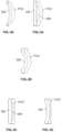
- FIG. 1is a front view of a collapsible prosthetic heart valve according to the prior art
- FIG. 2is a highly schematic transverse cross-sectional view of the prior art prosthetic heart valve implanted in a patient, taken along line 2 - 2 of FIG. 1 ;
- FIG. 3 Ais a schematic view of a stent according to an embodiment of the disclosure in a flattened condition with an inner cuff and an outer cuff;
- FIG. 3 Bis a highly schematic transverse cross-sectional view of a prosthetic heart valve including the stent and outer cuff of FIG. 3 A implanted in a patient;
- FIG. 3 Cis a highly schematic view of retrograde blood flowing into a portion of the outer cuff on the stent of FIG. 3 A ;
- FIG. 3 Dis a side view of a portion of the outer cuff on the stent of FIG. 3 A in an expanded condition
- FIG. 4 Ais a highly schematic longitudinal cross-sectional view of a stent according to another embodiment of the disclosure.
- FIG. 4 Bis a side view of a portion of an outer cuff on the stent of FIG. 4 A in an expanded condition
- FIG. 4 Cis a highly schematic view of retrograde blood flowing into a portion of the outer cuff on the stent of FIG. 4 A ;
- FIG. 4 Dis a side view of a portion of an outer cuff on the stent of FIG. 4 A in a collapsed condition
- FIG. 5 Ais a side view of a portion of an outer cuff on an alternate embodiment of a stent in an expanded condition
- FIG. 5 Bis a side view of a portion of the outer cuff on the stent of FIG. 5 A in a collapsed condition
- FIG. 5 Cis a side view of a portion of the outer cuff on an alternate embodiment of a stent in an expanded condition
- FIG. 5 Dis a side view of a portion of the outer cuff on the stent of FIG. 5 C in a collapsed condition
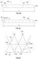
- FIG. 6 Ais a side view of an outer cuff with notches in a flattened condition according to another embodiment of the disclosure
- FIG. 6 Bis a side view of the outer cuff of FIG. 6 A after connecting portions of the outer cuff adjacent the notches;
- FIG. 6 Cis a highly schematic view of the outer cuff of FIG. 6 A coupled to the stent and/or inner cuff of FIG. 3 A ;
- FIG. 6 Dis a side view of an outer cuff with notches in a flattened condition having an alternate pattern to that shown in FIG. 6 A ;
- FIG. 6 Eis a side view of the outer cuff of FIG. 6 D after connection portions of the outer cuff adjacent the notches;
- FIG. 6 Fis a highly schematic view of the outer cuff of FIG. 6 D coupled to the stent and/or inner cuff of FIG. 3 A ;
- FIG. 7 Ais a side view of an outer cuff with a plurality openings in a flattened condition
- FIG. 7 Bis a highly schematic view of the outer cuff of FIG. 7 A coupled to the stent and/or inner cuff of FIG. 3 A .
- the term “inflow end,” when used in connection with a prosthetic heart valve,refers to the end of the heart valve through which blood enters when the valve is functioning as intended.
- the term “proximal”refers to the inflow end of a prosthetic heart valve or to elements of a prosthetic heart valve that are relatively close to the inflow end
- distalrefers to the outflow end of a prosthetic heart valve or to elements of a prosthetic heart valve that are relatively close to the outflow end.
- the term “outflow end,” when used in connection with a prosthetic heart valverefers to the end of the heart valve through which blood exits when the valve is functioning as intended.
- the terms “generally,” “substantially,” and “about”are intended to mean that slight deviations from absolute are included within the scope of the term so modified.
- Like numbersrefer to similar or identical elements throughout.
- the “lengthwise direction” or “axial direction”refer to a direction along a longitudinal axis passing through the center of the stent or heart valve.
- the “circumferential direction”refers to a direction extending along the circumference of the prosthetic heart valve in a direction orthogonal to the longitudinal axis.
- FIG. 1shows a collapsible stent-supported prosthetic heart valve 100 in an expanded condition according to the prior art.
- the prosthetic heart valve 100is designed to replace the function of a native aortic valve of a patient.
- the prosthetic heart valve 100includes a stent constructed as a frame 102 .
- the stent 102extends from an inflow or annulus end 130 to an outflow or aortic end 132 along a lengthwise or longitudinal axis L, and includes an annulus section 104 adjacent the inflow end 130 and an aortic section 142 adjacent the outflow end 132 .
- the annulus section 104has a relatively small cross-section in the expanded condition, while the aortic section 142 has a relatively large cross-section in the expanded condition.
- the annulus section 104may be in the form of a cylinder having a substantially constant diameter along its length.
- a transition section 141may taper outwardly from the annulus section 104 to the aortic section 142 .
- Each of the sections of the stent 102includes a plurality of cells 112 connected to one another in one or more annular rows around the stent 102 .
- the annulus section 104may have two annular rows of complete cells 112 and the aortic section 142 and the transition section 141 may each have one or more annular rows of complete or partial cells 112 .
- the cells 112 in the aortic section 142may be larger than the cells 112 in the annulus section 104 .
- the larger cells 112 in the aortic section 142may better enable the prosthetic valve 100 to be positioned without the structure of the stent 102 interfering with blood flow to the coronary arteries. At least partly due to the shape of cells 112 , the stent 102 elongates in the direction of axis L as cells 112 collapse when the stent 102 is transitioned from the expanded condition to the collapsed condition.
- the stent 102may include one or more retaining elements 118 at the outflow end 132 , the retaining elements 118 being sized and shaped to cooperate with retaining structures provided on a deployment device (not shown).
- the engagement of the retaining elements 118 with the retaining structures on the deployment devicemay help maintain the prosthetic heart valve 100 in assembled relationship with the deployment device, minimize longitudinal movement of the prosthetic heart valve relative to the deployment device during unsheathing or resheathing procedures, and help prevent rotation of the prosthetic heart valve relative to the deployment device as the deployment device is advanced to the target location and during deployment.
- One such deployment deviceis shown in U.S. Patent Publication No. 2012/0078352, the entire contents of which are hereby incorporated by reference herein.
- the stent 102may also include a plurality of commissure attachment features or points 116 for mounting the commissures of the valve assembly to the stent 102 .
- each commissure attachment feature 116may lay at the intersection of four cells 112 , two of the cells 112 being adjacent one another in the same annular row, and the other two cells 112 being in different annular rows and lying in end to end relationship.
- the commissure attachment features 116may be positioned entirely within the annulus section 104 or at the juncture of annulus section 104 and transition section 141 , and may include one or more eyelets which facilitate the suturing of the leaflet commissures to the stent.
- the stent 102may be formed as a unitary structure, for example, by laser cutting or etching a tube of a super elastic and/or shape memory metal alloy such as a nickel-titanium alloy of the type sold under the designation nitinol.
- a unitary structurecan also be referred to as a “non-woven” structure, in that it is not formed by weaving or winding one or more filaments.
- the prosthetic heart valve 100includes a valve assembly 140 positioned at least partially in the annulus section 104 .
- the valve assemblyincludes a cuff 106 and a plurality of leaflets 108 that collectively function as a one way valve by coapting with one another.
- FIG. 1illustrates a prosthetic heart valve for replacing a native aortic valve
- the prosthetic heart valveis shown with three leaflets 108 . Two leaflets join one another at each of three commissures.
- bloodflows from the inflow end 130 , past leaflets 108 , and toward the outflow end 132 . This occurs when the pressure in the left ventricle is greater than the pressure in the aorta, forcing the leaflets 108 to open.
- the valve assembly 140may be mounted to the stent 102 by suturing the commissures of the leaflets 108 to each of the three commissure attachment features 116 and suturing other portions of the leaflets 108 to the stent 102 and/or cuff 106 , or by other methods known in the art.
- each leaflet 108may define a leaflet belly B, indicated with broken lines in FIG. 1 .
- the leaflet belly Bis the portion of valve assembly 140 above which leaflets 108 are free to move radially inwardly to coapt with one another along their free edges.
- the cuff 106is shown in FIG. 1 as being disposed on the lumenal or inner surface of the annulus section 104 , the cuff 106 may be disposed on the ablumenal or outer surface of annulus section 104 , or may cover all or part of either or both of the lumenal and ablumenal surfaces of the annulus section 104 .
- the entirety of the valve assembly 140including the leaflet commissures, is positioned in the annulus section 104 of the stent 102 . When open, the leaflets may extend further into the transition section 141 or may be designed such that they remain substantially completely within the annulus section 104 .
- substantially the entirety of the valve assembly 140is positioned between the inflow end 130 of stent 102 and the commissure attachment features 116 , and none of the valve assembly is positioned between the commissure attachment features 116 and the outflow end 132 of the stent 102 .
- the embodiment of the prosthetic heart valve 100 described abovemay be used to replace a native heart valve, such as the aortic valve, a surgical heart valve, or a heart valve that has undergone a surgical procedure.
- the prosthetic heart valve 100may be delivered to the desired site (e.g., near a native aortic annulus) using any suitable delivery device.
- the prosthetic heart valve 100is disposed inside the delivery device in the collapsed condition.
- the delivery devicemay be introduced into a patient using any known procedures, such as a transfemoral, transapical, subclavian or transseptal approach. Once the delivery device has reached the target site, the user may deploy the prosthetic heart valve 100 .
- the prosthetic heart valve 100Upon deployment, the prosthetic heart valve 100 expands into secure engagement within the native aortic annulus. When the prosthetic heart valve 100 is properly positioned inside the heart, it works as a one-way valve, allowing blood to flow in one direction and preventing blood from flowing in the opposite direction.
- FIG. 2is a highly schematic transverse cross-sectional illustration of the prosthetic heart valve 100 having leaflets 108 disposed within the native valve annulus 250 , taken along line 2 - 2 shown in FIG. 1 .
- the substantially circular annulus section 104 of the stent 102is disposed within a non-circular native valve annulus 250 .
- gaps 200form between the heart valve 100 and the native valve annulus 250 . Blood flowing through these gaps and around the outside of the valve assembly 140 of the prosthetic heart valve 100 can result in PV leak or regurgitation and other inefficiencies which can reduce cardiac performance.
- Such improper fitmentmay be due to suboptimal native valve annulus geometry due, for example, to calcification of the native valve annulus 250 or due to unresected native leaflets.
- FIG. 3 Aillustrates a stent 302 of a prosthetic heart valve according to an aspect of the disclosure.
- Stent 302may be used in a prosthetic heart valve that is similar or identical to prosthetic heart valve 100 described above with certain exceptions.
- annulus section 304 of stent 302may include three rows of cells 312 instead of two rows, although stent 302 may alternatively include two rows of cells 312 in annulus section 304 .
- commissure attachment features 316 of stent 302are illustrated as open rectangles, the commissure attachment features 316 may take a form similar to commissure attachment features 116 , or any other suitable form including any number of rows or columns of eyelets and/or eyelets of different sizes and/or shapes positioned in any arrangement on the commissure attachment feature.
- a cuff 306 similar or identical to cuff 106may be positioned on the lumenal and/or ablumenal surface of stent 302 . Although cuff 106 is shown as scalloped at its inflow end, cuff 306 may have a straight inflow end rather than a scalloped one. In order to help eliminate PV leak, for example through the gaps 200 shown in FIG.
- outer cuff 350may have a substantially rectangular shape and may be wrapped around the circumference of stent 302 at its inflow end. Outer cuff 350 may be positioned anywhere along the height of stent 302 , so long as the proximal edge of the outer cuff is either at the proximal edge of inner cuff 306 or between the proximal and distal edges of the inner cuff, and the distal edge of the outer cuff is either at the distal edge of the inner cuff or between the proximal and distal edges of the inner cuff.
- outer cuff 350is positioned on stent 302 so as to overlap in the longitudinal direction of stent 302 with inner cuff 306 .
- Outer cuff 350may be a single piece of material including a proximal edge 352 , two side edges 354 , 356 , and a distal edge 358 .
- the proximal edge 352 of outer cuff 350is coupled to the stent 302 and/or to the inner cuff 306 along a proximal edge of the stent 302 and/or a proximal edge of the inner cuff 306 , for example by a continuous line of sutures (not shown), so that retrograde blood flow entering the space between the outer cuff 350 and the inner cuff 306 cannot pass in the retrograde direction beyond the combination of cuffs.
- the distal edge 358may be attached at spaced apart locations to the stent 302 and/or the inner cuff 306 .
- the distal edge 358 of outer cuff 350is sutured to stent 302 at attachment points S 1 which are located at the intersection of each cell 312 in the proximalmost row of cells with an adjacent cell 312 in that same row.
- attachment points S 1which are located at the intersection of each cell 312 in the proximalmost row of cells with an adjacent cell 312 in that same row.
- Retrograde blood flow around the ablumenal surface of stent 302may enter the pocket or space between outer cuff 350 and inner cuff 306 via the space between any two adjacent attachment points S 1 .
- outer cuff 350may tend to billow outwardly, helping to seal any of the gaps 200 between the prosthetic heart valve and the native annulus 250 .
- inner cuff 306may be located either on the lumenal or ablumenal surface of stent 302 , or on both surfaces. It should be understood that in FIG. 3 A , only part of the outline of inner cuff 306 is visible, as a bottom or proximal end of inner cuff 306 is positioned behind outer cuff 350 in the view of FIG. 3 A .
- outer cuff 350may comprise multiple pieces of material that in the aggregate form a similar shape and provide similar function to that described above for outer cuff 350 .
- outer cuff 350may be formed as a continuous tube without defining distinct side edges 354 , 356 .
- outer cuff 350has an axial height measured from proximal edge 352 to distal edge 358 that is approximately half the axial height of the cells 312 in the proximalmost row of stent 302 as measured along the major axes of the cells between two apices when the cells are in an expanded condition.
- outer cuff 350may be suitable, such as the full axial height of the cells 312 in the proximalmost row of cells, or more or less than the full axial height of such cells 312 .
- different heights of outer cuff 350may result in a change of the position of attachment points S 1 .
- the attachment points S 1could be positioned at the distalmost apex of such cells 312 .
- outer cuff 350is described above as separate from the inner cuff 306 , the outer cuff 350 may be integral with the inner cuff 306 , the combined cuff wrapping around the inflow end of stent 302 . With this configuration, the proximal edge 352 of outer cuff 350 does not need to be sutured to stent 302 , although it still may be preferable to provide such attachment.
- Both the inner cuff 306 and the outer cuff 350may be formed of the same or different materials, including any suitable biological material or polymer such as, for example, polytetrafluoroethylene (PTFE), ultra-high molecular weight polyethylene (UHMWPE), polyurethane, polyvinyl alcohol, polyester, silicone, or combinations thereof.
- PTFEpolytetrafluoroethylene
- UHMWPEultra-high molecular weight polyethylene
- polyurethanepolyvinyl alcohol
- polyesterpolyester
- siliconesilicone
- FIG. 3 Bwhen a prosthetic heart valve including stent 302 and outer cuff 350 is implanted into a native valve annulus 250 , retrograde blood flow may cause outer cuff 350 to billow radially outward and fill gaps 200 .
- outer cuff 350may billow radially outward and fill gaps 200 .
- that bloodmay not easily be able to migrate past the cell struts located between the inner and outer cuffs toward the proximal edges of the cuffs when certain conditions are present. This point is illustrated in FIG. 3 C .
- the bloodcan enter the space between outer cuff 350 and inner cuff 306 via the openings between attachment points S 1 , as described above. If a condition exists in which outer cuff 350 is taut when stent 302 is in the expanded condition, blood may not be able to pass across struts 312 c and 312 d into the space of adjacent cells (or half-cells), such as those directly under attachment points S 1 . As shown in FIG.
- outer cuff 350may be provided with an enhanced ability to billow outwardly to fill gaps 200 .
- FIG. 4 Ashows a longitudinal cross-sectional view of a stent 402 that may be identical to stent 302 , with certain exceptions described below.
- Stent 402may be used with an inner cuff and outer cuff similar or identical to inner cuff 306 and outer cuff 350 , respectively.
- stent 402may include two rows of cells 412 in an annulus section, with inner cuff 306 and outer cuff 350 coupled to stent 402 in a similar or identical manner to that described in connection with stent 302 .
- the annulus section 304 of stent 302may be substantially cylindrical when in the expanded condition, certain struts of stent 402 may be bowed radially inwardly.
- struts 412 c and/or struts 412 d of cells 412 in the proximalmost row of cells of stent 402may be bowed, arched, or otherwise curved radially inwardly so that, when stent 402 is in the expanded condition, a center portion of each of these curved struts 412 c , 412 d is positioned radially inwardly of proximal and distal portions of those curved struts.
- the curvature of struts 412 c and/or struts 412 dmay be such that the terminal ends of these curved struts are positioned a substantially equal distance in the radial direction from the longitudinal axis of stent 402 , and the center portions of these struts are positioned at a lesser distance in the radial direction from the longitudinal axis.
- the lumenal surface of struts 412 c and 412 dmay have a convex curvature along the entire length of the struts between their proximal and distal ends, with the ablumenal surface of those struts having a concave curvature along the entire length of the struts between their proximal and distal ends.
- the blood between outer cuff 350 and inner cuff 306may readily flow across struts 412 c and 412 d in the directions D 1 by way of the open space 490 between outer cuff 350 and the center portions of struts 412 c and 412 d , so that any portion of outer cuff 350 adjacent a gap 200 may be able to billow outwardly to fill that gap.
- each strut 412 c and 412 d in the proximalmost row of cellsis curved as described above, providing a similar curvature to some but less than all of these struts, such as only struts 412 c and not struts 412 d , or only struts 412 d and not struts 412 c , may provide a similar benefit.
- Struts 412 c and 412 dmay be set to the desired shape in a similar or identical fashion as the remainder of the stent 402 is shape-set, for example by heat-setting.
- the shape of struts 412 c and 412 dmay be set so that the curvature described above completely or substantially remains when stent 402 is the collapsed condition. This feature may result in a reduction in the forces encountered upon loading the prosthetic valve into a delivery device in the collapsed condition. For example, as shown in FIG. 4 D , portions of outer cuff 350 adjacent the curved portions of struts 412 c and 412 d may nest or otherwise sit along the curved struts 412 c and 412 d , which may reduce the overall bulkiness of the prosthetic heart valve in those areas.
- the struts 412 c and/or 412 dmay take other shapes upon stent 402 collapsing.
- struts 412 c and 412 dmay become substantially parallel to a longitudinal axis of the stent when in the collapsed condition in some embodiments.
- FIGS. 4 A-Dillustrate an embodiment of stent 402 in which the struts 412 c and 412 d in the cells 412 in the proximalmost row of cells are curved or bowed radially inwardly along substantially the entire length of those struts.
- FIGS. 5 A-Billustrate a strut 412 c ′ of a stent and the outer cuff 350 of a prosthetic heart valve that is identical in every way to the prosthetic heart valve including stent 402 and outer cuff 350 described above, except for the curvature of the struts corresponding to struts 412 c and 412 d .
- struts 412 c ′are bowed radially inwardly so that a center portion of each strut is positioned radially inwardly of proximal and distal portions of that strut when the stent is in the expanded condition
- the struts 412 c ′are not curved along substantially their entire length. Rather, proximal and distal portions of struts 412 c ′ may be positioned substantially within the same cylindrical surface of revolution about the longitudinal axis of the stent, which surface also includes the struts in other cells in the annulus section of the stent.
- the portion of struts 412 c ′ that is bowed radially inwardmay be isolated to a center portion of the struts, with the proximal and distal portions lacking such curvature.
- the lumenal surface of the center portion of strut 412 c ′may have a convex curvature in the length direction of that strut, while the ablumenal surface of the center portion of the strut has a convex curvature in the same length direction.
- the proximal and distal end portions of strut 412 c ′may each be substantially straight in the length direction of the strut, and may be collinear.
- each strut 412 c ′ and the outer cuff 350together define an open space 490 ′, generally similar to open space 490 , that may allow for blood positioned between outer cuff 350 and inner cuff 306 to migrate across struts 412 c ′, even if outer cuff 350 is taut.
- open space 490 ′generally similar to open space 490 , that may allow for blood positioned between outer cuff 350 and inner cuff 306 to migrate across struts 412 c ′, even if outer cuff 350 is taut.
- struts corresponding to struts 412 dmay have the same or similar shape and curvature as struts 412 c ′. Also, similar to the embodiment described in connection with FIGS.
- the curvature of struts 412 c ′may result in a reduction in the forces encountered upon loading the prosthetic valve into a delivery device in the collapsed condition, where portions of outer cuff 350 nest or otherwise sit along the curved portions of the struts.
- Other benefits that may be provided by the embodiment shown in FIGS. 5 A-Bmay include easier fabrication, the facilitation of proper resheathing of the valve during surgery if desired, and maintaining consistent outward radial force of the stent on the native anatomy.
- FIG. 5 Cillustrates a strut 412 c ′′ of a stent that is identical to stent 402 in every aspect other than the shape of the struts corresponding to struts 412 c and 412 d .
- Struts 412 c ′′(and the struts corresponding to struts 412 d of stent 402 ) may be formed so that their center portions' have a reduced thickness or diameter compared to their proximal and distal portions. This may be accomplished, for example, by laser cutting or grit blasting struts 412 c ′′ (and the struts corresponding to struts 412 d ) to have a reduced thickness. In order to create open spaces 490 ′′, the thickness of struts 412 c ′′ should be reduced so that the proximal and distal portions of the struts extend farther radially outward than center portions of the struts.
- the sides of the struts 412 c ′′ forming a portion of the lumenal surface of the stentshould have little or no curvature in the length direction of the struts, whereas the sides of the struts forming a portion of the ablumenal surface of the stent (toward the left in FIG. 5 C ) should be curved in the length direction of the struts.
- struts 412 c and 412 c ′have a concavely curved ablumenal surface and a convexly curved lumenal surface in the length direction of the struts
- struts 412 c ′′have a concavely curved ablumenal surface in the length direction of the struts, but a substantially straight lumenal surface in the length direction of the struts.
- a typical strut of stent 402has a thickness of between about 0.015 and about 0.018 inches
- the center portion of struts 412 c ′′may have a thickness that is reduced by between about 0.004 and about 0.005 inches compared to the other struts (and compared to the proximal and distal ends of struts 412 c ′′.
- outer cuff 350may at least partially nest or sit within the axially curved surfaces of struts 412 c ′′. It should be understood that although particular shapes, for example of inward curves, are illustrated in FIGS.
- any shape of struts 412 c and 412 d(or struts corresponding to struts 412 c and 412 d ) that provides space between the strut and an adjacent cuff, whether an inner or outer cuff, may be suitable to increase blood flow across that strut and between the cuffs.
- FIG. 6 Aillustrates an outer cuff 550 that may be used, instead of outer cuff 350 , with an inner cuff 306 and a stent similar or identical to stent 302 .
- Outer cuff 550generally has a straight inflow or proximal edge 552 , correspondingly angled side edges 554 and 556 , and a scalloped outflow or distal edge 558 , and may be formed from any of the materials noted above for forming the other cuffs described herein, either from a single piece of material, from more than one piece of material, or as a single tubular member (i.e., without side edges 554 and 556 ).
- Outer cuff 550may be wrapped around stent 302 with edges 554 and 556 sutured or otherwise attached to one another.
- the proximal edge 552 of outer cuff 550may be attached to the inflow end of stent 302 and/or to inner cuff 306 , for example by a continuous line of sutures, so that the outer cuff 550 is positioned at any height between the proximal and distal edges of the inner cuff 306 .
- cuffs hereinare shown with a straight distal edge, those cuffs may have a scalloped distal edge as shown in FIG. 6 A , or outer cuff 550 may have a substantially straight distal edge.
- the attachment points coupling outer cuff 550 to stent 302 and/or inner cuff 306are positioned at the peaks of distal edge 558 , with the troughs not being directly coupled to the stent or the inner cuff.
- the substantially straight proximal edge 552 of outer cuff 550may be interrupted by a plurality of spaced notches 553 .
- Each notch 553may be substantially triangular in shape with the base of the triangle (i.e., the base of the notch) positioned along proximal edge 552 .
- the proximal edge 552 of outer cuff 550has an end-to-end length L 1 such that, if outer cuff 550 is wrapped into a tube so that edges 554 and 556 mate, the circumference of the proximal edge will have a greater length than the circumference of the stent 302 at the position at which outer cuff 550 is intended to connect to the stent or inner cuff.
- the notches 553Prior to attachment to stent 302 , the notches 553 may be closed by coupling the portions of proximal edge 552 adjacent each notch 553 to one another, for example by sutures, adhesives, or any other suitable method, so that the proximal edge 552 is substantially continuous without interruption.
- the length L 2 of the proximal edge 552is reduced compared to the length L 1 .
- the reduction in the length of the proximal edge 552 upon closing the notches 553is substantially equal to the aggregate length of the open bases of the notches.
- the length of the open base of each notch 553may be selected depending on, for example, the number of cells in the stent 302 and the size of the prosthetic heart valve incorporating the stent and the outer cuff 550 .
- the base of each notch 553may be between about 0.04 inches and 0.06 inches long, preferably about 0.05 inches long.
- the resulting length L 2 of proximal edge 552is substantially equal to the circumference of the portion of stent 302 or the portion of inner cuff 306 to which the outer cuff 550 will be attached. Because the length of proximal edge 552 decreases upon coupling together the portions of the proximal edge adjacent each notch 553 , the material of outer cuff 550 may gather at the positions of the notches 553 to form puckered areas 555 , as shown in FIG. 6 B .
- the distal edge 558 of outer cuff 550may be attached to stent 302 and/or inner cuff 306 , for example on the ablumenal surface of the stent along the proximalmost row of cells 312 , at attachment points S 1 , similar to the attachment of outer cuff 350 to stent 302 and/or inner cuff 306 as described in connection with FIGS. 3 A-D .
- each peak of distal edge 558may be attached to stent 302 and/or inner cuff 306 at the locations at which two adjacent cells 312 in the proximalmost row of cells intersect one another, with the portions of the distal edge between attachment points S 1 remaining detached from both the stent and the inner cuff.
- the notches 553are preferably positioned so they are substantially aligned in the axial direction with the peaks of the distal edge 558 of outer cuff 550 .
- the puckered portions 555 of the outer cuffare positioned between strut 312 c of one cell and strut 312 d of a circumferentially adjacent cell in the proximalmost row of cells.
- the puckered portions 555 of outer cuff 550reduce the tautness of, or increase the slack in, outer cuff 550 at these positions, allowing for blood located between the outer cuff and inner cuff 306 to more easily migrate in those locations.
- retrograde blood flowing into the space between outer cuff 550 and inner cuff 306may more easily migrate across struts 312 c and 312 d due to the additional space provided by the puckered portions 555 of the outer cuff which, in turn, allows for the outer cuff to billow outwardly into gaps 200 more completely.
- the open bases of notches 553may be closed with a suture at attachment points S 2 prior to coupling the outer cuff 550 to the stent 302 and/or inner cuff 306 .
- the sutures at attachment points S 2may be separate from a substantially continuous suture line coupling the proximal edge 552 of outer cuff 550 to the stent 302 and/or inner cuff 306 .
- other methodsmay be used to couple the proximal edge 552 of outer cuff 550 to the stent 302 and/or inner cuff 306 .
- the open bases of notches 553are not closed in a step that is separate from attaching the proximal edge 552 of the outer cuff 550 to the stent 302 and/or inner cuff 306 .
- the proximal edge 552 of outer cuff 550may be attached to the stent 302 and/or inner cuff 306 by a single continuous suture line, without providing separate sutures to close the open bases of the notches 553 .
- a sutureis used to couple the proximal edge 552 of outer cuff 550 to the stent 302 and/or inner cuff 306 , and as the suture approaches a notch 553 , the user may gather portions of the proximal edge to close the open base of the notch 553 and continue the suturing so that an additional suture element is not needed to hold the notches 553 in the closed condition. It should be understood that once the portions of the proximal edge 552 of outer cuff 550 adjacent each notch 553 are coupled together, it may not be critical to ensure that the entire space of the notch 553 is completely sealed.
- gapsmay remain in outer cuff 550 where the notches 553 are positioned without significant leakage of blood through those gaps. Allowing some amount of gap to remain in notches 553 may even be beneficial. For example, leaving such gaps may provide openings for a user to eliminate air bubbles trapped between outer cuff 550 and inner cuff 306 prior to implanting the prosthetic valve into the patient.
- the outer cuffincludes nine peaks and nine troughs, with nine notches 553 axially aligned with corresponding peaks, and stent 302 includes nine cells 312 in the proximalmost row of cells.
- the outer cuff 550may include more or fewer notches 553 than shown, and the number of notches does not need to match the number of cells 312 in the row of cells positioned adjacent the outer cuff.
- outer cuff 550 of FIGS. 6 A-Bmay be used with the stent 402 of FIG. 4 A , rather than with stent 302 .
- outer cuff 550is used with stent 402 , the extra material of the outer cuff in the puckered portions 555 may nest with the bowed struts 412 c and 412 d of stent 402 , similar to outer cuff 350 shown in FIG. 4 D , to help reduce the forces encountered upon loading the prosthetic heart valve including outer cuff 550 into the delivery device in a collapsed condition.
- notches 553are shown as triangular in shape, other shapes may be suitable.
- rectangular or trapezoidal shapesmay be suitable for the notches 553 .
- triangular shapesmay help produce a substantially continuous proximal edge 552 as the bases of notches 553 are closed, while at the same time minimizing the size of any gaps that may be formed and through which blood may escape from between outer cuff 550 and inner cuff 306 .
- the size of the notchesmay also be varied to alter the characteristics of the resulting puckered portions 555 . For example, a smaller notch would result in a smaller puckered portion compared to a larger notch. A greater number of smaller notches could therefore result in many smaller puckered portions, while a smaller number of larger notches would result in a fewer larger puckered portions.
- outer cuff 550 ′is shown as outer cuff 550 ′ in FIGS. 6 D-F .
- Outer cuff 550 ′is similar or identical to outer cuff 550 in all respects other than the positioning of notches 553 ′, and the resulting position of puckered portions 555 ′. Whereas notches 553 of outer cuff 550 are illustrated as being in substantial axial alignment with the peaks of distal edge 558 , notches 553 ′ of outer cuff 550 ′ may be positioned in axial alignment with the valleys of the distal edge.
- puckered portions 555 ′are created, much the same as puckered portions 555 .
- puckered portions 555 ′are created in axial alignment with the valleys of the distal edge 558 of outer cuff 550 ′, as shown in FIG. 6 E .
- the puckered portions 555 ′are positioned between struts 312 c , 312 d of a cell 312 across which the free distal edge of outer cuff 550 ′ extends.
- puckered portions 555 ′are positioned between adjacent attachment points 51 of the distal edge 558 of cuff 550 ′ to the stent in a circumferential direction of the stent. It should be understood that the variations described with respect to outer cuff 550 , for example in terms of the size and number of notches 553 , may apply with equal force to outer cuff 550 ′, including in terms of the size and number of notches 553 ′.
- the solutions described abovemay help create greater billowing of the outer cuff 350 in the presence of retrograde blood flow, and hence greater sealing of the outer cuff against the native valve annulus 250 . Still other features may be provided in order to assist the outer cuff 350 from billowing outwardly, for example at a position adjacent to attachment points 51 where the distal edge 358 of the outer cuff is coupled to the stent 302 and/or inner cuff 306 .
- FIG. 7 Aillustrates an outer cuff 650 that may capture the retrograde blood flowing past attachment points 51 while enabling that blood flow to enter the space between outer cuff 650 and inner cuff 306 in the restricted space RS between struts 312 c and 312 d of adjacent cells 312 in the proximalmost row of cells.
- Outer cuff 650may be used instead of outer cuff 350 with an inner cuff 306 and a stent similar or identical to stent 302 .
- Outer cuff 650has a straight inflow or proximal edge 652 , correspondingly angled side edges 654 and 656 , and a scalloped outflow or distal edge 658 , and may be formed from any of the materials noted above for forming the other cuffs described herein, either from a single piece of material, from more than one piece of material, or as a single tubular member. Alternatively, outer cuff 650 may have a substantially straight distal edge 658 . Outer cuff 650 may be wrapped around stent 302 with edges 654 and 656 sutured or otherwise attached to one another.
- the proximal edge 652 of outer cuff 650may be attached to the inflow end of stent 302 and/or to inner cuff 306 , for example by a continuous line of sutures, so that the outer cuff 650 is positioned at any height between the proximal and distal edges of the inner cuff.
- the attachment points 51 coupling outer cuff 650 to stent 302 and/or inner cuff 306are positioned at the peaks of distal edge 658 (when distal edge 658 is scalloped), with the troughs not being directly coupled to stent 302 .
- Outer cuff 650may additionally include a plurality of apertures 653 .
- one aperture 653is provided for each peak in the distal edge 658 of outer cuff 650 .
- Each aperture 653may have a substantially triangular shape with a base of the triangle oriented substantially parallel to the proximal edge 652 of outer cuff 650 , and a vertex of the triangle positioned closer to the distal edge 658 of the outer cuff.
- the outer cuff 650may be formed without the apertures 653 , which later may be cut, stamped, or otherwise created in the outer cuff.
- each aperture 653will also be positioned just proximal of an attachment point S 1 .
- retrograde blood flow flowing past an attachment point S 1may be able to enter an aperture 653 and flow into the space between outer cuff 650 and inner cuff 306 in the restricted space RS between the strut 312 c of one cell and the strut 312 d of an adjacent cell.
- retrograde blood flow entering between the inner cuff 306 and the outer cuff 650 in the region between two adjacent attachment points S 1may cause the portion of the outer cuff between the struts 312 c and 312 d of a single cell 312 to billow away from the inner cuff and the stent 302 .
- retrograde blood flowing past an attachment point S 1 and entering restricted space RS through apertures 653may cause the portion of outer cuff 650 between the strut 312 c of one cell 312 and the strut 312 d of an adjacent cell to billow away from the inner cuff 306 and the stent 302 .
- outer cuff 650enables retrograde blood flowing past attachment points S 1 to be captured and the outer cuff to billow outwardly around the entire circumference of stent 302 to improve sealing upon the implantation of the prosthetic heart valve in the native valve annulus.
- apertures 653are shown as being substantially triangular, other shapes may be suitable. For example, a rectangular shape, a circular shape, a semi-circular shape, a crescent shape, a trapezoidal shape, or one or more slits in the outer cuff material in the circumferential direction may allow blood to enter the space between the outer and inner cuffs.
- the size of apertures 653is preferably large enough so that retrograde blood flow may enter the space between outer cuff 650 and inner cuff 306 , but not so large so that blood between outer cuff 650 and inner cuff 306 may readily escape through the apertures.
- the apex of the triangle closest to the distal edge 658may be spaced apart from the distal edge 658 between about 0.05 inches and about 0.15 inches, preferably between about 0.07 and about 0.1 inches.
- the base of the trianglemay be between about 0.1 inches and about 0.2 inches long, preferably about 0.15 inches long.
- these dimensionsare exemplary and may vary based on certain factors, such as the size of the prosthetic valve incorporating the outer cuff 650 .
- the apertures 653are preferably positioned in the distal half or distal third of outer cuff 650 in the axial direction so that the apertures are closer to distal edge 658 than to proximal edge 652 . This will enable the retrograde blood to flow into and occupy a greater portion of restricted spaces RS. It is preferable that some axial distance be maintained between the distal edge 658 at attachment points S 1 and the apertures 653 . If there is only a small amount of material axially separating an aperture 653 from an attachment point S 1 , there may be a risk that outer cuff 650 may tear between the aperture and the corresponding attachment point.
- the triangular shapes illustratedmay help maximize the strength of the remaining material between an aperture 653 and the distal edge 658 of the outer cuff 650 , while also maximizing the size of the aperture, particularly along the proximal base of the triangular shape, through which retrograde blood flow may pass.
- the apertures 653are illustrated with a triangular shape, it should be understood that one, two, or three of the vertices of the triangle shape may be rounded to eliminate a sharp angle at the corresponding vertex.
- one or more vertices of each aperture 653may be triangular with a rounded vertex having a radius of curvature of between about 0.01 inches and about 0.03 inches, preferably about 0.02 inches.
- Such a rounded vertexmay reduce stress concentrations compared to a vertex having a sharp angle, which may in particular reduce the likelihood of the outer cuff 650 adjacent a vertex of a triangular aperture 653 tearing, including in particular the vertex positioned closest to the distal edge 658 of outer cuff 650 .
- the apertures 653 in outer cuff 650may be combined with the notches 553 in outer cuff 550 , and that outer cuff 650 may also be used with stent 402 instead of stent 302 .
- FIGS. 4 A-D and 5 A-Beach show struts being bowed inwardly to create space between an outer cuff and the curved portions of the struts, similar results may be achieved be providing the opposite curvatures in the struts, to create space between an inner cuff and the curved portions of the struts.
- FIGS. 4 A-D and 5 A-Beach show struts being bowed inwardly to create space between an outer cuff and the curved portions of the struts, similar results may be achieved be providing the opposite curvatures in the struts, to create space between an inner cuff and the curved portions of the struts.
- 5 C-Dillustrate reducing the thickness of struts on an ablumenal surface of the struts to create space between the outer cuff and the reduced thickness portions of the struts
- the thickness of the strutsmay be reduced on a lumenal surface of the struts to create space between the inner cuff and the reduced thickness portions of the struts.
- Forming the struts with the curvature and/or reduced thickness shown in FIGS. 4 A-D and 5 A-Dmay be preferable to such alternative embodiments, however, as the embodiments of FIGS. 4 A-D and 5 A-D may provide for better anchoring and increased loading forces.
- a prosthetic heart valve for replacing a native valvecomprises:
- a stentextending in an axial direction between an inflow end and an outflow end and having circumferential rows of cells formed by cell struts, the stent having a collapsed condition and an expanded condition;
- valve assemblydisposed within the stent
- a second cuffhaving a proximal edge facing toward the inflow end of the stent and a distal edge facing toward the outflow end of the stent, the second cuff being annularly disposed about one of the circumferential rows of cells and positioned radially outward of the first cuff and the stent;
- an ablumenal surface of selected cell struts forming the one circumferential row of cellshas a concave curvature in a length direction of the selected cell struts when the stent is in the expanded condition;
- each of the selected cell strutshas end portions and a center portion between the end portions, with the stent in the expanded condition a radial distance between the ablumenal surface of the center portion and the second cuff being greater than a radial distance between the ablumenal surface of each end portion and the second cuff;
- a lumenal surface of the selected cell strutshas a convex curvature in the length direction of the selected cell struts when the stent is in the expanded condition;
- each of the selected cell strutshas a substantially constant strut thickness in a radial direction of the stent
- a lumenal surface of the selected cell strutsis substantially straight in the length direction of the selected cell struts when the stent is in the expanded condition;
- each of the selected cell strutshas end portions and a center portion between the end portions, the end portions and the center portion each having a strut thickness in a radial direction of the stent, the strut thickness of the center portion being less than the strut thicknesses of the end portions;
- the concave curvatureextends along an entire length of the selected cell struts
- the concave curvatureextends along less than an entire length of the selected cell struts.
- a prosthetic heart valve for replacing a native valvecomprises:
- a stentextending in an axial direction between an inflow end and an outflow end, the stent having a collapsed condition and an expanded condition;
- valve assemblydisposed within the stent
- a second cuffhaving a proximal edge facing toward the inflow end of the stent and a distal edge facing toward the outflow end of the stent, the second cuff being annularly disposed about the stent and positioned radially outward of the first cuff and the stent, the second cuff including a plurality of notches at spaced apart locations along the proximal edge, each of the notches defining a void in the proximal edge of the second cuff, the second cuff having an initial configuration in which the voids render the proximal edge of the second cuff discontinuous, and a gathered configuration in which the voids are closed so that the proximal edge of the second cuff is substantially continuous, the proximal edge of the second cuff in the gathered configuration having a length that is less than the length of the proximal edge of the second cuff in the initial configuration, the second cuff being coupled to at least one of the stent
- the second cuffincludes a plurality of puckered portions, each of the puckered portions being aligned in the axial direction with one of the notches and extending farther radially outwardly from the stent than portions of the second cuff positioned circumferentially between adjacent ones of the notches;
- each of the puckered portionsbeing positioned between a pair of adjacent attachment points in a circumferential direction of the stent;
- the stentincludes a plurality of circumferential rows of cells, the second cuff being in radial alignment with a proximalmost one of the circumferential rows of cells;
- each of the puckered portionsis positioned circumferentially between a pair of adjacent cells in the proximalmost row of cells;
- each of the notcheshas a triangular shape in the initial configuration of the second cuff.
- portions of the proximal edge of the second cuff adjacent each of the notchesare coupled to one another in the gathered configuration of the second cuff.
- a prosthetic heart valve for replacing a native valvecomprises
- a stentextending in an axial direction from an inflow end to an outflow end, the stent having a collapsed condition and an expanded condition;
- valve assemblydisposed within the stent
- a second cuffhaving a proximal edge facing toward the inflow end of the stent and a distal edge facing toward the outflow end of the stent, the second cuff being annularly disposed about the stent and positioned radially outward of the first cuff and the stent, the second cuff including a plurality of apertures; and/or
- each aperture in the second cuffbeing aligned in the axial direction with a respective one of the plurality of attachment points;
- each of the apertureshas a triangular shape
- each of the aperturesincludes a base oriented substantially parallel to the proximal edge of the second cuff and a vertex positioned closer to the distal edge of the second cuff than to the proximal edge of the second cuff;
- the stentincludes a plurality of circumferential rows of cells, the second cuff being in radial alignment with a proximalmost one of the circumferential rows of cells, and each of the apertures in the second cuff is positioned circumferentially between a pair of adjacent cells in the proximalmost row of cells.
Landscapes
- Health & Medical Sciences (AREA)
- Cardiology (AREA)
- Engineering & Computer Science (AREA)
- Biomedical Technology (AREA)
- Heart & Thoracic Surgery (AREA)
- Transplantation (AREA)
- Oral & Maxillofacial Surgery (AREA)
- Vascular Medicine (AREA)
- Life Sciences & Earth Sciences (AREA)
- Animal Behavior & Ethology (AREA)
- General Health & Medical Sciences (AREA)
- Public Health (AREA)
- Veterinary Medicine (AREA)
- Prostheses (AREA)
Abstract
Description
Claims (11)
Priority Applications (1)
| Application Number | Priority Date | Filing Date | Title |
|---|---|---|---|
| US16/551,958US11571296B2 (en) | 2016-09-15 | 2019-08-27 | Prosthetic heart valve with paravalvular leak mitigation features |
Applications Claiming Priority (3)
| Application Number | Priority Date | Filing Date | Title |
|---|---|---|---|
| US201662394837P | 2016-09-15 | 2016-09-15 | |
| US15/702,941US10456249B2 (en) | 2016-09-15 | 2017-09-13 | Prosthetic heart valve with paravalvular leak mitigation features |
| US16/551,958US11571296B2 (en) | 2016-09-15 | 2019-08-27 | Prosthetic heart valve with paravalvular leak mitigation features |
Related Parent Applications (1)
| Application Number | Title | Priority Date | Filing Date |
|---|---|---|---|
| US15/702,941ContinuationUS10456249B2 (en) | 2016-09-15 | 2017-09-13 | Prosthetic heart valve with paravalvular leak mitigation features |
Publications (2)
| Publication Number | Publication Date |
|---|---|
| US20190380832A1 US20190380832A1 (en) | 2019-12-19 |
| US11571296B2true US11571296B2 (en) | 2023-02-07 |
Family
ID=59955682
Family Applications (2)
| Application Number | Title | Priority Date | Filing Date |
|---|---|---|---|
| US15/702,941Active2037-09-14US10456249B2 (en) | 2016-09-15 | 2017-09-13 | Prosthetic heart valve with paravalvular leak mitigation features |
| US16/551,958ActiveUS11571296B2 (en) | 2016-09-15 | 2019-08-27 | Prosthetic heart valve with paravalvular leak mitigation features |
Family Applications Before (1)
| Application Number | Title | Priority Date | Filing Date |
|---|---|---|---|
| US15/702,941Active2037-09-14US10456249B2 (en) | 2016-09-15 | 2017-09-13 | Prosthetic heart valve with paravalvular leak mitigation features |
Country Status (3)
| Country | Link |
|---|---|
| US (2) | US10456249B2 (en) |
| EP (1) | EP3512466B1 (en) |
| WO (1) | WO2018052927A1 (en) |
Cited By (1)
| Publication number | Priority date | Publication date | Assignee | Title |
|---|---|---|---|---|
| US20200289262A1 (en)* | 2013-02-01 | 2020-09-17 | Medtronic CV Luxembourg S.a.r.l. | Anti-paravalvular leakage component for a transcatheter valve prosthesis |
Families Citing this family (22)
| Publication number | Priority date | Publication date | Assignee | Title |
|---|---|---|---|---|
| US8579964B2 (en) | 2010-05-05 | 2013-11-12 | Neovasc Inc. | Transcatheter mitral valve prosthesis |
| US9554897B2 (en) | 2011-04-28 | 2017-01-31 | Neovasc Tiara Inc. | Methods and apparatus for engaging a valve prosthesis with tissue |
| US9308087B2 (en) | 2011-04-28 | 2016-04-12 | Neovasc Tiara Inc. | Sequentially deployed transcatheter mitral valve prosthesis |
| US9345573B2 (en) | 2012-05-30 | 2016-05-24 | Neovasc Tiara Inc. | Methods and apparatus for loading a prosthesis onto a delivery system |
| US9572665B2 (en) | 2013-04-04 | 2017-02-21 | Neovasc Tiara Inc. | Methods and apparatus for delivering a prosthetic valve to a beating heart |
| WO2015126711A1 (en)* | 2014-02-18 | 2015-08-27 | St. Jude Medical, Cardiology Division, Inc. | Bowed runners and corresponding valve assemblies for paravalvular leak protection |
| CA3007660A1 (en) | 2015-12-15 | 2017-06-22 | Neovasc Tiara Inc. | Transseptal delivery system |
| US10433952B2 (en) | 2016-01-29 | 2019-10-08 | Neovasc Tiara Inc. | Prosthetic valve for avoiding obstruction of outflow |
| US10548722B2 (en)* | 2016-08-26 | 2020-02-04 | St. Jude Medical, Cardiology Division, Inc. | Prosthetic heart valve with paravalvular leak mitigation features |
| CA3042588A1 (en) | 2016-11-21 | 2018-05-24 | Neovasc Tiara Inc. | Methods and systems for rapid retraction of a transcatheter heart valve delivery system |
| CA3073834A1 (en) | 2017-08-25 | 2019-02-28 | Neovasc Tiara Inc. | Sequentially deployed transcatheter mitral valve prosthesis |
| US11813413B2 (en) | 2018-03-27 | 2023-11-14 | St. Jude Medical, Cardiology Division, Inc. | Radiopaque outer cuff for transcatheter valve |
| CN113271890B (en) | 2018-11-08 | 2024-08-30 | 内奥瓦斯克迪亚拉公司 | Ventricular deployment of transcatheter mitral valve prosthesis |
| CA3132873A1 (en) | 2019-03-08 | 2020-09-17 | Neovasc Tiara Inc. | Retrievable prosthesis delivery system |
| CA3135753C (en) | 2019-04-01 | 2023-10-24 | Neovasc Tiara Inc. | Controllably deployable prosthetic valve |
| US11491006B2 (en) | 2019-04-10 | 2022-11-08 | Neovasc Tiara Inc. | Prosthetic valve with natural blood flow |
| US11779742B2 (en) | 2019-05-20 | 2023-10-10 | Neovasc Tiara Inc. | Introducer with hemostasis mechanism |
| JP7520897B2 (en) | 2019-06-20 | 2024-07-23 | ニオバスク ティアラ インコーポレイテッド | Thin prosthetic mitral valve |
| CN112089508B (en)* | 2020-08-28 | 2022-11-18 | 江苏大学 | Anti-migration aortic valve stent |
| EP4525788A1 (en)* | 2022-05-16 | 2025-03-26 | Edwards Lifesciences Corporation | Outer skirt for an expandable prosthetic heart valve |
| WO2024067809A1 (en)* | 2022-09-30 | 2024-04-04 | 元心科技(深圳)有限公司 | Artificial heart valve |
| US20240423788A1 (en)* | 2023-06-23 | 2024-12-26 | St. Jude Medical, Cardiology Division, Inc. | Self-Closing Outer Cuff Using Valve Foreshortening |
Citations (217)
| Publication number | Priority date | Publication date | Assignee | Title |
|---|---|---|---|---|
| US3657744A (en) | 1970-05-08 | 1972-04-25 | Univ Minnesota | Method for fixing prosthetic implants in a living body |
| US4275469A (en) | 1979-12-13 | 1981-06-30 | Shelhigh Inc. | Prosthetic heart valve |
| US4491986A (en) | 1976-05-12 | 1985-01-08 | Shlomo Gabbay | Heart valve |
| US4759758A (en) | 1984-12-07 | 1988-07-26 | Shlomo Gabbay | Prosthetic heart valve |
| US4878906A (en) | 1986-03-25 | 1989-11-07 | Servetus Partnership | Endoprosthesis for repairing a damaged vessel |
| US4922905A (en) | 1985-11-30 | 1990-05-08 | Strecker Ernst P | Dilatation catheter |
| US4994077A (en) | 1989-04-21 | 1991-02-19 | Dobben Richard L | Artificial heart valve for implantation in a blood vessel |
| US5411552A (en) | 1990-05-18 | 1995-05-02 | Andersen; Henning R. | Valve prothesis for implantation in the body and a catheter for implanting such valve prothesis |
| US5415664A (en) | 1994-03-30 | 1995-05-16 | Corvita Corporation | Method and apparatus for introducing a stent or a stent-graft |
| US5480423A (en) | 1993-05-20 | 1996-01-02 | Boston Scientific Corporation | Prosthesis delivery |
| US5591197A (en) | 1995-03-14 | 1997-01-07 | Advanced Cardiovascular Systems, Inc. | Expandable stent forming projecting barbs and method for deploying |
| US5843167A (en) | 1993-04-22 | 1998-12-01 | C. R. Bard, Inc. | Method and apparatus for recapture of hooked endoprosthesis |
| US5855601A (en) | 1996-06-21 | 1999-01-05 | The Trustees Of Columbia University In The City Of New York | Artificial heart valve and method and device for implanting the same |
| US5857216A (en)* | 1996-11-15 | 1999-01-12 | Gold; Danny | Pre-curved gloves and mitts construction and methods of construction |
| US5935163A (en) | 1998-03-31 | 1999-08-10 | Shelhigh, Inc. | Natural tissue heart valve prosthesis |
| US5961549A (en) | 1997-04-03 | 1999-10-05 | Baxter International Inc. | Multi-leaflet bioprosthetic heart valve |
| US6045576A (en) | 1997-09-16 | 2000-04-04 | Baxter International Inc. | Sewing ring having increased annular coaptation |
| US6077297A (en) | 1993-11-04 | 2000-06-20 | C. R. Bard, Inc. | Non-migrating vascular prosthesis and minimally invasive placement system therefor |
| US6083257A (en) | 1995-11-01 | 2000-07-04 | Biocompatibles Limited | Braided stent |
| US6090140A (en) | 1999-02-17 | 2000-07-18 | Shelhigh, Inc. | Extra-anatomic heart valve apparatus |
| US6214036B1 (en) | 1998-11-09 | 2001-04-10 | Cordis Corporation | Stent which is easily recaptured and repositioned within the body |
| US6264691B1 (en) | 1999-04-23 | 2001-07-24 | Shlomo Gabbay | Apparatus and method for supporting a heart valve |
| US20020036220A1 (en) | 2000-09-26 | 2002-03-28 | Shlomo Gabbay | Curved implantable sheath and method of making same |
| US6368348B1 (en) | 2000-05-15 | 2002-04-09 | Shlomo Gabbay | Annuloplasty prosthesis for supporting an annulus of a heart valve |
| US6419695B1 (en) | 2000-05-22 | 2002-07-16 | Shlomo Gabbay | Cardiac prosthesis for helping improve operation of a heart valve |
| US6458153B1 (en) | 1999-12-31 | 2002-10-01 | Abps Venture One, Ltd. | Endoluminal cardiac and venous valve prostheses and methods of manufacture and delivery thereof |
| US6468660B2 (en) | 2000-12-29 | 2002-10-22 | St. Jude Medical, Inc. | Biocompatible adhesives |
| US6488702B1 (en) | 1997-01-24 | 2002-12-03 | Jomed Gmbh | Bistable spring construction for a stent and other medical apparatus |
| US20030023303A1 (en) | 1999-11-19 | 2003-01-30 | Palmaz Julio C. | Valvular prostheses having metal or pseudometallic construction and methods of manufacture |
| US6517576B2 (en) | 2000-12-11 | 2003-02-11 | Shlomo Gabbay | Implantable patch prosthesis having one or more cusps for improved competency |
| US20030050694A1 (en) | 2001-09-13 | 2003-03-13 | Jibin Yang | Methods and apparatuses for deploying minimally-invasive heart valves |
| US6533810B2 (en) | 1995-11-27 | 2003-03-18 | Schneider (Europe) Ag | Conical stent |
| US6582464B2 (en) | 2000-05-03 | 2003-06-24 | Shlomo Gabbay | Biomechanical heart valve prosthesis and method for making same |
| US20030130726A1 (en) | 1999-09-10 | 2003-07-10 | Thorpe Patricia E. | Combination valve and stent for treating vascular reflux |
| US6623518B2 (en) | 2001-02-26 | 2003-09-23 | Ev3 Peripheral, Inc. | Implant delivery system with interlock |
| US6685625B2 (en) | 2000-09-26 | 2004-02-03 | Shlomo Gabbay | Curved implantable sheath and method of making same |
| US20040049262A1 (en) | 2000-01-31 | 2004-03-11 | Obermiller Joseph F. | Stent valves and uses of same |
| US6716244B2 (en) | 2000-12-20 | 2004-04-06 | Carbomedics, Inc. | Sewing cuff assembly for heart valves |
| US6719789B2 (en) | 1993-11-01 | 2004-04-13 | 3F Therapeutics, Inc. | Replacement heart valve |
| US6730118B2 (en) | 2001-10-11 | 2004-05-04 | Percutaneous Valve Technologies, Inc. | Implantable prosthetic valve |
| US20040093075A1 (en) | 2000-12-15 | 2004-05-13 | Titus Kuehne | Stent with valve and method of use thereof |
| US20040111111A1 (en) | 2002-12-10 | 2004-06-10 | Scimed Life Systems, Inc. | Intravascular filter membrane with shape memory |
| US6783556B1 (en) | 2000-09-26 | 2004-08-31 | Shlomo Gabbay | System and method for making a calotte-shaped implantable sheath |
| US6790230B2 (en) | 2001-04-30 | 2004-09-14 | Universitatsklinikum Freiburg | Vascular implant |
| US20040210304A1 (en) | 1999-11-17 | 2004-10-21 | Corevalve, S.A. | Prosthetic valve for transluminal delivery |
| US6814746B2 (en) | 2002-11-01 | 2004-11-09 | Ev3 Peripheral, Inc. | Implant delivery system with marker interlock |
| US6830584B1 (en) | 1999-11-17 | 2004-12-14 | Jacques Seguin | Device for replacing a cardiac valve by percutaneous route |
| US20040260389A1 (en) | 2003-04-24 | 2004-12-23 | Cook Incorporated | Artificial valve prosthesis with improved flow dynamics |
| US6869444B2 (en) | 2000-05-22 | 2005-03-22 | Shlomo Gabbay | Low invasive implantable cardiac prosthesis and method for helping improve operation of a heart valve |
| US20050096726A1 (en) | 2000-05-30 | 2005-05-05 | Jacques Sequin | Noncylindrical stent deployment system for treating vascular bifurcations |
| US6908481B2 (en) | 1996-12-31 | 2005-06-21 | Edwards Lifesciences Pvt, Inc. | Value prosthesis for implantation in body channels |
| US20050137682A1 (en) | 2003-12-22 | 2005-06-23 | Henri Justino | Stent mounted valve |
| US20050137695A1 (en) | 2003-12-23 | 2005-06-23 | Sadra Medical | Replacement valve and anchor |
| US20050137697A1 (en) | 2003-12-23 | 2005-06-23 | Amr Salahieh | Leaflet engagement elements and methods for use thereof |
| US20050203605A1 (en) | 2004-03-15 | 2005-09-15 | Medtronic Vascular, Inc. | Radially crush-resistant stent |
| US6951573B1 (en) | 2001-12-22 | 2005-10-04 | Dilling Emery W | Prosthetic aortic valve |
| US20050240200A1 (en) | 2004-04-23 | 2005-10-27 | Bjarne Bergheim | Method and system for cardiac valve delivery |
| US20050256566A1 (en) | 2004-05-03 | 2005-11-17 | Shlomo Gabbay | Apparatus and method for improving ventricular function |
| US20060008497A1 (en) | 2004-07-09 | 2006-01-12 | Shlomo Gabbay | Implantable apparatus having improved biocompatibility and process of making the same |
| US7018406B2 (en) | 1999-11-17 | 2006-03-28 | Corevalve Sa | Prosthetic valve for transluminal delivery |
| US20060074484A1 (en) | 2004-10-02 | 2006-04-06 | Huber Christoph H | Methods and devices for repair or replacement of heart valves or adjacent tissue without the need for full cardiopulmonary support |
| US7025780B2 (en) | 2000-09-12 | 2006-04-11 | Shlomo Gabbay | Valvular prosthesis |
| US20060122692A1 (en) | 2004-05-10 | 2006-06-08 | Ran Gilad | Stent valve and method of using same |
| US20060149360A1 (en) | 2003-07-08 | 2006-07-06 | Ventor Technologies Ltd. | Fluid flow prosthetic device |
| US20060161249A1 (en) | 2004-11-22 | 2006-07-20 | Fidel Realyvasquez | Ring-shaped valve prosthesis attachment device |
| US20060173532A1 (en) | 2004-12-20 | 2006-08-03 | Jacob Flagle | Intraluminal support frame and medical devices including the support frame |
| US20060178740A1 (en) | 2005-02-10 | 2006-08-10 | Sorin Biomedica Cardio S.R.L. | Cardiac-valve prosthesis |
| US20060195180A1 (en) | 2005-02-25 | 2006-08-31 | Arash Kheradvar | Implantable small percutaneous valve and methods of delivery |
| US20060206202A1 (en) | 2004-11-19 | 2006-09-14 | Philippe Bonhoeffer | Apparatus for treatment of cardiac valves and method of its manufacture |
| US20060241745A1 (en) | 2005-04-21 | 2006-10-26 | Solem Jan O | Blood flow controlling apparatus |
| US20060241744A1 (en) | 2003-03-20 | 2006-10-26 | Aortech International Plc | Valve |
| US20060259136A1 (en) | 2005-05-13 | 2006-11-16 | Corevalve Sa | Heart valve prosthesis and methods of manufacture and use |
| US20060259137A1 (en) | 2003-10-06 | 2006-11-16 | Jason Artof | Minimally invasive valve replacement system |
| US20060259120A1 (en) | 2005-05-12 | 2006-11-16 | Ev3, Inc. | Implant delivery system with interlocked RX port orientation |
| US7137184B2 (en) | 2002-09-20 | 2006-11-21 | Edwards Lifesciences Corporation | Continuous heart valve support frame and method of manufacture |
| US20060276813A1 (en) | 2005-05-20 | 2006-12-07 | The Cleveland Clinic Foundation | Apparatus and methods for repairing the function of a diseased valve and method for making same |
| US20060276874A1 (en) | 2005-05-27 | 2006-12-07 | Heart Leaflet Technologies, Inc. | Intravascular cuff |
| US7160322B2 (en) | 2003-08-13 | 2007-01-09 | Shlomo Gabbay | Implantable cardiac prosthesis for mitigating prolapse of a heart valve |
| US20070010876A1 (en) | 2003-12-23 | 2007-01-11 | Amr Salahieh | Externally Expandable Heart Valve Anchor and Method |
| US20070027534A1 (en) | 2005-07-27 | 2007-02-01 | Bjarne Bergheim | Methods and systems for cardiac valve delivery |
| US20070043435A1 (en) | 1999-11-17 | 2007-02-22 | Jacques Seguin | Non-cylindrical prosthetic valve system for transluminal delivery |
| US20070055358A1 (en) | 2005-08-22 | 2007-03-08 | Krolik Jeffrey A | Axially compressible flared stents and apparatus and methods for delivering them |
| US20070067029A1 (en) | 2005-09-16 | 2007-03-22 | Shlomo Gabbay | Support apparatus to facilitate implantation of cardiac prosthesis |
| US20070093890A1 (en) | 2005-10-26 | 2007-04-26 | Eliasen Kenneth A | Heart valve implant |
| US20070100435A1 (en) | 2003-04-24 | 2007-05-03 | Cook Incorporated | Artificial prostheses with preferred geometries |
| US20070118210A1 (en) | 2005-11-18 | 2007-05-24 | Leonard Pinchuk | Trileaflet Heart Valve |
| US7247167B2 (en) | 2004-02-19 | 2007-07-24 | Shlomo Gabbay | Low profile heart valve prosthesis |
| US7267686B2 (en) | 1999-10-21 | 2007-09-11 | Boston Scientific Scimed, Inc | Implantable prosthetic valve |
| US20070213813A1 (en) | 2005-12-22 | 2007-09-13 | Symetis Sa | Stent-valves for valve replacement and associated methods and systems for surgery |
| US7276078B2 (en) | 2004-06-30 | 2007-10-02 | Edwards Lifesciences Pvt | Paravalvular leak detection, sealing, and prevention |
| US20070233228A1 (en) | 2006-03-28 | 2007-10-04 | Medtronic, Inc. | Prosthetic cardiac valve formed from pericardium material and methods of making same |
| US20070244552A1 (en) | 2003-12-23 | 2007-10-18 | Amr Salahieh | Assessing the location and performance of replacement heart valves |
| US20070244545A1 (en) | 2006-04-14 | 2007-10-18 | Medtronic Vascular, Inc. | Prosthetic Conduit With Radiopaque Symmetry Indicators |
| US20070288087A1 (en) | 2006-05-30 | 2007-12-13 | Cook Incorporated | Artificial valve prosthesis |
| US7311730B2 (en) | 2004-02-13 | 2007-12-25 | Shlomo Gabbay | Support apparatus and heart valve prosthesis for sutureless implantation |
| US7320704B2 (en) | 2004-05-05 | 2008-01-22 | Direct Flow Medical, Inc. | Nonstented temporary valve for cardiovascular therapy |
| US20080021552A1 (en) | 2001-10-09 | 2008-01-24 | Shlomo Gabbay | Apparatus To Facilitate Implantation |
| US20080039934A1 (en) | 2004-09-07 | 2008-02-14 | Laboratoires Perouse | Interchangeable Prosthetic Valve |
| US20080071369A1 (en) | 2006-09-19 | 2008-03-20 | Yosi Tuval | Valve fixation member having engagement arms |
| US20080082164A1 (en) | 2006-10-02 | 2008-04-03 | Friedman Robert S | Sutureless heart valve attachment |
| US20080097595A1 (en) | 2006-08-22 | 2008-04-24 | Shlomo Gabbay | Intraventricular cardiac prosthesis |
| US20080114452A1 (en) | 2007-11-14 | 2008-05-15 | Shlomo Gabbay | Prosthesis exhibiting post-implantation size change |
| US7374573B2 (en) | 2004-05-03 | 2008-05-20 | Shlomo Gabbay | System and method for improving ventricular function |
| US7381219B2 (en) | 2003-12-23 | 2008-06-03 | Sadra Medical, Inc. | Low profile heart valve and delivery system |
| US7381218B2 (en) | 2000-04-06 | 2008-06-03 | Edwards Lifesciences Corporation | System and method for implanting a two-part prosthetic heart valve |
| US20080140189A1 (en) | 2006-12-06 | 2008-06-12 | Corevalve, Inc. | System and method for transapical delivery of an annulus anchored self-expanding valve |
| US20080147183A1 (en) | 2006-12-14 | 2008-06-19 | Mikolaj Styrc | Endovalve |
| US20080154355A1 (en) | 2006-12-22 | 2008-06-26 | Netanel Benichou | Implantable prosthetic valve assembly and method of making the same |
| US20080243245A1 (en) | 2004-03-11 | 2008-10-02 | Percutaneous Cardiovascular Solutions Pty Limited | Percutaneous Heart Valve Prosthesis |
| US20080255662A1 (en) | 2004-03-03 | 2008-10-16 | Sorin Biomedica Cardio S.R.L. | Minimally-invasive cardiac-valve prosthesis |
| US20080262602A1 (en) | 1998-09-10 | 2008-10-23 | Jenavalve Technology, Inc. | Methods and conduits for flowing blood from a heart chamber to a blood vessel |
| US20080269879A1 (en) | 2005-07-27 | 2008-10-30 | Rahul Dilip Sathe | Implantable Prosthetic Vascular Valve |
| US7452371B2 (en) | 1999-06-02 | 2008-11-18 | Cook Incorporated | Implantable vascular device |
| US7510572B2 (en) | 2000-09-12 | 2009-03-31 | Shlomo Gabbay | Implantation system for delivery of a heart valve prosthesis |
| US20090099653A1 (en) | 2007-10-12 | 2009-04-16 | Sorin Biomedica Cardio S.R.L. | Expandable valve prosthesis with sealing mechanism |
| US7524331B2 (en) | 2006-04-06 | 2009-04-28 | Medtronic Vascular, Inc. | Catheter delivered valve having a barrier to provide an enhanced seal |
| US20090112309A1 (en) | 2005-07-21 | 2009-04-30 | The Florida International University Board Of Trustees | Collapsible Heart Valve with Polymer Leaflets |
| US20090138079A1 (en) | 2007-10-10 | 2009-05-28 | Vector Technologies Ltd. | Prosthetic heart valve for transfemoral delivery |
| US20090234443A1 (en) | 2005-01-20 | 2009-09-17 | Ottma Ruediger | Catheter for the Transvascular Implantation of Prosthetic Heart Valves |
| US20090276027A1 (en) | 2008-05-01 | 2009-11-05 | Medtronic Vasscular, Inc. | Stent Graft Delivery System and Method of Use |
| US20100004740A1 (en) | 1999-11-17 | 2010-01-07 | Jacques Seguin | Prosthetic Valve for Transluminal Delivery |
| US20100036484A1 (en) | 2008-06-06 | 2010-02-11 | Edwards Lifesciences Corporation | Low profile transcatheter heart valve |
| US20100049306A1 (en) | 2008-02-25 | 2010-02-25 | Medtronic Vascular, Inc. | Infundibular Reducer Devices |
| US7682390B2 (en) | 2001-07-31 | 2010-03-23 | Medtronic, Inc. | Assembly for setting a valve prosthesis in a corporeal duct |
| US20100087907A1 (en) | 2007-02-16 | 2010-04-08 | Emory University | Apparatus And Methods For Treating The Aorta |
| US7708775B2 (en) | 2005-05-24 | 2010-05-04 | Edwards Lifesciences Corporation | Methods for rapid deployment of prosthetic heart valves |
| US7731742B2 (en) | 2002-05-11 | 2010-06-08 | Boston Scientific Scimed, Inc. | Stent |
| US20100168778A1 (en) | 2007-06-08 | 2010-07-01 | Braido Peter N | Devices for transcatheter prosthetic heart valve implantation and access closure |
| US20100168844A1 (en) | 2007-01-26 | 2010-07-01 | 3F Therapeutics, Inc. | Methods and systems for reducing paravalvular leakage in heart valves |
| US20100168839A1 (en) | 2007-06-04 | 2010-07-01 | Braido Peter N | Prosthetic heart valves |
| US7748389B2 (en) | 2003-12-23 | 2010-07-06 | Sadra Medical, Inc. | Leaflet engagement elements and methods for use thereof |
| US20100185277A1 (en) | 2007-09-26 | 2010-07-22 | St. Jude Medical, Inc. | Collapsible prosthetic heart valves |
| US20100191326A1 (en) | 2007-06-26 | 2010-07-29 | Alkhatib Yousef F | Apparatus and method for implanting collapsible/expandable prosthetic heart valves |
| US20100204785A1 (en) | 2007-09-28 | 2010-08-12 | Alkhatib Yousef F | Two-stage collapsible/expandable prosthetic heart valves and anchoring systems |
| US20100204781A1 (en) | 2007-08-24 | 2010-08-12 | Alkhatib Yousef F | Prosthetic aortic heart valves |
| US7780725B2 (en) | 2004-06-16 | 2010-08-24 | Sadra Medical, Inc. | Everting heart valve |
| US20100217382A1 (en) | 2009-02-25 | 2010-08-26 | Edwards Lifesciences | Mitral valve replacement with atrial anchoring |
| US20100234940A1 (en) | 2009-03-12 | 2010-09-16 | Medtronic Vascular , Inc. | Prosthetic Valve Delivery System |
| US20100249911A1 (en) | 2007-11-05 | 2010-09-30 | St Jude Medical Inc. | Collapsible/expandable prosthetic heart valves with non-expanding stent posts and retrieval features |
| US20100249923A1 (en) | 2007-09-28 | 2010-09-30 | St Jude Medical Inc. | Collapsible/expandable prosthetic heart valves with native calcified leaflet retention features |
| US7824442B2 (en) | 2003-12-23 | 2010-11-02 | Sadra Medical, Inc. | Methods and apparatus for endovascularly replacing a heart valve |
| US20100286768A1 (en) | 2008-01-16 | 2010-11-11 | Alkhatib Yousef F | Delivery and retrieval systems for collapsible/expandable prosthetic heart valves |
| US7837727B2 (en) | 2006-02-16 | 2010-11-23 | Transcatheter Technologies Gmbh | Minimally invasive heart valve replacement |
| US20100298931A1 (en) | 2009-04-15 | 2010-11-25 | Arshad Quadri | Vascular implant and delivery system |
| US20110029072A1 (en) | 2009-08-03 | 2011-02-03 | Shlomo Gabbay | Heart valve prosthesis and method of implantation thereof |
| US20110054466A1 (en) | 2009-08-27 | 2011-03-03 | Medtronic, Inc. | Paravalvular Leak Closure Devices and Methods |
| US20110098802A1 (en) | 2008-07-15 | 2011-04-28 | St. Jude Medical, Inc. | Collapsible and re-expandable prosthetic heart valve cuff designs and complementary technological applications |
| US20110098800A1 (en) | 2008-07-15 | 2011-04-28 | St. Jude Medical, Inc | Axially anchoring collapsible and re-expandable prosthetic heart valves for various disease states |
| US20110137397A1 (en) | 2009-12-04 | 2011-06-09 | Edwards Lifesciences Corporation | Prosthetic valve for replacing mitral valve |
| US7959666B2 (en) | 2003-12-23 | 2011-06-14 | Sadra Medical, Inc. | Methods and apparatus for endovascularly replacing a heart valve |
| US7972378B2 (en) | 2008-01-24 | 2011-07-05 | Medtronic, Inc. | Stents for prosthetic heart valves |
| US7988724B2 (en) | 2003-12-23 | 2011-08-02 | Sadra Medical, Inc. | Systems and methods for delivering a medical implant |
| US20110208283A1 (en) | 2010-02-24 | 2011-08-25 | Rust Matthew J | Transcatheter valve structure and methods for valve delivery |
| US20110264206A1 (en) | 2010-04-21 | 2011-10-27 | Medtronic, Inc. | Prosthetic Valve with Sealing Members and Methods of Use Thereof |
| US8052749B2 (en) | 2003-12-23 | 2011-11-08 | Sadra Medical, Inc. | Methods and apparatus for endovascular heart valve replacement comprising tissue grasping elements |
| US8052741B2 (en) | 2009-03-23 | 2011-11-08 | Medtronic Vascular, Inc. | Branch vessel prosthesis with a roll-up sealing assembly |
| USD648854S1 (en) | 2010-09-20 | 2011-11-15 | St. Jude Medical, Inc. | Commissure points |
| US8062355B2 (en) | 2005-11-04 | 2011-11-22 | Jenavalve Technology, Inc. | Self-expandable medical instrument for treating defects in a patient's heart |
| US8075611B2 (en) | 2009-06-02 | 2011-12-13 | Medtronic, Inc. | Stented prosthetic heart valves |
| USD652926S1 (en) | 2010-09-20 | 2012-01-24 | St. Jude Medical, Inc. | Forked end |
| USD652927S1 (en) | 2010-09-20 | 2012-01-24 | St. Jude Medical, Inc. | Surgical stent |
| USD653341S1 (en) | 2010-09-20 | 2012-01-31 | St. Jude Medical, Inc. | Surgical stent |
| USD653343S1 (en) | 2010-09-20 | 2012-01-31 | St. Jude Medical, Inc. | Surgical cuff |
| USD653342S1 (en) | 2010-09-20 | 2012-01-31 | St. Jude Medical, Inc. | Stent connections |
| US20120035722A1 (en) | 2010-02-24 | 2012-02-09 | Medtronic Ventor Technologies, Ltd | Mitral Prosthesis and Methods for Implantation |
| USD654170S1 (en) | 2010-09-20 | 2012-02-14 | St. Jude Medical, Inc. | Stent connections |
| USD654169S1 (en) | 2010-09-20 | 2012-02-14 | St. Jude Medical Inc. | Forked ends |
| US8137398B2 (en) | 2008-10-13 | 2012-03-20 | Medtronic Ventor Technologies Ltd | Prosthetic valve having tapered tip when compressed for delivery |
| US20120078347A1 (en) | 2009-02-27 | 2012-03-29 | St. Jude Medical, Inc. | Stent features for collapsible prosthetic heart valves |
| US20120101572A1 (en) | 2010-10-21 | 2012-04-26 | Medtronic, Inc. | Mitral Bioprosthesis with Low Ventricular Profile |
| US20120123529A1 (en) | 2010-10-05 | 2012-05-17 | Edwards Lifesciences Corporation | Prosthetic heart valve |
| USD660433S1 (en) | 2010-09-20 | 2012-05-22 | St. Jude Medical, Inc. | Surgical stent assembly |
| USD660432S1 (en) | 2010-09-20 | 2012-05-22 | St. Jude Medical, Inc. | Commissure point |
| USD660967S1 (en) | 2010-09-20 | 2012-05-29 | St. Jude Medical, Inc. | Surgical stent |
| US8231670B2 (en) | 2003-12-23 | 2012-07-31 | Sadra Medical, Inc. | Repositionable heart valve and method |
| US8230717B2 (en) | 2008-12-18 | 2012-07-31 | Ethicon, Inc. | Paravalvular leak test apparatus and method |
| US8308798B2 (en) | 2008-12-19 | 2012-11-13 | Edwards Lifesciences Corporation | Quick-connect prosthetic heart valve and methods |
| US8313525B2 (en) | 2008-03-18 | 2012-11-20 | Medtronic Ventor Technologies, Ltd. | Valve suturing and implantation procedures |
| US20120303116A1 (en) | 2009-11-05 | 2012-11-29 | The Trustees Of The University Of Pennsylvania | Valve prosthesis |
| US8323336B2 (en) | 2008-04-23 | 2012-12-04 | Medtronic, Inc. | Prosthetic heart valve devices and methods of valve replacement |
| US8323335B2 (en) | 2008-06-20 | 2012-12-04 | Edwards Lifesciences Corporation | Retaining mechanisms for prosthetic valves and methods for using |
| US8348998B2 (en) | 2009-06-26 | 2013-01-08 | Edwards Lifesciences Corporation | Unitary quick connect prosthetic heart valve and deployment system and methods |
| US8366769B2 (en) | 2000-06-01 | 2013-02-05 | Edwards Lifesciences Corporation | Low-profile, pivotable heart valve sewing ring |
| US8403983B2 (en) | 2008-09-29 | 2013-03-26 | Cardiaq Valve Technologies, Inc. | Heart valve |
| US8408214B2 (en) | 2010-07-08 | 2013-04-02 | Benjamin Spenser | Method for implanting prosthetic valve |
| US8449604B2 (en) | 2005-12-16 | 2013-05-28 | Micardia Corporation | Adjustable prosthetic valve implant |
| US20130274873A1 (en) | 2012-03-22 | 2013-10-17 | Symetis Sa | Transcatheter Stent-Valves and Methods, Systems and Devices for Addressing Para-Valve Leakage |
| US20130282113A1 (en) | 2012-04-18 | 2013-10-24 | Medtronic Vascular, Inc. | Valve Prosthesis |
| US8568474B2 (en) | 2010-04-26 | 2013-10-29 | Medtronic, Inc. | Transcatheter prosthetic heart valve post-dilatation remodeling devices and methods |
| US8579962B2 (en) | 2003-12-23 | 2013-11-12 | Sadra Medical, Inc. | Methods and apparatus for performing valvuloplasty |
| US8603160B2 (en) | 2003-12-23 | 2013-12-10 | Sadra Medical, Inc. | Method of using a retrievable heart valve anchor with a sheath |
| US8613765B2 (en) | 2008-02-28 | 2013-12-24 | Medtronic, Inc. | Prosthetic heart valve systems |
| US8623074B2 (en) | 2007-02-16 | 2014-01-07 | Medtronic, Inc. | Delivery systems and methods of implantation for replacement prosthetic heart valves |
| US8652204B2 (en) | 2010-04-01 | 2014-02-18 | Medtronic, Inc. | Transcatheter valve with torsion spring fixation and related systems and methods |
| US8663322B2 (en) | 2006-11-13 | 2014-03-04 | Medtentia International Ltd. Oy | Device and method for improving function of heart valve |
| US8685080B2 (en) | 2008-07-21 | 2014-04-01 | Jenesis Surgical, Llc | Repositionable endoluminal support structure and its applications |
| US20140121763A1 (en) | 2012-10-31 | 2014-05-01 | Medtronic Vascular Galway Limited | Prosthetic Mitral Valve and Delivery Method |
| US20140155997A1 (en) | 2007-09-28 | 2014-06-05 | Peter Nicholas Braido | Collapsible-expandable prosthetic heart valves with structures for clamping native tissue |
| US8764820B2 (en) | 2005-11-16 | 2014-07-01 | Edwards Lifesciences Corporation | Transapical heart valve delivery system and method |
| US20140214159A1 (en) | 2011-08-11 | 2014-07-31 | Tendyne Holdings, Inc. | Prosthetic valves and related inventions |
| US8795357B2 (en) | 2011-07-15 | 2014-08-05 | Edwards Lifesciences Corporation | Perivalvular sealing for transcatheter heart valve |
| US8834563B2 (en) | 2008-12-23 | 2014-09-16 | Sorin Group Italia S.R.L. | Expandable prosthetic valve having anchoring appendages |
| US20140277423A1 (en) | 2013-03-12 | 2014-09-18 | St. Jude Medical, Cardiology Division, Inc. | Self-actuating sealing portions for paravalvular leak protection |
| US8840663B2 (en) | 2003-12-23 | 2014-09-23 | Sadra Medical, Inc. | Repositionable heart valve method |
| US20140303719A1 (en) | 2011-06-24 | 2014-10-09 | Inceptus Medical, Llc | Percutaneously implantable artificial heart valve system and associated methods and devices |
| US20140324164A1 (en) | 2011-08-05 | 2014-10-30 | Mitraltech Ltd. | Techniques for percutaneous mitral valve replacement and sealing |
| US20140330371A1 (en) | 2013-05-03 | 2014-11-06 | Medtronic, Inc. | Prosthetic valves and associated appartuses, systems and methods |
| US20140350668A1 (en) | 2013-03-13 | 2014-11-27 | Symetis Sa | Prosthesis Seals and Methods for Sealing an Expandable Prosthesis |
| US20140350669A1 (en) | 2011-12-01 | 2014-11-27 | The Trustees if The University of Pennsylvania | Percutaneous valve replacement devices |
| US20150005863A1 (en)* | 2013-06-26 | 2015-01-01 | St. Jude Medical, Cardiology Division, Inc. | Puckering Seal for Reduced Paravalvular Leakage |
| US8940040B2 (en) | 2011-12-06 | 2015-01-27 | Aortic Innovations, Llc | Device for endovascular aortic repair and method of using the same |
| US8945209B2 (en) | 2011-05-20 | 2015-02-03 | Edwards Lifesciences Corporation | Encapsulated heart valve |
| US8974523B2 (en) | 2005-05-27 | 2015-03-10 | Hlt, Inc. | Stentless support structure |
| US8974524B2 (en) | 2009-09-21 | 2015-03-10 | Medtronic, Inc. | Stented transcatheter prosthetic heart valve delivery system and method |
| US20150209136A1 (en)* | 2014-01-24 | 2015-07-30 | St. Jude Medical, Cardiology Division, Inc. | Stationary intra-annular halo designs for paravalvular leak (pvl) reduction - active channel filling cuff designs |
| US20170014229A1 (en)* | 2015-07-14 | 2017-01-19 | Edwards Lifesciences Corporation | Prosthetic heart valve |
| US20170231762A1 (en)* | 2009-09-29 | 2017-08-17 | Edwards Lifesciences Cardiaq Llc | Replacement heart valve |
Family Cites Families (18)
| Publication number | Priority date | Publication date | Assignee | Title |
|---|---|---|---|---|
| DK124690D0 (en) | 1990-05-18 | 1990-05-18 | Henning Rud Andersen | FAT PROTECTION FOR IMPLEMENTATION IN THE BODY FOR REPLACEMENT OF NATURAL FLEET AND CATS FOR USE IN IMPLEMENTING A SUCH FAT PROTECTION |
| US5954766A (en) | 1997-09-16 | 1999-09-21 | Zadno-Azizi; Gholam-Reza | Body fluid flow control device |
| US5938697A (en) | 1998-03-04 | 1999-08-17 | Scimed Life Systems, Inc. | Stent having variable properties |
| DE19857887B4 (en) | 1998-12-15 | 2005-05-04 | Fraunhofer-Gesellschaft zur Förderung der angewandten Forschung e.V. | Anchoring support for a heart valve prosthesis |
| US6558414B2 (en) | 1999-02-02 | 2003-05-06 | Impra, Inc. | Partial encapsulation of stents using strips and bands |
| FR2815844B1 (en) | 2000-10-31 | 2003-01-17 | Jacques Seguin | TUBULAR SUPPORT FOR THE PERCUTANEOUS POSITIONING OF A REPLACEMENT HEART VALVE |
| CA2397746C (en) | 2000-02-03 | 2010-07-27 | Cook Incorporated | Implantable vascular device |
| WO2002067782A2 (en) | 2001-02-26 | 2002-09-06 | Ev3 Peripheral, Inc. | Implant delivery system with interlock |
| FR2847800B1 (en) | 2002-11-28 | 2005-10-14 | Perouse Laboratoires | INTERCHANGEABLE PROTHETIC VALVE |
| FR2850008A1 (en) | 2003-01-17 | 2004-07-23 | Daniel Roux | Vascular prosthesis has tube and collar for adapting to blood vessel ends of different diameters |
| EP2749254B2 (en) | 2003-12-23 | 2019-11-06 | Boston Scientific Scimed, Inc. | Repositionable heart valve |
| AU2003299404A1 (en) | 2003-12-23 | 2005-08-11 | Laboratoires Perouse | Kit which is intended to be implanted in a conduit |
| JP4499163B2 (en) | 2005-01-05 | 2010-07-07 | ザ クリーブランド クリニック ファウンデーション | Tissue fixation method |
| KR20080103510A (en) | 2005-12-22 | 2008-11-27 | 시메티스 에스에이 | Stent-valve for valve replacement and associated methods and systems for surgery |
| DE202008009610U1 (en) | 2008-07-17 | 2008-12-11 | Nvt Ag | Prosthetic heart valve system |
| AU2010216373B2 (en) | 2009-02-20 | 2015-04-30 | St. Jude Medical, Inc. | Devices and methods for collapsing prosthetic heart valves |
| US8814931B2 (en) | 2010-08-24 | 2014-08-26 | St. Jude Medical, Cardiology Division, Inc. | Staged deployment devices and methods for transcatheter heart valve delivery systems |
| WO2015126711A1 (en)* | 2014-02-18 | 2015-08-27 | St. Jude Medical, Cardiology Division, Inc. | Bowed runners and corresponding valve assemblies for paravalvular leak protection |
- 2017
- 2017-09-13USUS15/702,941patent/US10456249B2/enactiveActive
- 2017-09-13WOPCT/US2017/051258patent/WO2018052927A1/ennot_activeCeased
- 2017-09-13EPEP17772207.1Apatent/EP3512466B1/enactiveActive
- 2019
- 2019-08-27USUS16/551,958patent/US11571296B2/enactiveActive
Patent Citations (272)
| Publication number | Priority date | Publication date | Assignee | Title |
|---|---|---|---|---|
| US3657744A (en) | 1970-05-08 | 1972-04-25 | Univ Minnesota | Method for fixing prosthetic implants in a living body |
| US4491986A (en) | 1976-05-12 | 1985-01-08 | Shlomo Gabbay | Heart valve |
| US4275469A (en) | 1979-12-13 | 1981-06-30 | Shelhigh Inc. | Prosthetic heart valve |
| US4759758A (en) | 1984-12-07 | 1988-07-26 | Shlomo Gabbay | Prosthetic heart valve |
| US4922905A (en) | 1985-11-30 | 1990-05-08 | Strecker Ernst P | Dilatation catheter |
| US4878906A (en) | 1986-03-25 | 1989-11-07 | Servetus Partnership | Endoprosthesis for repairing a damaged vessel |
| US4994077A (en) | 1989-04-21 | 1991-02-19 | Dobben Richard L | Artificial heart valve for implantation in a blood vessel |
| US5411552A (en) | 1990-05-18 | 1995-05-02 | Andersen; Henning R. | Valve prothesis for implantation in the body and a catheter for implanting such valve prothesis |
| US5843167A (en) | 1993-04-22 | 1998-12-01 | C. R. Bard, Inc. | Method and apparatus for recapture of hooked endoprosthesis |
| US5480423A (en) | 1993-05-20 | 1996-01-02 | Boston Scientific Corporation | Prosthesis delivery |
| US6719789B2 (en) | 1993-11-01 | 2004-04-13 | 3F Therapeutics, Inc. | Replacement heart valve |
| US6077297A (en) | 1993-11-04 | 2000-06-20 | C. R. Bard, Inc. | Non-migrating vascular prosthesis and minimally invasive placement system therefor |
| US5415664A (en) | 1994-03-30 | 1995-05-16 | Corvita Corporation | Method and apparatus for introducing a stent or a stent-graft |
| US5591197A (en) | 1995-03-14 | 1997-01-07 | Advanced Cardiovascular Systems, Inc. | Expandable stent forming projecting barbs and method for deploying |
| US6083257A (en) | 1995-11-01 | 2000-07-04 | Biocompatibles Limited | Braided stent |
| USRE40816E1 (en) | 1995-11-01 | 2009-06-30 | Biocompatibles Uk Limited | Biocompatible crosslinked coating and crosslinkable coating polymer composition for forming such a coating |
| US6533810B2 (en) | 1995-11-27 | 2003-03-18 | Schneider (Europe) Ag | Conical stent |
| US5855601A (en) | 1996-06-21 | 1999-01-05 | The Trustees Of Columbia University In The City Of New York | Artificial heart valve and method and device for implanting the same |
| US5857216A (en)* | 1996-11-15 | 1999-01-12 | Gold; Danny | Pre-curved gloves and mitts construction and methods of construction |
| US8591575B2 (en) | 1996-12-31 | 2013-11-26 | Edwards Lifesciences Pvt, Inc. | Method of dilating a stenotic aortic valve and implanting a prosthetic valve |
| US6908481B2 (en) | 1996-12-31 | 2005-06-21 | Edwards Lifesciences Pvt, Inc. | Value prosthesis for implantation in body channels |
| US7846203B2 (en) | 1996-12-31 | 2010-12-07 | Edwards Lifesciences Pvt, Inc. | Implanting a stent valve prosthesis at the native aortic valve |
| US7846204B2 (en) | 1996-12-31 | 2010-12-07 | Edwards Lifesciences Pvt, Inc. | Aortic valve prosthesis having natural tissue and an internal cover |
| US7585321B2 (en) | 1996-12-31 | 2009-09-08 | Edwards Lifesciences Pvt, Inc. | Methods of implanting a prosthetic heart valve within a native heart valve |
| US6488702B1 (en) | 1997-01-24 | 2002-12-03 | Jomed Gmbh | Bistable spring construction for a stent and other medical apparatus |
| US5961549A (en) | 1997-04-03 | 1999-10-05 | Baxter International Inc. | Multi-leaflet bioprosthetic heart valve |
| US6045576A (en) | 1997-09-16 | 2000-04-04 | Baxter International Inc. | Sewing ring having increased annular coaptation |
| US5935163A (en) | 1998-03-31 | 1999-08-10 | Shelhigh, Inc. | Natural tissue heart valve prosthesis |
| US20080262602A1 (en) | 1998-09-10 | 2008-10-23 | Jenavalve Technology, Inc. | Methods and conduits for flowing blood from a heart chamber to a blood vessel |
| US6214036B1 (en) | 1998-11-09 | 2001-04-10 | Cordis Corporation | Stent which is easily recaptured and repositioned within the body |
| US6267783B1 (en) | 1998-11-09 | 2001-07-31 | Cordis Corporation | Stent which is easily recaptured and repositioned within the body |
| US6090140A (en) | 1999-02-17 | 2000-07-18 | Shelhigh, Inc. | Extra-anatomic heart valve apparatus |
| US6264691B1 (en) | 1999-04-23 | 2001-07-24 | Shlomo Gabbay | Apparatus and method for supporting a heart valve |
| US7452371B2 (en) | 1999-06-02 | 2008-11-18 | Cook Incorporated | Implantable vascular device |
| US20030130726A1 (en) | 1999-09-10 | 2003-07-10 | Thorpe Patricia E. | Combination valve and stent for treating vascular reflux |
| US7267686B2 (en) | 1999-10-21 | 2007-09-11 | Boston Scientific Scimed, Inc | Implantable prosthetic valve |
| US7892281B2 (en) | 1999-11-17 | 2011-02-22 | Medtronic Corevalve Llc | Prosthetic valve for transluminal delivery |
| US7329278B2 (en) | 1999-11-17 | 2008-02-12 | Corevalve, Inc. | Prosthetic valve for transluminal delivery |
| US8603159B2 (en) | 1999-11-17 | 2013-12-10 | Medtronic Corevalve, Llc | Prosthetic valve for transluminal delivery |
| US20040210304A1 (en) | 1999-11-17 | 2004-10-21 | Corevalve, S.A. | Prosthetic valve for transluminal delivery |
| US7018406B2 (en) | 1999-11-17 | 2006-03-28 | Corevalve Sa | Prosthetic valve for transluminal delivery |
| US8579966B2 (en) | 1999-11-17 | 2013-11-12 | Medtronic Corevalve Llc | Prosthetic valve for transluminal delivery |
| US20070043435A1 (en) | 1999-11-17 | 2007-02-22 | Jacques Seguin | Non-cylindrical prosthetic valve system for transluminal delivery |
| US8016877B2 (en) | 1999-11-17 | 2011-09-13 | Medtronic Corevalve Llc | Prosthetic valve for transluminal delivery |
| US6830584B1 (en) | 1999-11-17 | 2004-12-14 | Jacques Seguin | Device for replacing a cardiac valve by percutaneous route |
| US20100004740A1 (en) | 1999-11-17 | 2010-01-07 | Jacques Seguin | Prosthetic Valve for Transluminal Delivery |
| US7195641B2 (en) | 1999-11-19 | 2007-03-27 | Advanced Bio Prosthetic Surfaces, Ltd. | Valvular prostheses having metal or pseudometallic construction and methods of manufacture |
| US20030023303A1 (en) | 1999-11-19 | 2003-01-30 | Palmaz Julio C. | Valvular prostheses having metal or pseudometallic construction and methods of manufacture |
| US6652578B2 (en) | 1999-12-31 | 2003-11-25 | Abps Venture One, Ltd. | Endoluminal cardiac and venous valve prostheses and methods of manufacture and delivery thereof |
| US7799069B2 (en) | 1999-12-31 | 2010-09-21 | Abps Venture One, Ltd. | Endoluminal cardiac and venous valve prostheses and methods of manufacture and delivery thereof |
| US20080125853A1 (en) | 1999-12-31 | 2008-05-29 | Abps Venture One, Ltd. | Endoluminal cardiac and venous valve prostheses and methods of manufacture and delivery thereof |
| US8221493B2 (en) | 1999-12-31 | 2012-07-17 | Abps Venture One, Ltd. | Endoluminal cardiac and venous valve prostheses and methods of manufacture and delivery thereof |
| US6458153B1 (en) | 1999-12-31 | 2002-10-01 | Abps Venture One, Ltd. | Endoluminal cardiac and venous valve prostheses and methods of manufacture and delivery thereof |
| US20040049262A1 (en) | 2000-01-31 | 2004-03-11 | Obermiller Joseph F. | Stent valves and uses of same |
| US20080154356A1 (en) | 2000-01-31 | 2008-06-26 | Obermiller Joseph F | Percutaneous heart valve devices |
| US7381218B2 (en) | 2000-04-06 | 2008-06-03 | Edwards Lifesciences Corporation | System and method for implanting a two-part prosthetic heart valve |
| US6582464B2 (en) | 2000-05-03 | 2003-06-24 | Shlomo Gabbay | Biomechanical heart valve prosthesis and method for making same |
| US6610088B1 (en) | 2000-05-03 | 2003-08-26 | Shlomo Gabbay | Biologically covered heart valve prosthesis |
| US6368348B1 (en) | 2000-05-15 | 2002-04-09 | Shlomo Gabbay | Annuloplasty prosthesis for supporting an annulus of a heart valve |
| US6869444B2 (en) | 2000-05-22 | 2005-03-22 | Shlomo Gabbay | Low invasive implantable cardiac prosthesis and method for helping improve operation of a heart valve |
| US6419695B1 (en) | 2000-05-22 | 2002-07-16 | Shlomo Gabbay | Cardiac prosthesis for helping improve operation of a heart valve |
| US20050096726A1 (en) | 2000-05-30 | 2005-05-05 | Jacques Sequin | Noncylindrical stent deployment system for treating vascular bifurcations |
| US8366769B2 (en) | 2000-06-01 | 2013-02-05 | Edwards Lifesciences Corporation | Low-profile, pivotable heart valve sewing ring |
| US7025780B2 (en) | 2000-09-12 | 2006-04-11 | Shlomo Gabbay | Valvular prosthesis |
| US7510572B2 (en) | 2000-09-12 | 2009-03-31 | Shlomo Gabbay | Implantation system for delivery of a heart valve prosthesis |
| US7803185B2 (en) | 2000-09-12 | 2010-09-28 | Shlomo Gabbay | Method of implantation of a heart valve prosthesis through a tubular catheter |
| US20020036220A1 (en) | 2000-09-26 | 2002-03-28 | Shlomo Gabbay | Curved implantable sheath and method of making same |
| US6685625B2 (en) | 2000-09-26 | 2004-02-03 | Shlomo Gabbay | Curved implantable sheath and method of making same |
| US6783556B1 (en) | 2000-09-26 | 2004-08-31 | Shlomo Gabbay | System and method for making a calotte-shaped implantable sheath |
| US6517576B2 (en) | 2000-12-11 | 2003-02-11 | Shlomo Gabbay | Implantable patch prosthesis having one or more cusps for improved competency |
| US20040093075A1 (en) | 2000-12-15 | 2004-05-13 | Titus Kuehne | Stent with valve and method of use thereof |
| US6716244B2 (en) | 2000-12-20 | 2004-04-06 | Carbomedics, Inc. | Sewing cuff assembly for heart valves |
| US6468660B2 (en) | 2000-12-29 | 2002-10-22 | St. Jude Medical, Inc. | Biocompatible adhesives |
| US6623518B2 (en) | 2001-02-26 | 2003-09-23 | Ev3 Peripheral, Inc. | Implant delivery system with interlock |
| US6790230B2 (en) | 2001-04-30 | 2004-09-14 | Universitatsklinikum Freiburg | Vascular implant |
| US7682390B2 (en) | 2001-07-31 | 2010-03-23 | Medtronic, Inc. | Assembly for setting a valve prosthesis in a corporeal duct |
| US20030050694A1 (en) | 2001-09-13 | 2003-03-13 | Jibin Yang | Methods and apparatuses for deploying minimally-invasive heart valves |
| US20080021552A1 (en) | 2001-10-09 | 2008-01-24 | Shlomo Gabbay | Apparatus To Facilitate Implantation |
| US7510575B2 (en) | 2001-10-11 | 2009-03-31 | Edwards Lifesciences Corporation | Implantable prosthetic valve |
| US6893460B2 (en) | 2001-10-11 | 2005-05-17 | Percutaneous Valve Technologies Inc. | Implantable prosthetic valve |
| US6730118B2 (en) | 2001-10-11 | 2004-05-04 | Percutaneous Valve Technologies, Inc. | Implantable prosthetic valve |
| US6951573B1 (en) | 2001-12-22 | 2005-10-04 | Dilling Emery W | Prosthetic aortic valve |
| US7731742B2 (en) | 2002-05-11 | 2010-06-08 | Boston Scientific Scimed, Inc. | Stent |
| US7137184B2 (en) | 2002-09-20 | 2006-11-21 | Edwards Lifesciences Corporation | Continuous heart valve support frame and method of manufacture |
| US6814746B2 (en) | 2002-11-01 | 2004-11-09 | Ev3 Peripheral, Inc. | Implant delivery system with marker interlock |
| US20040111111A1 (en) | 2002-12-10 | 2004-06-10 | Scimed Life Systems, Inc. | Intravascular filter membrane with shape memory |
| US20060241744A1 (en) | 2003-03-20 | 2006-10-26 | Aortech International Plc | Valve |
| US20040260389A1 (en) | 2003-04-24 | 2004-12-23 | Cook Incorporated | Artificial valve prosthesis with improved flow dynamics |
| US20070100435A1 (en) | 2003-04-24 | 2007-05-03 | Cook Incorporated | Artificial prostheses with preferred geometries |
| US20100131055A1 (en) | 2003-04-24 | 2010-05-27 | Cook Incorporated | Artificial valve prosthesis with improved flow dynamics |
| US20060149360A1 (en) | 2003-07-08 | 2006-07-06 | Ventor Technologies Ltd. | Fluid flow prosthetic device |
| US7160322B2 (en) | 2003-08-13 | 2007-01-09 | Shlomo Gabbay | Implantable cardiac prosthesis for mitigating prolapse of a heart valve |
| US20060259137A1 (en) | 2003-10-06 | 2006-11-16 | Jason Artof | Minimally invasive valve replacement system |
| US20050137682A1 (en) | 2003-12-22 | 2005-06-23 | Henri Justino | Stent mounted valve |
| US20070244552A1 (en) | 2003-12-23 | 2007-10-18 | Amr Salahieh | Assessing the location and performance of replacement heart valves |
| US8603160B2 (en) | 2003-12-23 | 2013-12-10 | Sadra Medical, Inc. | Method of using a retrievable heart valve anchor with a sheath |
| US8048153B2 (en) | 2003-12-23 | 2011-11-01 | Sadra Medical, Inc. | Low profile heart valve and delivery system |
| US8840663B2 (en) | 2003-12-23 | 2014-09-23 | Sadra Medical, Inc. | Repositionable heart valve method |
| US7988724B2 (en) | 2003-12-23 | 2011-08-02 | Sadra Medical, Inc. | Systems and methods for delivering a medical implant |
| US7959666B2 (en) | 2003-12-23 | 2011-06-14 | Sadra Medical, Inc. | Methods and apparatus for endovascularly replacing a heart valve |
| US8828078B2 (en) | 2003-12-23 | 2014-09-09 | Sadra Medical, Inc. | Methods and apparatus for endovascular heart valve replacement comprising tissue grasping elements |
| US7748389B2 (en) | 2003-12-23 | 2010-07-06 | Sadra Medical, Inc. | Leaflet engagement elements and methods for use thereof |
| US8579962B2 (en) | 2003-12-23 | 2013-11-12 | Sadra Medical, Inc. | Methods and apparatus for performing valvuloplasty |
| US8052749B2 (en) | 2003-12-23 | 2011-11-08 | Sadra Medical, Inc. | Methods and apparatus for endovascular heart valve replacement comprising tissue grasping elements |
| US20070010876A1 (en) | 2003-12-23 | 2007-01-11 | Amr Salahieh | Externally Expandable Heart Valve Anchor and Method |
| US7959672B2 (en) | 2003-12-23 | 2011-06-14 | Sadra Medical | Replacement valve and anchor |
| US8182528B2 (en) | 2003-12-23 | 2012-05-22 | Sadra Medical, Inc. | Locking heart valve anchor |
| US20050137695A1 (en) | 2003-12-23 | 2005-06-23 | Sadra Medical | Replacement valve and anchor |
| US8231670B2 (en) | 2003-12-23 | 2012-07-31 | Sadra Medical, Inc. | Repositionable heart valve and method |
| US7824442B2 (en) | 2003-12-23 | 2010-11-02 | Sadra Medical, Inc. | Methods and apparatus for endovascularly replacing a heart valve |
| US20050137697A1 (en) | 2003-12-23 | 2005-06-23 | Amr Salahieh | Leaflet engagement elements and methods for use thereof |
| US7381219B2 (en) | 2003-12-23 | 2008-06-03 | Sadra Medical, Inc. | Low profile heart valve and delivery system |
| US8343213B2 (en) | 2003-12-23 | 2013-01-01 | Sadra Medical, Inc. | Leaflet engagement elements and methods for use thereof |
| US7311730B2 (en) | 2004-02-13 | 2007-12-25 | Shlomo Gabbay | Support apparatus and heart valve prosthesis for sutureless implantation |
| US7247167B2 (en) | 2004-02-19 | 2007-07-24 | Shlomo Gabbay | Low profile heart valve prosthesis |
| US20080255662A1 (en) | 2004-03-03 | 2008-10-16 | Sorin Biomedica Cardio S.R.L. | Minimally-invasive cardiac-valve prosthesis |
| US20080243245A1 (en) | 2004-03-11 | 2008-10-02 | Percutaneous Cardiovascular Solutions Pty Limited | Percutaneous Heart Valve Prosthesis |
| US20050203605A1 (en) | 2004-03-15 | 2005-09-15 | Medtronic Vascular, Inc. | Radially crush-resistant stent |
| US20050240200A1 (en) | 2004-04-23 | 2005-10-27 | Bjarne Bergheim | Method and system for cardiac valve delivery |
| US20050256566A1 (en) | 2004-05-03 | 2005-11-17 | Shlomo Gabbay | Apparatus and method for improving ventricular function |
| US7374573B2 (en) | 2004-05-03 | 2008-05-20 | Shlomo Gabbay | System and method for improving ventricular function |
| US7320704B2 (en) | 2004-05-05 | 2008-01-22 | Direct Flow Medical, Inc. | Nonstented temporary valve for cardiovascular therapy |
| US20060122692A1 (en) | 2004-05-10 | 2006-06-08 | Ran Gilad | Stent valve and method of using same |
| US7780725B2 (en) | 2004-06-16 | 2010-08-24 | Sadra Medical, Inc. | Everting heart valve |
| US8668733B2 (en) | 2004-06-16 | 2014-03-11 | Sadra Medical, Inc. | Everting heart valve |
| US7276078B2 (en) | 2004-06-30 | 2007-10-02 | Edwards Lifesciences Pvt | Paravalvular leak detection, sealing, and prevention |
| US7628805B2 (en) | 2004-06-30 | 2009-12-08 | Edwards Lifesciences Pvt, Inc. | Paravalvular leak detection, sealing and prevention |
| US20060008497A1 (en) | 2004-07-09 | 2006-01-12 | Shlomo Gabbay | Implantable apparatus having improved biocompatibility and process of making the same |
| US20080039934A1 (en) | 2004-09-07 | 2008-02-14 | Laboratoires Perouse | Interchangeable Prosthetic Valve |
| US20060074484A1 (en) | 2004-10-02 | 2006-04-06 | Huber Christoph H | Methods and devices for repair or replacement of heart valves or adjacent tissue without the need for full cardiopulmonary support |
| US20060206202A1 (en) | 2004-11-19 | 2006-09-14 | Philippe Bonhoeffer | Apparatus for treatment of cardiac valves and method of its manufacture |
| US20060161249A1 (en) | 2004-11-22 | 2006-07-20 | Fidel Realyvasquez | Ring-shaped valve prosthesis attachment device |
| US20060173532A1 (en) | 2004-12-20 | 2006-08-03 | Jacob Flagle | Intraluminal support frame and medical devices including the support frame |
| US20090234443A1 (en) | 2005-01-20 | 2009-09-17 | Ottma Ruediger | Catheter for the Transvascular Implantation of Prosthetic Heart Valves |
| US20060178740A1 (en) | 2005-02-10 | 2006-08-10 | Sorin Biomedica Cardio S.R.L. | Cardiac-valve prosthesis |
| US20060195180A1 (en) | 2005-02-25 | 2006-08-31 | Arash Kheradvar | Implantable small percutaneous valve and methods of delivery |
| US20060241745A1 (en) | 2005-04-21 | 2006-10-26 | Solem Jan O | Blood flow controlling apparatus |
| US20060259120A1 (en) | 2005-05-12 | 2006-11-16 | Ev3, Inc. | Implant delivery system with interlocked RX port orientation |
| US7914569B2 (en) | 2005-05-13 | 2011-03-29 | Medtronics Corevalve Llc | Heart valve prosthesis and methods of manufacture and use |
| US20060265056A1 (en) | 2005-05-13 | 2006-11-23 | Corevalve, Inc. | Heart valve prosthesis and methods of manufacture and use |
| US20110172765A1 (en) | 2005-05-13 | 2011-07-14 | Medtronic Corevalve Llc | Heart Valve Prosthesis and Methods of Manufacture and Use |
| US20060259136A1 (en) | 2005-05-13 | 2006-11-16 | Corevalve Sa | Heart valve prosthesis and methods of manufacture and use |
| US20060276813A1 (en) | 2005-05-20 | 2006-12-07 | The Cleveland Clinic Foundation | Apparatus and methods for repairing the function of a diseased valve and method for making same |
| US7708775B2 (en) | 2005-05-24 | 2010-05-04 | Edwards Lifesciences Corporation | Methods for rapid deployment of prosthetic heart valves |
| US8500798B2 (en) | 2005-05-24 | 2013-08-06 | Edwards Lifesciences Corporation | Rapid deployment prosthetic heart valve |
| US8974523B2 (en) | 2005-05-27 | 2015-03-10 | Hlt, Inc. | Stentless support structure |
| US20060276874A1 (en) | 2005-05-27 | 2006-12-07 | Heart Leaflet Technologies, Inc. | Intravascular cuff |
| US20090112309A1 (en) | 2005-07-21 | 2009-04-30 | The Florida International University Board Of Trustees | Collapsible Heart Valve with Polymer Leaflets |
| US20080269879A1 (en) | 2005-07-27 | 2008-10-30 | Rahul Dilip Sathe | Implantable Prosthetic Vascular Valve |
| US20070027534A1 (en) | 2005-07-27 | 2007-02-01 | Bjarne Bergheim | Methods and systems for cardiac valve delivery |
| US20070055358A1 (en) | 2005-08-22 | 2007-03-08 | Krolik Jeffrey A | Axially compressible flared stents and apparatus and methods for delivering them |
| US20070067029A1 (en) | 2005-09-16 | 2007-03-22 | Shlomo Gabbay | Support apparatus to facilitate implantation of cardiac prosthesis |
| US20070093890A1 (en) | 2005-10-26 | 2007-04-26 | Eliasen Kenneth A | Heart valve implant |
| US8062355B2 (en) | 2005-11-04 | 2011-11-22 | Jenavalve Technology, Inc. | Self-expandable medical instrument for treating defects in a patient's heart |
| US8764820B2 (en) | 2005-11-16 | 2014-07-01 | Edwards Lifesciences Corporation | Transapical heart valve delivery system and method |
| US20070118210A1 (en) | 2005-11-18 | 2007-05-24 | Leonard Pinchuk | Trileaflet Heart Valve |
| US8449604B2 (en) | 2005-12-16 | 2013-05-28 | Micardia Corporation | Adjustable prosthetic valve implant |
| US20070213813A1 (en) | 2005-12-22 | 2007-09-13 | Symetis Sa | Stent-valves for valve replacement and associated methods and systems for surgery |
| US7837727B2 (en) | 2006-02-16 | 2010-11-23 | Transcatheter Technologies Gmbh | Minimally invasive heart valve replacement |
| US20070233228A1 (en) | 2006-03-28 | 2007-10-04 | Medtronic, Inc. | Prosthetic cardiac valve formed from pericardium material and methods of making same |
| US7524331B2 (en) | 2006-04-06 | 2009-04-28 | Medtronic Vascular, Inc. | Catheter delivered valve having a barrier to provide an enhanced seal |
| US20070244545A1 (en) | 2006-04-14 | 2007-10-18 | Medtronic Vascular, Inc. | Prosthetic Conduit With Radiopaque Symmetry Indicators |
| US20070288087A1 (en) | 2006-05-30 | 2007-12-13 | Cook Incorporated | Artificial valve prosthesis |
| US20080097595A1 (en) | 2006-08-22 | 2008-04-24 | Shlomo Gabbay | Intraventricular cardiac prosthesis |
| US8876895B2 (en) | 2006-09-19 | 2014-11-04 | Medtronic Ventor Technologies Ltd. | Valve fixation member having engagement arms |
| US8876894B2 (en) | 2006-09-19 | 2014-11-04 | Medtronic Ventor Technologies Ltd. | Leaflet-sensitive valve fixation member |
| US8052750B2 (en) | 2006-09-19 | 2011-11-08 | Medtronic Ventor Technologies Ltd | Valve prosthesis fixation techniques using sandwiching |
| US8414643B2 (en) | 2006-09-19 | 2013-04-09 | Medtronic Ventor Technologies Ltd. | Sinus-engaging valve fixation member |
| US8348995B2 (en) | 2006-09-19 | 2013-01-08 | Medtronic Ventor Technologies, Ltd. | Axial-force fixation member for valve |
| US8348996B2 (en) | 2006-09-19 | 2013-01-08 | Medtronic Ventor Technologies Ltd. | Valve prosthesis implantation techniques |
| US20080071369A1 (en) | 2006-09-19 | 2008-03-20 | Yosi Tuval | Valve fixation member having engagement arms |
| US20080082164A1 (en) | 2006-10-02 | 2008-04-03 | Friedman Robert S | Sutureless heart valve attachment |
| US8142497B2 (en) | 2006-10-02 | 2012-03-27 | Edwards Lifesciences Corporation | Sutureless heart valve attachment |
| US7534261B2 (en) | 2006-10-02 | 2009-05-19 | Edwards Lifesciences Corporation | Sutureless heart valve attachment |
| US8663322B2 (en) | 2006-11-13 | 2014-03-04 | Medtentia International Ltd. Oy | Device and method for improving function of heart valve |
| US8747459B2 (en) | 2006-12-06 | 2014-06-10 | Medtronic Corevalve Llc | System and method for transapical delivery of an annulus anchored self-expanding valve |
| US20080140189A1 (en) | 2006-12-06 | 2008-06-12 | Corevalve, Inc. | System and method for transapical delivery of an annulus anchored self-expanding valve |
| US20080147183A1 (en) | 2006-12-14 | 2008-06-19 | Mikolaj Styrc | Endovalve |
| US20080154355A1 (en) | 2006-12-22 | 2008-06-26 | Netanel Benichou | Implantable prosthetic valve assembly and method of making the same |
| US20100168844A1 (en) | 2007-01-26 | 2010-07-01 | 3F Therapeutics, Inc. | Methods and systems for reducing paravalvular leakage in heart valves |
| US8623074B2 (en) | 2007-02-16 | 2014-01-07 | Medtronic, Inc. | Delivery systems and methods of implantation for replacement prosthetic heart valves |
| US20100087907A1 (en) | 2007-02-16 | 2010-04-08 | Emory University | Apparatus And Methods For Treating The Aorta |
| US20100168839A1 (en) | 2007-06-04 | 2010-07-01 | Braido Peter N | Prosthetic heart valves |
| US20100168778A1 (en) | 2007-06-08 | 2010-07-01 | Braido Peter N | Devices for transcatheter prosthetic heart valve implantation and access closure |
| US20100191326A1 (en) | 2007-06-26 | 2010-07-29 | Alkhatib Yousef F | Apparatus and method for implanting collapsible/expandable prosthetic heart valves |
| US20100204781A1 (en) | 2007-08-24 | 2010-08-12 | Alkhatib Yousef F | Prosthetic aortic heart valves |
| US8728154B2 (en) | 2007-08-24 | 2014-05-20 | St. Jude Medical, Inc. | Prosthetic aortic heart valves |
| US8425593B2 (en) | 2007-09-26 | 2013-04-23 | St. Jude Medical, Inc. | Collapsible prosthetic heart valves |
| US20100185277A1 (en) | 2007-09-26 | 2010-07-22 | St. Jude Medical, Inc. | Collapsible prosthetic heart valves |
| US8454686B2 (en) | 2007-09-28 | 2013-06-04 | St. Jude Medical, Inc. | Two-stage collapsible/expandable prosthetic heart valves and anchoring systems |
| US20100204785A1 (en) | 2007-09-28 | 2010-08-12 | Alkhatib Yousef F | Two-stage collapsible/expandable prosthetic heart valves and anchoring systems |
| US8961595B2 (en) | 2007-09-28 | 2015-02-24 | St. Jude Medical, Inc. | Two-stage collapsible/expandable prosthetic heart valves and anchoring systems |
| US20140155997A1 (en) | 2007-09-28 | 2014-06-05 | Peter Nicholas Braido | Collapsible-expandable prosthetic heart valves with structures for clamping native tissue |
| US20100249923A1 (en) | 2007-09-28 | 2010-09-30 | St Jude Medical Inc. | Collapsible/expandable prosthetic heart valves with native calcified leaflet retention features |
| US20090138079A1 (en) | 2007-10-10 | 2009-05-28 | Vector Technologies Ltd. | Prosthetic heart valve for transfemoral delivery |
| US20090099653A1 (en) | 2007-10-12 | 2009-04-16 | Sorin Biomedica Cardio S.R.L. | Expandable valve prosthesis with sealing mechanism |
| US20100249911A1 (en) | 2007-11-05 | 2010-09-30 | St Jude Medical Inc. | Collapsible/expandable prosthetic heart valves with non-expanding stent posts and retrieval features |
| US8597349B2 (en) | 2007-11-05 | 2013-12-03 | St. Jude Medical, Inc. | Collapsible/expandable prosthetic heart valves with non-expanding stent posts and retrieval features |
| US20080114452A1 (en) | 2007-11-14 | 2008-05-15 | Shlomo Gabbay | Prosthesis exhibiting post-implantation size change |
| US20100286768A1 (en) | 2008-01-16 | 2010-11-11 | Alkhatib Yousef F | Delivery and retrieval systems for collapsible/expandable prosthetic heart valves |
| US7972378B2 (en) | 2008-01-24 | 2011-07-05 | Medtronic, Inc. | Stents for prosthetic heart valves |
| US20100049306A1 (en) | 2008-02-25 | 2010-02-25 | Medtronic Vascular, Inc. | Infundibular Reducer Devices |
| US8801776B2 (en) | 2008-02-25 | 2014-08-12 | Medtronic Vascular, Inc. | Infundibular reducer devices |
| US8613765B2 (en) | 2008-02-28 | 2013-12-24 | Medtronic, Inc. | Prosthetic heart valve systems |
| US8313525B2 (en) | 2008-03-18 | 2012-11-20 | Medtronic Ventor Technologies, Ltd. | Valve suturing and implantation procedures |
| US8323336B2 (en) | 2008-04-23 | 2012-12-04 | Medtronic, Inc. | Prosthetic heart valve devices and methods of valve replacement |
| US20090276027A1 (en) | 2008-05-01 | 2009-11-05 | Medtronic Vasscular, Inc. | Stent Graft Delivery System and Method of Use |
| US7993394B2 (en) | 2008-06-06 | 2011-08-09 | Ilia Hariton | Low profile transcatheter heart valve |
| US20100036484A1 (en) | 2008-06-06 | 2010-02-11 | Edwards Lifesciences Corporation | Low profile transcatheter heart valve |
| US8323335B2 (en) | 2008-06-20 | 2012-12-04 | Edwards Lifesciences Corporation | Retaining mechanisms for prosthetic valves and methods for using |
| US20110098802A1 (en) | 2008-07-15 | 2011-04-28 | St. Jude Medical, Inc. | Collapsible and re-expandable prosthetic heart valve cuff designs and complementary technological applications |
| US8808356B2 (en) | 2008-07-15 | 2014-08-19 | St. Jude Medical, Inc. | Collapsible and re-expandable prosthetic heart valve cuff designs and complementary technological applications |
| US20110098800A1 (en) | 2008-07-15 | 2011-04-28 | St. Jude Medical, Inc | Axially anchoring collapsible and re-expandable prosthetic heart valves for various disease states |
| US8685080B2 (en) | 2008-07-21 | 2014-04-01 | Jenesis Surgical, Llc | Repositionable endoluminal support structure and its applications |
| US8403983B2 (en) | 2008-09-29 | 2013-03-26 | Cardiaq Valve Technologies, Inc. | Heart valve |
| US8137398B2 (en) | 2008-10-13 | 2012-03-20 | Medtronic Ventor Technologies Ltd | Prosthetic valve having tapered tip when compressed for delivery |
| US8230717B2 (en) | 2008-12-18 | 2012-07-31 | Ethicon, Inc. | Paravalvular leak test apparatus and method |
| US8308798B2 (en) | 2008-12-19 | 2012-11-13 | Edwards Lifesciences Corporation | Quick-connect prosthetic heart valve and methods |
| US8834563B2 (en) | 2008-12-23 | 2014-09-16 | Sorin Group Italia S.R.L. | Expandable prosthetic valve having anchoring appendages |
| US8252051B2 (en) | 2009-02-25 | 2012-08-28 | Edwards Lifesciences Corporation | Method of implanting a prosthetic valve in a mitral valve with pulmonary vein anchoring |
| US20100217382A1 (en) | 2009-02-25 | 2010-08-26 | Edwards Lifesciences | Mitral valve replacement with atrial anchoring |
| US20120078347A1 (en) | 2009-02-27 | 2012-03-29 | St. Jude Medical, Inc. | Stent features for collapsible prosthetic heart valves |
| US20100234940A1 (en) | 2009-03-12 | 2010-09-16 | Medtronic Vascular , Inc. | Prosthetic Valve Delivery System |
| US8052741B2 (en) | 2009-03-23 | 2011-11-08 | Medtronic Vascular, Inc. | Branch vessel prosthesis with a roll-up sealing assembly |
| US20100298931A1 (en) | 2009-04-15 | 2010-11-25 | Arshad Quadri | Vascular implant and delivery system |
| US8075611B2 (en) | 2009-06-02 | 2011-12-13 | Medtronic, Inc. | Stented prosthetic heart valves |
| US8348998B2 (en) | 2009-06-26 | 2013-01-08 | Edwards Lifesciences Corporation | Unitary quick connect prosthetic heart valve and deployment system and methods |
| US20110029072A1 (en) | 2009-08-03 | 2011-02-03 | Shlomo Gabbay | Heart valve prosthesis and method of implantation thereof |
| US20110054466A1 (en) | 2009-08-27 | 2011-03-03 | Medtronic, Inc. | Paravalvular Leak Closure Devices and Methods |
| US8974524B2 (en) | 2009-09-21 | 2015-03-10 | Medtronic, Inc. | Stented transcatheter prosthetic heart valve delivery system and method |
| US20170231762A1 (en)* | 2009-09-29 | 2017-08-17 | Edwards Lifesciences Cardiaq Llc | Replacement heart valve |
| US20120303116A1 (en) | 2009-11-05 | 2012-11-29 | The Trustees Of The University Of Pennsylvania | Valve prosthesis |
| US8585755B2 (en) | 2009-12-04 | 2013-11-19 | Edwards Lifesciences Corporation | Prosthetic apparatus for implantation at mitral valve |
| US20110137397A1 (en) | 2009-12-04 | 2011-06-09 | Edwards Lifesciences Corporation | Prosthetic valve for replacing mitral valve |
| US20140228946A1 (en) | 2009-12-04 | 2014-08-14 | Edwards Lifesciences Corporation | Apparatus for treating a mitral valve |
| US8449599B2 (en) | 2009-12-04 | 2013-05-28 | Edwards Lifesciences Corporation | Prosthetic valve for replacing mitral valve |
| US20120035722A1 (en) | 2010-02-24 | 2012-02-09 | Medtronic Ventor Technologies, Ltd | Mitral Prosthesis and Methods for Implantation |
| US20110208283A1 (en) | 2010-02-24 | 2011-08-25 | Rust Matthew J | Transcatheter valve structure and methods for valve delivery |
| US8652204B2 (en) | 2010-04-01 | 2014-02-18 | Medtronic, Inc. | Transcatheter valve with torsion spring fixation and related systems and methods |
| US20110264206A1 (en) | 2010-04-21 | 2011-10-27 | Medtronic, Inc. | Prosthetic Valve with Sealing Members and Methods of Use Thereof |
| US8568474B2 (en) | 2010-04-26 | 2013-10-29 | Medtronic, Inc. | Transcatheter prosthetic heart valve post-dilatation remodeling devices and methods |
| US8408214B2 (en) | 2010-07-08 | 2013-04-02 | Benjamin Spenser | Method for implanting prosthetic valve |
| USD654169S1 (en) | 2010-09-20 | 2012-02-14 | St. Jude Medical Inc. | Forked ends |
| USD648854S1 (en) | 2010-09-20 | 2011-11-15 | St. Jude Medical, Inc. | Commissure points |
| USD653343S1 (en) | 2010-09-20 | 2012-01-31 | St. Jude Medical, Inc. | Surgical cuff |
| USD653342S1 (en) | 2010-09-20 | 2012-01-31 | St. Jude Medical, Inc. | Stent connections |
| USD654170S1 (en) | 2010-09-20 | 2012-02-14 | St. Jude Medical, Inc. | Stent connections |
| USD660967S1 (en) | 2010-09-20 | 2012-05-29 | St. Jude Medical, Inc. | Surgical stent |
| USD652926S1 (en) | 2010-09-20 | 2012-01-24 | St. Jude Medical, Inc. | Forked end |
| USD653341S1 (en) | 2010-09-20 | 2012-01-31 | St. Jude Medical, Inc. | Surgical stent |
| USD652927S1 (en) | 2010-09-20 | 2012-01-24 | St. Jude Medical, Inc. | Surgical stent |
| USD660432S1 (en) | 2010-09-20 | 2012-05-22 | St. Jude Medical, Inc. | Commissure point |
| USD660433S1 (en) | 2010-09-20 | 2012-05-22 | St. Jude Medical, Inc. | Surgical stent assembly |
| US20120123529A1 (en) | 2010-10-05 | 2012-05-17 | Edwards Lifesciences Corporation | Prosthetic heart valve |
| US20120101572A1 (en) | 2010-10-21 | 2012-04-26 | Medtronic, Inc. | Mitral Bioprosthesis with Low Ventricular Profile |
| US8945209B2 (en) | 2011-05-20 | 2015-02-03 | Edwards Lifesciences Corporation | Encapsulated heart valve |
| US20140303719A1 (en) | 2011-06-24 | 2014-10-09 | Inceptus Medical, Llc | Percutaneously implantable artificial heart valve system and associated methods and devices |
| US20140343671A1 (en)* | 2011-07-15 | 2014-11-20 | Edwards Lifesciences Corporation | Perivalvular sealing for transcatheter heart valve |
| US8795357B2 (en) | 2011-07-15 | 2014-08-05 | Edwards Lifesciences Corporation | Perivalvular sealing for transcatheter heart valve |
| US20140324164A1 (en) | 2011-08-05 | 2014-10-30 | Mitraltech Ltd. | Techniques for percutaneous mitral valve replacement and sealing |
| US20140214159A1 (en) | 2011-08-11 | 2014-07-31 | Tendyne Holdings, Inc. | Prosthetic valves and related inventions |
| US20140350669A1 (en) | 2011-12-01 | 2014-11-27 | The Trustees if The University of Pennsylvania | Percutaneous valve replacement devices |
| US8940040B2 (en) | 2011-12-06 | 2015-01-27 | Aortic Innovations, Llc | Device for endovascular aortic repair and method of using the same |
| US20130274873A1 (en) | 2012-03-22 | 2013-10-17 | Symetis Sa | Transcatheter Stent-Valves and Methods, Systems and Devices for Addressing Para-Valve Leakage |
| US20130282113A1 (en) | 2012-04-18 | 2013-10-24 | Medtronic Vascular, Inc. | Valve Prosthesis |
| US20140121763A1 (en) | 2012-10-31 | 2014-05-01 | Medtronic Vascular Galway Limited | Prosthetic Mitral Valve and Delivery Method |
| US20140277423A1 (en) | 2013-03-12 | 2014-09-18 | St. Jude Medical, Cardiology Division, Inc. | Self-actuating sealing portions for paravalvular leak protection |
| US20140350668A1 (en) | 2013-03-13 | 2014-11-27 | Symetis Sa | Prosthesis Seals and Methods for Sealing an Expandable Prosthesis |
| US20140330371A1 (en) | 2013-05-03 | 2014-11-06 | Medtronic, Inc. | Prosthetic valves and associated appartuses, systems and methods |
| US20150005863A1 (en)* | 2013-06-26 | 2015-01-01 | St. Jude Medical, Cardiology Division, Inc. | Puckering Seal for Reduced Paravalvular Leakage |
| US20150209136A1 (en)* | 2014-01-24 | 2015-07-30 | St. Jude Medical, Cardiology Division, Inc. | Stationary intra-annular halo designs for paravalvular leak (pvl) reduction - active channel filling cuff designs |
| US20170014229A1 (en)* | 2015-07-14 | 2017-01-19 | Edwards Lifesciences Corporation | Prosthetic heart valve |
Cited By (4)
| Publication number | Priority date | Publication date | Assignee | Title |
|---|---|---|---|---|
| US20200289262A1 (en)* | 2013-02-01 | 2020-09-17 | Medtronic CV Luxembourg S.a.r.l. | Anti-paravalvular leakage component for a transcatheter valve prosthesis |
| US11690713B2 (en)* | 2013-02-01 | 2023-07-04 | Medtronic CV Luxembourg S.a.r.l. | Anti-paravalvular leakage component for a transcatheter valve prosthesis |
| US20230301781A1 (en)* | 2013-02-01 | 2023-09-28 | Medtronic CV Luxembourg S.a.r.l. | Anti-paravalvular leakage component for a transcatheter valve prosthesis |
| US12213879B2 (en)* | 2013-02-01 | 2025-02-04 | Medtronic CV Luxembourg S.a.r.l. | Anti-paravalvular leakage component for a transcatheter valve prosthesis |
Also Published As
| Publication number | Publication date |
|---|---|
| US20190380832A1 (en) | 2019-12-19 |
| WO2018052927A1 (en) | 2018-03-22 |
| US10456249B2 (en) | 2019-10-29 |
| EP3512466A1 (en) | 2019-07-24 |
| EP3512466B1 (en) | 2020-07-29 |
| US20180071089A1 (en) | 2018-03-15 |
Similar Documents
| Publication | Publication Date | Title |
|---|---|---|
| US11571296B2 (en) | Prosthetic heart valve with paravalvular leak mitigation features | |
| US11446143B2 (en) | Paravalvular leak sealing mechanism | |
| US11382751B2 (en) | Self-expandable filler for mitigating paravalvular leak | |
| US10433957B2 (en) | Stent cell bridge for cuff attachment | |
| US20210251753A1 (en) | Stationary Intra-Annular Halo Designs For Paravalvular Leak (PVL) Reduction-Passive Channel Filling Cuff Designs | |
| US10299926B2 (en) | Transcatheter valve with paravalvular leak sealing ring | |
| US9668857B2 (en) | Paravalvular leak sealing mechanism | |
| EP3273910B1 (en) | Mitral heart valve replacement | |
| US9949826B2 (en) | Prosthetic aortic heart valves | |
| US20190060064A1 (en) | Stent Designs For Prosthetic Heart Valves | |
| EP3893804B1 (en) | Prosthetic tricuspid valve replacement design | |
| US11284996B2 (en) | Attachment of leaflets to prosthetic heart valve | |
| US20230355381A1 (en) | Detachable Cell Configuration for Valve in Valve | |
| US11273030B2 (en) | Elevated outer cuff for reducing paravalvular leakage and increasing stent fatigue life |
Legal Events
| Date | Code | Title | Description |
|---|---|---|---|
| AS | Assignment | Owner name:ST. JUDE MEDICAL, CARDIOLOGY DIVISION, INC., MINNESOTA Free format text:ASSIGNMENT OF ASSIGNORS INTEREST;ASSIGNORS:KALETA, RICHARD;HIGH, KEITH;SIGNING DATES FROM 20180717 TO 20180726;REEL/FRAME:050193/0221 Owner name:ST. JUDE MEDICAL, CARDIOLOGY DIVISION, INC., MINNE Free format text:ASSIGNMENT OF ASSIGNORS INTEREST;ASSIGNORS:KALETA, RICHARD;HIGH, KEITH;SIGNING DATES FROM 20180717 TO 20180726;REEL/FRAME:050193/0221 | |
| FEPP | Fee payment procedure | Free format text:ENTITY STATUS SET TO UNDISCOUNTED (ORIGINAL EVENT CODE: BIG.); ENTITY STATUS OF PATENT OWNER: LARGE ENTITY | |
| STPP | Information on status: patent application and granting procedure in general | Free format text:DOCKETED NEW CASE - READY FOR EXAMINATION | |
| STPP | Information on status: patent application and granting procedure in general | Free format text:RESPONSE TO NON-FINAL OFFICE ACTION ENTERED AND FORWARDED TO EXAMINER | |
| STPP | Information on status: patent application and granting procedure in general | Free format text:FINAL REJECTION MAILED | |
| STPP | Information on status: patent application and granting procedure in general | Free format text:RESPONSE AFTER FINAL ACTION FORWARDED TO EXAMINER | |
| STPP | Information on status: patent application and granting procedure in general | Free format text:ADVISORY ACTION MAILED | |
| STPP | Information on status: patent application and granting procedure in general | Free format text:DOCKETED NEW CASE - READY FOR EXAMINATION | |
| STPP | Information on status: patent application and granting procedure in general | Free format text:NON FINAL ACTION MAILED | |
| STPP | Information on status: patent application and granting procedure in general | Free format text:RESPONSE TO NON-FINAL OFFICE ACTION ENTERED AND FORWARDED TO EXAMINER | |
| STPP | Information on status: patent application and granting procedure in general | Free format text:NOTICE OF ALLOWANCE MAILED -- APPLICATION RECEIVED IN OFFICE OF PUBLICATIONS | |
| STCF | Information on status: patent grant | Free format text:PATENTED CASE |