US11567323B2 - Partial electronic see-through head-mounted display - Google Patents
Partial electronic see-through head-mounted displayDownload PDFInfo
- Publication number
- US11567323B2 US11567323B2US16/699,683US201916699683AUS11567323B2US 11567323 B2US11567323 B2US 11567323B2US 201916699683 AUS201916699683 AUS 201916699683AUS 11567323 B2US11567323 B2US 11567323B2
- Authority
- US
- United States
- Prior art keywords
- eye
- user
- eyepiece
- camera
- mounted display
- Prior art date
- Legal status (The legal status is an assumption and is not a legal conclusion. Google has not performed a legal analysis and makes no representation as to the accuracy of the status listed.)
- Active
Links
Images


Classifications
- G—PHYSICS
- G02—OPTICS
- G02B—OPTICAL ELEMENTS, SYSTEMS OR APPARATUS
- G02B27/00—Optical systems or apparatus not provided for by any of the groups G02B1/00 - G02B26/00, G02B30/00
- G02B27/01—Head-up displays
- G02B27/017—Head mounted
- G02B27/0172—Head mounted characterised by optical features
- H—ELECTRICITY
- H04—ELECTRIC COMMUNICATION TECHNIQUE
- H04N—PICTORIAL COMMUNICATION, e.g. TELEVISION
- H04N13/00—Stereoscopic video systems; Multi-view video systems; Details thereof
- H04N13/30—Image reproducers
- H04N13/332—Displays for viewing with the aid of special glasses or head-mounted displays [HMD]
- H04N13/344—Displays for viewing with the aid of special glasses or head-mounted displays [HMD] with head-mounted left-right displays
- G—PHYSICS
- G06—COMPUTING OR CALCULATING; COUNTING
- G06F—ELECTRIC DIGITAL DATA PROCESSING
- G06F3/00—Input arrangements for transferring data to be processed into a form capable of being handled by the computer; Output arrangements for transferring data from processing unit to output unit, e.g. interface arrangements
- G06F3/01—Input arrangements or combined input and output arrangements for interaction between user and computer
- G06F3/011—Arrangements for interaction with the human body, e.g. for user immersion in virtual reality
- H—ELECTRICITY
- H04—ELECTRIC COMMUNICATION TECHNIQUE
- H04N—PICTORIAL COMMUNICATION, e.g. TELEVISION
- H04N23/00—Cameras or camera modules comprising electronic image sensors; Control thereof
- H04N23/90—Arrangement of cameras or camera modules, e.g. multiple cameras in TV studios or sports stadiums
- G—PHYSICS
- G02—OPTICS
- G02B—OPTICAL ELEMENTS, SYSTEMS OR APPARATUS
- G02B27/00—Optical systems or apparatus not provided for by any of the groups G02B1/00 - G02B26/00, G02B30/00
- G02B27/01—Head-up displays
- G02B27/0101—Head-up displays characterised by optical features
- G02B2027/0123—Head-up displays characterised by optical features comprising devices increasing the field of view
- G—PHYSICS
- G02—OPTICS
- G02B—OPTICAL ELEMENTS, SYSTEMS OR APPARATUS
- G02B27/00—Optical systems or apparatus not provided for by any of the groups G02B1/00 - G02B26/00, G02B30/00
- G02B27/01—Head-up displays
- G02B27/0101—Head-up displays characterised by optical features
- G02B2027/0127—Head-up displays characterised by optical features comprising devices increasing the depth of field
- G—PHYSICS
- G02—OPTICS
- G02B—OPTICAL ELEMENTS, SYSTEMS OR APPARATUS
- G02B27/00—Optical systems or apparatus not provided for by any of the groups G02B1/00 - G02B26/00, G02B30/00
- G02B27/01—Head-up displays
- G02B27/0101—Head-up displays characterised by optical features
- G02B2027/0132—Head-up displays characterised by optical features comprising binocular systems
- G—PHYSICS
- G02—OPTICS
- G02B—OPTICAL ELEMENTS, SYSTEMS OR APPARATUS
- G02B27/00—Optical systems or apparatus not provided for by any of the groups G02B1/00 - G02B26/00, G02B30/00
- G02B27/01—Head-up displays
- G02B27/0101—Head-up displays characterised by optical features
- G02B2027/0138—Head-up displays characterised by optical features comprising image capture systems, e.g. camera
- G—PHYSICS
- G02—OPTICS
- G02B—OPTICAL ELEMENTS, SYSTEMS OR APPARATUS
- G02B27/00—Optical systems or apparatus not provided for by any of the groups G02B1/00 - G02B26/00, G02B30/00
- G02B27/01—Head-up displays
- G02B27/017—Head mounted
- G02B27/0172—Head mounted characterised by optical features
- G02B2027/0174—Head mounted characterised by optical features holographic
- G—PHYSICS
- G02—OPTICS
- G02B—OPTICAL ELEMENTS, SYSTEMS OR APPARATUS
- G02B27/00—Optical systems or apparatus not provided for by any of the groups G02B1/00 - G02B26/00, G02B30/00
- G02B27/01—Head-up displays
- G02B27/017—Head mounted
- G02B2027/0178—Eyeglass type
- G—PHYSICS
- G02—OPTICS
- G02B—OPTICAL ELEMENTS, SYSTEMS OR APPARATUS
- G02B27/00—Optical systems or apparatus not provided for by any of the groups G02B1/00 - G02B26/00, G02B30/00
- G02B27/01—Head-up displays
- G—PHYSICS
- G02—OPTICS
- G02B—OPTICAL ELEMENTS, SYSTEMS OR APPARATUS
- G02B27/00—Optical systems or apparatus not provided for by any of the groups G02B1/00 - G02B26/00, G02B30/00
- G02B27/01—Head-up displays
- G02B27/0149—Head-up displays characterised by mechanical features
- G—PHYSICS
- G02—OPTICS
- G02B—OPTICAL ELEMENTS, SYSTEMS OR APPARATUS
- G02B27/00—Optical systems or apparatus not provided for by any of the groups G02B1/00 - G02B26/00, G02B30/00
- G02B27/01—Head-up displays
- G02B27/017—Head mounted
- G—PHYSICS
- G02—OPTICS
- G02B—OPTICAL ELEMENTS, SYSTEMS OR APPARATUS
- G02B27/00—Optical systems or apparatus not provided for by any of the groups G02B1/00 - G02B26/00, G02B30/00
- G02B27/01—Head-up displays
- G02B27/017—Head mounted
- G02B27/0176—Head mounted characterised by mechanical features
Definitions
- This disclosurerelates generally to head-mounted displays (HMDs), and more particularly, to see-through HMDs.
- Head-mounted displaysare display devices worn on the heads of users and can display augmented reality (AR) or virtual reality (VR) images.
- HMDsare used in a variety fields, including gaming, engineering, medicine, and aviation.
- Optical see-through HMDsoverlay electronic information onto a view of the user's external environment.
- These HMDsinclude a beam combiner that optically combines light from the external environment with light from a display.
- optical see-through HMDshave demanding luminance requirements when used in high brightness ambient environments (e.g., outdoors on sunny days). It may also be difficult to match the brightness of the display with the brightness of the external environment, especially if the brightness of the external environment changes rapidly.
- see-through HMDsare susceptible to light from the external environment washing out or overpowering light from the display, or light from the display overpowering light from the external environment.
- the contrast provided by see-through HMDscan be limited due to light from the external environment.
- electronic see-through HMDsalso referred to as video see-through HMDs
- FOVfield of view
- a user's FOVis limited to the images displayed by the HMD, the user's peripheral vision of the external environment is often reduced or limited. This reduction in FOV can limit a user's ability to operate in the external environment.
- the present disclosureovercomes the limitations of the prior art by describing a partial electronic see-through HMD with a large amount of peripheral vision.
- the HMDincludes one or more subassemblies that occlude the central portion of a user's field of view (the peripheral portions of the user's field of view may remain unobstructed).
- Each subassemblyincludes an outward facing camera, a display, and an eyepiece. Images of the occluded central zone are captured by the camera and projected to the user via the display and eyepiece.
- the projected imagescan also include electronic information, such as AR image overlays, symbology, information, and text.
- the peripheral zonesare not occluded and remain directly viewable by the user. Thus, the projected images complete (or partially complete) the user's FOV of the external environment between the peripheral zones and may provide additional electronic information to the user.
- the partial electronic see-through HMDprovides benefits of both electronic see-through HMDs and optical see-through HMDs.
- electronic informationmay be overlaid onto a digital image of the external environment. This prevents the electronic information from appearing transparent, which would be the case if the electronic information was optically combined with light directly from the external environment.
- the electronic informationmay provide complete occlusion, for example, where electronic information, such as solid objects, block objects they are in front of. This occlusion may add to the realism of the displayed image, as it is how users perceive the external environment with their natural vision.
- the subassemblysince the subassembly only partially blocks a user's field of view, the image of the external environment may be displayed without obscuring the user's view of the peripheral portions of the field of view.
- FIGS. 1 A- 1 Cillustrate different views of a user wearing a partial electronic see-through HMD, according to some embodiments.
- FIGS. 1 D- 1 Iillustrate different views of the HMD subassemblies illustrated in FIGS. 1 A- 1 C , according to some embodiments.
- FIG. 2 Aillustrates a plan view of a subassembly occluding a portion of an eye's horizontal field of view (HFOV), according to an embodiment.
- HFOVhorizontal field of view
- FIG. 2 Billustrates a side view of the subassembly occluding a portion of the eye's vertical field of view (VFOV), according to an embodiment.
- VFOVvertical field of view
- FIG. 3is a scene of an external environment as viewed by the eye, according to an embodiment.
- FIGS. 4 A- 4 Billustrate the use of right-eye and left-eye subassemblies, according to some embodiments.
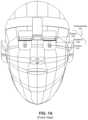
- FIGS. 1 A- 1 Cillustrate a front view, a partial side view and a full side view of a user wearing a partial electronic see-through HMD, according to some embodiments.
- the HMDmay be mounted to the user's head, for example by a headband or helmet.
- the HMDincludes one or more subassemblies 101 that includes a display 103 , an eyepiece 105 , and an outward facing camera 107 .
- the eyepiece 105occludes a central portion of the user's field of view (FOV), but the user may see around the edges of the eyepiece in order to directly view the peripheral zones to each side of the occluded central zone.
- FOVfield of view
- the camera 107captures an image of the occluded central zone, and the eyepiece 105 projects this image (or an enhanced version of the image) from the display 103 into the user's eye.
- the userviews his full field of view as follows.
- the central portion of the field of viewis provided by an electronic image projected via the eyepiece.
- the peripheral portions of the field of vieware directly viewable.
- the central and peripheral portionspreferably are matched in brightness and without gaps, to present a seamless view of the external environment.
- the subassembliespreferably are designed so that the camera, display and eyepiece provide minimal obstruction to the peripheral parts of the field of view.
- FIG. 1shows an HMD with two subassemblies 101 , one for the right eye and one for the left eye, but different numbers of subassemblies may be used. For example, tiling multiple eyepieces and multiple cameras can provide a larger augmented FOV.
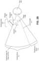
- FIGS. 1 D- 1 Iillustrate different views of the subassemblies 101 , according to some embodiments.
- FIG. 1 Dshows a perspective view of subassemblies 101 , with a sketch of the user's facial features.
- FIGS. 1 E- 1 Ishow views of the subassemblies 101 as it is rotated from a front view to a rear view.
- FIG. 1 Eshows a front view (i.e., looking directly at the user)
- FIG. 1 Fshows a view from the front and to the side
- FIG. 1 Gshows a side view
- FIG. 1 Hshows a view from the rear and to the side
- FIG. 1 Ishows a rear view.
- FIG. 2 Ashows a plan view of a subassembly 101 , illustrating that the eyepiece 105 occludes a portion of an eye's horizontal FOV (HFOV), according to an embodiment.
- FIG. 2 Bshows a side view of the subassembly 101 , illustrating that the eyepiece 105 occludes a portion of the eye's vertical FOV (VFOV), according to an embodiment.
- HFOVhorizontal FOV
- VFOVvertical FOV
- the eyepiece 105occupies a portion of the eye's FOV because the image projected by the eyepiece will occupy this portion of the eye's FOV. This portion of the eye's FOV is referred to as the central zone 111 .
- the central zone 111has a diagonal FOV of 62 degrees.
- the central zone 111may have a diagonal FOV of at least 10 degrees (the usefulness of the HMD may decrease for smaller FOVs).
- the central zonehas a monocular HFOV of 53 degrees (a human eye may have a total monocular HFOV of 120 degrees) and a monocular VFOV that provides the user with a peripheral portion below the eyepiece that is 16.5 degrees (a human eye may have a total monocular VFOV of 80 degrees).
- the central zoneocclusion prevents the eye 109 from directly viewing objects in an external environment within the central zone 111 . In some cases, this may protect the user's eye 109 from bright light sources, such as lasers, in the central zone 111 since there is no direct vision path to the eye 109 .
- the remaining viewable portions of the FOVare referred to as the peripheral zones 113 .
- the eye 109can directly view the peripheral zones 113 of the external environment that are to the sides of and below the central zone 111 .
- the display 103is above the eyepiece and the top of the subassembly 101 is mounted to the HMD.
- the peripheral zone above the central zone 111may not be viewable.
- the peripheral zones 113are equal in size. This is not required though.
- the eyepiece 105is shifted laterally so that one peripheral zone 113 is larger than the other.
- the HMDWhen designing the HMD, it may be advantageous to increase the size of the horizontal peripheral zones and the peripheral zone below the subassembly 101 , while reducing the peripheral zone above the subassembly 101 , in order to increase the total viewable FOV for the user.
- the eyepiece 105blocks different portions of the eye's FOV as the eye 109 moves.
- the location of the subassembly 101 relative to the user's head and the dimensions of the subassembly 101also determine the location and size of the central zone 111 .
- the subassembly 101includes a display 103 , an eyepiece 105 , and an outward facing camera 107 . These components are further described below.
- the camera 107is pointed away from the user's eye 109 to capture images of the external environment in front of the user.
- the camera 107captures images with a FOV that at least includes the central zone 111 (otherwise the displayed image may not complete the user's FOV).
- the camera 107may be behind the eyepiece 105 and the camera dimensions (e.g., width and height) may be smaller than the eyepiece 105 so that the eye 109 cannot see the camera 107 . That is, the camera 107 does add further occlusion beyond that of just the eyepiece.
- the camera 107may be aligned to have a same line of sight as the eye 109 . Said differently, the camera 107 may be aligned with the user's line of sight when the user is looking at the center of the eyepiece 105 . However, this alignment is not required. For example, the camera can be offset in the temporal direction to reduce any obscuration seen by the opposite eye. In addition to capturing images that will be displayed to the user, images from the camera can be used for head, body, and hand tracking. It is desirable for the camera to have a resolution and a bit depth that provides a reasonably good image of the external environment.
- the display 103displays images (e.g., a video) that are projected by the eyepiece 105 to the eye 109 in real-time or near real-time.
- the projected imagesmay include images captured by the camera 107 to complete the user's FOV (e.g., see FIG. 3 and related description).
- the imagesmay be VR images or symbology (e.g., generated by an external computer).
- the camera optics and the eyepiece opticsintroduce distortion and other undesired image artifacts. These may be accounted for by predistorting or reversing the distortion in the image on the display 103 (e.g., using an external computer).
- the camera opticsmay be designed to cancel out the eyepiece optics, or vice versa.
- the displayenables the HMD to display high contrast images and enables a user to operate in external environments with high ambient light.
- the eyepiece 105is an optical component that projects light from the display 103 to the eye 109 .
- the eyepiece 105may be a compact, freeform, frameless prism eyepiece.
- Other examples of eyepieces 105include compact waveguide eyepieces, conventional spherical or aspheric eyepieces, polarization-based “pancake optics” or other freeform optical systems.
- the eyepiece 105may completely or partially prevent light in the central zone 111 from entering the eye 109 .
- outward facing surfaces of the eyepiece 105may be opaque.
- the distance between the eyepiece 105 and the eye(referred to as the eye relief) may be at least 12 millimeters.
- the eyepiece 105may have an eyebox of at least 6 millimeters.
- FIG. 3is a scene of the external environment as viewed by the eye 109 , according to an embodiment.
- the sceneincludes a central zone 111 , which is marked by the heavy border, and peripheral zones 113 that partially surround the central zone 111 .
- the central zone 111is the portion of the FOV occluded by the eyepiece 105 .
- objects behind the eyepiece 105e.g., the tree 307
- the eyepiece 105projects an image 305 of the central zone 111 .
- the projected image 305is recorded by a camera 107 hidden behind the eyepiece 105 .
- the projected image 305completes the FOV of the external scene, for example, so that an image of the tree 307 is presented to the eye 109 .
- the HMDallows the user to view a digital representation of the external environment (through the eyepiece) without the HMD blocking peripheral zones of the eye's FOV.
- the usercan look below the eyepiece to see their body or equipment such as a desktop, mouse, or joystick.
- the usercan directly see their feet while walking, which may be important for safe locomotion.
- a video processor or computerpredistorts the imagery to compensate for the camera lens distortion and/or the eyepiece distortion.
- the camera lens distortionbalances the eyepiece distortion, where, for example, the eyepiece 105 has negative distortion (barrel distortion) and the camera lens is designed with positive (pincushion) distortion to balance it out.
- the camera 107may be mechanically aligned to the eyepiece 105 using mechanical fiducials or measurements from the camera 107 to the eyepiece 105 or its housing.
- fine alignmentcan be performed in a number of ways.
- the camera imagerycan be shifted electronically on the camera.
- the display imagerycan also be electronically shifted on the microdisplay. If a video processor or computer is used, it can digitally shift the imagery to align it with the real world. It is desirable for the camera to be rigidly held with respect to the eyepiece 105 , so that the camera 107 does not shift over time or as the user moves around.
- Initial alignment of the cameracan also be done electronically.
- the projected images 305may be enhanced images compared to the images captured by the camera 107 .
- the projected images 305include electronic information overlaid on the image, such as AR information (e.g., avatars, symbology, structures, etc.).
- AR image object 309is overlaid onto an image of the central zone 111 . Since the projected image 305 is a digital image, the AR object 309 does not appear washed out or transparent compared to real objects in the external environment.
- the AR object 309was displayed by a conventional optical see-through HMD, portions of the tree 307 behind the AR object 309 would be visible, and therefore, the AR object 309 would appear transparent, appear semi-transparent, and/or rendered with low contrast.
- enhanced imagesmay be processed images that make them easier for the user to view.
- image filterse.g., noise reduction, sharpening, blurring, etc.
- the image brightness and contrastis adjusted so that the projected image 305 has a brightness similar to the brightness of natural light from the external environment. This can be done manually or automatically e.g., via an ambient light sensor.
- the physical dimensions of the eyepiece 105may be approximately similar to the dimensions of the eyepiece FOV. Additionally, it is desirable to reduce or eliminate mechanical structures on sides of the eyepiece 105 .
- the eyepiece 105includes a thin frame on one or more edges 115 for mechanical support (e.g., less than 3 or 1 millimeter). In the examples of the FIGS. 2 A- 2 B , the lateral edges 115 A and the bottom edge 115 B of the eyepiece 105 are frameless.
- edges 115 of the eyepiece 105may be tapered so that they do not protrude into the user's line of sight 117 .
- An edge 115may also be referred to as a side of the eyepiece 105 .
- FIGS. 4 A- 4 Billustrate the use of right-eye and left-eye subassemblies, according to some embodiments.
- FIG. 4 Aillustrates a left subassembly 101 L in front of the left eye 109 L and a right subassembly 101 R in front of the right eye 109 L. The HFOV of each eye is also indicated.
- FIG. 4 Bis similar to FIG. 4 A , except the user is looking to the left. While the subassemblies 101 are located at a same location relative to each eye 109 , this is not required. For example, the location of the left subassembly 101 L may be shifted in a nasal or temporal direction compared to the location of the right subassembly 101 R.
- the subassembliesare designed so that an eye 109 cannot “see” components of the other eye's subassembly 101 , even when looking in that direction. For example, as illustrated in FIG. 4 B , despite the right eye 109 R looking in the nasal direction (i.e., to the left), the right eye 109 R does not see the left-eye subassembly 101 L.
- an eye 109may be able to see one or more components of an opposite subassembly 101 .
- an eye 109may not be able see the eyepiece 105 but may be able to see the camera 107 and/or display 103 of the opposite subassembly 101 .
- the eye 109may not be able to see the camera 107 but may be able to see the display 103 of the opposite subassembly 101 .
- an eye 109may not be able to see an opposite subassembly 101 if the eye looks forward, but it may be able to see one or more components of the opposite subassembly if the eye looks in the nasal direction.
- the left-eye subassemblymay block part of the right eye's FOV.
- the left eye 109may see the part of the external environment that is blocked from the right eye's FOV. In such a way, obscurations to the binocular FOV may be reduced or eliminated.
- the peripheral zones and central zones of the right subassembly and the left subassemblymay provide a continuous binocular field of view to the user.
- the subassembliesresult in monocular obscurations but do not result in binocular obscurations. In some embodiments this is only the case in the HFOV.
- the dimensions and locations of a subassembly 101may be based on the locations and FOVs of each eye 109 .
- the visibility of a subassembly 101is related to its forward projection (i.e., the thickness of the subassembly away from the eye). Subassemblies 101 with forward projections that are too large may eliminate or significantly reduce peripheral zones 113 in the nasal direction.
- the subassembly 101may have a forward projection that induces a binocular obscuration where neither eye 109 can see a portion of the external environment within a field of view.
- the camera 107is offset in the temporal direction to reduce the portion of the opposite subassembly 101 seen by the eye 109 .
- the camera 107may have a lens wide enough to capture the entire central zone 111 .
- the components illustrated and describedcan include any electronics and/or computer instructions that may be embodied in digital or analog circuits. This may be implemented using any one or more of application specific integrated circuits (ASICs), field-programmable gate arrays (FPGAs), and general-purpose computing circuits, along with corresponding memories and computer program instructions for carrying out the described operations.
- ASICsapplication specific integrated circuits
- FPGAsfield-programmable gate arrays
- general-purpose computing circuitsalong with corresponding memories and computer program instructions for carrying out the described operations.
- the specifics of these componentsare not shown for clarity and compactness of description.
Landscapes
- Engineering & Computer Science (AREA)
- Physics & Mathematics (AREA)
- General Engineering & Computer Science (AREA)
- General Physics & Mathematics (AREA)
- Theoretical Computer Science (AREA)
- Human Computer Interaction (AREA)
- Optics & Photonics (AREA)
- Multimedia (AREA)
- Signal Processing (AREA)
Abstract
Description
Claims (26)
Priority Applications (1)
| Application Number | Priority Date | Filing Date | Title |
|---|---|---|---|
| US16/699,683US11567323B2 (en) | 2019-12-01 | 2019-12-01 | Partial electronic see-through head-mounted display |
Applications Claiming Priority (1)
| Application Number | Priority Date | Filing Date | Title |
|---|---|---|---|
| US16/699,683US11567323B2 (en) | 2019-12-01 | 2019-12-01 | Partial electronic see-through head-mounted display |
Publications (2)
| Publication Number | Publication Date |
|---|---|
| US20210168270A1 US20210168270A1 (en) | 2021-06-03 |
| US11567323B2true US11567323B2 (en) | 2023-01-31 |
Family
ID=76091356
Family Applications (1)
| Application Number | Title | Priority Date | Filing Date |
|---|---|---|---|
| US16/699,683ActiveUS11567323B2 (en) | 2019-12-01 | 2019-12-01 | Partial electronic see-through head-mounted display |
Country Status (1)
| Country | Link |
|---|---|
| US (1) | US11567323B2 (en) |
Families Citing this family (4)
| Publication number | Priority date | Publication date | Assignee | Title |
|---|---|---|---|---|
| US11567323B2 (en)* | 2019-12-01 | 2023-01-31 | Vision Products, Llc | Partial electronic see-through head-mounted display |
| IL280838B2 (en)* | 2021-02-11 | 2023-07-01 | Elbit Systems Ltd | System and method for removing obstructing objects in a head mounted display |
| WO2023157774A1 (en)* | 2022-02-21 | 2023-08-24 | 国立大学法人東海国立大学機構 | Electronic goggles |
| US20250094016A1 (en)* | 2023-09-18 | 2025-03-20 | Apple Inc. | Systems and methods of motion-based user interfaces |
Citations (27)
| Publication number | Priority date | Publication date | Assignee | Title |
|---|---|---|---|---|
| US3614314A (en)* | 1967-03-21 | 1971-10-19 | Bendix Corp | Optical display means for an all-weather landing system of an aircraft |
| US4775217A (en)* | 1981-10-14 | 1988-10-04 | Gec Avionics Limited | Night vision viewing system |
| US4902116A (en)* | 1987-06-03 | 1990-02-20 | Gec-Marconi Limited | Helmet display systems |
| US5189512A (en)* | 1991-07-01 | 1993-02-23 | Camair Research, Inc. | Helmet integrated display system |
| US5903395A (en)* | 1994-08-31 | 1999-05-11 | I-O Display Systems Llc | Personal visual display system |
| US6040945A (en)* | 1996-03-11 | 2000-03-21 | Seiko Epson Corporation | Head mount display device |
| US6160666A (en)* | 1994-02-07 | 2000-12-12 | I-O Display Systems Llc | Personal visual display system |
| US20020089469A1 (en)* | 2001-01-05 | 2002-07-11 | Cone George W. | Foldable head mounted display system |
| US6560029B1 (en)* | 2001-12-21 | 2003-05-06 | Itt Manufacturing Enterprises, Inc. | Video enhanced night vision goggle |
| US6937400B2 (en)* | 2001-07-23 | 2005-08-30 | Ck Management Ab | Method and device for image display |
| US20100321409A1 (en)* | 2009-06-22 | 2010-12-23 | Sony Corporation | Head mounted display, and image displaying method in head mounted display |
| US20110250962A1 (en)* | 2010-04-09 | 2011-10-13 | Feiner Steven K | System and method for a 3d computer game with true vector of gravity |
| US20110248905A1 (en)* | 2010-04-08 | 2011-10-13 | Sony Corporation | Image displaying method for a head-mounted type display unit |
| US20110248904A1 (en)* | 2010-04-08 | 2011-10-13 | Sony Corporation | Head mounted display and optical position adjustment method of the same |
| US20120120103A1 (en)* | 2010-02-28 | 2012-05-17 | Osterhout Group, Inc. | Alignment control in an augmented reality headpiece |
| US8482859B2 (en) | 2010-02-28 | 2013-07-09 | Osterhout Group, Inc. | See-through near-eye display glasses wherein image light is transmitted to and reflected from an optically flat film |
| US20140085190A1 (en)* | 2012-09-26 | 2014-03-27 | Dolby Laboratories Licensing Corporation | Display, Imaging System and Controller for Eyewear Display Device |
| US8867139B2 (en) | 2012-11-30 | 2014-10-21 | Google Inc. | Dual axis internal optical beam tilt for eyepiece of an HMD |
| US8982471B1 (en) | 2012-01-04 | 2015-03-17 | Google Inc. | HMD image source as dual-purpose projector/near-eye display |
| US9101279B2 (en)* | 2006-02-15 | 2015-08-11 | Virtual Video Reality By Ritchey, Llc | Mobile user borne brain activity data and surrounding environment data correlation system |
| US20150268473A1 (en)* | 2014-03-18 | 2015-09-24 | Seiko Epson Corporation | Head-mounted display device, control method for head-mounted display device, and computer program |
| US20160238850A1 (en) | 2015-02-17 | 2016-08-18 | Tsai-Hsien YANG | Transparent Type Near-eye Display Device |
| US20160328882A1 (en)* | 2015-05-04 | 2016-11-10 | Google Inc. | Pass-through display of captured imagery |
| US20170068119A1 (en)* | 2014-02-19 | 2017-03-09 | Evergaze, Inc. | Apparatus and Method for Improving, Augmenting or Enhancing Vision |
| US20190265480A1 (en)* | 2018-02-23 | 2019-08-29 | Samsung Electronics Co., Ltd. | Head-mounted electronic device |
| US20200111232A1 (en)* | 2018-10-08 | 2020-04-09 | Microsoft Technology Licensing, Llc | Real-world anchor in a virtual-reality environment |
| US20210168270A1 (en)* | 2019-12-01 | 2021-06-03 | SA Photonics, Inc. | Partial electronic see-through head-mounted display |
- 2019
- 2019-12-01USUS16/699,683patent/US11567323B2/enactiveActive
Patent Citations (33)
| Publication number | Priority date | Publication date | Assignee | Title |
|---|---|---|---|---|
| US3614314A (en)* | 1967-03-21 | 1971-10-19 | Bendix Corp | Optical display means for an all-weather landing system of an aircraft |
| US4775217A (en)* | 1981-10-14 | 1988-10-04 | Gec Avionics Limited | Night vision viewing system |
| US4902116A (en)* | 1987-06-03 | 1990-02-20 | Gec-Marconi Limited | Helmet display systems |
| US5189512A (en)* | 1991-07-01 | 1993-02-23 | Camair Research, Inc. | Helmet integrated display system |
| US6160666A (en)* | 1994-02-07 | 2000-12-12 | I-O Display Systems Llc | Personal visual display system |
| US5903395A (en)* | 1994-08-31 | 1999-05-11 | I-O Display Systems Llc | Personal visual display system |
| US6040945A (en)* | 1996-03-11 | 2000-03-21 | Seiko Epson Corporation | Head mount display device |
| US20020089469A1 (en)* | 2001-01-05 | 2002-07-11 | Cone George W. | Foldable head mounted display system |
| US6937400B2 (en)* | 2001-07-23 | 2005-08-30 | Ck Management Ab | Method and device for image display |
| US6560029B1 (en)* | 2001-12-21 | 2003-05-06 | Itt Manufacturing Enterprises, Inc. | Video enhanced night vision goggle |
| US9101279B2 (en)* | 2006-02-15 | 2015-08-11 | Virtual Video Reality By Ritchey, Llc | Mobile user borne brain activity data and surrounding environment data correlation system |
| US20100321409A1 (en)* | 2009-06-22 | 2010-12-23 | Sony Corporation | Head mounted display, and image displaying method in head mounted display |
| US20120120103A1 (en)* | 2010-02-28 | 2012-05-17 | Osterhout Group, Inc. | Alignment control in an augmented reality headpiece |
| US8482859B2 (en) | 2010-02-28 | 2013-07-09 | Osterhout Group, Inc. | See-through near-eye display glasses wherein image light is transmitted to and reflected from an optically flat film |
| US8570242B2 (en)* | 2010-04-08 | 2013-10-29 | Sony Corporation | Image displaying method for a head-mounted type display unit |
| US20110248905A1 (en)* | 2010-04-08 | 2011-10-13 | Sony Corporation | Image displaying method for a head-mounted type display unit |
| US20110248904A1 (en)* | 2010-04-08 | 2011-10-13 | Sony Corporation | Head mounted display and optical position adjustment method of the same |
| US20110250962A1 (en)* | 2010-04-09 | 2011-10-13 | Feiner Steven K | System and method for a 3d computer game with true vector of gravity |
| US8982471B1 (en) | 2012-01-04 | 2015-03-17 | Google Inc. | HMD image source as dual-purpose projector/near-eye display |
| US9720231B2 (en)* | 2012-09-26 | 2017-08-01 | Dolby Laboratories Licensing Corporation | Display, imaging system and controller for eyewear display device |
| US20140085190A1 (en)* | 2012-09-26 | 2014-03-27 | Dolby Laboratories Licensing Corporation | Display, Imaging System and Controller for Eyewear Display Device |
| US8867139B2 (en) | 2012-11-30 | 2014-10-21 | Google Inc. | Dual axis internal optical beam tilt for eyepiece of an HMD |
| US10459254B2 (en)* | 2014-02-19 | 2019-10-29 | Evergaze, Inc. | Apparatus and method for improving, augmenting or enhancing vision |
| US20170068119A1 (en)* | 2014-02-19 | 2017-03-09 | Evergaze, Inc. | Apparatus and Method for Improving, Augmenting or Enhancing Vision |
| US20200004052A1 (en)* | 2014-02-19 | 2020-01-02 | Evergaze, Inc. | Apparatus and Method for Improving, Augmenting or Enhancing Vision |
| US20150268473A1 (en)* | 2014-03-18 | 2015-09-24 | Seiko Epson Corporation | Head-mounted display device, control method for head-mounted display device, and computer program |
| US20160238850A1 (en) | 2015-02-17 | 2016-08-18 | Tsai-Hsien YANG | Transparent Type Near-eye Display Device |
| US20160328882A1 (en)* | 2015-05-04 | 2016-11-10 | Google Inc. | Pass-through display of captured imagery |
| US11024082B2 (en)* | 2015-05-04 | 2021-06-01 | Google Llc | Pass-through display of captured imagery |
| US20190265480A1 (en)* | 2018-02-23 | 2019-08-29 | Samsung Electronics Co., Ltd. | Head-mounted electronic device |
| US10989924B2 (en)* | 2018-02-23 | 2021-04-27 | Samsung Electronics Co., Ltd | Head-mounted electronic device |
| US20200111232A1 (en)* | 2018-10-08 | 2020-04-09 | Microsoft Technology Licensing, Llc | Real-world anchor in a virtual-reality environment |
| US20210168270A1 (en)* | 2019-12-01 | 2021-06-03 | SA Photonics, Inc. | Partial electronic see-through head-mounted display |
Non-Patent Citations (1)
| Title |
|---|
| U.S. Appl. No. 15/605,741, filed May 25, 2017, Inventor Michael P. Browne, James A. Davey, Martin Vasquez. |
Also Published As
| Publication number | Publication date |
|---|---|
| US20210168270A1 (en) | 2021-06-03 |
Similar Documents
| Publication | Publication Date | Title |
|---|---|---|
| US11567323B2 (en) | Partial electronic see-through head-mounted display | |
| US6078427A (en) | Smooth transition device for area of interest head-mounted display | |
| US8994614B2 (en) | Head mountable display | |
| US10495885B2 (en) | Apparatus and method for a bioptic real time video system | |
| US6222675B1 (en) | Area of interest head-mounted display using low resolution, wide angle; high resolution, narrow angle; and see-through views | |
| US20170256095A1 (en) | Blocking screen in Augmented Reality | |
| US9470893B2 (en) | Head mountable device | |
| US10890771B2 (en) | Display system with video see-through | |
| US10602033B2 (en) | Display apparatus and method using image renderers and optical combiners | |
| JP2000258723A (en) | Video display device | |
| US11061237B2 (en) | Display apparatus | |
| CN113170090A (en) | head mounted display | |
| CN113272710A (en) | Extending field of view by color separation | |
| CN107102440A (en) | Wear-type/safety cover type locker/hand-held display methods and display device | |
| CN109255838B (en) | Method and device for avoiding double image watching of augmented reality display device | |
| US11514649B2 (en) | Camera for augmented reality display | |
| WO2017208148A1 (en) | Wearable visor for augmented reality | |
| Browne et al. | Electronic see-through head mounted display with minimal peripheral obscuration | |
| CN109963145B (en) | Visual display system and method, and head mounted display device | |
| US12248148B2 (en) | Smart eyeglasses | |
| US11921295B1 (en) | Eyewear with lenses for reduced discrepancy between accommodation and convergence | |
| EP4261768B1 (en) | Image processing system and method | |
| KR102822398B1 (en) | Occlusion apparatus and method for augmented reality display | |
| CN111435195B (en) | Near-Eye Display Structure | |
| CN109963141B (en) | Visual display system and method and head-mounted display device |
Legal Events
| Date | Code | Title | Description |
|---|---|---|---|
| FEPP | Fee payment procedure | Free format text:ENTITY STATUS SET TO UNDISCOUNTED (ORIGINAL EVENT CODE: BIG.); ENTITY STATUS OF PATENT OWNER: SMALL ENTITY | |
| FEPP | Fee payment procedure | Free format text:ENTITY STATUS SET TO SMALL (ORIGINAL EVENT CODE: SMAL); ENTITY STATUS OF PATENT OWNER: SMALL ENTITY | |
| AS | Assignment | Owner name:SA PHOTONICS, INC., CALIFORNIA Free format text:ASSIGNMENT OF ASSIGNORS INTEREST;ASSIGNOR:BROWNE, MICHAEL P.;REEL/FRAME:051380/0050 Effective date:20191203 | |
| STPP | Information on status: patent application and granting procedure in general | Free format text:RESPONSE TO NON-FINAL OFFICE ACTION ENTERED AND FORWARDED TO EXAMINER | |
| STPP | Information on status: patent application and granting procedure in general | Free format text:FINAL REJECTION MAILED | |
| STPP | Information on status: patent application and granting procedure in general | Free format text:RESPONSE AFTER FINAL ACTION FORWARDED TO EXAMINER | |
| STPP | Information on status: patent application and granting procedure in general | Free format text:ADVISORY ACTION MAILED | |
| STPP | Information on status: patent application and granting procedure in general | Free format text:DOCKETED NEW CASE - READY FOR EXAMINATION | |
| STPP | Information on status: patent application and granting procedure in general | Free format text:NON FINAL ACTION MAILED | |
| AS | Assignment | Owner name:VISION PRODUCTS, LLC, CALIFORNIA Free format text:ASSIGNMENT OF ASSIGNORS INTEREST;ASSIGNOR:SA PHOTONICS, INC.;REEL/FRAME:058803/0919 Effective date:20211130 | |
| STPP | Information on status: patent application and granting procedure in general | Free format text:RESPONSE TO NON-FINAL OFFICE ACTION ENTERED AND FORWARDED TO EXAMINER | |
| STPP | Information on status: patent application and granting procedure in general | Free format text:FINAL REJECTION MAILED | |
| STPP | Information on status: patent application and granting procedure in general | Free format text:RESPONSE AFTER FINAL ACTION FORWARDED TO EXAMINER | |
| STPP | Information on status: patent application and granting procedure in general | Free format text:NOTICE OF ALLOWANCE MAILED -- APPLICATION RECEIVED IN OFFICE OF PUBLICATIONS | |
| STPP | Information on status: patent application and granting procedure in general | Free format text:AWAITING TC RESP, ISSUE FEE PAYMENT VERIFIED | |
| STPP | Information on status: patent application and granting procedure in general | Free format text:PUBLICATIONS -- ISSUE FEE PAYMENT VERIFIED | |
| STCF | Information on status: patent grant | Free format text:PATENTED CASE |