US11567278B2 - Fiber drop terminal - Google Patents
Fiber drop terminalDownload PDFInfo
- Publication number
- US11567278B2 US11567278B2US17/145,931US202117145931AUS11567278B2US 11567278 B2US11567278 B2US 11567278B2US 202117145931 AUS202117145931 AUS 202117145931AUS 11567278 B2US11567278 B2US 11567278B2
- Authority
- US
- United States
- Prior art keywords
- fiber
- housing
- terminal
- output
- input
- Prior art date
- Legal status (The legal status is an assumption and is not a legal conclusion. Google has not performed a legal analysis and makes no representation as to the accuracy of the status listed.)
- Expired - Lifetime
Links
Images


Classifications
- G—PHYSICS
- G02—OPTICS
- G02B—OPTICAL ELEMENTS, SYSTEMS OR APPARATUS
- G02B6/00—Light guides; Structural details of arrangements comprising light guides and other optical elements, e.g. couplings
- G02B6/46—Processes or apparatus adapted for installing or repairing optical fibres or optical cables
- G02B6/47—Installation in buildings
- G02B6/475—Mechanical aspects of installing cables in ducts or the like for buildings
- G—PHYSICS
- G02—OPTICS
- G02B—OPTICAL ELEMENTS, SYSTEMS OR APPARATUS
- G02B6/00—Light guides; Structural details of arrangements comprising light guides and other optical elements, e.g. couplings
- G02B6/44—Mechanical structures for providing tensile strength and external protection for fibres, e.g. optical transmission cables
- G02B6/4439—Auxiliary devices
- G02B6/444—Systems or boxes with surplus lengths
- G02B6/4441—Boxes
- G02B6/4442—Cap coupling boxes
- G—PHYSICS
- G02—OPTICS
- G02B—OPTICAL ELEMENTS, SYSTEMS OR APPARATUS
- G02B6/00—Light guides; Structural details of arrangements comprising light guides and other optical elements, e.g. couplings
- G02B6/24—Coupling light guides
- G02B6/36—Mechanical coupling means
- G02B6/38—Mechanical coupling means having fibre to fibre mating means
- G02B6/3807—Dismountable connectors, i.e. comprising plugs
- G02B6/3873—Connectors using guide surfaces for aligning ferrule ends, e.g. tubes, sleeves, V-grooves, rods, pins, balls
- G02B6/3885—Multicore or multichannel optical connectors, i.e. one single ferrule containing more than one fibre, e.g. ribbon type
- G—PHYSICS
- G02—OPTICS
- G02B—OPTICAL ELEMENTS, SYSTEMS OR APPARATUS
- G02B6/00—Light guides; Structural details of arrangements comprising light guides and other optical elements, e.g. couplings
- G02B6/24—Coupling light guides
- G02B6/36—Mechanical coupling means
- G02B6/38—Mechanical coupling means having fibre to fibre mating means
- G02B6/3807—Dismountable connectors, i.e. comprising plugs
- G02B6/3897—Connectors fixed to housings, casing, frames or circuit boards
- G—PHYSICS
- G02—OPTICS
- G02B—OPTICAL ELEMENTS, SYSTEMS OR APPARATUS
- G02B6/00—Light guides; Structural details of arrangements comprising light guides and other optical elements, e.g. couplings
- G02B6/44—Mechanical structures for providing tensile strength and external protection for fibres, e.g. optical transmission cables
- G02B6/4439—Auxiliary devices
- G02B6/444—Systems or boxes with surplus lengths
- G02B6/4441—Boxes
- G02B6/4442—Cap coupling boxes
- G02B6/4444—Seals
- G—PHYSICS
- G02—OPTICS
- G02B—OPTICAL ELEMENTS, SYSTEMS OR APPARATUS
- G02B6/00—Light guides; Structural details of arrangements comprising light guides and other optical elements, e.g. couplings
- G02B6/44—Mechanical structures for providing tensile strength and external protection for fibres, e.g. optical transmission cables
- G02B6/4439—Auxiliary devices
- G02B6/444—Systems or boxes with surplus lengths
- G02B6/4441—Boxes
- G02B6/4446—Cable boxes, e.g. splicing boxes with two or more multi fibre cables
- G02B6/44465—Seals
- G—PHYSICS
- G02—OPTICS
- G02B—OPTICAL ELEMENTS, SYSTEMS OR APPARATUS
- G02B6/00—Light guides; Structural details of arrangements comprising light guides and other optical elements, e.g. couplings
- G02B6/44—Mechanical structures for providing tensile strength and external protection for fibres, e.g. optical transmission cables
- G02B6/4439—Auxiliary devices
- G02B6/444—Systems or boxes with surplus lengths
- G02B6/4441—Boxes
- G02B6/44515—Fibre drop terminals with surplus length
- G—PHYSICS
- G02—OPTICS
- G02B—OPTICAL ELEMENTS, SYSTEMS OR APPARATUS
- G02B6/00—Light guides; Structural details of arrangements comprising light guides and other optical elements, e.g. couplings
- G02B6/44—Mechanical structures for providing tensile strength and external protection for fibres, e.g. optical transmission cables
- G02B6/4439—Auxiliary devices
- G02B6/444—Systems or boxes with surplus lengths
- G02B6/44528—Patch-cords; Connector arrangements in the system or in the box
- G—PHYSICS
- G02—OPTICS
- G02B—OPTICAL ELEMENTS, SYSTEMS OR APPARATUS
- G02B6/00—Light guides; Structural details of arrangements comprising light guides and other optical elements, e.g. couplings
- G02B6/44—Mechanical structures for providing tensile strength and external protection for fibres, e.g. optical transmission cables
- G02B6/4439—Auxiliary devices
- G02B6/4457—Bobbins; Reels
- G02B6/4466—
- G—PHYSICS
- G02—OPTICS
- G02B—OPTICAL ELEMENTS, SYSTEMS OR APPARATUS
- G02B6/00—Light guides; Structural details of arrangements comprising light guides and other optical elements, e.g. couplings
- G02B6/44—Mechanical structures for providing tensile strength and external protection for fibres, e.g. optical transmission cables
- G02B6/4439—Auxiliary devices
- G02B6/4471—Terminating devices ; Cable clamps
- G02B6/44775—Cable seals e.g. feed-through
- H—ELECTRICITY
- H04—ELECTRIC COMMUNICATION TECHNIQUE
- H04B—TRANSMISSION
- H04B10/00—Transmission systems employing electromagnetic waves other than radio-waves, e.g. infrared, visible or ultraviolet light, or employing corpuscular radiation, e.g. quantum communication
- H04B10/25—Arrangements specific to fibre transmission
- H04B10/2589—Bidirectional transmission
- H04B10/25891—Transmission components
Definitions
- the present inventionrelates generally to communication networks and, more particularly, to fiber drop terminals for use in optical communications networks.
- High bandwidth communicationsmay allow users to take advantage of advanced communication capabilities, such as voice-over-internet protocol (VoIP) communications, interactive gaming, delivery of high resolution video, such as high definition television (HDTV), as well as the transmission and/or reception of large data files.
- VoIPvoice-over-internet protocol
- HDTVhigh definition television
- ISDNintegrated services digital network
- DSLdigital subscriber line
- ASDLasynchronous digital subscriber line
- cable television co-axial cabletechnologies such as these may provide broadband capabilities to an extent. For example, some DSL services may provide up to approximately 5 Mbits/sec of data. Users may, however, demand even higher bandwidths.
- the above technologiesmay have inadequate bandwidth for some users and/or these technologies may be relatively expensive to deploy and/or maintain.
- PONSpassive optical networks
- a service providermay employ a central office, or head end, containing electronic equipment for placing signals onto optical fibers running to user premises.
- End user premisesmay employ equipment for receiving optical signals from the optical fibers.
- the central office, or head end, transmission equipment and/or the transmission equipment located at the end user premisesmay, respectively, use a laser to inject data onto a fiber in a manner that may not require the use of any active components, such as amplifiers between the central office, or head end, and/or the end user premises.
- any active componentssuch as amplifiers between the central office, or head end, and/or the end user premises.
- only passive optical componentssuch as splitters, optical fibers, connectors and/or splices, may be used between a service provider and an end user premises in PONS.
- PONSmay be attractive to service providers because passive networks may be less costly to maintain and/or operate as compared to active optical networks and/or older copper based networks, such as a public switched telephone network (PSTN).
- PSTNpublic switched telephone network
- PONSmay provide sufficient bandwidth to meet a majority of end users' high bandwidth communication needs into the foreseeable future.
- transmission equipmentmay transmit signals containing voice, data and/or video over a fiber strand to the premises.
- An optical fibermay be split using, for example, passive optical splitters so that signals are dispersed from one fiber (the input fiber) to multiple output fibers running to, for example, user premises from a convergence point in the network.
- An optical fiber routed to a user's premisesmay be routed via a fiber drop terminal en route to the premises.
- signals appearing on one or more optical fibersmay be routed to one or more end user premises.
- Fiber drop terminalsmay be mounted in aerial applications, such as near the tops of utility poles, along multi-fiber and/or multi-conductor copper strands suspended between utility poles. Fiber drop terminals may also be installed in junction boxes mounted at ground level and/or in below-grade vaults where utilities are run below ground.
- Fiber drop terminalsmay be made of injection molded plastic to keep per unit costs as low as possible. Since fiber drop terminals may be exposed to the elements, they may be resistant to water infiltration and/or degradation due to ultraviolet (UV) light. Fiber drop terminal enclosures may be fabricated from UV resistant plastic and/or equipped with gaskets to prevent water infiltration. At times, the plastic used for the enclosure may fatigue and/or crack leading to water and/or water vapor penetration into the interior of the enclosure. The design of existing enclosure mating surfaces, such as gasketed interfaces, may interact in a manner facilitating water and/or water vapor penetration. For example, gasket material may be of an inadequate durometer to provide a weather-tight seal between an enclosure body and/or an enclosure base.
- Existing fiber drop terminalsmay not have sufficient interior space to allow fibers within the enclosures to bend with a radius of at least an industry and/or manufacturer recommended minimum bend radius.
- optical fibersWhen optical fibers are bent with a radius of less than an industry and/or manufacturer recommended minimum, such as 1.75 inches, optical signal losses may result.
- Existing fiber drop terminalsmay have connector orientations that do not facilitate unencumbered and/or ergonomic coupling and/or decoupling of optical fibers/connectors by service and installation personnel (hereafter linesmen). As a result, it may be difficult for a linesman to attach and/or remove connectors in certain situations, such as when servicing a fiber drop terminal mounted on a utility pole using, for example, a ladder and/or a bucket lift.
- Fiber drop terminalsWhen fiber drop terminals are deployed in the field, they may need to be tested prior to connecting subscribers to communication services delivered via the fiber drop terminals. Testing may be required to confirm that optical fibers coupled to the fiber drop terminal are operating properly and that connectors and/or receptacles associated with the fiber drop terminal are installed and/or operating correctly. Testing may be performed by injecting a signal onto a fiber at a central office and measuring the signal with a detector at a fiber drop terminal. A linesman may inject a signal onto a fiber at a central office and then drive to a location having a fiber drop terminal. The linesman may climb a pole and connect a detector to an output receptacle on the fiber drop terminal. The linesman may determine if the signal has a desired signal-to-noise ratio.
- the linesmanmay drive back to the central office and connect the test signal to another fiber associated with the fiber drop terminal.
- the linesmanmay again drive to the terminal and detect the test signal. If a fiber drop terminal has, for example, eight output receptacles, the linesman may repeat the drive to and from the drop terminal eight times. Testing fiber drop terminals using known techniques may be labor intensive and may consume a lot of fuel due to the back and forth trips between the central office and fiber drop terminal locations.
- a fiber drop terminalmay be provided.
- the fiber drop terminalmay include a housing having an outer surface containing a plurality of receptacles, where the housing further has an inner cavity.
- the fiber drop terminalmay include a storage cavity occupying a portion of the inner cavity, where the storage cavity being configured to store a plurality of fiber coils at an angle with respect to the outer surface.
- a fiber drop terminalmay include a first face having a first plurality of output receptacles having a first mounting angle with respect to the first face.
- the fiber drop terminalmay include a second face having a second plurality of output receptacles having a second mounting angle with respect to the second face.
- the fiber drop terminalmay include a mating angle formed by an intersection of the first face and the second face, where the mating angle facilitate access to the first and second plurality of output receptacles.
- a fiber drop terminalmay include a housing that includes a first receptacle support face for receiving a first output receptacle, having a lower edge; a second receptacle support face for receiving a second output receptacle, and having an upper edge; a transition portion located between the lower edge and the upper edge, where the transition portion forms a valley area at the connection with the lower edge; and a gusset contacting the lower edge, the valley and the transition portion, where the gusset is further configured to reinforce the valley area.
- a cylindrical fiber drop terminalmay include an input section having an input channel for receiving an incoming fiber bundle having a plurality of input optical fibers, where the input section further has an input section mating surface and an inner cavity.
- the cylindrical fiber drop terminalmay include a first output section having a first plurality of output receptacles.
- the first output sectionmay further have a first mating surface for mating with the input section mating surface, a second mating surface, and a first inner cavity.
- the cylindrical fiber drop terminalmay include an end cap section having a second inner cavity for storing fiber coils and further having an end cap mating surface for mating with the second mating surface.
- a fiber drop terminalmay include means for receiving an incoming optical signal; means for storing optical fiber at an angled orientation within the fiber drop terminal; and means for making the incoming optical signal available to premises.
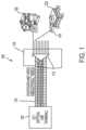
- FIG. 1illustrates a first schematic representation of an exemplary broadband access network that may include passive optical network (PON) components in an implementation consistent with the principles of the invention
- PONpassive optical network
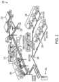
- FIG. 2illustrates a second schematic representation of an exemplary broadband access network that may employ fiber to the premises (FTTP) and/or PON components in an implementation consistent with the principles of the invention
- FIG. 3 Aillustrates an exemplary implementation of a fiber drop terminal that may include a stepped face, consistent with the principles of the invention
- FIG. 3 Billustrates a cut away view of the exemplary implementation the housing illustrated in FIG. 3 A , consistent with the principles of the invention
- FIG. 4illustrates a view of an interior cavity associated with an exemplary implementation of a fiber drop terminal employing an angled fiber management cavity, consistent with the principles of the invention
- FIG. 5illustrates a cross-section of an exemplary implementation of a fiber drop terminal housing employing a fiber management cavity for storing fiber coils at an angled orientation, consistent with the principles of the invention
- FIG. 6illustrates an exemplary implementation of a fiber retention device in accordance with an implementation consistent with the principles of the invention
- FIG. 7 Aillustrates an exemplary implementation of a fiber drop terminal that may include a fiber input channel located in a lower portion of the terminal, consistent with the principles of the invention
- FIG. 7 Billustrates an exemplary implementation of a fiber drop terminal including a fiber input channel located in an upper portion of the terminal, consistent with the principles of the invention
- FIGS. 8 A and 8 Billustrate the exemplary implementations of FIGS. 7 A and 7 B , respectively, in combination with ruggedized multi-fiber input connectors to facilitate a removable interconnection between an incoming fiber bundle and/or an output connector, consistent with the principles of the invention
- FIG. 8 Cillustrates an overhead view of an exemplary implementation of the fiber drop terminal of FIGS. 8 A and/or 8 B showing fiber retention and/or routing techniques that may be employed within the terminals, respectively, consistent with the principles of the invention;
- FIGS. 9 A and 9 Billustrate an exemplary implementation of a fiber drop terminal having a reinforced housing that may include reinforcing gussets at locations that may be associated with regions of adverse stress, consistent with the principles of the invention
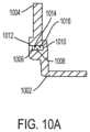
- FIG. 10 Aillustrates an exemplary implementation of an enclosure mating surface utilizing a gasket device to facilitate a weatherproof seal between a housing and a base, consistent with the principles of the invention
- FIG. 10 Billustrates the mating surface of the exemplary implementation of FIG. 10 A in greater detail, consistent with the principles of the invention
- FIG. 11 Aillustrates an exemplary implementation of a mounting bracket that may be used to attach an implementation of a fiber drop terminal to a substantially vertical surface, consistent with the principles of the invention
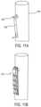
- FIG. 11 Billustrates an exemplary implementation of a fiber drop terminal mounted to a substantially vertical surface via the mounting bracket illustrated in FIG. 11 A , consistent with the principles of the invention
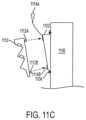
- FIG. 11 Cillustrates an exemplary technique for attaching the fiber drop terminal of FIG. 11 B to the bracket of FIG. 11 A , consistent with the principles of the invention
- FIG. 11 Dillustrates an exemplary implementation of a base module having self-alignment channels to facilitate self-alignment of a fiber drop terminal with a mounting bracket, consistent with the principles of the invention
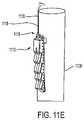
- FIG. 11 Eillustrates the exemplary enclosure of FIG. 11 B along with an exemplary implementation of a top entry fiber optic connector, consistent with the principles of the invention
- FIG. 11 Fillustrates the exemplary enclosure of FIG. 11 B along with an exemplary implementation of a bottom entry fiber optic connector, consistent with the principles of the invention
- FIG. 12 Aillustrates a first exemplary implementation of a fiber drop terminal that may include pry tabs for facilitating removal of an enclosure housing from a base, consistent with the principles of the invention
- FIG. 12 Billustrates a second exemplary implementation of a fiber drop terminal employing pry tabs, consistent with the principles of the invention
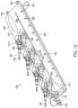
- FIG. 13illustrates an exemplary implementation of a fiber drop terminal including recessed pockets for supporting output receptacles that may be adapted to receive output connectors, consistent with the principles of the invention
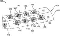
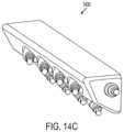
- FIGS. 14 A-Cillustrate various aspects of an exemplary implementation of a fiber drop terminal 1400 having tiered receptacles mounted on faces having an angular association with each other, consistent with the principles of the invention
- FIG. 15illustrates an exemplary implementation of a fiber drop terminal having output receptacles and contoured surfaces associated with receptacle pocket areas, consistent with the principles of the invention
- FIG. 16illustrates an exemplary implementation of a fiber drop terminal employing a cylindrical enclosure, consistent with the principles of the invention
- FIG. 17 Aillustrates an implementation of a fiber drop terminal 1700 employing loop back-plugs, consistent with the principles of the invention
- FIG. 17 Billustrates an exemplary flow diagram illustrating a method for testing a fiber drop terminal used in a communication network consistent with the principles of the invention
- FIG. 18illustrates a flow chart showing an exemplary method for routing fiber strands within a fiber drop terminal employing an angled fiber management system, consistent with the principles of the invention
- FIG. 19illustrates a flow chart showing an exemplary method for installing a fiber drop terminal using a bracket, consistent with the principles of the invention.
- FIG. 20illustrates a flow chart showing an exemplary method for installing fiber drop terminals and/or output connectors onto a multi-fiber strand prior to deployment in the field, consistent with the principles of the invention.
- FIG. 1illustrates a first schematic representation of an exemplary broadband access network 100 that may include PON components in an implementation consistent with the principles of the invention.
- Network 100may include an optical line terminal (OLT) 102 , a voice input 104 , a data input 106 , a video input 108 , a wavelength division multiplexed (WDM) fiber 110 , a passive optical splitter (POS) 112 , a fiber distribution hub (FDH) 114 , optical network terminals (ONTs) 116 and 118 , a residence 120 , and an office building 122 .
- OLToptical line terminal
- POSpassive optical splitter
- FDHfiber distribution hub
- OLT 102may include any device capable of placing data onto one or more optical fibers.
- OLT 102may include a head end controller adapted to inject signals onto one or more optical fibers.
- Network 100may employ OLT 102 for receiving input data from one or more service networks.
- OLT 102may receive voice input 104 , data input 106 and/or video input 108 from one or more service networks associated with, for example, a telecommunications provider, a multi-media provider, and/or a cable television provider.
- OLT 102may queue and/or output a multiplexed data stream over one or more optical fibers 110 .
- an exemplary implementation of OLT 102may output voice at a wavelength on the order of 1490 nanometers (nm), data at a wavelength on the order of 1310 nm and/or video at a wavelength on the order of 1550 nm.
- WDM fiber 110may include any medium capable of carrying optical signals from a source to a destination. WDM fiber 110 may transport data from a proximal, or input, end using techniques, such as WDM, to a distal, or output, end.
- POS 112may include any device capable of accepting an incoming optical signal and splitting the optical signal into two or more output signals. POS 112 may receive data by way of a single fiber (the input fiber) and split the data across two or more output fibers. For example, POS 112 may split incoming data across 2, 4, 8, 16, 32, or more output fibers. In an exemplary implementation, each output fiber is associated with an end user, such as a residence 120 and/or a commercial end user in office building 122 .
- POS 112may be located in both indoor and outdoor environments. For example, POS 112 may be located in a central office/head end, environmentally secure cabinets, and/or in outdoor enclosures such as fiber drop terminals. In one implementation, POS 112 may include optical splitters that are prepackaged in optical splitter module housings. Packaging POS 112 in an optical splitter cassette, or housing, may provide protective packaging to facilitate easy handling of otherwise fragile splitter components by linesmen.
- An optical splitter cassettemay include any device capable of housing one or more assemblies used for splicing an incoming fiber into two or more outgoing fibers.
- FDH 114may include any device capable of housing POS 112 .
- FDH 114may include a re-enterable weather tight enclosure capable of holding one or more POSs 112 .
- Exemplary implementations of FDH 114are described in U.S. patent application Ser. No. 10/714,814 entitled Systems and Methods for Fiber Distribution and Management, filed on Nov. 17, 2003, and U.S. patent application Ser. No. 10/991,135 entitled Systems and Methods for Optical Fiber Distribution and Management, filed on Nov. 17, 2004, the entire contents of which are, respectively, hereby incorporated by reference herein. Implementations of FDH 114 may allow easy re-entry by linesmen and/or other service personnel.
- a linesmanmay access FDH 114 to install one or more POSs 112 , to make fiber connections available to a subscriber, and/or to troubleshoot POS 112 .
- POS 112may be mounted in FDH 114 using cassettes operating in conjunction with a fiber patch panel to facilitate routing of fiber jumpers.
- Fiber jumpersmay be used to connect the splitter outputs of POS 112 to one or more subscriber ports on the fiber patch panel.
- a subscriber portmay facilitate connection of an optical signal from a central office and/or head end to a customer premises.
- FDH 114may, for example, serve on the order of 144 to 432 splitter ports and/or premises, and may include multiple distribution cables, connectorized and/or fusion spliced between OLT 102 and POS 112 located within, for example, FDH 114 .
- Network 100may be designed to achieve low optical insertion loss in order to achieve maximum network reach from electronics having fixed power output.
- Each optical component and subsystem utilized in the networkmay be optimized to provide minimum insertion loss.
- an optical loss budget in an exemplary implementationmay be approximately 23 to 25 dB with 1:32 passive splitting.
- the components and factors contributing to the optical lossmay include splitters (1:32, single or cascaded), WDMs, connectors such as to OLT 102 , POS 112 , a fiber patch panel, a fiber drop, and/or ONT 116 , 118 , fiber attenuation at various frequencies, such as, wavelengths of 1310 nm, 1490 nm, and/or 1550 nm, and/or fiber splices.
- ONTs 116 , 118may include any device capable of receiving an incoming optical signal and making it available to a destination.
- end user locationsuch as residence 120
- ONT 116may use ONT 116 to receive a multiplexed incoming optical signal and make it available to an end user device, such as a computer.
- ONT 116may act as a demultiplexer by accepting a multiplexed data stream containing voice, video, and/or data.
- ONT 116may demultiplex the incoming data stream and provide a separate voice channel to a user's telephone, a separate video channel to a television set, and/or a separate data channel to a computer.
- FIG. 2illustrates a second schematic representation of an exemplary broadband access network 200 that may employ FTTP and/or PON components in an implementation consistent with the principles of the invention.
- Network 200may include a circuit switch/OLT 202 , a service area interface (SAI) 204 , a splitter hub 206 , one or more residential ONTs 208 , one or more small business ONTs 210 , one or more office park ONTs 212 , FTTP 214 , utility pole 216 , downstream splitter 218 , and fiber drop terminal 220 .
- Circuit switch/OLT 202may include central office equipment for placing optical signals onto FTTP 214 .
- circuit switch/OLT 202may convert analog signals associated with a PSTN to optical signals that are conveyed to FTTP 214 .
- SAI 204may include any device capable of splitting an incoming signal into multiple outgoing signals.
- SAI 204may receive an optical fiber from circuit switch/ONT 202 .
- SAI 204may split data on the incoming fiber into multiple outgoing data flows on a like number of outgoing optical fibers.
- SAI 204may split an incoming signal into, for example, 32 output signals using a 1 ⁇ 32 splitter.
- Splitter hub 206may include any device capable of retaining SAI 204 .
- splitter hub 206may be implemented as FDH 114 as discussed in conjunction with FIG. 1 .
- Residential ONT 208may include any device capable of receiving an incoming optical signal and making it available to a destination. Residential ONT 208 may operate in a manner similar to ONTs 116 and 118 described in conjunction with FIG. 1 .
- Small business ONT 210may include any device capable of receiving an incoming optical signal and making it available to a destination, such as a small business. Small business ONT 210 may serve a single small business and/or may serve a group of small businesses, such as businesses co-located in a strip mall and/or small commercial building.
- Office park ONT 212may include any device capable of receiving an incoming optical signal and making it available to a destination. Office park ONT 212 may operate to serve an office park including one or more buildings and/or offices.
- Optical signalsmay be conveyed from SAI 204 and/or splitter hub 206 by FTTP 214 .
- FTTP 214may include one or more optical media capable of conveying optical signals from a source to a destination.
- Optical mediamay include optical fibers.
- Optical fibers used in outdoor installationsmay include a protective sheath surrounding the optical medium to provide rigidity, strength, durability, color coding, strain relief and/or protection from the elements such as water and/or UV radiation.
- FTTP 214may include a single fiber and/or multiple fibers.
- the multiple fibersmay be deployed in a multi-fiber strand, or bundle, surrounded by a protective bundle-sheath.
- the bundle-sheathmay operate to provide rigidity, strength, durability, color coding, strain relief and/or protection from the elements such as water and/or UV radiation.
- Bundled fibersmay include breakouts at determined locations. Breakout refers to a location on a bundle-sheath where one or more optical fibers exit the interior portion of the bundle-sheath and are made available to other devices, such as residential ONT 208 , small business ONT 210 , office park ONT 212 and/or fiber drop terminal 220 .
- FTTP 214may be suspended above grade using one or more utility poles 216 .
- Utility pole 216may include any device capable of supporting an optical fiber.
- Utility pole 216may include conventional utility poles and/or optical fiber supporting devices used on structures, such as the exterior surfaces of buildings.
- a fiber drop terminal 220may be used in conjunction with utility pole 216 .
- Utility pole 216may be used to support conventional copper wire strands such as those used for plain old telephone service (POTS), those used for cable television (CATV) and/or FTTP 214 .
- POTSplain old telephone service
- CATVcable television
- Network 200may include one or more downstream splitters 218 .
- a down stream splitter 218may include any device capable of splitting an incoming optical signal into two or more outgoing optical signals.
- Downstream splitter 218may include a reduced splitting capacity as compared to splitter hub 206 .
- downstream splitter 218may include a 1 ⁇ 2, 1 ⁇ 4 and/or 1 ⁇ 8 splitter.
- Downstream splitter 218may include passive and/or active splitting devices operating alone or on combination.
- downstream splitter 218may be incorporated into fiber drop terminal 220 .
- Fiber drop terminal 220may include any device capable of receiving one or more input fibers and distributing optical communication signals traversing the input fibers to one or more output fibers.
- Fiber drop terminals 220are used to interface between distribution cables and drop cables in a PON application.
- Fiber drop terminal 220may be manufactured from injection molded plastic and may include an enclosure body, or housing, and a base.
- Fiber drop terminal 220may be configured by splicing a multi-fiber cable at a branch, or breakout, point. For example, a large fiber count distribution cable may be spliced to obtain eight fibers to connect to a fiber drop terminal having eight output receptacles.
- a single cable having one or more optical fibers thereinmay depart the splice location and serve as an input, or feed, cable to fiber drop terminal 220 .
- a feed cablemay have a central tube housing a plurality of individual optical fibers. Inside fiber drop terminal 220 , the multi-fiber feed cable may be separated into individual fibers and then terminated on individual rugged outdoor receptacles, connectors and/or adapters located on an exterior surface of the enclosure. Fiber drop terminal 220 may thus used to stage the PON cabling system near premises locations, such as a residence 120 or office building 122 , so that when a subscriber requests service, a simple connectorized drop cable can be quickly and easily connected between fiber drop terminal 220 and circuit switch/ONT 202 and a customer premises.
- Fiber drop terminal 220may also be coupled to a feed cable at a manufacturing or assembly plant.
- fiber drop terminal 220may be installed on a multi-fiber stranded feed cable at a predetermined location.
- a breakoutmay be terminated with an input connector at a manufacturing plant.
- a fiber drop terminal 220may be attached to the input connector via an input receptacle. Implementations of fiber drop terminal 220 may take many forms. Several exemplary implementations are described herein.
- the network architecture described in conjunction with FIGS. 1 and 2may operate in a point to multi-point PON configuration utilizing, for example, 1:32 splitters at FDH 114 or splitter hub 206 .
- the network architecturemay be fiber rich, such as in a 1:1 distribution arrangement between FDH 114 and a customer's premise, such as residence 120 , and/or the network architecture can be diluted, such as in a 1:X arrangement where X is an integer larger than 1.
- the broadband services capability of network 100 and/or network 200 for distributing source informationmay include data signals, at for example 622 Mbps ⁇ 155 Mbps (shared), video signals, at for example 860 MHz for approximately 600 analog and/or digital channels and/or high definition television (HDTV), and/or video on demand (VOD).
- Source informationmay consist of data, such as, voice, video, text, still images, numerical data and/or control data.
- Source informationmay originate at a source location, such as a telecommunications service provider (hereinafter service provider). Signaling may be accomplished using WDM and/or fiber sharing.
- Network 100may include ONTs 116 and 118 that are scalable, provide high bandwidth, and/or support multi-service applications that can service residences and/or small to medium sized businesses.
- Network 100may include passive components that are located outside the plant, i.e., outside the service provider's building, and require minimal maintenance, since active components, such as amplifiers, may not be required.
- Implementations of networks 100 and/or 200may include digital subscriber plug-in line cards having a broadband terminal adapters configured to receive digitally multiplexed broadband data streams and output one or more demultiplexed broadband data streams for one or more subscriber loops.
- FIG. 3 Aillustrates an exemplary implementation of a fiber drop terminal 300 that may include a stepped face, consistent with the principles of the invention.
- Stepped face terminal 300may include a base 302 , a fastener guide 304 , a housing 306 having a fiber management portion 308 , one or more output receptacles 310 A-D, an output connector 312 , an output fiber 314 , an input channel 316 , and an incoming fiber bundle 318 .
- Terminal 300may be deployed in a number of installed environments including aerial (such as near the top of a utility pole), pedestal (such as cabinets accessible when standing on grade), and/or below grade (such as in below grade vaults and/or sealed enclosures).
- Terminal 300may consist of two molded plastic enclosure parts separated by a flexible sealing interface that operates to seal an internal cavity against the elements.
- terminalmay consist of base 302 and housing, or body, 306 .
- Terminal 300may include base 302 that can be releasably attached to housing 306 using, for example, fasteners, keyed retainers, clamping devices, etc.
- Base 302may include a substantially flat shape configured to retain a gasket and/or other sealing device along a base mounting surface that may be releasably coupled to a corresponding housing mounting surface associated with housing 306 .
- Base 302may be adapted for attachment to a surface, such as a utility pole, using fasteners, such as nails, and/or screws, via fastener guide 304 .
- Housing 306may be shaped so as to form a cavity for housing optical fibers. Housing 306 may include an outer surface having penetrations passing therethrough for receiving, for example, output receptacles 310 A-D. Housing 306 may be shaped so that an upper surface of base 302 operates to form an enclosed area in conjunction with the cavity when coupled to housing 306 along a gasketed interface. Housing 306 may be configured so that a portion of the inner cavity operates as a fiber management portion 308 for storing excess optical fiber. In one implementation, housing 306 may be configured to have a depth 320 sufficient to allow storage of fiber coils in an angular orientation so as to facilitate maintaining a determined minimum bend radius. For example, fiber management portion 308 may be configured to retain fiber coils with a bend radius meeting at least a manufacturer recommended minimum bend radius.
- PON fiber drop terminals similar to those shown in FIG. 3 Amay be used to provide a breakout of multiple fiber cable containing, for example, 4, 6, 8 and/or 12 fibers into individual rugged outdoor connector-adapters.
- the breakout of the fibers inside terminal 300may be performed by placing bends on the individual fibers within the enclosure.
- Terminal 300may include an enlarged fiber management portion 308 .
- Use of an enlarged fiber management portion 308ensures that fibers are not adversely impinged by the interior walls of the enclosure.
- the enlarged fiber management portion 308allows at least one path for a fiber which meets a manufacturer's minimum recommended bend radius for the fiber.
- a manufacturer's minimum recommended, or specified, bend radiusrefers to a parameter disseminated to the industry for particular types of optical fibers. This parameter identifies a recommended minimum bend radius for a given fiber. If a minimum bend radius is exceeded, excess signal loss may occur resulting in a reduced signal-to-noise ratio at a receiving device.
- a minimum bend radiusFor example, if a manufacturer specifies a minimum bend radius as 1.5 inches, the bend radius is exceeded when an optical fiber is bent such that the bend radius is less than 1.5 inches, such as would occur if a bend radius of 1.4 inches were used. Since signal loss may increase exponentially when the minimum bend radius is exceeded, care should be taken to maintain at least the minimum specified bend radius.
- depth 320 of terminal 300By increasing the depth 320 of terminal 300 , a path exists within the enclosure for a coil to be installed at an angle that meets the minimum bend radius criteria and therefore eliminates the risk of increased signal attenuation due to excessive fiber bending.
- fiber retaining mechanismssuch as hooks (shown in FIG. 6 )
- the coilcan be organized and retained at a proper radius without losing the organization of the coils.
- Depth 320may be altered as needed to achieve a desired bend radius for fiber coils arranged therein.
- Implementations of terminal 300may have the following exemplary dimensions: for a 4 output enclosure, 3′′ (76.2 mm) deep ⁇ 3.6′′ (91.4 mm) wide ⁇ 11.1′′ (281.9 mm) long; for a 6 or 8 output enclosure, 3′′ (76.2 mm) deep ⁇ 3.6′′ (91.4 mm) wide ⁇ 16.6′′ (421.6 mm) long; and for a 12 output enclosure, 3′′ (76.2 mm) deep ⁇ 3.6′′ (91.4 mm) wide ⁇ 22.7′′ (576.6 mm) long.
- Output receptacles 310 A-Dmay include any device capable of receiving a connector.
- output receptacle 310may convey optical data received via incoming fiber bundle 318 to an output fiber 314 .
- output receptacles 310 A-Dmay provide a rugged exterior package that houses a ferrule alignment sleeve for the purpose of mating two fiber optic connectors.
- Output receptacles 310may include a fiber optic connector consisting of an interior SC/APC (angled physical contact) that is connected to a single optical fiber.
- SC/APCangled physical contact
- the optical fibermay be over-tubed with a 900 ⁇ m (nine-hundred micron) diameter clear and/or color coded tubing material to protect the waveguide portion of the fiber that carries the optical signal.
- the interior SC/APC connectormay releasably mate with output connector 312 .
- Output receptacles 310 A-Dmay be plugged when not in use so as to prevent dirt and moisture from accumulating on a fiber within an output receptacle.
- Output connector 312may include a modified SC/APC connector that has been strengthened to increase its durability to meet, for example, outdoor environments.
- output connector 312may include modifications to provide weather and UV protection to an optical fiber inside the connector.
- Output connector 312may also be adapted to increase the pull-out force of the fiber from the connector and/or connector from a receptacle to a value of 100 pounds or more.
- a pull out strength for a typical SC/APC connectormay be on the order of 3 to 4 pounds.
- Employing implementations of output connector 312may significantly improve pull out resistance as compared to that of conventional SC/APC connectors.
- Output connector 312 and output receptacle 310may form a watertight assembly when coupled together using, for example, threaded sleeves.
- output connector 312 and/or output receptacle 310are equipped with o-rings to provide radial seals within each receptacle when mated to output connector 312 .
- Output receptacles 310may also be equipped with one or more o-rings proximate to an interface between output receptacles 310 and housing 306 .
- connectors and/or receptaclesthat can be used with implementations of fiber drop terminals described herein are, but are not limited to, those described in U.S. Pat. No. 6,648,520 B2 entitled Fiber Optic Plug and U.S. Pat. No. 6,579,014 B2 entitled Fiber Optic Receptacle, each of these patents is hereby incorporated by reference herein in its respective entirety.
- Incoming fiber bundle 318may include one or more input optical fibers enclosed within a protective sheath, or tube, for coupling incoming optical signals with output connector 312 via output receptacle 310 .
- incoming fiber bundle 318may include four optical fibers.
- An incoming optical fibermay be associated with a particular output receptacle.
- the quantity of fibers within incoming fiber bundle 318may match the number of receptacles 310 A-D, may exceed the number of receptacles 310 A-D, and/or may be fewer than the number of receptacles 310 A-D.
- Individual optical fibers within an incoming fiber bundle 318may be adapted for outdoor applications using 900 ⁇ m clear and/or color coded tubing for protection.
- the incoming fibersmay terminate with an industry standard SC/APC connector.
- Incoming bundle 318may enter terminal 300 by way of input channel 316 .
- Input channel 316may consist of a passage or tubular entrance through which bundle 318 may pass. Individual fibers may be fanned out from incoming bundle once inside the inner cavity of terminal 300 .
- Incoming bundle 318may be sealed to input channel 316 using, for example, potting techniques know in the art.
- Input channel 316may be adapted to receive an input receptacle for receiving incoming fibers. When input channel 316 is adapted with a receptacle, incoming bundle 318 may be terminated with a mating input connector for coupling optical signals to the input receptacle and/or to output receptacle 310 .
- FIG. 3 Billustrates a cut away view of the exemplary implementation of the housing illustrated in FIG. 3 A , consistent with the principles of the invention.
- Housing 306may be configured with a stepped face for mounting connector receptacles.
- Housing 306may include a storage cavity 330 , a first stepped face 332 , a first transition region 334 , a second stepped face 336 , a second transition region 338 , a first inside angle 340 , a second inside angle 342 and a retainer mounting channel 344 .
- First applied force 346 , second applied force 348 , and third applied force 350may represent forces associated with mounting terminal 300 .
- Storage cavity 330may occupy a portion of the interior of housing 306 and may be used for storing excess optical fiber.
- storage cavity 330may be located in an upper portion of the interior of housing 306 and may be sized for storing coiled optical fibers.
- Storage cavity 330may be used for maintaining excess optical fiber in an organized manner that facilitates efficient configuration and assembly of terminal 300 .
- First stepped face 332 and second stepped face 336may be configured to receive output receptacle 310 .
- First stepped face 332 and second stepped face 336may operate as output receptacle support surfaces.
- First stepped face 332 and second stepped face 336may be arranged with respect to first transition region 334 and second transition region 338 , respectively, so as to maintain output receptacle 310 at a determined relationship, or orientation, with respect to housing 306 and or a mounting location, such as a utility pole.
- First inside angle 340may operate with first stepped face 332 and first transition region 334 to establish the predetermined orientation for a output receptacle 310 installed therein.
- Second inside angle 342may operate with second stepped face 336 and second transition region 338 to establish the predetermined orientation for an output receptacle 310 installed therein.
- the predetermined orientation for receptacles in first stepped face 332 and second stepped face 336may be substantially similar or they may be different.
- housing 306may be associated with base 302 and mounted to a utility pole. It may be determined that linesmen will approach housing 306 via a ladder.
- First stepped face 332 and second stepped face 336may be configured so that receptacles mounted therein are aligned to provide a linesman with an ergonomic and/or readily visible access to output receptacle 310 when attaching an output connector 312 and/or output fiber 314 .
- Housing 306may include one or more retainer mounting channels 344 for adjustably retaining fiber retention devices, such as hooks, clamps, cable ties, etc.
- retainer channel 344may facilitate a height adjustment with a fiber retaining hook used to retain excess optical fiber in coils within the inner cavity of housing 306 .
- Housing 306may be subject to one or more applied forces when attached to a base, such as base 302 , using attachment devices, such as fasteners.
- first applied force 346 , second applied force 348 and/or third applied force 350may result from attaching housing 306 to base 302 using screws.
- Housing 306may be adapted to reduce the detrimental effects of applied bending forces by, for example, reinforcing first inside angle 340 and/or second inside angle 342 .
- the thickness of material in the vicinity of first inside angle 340 and/or second inside angle 342may be increased in order to increase the stiffness of housing 306 .
- FIG. 4illustrates a view of an interior cavity associated with an exemplary implementation of a fiber drop terminal employing an angled fiber management cavity, consistent with the principles of the invention.
- FIG. 4illustrates the interior cavity of stepped housing 306 .
- the interior cavitymay include an incoming fiber group 402 A-D, a first central retainer 404 , a second central retainer 406 , a low elevation retainer 408 , fiber coils 410 , a first high elevation retainer 412 , a second high elevation retainer 414 , individual fibers 402 A, B, C and D, receptacle bodies 416 A, B, C and D, a gasket 418 , and fiber guides 420 A and 420 B.
- Incoming fiber group 402 A-Dmay include individual fibers 402 A, B, C and D and may be received via incoming fiber bundle 318 .
- First and second central retainers 404 and 406may include any device capable of substantially retaining one or more fibers in a determined location.
- first and second central retainers 404 and 406may releasably retain incoming fiber group 402 A-D along a central portion of housing 306 , such as along the centerline of housing 306 .
- First and second central retainers 404 and 406may be held in place via adhesive and/or mechanical fastening techniques.
- first and second central retainers 404 and 406may employ fasteners, releasable fingers, fiber guides, tie wraps, hooks, channels, etc., for securing incoming fiber group 402 A-D. Therefore, any device capable of retaining a fiber at a desired location is contemplated by first and second central retainers 404 and 406 .
- Excess fiber in incoming fiber group 402 A-Dmay be stored in one or more fiber coils 410 within housing 306 .
- Fiber coils 410may be formed in cooperation with low elevation retainer 408 , first high elevation retainer 412 and second high elevation retainer 414 .
- Low elevation retainer 408may include any device capable of retaining one or more fibers at a determined location.
- First high elevation retainer 412 and second high elevation retainer 414may include any device capable of retaining one or more optical fibers at a determined location with respect to, for example, low elevation retainer 408 .
- a relationship between first high elevation retainer 412 and low elevation retainer 408may cause fiber coils 410 to be stored at an angular orientation within housing 306 .
- Fiber coils 410may have an upper coil portion 422 and/or a lower coil portion 424 resulting from the relationship of low elevation retainer 408 and/or first and second high elevation retainers 412 and 414 .
- Housing 306may be configured so that fiber coils 410 are retained in a manner in accordance with a manufacturer suggested minimum bend radius, which may be one-half of diameter 426 . Assume that a manufacturer specifies that fibers 402 A-D should have a recommended bend radius of at least 1.5 inches. Fiber management portion 308 of housing 306 may be configured so that fiber coils 410 are retained at an angular orientation using low elevation retainer 408 and one or more first and/or second high elevation retainers 412 and/or 414 . The angled orientation of fiber coils 410 may facilitate achieving at least the manufacturer recommended minimum bend radius.
- Fibers 402 A-Dmay be terminated within housing 306 using, for example, a like number of receptacle bodies 416 A-D.
- Receptacle bodies 416 A-Dmay include any device capable of terminating an optical fiber and making signals traversing the fiber available to another device, such as a connector, and/or to a destination, such as a user premises.
- Receptacle bodies 416 A-Dmay include connectors for mating a terminated fibers 402 A-D with a receptacle body and/or fiber 402 A-D may be mated with receptacle body 410 A-D using a fused and/or adhesive based connection.
- Housing 306may include a gasket 418 located in a recess, or channel, to facilitate a watertight seal with a base, such as base 302 .
- Gasket 418may include any device capable of facilitating a moisture resistant seal with a mating surface.
- gasket 418may include an elastomer-like material with or without adhesive, lubricant, and/or sealing compounds such as liquids and/or gels.
- FIG. 5illustrates a cross-section of an exemplary implementation of a fiber drop terminal housing 306 employing a fiber management cavity for storing fiber coils at an angled orientation, consistent with the principles of the invention.
- Housing 306may include components illustrated and described in conjunction with FIGS. 3 A, 3 B and/or 4 , such as input channel 316 , output receptacle 310 , incoming fiber bundle 318 , etc.
- Housing 306may employ a first high elevation retainer 412 for retaining one or more fibers 402 A-D.
- First high elevation retainer 412may be used individually and/or in combination with other fiber retention devices.
- First high elevation retainer 412may be located in storage cavity 502 and may be slideably disposed in retainer mounting channel 344 to variably position optical fibers 402 A-D with respect to the interior of housing 306 .
- low elevation retainer 408may operate with one or more high elevation retainers 412 and/or 414 to retain fiber coils 410 at an angled orientation 506 relative to storage cavity 502 and/or a housing face 508 .
- the use of angled orientation 506may facilitate storage of fiber coils 410 without violating a manufacturer recommended bend radius.
- Implementationsmay employ angular orientations having a wide range of angles with respect to a reference location, such as housing face 508 . In one implementation angular orientation 506 with respect to housing face 508 may be on the order of 20° to 60° and in another implementation may be on the order of 35° to 45°.
- the orientation of the angled fiber coil 410may be reversed so that the base of retainer mounting channel 344 is associated with, for example, base 302 instead of with a face of housing face 306 .
- Housing 306may include dummy plug 504 to protect output receptacle 310 when output connector 312 is not installed.
- FIG. 6illustrates an exemplary implementation of a fiber retention device in accordance with an implementation consistent with the principles of the invention.
- the fiber retention device of FIG. 6may be implemented as retainer hook 600 .
- Retainer hook 600may include a mounting post 602 , a back face 604 , a top face 606 , and a retaining face 608 .
- Back face 604 , top face 606 , and retaining face 608may form an inner channel 610 for receiving one or more optical fibers.
- Retainer hook 600may include any device capable of retaining one or more optical fibers in a desired position.
- Retainer hook 600may be fabricated from plastic, composite, metal, glass, or the like depending on the desired properties of hook 600 .
- fiber coils 410may be placed within inner channel 610 .
- Fiber coils 410may be retained using the inner surface of retaining face 608 .
- Tension present in fiber coils 410may facilitate retention of fiber coils 410 within inner channel 610 .
- Retainer hook 600may include mounting post 602 .
- Mounting post 602may be adapted to facilitate adjusting a height of inner channel 610 with respect to storage cavity 502 and/or another reference location.
- Mounting post 602may be slideably disposed within retainer mounting channel 344 ( FIG. 3 B and FIG. 5 ) for adjusting the height of inner channel 610 with respect to a reference location.
- Fiber management componentssuch as retainer mounting channel 344 , first central retainer 404 , low elevation retainer 408 , and retainer hook 600 may be fabricated from plastic, composite, metal, rubber, and the like.
- the fiber management componentsare fabricated from the same material used to make terminal 300 so that fiber management components may have the same thermal coefficients as, for example, base 302 and housing 306 .
- base 302 , housing 306 , and/or fiber management componentsmay be fabricated from polypropylene.
- Terminal 300may be used in utility pole mount installations where incoming fiber bundle 318 approaches terminal 300 via a breakout originating from a strand located above terminal 300 .
- terminal 300may be adapted to receive incoming fiber bundle 318 from an input channel 316 located in an upper portion of terminal 300 .
- terminal 300may have input channel 316 located in a lower portion of terminal 300 .
- an input cablemay need to bypass the terminal on the pole and be looped on the pole for entry in the bottom of the terminal.
- One or more output receptaclesmay be arranged so as to discourage entry of precipitation as well as for channeling water away from receptacles 310 A-D.
- Output receptacles 310 A-Dmay be mounted so as to facilitate access by a linesman having a desired angle of approach regardless of whether a bottom entry or top entry input channel 316 is used.
- angle of approachmay broadly refer to an anticipated direction and/or angle from which a linesman will approach and/or access terminal 300 , a mounting bracket, output receptacle 310 , and/or output connector 312 when being connected to output receptacle 310 and/or removed from output receptacle 310 .
- An angle of approachmay vary based on a mounting location of terminal 300 (e.g., on a utility pole, pedestal, building, etc.), the orientation of terminal 300 (e.g., horizontal mounting vs.
- the angle of approachmay take into account the size of a connector and/or cable being coupled to an input receptacle and/or output receptacle 310 , prevailing weather patterns, aesthetic appearance of the terminal 300 , the number of connections on terminal 300 , etc.
- FIG. 7 Aillustrates an exemplary implementation of a fiber drop terminal 700 that may include a fiber input channel located in a lower portion 703 of terminal 700 , consistent with the principles of the invention.
- terminal 700may include a lower input channel 702 for receiving an incoming fiber bundle 318 .
- Incoming fiber bundle 318may be sealed to lower input channel 702 to form a weather tight interface using, for example, potting, over-molding, sealant, and/or weather tight feed-throughs.
- Terminal 700may facilitate shedding water away from lower input channel 702 by placing input channel 702 proximate to a lower portion 703 of terminal 700 when mounted to, for example, a utility pole. If incoming fiber bundle 318 is received from a suspended strand, incoming fiber bundle 318 may have to be run alongside terminal 700 and looped upwards, while maintaining a determined bend radius, to pass fiber bundle 318 into lower input channel 702 .
- FIG. 7 Billustrates an exemplary implementation of a fiber drop terminal 704 including a fiber input channel located in an upper portion 705 of terminal 704 , consistent with the principles of the invention.
- terminal 704may include an upper input channel 706 for receiving an incoming fiber bundle 318 .
- Fiber bundle 318may be sealed to upper input channel 706 using, for example, potting, over-molding, sealant, and/or weather tight feed-throughs.
- An implementation, such as terminal 704may facilitate running an incoming fiber bundle 318 received from, for example, a suspended strand, into upper input channel 706 without requiring undue bending of incoming fiber bundle 318 .
- FIGS. 8 A and 8 Billustrate the exemplary implementations of FIGS. 7 A and 7 B , respectively, in combination with ruggedized multi-fiber input connectors to facilitate a removable interconnection between an incoming fiber bundle 318 and/or an output connector, such as output connector 312 , consistent with the principles of the invention.
- terminal 800may include a housing 801 and an input receptacle 802 for receiving an input connector 804 .
- Input receptacle 802may include any device capable of mating with a connector.
- Input connector 804may include any device capable of making optical signals present in one or more optical fibers available to another device.
- input receptacle 802may provide a weather tight seal when coupled to input connector 804 .
- Input receptacle 802may be capped using a dummy input plug when input connector 804 is not present.
- Terminal 800may include input receptacle 802 located at a lower portion of terminal 800 .
- Input receptacle 802may be adapted to facilitate shedding of water from a mating area of input receptacle 802 and input connector 804 using, for example, o-ring seals.
- terminal 806may include an input receptacle 802 for receiving an input connector 804 .
- Input receptacle 802may be located in an upper portion of terminal 806 . Locating input receptacle 802 in an upper portion of terminal 806 may facilitate direct routing of an incoming fiber bundle to input receptacle 802 without requiring that incoming fiber bundle 318 be bent in, for example, a loop before mating input connector 804 to input receptacle 802 .
- the implementations of FIGS. 8 A and 8 Bmay allow for the installation of ruggedized input connectors on an incoming fiber bundle 318 at the time a multi-strand fiber optic cable is manufactured.
- input connector 804may be adapted to make optical signals traversing the four fibers available to a like number of optical fibers associated with input receptacle 802 .
- Input connector 804may be capped using a dummy receptacle to protect optical fibers within the connector when not in use.
- a dummy receptaclemay provide a weather tight seal and may be removed when input connector 804 is coupled to terminal 800 and/or 806 .
- FIGS. 8 A and 8 Bmay facilitate economic fabrication of fiber drops while providing a way to keep connectors and/or input receptacles sealed until they are needed. While implementations associated with FIGS.
- input receptacle 802may be located in a lower portion or an upper portion of terminal 800 and 806 , input receptacle 802 may be located elsewhere.
- input receptacle 802may be located on a side of terminal 800 and/or 806 and/or on a front surface and/or base of terminal 800 and/or terminal 806 .
- FIG. 8 Cillustrates an overhead view of an exemplary implementation of the fiber drop terminals of FIGS. 8 A and/or 8 B showing fiber retention and/or routing techniques that may be employed within terminal 800 and/or 806 , respectively, consistent with the principles of the invention.
- the implementation of FIG. 8 Cmay include a housing 801 , an incoming fiber bundle 318 , first and second central retainer 404 , 406 , first and second high elevation retainer 412 and/or 414 , an input receptacle 802 , an input connector 804 , a breakout device 810 , optical fibers 808 A-D.
- Housing 306 , incoming fiber bundle 318 , first central retainer 404 and/or second central retainer 406 , first and second high elevation retainer 412 and 414 , input receptacle 802 and input connector 804may be substantially configured, dimensioned and/or arranged as previously described.
- Breakout device 810may include any device capable of receiving an optical signal and making that signal available to one or more optical fibers.
- Breakout device 810may be integral with input receptacle 802 , such as via molding input receptacle 802 to breakout device 810 and/or breakout device 810 may be removeably attached to input receptacle 802 , such as if breakout device 810 is coupled to input receptacle 802 using a keyed attachment mechanism.
- input receptacle 802may receive signals associated with four optical fibers
- breakout device 810may convey the respective signals to optical fibers 808 A-D.
- Optical fibers 808 A-Dmay have respective proximal ends and distal ends.
- optical fibers 808 A-Dmay be coupled to breakout device 810 and the distal ends may be associated with one or more output receptacles 310 .
- housing 306may accommodate four output receptacles.
- optical fiber 808 Amay be associated with a first output receptacle
- optical fiber 808 Bmay be associated with a second output receptacle
- optical fiber 808 Cmay be associated with a third output receptacle
- optical fiber 808 Dmay be associated with a fourth output receptacle.
- Optical fibers 808 A-Dmay be routed inside housing 306 using first central retainer 404 and/or second central retainer 406 and first and second high elevation retainer 412 and 414 .
- Optical fibers 808 A-Dmay be cut longer than necessary to reach from breakout device 810 to one or more output receptacles, such as output receptacles 310 A-D.
- Excess fiber associated with optical fibers 808 A-Dmay be placed in fiber coils using, for example, low elevation retainer 408 (not shown in FIG. 8 C ) and/or first and second high elevation retainer 412 and 414 .
- the fiber coilsmay be arranged in accordance with manufacturer specified minimum bend radii associated with optical fibers 808 A-D.
- Distal ends of optical fibers 808 A-Dmay have connectors attached thereto for coupling to a like number of receptacle bodies, such as receptacle bodies 416 A-D and/or the distal ends may be left bare and fused/spliced to receptacle bodies.
- Components used with fiber drop terminalsmay exert internal and/or external loads on the fiber drop terminal.
- incoming fiber bundle 318 , output connector 312 , and/or output fiber 314may impart loads and/or stresses on terminal 300 .
- these loads and/or stressesmay be transferred directly portions of terminal 300 .
- Loads and/or stresses applied to terminal 300may increase and/or decrease due to sagging cables, cables subject to wind loads and/or cables subject to ice loads. Constant and/or varying loads and/or stresses may lead to formation of stress cracks on portions of terminal 300 .
- stress cracksmay form at stress concentration points on terminal 300 , such as proximate to first transition region 334 , second transition region 338 , first inside angle 340 , and/or second inside angle 342 .
- Implementationsmay employ reinforcing techniques to mitigate loads and/or stresses associated with implementations of fiber drop terminals, such as terminal 300 .
- FIGS. 9 A and 9 Billustrate an exemplary implementation of a fiber drop terminal having a reinforced housing that may include reinforcing gussets at locations that may be associated with regions of adverse stress, consistent with the principles of the invention.
- Reinforced housing 900may include an external gusset 902 and/or an external housing rib 904 .
- External gusset 902may include any device capable of providing a retention force between two surfaces joined at an intersection and forming an angle.
- external gusset 902may span valley 906 by contacting first stepped face 908 and/or first transition region 910 and/or second stepped face 912 and/or second transition region 914 ( FIG. 9 A ).
- External gusset 902may operate to increase the rigidity of first stepped face 908 , second stepped face 912 and/or valley 906 .
- External gusset 902may be molded with reinforced housing 900 , held in place via adhesive and/or mechanical fasteners.
- External gusset 902may be implemented as a pair with one gusset located proximate to a first outer edge 918 of reinforced housing 900 and the other gusset located proximate to a second outer edge 920 of reinforced housing 900 .
- External gusset 902may be adapted so as to not interfere with output receptacle 310 and/or output connector 312 .
- Implementations of reinforced housing 900may utilize one or more internal gussets in addition to, or in lieu of, external gusset 902 .
- Internal gussetsmay be located proximate to valley 906 within an inner cavity associated with reinforced housing 900 .
- Inner gussetsmay operate to reinforce valley 906 to reduce detrimental effects of loads and/or stresses applied to reinforced housing.
- Implementationsmay reinforce valley 906 and/or housing portions proximate thereto by increasing the thickness of material used to form valley 906 and/or housing portions proximate thereto.
- the cross-section of valley 906may be increased in conjunction with the use of gusset 902 or the cross-section of valley 906 may be increased in place of employing gusset 902 .
- Implementationsmay also employ standoffs spanning from an inner point of valley 906 , located within an inner cavity of terminal 900 , to a base. Standoffs may be configured and dimensioned so as to exert a force on a portion of a base when a housing of terminal 900 is attached to the base. Loads associated with valley 906 may be transferred via the standoff to the base and/or to a mounting bracket associated with a base.
- Implementations of reinforced housing 900may include an external housing rib 904 to increase the stiffness associated with a side of reinforced housing 900 .
- one or more external housing ribs 904may be arranged substantially perpendicular to a mounting face 916 .
- An external housing rib 904may operate to increase the cross section of reinforced housing 900 proximate to an area of potentially adverse load and/or stress.
- Reinforced housing 900may include internal housing ribs in addition to, or in lieu of, external housing ribs 904 and/or external gusset 902 .
- Analytical toolssuch as finite element modeling can be used for analyzing an existing enclosure design and/or for designing new enclosures so as to minimize the likelihood of load and/or stress related failures.
- finite element modelingmay be used to identify an implementation of a stepped-face enclosure wherein fasteners and their corresponding attachment structures are located so as to coincide with locations of high stress, such as for example, at either end of a valley 906 .
- the fastenerscan be used to attach the enclosure to a base in a manner providing reinforcement to the valley 906 .
- FIG. 10 Aillustrates an exemplary implementation of an enclosure mating surface utilizing a gasket device to facilitate a weatherproof seal between a housing and a base, consistent with the principles of the invention.
- the implementation illustrated in FIG. 10 Amay include, an enclosure base 1002 , an enclosure housing 1004 , a gasket 1006 , a base rib 1008 , a channel 1010 , a housing mating surface 1012 , a first housing rib 1014 , and a second housing rib 1016 .
- Enclosure housing 1004may be similar in shape, design and/or material composition to housing 306 .
- Enclosure housing 1004may include an upper surface and a lower surface. The upper surface may have an outer surface exposed to the elements and an inner surface forming an inner cavity for housing fiber pigtails.
- the upper surface of enclosure housing 1004may include output receptacles and/or output connectors.
- the lower surface of enclosure housing 1004may include a mating surface 1012 .
- Mating surface 1012may be substantially flat so as to form a weather tight seal with enclosure base 1002 and/or gasket 1006 .
- Enclosure housing 1004may include a first housing rib 1014 and/or a second housing rib 1016 extending from a portion of mating surface 1012 .
- First housing rib 1014 and/or second housing rib 1016may operate with mating surface 1012 to cause a deformation of gasket 1006 when enclosure housing 1004 is mated to enclosure base 1002 using, for example, threaded
- Enclosure base 1002may be similar to base 302 in shape, design and/or material composition.
- Enclosure base 1002may include a substantially continuous channel 1010 running proximate to a perimeter of enclosure base 1002 .
- Channel 1010may be configured to receive gasket 1006 .
- Channel 1010may be sized so that gasket 1006 extends slightly beyond the surfaces of enclosure base 1002 that gasket 1006 may contact housing mating surface 1012 when enclosure housing 1004 is mated to enclosure base 1002 .
- Enclosure base 1002may include a base rib 1008 for facilitating deformation of gasket 1006 when enclosure housing 1004 is mated to enclosure base 1002 .
- FIG. 10 Billustrates the mating surface of the exemplary implementation of FIG. 10 A in greater detail, consistent with the principles of the invention.
- the implementation of FIG. 10 Bmay include a first inner wall 1018 , a lower wall 1020 , a second inner wall 1022 , an inner void 1024 and an outer void 1026 .
- an inner void 1024 and outer void 1026may be present.
- gasket 1006When housing mating surface 1012 , in combination with first housing rib 1014 and second body rib 216 , applies pressure to a first side of gasket 1006 and base 1002 , in combination with base rib 1008 , applies pressure to gasket 1006 from a second side, gasket 1006 may expand laterally to fill inner void 1024 and/or outer void 1026 . When compressed, gasket 1006 may exert sufficient pressure on mating surface 1012 and the inner walls of channel 1010 , namely first inner wall 1018 , second inner wall 1022 and lower wall 1020 , to prevent moisture from entering an inner cavity 1030 of housing 1004 .
- First housing rib 1014 , second housing rib 1016 and/or base rib 1008may operate to facilitate a lateral expansion of gasket 1006 .
- First housing rib 1014 , second housing rib 1016 and/or base rib 1008may serve to form a circuitous path for moisture and/or condensed vapor proximate to mating surface 1012 , gasket 1006 , and channel 11010 .
- Gasket 1006may be used dry and/or with gasket sealants and/or lubricants known in the art.
- gasket 1006may have a substantially rectangular cross-section when uncompressed. Uniform expansion of gasket 1006 helps facilitate a waterproof seal.
- channel 1010 and gasket 1006may be disposed in enclosure housing 1004 .
- Implementationsmay facilitate correct installation on a mounting structure, such as a utility pole, by using a mounting bracket that is attached to the mounting structure using a tool, such as a hammer.
- a fiber drop terminalsuch as terminal 300
- the risk of damage to a fiber drop terminalmay be reduced when installation of the terminal to a mounting bracket and/or a mounting structure may take place without the use tools.
- Implementationsmay employ a relatively uncomplicated locking and/or retaining mechanism for removeably coupling the fiber drop terminal to the mounting bracket.
- FIG. 11 Aillustrates an exemplary implementation of a mounting bracket that may be used to attach an implementation of a fiber drop terminal to a substantially vertical surface, consistent with the principles of the invention.
- FIG. 11 Amay include a mounting bracket 1102 , a fastener 1104 and a utility pole 1106 .
- Mounting bracket 1102may include any device capable of receiving a fiber drop terminal and coupling the fiber drop terminal to a mounting structure.
- Fastener 1104may include any device capable of securing mounting bracket 1102 to a mounting structure, such as utility pole 1106 .
- Utility pole 1106may include any mounting structure capable of supporting mounting bracket 1102 and/or a fiber drop terminal.
- Mounting bracket 1102may be removeably coupled to utility pole 1106 using fasteners 1104 .
- Mounting bracket 1102may be fabricated from metal, plastic, composite, etc.
- Fastener 1104may include attachment devices such as screws, nails, rivets, etc.
- Mounting bracket 1102may be mounted on utility pole 1106 using tools, such as a hammer, screw driver, rivet gun, etc.
- FIG. 11 Billustrates an exemplary implementation of a fiber drop terminal mounted to a substantially vertical surface via the mounting bracket illustrated in FIG. 11 A , consistent with the principles of the invention.
- Fiber drop terminal 1110may include any device capable of receiving an optical signal from an incoming optical fiber and making the signal available to an outgoing optical fiber.
- Fiber drop terminal 1110may be coupled to mounting bracket 1102 after the bracket is attached to utility pole 1106 without the use of tools.
- fiber drop terminal 1110may be attached to mounting bracket 1102 using cable ties and/or other fastening techniques known in the art.
- FIG. 11 Cillustrates an exemplary technique for attaching the fiber drop terminal of FIG. 11 B to the bracket of FIG. 11 A , consistent with the principles of the invention.
- FIG. 11 Cmay include mounting bracket 1102 , fastener 1104 , utility pole 1106 , mounting post 1112 A and 1112 B, fiber drop terminal 1110 , and keyed receptacles 1114 A and 1114 B.
- Mounting bracket 1102may be mounted as described in conjunction with FIGS. 11 A and 11 B .
- Fiber drop terminal 1110may include one or more mounting posts 1112 A and 1112 B.
- Mounting posts 1112 A and 1112 Bmay include any device capable of releasably coupling fiber drop terminal 1110 to a mounting bracket 1102 .
- fiber drop terminal 1110may include a first mounting post located near the top of the terminal and a second mounting post located near the bottom of the terminal.
- Mounting posts 1112 A and 1112 Bmay operate as part of a keyed coupling technique for coupling fiber drop terminal 1110 to mounting bracket 1102 .
- Keyed receptacle 1114 A and 1114 Bmay be configured to receive mounting post 1112 A and 1112 B, respectively.
- mounting post 1112 A and 1112 Bmay each have a head attached to a shaft where the head has a larger diameter than the shaft.
- Keyed receptacles 1114 A and 1114 Bmay include a top portion having a large opening capable of receiving the head and a lower portion including smaller opening capable of receiving the shaft but not the head.
- the heads on mounting post 1112 A and 1112 Bmay be passed through the large opening and displaced so that the mounting post shafts slide into the smaller keyed receptacle openings.
- Fiber drop terminal 1110may be releasably coupled to mounting bracket 1102 when the shaft is located in the lower portion of the keyed receptacle opening. Fiber drop terminal 1110 may be displaced in a direction substantially opposed to the direction used for installation in order to disengage fiber drop terminal 1110 from mounting bracket 1102 .
- FIG. 11 Dillustrates an exemplary implementation of a base module 1103 having self-alignment channels to facilitate self-alignment of a fiber drop terminal with a mounting bracket, consistent with the principles of the invention.
- Implementations of a fiber drop terminal 1110may include a base 1103 having one or more channels for mateably coupling fiber drop terminal 1110 to a mounting bracket, such as mounting bracket 1102 .
- the channelsmay be arranged on a mounting bracket side 1111 of base 1103 , which may oppose a housing side 1109 .
- Base 1103may include an upper channel 1105 and a lower channel 1107 .
- Upper channel 1105 and lower channel 1107may be configured to mate with, for example, one or more protuberances on mounting bracket 1102 .
- the protuberancesmay be configured and dimensioned to mate upper channel 1105 and lower channel 1107 to mounting bracket 1102 .
- fiber drop terminal 1110may be retained in a desired position.
- Upper channel 1105 and/or lower channel 1107may provide a self-alignment feature when mating a fiber drop terminal base and/or housing to mounting bracket 1102 .
- Self-aligning mounting devicesmay include locking devices, friction based retaining devices, keyed retaining devices, etc. for supporting fiber drop terminal 1110 on mounting bracket 1102 .
- Implementations employing mounting bracketsmay be configured to receive incoming signals from one or more locations on a fiber drop terminal. For example, an incoming fiber bundle may enter a fiber drop terminal from the top and/or the bottom.
- FIG. 11 Eillustrates the exemplary enclosure of FIG. 11 B along with an exemplary implementation of a top entry fiber optic connector, consistent with the principles of the invention.
- FIG. 11 Eillustrates a fiber drop terminal 1110 including a multi-fiber input cable 1120 , an input connector 1116 , and a strain relief 1118 .
- Fiber drop terminal 1110may include an input receptacle mounted in a top portion of a terminal housing.
- Input connector 1116may couple optical signals associated with one or more optical fibers to one or more components associated with fiber drop terminal 1110 .
- Input connector 1116may be coupled to a multi-fiber input cable 1120 .
- Strain relief 1118may be molded and/or potted to multi-fiber input cable 1120 and/or input connector 1116 to provide strain relief to the one or more optical fibers passing through input connector 1116 .
- multi-fiber input cable 1116may include an outer jacket that protects fibers within the cable and/or operates as a structural member for reducing the risk of damage during handling and/or installation.
- Strain relief 1118may be over-molded to the outer jacket and to an outer surface of input connector 1116 . Strain relief 1118 may operate to prevent undue flexing of the optical fibers in the vicinity of input connector 1116 .
- Input connector 1116 , strain relief 1118 and/or an input receptaclemay operate to provide a waterproof connection to fiber drop terminal 1110 . Running incoming signals into a top portion of fiber drop terminal 1110 may eliminate the need to bend an input cable prior to connecting input connector 1116 to an input receptacle or terminal 1110 .
- FIG. 11 Fillustrates the exemplary enclosure of FIG. 11 B along with an exemplary implementation of a bottom entry fiber optic connector, consistent with the principles of the invention.
- FIG. 11 Fillustrates fiber drop terminal 1110 in an implementation employing an input receptacle located in a bottom portion of the terminal.
- multi-fiber input cable 1120enters the bottom of fiber drop terminal 1110 .
- the implementation of FIG. 11 Fmay be desirable in certain situations, such as when it is desirable to discourage water and/or ice accumulation in the vicinity of input connector 1116 and an input receptacle interface on terminal 1110 .
- Implementationsmay be installed in outdoor environments for extended periods of time and may be exposed to high and low temperature extremes. Over time, housing 1004 and/or base 1002 may stick to gasket 1006 in such a way that it may be difficult for a linesman to remove the housing from the base 1002 without using a prying device, such as a coin, knife, screw driver, pliers, putty knife, wrench, etc. Implementations may be configured to facilitate separating the housing from a base using a prying device without risking damage to optical fibers within a fiber drop terminal.
- a prying devicesuch as a coin, knife, screw driver, pliers, putty knife, wrench, etc.
- FIG. 12 Aillustrates a first exemplary implementation of a fiber drop terminal 1200 that may include pry tabs for facilitating removal of an enclosure housing from a base, consistent with the principles of the invention.
- the implementation of FIG. 12 Amay include a base 1202 , a housing 1206 , a first pry tab 1208 , a second pry tab 1210 , a first integrated hole 1212 , a second integrated hole 1214 , a first pry gap 1216 and a second pry gap 1218 .
- First pry tab 1208 and second pry tab 1210may include any device configured to provide a prying surface for facilitating removal of housing 1206 from base 1202 .
- first pry tab 1208 and second pry tab 1210may be include protrusions, or tabs, molded onto housing 1206 and having a thickness and/or rigidity sufficient to facilitate separating housing 1206 from base 1202 when a prying device is operated therewith.
- the tip of a screwdrivermay be placed between an underside of first pry tab 1208 and base 1202 . The screwdriver may be operated to separate housing 1206 from base 1202 without damaging incoming optical fibers, input connectors, and/or optical pigtails located inside housing 1206 .
- First pry tab 1208 and second pry tab 1210may, respectively, include first integrated hole 1212 and second integrated hole 1214 .
- First integrated hole 1212 and second integrated hole 1214may be configured and arranged to operate as retaining components receiving a retaining device such as a tie wrap, wire tie, string, chain, tape, etc., for securing housing 1206 to base 1202 when housing 1206 has been separated from base 1202 using a prying device.
- a retaining devicesuch as a tie wrap, wire tie, string, chain, tape, etc.
- FIG. 12 Billustrates a second exemplary implementation of a fiber drop terminal 1230 employing pry tabs, consistent with the principles of the invention.
- the implementation of FIG. 12 Bmay include the features of the implementation of FIG. 12 A with the addition of a housing pry tab 1232 and a base pry tab 1234 .
- Housing pry tab 1232 and base pry tab 1234may be configured similar to first pry tab 1208 and second pry tab 1210 .
- Housing pry tab 1232 and base pry tab 1234may be located substantially along a centerline of terminal 1230 .
- Housing pry tab 1232 and base pry tab 1234may be located along housing 1238 and/or base 1234 at other locations.
- housing pry tab 1232 and base pry tab 1234may be located at a first alternative location located, for example, along a side of terminal 1230 .
- FIG. 13illustrates an exemplary implementation of a fiber drop terminal 1300 including recessed pockets for supporting output receptacles that may be adapted to receive output connectors, consistent with the principles of the invention.
- the implementation of FIG. 13may consist of a fiber drop terminal 1300 that includes a housing 1306 and a base 1302 .
- Housing 1306may include a front surface 1308 , an input receptacle 1310 , a receptacle pocket 1312 , an output receptacle 1314 , a rear base 1316 , an output dummy plug 1318 , a receptacle plug 1320 , an o-ring 1322 , a retaining lead 1324 , and a stiffening rib 1326 .
- Housing 1306may include any device of receiving signals from an input cable, such as incoming bundle 318 , including one or more optical fibers and may make those signals available to one or more output connectors via one or more output receptacles 1314 .
- Input receptacle 1310may be similar to input receptacle 802 .
- a receptacle plug 1320may be provided to sealably protect fibers within input receptacle 1310 from dirt and moisture contamination.
- Receptacle plug 1320may be equipped with a sealing device such as o-ring 1322 to facilitate a weatherproof seal.
- a retaining lead 1324may be attached between housing 1306 and receptacle plug 1320 to captively retain plug 1320 when it is removed from receptacle 1310 .
- Retaining lead 1324can be made from wire rope, wire, plastic, rubber, and the like using crimped connectors, adhesive, or knots to complete attachment to housing 1306 and plug 1320 .
- Housing 1306may be configured to provide structural rigidity, water tightness, and user access via one or more receptacle pockets 1312 .
- Housing 1306may be fabricated from ultraviolet resistant (UV-resistant) plastic using injection molding techniques known in the art.
- Housing 1306may be equipped with one or more stiffening ribs 1326 that may server to increase the structural rigidity of housing 1306 .
- Stiffening ribs 1326may be located substantially on the exterior of the housing 1306 and/or substantially on the interior.
- Housing 1306may be designed to sealably mate with base 1302 to form a weather tight seal along the junction of housing 1306 and base 1302 .
- Receptacle pocket 1312may include a rear base 1316 for supporting an output receptacle 1314 .
- a front portion of rear base 1316may have a substantially flat surface for receiving output receptacle 1314 and a rear portion that may transition into front surface 1308 .
- Receptacle pocket 1312 and/or rear base 1316may be configured to have an angular relationship with, for example, front surface 1308 .
- Receptacle pocket 1312may facilitate mounting output receptacle 1314 at a variety of angles for facilitating ergonomic access to output receptacle 1314 by a linesman when working with terminal 1300 , such as when coupling an output connector 1328 to an output receptacle 1314 .
- corresponding rows 1350 of output receptacles 1314may be deployed in tiers so as to facilitate visual inspection by the linesman working from an anticipated angle of approach.
- pockets 1312may be arranged so as to discourage precipitation from entering output receptacles 1314 .
- output receptacles 1314may be oriented so as to generally be directed downward toward the base of a utility pole.
- Implementations of terminal 1300may employ output receptacle mounting angles in the range of 10° to 45° as measured from front surface 1308 of housing 1306 . In certain implementations of housing 1306 , receptacle mounting angles in the range of 25° to 30° may be used.
- Receptacle pocket 1312may include a rear base 1316 for providing a substantially planar surface through which output receptacle 1314 may be mounted.
- Rear base 1316or receptacle mounting surface, may also function to provide additional stiffness to the interface between output receptacle 1314 and housing 1306 .
- Employing receptacle pockets 1312may serve to reduce and/or eliminate areas of stress that may be encountered in implementations employing, for example, a stepped face design.
- An output connector 1328may be used in conjunction with output receptacle 1314 .
- Output connector 1328may be communicatively coupled to an output cable 1330 that includes at least one optical fiber for conveying optical signals to a customer.
- Connector 1328may employ a strain relief 1332 in the vicinity of the transition to cable 1330 to provide strength and prevent excessive bending of the fiber contained within cable 1330 .
- Base 1302may include one or more mounting/standoff flanges 1334 to facilitate mounting of terminal 1300 at a determined orientation with respect to a mounting structure.
- Base 1302may include one or more base stiffening ribs 1336 .
- Housing 1306may also be used to facilitate mounting terminal 1300 using retaining holes 1338 .
- Retaining holes 1338may receive fasteners such as nails, screws, tie wraps, wire ties, etc., and can also be used for moveably securing housing 1306 to base 1302 during servicing.
- Retaining holes 1338may also serve as part of pry tab such as that shown in conjunction with FIGS. 12 A and 12 B to facilitate separation of housing 1306 from base 1302 and/or a gasket running in a channel associated with base 1302 , such as the channel shown in conjunction with FIGS. 10 A and 10 B .
- Terminal 1300may be further designed so as to attach to brackets such as those shown in conjunction with FIG. 11 A .
- Terminal 1300may be configured so that housing 1306 may be removed while base 1302 remains attached to a mounting bracket and/or mounting structure. If terminal 1300 may be mounted on strands, weight can be added to areas of base 1302 and/or housing 1306 so as to cause terminal 1300 to remain at a desired orientation, e.g., substantially parallel to the ground with the terminal 1300 hanging directly below the strand to facilitate ergonomic access by a linesman working from an expected angle of approach.
- FIGS. 14 A-Cillustrate various aspects of an exemplary implementation of a fiber drop terminal 1400 having tiered receptacles mounted on faces having an angular association with each other, consistent with the principles of the invention.
- fiber drop terminal 1400may include a first row of output receptacles 1402 , a second row of output receptacles 1404 , an input receptacle 1406 , a dummy plug 1408 , output receptacles 1410 A-H, a first face 1412 , a second face 1414 , a first back surface 1416 , a second back surface 1418 , a first end surface 1420 , a second end surface 1422 , a common interface 1424 , a receptacle pocket 1426 , and a receptacle supporting surface 1428 .
- Terminal 1400may include any device capable of receiving an incoming optical fiber and making a signal present thereon available to an output receptacle.
- Terminal 1400may be fabricated in a manner consistent with terminals as described in conjunction with FIGS. 3 A and 13 .
- Terminal 1400may include one or more output receptacles 1410 A-H arranged in first row 1402 and/or second row 1404 .
- First row 1402may be associated with a first face 1412 and second row 1404 may be associated with a second face 1414 .
- First face 1412 and second faces 1414may meet along a common interface, or seam, 1424 at an angle referred to as a mating angle.
- the mating anglemay be selected so as to present first face 1412 and/or second face 1414 to a linesman in a manner not requiring that the linesman maneuver in an awkward manner when accessing terminal 1400 .
- terminal 1400may be mounted to a horizontal strand proximate to a utility pole.
- First face 1412 and/or second face 1414may be configured so as to allow access to output receptacles 1410 A-H without requiring that the linesman crane his/her neck and/or lean in an unsafe manner when inspecting, accessing, or handling terminal 1400 .
- Output receptacles 1410 A-Hmay respectively be associated with a receptacle pocket 1426 .
- Receptacle pocket 1426may have a receptacle supporting surface 1428 for receiving output receptacles 1410 A-H.
- Receptacle pocket 1426 and/or receptacle supporting surface 1428may operate to make output receptacles 1410 A-H available to a linesman at a determined angle. The determined angle may be a function of the location where terminal 1400 may be mounted and/or an assumed angle of approach used by a linesman when accessing terminal 1400 .
- Output receptacles 1410 A-Hmay be fitted with dummy plug 1408 to prevent dirt and moisture from contacting optical fibers within output receptacles 1410 A-H. Dummy plug 1408 may be removed when an output connector is mated to output receptacles 1410 A-H.
- Terminal 1400may include an input receptacle 1406 for receiving an input connector associated with an incoming fiber bundle.
- FIGS. 14 B and 14 Cillustrate additional views of terminal 1400 , consistent with implementations and principles of the invention.
- Implementations of terminal 1400may be attached to mounting brackets adapted for, and/or attached to, utility poles, suspended strands, walls, fiber distribution hubs, and the like.
- Implementations of terminal 1400may further employ receptacle orientations, tier arrangements, mating angles, overall lengths, and/or overall widths that vary according to particular installation locations, installation orientations, and/or anticipated angles of approach.
- FIG. 15illustrates an exemplary implementation of a fiber drop terminal 1500 having output receptacles and contoured surfaces associated with receptacle pocket areas, consistent with the principles of the invention.
- Terminal 1500may include a housing 1506 , a contoured surface 1508 , a ridge 1510 , an output receptacle opening 1512 , a receptacle mounting surface 1514 , an input receptacle opening 1516 , an integrated hole 1518 , a housing pry tab 1520 , and a fiber storage portion 1522 .
- Terminal 1500may include any device capable of receiving an incoming optical fiber and making a signal present thereon available to an output receptacle.
- Terminal 1400may be fabricated in a manner consistent with terminals as described in conjunction with FIGS. 3 A, 13 and 14 A -C.
- Terminal 1500may include a housing 1506 and a base that can be manufactured using, for example, injection molding techniques known in the art.
- Housing 1506may for an internal cavity that can include a fiber storage portion 1522 .
- Fiber storage portion 1522may accommodate excess fiber in coils retained in a substantially flat orientation and/or maintained in an angular orientation, such as the angular orientation described in conjunction with FIG. 5 .
- Housing 1506may include one or more output receptacles that may be associated with a contoured surface 1508 and/or a receptacle mounting surface 1514 .
- Contoured surface 1508may be located proximate to output receptacle opening 1512 .
- Contoured surface 1508may be configured, dimensioned and arranged to facilitate shedding of water that contacts the outer surface of housing 1506 .
- Contoured surface 1508may operate to discourage ice build up around the interface of an output receptacle in receptacle opening 1512 and/or an output connector, such as output connector 312 .
- Contoured surface 1508may be designed to shed water for a particular mounting orientation, such as on a utility pole, or it may be designed to facilitate shedding of water for a plurality of mounting orientations, such as for both a horizontal mounting on a strand and a vertical mounting on a utility pole.
- a ridge 1510may be utilized between two contoured surfaces 1508 to facilitate removal of water from around output receptacle opening 1512 .
- Implementations employing contoured surface 1508may include features associated with other implementations of drop terminals.
- terminal 1500may include pry tab 1520 , one or more integrated holes 1518 that may be used for securing housing 1506 to a base during servicing, an input receptacle opening 1516 , a receptacle mounting surface 1514 , angled coil storage inside housing 1506 , etc.
- Implementations of terminal 1500may employ input receptacle opening 1516 proximate to a lower portion of housing 1506 and/or proximate to an upper portion of housing 1506 for receiving an incoming fiber bundle.
- FIG. 16illustrates an exemplary implementation of a fiber drop terminal 1600 employing a cylindrical enclosure, consistent with the principles of the invention.
- Cylindrical terminal 1600may include, among other things, an input end cap 1602 having an input receptacle 1604 , a first output section 1606 having a first plurality of output receptacles 1608 A, 1608 B, a second output section 1610 having a second plurality of output receptacles 1608 C, 1608 D, 1608 E and a storage end cap 1614 .
- Cylindrical terminal 1600may offer structural rigidity in a space efficient package due to the cylindrical shape of the terminal.
- the cylindrical shape of terminal 1600may facilitate passage through pulleys used to deploy strands on utility poles and/or below grade.
- Cylindrical terminal 1600may include sections that can be mated as needed to produce a terminal having a desired number of receptacles 1608 .
- Input end cap 1602may be molded from plastic and may include an input receptacle 1604 for receiving an input connector containing multiple optical fibers. In one implementation, input receptacle 1604 may utilize a number of fibers matching the number of output receptacles. Input end cap 1602 may include an outer surface and inner surface with the inner surface forming an input cavity. Input end cap 1602 may include a input end cap mating surface 1616 for mating input end cap 1602 to first output section 1606 . Fibers may run from input receptacle 1604 through the input cavity of input end cap 1602 en route to first output section 1606 . Fibers associated with input receptacle 1604 may be protected from the elements when terminal 1600 is assembled. Input end cap 1602 may include an input channel in lieu of an input receptacle 1604 .
- First output section 1606may be molded from plastic and may include one or more receptacle pockets 1620 disposed around an outer surface of output section 1606 .
- Receptacle pockets 1620may include a receptacle supporting surface having an opening for receiving output receptacle 1608 A and/or 1608 B.
- Receptacle pockets 1620may be separated by a determined spacing that may be measured as a distance and/or as a number of degrees. For example, if two output receptacles are used on an output section the receptacles may be separated by 180° with respect to a centerline of terminal 1600 . If four output receptacles are used, the output receptacles may be separated by 90°.
- First output section 1606may include a first mating surface 1622 A and a second mating surface 1622 B.
- First mating surface 1622 Amay be configured and dimensioned to mate with input end cap mating surface 1616 .
- a weather tight sealmay be produced when input end cap 1602 and first output section 1606 are mated together.
- First output section 1606may be shaped so as to have an inner volume for housing optical fibers received from input end cap 1602 and for housing fibers passing through first output section 1606 en route to second output section 1610 .
- First output section 1606may include one or more output receptacles 1608 A, 1608 B arranged in receptacle pockets 1620 .
- First and second mating surfaces 1622 A, 1622 Bmay be substantially symmetrical and may be configured and dimensioned to form weather tight seals with adjacent sections.
- Second output section 1610may include a third mating surface 1624 A and a fourth mating surface 1624 B. Second output section 1610 may be substantially similar to first output section 1606 in form and/or function. In one implementation, second output section 1610 may include the same number of output receptacles that are present in first output section 1606 . When first and second output sections 1606 , 1610 are mated together, output receptacles on one section may be offset from output receptacles on a neighboring section by an angular offset 1626 . Angular offset 1626 may be selected to facilitate access to substantially all output receptacles associated with terminal 1600 .
- each output section 1606 , 1610contains four output receptacles 1608 having relative spacings of approximately 90° with respect to each other.
- first output section 1606may be offset by approximately 45° with respect to second output section 1610 so that receptacle 1608 D is aligned substantially between output receptacles 1608 A and 1608 B.
- Terminal 1600may include substantially any number of output receptacles and can be realized by coupling additional output sections together.
- Storage end cap 1614may include an outer surface and an inner surface with the inner surface defining an inner cavity that can be used for storing excess optical fiber. Storage end cap 1614 may utilize fiber guides, retaining hooks, adhesive, etc. for retaining excess fiber in a desired orientation. In addition, storage end cap 1614 may retain coils at one or more angular orientations to facilitate achieving a determined bend radius. For example, excess fiber associated with output receptacles 1608 A-D may be wound in coils and stored with an angular orientation to maintain at least manufacturer recommended minimum bend radii for the coiled fibers. Storage end cap 1614 may include a storage cap mating surface 1628 that may be configured and dimensioned so as to form a weather tight seal when coupled to fourth mating surface 1624 B, of second output section 1610 .
- One or more sections of cylindrical terminal 1600may utilize o-rings or other compliant sealing devices to facilitate formation of weather tight seals at the intersections of input end cap 1602 , first output section 1606 , second output section 1610 and/or storage end cap 1614 .
- a cylindrical fiber drop terminalsuch as terminal 1600 , may have an outside diameter on the order of 3.5′′ (89 mm).
- FIG. 17 Aillustrates an implementation of a fiber drop terminal 1700 employing loop back-plugs, consistent with the principles of the invention.
- Fiber drop terminal 1700may be configured in a manner similar to fiber drop terminals described in conjunction with FIGS. 3 A, 4 , 5 , 13 , 14 A, 15 , and/or 16 .
- Terminal 1700may include output receptacles 1710 A-D, a first loop-back assembly 1701 , and a second loop-back assembly 1703 .
- Each loop-back assembly 1701 , 1703may include a first output connector 1702 and a second output connector 1704 communicatively coupled via an output fiber 1706 having a loop-back portion 1708 .
- Output receptacles 1710 A-Dmay be associated in pairs by way of first loop-back assembly 1701 and second loop-back assembly 1703 for testing.
- output receptacles 1710 A and 1710 Dmay form a pair by way of first loop-back assembly 1701 .
- Output connectors 1702 and 1704may be configured to couple output receptacle 1710 A to 1710 D so that an optical signal present at receptacle 1710 A may be conveyed to output receptacle 1710 D.
- Implementations employing loop-back plugsmay facilitate the testing of two incoming optical fibers (e.g., 1710 B and 1710 C) without requiring that a linesman be present at the fiber drop terminal during testing.
- a testing device and/or a technician at a central office and/or a fiber distribution hubmay send a test signal along a first incoming optical fiber associated with output receptacle 1710 B.
- the test signalmay pass from output receptacle 1710 B through first output connector 1702 and loop-back fiber 1706 to second output connector 1704 and into output receptacle 1710 C.
- the test signalmay travel through a second incoming optical fiber to the central office and/or fiber distribution hub where the technician is located.
- the technicianmay detect the presence and/or absence of the test signal on the second incoming optical fiber.
- a fiber drop terminalincludes eight output receptacles
- four loop-back plug assembliesmay be used to allow testing of each output receptacle and/or fiber associated with the fiber drop terminal.
- the loop-back assemblymay be removed from the output receptacle that will be connected to the customer and/or removed from the opposing output receptacle.
- a dummy plugmay be inserted in the opposing output receptacle to prevent dirt and moisture from entering the opposing receptacle while not connected to a customer.
- An output connector associated with an output cable running to a customer premisesmay be connected to the output receptacle used to provide service to the customer.
- Prior art testing techniquesmay require that a linesman inject a signal into an optical fiber at a central office and/or fiber distribution hub and then drive to a fiber drop terminal being tested.
- the linesmanmay leave a diesel truck idling while he climbs a pole and determines if the test signal is present at an output receptacle. After determining if the signal is present, the linesman may return to the central office and/or fiber distribution hub and connect the test signal to another fiber associated with, for example, an adjacent output receptacle on the fiber drop terminal. The linesman may drive back out to the fiber drop terminal and determine if the test signal is present on the adjacent output receptacle.
- Implementations making use of loop-back plug assemblies 1701 and 1703may produce substantial cost savings when used to test fiber drop terminals. Cost savings may result from the time saved by eliminating driving between a fiber drop terminal location and a central office and/or fiber distribution hub while testing a fiber drop terminal. Cost savings may also result from the fuel saved by eliminating trips to and from a fiber drop terminal when performing testing. Elimination of trips to and from a fiber drop terminal may also conserve natural resources by reducing the consumption of fossil fuel.
- FIG. 17 Billustrates an exemplary flow diagram illustrating a method for testing a fiber drop terminal used in a communication network consistent with the principles of the invention.
- a fiber drop terminalmay be installed on a multi-fiber strand along with loop-back assemblies 1701 and/or 1703 (act 1720 ).
- a fiber drop terminalmay be installed on a multi-fiber strand in an assembly plant.
- fiber drop terminalsmay be attached to breakouts, or tethers, associated with the multi-fiber strand.
- the terminated breakouts, or tethersmay be secured to the multi-fiber strand for transport to an installation location.
- An initial check of signal continuity in the optical fibers leading to the fiber drop terminalmay be performed in the assembly plant prior to shipping the multi-fiber strand/fiber drop terminal system.
- a multi-fiber strandmay have numerous fiber drop terminals attached to it.
- the multi-fiber strand and fiber drop terminalare installed at a predetermined location (act 1730 ).
- the multi-fiber strandmay be suspended from two or more utility poles and fiber drop terminals may be attached to the utility poles.
- a proximate end of the multi-fiber strandmay be associated with a central office and/or an FDH serving, for example, a residential development.
- a distal end of the multi-fiber strandmay be located several kilometers away from the central office and/or FDH and may be associated with a fiber drop terminal.
- a deployed fiber drop terminalmay have one optical fiber associated with each output receptacle. The fiber drop terminal may receive an incoming signal on an optical fiber and provide the signal to a customer when service is connected to the customer.
- a signal generatormay be connected to a fiber associated with a first output receptacle (act 1740 ).
- a signal generatormay be located at, for example, a central office.
- the signal generatormay be connected to a first fiber servicing a first output receptacle on a fiber drop terminal.
- a first output connector, associated with a loop-back assemblymay be coupled to the first output receptacle.
- a corresponding output connector associated with the loop-back assemblymay be plugged into a second output receptacle associated with a second fiber that runs back to, for example, the central office.
- a signal detectormay be connected to a second fiber at the central office (act 1750 ).
- first output connector 1702is communicatively coupled to second output connector 1704 via loop-back portion 1708 , a signal arriving at the first output receptacle may pass through first output connector 1702 , loop-back portion 1708 , and second output connector 1704 so as to be present at the second output receptacle.
- An optical signal present at the second output receptaclemay traverse the second optical fiber back to the central office and/or FDH.
- the optical signal traversing the second optical fibermay be detected using the signal detector (act 1760 ).
- the presence of an optical signal on the second fibermay indicate that both the first fiber and second fiber are operating properly.
- loop-back assembly 1701may remain in place until a customer is connected to the fiber drop terminal. At that time, loop-back assembly 1701 may be removed and reused on another fiber drop terminal. A dummy plug may be inserted into an unused output receptacle to prevent dirt and/or moisture contamination.
- the method of FIG. 17 Bmay allow a single technician to test some and/or all fiber drop terminals associated with one or more multi-fiber strands from a single location. Testing from a single location may provide significant time and fuel savings as compared to testing fiber drop terminals by having a technician travel from a central office and/or FDH to and from a fiber drop terminals installed in the field. The method of FIG. 17 B may also allow testing during inclement weather since the technician may be located indoors, such as when testing from a central office.
- FIG. 18illustrates a flow chart showing an exemplary method for routing fiber strands within a fiber drop terminal employing an angled fiber management system, consistent with the principles of the invention.
- the methodbegins with receipt of a housing (act 1810 ).
- a housingsuch as an implementation illustrated in conjunction with FIGS. 3 A, 9 A, 11 B, 13 , 14 A, 15 and/or 16 , may be used.
- An output receptaclemay be installed in a housing using techniques known in the relevant arts (act 1820 ).
- An input cable having one or more optical fibersmay be passed through an input channel, such as input channel 260 , associated with a housing of the fiber drop terminal (act 1830 ).
- an input cablemay be terminated with an input connector and coupled to an input receptacle on the housing in place of the input channel.
- Optical fibers associated with the input cablemay be run inside the housing and secured using, for example, central management retainers (act 1840 ).
- a central management retainermay be located between two output receptacles substantially along the centerline of the housing.
- One or more ends, such as distal ends, of the optical fibersmay be connected to one or more output receptacles (step 1850 ).
- Optical fibersmay be fused to an output receptacle and/or may be terminated with a connector configured and arranged to mate with a connector/receptacle associated with an output receptacle mounted in the housing.
- Excess optical fibermay be formed into one or more coils and maintained as an angled management coil within housing 1306 using a combination of low elevation retainers and/or high elevation retainers (step 1860 ).
- the angled management coilmay be configured so as to maintain a manufacturer recommended bend radius of, for example, 1.2 inches and/or 1.5 inches.
- FIG. 19illustrates a flow chart showing an exemplary method for installing a fiber drop terminal using a bracket, consistent with the principles of the invention.
- a mounting location for the fiber drop terminalis selected (act 1910 ).
- Mounting locationsmay include utility poles, suspended strands, equipment racks, central offices, and/or building structures.
- a mounting bracketmay be attached to the mounting surface at a desired mounting location (act 1920 ).
- the mounting bracketmay be attached using nails, screws, rivets, adhesive, etc.
- a fiber drop terminal including a housing and/or a basemay be placed on or against the mounting bracket (act 1930 ).
- the housing and/or basemay be secured to the bracket using fasteners, ties, latches, keyed interlocking devices and/or a friction-based fit as appropriate (act 1940 ).
- the housing and/or basemay be attached using screws, wire ties, nylon ties, or using a keyed friction retaining mechanism such as a slot and post arrangement.
- An output dummy plugmay be removed from an output receptacle (act 1950 ).
- An output connector having an output fiber associated therewithmay be connected to the output receptacle to convey electromagnetic data, such as optical data, to a customer by way of an output fiber (act 1960 ).
- FIG. 20illustrates a flow chart showing an exemplary method for installing fiber drop terminals and/or output connectors onto a multi-fiber strand prior to deployment in the field, consistent with the principles of the invention.
- the method of FIG. 20may be largely carried out in a manufacturing and/or assembly facility. The method may begin with receipt of information about a desired location of a fiber drop terminal (act 2010 ). This location information may be used to identify, or determine, a breakout location in the multi-fiber strand. A fiber drop terminal may be installed at the breakout location, such as by attaching the fiber drop terminal to a fiber bundle extracted from the multi-fiber strand (act 2020 ).
- an eight-output fiber drop terminalis required on a utility pole having a specific set of geographic coordinates associated therewith.
- a breakout including eight fibersmay be created. This breakout may provide eight input fibers to the fiber drop terminal.
- the fiber drop terminal and/or input connectormay be secured to the incoming bundle in a manner that facilitates efficient deployment in the field (act 2060 ).
- an input connector and the incoming bundle associated therewithmay be attached to the multi-fiber strand using tie wraps.
- the incoming bundle and input connectormay be wrapped to the multi-fiber strand in a manner facilitating passage of the assembly through standard pulleys that may be used for installing multi-fiber strands onto utility poles and/or below grade.
- the multi-fiber strandmay be deployed in the field to provide data communication services to subscribers (act 2070 ).
- an alternative implementationmay include a fiber drop terminal having threaded inserts and/or alignment grooves for matching particular sizes and designs of suspended strands.
- the inserts and groovesmay be configured to mate with selected types of mounting brackets for use with different sizes and types of strands.
- the bracket/insert/enclosure assemblymay be designed so as to provide receptacles in an orientation optimized for anticipated angles of approach that may be used by a linesman when accessing the installed enclosure.
- the bracketmay be designed so as to eliminate shifting, rotation about the strand, and/or sagging while being accessed by a linesman.
- Implementationsmay be mounted to metallic strand wires that are suspended between utility poles.
- implementations of fiber drop terminalsmay be securely fastened to the strand to avoid longitudinal shifting of the fiber drop terminal along the strand.
- the fiber drop terminalmay be anchored to discourage rotational shifting around the strand.
- the fiber drop terminal and/or mounting devicemay be configured so that the fiber drop terminal is suspended a fixed distance below the strand and/or so that the fiber drop terminal does not sag and/or droop.
- Another implementation of a fiber drop terminalmay include output connectors installed in a housing associated with a fiber drop terminal. Output connectors may be used in place of, or in addition to, output receptacles.
- a fiber drop terminalmay include provisions, such as connectors, receptacles, pigtails, etc., for conveying communication signals over copper wires in addition to conveying optical signals over output fibers.
- output receptaclesmay include both an optical fiber and one or more copper conductors.
- Output connectors mating with the receptaclesmay convey optical signals and/or electrical signals to a destination.
- fiber drop terminalsmay include electronic data storage and communication devices for facilitating network deployment and configuration.
- an implementation of a fiber drop terminalmay be equipped with a radio-frequency identification (RFID) tag.
- RFID tagcan store information related to subscribers associated with output receptacles on the enclosure, central offices (COs) supplying data to the enclosure, information associated with maintenance of the enclosure, and/or the geographic location of the enclosure.
- Information stored in the RFID tagcan be queried by a linesman on the ground, or in a vehicle, before climbing a utility pole using a conventional RFID tag reader.
- new informationcan be stored in the RFID tag to accurately reflect the status and configuration of the enclosure.
- Fiber drop terminals equipped with RFID tags or other electronic processing communication, and/or storage devicesmay, for example, be referred to as intelligent fiber drop terminals.
- Fiber drop terminalsmay also be configured with radio-frequency and/or landline communication capabilities.
- a fiber drop terminalmay be equipped with a cellular transceiver that may be configured to facilitate testing of input receptacles and/or output receptacles associated with the fiber drop terminal and/or to facilitate error detection such as water penetration into an enclosure.
- fiber drop terminalsmay be equipped to receive removable rain shields for preventing precipitation from coming into contact with connectors and receptacles when fiber drop terminals are serviced.
- a linesmancan remove the rain shield.
- the rain shieldmay be configured to be re-useable so that it can be used when servicing other fiber drop terminals.
- a basemay have a receiving surface that is a channel having essentially any shape which can be used with or without a gasket to facilitate a watertight seal with a housing.
- the fiber drop terminal housingmay include a mating channel configured and dimensioned to form a watertight seal with a channel in the base and/or the housing may contain a channel with, or without, a gasket while the base member includes a substantially flat mating surface.
- the base membercan be configured to have an input connector or receptacle and/or an output connector or receptacle for facilitating the output and/or input of electromagnetic signals.
- a cylindrical fiber drop terminalmay include an input end cap molded to a first output section and/or a storage end cap molded to a second output section.
- the first output sectionmay be configured and dimensioned to mate with a surface of the second output section to form a substantially watertight enclosure. Additional output sections may be added between first output section and second output section to achieve substantially any number and/or configuration of output receptacles.
Landscapes
- Physics & Mathematics (AREA)
- General Physics & Mathematics (AREA)
- Optics & Photonics (AREA)
- Engineering & Computer Science (AREA)
- Civil Engineering (AREA)
- Structural Engineering (AREA)
- Light Guides In General And Applications Therefor (AREA)
- Optical Communication System (AREA)
- Mechanical Coupling Of Light Guides (AREA)
- Electromagnetism (AREA)
- Computer Networks & Wireless Communication (AREA)
- Signal Processing (AREA)
Abstract
Description
Claims (20)
Priority Applications (2)
| Application Number | Priority Date | Filing Date | Title |
|---|---|---|---|
| US17/145,931US11567278B2 (en) | 2004-11-03 | 2021-01-11 | Fiber drop terminal |
| US17/890,950US12204157B2 (en) | 2004-11-03 | 2022-08-18 | Fiber drop terminal |
Applications Claiming Priority (12)
| Application Number | Priority Date | Filing Date | Title |
|---|---|---|---|
| US62458204P | 2004-11-03 | 2004-11-03 | |
| US11/198,848US7489849B2 (en) | 2004-11-03 | 2005-08-08 | Fiber drop terminal |
| US12/035,674US7627222B2 (en) | 2004-11-03 | 2008-02-22 | Fiber drop terminal |
| US12/370,340US7805044B2 (en) | 2004-11-03 | 2009-02-12 | Fiber drop terminal |
| US12/841,879US20100284662A1 (en) | 2004-11-03 | 2010-07-22 | Fiber drop terminal |
| US13/335,469US20120251063A1 (en) | 2004-11-03 | 2011-12-22 | Fiber drop terminal |
| US13/734,395US20130209099A1 (en) | 2004-11-03 | 2013-01-04 | Fiber drop terminal |
| US15/286,160US9851522B2 (en) | 2004-11-03 | 2016-10-05 | Fiber drop terminal |
| US15/443,810US10042136B2 (en) | 2004-11-03 | 2017-02-27 | Fiber drop terminal |
| US16/055,533US20190041595A1 (en) | 2004-11-03 | 2018-08-06 | Fiber drop terminal |
| US16/433,499US10890729B2 (en) | 2004-11-03 | 2019-06-06 | Fiber drop terminal and bracket |
| US17/145,931US11567278B2 (en) | 2004-11-03 | 2021-01-11 | Fiber drop terminal |
Related Parent Applications (1)
| Application Number | Title | Priority Date | Filing Date |
|---|---|---|---|
| US16/433,499ContinuationUS10890729B2 (en) | 2004-11-03 | 2019-06-06 | Fiber drop terminal and bracket |
Related Child Applications (1)
| Application Number | Title | Priority Date | Filing Date |
|---|---|---|---|
| US17/890,950ContinuationUS12204157B2 (en) | 2004-11-03 | 2022-08-18 | Fiber drop terminal |
Publications (2)
| Publication Number | Publication Date |
|---|---|
| US20210247580A1 US20210247580A1 (en) | 2021-08-12 |
| US11567278B2true US11567278B2 (en) | 2023-01-31 |
Family
ID=36262012
Family Applications (13)
| Application Number | Title | Priority Date | Filing Date |
|---|---|---|---|
| US11/198,848Expired - LifetimeUS7489849B2 (en) | 2004-11-03 | 2005-08-08 | Fiber drop terminal |
| US12/035,674Expired - LifetimeUS7627222B2 (en) | 2004-11-03 | 2008-02-22 | Fiber drop terminal |
| US12/370,340Expired - LifetimeUS7805044B2 (en) | 2004-11-03 | 2009-02-12 | Fiber drop terminal |
| US12/841,879AbandonedUS20100284662A1 (en) | 2004-11-03 | 2010-07-22 | Fiber drop terminal |
| US12/880,834AbandonedUS20100329625A1 (en) | 2004-11-03 | 2010-09-13 | Fiber drop terminal |
| US13/335,469AbandonedUS20120251063A1 (en) | 2004-11-03 | 2011-12-22 | Fiber drop terminal |
| US13/734,395AbandonedUS20130209099A1 (en) | 2004-11-03 | 2013-01-04 | Fiber drop terminal |
| US15/286,160Expired - LifetimeUS9851522B2 (en) | 2004-11-03 | 2016-10-05 | Fiber drop terminal |
| US15/443,810Expired - LifetimeUS10042136B2 (en) | 2004-11-03 | 2017-02-27 | Fiber drop terminal |
| US16/055,533AbandonedUS20190041595A1 (en) | 2004-11-03 | 2018-08-06 | Fiber drop terminal |
| US16/433,499Expired - Fee RelatedUS10890729B2 (en) | 2004-11-03 | 2019-06-06 | Fiber drop terminal and bracket |
| US17/145,931Expired - LifetimeUS11567278B2 (en) | 2004-11-03 | 2021-01-11 | Fiber drop terminal |
| US17/890,950Active2026-04-02US12204157B2 (en) | 2004-11-03 | 2022-08-18 | Fiber drop terminal |
Family Applications Before (11)
| Application Number | Title | Priority Date | Filing Date |
|---|---|---|---|
| US11/198,848Expired - LifetimeUS7489849B2 (en) | 2004-11-03 | 2005-08-08 | Fiber drop terminal |
| US12/035,674Expired - LifetimeUS7627222B2 (en) | 2004-11-03 | 2008-02-22 | Fiber drop terminal |
| US12/370,340Expired - LifetimeUS7805044B2 (en) | 2004-11-03 | 2009-02-12 | Fiber drop terminal |
| US12/841,879AbandonedUS20100284662A1 (en) | 2004-11-03 | 2010-07-22 | Fiber drop terminal |
| US12/880,834AbandonedUS20100329625A1 (en) | 2004-11-03 | 2010-09-13 | Fiber drop terminal |
| US13/335,469AbandonedUS20120251063A1 (en) | 2004-11-03 | 2011-12-22 | Fiber drop terminal |
| US13/734,395AbandonedUS20130209099A1 (en) | 2004-11-03 | 2013-01-04 | Fiber drop terminal |
| US15/286,160Expired - LifetimeUS9851522B2 (en) | 2004-11-03 | 2016-10-05 | Fiber drop terminal |
| US15/443,810Expired - LifetimeUS10042136B2 (en) | 2004-11-03 | 2017-02-27 | Fiber drop terminal |
| US16/055,533AbandonedUS20190041595A1 (en) | 2004-11-03 | 2018-08-06 | Fiber drop terminal |
| US16/433,499Expired - Fee RelatedUS10890729B2 (en) | 2004-11-03 | 2019-06-06 | Fiber drop terminal and bracket |
Family Applications After (1)
| Application Number | Title | Priority Date | Filing Date |
|---|---|---|---|
| US17/890,950Active2026-04-02US12204157B2 (en) | 2004-11-03 | 2022-08-18 | Fiber drop terminal |
Country Status (1)
| Country | Link |
|---|---|
| US (13) | US7489849B2 (en) |
Families Citing this family (247)
| Publication number | Priority date | Publication date | Assignee | Title |
|---|---|---|---|---|
| US7120347B2 (en) | 2004-01-27 | 2006-10-10 | Corning Cable Systems Llc | Multi-port optical connection terminal |
| US7013074B2 (en)* | 2004-02-06 | 2006-03-14 | Corning Cable Systems Llc | Optical connection closure having at least one connector port |
| CA2558996A1 (en)* | 2004-03-08 | 2005-09-22 | Adc Telecommunications, Inc. | Fiber access terminal |
| US7680388B2 (en) | 2004-11-03 | 2010-03-16 | Adc Telecommunications, Inc. | Methods for configuring and testing fiber drop terminals |
| US7489849B2 (en) | 2004-11-03 | 2009-02-10 | Adc Telecommunications, Inc. | Fiber drop terminal |
| US7302152B2 (en)* | 2004-12-30 | 2007-11-27 | Corning Cable Systems Llc | Overmolded multi-port optical connection terminal having means for accommodating excess fiber length |
| US20060153516A1 (en)* | 2005-01-13 | 2006-07-13 | Napiorkowski John J | Network interface device having integral slack storage compartment |
| US7187838B2 (en)* | 2005-01-24 | 2007-03-06 | Furukawa Electric North America, Inc. | System and apparatus for radial optical distribution |
| WO2006113810A2 (en)* | 2005-04-19 | 2006-10-26 | Adc Telecommunications, Inc. | Fiber breakout with integral connector |
| WO2006135524A2 (en)* | 2005-05-18 | 2006-12-21 | Corning Cable Systems Llc | High density optical fiber distribution enclosure |
| US20070003204A1 (en)* | 2005-06-30 | 2007-01-04 | Elli Makrides-Saravanos | Methods and apparatus for splitter modules and splitter module housings |
| US7623749B2 (en)* | 2005-08-30 | 2009-11-24 | Adc Telecommunications, Inc. | Fiber distribution hub with modular termination blocks |
| US7753596B2 (en)* | 2005-11-22 | 2010-07-13 | Corning Cable Systems Llc | Fiber optic closure methods and apparatus |
| US20070197978A1 (en)* | 2006-02-17 | 2007-08-23 | Leon Wortham | Drug Delivery Device |
| US7477824B2 (en)* | 2006-04-05 | 2009-01-13 | Adc Telecommunications, Inc. | Universal bracket for mounting a drop terminal |
| US7496268B2 (en)* | 2006-12-13 | 2009-02-24 | Corning Cable Systems Llc | High density fiber optic hardware |
| US7519258B2 (en)* | 2006-12-21 | 2009-04-14 | Corning Cable Systems Llc | Preconnectorized fiber optic local convergence points |
| US7822310B2 (en)* | 2007-02-28 | 2010-10-26 | Corning Cable Systems Llc | Fiber optic splice trays |
| US7558458B2 (en)* | 2007-03-08 | 2009-07-07 | Adc Telecommunications, Inc. | Universal bracket for mounting a drop terminal |
| US7522805B2 (en)* | 2007-03-09 | 2009-04-21 | Adc Telecommunications, Inc. | Wall mount distribution arrangement |
| US7512304B2 (en)* | 2007-03-23 | 2009-03-31 | Adc Telecommunications, Inc. | Drop terminal with anchor block for retaining a stub cable |
| US8200082B2 (en)* | 2007-03-29 | 2012-06-12 | Verizon Patent And Licensing Inc. | Fiber connectivity for emergency response personnel |
| US7664360B2 (en)* | 2007-04-17 | 2010-02-16 | Corning Cable Systems Llc | Fiber optic drop terminal mounting plate |
| US9444633B2 (en)* | 2007-06-29 | 2016-09-13 | Centurylink Intellectual Property Llc | Method and apparatus for providing power over a data network |
| US7630610B2 (en)* | 2007-06-29 | 2009-12-08 | Adc Telecommunications, Inc. | Loop back plug with protective dust cap |
| US8817774B2 (en)* | 2007-06-29 | 2014-08-26 | Centurylink Intellectual Property Llc | Integrated set-top box DSL VOIP WIFI device |
| US20090007211A1 (en)* | 2007-06-29 | 2009-01-01 | Embarq Holdings Company, Llc | Cable set-top box with voice over internet protocol |
| US20090046985A1 (en)* | 2007-08-16 | 2009-02-19 | Erik Gronvall | Fiber Optic Enclosure Internal Cable Management |
| US8798427B2 (en) | 2007-09-05 | 2014-08-05 | Corning Cable Systems Llc | Fiber optic terminal assembly |
| US7740409B2 (en) | 2007-09-19 | 2010-06-22 | Corning Cable Systems Llc | Multi-port optical connection terminal |
| BRPI0722187B1 (en)* | 2007-10-09 | 2018-12-26 | Prysmian Australia Pty Ltd | A method for inspecting an end face of a fiber optic connector of a fiber optic joint housing, a fiber optic joint housing, and a carrier for supporting a fiber optic connector in a fiber optic joint housing. |
| EP2198328B1 (en) | 2007-10-09 | 2018-09-26 | ADC Telecommunications, INC. | Mini drop terminal |
| US7903923B2 (en)* | 2007-10-09 | 2011-03-08 | Adc Telecommunications, Inc. | Drop terminal releasable engagement mechanism |
| US7693385B1 (en)* | 2007-11-28 | 2010-04-06 | TNR Communications, LLC | Workstation for fiber optic splicer |
| US20090208177A1 (en)* | 2007-12-12 | 2009-08-20 | Smith Trevor D | Drop terminal with optical splitter |
| US8036504B2 (en)* | 2008-01-25 | 2011-10-11 | Adc Telecommunications, Inc. | Loop back device and method of fabrication |
| US7889961B2 (en) | 2008-03-27 | 2011-02-15 | Corning Cable Systems Llc | Compact, high-density adapter module, housing assembly and frame assembly for optical fiber telecommunications |
| DE102008056035A1 (en)* | 2008-06-09 | 2009-12-24 | Adc Gmbh | Connection box for fiber optic cable |
| US8254740B2 (en) | 2008-06-19 | 2012-08-28 | Adc Telecommunications, Inc. | Methods and systems for distributing fiber optic telecommunications services to local area |
| US11294136B2 (en) | 2008-08-29 | 2022-04-05 | Corning Optical Communications LLC | High density and bandwidth fiber optic apparatuses and related equipment and methods |
| US8452148B2 (en) | 2008-08-29 | 2013-05-28 | Corning Cable Systems Llc | Independently translatable modules and fiber optic equipment trays in fiber optic equipment |
| US20100079248A1 (en)* | 2008-09-29 | 2010-04-01 | Johannes Ian Greveling | Optical fiber connector assembly with wire-based RFID antenna |
| CN102209921B (en) | 2008-10-09 | 2015-11-25 | 康宁光缆系统有限公司 | There is the fibre-optic terminus supported from the adapter panel of the input and output optical fiber of optical splitters |
| US8879882B2 (en) | 2008-10-27 | 2014-11-04 | Corning Cable Systems Llc | Variably configurable and modular local convergence point |
| CN101726802A (en)* | 2008-10-28 | 2010-06-09 | 上海瑞侃电缆附件有限公司 | Optical fiber terminal box |
| US8073302B2 (en)* | 2008-12-17 | 2011-12-06 | 3M Innovative Properties Company | Telecommunication enclosure with an interlocking seal |
| EP2221932B1 (en) | 2009-02-24 | 2011-11-16 | CCS Technology Inc. | Holding device for a cable or an assembly for use with a cable |
| CN106130646B (en) | 2009-03-05 | 2019-04-30 | Adc电信公司 | Methods, systems and apparatus for integrating wireless technologies into fiber optic networks |
| US20100239210A1 (en)* | 2009-03-20 | 2010-09-23 | Wakileh George I | Multipurpose Telecommunications Modules |
| EP2237091A1 (en) | 2009-03-31 | 2010-10-06 | Corning Cable Systems LLC | Removably mountable fiber optic terminal |
| US8699838B2 (en) | 2009-05-14 | 2014-04-15 | Ccs Technology, Inc. | Fiber optic furcation module |
| US9075216B2 (en) | 2009-05-21 | 2015-07-07 | Corning Cable Systems Llc | Fiber optic housings configured to accommodate fiber optic modules/cassettes and fiber optic panels, and related components and methods |
| US8538226B2 (en)* | 2009-05-21 | 2013-09-17 | Corning Cable Systems Llc | Fiber optic equipment guides and rails configured with stopping position(s), and related equipment and methods |
| US20100303431A1 (en)* | 2009-05-29 | 2010-12-02 | Cox Terry D | Fiber Optic Harnesses and Assemblies Facilitating Use of a Pre-Connectorized Fiber Optic Cable(s) with a Fiber Optic Terminal |
| WO2010148325A1 (en) | 2009-06-19 | 2010-12-23 | Corning Cable Systems Llc | High fiber optic cable packing density apparatus |
| US8712206B2 (en) | 2009-06-19 | 2014-04-29 | Corning Cable Systems Llc | High-density fiber optic modules and module housings and related equipment |
| EP2443497B1 (en) | 2009-06-19 | 2020-03-04 | Corning Cable Systems LLC | High density and bandwidth fiber optic apparatus |
| CN101963684B (en)* | 2009-07-24 | 2013-04-10 | 上海瑞侃电缆附件有限公司 | Optical fiber fusion tray |
| US20110075976A1 (en)* | 2009-09-30 | 2011-03-31 | James Scott Sutherland | Substrates and grippers for optical fiber alignment with optical element(s) and related methods |
| US8467651B2 (en)* | 2009-09-30 | 2013-06-18 | Ccs Technology Inc. | Fiber optic terminals configured to dispose a fiber optic connection panel(s) within an optical fiber perimeter and related methods |
| US20110097052A1 (en)* | 2009-10-21 | 2011-04-28 | Solheid James J | Fiber Access Terminal Mounted at a Mid-Span Access Location of a Telecommunications Cable |
| US8625950B2 (en) | 2009-12-18 | 2014-01-07 | Corning Cable Systems Llc | Rotary locking apparatus for fiber optic equipment trays and related methods |
| US8992099B2 (en) | 2010-02-04 | 2015-03-31 | Corning Cable Systems Llc | Optical interface cards, assemblies, and related methods, suited for installation and use in antenna system equipment |
| EP3584615A1 (en) | 2010-02-04 | 2019-12-25 | ADC Telecommunications, Inc. | Ruggedized fiber optic/electrical connection system |
| US9547144B2 (en) | 2010-03-16 | 2017-01-17 | Corning Optical Communications LLC | Fiber optic distribution network for multiple dwelling units |
| US8913866B2 (en) | 2010-03-26 | 2014-12-16 | Corning Cable Systems Llc | Movable adapter panel |
| US8837940B2 (en) | 2010-04-14 | 2014-09-16 | Adc Telecommunications, Inc. | Methods and systems for distributing fiber optic telecommunication services to local areas and for supporting distributed antenna systems |
| US9078287B2 (en) | 2010-04-14 | 2015-07-07 | Adc Telecommunications, Inc. | Fiber to the antenna |
| US8792767B2 (en) | 2010-04-16 | 2014-07-29 | Ccs Technology, Inc. | Distribution device |
| CA2796221C (en) | 2010-04-16 | 2018-02-13 | Ccs Technology, Inc. | Sealing and strain relief device for data cables |
| EP2381284B1 (en) | 2010-04-23 | 2014-12-31 | CCS Technology Inc. | Under floor fiber optic distribution device |
| US9720195B2 (en) | 2010-04-30 | 2017-08-01 | Corning Optical Communications LLC | Apparatuses and related components and methods for attachment and release of fiber optic housings to and from an equipment rack |
| US9632270B2 (en) | 2010-04-30 | 2017-04-25 | Corning Optical Communications LLC | Fiber optic housings configured for tool-less assembly, and related components and methods |
| US9519118B2 (en) | 2010-04-30 | 2016-12-13 | Corning Optical Communications LLC | Removable fiber management sections for fiber optic housings, and related components and methods |
| US8879881B2 (en) | 2010-04-30 | 2014-11-04 | Corning Cable Systems Llc | Rotatable routing guide and assembly |
| US8705926B2 (en) | 2010-04-30 | 2014-04-22 | Corning Optical Communications LLC | Fiber optic housings having a removable top, and related components and methods |
| US8660397B2 (en) | 2010-04-30 | 2014-02-25 | Corning Cable Systems Llc | Multi-layer module |
| US8385711B2 (en) | 2010-04-30 | 2013-02-26 | Corning Cable Systems Llc | Multi-configurable splice holder |
| US9075217B2 (en) | 2010-04-30 | 2015-07-07 | Corning Cable Systems Llc | Apparatuses and related components and methods for expanding capacity of fiber optic housings |
| JP5471801B2 (en)* | 2010-05-13 | 2014-04-16 | 住友電気工業株式会社 | Optical data link |
| WO2011143401A2 (en) | 2010-05-14 | 2011-11-17 | Adc Telecommunications, Inc. | Splice enclosure arrangement for fiber optic cables |
| US8410909B2 (en) | 2010-07-09 | 2013-04-02 | Corning Incorporated | Cables and connector assemblies employing a furcation tube(s) for radio-frequency identification (RFID)-equipped connectors, and related systems and methods |
| WO2012018787A2 (en) | 2010-08-02 | 2012-02-09 | Adc Telecommunications, Inc. | Cable spool assembly |
| US8961035B2 (en) | 2010-08-02 | 2015-02-24 | Adc Telecommunications, Inc. | Architecture for a fiber optic network |
| US8718436B2 (en) | 2010-08-30 | 2014-05-06 | Corning Cable Systems Llc | Methods, apparatuses for providing secure fiber optic connections |
| US8406627B2 (en)* | 2010-09-27 | 2013-03-26 | Telefonaktiebolaget Lm Ericsson (Publ) | Stacking of units in a passive optical network |
| CN102012548A (en)* | 2010-09-30 | 2011-04-13 | 华为技术有限公司 | Precast optical fiber cable distribution assembly and optical distribution network (ODN) system |
| WO2012054454A2 (en) | 2010-10-19 | 2012-04-26 | Corning Cable Systems Llc | Transition box for multiple dwelling unit fiber optic distribution network |
| US9279951B2 (en) | 2010-10-27 | 2016-03-08 | Corning Cable Systems Llc | Fiber optic module for limited space applications having a partially sealed module sub-assembly |
| WO2012058391A1 (en) | 2010-10-28 | 2012-05-03 | Corning Cable Systems Llc | Impact resistant fiber optic enclosures and related methods |
| US9116324B2 (en) | 2010-10-29 | 2015-08-25 | Corning Cable Systems Llc | Stacked fiber optic modules and fiber optic equipment configured to support stacked fiber optic modules |
| US8662760B2 (en) | 2010-10-29 | 2014-03-04 | Corning Cable Systems Llc | Fiber optic connector employing optical fiber guide member |
| CA2819235C (en) | 2010-11-30 | 2018-01-16 | Corning Cable Systems Llc | Fiber device holder and strain relief device |
| US8885998B2 (en) | 2010-12-09 | 2014-11-11 | Adc Telecommunications, Inc. | Splice enclosure arrangement for fiber optic cables |
| WO2012106510A2 (en) | 2011-02-02 | 2012-08-09 | Corning Cable Systems Llc | Dense fiber optic connector assemblies and related connectors and cables suitable for establishing optical connections for optical backplanes in equipment racks |
| US9008485B2 (en) | 2011-05-09 | 2015-04-14 | Corning Cable Systems Llc | Attachment mechanisms employed to attach a rear housing section to a fiber optic housing, and related assemblies and methods |
| AU2012275598A1 (en) | 2011-06-30 | 2014-01-16 | Corning Optical Communications LLC | Fiber optic equipment assemblies employing non-U-width-sized housings and related methods |
| US8625952B2 (en) | 2011-07-13 | 2014-01-07 | Corning Cable Systems Llc | Fiber optic cable mounting adapters, and related fiber optic cable assemblies and methods |
| US8953924B2 (en) | 2011-09-02 | 2015-02-10 | Corning Cable Systems Llc | Removable strain relief brackets for securing fiber optic cables and/or optical fibers to fiber optic equipment, and related assemblies and methods |
| US20130058609A1 (en)* | 2011-09-02 | 2013-03-07 | Elli Makrides-Saravanos | Attenuated splitter module for low count output channels and related assemblies and methods |
| US20140226939A1 (en)* | 2011-09-22 | 2014-08-14 | OFS Fitel ,LLC | Optical fiber distribution cables |
| US9106981B2 (en) | 2011-10-03 | 2015-08-11 | Tyco Electronics Uk Ltd | Aggregation enclosure for elevated, outdoor locations |
| US9069151B2 (en) | 2011-10-26 | 2015-06-30 | Corning Cable Systems Llc | Composite cable breakout assembly |
| US8731364B2 (en)* | 2011-11-21 | 2014-05-20 | Ortronics, Inc. | Breakout assemblies and associated mounting members for fiber optic applications |
| US9038832B2 (en) | 2011-11-30 | 2015-05-26 | Corning Cable Systems Llc | Adapter panel support assembly |
| US9219546B2 (en) | 2011-12-12 | 2015-12-22 | Corning Optical Communications LLC | Extremely high frequency (EHF) distributed antenna systems, and related components and methods |
| WO2013130644A1 (en) | 2012-02-28 | 2013-09-06 | Centurylink Intellectual Property Llc | Apical conduit and methods of using same |
| US10110307B2 (en) | 2012-03-02 | 2018-10-23 | Corning Optical Communications LLC | Optical network units (ONUs) for high bandwidth connectivity, and related components and methods |
| US9348096B2 (en)* | 2012-03-30 | 2016-05-24 | Commscope Technologies Llc | Passive distribution system using fiber indexing |
| US8873926B2 (en) | 2012-04-26 | 2014-10-28 | Corning Cable Systems Llc | Fiber optic enclosures employing clamping assemblies for strain relief of cables, and related assemblies and methods |
| JP2013246246A (en)* | 2012-05-24 | 2013-12-09 | Sumitomo Electric Device Innovations Inc | Optical module |
| US9004778B2 (en) | 2012-06-29 | 2015-04-14 | Corning Cable Systems Llc | Indexable optical fiber connectors and optical fiber connector arrays |
| US9250409B2 (en) | 2012-07-02 | 2016-02-02 | Corning Cable Systems Llc | Fiber-optic-module trays and drawers for fiber-optic equipment |
| US9049500B2 (en) | 2012-08-31 | 2015-06-02 | Corning Cable Systems Llc | Fiber optic terminals, systems, and methods for network service management |
| US9042702B2 (en) | 2012-09-18 | 2015-05-26 | Corning Cable Systems Llc | Platforms and systems for fiber optic cable attachment |
| US8909019B2 (en) | 2012-10-11 | 2014-12-09 | Ccs Technology, Inc. | System comprising a plurality of distribution devices and distribution device |
| ES2551077T3 (en) | 2012-10-26 | 2015-11-16 | Ccs Technology, Inc. | Fiber optic management unit and fiber optic distribution device |
| US9130318B2 (en) | 2012-11-16 | 2015-09-08 | Tyco Electronics Uk Ltd. | Localized reading of RFID tags located on multiple sides of a port from a single side using RFID coupling circuit and portable RFID reader |
| US9494747B2 (en) | 2012-11-29 | 2016-11-15 | Hewlett Packard Enterprise Development Lp | Window of optical waveguide |
| GB2508907A (en)* | 2012-12-14 | 2014-06-18 | Gen Electric | Optical fibre alignment between ferrule and housing using tapered surfaces |
| US8985862B2 (en) | 2013-02-28 | 2015-03-24 | Corning Cable Systems Llc | High-density multi-fiber adapter housings |
| US9786997B2 (en) | 2013-08-01 | 2017-10-10 | Centurylink Intellectual Property Llc | Wireless access point in pedestal or hand hole |
| CN105683795A (en)* | 2013-08-24 | 2016-06-15 | 康普连通比利时有限责任公司 | Rugged Fiber Optic Connectors and Connection Systems |
| MX362068B (en) | 2013-08-26 | 2019-01-07 | Adc Telecommunications Inc | ARRANGEMENT OF MULTIPLEXOR WAVE DIVISION FOR SMALL CELL NETWORKS. |
| US10330882B2 (en) | 2013-09-06 | 2019-06-25 | Centurylink Intellectual Property Llc | Apical radiator |
| US10276921B2 (en) | 2013-09-06 | 2019-04-30 | Centurylink Intellectual Property Llc | Radiating closures |
| US10154325B2 (en)* | 2014-02-12 | 2018-12-11 | Centurylink Intellectual Property Llc | Point-to-point fiber insertion |
| US10613284B2 (en)* | 2013-10-18 | 2020-04-07 | Centurylink Intellectual Property Llc | Fiber-to-the-Premises (FTTP) methods and systems |
| US10578825B2 (en) | 2013-09-06 | 2020-03-03 | Centurylink Intellectual Property Llc | Apical radiator |
| US9780433B2 (en) | 2013-09-06 | 2017-10-03 | Centurylink Intellectual Property Llc | Wireless distribution using cabinets, pedestals, and hand holes |
| US10774948B2 (en) | 2013-10-18 | 2020-09-15 | Centurylink Intellectual Property Llc | Apical filler layers |
| US9606320B2 (en)* | 2014-02-06 | 2017-03-28 | Commscope Technologies Llc | Device for distributing hybrid cable and transitioning from trunk cable to jumper cable |
| US10015570B2 (en)* | 2014-02-12 | 2018-07-03 | Centurylink Intellectual Property Llc | Touchless fiber network |
| ES2711092T3 (en) | 2014-04-03 | 2019-04-30 | CommScope Connectivity Belgium BVBA | Divider module and enclosure for use in the same |
| US9766414B2 (en)* | 2014-06-27 | 2017-09-19 | Commscope Technologies Llc | Indexing terminals for supporting a bidirectional indexing architecture |
| US9557498B2 (en) | 2014-12-19 | 2017-01-31 | Commscope Technologies Llc | Dust caps having coding system for facilitating installing a fiber optic network |
| WO2016110586A1 (en)* | 2015-01-09 | 2016-07-14 | Ironburg Inventions Ltd | Controller for a games console |
| AU2016206914B2 (en) | 2015-01-12 | 2018-04-05 | Afl Telecommunications Llc | Fiber optic terminal enclosure |
| US9742172B2 (en) | 2015-01-30 | 2017-08-22 | Centurylink Intellectual Property Llc | MediaLink interconnection box |
| US10560211B2 (en) | 2015-02-26 | 2020-02-11 | Commscope Technologies Llc | Cable arrangement with wavelength division multiplexer |
| CN111384691B (en) | 2015-03-16 | 2021-08-27 | 康普技术有限责任公司 | Housing for a cable distribution assembly |
| FR3039653B1 (en)* | 2015-07-29 | 2018-08-10 | Idea Optical | CABLE STRIPPING AND THREADING DEVICE |
| AU2016323386B2 (en) | 2015-09-14 | 2021-04-22 | CommScope Connectivity Belgium BVBA | Terminal enclosure with modular aspects and modules for interfacing with the terminal enclosure |
| JP6632309B2 (en)* | 2015-10-14 | 2020-01-22 | キヤノン株式会社 | Imaging device and device |
| WO2017083519A1 (en) | 2015-11-11 | 2017-05-18 | Afl Telecommunications Llc | Optical connection terminals for fiber optic communications networks |
| WO2017091578A1 (en)* | 2015-11-24 | 2017-06-01 | Commscope Technologies Llc | Fiber optic connection system with enclosure port plugs |
| WO2017120059A1 (en) | 2016-01-07 | 2017-07-13 | Commscope Technologies Llc | Flexible device for distributing hybrid cable and transitioning from trunk cable to jumper cable |
| USD876364S1 (en) | 2016-03-16 | 2020-02-25 | Commscope Technologies Llc | Cable breakout enclosure |
| USD825471S1 (en) | 2016-03-16 | 2018-08-14 | Commscope Technologies Llc | Cable breakout enclosure design |
| WO2017162751A1 (en) | 2016-03-23 | 2017-09-28 | CommScope Connectivity Belgium BVBA | Module and enclosure for use therein |
| US10222571B2 (en) | 2016-04-07 | 2019-03-05 | Commscope Technologies Llc | Telecommunications module and frame |
| US10249103B2 (en) | 2016-08-02 | 2019-04-02 | Centurylink Intellectual Property Llc | System and method for implementing added services for OBD2 smart vehicle connection |
| US11073670B2 (en) | 2016-08-12 | 2021-07-27 | Corning Optical Communications LLC | Device and method for sealing multiport splitters |
| US10110272B2 (en) | 2016-08-24 | 2018-10-23 | Centurylink Intellectual Property Llc | Wearable gesture control device and method |
| US10007080B2 (en) | 2016-08-31 | 2018-06-26 | Corning Research & Development Corporation | Flex port enabled telecommunications closure |
| US10687377B2 (en) | 2016-09-20 | 2020-06-16 | Centurylink Intellectual Property Llc | Universal wireless station for multiple simultaneous wireless services |
| US10164389B2 (en) | 2016-09-26 | 2018-12-25 | Commscope Technologies Llc | Breakout enclosure for transitioning from trunk cable to jumper cable |
| US10355423B2 (en) | 2016-10-24 | 2019-07-16 | Commscope Technologies Llc | Hybrid connector assembly with integrated overvoltage protection |
| USD831578S1 (en)* | 2016-10-28 | 2018-10-23 | Corning Optical Communications LLC | Fiber optic closure |
| CN108152898A (en)* | 2016-12-06 | 2018-06-12 | 上海贝尔股份有限公司 | A kind of photoelectricity mixing junction box, photoelectricity Hybrid connections system and connection method |
| US10193981B2 (en) | 2016-12-23 | 2019-01-29 | Centurylink Intellectual Property Llc | Internet of things (IoT) self-organizing network |
| US10150471B2 (en) | 2016-12-23 | 2018-12-11 | Centurylink Intellectual Property Llc | Smart vehicle apparatus, system, and method |
| US10222773B2 (en) | 2016-12-23 | 2019-03-05 | Centurylink Intellectual Property Llc | System, apparatus, and method for implementing one or more internet of things (IoT) capable devices embedded within a roadway structure for performing various tasks |
| US10146024B2 (en) | 2017-01-10 | 2018-12-04 | Centurylink Intellectual Property Llc | Apical conduit method and system |
| US10790899B2 (en) | 2017-01-12 | 2020-09-29 | Commscope Technologies Llc | Optical tapping in an indexing architecture |
| EP3583455A1 (en)* | 2017-02-15 | 2019-12-25 | CommScope Connectivity Belgium BVBA | Interchangeable telecommunications enclosure components |
| EP3586178A4 (en) | 2017-02-27 | 2020-12-30 | CommScope, Inc. of North Carolina | Hardened converter and sealing shell for field terminated connector |
| US10820440B2 (en)* | 2017-03-02 | 2020-10-27 | Cisco Technology, Inc. | Minimal touch bracket for cable routing with rack mounted devices |
| WO2018175370A1 (en) | 2017-03-21 | 2018-09-27 | Commscope Technologies Llc | Modular breakout enclosure for transitioning from trunk cable to jumper cable |
| US9977211B1 (en) | 2017-04-21 | 2018-05-22 | Afl Telecommunications Llc | Optical connection terminals for fiber optic communications networks |
| WO2018204864A1 (en) | 2017-05-04 | 2018-11-08 | Go!Foton Holding, Inc. | Cable termination assembly |
| MX2019014655A (en)* | 2017-06-12 | 2020-02-07 | Commscope Technologies Llc | DISTRIBUTED BYPASS ARCHITECTURE THAT INCORPORATES HARD CONNECTIVITY. |
| US11300746B2 (en) | 2017-06-28 | 2022-04-12 | Corning Research & Development Corporation | Fiber optic port module inserts, assemblies and methods of making the same |
| US11187859B2 (en) | 2017-06-28 | 2021-11-30 | Corning Research & Development Corporation | Fiber optic connectors and methods of making the same |
| US10359577B2 (en) | 2017-06-28 | 2019-07-23 | Corning Research & Development Corporation | Multiports and optical connectors with rotationally discrete locking and keying features |
| CN111051945B (en) | 2017-06-28 | 2023-12-29 | 康宁研究与开发公司 | Compact fiber optic connector, cable assembly and method of making the same |
| US11668890B2 (en) | 2017-06-28 | 2023-06-06 | Corning Research & Development Corporation | Multiports and other devices having optical connection ports with securing features and methods of making the same |
| US12271040B2 (en) | 2017-06-28 | 2025-04-08 | Corning Research & Development Corporation | Fiber optic extender ports, assemblies and methods of making the same |
| US10502915B2 (en) | 2017-06-29 | 2019-12-10 | Commscope Technologies Llc | Device for distributing trunk cable to jumper cable |
| US11002935B2 (en)* | 2017-08-18 | 2021-05-11 | Commscope Technologies Llc | MST expansion closures; and methods |
| EP3673308B1 (en) | 2017-08-23 | 2024-04-03 | Commscope Technologies LLC | Drop terminal |
| US10684426B2 (en)* | 2017-09-08 | 2020-06-16 | Commscope Technologies Llc | Telecommunication enclosures |
| US11528079B2 (en) | 2017-10-05 | 2022-12-13 | Commscope Technologies Llc | Optical fiber testing device and method |
| MX2020005413A (en) | 2017-11-28 | 2020-10-28 | Commscope Technologies Llc | Indicia and method for identifying telecommunications components. |
| TWM558369U (en) | 2018-01-02 | 2018-04-11 | 建毅科技股份有限公司 | Fiber distribution box |
| EP3776748A4 (en) | 2018-03-29 | 2022-01-26 | CommScope Technologies LLC | SIGNS AND METHODS OF IDENTIFICATION OF TELECOMMUNICATIONS COMPONENTS |
| US11428886B2 (en) | 2018-04-23 | 2022-08-30 | Commscope Technologies, Inc. | Mounting bracket system for telecommunications equipment |
| US11280976B2 (en)* | 2018-05-11 | 2022-03-22 | Ppc Broadband Fiber Ltd. | Fiber splice closure having a raised deck covering a splitter |
| MX2021000254A (en) | 2018-07-09 | 2021-03-25 | Commscope Technologies Llc | TELECOMMUNICATIONS TERMINAL. |
| DE102018118450B3 (en)* | 2018-07-31 | 2020-01-30 | Lwl-Sachsenkabel Gmbh Spezialkabel Und Vernetzungstechnik | Junction box for fiber-optic distribution networks and method for installing a junction box |
| USD916044S1 (en) | 2018-10-19 | 2021-04-13 | Commscope Technologies Llc | Telecommunications enclosure |
| EP3867982A4 (en) | 2018-10-19 | 2022-07-13 | CommScope Technologies LLC | TELECOMMUNICATIONS TERMINAL WITH BREAK CORD |
| US11703651B2 (en) | 2018-11-02 | 2023-07-18 | Go!Foton Holdings, Inc. | Cable termination assembly with disengagement prevention structures |
| US10641967B1 (en) | 2018-11-16 | 2020-05-05 | Corning Research & Development Corporation | Multiport assemblies including a modular adapter support array |
| US11531170B2 (en) | 2018-11-28 | 2022-12-20 | Go!Foton Holdings, Inc. | Intelligent patch panel |
| US10768382B2 (en)* | 2018-11-29 | 2020-09-08 | Corning Research & Development Corporation | Multiport assemblies including access apertures and a release tool |
| PT3903136T (en) | 2018-12-28 | 2024-12-05 | Corning Res & Dev Corp | Multiport assemblies including mounting features or dust plugs |
| US10585257B1 (en)* | 2019-01-10 | 2020-03-10 | Ortronics, Inc. | Printable color-coded pattern label array for patch field applications |
| USD901391S1 (en) | 2019-02-19 | 2020-11-10 | North American Interconnect L.L.C. | Distribution housing |
| USD935428S1 (en)* | 2019-04-19 | 2021-11-09 | Commscope Technologies Llc | Telecommunications identification plate |
| WO2020242847A1 (en) | 2019-05-31 | 2020-12-03 | Corning Research & Development Corporation | Multiports and other devices having optical connection ports with sliding actuators and methods of making the same |
| EP3980829B1 (en)* | 2019-06-04 | 2024-08-21 | PPC Broadband Fiber Ltd. | Pull-back fiber optic cable installation for multi dwelling units |
| US11294133B2 (en) | 2019-07-31 | 2022-04-05 | Corning Research & Development Corporation | Fiber optic networks using multiports and cable assemblies with cable-to-connector orientation |
| US11487073B2 (en) | 2019-09-30 | 2022-11-01 | Corning Research & Development Corporation | Cable input devices having an integrated locking feature and assemblies using the cable input devices |
| EP3805827B1 (en) | 2019-10-07 | 2025-07-30 | Corning Research & Development Corporation | Fiber optic terminals and fiber optic networks having variable ratio couplers |
| US12429661B2 (en) | 2019-10-09 | 2025-09-30 | Commscope Technologies Llc | Lanyards for telecommunications equipment including ports and mating connectors |
| EP4055431A4 (en) | 2019-11-07 | 2023-11-29 | CommScope Technologies LLC | Telecommunications enclosure mounting system |
| US11650388B2 (en) | 2019-11-14 | 2023-05-16 | Corning Research & Development Corporation | Fiber optic networks having a self-supporting optical terminal and methods of installing the optical terminal |
| JP7379115B2 (en)* | 2019-11-26 | 2023-11-14 | キヤノン株式会社 | Imaging device |
| US11561355B2 (en)* | 2020-01-07 | 2023-01-24 | Clearfield, Inc. | Aerial optical fiber distribution hub |
| US11411377B2 (en) | 2020-01-10 | 2022-08-09 | Commscope Technologies Llc | Connection interface |
| EP4094448A4 (en)* | 2020-01-21 | 2024-02-28 | CommScope Technologies LLC | MANAGING A NETWORK INSTALLATION |
| US11536921B2 (en) | 2020-02-11 | 2022-12-27 | Corning Research & Development Corporation | Fiber optic terminals having one or more loopback assemblies |
| WO2021217079A1 (en) | 2020-04-24 | 2021-10-28 | Commscope Technologies Llc | Fiber routing systems and methods |
| US11953750B2 (en) | 2020-04-30 | 2024-04-09 | Commscope Technologies Llc | Interlocking fiber optic connector holder |
| US11460657B2 (en) | 2020-04-30 | 2022-10-04 | Commscope Technologies Llc | Fiber management system and method for a telecommunication terminal |
| US20210382238A1 (en) | 2020-06-09 | 2021-12-09 | Senko Advanced Components, Inc. | Multiport assembly and associated components |
| US11747579B2 (en)* | 2020-06-23 | 2023-09-05 | Ii-Vi Delaware, Inc. | Optical component array devices |
| WO2022032130A1 (en) | 2020-08-07 | 2022-02-10 | Commscope Technologies Llc | Adjustable cable management system |
| US10972182B1 (en) | 2020-09-08 | 2021-04-06 | International Business Machines Corporation | Electronically adjustable attenuation wrap plug |
| WO2022056274A1 (en) | 2020-09-11 | 2022-03-17 | Commscope Technologies Llc | Terminal enclosure |
| EP4214081A4 (en) | 2020-09-18 | 2024-10-02 | Nubis Communications, Inc. | DATA PROCESSING SYSTEMS INCLUDING OPTICAL COMMUNICATION MODULES |
| US11604320B2 (en) | 2020-09-30 | 2023-03-14 | Corning Research & Development Corporation | Connector assemblies for telecommunication enclosures |
| US11988874B2 (en) | 2020-10-07 | 2024-05-21 | Nubis Communications, Inc. | Data processing systems including optical communication modules |
| AU2021368055A1 (en) | 2020-10-30 | 2023-06-08 | Corning Research & Development Corporation | Female fiber optic connectors having a rocker latch arm and methods of making the same |
| US11880076B2 (en) | 2020-11-30 | 2024-01-23 | Corning Research & Development Corporation | Fiber optic adapter assemblies including a conversion housing and a release housing |
| US11927810B2 (en) | 2020-11-30 | 2024-03-12 | Corning Research & Development Corporation | Fiber optic adapter assemblies including a conversion housing and a release member |
| US11994722B2 (en) | 2020-11-30 | 2024-05-28 | Corning Research & Development Corporation | Fiber optic adapter assemblies including an adapter housing and a locking housing |
| US11686913B2 (en) | 2020-11-30 | 2023-06-27 | Corning Research & Development Corporation | Fiber optic cable assemblies and connector assemblies having a crimp ring and crimp body and methods of fabricating the same |
| EP4063929A1 (en)* | 2021-01-18 | 2022-09-28 | Sterlite Technologies Limited | Enclosure with converging ports |
| BR112023016472A2 (en)* | 2021-02-16 | 2024-02-06 | Preformed Line Products Co | TERMINAL CLOSURE |
| US12066653B2 (en) | 2021-04-22 | 2024-08-20 | Nubis Communications, Inc. | Communication systems having optical power supplies |
| US11947167B2 (en) | 2021-05-26 | 2024-04-02 | Corning Research & Development Corporation | Fiber optic terminals and tools and methods for adjusting a split ratio of a fiber optic terminal |
| US20230176304A1 (en)* | 2021-06-17 | 2023-06-08 | Nubis Communications, Inc. | Communication systems having pluggable modules |
| EP4356175A4 (en)* | 2021-06-17 | 2025-07-16 | Nubis Communications Inc | COMMUNICATION SYSTEMS WITH PLUG-IN MODULES |
| US11595145B1 (en)* | 2021-09-02 | 2023-02-28 | Dell Products L.P. | High-density switch |
| US11719899B2 (en)* | 2021-09-02 | 2023-08-08 | Dell Products L.P. | High-density co-packaged optics networking system |
| EP4152065A1 (en) | 2021-09-16 | 2023-03-22 | Nubis Communications, Inc. | Communication systems having co-packaged optical modules |
| US12250024B2 (en) | 2021-09-16 | 2025-03-11 | Nubis Communications, Inc. | Data processing systems including optical communication modules |
| IT202100031025A1 (en)* | 2021-12-10 | 2023-06-10 | 2 Giga S A S Di Capula Alessio & C | Mixed network data transmission system |
| US12422636B2 (en)* | 2021-12-17 | 2025-09-23 | Commscope Technologies Llc | Fiber routing system with direct PLC chip termination |
| EP4519728A1 (en) | 2022-05-02 | 2025-03-12 | Nubis Communications, Inc. | Communication systems having pluggable optical modules |
| CN217112832U (en)* | 2022-05-06 | 2022-08-02 | 安费诺光纤技术(深圳)有限公司 | Optical fiber distribution box |
| CN115016082B (en)* | 2022-06-21 | 2025-01-07 | 常州飞杭电子科技有限公司 | High performance optical splitter |
| WO2024191563A1 (en)* | 2023-03-14 | 2024-09-19 | Outdoor Wireless Networks LLC | Access panels for a telecommunications cabinet and related assemblies |
| US20250168993A1 (en)* | 2023-11-21 | 2025-05-22 | SanDisk Technologies, Inc. | Enhanced prying structure for electronic device |
| US20250283782A1 (en)* | 2024-03-08 | 2025-09-11 | Cox Communications, Inc. | Light Generator |
Citations (284)
| Publication number | Priority date | Publication date | Assignee | Title |
|---|---|---|---|---|
| US2047152A (en) | 1932-10-22 | 1936-07-07 | Galvin Mfg Corp | Automobile radio cable |
| US3691505A (en) | 1970-08-20 | 1972-09-12 | Gen Electric | Heater cable splice and method of forming |
| US3845552A (en) | 1972-03-02 | 1974-11-05 | Method of making an encapsulated assembly | |
| US3879575A (en) | 1974-02-21 | 1975-04-22 | Bell Telephone Labor Inc | Encapsulating compound and closure |
| US3912855A (en) | 1973-04-20 | 1975-10-14 | John T Thompson | Encapsulating splice assembly |
| US3912854A (en) | 1970-01-26 | 1975-10-14 | John T Thompson | Encapsulated conductor junction |
| US4085286A (en) | 1974-09-27 | 1978-04-18 | Raychem Corporation | Heat-recoverable sealing article with self-contained heating means and method of sealing a splice therewith |
| US4107451A (en) | 1975-11-19 | 1978-08-15 | Trech, Inc. | Reinforced splice joint and method of making same |
| US4152539A (en) | 1977-10-21 | 1979-05-01 | Northern Telecom Limited | Telecommunication cable splices |
| US4322573A (en) | 1980-03-11 | 1982-03-30 | Northern Telecom Limited | Encapsulation of telecommunications cable splices |
| US4343844A (en) | 1980-11-17 | 1982-08-10 | Eaton Corporation | Shrinkable sleeve adapted for cable and tubing gas flow blocking |
| JPS58105114A (en) | 1981-12-17 | 1983-06-22 | Hitachi Cable Ltd | Optical fiber cable line with branch |
| US4405083A (en) | 1982-03-19 | 1983-09-20 | Northern Telecom Limited | Moulding apparatus for encapsulating cable splices |
| US4413881A (en) | 1979-07-26 | 1983-11-08 | Northern Telecom Limited | Optical fiber hermetic seal |
| EP0115725A1 (en) | 1982-12-28 | 1984-08-15 | Lignes Telegraphiques Et Telephoniques L.T.T. | Optical multipoint connection cable for information distribution, its production process and its application |
| US4467137A (en) | 1982-06-21 | 1984-08-21 | Raychem Limited | Cable breakout article |
| US4475935A (en) | 1981-07-24 | 1984-10-09 | Nippon Telegraph & Telephone Public Corporation | Joining method to obtain elongated coated optical fiber |
| US4481380A (en) | 1982-08-26 | 1984-11-06 | Alden Research Foundation | High voltage insulator for electrical components having telescoping insulative sleeves |
| US4490315A (en) | 1982-02-04 | 1984-12-25 | Northern Telecom Limited | Methods of moulding of plastics articles |
| US4512628A (en) | 1983-05-31 | 1985-04-23 | Gte Products Corporation | Splice casing assembly |
| US4528419A (en) | 1983-12-12 | 1985-07-09 | Northern Telecom Limited | Forming of cable splice closures |
| US4528150A (en) | 1982-09-23 | 1985-07-09 | Northern Telecom Limited | Methods and apparatus for sealing articles |
| JPS60169813A (en) | 1984-02-15 | 1985-09-03 | Sumitomo Electric Ind Ltd | Optical branching terminal |
| JPS60169815A (en) | 1984-02-13 | 1985-09-03 | Dainichi Nippon Cables Ltd | Connection end part of cable with optical fiber |
| US4549039A (en) | 1983-06-08 | 1985-10-22 | Northern Telecom Limited | Telecommunications cable splice closures |
| US4550220A (en) | 1983-11-04 | 1985-10-29 | National Industries, Inc. | Splice insulator assembly |
| US4556281A (en) | 1983-12-19 | 1985-12-03 | Gte Products Corporation | End plug for a fiber optic in-line splice case assembly |
| JPS6127510A (en) | 1984-07-17 | 1986-02-07 | Fujitsu Ltd | Undersea branching equipment for optical submarine cables |
| US4570032A (en) | 1984-09-07 | 1986-02-11 | Northern Telecom Limited | Sealing closure for a cable splice |
| US4581480A (en) | 1984-09-07 | 1986-04-08 | Northern Telecom Limited | Cable splice closure and strain relief |
| US4589939A (en) | 1984-02-17 | 1986-05-20 | Raychem Corporation | Insulating multiple-conductor cables using coated insert means |
| US4591330A (en) | 1984-11-05 | 1986-05-27 | Northern Telecom Limited | Moulding equipment |
| US4592721A (en) | 1982-09-23 | 1986-06-03 | Northern Telecom Limited | Apparatus for sealably encapsulating articles |
| US4595256A (en) | 1982-04-08 | 1986-06-17 | Les Cables De Lyon | Connection between the ends of two undersea optical fiber cables and method of manufacturing said connection |
| JPS61190305A (en) | 1985-02-20 | 1986-08-25 | Fujitsu Ltd | Housing structure for underwater branching device |
| US4609773A (en) | 1985-07-08 | 1986-09-02 | Northern Telecom Limited | Seal assembly |
| JPS61220536A (en) | 1985-03-27 | 1986-09-30 | Hitachi Ltd | Information transmission line for car |
| US4625073A (en) | 1985-03-11 | 1986-11-25 | Raychem Corporation | Cable having a branch-off region sealed with a branch-off article and method of making same |
| US4629597A (en) | 1985-07-08 | 1986-12-16 | Northern Telecom Limited | Forming of cable splice closures |
| JPS6254204A (en) | 1985-08-10 | 1987-03-09 | Fujikura Ltd | Optical cable branch connection method |
| US4648606A (en) | 1985-07-08 | 1987-03-10 | Northern Telecom Limited | Seals |
| US4648919A (en) | 1984-09-18 | 1987-03-10 | Raychem Corp. | Protection of cable splice |
| JPS6259906A (en) | 1985-09-10 | 1987-03-16 | Nec Corp | Optical submarine branching device |
| US4652072A (en) | 1986-04-28 | 1987-03-24 | Wire Tech Incorporated | Cable-connector assembly |
| US4654474A (en) | 1985-06-19 | 1987-03-31 | Northern Telecom Limited | Forming of cable splice closures |
| DE3537684A1 (en) | 1985-10-23 | 1987-04-23 | Rheydt Kabelwerk Ag | Optical fibre cable branch and method for producing it |
| US4666537A (en) | 1980-04-24 | 1987-05-19 | Thomas & Betts Corporation | Method of sealing and repairing electrical cables |
| US4670069A (en) | 1984-09-18 | 1987-06-02 | Raychem Corp. | Protection of cable splice |
| US4670980A (en) | 1985-06-28 | 1987-06-09 | Northern Telecom Limited | Manufacture of sealing closures for a telecommunications cable splice |
| US4678866A (en) | 1985-07-08 | 1987-07-07 | Northern Telecom Limited | Forming of cable splice closures |
| US4684764A (en) | 1985-12-09 | 1987-08-04 | Amerace Corporation | High voltage cable splice protector |
| US4701574A (en) | 1985-02-06 | 1987-10-20 | Raychem Corp. | Cable sealing apparatus |
| US4717231A (en) | 1983-01-05 | 1988-01-05 | Vincent Dewez | Interconnecting and distributing box for optical fibers |
| US4725035A (en) | 1985-06-28 | 1988-02-16 | Northern Telecom Limited | Apparatus for manufacture of sealing closures for a telecommunications cable splice |
| US4732628A (en) | 1980-04-24 | 1988-03-22 | Thomas & Betts Corporation | Method of sealing and repairing electrical cables |
| US4747020A (en) | 1986-05-16 | 1988-05-24 | Adc Telecommunications, Inc. | Wire distribution apparatus |
| JPS63136007A (en) | 1986-11-28 | 1988-06-08 | Furukawa Electric Co Ltd:The | Optical branch connection box |
| JPS63180915A (en) | 1987-01-22 | 1988-07-26 | Furukawa Electric Co Ltd:The | Optical cable terminal |
| US4761052A (en) | 1986-01-31 | 1988-08-02 | N. V. Raychem S.A. | Optical fibre splice case |
| US4764232A (en) | 1986-09-26 | 1988-08-16 | Raychem Corporation | Method of protecting a cable splice with a splice closure having pressure measuring means |
| JPS63287916A (en) | 1987-05-21 | 1988-11-25 | Furukawa Electric Co Ltd:The | Terminal of composite cable |
| EP0293183A2 (en) | 1987-05-26 | 1988-11-30 | Minnesota Mining And Manufacturing Company | Optical fiber distribution panel |
| JPS63310317A (en) | 1987-06-11 | 1988-12-19 | Showa Electric Wire & Cable Co Ltd | Junction structural-unit for submaring cable |
| US4805979A (en) | 1987-09-04 | 1989-02-21 | Minnesota Mining And Manufacturing Company | Fiber optic cable splice closure |
| US4818824A (en) | 1987-08-19 | 1989-04-04 | American Telephone And Telegraph Company, At&T Bell Laboratories | Closure for aerial telephone cable splices |
| US4822434A (en) | 1986-07-10 | 1989-04-18 | Yazaki Corporation | Method for forming cover layer over wire joint |
| JPH01138828A (en) | 1987-08-12 | 1989-05-31 | Tokyo Tsushin Netsutowaaku Kk | Emergency restoration method for multi-core optical cable and emergency restoration system set for that purpose |
| US4875952A (en) | 1984-06-11 | 1989-10-24 | American Telephone And Telegraph Company, At&T Bell Laboratories | Forced encapsulation means for a cable |
| US4884863A (en) | 1989-03-06 | 1989-12-05 | Siecor Corporation | Optical fiber splicing enclosure for installation in pedestals |
| US4911662A (en) | 1988-12-20 | 1990-03-27 | Northern Telecom Limited | Distribution frame for telecommunications cable |
| US4913512A (en) | 1983-12-19 | 1990-04-03 | Gte Products Corporation | Fiber optic in-line splice case assembly |
| US4952798A (en) | 1990-01-03 | 1990-08-28 | Amp Incorporated | Optical simulator with loop-back attenuator and optical thin film |
| US4958903A (en) | 1988-12-09 | 1990-09-25 | At&T Bell Laboratories | Splice closure |
| US4961623A (en) | 1989-09-05 | 1990-10-09 | Siecor Corporation | Preterminated optical cable |
| US4963698A (en) | 1985-05-02 | 1990-10-16 | Raychem Corporation | Cable sealing |
| US4976510A (en) | 1989-11-20 | 1990-12-11 | Siecor Corporation | Communication outlet |
| US4982083A (en) | 1990-01-03 | 1991-01-01 | Amp Incorporated | Optical simulator with loop-back attenuator and filter |
| US4986762A (en) | 1989-08-15 | 1991-01-22 | Minnesota Mining And Manufacturing Company | Termination module for use in an array of modules |
| US5004315A (en) | 1983-10-20 | 1991-04-02 | Furukawa Electric Co., Ltd. | Optical cable and optical cable line |
| US5029958A (en) | 1989-04-28 | 1991-07-09 | Scientific-Atlanta, Inc. | Optical fiber enclosure for optoelectronic converter |
| US5039456A (en) | 1990-03-23 | 1991-08-13 | Amp Incorporated | Method of molding an optical simulator |
| US5042901A (en) | 1990-07-31 | 1991-08-27 | Siecor Corporation | Preconnectorized optical splice closure |
| US5046811A (en) | 1989-07-17 | 1991-09-10 | Jung Roger E | Junction box for optical communications cords, and gland assembly for cord |
| US5054868A (en) | 1990-08-29 | 1991-10-08 | The United States Of America As Represented By The Secretary Of The Navy | Armored optical fiber cable interconnection for dual payout systems |
| US5066095A (en) | 1990-02-09 | 1991-11-19 | Alcatel Cable | Jointing box for optical fiber cables |
| US5074808A (en) | 1991-02-06 | 1991-12-24 | Amp Incorporated | Molded strain relief in back shell |
| US5076688A (en) | 1990-03-23 | 1991-12-31 | Amp Incorporated | Optical simulator with loop-back attenuator having metalized optical fiber |
| US5097529A (en) | 1991-03-22 | 1992-03-17 | At&T Bell Laboratories | Space-saving optical fiber cable closure |
| US5099088A (en) | 1989-07-19 | 1992-03-24 | Three Bond Co., Ltd. | Means for splicing wires |
| US5115105A (en) | 1990-02-21 | 1992-05-19 | Amphenol Corporation | Overbraided in-line data bus loom |
| US5121458A (en) | 1991-04-05 | 1992-06-09 | Alcatel Na Cable Systems, Inc. | Preterminated fiber optic cable |
| US5122069A (en) | 1989-07-28 | 1992-06-16 | Amp Incorporated | Access flooring module |
| US5125060A (en) | 1991-04-05 | 1992-06-23 | Alcatel Na Cable Systems, Inc. | Fiber optic cable having spliceless fiber branch and method of making |
| US5127082A (en) | 1991-03-22 | 1992-06-30 | The Siemon Company | Fiber optic patch panel |
| US5129030A (en) | 1991-05-30 | 1992-07-07 | At&T Bell Laboratories | Movable lightguide connector panel |
| US5133039A (en) | 1990-10-29 | 1992-07-21 | At&T Bell Laboratories | Aerial fiber optic cable case |
| US5133038A (en) | 1980-04-17 | 1992-07-21 | Reliance Comm/Tec. Corporation | Fiber optic splice case |
| JPH04269703A (en) | 1991-02-26 | 1992-09-25 | Sumitomo Electric Ind Ltd | Optical pull-down connecting box |
| EP0511147A1 (en) | 1991-04-22 | 1992-10-28 | Telefonica De Espana, S.A. | Universal access optical fiber junction box |
| EP0512811A1 (en) | 1991-05-06 | 1992-11-11 | COMPUTER CRAFTS, Inc. | Branching method for a multi-fiber fiberoptic cable |
| US5185844A (en) | 1991-07-29 | 1993-02-09 | At&T Bell Laboratories | Closure for optical fiber connective arrangements and method of providing same |
| US5194692A (en) | 1990-09-27 | 1993-03-16 | Amphenol Corporation | Uncased data bus coupler |
| JPH05113509A (en) | 1991-10-23 | 1993-05-07 | Sumitomo Electric Ind Ltd | Optical pull-down connecting box and pull-down method |
| US5210812A (en) | 1991-04-05 | 1993-05-11 | Alcatel Na Cable Systems, Inc. | Optical fiber cable having spliced fiber branch and method of making the same |
| US5212761A (en) | 1992-04-27 | 1993-05-18 | At&T Bell Laboratories | Fiber optic module |
| US5214735A (en) | 1992-04-06 | 1993-05-25 | Adc Telecommunications, Inc. | Fiber optic connector retainer |
| US5217808A (en) | 1989-11-29 | 1993-06-08 | At&T Bell Laboratories | Water blocked cable portion and methods of making same |
| US5231687A (en) | 1990-06-04 | 1993-07-27 | Bicc Plc | Termination system for optical fibres |
| US5235665A (en) | 1991-05-06 | 1993-08-10 | Sirti S.P.A. | Branching device for fibre-optic cables |
| US5241611A (en) | 1989-10-04 | 1993-08-31 | British Telecommunications Public Limited Company | Cable joint |
| US5245151A (en) | 1989-04-07 | 1993-09-14 | Minnesota Mining And Manufacturing Company | Method and article for microwave bonding of splice closure |
| WO1993022695A1 (en) | 1992-04-30 | 1993-11-11 | Egisto Edera | A distribution device with demountable connectors, for the termination of optical ribbon cables |
| US5267122A (en) | 1992-06-15 | 1993-11-30 | Alcatel Network Systems, Inc. | Optical network unit |
| US5347089A (en) | 1990-06-22 | 1994-09-13 | Raychem Limited | Branch off |
| US5353367A (en) | 1993-11-29 | 1994-10-04 | Northern Telecom Limited | Distribution frame and optical connector holder combination |
| US5363465A (en) | 1993-02-19 | 1994-11-08 | Adc Telecommunications, Inc. | Fiber optic connector module |
| US5367598A (en) | 1993-10-21 | 1994-11-22 | Nec America, Inc. | Interface chassis for fiber optic transport system |
| US5376196A (en) | 1991-07-11 | 1994-12-27 | Kabelmetal Electro Gmbh | Method for sealing the end of a heat-shrunk sleeve |
| US5378853A (en) | 1992-01-29 | 1995-01-03 | Filotex | Shielded multibranch harness |
| US5394502A (en) | 1993-12-21 | 1995-02-28 | United Technologies Corporation | Fiber optic cable harness break-out fitting |
| WO1995007478A1 (en) | 1993-09-10 | 1995-03-16 | British Telecommunications Public Limited Company | Break-out tray |
| WO1995007477A1 (en) | 1993-09-10 | 1995-03-16 | British Telecommunications Public Limited Company | Optical fibre routing mechanism |
| US5402515A (en) | 1994-03-01 | 1995-03-28 | Minnesota Mining And Manufacturing Company | Fiber distribution frame system, cabinets, trays and fiber optic connector couplings |
| US5410105A (en) | 1992-09-21 | 1995-04-25 | Nitto Denko Corporation | Method for waterproofing junction of main and branch wires and cover therefor |
| USRE34955E (en) | 1989-07-31 | 1995-05-30 | Adc Telecommunications, Inc. | Optical fiber distribution frame |
| US5420958A (en) | 1990-05-21 | 1995-05-30 | Minnesota Mining And Manufacturing Company | Optical fiber distribution center |
| US5440665A (en) | 1993-04-16 | 1995-08-08 | Raychem Corporation | Fiber optic cable system including main and drop cables and associated fabrication method |
| US5440655A (en) | 1993-12-29 | 1995-08-08 | At&T Corp. | Optical fiber connector bypass device and method using same |
| US5442726A (en) | 1994-02-22 | 1995-08-15 | Hubbell Incorporated | Optical fiber storage system |
| US5446823A (en) | 1994-01-26 | 1995-08-29 | Raychem Corporation | Aerial, pedestal, below grade, or buried optical fiber closure |
| US5450517A (en) | 1994-07-01 | 1995-09-12 | The Whitaker Corporation | Re-enterable fiber optic splicer for data communications |
| US5475781A (en) | 1994-09-15 | 1995-12-12 | Chang; Peter C. | Optical fiber connector assembly with loop-back structure |
| US5491766A (en) | 1993-04-16 | 1996-02-13 | Raychem Corporation | Bonding assembly for fiber optic cable and associated method |
| WO1996010203A1 (en) | 1994-09-28 | 1996-04-04 | Telephone Cables Limited | A splice tray |
| US5509099A (en) | 1995-04-26 | 1996-04-16 | Antec Corp. | Optical fiber closure with sealed cable entry ports |
| US5509202A (en) | 1992-11-19 | 1996-04-23 | The United States Of America As Represented By The Secretary Of The Navy | Hydrostatic sealing sleeve method for utilizing wire connections |
| US5517592A (en) | 1993-10-22 | 1996-05-14 | Kabelmetal Electro Gmbh | Sleeve for branch or joint areas in optical or electrical cables |
| US5530787A (en) | 1995-02-28 | 1996-06-25 | At&T Corp | Optical fiber guide for preventing sharp bends |
| US5590234A (en) | 1995-03-31 | 1996-12-31 | Minnesota Mining And Manufacturing Company | Fiber optic splice organizers |
| JPH0915426A (en) | 1995-06-26 | 1997-01-17 | Nippon Chemitec Kk | Light guiding plate and surface type lighting body using the light guiding plate |
| US5633973A (en) | 1994-12-08 | 1997-05-27 | Alcatel Cable Interface | Splice box for splicing together opticl-fiber cables |
| US5644671A (en) | 1995-06-23 | 1997-07-01 | Preformed Line Products Company | Optical fiber spice case with cross connect feature |
| US5659650A (en) | 1995-09-26 | 1997-08-19 | Lucent Technologies Inc. | Hinged faceplate |
| US5666453A (en) | 1994-07-15 | 1997-09-09 | Roy Witte | Fiber optic jumper cables and tracing method using same |
| US5684911A (en) | 1995-09-01 | 1997-11-04 | Lucent Technologies Inc. | Sub-surface fiber optic splice housing and method of splicing fiber optic cable |
| EP0805536A1 (en) | 1996-05-01 | 1997-11-05 | Bowthorpe Plc | Cable enclosure |
| US5689607A (en) | 1994-12-08 | 1997-11-18 | Alcatel Cable Interface | Device for holding at least one optical fiber cable, and a splice box making use of the device |
| US5696864A (en) | 1996-09-18 | 1997-12-09 | Communications Technology Corporation | Aerial enclosure for coupling data signals to a customer site |
| US5701380A (en) | 1996-06-24 | 1997-12-23 | Telect, Inc. | Fiber optic module for high density supply of patching and splicing |
| US5708753A (en) | 1996-09-24 | 1998-01-13 | Lucent Technologies Inc. | Method of recovering from a fiber-cable cut using random splicing reconnection |
| US5732180A (en) | 1995-06-09 | 1998-03-24 | Multilink, Inc. | Method and apparatus for sealing fiber optic entryways to a sealed enclosure |
| US5734776A (en) | 1996-08-28 | 1998-03-31 | Adc Telecommunications, Inc. | Outside plant cross-connect apparatus |
| US5745633A (en) | 1996-12-24 | 1998-04-28 | Siecor Corporation | Fiber optic cable assembly for securing a fiber optic cable within an input port of a splice closure |
| US5758003A (en) | 1996-03-15 | 1998-05-26 | Adc Telecommunications, Inc. | High density fiber management |
| US5757997A (en) | 1995-12-22 | 1998-05-26 | Minnesota Mining And Manufacturing Company | Optical fiber connector using fiber spring force alignment groove |
| EP0844504A2 (en) | 1996-11-21 | 1998-05-27 | RXS Kabelgarnituren Gesellschaft mit beschränkter Haftung | Connection box for optical cables |
| US5767448A (en) | 1996-09-30 | 1998-06-16 | Raychem Corporation | Sealing device |
| EP0851257A1 (en) | 1996-12-31 | 1998-07-01 | Siecor Corporation | Optical fiber connector housing |
| US5778122A (en) | 1996-12-24 | 1998-07-07 | Siecor Corporation | Fiber optic cable assembly for interconnecting optical fibers within a receptacle mounted within the wall of an enclosure |
| US5781678A (en)* | 1995-01-25 | 1998-07-14 | Sumitomo Electric Industries, Ltd. | Optical fiber path joint member and method of blowing optical fiber |
| US5823646A (en) | 1997-09-02 | 1998-10-20 | Siecor Corporation | Door assembly for optical hardware cabinet |
| US5828807A (en) | 1996-04-30 | 1998-10-27 | Next Level Communications | Optical network unit (ONU) mechanical enclosure |
| US5861575A (en) | 1996-03-19 | 1999-01-19 | Broussard; Blaine L. | Device and method for a fluid stop splice for a submersible cable |
| EP0903604A2 (en) | 1997-09-22 | 1999-03-24 | Lucent Technologies Inc. | An improved optical switching apparatus for use in the construction mode testing of fibers in an optical cable |
| US5892870A (en) | 1995-11-16 | 1999-04-06 | Fiber Connections Inc. | Fibre optic cable connector |
| US5898813A (en) | 1994-08-04 | 1999-04-27 | Siemens Aktiengesellschaft | Optical short-circuit plug |
| US5903698A (en) | 1997-04-11 | 1999-05-11 | Wiltron Company | Fiber optic connection assembly |
| US5907653A (en) | 1997-05-01 | 1999-05-25 | Lucent Technologies Inc. | Racetrack grommet for optical fiber cable splice closure |
| US5910776A (en) | 1994-10-24 | 1999-06-08 | Id Technologies, Inc. | Method and apparatus for identifying locating or monitoring equipment or other objects |
| US5917648A (en) | 1994-06-22 | 1999-06-29 | Hewlett-Packard Company | Packaged optical amplifier assembly |
| US5945633A (en) | 1996-05-23 | 1999-08-31 | The Siemon Company | Rack mountable cable distribution enclosure having an angled adapter plate bracket |
| US5969294A (en) | 1997-12-31 | 1999-10-19 | Siecor Operations, Llc | Fiber optic connector cabinet with rotatably mounted adapter panels |
| US5975769A (en) | 1997-07-08 | 1999-11-02 | Telect, Inc. | Universal fiber optic module system |
| US5997186A (en) | 1998-05-13 | 1999-12-07 | Huynh; Van L. | Hybrid cable splice closure and related methods |
| USRE36592E (en) | 1994-07-01 | 2000-02-29 | Siecor Corporation | Optical receiver stub fitting |
| US6086263A (en) | 1996-06-13 | 2000-07-11 | 3M Innovative Properties Company | Active device receptacle |
| US6104846A (en) | 1998-07-31 | 2000-08-15 | Litton Systems, Inc. | System for splicing sensors into a multiple fiber optical cable |
| US6122420A (en) | 1997-03-31 | 2000-09-19 | Ando Electric Co., Ltd. | Optical loopback apparatus |
| US6160946A (en) | 1998-07-27 | 2000-12-12 | Adc Telecommunications, Inc. | Outside plant fiber distribution apparatus and method |
| US6167183A (en) | 1997-05-30 | 2000-12-26 | Hubbell Incorporated | Low profile communications outlet box |
| USRE37028E1 (en) | 1994-02-02 | 2001-01-23 | Siecor Corporation | Cable assembly for use with opto-electronic equipment enclosures |
| US6181861B1 (en) | 1997-02-14 | 2001-01-30 | Alcatel | Arrangement for branching a telecommunications cable containing several stranded elements with optical fibers |
| US6208796B1 (en) | 1998-07-21 | 2001-03-27 | Adc Telecommunications, Inc. | Fiber optic module |
| US6215939B1 (en) | 1998-07-02 | 2001-04-10 | Preformed Line Products Company | Optical fiber splice case with integral cable clamp, buffer cable storage area and metered air valve |
| US6215938B1 (en) | 1998-09-21 | 2001-04-10 | Adc Telecommunications, Inc. | Fiber optic cabinet and tray |
| US6215930B1 (en) | 1998-05-11 | 2001-04-10 | Bellsouth Intellectual Property Management Corporation | Remote-splitter fiber optic cable |
| JP2001099946A (en) | 1999-09-30 | 2001-04-13 | Mitsubishi Materials Corp | Buried position detecting method of object and its device |
| US6218615B1 (en) | 1999-04-12 | 2001-04-17 | Rocco Canonico | Communication equipment rack |
| JP2001116968A (en) | 1999-08-11 | 2001-04-27 | Toyokuni Electric Cable Co Ltd | Optical communication trunk cable and branching tool for optical communication trunk cable |
| US6229948B1 (en) | 1999-09-08 | 2001-05-08 | Lucent Technologies Inc. | Apparatus for pole-mounting an optical fiber splice closure |
| JP2001139651A (en) | 1999-08-31 | 2001-05-22 | Kashima Oil Co Ltd | Method for producing polyol compound, polyol compound, and polyurethane foam using this polyol compound |
| US6255584B1 (en) | 1994-12-13 | 2001-07-03 | Eurocopter | Shielded bundle of electrical conductors and process for producing it |
| US6259024B1 (en) | 1999-08-09 | 2001-07-10 | Avaya Technology Corp | Integrated base fixture for a telecommunications enclosure |
| US6275990B1 (en) | 1995-02-06 | 2001-08-14 | Adc Telecommunications, Inc. | Transport of payload information and control messages on multiple orthogonal carriers spread throughout substantially all of a frequency bandwith |
| US6285293B1 (en) | 1999-02-10 | 2001-09-04 | Avaya Technology Corp. | System and method for addressing and tracing patch cords in a dedicated telecommunications system |
| US6292614B1 (en) | 1999-08-24 | 2001-09-18 | Siecor Operations, Llc | Movable bracket for holding internal components of an optical fiber interconnection closure during servicing and associated method |
| US6300562B1 (en) | 1999-07-29 | 2001-10-09 | Avaya Technology Corp. | Self-sealing telecommunications enclosure |
| WO2002006879A1 (en) | 2000-07-13 | 2002-01-24 | France Telecom | Box for connecting optical fibres to workstations, for buildings |
| US6343950B1 (en) | 1999-02-23 | 2002-02-05 | Mark E. Eginton | Connector arrays |
| US6376774B1 (en) | 1996-08-22 | 2002-04-23 | Littelfuse Inc. | Housing for cable assembly |
| US6407338B1 (en) | 1997-01-15 | 2002-06-18 | Uniseal, Inc. | Composite sealant and splice case therefor |
| US6427035B1 (en) | 1999-08-12 | 2002-07-30 | Bellsouth Intellectual Property Corporation | Method and apparatus for deploying fiber optic cable to subscriber |
| US6435727B1 (en) | 1999-02-05 | 2002-08-20 | Fiber Connections, Inc. | Connector for fiber optic cable |
| US6439779B1 (en) | 2000-04-20 | 2002-08-27 | Fos Gmbh | System for coupling a lightwave conductor cable on coupling elements of a housing |
| US6439777B1 (en) | 2000-05-15 | 2002-08-27 | Joseph C. Harrison | Fiber optic loop support |
| US6453106B1 (en) | 2000-06-30 | 2002-09-17 | Ge-Act Communications, Inc. | Method and apparatus for a cable location and protection system |
| US6454464B1 (en) | 1998-12-28 | 2002-09-24 | Computer Crafts, Inc. | Fiber optic connectors and transceiver test devices |
| US20020146026A1 (en) | 2000-05-14 | 2002-10-10 | Brian Unitt | Data stream filtering apparatus & method |
| US6466725B2 (en) | 2000-11-29 | 2002-10-15 | Corning Cable Systems Llc | Apparatus and method for splitting optical fibers |
| US20020181925A1 (en) | 2001-05-21 | 2002-12-05 | Wave7 Optics, Inc. | Cable splice enclosure and components |
| US6493500B1 (en) | 2000-09-19 | 2002-12-10 | Korea Telecom | Method for mid-span branching of optical fiber cable |
| US20020184747A1 (en) | 1998-09-17 | 2002-12-12 | Takeshi Kuribayashi | Method and apparatus for feeding component, and method and apparatus for mounting component |
| US6535682B1 (en) | 1999-03-01 | 2003-03-18 | Adc Telecommunications, Inc. | Optical fiber distribution frame with connector modules |
| US6539160B2 (en) | 2000-10-27 | 2003-03-25 | Corning Cable Systems Llc | Optical fiber splicing and connecting assembly with coupler cassette |
| US20030061393A1 (en) | 2001-09-21 | 2003-03-27 | Frank Steegmans | System and method for improving the management of information in networks by disposing machine accessible information tags along the interconnection means |
| US20030063867A1 (en) | 2001-09-28 | 2003-04-03 | Mcdonald A. John | Fiber optic plug |
| US6549710B2 (en) | 2001-08-10 | 2003-04-15 | 3M Innovative Properties Company | Method of making a three dimensional optical circuit |
| US20030077041A1 (en) | 2001-10-19 | 2003-04-24 | Belaidi Hakim F. | High-connector density interface plate |
| US20030103750A1 (en) | 2001-11-30 | 2003-06-05 | Laporte Richard B. | Distribution terminal for network access point |
| US6579014B2 (en) | 2001-09-28 | 2003-06-17 | Corning Cable Systems Llc | Fiber optic receptacle |
| US6583867B1 (en) | 1999-08-13 | 2003-06-24 | Fitel Usa Corp. | System and method for monitoring optical fiber integrity between the telecommunications provider and a customer's premises |
| JP2003177254A (en) | 2001-12-10 | 2003-06-27 | Furukawa Electric Co Ltd:The | closure |
| US20030123838A1 (en) | 2001-10-31 | 2003-07-03 | Chung-Chih Wang | Optical loop-back attenuator |
| US6592268B2 (en) | 2000-05-09 | 2003-07-15 | Molex Incorporated | Connector assembly floating mount |
| US6619697B2 (en) | 2000-12-27 | 2003-09-16 | Nkf Kabel B.V. | Y-branch splittable connector |
| EP1361465A1 (en) | 2002-05-07 | 2003-11-12 | Corning Cable Systems LLC | High performance, flexible optical fiber furcation |
| US6668127B1 (en) | 1999-08-12 | 2003-12-23 | Bellsouth Intellectual Property Corporation | Connectorized inside fiber optic drop |
| US6678457B2 (en) | 2001-12-01 | 2004-01-13 | Unicom Technologies, Co., Ltd | Optical splitter module |
| EP1380828A1 (en) | 2002-07-11 | 2004-01-14 | Agilent Technologies, Inc. - a Delaware corporation - | Optoelectronic module with integrated loop-back capability |
| US20040028368A1 (en) | 2002-05-01 | 2004-02-12 | Tyco Electronics | Fiber management apparatus |
| US20040033049A1 (en) | 2002-08-14 | 2004-02-19 | Pactonix, Inc. | Compact platform for manufacturing coarse wavelength division multiplexing optical components |
| US6706968B2 (en) | 2000-04-24 | 2004-03-16 | Tyco Electronics Corporation | Environmentally sealed wrap-around sleeves having a longitudinal sealant chamber |
| US20040062508A1 (en) | 2002-09-27 | 2004-04-01 | Blankenship Aaron I. | Fiber optic network interface device |
| US20040074852A1 (en) | 2002-10-21 | 2004-04-22 | Knudsen Clinton M. | High density panel with rotating tray |
| US20040123998A1 (en) | 2002-12-30 | 2004-07-01 | 3M Innovative Properties Company | Telecommunications terminal |
| US20040126069A1 (en) | 2002-12-30 | 2004-07-01 | Jong Michael De | Flexible, multi-fiber fiber optic jumper |
| US6760531B1 (en) | 1999-03-01 | 2004-07-06 | Adc Telecommunications, Inc. | Optical fiber distribution frame with outside plant enclosure |
| US6766094B2 (en) | 2002-06-28 | 2004-07-20 | Corning Cable Systems Llc | Aerial closure for local convergence point |
| US6764220B2 (en) | 2001-06-08 | 2004-07-20 | Pirelli General Plc | Assembly for use in connecting optical fibers |
| JP2004219944A (en) | 2003-01-17 | 2004-08-05 | Toshiba Corp | Multi-core optical connector and method of manufacturing the same |
| US6784802B1 (en) | 1999-11-04 | 2004-08-31 | Nordx/Cdt, Inc. | Real time monitoring of cable patch panel |
| FR2853775A1 (en) | 2003-04-11 | 2004-10-15 | Symec Gmbh | Equipment tray for installation in ground tanks, has at least one carrier with through opening to which aperture-like adapter is attached on one side at angle to carrier |
| US6810194B2 (en) | 2001-06-15 | 2004-10-26 | Pirelli General Plc | Connecting optical fibers |
| US20040211774A1 (en) | 2003-04-23 | 2004-10-28 | Lucent Technologies Inc. | Fiber closure sealing apparatus |
| US6815612B2 (en) | 2002-10-18 | 2004-11-09 | Corning Cable Systems Llc | Watertight seal for network interface device |
| US20040223720A1 (en) | 2000-05-26 | 2004-11-11 | Melton Stuart R. | Preconnectorized fiber optic drop cables and assemblies |
| US6819842B1 (en) | 2003-08-14 | 2004-11-16 | Commscope Properties, Llc | Aerial fiber optic system including a sub-distribution system and related methods |
| US20040228589A1 (en) | 2000-05-26 | 2004-11-18 | Melton Stuart R. | Preconnectorized fiber optic drop cables and assemblies for efficient deployment |
| US20040247265A1 (en) | 2000-11-16 | 2004-12-09 | Asahi Glass Company, Ltd. | Branching method for an optical fiber cable |
| US6847856B1 (en) | 2003-08-29 | 2005-01-25 | Lucent Technologies Inc. | Method for determining juxtaposition of physical components with use of RFID tags |
| US6856748B1 (en) | 2003-09-30 | 2005-02-15 | Corning Cable Systems Llc | Interconnection enclosure having a connector port and preterminated optical connector |
| WO2005017591A1 (en) | 2003-08-14 | 2005-02-24 | Fci | Optical board connector assembly |
| US20050053342A1 (en) | 2000-05-26 | 2005-03-10 | Melton Stuart R. | Fiber optic drop cables and preconnectorized assemblies having toning portions |
| US20050069275A1 (en) | 2002-01-23 | 2005-03-31 | Jos Brants | Optical fibre tube sealing |
| US6880986B2 (en) | 2000-12-08 | 2005-04-19 | Optical Communication Products, Inc. | Optical subassembly enclosure |
| US20050094959A1 (en) | 2003-10-31 | 2005-05-05 | Sibley Keith E. | Fiber optic cable managemetn enclosure and method of use |
| US20050111800A1 (en) | 2003-11-26 | 2005-05-26 | Cooke Terry L. | Pre-connectorized fiber optic distribution cable having multifiber connector |
| US20050111799A1 (en) | 2003-11-26 | 2005-05-26 | Cooke Terry L. | Preterminated fiber optic distribution cable |
| US20050129375A1 (en) | 2003-12-15 | 2005-06-16 | Elkins Robert B.Ii | Pre-connectorized fiber optic distribution cable |
| US20050145522A1 (en) | 2003-12-24 | 2005-07-07 | Bloodworth Stephen G. | Fiber optic drop cable slack storage receptacle |
| US20050163448A1 (en)* | 2004-01-27 | 2005-07-28 | Blackwell Chois A.Jr. | Multi-port optical connection terminal |
| US6926449B1 (en) | 2004-02-23 | 2005-08-09 | Corning Cable Systems Llc | Connector port for network interface device |
| US20050175307A1 (en) | 2004-02-06 | 2005-08-11 | Battey Jennifer A. | Optical connection closure having at least one connector port |
| WO2005088373A1 (en) | 2004-03-08 | 2005-09-22 | Adc Telecommunications, Inc. | Fiber access terminal |
| US20050215119A1 (en) | 2004-02-20 | 2005-09-29 | Hitachi Maxell, Ltd. | Adapter panel, electronic equipment, and cable connector identification system |
| US6961675B2 (en) | 2000-03-14 | 2005-11-01 | Itracs Corporation | System for monitoring connection pattern of data ports |
| US20050259929A1 (en) | 2004-05-24 | 2005-11-24 | Elkins Robert B Ii | Distribution cable having overmolded mid-span access location with preferential bending |
| US20050259930A1 (en) | 2004-05-24 | 2005-11-24 | Elkins Robert B Ii | Methods and apparatus for facilitating cable locating |
| US20050259928A1 (en) | 2004-05-24 | 2005-11-24 | Elkins Robert B Ii | Distribution cable assembly having overmolded mid-span access location |
| US6969034B2 (en) | 2003-08-07 | 2005-11-29 | Musco Corporation | Enclosure box attachment apparatus, system, and method |
| US6983095B2 (en) | 2003-11-17 | 2006-01-03 | Fiber Optic Network Solutions Corporation | Systems and methods for managing optical fibers and components within an enclosure in an optical communications network |
| US20060056782A1 (en) | 2004-05-24 | 2006-03-16 | Elkins Robert B Ii | Flexible optical closure and other flexible optical assemblies |
| WO2006050505A1 (en) | 2004-11-03 | 2006-05-11 | Adc Telecommunications, Inc. | Optical fiber drop terminal |
| WO2006052355A1 (en) | 2004-11-03 | 2006-05-18 | Corning Cable Systems Llc | Pre-connectorized fiber optic distribution cable having overmolded access location |
| US20060153516A1 (en) | 2005-01-13 | 2006-07-13 | Napiorkowski John J | Network interface device having integral slack storage compartment |
| US20060153517A1 (en) | 2004-11-03 | 2006-07-13 | Randy Reagan | Methods for configuring and testing fiber drop terminals |
| US20060224420A1 (en) | 2005-04-05 | 2006-10-05 | Apsrfid, Llc | Healthcare insurance security system |
| US20070060174A1 (en) | 2005-09-15 | 2007-03-15 | Bellsouth Intellectual Property Corporation | Methods, systems, and computer program products for updating message routing profiles |
| US7233731B2 (en) | 2003-07-02 | 2007-06-19 | Adc Telecommunications, Inc. | Telecommunications connection cabinet |
| US7444056B2 (en) | 2005-05-31 | 2008-10-28 | Tyco Electronics Corporation | Optical network architecture and terminals for use in such networks |
| US7463151B1 (en) | 2005-04-04 | 2008-12-09 | Openwave Systems Inc. | Systems and methods for providing mobile services using short-range radio communication devices |
| US7489849B2 (en) | 2004-11-03 | 2009-02-10 | Adc Telecommunications, Inc. | Fiber drop terminal |
| US20100178058A1 (en) | 2006-12-14 | 2010-07-15 | Kozischek David R | Rfid systems and methods for optical fiber network deployment and maintenance |
| US8939654B2 (en) | 2012-09-27 | 2015-01-27 | Adc Telecommunications, Inc. | Ruggedized multi-fiber fiber optic connector with sealed dust cap |
Family Cites Families (97)
| Publication number | Priority date | Publication date | Assignee | Title |
|---|---|---|---|---|
| US34955A (en)* | 1862-04-15 | Improvement in seeding-machines | ||
| US668127A (en)* | 1900-12-05 | 1901-02-12 | George F Hodkinson | Water-filter. |
| US4373844A (en)* | 1980-10-14 | 1983-02-15 | Conroy John A | Semiautomatic machine for assembling paper dust jackets on new hard cover books |
| JPS58105114U (en) | 1982-01-07 | 1983-07-18 | 松下電器産業株式会社 | flyback transformer |
| US4478486A (en) | 1982-08-12 | 1984-10-23 | Raychem Corporation | Fiber optic splice organizer |
| JPS58170078A (en) | 1982-03-31 | 1983-10-06 | Fujitsu Ltd | Semiconductor photodetector |
| JPS5914812A (en) | 1982-07-16 | 1984-01-25 | 森田産業株式会社 | Tufted product |
| JPS5916205A (en) | 1982-07-17 | 1984-01-27 | 東芝機器株式会社 | Illuminator |
| US5048916A (en) | 1982-09-07 | 1991-09-17 | Amp Incorporated | Fiber optic connection system |
| US4648168A (en)* | 1983-12-19 | 1987-03-10 | N.V. Raychem S.A. | Optical fibre breakout |
| US5602954A (en)* | 1984-04-11 | 1997-02-11 | Raychem Sv | Electrofit fiber optics butt splice |
| CA1265689A (en)* | 1984-04-11 | 1990-02-13 | Joris Rene Isabella Franckx | Splice case for optical fibre cable |
| US5249253A (en) | 1984-04-11 | 1993-09-28 | Nv Raychem Sa | Electrofit fibre optics butt splice |
| JPS60169815U (en) | 1984-04-18 | 1985-11-11 | シャープ株式会社 | flyback transformer |
| JPS60169813U (en) | 1984-04-20 | 1985-11-11 | 株式会社 白金製作所 | Self-holding electromagnetic drive |
| US4685764A (en) | 1985-02-01 | 1987-08-11 | Amp Incorporated | Splice organizer for optical cable splices |
| JPS61190305U (en) | 1985-05-15 | 1986-11-27 | ||
| US4649606A (en)* | 1986-02-19 | 1987-03-17 | Milliken Research Corporation | Method and apparatus to shear the surface of a pile fabric |
| US4744622A (en)* | 1986-09-12 | 1988-05-17 | Amp Incorporated | Optical fiber splice case |
| US4821118A (en)* | 1986-10-09 | 1989-04-11 | Advanced Identification Systems, Inc. | Video image system for personal identification |
| JPS63136007U (en) | 1987-02-25 | 1988-09-07 | ||
| US5009088A (en)* | 1987-02-26 | 1991-04-23 | Cislo Daniel M | Modular lockbox and carrying case for pistols |
| JPH0436100Y2 (en) | 1987-05-15 | 1992-08-26 | ||
| US4908482A (en)* | 1987-12-08 | 1990-03-13 | Raychem Corporation | Cable closure |
| JPH088903Y2 (en) | 1988-03-18 | 1996-03-13 | 三菱自動車工業株式会社 | Grip mounting structure for cab-over type vehicles |
| GB8826062D0 (en) | 1988-11-07 | 1988-12-14 | Raychem Sa Nv | Splice case for optical fibre cable |
| US5185845A (en)* | 1990-12-13 | 1993-02-09 | At&T Bell Laboratories | Optical fiber closure having enhanced storage capability |
| US5097530A (en)* | 1991-04-04 | 1992-03-17 | Raychem Corporation | Optical fiber enclosure including novel retaining ring |
| US5200614A (en)* | 1992-01-16 | 1993-04-06 | Ion Track Instruments, Inc. | Ion mobility spectrometers |
| US5479533A (en) | 1992-02-28 | 1995-12-26 | Yamatake-Honeywell Co., Ltd. | Pattern recognition apparatus and method using fuzzy logic |
| US5182844A (en)* | 1992-03-30 | 1993-02-02 | Akito Honda | Method of producing a stuffed doll |
| US5208893A (en)* | 1992-05-21 | 1993-05-04 | Raynet Corporation | Optical fiber splice tray and splice holder |
| US5589582A (en)* | 1992-10-27 | 1996-12-31 | Biotransplant, Inc. | Polynucleotides en coding porcine cytokines |
| US5323480A (en)* | 1992-11-25 | 1994-06-21 | Raychem Corporation | Fiber optic splice closure |
| US5396575A (en)* | 1992-12-18 | 1995-03-07 | Raynet Corporation | Sealed optical fiber closures |
| US5546495A (en) | 1993-04-16 | 1996-08-13 | The Whitaker Corporation | Splice tray rack and cabinet for fiber optic cables |
| US5479553A (en) | 1993-04-19 | 1995-12-26 | Raychem Corporation | Fiber optic splice closure |
| US5329428A (en) | 1993-06-21 | 1994-07-12 | International Business Machines Corporation | High-density packaging for multiple removable electronics subassemblies |
| GB9314161D0 (en)* | 1993-07-08 | 1993-08-18 | Rose Walter Gmbh & Co Kg | A multi-filament splice enclosure |
| GB9318602D0 (en) | 1993-09-08 | 1993-10-27 | Raychem Sa Nv | Optical fibre organizer |
| GB9318585D0 (en) | 1993-09-08 | 1993-10-27 | Raychem Sa Nv | Optical fibre organizer |
| GB9318654D0 (en) | 1993-09-08 | 1993-10-27 | Raychem Sa Nv | Optical fibre organizer |
| WO1995023449A1 (en) | 1994-02-28 | 1995-08-31 | Raychem Corporation | Rodent-proof aerial splice closure |
| GB9405535D0 (en) | 1994-03-21 | 1994-05-04 | Raychem Sa Nv | Splice organizing apparatus |
| GB2291200A (en)* | 1994-07-15 | 1996-01-17 | Ion Track Instr | Ion mobility spectrometer and method of operation for enhanced detection of narotics |
| US5777268A (en) | 1995-10-06 | 1998-07-07 | Raychem Corporation | Splice closure for buried telecommunications cables |
| US5512441A (en)* | 1994-11-15 | 1996-04-30 | American Health Foundation | Quantative method for early detection of mutant alleles and diagnostic kits for carrying out the method |
| US5491326A (en)* | 1994-11-23 | 1996-02-13 | Xcp, Inc. | Card metering system |
| US5535298A (en) | 1995-01-30 | 1996-07-09 | The Whitaker Corporation | Pedestal for fiber optic cable |
| TW286371B (en)* | 1995-03-31 | 1996-09-21 | Minnesota Mining & Mfg | |
| USD372897S (en) | 1995-04-17 | 1996-08-20 | Raychem Corporation | Fiber optic splice tray |
| US5613030A (en)* | 1995-05-15 | 1997-03-18 | The Whitaker Corporation | High density fiber optic interconnection enclosure |
| US5566269A (en) | 1995-05-30 | 1996-10-15 | The Whitaker Corporation | Strain relieving holder for optical fiber cable |
| US5566268A (en) | 1995-05-30 | 1996-10-15 | The Whitaker Corporation | Strain relieving holder for optical fiber cable |
| US5592721A (en)* | 1995-07-11 | 1997-01-14 | Zeller; Hal M. | Holder to secure sheet material |
| US5577151A (en) | 1995-08-15 | 1996-11-19 | The Whitaker Corporation | Optical fiber splice tray and cover |
| US5640482A (en) | 1995-08-31 | 1997-06-17 | The Whitaker Corporation | Fiber optic cable management rack |
| GB9519098D0 (en)* | 1995-09-19 | 1995-11-22 | Pike Steven D | Contamination training simulator |
| US5886300A (en)* | 1996-04-30 | 1999-03-23 | The Whitaker Corporation | Plug for a sealing grommet |
| US5825960A (en) | 1996-04-30 | 1998-10-20 | The Whitaker Corporation | Fiber optic management system |
| US5804765A (en) | 1996-05-23 | 1998-09-08 | The Siemon Company | Cable management enclosure |
| GB9617591D0 (en) | 1996-08-22 | 1996-10-02 | Raychem Sa Nv | Optical fibre splice closure |
| US5982971A (en) | 1996-10-10 | 1999-11-09 | Tyco Submarine Systems Ltd. | Floating fiber storage assembly |
| US5741984A (en)* | 1996-10-21 | 1998-04-21 | Barringer Technologies Inc. | Method and apparatus for sample collection by a token |
| US5754724A (en)* | 1996-11-08 | 1998-05-19 | Antec Corporation | Fiber optic support apparatus |
| EP1199589B1 (en)* | 1996-11-20 | 2007-04-04 | Tyco Electronics Raychem NV | Optical fibre organizing box |
| US5933563A (en) | 1997-10-14 | 1999-08-03 | The Whitaker Corporation | Cable enclosure with pass through |
| GB9801198D0 (en)* | 1998-01-21 | 1998-03-18 | Raychem Sa Nv | Optical fibre assembly |
| US6263142B1 (en) | 1998-10-07 | 2001-07-17 | Tyco Submarine Systems, Ltd. | Method and apparatus for separating optical fibers |
| US6250816B1 (en) | 1999-02-19 | 2001-06-26 | Tyco Electronics Corporation | Cable connector plate and method for interconnecting ends of fiber optic cable |
| US6396989B1 (en) | 1999-02-19 | 2002-05-28 | Tyco Electronics Corporation | Fiber optic cable retainer assembly and clip with a bend-radius control surface |
| US6507691B1 (en)* | 1999-03-22 | 2003-01-14 | Tyco Electronics Corporation | Fiber optic splice organizer with splicing tray and associated method |
| US6275640B1 (en) | 1999-04-21 | 2001-08-14 | Tyco Electrtonics Corporation | Fiber optic splice closure including end pivoting slack storage holder with adjustable rear wall and associated methods |
| US6175079B1 (en)* | 1999-06-03 | 2001-01-16 | Tyco Electronics Corporation | Fiber optic cable management system |
| US6728451B2 (en)* | 1999-09-21 | 2004-04-27 | Tyco Telecommunications (Us) Inc. | Optical fiber holding structure and method of making same |
| US6344911B1 (en) | 1999-12-29 | 2002-02-05 | Corning Incorporated | Upgradable optical communication system module |
| US6439523B1 (en) | 2000-06-02 | 2002-08-27 | Panduit Corp. | Universal mounting system for a fiber optic management center |
| US6424782B1 (en) | 2000-08-15 | 2002-07-23 | Tyco Electronics Corporation | Fiber optic splice closure and method of routing optical fiber ribbons |
| US6661961B1 (en) | 2000-11-01 | 2003-12-09 | Tyco Electronics Corporation | Fiber low profile network interface device |
| US6763170B2 (en) | 2001-02-02 | 2004-07-13 | Tyco Telecommunications (Us) Inc. | System for storing splices in a joint box |
| US7522040B2 (en)* | 2004-04-20 | 2009-04-21 | Nanomix, Inc. | Remotely communicating, battery-powered nanostructure sensor devices |
| US20040073439A1 (en)* | 2002-03-26 | 2004-04-15 | Ideaflood, Inc. | Method and apparatus for issuing a non-transferable ticket |
| TW540076B (en)* | 2002-05-20 | 2003-07-01 | Darfon Electronics Corp | Scissors-like linkage structure, key switch including the structure and method of assembling the same |
| US7142764B2 (en) | 2003-03-20 | 2006-11-28 | Tyco Electronics Corporation | Optical fiber interconnect cabinets, termination modules and fiber connectivity management for the same |
| US7456393B2 (en)* | 2003-04-10 | 2008-11-25 | Ge Homeland Protection, Inc. | Device for testing surfaces of articles for traces of explosives and/or drugs |
| JP2007516509A (en)* | 2003-06-10 | 2007-06-21 | スミスズ ディテクション インコーポレイティド | Sensor device |
| GB0321680D0 (en) | 2003-09-16 | 2003-10-15 | Tyco Electronics Raychem Nv | Improvements in or relating to a protective casing component and an element for forming a protective casing component |
| US7146090B2 (en) | 2004-06-17 | 2006-12-05 | Corning Cable Systems Llc | Fiber optic cable and plug assembly |
| US7072559B2 (en) | 2004-07-09 | 2006-07-04 | Tyco Telecommunications (Us) Inc. | Multiple hinged tray cable connecting joint and method of using same |
| US20060198593A1 (en) | 2005-03-02 | 2006-09-07 | Cablecom, Llc | Fiber optic cable and optical ground wire coil storage and splice enclosure mounting bracket |
| US7367494B2 (en)* | 2005-03-08 | 2008-05-06 | Cubic Corporation | Automatic integrated sensing and access control |
| US8205796B2 (en)* | 2005-03-08 | 2012-06-26 | Cubic Corporation | Transit security detection system |
| US7356237B2 (en) | 2005-07-25 | 2008-04-08 | Tyco Electronics Corporation | Optical fiber cable termination apparatus |
| US7330629B2 (en)* | 2005-08-31 | 2008-02-12 | Corning Cable Systems Llc | Fiber optic universal bracket apparatus and methods |
| WO2007050537A2 (en) | 2005-10-24 | 2007-05-03 | Tyco Electronics Corporation | Optical fiber clips, random access management systems including clips and methods for using the same |
| US7340145B2 (en)* | 2005-10-24 | 2008-03-04 | Tyco Electronics Corporation | Fiber optic splice storage apparatus and methods for using the same |
| US7491948B2 (en)* | 2006-01-30 | 2009-02-17 | International Business Machines Corporation | Method of detecting and transmitting radiation detection information to a network |
- 2005
- 2005-08-08USUS11/198,848patent/US7489849B2/ennot_activeExpired - Lifetime
- 2008
- 2008-02-22USUS12/035,674patent/US7627222B2/ennot_activeExpired - Lifetime
- 2009
- 2009-02-12USUS12/370,340patent/US7805044B2/ennot_activeExpired - Lifetime
- 2010
- 2010-07-22USUS12/841,879patent/US20100284662A1/ennot_activeAbandoned
- 2010-09-13USUS12/880,834patent/US20100329625A1/ennot_activeAbandoned
- 2011
- 2011-12-22USUS13/335,469patent/US20120251063A1/ennot_activeAbandoned
- 2013
- 2013-01-04USUS13/734,395patent/US20130209099A1/ennot_activeAbandoned
- 2016
- 2016-10-05USUS15/286,160patent/US9851522B2/ennot_activeExpired - Lifetime
- 2017
- 2017-02-27USUS15/443,810patent/US10042136B2/ennot_activeExpired - Lifetime
- 2018
- 2018-08-06USUS16/055,533patent/US20190041595A1/ennot_activeAbandoned
- 2019
- 2019-06-06USUS16/433,499patent/US10890729B2/ennot_activeExpired - Fee Related
- 2021
- 2021-01-11USUS17/145,931patent/US11567278B2/ennot_activeExpired - Lifetime
- 2022
- 2022-08-18USUS17/890,950patent/US12204157B2/enactiveActive
Patent Citations (329)
| Publication number | Priority date | Publication date | Assignee | Title |
|---|---|---|---|---|
| US2047152A (en) | 1932-10-22 | 1936-07-07 | Galvin Mfg Corp | Automobile radio cable |
| US3912854A (en) | 1970-01-26 | 1975-10-14 | John T Thompson | Encapsulated conductor junction |
| US3691505A (en) | 1970-08-20 | 1972-09-12 | Gen Electric | Heater cable splice and method of forming |
| US3845552A (en) | 1972-03-02 | 1974-11-05 | Method of making an encapsulated assembly | |
| US3912855A (en) | 1973-04-20 | 1975-10-14 | John T Thompson | Encapsulating splice assembly |
| US3879575A (en) | 1974-02-21 | 1975-04-22 | Bell Telephone Labor Inc | Encapsulating compound and closure |
| US4085286A (en) | 1974-09-27 | 1978-04-18 | Raychem Corporation | Heat-recoverable sealing article with self-contained heating means and method of sealing a splice therewith |
| US4107451A (en) | 1975-11-19 | 1978-08-15 | Trech, Inc. | Reinforced splice joint and method of making same |
| US4152539A (en) | 1977-10-21 | 1979-05-01 | Northern Telecom Limited | Telecommunication cable splices |
| US4413881A (en) | 1979-07-26 | 1983-11-08 | Northern Telecom Limited | Optical fiber hermetic seal |
| US4322573A (en) | 1980-03-11 | 1982-03-30 | Northern Telecom Limited | Encapsulation of telecommunications cable splices |
| US5133038A (en) | 1980-04-17 | 1992-07-21 | Reliance Comm/Tec. Corporation | Fiber optic splice case |
| US4666537A (en) | 1980-04-24 | 1987-05-19 | Thomas & Betts Corporation | Method of sealing and repairing electrical cables |
| US4732628A (en) | 1980-04-24 | 1988-03-22 | Thomas & Betts Corporation | Method of sealing and repairing electrical cables |
| US4343844A (en) | 1980-11-17 | 1982-08-10 | Eaton Corporation | Shrinkable sleeve adapted for cable and tubing gas flow blocking |
| US4475935A (en) | 1981-07-24 | 1984-10-09 | Nippon Telegraph & Telephone Public Corporation | Joining method to obtain elongated coated optical fiber |
| JPS58105114A (en) | 1981-12-17 | 1983-06-22 | Hitachi Cable Ltd | Optical fiber cable line with branch |
| US4490315A (en) | 1982-02-04 | 1984-12-25 | Northern Telecom Limited | Methods of moulding of plastics articles |
| US4405083A (en) | 1982-03-19 | 1983-09-20 | Northern Telecom Limited | Moulding apparatus for encapsulating cable splices |
| US4595256A (en) | 1982-04-08 | 1986-06-17 | Les Cables De Lyon | Connection between the ends of two undersea optical fiber cables and method of manufacturing said connection |
| US4467137A (en) | 1982-06-21 | 1984-08-21 | Raychem Limited | Cable breakout article |
| US4481380A (en) | 1982-08-26 | 1984-11-06 | Alden Research Foundation | High voltage insulator for electrical components having telescoping insulative sleeves |
| US4528150A (en) | 1982-09-23 | 1985-07-09 | Northern Telecom Limited | Methods and apparatus for sealing articles |
| US4592721A (en) | 1982-09-23 | 1986-06-03 | Northern Telecom Limited | Apparatus for sealably encapsulating articles |
| EP0115725A1 (en) | 1982-12-28 | 1984-08-15 | Lignes Telegraphiques Et Telephoniques L.T.T. | Optical multipoint connection cable for information distribution, its production process and its application |
| US4717231A (en) | 1983-01-05 | 1988-01-05 | Vincent Dewez | Interconnecting and distributing box for optical fibers |
| US4512628A (en) | 1983-05-31 | 1985-04-23 | Gte Products Corporation | Splice casing assembly |
| US4549039A (en) | 1983-06-08 | 1985-10-22 | Northern Telecom Limited | Telecommunications cable splice closures |
| US5004315A (en) | 1983-10-20 | 1991-04-02 | Furukawa Electric Co., Ltd. | Optical cable and optical cable line |
| US4550220A (en) | 1983-11-04 | 1985-10-29 | National Industries, Inc. | Splice insulator assembly |
| US4528419A (en) | 1983-12-12 | 1985-07-09 | Northern Telecom Limited | Forming of cable splice closures |
| US4556281A (en) | 1983-12-19 | 1985-12-03 | Gte Products Corporation | End plug for a fiber optic in-line splice case assembly |
| US4913512A (en) | 1983-12-19 | 1990-04-03 | Gte Products Corporation | Fiber optic in-line splice case assembly |
| JPS60169815A (en) | 1984-02-13 | 1985-09-03 | Dainichi Nippon Cables Ltd | Connection end part of cable with optical fiber |
| JPS60169813A (en) | 1984-02-15 | 1985-09-03 | Sumitomo Electric Ind Ltd | Optical branching terminal |
| US4589939A (en) | 1984-02-17 | 1986-05-20 | Raychem Corporation | Insulating multiple-conductor cables using coated insert means |
| US4875952A (en) | 1984-06-11 | 1989-10-24 | American Telephone And Telegraph Company, At&T Bell Laboratories | Forced encapsulation means for a cable |
| JPS6127510A (en) | 1984-07-17 | 1986-02-07 | Fujitsu Ltd | Undersea branching equipment for optical submarine cables |
| US4570032A (en) | 1984-09-07 | 1986-02-11 | Northern Telecom Limited | Sealing closure for a cable splice |
| US4581480A (en) | 1984-09-07 | 1986-04-08 | Northern Telecom Limited | Cable splice closure and strain relief |
| US4670069A (en) | 1984-09-18 | 1987-06-02 | Raychem Corp. | Protection of cable splice |
| US4648919A (en) | 1984-09-18 | 1987-03-10 | Raychem Corp. | Protection of cable splice |
| US4591330A (en) | 1984-11-05 | 1986-05-27 | Northern Telecom Limited | Moulding equipment |
| US4701574A (en) | 1985-02-06 | 1987-10-20 | Raychem Corp. | Cable sealing apparatus |
| JPS61190305A (en) | 1985-02-20 | 1986-08-25 | Fujitsu Ltd | Housing structure for underwater branching device |
| US4625073A (en) | 1985-03-11 | 1986-11-25 | Raychem Corporation | Cable having a branch-off region sealed with a branch-off article and method of making same |
| JPS61220536A (en) | 1985-03-27 | 1986-09-30 | Hitachi Ltd | Information transmission line for car |
| US4963698A (en) | 1985-05-02 | 1990-10-16 | Raychem Corporation | Cable sealing |
| US4654474A (en) | 1985-06-19 | 1987-03-31 | Northern Telecom Limited | Forming of cable splice closures |
| US4670980A (en) | 1985-06-28 | 1987-06-09 | Northern Telecom Limited | Manufacture of sealing closures for a telecommunications cable splice |
| US4725035A (en) | 1985-06-28 | 1988-02-16 | Northern Telecom Limited | Apparatus for manufacture of sealing closures for a telecommunications cable splice |
| US4629597A (en) | 1985-07-08 | 1986-12-16 | Northern Telecom Limited | Forming of cable splice closures |
| US4678866A (en) | 1985-07-08 | 1987-07-07 | Northern Telecom Limited | Forming of cable splice closures |
| US4609773A (en) | 1985-07-08 | 1986-09-02 | Northern Telecom Limited | Seal assembly |
| US4648606A (en) | 1985-07-08 | 1987-03-10 | Northern Telecom Limited | Seals |
| JPS6254204A (en) | 1985-08-10 | 1987-03-09 | Fujikura Ltd | Optical cable branch connection method |
| JPS6259906A (en) | 1985-09-10 | 1987-03-16 | Nec Corp | Optical submarine branching device |
| DE3537684A1 (en) | 1985-10-23 | 1987-04-23 | Rheydt Kabelwerk Ag | Optical fibre cable branch and method for producing it |
| US4684764A (en) | 1985-12-09 | 1987-08-04 | Amerace Corporation | High voltage cable splice protector |
| US4761052A (en) | 1986-01-31 | 1988-08-02 | N. V. Raychem S.A. | Optical fibre splice case |
| US4652072A (en) | 1986-04-28 | 1987-03-24 | Wire Tech Incorporated | Cable-connector assembly |
| US4747020A (en) | 1986-05-16 | 1988-05-24 | Adc Telecommunications, Inc. | Wire distribution apparatus |
| US4822434A (en) | 1986-07-10 | 1989-04-18 | Yazaki Corporation | Method for forming cover layer over wire joint |
| US4764232A (en) | 1986-09-26 | 1988-08-16 | Raychem Corporation | Method of protecting a cable splice with a splice closure having pressure measuring means |
| JPS63136007A (en) | 1986-11-28 | 1988-06-08 | Furukawa Electric Co Ltd:The | Optical branch connection box |
| JPS63180915A (en) | 1987-01-22 | 1988-07-26 | Furukawa Electric Co Ltd:The | Optical cable terminal |
| JPS63287916A (en) | 1987-05-21 | 1988-11-25 | Furukawa Electric Co Ltd:The | Terminal of composite cable |
| EP0293183A2 (en) | 1987-05-26 | 1988-11-30 | Minnesota Mining And Manufacturing Company | Optical fiber distribution panel |
| JPS63310317A (en) | 1987-06-11 | 1988-12-19 | Showa Electric Wire & Cable Co Ltd | Junction structural-unit for submaring cable |
| JPH01138828A (en) | 1987-08-12 | 1989-05-31 | Tokyo Tsushin Netsutowaaku Kk | Emergency restoration method for multi-core optical cable and emergency restoration system set for that purpose |
| US4818824A (en) | 1987-08-19 | 1989-04-04 | American Telephone And Telegraph Company, At&T Bell Laboratories | Closure for aerial telephone cable splices |
| US4805979A (en) | 1987-09-04 | 1989-02-21 | Minnesota Mining And Manufacturing Company | Fiber optic cable splice closure |
| US4958903A (en) | 1988-12-09 | 1990-09-25 | At&T Bell Laboratories | Splice closure |
| US4911662A (en) | 1988-12-20 | 1990-03-27 | Northern Telecom Limited | Distribution frame for telecommunications cable |
| US4884863A (en) | 1989-03-06 | 1989-12-05 | Siecor Corporation | Optical fiber splicing enclosure for installation in pedestals |
| US5245151A (en) | 1989-04-07 | 1993-09-14 | Minnesota Mining And Manufacturing Company | Method and article for microwave bonding of splice closure |
| US5029958A (en) | 1989-04-28 | 1991-07-09 | Scientific-Atlanta, Inc. | Optical fiber enclosure for optoelectronic converter |
| US5046811A (en) | 1989-07-17 | 1991-09-10 | Jung Roger E | Junction box for optical communications cords, and gland assembly for cord |
| US5099088A (en) | 1989-07-19 | 1992-03-24 | Three Bond Co., Ltd. | Means for splicing wires |
| US5122069A (en) | 1989-07-28 | 1992-06-16 | Amp Incorporated | Access flooring module |
| USRE34955E (en) | 1989-07-31 | 1995-05-30 | Adc Telecommunications, Inc. | Optical fiber distribution frame |
| US4986762A (en) | 1989-08-15 | 1991-01-22 | Minnesota Mining And Manufacturing Company | Termination module for use in an array of modules |
| US4961623A (en) | 1989-09-05 | 1990-10-09 | Siecor Corporation | Preterminated optical cable |
| US5241611A (en) | 1989-10-04 | 1993-08-31 | British Telecommunications Public Limited Company | Cable joint |
| US4976510A (en) | 1989-11-20 | 1990-12-11 | Siecor Corporation | Communication outlet |
| US4976510B1 (en) | 1989-11-20 | 1994-09-13 | Siecor Corp | Communication outlet |
| US4976510B2 (en) | 1989-11-20 | 1995-05-09 | Siecor Corp | Communication outlet |
| US5217808A (en) | 1989-11-29 | 1993-06-08 | At&T Bell Laboratories | Water blocked cable portion and methods of making same |
| US5335408A (en) | 1989-11-29 | 1994-08-09 | At&T Bell Laboratories | Method of making a water blocked optical fiber cable |
| US4952798A (en) | 1990-01-03 | 1990-08-28 | Amp Incorporated | Optical simulator with loop-back attenuator and optical thin film |
| US4982083A (en) | 1990-01-03 | 1991-01-01 | Amp Incorporated | Optical simulator with loop-back attenuator and filter |
| US5066095A (en) | 1990-02-09 | 1991-11-19 | Alcatel Cable | Jointing box for optical fiber cables |
| US5115105A (en) | 1990-02-21 | 1992-05-19 | Amphenol Corporation | Overbraided in-line data bus loom |
| US5076688A (en) | 1990-03-23 | 1991-12-31 | Amp Incorporated | Optical simulator with loop-back attenuator having metalized optical fiber |
| US5039456A (en) | 1990-03-23 | 1991-08-13 | Amp Incorporated | Method of molding an optical simulator |
| US5420958A (en) | 1990-05-21 | 1995-05-30 | Minnesota Mining And Manufacturing Company | Optical fiber distribution center |
| US5231687A (en) | 1990-06-04 | 1993-07-27 | Bicc Plc | Termination system for optical fibres |
| US5347089A (en) | 1990-06-22 | 1994-09-13 | Raychem Limited | Branch off |
| US5042901A (en) | 1990-07-31 | 1991-08-27 | Siecor Corporation | Preconnectorized optical splice closure |
| US5054868A (en) | 1990-08-29 | 1991-10-08 | The United States Of America As Represented By The Secretary Of The Navy | Armored optical fiber cable interconnection for dual payout systems |
| US5194692A (en) | 1990-09-27 | 1993-03-16 | Amphenol Corporation | Uncased data bus coupler |
| US5133039A (en) | 1990-10-29 | 1992-07-21 | At&T Bell Laboratories | Aerial fiber optic cable case |
| US5074808A (en) | 1991-02-06 | 1991-12-24 | Amp Incorporated | Molded strain relief in back shell |
| JPH04269703A (en) | 1991-02-26 | 1992-09-25 | Sumitomo Electric Ind Ltd | Optical pull-down connecting box |
| US5097529A (en) | 1991-03-22 | 1992-03-17 | At&T Bell Laboratories | Space-saving optical fiber cable closure |
| US5127082A (en) | 1991-03-22 | 1992-06-30 | The Siemon Company | Fiber optic patch panel |
| US5125060A (en) | 1991-04-05 | 1992-06-23 | Alcatel Na Cable Systems, Inc. | Fiber optic cable having spliceless fiber branch and method of making |
| US5121458A (en) | 1991-04-05 | 1992-06-09 | Alcatel Na Cable Systems, Inc. | Preterminated fiber optic cable |
| US5210812A (en) | 1991-04-05 | 1993-05-11 | Alcatel Na Cable Systems, Inc. | Optical fiber cable having spliced fiber branch and method of making the same |
| EP0511147A1 (en) | 1991-04-22 | 1992-10-28 | Telefonica De Espana, S.A. | Universal access optical fiber junction box |
| US5235665A (en) | 1991-05-06 | 1993-08-10 | Sirti S.P.A. | Branching device for fibre-optic cables |
| EP0512811A1 (en) | 1991-05-06 | 1992-11-11 | COMPUTER CRAFTS, Inc. | Branching method for a multi-fiber fiberoptic cable |
| US5129030A (en) | 1991-05-30 | 1992-07-07 | At&T Bell Laboratories | Movable lightguide connector panel |
| US5376196A (en) | 1991-07-11 | 1994-12-27 | Kabelmetal Electro Gmbh | Method for sealing the end of a heat-shrunk sleeve |
| US5185844A (en) | 1991-07-29 | 1993-02-09 | At&T Bell Laboratories | Closure for optical fiber connective arrangements and method of providing same |
| JPH05113509A (en) | 1991-10-23 | 1993-05-07 | Sumitomo Electric Ind Ltd | Optical pull-down connecting box and pull-down method |
| US5378853A (en) | 1992-01-29 | 1995-01-03 | Filotex | Shielded multibranch harness |
| US5214735A (en) | 1992-04-06 | 1993-05-25 | Adc Telecommunications, Inc. | Fiber optic connector retainer |
| US5212761A (en) | 1992-04-27 | 1993-05-18 | At&T Bell Laboratories | Fiber optic module |
| WO1993022695A1 (en) | 1992-04-30 | 1993-11-11 | Egisto Edera | A distribution device with demountable connectors, for the termination of optical ribbon cables |
| US5267122A (en) | 1992-06-15 | 1993-11-30 | Alcatel Network Systems, Inc. | Optical network unit |
| US5410105A (en) | 1992-09-21 | 1995-04-25 | Nitto Denko Corporation | Method for waterproofing junction of main and branch wires and cover therefor |
| US5509202A (en) | 1992-11-19 | 1996-04-23 | The United States Of America As Represented By The Secretary Of The Navy | Hydrostatic sealing sleeve method for utilizing wire connections |
| US5363465A (en) | 1993-02-19 | 1994-11-08 | Adc Telecommunications, Inc. | Fiber optic connector module |
| US5657413A (en) | 1993-04-16 | 1997-08-12 | Raychem Corporation | Sealing assembly for a fiber optic cable and associated fabrication method |
| US5528718A (en) | 1993-04-16 | 1996-06-18 | Raychem Corporation | Fiber optic cable system including main and drop cables and associated fabrication method |
| US5491766A (en) | 1993-04-16 | 1996-02-13 | Raychem Corporation | Bonding assembly for fiber optic cable and associated method |
| US5440665A (en) | 1993-04-16 | 1995-08-08 | Raychem Corporation | Fiber optic cable system including main and drop cables and associated fabrication method |
| WO1995007478A1 (en) | 1993-09-10 | 1995-03-16 | British Telecommunications Public Limited Company | Break-out tray |
| WO1995007477A1 (en) | 1993-09-10 | 1995-03-16 | British Telecommunications Public Limited Company | Optical fibre routing mechanism |
| US5367598A (en) | 1993-10-21 | 1994-11-22 | Nec America, Inc. | Interface chassis for fiber optic transport system |
| US5517592A (en) | 1993-10-22 | 1996-05-14 | Kabelmetal Electro Gmbh | Sleeve for branch or joint areas in optical or electrical cables |
| US5353367A (en) | 1993-11-29 | 1994-10-04 | Northern Telecom Limited | Distribution frame and optical connector holder combination |
| US5394502A (en) | 1993-12-21 | 1995-02-28 | United Technologies Corporation | Fiber optic cable harness break-out fitting |
| US5440655A (en) | 1993-12-29 | 1995-08-08 | At&T Corp. | Optical fiber connector bypass device and method using same |
| US5446823A (en) | 1994-01-26 | 1995-08-29 | Raychem Corporation | Aerial, pedestal, below grade, or buried optical fiber closure |
| USRE37028E1 (en) | 1994-02-02 | 2001-01-23 | Siecor Corporation | Cable assembly for use with opto-electronic equipment enclosures |
| US5442726A (en) | 1994-02-22 | 1995-08-15 | Hubbell Incorporated | Optical fiber storage system |
| US5402515A (en) | 1994-03-01 | 1995-03-28 | Minnesota Mining And Manufacturing Company | Fiber distribution frame system, cabinets, trays and fiber optic connector couplings |
| US5917648A (en) | 1994-06-22 | 1999-06-29 | Hewlett-Packard Company | Packaged optical amplifier assembly |
| USRE36592E (en) | 1994-07-01 | 2000-02-29 | Siecor Corporation | Optical receiver stub fitting |
| US5450517A (en) | 1994-07-01 | 1995-09-12 | The Whitaker Corporation | Re-enterable fiber optic splicer for data communications |
| US5666453A (en) | 1994-07-15 | 1997-09-09 | Roy Witte | Fiber optic jumper cables and tracing method using same |
| US5898813A (en) | 1994-08-04 | 1999-04-27 | Siemens Aktiengesellschaft | Optical short-circuit plug |
| US5475781A (en) | 1994-09-15 | 1995-12-12 | Chang; Peter C. | Optical fiber connector assembly with loop-back structure |
| WO1996010203A1 (en) | 1994-09-28 | 1996-04-04 | Telephone Cables Limited | A splice tray |
| US5910776A (en) | 1994-10-24 | 1999-06-08 | Id Technologies, Inc. | Method and apparatus for identifying locating or monitoring equipment or other objects |
| US5633973A (en) | 1994-12-08 | 1997-05-27 | Alcatel Cable Interface | Splice box for splicing together opticl-fiber cables |
| US5689607A (en) | 1994-12-08 | 1997-11-18 | Alcatel Cable Interface | Device for holding at least one optical fiber cable, and a splice box making use of the device |
| US6655016B2 (en) | 1994-12-13 | 2003-12-02 | Societe Anonyme Dite: Eurocopter France | Process of manufacturing a shielded and wear-resistant multi-branch harness |
| US6255584B1 (en) | 1994-12-13 | 2001-07-03 | Eurocopter | Shielded bundle of electrical conductors and process for producing it |
| US5781678A (en)* | 1995-01-25 | 1998-07-14 | Sumitomo Electric Industries, Ltd. | Optical fiber path joint member and method of blowing optical fiber |
| US6275990B1 (en) | 1995-02-06 | 2001-08-14 | Adc Telecommunications, Inc. | Transport of payload information and control messages on multiple orthogonal carriers spread throughout substantially all of a frequency bandwith |
| US5530787A (en) | 1995-02-28 | 1996-06-25 | At&T Corp | Optical fiber guide for preventing sharp bends |
| US5590234A (en) | 1995-03-31 | 1996-12-31 | Minnesota Mining And Manufacturing Company | Fiber optic splice organizers |
| US5509099A (en) | 1995-04-26 | 1996-04-16 | Antec Corp. | Optical fiber closure with sealed cable entry ports |
| US5732180A (en) | 1995-06-09 | 1998-03-24 | Multilink, Inc. | Method and apparatus for sealing fiber optic entryways to a sealed enclosure |
| US5644671A (en) | 1995-06-23 | 1997-07-01 | Preformed Line Products Company | Optical fiber spice case with cross connect feature |
| JPH0915426A (en) | 1995-06-26 | 1997-01-17 | Nippon Chemitec Kk | Light guiding plate and surface type lighting body using the light guiding plate |
| US5825963A (en) | 1995-09-01 | 1998-10-20 | Lucent Technologies Inc. | Sub-surface fiber optic splice housing and method of splicing fiber optic cable |
| US5684911A (en) | 1995-09-01 | 1997-11-04 | Lucent Technologies Inc. | Sub-surface fiber optic splice housing and method of splicing fiber optic cable |
| US5659650A (en) | 1995-09-26 | 1997-08-19 | Lucent Technologies Inc. | Hinged faceplate |
| US5892870A (en) | 1995-11-16 | 1999-04-06 | Fiber Connections Inc. | Fibre optic cable connector |
| US5757997A (en) | 1995-12-22 | 1998-05-26 | Minnesota Mining And Manufacturing Company | Optical fiber connector using fiber spring force alignment groove |
| US5758003A (en) | 1996-03-15 | 1998-05-26 | Adc Telecommunications, Inc. | High density fiber management |
| US5861575A (en) | 1996-03-19 | 1999-01-19 | Broussard; Blaine L. | Device and method for a fluid stop splice for a submersible cable |
| US5828807A (en) | 1996-04-30 | 1998-10-27 | Next Level Communications | Optical network unit (ONU) mechanical enclosure |
| EP0805536A1 (en) | 1996-05-01 | 1997-11-05 | Bowthorpe Plc | Cable enclosure |
| US5945633A (en) | 1996-05-23 | 1999-08-31 | The Siemon Company | Rack mountable cable distribution enclosure having an angled adapter plate bracket |
| US6086263A (en) | 1996-06-13 | 2000-07-11 | 3M Innovative Properties Company | Active device receptacle |
| US5701380A (en) | 1996-06-24 | 1997-12-23 | Telect, Inc. | Fiber optic module for high density supply of patching and splicing |
| US6376774B1 (en) | 1996-08-22 | 2002-04-23 | Littelfuse Inc. | Housing for cable assembly |
| US5734776A (en) | 1996-08-28 | 1998-03-31 | Adc Telecommunications, Inc. | Outside plant cross-connect apparatus |
| US5696864A (en) | 1996-09-18 | 1997-12-09 | Communications Technology Corporation | Aerial enclosure for coupling data signals to a customer site |
| US5708753A (en) | 1996-09-24 | 1998-01-13 | Lucent Technologies Inc. | Method of recovering from a fiber-cable cut using random splicing reconnection |
| US5767448A (en) | 1996-09-30 | 1998-06-16 | Raychem Corporation | Sealing device |
| EP0844504A2 (en) | 1996-11-21 | 1998-05-27 | RXS Kabelgarnituren Gesellschaft mit beschränkter Haftung | Connection box for optical cables |
| US5745633A (en) | 1996-12-24 | 1998-04-28 | Siecor Corporation | Fiber optic cable assembly for securing a fiber optic cable within an input port of a splice closure |
| US5778122A (en) | 1996-12-24 | 1998-07-07 | Siecor Corporation | Fiber optic cable assembly for interconnecting optical fibers within a receptacle mounted within the wall of an enclosure |
| EP0851257A1 (en) | 1996-12-31 | 1998-07-01 | Siecor Corporation | Optical fiber connector housing |
| US6407338B1 (en) | 1997-01-15 | 2002-06-18 | Uniseal, Inc. | Composite sealant and splice case therefor |
| US6181861B1 (en) | 1997-02-14 | 2001-01-30 | Alcatel | Arrangement for branching a telecommunications cable containing several stranded elements with optical fibers |
| US6122420A (en) | 1997-03-31 | 2000-09-19 | Ando Electric Co., Ltd. | Optical loopback apparatus |
| US5903698A (en) | 1997-04-11 | 1999-05-11 | Wiltron Company | Fiber optic connection assembly |
| US5907653A (en) | 1997-05-01 | 1999-05-25 | Lucent Technologies Inc. | Racetrack grommet for optical fiber cable splice closure |
| US6167183A (en) | 1997-05-30 | 2000-12-26 | Hubbell Incorporated | Low profile communications outlet box |
| US5975769A (en) | 1997-07-08 | 1999-11-02 | Telect, Inc. | Universal fiber optic module system |
| US5823646A (en) | 1997-09-02 | 1998-10-20 | Siecor Corporation | Door assembly for optical hardware cabinet |
| EP0903604A2 (en) | 1997-09-22 | 1999-03-24 | Lucent Technologies Inc. | An improved optical switching apparatus for use in the construction mode testing of fibers in an optical cable |
| US5969294A (en) | 1997-12-31 | 1999-10-19 | Siecor Operations, Llc | Fiber optic connector cabinet with rotatably mounted adapter panels |
| US6215930B1 (en) | 1998-05-11 | 2001-04-10 | Bellsouth Intellectual Property Management Corporation | Remote-splitter fiber optic cable |
| US5997186A (en) | 1998-05-13 | 1999-12-07 | Huynh; Van L. | Hybrid cable splice closure and related methods |
| US6215939B1 (en) | 1998-07-02 | 2001-04-10 | Preformed Line Products Company | Optical fiber splice case with integral cable clamp, buffer cable storage area and metered air valve |
| US6208796B1 (en) | 1998-07-21 | 2001-03-27 | Adc Telecommunications, Inc. | Fiber optic module |
| US6363200B1 (en) | 1998-07-27 | 2002-03-26 | Adc Telecommunications, Inc. | Outside plant fiber distribution apparatus and method |
| USRE40358E1 (en) | 1998-07-27 | 2008-06-03 | Adc Telecommunications, Inc. | Outside plant fiber distribution apparatus and method |
| USRE42258E1 (en) | 1998-07-27 | 2011-03-29 | Adc Telecommunications, Inc. | Outside plant fiber distribution apparatus and method |
| US6160946A (en) | 1998-07-27 | 2000-12-12 | Adc Telecommunications, Inc. | Outside plant fiber distribution apparatus and method |
| US6104846A (en) | 1998-07-31 | 2000-08-15 | Litton Systems, Inc. | System for splicing sensors into a multiple fiber optical cable |
| US20020184747A1 (en) | 1998-09-17 | 2002-12-12 | Takeshi Kuribayashi | Method and apparatus for feeding component, and method and apparatus for mounting component |
| US6215938B1 (en) | 1998-09-21 | 2001-04-10 | Adc Telecommunications, Inc. | Fiber optic cabinet and tray |
| US6454464B1 (en) | 1998-12-28 | 2002-09-24 | Computer Crafts, Inc. | Fiber optic connectors and transceiver test devices |
| US6435727B1 (en) | 1999-02-05 | 2002-08-20 | Fiber Connections, Inc. | Connector for fiber optic cable |
| US6285293B1 (en) | 1999-02-10 | 2001-09-04 | Avaya Technology Corp. | System and method for addressing and tracing patch cords in a dedicated telecommunications system |
| US6343950B1 (en) | 1999-02-23 | 2002-02-05 | Mark E. Eginton | Connector arrays |
| US6760531B1 (en) | 1999-03-01 | 2004-07-06 | Adc Telecommunications, Inc. | Optical fiber distribution frame with outside plant enclosure |
| US6535682B1 (en) | 1999-03-01 | 2003-03-18 | Adc Telecommunications, Inc. | Optical fiber distribution frame with connector modules |
| US6218615B1 (en) | 1999-04-12 | 2001-04-17 | Rocco Canonico | Communication equipment rack |
| US6300562B1 (en) | 1999-07-29 | 2001-10-09 | Avaya Technology Corp. | Self-sealing telecommunications enclosure |
| US6259024B1 (en) | 1999-08-09 | 2001-07-10 | Avaya Technology Corp | Integrated base fixture for a telecommunications enclosure |
| JP2001116968A (en) | 1999-08-11 | 2001-04-27 | Toyokuni Electric Cable Co Ltd | Optical communication trunk cable and branching tool for optical communication trunk cable |
| US6668127B1 (en) | 1999-08-12 | 2003-12-23 | Bellsouth Intellectual Property Corporation | Connectorized inside fiber optic drop |
| US6427035B1 (en) | 1999-08-12 | 2002-07-30 | Bellsouth Intellectual Property Corporation | Method and apparatus for deploying fiber optic cable to subscriber |
| US6583867B1 (en) | 1999-08-13 | 2003-06-24 | Fitel Usa Corp. | System and method for monitoring optical fiber integrity between the telecommunications provider and a customer's premises |
| US6292614B1 (en) | 1999-08-24 | 2001-09-18 | Siecor Operations, Llc | Movable bracket for holding internal components of an optical fiber interconnection closure during servicing and associated method |
| JP2001139651A (en) | 1999-08-31 | 2001-05-22 | Kashima Oil Co Ltd | Method for producing polyol compound, polyol compound, and polyurethane foam using this polyol compound |
| US6229948B1 (en) | 1999-09-08 | 2001-05-08 | Lucent Technologies Inc. | Apparatus for pole-mounting an optical fiber splice closure |
| JP2001099946A (en) | 1999-09-30 | 2001-04-13 | Mitsubishi Materials Corp | Buried position detecting method of object and its device |
| US6784802B1 (en) | 1999-11-04 | 2004-08-31 | Nordx/Cdt, Inc. | Real time monitoring of cable patch panel |
| US6961675B2 (en) | 2000-03-14 | 2005-11-01 | Itracs Corporation | System for monitoring connection pattern of data ports |
| US6439779B1 (en) | 2000-04-20 | 2002-08-27 | Fos Gmbh | System for coupling a lightwave conductor cable on coupling elements of a housing |
| US6706968B2 (en) | 2000-04-24 | 2004-03-16 | Tyco Electronics Corporation | Environmentally sealed wrap-around sleeves having a longitudinal sealant chamber |
| US6592268B2 (en) | 2000-05-09 | 2003-07-15 | Molex Incorporated | Connector assembly floating mount |
| US20020146026A1 (en) | 2000-05-14 | 2002-10-10 | Brian Unitt | Data stream filtering apparatus & method |
| US6439777B1 (en) | 2000-05-15 | 2002-08-27 | Joseph C. Harrison | Fiber optic loop support |
| US20040223720A1 (en) | 2000-05-26 | 2004-11-11 | Melton Stuart R. | Preconnectorized fiber optic drop cables and assemblies |
| US20040228589A1 (en) | 2000-05-26 | 2004-11-18 | Melton Stuart R. | Preconnectorized fiber optic drop cables and assemblies for efficient deployment |
| US20050053342A1 (en) | 2000-05-26 | 2005-03-10 | Melton Stuart R. | Fiber optic drop cables and preconnectorized assemblies having toning portions |
| US6453106B1 (en) | 2000-06-30 | 2002-09-17 | Ge-Act Communications, Inc. | Method and apparatus for a cable location and protection system |
| WO2002006879A1 (en) | 2000-07-13 | 2002-01-24 | France Telecom | Box for connecting optical fibres to workstations, for buildings |
| US6493500B1 (en) | 2000-09-19 | 2002-12-10 | Korea Telecom | Method for mid-span branching of optical fiber cable |
| US6539160B2 (en) | 2000-10-27 | 2003-03-25 | Corning Cable Systems Llc | Optical fiber splicing and connecting assembly with coupler cassette |
| US20040247265A1 (en) | 2000-11-16 | 2004-12-09 | Asahi Glass Company, Ltd. | Branching method for an optical fiber cable |
| US6466725B2 (en) | 2000-11-29 | 2002-10-15 | Corning Cable Systems Llc | Apparatus and method for splitting optical fibers |
| US6880986B2 (en) | 2000-12-08 | 2005-04-19 | Optical Communication Products, Inc. | Optical subassembly enclosure |
| US6619697B2 (en) | 2000-12-27 | 2003-09-16 | Nkf Kabel B.V. | Y-branch splittable connector |
| US6880219B2 (en) | 2000-12-27 | 2005-04-19 | Nkf Kabel B.V. | Method of installing Y-branch splittable connector |
| US20020181925A1 (en) | 2001-05-21 | 2002-12-05 | Wave7 Optics, Inc. | Cable splice enclosure and components |
| US6764220B2 (en) | 2001-06-08 | 2004-07-20 | Pirelli General Plc | Assembly for use in connecting optical fibers |
| US6810194B2 (en) | 2001-06-15 | 2004-10-26 | Pirelli General Plc | Connecting optical fibers |
| US6549710B2 (en) | 2001-08-10 | 2003-04-15 | 3M Innovative Properties Company | Method of making a three dimensional optical circuit |
| US20030061393A1 (en) | 2001-09-21 | 2003-03-27 | Frank Steegmans | System and method for improving the management of information in networks by disposing machine accessible information tags along the interconnection means |
| US20030063867A1 (en) | 2001-09-28 | 2003-04-03 | Mcdonald A. John | Fiber optic plug |
| US6648520B2 (en) | 2001-09-28 | 2003-11-18 | Corning Cable Systems Llc | Fiber optic plug |
| US6579014B2 (en) | 2001-09-28 | 2003-06-17 | Corning Cable Systems Llc | Fiber optic receptacle |
| US20030077041A1 (en) | 2001-10-19 | 2003-04-24 | Belaidi Hakim F. | High-connector density interface plate |
| US20030123838A1 (en) | 2001-10-31 | 2003-07-03 | Chung-Chih Wang | Optical loop-back attenuator |
| US20030103750A1 (en) | 2001-11-30 | 2003-06-05 | Laporte Richard B. | Distribution terminal for network access point |
| US6621975B2 (en) | 2001-11-30 | 2003-09-16 | Corning Cable Systems Llc | Distribution terminal for network access point |
| US6678457B2 (en) | 2001-12-01 | 2004-01-13 | Unicom Technologies, Co., Ltd | Optical splitter module |
| JP2003177254A (en) | 2001-12-10 | 2003-06-27 | Furukawa Electric Co Ltd:The | closure |
| US20050069275A1 (en) | 2002-01-23 | 2005-03-31 | Jos Brants | Optical fibre tube sealing |
| US20040028368A1 (en) | 2002-05-01 | 2004-02-12 | Tyco Electronics | Fiber management apparatus |
| EP1361465A1 (en) | 2002-05-07 | 2003-11-12 | Corning Cable Systems LLC | High performance, flexible optical fiber furcation |
| US6766094B2 (en) | 2002-06-28 | 2004-07-20 | Corning Cable Systems Llc | Aerial closure for local convergence point |
| EP1380828A1 (en) | 2002-07-11 | 2004-01-14 | Agilent Technologies, Inc. - a Delaware corporation - | Optoelectronic module with integrated loop-back capability |
| US20040033049A1 (en) | 2002-08-14 | 2004-02-19 | Pactonix, Inc. | Compact platform for manufacturing coarse wavelength division multiplexing optical components |
| US20040062508A1 (en) | 2002-09-27 | 2004-04-01 | Blankenship Aaron I. | Fiber optic network interface device |
| US6815612B2 (en) | 2002-10-18 | 2004-11-09 | Corning Cable Systems Llc | Watertight seal for network interface device |
| US20040074852A1 (en) | 2002-10-21 | 2004-04-22 | Knudsen Clinton M. | High density panel with rotating tray |
| US20040123998A1 (en) | 2002-12-30 | 2004-07-01 | 3M Innovative Properties Company | Telecommunications terminal |
| US20040126069A1 (en) | 2002-12-30 | 2004-07-01 | Jong Michael De | Flexible, multi-fiber fiber optic jumper |
| JP2004219944A (en) | 2003-01-17 | 2004-08-05 | Toshiba Corp | Multi-core optical connector and method of manufacturing the same |
| FR2853775A1 (en) | 2003-04-11 | 2004-10-15 | Symec Gmbh | Equipment tray for installation in ground tanks, has at least one carrier with through opening to which aperture-like adapter is attached on one side at angle to carrier |
| US20040211774A1 (en) | 2003-04-23 | 2004-10-28 | Lucent Technologies Inc. | Fiber closure sealing apparatus |
| US7233731B2 (en) | 2003-07-02 | 2007-06-19 | Adc Telecommunications, Inc. | Telecommunications connection cabinet |
| US6969034B2 (en) | 2003-08-07 | 2005-11-29 | Musco Corporation | Enclosure box attachment apparatus, system, and method |
| US6819842B1 (en) | 2003-08-14 | 2004-11-16 | Commscope Properties, Llc | Aerial fiber optic system including a sub-distribution system and related methods |
| WO2005017591A1 (en) | 2003-08-14 | 2005-02-24 | Fci | Optical board connector assembly |
| US6847856B1 (en) | 2003-08-29 | 2005-01-25 | Lucent Technologies Inc. | Method for determining juxtaposition of physical components with use of RFID tags |
| US6856748B1 (en) | 2003-09-30 | 2005-02-15 | Corning Cable Systems Llc | Interconnection enclosure having a connector port and preterminated optical connector |
| US20050094959A1 (en) | 2003-10-31 | 2005-05-05 | Sibley Keith E. | Fiber optic cable managemetn enclosure and method of use |
| US7200317B2 (en) | 2003-11-17 | 2007-04-03 | Fiber Optic Network Solutions Corporation | Systems and methods for optical fiber distribution and management |
| US6983095B2 (en) | 2003-11-17 | 2006-01-03 | Fiber Optic Network Solutions Corporation | Systems and methods for managing optical fibers and components within an enclosure in an optical communications network |
| US20050111799A1 (en) | 2003-11-26 | 2005-05-26 | Cooke Terry L. | Preterminated fiber optic distribution cable |
| US20050111800A1 (en) | 2003-11-26 | 2005-05-26 | Cooke Terry L. | Pre-connectorized fiber optic distribution cable having multifiber connector |
| US20050276552A1 (en) | 2003-11-26 | 2005-12-15 | Cooke Terry L | Preterminated fiber optic distribution cable |
| US20050129375A1 (en) | 2003-12-15 | 2005-06-16 | Elkins Robert B.Ii | Pre-connectorized fiber optic distribution cable |
| US20050175308A1 (en) | 2003-12-15 | 2005-08-11 | Elkins Robert B.Ii | Pre-connectorized fiber optic distribution cable |
| US7006739B2 (en) | 2003-12-15 | 2006-02-28 | Corning Cable Systems Llc | Pre-connectorized fiber optic distribution cable |
| US7016592B2 (en) | 2003-12-15 | 2006-03-21 | Corning Cable Systems Llc | Fiber optic communications network comprising pre-connectorized fiber optic distribution cable |
| US20050145522A1 (en) | 2003-12-24 | 2005-07-07 | Bloodworth Stephen G. | Fiber optic drop cable slack storage receptacle |
| US20050163448A1 (en)* | 2004-01-27 | 2005-07-28 | Blackwell Chois A.Jr. | Multi-port optical connection terminal |
| US7653282B2 (en) | 2004-01-27 | 2010-01-26 | Corning Cable Systems Llc | Multi-port optical connection terminal |
| US7120347B2 (en) | 2004-01-27 | 2006-10-10 | Corning Cable Systems Llc | Multi-port optical connection terminal |
| US20050175307A1 (en) | 2004-02-06 | 2005-08-11 | Battey Jennifer A. | Optical connection closure having at least one connector port |
| US7013074B2 (en) | 2004-02-06 | 2006-03-14 | Corning Cable Systems Llc | Optical connection closure having at least one connector port |
| US20050215119A1 (en) | 2004-02-20 | 2005-09-29 | Hitachi Maxell, Ltd. | Adapter panel, electronic equipment, and cable connector identification system |
| US20050185895A1 (en) | 2004-02-23 | 2005-08-25 | Keenum John A. | Connector port for network interface device |
| US6926449B1 (en) | 2004-02-23 | 2005-08-09 | Corning Cable Systems Llc | Connector port for network interface device |
| US20050220421A1 (en) | 2004-02-23 | 2005-10-06 | Keenum John A | Connector port for network interface device |
| US20090297112A1 (en) | 2004-03-08 | 2009-12-03 | Adc Telecommunications, Inc. | Fiber access terminal |
| US7397997B2 (en) | 2004-03-08 | 2008-07-08 | Adc Telecommunications, Inc. | Fiber access terminal |
| US8363999B2 (en) | 2004-03-08 | 2013-01-29 | Adc Telecommunications, Inc. | Fiber access terminal |
| USRE43762E1 (en) | 2004-03-08 | 2012-10-23 | Adc Telecommunications, Inc. | Fiber access terminal |
| US7941027B2 (en) | 2004-03-08 | 2011-05-10 | Adc Telecommunications, Inc. | Fiber access terminal |
| WO2005088373A1 (en) | 2004-03-08 | 2005-09-22 | Adc Telecommunications, Inc. | Fiber access terminal |
| US20050213921A1 (en) | 2004-03-08 | 2005-09-29 | Mertesdorf Daniel R | Fiber access terminal |
| US7539387B2 (en) | 2004-03-08 | 2009-05-26 | Adc Telecommunications, Inc. | Fiber access terminal |
| US7539388B2 (en) | 2004-03-08 | 2009-05-26 | Adc Telecommunications, Inc. | Fiber access terminal |
| US7480437B2 (en) | 2004-03-08 | 2009-01-20 | Adc Telecommunications, Inc. | Fiber access terminal |
| US7400815B2 (en) | 2004-03-08 | 2008-07-15 | Adc Telecommunications, Inc. | Fiber access terminal |
| US7292763B2 (en) | 2004-03-08 | 2007-11-06 | Adc Telecommunications, Inc. | Fiber access terminal |
| US20050259928A1 (en) | 2004-05-24 | 2005-11-24 | Elkins Robert B Ii | Distribution cable assembly having overmolded mid-span access location |
| US20050259930A1 (en) | 2004-05-24 | 2005-11-24 | Elkins Robert B Ii | Methods and apparatus for facilitating cable locating |
| US20050259929A1 (en) | 2004-05-24 | 2005-11-24 | Elkins Robert B Ii | Distribution cable having overmolded mid-span access location with preferential bending |
| US20060056782A1 (en) | 2004-05-24 | 2006-03-16 | Elkins Robert B Ii | Flexible optical closure and other flexible optical assemblies |
| WO2005119322A1 (en) | 2004-05-24 | 2005-12-15 | Corning Cable Systems Llc | Distribution cable assembly having overmolded mid-span access location |
| WO2006044080A1 (en) | 2004-10-13 | 2006-04-27 | Corning Cable Systems Llc | Pre-connectorized fiber optic distribution cable having multifiber connector |
| US20100329625A1 (en) | 2004-11-03 | 2010-12-30 | Adc Telecommunications, Inc. | Fiber drop terminal |
| US20120251063A1 (en) | 2004-11-03 | 2012-10-04 | Adc Telecommunications, Inc. | Fiber drop terminal |
| US10042136B2 (en) | 2004-11-03 | 2018-08-07 | Commscope Technologies Llc | Fiber drop terminal |
| US7627222B2 (en) | 2004-11-03 | 2009-12-01 | Adc Telecommunications, Inc. | Fiber drop terminal |
| WO2006050505A1 (en) | 2004-11-03 | 2006-05-11 | Adc Telecommunications, Inc. | Optical fiber drop terminal |
| WO2006052355A1 (en) | 2004-11-03 | 2006-05-18 | Corning Cable Systems Llc | Pre-connectorized fiber optic distribution cable having overmolded access location |
| US7680388B2 (en) | 2004-11-03 | 2010-03-16 | Adc Telecommunications, Inc. | Methods for configuring and testing fiber drop terminals |
| US10890729B2 (en) | 2004-11-03 | 2021-01-12 | Commscope Technologies Llc | Fiber drop terminal and bracket |
| US7805044B2 (en) | 2004-11-03 | 2010-09-28 | Adc Telecommunications, Inc. | Fiber drop terminal |
| US20100284662A1 (en) | 2004-11-03 | 2010-11-11 | Adc Telecommunications, Inc. | Fiber drop terminal |
| US9851522B2 (en)* | 2004-11-03 | 2017-12-26 | Commscope Technologies Llc | Fiber drop terminal |
| US20060153517A1 (en) | 2004-11-03 | 2006-07-13 | Randy Reagan | Methods for configuring and testing fiber drop terminals |
| US7489849B2 (en) | 2004-11-03 | 2009-02-10 | Adc Telecommunications, Inc. | Fiber drop terminal |
| US20060153516A1 (en) | 2005-01-13 | 2006-07-13 | Napiorkowski John J | Network interface device having integral slack storage compartment |
| US7463151B1 (en) | 2005-04-04 | 2008-12-09 | Openwave Systems Inc. | Systems and methods for providing mobile services using short-range radio communication devices |
| US20060224420A1 (en) | 2005-04-05 | 2006-10-05 | Apsrfid, Llc | Healthcare insurance security system |
| US7444056B2 (en) | 2005-05-31 | 2008-10-28 | Tyco Electronics Corporation | Optical network architecture and terminals for use in such networks |
| US20070060174A1 (en) | 2005-09-15 | 2007-03-15 | Bellsouth Intellectual Property Corporation | Methods, systems, and computer program products for updating message routing profiles |
| US20100178058A1 (en) | 2006-12-14 | 2010-07-15 | Kozischek David R | Rfid systems and methods for optical fiber network deployment and maintenance |
| US8939654B2 (en) | 2012-09-27 | 2015-01-27 | Adc Telecommunications, Inc. | Ruggedized multi-fiber fiber optic connector with sealed dust cap |
Non-Patent Citations (21)
| Title |
|---|
| "Cable Assemblies: Molding & Termination," http://www.dgo.com/prodcable.htm, 8 pages (Copyright 2001). |
| "DAM/BLOK™ Electrical Splice Kit," http://www.pmiind.com/products/damblok.html, 2 pages (Copyright 2000). |
| "Factory Installed Termination Systems for Fiber Optic Splices," 1 page (admitted as prior art as of the filing date). |
| "Installation Instructions for Pre-Connectorized MIC® Cable (2-6 Fiber) Equipped with Plug & Play™ Systems Pulling Grips," Corning Cable Systems, Issue 7, pp. 1-3 (Jul. 2001). |
| "Pre-Connectorized (4-24 Fiber) Fiber Optic Cables Equipped with Plug & Play™ Systems Pulling Sleeves and Grips," Corning Cable Systems, Issue 1, pp. 1-7 (Mar. 2005). |
| ADC Telecommunications, "Above Ground Cross-Connect (AGX) Fiber Panel (AGX-1000HD) User Manual," ADCP-93-010, Issue 2, Jul. 1997, 26 pages. |
| ADC Telecommunications; Fiber Cable Management Products Third Edition; 22 pages; Jun. 1998. |
| ADC Telecommunications; Fiber Panel Products Second Edition; 16 pages; Jul. 1996. |
| ADC Telecommunications; FL1000 Wall-Mount Box Installation and Operation Guide; 28 pages; ADCP-90-334 Issue 1, Nov. 2004. |
| ADC Telecommunications; FL2000 Products; 6 pages; Nov. 1996. |
| ADC Telecommunications; FL2000™ Wall Mount Box Installation Instructions; 18 pages; ADCP-90-210 Issue 4; Jan. 1998. |
| ADC Telecommunications; FTD1 36-Fiber Wall Box User Manual; 15 pages; ADCP-90-250 Issue 1, Nov. 1996. |
| ADC Telecommunications; FTUA 4- and 12-Fiber Wall Box User Manual; 14 pages; ADCP-90-249 Issue 2, Mar. 1997. |
| ADC Telecommunications; Six-Fiber In-Building Wall Box Installation Instructions; 8 pages; ADCP-90-167 Issue 3, Nov. 1997. |
| ADC Telecommunications; Value-Added Module System; 8 pages; Jun. 1998. |
| ADC Telecommunications; Wall Mount Box 12/24/36 Fiber User Manual; 16 pages; ADCP-90-149 Issue 3, Jul. 1997. |
| Cobb, G.S. et al., "Fiber-to-the-Home Update: Drop Installation Flexibility," International Wire & Cable Symposium Proceedings, pp. 149-153 (1989). |
| European Search Report dated May 19, 2011 in European Application No. 10178297.7, which claims priority to U.S. Appl. No. 11/198,848, to which the present application also claims priority. |
| European Search Report dated May 19, 2011 in European Application No. 10178311.6 , which claims priority to U.S. Appl. No. 11/198,848, to which the present application also claims priority. |
| European Search Report for Application No. 15197695.8 dated Mar. 2, 2016. |
| Sliding 6-Pack 12-Fiber Wall Box User Manual, ADC Telecommunications, Inc., ADCP-90-537, Issue 1, pp. 1-17 (Jul. 1997). |
Also Published As
| Publication number | Publication date |
|---|---|
| US20120251063A1 (en) | 2012-10-04 |
| US20210247580A1 (en) | 2021-08-12 |
| US9851522B2 (en) | 2017-12-26 |
| US20130209099A1 (en) | 2013-08-15 |
| US20190369345A1 (en) | 2019-12-05 |
| US7627222B2 (en) | 2009-12-01 |
| US20090148120A1 (en) | 2009-06-11 |
| US20170168256A1 (en) | 2017-06-15 |
| US12204157B2 (en) | 2025-01-21 |
| US20100329625A1 (en) | 2010-12-30 |
| US20190041595A1 (en) | 2019-02-07 |
| US7805044B2 (en) | 2010-09-28 |
| US7489849B2 (en) | 2009-02-10 |
| US20100284662A1 (en) | 2010-11-11 |
| US20170023758A1 (en) | 2017-01-26 |
| US10890729B2 (en) | 2021-01-12 |
| US20220390698A1 (en) | 2022-12-08 |
| US20060093303A1 (en) | 2006-05-04 |
| US20080138025A1 (en) | 2008-06-12 |
| US10042136B2 (en) | 2018-08-07 |
Similar Documents
| Publication | Publication Date | Title |
|---|---|---|
| US12204157B2 (en) | Fiber drop terminal | |
| US7680388B2 (en) | Methods for configuring and testing fiber drop terminals | |
| AU2005301961B2 (en) | Optical fiber drop terminal | |
| US6522804B1 (en) | Connectorized outside fiber optic drop | |
| US6539147B1 (en) | Connectorized inside fiber optic drop |
Legal Events
| Date | Code | Title | Description |
|---|---|---|---|
| FEPP | Fee payment procedure | Free format text:ENTITY STATUS SET TO UNDISCOUNTED (ORIGINAL EVENT CODE: BIG.); ENTITY STATUS OF PATENT OWNER: LARGE ENTITY | |
| STPP | Information on status: patent application and granting procedure in general | Free format text:DOCKETED NEW CASE - READY FOR EXAMINATION | |
| STPP | Information on status: patent application and granting procedure in general | Free format text:NON FINAL ACTION MAILED | |
| AS | Assignment | Owner name:JPMORGAN CHASE BANK, N.A., NEW YORK Free format text:ABL SECURITY AGREEMENT;ASSIGNORS:ARRIS ENTERPRISES LLC;COMMSCOPE TECHNOLOGIES LLC;COMMSCOPE, INC. OF NORTH CAROLINA;REEL/FRAME:058843/0712 Effective date:20211112 Owner name:JPMORGAN CHASE BANK, N.A., NEW YORK Free format text:TERM LOAN SECURITY AGREEMENT;ASSIGNORS:ARRIS ENTERPRISES LLC;COMMSCOPE TECHNOLOGIES LLC;COMMSCOPE, INC. OF NORTH CAROLINA;REEL/FRAME:058875/0449 Effective date:20211112 | |
| AS | Assignment | Owner name:WILMINGTON TRUST, DELAWARE Free format text:SECURITY INTEREST;ASSIGNORS:ARRIS SOLUTIONS, INC.;ARRIS ENTERPRISES LLC;COMMSCOPE TECHNOLOGIES LLC;AND OTHERS;REEL/FRAME:060752/0001 Effective date:20211115 | |
| STPP | Information on status: patent application and granting procedure in general | Free format text:FINAL REJECTION MAILED | |
| STPP | Information on status: patent application and granting procedure in general | Free format text:ADVISORY ACTION MAILED | |
| STPP | Information on status: patent application and granting procedure in general | Free format text:DOCKETED NEW CASE - READY FOR EXAMINATION | |
| STPP | Information on status: patent application and granting procedure in general | Free format text:NON FINAL ACTION MAILED | |
| STPP | Information on status: patent application and granting procedure in general | Free format text:RESPONSE TO NON-FINAL OFFICE ACTION ENTERED AND FORWARDED TO EXAMINER | |
| STPP | Information on status: patent application and granting procedure in general | Free format text:NOTICE OF ALLOWANCE MAILED -- APPLICATION RECEIVED IN OFFICE OF PUBLICATIONS | |
| STPP | Information on status: patent application and granting procedure in general | Free format text:PUBLICATIONS -- ISSUE FEE PAYMENT VERIFIED Free format text:AWAITING TC RESP, ISSUE FEE PAYMENT VERIFIED | |
| STCF | Information on status: patent grant | Free format text:PATENTED CASE | |
| AS | Assignment | Owner name:APOLLO ADMINISTRATIVE AGENCY LLC, NEW YORK Free format text:SECURITY INTEREST;ASSIGNORS:ARRIS ENTERPRISES LLC;COMMSCOPE TECHNOLOGIES LLC;COMMSCOPE INC., OF NORTH CAROLINA;AND OTHERS;REEL/FRAME:069889/0114 Effective date:20241217 | |
| AS | Assignment | Owner name:COMMSCOPE TECHNOLOGIES LLC, NORTH CAROLINA Free format text:RELEASE OF SECURITY INTEREST AT REEL/FRAME 058875/0449;ASSIGNOR:JPMORGAN CHASE BANK, N.A., AS COLLATERAL AGENT;REEL/FRAME:069743/0057 Effective date:20241217 Owner name:COMMSCOPE, INC. OF NORTH CAROLINA, NORTH CAROLINA Free format text:RELEASE OF SECURITY INTEREST AT REEL/FRAME 058875/0449;ASSIGNOR:JPMORGAN CHASE BANK, N.A., AS COLLATERAL AGENT;REEL/FRAME:069743/0057 Effective date:20241217 Owner name:ARRIS ENTERPRISES LLC (F/K/A ARRIS ENTERPRISES, INC.), NORTH CAROLINA Free format text:RELEASE OF SECURITY INTEREST AT REEL/FRAME 058875/0449;ASSIGNOR:JPMORGAN CHASE BANK, N.A., AS COLLATERAL AGENT;REEL/FRAME:069743/0057 Effective date:20241217 |