US11566647B2 - Acousto-optic device with captive fastener and related assemblies and methods - Google Patents
Acousto-optic device with captive fastener and related assemblies and methodsDownload PDFInfo
- Publication number
- US11566647B2 US11566647B2US16/789,571US202016789571AUS11566647B2US 11566647 B2US11566647 B2US 11566647B2US 202016789571 AUS202016789571 AUS 202016789571AUS 11566647 B2US11566647 B2US 11566647B2
- Authority
- US
- United States
- Prior art keywords
- cover
- chassis
- passageway
- fastener
- threaded
- Prior art date
- Legal status (The legal status is an assumption and is not a legal conclusion. Google has not performed a legal analysis and makes no representation as to the accuracy of the status listed.)
- Active, expires
Links
- 238000000034methodMethods0.000titleclaimsdescription27
- 230000000712assemblyEffects0.000title1
- 238000000429assemblyMethods0.000title1
- 239000000463materialSubstances0.000description4
- 230000008878couplingEffects0.000description3
- 238000010168coupling processMethods0.000description3
- 238000005859coupling reactionMethods0.000description3
- 230000008569processEffects0.000description3
- 238000013459approachMethods0.000description2
- 238000009434installationMethods0.000description2
- 239000002184metalSubstances0.000description2
- 239000007769metal materialSubstances0.000description2
- 238000012986modificationMethods0.000description2
- 230000004048modificationEffects0.000description2
- 230000003287optical effectEffects0.000description2
- 239000002861polymer materialSubstances0.000description2
- 230000004888barrier functionEffects0.000description1
- 230000008901benefitEffects0.000description1
- 238000013461designMethods0.000description1
- 238000012423maintenanceMethods0.000description1
- 230000036316preloadEffects0.000description1
- 230000009467reductionEffects0.000description1
- 238000010079rubber tappingMethods0.000description1
Images


Classifications
- F—MECHANICAL ENGINEERING; LIGHTING; HEATING; WEAPONS; BLASTING
- F16—ENGINEERING ELEMENTS AND UNITS; GENERAL MEASURES FOR PRODUCING AND MAINTAINING EFFECTIVE FUNCTIONING OF MACHINES OR INSTALLATIONS; THERMAL INSULATION IN GENERAL
- F16B—DEVICES FOR FASTENING OR SECURING CONSTRUCTIONAL ELEMENTS OR MACHINE PARTS TOGETHER, e.g. NAILS, BOLTS, CIRCLIPS, CLAMPS, CLIPS OR WEDGES; JOINTS OR JOINTING
- F16B5/00—Joining sheets or plates, e.g. panels, to one another or to strips or bars parallel to them
- F16B5/02—Joining sheets or plates, e.g. panels, to one another or to strips or bars parallel to them by means of fastening members using screw-thread
- F16B5/0258—Joining sheets or plates, e.g. panels, to one another or to strips or bars parallel to them by means of fastening members using screw-thread using resiliently deformable sleeves, grommets or inserts
- F—MECHANICAL ENGINEERING; LIGHTING; HEATING; WEAPONS; BLASTING
- F16—ENGINEERING ELEMENTS AND UNITS; GENERAL MEASURES FOR PRODUCING AND MAINTAINING EFFECTIVE FUNCTIONING OF MACHINES OR INSTALLATIONS; THERMAL INSULATION IN GENERAL
- F16B—DEVICES FOR FASTENING OR SECURING CONSTRUCTIONAL ELEMENTS OR MACHINE PARTS TOGETHER, e.g. NAILS, BOLTS, CIRCLIPS, CLAMPS, CLIPS OR WEDGES; JOINTS OR JOINTING
- F16B37/00—Nuts or like thread-engaging members
- F16B37/14—Cap nuts; Nut caps or bolt caps
- F16B37/145—Sleeve nuts, e.g. combined with bolts
- F—MECHANICAL ENGINEERING; LIGHTING; HEATING; WEAPONS; BLASTING
- F16—ENGINEERING ELEMENTS AND UNITS; GENERAL MEASURES FOR PRODUCING AND MAINTAINING EFFECTIVE FUNCTIONING OF MACHINES OR INSTALLATIONS; THERMAL INSULATION IN GENERAL
- F16B—DEVICES FOR FASTENING OR SECURING CONSTRUCTIONAL ELEMENTS OR MACHINE PARTS TOGETHER, e.g. NAILS, BOLTS, CIRCLIPS, CLAMPS, CLIPS OR WEDGES; JOINTS OR JOINTING
- F16B41/00—Measures against loss of bolts, nuts, or pins; Measures against unauthorised operation of bolts, nuts or pins
- F16B41/002—Measures against loss of bolts, nuts or pins
- F—MECHANICAL ENGINEERING; LIGHTING; HEATING; WEAPONS; BLASTING
- F16—ENGINEERING ELEMENTS AND UNITS; GENERAL MEASURES FOR PRODUCING AND MAINTAINING EFFECTIVE FUNCTIONING OF MACHINES OR INSTALLATIONS; THERMAL INSULATION IN GENERAL
- F16B—DEVICES FOR FASTENING OR SECURING CONSTRUCTIONAL ELEMENTS OR MACHINE PARTS TOGETHER, e.g. NAILS, BOLTS, CIRCLIPS, CLAMPS, CLIPS OR WEDGES; JOINTS OR JOINTING
- F16B5/00—Joining sheets or plates, e.g. panels, to one another or to strips or bars parallel to them
- F16B5/02—Joining sheets or plates, e.g. panels, to one another or to strips or bars parallel to them by means of fastening members using screw-thread
- F16B5/0208—Joining sheets or plates, e.g. panels, to one another or to strips or bars parallel to them by means of fastening members using screw-thread using panel fasteners, i.e. permanent attachments allowing for quick assembly
- F—MECHANICAL ENGINEERING; LIGHTING; HEATING; WEAPONS; BLASTING
- F16—ENGINEERING ELEMENTS AND UNITS; GENERAL MEASURES FOR PRODUCING AND MAINTAINING EFFECTIVE FUNCTIONING OF MACHINES OR INSTALLATIONS; THERMAL INSULATION IN GENERAL
- F16B—DEVICES FOR FASTENING OR SECURING CONSTRUCTIONAL ELEMENTS OR MACHINE PARTS TOGETHER, e.g. NAILS, BOLTS, CIRCLIPS, CLAMPS, CLIPS OR WEDGES; JOINTS OR JOINTING
- F16B5/00—Joining sheets or plates, e.g. panels, to one another or to strips or bars parallel to them
- F16B5/02—Joining sheets or plates, e.g. panels, to one another or to strips or bars parallel to them by means of fastening members using screw-thread
- F16B5/0266—Joining sheets or plates, e.g. panels, to one another or to strips or bars parallel to them by means of fastening members using screw-thread using springs
- F—MECHANICAL ENGINEERING; LIGHTING; HEATING; WEAPONS; BLASTING
- F16—ENGINEERING ELEMENTS AND UNITS; GENERAL MEASURES FOR PRODUCING AND MAINTAINING EFFECTIVE FUNCTIONING OF MACHINES OR INSTALLATIONS; THERMAL INSULATION IN GENERAL
- F16B—DEVICES FOR FASTENING OR SECURING CONSTRUCTIONAL ELEMENTS OR MACHINE PARTS TOGETHER, e.g. NAILS, BOLTS, CIRCLIPS, CLAMPS, CLIPS OR WEDGES; JOINTS OR JOINTING
- F16B5/00—Joining sheets or plates, e.g. panels, to one another or to strips or bars parallel to them
- F16B5/02—Joining sheets or plates, e.g. panels, to one another or to strips or bars parallel to them by means of fastening members using screw-thread
- F16B5/0216—Joining sheets or plates, e.g. panels, to one another or to strips or bars parallel to them by means of fastening members using screw-thread the position of the plates to be connected being adjustable
- F16B5/0225—Joining sheets or plates, e.g. panels, to one another or to strips or bars parallel to them by means of fastening members using screw-thread the position of the plates to be connected being adjustable allowing for adjustment parallel to the plane of the plates
- G—PHYSICS
- G02—OPTICS
- G02F—OPTICAL DEVICES OR ARRANGEMENTS FOR THE CONTROL OF LIGHT BY MODIFICATION OF THE OPTICAL PROPERTIES OF THE MEDIA OF THE ELEMENTS INVOLVED THEREIN; NON-LINEAR OPTICS; FREQUENCY-CHANGING OF LIGHT; OPTICAL LOGIC ELEMENTS; OPTICAL ANALOGUE/DIGITAL CONVERTERS
- G02F1/00—Devices or arrangements for the control of the intensity, colour, phase, polarisation or direction of light arriving from an independent light source, e.g. switching, gating or modulating; Non-linear optics
- G02F1/29—Devices or arrangements for the control of the intensity, colour, phase, polarisation or direction of light arriving from an independent light source, e.g. switching, gating or modulating; Non-linear optics for the control of the position or the direction of light beams, i.e. deflection
- G02F1/33—Acousto-optical deflection devices
Definitions
- the present disclosurerelates to the field of acousto-optic devices, and, more particularly, to acousto-optic device fasteners and related methods.
- Electronic componentsare often installed on mobile platforms, such as land vehicles, ships, and aircraft.
- the electronic componentsmay include communications equipment, for example.
- communications equipmentfor example.
- these electronic componentsmay also be exposed to heavy vibrations.
- Captive fastenersare typically used to couple the electronic components to racks.
- a panel coveris attached over the electronic components.
- the captive fastenersare typically sequentially installed through openings in the panel cover, aligned openings in the electronic components themselves, and aligned openings in the rack, which couples them together.
- Some captive fastenersmay be installed by pressing the fastener into a pre-drilled or punched opening in the panel cover. In this case, a squeezing force is applied to embed the fastener in the panel cover. The squeezing process causes displaced panel material to flow into the shank of the fastener (through a cold flow process) locking the fastener to the panel.
- an acousto-optic devicemay include a chassis and an associated cover therefor.
- the chassismay have a chassis passageway therethrough, and the cover may have a cover passageway therethrough and aligned with the chassis passageway.
- the acousto-optic devicemay comprise at least one acousto-optic component carried by the chassis, and a fastener assembly for removably securing the cover to the chassis.
- the fastener assemblymay include a base sleeve comprising an enlarged head, and a tubular body coupled thereto and extending through the cover passageway.
- the tubular bodymay have a threaded exterior.
- the fastener assemblymay include a retainer sleeve having a threaded interior secured to the threaded exterior of the base sleeve to define an anchor member, the anchor member having a threaded interior.
- the fastener assemblymay further comprise a fastener comprising an enlarged head, and a shaft extending therefrom.
- the shaftmay have a threaded exterior opposite the enlarged head and to be threaded through the threaded interior of the anchor member to capture the fastener to the cover and movable through the chassis passageway for removably securing the cover to the chassis.
- the tubular body of the base sleevemay have a threaded interior defining the thread interior of the anchor member.
- the retainer sleevemay include a reduced diameter threaded interior aligned with the threaded interior of the retainer sleeve. The reduced diameter threaded interior may define the threaded interior of the anchor member.
- the cover passagewaymay comprise a counterbored cover passageway.
- the enlarged head of the base sleevemay be spaced apart from adjacent portions of the cover passageway.
- the retainer sleevemay comprise a reduced diameter passageway to abut the tubular body of the base sleeve.
- the fastener assemblymay comprise a biasing member coupled between the retainer sleeve and the enlarged head of the fastener, and a washer coupled between the enlarged head of the fastener and the biasing member.
- the biasing membermay comprise a coil spring, for example.
- the fastenermay comprise a nut secured to the threaded exterior of the shaft on a side of the chassis opposite the cover.
- the chassismay have a chassis passageway therethrough, and the cover may have a cover passageway therethrough and aligned with the chassis passageway.
- the fastener assemblymay include a base sleeve comprising an enlarged head, and a tubular body coupled thereto and extending through the cover passageway, the tubular body having a threaded exterior.
- the fastener assemblymay include a retainer sleeve having a threaded interior secured to the threaded exterior of the base sleeve to define an anchor member, the anchor member having a threaded interior.
- the fastener assemblymay further comprise a fastener comprising an enlarged head, and a shaft extending therefrom.
- the shaftmay have a threaded exterior opposite the enlarged head and to be threaded through the threaded interior of the anchor member to capture the fastener to the cover and movable through the chassis passageway for removably securing the cover to the chassis.
- Yet another aspectis directed to a method for making a fastener assembly for removably securing a chassis and an associated cover together.
- the chassismay have a chassis passageway therethrough, and the cover may have a cover passageway therethrough and aligned with the chassis passageway.
- the methodmay include providing a base sleeve comprising an enlarged head, and a tubular body coupled thereto to extend through the cover passageway, the tubular body having a threaded exterior.
- the methodmay include providing a retainer sleeve having a threaded interior to be secured to the threaded exterior of the base sleeve to define an anchor member, the anchor member having a threaded interior.
- the methodfurther includes providing a fastener comprising an enlarged head, and a shaft extending therefrom.
- the shaftmay have a threaded exterior opposite the enlarged head and to be threaded through the threaded interior of the anchor member to capture the fastener to the cover and movable through the chassis passageway for removably securing the cover to the chassis.
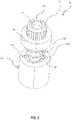
- FIG. 1is a schematic side view of an acousto-optic device, according to the present disclosure.
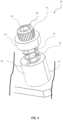
- FIG. 2is a schematic side view of the fastener assembly from the acousto-optic device from FIG. 1 in an uncompressed state without the nut and the chassis.
- FIG. 3is a schematic perspective view of the fastener assembly from the acousto-optic device from FIG. 1 in the uncompressed state without the nut, the base sleeve, and the chassis.
- FIG. 4is a schematic perspective view of the fastener assembly from the acousto-optic device from FIG. 1 in the uncompressed state without the nut and the chassis.
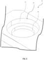
- FIG. 5is a schematic perspective view of the cover and cover passageway from the acousto-optic device from FIG. 1 .
- FIG. 6is a schematic cross-sectional view of the fastener assembly from the acousto-optic device from FIG. 1 in the compressed state.
- FIG. 7is a schematic perspective view of the base sleeve from the acousto-optic device from FIG. 1 .
- FIG. 8is a schematic cross-sectional view of another embodiment of the retainer sleeve from the acousto-optic device from FIG. 1 .
- captive fastenersare used to provide fast removal and reinstallation of the panel cover. Moreover, captive fasteners prevent dislodgement of the fastener from the panel cover during installation thereof.
- Typical captive fastenersare coupled to drilled passageways in the periphery of the panel cover via a cold flow or press process that permanently deforms the drilled passageways. To provide a secure coupling, a number of captive fasteners are used, which cumulatively increases the chance of failure.
- the drilled passagewaycannot support another captive fastener since the adjacent metal portions are damaged.
- the usermay drill out the existing passageway to a greater diameter, and source another different sized captive fastener.
- the chassiscannot support the larger captive fastener and the entire panel cover is replaced (e.g. chassis passageways are fixed in size), which is costly.
- the acousto-optic device 10illustratively includes a chassis 11 and an associated cover 12 to be coupled to the chassis.
- the chassis 11may be part of a mobile platform, such as an aircraft or a land vehicle.
- the acousto-optic device 10comprises an acousto-optic component 13 carried by the chassis 11 , and the cover 12 is configured to shield and protect the acousto-optic component.
- the acousto-optic component 13may alternatively comprise an electronic component.
- the chassis 11may comprise a rack system, a platform interior/housing, or any structure strong enough to carry the acousto-optic component 13 .
- the chassis 11illustratively comprises a chassis passageway 14 therethrough, and the cover 12 has a cover passageway 15 therethrough and aligned with the chassis passageway.
- the cover passageway 15comprises a counterbored cover passageway comprising a first borehole 16 facing outward and away from the chassis 11 having a first diameter, and a second borehole 17 facing the chassis and having a second diameter greater than the first diameter.
- the acousto-optic device 10illustratively includes a fastener assembly 20 for removably securing the cover 12 to the chassis 11 .
- the fastener assembly 20includes a base sleeve 21 comprising an enlarged head 22 , and a tubular body 23 coupled thereto and extending through the cover passageway 15 .
- the tubular body 23has a threaded exterior 24 and defines an axial through passageway 38 .
- the fastener assembly 20illustratively comprises a retainer sleeve 25 having a threaded interior 26 secured to the threaded exterior 24 of the base sleeve 21 to define an anchor member.
- the enlarged head 22illustratively comprises a plurality of tool recesses 37 a - 37 b ( FIG. 7 ) for permitting easy threading of the retainer sleeve 25 onto the base sleeve 21 .
- the retainer sleeve 25includes a plurality of tool recesses 29 a - 29 b.
- the tubular body 23 of the base sleeve 21has a threaded interior 27 defining a thread interior of the anchor member.
- the retainer sleeve 25comprises a reduced diameter passageway 28 and adjacent shelf to abut the tubular body 23 of the base sleeve 21 .
- the fastener assembly 20illustratively includes a fastener 30 comprising an enlarged head 31 , and a shaft 32 extending therefrom.
- the enlarged head 31 of the fastener 30includes a tool recess 39 .
- the shaft 32includes a threaded exterior 33 opposite the enlarged head 31 and to be threaded through the threaded interior (i.e. the threaded interior 27 of the base sleeve 21 ) of the anchor member to capture the fastener 30 to the cover 12 and movable through the chassis passageway 14 for removably securing the cover to the chassis 11 .
- the fastener assembly 20illustratively includes a biasing member 34 coupled between the retainer sleeve 25 and the enlarged head 31 of the fastener 30 .
- the biasing member 34illustratively comprises a coil spring, for example.
- the fastener assembly 20comprises a washer 35 coupled between the enlarged head 31 of the fastener 30 and the biasing member 34 .
- the recess in the washer 35is sized such that, when final torque is applied to the fastener 30 , the biasing member 34 is not in the primary load-path. In the illustrated embodiment, this means that when the washer 35 “bottoms out” on the retainer sleeve 25 , the biasing member is not in its fully compressed state.
- the washer 35illustratively comprises a shroud which covers the biasing member 34 when the fastener assembly 20 is in the compressed state, which provides a barrier to debris from entering the enclosed space.
- the washer 35 and the biasing member 34may be removed for cost reduction purposes.
- the enlarged head 22 of the base sleeve 21is spaced apart from adjacent portions of the cover passageway 15 .
- the fastener assembly 20is floating within the cover passageway 15 .
- the fastener 30comprises a nut 36 secured to the threaded exterior 33 of the shaft 32 on a side of the chassis 11 opposite the cover 12 .
- the nut 36may be omitted when the chassis passageway 14 is threaded, or when the fastener 30 has a self-tapping threaded shaft.
- the fastener assembly 20comprises a metallic material, for example.
- the fastener assembly 20may comprise a polymer material, or any other material with sufficient mechanical strength.
- the cover 12may comprise a metallic material (e.g. sheet metal) or a polymer material, for example.
- Yet another aspectis directed to a method for making a fastener assembly 20 for removably securing a chassis 11 and an associated cover 12 together.
- the chassis 11has a chassis passageway 14 therethrough
- the cover 12has a cover passageway 15 therethrough and aligned with the chassis passageway.
- the methodincludes providing a base sleeve 21 comprising an enlarged head 22 , and a tubular body 23 coupled thereto to extend through the cover passageway 15 , the tubular body having a threaded exterior 24 .
- the methodincludes providing a retainer sleeve 25 having a threaded interior 26 to be secured to the threaded exterior 24 of the base sleeve 21 to define an anchor member, the anchor member having a threaded interior.
- the methodfurther includes providing a fastener 30 comprising an enlarged head 31 , and a shaft 32 extending therefrom.
- the shaft 32has a threaded exterior 33 opposite the enlarged head 31 and to be threaded through the threaded interior (i.e. the threaded interior 27 of the base sleeve 21 ) of the anchor member to capture the fastener 30 to the cover 12 and movable through the chassis passageway 14 for removably securing the cover to the chassis 11 .
- the methodcomprises providing a biasing member 34 to be coupled between the retainer sleeve 25 and the enlarged head 31 of the fastener 30 .
- the methodincludes providing the base sleeve 21 in the cover passageway.
- the methodincludes rotationally locking the base sleeve 21 via the plurality of tool recesses 37 a - 37 b , and threading the retainer sleeve 25 onto the base sleeve.
- the methodincludes passing the fastener 30 through the washer 35 , the biasing member 34 , and the reduced diameter passageway 28 of the retainer sleeve 25 .
- the methodincludes threading the shaft 32 of the fastener 30 through the threaded interior 27 of the base sleeve 21 , which prevents the fastener from backing out during placement of the cover 12 .
- the methodincludes compressing the biasing member 34 from an uncompressed state ( FIGS. 2 - 3 & 4 ) to a compressed stated ( FIGS. 1 & 6 ) and extending the shaft 32 through the chassis passageway for coupling therein.
- this embodimentdiffers from the previous embodiment in that this retainer sleeve 125 illustratively includes a reduced diameter threaded interior 140 aligned with the threaded interior 126 of the retainer sleeve.
- the reduced diameter threaded interior 140defines the threaded interior of the anchor member (i.e. stopping the fastener from backing out), and the threaded interior of the base sleeve would be omitted.
- the fastener assembly 20is coupled to the cover 12 without permanent damage to the cover passageway 15 .
- Thisis in contrast to typical captive fasteners, which permanently deform the cover passageway 15 .
- the fastener assembly 20can tolerate greater variation in the dimensions of the drilled passageways (i.e. looser tolerances on cover passageway placement, making for easier preparation work).
- the fastener assembly 20is readily removable and replaceable, and provides an arbitrary radial float (float is driven by the hole size in the parent material and can be tailored for individual applications).
- the fastener assembly 20may provide for edge proximity since the parent material isn't stressed during installation, and this system can be installed much closer to edges or bends than typical approaches.
Landscapes
- Engineering & Computer Science (AREA)
- General Engineering & Computer Science (AREA)
- Mechanical Engineering (AREA)
- Physics & Mathematics (AREA)
- Nonlinear Science (AREA)
- General Physics & Mathematics (AREA)
- Optics & Photonics (AREA)
- Dowels (AREA)
Abstract
Description
Claims (20)
Priority Applications (1)
| Application Number | Priority Date | Filing Date | Title |
|---|---|---|---|
| US16/789,571US11566647B2 (en) | 2020-02-13 | 2020-02-13 | Acousto-optic device with captive fastener and related assemblies and methods |
Applications Claiming Priority (1)
| Application Number | Priority Date | Filing Date | Title |
|---|---|---|---|
| US16/789,571US11566647B2 (en) | 2020-02-13 | 2020-02-13 | Acousto-optic device with captive fastener and related assemblies and methods |
Publications (2)
| Publication Number | Publication Date |
|---|---|
| US20210254645A1 US20210254645A1 (en) | 2021-08-19 |
| US11566647B2true US11566647B2 (en) | 2023-01-31 |
Family
ID=77272641
Family Applications (1)
| Application Number | Title | Priority Date | Filing Date |
|---|---|---|---|
| US16/789,571Active2040-11-21US11566647B2 (en) | 2020-02-13 | 2020-02-13 | Acousto-optic device with captive fastener and related assemblies and methods |
Country Status (1)
| Country | Link |
|---|---|
| US (1) | US11566647B2 (en) |
Families Citing this family (2)
| Publication number | Priority date | Publication date | Assignee | Title |
|---|---|---|---|---|
| US11519299B2 (en) | 2017-12-22 | 2022-12-06 | Hamilton Sundstrand Corporation | Sliding mount |
| US11603879B2 (en)* | 2020-05-22 | 2023-03-14 | Hamilton Sundstrand Corporation | Captive fastener systems |
Citations (26)
| Publication number | Priority date | Publication date | Assignee | Title |
|---|---|---|---|---|
| US2831520A (en)* | 1954-07-20 | 1958-04-22 | Northrop Aircraft Inc | Telescoping captive screw holder with stop means for screw |
| US3180389A (en) | 1962-03-02 | 1965-04-27 | Frank Charles | Fastener-captive front panel |
| US3209806A (en) | 1963-11-12 | 1965-10-05 | Automatic Elect Lab | Floatingly mounted captive thumbscrew fastener |
| US3245450A (en)* | 1962-06-29 | 1966-04-12 | Deutsch Fastener Corp | Self-retracting screw |
| US3346032A (en) | 1966-01-18 | 1967-10-10 | Deutsch Fastener Corp | Floating captive screw |
| US3415302A (en) | 1967-10-04 | 1968-12-10 | Josiah D. Beck | Captive fastener assembly |
| US3831137A (en)* | 1972-04-14 | 1974-08-20 | Us Navy | Acousto-optic underwater detector |
| US4069855A (en) | 1977-03-04 | 1978-01-24 | Tridair Industries | Captive panel fastener |
| US4191236A (en) | 1977-08-09 | 1980-03-04 | Avibank Mfg., Inc. | Captive panel fastener assembly |
| US4387497A (en)* | 1980-11-07 | 1983-06-14 | Bulent Gulistan | Captive screw assembly method and product |
| US4396327A (en)* | 1979-10-17 | 1983-08-02 | Erno Raumfahrttechnik Gmbh | Screw capture |
| US4464091A (en) | 1981-01-12 | 1984-08-07 | Deutsch Fastener Corp. | Captive fastener |
| US4553890A (en) | 1982-06-14 | 1985-11-19 | Bulent Gulistan | Captive panel screw |
| US4594040A (en) | 1983-08-29 | 1986-06-10 | Deutsch Fastener Corp. | Panel fastener |
| US4609314A (en) | 1984-05-21 | 1986-09-02 | Norco, Inc. | Panel fastener |
| US4692075A (en) | 1986-05-02 | 1987-09-08 | Norco,Inc. | Panel fastener |
| US5206869A (en)* | 1990-11-13 | 1993-04-27 | Escher-Grad Incorporated | Method and device for generating high quality laser beam from laser diodes |
| US5336028A (en)* | 1993-04-13 | 1994-08-09 | Vsi Corporation | Captive screw assembly |
| US5338139A (en)* | 1993-10-20 | 1994-08-16 | Penn Engineering & Manufacturing Corp. | Shrouded captive screw |
| US20100315698A1 (en)* | 2007-04-10 | 2010-12-16 | Dixon George J | Modular ring resonator |
| US20130014376A1 (en) | 2009-09-09 | 2013-01-17 | Igor Komsitsky | Panel fastener, panel assembly and methods of assembly and installation |
| US20140096363A1 (en) | 2012-10-08 | 2014-04-10 | Tejas Networks Limited | Captive fastener assembly |
| US8794889B2 (en) | 2000-03-10 | 2014-08-05 | Southco, Inc. | Floating captive screw |
| US8827614B2 (en) | 2012-08-30 | 2014-09-09 | Hanwit Precision Industries Ltd. | Floating fastener allowing a high pre-positioning tolerance |
| US8950991B2 (en) | 2010-10-13 | 2015-02-10 | Primordial Soup, Llc | Screw captivator |
| US9328753B2 (en)* | 2010-10-13 | 2016-05-03 | Primordial Soup, Llc | Screw captivator |
- 2020
- 2020-02-13USUS16/789,571patent/US11566647B2/enactiveActive
Patent Citations (27)
| Publication number | Priority date | Publication date | Assignee | Title |
|---|---|---|---|---|
| US2831520A (en)* | 1954-07-20 | 1958-04-22 | Northrop Aircraft Inc | Telescoping captive screw holder with stop means for screw |
| US3180389A (en) | 1962-03-02 | 1965-04-27 | Frank Charles | Fastener-captive front panel |
| US3245450A (en)* | 1962-06-29 | 1966-04-12 | Deutsch Fastener Corp | Self-retracting screw |
| US3209806A (en) | 1963-11-12 | 1965-10-05 | Automatic Elect Lab | Floatingly mounted captive thumbscrew fastener |
| US3346032A (en) | 1966-01-18 | 1967-10-10 | Deutsch Fastener Corp | Floating captive screw |
| US3415302A (en) | 1967-10-04 | 1968-12-10 | Josiah D. Beck | Captive fastener assembly |
| US3831137A (en)* | 1972-04-14 | 1974-08-20 | Us Navy | Acousto-optic underwater detector |
| US4069855A (en) | 1977-03-04 | 1978-01-24 | Tridair Industries | Captive panel fastener |
| US4191236A (en) | 1977-08-09 | 1980-03-04 | Avibank Mfg., Inc. | Captive panel fastener assembly |
| US4396327A (en)* | 1979-10-17 | 1983-08-02 | Erno Raumfahrttechnik Gmbh | Screw capture |
| US4387497A (en)* | 1980-11-07 | 1983-06-14 | Bulent Gulistan | Captive screw assembly method and product |
| US4464091A (en) | 1981-01-12 | 1984-08-07 | Deutsch Fastener Corp. | Captive fastener |
| US4553890A (en) | 1982-06-14 | 1985-11-19 | Bulent Gulistan | Captive panel screw |
| US4594040A (en) | 1983-08-29 | 1986-06-10 | Deutsch Fastener Corp. | Panel fastener |
| US4609314A (en) | 1984-05-21 | 1986-09-02 | Norco, Inc. | Panel fastener |
| US4692075A (en) | 1986-05-02 | 1987-09-08 | Norco,Inc. | Panel fastener |
| US5206869A (en)* | 1990-11-13 | 1993-04-27 | Escher-Grad Incorporated | Method and device for generating high quality laser beam from laser diodes |
| US5336028A (en)* | 1993-04-13 | 1994-08-09 | Vsi Corporation | Captive screw assembly |
| US5338139A (en)* | 1993-10-20 | 1994-08-16 | Penn Engineering & Manufacturing Corp. | Shrouded captive screw |
| US8794889B2 (en) | 2000-03-10 | 2014-08-05 | Southco, Inc. | Floating captive screw |
| US20100315698A1 (en)* | 2007-04-10 | 2010-12-16 | Dixon George J | Modular ring resonator |
| US20130014376A1 (en) | 2009-09-09 | 2013-01-17 | Igor Komsitsky | Panel fastener, panel assembly and methods of assembly and installation |
| US9033632B2 (en) | 2009-09-09 | 2015-05-19 | The Monadnock Company | Panel fastener, panel assembly and methods of assembly and installation |
| US8950991B2 (en) | 2010-10-13 | 2015-02-10 | Primordial Soup, Llc | Screw captivator |
| US9328753B2 (en)* | 2010-10-13 | 2016-05-03 | Primordial Soup, Llc | Screw captivator |
| US8827614B2 (en) | 2012-08-30 | 2014-09-09 | Hanwit Precision Industries Ltd. | Floating fastener allowing a high pre-positioning tolerance |
| US20140096363A1 (en) | 2012-10-08 | 2014-04-10 | Tejas Networks Limited | Captive fastener assembly |
Also Published As
| Publication number | Publication date |
|---|---|
| US20210254645A1 (en) | 2021-08-19 |
Similar Documents
| Publication | Publication Date | Title |
|---|---|---|
| US8206071B1 (en) | Cabinet anchor bolt assembly | |
| US11566647B2 (en) | Acousto-optic device with captive fastener and related assemblies and methods | |
| RU2589667C2 (en) | Bolt for blind attachment | |
| EP2951095B1 (en) | Sleeved fastener assembly | |
| US10012149B2 (en) | Two degree-of-constraint semi-fusible gearbox mounting link | |
| US10975904B2 (en) | Clearance floating anchor nut | |
| US10398053B2 (en) | Equipment clamping assembly having horizontal and vertical clamps for use in rugged and other environments | |
| US20180177066A1 (en) | Equipment clamping assembly using clamps and friction to secure equipment for use in rugged and other environments | |
| EP3010742B1 (en) | Mounting structure for an engine mount and method | |
| EP0971572A1 (en) | An assembly comprising two components and a mechanism for fastening them together | |
| US6736578B2 (en) | Front mounted retaining mechanism | |
| US20170204960A1 (en) | Transmission case | |
| US11462854B2 (en) | Electrical connector with a mounting flange and method of assembling same | |
| EP2724035B1 (en) | Captive fastener assembly and machine using same | |
| USH1981H1 (en) | Bearing stress-free locking device | |
| US20250122900A1 (en) | Nut retaining device and related methods | |
| CN107546497B (en) | The method of grounding connection is provided between component and car body guide rail | |
| US12279695B2 (en) | Self aligning wall rail for enclosure wall mounting | |
| WO2016057010A1 (en) | Casing component with bayonet clamping ring to connect to a combustor in a gas turbine | |
| US20100172713A1 (en) | Self locking floating fastener | |
| EP1604123B1 (en) | A fastening device | |
| EP4074988B1 (en) | Connection system and method of connecting | |
| US6074122A (en) | Cone drive power train connection | |
| US20220307541A1 (en) | Carrier For Mounting Of Panel Inserts | |
| US11147178B2 (en) | Pre-strain unit for a T-bolt |
Legal Events
| Date | Code | Title | Description |
|---|---|---|---|
| FEPP | Fee payment procedure | Free format text:ENTITY STATUS SET TO UNDISCOUNTED (ORIGINAL EVENT CODE: BIG.); ENTITY STATUS OF PATENT OWNER: LARGE ENTITY | |
| AS | Assignment | Owner name:EAGLE TECHNOLOGY, LLC, FLORIDA Free format text:ASSIGNMENT OF ASSIGNORS INTEREST;ASSIGNORS:COREY, CHRISTOPHER A.;BRAUN, CARRIGAN L.;REEL/FRAME:051820/0828 Effective date:20200210 | |
| STPP | Information on status: patent application and granting procedure in general | Free format text:DOCKETED NEW CASE - READY FOR EXAMINATION | |
| STPP | Information on status: patent application and granting procedure in general | Free format text:NON FINAL ACTION MAILED | |
| STPP | Information on status: patent application and granting procedure in general | Free format text:RESPONSE TO NON-FINAL OFFICE ACTION ENTERED AND FORWARDED TO EXAMINER | |
| STPP | Information on status: patent application and granting procedure in general | Free format text:FINAL REJECTION MAILED | |
| STPP | Information on status: patent application and granting procedure in general | Free format text:DOCKETED NEW CASE - READY FOR EXAMINATION | |
| STPP | Information on status: patent application and granting procedure in general | Free format text:NOTICE OF ALLOWANCE MAILED -- APPLICATION RECEIVED IN OFFICE OF PUBLICATIONS | |
| STPP | Information on status: patent application and granting procedure in general | Free format text:NOTICE OF ALLOWANCE MAILED -- APPLICATION RECEIVED IN OFFICE OF PUBLICATIONS | |
| STPP | Information on status: patent application and granting procedure in general | Free format text:PUBLICATIONS -- ISSUE FEE PAYMENT VERIFIED | |
| STCF | Information on status: patent grant | Free format text:PATENTED CASE |