US11565457B2 - Electrical heating mold - Google Patents
Electrical heating moldDownload PDFInfo
- Publication number
- US11565457B2 US11565457B2US17/421,448US202017421448AUS11565457B2US 11565457 B2US11565457 B2US 11565457B2US 202017421448 AUS202017421448 AUS 202017421448AUS 11565457 B2US11565457 B2US 11565457B2
- Authority
- US
- United States
- Prior art keywords
- element group
- annular
- resistor element
- heating resistor
- semi
- Prior art date
- Legal status (The legal status is an assumption and is not a legal conclusion. Google has not performed a legal analysis and makes no representation as to the accuracy of the status listed.)
- Active
Links
- 238000010438heat treatmentMethods0.000titleclaimsabstractdescription167
- 238000005452bendingMethods0.000claimsdescription3
- 230000000694effectsEffects0.000abstractdescription3
- 238000007664blowingMethods0.000description6
- 239000012530fluidSubstances0.000description4
- 238000004519manufacturing processMethods0.000description3
- 239000011111cardboardSubstances0.000description1
- 239000000463materialSubstances0.000description1
- 239000007769metal materialSubstances0.000description1
- 238000000034methodMethods0.000description1
- 238000000465mouldingMethods0.000description1
- XLYOFNOQVPJJNP-UHFFFAOYSA-NwaterSubstancesOXLYOFNOQVPJJNP-UHFFFAOYSA-N0.000description1
Images


Classifications
- B—PERFORMING OPERATIONS; TRANSPORTING
- B29—WORKING OF PLASTICS; WORKING OF SUBSTANCES IN A PLASTIC STATE IN GENERAL
- B29C—SHAPING OR JOINING OF PLASTICS; SHAPING OF MATERIAL IN A PLASTIC STATE, NOT OTHERWISE PROVIDED FOR; AFTER-TREATMENT OF THE SHAPED PRODUCTS, e.g. REPAIRING
- B29C49/00—Blow-moulding, i.e. blowing a preform or parison to a desired shape within a mould; Apparatus therefor
- B29C49/42—Component parts, details or accessories; Auxiliary operations
- B29C49/48—Moulds
- B29C49/4823—Moulds with incorporated heating or cooling means
- B29C2049/4838—Moulds with incorporated heating or cooling means for heating moulds or mould parts
- B29C2049/4846—Moulds with incorporated heating or cooling means for heating moulds or mould parts in different areas of the mould at different temperatures, e.g. neck, shoulder or bottom
- B—PERFORMING OPERATIONS; TRANSPORTING
- B29—WORKING OF PLASTICS; WORKING OF SUBSTANCES IN A PLASTIC STATE IN GENERAL
- B29C—SHAPING OR JOINING OF PLASTICS; SHAPING OF MATERIAL IN A PLASTIC STATE, NOT OTHERWISE PROVIDED FOR; AFTER-TREATMENT OF THE SHAPED PRODUCTS, e.g. REPAIRING
- B29C49/00—Blow-moulding, i.e. blowing a preform or parison to a desired shape within a mould; Apparatus therefor
- B29C49/42—Component parts, details or accessories; Auxiliary operations
- B29C49/48—Moulds
- B29C2049/4879—Moulds characterised by mould configurations
- B29C2049/4889—Mould halves consisting of an independent neck, main and bottom part
- B—PERFORMING OPERATIONS; TRANSPORTING
- B29—WORKING OF PLASTICS; WORKING OF SUBSTANCES IN A PLASTIC STATE IN GENERAL
- B29C—SHAPING OR JOINING OF PLASTICS; SHAPING OF MATERIAL IN A PLASTIC STATE, NOT OTHERWISE PROVIDED FOR; AFTER-TREATMENT OF THE SHAPED PRODUCTS, e.g. REPAIRING
- B29C2949/00—Indexing scheme relating to blow-moulding
- B29C2949/07—Preforms or parisons characterised by their configuration
- B29C2949/0715—Preforms or parisons characterised by their configuration the preform having one end closed
- B—PERFORMING OPERATIONS; TRANSPORTING
- B29—WORKING OF PLASTICS; WORKING OF SUBSTANCES IN A PLASTIC STATE IN GENERAL
- B29C—SHAPING OR JOINING OF PLASTICS; SHAPING OF MATERIAL IN A PLASTIC STATE, NOT OTHERWISE PROVIDED FOR; AFTER-TREATMENT OF THE SHAPED PRODUCTS, e.g. REPAIRING
- B29C49/00—Blow-moulding, i.e. blowing a preform or parison to a desired shape within a mould; Apparatus therefor
- B29C49/02—Combined blow-moulding and manufacture of the preform or the parison
- B29C49/06—Injection blow-moulding
- B—PERFORMING OPERATIONS; TRANSPORTING
- B29—WORKING OF PLASTICS; WORKING OF SUBSTANCES IN A PLASTIC STATE IN GENERAL
- B29L—INDEXING SCHEME ASSOCIATED WITH SUBCLASS B29C, RELATING TO PARTICULAR ARTICLES
- B29L2031/00—Other particular articles
- B29L2031/712—Containers; Packaging elements or accessories, Packages
- B29L2031/7158—Bottles
Definitions
- the present disclosurerelates to the field of bottle blowing manufacture, in particular, a bottle blowing mold having an electrical heating device.
- a bottle parisonneeds to be placed in an electrical heating mold so as to be blown into a container bottle, and heating is required during the blowing process so that the bottle parison can be better stretched to form the container bottle.
- preheating fluidsuch as water or oil
- a relatively large heat exchange between the cavity wall and the container bottleis required, more preheating fluid is required and thus the preheating fluid needs to have a large reserve.
- the preheating fluidneeds to flow to transfer heat, a flow channel needs to be provided in the mold, and the structure of the flow channel is complex, thus increasing the manufacturing difficulty and manufacturing cost of the mold.
- European Patent EP1753597describes that the resistor is arranged at an interface between a mold casing and a bottom mold. During heating, the heat is dissipated from bottom to top, resulting in poor heating effect of the bottom of the container bottle, which affects the molding quality.
- the resistorhas a shape of a coil. Setting the resistor on the bottom mold requires complex processing of the bottom mold, and the processing is difficult and high in cost.
- the present disclosureaims to provide an electrical heating mold with good heating effect, a low processing cost and a simple structure.
- the electrical heating moldprovided by the present disclosure includes a mold casing and an electrical heating device disposed in the mold casing.
- the electrical heating deviceincludes an upper annular heating resistor element group configured to perform heating around a bottleneck, a middle annular vertical-inserted columnar heating resistor element group configured to perform heating around a bottle body, and a lower annular heating resistor element group configured to perform heating around a bottle bottom.
- the electrical heating deviceincludes the upper annular heating resistor element group configured to perform heating around the bottleneck, the middle annular vertical-inserted columnar heating resistor element group configured to perform heating around the bottle body, and the lower annular heating resistor element group configured to perform heating around the bottle bottom. Since the bottleneck has a small diameter, when the middle annular vertical-inserted columnar heating resistor element group performs heating on the bottle body, the heat, generated by the middle annular vertical-inserted columnar heating resistor element group, radiated to the bottleneck is reduced, so that a heating temperature at the bottleneck is insufficient.
- the upper annular heating resistor element groupis arranged at the bottleneck to perform heating around the bottleneck (a surrounding diameter of the upper annular heating resistor element group may be adjusted according to diameters of bottlenecks of different container bottles). In this manner, the heating temperature at the bottleneck can be ensured and the heating temperature at the bottleneck is more uniform, thus ensuring the blowing quality at the bottleneck.
- the bottom moldis made of metal material, and the heat is dissipated from bottom to top when the middle annular vertical-inserted columnar heating resistor element group performs heating, the heat energy at the bottle bottom is quickly dissipated.
- the lower annular heating resistor element groupis arranged to perform heating around the bottle bottom so as to ensure a heating temperature at the bottle bottom. In this manner, the heating temperature at the bottle bottom is uniform, and the blowing quality at the bottle bottom is guaranteed.
- Heating resistor element groups with different structuresare provided for different positions of the container bottle so that optimal usage of heat energy can be achieved, and meanwhile the structure of the mold is simplified and the processing cost is saved.
- surrounding diameters and height positions of the upper annular heating resistor element group and the lower annular heating resistor element group, and a length of the middle vertical-inserted columnar heating resistor element groupmay further be adjusted so that the electrical heating mold adapts to container bottles of more shapes and has a wider application range.
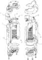
- FIG. 1is a structure view according to the present disclosure
- FIG. 2is an exploded structure view according to the present disclosure
- FIG. 3is a view in a direction A of FIG. 1 (a flange of a bottleneck is removed);
- FIG. 4is a view in a direction B of FIG. 1 (a bottom mold, a bottom mold card board, a thickness plate, and a lower cover plate are removed);
- FIGS. 5 and 6are schematic views of an electrical heating device
- FIG. 7is a top view of FIG. 1 ;
- FIG. 8is a cross-sectional view take along a line C-C of FIG. 7 .
- an electrical heating moldincludes a mold casing 1 and an electrical heating device disposed in the mold casing 1 .
- the electrical heating deviceincludes an upper annular heating resistor element group 2 configured to perform heating around a bottleneck, a middle annular vertical-inserted columnar heating resistor element group 3 configured to perform heating around a bottle body, and a lower annular heating resistor element group 4 configured to perform heating around a bottle bottom.
- the mold casingincludes a left mold casing 11 and a right mold casing 12 .
- the upper annular heating resistor element group 2includes a left semi-annular upper heating resistor element group 21 and a right semi-annular upper heating resistor element group 22 which are disposed on the left mold casing 11 and the right mold casing 12 , respectively.
- the middle annular vertical-inserted columnar heating resistor element group 3includes a left semi-annular middle vertical-inserted columnar heating resistor element group and a right semi-annular middle vertical-inserted columnar heating resistor element group which are disposed on the left mold casing 11 and the right mold casing 12 , respectively.
- the lower annular heating resistor element group 4includes a left semi-annular lower heating resistor element group and a right semi-annular lower heating resistor element group which are disposed on the left mold casing 11 and the right mold casing 12 , respectively.
- An upper end surface of the left mold casing 11 and an upper end surface of the right mold casing 12are provided with a left upper cover plate and a right upper cover plate, respectively, and the left semi-annular upper heating resistor element group 21 and the right semi-annular upper heating resistor element group 22 are disposed on the left upper cover plate and the right upper cover plate, respectively.
- the left semi-annular lower heating resistor element group and the right semi-annular lower heating resistor element groupare disposed on a lower end surface of the left mold casing 11 and a lower end surface of the right mold casing 12 , respectively.
- the left semi-annular middle vertical-inserted columnar heating resistor element group and the right semi-annular middle vertical-inserted columnar heating resistor element groupare inserted into the left mold casing 11 from the upper end surface of the left mold casing 11 and the right mold casing 12 from the upper end surface of the right mold casing 12 , respectively.
- the left semi-annular upper heating resistor element group 21 , the left semi-annular middle vertical-inserted columnar heating resistor element group, and the left semi-annular lower heating resistor element groupare connected in series through a first wire.
- the right semi-annular upper heating resistor element group 22 , the right semi-annular middle vertical-inserted columnar heating resistor element group, and the right semi-annular lower heating resistor element groupare connected in series through a second wire. Both the first wire and the second wire extend into a junction box 8 , and the junction box 8 is disposed on the left upper cover plate or the right upper cover plate.
- the left semi-annular upper heating resistor element group 21 , the right semi-annular upper heating resistor element group 22 , the left semi-annular lower heating resistor element group, and the right semi-annular lower heating resistor element groupeach are formed by a plurality of horizontally arranged columnar heating rods 5 which are connected with each other and distributed at intervals in a semi-annular arrangement.
- the left semi-annular upper heating resistor element group 21 , the right semi-annular upper heating resistor element group 22 , the left semi-annular lower heating resistor element group, and the right semi-annular lower heating resistor element groupeach are formed by an electrical heating sheet 6 bending in a semi-annular shape.
- the left semi-annular middle vertical-inserted columnar heating resistor element group and the right semi-annular middle vertical-inserted columnar heating resistor element groupeach include a plurality of vertically arranged heating rods 7 which are distributed at intervals in a semi-annular arrangement, and top ends of all the heating rods 7 are connected in series.
- Materials or resistance values of the upper annular heating resistor element group, the middle annular vertical-inserted columnar heating resistor element group, and the lower annular heating resistor element groupmay be the same or different.
Landscapes
- Engineering & Computer Science (AREA)
- Manufacturing & Machinery (AREA)
- Mechanical Engineering (AREA)
- Resistance Heating (AREA)
- Moulds For Moulding Plastics Or The Like (AREA)
- Blow-Moulding Or Thermoforming Of Plastics Or The Like (AREA)
- Cookers (AREA)
Abstract
Description
Claims (4)
Applications Claiming Priority (3)
| Application Number | Priority Date | Filing Date | Title |
|---|---|---|---|
| CN201910536929.9ACN110126240B (en) | 2019-06-20 | 2019-06-20 | Electric heating die |
| CN201910536929.9 | 2019-06-20 | ||
| PCT/CN2020/081550WO2020253303A1 (en) | 2019-06-20 | 2020-03-27 | Electrical heating mould |
Publications (2)
| Publication Number | Publication Date |
|---|---|
| US20220080648A1 US20220080648A1 (en) | 2022-03-17 |
| US11565457B2true US11565457B2 (en) | 2023-01-31 |
Family
ID=67578781
Family Applications (1)
| Application Number | Title | Priority Date | Filing Date |
|---|---|---|---|
| US17/421,448ActiveUS11565457B2 (en) | 2019-06-20 | 2020-03-27 | Electrical heating mold |
Country Status (5)
| Country | Link |
|---|---|
| US (1) | US11565457B2 (en) |
| EP (1) | EP3892442B1 (en) |
| JP (1) | JP7177942B2 (en) |
| CN (1) | CN110126240B (en) |
| WO (1) | WO2020253303A1 (en) |
Families Citing this family (1)
| Publication number | Priority date | Publication date | Assignee | Title |
|---|---|---|---|---|
| CN110126240B (en)* | 2019-06-20 | 2024-04-19 | 广州达意隆包装机械股份有限公司 | Electric heating die |
Citations (14)
| Publication number | Priority date | Publication date | Assignee | Title |
|---|---|---|---|---|
| GB1480647A (en)* | 1973-08-01 | 1977-07-20 | Unilever Ltd | Process for producing hollow articles by injection and blow moulding |
| US4233022A (en) | 1978-07-10 | 1980-11-11 | Owens-Illinois, Inc. | Apparatus for forming heat treated blown thermoplastic articles |
| JPH0342632U (en) | 1989-08-30 | 1991-04-23 | ||
| CN2111179U (en) | 1992-01-31 | 1992-07-29 | 张金山 | Plastic parison heating device |
| US5411698A (en) | 1992-09-22 | 1995-05-02 | Pepsico., Inc. | Process and apparatus for blow mold annealing and subsequently heat treating thermoplastic articles |
| EP1753597B1 (en) | 2003-09-17 | 2008-05-14 | S.I.P.A. Societa Industrializzazione Progettazione E Automazione - S.P.A. | Heated blow mould for thermostabilizing treatment |
| US20080220114A1 (en) | 2007-03-05 | 2008-09-11 | R & D Tool & Engineering Co. | Method and apparatus for conditioning preforms in an injection stretch blow mold machine |
| CN202862466U (en) | 2012-10-29 | 2013-04-10 | 梁添炯 | A high-efficiency electric heating coil |
| EP2307185B1 (en) | 2008-08-04 | 2014-08-06 | KHS Corpoplast GmbH | Method and apparatus for blow moulding of containers |
| US20140377394A1 (en)* | 2011-12-23 | 2014-12-25 | Sidel Participations | Mould for forming containers, equipped with an electric heating system comprising a set of distinct resistive elements |
| JP2017124571A (en) | 2016-01-15 | 2017-07-20 | 東洋製罐株式会社 | Blow molding die device |
| US20180104885A1 (en)* | 2015-04-15 | 2018-04-19 | Sidel Participations | Unit for moulding containers provided with an offset radiator and an integrated temperature probe |
| CN109397668A (en) | 2018-11-30 | 2019-03-01 | 江苏辉河包装机械有限公司 | A kind of bottle blowing mould |
| CN208867548U (en) | 2018-08-30 | 2019-05-17 | 佛山市瑞达佰邦密封科技有限公司 | A kind of note blows integrated blow mold |
Family Cites Families (17)
| Publication number | Priority date | Publication date | Assignee | Title |
|---|---|---|---|---|
| DE2545130C3 (en)* | 1975-10-08 | 1980-06-26 | Gildemeister Corpoplast Gmbh, 2000 Hamburg | Apparatus for blow molding a container |
| JPS59103832A (en)* | 1983-10-28 | 1984-06-15 | 東洋紡績株式会社 | Polyester vessel |
| CN2318026Y (en)* | 1997-12-03 | 1999-05-12 | 刘俊松 | Large container injecting, drawing and blowing two-step blow moulding machine |
| JP2006297676A (en)* | 2005-04-18 | 2006-11-02 | Nok Corp | Method and apparatus for manufacturing thermoplastic elastomer molded product |
| CN101125461A (en)* | 2006-08-15 | 2008-02-20 | 郭连生 | Improved heat-resisting PET bottle blowing technology and bottle blowing machine |
| JP5190675B2 (en)* | 2008-03-28 | 2013-04-24 | 大日本印刷株式会社 | Heating bottle manufacturing method, bottle product manufacturing method, and heating bottle |
| JP5794567B2 (en)* | 2010-07-27 | 2015-10-14 | 日精エー・エス・ビー機械株式会社 | Heat forming equipment for heat-resistant containers |
| IT1402342B1 (en)* | 2010-10-12 | 2013-08-30 | Sipa Progettazione Automaz | PREFORM HEATING DEVICE IN THERMOPLASTIC MATERIAL. |
| JP5783180B2 (en)* | 2010-10-25 | 2015-09-24 | 日精エー・エス・ビー機械株式会社 | Manufacturing method of hollow container |
| CN102615811A (en)* | 2012-03-31 | 2012-08-01 | 上海凌力特殊钢发展有限公司 | Decomposing device for rotary type hot-filling bottle blowing mold cavity |
| FR2994880B1 (en)* | 2012-08-28 | 2014-08-29 | Sidel Participations | "METHOD FOR COOLING A MOLD BY CIRCULATING A HEAT PUMP FLUID IN CONTACT WITH ITS EXTERNAL SIDE" |
| CN103112137B (en)* | 2013-02-28 | 2015-09-16 | 山东大学 | A kind of electrical heating rapid thermal circulation injection mould |
| CN204622517U (en)* | 2015-02-06 | 2015-09-09 | 滁州市杰伦特模具塑胶有限公司 | A kind of change mould temperature automobile component injection mold |
| CN105058730B (en)* | 2015-09-17 | 2017-09-01 | 青岛海信模具有限公司 | It is a kind of to heat injection mold with type |
| JP6911380B2 (en)* | 2017-02-24 | 2021-07-28 | 東洋製罐株式会社 | Manufacturing method of synthetic resin container and blow molding mold |
| CN210336840U (en)* | 2019-06-20 | 2020-04-17 | 广州达意隆包装机械股份有限公司 | Electric heating mould |
| CN110126240B (en)* | 2019-06-20 | 2024-04-19 | 广州达意隆包装机械股份有限公司 | Electric heating die |
- 2019
- 2019-06-20CNCN201910536929.9Apatent/CN110126240B/enactiveActive
- 2020
- 2020-03-27EPEP20826431.7Apatent/EP3892442B1/enactiveActive
- 2020-03-27JPJP2021541709Apatent/JP7177942B2/enactiveActive
- 2020-03-27USUS17/421,448patent/US11565457B2/enactiveActive
- 2020-03-27WOPCT/CN2020/081550patent/WO2020253303A1/ennot_activeCeased
Patent Citations (15)
| Publication number | Priority date | Publication date | Assignee | Title |
|---|---|---|---|---|
| GB1480647A (en)* | 1973-08-01 | 1977-07-20 | Unilever Ltd | Process for producing hollow articles by injection and blow moulding |
| US4233022A (en) | 1978-07-10 | 1980-11-11 | Owens-Illinois, Inc. | Apparatus for forming heat treated blown thermoplastic articles |
| JPH0342632U (en) | 1989-08-30 | 1991-04-23 | ||
| CN2111179U (en) | 1992-01-31 | 1992-07-29 | 张金山 | Plastic parison heating device |
| US5411698A (en) | 1992-09-22 | 1995-05-02 | Pepsico., Inc. | Process and apparatus for blow mold annealing and subsequently heat treating thermoplastic articles |
| US7775786B2 (en)* | 2003-09-17 | 2010-08-17 | S, I.P.A. Societa Industrializzione Progettazione e Automazione S.p.A. | Heated blow mould for thermostabilizing treatment |
| EP1753597B1 (en) | 2003-09-17 | 2008-05-14 | S.I.P.A. Societa Industrializzazione Progettazione E Automazione - S.P.A. | Heated blow mould for thermostabilizing treatment |
| US20080220114A1 (en) | 2007-03-05 | 2008-09-11 | R & D Tool & Engineering Co. | Method and apparatus for conditioning preforms in an injection stretch blow mold machine |
| EP2307185B1 (en) | 2008-08-04 | 2014-08-06 | KHS Corpoplast GmbH | Method and apparatus for blow moulding of containers |
| US20140377394A1 (en)* | 2011-12-23 | 2014-12-25 | Sidel Participations | Mould for forming containers, equipped with an electric heating system comprising a set of distinct resistive elements |
| CN202862466U (en) | 2012-10-29 | 2013-04-10 | 梁添炯 | A high-efficiency electric heating coil |
| US20180104885A1 (en)* | 2015-04-15 | 2018-04-19 | Sidel Participations | Unit for moulding containers provided with an offset radiator and an integrated temperature probe |
| JP2017124571A (en) | 2016-01-15 | 2017-07-20 | 東洋製罐株式会社 | Blow molding die device |
| CN208867548U (en) | 2018-08-30 | 2019-05-17 | 佛山市瑞达佰邦密封科技有限公司 | A kind of note blows integrated blow mold |
| CN109397668A (en) | 2018-11-30 | 2019-03-01 | 江苏辉河包装机械有限公司 | A kind of bottle blowing mould |
Non-Patent Citations (3)
| Title |
|---|
| Extended European Search Report in related EP20826431.7 dated Jun. 27, 2022. |
| International Search Report of PCT/CN2020/081550 dated May 9, 2020. |
| Office Action in related JP2021-541709 dated Jun. 29, 2022. |
Also Published As
| Publication number | Publication date |
|---|---|
| CN110126240A (en) | 2019-08-16 |
| JP7177942B2 (en) | 2022-11-24 |
| CN110126240B (en) | 2024-04-19 |
| EP3892442B1 (en) | 2025-04-23 |
| EP3892442A1 (en) | 2021-10-13 |
| US20220080648A1 (en) | 2022-03-17 |
| WO2020253303A1 (en) | 2020-12-24 |
| EP3892442A4 (en) | 2022-07-27 |
| JP2022517279A (en) | 2022-03-07 |
| EP3892442C0 (en) | 2025-04-23 |
Similar Documents
| Publication | Publication Date | Title |
|---|---|---|
| US11565457B2 (en) | Electrical heating mold | |
| CN211770914U (en) | Glass bottle forming die | |
| CN1852802B (en) | Heated blow mould for thermostabilizing treatment | |
| CN210336840U (en) | Electric heating mould | |
| CN213006507U (en) | Bottle preform heating device and bottle blowing equipment | |
| CN216377901U (en) | Glass bottle molding | |
| CN109434082A (en) | A kind of cooling device for automobile die | |
| CN112848226B (en) | Auxiliary accelerated cooling equipment for manufacturing plastic bottle blank | |
| CN205556449U (en) | Glass bottle moulded die of single droplet ranks machine | |
| CN206886944U (en) | A kind of shaping mould bottom coohng device of numerical control bottle-making machine production | |
| CN213860669U (en) | Preform injection temperature control device for bottle and barrel container | |
| CN202482198U (en) | Mould for manufacturing glass container | |
| CN207327568U (en) | A kind of general-using type plastics embryonic tube | |
| CN202519145U (en) | Mold used for making glass container | |
| CN208292849U (en) | A kind of 3D glass self-heating bending mould | |
| CN214088263U (en) | Primary mould for producing glass bottle | |
| CN205909579U (en) | Device at bottom of cooling bottle of numerical control bottle -making machine production | |
| CN209259922U (en) | A kind of processing of square vase mold is with silently | |
| CN207451921U (en) | A kind of glass feeding bottle song body is molded module | |
| CN206799420U (en) | A kind of profiling applied to digital control type bottle-making machine cools down frock | |
| CN209759285U (en) | cooling blowing head applied to production of glass bottle making machine | |
| CN109160715A (en) | Carboy pressuring-blowing process mould | |
| CN217803258U (en) | Pretreatment temperature adjusting device before blow molding of integrated plastic barrel type blank | |
| CN206983157U (en) | It is a kind of to heat the plastic mould for pouring mouth | |
| CN221717815U (en) | A cooling tower in a film blowing machine with temperature control |
Legal Events
| Date | Code | Title | Description |
|---|---|---|---|
| AS | Assignment | Owner name:GUANGZHOU TECH-LONG PACKAGING MACHINERY CO., LTD, CHINA Free format text:ASSIGNMENT OF ASSIGNORS INTEREST;ASSIGNORS:DENG, WENZHOU;HUANG, XIAOLIN;REEL/FRAME:056789/0432 Effective date:20210625 | |
| FEPP | Fee payment procedure | Free format text:ENTITY STATUS SET TO UNDISCOUNTED (ORIGINAL EVENT CODE: BIG.); ENTITY STATUS OF PATENT OWNER: LARGE ENTITY | |
| STPP | Information on status: patent application and granting procedure in general | Free format text:DOCKETED NEW CASE - READY FOR EXAMINATION | |
| STPP | Information on status: patent application and granting procedure in general | Free format text:NON FINAL ACTION MAILED | |
| STPP | Information on status: patent application and granting procedure in general | Free format text:RESPONSE TO NON-FINAL OFFICE ACTION ENTERED AND FORWARDED TO EXAMINER | |
| STPP | Information on status: patent application and granting procedure in general | Free format text:NOTICE OF ALLOWANCE MAILED -- APPLICATION RECEIVED IN OFFICE OF PUBLICATIONS | |
| STPP | Information on status: patent application and granting procedure in general | Free format text:DOCKETED NEW CASE - READY FOR EXAMINATION | |
| STPP | Information on status: patent application and granting procedure in general | Free format text:NOTICE OF ALLOWANCE MAILED -- APPLICATION RECEIVED IN OFFICE OF PUBLICATIONS | |
| STPP | Information on status: patent application and granting procedure in general | Free format text:PUBLICATIONS -- ISSUE FEE PAYMENT RECEIVED | |
| STPP | Information on status: patent application and granting procedure in general | Free format text:PUBLICATIONS -- ISSUE FEE PAYMENT VERIFIED | |
| STCF | Information on status: patent grant | Free format text:PATENTED CASE |