US11564628B2 - Compact force sensor for catheters - Google Patents
Compact force sensor for cathetersDownload PDFInfo
- Publication number
- US11564628B2 US11564628B2US16/736,570US202016736570AUS11564628B2US 11564628 B2US11564628 B2US 11564628B2US 202016736570 AUS202016736570 AUS 202016736570AUS 11564628 B2US11564628 B2US 11564628B2
- Authority
- US
- United States
- Prior art keywords
- change
- temperature
- fiber optic
- segment
- flexure
- Prior art date
- Legal status (The legal status is an assumption and is not a legal conclusion. Google has not performed a legal analysis and makes no representation as to the accuracy of the status listed.)
- Active, expires
Links
- 239000000835fiberSubstances0.000claimsabstractdescription184
- 230000008859changeEffects0.000claimsabstractdescription85
- 238000000034methodMethods0.000claimsdescription31
- 238000000926separation methodMethods0.000claimsdescription14
- 238000003860storageMethods0.000claimsdescription10
- RTAQQCXQSZGOHL-UHFFFAOYSA-NTitaniumChemical compound[Ti]RTAQQCXQSZGOHL-UHFFFAOYSA-N0.000claimsdescription8
- 229910052719titaniumInorganic materials0.000claimsdescription8
- 239000010936titaniumSubstances0.000claimsdescription8
- 239000007769metal materialSubstances0.000claimsdescription7
- 229910052594sapphireInorganic materials0.000claimsdescription5
- 239000010980sapphireSubstances0.000claimsdescription5
- 238000004519manufacturing processMethods0.000claimsdescription4
- 238000009472formulationMethods0.000claims6
- 239000000203mixtureSubstances0.000claims6
- 239000012636effectorSubstances0.000abstractdescription15
- 238000002679ablationMethods0.000abstractdescription7
- 238000001514detection methodMethods0.000abstractdescription4
- 239000013307optical fiberSubstances0.000abstractdescription4
- 230000000875corresponding effectEffects0.000description24
- 230000035945sensitivityEffects0.000description22
- 238000006073displacement reactionMethods0.000description17
- 210000000056organAnatomy0.000description17
- 238000004382pottingMethods0.000description17
- 230000005855radiationEffects0.000description16
- 239000000463materialSubstances0.000description15
- 230000000694effectsEffects0.000description10
- 230000004044responseEffects0.000description10
- 238000013507mappingMethods0.000description8
- 238000000576coating methodMethods0.000description7
- 238000005452bendingMethods0.000description6
- 239000011248coating agentSubstances0.000description6
- 230000001965increasing effectEffects0.000description6
- 230000007423decreaseEffects0.000description5
- 230000000670limiting effectEffects0.000description5
- VYPSYNLAJGMNEJ-UHFFFAOYSA-NSilicium dioxideChemical compoundO=[Si]=OVYPSYNLAJGMNEJ-UHFFFAOYSA-N0.000description4
- 230000008602contractionEffects0.000description4
- 230000001419dependent effectEffects0.000description4
- 238000013461designMethods0.000description4
- 230000036961partial effectEffects0.000description4
- 230000000712assemblyEffects0.000description3
- 238000000429assemblyMethods0.000description3
- 230000008901benefitEffects0.000description3
- 238000010276constructionMethods0.000description3
- 238000003780insertionMethods0.000description3
- 230000037431insertionEffects0.000description3
- 230000033001locomotionEffects0.000description3
- 238000005259measurementMethods0.000description3
- 230000002829reductive effectEffects0.000description3
- 239000004593EpoxySubstances0.000description2
- 230000009471actionEffects0.000description2
- 230000003321amplificationEffects0.000description2
- 230000000747cardiac effectEffects0.000description2
- 238000005253claddingMethods0.000description2
- 238000003745diagnosisMethods0.000description2
- 238000009826distributionMethods0.000description2
- 230000005670electromagnetic radiationEffects0.000description2
- 230000001939inductive effectEffects0.000description2
- 238000000608laser ablationMethods0.000description2
- 238000003754machiningMethods0.000description2
- 238000002324minimally invasive surgeryMethods0.000description2
- 238000003199nucleic acid amplification methodMethods0.000description2
- BASFCYQUMIYNBI-UHFFFAOYSA-NplatinumChemical compound[Pt]BASFCYQUMIYNBI-UHFFFAOYSA-N0.000description2
- 230000008569processEffects0.000description2
- 238000012545processingMethods0.000description2
- 238000002432robotic surgeryMethods0.000description2
- 239000000377silicon dioxideSubstances0.000description2
- 239000000243solutionSubstances0.000description2
- 206010003658Atrial FibrillationDiseases0.000description1
- 208000006017Cardiac TamponadeDiseases0.000description1
- 241001465754MetazoaSpecies0.000description1
- 238000009825accumulationMethods0.000description1
- 230000001154acute effectEffects0.000description1
- 239000002313adhesive filmSubstances0.000description1
- 229910052782aluminiumInorganic materials0.000description1
- XAGFODPZIPBFFR-UHFFFAOYSA-NaluminiumChemical compound[Al]XAGFODPZIPBFFR-UHFFFAOYSA-N0.000description1
- 239000006117anti-reflective coatingSubstances0.000description1
- 230000009286beneficial effectEffects0.000description1
- 239000012867bioactive agentSubstances0.000description1
- 230000005540biological transmissionEffects0.000description1
- 239000008280bloodSubstances0.000description1
- 210000004369bloodAnatomy0.000description1
- 238000004364calculation methodMethods0.000description1
- 238000013153catheter ablationMethods0.000description1
- 239000000919ceramicSubstances0.000description1
- 238000012512characterization methodMethods0.000description1
- 238000012937correctionMethods0.000description1
- 230000002596correlated effectEffects0.000description1
- 238000005520cutting processMethods0.000description1
- 230000003247decreasing effectEffects0.000description1
- 238000010586diagramMethods0.000description1
- 239000003814drugSubstances0.000description1
- 229940079593drugDrugs0.000description1
- 238000002001electrophysiologyMethods0.000description1
- 230000007831electrophysiologyEffects0.000description1
- 230000008030eliminationEffects0.000description1
- 238000003379elimination reactionMethods0.000description1
- 238000005516engineering processMethods0.000description1
- 230000003628erosive effectEffects0.000description1
- 239000012530fluidSubstances0.000description1
- 230000002068genetic effectEffects0.000description1
- 239000003292glueSubstances0.000description1
- 230000005484gravityEffects0.000description1
- 238000002847impedance measurementMethods0.000description1
- 238000005470impregnationMethods0.000description1
- 230000006872improvementEffects0.000description1
- 238000002347injectionMethods0.000description1
- 239000007924injectionSubstances0.000description1
- 208000014674injuryDiseases0.000description1
- 230000003993interactionEffects0.000description1
- 229910052741iridiumInorganic materials0.000description1
- GKOZUEZYRPOHIO-UHFFFAOYSA-Niridium atomChemical compound[Ir]GKOZUEZYRPOHIO-UHFFFAOYSA-N0.000description1
- 238000002955isolationMethods0.000description1
- 238000003698laser cuttingMethods0.000description1
- 239000007788liquidSubstances0.000description1
- 230000007246mechanismEffects0.000description1
- 229910052751metalInorganic materials0.000description1
- 239000002184metalSubstances0.000description1
- 230000007935neutral effectEffects0.000description1
- 238000002355open surgical procedureMethods0.000description1
- 230000003287optical effectEffects0.000description1
- 230000037361pathwayEffects0.000description1
- 230000000737periodic effectEffects0.000description1
- 229910052697platinumInorganic materials0.000description1
- 229920000642polymerPolymers0.000description1
- 238000007674radiofrequency ablationMethods0.000description1
- 230000009467reductionEffects0.000description1
- 230000000250revascularizationEffects0.000description1
- 238000009958sewingMethods0.000description1
- 239000000126substanceSubstances0.000description1
- 238000001356surgical procedureMethods0.000description1
- 230000002459sustained effectEffects0.000description1
- 230000001225therapeutic effectEffects0.000description1
- 238000002560therapeutic procedureMethods0.000description1
- 239000010409thin filmSubstances0.000description1
- 238000012876topographyMethods0.000description1
- 230000007704transitionEffects0.000description1
- 238000002834transmittanceMethods0.000description1
- 230000008733traumaEffects0.000description1
- 238000009827uniform distributionMethods0.000description1
- 238000012800visualizationMethods0.000description1
- 238000003466weldingMethods0.000description1
Images


Classifications
- A—HUMAN NECESSITIES
- A61—MEDICAL OR VETERINARY SCIENCE; HYGIENE
- A61B—DIAGNOSIS; SURGERY; IDENTIFICATION
- A61B5/00—Measuring for diagnostic purposes; Identification of persons
- A61B5/68—Arrangements of detecting, measuring or recording means, e.g. sensors, in relation to patient
- A61B5/6846—Arrangements of detecting, measuring or recording means, e.g. sensors, in relation to patient specially adapted to be brought in contact with an internal body part, i.e. invasive
- A61B5/6847—Arrangements of detecting, measuring or recording means, e.g. sensors, in relation to patient specially adapted to be brought in contact with an internal body part, i.e. invasive mounted on an invasive device
- A61B5/6852—Catheters
- A—HUMAN NECESSITIES
- A61—MEDICAL OR VETERINARY SCIENCE; HYGIENE
- A61B—DIAGNOSIS; SURGERY; IDENTIFICATION
- A61B5/00—Measuring for diagnostic purposes; Identification of persons
- A61B5/68—Arrangements of detecting, measuring or recording means, e.g. sensors, in relation to patient
- A61B5/6846—Arrangements of detecting, measuring or recording means, e.g. sensors, in relation to patient specially adapted to be brought in contact with an internal body part, i.e. invasive
- A61B5/6885—Monitoring or controlling sensor contact pressure
- A—HUMAN NECESSITIES
- A61—MEDICAL OR VETERINARY SCIENCE; HYGIENE
- A61B—DIAGNOSIS; SURGERY; IDENTIFICATION
- A61B90/00—Instruments, implements or accessories specially adapted for surgery or diagnosis and not covered by any of the groups A61B1/00 - A61B50/00, e.g. for luxation treatment or for protecting wound edges
- A61B90/06—Measuring instruments not otherwise provided for
- G—PHYSICS
- G01—MEASURING; TESTING
- G01L—MEASURING FORCE, STRESS, TORQUE, WORK, MECHANICAL POWER, MECHANICAL EFFICIENCY, OR FLUID PRESSURE
- G01L1/00—Measuring force or stress, in general
- G01L1/24—Measuring force or stress, in general by measuring variations of optical properties of material when it is stressed, e.g. by photoelastic stress analysis using infrared, visible light, ultraviolet
- G01L1/242—Measuring force or stress, in general by measuring variations of optical properties of material when it is stressed, e.g. by photoelastic stress analysis using infrared, visible light, ultraviolet the material being an optical fibre
- A—HUMAN NECESSITIES
- A61—MEDICAL OR VETERINARY SCIENCE; HYGIENE
- A61B—DIAGNOSIS; SURGERY; IDENTIFICATION
- A61B17/00—Surgical instruments, devices or methods
- A61B2017/00017—Electrical control of surgical instruments
- A61B2017/00022—Sensing or detecting at the treatment site
- A61B2017/00084—Temperature
- A—HUMAN NECESSITIES
- A61—MEDICAL OR VETERINARY SCIENCE; HYGIENE
- A61B—DIAGNOSIS; SURGERY; IDENTIFICATION
- A61B90/00—Instruments, implements or accessories specially adapted for surgery or diagnosis and not covered by any of the groups A61B1/00 - A61B50/00, e.g. for luxation treatment or for protecting wound edges
- A61B90/06—Measuring instruments not otherwise provided for
- A61B2090/064—Measuring instruments not otherwise provided for for measuring force, pressure or mechanical tension
- A—HUMAN NECESSITIES
- A61—MEDICAL OR VETERINARY SCIENCE; HYGIENE
- A61B—DIAGNOSIS; SURGERY; IDENTIFICATION
- A61B2562/00—Details of sensors; Constructional details of sensor housings or probes; Accessories for sensors
- A61B2562/02—Details of sensors specially adapted for in-vivo measurements
- A61B2562/0261—Strain gauges
- A61B2562/0266—Optical strain gauges
- A—HUMAN NECESSITIES
- A61—MEDICAL OR VETERINARY SCIENCE; HYGIENE
- A61M—DEVICES FOR INTRODUCING MEDIA INTO, OR ONTO, THE BODY; DEVICES FOR TRANSDUCING BODY MEDIA OR FOR TAKING MEDIA FROM THE BODY; DEVICES FOR PRODUCING OR ENDING SLEEP OR STUPOR
- A61M25/00—Catheters; Hollow probes
- A61M25/01—Introducing, guiding, advancing, emplacing or holding catheters
- A61M25/0105—Steering means as part of the catheter or advancing means; Markers for positioning
- A61M2025/0166—Sensors, electrodes or the like for guiding the catheter to a target zone, e.g. image guided or magnetically guided
- Y—GENERAL TAGGING OF NEW TECHNOLOGICAL DEVELOPMENTS; GENERAL TAGGING OF CROSS-SECTIONAL TECHNOLOGIES SPANNING OVER SEVERAL SECTIONS OF THE IPC; TECHNICAL SUBJECTS COVERED BY FORMER USPC CROSS-REFERENCE ART COLLECTIONS [XRACs] AND DIGESTS
- Y10—TECHNICAL SUBJECTS COVERED BY FORMER USPC
- Y10T—TECHNICAL SUBJECTS COVERED BY FORMER US CLASSIFICATION
- Y10T29/00—Metal working
- Y10T29/49—Method of mechanical manufacture
- Y10T29/49826—Assembling or joining
Definitions
- the disclosed inventionrelates generally to force sensing devices capable of resolving the magnitude and direction of a force vector. More specifically, the invention relates to a force sensing tip to aid in the positioning of catheters used in humans or animals, or for serving as feedback elements in robotic surgical systems.
- catheter-based diagnostic and treatment systemsFor many years, exploration and treatment of various organs or vessels has been possible using catheter-based diagnostic and treatment systems. Such catheters are introduced through a vessel leading to the cavity of the organ to be explored or treated or alternatively can be introduced directly through an incision made in the wall of the organ. In this manner, the patient avoids the trauma and extended recuperation times typically associated with open surgical procedures.
- mappingcan be performed, for example, when it is desired to selectively ablate current pathways within a heart to treat atrial fibrillation. Often, the mapping procedure is complicated by difficulties in locating the zone(s) to be treated due to periodic movement of the heart throughout the cardiac cycle.
- mapping systemsrely on manual feedback of the catheter and/or impedance measurements to determine when the catheter is properly positioned in the vessel or organ. Those systems do not measure contact forces with the vessel or organ wall or detect contact forces applied by the catheter against the organ or vessel wall that can modify the true wall location. Instead, previously known mapping methods are time-consuming, dependent upon the skill of the clinician, and cannot compensate for artifacts created by excessive contact forces.
- the cathetermay comprise any of a number of end effectors, such as but not limited to RF ablation electrodes, rotary or scissor action cutting heads, laser ablation system, injection or sewing needles, fluid conveyance systems, forceps, manipulators, mapping electrodes, endoscopic vision systems and therapeutic delivery systems such as genetic impregnation devices. Exemplary systems are described, for example, in U.S. Pat. Nos. 6,120,520, 6,102,926, 5,575,787, 5,409,000 and 5,423,807.
- the creation of a gap between the end effector of the treatment system and the tissue wallcan render the treatment ineffective, and inadequately ablate the tissue zone.
- the end effector of the cathetercontacts the tissue wall with excessive force, inadvertent puncturing of the tissue resulting in cardiac tamponade can occur.
- U.S. Pat. No. 6,695,808proposes several solutions to measure the force vector arising from contact with the tissue surface, including mechanical, capacitive, inductive and resistive pressure sensing devices.
- One drawback of such devicesis that they are relatively complex and must be sealed to prevent blood or other liquids from disturbing the measurements.
- load sensing devicescan result in an increase in the insertion profile of the distal extremity of the catheter.
- sensors of the types described in that patentmay be subject to electromagnetic interference.
- Recent advances in catheter technologyhave included the use of fiber optic force sensors to detect the reactive force at the distal extremity of an end effector when placed in contact with the interior wall of a vessel or organ.
- an article by J. Peirs et al.entitled “Design of an Optical Force Sensor for Force Feedback during Minimally Invasive Robotic Surgery,” published by Katholieke Universiteit Leuven, Belgium, describes a tri-axial force sensor for use generating force feedback systems in a robotic surgery system.
- the apparatusincludes a plurality of optical fibers that direct light onto a mirrored surface disposed adjacent to a distal tip of the device.
- the intensity of the light reflected from the mirrored surfaceis measured and may be correlated to the force required to impose a predetermined amount of flexure to the distal tip.
- the articledescribes a flexible and compact structure that may be used to produce variations in light intensity responsive to contact forces that deform the structure.
- Kistlerpresents a design that can be made more compact than the devices disclosed by Leo, it suffers from thermally induced error and non-uniform (directionally dependent) sensitivity.
- the tri-axial force sensors of Aeby '063tend to involve complex machining and fabrication to achieve the desired isolation effect.
- diagnostic and treatment apparatussuch as a catheter or guide wire
- diagnostic and treatment apparatusthat permits sensing of loads applied to a distal extremity of the apparatus, but which do not substantially increase the insertion profile of the apparatus.
- diagnostic and treatment apparatussuch as a catheter and guide wire
- diagnostic and treatment apparatusthat permits computation of forces applied to a distal extremity of the apparatus, and which are substantially immune to electromagnetic interference.
- a fiber optic touch sensing catheterthat combines compactness, high sensitivity (high resolution) and relative insensitivity to temperature change, all while being relatively easy to fabricate, would be a welcome advance in the field of minimally invasive surgery.
- Various embodiments of the inventioninclude a catheter system configured with a compact force sensor at a distal end for detection of contact forces exerted on an end effector.
- the sensitivityis both increased and made more uniform over the compact designs of the prior art.
- the temperature drift of the force sensorcan reach 20 Kelvins.
- the force sensoris configured to passively compensate for these temperature changes to limit the errant force indications.
- the systemactively compensates for errant force indications caused by temperature changes in the force sensor by measuring certain local temperatures of the force sensor.
- Leo '789discloses a force sensor that, through the matching of the coefficient of thermal expansion (CTE) of structural members with the CTE of the fiber optics, is substantially insensitive to temperature change. Leo '789 also discloses configurations of the force sensor that mechanically amplifies the detected deflection due to an applied distal end force, thus increasing the sensitivity of the force sensor.
- CTEcoefficient of thermal expansion
- Leo '418, and particularly Kistlerdiscloses force sensors that can be more compact than the force sensor of Leo '789 and with generally the same sensitivity to contact force as Leo '789. Compactness provides enhanced maneuverability both en route to and at the target site.
- the Kistler and Leo '418 devicesare subject to greater thermally-induced error than the device of Leo '789.
- the device disclosed by Kistleris also prone to unequal sensitivities between sensing elements, i.e., the displacement at one sensing element per unit force is different from that of another sensing element. This can cause differing sensitivity and attendant uncertainty that depends on the direction of the force.
- Embodiments of the invention disclosed hereinprovide the compactness of the Kistler device while reducing the thermally induced error. Some embodiments provide for a more uniform response between force sensing elements.
- the force sensorincludes a structural member having axially aligned segments that define slots therebetween, each slot being bridged by a flexure.
- the structural memberIn response to a contact force applied distal to the structural member, the structural member flexes about the flexures, causing the slots to change in dimension.
- a plurality of fiber opticsare mounted to the structural member so that the distal end of a given fiber is proximate a given slot.
- a plurality of reflecting membersare arranged to oppose the distal ends of the fiber optics, each reflecting member opposing a corresponding one of the fiber optics to define a gap therebetween. The gaps create a plurality of interferometric cavities that change congruently with the change in the slot dimension in response to the contact force.
- a force sensor for use at a distal tip of a catheterincludes a structural member that defines a longitudinal axis and includes a first segment and a second segment that are adjacent each other along the longitudinal axis, the first and second segments defining a first slot therebetween that is bridged by a first flexure.
- a third segmentis adjacent the second segment along the longitudinal axis, the second and third segments defining a second slot therebetween, the second slot being bridged by a second flexure.
- a plurality of fiber opticsoperatively is coupled with the structural member, each of the plurality of fiber optics having a distal end that is proximate a corresponding reflecting member to define a respective gap therebetween.
- the reflecting memberextends from the third segment of the structural member.
- each of the respective gapsis disposed proximate the second slot, each of the plurality of fiber optics being oriented to emit light across the respective gap and onto the corresponding reflecting member.
- the fiber opticscan be affixed to the first segment and pass through the second segment.
- the structural membercan be configured to produce a change in the dimension of at least one of the respective gaps in response to a force exerted on the distal tip of the catheter.
- the distal ends of the plurality of fiber opticscan be adapted for collection of at least a portion of the light reflected from the corresponding reflecting member.
- the structural memberis a hollow tube which can have a circular cross-section in a plane orthogonal to the longitudinal axis.
- the plurality of fiber opticscan number at least three.
- each of the respective gapsis a Fabry-Perot resonator.
- the first flexure of the force sensorcan be centered about a first flexural axis that is parallel to the longitudinal axis, and the second flexure is centered about a second flexural axis that is parallel to the longitudinal axis.
- the first flexural axis, the second flexural axis and the longitudinal axisare substantially coplanar.
- Some embodiments of the inventioninclude at least one of the fiber optic that is spliced with the corresponding reflecting member, the gap being defined by a cavity defined between the fiber optic and the corresponding reflecting member.
- Various embodimentsimplement “active” temperature compensation, wherein temperatures of the structural member are measured for the purpose of determining the effect of thermal expansion/contraction.
- These embodimentscan include at least two temperature sensors, each configured to detect a temperature of the structural member.
- a first of the at least two temperature sensorsare centered substantially at the interface of the first flexure and the second segment, and a second of the at least two temperature sensors is centered substantially at the interface of the second flexure and the second segment.
- each flexureis instrumented with a temperature sensor.
- a passive compensation catheter systemcomprises a flexible, elongate catheter assembly having a proximal portion, a distal portion and a middle portion.
- An end effectorcan be operatively coupled with the distal portion of the catheter assembly.
- a fiber optic force sensing assemblyis operatively coupled with the distal portion of the catheter assembly, the fiber optic force sensing assembly including a structural member that defines a displacement dimension responsive to a contact force exerted on the end effector.
- the systemcan also further include at least one of a power source, an electromagnetic source, a data acquisition device and a control system operatively coupled with the elongate catheter assembly.
- Certain passive temperature compensation embodimentsinclude corresponding reflecting members that comprise a material having a coefficient of thermal expansion that differs from the fiber optics.
- the material of the corresponding reflecting memberscan be one of metallic doped fiber optic and a sapphire fiber.
- the passively compensating force sensing assemblyincludes a structural member, a plurality of reflecting members, each affixed to and extending from the structural member and each including a reflective surface, and a plurality of fiber optics, each paired with a corresponding one of the plurality of reflecting members and each oriented and adapted to irradiate the reflective surface of the corresponding one of the plurality of reflecting members and to collect at least a portion of the light reflected from the proximal end of the corresponding reflecting member, each paired fiber optic and reflecting member defining a corresponding gap therebetween.
- the plurality of reflecting memberscomprise a material having a coefficient of thermal expansion that differs from that of the plurality of fiber optics, the coefficient of thermal expansion of the reflecting member being selected for passive compensation of changes in the corresponding gaps between each paired fiber optic and reflecting member that are caused by temperature change.
- the plurality of fiber opticscan be affixed to the structural member, and can comprise a material having a coefficient of thermal expansion that differs from that of the structural member.
- the structural memberdefines a longitudinal axis and includes a plurality of segments that are sequentially adjacent each other in a serial arrangement along the longitudinal axis, the segments being bridged by flexures located between adjacent of the segments.
- the plurality of segmentsdefine a plurality of slots located between adjacent of the plurality of segments and being bridged by a corresponding one of the plurality of flexures.
- the structural memberincludes an outer surface, and, in one embodiment, each of the flexures defines a portion of the outer surface of the structural member.
- the corresponding gap defined by the paired fiber optic and the reflecting memberis located within one of the plurality of slots.
- a plurality of the corresponding gaps defined by the paired fiber optics and reflecting membersare located within a common one of the plurality of slots.
- the plurality of reflecting memberscan all be proximate one of the plurality of slots, the one of the plurality of slots being the distal-most of the plurality of slots.
- the one of the plurality of slotscan be the proximal-most of the plurality of slots, and the plurality of reflecting members and the structural member can have the same coefficient of thermal expansion.
- the plurality of fiber opticscan also be affixed to a proximal-most of the plurality of segments and extend so that the corresponding gaps of the paired fiber optics and the reflecting members are proximate the proximal-most of the plurality of slots.
- Each of the plurality of fiber opticscan be adapted to emit light onto the proximal end of the corresponding reflecting member.
- a method of making a force sensor for a cathetercomprises providing a structural member having a reflecting member and arranging a distal end of a fiber optic opposite the reflecting member.
- the fiber optic and the reflecting memberdefine a distance therebetween, the distance being within a range of predetermined values and being responsive to a force exerted on the structural member.
- the reflecting membercan have a coefficient of thermal expansion that compensates for changes in the distance between the fiber optic and the reflecting member that are caused by temperature changes to the structure and the reflecting member.
- a method of actively compensating for thermally induced errors in a fiber optic force sensing assemblyincludes providing a structural member including a first segment and a second segment defining a separation therebetween, the separation being bridged by a flexural member, the second segment including a reflecting member.
- a fiber optic having a distal endis affixed to the first segment, the distal end being oriented to define a gap between the distal end and the reflecting member.
- the flexural member and the affixed fiber opticare diametrically opposed.
- the flexural membercan be instrumented with a temperature sensor.
- a temperature sensing module operatively coupled with a microprocessoroperatively coupled with a microprocessor
- the temperature sensing moduleadapted to receive signals from the temperature sensor
- the microprocessorbeing operatively coupled with a computer-readable storage device.
- the computer-readable storage devicecan be configured to include instructions for the microprocessor, the instructions comprising:
- FIG. 1is a block diagram of a strain sensing system in an embodiment of the invention
- FIG. 2 Ais a schematic depiction of an interferometric fiber optic sensor in an embodiment of the invention
- FIG. 2 Bis a schematic depiction of an intensity varying fiber optic sensor in an embodiment of the invention.
- FIG. 3is a partial cutaway view of a distal portion of a catheter assembly having a fiber optic force sensing assembly in an embodiment of the invention
- FIG. 4is an enlarged perspective view of a fiber optic force sensing assembly in an embodiment of the invention.
- FIG. 5is an elevation view of the fiber optic force sensing assembly of FIG. 4 ;
- FIG. 6 Ais a partial enlarged view of an interferometric gap of the force sensing assembly of FIG. 5 ;
- FIG. 6 Bis a partial enlarged view of an intrinsic interferometric gap of a fiber optic force sensing assembly in an embodiment of the invention
- FIG. 6 Cis a partial enlarged view of an interferometric gap of a force sensing assembly in an embodiment of the invention.
- FIGS. 7 through 10are sectional views of the fiber optic force sensing assembly of FIG. 5 ;
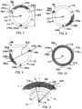
- FIG. 11is an enlarged sectional view of a flexure defining a circular segment in an embodiment of the invention.
- FIGS. 12 A and 12 Bdepict the deflection of the fiber optic force sensing assembly of FIG. 5 under an axial load and a lateral load, respectively;
- FIG. 13is an enlarged perspective view of a fiber optic force sensing assembly in a embodiment of the invention.
- FIGS. 13 A and 13 Bare sectional views of the force sensing assembly of FIG. 13 ;
- FIG. 14is an enlarged perspective view of a fiber optic force sensing assembly in a third embodiment of the invention.
- FIGS. 14 A and 14 Bare sectional views of the force sensing assembly of FIG. 14 ;
- FIG. 15is a sectional view of a fiber optic force sensing assembly in an embodiment of the invention.
- the displacement sensing system 40can comprise an electromagnetic source 42 , a coupler 44 , a receiver 46 , an operator console 47 operatively coupled with a microprocessor 48 and a computer-readable storage device 49 .
- the electromagnetic source 42outputs a transmitted radiation 50 of electromagnetic radiation that is substantially steady state in nature, such as a laser or a broadband light source.
- a transmission line 52such as a fiber optic cable carries the transmitted radiation 50 to the coupler 44 , which directs the transmitted radiation 50 through a transmitting/receiving line 54 and through a fiber optic element 53 ( FIG.
- the fiber optic element 53 of the catheter assembly 57 and transmitting/receiving line 54can be coupled through a connector 56 as depicted in FIG. 1 .
- the catheter assembly 57can have a width and a length suitable for insertion into a bodily vessel or organ.
- the catheter assembly 57comprises a proximal portion 57 a , a middle portion 57 b and a distal portion 57 c .
- the distal portion 57 ccan include an end effector 58 that houses the fiber optic sensing element 60 .
- the catheter assembly 57can be of a hollow construction (i.e., having a lumen) or of a non-hollow construction (i.e., no lumen), depending on the application.
- the catheter assembly 57includes a gap 55 that is responsive to a contact force exerted on the end effector 58 .
- a temperature sensor 62( FIG. 2 A ) is routed through the catheter assembly 57 , with a lead line 64 that exits the connector 56 .
- the lead line 64can be routed to a temperature sensing module 66 that conditions the signal received from the temperature sensor 62 and converts it to a digital signal 68 .
- the digital signal 68can then be routed to the microprocessor 48 for processing.
- an interferometric fiber optic sensing element 60 ais depicted as the fiber optic sensing element 60 in an embodiment of the invention.
- the transmitted radiation 50enters an interferometric gap 55 a , which is defined by a structural member 72 .
- the temperature sensor 62is arranged to sense the temperature of the structural member 72 A portion of the radiation that enters the interferometric gap 55 a is returned to the fiber optic element 53 of the catheter assembly 57 as reflected radiation 74 that defines a modulated waveform 74 a created, for example, by the multiple interreflection principle of a Fabry-Perot resonator. More discussion of the interferometric principle is found attendant to the discussion of FIG. 6 A below.
- an intensity-varying fiber optic sensing arrangement 60 bis depicted as the fiber optic sensing element 60 in an embodiment of the invention.
- the transmitted radiation 50enters an intensity-varying gap 55 b , a portion of which is reflected back to fiber optic element 53 .
- the intensity of the reflected radiation 74 b received by the fiber optic element 53varies inversely with the dimension of the intensity-varying gap 55 b.
- the reflected radiation 74can be transmitted back through the transmitting/receiving line 54 to the receiver 46 .
- the displacement sensing system 40can interrogate the displacement sensing element 60 at an exemplary and non-limiting rate of 10-Hz.
- the receiver 46is selected to detect a characteristic of the reflected radiation 74 corresponding to the dimension of the gap 55 (i.e., the frequency of the modulated waveform 74 a or the intensity of the reflected light 74 b ).
- the receiver 46manipulates and/or converts the incoming reflected radiation 74 into digital signals for processing by the microprocessor 48 .
- the fiber optic force sensing assembly 92can be configured as a multi-segmented structural member 96 that flexes in response to a contact force F imposed on a distal extremity 94 of the end effector 88 , e.g., when distal extremity 94 contacts the wall of a bodily vessel or organ.
- one or more end effectors 58 of different kindse.g., mapping electrodes or ablation electrodes, such as are known in the art for diagnosis or treatment of a vessel or organ can be utilized with the invention.
- the catheter assembly 57can be configured as an electrophysiology catheter for performing cardiac mapping and ablation.
- the catheter assembly 57can be configured to deliver drugs or bioactive agents to a vessel or organ wall or to perform minimally invasive procedures such as transmyocardial revascularization or cryo-ablation.
- a fiber optic force sensing assembly 98 aincluding a four-segment structural member 102 and a plurality of fiber optics 104 is depicted in an embodiment of the invention.
- the four-segment structural member 102defines a longitudinal axis 110 and includes an outer surface 112 .
- the four-segment structural member 102is divided into four segments 116 , identified as a proximal segment 118 , a first middle segment 120 , a second middle segment 122 and a distal segment 124 .
- the segments 116are sequentially adjacent each other in a serial arrangement along the longitudinal axis 110 .
- the segments 116are bridged by a plurality of flexures 128 , identified individually as flexures 128 a , 128 b and 128 c , thus defining a plurality of flexural axes 130 , identified individually as flexural axes 130 a , 130 b and 130 c (best depicted in FIGS. 7 , 8 and 9 ).
- adjacent members of the segments 116define a plurality of slots 136 , each having a separation dimension 138 and each defining a proximal plane 139 and a distal plane 140 ( FIG. 6 A ).
- each slot 136defines its own proximal plane 139 and distal plane 140 , depicted in FIG. 5 as 139 a through 139 c and 140 a through 140 c , respectively.
- the four-segment structural member 102can include a plurality of grooves 142 (identified as grooves 142 a , 142 b and 142 c ) formed on the outer surface 112 .
- the grooves 142can be spaced rotationally equidistant (e.g., spaced 120° apart for a 3-fiber system) about the longitudinal axis 110 and can be oriented in a substantially axial direction along the four-segment structural member 102 .
- the fiber optics 104(identified as fiber optics 104 a , 104 b and 104 c ) define a plurality of light propagation axes 148 and distal ends 150 (identified as 148 a through 148 c and 150 a through 150 c , respectively).
- the fiber optics 104are disposed in the grooves 142 and can be affixed thereto with a potting 144 such as epoxy such that the distal ends 150 terminate proximate the proximal planes 139 of the slots 136 ( FIG. 6 A ).
- the fiber optics 104can be press fit or otherwise fastened to the four-segment structural member 102 .
- the fiber optic 104can be bonded to the segment 116 adjacent the respective slot 136 to be interrogated.
- fiber optic 104 bcan be mounted within the portion of groove 142 b that is formed on the middle segment 122 .
- the remainder of the fiber optic 104 bcan be left to slide freely within the remainder of the groove 142 b , such that the fiber optic 104 b will not form a structural bridge between adjacent segments, which would inhibit the flexibility of the fiber optic force sensing assembly 98 a.
- the fiber optic 104 acan extend along the groove 142 a , terminating proximate the proximal plane 139 of the slot 136 a .
- fiber optics 104 a and 104 bcan extend along the grooves 142 b and 142 c , respectively, terminating proximate the slots 136 b and 136 c , respectively.
- reflecting members 151(identified as reflecting members 151 a , 151 b and 151 c ) each having a proximal end 152 (identified as proximal ends 152 a , 152 b and 152 c ) are arranged so that the proximal ends 152 are proximate the distal plane 140 of a given slot 136 .
- Each of the reflecting members 151is paired and substantially aligned with the distal end 150 of a corresponding one of the plurality of fiber optics 104 .
- a plurality of gaps 153(identified as gaps 153 a , 153 b and 153 c ) are defined, one between each distal end 150 of the respective fiber optic 104 and the proximal end 152 of the reflecting member 151 .
- proximate a given plane 139 or 140is defined for purposes of the claimed inventions as being closer to one of those planes than to the other, but not necessarily flush with the plane.
- the distal end 150 ais said to be “proximate” the proximal plane 139 a if it is flush with, slightly recessed from or extends slightly beyond the proximal plane 139 a (the latter being depicted in FIG. 6 A ) and closer to proximal plane 139 a than to distal plane 140 a .
- proximal end 152 a of the reflecting member 151 ais “proximate” the distal plane 140 a if it is flush with, slightly distal to or extending slightly proximal to the distal plane 140 a (again, the latter being depicted in FIG. 6 A ), and closer to distal plane 140 a than to proximal plane 139 a.
- the gaps 153can be, for example, interferometric or intensity-varying.
- An “interferometric gap” as used hereinis a gap having the attributes an interferometric resonator, such as found in a Michelson interferometer or a Fabry-Perot resonator.
- a “gap interferometer” as used hereinis an interferometer that utilizes an interferometric gap to produce an interference pattern.
- An “intensity-varying gap”is one configured to capture a reflected intensity that varies inversely with the dimension of the gap.
- the gaps 153may be characterized as having a dimension or operative length ⁇ ( ⁇ a being depicted for gap 153 a in FIG. 6 A ) defined as the distance between the distal end 150 of the fiber optic 104 and the respective proximal end 152 of the reflecting member 151 .
- the operative length ⁇can differ from the dimension of the respective slot 136 and can be different for each slot 136 .
- the operative length ⁇establishes the characteristics of the reflected radiation (i.e., the frequency of the interference pattern or the intensity of the reflected radiation) returned back through the fiber optic 104 .
- the distal ends 150can be faced with a semi-reflecting surface or coating 155 that re-reflects a portion of the light reflected from a highly reflective surface or coating 154 while substantially transmitting the remaining portion of the reflected light therethrough for detection by the displacement sensing system 40 .
- the highly reflective surface 154does not require a coating, but can be provided by the material of the reflecting member 151 .
- the fiber optic 104 a of FIG. 6 Ais depicted as having a free length L FO , defined as the distance between the distal end 150 a and the potting 144 that affixes the fiber optic 104 to the groove 142 a .
- the reflecting member 151 ais depicted as having a free length L RM , defined as the distance between the proximal end 152 a and the potting 144 that affixes the reflecting member 151 a to the groove 142 a .
- the distance between the pottings 144is referred to as the total distance L TOT .
- the total distance L TOT between the pottings 144will be substantially equal to the dimension of the slot 136 .
- the dimensions L TOT , L RM and L FOcan vary for each fiber optic/reflecting member pairing 104 a / 151 a , 104 b / 151 b and 104 c / 151 c.
- each of the light propagation axes 148 of the fiber optics 104is coincident with the proximal end 152 of the paired reflecting member 151 .
- the light propagation axis 148 ais subtended by the proximal end 152 a of the reflecting member 151 a .
- the proximal ends 152 of the reflecting members 151can be made highly reflective.
- the distal ends 150 of the fiber optics 104can be made only partially reflective to establish the Fabry-Perot effect.
- the interaction between the highly reflective proximal ends 152 of the reflecting members 151 and the partially reflective distal ends of the fiber optics 104creates interreflections therebetween, thus establishing an interference pattern having a frequency which depends on the dimension of the gap 153 .
- the resulting modulated waveform 74 ais transmitted back through the fiber optics 104 as explained in the discussions attendant FIGS. 1 and 2 .
- the distal ends 150 of the fiber optics 104are not treated with the semi-reflective coating, and in fact can be treated with an anti-reflective coating (not depicted).
- Such an arrangementcan enhance or optimize the intensity of reflected radiation that is returned to the receiver 46 via the fiber optic 53 ( FIG. 1 ).
- the size of the gap 153can be inferred from intensity of the reflected light returned as detected by the receiver 46 .
- the intensity of the reflected light collected by a given fiber optic 104can vary with the distance between the distal end 150 and the reflective surface 154 proximal end 152 of the reflecting member 151 .
- a fiber optic force sensing assembly 98 cis portrayed as having a spliced fiber optic 157 with an intrinsic interferometric cavity 158 in an embodiment of the invention.
- the fiber optic force sensing assembly 98 cincludes many of the same aspects as the force sensing assembly 98 a , which are identified by like-numbered numerical references.
- the depiction of FIG. 6 Blimns both the core 104 x and the cladding 104 y of the fiber optic 104 .
- the spliced fiber optic 157includes the fiber optic 104 and the reflecting member 151 , but instead of a gap being defined between non-touching ends, the intrinsic interferometric cavity 158 is captured between the distal end 150 of the fiber optic 104 and the proximal end 152 of the reflecting member 151 by splicing the ends 150 and 152 together.
- the gap 153is thus defined between the axial ends of the cavity 158 .
- the cavity 158is formed on at least one of the ends 150 and/or 152 .
- the depiction of FIG. 6 Bis a non-limiting portrayal of the cavity formed on the distal end 150 of the fiber optic 104 .
- the cavity 158can be formed, for example, by a chemical erosion or a laser ablation process that removes material from the core 104 x and leaves effectively only the cladding 104 y remaining.
- the highly reflective and partially reflective coatings 154 and 155can be applied to the ends of the reflecting member 151 and the fiber optic 104 , respectively, and the fiber optics 104 and the reflecting member 151 are spiced together.
- the spliced fiber optic 157 or any other version of an intrinsic interferometric devicewill mechanically bridge the slots 136 at the location of the deflection beam length 163 of the respective slot.
- the mechanical bridgingeffectively increases the rigidity of the force sensing assembly 98 c .
- the bending resistance or “stiffness” of the opposing flexure 128can be reduced in proportion to the increased rigidity caused by the presence of the bridging fiber optic. (See FIG. 11 and attendant discussion of area moments of inertia.)
- the elasticity of the assemblycan be delegated to the bridging fiber optics by elimination of the flexures 128 (not depicted).
- the structural memberis made of a metallic material, such as titanium, whereas the fiber optics are made of a material that is highly transparent at select wavelengths, such as silica or sapphire.
- the coefficient of thermal expansion (CTE) of these materialsis substantially different, with silica being in the range of 1 to 2 ⁇ 10 ⁇ 6 m/m-K (1 to 2 ⁇ /K), and titanium being more on the order of 8 ⁇ /K.
- the difference in the respective CTEcan cause substantial thermally-induce changes in the operative lengths ⁇ of the gaps 153 that, if uncorrected or uncompensated, can lead to large errors in the indications of contact force.
- the segments 116 and flexures 128 of the metallic materialwill change in proportion to the CTE of the metallic material. Accordingly, the total distance between the pottings 144 of a given fiber optic 104 and its paired reflecting member 151 will change in proportion to the CTE of the metallic material and for a given temperature change. Meanwhile, the free lengths L FO and L RM will change in proportion to the CTEs of the reflecting member 151 and the fiber optic 104 , respectively.
- ⁇is the CTE
- ⁇ Tis the local change in temperature
- ⁇is the operative length of the gap 153 /cavity 158
- subscripts M, FO and RMdesignate the metal, fiber optic and reflecting member, respectively.
- the quantity ⁇ M ⁇ T M ⁇ L TOTis the change in length between the pottings 144 that is attributed to temperature change of the metallic structural member
- the quantities ⁇ FO ⁇ T FO ⁇ L FO and ⁇ T RM ⁇ T RM ⁇ L RMare the changes in length of the extended portions of the fiber optic 104 and the reflecting member 151 due to their respective temperature changes.
- the quantity ( ⁇ M ⁇ L TOT ⁇ FO ⁇ L FO ⁇ RM ⁇ L RM )can be reasonably approximated as a constant value across the temperature range of interest (e.g., from 0 to 40° C.).
- the value of ⁇can be calibrated by measuring ⁇ at different ⁇ T.
- the value of ⁇can be approximated as a constant, or taken as a temperature-dependent parameter by performing a curvefit to the calibration data.
- Eqn. (1)can also be utilized for establishing relationships for the passive correction of thermally-induced dimensional changes.
- Physical realization of Eqn. (6)is achieved by proper selection of the various parameters, thus holding the operative length ⁇ constant across a range of temperature changes ⁇ T. By assigning values to all but one of the parameters in Eqn. (6), the value of the remaining parameter can be established.
- Equation (3)can be used generally for parametric studies for selecting proper free lengths for given combinations of CTEs available.
- the presence of the reflecting members 151 of the FIG. 6 A and FIG. 6 B configurationsoffers a way to passively compensate for thermally induced changes in the dimensions of the structural member 102 and the attendant changes in the operative length ⁇ .
- a fiber optic force sensing assembly 98 bis depicted in an embodiment of the invention.
- the fiber optic 104is mounted substantially flush with the proximal plane 139 of the slot 136
- the reflecting member 151is arranged to extend substantially the length L TOT except for the allowance for the operative length ⁇ .
- the reflecting member 151is made of the same material as the structural member 102 , or at least of a material that has the same CTE as the reflecting member 151 .
- the structural member 102is fabricated from titanium, and the reflecting members 151 comprise titanium rods or wires that are affixed to the structural member 102 with the potting 144 (as depicted) or by a welding process. In another embodiment (not depicted), the reflecting members 151 are integrally formed with the structural member 102 .
- matching the CTE of the structural member 102 and the reflecting member 105substantially compensates for temperature changes of these components.
- the length L RMis only slightly less than the separation dimension 138 , the change in the length L RM of the reflecting member 151 is close to the change in the separation dimension 138 . In this way, the change in the separation dimension 138 is largely offset by the change in the reflecting member 151 .
- a simplificationresults when the fiber optic 104 does not extend beyond the potting 144 , such as the presented in the configuration of FIG. 6 C .
- the sensing assembly 98 bundergoes an increase in temperature. This will cause the separation dimensions 138 of the slots 136 to increase, thereby causing the distance L TOT to increase also.
- the reflecting member 151being of the same CTE and almost of the same length, will increase in length by almost the same length, causing the reflecting member 151 to grow towards the distal end 150 of the fiber optic 104 at the same time that the increase in the separation dimension brings the distal end 150 of the fiber optic towards the proximal end 152 of the reflecting member 151 .
- the same mechanism of compensationoccurs when the sensing assembly 98 b decreases in temperature.
- the separation dimensions 138decrease, and so does the length L RM of the reflecting member 151 , causing the reflecting member to shrink away from the distal end 150 of the fiber optic 104 just as the decrease in the separation dimension brings the distal end 150 of the fiber optic towards the proximal end 152 of the reflecting member 151 .
- the simplificationis rooted in the reduction of the free length L FO of the fiber optic 104 to zero.
- L FO0
- the change in the length between the pottings 144 due to thermal effectsis proportional to the dimension L TOT between pottings 144 . That is, the greater the value of L TOT , the greater the potential error due to thermal changes. Therefore, the value of L TOT can be substantially greater for the fiber optic force sensing assembly 192 a than for the assembly 180 .
- the operative length ⁇is approximately 15 ⁇ m, with force sensitivity in the range of 0.1 to 0.25 grams of force (gmf) per nanometer (nm) of axial displacement (i.e., a displacement sensitivity ranging from 4 to 10 nm/gmf), where a “gram of force” is equivalent to the weight of 1 gram of mass at standard gravity.
- the CTE of titaniumis approximately 8 ⁇ /K.
- Representative (i.e., non-limiting) values for L TOTrange from approximately 0.2 mm to 1 mm.
- the sensitivity to temperature changeranges from 0.4 to 1 gmf/K. In many applications, it is desirable to resolve the force to within ⁇ 1 gmf.
- desired resolution of the force sensing systemcan become dwarfed by the thermally-induced error in uncompensated systems where temperature changes several Kelvins during ablation operations.
- the reflecting members 151having highly reflective proximal ends 152 , are not relied upon to transmit light.
- the CTE of the reflecting members 151can be tailored for a desired CTE without consideration of the light transmittance properties. Therefore, in one embodiment, the reflecting members 151 can be replaced with fibers having a high CTE, provided, for example, by aluminum doped fibers having a CTE of around 4 ⁇ /K. In another embodiment fibers of sapphire with CTE of 12 ⁇ /K can be employed. Fine tuning of the passive compensation can be obtained by changing the relative length of the sapphire normal fiber in accordance with Eqn. (6).
- the material of the reflecting member 105can have sufficient reflectance to negate the need for a coating.
- Proximal ends 152can be polished to provide the totally reflective surface, and/or can still be coated with a coating.
- each of the flexure portions 128can be instrumented with temperature sensors for active compensation of temperature change.
- the depiction of FIG. 4presents a thermocouple 149 that is routed along the exterior of the structural member 102 and arranged so that the temperature sensing junction of the thermocouple 149 is in contact with the outside surface of flexure portion 128 b .
- the temperature sensorcan be routed along the interior of the structural member 102 and placed in sensing contact with the interior surfaces of the flexure portions.
- each of the flexure portions 128 a , 128 b and 128 care instrumented with a respective temperature sensor (not depicted). By sensing the temperature change of each flexure 128 , the thermally-induced changes to the dimensions 138 can be inferred.
- the temperature sensorscan be taken as the ⁇ T to solve for the change in the gap dimension ⁇ (e.g., used to solve Eqns. (3), (4) or (12)) for active compensation.
- the values provided by the temperature sensorscan be utilized in a calibration arrangement such as described in Leo '092, where the change in temperature of the local flexure ⁇ T M is taken as the change in temperature of the displacement sensor. It is noted that, unlike the teachings of Leo '092, the temperature sensors 149 are not necessarily proximate the fiber optics 104 or reflecting members 151 , but instead can actually be diametrically opposed to the fiber optic/reflecting member pairing that is being corrected by the temperature sensor 149 .
- a method for actively compensating for thermally induced errorscan be programmed into the computer-readable storage device 49 ( FIG. 1 ).
- the computer-readable storage device 49can be programmed to receive information from the temperature sensing module 66 based on signals received from the temperature sensor 62 .
- a reference measurementcan be made, for example, at room temperature with the force sensing assembly in a no-load condition.
- a temperature change of the force sensing assembly relative to the reference temperaturecan be measured, for example, at a flexure 128 of structural member 102 .
- the computer-readable storage device 49can be programmed to compute the change in the gap dimension due to the temperature change using, for example, the relationship expressed in Eqns. (3), (4) or (12).
- the slots 136can be formed so that they extend laterally through a major portion of the four-segment structural member 102 . Also, the slots 136 can be oriented to extend substantially normal to the longitudinal axis 110 (as depicted) or at an acute angle with respect to the longitudinal axis (not depicted).
- the structural membercomprises a hollow cylindrical tube 156 with the slots 136 being formed from one side of the hollow cylindrical tube 156 , extending therethrough and across the inner diameter 160 of the hollow cylindrical tube 156 to a depth 162 ( FIG. 7 ).
- the flexure portions 128 remaining after the slots 136 are formedsubstantially define, for example, a major circular segment with a minor circular segment cut out (e.g., FIGS. 7 - 9 and 11 ). Alternatively, a circular segment with no cut out can also be defined (e.g., FIG. 14 B ).
- the depth 162 of the slots 136 traverse the inner diameter 160 of the hollow cylindrical tube 156can be varied to establish a desired flexibility of the flexure 128 . That is, the greater the depth 162 of the slot 136 , the more flexible the flexure portion 128 .
- the slots 136can be formed by the various techniques and methods available to the artisan, such as but not limited to sawing, laser cutting or electro-discharge machining (EDM).
- the slots 136can be formed so that the flexure portions 128 define non-concentric flexural axes 130 .
- non-concentric flexural axesit is meant that the respective flexural axes are not in axial alignment. That is, flexural axis 130 a defines an axis in space that is non-coincident with either flexural axes 130 b and 130 c , and flexural axis 130 b defines and axis in space that is non-coincident with flexural axis 130 c .
- the flexural axes 130are diametrically opposed to the location of the distal end 150 of the fiber optic 104 that terminates in the same slot 136 as is bridged by the flexural axis.
- flexure portion 128 acan be diametrically opposed to distal end 150 a , and so on.
- a cross-section 164 of the flexure portion 128is depicted in FIG. 11 .
- the cross-sectionis characterized by an area centroid C through which the neutral or flexural axis 130 passes, and as having inertial axes x-x and y-y that are orthogonal, where the inertial axis x-x identifies the axis about which the area moment of inertia is minimum.
- the y-y axispasses substantially through the longitudinal axis 110 .
- the circular segment geometryprovides substantially greater stiffness about inertial axis y-y than about inertial axis x-x. Consider a circular segment having an angle of ⁇ /2 radians (90°).
- the area moment of inertia about the inertial axis y-yis about twenty times greater than the area moment of inertia about the inertial axis x-x. Accordingly, forces that cause a moment about inertial axis y-y will typically cause substantially less bending relative to the same moment being applied about inertial axis x-x. Therefore, moments about inertial axis y-y tend to be transferred as a torsional force between adjacent sections, whereas moments about inertial axis x-x will tend to cause a deformation of the flexure portion 128 and a subsequent deflection between the adjacent segments 116 .
- a deflection beam length 163is defined as the distance between the flexural axis 130 and the propagation axis 148 at the distal end 150 of the corresponding fiber optic 104 , the distance being normal to the inertial axis x-x.
- the deflection beam length 163is maximized, and so is the attendant change in the operative length ⁇ of the gap 153 between the distal end 150 of the fiber optic 104 and the proximal end 152 of the reflecting member 151 .
- FIGS. 12 A and 12 Boperation of the fiber optic force sensing assembly 98 a in response to an axial force FA and a lateral force FL, respectively, is depicted in an embodiment of the invention.
- the axial force FAcauses the segments 116 to bend about the inertial axes x-x of the various flexure portions 128 in substantially a pure bending action, thus causing the dimension of the slots 136 proximate the distal ends 150 of the fiber optics 104 to decrease ( FIG. 12 A ).
- the lateral force FLwill generally cause a more complex deformation of the four-segment structural member 102 .
- the lateral force FLis applied substantially parallel to the inertial axis y-y of flexure portion 128 a . This causes flexure portion 128 a to translate a moment between the distal segment 124 and the second middle segment 122 while causing a negligible change in the dimension ⁇ a of gap 153 a .
- the translated momentcauses flexure portions 128 b and 128 c to bend about their respective inertial axes x-x, which in turn causes the slot 136 b to close proximate distal end 150 b of fiber optic 104 b and the slot 136 c to open proximate the distal end 150 c of fiber optic 104 c .
- neither flexure portion 128 b or 128 care in pure bending because lateral force FL does not act normal to the respective inertial axes x-x.
- the degree of bending about the inertial axes x-xwill generally be proportional to the component of the lateral force FL that acts normal thereto.
- FIGS. 12 A and 12 Bshow a purely axial and a purely lateral force, respectively, but that a combined force vector in three-dimensional space having an axial and a lateral component will combine the general effects depicted by superposition. Accordingly, a force vector in three-dimensional space can be resolved by calibrating the response of the fiber optic force sensing assembly under these pure loads and superimposing the various responses to infer the axial and lateral components.
- the preceding embodimentscan provide a mechanical amplification of the change in the operative length ⁇ relative to the strain experienced by the flexure portions 128 .
- the deflection of the segments 116 at a position normal to the inertial axis x-x of a respective one of the flexure portions 128is proportional to the deflection beam length 163 between the inertial axis x-x and the respective location of the distal end 150 of the respective fiber optic 104 . Accordingly, change in the dimension 138 of the slot 136 will be greatest at a location that is diametrically opposed to the flexural axis 130 . Thus, for embodiments where the distal ends 150 of the fiber optics 104 in diametric opposition to the flexural axes 130 (as depicted in FIG. 9 ), the fiber optics 104 are in a position of greatest sensitivity.
- the structural member 102can be fabricated from other forms besides a hollow cylindrical tube, including but not limited to tubes or rods that define a square, rectangular or cross-shaped cross-section.
- the structural member 102can comprise a metallic material, such as titanium or platinum/iridium, or a non-metallic material such as a polymer or ceramic.
- the potting 144can comprise a glue or epoxy and can be selected to closely match the coefficient of thermal expansion (CTE) of the structural member 102 and/or fiber optics 104 , or to provide a CTE that is between the CTEs of the structural member 102 and fiber optics 104 to provide a transition therebetween.
- the potting 144can also be chosen for flexibility so that the thermal growth of the adhesive film does not impose a substantial strain on the fiber optics 104 . Use of a very thin film of potting 144 can, in some instances, mitigate the strain-inducing effects of differential thermal expansion between the fiber optic 104 and the structural member 102 .
- a fiber optic force sensing assembly 180 having a three-segment structural member 182is depicted in an embodiment of the invention.
- the fiber optic force sensing assembly 180includes many of the same aspects as the assembly 98 a , which are identified by like-numbered numerical references.
- a distinction between the three-segment structural member 182 and the four-segment structural member 102is that the three-segment structural member 182 includes only a single middle segment 184 between the proximal and distal segments 118 and 124 .
- the three-segment structural memberis characterized by two flexures 186 a and 186 b that separate the middle segment 184 from the proximal and distal segments 118 and 124 , respectively, thereby defining a distal or “distal-most” slot 188 a and a proximal slot 188 b , respectively.
- the arrangement between the fiber optics 104 and reflecting members 151can be the same as the various configurations described and discussed in relation to FIG. 6 .
- the reflecting memberscan be configured for passive compensation of thermal expansion/contraction, or instrumented with temperature sensors for active compensation. Both passive and active compensation are described above.
- the flexures 186 a and 186 bdefine respective flexural axes 190 a and 190 b that are rotationally spaced 180° apart (i.e., are diametrically opposed) so that the flexural axes 190 a and 190 b and the longitudinal axis 110 are substantially co-planar. Also by this arrangement, the inertial axes y-y of the flexures 186 a and 186 b are substantially coplanar.
- the fiber optics 104 a and 104 c and the corresponding reflecting members 151 a and 151 c of the fiber optic force sensing assembly 180extend into the same distal slot 188 a , and are spaced at an angle ⁇ rotationally equidistant from the inertial axes y-y but respectively in opposite directions + ⁇ and ⁇ .
- the three-segment structural member 182will respond to axial and lateral force components FA and FL in generally the same manner similar as that depicted in FIGS. 12 A and 12 B .
- the specific response to lateral force components FLx and FLy, depicted in FIG. 13 Bwhere FLx is a lateral force component acting normal to inertial axis x-x and FLy is a lateral force component acting normal to inertial axis y-y.
- the lateral force component FLxwill cause pure bending about the inertial axes x-x, causing dimensional changes in the distal and proximal slots 188 a and 188 b akin to the changes in dimensions 138 c and 138 b in slots 136 c and 136 b , respectively, that is depicted in FIG. 12 B .
- the operative lengths ⁇ of the various gaps 153change in congruence with the dimensional changes of the distal and proximal slots 188 a and 188 b.
- Detection of the lateral force component FLyrelies on deflection about the inertial axis y-y of the flexure 186 a , which is sensed by changes in the operative lengths ⁇ of the gap 153 a and 153 c . Because the stiffness of the flexures 186 about the y-y inertial axes is substantially greater than the stiffness about the x-x inertial axes, the sensitivity (measured displacement per unit force) to FLy force components is not as high as for FLx force components.
- a fiber optic force sensing assembly 192 autilizing the three-segment structural member 182 is depicted in an embodiment of the invention.
- the fiber optic force sensing assembly 192 aincludes many of the same aspects as the assembly 180 , which are identified by like-numbered numerical references.
- a distinction between the assemblies 180 and 192 ais that, for the fiber optic force sensing assembly 192 a , all of the fiber optics 104 are anchored to the proximal segment 118 , pass through the proximal slot 188 b and the single middle segment 184 , and terminate proximate the distal slot 188 a .
- the fiber optic force sensing assembly 192 ais that the angular distribution of the optical fibers 104 and paired reflecting members 151 is not uniform, and that the fiber optics 104 /reflecting members 151 are positioned for greater distances from the y-y inertial axes than with the fiber optic force sensing assembly 180 of FIG. 13 . Accordingly, the rotational displacements ⁇ relative to the y-y inertial axis are not all equal, but rather can be characterized by unique values ⁇ A, ⁇ B and ⁇ C. In the depicted embodiment, ⁇ A and ⁇ B are substantially equal.
- the arrangement of the fiber optic force sensing assembly 192 a depicted in FIG. 14is more sensitive to lateral force components FLy than is the assembly 180 for several reasons.
- the displacement sensedis the accumulation of the displacements about both the flexures 186 a and 186 b .
- the distance between the slots 188 a and 188 b afforded by the middle segment 184provides a mechanical amplification of the flexural displacement about inertial axis y-y of the flexure 186 b .
- the rotational displacements ⁇ of the fiber optic 104 and reflecting member 151 pairings relative to the plane of the y-y inertial axesare either at 90° ( ⁇ C) or closer to 90° ( ⁇ A, ⁇ B) than would be in a uniform angular distribution where the three fiber optics 104 are spaced 120° apart.
- the enhancements to the sensitivity of the FLy componentare accomplished in part by a beneficial tradeoff with the sensitivity to the FLx components.
- the sensitivity to lateral forces of the fiber optic force sensing assembly 192 a depicted in FIG. 14is more uniform (less directionally dependent) than is the fiber optic force sensing assembly 180 of FIG. 13 .
- the same passive compensation of changes due to temperature changecan be implemented in both the FIG. 13 and the FIG. 14 configurations as discussed attendant to FIGS. 6 A and 6 B above.
- Active compensation for the fiber optic force sensing assemblies 180 or 192 a of FIGS. 13 and 14can also be enabled by instrumenting flexures 186 a and 186 b with temperature sensors.
- a fiber optic force sensing assembly 192 bis depicted in an embodiment of the invention.
- the fiber optic force sensing assembly 192 bhas many of the same aspects as the fiber optic force sensing assembly 192 a .
- a primary difference between assemblies 192 a and 192 bare that the reflecting members 151 extend through the distal slot 188 a and are optically coupled with the fiber optics 104 near the proximal slot 188 b .
- the reflecting members 151are also made of the same material as the three-segment structural member 182 .
- the reflecting members 151are of a different material, but have the same CTE as the three-segment structural member 182 .
- the fiber optic force sensing assembly 192 boffers the same force sensitivity advantages as fiber optic force sensing assembly 192 a .
- the fiber optics 104do not extend substantially beyond the potting 144 , the same benefits explained above in relation to FIG. 6 C are realized. See Eqns. (9)-(12) and attendant discussion.
Landscapes
- Health & Medical Sciences (AREA)
- Life Sciences & Earth Sciences (AREA)
- Surgery (AREA)
- Physics & Mathematics (AREA)
- General Health & Medical Sciences (AREA)
- Public Health (AREA)
- Engineering & Computer Science (AREA)
- Biomedical Technology (AREA)
- Heart & Thoracic Surgery (AREA)
- Medical Informatics (AREA)
- Veterinary Medicine (AREA)
- Molecular Biology (AREA)
- Pathology (AREA)
- Animal Behavior & Ethology (AREA)
- Biophysics (AREA)
- General Physics & Mathematics (AREA)
- Oral & Maxillofacial Surgery (AREA)
- Nuclear Medicine, Radiotherapy & Molecular Imaging (AREA)
- Media Introduction/Drainage Providing Device (AREA)
- Length Measuring Devices By Optical Means (AREA)
Abstract
Description
- receiving information from the temperature sensing module based on signals received from the temperature sensor;
- determining a temperature change of the flexure based on the information, the temperature change being relative to a reference temperature; and
- inferring a change in the gap based on the temperature change of the flexure.
(1+αM·ΔTM)·LTOT−(1+αFO·ΔTFO)·LFO−(1+αRM·ΔTRM)·LRM)·LRM=δ Eqn. (1)
where α is the CTE, ΔT is the local change in temperature, δ is the operative length of the
∂δ/∂T=αM·LTOT−αFO·LFO−αRM·LRM Eqn. (2)
Thus, for a given total temperature change ΔT, a thermally-induced change in the gap dimension Δδ is approximated by
Δδ=(αM·LTOT−αFO·LFO−αRM·LRM)·ΔT Eqn. (3)
where ΔT is the change in temperature relative to a reference temperature. Knowing the various α and L values of Eqn. 3, one can actively compensate for the thermally-induced change in gap dimension Δδ by measuring the ΔT.
Δδ=Ψ·ΔT Eqn. (4)
where Ψ=(αM·LTOT−αFO·LFO−αRM·LRM). In one embodiment, the value of Ψ can be calibrated by measuring Δδ at different ΔT. The value of Ψ can be approximated as a constant, or taken as a temperature-dependent parameter by performing a curvefit to the calibration data.
LTOT−LFO−LRM=δ Eqn. (5)
A simplifying assumption is to assume ΔTFOand ΔTRMare dominated by and equal to ΔTM. That is, ΔTM=ΔTFO=ΔTRM=ΔT.
αM·LTOT−αFO·LFO−αRM·LRM=0 Eqn. (6)
Physical realization of Eqn. (6) is achieved by proper selection of the various parameters, thus holding the operative length δ constant across a range of temperature changes ΔT. By assigning values to all but one of the parameters in Eqn. (6), the value of the remaining parameter can be established.
LRM=(αM·LTOT−αFO·LFO)/αRM Eqn. (7)
Alternatively, for example, if the CTEs αMand αFOare known, and the lengths LTOT, LFOand LRMare assigned values, the required CTE of the reflecting member αRMcan be solved:
αRM=(αM·LTOT−αFO·LFO)/LRM Eqn. (8)
(1+αM·ΔTM)·LTOT−(1+αRM·ΔTRM)·LRM=δ Eqn. (9)
Assuming ΔTM=ΔTRM=ΔT, and noting that a change in the temperature ∂T is the same as a change in the ∂ΔT, a change in the gap dimension ∂δ due to the change in temperature ∂T is expressed as
∂δ/∂T=αM·LTOT−αRM·LRM Eqn. (10)
For systems where the
∂δ/∂T=αM·(LTOT·LRM)=αM·δ Eqn. (11)
For a given total temperature change ΔT, a change in the gap dimension Δδ is approximated by
Δδ=αM·δ·ΔT Eqn. (12)
It is noted that Eqn. (12) applies regardless of the lengths LTOTor LRM.
Claims (18)
Priority Applications (2)
| Application Number | Priority Date | Filing Date | Title |
|---|---|---|---|
| US16/736,570US11564628B2 (en) | 2011-04-14 | 2020-01-07 | Compact force sensor for catheters |
| US18/145,737US20230200736A1 (en) | 2011-04-14 | 2022-12-22 | Compact force sensor for catheters |
Applications Claiming Priority (3)
| Application Number | Priority Date | Filing Date | Title |
|---|---|---|---|
| US201161475384P | 2011-04-14 | 2011-04-14 | |
| US13/447,813US10561368B2 (en) | 2011-04-14 | 2012-04-16 | Compact force sensor for catheters |
| US16/736,570US11564628B2 (en) | 2011-04-14 | 2020-01-07 | Compact force sensor for catheters |
Related Parent Applications (1)
| Application Number | Title | Priority Date | Filing Date |
|---|---|---|---|
| US13/447,813DivisionUS10561368B2 (en) | 2011-04-14 | 2012-04-16 | Compact force sensor for catheters |
Related Child Applications (1)
| Application Number | Title | Priority Date | Filing Date |
|---|---|---|---|
| US18/145,737ContinuationUS20230200736A1 (en) | 2011-04-14 | 2022-12-22 | Compact force sensor for catheters |
Publications (2)
| Publication Number | Publication Date |
|---|---|
| US20200214634A1 US20200214634A1 (en) | 2020-07-09 |
| US11564628B2true US11564628B2 (en) | 2023-01-31 |
Family
ID=46001842
Family Applications (3)
| Application Number | Title | Priority Date | Filing Date |
|---|---|---|---|
| US13/447,813Active2035-12-06US10561368B2 (en) | 2011-04-14 | 2012-04-16 | Compact force sensor for catheters |
| US16/736,570Active2033-08-23US11564628B2 (en) | 2011-04-14 | 2020-01-07 | Compact force sensor for catheters |
| US18/145,737PendingUS20230200736A1 (en) | 2011-04-14 | 2022-12-22 | Compact force sensor for catheters |
Family Applications Before (1)
| Application Number | Title | Priority Date | Filing Date |
|---|---|---|---|
| US13/447,813Active2035-12-06US10561368B2 (en) | 2011-04-14 | 2012-04-16 | Compact force sensor for catheters |
Family Applications After (1)
| Application Number | Title | Priority Date | Filing Date |
|---|---|---|---|
| US18/145,737PendingUS20230200736A1 (en) | 2011-04-14 | 2022-12-22 | Compact force sensor for catheters |
Country Status (5)
| Country | Link |
|---|---|
| US (3) | US10561368B2 (en) |
| EP (1) | EP2696777B1 (en) |
| JP (2) | JP6177230B2 (en) |
| CN (1) | CN103607961B (en) |
| WO (1) | WO2012142588A1 (en) |
Families Citing this family (70)
| Publication number | Priority date | Publication date | Assignee | Title |
|---|---|---|---|---|
| US8075498B2 (en) | 2005-03-04 | 2011-12-13 | Endosense Sa | Medical apparatus system having optical fiber load sensing capability |
| EP2363073B1 (en)* | 2005-08-01 | 2015-10-07 | St. Jude Medical Luxembourg Holding S.à.r.l. | Medical apparatus system having optical fiber load sensing capability |
| US8567265B2 (en) | 2006-06-09 | 2013-10-29 | Endosense, SA | Triaxial fiber optic force sensing catheter |
| US8622935B1 (en) | 2007-05-25 | 2014-01-07 | Endosense Sa | Elongated surgical manipulator with body position and distal force sensing |
| CN103328033B (en) | 2010-11-09 | 2016-05-18 | 奥普森斯公司 | There is the seal wire of internal pressure sensor |
| CN103607961B (en) | 2011-04-14 | 2016-12-14 | 圣犹达医疗用品卢森堡控股有限公司 | Compact force sensor for conduit |
| EP2626680B1 (en)* | 2012-02-07 | 2015-10-07 | Sensoptic SA | Optical force sensing element and microsurgical instrument |
| EP2887863B1 (en) | 2012-08-27 | 2019-11-27 | Boston Scientific Scimed, Inc. | Pressure-sensing medical device system |
| CN105209102B (en) | 2013-03-15 | 2018-10-02 | 波士顿科学国际有限公司 | Pressure-sensing seal wire |
| CN105682544B (en) | 2013-05-22 | 2019-09-24 | 波士顿科学国际有限公司 | Pressure detecting godet system including optical connector optical cable |
| WO2015013646A1 (en) | 2013-07-26 | 2015-01-29 | Boston Scientific Scimed, Inc. | Ffr sensor head design that minimizes stress induced pressure offsets |
| US10835182B2 (en) | 2013-08-14 | 2020-11-17 | Boston Scientific Scimed, Inc. | Medical device systems including an optical fiber with a tapered core |
| WO2015057518A1 (en) | 2013-10-14 | 2015-04-23 | Boston Scientific Scimed, Inc. | Pressure sensing guidewire and methods for calculating fractional flow reserve |
| US9743991B2 (en) | 2013-10-21 | 2017-08-29 | Biosense Webster (Israel) Ltd. | Real-time estimation of tissue perforation risk during minimally invasive medical procedure |
| US10932679B2 (en) | 2014-03-18 | 2021-03-02 | Boston Scientific Scimed, Inc. | Pressure sensing guidewires and methods of use |
| US10219702B2 (en) | 2014-03-26 | 2019-03-05 | St. Jude Medical, Cardiology Division, Inc. | Single fiber force-sensing of both axial and bending catheter tip forces |
| EP3132296B1 (en) | 2014-04-17 | 2023-01-04 | Boston Scientific Scimed, Inc. | Self-cleaning optical connector |
| WO2015187385A1 (en) | 2014-06-04 | 2015-12-10 | Boston Scientific Scimed, Inc. | Pressure sensing guidewire systems with reduced pressure offsets |
| US9955917B2 (en)* | 2014-06-11 | 2018-05-01 | Vascomed Gmbh | Planar logic board for ablation catheter with force measurement functionality |
| WO2016019207A1 (en)* | 2014-08-01 | 2016-02-04 | Boston Scientific Scimed, Inc. | Pressure sensing guidewires |
| CN107405089B (en) | 2014-12-05 | 2020-09-04 | 波士顿科学国际有限公司 | Pressure sensing guide wire |
| JP6443803B2 (en)* | 2015-01-08 | 2018-12-26 | 住友電工スチールワイヤー株式会社 | Coated PC steel strand |
| US10564057B2 (en) | 2015-03-23 | 2020-02-18 | Farrokh Janabi-Sharifi | Temperature invariant force and torque sensor assemblies |
| US9498300B1 (en)* | 2015-07-30 | 2016-11-22 | Novartis Ag | Communication system for surgical devices |
| US10575754B2 (en) | 2015-09-23 | 2020-03-03 | Covidien Lp | Catheter having a sensor and an extended working channel |
| CN105343984A (en)* | 2015-10-14 | 2016-02-24 | 乐普(北京)医疗器械股份有限公司 | Guide wire |
| EP3376988B1 (en) | 2015-11-19 | 2023-08-23 | Covidien LP | Optical force sensor for robotic surgical system |
| US20170143416A1 (en)* | 2015-11-21 | 2017-05-25 | Boston Scientific Scimed Inc. | Force sensing catheter with a slotted tube element |
| WO2017112607A1 (en)* | 2015-12-20 | 2017-06-29 | Boston Scientific Scimed Inc. | Micro induction position sensor |
| US11445937B2 (en) | 2016-01-07 | 2022-09-20 | St. Jude Medical International Holding S.À R.L. | Medical device with multi-core fiber for optical sensing |
| CN108463265B (en)* | 2016-01-19 | 2021-06-01 | 圣犹达医疗用品心脏病学部门有限公司 | Nondestructive connector and catheter using the same |
| AU2017212715B2 (en) | 2016-01-29 | 2019-08-08 | Boston Scientific Scimed, Inc. | Force sensing catheter with impedance-guided orientation |
| CN109069840B (en) | 2016-02-04 | 2022-03-15 | 心脏起搏器股份公司 | Delivery system with force sensor for leadless cardiac devices |
| EP3419514B1 (en) | 2016-02-23 | 2023-08-23 | Boston Scientific Scimed, Inc. | Pressure sensing guidewire systems including an optical connector cable |
| CN108883256B (en)* | 2016-03-30 | 2022-07-19 | 皇家飞利浦有限公司 | Torque devices for use with intravascular devices and associated systems and methods |
| KR101797353B1 (en) | 2016-03-31 | 2017-11-14 | 성균관대학교산학협력단 | Force sensor using optical fibers in series, manufacture method of the same, medical device including the same |
| KR101797352B1 (en) | 2016-03-31 | 2017-11-14 | 성균관대학교산학협력단 | Force sensor using optical fiber and capillary, manufacture method of the same, medical device including the same |
| US11369431B2 (en) | 2016-06-11 | 2022-06-28 | Boston Scientific Scimed Inc. | Inductive double flat coil displacement sensor |
| CN110063788B (en)* | 2016-07-29 | 2021-04-30 | 上海微创电生理医疗科技股份有限公司 | Pressure sensor and electrophysiology catheter |
| US10595951B2 (en)* | 2016-08-15 | 2020-03-24 | Covidien Lp | Force sensor for surgical devices |
| US11559349B2 (en) | 2016-09-12 | 2023-01-24 | Biosense Webster (Israel) Ltd. | Ablation catheter with a flexible printed circuit board |
| US20180071009A1 (en)* | 2016-09-12 | 2018-03-15 | Biosense Webster (Israel) Ltd. | Ablation catheter with strain gauges |
| US11911093B2 (en) | 2016-09-12 | 2024-02-27 | Biosense Webster (Israel) Ltd. | Irrigation system for a catheter |
| CN106768500A (en)* | 2017-01-23 | 2017-05-31 | 湖南埃普特医疗器械有限公司 | A kind of medical catheter device for pressure measurement |
| JP6924287B2 (en)* | 2017-08-02 | 2021-08-25 | セント・ジュード・メディカル・インターナショナル・ホールディング・エスエーアールエルSt. Jude Medical International Holding S.a,r.l. | Optical force detection catheter system |
| CN116327157B (en) | 2017-08-03 | 2025-09-30 | 波士顿科学国际有限公司 | Methods for assessing fractional flow reserve |
| WO2019037071A1 (en)* | 2017-08-25 | 2019-02-28 | Cheng Weyland | Device and method for feedback and control using optical fibers in catheters |
| CN108042162B (en)* | 2017-12-21 | 2020-06-16 | 微创(上海)医疗机器人有限公司 | Surgical robot system and surgical instrument thereof |
| US10773051B2 (en) | 2018-01-24 | 2020-09-15 | Covidien Lp | Methods of manufacturing a catheter having a sensor |
| US10773053B2 (en) | 2018-01-24 | 2020-09-15 | Covidien Lp | Methods of manufacturing a catheter having a sensor |
| CN108066881B (en)* | 2018-01-29 | 2021-01-29 | 天津大学 | Vessel intervention catheter, device, contact force detection method and detection device |
| US11311196B2 (en) | 2018-02-23 | 2022-04-26 | Boston Scientific Scimed, Inc. | Methods for assessing a vessel with sequential physiological measurements |
| EP3768156B1 (en) | 2018-03-23 | 2023-09-20 | Boston Scientific Scimed, Inc. | Medical device with pressure sensor |
| WO2019193545A1 (en)* | 2018-04-05 | 2019-10-10 | St. Jude Medical International Holding S.À R.L | Force sensing catheter system |
| WO2019195721A1 (en) | 2018-04-06 | 2019-10-10 | Boston Scientific Scimed, Inc. | Medical device with pressure sensor |
| CN119564167A (en) | 2018-04-18 | 2025-03-07 | 波士顿科学国际有限公司 | System for vascular assessment using continuous physiological measurements |
| US20210228272A1 (en)* | 2018-08-07 | 2021-07-29 | St. Jude Medical International Holding S.À R.L. | Fluid gel for fiber optic gap |
| US11326970B2 (en)* | 2020-04-17 | 2022-05-10 | United States Of America As Represented By The Secretary Of The Air Force | Monolithically integrated microscale pressure sensor on an optical fiber tip |
| US11320596B2 (en)* | 2019-02-13 | 2022-05-03 | United States Of America As Represented By The Secretary Of The Air Force | Hinged temperature-immune self-referencing fabry-pérot cavity sensors |
| CN110186609B (en)* | 2019-07-09 | 2020-11-06 | 东北电力大学 | Inter-dimensional decoupling two-dimensional wireless passive sensor |
| US20230165655A1 (en) | 2020-04-08 | 2023-06-01 | Incite Medical Sarl | Catheter distal force sensor |
| US12087000B2 (en) | 2021-03-05 | 2024-09-10 | Boston Scientific Scimed, Inc. | Systems and methods for vascular image co-registration |
| CN113520617B (en)* | 2021-07-21 | 2023-10-20 | 天津大学 | Passive three-dimensional force sensing head and optical force sensor |
| CN114459645B (en)* | 2022-01-18 | 2023-05-23 | 武汉理工大学 | A Fiber Bragg Grating Pressure Sensor Based on Arc Hinge |
| CN115290243B (en)* | 2022-07-19 | 2024-10-29 | 天津大学 | Three-dimensional force sensor and measuring system for minimally invasive surgery |
| CN116973009A (en)* | 2023-09-04 | 2023-10-31 | 北京佰为深科技发展有限公司 | Force sensor and force sensing catheter |
| WO2025152925A1 (en)* | 2024-01-15 | 2025-07-24 | 北京佰为深科技发展有限公司 | Force sensor, force sensing catheter, ablation device and medical apparatus |
| CN117838016A (en)* | 2024-01-24 | 2024-04-09 | 深圳英美达医疗技术有限公司 | Endoscopes and endoscope systems |
| DE102024105565A1 (en) | 2024-02-28 | 2025-08-28 | Carl Zeiss Meditec Ag | Control device, robotic assembly and surgical microscope for microsurgery |
| DE102024105566A1 (en) | 2024-02-28 | 2025-08-28 | Carl Zeiss Meditec Ag | Control device, robotic assembly, surgical microscope and method for controlling the movement of a surgical instrument |
Citations (144)
| Publication number | Priority date | Publication date | Assignee | Title |
|---|---|---|---|---|
| DE3020785A1 (en) | 1980-05-31 | 1981-12-10 | Erich 7993 Kressbronn Brosa | Measurement transducer for insertion in narrow tubular bodies - contains shearing force strain gauges located at points of weakness |
| US4757194A (en) | 1986-10-10 | 1988-07-12 | Oxbridge, Inc. | Methods and apparatus for sensing the mechanical application of force |
| US4873989A (en) | 1984-03-08 | 1989-10-17 | Optical Technologies, Inc. | Fluid flow sensing apparatus for in vivo and industrial applications employing novel optical fiber pressure sensors |
| DE3828550A1 (en) | 1988-08-23 | 1990-03-01 | Rheinmetall Gmbh | Force measuring ring |
| US4918492A (en) | 1987-03-24 | 1990-04-17 | Electricite De France - Service National | Michaelson optical fiber interferometer and its application in particular in the measurement of temperatures |
| US4966597A (en) | 1988-11-04 | 1990-10-30 | Cosman Eric R | Thermometric cardiac tissue ablation electrode with ultra-sensitive temperature detection |
| US4983034A (en) | 1987-12-10 | 1991-01-08 | Simmonds Precision Products, Inc. | Composite integrity monitoring |
| US5014709A (en) | 1989-06-13 | 1991-05-14 | Biologic Systems Corp. | Method and apparatus for high resolution holographic imaging of biological tissue |
| US5018529A (en) | 1986-06-25 | 1991-05-28 | Radisensor Ab | Miniaturized sensor for physiological pressure measurements |
| US5065010A (en) | 1990-08-30 | 1991-11-12 | Camino Laboratories | Fiber optic measurement system having a reference conductor for controlling the energy level of the light source |
| US5104392A (en) | 1985-03-22 | 1992-04-14 | Massachusetts Institute Of Technology | Laser spectro-optic imaging for diagnosis and treatment of diseased tissue |
| US5122137A (en) | 1990-04-27 | 1992-06-16 | Boston Scientific Corporation | Temperature controlled rf coagulation |
| US5178153A (en) | 1984-03-08 | 1993-01-12 | Einzig Robert E | Fluid flow sensing apparatus for in vivo and industrial applications employing novel differential optical fiber pressure sensors |
| US5202939A (en) | 1992-07-21 | 1993-04-13 | Institut National D'optique | Fabry-perot optical sensing device for measuring a physical parameter |
| US5201317A (en) | 1988-06-06 | 1993-04-13 | Sumitomo Electric Industries, Ltd. | Diagnostic and therapeutic catheter |
| US5279793A (en) | 1992-09-01 | 1994-01-18 | Glass Alexander J | Optical osmometer for chemical detection |
| US5289256A (en) | 1992-02-15 | 1994-02-22 | Daimler-Benz Ag | Integrated-optics expansion interferometer in an extension-metrological neutral environment |
| US5321501A (en) | 1991-04-29 | 1994-06-14 | Massachusetts Institute Of Technology | Method and apparatus for optical imaging with means for controlling the longitudinal range of the sample |
| US5348019A (en) | 1992-09-18 | 1994-09-20 | The Board Of Regents Of The University Of Oklahoma | Optical fiber pressure sensing catheter |
| US5396887A (en) | 1993-09-23 | 1995-03-14 | Cardiac Pathways Corporation | Apparatus and method for detecting contact pressure |
| US5409000A (en) | 1993-09-14 | 1995-04-25 | Cardiac Pathways Corporation | Endocardial mapping and ablation system utilizing separately controlled steerable ablation catheter with ultrasonic imaging capabilities and method |
| US5423807A (en) | 1992-04-16 | 1995-06-13 | Implemed, Inc. | Cryogenic mapping and ablation catheter |
| US5446546A (en) | 1993-07-02 | 1995-08-29 | The Boeing Company | Laser interferometric single piece force transducer |
| US5575787A (en) | 1993-09-20 | 1996-11-19 | Abela Laser Systems, Inc. | Cardiac ablation catheters and method |
| US5594819A (en) | 1995-07-26 | 1997-01-14 | Electric Power Research Institute | Field-mountable fiber optic sensors for long term strain monitoring in hostile environments |
| US5633494A (en) | 1991-07-31 | 1997-05-27 | Danisch; Lee | Fiber optic bending and positioning sensor with selected curved light emission surfaces |
| US5645065A (en) | 1991-09-04 | 1997-07-08 | Navion Biomedical Corporation | Catheter depth, position and orientation location system |
| US5688267A (en) | 1995-05-01 | 1997-11-18 | Ep Technologies, Inc. | Systems and methods for sensing multiple temperature conditions during tissue ablation |
| JPH09297078A (en) | 1996-05-01 | 1997-11-18 | Atsuhiko Yamagami | Sense sensor by image-processing |
| WO1997038637B1 (en) | 1997-04-10 | 1997-11-20 | A moisture transport system for contact electrocoagulation | |
| US5693043A (en) | 1985-03-22 | 1997-12-02 | Massachusetts Institute Of Technology | Catheter for laser angiosurgery |
| US5696863A (en) | 1982-08-06 | 1997-12-09 | Kleinerman; Marcos Y. | Distributed fiber optic temperature sensors and systems |
| WO1998019044A1 (en) | 1996-10-25 | 1998-05-07 | Geoforschungszentrum Potsdam | Anchoring device with strain measurement system |
| JPH10137200A (en) | 1996-11-15 | 1998-05-26 | Tokai Rika Co Ltd | Catheter with sensor mechanism |
| US5769847A (en) | 1994-06-27 | 1998-06-23 | Ep Technologies, Inc. | Systems and methods for controlling tissue ablation using multiple temperature sensing elements |
| US5798521A (en) | 1996-02-27 | 1998-08-25 | The United States Of America As Represented By The Administrator Of The National Aeronautics And Space Administration | Apparatus and method for measuring strain in bragg gratings |
| US5807265A (en) | 1996-01-09 | 1998-09-15 | Kabushiki Kaisha Tokai Rika Denki Seisakusho | Catheter having pressure detecting ability |
| US5833688A (en) | 1997-02-24 | 1998-11-10 | Boston Scientific Corporation | Sensing temperature with plurality of catheter sensors |
| US5844927A (en) | 1995-03-20 | 1998-12-01 | Optoplan As | Optical fiber distributed feedback laser |
| US5859717A (en) | 1997-02-14 | 1999-01-12 | Corning Oca Corporation | Multiplexing device with precision optical block |
| US5904658A (en) | 1996-08-23 | 1999-05-18 | Osteobiologics, Inc. | Hand-held materials tester |
| US5906614A (en) | 1991-11-08 | 1999-05-25 | Ep Technologies, Inc. | Tissue heating and ablation systems and methods using predicted temperature for monitoring and control |
| WO1999045994A1 (en) | 1998-03-11 | 1999-09-16 | Dalia Beyar | Remote control catheterization |
| US5967978A (en) | 1993-01-29 | 1999-10-19 | Cardima, Inc. | Intravascular sensing device |
| US6039743A (en) | 1996-01-11 | 2000-03-21 | Intella Interventional Systems, Inc. | Guide wire having distal extremity with adjustable support characteristic and method |
| EP0934728A3 (en) | 1997-11-25 | 2000-04-26 | ECLIPSE SURGICAL TECHNOLOGIES, Inc. | Selective treatment of endocardial/myocardial boundary |
| US6056436A (en) | 1997-02-20 | 2000-05-02 | University Of Maryland | Simultaneous measurement of temperature and strain using optical sensors |
| US6063078A (en) | 1997-03-12 | 2000-05-16 | Medtronic, Inc. | Method and apparatus for tissue ablation |
| JP2000227367A (en) | 1999-02-04 | 2000-08-15 | Shibaura Institute Of Technology | Force sensor using optical fiber and control system using the same |
| US6102926A (en) | 1996-12-02 | 2000-08-15 | Angiotrax, Inc. | Apparatus for percutaneously performing myocardial revascularization having means for sensing tissue parameters and methods of use |
| US6113590A (en) | 1997-11-22 | 2000-09-05 | Forschungszentrum Karlsruhe Gmbh | Heart catheter with means for measuring the contact |
| US6113593A (en) | 1999-02-01 | 2000-09-05 | Tu; Lily Chen | Ablation apparatus having temperature and force sensing capabilities |
| US6120520A (en) | 1997-05-27 | 2000-09-19 | Angiotrax, Inc. | Apparatus and methods for stimulating revascularization and/or tissue growth |
| US6120476A (en) | 1997-12-01 | 2000-09-19 | Cordis Webster, Inc. | Irrigated tip catheter |
| US6129667A (en) | 1998-02-02 | 2000-10-10 | General Electric Company | Luminal diagnostics employing spectral analysis |
| US6134003A (en) | 1991-04-29 | 2000-10-17 | Massachusetts Institute Of Technology | Method and apparatus for performing optical measurements using a fiber optic imaging guidewire, catheter or endoscope |
| US6173091B1 (en) | 1997-11-17 | 2001-01-09 | Northrop Grumman Corporation | Fiber optic Fabry-Perot sensor for measuring absolute strain |
| US6175669B1 (en) | 1998-03-30 | 2001-01-16 | The Regents Of The Universtiy Of California | Optical coherence domain reflectometry guidewire |
| US6210346B1 (en) | 1989-10-11 | 2001-04-03 | Edwards Lifesciences Corp. | Method for inserting an intracranial catheter and for monitoring intracranial pressure in a mammal |
| US6217574B1 (en) | 1998-12-03 | 2001-04-17 | Cordis Webster | System and method for measuring subsurface temperature of tissue during ablation |
| US6226542B1 (en) | 1998-07-24 | 2001-05-01 | Biosense, Inc. | Three-dimensional reconstruction of intrabody organs |
| WO2001033165A1 (en) | 1999-10-29 | 2001-05-10 | Advanced Sensor Technology, Llc | Optical fiber navigation system |
| US6256090B1 (en) | 1997-07-31 | 2001-07-03 | University Of Maryland | Method and apparatus for determining the shape of a flexible body |
| US6262822B1 (en) | 1998-05-13 | 2001-07-17 | Jds Fitel Inc. | Circuit for monitoring optical signals |
| US6266551B1 (en) | 1996-02-15 | 2001-07-24 | Biosense, Inc. | Catheter calibration and usage monitoring system |
| US6272371B1 (en) | 1997-01-03 | 2001-08-07 | Biosense Inc. | Bend-responsive catheter |
| US6276215B1 (en) | 1997-12-05 | 2001-08-21 | Optoplan As | Sensor for measuring strain |
| US20010021843A1 (en) | 2000-03-13 | 2001-09-13 | Siemens Aktiengesellschaft | Medical instrument for insertion into an examination subject, and medical examination/treatment device employing same |
| US6310990B1 (en) | 2000-03-16 | 2001-10-30 | Cidra Corporation | Tunable optical structure featuring feedback control |
| US6324918B1 (en) | 2000-06-05 | 2001-12-04 | Center For Tribology, Inc. | Bidirectional force sensor |
| WO2002019903A1 (en) | 2000-09-07 | 2002-03-14 | Optomed As | Fiber optic probes |
| US6370412B1 (en) | 1999-10-07 | 2002-04-09 | Massachusetts Institute Of Technology | Method and apparatus for guiding ablative therapy of abnormal biological electrical excitation |
| US20020041722A1 (en) | 2000-08-01 | 2002-04-11 | Johnson Gregg A. | Optical sensing device containing fiber bragg gratings |
| US20020041723A1 (en) | 2000-09-07 | 2002-04-11 | Erlend Ronnekleiv | Multi-parameter fiber optic probes |
| US20020057859A1 (en) | 1999-09-28 | 2002-05-16 | Walter Donald J. | System and method for measuring stress during processing of an optical fiber |
| WO2001074252A3 (en) | 2000-03-31 | 2002-05-23 | Rita Medical Systems Inc | Tissue biopsy and treatment apparatus and method |
| US6398778B1 (en) | 1999-06-18 | 2002-06-04 | Photonics Research Ontario | Optical fiber diffuser |
| US20020072680A1 (en) | 2000-12-12 | 2002-06-13 | Schock Robert B. | Intra-aortic balloon catheter having a fiberoptic sensor |
| US6425894B1 (en) | 2000-07-12 | 2002-07-30 | Biosense Webster, Inc. | Ablation catheter with electrode temperature monitoring |
| US6451009B1 (en) | 2000-09-12 | 2002-09-17 | The Regents Of The University Of California | OCDR guided laser ablation device |
| US6458123B1 (en) | 2000-04-27 | 2002-10-01 | Biosense Webster, Inc. | Ablation catheter with positional sensor |
| US6466811B1 (en) | 1999-05-13 | 2002-10-15 | Daig Corporation | Device for the mapping of cardiac arrhyhmia foci |
| US6471710B1 (en) | 1999-08-13 | 2002-10-29 | Advanced Sensor Technology, Llc | Probe position sensing system and method of employment of same |
| WO2002023148A9 (en) | 2000-09-15 | 2003-02-13 | Endevco Corp | Fiber optic pressure sensor |
| US6546271B1 (en) | 1999-10-01 | 2003-04-08 | Bioscience, Inc. | Vascular reconstruction |
| WO2002047751A3 (en) | 2000-12-12 | 2003-05-01 | Datascope Investment Corp | Intra-aortic balloon catheter having a fiberoptic sensor |
| US6558378B2 (en) | 1998-05-05 | 2003-05-06 | Cardiac Pacemakers, Inc. | RF ablation system and method having automatic temperature control |
| US6563970B1 (en) | 1998-02-27 | 2003-05-13 | Abb Research Ltd. | Pressure sensor with fibre-integrated bragg grating, comprising an integrated temperature sensor with fibre-integrated bragg grating |
| US20030219202A1 (en)* | 2002-05-21 | 2003-11-27 | Loeb Marvin P. | Laser channeling devices |
| US6660001B2 (en) | 2000-01-21 | 2003-12-09 | Providence Health System-Oregon | Myocardial revascularization-optical reflectance catheter and method |
| WO2004002303A1 (en) | 2002-06-26 | 2004-01-08 | Endosense S.A. | Catheterization method and system |
| US6695808B2 (en) | 2000-03-23 | 2004-02-24 | Scimed Life Systems, Inc. | Pressure sensor for therapeutic delivery device and method |
| US6701931B2 (en) | 1996-10-22 | 2004-03-09 | Epicor Medical, Inc. | Methods and devices for ablation |
| US20040082844A1 (en) | 1998-03-05 | 2004-04-29 | Vardi Gil M. | Optical-acoustic imaging device |
| US20040165810A1 (en) | 2003-02-20 | 2004-08-26 | Fuji Photo Optical Co., Ltd. | Device for detecting three-dimensional shapes of elongated flexible body |
| US20040206365A1 (en) | 2003-03-31 | 2004-10-21 | Knowlton Edward Wells | Method for treatment of tissue |
| US20040243119A1 (en) | 1999-08-23 | 2004-12-02 | Cryocath Technologies Inc. | Endovascular cryotreatment catheter |
| US6852109B2 (en) | 2002-06-11 | 2005-02-08 | Intraluminal Therapeutics, Inc. | Radio frequency guide wire assembly with optical coherence reflectometry guidance |
| US20050062979A1 (en) | 2003-09-04 | 2005-03-24 | Yizheng Zhu | Optical fiber pressure and acceleration sensor fabricated on a fiber endface |
| US6898338B2 (en) | 2001-06-18 | 2005-05-24 | Weatherford/Lamb, Inc. | Fabry-Perot sensing element based on a large-diameter optical waveguide |
| US6915048B2 (en) | 2001-06-18 | 2005-07-05 | Cidra Corporation | Fabry-perot filter/resonator |
| WO2005059510A3 (en) | 2003-12-11 | 2005-08-18 | Univ California | Catheter-based mid-infrared reflectance and reflectance generated absorption spectroscopy |
| US6947637B2 (en) | 2001-08-09 | 2005-09-20 | Corning Incorporated | Measurement of fiber strain during processing |
| US6955675B2 (en) | 2001-03-01 | 2005-10-18 | Cardiac Pacemakers, Inc. | Ablation catheter with transducer for providing one or more of pressure, temperature and fluid flow data for use in controlling ablation therapy |
| US20060013523A1 (en) | 2004-07-16 | 2006-01-19 | Luna Innovations Incorporated | Fiber optic position and shape sensing device and method relating thereto |
| US20060045408A1 (en) | 2004-08-27 | 2006-03-02 | Jones Martin P W | Structural member bend radius and shape sensor and measurement apparatus |
| US20060100610A1 (en) | 2004-03-05 | 2006-05-11 | Wallace Daniel T | Methods using a robotic catheter system |
| US7050662B2 (en) | 2003-11-19 | 2006-05-23 | Em Photonics, Inc. | Fiber Bragg grating compression sensor system |
| US20060133715A1 (en) | 2004-12-22 | 2006-06-22 | Claude Belleville | Fiber optic pressure sensor for catheter use |
| US20060200049A1 (en) | 2005-03-04 | 2006-09-07 | Giovanni Leo | Medical apparatus system having optical fiber load sensing capability |
| US20060263002A1 (en) | 2005-05-18 | 2006-11-23 | The Regents Of The University Of California | Silicon fiber optic sensors |
| US20070014490A1 (en) | 2000-05-23 | 2007-01-18 | Silverbrook Research Pty Ltd | Optical force sensor |
| US7173713B2 (en) | 2004-03-04 | 2007-02-06 | Virginia Tech Intellectual Properties, Inc. | Optical fiber sensors for harsh environments |
| US20070041019A1 (en) | 2003-10-03 | 2007-02-22 | Siegmar Schmidt | Rugged fabry-perot pressure sensor |
| US20070043338A1 (en) | 2004-03-05 | 2007-02-22 | Hansen Medical, Inc | Robotic catheter system and methods |
| US20070060847A1 (en)* | 2005-03-04 | 2007-03-15 | Giovanni Leo | Medical apparatus system having optical fiber load sensing capability |
| US20070065077A1 (en) | 2004-07-16 | 2007-03-22 | Luna Innovations Incorporated | Fiber Optic Position and Shape Sensing Device and Method Relating Thereto |
| US20070156019A1 (en) | 2005-12-30 | 2007-07-05 | Larkin David Q | Robotic surgery system including position sensors using fiber bragg gratings |
| US20070151390A1 (en) | 2005-03-30 | 2007-07-05 | Blumenkranz Stephen J | Force and Torque Sensing For Surgical Instruments |
| US20070151391A1 (en) | 2005-12-30 | 2007-07-05 | Intultive Surgical Inc. | Modular force sensor |
| US7241986B2 (en) | 2003-10-08 | 2007-07-10 | Mississippi State University | Fiber ringdown pressure/force sensors |
| US20070265503A1 (en) | 2006-03-22 | 2007-11-15 | Hansen Medical, Inc. | Fiber optic instrument sensing system |
| WO2007050960A3 (en) | 2005-10-27 | 2007-12-06 | St Jude Medical Atrial Fibrill | Systems and methods for electrode contact assessment |
| WO2008000246A2 (en) | 2006-06-29 | 2008-01-03 | Werthschuetzky Roland | Force sensor and method for detecting at least one force component |
| WO2008003307A2 (en) | 2006-07-06 | 2008-01-10 | Werthschuetzky Roland | Force sensor for the detection of a force vector |
| US20080009750A1 (en) | 2006-06-09 | 2008-01-10 | Endosense Sa | Catheter having tri-axial force sensor |
| WO2008045958A2 (en) | 2006-10-12 | 2008-04-17 | St. Jude Medical, Atrial Fibrillation Division, Inc. | Systems and methods for assessing tissue contact |
| US20080159687A1 (en) | 2005-03-02 | 2008-07-03 | Denis Donlagic | Fabry-Perot Optical Sensor and Method of Manufacturing the Same |
| US20080294144A1 (en) | 2007-05-24 | 2008-11-27 | Giovanni Leo | Touch Sensing Catheter |
| US7460964B2 (en) | 2003-09-16 | 2008-12-02 | Toudai Tlo, Ltd. | Force vector reconstruction method using optical tactile sensor |
| US7466879B2 (en) | 2003-05-22 | 2008-12-16 | Nanyang Technological University | Fiber optic force sensor for measuring shear force |
| US7491957B2 (en) | 2005-11-02 | 2009-02-17 | Minebea Co., Ltd. | Optical displacement sensor |
| US20090138007A1 (en) | 2007-10-08 | 2009-05-28 | Assaf Govari | High-sensitivity pressure-sensing probe |
| US20090177095A1 (en)* | 2006-06-09 | 2009-07-09 | Nicolas Aeby | Triaxial fiber optic force sensing catheter |
| WO2009114955A1 (en) | 2008-03-19 | 2009-09-24 | Kistler Holding Ag | Optical measuring element having a single-piece structure |
| US20090287092A1 (en)* | 2008-05-14 | 2009-11-19 | Giovanni Leo | Temperature compensated strain sensing catheter |
| US20090306650A1 (en) | 2008-06-06 | 2009-12-10 | Assaf Govari | Catheter with bendable tip |
| US20100063478A1 (en) | 2008-09-09 | 2010-03-11 | Thomas Vaino Selkee | Force-sensing catheter with bonded center strut |
| US20100087835A1 (en) | 2005-12-30 | 2010-04-08 | Blumenkranz Stephen J | Wireless force sensor on a distal portion of a surgical instrument and method |
| US20100094163A1 (en) | 2007-03-07 | 2010-04-15 | Koninklijke Philips Electronics N.V. | Medical apparatus with a sensor for detecting a force |
| US7903907B1 (en) | 2008-04-10 | 2011-03-08 | Intelligent Fiber Optic Systems, Inc. | Force and deflection sensor with shell membrane and optical gratings and method of manufacture |
| US20110087112A1 (en) | 2005-08-01 | 2011-04-14 | Giovanni Leo | Medical apparatus system having optical fiber load sensing |
| US20120265102A1 (en) | 2011-04-14 | 2012-10-18 | Giovanni Leo | Compact force sensor for catheters |
| EP2047797B1 (en) | 2007-10-08 | 2014-04-16 | Biosense Webster, Inc. | Catheter with pressure sensing |
Family Cites Families (2)
| Publication number | Priority date | Publication date | Assignee | Title |
|---|---|---|---|---|
| US5769880A (en) | 1996-04-12 | 1998-06-23 | Novacept | Moisture transport system for contact electrocoagulation |
| JP4418200B2 (en)* | 2003-09-19 | 2010-02-17 | 日本パワーファスニング株式会社 | Connecting fastener and fastener holder |
- 2012
- 2012-04-16CNCN201280028325.XApatent/CN103607961B/enactiveActive
- 2012-04-16WOPCT/US2012/033791patent/WO2012142588A1/enactiveApplication Filing
- 2012-04-16JPJP2014505399Apatent/JP6177230B2/enactiveActive
- 2012-04-16EPEP12716979.5Apatent/EP2696777B1/enactiveActive
- 2012-04-16USUS13/447,813patent/US10561368B2/enactiveActive
- 2017
- 2017-07-11JPJP2017135678Apatent/JP6434576B2/enactiveActive
- 2020
- 2020-01-07USUS16/736,570patent/US11564628B2/enactiveActive
- 2022
- 2022-12-22USUS18/145,737patent/US20230200736A1/enactivePending
Patent Citations (161)
| Publication number | Priority date | Publication date | Assignee | Title |
|---|---|---|---|---|
| DE3020785A1 (en) | 1980-05-31 | 1981-12-10 | Erich 7993 Kressbronn Brosa | Measurement transducer for insertion in narrow tubular bodies - contains shearing force strain gauges located at points of weakness |
| US5696863A (en) | 1982-08-06 | 1997-12-09 | Kleinerman; Marcos Y. | Distributed fiber optic temperature sensors and systems |
| US4873989A (en) | 1984-03-08 | 1989-10-17 | Optical Technologies, Inc. | Fluid flow sensing apparatus for in vivo and industrial applications employing novel optical fiber pressure sensors |
| US5178153A (en) | 1984-03-08 | 1993-01-12 | Einzig Robert E | Fluid flow sensing apparatus for in vivo and industrial applications employing novel differential optical fiber pressure sensors |
| US5104392A (en) | 1985-03-22 | 1992-04-14 | Massachusetts Institute Of Technology | Laser spectro-optic imaging for diagnosis and treatment of diseased tissue |
| US5693043A (en) | 1985-03-22 | 1997-12-02 | Massachusetts Institute Of Technology | Catheter for laser angiosurgery |
| US5018529A (en) | 1986-06-25 | 1991-05-28 | Radisensor Ab | Miniaturized sensor for physiological pressure measurements |
| US4757194A (en) | 1986-10-10 | 1988-07-12 | Oxbridge, Inc. | Methods and apparatus for sensing the mechanical application of force |
| US4918492A (en) | 1987-03-24 | 1990-04-17 | Electricite De France - Service National | Michaelson optical fiber interferometer and its application in particular in the measurement of temperatures |
| US4983034A (en) | 1987-12-10 | 1991-01-08 | Simmonds Precision Products, Inc. | Composite integrity monitoring |
| US5201317A (en) | 1988-06-06 | 1993-04-13 | Sumitomo Electric Industries, Ltd. | Diagnostic and therapeutic catheter |
| DE3828550A1 (en) | 1988-08-23 | 1990-03-01 | Rheinmetall Gmbh | Force measuring ring |
| US4966597A (en) | 1988-11-04 | 1990-10-30 | Cosman Eric R | Thermometric cardiac tissue ablation electrode with ultra-sensitive temperature detection |
| US5014709A (en) | 1989-06-13 | 1991-05-14 | Biologic Systems Corp. | Method and apparatus for high resolution holographic imaging of biological tissue |
| US6210346B1 (en) | 1989-10-11 | 2001-04-03 | Edwards Lifesciences Corp. | Method for inserting an intracranial catheter and for monitoring intracranial pressure in a mammal |
| US5122137A (en) | 1990-04-27 | 1992-06-16 | Boston Scientific Corporation | Temperature controlled rf coagulation |
| US5065010A (en) | 1990-08-30 | 1991-11-12 | Camino Laboratories | Fiber optic measurement system having a reference conductor for controlling the energy level of the light source |
| US5321501A (en) | 1991-04-29 | 1994-06-14 | Massachusetts Institute Of Technology | Method and apparatus for optical imaging with means for controlling the longitudinal range of the sample |
| US6134003A (en) | 1991-04-29 | 2000-10-17 | Massachusetts Institute Of Technology | Method and apparatus for performing optical measurements using a fiber optic imaging guidewire, catheter or endoscope |
| US5633494A (en) | 1991-07-31 | 1997-05-27 | Danisch; Lee | Fiber optic bending and positioning sensor with selected curved light emission surfaces |
| US5645065A (en) | 1991-09-04 | 1997-07-08 | Navion Biomedical Corporation | Catheter depth, position and orientation location system |
| US5906614A (en) | 1991-11-08 | 1999-05-25 | Ep Technologies, Inc. | Tissue heating and ablation systems and methods using predicted temperature for monitoring and control |
| US5289256A (en) | 1992-02-15 | 1994-02-22 | Daimler-Benz Ag | Integrated-optics expansion interferometer in an extension-metrological neutral environment |
| US5423807A (en) | 1992-04-16 | 1995-06-13 | Implemed, Inc. | Cryogenic mapping and ablation catheter |
| US5202939A (en) | 1992-07-21 | 1993-04-13 | Institut National D'optique | Fabry-perot optical sensing device for measuring a physical parameter |
| US5392117A (en) | 1992-07-21 | 1995-02-21 | Institut National D'optique | Fabry-Perot optical sensing device for measuring a physical parameter |
| US5279793A (en) | 1992-09-01 | 1994-01-18 | Glass Alexander J | Optical osmometer for chemical detection |
| US5348019A (en) | 1992-09-18 | 1994-09-20 | The Board Of Regents Of The University Of Oklahoma | Optical fiber pressure sensing catheter |
| US5967978A (en) | 1993-01-29 | 1999-10-19 | Cardima, Inc. | Intravascular sensing device |
| US5446546A (en) | 1993-07-02 | 1995-08-29 | The Boeing Company | Laser interferometric single piece force transducer |
| US5409000A (en) | 1993-09-14 | 1995-04-25 | Cardiac Pathways Corporation | Endocardial mapping and ablation system utilizing separately controlled steerable ablation catheter with ultrasonic imaging capabilities and method |
| US5575787A (en) | 1993-09-20 | 1996-11-19 | Abela Laser Systems, Inc. | Cardiac ablation catheters and method |
| US5396887A (en) | 1993-09-23 | 1995-03-14 | Cardiac Pathways Corporation | Apparatus and method for detecting contact pressure |
| US5769847A (en) | 1994-06-27 | 1998-06-23 | Ep Technologies, Inc. | Systems and methods for controlling tissue ablation using multiple temperature sensing elements |
| US5844927A (en) | 1995-03-20 | 1998-12-01 | Optoplan As | Optical fiber distributed feedback laser |
| US5688267A (en) | 1995-05-01 | 1997-11-18 | Ep Technologies, Inc. | Systems and methods for sensing multiple temperature conditions during tissue ablation |
| US5594819A (en) | 1995-07-26 | 1997-01-14 | Electric Power Research Institute | Field-mountable fiber optic sensors for long term strain monitoring in hostile environments |
| US5807265A (en) | 1996-01-09 | 1998-09-15 | Kabushiki Kaisha Tokai Rika Denki Seisakusho | Catheter having pressure detecting ability |
| US6039743A (en) | 1996-01-11 | 2000-03-21 | Intella Interventional Systems, Inc. | Guide wire having distal extremity with adjustable support characteristic and method |
| US6266551B1 (en) | 1996-02-15 | 2001-07-24 | Biosense, Inc. | Catheter calibration and usage monitoring system |
| US5798521A (en) | 1996-02-27 | 1998-08-25 | The United States Of America As Represented By The Administrator Of The National Aeronautics And Space Administration | Apparatus and method for measuring strain in bragg gratings |
| JPH09297078A (en) | 1996-05-01 | 1997-11-18 | Atsuhiko Yamagami | Sense sensor by image-processing |
| US5904658A (en) | 1996-08-23 | 1999-05-18 | Osteobiologics, Inc. | Hand-held materials tester |
| US6701931B2 (en) | 1996-10-22 | 2004-03-09 | Epicor Medical, Inc. | Methods and devices for ablation |
| WO1998019044A1 (en) | 1996-10-25 | 1998-05-07 | Geoforschungszentrum Potsdam | Anchoring device with strain measurement system |
| JPH10137200A (en) | 1996-11-15 | 1998-05-26 | Tokai Rika Co Ltd | Catheter with sensor mechanism |
| US6102926A (en) | 1996-12-02 | 2000-08-15 | Angiotrax, Inc. | Apparatus for percutaneously performing myocardial revascularization having means for sensing tissue parameters and methods of use |
| US6272371B1 (en) | 1997-01-03 | 2001-08-07 | Biosense Inc. | Bend-responsive catheter |
| US5859717A (en) | 1997-02-14 | 1999-01-12 | Corning Oca Corporation | Multiplexing device with precision optical block |
| US6056436A (en) | 1997-02-20 | 2000-05-02 | University Of Maryland | Simultaneous measurement of temperature and strain using optical sensors |
| US5833688A (en) | 1997-02-24 | 1998-11-10 | Boston Scientific Corporation | Sensing temperature with plurality of catheter sensors |
| US6063078A (en) | 1997-03-12 | 2000-05-16 | Medtronic, Inc. | Method and apparatus for tissue ablation |
| WO1997038637B1 (en) | 1997-04-10 | 1997-11-20 | A moisture transport system for contact electrocoagulation | |
| US6120520A (en) | 1997-05-27 | 2000-09-19 | Angiotrax, Inc. | Apparatus and methods for stimulating revascularization and/or tissue growth |
| US6256090B1 (en) | 1997-07-31 | 2001-07-03 | University Of Maryland | Method and apparatus for determining the shape of a flexible body |
| US6173091B1 (en) | 1997-11-17 | 2001-01-09 | Northrop Grumman Corporation | Fiber optic Fabry-Perot sensor for measuring absolute strain |
| US6113590A (en) | 1997-11-22 | 2000-09-05 | Forschungszentrum Karlsruhe Gmbh | Heart catheter with means for measuring the contact |
| EP0934728A3 (en) | 1997-11-25 | 2000-04-26 | ECLIPSE SURGICAL TECHNOLOGIES, Inc. | Selective treatment of endocardial/myocardial boundary |
| US6602242B1 (en) | 1997-12-01 | 2003-08-05 | Biosense Webster, Inc. | Irrigated tip catheter |
| US6120476A (en) | 1997-12-01 | 2000-09-19 | Cordis Webster, Inc. | Irrigated tip catheter |
| US6276215B1 (en) | 1997-12-05 | 2001-08-21 | Optoplan As | Sensor for measuring strain |
| US6129667A (en) | 1998-02-02 | 2000-10-10 | General Electric Company | Luminal diagnostics employing spectral analysis |
| US6563970B1 (en) | 1998-02-27 | 2003-05-13 | Abb Research Ltd. | Pressure sensor with fibre-integrated bragg grating, comprising an integrated temperature sensor with fibre-integrated bragg grating |
| US20040082844A1 (en) | 1998-03-05 | 2004-04-29 | Vardi Gil M. | Optical-acoustic imaging device |
| WO1999045994A1 (en) | 1998-03-11 | 1999-09-16 | Dalia Beyar | Remote control catheterization |
| US6175669B1 (en) | 1998-03-30 | 2001-01-16 | The Regents Of The Universtiy Of California | Optical coherence domain reflectometry guidewire |
| US6558378B2 (en) | 1998-05-05 | 2003-05-06 | Cardiac Pacemakers, Inc. | RF ablation system and method having automatic temperature control |
| US6262822B1 (en) | 1998-05-13 | 2001-07-17 | Jds Fitel Inc. | Circuit for monitoring optical signals |
| US6226542B1 (en) | 1998-07-24 | 2001-05-01 | Biosense, Inc. | Three-dimensional reconstruction of intrabody organs |
| US6217574B1 (en) | 1998-12-03 | 2001-04-17 | Cordis Webster | System and method for measuring subsurface temperature of tissue during ablation |
| US6113593A (en) | 1999-02-01 | 2000-09-05 | Tu; Lily Chen | Ablation apparatus having temperature and force sensing capabilities |
| JP2000227367A (en) | 1999-02-04 | 2000-08-15 | Shibaura Institute Of Technology | Force sensor using optical fiber and control system using the same |
| US6466811B1 (en) | 1999-05-13 | 2002-10-15 | Daig Corporation | Device for the mapping of cardiac arrhyhmia foci |
| US6398778B1 (en) | 1999-06-18 | 2002-06-04 | Photonics Research Ontario | Optical fiber diffuser |
| US6471710B1 (en) | 1999-08-13 | 2002-10-29 | Advanced Sensor Technology, Llc | Probe position sensing system and method of employment of same |
| US20040243119A1 (en) | 1999-08-23 | 2004-12-02 | Cryocath Technologies Inc. | Endovascular cryotreatment catheter |
| US20020057859A1 (en) | 1999-09-28 | 2002-05-16 | Walter Donald J. | System and method for measuring stress during processing of an optical fiber |
| US6546271B1 (en) | 1999-10-01 | 2003-04-08 | Bioscience, Inc. | Vascular reconstruction |
| US6370412B1 (en) | 1999-10-07 | 2002-04-09 | Massachusetts Institute Of Technology | Method and apparatus for guiding ablative therapy of abnormal biological electrical excitation |
| WO2001033165A1 (en) | 1999-10-29 | 2001-05-10 | Advanced Sensor Technology, Llc | Optical fiber navigation system |
| US6660001B2 (en) | 2000-01-21 | 2003-12-09 | Providence Health System-Oregon | Myocardial revascularization-optical reflectance catheter and method |
| US20010021843A1 (en) | 2000-03-13 | 2001-09-13 | Siemens Aktiengesellschaft | Medical instrument for insertion into an examination subject, and medical examination/treatment device employing same |
| US6470205B2 (en) | 2000-03-13 | 2002-10-22 | Siemens Aktiengesellschaft | Medical instrument for insertion into an examination subject, and medical examination/treatment device employing same |
| US6310990B1 (en) | 2000-03-16 | 2001-10-30 | Cidra Corporation | Tunable optical structure featuring feedback control |
| US6695808B2 (en) | 2000-03-23 | 2004-02-24 | Scimed Life Systems, Inc. | Pressure sensor for therapeutic delivery device and method |
| WO2001074252A3 (en) | 2000-03-31 | 2002-05-23 | Rita Medical Systems Inc | Tissue biopsy and treatment apparatus and method |
| US6458123B1 (en) | 2000-04-27 | 2002-10-01 | Biosense Webster, Inc. | Ablation catheter with positional sensor |
| US20070014490A1 (en) | 2000-05-23 | 2007-01-18 | Silverbrook Research Pty Ltd | Optical force sensor |
| US6324918B1 (en) | 2000-06-05 | 2001-12-04 | Center For Tribology, Inc. | Bidirectional force sensor |
| US6425894B1 (en) | 2000-07-12 | 2002-07-30 | Biosense Webster, Inc. | Ablation catheter with electrode temperature monitoring |
| US20020041722A1 (en) | 2000-08-01 | 2002-04-11 | Johnson Gregg A. | Optical sensing device containing fiber bragg gratings |
| US6674928B2 (en) | 2000-08-01 | 2004-01-06 | The United States Of America As Represented By The Secretary Of The Navy | Optical sensing device containing fiber Bragg gratings |
| WO2002019903A1 (en) | 2000-09-07 | 2002-03-14 | Optomed As | Fiber optic probes |
| WO2002019898A3 (en) | 2000-09-07 | 2002-05-16 | Optomed As | Multi-parameter fiber optic probes |
| US20020041723A1 (en) | 2000-09-07 | 2002-04-11 | Erlend Ronnekleiv | Multi-parameter fiber optic probes |
| US6451009B1 (en) | 2000-09-12 | 2002-09-17 | The Regents Of The University Of California | OCDR guided laser ablation device |
| WO2002023148A9 (en) | 2000-09-15 | 2003-02-13 | Endevco Corp | Fiber optic pressure sensor |
| WO2002047751A3 (en) | 2000-12-12 | 2003-05-01 | Datascope Investment Corp | Intra-aortic balloon catheter having a fiberoptic sensor |
| US20020072680A1 (en) | 2000-12-12 | 2002-06-13 | Schock Robert B. | Intra-aortic balloon catheter having a fiberoptic sensor |
| US6955675B2 (en) | 2001-03-01 | 2005-10-18 | Cardiac Pacemakers, Inc. | Ablation catheter with transducer for providing one or more of pressure, temperature and fluid flow data for use in controlling ablation therapy |
| US6898338B2 (en) | 2001-06-18 | 2005-05-24 | Weatherford/Lamb, Inc. | Fabry-Perot sensing element based on a large-diameter optical waveguide |
| US20050213870A1 (en) | 2001-06-18 | 2005-09-29 | Weatherford/Lamb, Inc. | Fabry-perot sensing element based on a large-diameter optical waveguide |
| US6915048B2 (en) | 2001-06-18 | 2005-07-05 | Cidra Corporation | Fabry-perot filter/resonator |
| US6947637B2 (en) | 2001-08-09 | 2005-09-20 | Corning Incorporated | Measurement of fiber strain during processing |
| US20030219202A1 (en)* | 2002-05-21 | 2003-11-27 | Loeb Marvin P. | Laser channeling devices |
| US6852109B2 (en) | 2002-06-11 | 2005-02-08 | Intraluminal Therapeutics, Inc. | Radio frequency guide wire assembly with optical coherence reflectometry guidance |
| WO2004002303A1 (en) | 2002-06-26 | 2004-01-08 | Endosense S.A. | Catheterization method and system |
| US6868195B2 (en) | 2003-02-20 | 2005-03-15 | Fuji Photo Optical Co., Ltd. | Device for detecting three-dimensional shapes of elongated flexible body |
| US20040165810A1 (en) | 2003-02-20 | 2004-08-26 | Fuji Photo Optical Co., Ltd. | Device for detecting three-dimensional shapes of elongated flexible body |
| JP2004251779A (en) | 2003-02-20 | 2004-09-09 | Fuji Photo Optical Co Ltd | Three-dimensional shape detector for long flexible member |
| US20040206365A1 (en) | 2003-03-31 | 2004-10-21 | Knowlton Edward Wells | Method for treatment of tissue |
| US7466879B2 (en) | 2003-05-22 | 2008-12-16 | Nanyang Technological University | Fiber optic force sensor for measuring shear force |
| US20050062979A1 (en) | 2003-09-04 | 2005-03-24 | Yizheng Zhu | Optical fiber pressure and acceleration sensor fabricated on a fiber endface |
| US7460964B2 (en) | 2003-09-16 | 2008-12-02 | Toudai Tlo, Ltd. | Force vector reconstruction method using optical tactile sensor |
| US20070041019A1 (en) | 2003-10-03 | 2007-02-22 | Siegmar Schmidt | Rugged fabry-perot pressure sensor |
| US7241986B2 (en) | 2003-10-08 | 2007-07-10 | Mississippi State University | Fiber ringdown pressure/force sensors |
| US7050662B2 (en) | 2003-11-19 | 2006-05-23 | Em Photonics, Inc. | Fiber Bragg grating compression sensor system |
| WO2005059510A3 (en) | 2003-12-11 | 2005-08-18 | Univ California | Catheter-based mid-infrared reflectance and reflectance generated absorption spectroscopy |
| US7173713B2 (en) | 2004-03-04 | 2007-02-06 | Virginia Tech Intellectual Properties, Inc. | Optical fiber sensors for harsh environments |
| US20060100610A1 (en) | 2004-03-05 | 2006-05-11 | Wallace Daniel T | Methods using a robotic catheter system |
| US20070043338A1 (en) | 2004-03-05 | 2007-02-22 | Hansen Medical, Inc | Robotic catheter system and methods |
| US20060013523A1 (en) | 2004-07-16 | 2006-01-19 | Luna Innovations Incorporated | Fiber optic position and shape sensing device and method relating thereto |
| US20070065077A1 (en) | 2004-07-16 | 2007-03-22 | Luna Innovations Incorporated | Fiber Optic Position and Shape Sensing Device and Method Relating Thereto |
| US20060045408A1 (en) | 2004-08-27 | 2006-03-02 | Jones Martin P W | Structural member bend radius and shape sensor and measurement apparatus |
| US20060133715A1 (en) | 2004-12-22 | 2006-06-22 | Claude Belleville | Fiber optic pressure sensor for catheter use |
| US20080159687A1 (en) | 2005-03-02 | 2008-07-03 | Denis Donlagic | Fabry-Perot Optical Sensor and Method of Manufacturing the Same |
| US20070060847A1 (en)* | 2005-03-04 | 2007-03-15 | Giovanni Leo | Medical apparatus system having optical fiber load sensing capability |
| US20120078138A1 (en) | 2005-03-04 | 2012-03-29 | Endosense Sa | Medical apparatus system having optical fiber load sensing capability |
| WO2006092707A1 (en) | 2005-03-04 | 2006-09-08 | Endosense Sa | Medical apparatus system having optical fiber load sensing capability |
| US8075498B2 (en) | 2005-03-04 | 2011-12-13 | Endosense Sa | Medical apparatus system having optical fiber load sensing capability |
| US20060200049A1 (en) | 2005-03-04 | 2006-09-07 | Giovanni Leo | Medical apparatus system having optical fiber load sensing capability |
| US20070151390A1 (en) | 2005-03-30 | 2007-07-05 | Blumenkranz Stephen J | Force and Torque Sensing For Surgical Instruments |
| US20060263002A1 (en) | 2005-05-18 | 2006-11-23 | The Regents Of The University Of California | Silicon fiber optic sensors |
| WO2007015139A3 (en) | 2005-08-01 | 2007-04-12 | Endosense Sa | Medical apparatus system having optical fiber load sensing capability |
| US20110087112A1 (en) | 2005-08-01 | 2011-04-14 | Giovanni Leo | Medical apparatus system having optical fiber load sensing |
| WO2007050960A3 (en) | 2005-10-27 | 2007-12-06 | St Jude Medical Atrial Fibrill | Systems and methods for electrode contact assessment |
| US7491957B2 (en) | 2005-11-02 | 2009-02-17 | Minebea Co., Ltd. | Optical displacement sensor |
| US20070156019A1 (en) | 2005-12-30 | 2007-07-05 | Larkin David Q | Robotic surgery system including position sensors using fiber bragg gratings |
| US20070151391A1 (en) | 2005-12-30 | 2007-07-05 | Intultive Surgical Inc. | Modular force sensor |
| WO2007111737A3 (en) | 2005-12-30 | 2007-12-13 | Intuitive Surgical Inc | Force and torque sensing for surgical instruments |
| US20100087835A1 (en) | 2005-12-30 | 2010-04-08 | Blumenkranz Stephen J | Wireless force sensor on a distal portion of a surgical instrument and method |
| US20070265503A1 (en) | 2006-03-22 | 2007-11-15 | Hansen Medical, Inc. | Fiber optic instrument sensing system |
| US20080009750A1 (en) | 2006-06-09 | 2008-01-10 | Endosense Sa | Catheter having tri-axial force sensor |
| US20090177095A1 (en)* | 2006-06-09 | 2009-07-09 | Nicolas Aeby | Triaxial fiber optic force sensing catheter |
| US8048063B2 (en) | 2006-06-09 | 2011-11-01 | Endosense Sa | Catheter having tri-axial force sensor |
| WO2008000246A2 (en) | 2006-06-29 | 2008-01-03 | Werthschuetzky Roland | Force sensor and method for detecting at least one force component |
| WO2008003307A2 (en) | 2006-07-06 | 2008-01-10 | Werthschuetzky Roland | Force sensor for the detection of a force vector |
| WO2008045958A2 (en) | 2006-10-12 | 2008-04-17 | St. Jude Medical, Atrial Fibrillation Division, Inc. | Systems and methods for assessing tissue contact |
| US20100094163A1 (en) | 2007-03-07 | 2010-04-15 | Koninklijke Philips Electronics N.V. | Medical apparatus with a sensor for detecting a force |
| US8157789B2 (en) | 2007-05-24 | 2012-04-17 | Endosense Sa | Touch sensing catheter |
| US20080294144A1 (en) | 2007-05-24 | 2008-11-27 | Giovanni Leo | Touch Sensing Catheter |
| EP2047797B1 (en) | 2007-10-08 | 2014-04-16 | Biosense Webster, Inc. | Catheter with pressure sensing |
| US20090138007A1 (en) | 2007-10-08 | 2009-05-28 | Assaf Govari | High-sensitivity pressure-sensing probe |
| WO2009114955A1 (en) | 2008-03-19 | 2009-09-24 | Kistler Holding Ag | Optical measuring element having a single-piece structure |
| US20100328675A1 (en) | 2008-03-19 | 2010-12-30 | Kistler Holding Ag | Optical measuring element having a single-piece structure |
| US7903907B1 (en) | 2008-04-10 | 2011-03-08 | Intelligent Fiber Optic Systems, Inc. | Force and deflection sensor with shell membrane and optical gratings and method of manufacture |
| US20090287092A1 (en)* | 2008-05-14 | 2009-11-19 | Giovanni Leo | Temperature compensated strain sensing catheter |
| US20090306650A1 (en) | 2008-06-06 | 2009-12-10 | Assaf Govari | Catheter with bendable tip |
| US20100063478A1 (en) | 2008-09-09 | 2010-03-11 | Thomas Vaino Selkee | Force-sensing catheter with bonded center strut |
| WO2010079418A1 (en) | 2009-01-09 | 2010-07-15 | Endosense Sa | A fiber optic force sensing catheter |
| US20120265102A1 (en) | 2011-04-14 | 2012-10-18 | Giovanni Leo | Compact force sensor for catheters |
Non-Patent Citations (74)
| Title |
|---|
| "Endosense achieves ISO 13485 certification" Aug. 12, 2008. |
| "Endosense launches TOCCATA clinical study" Oct. 7, 2008. |
| "Endosense unveils five groundbreaking abstracts on contact force measurement for catheter ablation" May 13, 2008. |
| "Fiber-optic strain-monitoring technology: BOTDR Brillouin Optical Time-domain Reflectometer," NTT Innovative Technology Site. Jul. 18, 2005. |
| "Intellisense Fine Force Technology," Hansen Medical (website), http://www.hansenmedical.com/products/intellisense.aspx Sep. 22, 1999. |
| "Sensei X Robotic Catheter System for Electrophysiology Procedures," MedGadget, Sep. 18, 2009. |
| "The Unique Force Sensor Ablation Catheter," www.endosense.com/site/product.htm, Mar. 2007. |
| Application and File History for U.S. Appl. No. 11/237,053, filed Sep. 28, 2005, inventor Leo et al. |
| Application and File History for U.S. Appl. No. 11/436,926, filed May 15, 2006, inventor Leo. |
| Application and File History for U.S. Appl. No. 11/450,072, filed Jun. 9, 2006, inventor Aeby. |
| Application and File History for U.S. Appl. No. 11/753,429, filed May 24, 2007, inventor Leo. |
| Application and File History for U.S. Appl. No. 11/989,902, filed Feb. 1, 2008, inventor Leo. |
| Application and File History for U.S. Appl. No. 12/152,473, filed May 14, 2008, inventor Leo. |
| Application and File History for U.S. Appl. No. 12/352,426, filed Jan. 12, 2009, inventor Aeby. |
| Application and File History for U.S. Appl. No. 13/096,647, filed Apr. 28, 2011, inventor Leo. |
| Application and File History for U.S. Appl. No. 13/179,076, filed Jul. 8, 2011. |
| Application and File History for U.S. Appl. No. 13/308,196, filed Nov. 30, 2011, inventors Leo et al. |
| Barb et al., "Versatile, high-speed force transducer using a laser fiode beam as an optical lever," J Appl Physiol 88: 308-314, 2000. |
| Barrett, et al., "Extrinsic Fabry-Perot interferometer for measuring the stiffness of ciliary bundles on hair cells," Trans Biomed Eng. Mar. 1999; 46(3): 331-9. Abstract. |
| Brown, "Development of a Brillouin scattering based distributed fibre optic strain sensor," 2001. |
| Calkins et al., "HRS/EHRA/ECAS Expert Consensus Statement on Catheter and Surgical Ablation of Atrial Fibrillation: Recommendations for Personnel, Policy, Procedures and Follow-Up," Eurospace (2007). |
| Cappato et al., "Worldwide Survey on the Methods, Efficacy, and Safety of Catheter Ablation for Human Atrial Fibrillation," Journal of the American Heart Association, 2005. |
| Del Villar et al., "Optimization of sensiyivity in Long Period Fiber Gratings with overlay deposition," Optics Express, Jan. 10, 2005, vol. 13, No. 1. |
| Dickmann, "Experiment 03, Fabry Perot Resonator," (2003), pp. 1-19. |
| DuPont, "DuPont Zenite LCP liquid crystal polymer resin," Product and Property Guide, K-15415, May 2006. |
| Endosense receives CE mark for Tacticath force-sensing ablation catheter, May 4, 2009. |
| Erdimer et al., "Fiberoptic measurement of tendon forces is influences by skin movement artifact," J Biomech. Mar. 2003; 36(3): 449-55. Abstract. |
| European Office Action for European Application No. 06710474.5 dated Aug. 24, 2009. |
| European Office Action for European Application No. 06710474.5 dated Feb. 16, 2009. |
| European Office Action for European Application No. 06795186.3 dated Nov. 25, 2010. |
| European Office Action for European Application No. 06795186.3-2310 dated Oct. 18, 2012. |
| European Office Action for European Application No. 08826173.0-1265 dated Oct. 1, 2012. |
| European Office Action for European Application No. 11158967.7-1654 dated Mar. 12, 2013. |
| European Office Action from European Application No. 06795186.3 dated Aug. 9, 2011. |
| European Office Action from European Application No. 09746251.9 dated Jan. 24, 2012. |
| European Office Action from European Application No. 11158967.7 dated Aug. 10, 2011. |
| Fearn et al., "An optical fiber transducer for single myofibril force measurement," Trans Biomed Eng. Nov. 1993; 40(11): 1127-32. Abstract. |
| Fernandez et al., "Multi-component force sensor based on multiplexed Fibre Bragg grating strain sensors" Measurement Science and Technology (2001) 810-813. |
| FISO Technologies, "Technical Note, Principle of Fiber-Optic Sensors,". |
| FISO, "FOS-N Strain Sensor," FISO Technologies Inc., (2006), Canada. |
| Fuster et al., "ACC/AHA/ESC 2006 Guidelines for the Management of Patients with Atrial Fibrillation," Circulation Journal of the American Heart Association, 2006, Dallas, Texas, pp. e319-e321. |
| Hansen Medical product brochure, Artisan extend Control Catheter. 2009. |
| Hansen Medical product brochure, Sensie Robotic Catheter System. 2009. |
| Hasin et al., "Miniature Force Transducer for Myocardial Stimulation and Local Tension Measurements," IEEE Transactions on Biomedical Engineering, vol. BME-26, No. 2, Feb. 1979. |
| Inaudi, "Application of optical fibre sensor in civil structural monitoring," The International Society for Optical Engineering, 2003. Abstract. |
| International Preliminary Report on Patentability and Written Opinion from International Application No. PCT/IB2009/051967 dated Nov. 17, 2010. |
| International Search Report (PCT/IB2010/000021), dated May 27, 2010. |
| International Search Report and Written Opinion (PCT/IB2009/051967), dated Mar. 16, 2010. |
| Japanese Interrogatory for Japanese Application No. 2007/557615 dated Oct. 29, 2012. |
| Japanese Notification of Reasons for Rejection for Japanese Application No. 2011509074 dated May 28, 2013. |
| Komi et al., "Optic fibre as a transducer of tendomuscular forces," Eur J Appl Physiol 1996;72(3):278-80. Abstract. |
| Lo, "Using in-fiber Bragg-grating sensors for measuring axial strain and temperature simultaneously on surfaces of structures," Optical Engineering, (Aug. 1998) vol. 37, Issue 8, pp. 2272-2276. Abstract. |
| Luna Innovations, "EFPI Techniques for Strain and Displacement Sensing," (Aug. 1999). |
| Luna Innovations, "Fiber Optic Bragg Grating Sensor," www.lunainnovations.com/products/shape.asp, (Aug. 2005). |
| Meller, "Extrinsic Fabry-Perot Interferometer System Using Wavelength Modulated Source," (Dec. 1996). |
| Natale et al., "Venice Chart International Consensus Document on Atrial Fibrillation Ablation," Journal of Cardiovascular Electrophysiology, vol. 18. No. 5, May 2007. |
| Notice of Reasons for Rejection (translation) from Japanese Application No. 2007-557615 dated Sep. 13, 2011. |
| Notification of the First Office Action for Chinese Application No. 20068007106.8 dated May 8, 2009. |
| Notification of the First Office Action of Chinese Office Action for Chinese Application No. 200980125027.0 dated Jun. 29, 2012. |
| Notification of the Second Chinese Office Action for Chinese Application No. 200980125027.0 dated Mar. 12, 2013. English Translation is provided. |
| Paris-Seeley et al., "A compliance-independent pressure transducer for biomedical device-tissue interfaces," Biomed Instrum Technol. Nov.-Dec. 2000; 34(6): 423-31. Abstract. |
| Park et al, Force Sensing Robot Fingers using Embedded Fiber Bragg Grating Sensors and Shape Deposition Manufacturing. Santa Clara, CA 2007. |
| Peirs et al., "A micro optical force sensor for force feedback during minimally invasive robotic surgery," Sensor and Actuators A 115 (2004) 447-455. |
| Peirs et al., "Design of an Optical Force Sensor for Force Feedback during Minimally Invasive Robotic Surgery" 2003. Katholieke Univ. Leuven Belgium. |
| Precision Photonics Corporation, "Basic Physics and Design of Etalons," (2003), pp. 1-5. |
| Rao, "Recent progress in applications of in-fibre Bragg grating sensors," Optics and Lasers in Engineering, vol. 31, Iss. 4, Apr. 1999, pp. 297-324. Abstract. |
| Schmidt et al., "Fiber-Optic Extrinsic Fabry-Perot Interferometer Strain Sensor with <50pm displacement resolution using three-wavelength digital phase demodulation," Optics Express, Apr. 9, 2001, vol. 8, No. 8. |
| Shah et al., "Evaluation of a New Catheter Sensor for Real-Time Measurement of Tissue Contact," Heart Rhythm Society, May 2006, Boston, USA, vol. 3, Issue 5. |
| Uffelen, "Anchoring points for fibre optic strain sensors," Optical Techniques for Smart Structures and Structural Monitoring, (Feb. 1997), London, UK. Abstract. |
| Written Opinion and International Preliminary Report (PCT/IB2008/002675), dated Nov. 24, 2009. |
| Written Opinion and International Searching Authority for International Application No. PCT/US2012/033791 dated Aug. 13, 2012. |
| Xiao et al., "Fiber optic pressure sensor self-compensation capability for harsh environment applications," Optical Engineering May 2005, vol. 44(5). |
| Yokoyama, MD, et al., "Novel Radiofrequency Ablation Catheter with Contact Force Sensor Predicts Lesion Size and Incidence of Steam Pop in Canine Model," Heart Rhythm Society, May 2007, Denver USA, vol. 4, Issue 5. |
| Zhang et al., "On SDM/WDM FBG Sensor Net for Shape Detection of Endoscope," Proceedings of the IEEE International Conference on Mechatronics & Automation, Jul. 2005. |
Also Published As
| Publication number | Publication date |
|---|---|
| WO2012142588A1 (en) | 2012-10-18 |
| JP6434576B2 (en) | 2018-12-05 |
| JP2017213380A (en) | 2017-12-07 |
| US20120265102A1 (en) | 2012-10-18 |
| CN103607961B (en) | 2016-12-14 |
| JP2014517740A (en) | 2014-07-24 |
| US20200214634A1 (en) | 2020-07-09 |
| EP2696777A1 (en) | 2014-02-19 |
| US10561368B2 (en) | 2020-02-18 |
| EP2696777B1 (en) | 2020-08-05 |
| US20230200736A1 (en) | 2023-06-29 |
| CN103607961A (en) | 2014-02-26 |
| JP6177230B2 (en) | 2017-08-09 |
Similar Documents
| Publication | Publication Date | Title |
|---|---|---|
| US11564628B2 (en) | Compact force sensor for catheters | |
| US11883131B2 (en) | Triaxial fiber optic force sensing catheter | |
| US20210282893A1 (en) | Medical apparatus system having optical fiber load sensing capability | |
| US8894589B2 (en) | Medical apparatus system having optical fiber load sensing capability | |
| EP3560416B1 (en) | Touch sensing catheter | |
| US20060200049A1 (en) | Medical apparatus system having optical fiber load sensing capability |
Legal Events
| Date | Code | Title | Description |
|---|---|---|---|
| FEPP | Fee payment procedure | Free format text:ENTITY STATUS SET TO UNDISCOUNTED (ORIGINAL EVENT CODE: BIG.); ENTITY STATUS OF PATENT OWNER: LARGE ENTITY | |
| AS | Assignment | Owner name:ENDOSENSE SA, SWITZERLAND Free format text:ASSIGNMENT OF ASSIGNORS INTEREST;ASSIGNORS:LEO, GIOVANNI;AEBY, NICOLAS;OLSTAD, STUART J.;AND OTHERS;SIGNING DATES FROM 20120626 TO 20120627;REEL/FRAME:052027/0632 | |
| AS | Assignment | Owner name:ST. JUDE MEDICAL GVA SARL, SWITZERLAND Free format text:ASSIGNMENT OF ASSIGNORS INTEREST;ASSIGNOR:ENDOSENSE SA;REEL/FRAME:052050/0449 Effective date:20140109 | |
| AS | Assignment | Owner name:ST. JUDE MEDICAL LUXEMBOURG HOLDING S.A.R.L., LUXEMBOURG Free format text:ASSIGNMENT OF ASSIGNORS INTEREST;ASSIGNOR:ST. JUDE MEDICAL GVA SARL;REEL/FRAME:052077/0648 Effective date:20140801 | |
| AS | Assignment | Owner name:ST JUDE MEDICAL INTERNATIONAL HOLDING S.A R.L., LUXEMBOURG Free format text:ASSIGNMENT OF ASSIGNORS INTEREST;ASSIGNOR:ST. JUDE MEDICAL LUXEMBOURG HOLDING S.A R.L.;REEL/FRAME:052094/0692 Effective date:20151215 | |
| STPP | Information on status: patent application and granting procedure in general | Free format text:DOCKETED NEW CASE - READY FOR EXAMINATION | |
| STPP | Information on status: patent application and granting procedure in general | Free format text:NON FINAL ACTION MAILED | |
| STPP | Information on status: patent application and granting procedure in general | Free format text:RESPONSE TO NON-FINAL OFFICE ACTION ENTERED AND FORWARDED TO EXAMINER | |
| STPP | Information on status: patent application and granting procedure in general | Free format text:NOTICE OF ALLOWANCE MAILED -- APPLICATION RECEIVED IN OFFICE OF PUBLICATIONS | |
| STPP | Information on status: patent application and granting procedure in general | Free format text:PUBLICATIONS -- ISSUE FEE PAYMENT RECEIVED | |
| STCF | Information on status: patent grant | Free format text:PATENTED CASE |