US11564110B2 - Soft hand-off and routing data in a virtualized distributed antenna system - Google Patents
Soft hand-off and routing data in a virtualized distributed antenna systemDownload PDFInfo
- Publication number
- US11564110B2 US11564110B2US13/670,162US201213670162AUS11564110B2US 11564110 B2US11564110 B2US 11564110B2US 201213670162 AUS201213670162 AUS 201213670162AUS 11564110 B2US11564110 B2US 11564110B2
- Authority
- US
- United States
- Prior art keywords
- sector
- dru
- drus
- dau
- daus
- Prior art date
- Legal status (The legal status is an assumption and is not a legal conclusion. Google has not performed a legal analysis and makes no representation as to the accuracy of the status listed.)
- Active, expires
Links
Images


Classifications
- H—ELECTRICITY
- H04—ELECTRIC COMMUNICATION TECHNIQUE
- H04W—WIRELESS COMMUNICATION NETWORKS
- H04W24/00—Supervisory, monitoring or testing arrangements
- H04W24/02—Arrangements for optimising operational condition
- H—ELECTRICITY
- H04—ELECTRIC COMMUNICATION TECHNIQUE
- H04B—TRANSMISSION
- H04B10/00—Transmission systems employing electromagnetic waves other than radio-waves, e.g. infrared, visible or ultraviolet light, or employing corpuscular radiation, e.g. quantum communication
- H04B10/25—Arrangements specific to fibre transmission
- H04B10/2575—Radio-over-fibre, e.g. radio frequency signal modulated onto an optical carrier
- H04B10/25752—Optical arrangements for wireless networks
- H04B10/25753—Distribution optical network, e.g. between a base station and a plurality of remote units
- H—ELECTRICITY
- H04—ELECTRIC COMMUNICATION TECHNIQUE
- H04W—WIRELESS COMMUNICATION NETWORKS
- H04W16/00—Network planning, e.g. coverage or traffic planning tools; Network deployment, e.g. resource partitioning or cells structures
- H04W16/24—Cell structures
- H—ELECTRICITY
- H04—ELECTRIC COMMUNICATION TECHNIQUE
- H04W—WIRELESS COMMUNICATION NETWORKS
- H04W40/00—Communication routing or communication path finding
- H04W40/02—Communication route or path selection, e.g. power-based or shortest path routing
- H—ELECTRICITY
- H04—ELECTRIC COMMUNICATION TECHNIQUE
- H04W—WIRELESS COMMUNICATION NETWORKS
- H04W52/00—Power management, e.g. Transmission Power Control [TPC] or power classes
- H04W52/04—Transmission power control [TPC]
- H04W52/30—Transmission power control [TPC] using constraints in the total amount of available transmission power
- H04W52/34—TPC management, i.e. sharing limited amount of power among users or channels or data types, e.g. cell loading
- H—ELECTRICITY
- H04—ELECTRIC COMMUNICATION TECHNIQUE
- H04W—WIRELESS COMMUNICATION NETWORKS
- H04W16/00—Network planning, e.g. coverage or traffic planning tools; Network deployment, e.g. resource partitioning or cells structures
- H04W16/02—Resource partitioning among network components, e.g. reuse partitioning
- H04W16/10—Dynamic resource partitioning
- H—ELECTRICITY
- H04—ELECTRIC COMMUNICATION TECHNIQUE
- H04W—WIRELESS COMMUNICATION NETWORKS
- H04W28/00—Network traffic management; Network resource management
- H04W28/02—Traffic management, e.g. flow control or congestion control
- H04W28/08—Load balancing or load distribution
- H—ELECTRICITY
- H04—ELECTRIC COMMUNICATION TECHNIQUE
- H04W—WIRELESS COMMUNICATION NETWORKS
- H04W40/00—Communication routing or communication path finding
- H—ELECTRICITY
- H04—ELECTRIC COMMUNICATION TECHNIQUE
- H04W—WIRELESS COMMUNICATION NETWORKS
- H04W52/00—Power management, e.g. Transmission Power Control [TPC] or power classes
- H04W52/02—Power saving arrangements
- H04W52/0203—Power saving arrangements in the radio access network or backbone network of wireless communication networks
- H04W52/0206—Power saving arrangements in the radio access network or backbone network of wireless communication networks in access points, e.g. base stations
- H—ELECTRICITY
- H04—ELECTRIC COMMUNICATION TECHNIQUE
- H04W—WIRELESS COMMUNICATION NETWORKS
- H04W88/00—Devices specially adapted for wireless communication networks, e.g. terminals, base stations or access point devices
- H04W88/08—Access point devices
- H04W88/085—Access point devices with remote components
- Y—GENERAL TAGGING OF NEW TECHNOLOGICAL DEVELOPMENTS; GENERAL TAGGING OF CROSS-SECTIONAL TECHNOLOGIES SPANNING OVER SEVERAL SECTIONS OF THE IPC; TECHNICAL SUBJECTS COVERED BY FORMER USPC CROSS-REFERENCE ART COLLECTIONS [XRACs] AND DIGESTS
- Y02—TECHNOLOGIES OR APPLICATIONS FOR MITIGATION OR ADAPTATION AGAINST CLIMATE CHANGE
- Y02D—CLIMATE CHANGE MITIGATION TECHNOLOGIES IN INFORMATION AND COMMUNICATION TECHNOLOGIES [ICT], I.E. INFORMATION AND COMMUNICATION TECHNOLOGIES AIMING AT THE REDUCTION OF THEIR OWN ENERGY USE
- Y02D30/00—Reducing energy consumption in communication networks
- Y02D30/70—Reducing energy consumption in communication networks in wireless communication networks
Definitions
- a communication networkis a means for conveying information from one place to another.
- the informationcan be digital data, audio, video, text, graphics, data, sign language, or other forms.
- Establishing and maintaining communication networksis one of the oldest known activities of civilization, ranging from the shouting and drum signals of prehistory through written messages, signal flags, signal fires, smoke signals, signal mirrors, heliographs, signal lanterns, telegraphs, radios, telephones, televisions, microwave signals, linked computers and the internet.
- clientscontinue to seek new advancements in services that provide communication capabilities more reliably than current services.
- Embodiments of the present inventionrelate to communication networks. More particularly, embodiments of the present invention provide methods and systems related to the provision and operation of virtual distributed antenna systems. Merely by way of example, the present invention has been applied to distributed antenna systems. The methods and systems described herein are applicable to a variety of communications systems including systems utilizing various communications standards.
- Some embodiments of the present inventionrelate to a dynamic allocation of network resources, such that resource allocation can be modified, despite a fixed physical architecture.
- This objectivemay be accomplished, for example, by using a plurality of software-defined radio (SDR) (which may also be referred to as a software-configurable radio (SCR)) based Distributed Antenna Systems (DASs).
- SDRsoftware-defined radio
- SCRsoftware-configurable radio
- DASsDistributed Antenna Systems
- Each DASmay receive resources (e.g., RF carriers, Long Term Evolution Resource Blocks, Code Division Multiple Access codes or Time Division Multiple Access time slots) from a central base station including a plurality of sectors and distribute the resources to a plurality of digital remote units (DRUs).
- DRUsdigital remote units
- Each DRUcan serve as an antenna, receiving and transmitting signals, and thereby providing network coverage to a local geographic area surrounding the physical DRU.
- the DASmay be physically coupled to the base station and to the plurality of DRUs, e.g., through an optical fiber link.
- resources provided by one base stationmay be distributed to a plurality of DRUs, thereby providing coverage over a larger geographical area.
- a DASmay be coupled (e.g., through another optical fiber link) to one or more other DASs. Therefore, the DAS may also: (1) allocate part of the resources associated with another base station (which may be referred to as a sector) to the DRUs physically coupled to the DAS; and/or (2) allocate resources from the sector physically coupled to the DAS to serve DRUs physically coupled to another DAS.
- Thismay allow a system to dynamically allocate resources from a plurality of sectors to a network of DRUs (e.g., responding to geographic and temporal patterns in device usage), thereby improving the efficiency of the system and meeting desired capacity and throughput objectives and/or wireless subscriber needs.
- a system for managing resource use in a Distributed Antenna Systemmay include: a plurality of Digital Remote Units (DRUs) configured to send and receive wireless radio signals; a plurality of sectors, each configured to send and receive wireless radio signals; and a plurality of inter-connected Digital Access Units (DAUs), each configured to communicate with at least one of the DRUs via optical signals, and each being coupled to at least one of the sectors.
- DRUsDigital Remote Units
- DAUsDigital Access Units
- the systemmay further include an algorithm (e.g., a nonlinear algorithm) for determining the power of a signal from one of the plurality of DRUs to one of the plurality of sectors and the power of the same signal from the same one of the plurality of DRUs to another of the plurality of sectors.
- the at least two of the sectorsmay be associated with different carriers, and the power of each carrier supplied to each DRU of the plurality of DRUs is independently controlled.
- the DRUsmay be connected in a loop to a plurality of DAUs.
- a single DAU portmay be coupled to a plurality of the sectors.
- the systemmay further include a server configured to route signals between the plurality of DAUs.
- the plurality of sectorsmay include multiple sectors from one Base Transceiver Station.
- Each of the plurality of DAUsmay be configured to communicate with the at least one of the DRUs by sending and receiving signals over at least one of an optical fiber, an Ethernet cable, microwave line of sight link, wireless link, or satellite link.
- Each of the plurality of DAUsmay be further configured to convert a radio signal received from the at least one sector to an optical signal.
- Each of the DAUsmay be co-located with the at least one sector.
- Each of the plurality of DAUsmay be connected to a plurality of DRUs. At least some of the DRUs may be connected in a daisy chain configuration.
- the DRUsmay be connected to the DAUs in a star configuration.
- the systemmay further include a dynamic database comprising sector assignments for each of the plurality of DRUs, wherein the database is accessible by the plurality of DAUs.
- a method for managing resource use in a Distributed Antenna Systemmay include: assigning a Digital Remote Units (DRU) to a first of a plurality of sectors; receiving a first optical signal at a first Digital Access Unit (DAU) from a DRU; converting the first optical signal to a first radio signal; transmitting the first radio signal to the first sector; re-assigning the DRU to a second of the plurality of sectors, the second sector being different from the first sector; receiving a second optical signal at the first DAU from the DRU; transmitting the second optical signal from the first DAU to a second DAU; converting the second optical signal to a second radio signal; and transmitting the second radio signal to the second sector.
- DRUDigital Remote Units
- the re-assignmentmay be based at least partly on an actual or predicted increase use of a wireless network at a portion of the network's coverage.
- the methodmay further include: storing the assignment in a database; and updating the database to include the re-assignment.
- a hardware architecture of the Distributed Antenna Systemis not modified between the assignment and the re-assignment.
- a method for managing resource use in a Distributed Antenna Systemmay include: receiving a radio signal; decoding at least part of the signal; identifying a source Digital Remote Unit (DRU) amongst a plurality of DRUs based on the decoded signal; converting the signal into a digital signal; determining a subset of recipient sectors from a plurality of sectors based on the identified source DRU; and transmitting the digital signal to the subset of recipient sectors. Transmitting the digital signal to the subset of recipient sectors may be performed by a first digital access unit (DAU) and comprises transmitting the digital signal to a second DAU.
- the subset of sectorsmay consist of and/or include one sector.
- the subset of recipientmay be determined at least partly by using a dynamic DRU-sector assignment database at least partly based on dynamic geographic discrepancies in network use.
- a non-transitory computer-readable storage mediummay include a plurality of computer-readable instructions tangibly embodied on the computer-readable storage medium, which, when executed by one or more data processors, provide routing of wireless network signals.
- the plurality of instructionsmay include: instructions that cause the data processor to decode a digital signal; instructions that cause the data processor to identify a Digital Remote Unit (DRU) based on the decoded signal; instructions that cause the data processor to convert the digital signal into a radio-frequency signal; instructions that cause the data processor to dynamically determine an assignment pairing the DRU with one or more Base Transceiver Station sectors, the assignment being at least partly determined by dynamic geographic discrepancies in network use; and instructions that cause the data processor to transmit the digital signal to the one or more assigned sectors.
- DRUDigital Remote Unit
- a system for routing signals in a Distributed Antenna Systemincludes a plurality of Digital Access Units (DAUs).
- the plurality of DAUsare coupled and operable to route signals between the plurality of DAUs.
- the systemalso includes a plurality of Digital Remote Units (DRUs) coupled to the plurality of DAUs and operable to transport signals between DRUs and DAUs.
- DAUsDigital Access Units
- DRUsDigital Remote Units
- the systemfurther includes a plurality of Base Transceiver Stations (BTS), a plurality of Base Transceiver Station sector RF connections coupled to the plurality of DAUs and operable to route signals between the plurality of DAUs and the plurality of Base Transceiver Stations sector RF port connections, and one or more routing tables.
- BTSBase Transceiver Stations
- Base Transceiver Station sector RF connectionscoupled to the plurality of DAUs and operable to route signals between the plurality of DAUs and the plurality of Base Transceiver Stations sector RF port connections, and one or more routing tables.
- a method for routing signals in a Distributed Antenna Systemincluding a plurality of Digital Access Units (DAUs), a plurality of Digital Remote Units (DRUs), a plurality of Base Transceiver Stations (BTS), and a plurality of Base Transceiver Station sector RF connections.
- the methodincludes transporting signals between the DRUs and the DAUs and routing the signals between DAUs using one or more peer ports of the DAUs.
- the methodalso includes routing the signals between DAUs and the plurality of BTS sector RF port connections.
- embodiments of the present inventionallow a network to effectively respond to a geographically mobile user base. For example, if users concentrate in a cafeteria over lunch hours, but not during other times of the day, some resources may be allocated to serve this area only for time periods when the users actually are or are predicted to be at this location. Thus, a network operator need not either waste resources to provide coverage in the cafeteria during the evening, nor must it frustrate users by failing to provide sufficient coverage in the cafeteria during lunch hours. Rather, resources may be flexibly managed and controlled, thereby improving a network's efficiency, usage and overall performance.
- network operatorsmay be able to increase physical distances between transceivers, as additional resources may be provided to any given transceiver when needed. Therefore, a total geographical coverage area may be increased.
- specialized applications and enhancementsmay be enabled, such as flexible simulcast, automatic traffic load-balancing, network and radio resource optimization, network calibration, autonomous/assisted commissioning, carrier pooling, automatic frequency selection, radio frequency carrier placement, traffic monitoring, traffic tagging, and the like.
- Embodimentsmay also be implemented to serve multiple operators, multi-mode radios (modulation-independent) and multiple frequency bands per operator to increase the efficiency and traffic capacity of the operators' wireless networks.
- FIG. 1is a high level schematic diagram illustrating a wireless network system providing coverage to a geographical area according to an embodiment of the present invention
- FIG. 2is a high level schematic diagram illustrating a wireless network system comprising interconnected DAUs, the network providing coverage to a geographical area according to an embodiment of the present invention
- FIG. 3is a high level schematic diagram illustrating a wireless network system comprising interconnected DAUs, the network providing coverage to a geographical area according to another embodiment of the present invention
- FIG. 4is a high level schematic diagram illustrating a wireless network system comprising interconnected DAUs and multiple base station hotels, the network providing coverage to a geographical area according to an embodiment of the present invention
- FIG. 5is a high level flowchart illustrating a method of allocating network resources according to an embodiment of the present invention
- FIG. 6is a high level flowchart illustrating a method of routing a DRU signal according to an embodiment of the present invention
- FIG. 7is a high level flowchart illustrating a method of routing a DRU signal according to another embodiment of the present invention.
- FIG. 8is a high level flowchart illustrating a method of routing a sector signal according to an embodiment of the present invention.
- FIG. 9is a high level flowchart illustrating a method of routing a sector signal according to another embodiment of the present invention.
- FIG. 10is a high level flowchart illustrating a method of transitioning between subsequent DRU-sector assignments according to an embodiment of the present invention
- FIG. 11is a high level schematic diagram illustrating a wireless network system transitioning between subsequent DRU-sector assignments according to an embodiment of the present invention
- FIG. 12is a high level schematic diagram illustrating a DAU according to an embodiment of the present invention.
- FIG. 13is a high level schematic diagram illustrating a DRU according to an embodiment of the present invention.
- FIG. 14depicts a typical topology where multiple Local Routers are interconnected with multiple Remote Routers according to an embodiment of the present invention
- FIG. 15shows an embodiment of the serialization of the data frames for the optical interconnections between the LAN and PEER ports according to an embodiment of the present invention
- FIG. 16shows an embodiment of the Local Router table for the downlink signals according to an embodiment of the present invention
- FIG. 17shows an embodiment of the Local Router table for the Uplink signals according to an embodiment of the present invention
- FIG. 18shows an embodiment of the Remote Router table for the downlink signals according to an embodiment of the present invention
- FIG. 19shows an embodiment of the Remote Router table for the uplink signals according to an embodiment of the present invention.
- FIG. 20shows 3 examples of routing Downlink signals over the network of DAUs and DRUs according to an embodiment of the present invention
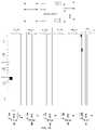
- FIG. 21shows 3 examples of routing Uplink signals over the network of DAUs and DRUs according to an embodiment of the present invention.
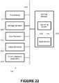
- FIG. 22is a high level schematic diagram illustrating a computer system according to an embodiment of the present invention.
- Wireless and mobile network operatorsface the continuing challenge of building networks that effectively manage high data-traffic growth rates.
- network operatorsattempt to provide networks that are available and functional in most locations where their clients will expect to be able to use their devices. This is a difficult task, as it is hard to determine how to geographically allocate resources, given the unpredictable nature of where and how users will wish to use their devices.
- Allocating network resourcesis complicated by users' mobility and unpredictability. For example, configuring a network to effectively allocate wireless network resources in an office building may present challenges (e.g., with regard to available wireless capacity and data throughput) if workers migrate from their offices to congregate in a cafeteria during lunch hours. Efficient resource allocation for work hours may provide poor coverage to users during lunch hours. To accommodate variations in wireless subscriber loading at wireless network antenna locations at various times of day and for different days of the week, there are several candidate conventional approaches.
- One approachis to deploy many low-power high-capacity base stations throughout the facility.
- the quantity of base stationsis determined based on the coverage of each base station and the total space to be covered.
- Each of these base stationsis provisioned with enough radio resources, i.e., capacity and broadband data throughput to accommodate the maximum subscriber loading which occurs during the course of the workday and work week.
- radio resourcesi.e., capacity and broadband data throughput to accommodate the maximum subscriber loading which occurs during the course of the workday and work week.
- this approachtypically yields a high quality of service for wireless subscribers
- the notable disadvantage of this approachis that many of the base stations' capacity is being wasted for a large part of the time. Since a typical indoor wireless network deployment involves capital and operational costs which are assessed on a per-subscriber basis for each base station, the typically high total life cycle cost for a given enterprise facility is far from optimal.
- a second candidate approachinvolves deployment of a distributed antenna system (DAS) along with a centralized group of base stations dedicated to the DAS.
- DASdistributed antenna system
- a conventional DAS deploymentfalls into one of two categories.
- the first type of DASis “fixed”, where the system configuration doesn't change based on time of day or other information about usage.
- the remote units associated with the DASare set up during the design process so that a particular block of base station radio resources is thought to be enough to serve each small group of DAS remote units.
- a notable disadvantage of this approachis that most enterprises seem to undergo frequent re-arrangements and re-organizations of various staff groups within the enterprise. Therefore, it's highly likely that the initial DAS setup will need to be changed from time to time, requiring deployment of additional direct staff and contract resources with appropriate levels of expertise regarding wireless networks.
- the second type of DASis equipped with a type of network switch which allows the location and quantity of DAS remote units associated with any particular centralized base station to be changed manually.
- this approachwould appear to support dynamic DAS reconfiguration based on the needs of the enterprise or based on time of day, it frequently implies that additional staff resources would need to be assigned to provide real-time management of the network.
- Another issueis that it's not always correct or best to make the same DAS remote unit configuration changes back and forth on each day of the week at the same times of day.
- the enterprise IT managerhas no practical way to determine the loading at a given time of day for each DAS remote unit; they can only guess the percentage loading.
- DAS deploymentsAnother major limitation of conventional DAS deployments is related to their installation, commissioning and optimization process. Some challenging issues which must be overcome include selecting remote unit antenna locations to ensure proper coverage while minimizing downlink interference from outdoor macro cell sites, minimizing uplink interference to outdoor macro cell sites, and ensuring proper intra-system handovers while indoors and while moving from outdoors to indoors (and vice-versa). The process of performing such deployment optimization is frequently characterized as trial-and-error. Therefore, the results may not be consistent with a high quality of service.
- Embodiments of the present inventionsubstantially overcome the limitations of the conventional approach discussed above.
- the advanced system architectureprovided by embodiments of the present invention provides a high degree of flexibility to manage, control, enhance and facilitate radio resource efficiency, usage and overall performance of the distributed wireless network.
- This advanced system architectureenables specialized applications and enhancements including, but not limited to, flexible simulcast, automatic traffic load-balancing, network and radio resource optimization, network calibration, autonomous/assisted commissioning, carrier pooling, automatic frequency selection, radio frequency carrier placement, traffic monitoring, and/or traffic tagging.
- Embodiments of the present inventioncan also serve multiple operators, multi-mode radios (modulation-independent) and multiple frequency bands per operator to increase the efficiency and traffic capacity of the operators' wireless networks.
- embodiments of theprovide a capability for Flexible Simulcast.
- the amount of radio resources(such as RF carriers, LTE Resource Blocks, CDMA codes or TDMA time slots) assigned to a particular DRU or group of DRUs can be set via software control to meet desired capacity and throughput objectives or wireless subscriber needs.
- Applications of the present inventionare suitable to be employed with distributed base stations, distributed antenna systems, distributed repeaters, mobile equipment and wireless terminals, portable wireless devices, and other wireless communication systems such as microwave and satellite communications.
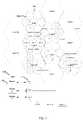
- FIG. 1is a diagram illustrating one wireless network system 100 that may provide coverage to a geographical area according to an embodiment of the present invention.
- System 100may include a distributed antenna system (DAS), which may efficiently use base-station resources.
- DASdistributed antenna system
- One or more base stations 105may be located in a central location and/or at a base station hotel.
- One or more base stations 105may include a plurality of independent outputs or radio resources, known as sectors 110 .
- Each sector 110may be responsible for providing wireless resources (e.g., RF carrier signals, Long Term Evolution Resource Blocks, Code Division Multiple Access codes, Time Division Multiple Access time slots, etc.).
- the resourcesmay include one or more resources that allow a wireless user mobile device to effectively and wirelessly send and receive communications over a network.
- the resourcesmay include one or more resources, such as those listed above, that allow a signal to be encoded or decoded in a manner to prevent the signal from interfering with or being interfered with by other wireless signals.
- Different sectorsmay be used to cover 3 separate geographical areas without creating co-channel interference between users in the distinct sectors.
- Each sectormay be coupled to a software-defined radio (SDR) (which may also be referred to as a software-configurable radio (SCR)) based digital access unit (DAU) 115 , which may interface sector 110 (and thus base station 105 ) with digital remote units (DRUs) 120 .
- the couplingmay represent a physical coupling.
- DAU 115may be connected to sector 110 and/or DRU 120 via a cable, a link, fiber, an RF cable, an optical fiber, an Ethernet cable, microwave line of sight link, wireless link, satellite link, etc.
- DAU 115is connected to sector 110 via an RF cable.
- DAU 115is connected to one or more DRUs via an optical fiber or Ethernet cable.
- An associated sector 110 and DAU 115may be located near each other or at a same location.
- DAU 115may convert one or more signals, such as optical signals, RF signals, digital signals, etc.
- DAU 115may include a multi-directional signal converter, such that, e.g., RF signals may be converted to optical signals and optical signals to RF signals, or to convert signals between a signal type associated with a sector and a signal type associated with a DRU.
- DAU 115converts a sector's downlink RF signals to optical signals, and/or converts a DRU's uplink optical signals to RF signals.
- DAU 115may also or alternatively control routing of data and/or signals between sectors and DRUs, as explained in greater detail below.
- DAU 115may generate and/or store traffic statistics, such as a number of communications, calls, network-access sessions, etc. between sector 110 and one or more DRUs 120 .
- Each DAU 115may be coupled to a plurality of digital remote units (DRUs) 120 .
- the plurality of DRUs 120may be coupled to the 115 through, e.g., a daisy-chain (indirectly coupling a DAU with one or more DRUs) and/or star configuration (directly coupling a DAU to multiple DRUs).
- a daisy-chainindirectly coupling a DAU with one or more DRUs
- star configurationdirectly coupling a DAU to multiple DRUs.
- FIG. 1shows an example of daisy-chain configurations, wherein a DAU couples to a first DRU directly (e.g., direct connection from DAU 1 to DRU 1 ), a second DRU indirectly (e.g., indirect connection from DAU 1 to DRU 2 through DRU 1 ), a third DRU indirectly (e.g., indirect connection from DAU 1 to DRU 3 through DRUs 1 and 2 ), etc.
- FIG. 1also shows an example of star configurations, wherein a DAU couples to multiple DRUs directly (e.g., direct connections from DAU 1 to DRU 1 and DRU 23 ). Each DRU can provide unique header information associated with each DRU which uniquely identifies uplink data received by that particular DRU.
- Each of the DRUscan provide coverage within a geographical area physically surrounding the DRU.
- DRUs 120may be strategically located to efficiently provide combined coverage across a larger geographical area (a “cell” 125 ).
- DRUs 120may be located along a grid, and/or coverage areas associated with adjacent DRUs 120 may be barely overlapping.
- a networkmay include a plurality of independent cells that span a total coverage area.
- Each cell 125may be assigned to a sector 110 .
- FIG. 1shows an embodiment in which Sector 1 provides resources to Cells 1 and 8 , Sector 2 to Cells 2 and 10 , and Sector 3 to Cells 3 and 4 .
- An associated sectormay provide each DRU with resources, such as RF carriers, resource blocks, etc.
- each of a plurality of sectors 110is associated with a set of “channels” or frequency ranges.
- the set of channels associated with each sector 110may be different from a set of channels associated with other sectors 110 in base station 105 .
- a networkmay be configured such that neighboring cells 125 are associated with different channels (e.g., by being associated with different sectors 110 ), as shown in FIG. 1 . This may allow channels to be reused across multiple cells without the risk of creating interference.
- each sector 110is connected to an associated subset of all of the DRUs in the network.
- Sector 1 's resourcese.g., assigned channels
- DRUs 120may be dynamically assigned to sectors 110 based on an interconnection between DAUs 115 (e.g., interconnected using PEER ports).
- DRUs 1 - 7 in Cell 1may initially all be assigned to Sector 1 .
- DRU 5may be assigned to Sector 3 and DRU 6 may be assigned to Sector 4 .
- signals to DRU 6may pass from Sector 2 through DAU 2 and through DAU 1 .
- signals to DRU 5may pass from Sector 3 through DAU 3 , through DAU 2 and through DAU 1 .
- a sectormay be indirectly connected with a larger subset of DRUs in a network or with all DRUs in a network. Communications between DAUs may be partly controlled by one or more servers 130 , as explained in greater detail below.
- DAUs 115may be physically and/or virtually connected.
- DAUs 115are connected via a cable or fiber (e.g., an optical fiber, an Ethernet cable, microwave line of sight link, wireless link, or satellite link).
- a plurality of DAUs 115are connected to a wireless network, which allows information to be transmitted from one DAU 115 to another DAU 115 and/or allows information to be transmitted from/to a plurality of DAUs 115 .
- DRUs 120can be interconnected in a manner to facility revisions in resource routing.
- a DRU 120 connected to a DAU 115 or sector 110can be connected two other DRUs 120 —one within a daisy-chain and another connected to another daisy-chain.
- a set of interconnected “mesh” DRUs 120can route signals between other DRUs (e.g., in different daisy-chains).
- One feature of embodiments of the present inventionis the ability to route Base Station radio resources among the DRUs or group(s) of DRUs. In order to route radio resources available from one or more Base Stations, it is desirable to configure the individual router tables of the DAUs and DRUs in the DAS network. This functionality is provided by embodiments of the present invention.
- router tablesare used to configure the networked DAUs.
- the local router tablesestablish the mapping of the inputs to the various outputs.
- Internal Merge blocksare utilized for the Downlink Tables when the inputs from an External Port and a PEER Port need to merge into the same data stream.
- Merge blocksare used in the Uplink Tables when the inputs from the LAN Ports and PEER Ports need to merge into the same data stream.
- the remote router tablesestablish the mapping of the inputs to the various outputs.
- Internal Merge blocksare utilized for the Downlink Tables when the inputs from a LAN Port and a PEER Port need to merge into the same data stream.
- Merge blocksare used in the Uplink Tables when the inputs from the External Ports and PEER Ports need to merge into the same data stream.
- a load-balancing systemmay include multiple base stations (or multiple base station hotels) 105 .
- the base stationsmay represent independent wireless network operators and/or multiple standards (WCDMA, LTE, etc.) or they may represent provision of additional RF carriers.
- the base station signalsmay be combined before they are connected to a DAU, as may be the case for a Neutral Host application.
- Different base stations 105may be associated with the same, overlapping, non-overlapping or different frequency bands.
- Base stations 105may be interconnected, e.g., to serve a geographic area.
- the interconnectionmay include a direct connection extending between the base stations (e.g., a cable) or an indirect connection (e.g., each base station connecting to a DAU, the DAUs being directly connected to each other).
- the greater number of base stationsmay increase the ability to add capacity for a given cell.
- Base stations 105may represent independent wireless network operators and/or multiple standards (WCDMA, LTE, etc.), and/or they may represent provision of additional RF carriers.
- base station signalsare combined before they are connected to a DAU, as may be the case for a Neutral Host application.
- sectors from BTS 1are directly coupled to the same DAUs and/or DRUs that are directly coupled to sectors to BTS N.
- one or more sectors from different BTSmay be directly coupled to DAUs not shared by sectors of one or more other DAUs.
- Load balancingmay or may not be applied differently to the different base stations 105 . For example, if DRU 5 is reassigned from Sector 1 to Sector 2 in BTS 1 , it may or may not be similarly reassigned in BTS N.
- the network of DRUsshould have the capability of re-directing their individual uplink and downlink signals to and from any of the BTS sectors. Because the DRUs data traffic has unique streams, the DAU Router has the mechanism to route the signal to different sectors.
- FIG. 5illustrates a method 500 of allocating network resources across a geographical region according to an embodiment of the invention.
- an initial usage mapmay be determined.
- the usage mapmay include an actual or predicted use per spatial unit (and/or per temporal unit).
- the spatial unitmay include: a Cell 125 , a geographical region associated to a DRU 120 , a sub-region in a Cell, or a sub-region within a geographical region associated with a DRU 120 . For example, it may be predicted that a large number of users will attempt to use the network between 3 PM-4 PM ET within Cell 1 .
- the mapmay also include an actual or predicted type of use (e.g., per-user bandwidth, per-spatial-unit bandwidth, whether the use is for a phone call or other data transmission, etc.).
- the spatial mapmay be generated to predict total requested resources across various spatial uses.
- the usage mapmay include an actual or predicted usage for each spatial/temporal unit on the map (e.g., each spatial unit within a network's coverage) or only a subset of the units. For example, in some embodiments, the map only includes predicted usages for spatial units predicted to be in high demand
- a usage mapmay be predicted in a variety of ways. For example, a system could monitor actual usage and detect temporal and spatial patterns, and/or a system could track devices associated with a network to identify where the devices are located (and thereafter predict that regions where many devices are located will receive many network requests). As another example, the map may be predicted based on common-sense habits (e.g., that fewer people will likely be in their offices in the evenings).
- a usage mapis determined, not based on a prediction, but based on currently or recently identified usage. For example, the map could identify the current number of users connected to the network in each of a plurality of spatial units.
- each of a plurality of DRUs 120may be assigned to one or more sectors 110 .
- the assignmentmay be determined based at least partly on the initial usage map determined at 505 , default assignments and/or at least partly on a network's architecture.
- one, more or all DRUs 120 in a networkmay have a default sector assignment.
- the default assignmentmay be determined based on a number of DAUs separating the DRU at issue from the sector at issue. For example, in FIG. 3 , DRU 4 would be separated from Sector 1 by 1 DAU, but from Sector 3 by 3 DAUs.
- the default assignmentmay be determined based on a test communication between the DRU at issue and the sector at issue.
- DRU 4could send a test communication with each sector requesting a response signal, and the sector providing the highest quality of service to the users may be assigned to the DRU.
- the quality of servicemay be evaluated by assessing, e.g., a maximum system throughput, a highest number of users that can be provided with basic service, a percentage of users for which a service at or surpassing a particular quality level is available, an average or median signal quality available to users and/or an average or minimum quality of signal available to a percentage (e.g., 51%, 80% or 90%) of users.
- the default assignmentmay be the same as the most recent assignment.
- Assignmentsmay also or alternatively depend on the determined usage map. For example, in one instance, it may be predicted that the default assignments would lead to substantially more use of Sector 1 's resources than the other sectors. One or more DRUs in Sector 1 may then be re-assigned to other sectors in an attempt to avoid this imbalance. In some instances, re-assignment always occurs to minimize resource imbalance. In some instances, re-assignment only occurs when a particular threshold (e.g., of imbalance or of resource requests sent to a sector) is or is predicted to be reached. In some instances, reassignment is at least partly or entirely determined based on other considerations, such as expected frequency interference, or predicted temporal variation in usage patterns, etc.
- the selection of the DRUs to be reassignedmay, for example, depend on: (1) determined use of an area associated with a DRU (e.g., re-assigning one or more DRUs associated with regions of the highest determined use, re-assigning one or more DRUs in an attempt to most evenly balance resource use, etc.); (2) maximizing the quality of service for the users in an area associated with a DRU; (3) cell association (e.g., attempting to cluster or avoid clustering of reassignments within select cells); (4) intra-cell location (e.g., attempting to re-assign DRUs associated with geographical locations that would be least likely to result in transmission interference following the assignment); and/or (5) whether the cell was recently re-assigned (e.g., attempting to maintain continuity between subsequent assignments).
- determined use of an area associated with a DRUe.g., re-assigning one or more DRUs associated with regions of the highest determined use, re-assign
- one or more DRUsis assigned to a plurality of sectors.
- a DRUmay always be assigned to a default sector (e.g., one separated by the fewest number of DAUs).
- the DRUmay also be assigned to another sector based on analysis of the determined usage map. This analysis may include, e.g., any of the considerations presented above with regard to re-assignment considerations.
- DRU assignmentsmay include weights (e.g., indicating the percentage of a DRU's usage load that should be handled by each assigned sector).
- the assignmentsmay be stored.
- the assignmentsmay be stored in a database, e.g., at a central server 130 .
- the databasemay include time periods, spatial regions, DRU identifiers, and/or sector identifiers.
- the databasemay indicate that from 10 AM-12 PM on Monday, DRUs 1 - 7 are assigned to sector 1 , DRUs 8 - 14 are assigned to sector 2 , etc.
- the assignmentsare general assignments. For example, after learning about usage patterns, a system may develop day- and time-dependent assignments for all DRUs in a network, which may be completely or substantially static. As another example, assignments are repeatedly re-determined. For example, assignments may be based partly or completely on currently or recently observed usage.
- a networkis virtually configured based on the assignments.
- the configuringmay allow select network components to be coupled (e.g., assigned sectors and DRUs) without requiring manipulating the network architecture or hardware.
- indicationsmay be sent to one or more DAUs 115 (e.g., over a wireless network or over a physical connection to the one or more DAUs) to indicate how the DAU should route received signals (e.g., downlink and/or uplink signals) and/or allocate sector resources.
- a DAU 115may be instructed to send signals from a DRU 120 directly to a sector and/or to another DAU 115 .
- a DAU 115may be instructed to send signals from a sector directly to a DRU 120 and/or to another DAU 115 .
- a signal received from or sent to a DRUmay be encoded to allow for identification of the DRU (e.g., by encoding the DRU identity in a signal header, or by time division multiplexing the DRU signals), thereby allowing a DAU to determine how to route the signal.
- a signal received from or sent to a sectormay be encoded to allow for identification of the sector (e.g., by encoding the sector identity in a signal header), thereby allowing a DAU to determine how to route the signal.
- the indicationsprovide one or more DAUs with instructions as to particular DRUs that are to be supplied power from particular sectors.
- a new usage mapmay be determined. For example, a new usage map may be determined at regular intervals (e.g., once an hour), when the sectors' resources are being unevenly used, when the use of one or more sectors' resources exceeds a threshold, etc.
- the new usage mapmay be determined in any of the ways as described above with respect to 505 .
- the initial and new usage mapsmay be determined using the same, similar or different techniques.
- DRUsare assigned to one or more sectors.
- the assignmentsmay be completely new with respect to the assignments made at 510 or may include modifications of the assignments.
- the assignmentsmay be made in any of the ways as described above with respect to 510 .
- Assignment techniquesmay be the same, similar or different for the assignments at 510 and at 530 .
- the assignments at 530may also or alternatively be based on geographical discrepancies in usage.
- both assignmentsare based on usage maps.
- at least some assignments at 530are different from corresponding assignments at 510 .
- one or more DRUsmay be assigned to a sector separated by the fewest number of DAUs from the respective DRU in 510 , while the same one or more DRUs may be assigned to another sector in 530 (e.g., to allow a more even distribution of use among sectors).
- the assignmentsare stored.
- the assignmentsmay be stored in a database, e.g., at a central server 130 .
- the databasemay include time periods, spatial regions, DRU identifiers, and/or sector identifiers.
- the assignmentsmay be stored in a same database as one storing assignments at 515 .
- the assignmentsmay replace previously stored assignments, or multiple sets of assignments may be stored. For example, each assignment set may be associated with a unique identifier, an iteration count, a time period, a trigger, etc.
- the stored assignmentsmay include a complete assignment set (e.g., assigning each of all of the DRUs in a network to one or more sectors) or a partial assignment set. For example, assignments may only be stored if an assignment differs from a previous assignment or from a default assignment.
- the network that was configured at 520is virtually re-configured based on the assignments.
- the networkmay be re-configured in any manner as described with respect to 520 .
- the networkis configured at 520 and re-configured at 540 in the same way.
- the re-configuringis more efficient (e.g., only re-configuring elements that are changed based on the new assignments).
- the networkis only re-configured if the assignments at 530 differ from those at 510 .
- the processmay involve repeating one or more features.
- 525 - 540may be repeated, e.g., at regular time intervals or upon detecting a condition (e.g., network imbalance, above-threshold sector use, etc.).
- a conditione.g., network imbalance, above-threshold sector use, etc.
- FIG. 6illustrates a method 600 of routing a DRU signal according to an embodiment of the invention.
- a signal that originated at a DRUmay be received (e.g., at a DAU).
- the signalmay or may not be received directly from the DRU.
- the signalmay have been passed from a source DRU through one or more other DRUs and/or through one or more DAUs.
- the signalmay be received via an optical-fiber transmission, Ethernet cable, etc.
- the signalmay include, e.g., an optical signal or digital signal.
- the signalmay be decoded to identify the DRU at which the signal originated (i.e., the source DRU).
- This identificationmay include identifying one of a plurality of DRUs.
- the identificationmay include analyzing a header of the received signal, which may, e.g., include an identifier corresponding to the source DRU, or by time division multiplexing the DRU signals.
- a DRUmay receive a signal from a cell phone and convert/encode the signal such that the converted/encoded signal may be transmitted to a base station in a network.
- the DRUmay further augment the converted/encoded signal with a header identifying the DRU, or by time division multiplexing the DRU signals. This augmented signal may then be transmitted to a connected DAU.
- the routingmay indicate, e.g., a final destination sector and/or an immediate routing. For example, in one instance, the routing may indicate that a signal from DRU 7 is to be routed to Sector 2 . A DAU that received the signal may then determine how to route the signal based on the relative network location of the DAU and the final sector destination (e.g., whether the DAU is connected to the sector, or other DAUs that separate the DAU from the sector). In one instance, the routing may indicate that a signal from DRU 7 received at DAU 1 is to be routed to a downstream DAU or to DAU 2 .
- the signalmay be converted.
- the signalmay be converted from a signal type sent by DRUs to a signal type that may be received by sectors.
- the signalmay be converted from an optical or digital signal to an RF signal.
- the signalis not converted.
- the signalis only converted when it is received from a DRU (not from a DAU) or when it is to be routed directly to a sector (not to a DAU).
- the signalmay be routed in accordance with the determined routing.
- the signalmay be routed, e.g., to one or more connected network components, such as a connected DAU and/or connected sector.
- FIG. 7illustrates another method 700 of routing a DRU signal according to an embodiment of the invention.
- FIG. 7 's 705 - 720parallel FIG. 6 's 605 - 620 .
- FIG. 7 's 705 - 720parallel FIG. 6 's 605 - 620 .
- the determined routingmay include identifying one or more destination sectors, which are to receive the signal.
- itmay be determined whether a network component (e.g., a DAU) that received the signal at 705 is directly connected to all destination sectors. For example, it may be determined whether the DAU is directly connected via cable or fiber to all destination sectors and/or whether the DAU is connected to all destination sectors without any intermediate DAUs. If it is determined that the network component is directly connected to all destination sectors, the signal may be sent to the directly-connected destination sector(s) at 730 .
- a network componente.g., a DAU
- the signalmay be sent to a connected DAU at 735 .
- the signalis sent to a particular DAU (e.g., identified at 715 ).
- the signalis sent to all DAUs directly connected to a network component (e.g., DAU) that received the signal at 705 .
- the signalis sent to a directly connected DAU that is categorized as being upstream or downstream from a network component (e.g., DAU) that received the signal at 705 .
- itmay then be determined whether the network component (e.g., a DAU) that received the signal at 705 is directly connected to at least one destination sector. If so, the signal may then be sent to the directly connected destination sector(s) at 730 . Otherwise, process 700 may end with respect to the signal received at 705 .
- the network componente.g., a DAU
- FIG. 8illustrates a method 800 of routing a sector signal according to an embodiment of the invention.
- a signale.g., a downlink RF signal
- the signalmay or may not be received directly from the sector.
- the signalmay have been passed from a source sector through one or more DAUs.
- the signalmay be received via an RF cable transmission.
- the signalmay be decoded to identify a destination DRU (e.g., a DRU that is to receive the signal).
- This identificationmay include identifying one of a plurality of DRUs.
- the identificationmay include analyzing a header of the received signal, which may, e.g., include an identifier corresponding to the source DRU, or by time division multiplexing the DRU signals.
- Each DASmay receive resources (e.g., RF carriers, Long Term Evolution Resource Blocks, Code Division Multiple Access codes or Time Division Multiple Access time slots) from a central base station including a plurality of sectors and distribute the resources to a plurality of digital remote units (DRUs). Routing tables in the DAUs and DRUs may be configured to identify where the signals will be routed.
- the routingmay indicate, e.g., a final destination DRU and/or an immediate routing. For example, in one instance, the routing may indicate that a signal from Sector 2 may reach DRU 7 by transmitting the signal from DAU 2 to DAU 1 (which may then transmit the signal to reach DRU 7 ). In one instance, the routing may indicate that a signal from Sector 1 may reach DRU 7 by transmitting the signal from DAU 1 to DRU 1 (which may then transmit the signal to reach DRU 7 ).
- the signalmay be converted.
- the signalmay be converted from a signal type sent by sectors to a signal type that may be received by DRUs.
- the signalmay be converted from an RF signal to an optical signal.
- the signalis not converted.
- the signalis only converted when it is received from a DRU (not from a DAU) or when it is to be routed directly to a sector (not to a DAU).
- the signalmay be routed in accordance with the determined routing.
- the signalmay be routed, e.g., to one or more connected network components, such as a connected DAU and/or connected DRU.
- FIG. 9illustrates another method 900 of routing a sector signal according to an embodiment of the invention.
- FIG. 9 's 905 - 915parallel FIG. 8 's 805 - 810 and 820 .
- a network entitye.g., a DRU
- the signalmay be sent to the identified DRU recipient at 925 .
- the signalmay be sent to the DRU directly or to another DRU that is daisy-chained to the recipient DRU.
- the signalmay be sent to a connected DAU at 930 .
- the signalis sent to all DAUs connected to a network entity that received the signal at 905 .
- the network entity, or a server coupled theretoselects a DAU to which the signal is to be sent based on a path separating the network entity from the recipient DRU.
- a routing databaseindicates which DAU the signal is to be sent to, given a source and/or destination of the signal.
- Dynamic assignments of DRUs to one or more sectorsmay lead to circumstances in which an assignment of a DRU during a first time period is different from an assignment of a DRU during a second, subsequent time period.
- a variety of techniquesmay be used to transition from the first assignment to the second assignment.
- the transitionincludes a hard hand off, in which the first assignment completely changes to the second assignment at a particular point in time.
- This transition timemay include, e.g., upon determination of the second assignments, at a beginning of a time period associated with the second assignments, etc.
- the transitionincludes a modified hard hand off.
- the assignmentmay change as described above with respect to the hard hand off (e.g., at a particular time), but the transition may be modified in an attempt to avoid dropping calls. For example, signals associated with any calls on-going at the time of the transition may retain the first assignment, while any calls initiated after the transition may be associated with the second assignment.
- the transitionincludes a soft hand off, which may decrease the probability of dropping calls and/or data sessions in progress at a transition time.
- the soft transitionmay include identifying DRUs assigned to sectors different than a previous assignment, and determining a transition assignment for each DRU, wherein the transition assignment comprises an assignment to both an old and a new sector.
- the soft transitionmay include a duplicative unweighted transition. For example, if DRU 6 was previously assigned to Sector 1 and later assigned to Sector 2 , signals could be transmitted from/to both sectors for an intermediate time period.
- the time periodmay or may not be fixed. For example, the time period may be seconds or the time period may be until the newly assigned sector has indicated that it has properly begun to receive/send signals.
- the transitionincludes a partial hand off.
- the partial transitionmay include identifying DRUs assigned to sectors different than a previous assignment, and determining a new assignment for each DRU, wherein the new assignment comprises an assignment to both an old and a new sector.
- the partial hand-off transitionneed not be temporary and can instead be maintained for a period of time or indefinitely. Signals may be transmitted from/to both the previous and new DRU at equal and/or full weights or the signals may be weighted.
- the partial hand-off transitionmay be advantageous, e.g., if a DRU is physically located near or at a sector's boundary.
- the transitionincludes a weighted soft hand off.
- the soft transitionmay gradually decrease weighting of signals received from/to one or more sectors initially assigned to a DRU and/or increasing weighting of signals received from/to one or more sectors subsequently assigned to the DRU.
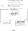
- FIG. 10illustrates a method 1000 of transitioning between subsequent DRU-sector assignments.
- a DRUmay be assigned to one or more first sectors.
- the assignmentmay be made using any of the techniques described herein.
- the assignmentmay be based at least partly on default assignments and/or actual or predicted geographic use patterns.
- the DRUmay be provided with a resource from the assigned one or more first sectors.
- Each DRUmay receive resources (e.g., RF carriers, Long Term Evolution Resource Blocks, Code Division Multiple Access codes or Time Division Multiple Access time slots) from a central base station including a plurality of sectors and distribute the resources to a plurality of digital remote units (DRUB).
- a resource associated with a sectore.g., a frequency channel
- the resourcemay be provided via connections (e.g., an RF connections, optical connection, digital connection, etc.) between the one or more first sectors and the DRU (e.g., via one or more DAUs).
- the DRUmay be assigned to one or more second sectors.
- the assignmentmay be made using any of the techniques described herein. For example, the assignment may be based partly on default assignments and/or actual or predicted geographic use patterns.
- the first and second assignmentsmay be made using the same or different techniques.
- the DRUmay be provided with the resource from the one or more second sectors at 1025 (e.g., as described with respect to 1010 ).
- a soft hand-offmay be performed at 1030 between the first and second sector(s).
- the resourcemay gradually shift from being supplied by the first sector(s) to being supplied by the second sector(s).
- the second sector(s)may receive an increasing amount of resource power from the DRU or an increasing number of frequency bands, while the first sector(s) may correspondingly receive a decrease in resource power.
- Mobile devices in an area surrounding the DRUmay then detect a decreasing signal strength from the first sector(s) and switch any on-going communications to connect with the increasingly strong second sector(s). Thus, the mobile devices may then begin to second-sector resources as opposed to first-sector resources.
- the processmay then repeat 1015 - 1030 , continually re-assigning the DRU, determining whether the newly assigned sector(s) differ from the previously assigned sector(s), and appropriately adjusting resource supplies in view of the determination.
- Soft hand-offs between sectorsmay protect the network from dropping communications or calls, while simultaneously efficiently allocating resources (to improve data rates and decrease interference).
- FIG. 11is a diagram illustrating a wireless network system 1100 using a soft-hand-off.
- DRU 5is newly assigned to Sector 3
- DRU 6is newly assigned to Sector 2 . Both DRU 5 and DRU 6 were previously assigned to Sector 1 .
- signals from DRUs 1 - 7may be initially routed to DAU 1 .
- DAU 1may then determine how to route the signals by, e.g., any of the above-described techniques.
- DAU 1may identify transition assignments, based on the new assignments of DRUs 5 and 6 .
- the transition assignmentsmay include assignments to multiple sectors, each being associated with a gain factor (affecting an uplink or downlink path connectivity).
- DRU 1may gradually increase a gain of signals sent from DRUs 5 and 6 to DAU 2 (to thereafter send to Sector 2 or to DAU 3 to send to Sector 3 ), and/or DRU 1 may gradually decrease a gain of signals sent from DRUs 5 and 6 to Sector 1 .
- the increase and decreasemay be complementary, such that, e.g., a total gain of the DAU 5 - 6 signals (sent either to Sector 1 or to DAU 2 ) remains substantially or completely constant.
- the gainmay vary, e.g., over a time period of about 1-60 seconds or about 1-5 minutes. Relatively short transition periods may improve network efficiency.
- DAUsmay similarly adjust gains of signals received from sectors.
- DAU 1may receive a signal from Sector 1 for DRU 6 and from Sector 2 (via DAU 2 ) for DRU 6 .
- DAU 2may then adjust the gain of these signals (and, in some instances, combine the signals), and send the signal(s) to DRU 6 (via DRUs 1 - 5 ).
- the gain of the signal from Sector 2is adjusted at DAU 2 instead of DAU 1 .
- gain coefficientsare determined and/or stored for all DRU-Sector pairs in a network.
- the gainmay be set to zero or one when no transition is in effect.
- gain coefficientsare only determined and/or stored for a subset of DRU-Sector pairs in a network. For example, they may only be determined for DRUs that have been assigned to one or more different sectors, as compared to a previous respective assignment.
- FIG. 12illustrates components of a DAU 1150 according to an embodiment of the invention.
- DAU 1150may include a router (i.e., Local Router 1205 ).
- DAU 1150may include one or more ports 1215 and 1220 .
- Ports 1215 and 1220may, e.g., enable DAU to connect to the Internet and/or a Host Unit or a server 1225 (e.g., Server 130 ).
- Server 1225may at least partly configure the DAU and/or control the routing of the signals between various Local Router ports.
- Server 1225may be, e.g., at least partly controlled by a remote operational control 1230 (e.g., to set re-assignment conditions, identify assignments, store assignments, input network configurations, receive/collect/analyze network usage, etc.).
- a remote operational control 1230e.g., to set re-assignment conditions, identify assignments, store assignments, input network configurations, receive/collect/analyze network usage, etc.
- DAU 1150may include one or more physical nodes 1210 , which may be coupled to Local Router 1205 by one or more first-end ports 1235 .
- the physical nodes 1210may translate the RF signals to baseband for the Downlink and from baseband to RF for the Uplink.
- the physical nodes 1210may connect to the BTS at radio frequencies (RF).
- RFradio frequencies
- the physical nodes 1210can be used for different operators, different frequency bands, different channels, or the like.
- the physical nodes 1210can combine the downlink and uplink signals via a duplexer or they can keep them separate, as would be the case for a simplex configuration.
- the physical node 1210can translate the signals from RF to baseband for the downlink path and from baseband to RF for the uplink path.
- Each physical node 1210may include one, two, or more ports, such as first-end ports, each of which may allow signals (e.g., RF signals and/or signals from/to a sector) to be received by or transmitted from DAU 1150 .
- a plurality of physical nodes 1210each includes a Downlink port 1212 and an Uplink port 1213 .
- a physical node 1210may also include an additional Uplink port, e.g., to handle a diversity connection.
- Output portse.g., Downlink port 1212 and Uplink port 1213
- DAU 1150may be physically coupled to a base station.
- the Local Router 1205directs the traffic between the various LAN Ports, PEER Ports and the External Ports.
- Local Router 1205may include one or more second-end ports 1240 , which may couple DAU 1150 to one or more DRUs or DAUs e.g., via an optical fiber, Ethernet cable, etc.).
- the second-end ports 1240may include LAN or PEER ports.
- Second-end ports 1240may be configured to send and/or receive signals, such as digital and/or optical signals.
- the router 1205can direct the uplink data stream from the LAN and PEER ports to the selected External U ports. Similarly, the router 1205 can direct the downlink data stream from the External D ports to the selected LAN and PEER ports.
- At least one second-end port 1240couples DAU 1150 to another DAU, and at least one second-end port 1240 couples DAU 1150 to a DRU.
- the local routermay encode signals for transportation over the optical link as well as decodes the optical signals from the optical link.
- Physical Nodesmay perform the function of translating the RF signals to baseband or translating the baseband signals to RF.
- the DAUcan monitor traffic on the various ports and either route this information to a server or store this information locally.
- FIG. 13illustrates components of a DRU 1300 according to an embodiment of the invention.
- DRU 1300may include a router (i.e., Remote Router 1305 ).
- DRUmay include a network port 1310 , which may allow DRU 1300 to couple (via an Ethernet Switch 1315 ) to a (e.g., wireless) network. Through the network, DRU 1300 may then be able to connect to a computer 1320 . Thus, a remote connection may be established with DRU 1300 .
- a routeri.e., Remote Router 1305
- DRUmay include a network port 1310 , which may allow DRU 1300 to couple (via an Ethernet Switch 1315 ) to a (e.g., wireless) network. Through the network, DRU 1300 may then be able to connect to a computer 1320 . Thus, a remote connection may be established with DRU 1300 .
- Remote Router 1305may be configured by a server, such as server 130 , server 1225 , a server connected to one or more DAUs, and/or any other server. Router 1305 can direct the downlink data stream from the LAN and PEER ports to selected External D ports. Similarly, router 1305 can direct the uplink data stream from the External U ports to selected LAN and PEER ports. Network port 1310 may be used as a Wireless access point for connection to the Internet. The Internet connection may, e.g., established at the DAU and Internet traffic may be overlaid with the data transport between the DRUs Physical Nodes and the DAU Physical Nodes.
- DRU 1300may include one or more physical nodes 1325 .
- Physical nodes 1325can be used for different operators, different frequency bands, different channels, etc.
- Physical nodes 1325can translate the signals from RF to baseband for the uplink path and from baseband to RF for the downlink path.
- Each physical node 1325may include one, two, or more ports, such as first-end ports 1330 , each of which may allow for signals (e.g., RF signals and/or signals from mobile devices) to be received by or transmitted from DRU 1200 .
- a plurality of physical nodes 1325each include one or more ports configured to send/receive signals (e.g., RF signals) from/to DRU 1300 .
- the portsmay include, e.g., a Downlink port 1327 and an Uplink port 1328 .
- an additional Uplink portexists for handling a diversity connection.
- Physical node portse.g., Downlink output port 1327 and Uplink output port 1328
- Remote Router 1305may include one or more second-end ports 1335 , which may couple DRU 1300 to one or more DAUs or DRUs.
- Second-end ports 1335may include LAN or PEER ports, which may (e.g., physically) couple DRU 1300 to one or more DAUs or DRUs via an optical fiber.
- FIGS. 5 - 10provide particular methods according to an embodiment of the present invention. Other sequences of steps may also be performed according to alternative embodiments. For example, alternative embodiments of the present invention may perform the steps outlined above in a different order. Moreover, the individual steps illustrated in FIGS. 5 - 10 may include multiple sub-steps that may be performed in various sequences as appropriate to the individual step. Furthermore, additional steps may be added or removed depending on the particular applications. One of ordinary skill in the art would recognize many variations, modifications, and alternatives.
- FIG. 14depicts a DAS network that includes multiple DAUs and multiple DRUs.
- the Local Routersare shown in a Daisy Chain configuration.
- the Remote Routersare shown in a star and daisy chain configuration.
- the local routers in the DAUscan be interconnected via a PEER port.
- the Local routerscan connect to the remote routers in the DRUs via an optical or copper connection.
- the remote routers in the DRUscan be connected in a daisy chain configuration with other DRUs or they may be connected with a local router via a star configuration.
- the PEER ports in a DAUare used when there is no direct connection between a physical node connected to a local router's DAU and a physical node connected to a remote router DRU.
- PEER ports at the DRUare used for daisy chaining between two or more DRUs.
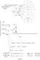
- FIG. 15shows how the data stream of the downlink ( 1500 ) and uplink ( 1501 ) can be serialized for transportation between DAUs, DRUs and between DAU to DRU.
- the datais streamed using a protocol such as CPRI.
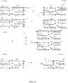
- FIG. 16provides the details of one embodiment of the Local Routers.
- the local routerincludes External Downlink and Uplink ports. It also includes LAN ports and PEER ports.
- the LAN portsare used to connect with DRUs on the network.
- the PEER portsare used to connect to other DAUs on the network.
- the Local Router Downlink tableis used to establish the routing of the data traffic between the inputs and the outputs.
- the blacked out squaresindicate a routing path.
- the External downlink input port 1 Dis routed to the MERGE input 1 of Merge block ⁇ and the PEER Port 1 input is routed to MERGE input 2 of Merge block ⁇ .
- the MERGE Port output of block ⁇is sent to LAN Port 1 stream AA.
- FIG. 16shows one embodiment where there are 5 Merge blocks and 5 streams.
- the Local Router tablewould be configured for a given network of DAUs and DRUs.
- the router tabledemonstrates the routing of the Downlink signals between the External D ports to the LAN/PEER ports.
- the tablecan easily be extended to additional Merge blocks, additional External Inputs, additional LAN ports and additional PEER ports.
- the MERGE blockscan also have multiple inputs.
- the tablecan have multiple blacked out squares within a row but can have only one blacked out square within a column.
- FIG. 17provides the details of one embodiment of the Local Routers.
- the local routerincludes External Downlink and Uplink ports. It also includes LAN ports and PEER ports.
- the LAN portsare used to connect with DRUs on the network.
- the PEER portsare used to connect to other DAUs on the network.
- the Local Router Uplink tableis used to establish the routing of the data traffic between the inputs and the outputs.
- the blacked out squaresindicate a routing path.
- the LAN port 1 input of stream AAis routed to the MERGE input 1 of Merge block ⁇ .
- the PEER Port 1 input of stream AAis routed to Merge input 2 of Merge block ⁇ .
- the output of Merge block ⁇is routed to external port 1 U.
- FIG. 17shows an embodiment of the Local Router table for the Uplink signals.
- the Local Router tablewould be configured for a given network of DAUs and DRUs.
- the router tabledemonstrates the routing of the Uplink signals between the LAN/PEER ports and the External U ports.
- FIG. 17shows one embodiment where there are 5 Merge blocks and 5 streams.
- the tablecan easily be extended to additional Merge blocks, additional External Inputs, additional LAN ports and additional PEER ports.
- the MERGE blockscan also have multiple inputs.
- the tablecan have multiple blacked out squares within a column but can have only one blacked out square within a row.
- FIG. 18provides the details of one embodiment of the Remote Routers.
- the remote routerincludes External Downlink and Uplink ports. It also includes LAN ports and PEER ports.
- the LAN portsare used to connect with DAUs on the network.
- the PEER portsare used to connect to other DRUs on the network.
- the Remote Router Downlink tableis used to establish the routing of the data traffic between the inputs and the outputs.
- the blacked out squaresindicate a routing path.
- the LAN port 1 input of stream AAis routed to the MERGE input 1 of Merge block ⁇ .
- the PEER Port 1 input of stream AAis routed to Merge input 2 of Merge block ⁇ .
- the output of Merge block ⁇is routed to external port 1 D.
- FIG. 18shows one embodiment where there are 5 Merge blocks and 5 streams.
- the tablecan easily be extended to additional Merge blocks, additional External Inputs, additional LAN ports and additional PEER ports.
- the MERGE blockscan also have multiple inputs.
- the tablecan have multiple blacked out squares within a column but can have only one blacked out square within a row.
- FIG. 18shows an embodiment of the Remote Router table for the downlink signals.
- the Remote Router tablewould be configured for a given network of DAUs and DRUs.
- the router tabledemonstrates the routing of the Downlink signals between the LAN/PEER ports and the External D ports.
- FIG. 19provides the details of one embodiment of the Remote Routers.
- FIG. 19shows an embodiment of the Remote Router table for the uplink signals.
- the Remote Router tablewould be configured for a given network of DAUs and DRUs.
- the router tabledemonstrates the routing of the Uplink signals between the External U ports and the LAN/PEER Ports.
- the remote routerincludes External Downlink and Uplink ports. It also includes LAN ports and PEER ports.
- the LAN portsare used to connect with DAUs on the network.
- the PEER portsare used to connect to other DRUs on the network.
- the Remote Router Uplink tableis used to establish the routing of the data traffic between the inputs and the outputs.
- the blacked out squaresindicate a routing path. As an example, in FIG.
- FIG. 19shows one embodiment where there are 5 Merge blocks and 5 streams.
- the tablecan easily be extended to additional Merge blocks, additional External Inputs, additional LAN ports and additional PEER ports.
- the MERGE blockscan also have multiple inputs.
- the tablecan have multiple blacked out squares within a row but can have only one blacked out square within a column.
- FIG. 20provides some examples of the routing of traffic through one embodiment of the network.
- operational codeis used to configure the local and remote routers.
- FIG. 21shows 3 examples of routing Downlink signals over the network of DAUs and DRUs. The tables demonstrate an embodiment of an operational code that could be used to set each of the Router tables.
- the downlink data input S 1 at External Port 1 D of Local Router Ais routed to the External Port 1 D of Remote router M.
- LAN Port 1is used to stream the data between the Local router A and the Remote router M.
- the downlink data input S 2 at External Port 2 D of Local Router Ais routed to the External Port 2 D of Remote router P.
- PEER Port M of Local router Ais used to stream the downlink signal S 2 to PEER port 1 of Local router B.
- LAN Port 3stream BB is used to communicate with LAN port 1 of Remote router P.
- the input of LAN Port 1 stream BBis routed to External Port 2 D in Remote router P.
- the downlink data input S 1 at External Port 1 D of Local Router Ais routed to the PEER Port M stream AA.
- the output from PEER Port M, stream AA of Local Router Ais input to PEER Port 1 of Local Router B.
- PEER Port 1 , stream AA of Local Router Bis sent to input 1 of Merge block ⁇ .
- the downlink data input S 3 at External Port 1 D of Local Router Bis routed to input 2 of Merge block ⁇ .
- the output of Merge block ⁇is routed to LAN Port 2 , stream AA of Local router B.
- LAN Port 2 , of Local Router Btransports data to LAN Port 1 of Remote Router O.
- the input data from LAN Port 2 , of Remote Router Ois routed to External Port 1 D.
- FIG. 21provides some examples of the routing of traffic through one embodiment of the network.
- operational codeis used to configure the local and remote routers.
- FIG. 22shows 3 examples of routing Uplink signals over the network of DAUs and DRUs. The tables demonstrate an embodiment of an operational code that could be used to set each of the Router tables.
- the Uplink data input S 3 at External Port 1 U of Remote Router Ois routed to LAN Port 1 .
- LAN Port 1 , stream AA of Remote Router Ois used to stream the data between LAN Port 1 , stream AA of Remote router O and LAN Port 2 , Stream AA of Local router B.
- the input to LAN Port 2 , stream AA of Local router Bis routed to external Port 1 U.
- the uplink data input S 4 at External Port 2 U of Remote Router Pis routed to LAN Port 1 , stream BB of Remote router P.
- LAN Port 1 , stream BB of Remote router Pis used to stream the uplink signal S 4 to LAN port 3 , stream BB of Local router B.
- LAN Port 3 , stream BBis routed to PEER port 1 , stream BB of Local router B.
- PEER Port 1 , stream BB of Local router Btransports data to LAN Port M, stream BB of Local router A.
- the input of PEER Port 1 stream BBis routed to External Port 2 U in Local router A.
- the uplink data input S 2 at External Port 1 U of Remote Router Nis routed to the PEER Port 1 , stream AA of Remote router N.
- the output from PEER Port 1 , stream AA of Remote Router Nis input to PEER Port M of Remote Router M.
- PEER Port M, stream AA of Remote Router Mis sent to input 1 of Merge block ⁇ .
- the uplink data input S 1 at External Port 1 U of Remote Router Mis routed to input 2 of Merge block ⁇ .
- the output of Merge block ⁇is routed to LAN Port 1 , stream AA of Remote router M.
- LAN Port 1 , of Remote Router Mtransports data to LAN Port 1 of Local Router A.
- the input data from LAN Port 1 , of Local Router Ais routed to External Port 1 U of Local router A.
- Methods shown in FIG. 5 - 10 or elsewhere describedmay be performed by a variety of devices or components. For example, some processes may be performed solely or partly by one or more DAUs. Some processes may be performed solely or partly by a remote computer, e.g., coupled to one or more DAUs. Some processes may be performed by one or more DRUs. In some embodiments, shown or described process may be performed by multiple devices or components (e.g., by multiple DAUs, by one DAU and a remote server, by one or more DRUs and a DAU, etc.).
- embodimentsmay be implemented with, e.g. distributed base stations, distributed antenna systems, distributed repeaters, mobile equipment and wireless terminals, portable wireless devices, and/or other wireless communication systems such as microwave and satellite communications.
- distributed base stationsdistributed antenna systems, distributed repeaters, mobile equipment and wireless terminals, portable wireless devices, and/or other wireless communication systems such as microwave and satellite communications.
- embodiments including a single base stationmay be applied in systems including multiple, interconnected base stations.
- Embodimentsmay be modified to replace daisy-chain configurations with star configurations or the converse.
- Embodiments showing a single servere.g., connected to a plurality of DAUs
- Embodiments hereinallow for loads to be balanced across base station sectors. Finite base station resources may then be repeatedly redistributed across geographical areas, so as to efficiently provide coverage to a large area.
- the load balancingmay also protect base station sectors from overload and excess resource taxation upon a large accumulation of wireless users within a small number of cells (e.g., many users congregating at an enterprise lunch room at lunchtime or users congregating on a highway during rush hour).
- FIG. 22is a high level schematic diagram illustrating a computer system 2200 including instructions to perform any one or more of the methodologies described herein.
- One or more of the above-described componentsmay include part or all of computer system 2200 .
- System 2200may also perform all or part of one or more methods described herein.
- FIG. 22is meant only to provide a generalized illustration of various components, any or all of which may be utilized as appropriate. FIG. 22 , therefore, broadly illustrates how individual system elements may be implemented in a relatively separated or relatively more integrated manner.
- the computer system 2200is shown comprising hardware elements that can be electrically coupled via a bus 2205 (or may otherwise be in communication, as appropriate).
- the hardware elementsmay include one or more processors 2210 , including without limitation one or more general-purpose processors and/or one or more special-purpose processors (such as digital signal processing chips, graphics acceleration processors, and/or the like); one or more input devices 2215 , which can include without limitation a mouse, a keyboard and/or the like; and one or more output devices 2220 , which can include without limitation a display device, a printer and/or the like.
- the computer system 2200may further include (and/or be in communication with) one or more storage devices 2225 , which can comprise, without limitation, local and/or network accessible storage, and/or can include, without limitation, a disk drive, a drive array, an optical storage device, solid-state storage device such as a random access memory (“RAM”) and/or a read-only memory (“ROM”), which can be programmable, flash-updateable and/or the like.
- RAMrandom access memory
- ROMread-only memory
- Such storage devicesmay be configured to implement any appropriate data stores, including without limitation, various file systems, database structures, and/or the like.
- the computer system 2200might also include a communications subsystem 2230 , which can include without limitation a modem, a network card (wireless or wired), an infrared communication device, a wireless communication device and/or chipset (such as a BluetoothTM device, an 802.11 device, a WiFi device, a WiMax device, cellular communication facilities, etc.), and/or the like.
- the communications subsystem 2230may permit data to be exchanged with a network (such as the network described below, to name one example), other computer systems, and/or any other devices described herein.
- the computer system 2200will further comprise a working memory 2235 , which can include a RAM or ROM device, as described above.
- the computer system 2200also can comprise software elements, shown as being currently located within the working memory 2235 , including an operating system 2240 , device drivers, executable libraries, and/or other code, such as one or more application programs 2245 , which may comprise computer programs provided by various embodiments, and/or may be designed to implement methods, and/or configure systems, provided by other embodiments, as described herein.
- an operating system 2240device drivers, executable libraries, and/or other code
- application programs 2245may comprise computer programs provided by various embodiments, and/or may be designed to implement methods, and/or configure systems, provided by other embodiments, as described herein.
- code and/or instructionscan be used to configure and/or adapt a general purpose computer (or other device) to perform one or more operations in accordance with the described methods.
- a set of these instructions and/or codemight be stored on a computer-readable storage medium, such as the storage device(s) 2225 described above.
- the storage mediummight be incorporated within a computer system, such as the system 2200 .
- the storage mediummight be separate from a computer system (e.g., a removable medium, such as a compact disc), and/or provided in an installation package, such that the storage medium can be used to program, configure and/or adapt a general purpose computer with the instructions/code stored thereon.
- These instructionsmight take the form of executable code, which is executable by the computer system 2200 and/or might take the form of source and/or installable code, which, upon compilation and/or installation on the computer system 2200 (e.g., using any of a variety of generally available compilers, installation programs, compression/decompression utilities, etc.) then takes the form of executable code.
- some embodimentsmay employ a computer system (such as the computer system 2200 ) to perform methods in accordance with various embodiments of the invention. According to a set of embodiments, some or all of the procedures of such methods are performed by the computer system 2200 in response to processor 2210 executing one or more sequences of one or more instructions (which might be incorporated into the operating system 2240 and/or other code, such as an application program 2245 ) contained in the working memory 2235 . Such instructions may be read into the working memory 2235 from another computer-readable medium, such as one or more of the storage device(s) 2225 . Merely by way of example, execution of the sequences of instructions contained in the working memory 2235 might cause the processor(s) 2210 to perform one or more procedures of the methods described herein.
- a computer systemsuch as the computer system 2200
- some or all of the procedures of such methodsare performed by the computer system 2200 in response to processor 2210 executing one or more sequences of one or more instructions (which might be incorporated into the operating system 2240 and/
- machine-readable mediumand “computer-readable medium,” as used herein, refer to any medium that participates in providing data that causes a machine to operate in a specific fashion.
- Computer readable medium and storage mediumdo not refer to transitory propagating signals.
- various computer-readable mediamight be involved in providing instructions/code to processor(s) 2210 for execution and/or might be used to store such instructions/code.
- a computer-readable mediumis a physical and/or tangible storage medium.
- Such a mediummay take the form of a non-volatile media or volatile media.
- Non-volatile mediainclude, for example, optical and/or magnetic disks, such as the storage device(s) 2225 .
- Volatile mediainclude, without limitation, dynamic memory, such as the working memory 2235 .
- Common forms of physical and/or tangible computer-readable mediainclude, for example, a floppy disk, a flexible disk, hard disk, magnetic tape, or any other magnetic medium, a CD-ROM, any other optical medium, punchcards, papertape, any other physical medium with patterns of holes, a RAM, a PROM, EPROM, a FLASH-EPROM, any other memory chip or cartridge, etc.
Landscapes
- Engineering & Computer Science (AREA)
- Computer Networks & Wireless Communication (AREA)
- Signal Processing (AREA)
- Physics & Mathematics (AREA)
- Electromagnetism (AREA)
- Mobile Radio Communication Systems (AREA)
- Optical Communication System (AREA)
Abstract
Description
Claims (17)
Priority Applications (2)
| Application Number | Priority Date | Filing Date | Title |
|---|---|---|---|
| US13/670,162US11564110B2 (en) | 2011-11-07 | 2012-11-06 | Soft hand-off and routing data in a virtualized distributed antenna system |
| US18/158,999US20230328546A1 (en) | 2011-11-07 | 2023-01-24 | Soft hand-off and routing data in a virtualized distributed antenna system |
Applications Claiming Priority (3)
| Application Number | Priority Date | Filing Date | Title |
|---|---|---|---|
| US201161556689P | 2011-11-07 | 2011-11-07 | |
| US201161556685P | 2011-11-07 | 2011-11-07 | |
| US13/670,162US11564110B2 (en) | 2011-11-07 | 2012-11-06 | Soft hand-off and routing data in a virtualized distributed antenna system |
Related Child Applications (1)
| Application Number | Title | Priority Date | Filing Date |
|---|---|---|---|
| US18/158,999ContinuationUS20230328546A1 (en) | 2011-11-07 | 2023-01-24 | Soft hand-off and routing data in a virtualized distributed antenna system |
Publications (2)
| Publication Number | Publication Date |
|---|---|
| US20130114963A1 US20130114963A1 (en) | 2013-05-09 |
| US11564110B2true US11564110B2 (en) | 2023-01-24 |
Family
ID=48223771
Family Applications (2)
| Application Number | Title | Priority Date | Filing Date |
|---|---|---|---|
| US13/670,162Active2035-01-28US11564110B2 (en) | 2011-11-07 | 2012-11-06 | Soft hand-off and routing data in a virtualized distributed antenna system |
| US18/158,999PendingUS20230328546A1 (en) | 2011-11-07 | 2023-01-24 | Soft hand-off and routing data in a virtualized distributed antenna system |
Family Applications After (1)
| Application Number | Title | Priority Date | Filing Date |
|---|---|---|---|
| US18/158,999PendingUS20230328546A1 (en) | 2011-11-07 | 2023-01-24 | Soft hand-off and routing data in a virtualized distributed antenna system |
Country Status (12)
| Country | Link |
|---|---|
| US (2) | US11564110B2 (en) |
| EP (3) | EP3709693A1 (en) |
| JP (1) | JP6101277B2 (en) |
| KR (2) | KR102052220B1 (en) |
| CN (2) | CN107529172B (en) |
| AU (3) | AU2012336027B2 (en) |
| BR (1) | BR112014010895B1 (en) |
| EA (1) | EA036943B1 (en) |
| IL (1) | IL232439A0 (en) |
| IN (1) | IN2014CN04237A (en) |
| SG (1) | SG11201402105SA (en) |
| WO (1) | WO2013070614A1 (en) |
Families Citing this family (52)
| Publication number | Priority date | Publication date | Assignee | Title |
|---|---|---|---|---|
| WO2012024247A1 (en)* | 2010-08-16 | 2012-02-23 | Corning Cable Systems Llc | Remote antenna clusters and related systems, components, and methods supporting digital data signal propagation between remote antenna units |
| EP2678972B1 (en) | 2011-02-21 | 2018-09-05 | Corning Optical Communications LLC | Providing digital data services as electrical signals and radio-frequency (rf) communications over optical fiber in distributed communications systems, and related components and methods |
| CN103733664B (en) | 2011-07-11 | 2017-10-24 | 康普技术有限责任公司 | Method and apparatus for managing a distributed antenna system |
| AU2012302074B2 (en) | 2011-08-29 | 2017-02-16 | Commscope Technologies Llc | Configuring a distributed antenna system |
| US11564110B2 (en) | 2011-11-07 | 2023-01-24 | Dali Wireless, Inc. | Soft hand-off and routing data in a virtualized distributed antenna system |
| US9471460B2 (en)* | 2012-03-29 | 2016-10-18 | International Business Machines Corporation | Characterization of real-time software base-station workloads at fine-grained time-scales |
| US10506454B2 (en)* | 2012-07-31 | 2019-12-10 | Dali Systems Co., Ltd. | Optimization of traffic load in a distributed antenna system |
| DE202013012858U1 (en) | 2012-08-09 | 2021-05-07 | Axel Wireless Ltd. | Capacity-centered digital distributed antenna system |
| SE1200578A1 (en) | 2012-09-26 | 2014-03-27 | Deltanode Solutions Ab | Distribution network for a distributed antenna system |
| US9913147B2 (en) | 2012-10-05 | 2018-03-06 | Andrew Wireless Systems Gmbh | Capacity optimization sub-system for distributed antenna system |
| CA2892759A1 (en) | 2012-11-26 | 2014-05-30 | Adc Telecommunications, Inc. | Flexible, reconfigurable multipoint-to-multipoint digital radio frequency transport architecture |
| US20140146797A1 (en) | 2012-11-26 | 2014-05-29 | Adc Telecommunications, Inc. | Timeslot mapping and/or aggregation element for digital radio frequency transport architecture |
| CA2892093A1 (en) | 2012-11-26 | 2014-05-30 | Adc Telecommunications, Inc. | Forward-path digital summation in digital radio frequency transport |
| US9955361B2 (en) | 2013-02-26 | 2018-04-24 | Dali Systems Co., Ltd. | Method and system for WI-FI data transmission |
| US9787457B2 (en) | 2013-10-07 | 2017-10-10 | Commscope Technologies Llc | Systems and methods for integrating asynchronous signals in distributed antenna system with direct digital interface to base station |
| US9750082B2 (en) | 2013-10-07 | 2017-08-29 | Commscope Technologies Llc | Systems and methods for noise floor optimization in distributed antenna system with direct digital interface to base station |
| US9847816B2 (en) | 2013-12-19 | 2017-12-19 | Dali Systems Co. Ltd. | Digital transport of data over distributed antenna network |
| US20170250927A1 (en) | 2013-12-23 | 2017-08-31 | Dali Systems Co. Ltd. | Virtual radio access network using software-defined network of remotes and digital multiplexing switches |
| SG11201605115VA (en)* | 2013-12-23 | 2016-07-28 | Dali Systems Co Ltd | Digital multiplexer in a distributed antenna system |
| EP3092832B1 (en)* | 2014-01-06 | 2024-08-07 | Dali Systems Co. Ltd. | Network switch for a distributed antenna network |
| US10284296B2 (en)* | 2014-02-13 | 2019-05-07 | Dali Systems Co. Ltd. | System and method for performance optimization in and through a distributed antenna system |
| US20150256358A1 (en)* | 2014-03-05 | 2015-09-10 | Dali Systems Co. Ltd. | Distributed radio system with remote radio heads |
| US20150365889A1 (en)* | 2014-06-16 | 2015-12-17 | Telefonaktiebolaget L M Ericsson (Publ) | System and Method Employing Resource Sharing to Reduce Power Consumption by a Network Node |
| DE202015104234U1 (en) | 2014-08-12 | 2016-02-24 | Kathrein-Werke Kg | Distribution system for forwarding telecommunication signals |
| GB2529184A (en) | 2014-08-12 | 2016-02-17 | Kathrein Werke Kg | Method and system for relaying telecommunications signals |
| CA2961696A1 (en) | 2014-09-23 | 2016-03-31 | Axell Wireless Ltd. | Automatic mapping and handling pim and other uplink interferences in digital distributed antenna systems |
| US10659163B2 (en) | 2014-09-25 | 2020-05-19 | Corning Optical Communications LLC | Supporting analog remote antenna units (RAUs) in digital distributed antenna systems (DASs) using analog RAU digital adaptors |
| WO2016071902A1 (en) | 2014-11-03 | 2016-05-12 | Corning Optical Communications Wireless Ltd. | Multi-band monopole planar antennas configured to facilitate improved radio frequency (rf) isolation in multiple-input multiple-output (mimo) antenna arrangement |
| WO2016075696A1 (en) | 2014-11-13 | 2016-05-19 | Corning Optical Communications Wireless Ltd. | Analog distributed antenna systems (dass) supporting distribution of digital communications signals interfaced from a digital signal source and analog radio frequency (rf) communications signals |
| WO2016098111A1 (en) | 2014-12-18 | 2016-06-23 | Corning Optical Communications Wireless Ltd. | Digital- analog interface modules (da!ms) for flexibly.distributing digital and/or analog communications signals in wide-area analog distributed antenna systems (dass) |
| WO2016098109A1 (en) | 2014-12-18 | 2016-06-23 | Corning Optical Communications Wireless Ltd. | Digital interface modules (dims) for flexibly distributing digital and/or analog communications signals in wide-area analog distributed antenna systems (dass) |
| EP3238352A4 (en) | 2014-12-23 | 2018-08-22 | Axell Wireless Ltd. | Harmonizing noise aggregation and noise management in distributed antenna system |
| US10334572B2 (en) | 2015-02-05 | 2019-06-25 | Commscope Technologies Llc | Systems and methods for emulating uplink diversity signals |
| DE102016105620A1 (en)* | 2015-04-27 | 2016-10-27 | Intel Corporation | Software-defined cellular system with distributed antennas |
| US10448282B2 (en)* | 2015-04-27 | 2019-10-15 | Intel Corporation | Software defined cellular system with distributed antennas |
| US9712343B2 (en) | 2015-06-19 | 2017-07-18 | Andrew Wireless Systems Gmbh | Scalable telecommunications system |
| WO2017017672A1 (en) | 2015-07-24 | 2017-02-02 | Corning Optical Communications Wireless Ltd. | Optimizing performance between a wireless distribution system (wds) and a macro network |
| WO2017056085A1 (en) | 2015-09-30 | 2017-04-06 | Corning Optical Communications Wireless Ltd. | Direct communicative cowling of a radio source to a remote unit for exchanging communications services with a distributed communications system (dcs) |
| SG11201804193XA (en) | 2015-11-20 | 2018-06-28 | Dali Systems Co Ltd | Virtual radio access network using software-defined network of remotes and digital multiplexing switches |
| US11172379B2 (en)* | 2016-01-04 | 2021-11-09 | Marvell Asia Pte, Ltd. | Methods and apparatus for configuring a front end to process multiple sectors with multiple radio frequency frames |
| WO2017126075A1 (en)* | 2016-01-21 | 2017-07-27 | 富士通株式会社 | Base station device and communication control method |
| KR101877004B1 (en)* | 2017-09-29 | 2018-07-10 | 주식회사 쏠리드 | Openflow based distributed antenna system |
| WO2019132542A1 (en)* | 2017-12-27 | 2019-07-04 | 주식회사 에치에프알 | Signal processing and transmission architecture of das |
| CN108738020B (en)* | 2018-04-13 | 2020-10-23 | 三维通信股份有限公司 | Authorization management method and system for signal transmission bandwidth of DAS (data acquisition System) |
| EP4062552A4 (en)* | 2019-11-18 | 2023-12-06 | CommScope Technologies LLC | Systems and methods for a multiple-operator distributed antenna system |
| CN111262619B (en)* | 2020-01-20 | 2021-04-06 | 中国科学院计算技术研究所 | Multi-beam satellite resource allocation method and system |
| KR102834752B1 (en)* | 2020-06-16 | 2025-07-17 | 주식회사 쏠리드 | Method of operating distributed antenna system interworking with spectrum sharing system |
| EP4344075A4 (en)* | 2021-05-17 | 2025-03-19 | Nippon Telegraph And Telephone Corporation | CONTROL METHOD AND WIRELESS COMMUNICATION SYSTEM |
| US20230361958A1 (en)* | 2022-05-07 | 2023-11-09 | Commscope Technologies Llc | Virtualized distributed antenna system |
| EP4529708A1 (en)* | 2022-05-21 | 2025-04-02 | Outdoor Wireless Networks LLC | Base station having virtualized distributed antenna system function |
| WO2024006760A1 (en)* | 2022-06-28 | 2024-01-04 | Commscope Technologies Llc | Platform agnostic virtualized distributed antenna system deployment |
| WO2024006757A1 (en)* | 2022-06-28 | 2024-01-04 | Commscope Technologies Llc | Role swapping for redundancy in virtualized distributed antenna system |
Citations (148)
| Publication number | Priority date | Publication date | Assignee | Title |
|---|---|---|---|---|
| US3854122A (en) | 1972-12-12 | 1974-12-10 | Robertshaw Controls Co | Remote station addressing system |
| US4955075A (en)* | 1988-10-17 | 1990-09-04 | Motorola, Inc. | Battery saver circuit for a frequency synthesizer |
| US5142550A (en)* | 1989-06-29 | 1992-08-25 | Symbol Technologies, Inc. | Packet data communication system |
| US5805983A (en) | 1996-07-18 | 1998-09-08 | Ericsson Inc. | System and method for equalizing the delay time for transmission paths in a distributed antenna network |
| US5848060A (en) | 1994-01-11 | 1998-12-08 | Ericsson Inc. | Cellular/satellite communications system with improved frequency re-use |
| US5867763A (en)* | 1996-02-08 | 1999-02-02 | Qualcomm Incorporated | Method and apparatus for integration of a wireless communication system with a cable T.V. system |
| CA2306064A1 (en) | 1999-04-22 | 2000-10-22 | Transcept, Inc. | Remote hub arrangement for deploying cell sites especially along a corridor |
| US6167286A (en)* | 1997-06-05 | 2000-12-26 | Nortel Networks Corporation | Multi-beam antenna system for cellular radio base stations |
| US6308085B1 (en) | 1998-03-13 | 2001-10-23 | Kabushiki Kaisha Toshiba | Distributed antenna system and method of controlling the same |
| US20010037395A1 (en) | 2000-03-29 | 2001-11-01 | Transcept Opencell, Inc. | Operations and maintenace architecture for multiprotocol distributed system |
| US20020093926A1 (en) | 2000-12-05 | 2002-07-18 | Kilfoyle Daniel B. | Method and system for a remote downlink transmitter for increasing the capacity of a multiple access interference limited spread-spectrum wireless network |
| US20020187809A1 (en) | 2001-06-08 | 2002-12-12 | Sanjay Mani | Method and apparatus for multiplexing in a wireless communication infrastructure |
| US6628958B1 (en)* | 1999-09-15 | 2003-09-30 | Lucent Technologies Inc. | Method for adjusting the transmit power level during soft handoff in wireless communication systems |
| US20040004943A1 (en) | 2002-07-02 | 2004-01-08 | Kim Ki-Chul | Base station system for mobile communication |
| US6704545B1 (en) | 2000-07-19 | 2004-03-09 | Adc Telecommunications, Inc. | Point-to-multipoint digital radio frequency transport |
| US6785558B1 (en)* | 2002-12-06 | 2004-08-31 | Lgc Wireless, Inc. | System and method for distributing wireless communication signals over metropolitan telecommunication networks |
| US6801767B1 (en) | 2001-01-26 | 2004-10-05 | Lgc Wireless, Inc. | Method and system for distributing multiband wireless communications signals |
| US20040203339A1 (en)* | 2002-12-03 | 2004-10-14 | Bauman Donald R. | Distributed signal summation and gain control |
| US20050018630A1 (en) | 1999-04-21 | 2005-01-27 | Opencell Corp. | Architecture for signal distribution in wireless data network |
| US20050135286A1 (en)* | 2003-12-23 | 2005-06-23 | Nurminen Jukka K. | Wireless extended proximity networks: systems, methods and program products |
| US20050181812A1 (en)* | 2004-02-12 | 2005-08-18 | Nokia Corporation | Identifying remote radio units in a communication system |
| WO2006134642A1 (en) | 2005-06-14 | 2006-12-21 | Mitsubishi Denki Kabushiki Kaisha | Wireless base station system |
| US20070036174A1 (en) | 2005-08-11 | 2007-02-15 | Aris Azrin B | Distributed digital subscriber line access multiplexer |
| US20070066234A1 (en) | 2003-07-03 | 2007-03-22 | Rotani, Inc. | Method and apparatus for high throughput multiple radio sectorized wireless cell |
| US20070178901A1 (en)* | 2006-02-01 | 2007-08-02 | Airnet Communications Corporation | Distributed base station controller |
| US7286507B1 (en) | 2005-10-04 | 2007-10-23 | Sprint Spectrum L.P. | Method and system for dynamically routing between a radio access network and distributed antenna system remote antenna units |
| JP2007529926A (en) | 2005-01-12 | 2007-10-25 | ▲ホア▼▲ウェイ▼技術有限公司 | Separation type base station system, network organization method, and baseband unit |
| EP1883167A1 (en) | 2006-07-26 | 2008-01-30 | Huawei Technologies Co., Ltd. | A system and method for power control, and a remote radio unit |
| US7339897B2 (en) | 2002-02-22 | 2008-03-04 | Telefonaktiebolaget Lm Ericsson (Publ) | Cross-layer integrated collision free path routing |
| US20080063397A1 (en) | 2006-09-12 | 2008-03-13 | Hu Junqiang | System and method for providing wireless over a passive optical network (pon) |
| US20080074289A1 (en) | 2006-09-21 | 2008-03-27 | Adc Telecommunications, Inc. | Wireless internet-protocol-based traffic signal light management |
| US20080076424A1 (en)* | 2006-09-21 | 2008-03-27 | Futurewei Technologies, Inc. | Method and system for error handling in wireless communication networks |
| US20080107014A1 (en) | 2004-04-22 | 2008-05-08 | Utstarcom Telecom Co., Ltd. | Distributed Wireless System with Centralized Control of Resources |
| US20080134194A1 (en) | 2004-08-13 | 2008-06-05 | Utstarcim Telecom Co., Ltd. | Method for Dynamic Resource Allocation in Centrailized Base Stations |
| US20080139205A1 (en)* | 2006-12-08 | 2008-06-12 | Motorola, Inc. | Method and apparatus for supporting handover in a communication network |
| WO2008076432A1 (en) | 2006-12-19 | 2008-06-26 | Mobileaccess Networks Ltd. | Distributed antenna system for mimo technologies |
| US20080310526A1 (en) | 2007-06-18 | 2008-12-18 | Maltsev Alexander A | Method, device, and apparatus for multi-stream multi-band transmission |
| US20080310528A1 (en) | 2006-08-31 | 2008-12-18 | Future Wei Technologies, Inc. | Method and system for resource allocation for ofdm wireless networks |
| US7493129B1 (en)* | 2002-09-12 | 2009-02-17 | At&T Mobility Ii Llc | Method and apparatus to maintain network coverage when using a transport media to communicate with a remote antenna |
| US20090061771A1 (en)* | 2007-09-04 | 2009-03-05 | Zhengxiang Ma | Methods of reconfiguring sector coverage in in-building communications system |
| US20090059861A1 (en)* | 2004-12-21 | 2009-03-05 | Telefonaktiebolaget Lm Ericsson | Blind handover using load compensated measurements |
| US20090143065A1 (en) | 2007-11-29 | 2009-06-04 | Nokia Siemens Networks Gmbh & Co. Kg | Radio cell performance monitoring and/or control based on user equipment positioning data and radio quality parameters |
| US20090180426A1 (en) | 2007-12-21 | 2009-07-16 | John Sabat | Digital distributed antenna system |
| US20090180407A1 (en) | 2007-12-21 | 2009-07-16 | John Sabat | Time division duplexed digital distributed antenna system |
| US20090196215A1 (en) | 2008-01-31 | 2009-08-06 | John Sabat | Wireless repeater with smart uplink |
| US7590354B2 (en)* | 2006-06-16 | 2009-09-15 | Corning Cable Systems Llc | Redundant transponder array for a radio-over-fiber optical fiber cable |
| US20090232191A1 (en)* | 2008-03-12 | 2009-09-17 | Hypres, Inc. | Digital radio frequency tranceiver system and method |
| US20090252136A1 (en) | 1995-06-07 | 2009-10-08 | Broadcom Corporation | System and method for efficiently routing information |
| US20090252139A1 (en) | 2005-03-31 | 2009-10-08 | Telecom Italia S.P.A. | Radio-Access Method for Mobile-Radio Networks, Related Networks and Computer Program Product |
| US20090252094A1 (en)* | 2005-07-29 | 2009-10-08 | Xin Chang | Method for allocating wireless communication resources in distributed antenna system |
| WO2009130199A1 (en) | 2008-04-25 | 2009-10-29 | Nokia Siemens Networks Oy | Distributed antenna system in a communication network |
| US20090268675A1 (en) | 2008-04-28 | 2009-10-29 | Hyung-Nam Choi | Apparatus and methods for transmission and reception of data in multi-antenna systems |
| CN101621806A (en) | 2008-07-04 | 2010-01-06 | 京信通信系统(中国)有限公司 | Intelligent carrier scheduling method applied to GSM network |
| US20100002661A1 (en) | 2008-02-08 | 2010-01-07 | Adc Telecommunications, Inc. | Multiple-trx pico base station for providing improved wireless capacity and coverage in a building |
| US20100067906A1 (en) | 2003-10-02 | 2010-03-18 | Balluff Gmbh | Bandwidth allocation and management system for cellular networks |
| US20100093391A1 (en) | 2008-05-13 | 2010-04-15 | Ofer Saban | Multiple Data Services Over a Distributed Antenna System |
| US20100128676A1 (en)* | 2008-11-24 | 2010-05-27 | Dong Wu | Carrier Channel Distribution System |
| JP2010128876A (en) | 2008-11-28 | 2010-06-10 | Nec Corp | Authentication system, authentication server, authentication method, and program |
| US7738381B2 (en) | 1998-12-02 | 2010-06-15 | Nortel Networks Limited | Flow control of frame based data over a synchronous digital network |
| US20100157901A1 (en) | 2007-06-18 | 2010-06-24 | Sanderovitz Amichay | Wireless network architecture and method for base station utilization |
| US20100177759A1 (en) | 2009-01-13 | 2010-07-15 | Adc Telecommunications, Inc. | Systems and methods for ip communication over a distributed antenna system transport |
| US20100178936A1 (en) | 2009-01-13 | 2010-07-15 | Adc Telecommunications, Inc. | Systems and methods for mobile phone location with digital distributed antenna systems |
| US20100208777A1 (en) | 2009-02-17 | 2010-08-19 | Adc Telecommunications, Inc. | Distributed antenna system using gigabit ethernet physical layer device |
| US20100210232A1 (en)* | 2009-01-16 | 2010-08-19 | Vodafone Group Plc | Controlling x-way receiver diversity |
| US20100266287A1 (en) | 2009-04-16 | 2010-10-21 | Trex Enterprises Corp. | Bandwidth allocation and management system for cellular networks |
| US20100278530A1 (en) | 2009-04-29 | 2010-11-04 | Andrew Llc | Distributed antenna system for wireless network systems |
| US20100296816A1 (en) | 2009-05-22 | 2010-11-25 | Extenet Systems, Inc. | Flexible Distributed Antenna System |
| WO2011039867A1 (en) | 2009-09-30 | 2011-04-07 | 富士通株式会社 | Mobile communication system, wireless device and wireless device controller |
| US20110122860A1 (en)* | 2008-07-24 | 2011-05-26 | Zte Corporation | Method for sub-channelization and resource mapping of wireless resources |
| US20110135308A1 (en)* | 2009-12-09 | 2011-06-09 | Luigi Tarlazzi | Distributed antenna system for mimo signals |
| US20110143649A1 (en) | 2000-03-27 | 2011-06-16 | Lgc Wireless, Inc. | Multiprotocol antenna system for multiple service provider-multiple air interface co-located base stations |
| US20110149879A1 (en) | 2009-12-23 | 2011-06-23 | At&T Mobility Ii Llc | Chromatic scheduler for network traffic with disparate service requirements |
| US20110158081A1 (en) | 2009-12-21 | 2011-06-30 | Dali Systems Ltd. | Remote radio head unit system with wideband power amplifier and method |
| US20110171944A1 (en)* | 2010-01-14 | 2011-07-14 | Fujitsu Limited | Wireless communication system, remote access device, and base station device |
| US20110201368A1 (en) | 2010-02-12 | 2011-08-18 | Pier Faccin | Distributed antenna system for mimo communications |
| US20110222467A1 (en) | 2008-12-01 | 2011-09-15 | Mitsubishi Electric Corporation | Demultiplexing apparatus, multiplexing apparatus, communication apparatus, and relay satellite |
| KR20110117889A (en) | 2010-04-22 | 2011-10-28 | 엘지전자 주식회사 | Method and apparatus for signal transmission and reception in distributed antenna system |
| US20110269449A1 (en)* | 2000-02-05 | 2011-11-03 | Telefonaktiebolaget Lm Ericsson (Publ) | Subcell Measurement Procedures in a Distributed Antenna System |
| US20110268446A1 (en) | 2010-05-02 | 2011-11-03 | Cune William P | Providing digital data services in optical fiber-based distributed radio frequency (rf) communications systems, and related components and methods |
| US20110287791A1 (en)* | 2009-01-30 | 2011-11-24 | Hitachi Ltd | Wireless Communication System and Communication Control Method |
| JP2012015572A (en) | 2010-06-29 | 2012-01-19 | Hitachi Ltd | Hierarchical distributed antenna system |
| US20120027145A1 (en) | 2010-07-28 | 2012-02-02 | Adc Telecommunications, Inc. | Distributed digital reference clock |
| US20120039254A1 (en) | 2006-12-26 | 2012-02-16 | Dali Systems Co., Ltd. | Daisy-Chained Ring of Remote Units For A Distributed Antenna System |
| US20120057572A1 (en) | 2010-09-02 | 2012-03-08 | Samplify Systems, Inc. | Transmission Of Multiprotocol Data in a Distributed Antenna System |
| US20120069880A1 (en) | 2010-08-17 | 2012-03-22 | Dali Systems Co., Ltd. | Neutral Host Architecture For A Distributed Antenna System |
| US20120099490A1 (en)* | 2008-10-27 | 2012-04-26 | Andrew Wireless Systems Gmbh | Repeater and method for operating such a repeater |
| US20120106657A1 (en) | 2010-10-27 | 2012-05-03 | Adc Telecommunications, Inc. | Distributed antenna system with combination of both all digital transport and hybrid digital/analog tranpsort |
| US20120121240A1 (en) | 2010-11-16 | 2012-05-17 | Canon Kabushiki Kaisha | Imaging apparatus |
| US20120121249A1 (en) | 2006-04-28 | 2012-05-17 | Adc Telecommunications, Inc. | Systems and methods of optical path protection for distributed antenna systems |
| US20120127938A1 (en) | 2009-05-22 | 2012-05-24 | Huawei Technologies Co., Ltd. | Multi-Subframe Scheduling Method, Multi-Subframe Scheduling System, Terminal, and Base Station |
| US20120177026A1 (en) | 2011-01-12 | 2012-07-12 | Adc Telecommunications, Inc. | Distinct transport path for mimo transmissions in distributed antenna systems |
| US20120208584A1 (en)* | 2009-10-29 | 2012-08-16 | Telefonaktiebolaget Lm Ericsson (Publ) | Method and Arrangement in a Communication System |
| US20120206885A1 (en)* | 2009-10-14 | 2012-08-16 | Zte Corporation | Remote radio unit |
| US20120236953A1 (en)* | 2011-03-14 | 2012-09-20 | Markus Dominik Mueck | Base Station |
| US20120257659A1 (en) | 2009-11-12 | 2012-10-11 | Oliver Braz | Master unit, remote unit and multiband transmission system |
| US20120257575A1 (en) | 2011-02-07 | 2012-10-11 | Alexei Davydov | Co-phasing of transmissions from multiple infrastructure nodes |
| EP2512202A1 (en) | 2011-04-12 | 2012-10-17 | Alcatel Lucent | Concept for load balancing in a radio access network |
| US8310963B2 (en) | 2008-06-24 | 2012-11-13 | Adc Telecommunications, Inc. | System and method for synchronized time-division duplex signal switching |
| US20120314665A1 (en) | 2011-06-09 | 2012-12-13 | Hitachi, Ltd. | Distributed Antenna System, Allocation of Distributed Antennas, Base Station |
| US20120314797A1 (en) | 2011-06-09 | 2012-12-13 | Andrew Llc | Distributed Antenna System Interface for Processing Digital Signals in a Standardized Format |
| US20120314824A1 (en) | 2010-02-25 | 2012-12-13 | Mitsubishi Electric Corporation | Interference wave suppressing apparatus, relay apparatus, relay system, and interference wave suppressing method |
| US8346160B2 (en) | 2010-05-12 | 2013-01-01 | Andrew Llc | System and method for detecting and measuring uplink traffic in signal repeating systems |
| US20130017863A1 (en)* | 2011-07-11 | 2013-01-17 | Andrew Llc | Base Station Router for Distributed Antenna Systems |
| US20130023285A1 (en) | 2005-12-15 | 2013-01-24 | Felix Markhovsky | Multi-Path Mitigation in Rangefinding and Tracking Objects Using Reduced Attenuation RF Technology |
| WO2013040589A1 (en) | 2011-09-15 | 2013-03-21 | Andrew Wireless Systems Gmbh | Configuration sub-system for telecommunication systems |
| WO2013048526A1 (en) | 2011-10-01 | 2013-04-04 | Intel Corporation | Remote radio unit (rru) and base band unit (bbu) |
| US20130089336A1 (en) | 2011-10-06 | 2013-04-11 | Stefan Dahlfort | Apparatus for communicating a plurality of antenna signals at different optical wavelengths |
| US20130095873A1 (en) | 2011-10-14 | 2013-04-18 | Qualcomm Incorporated | Distributed antenna systems and methods of wireless communications for facilitating simulcasting and de-simulcasting of downlink transmissions |
| US20130107763A1 (en) | 2011-10-28 | 2013-05-02 | Adc Telecommunications, Inc. | Distributed antenna system using time division duplexing scheme |
| US20130114486A1 (en) | 2011-11-07 | 2013-05-09 | Dali Systems Co. Ltd. | Virtualized wireless network with pilot beacons |
| US20130114863A1 (en) | 2010-09-30 | 2013-05-09 | Fujitsu Frontech Limited | Registration program, registration apparatus, and method of registration |
| US20130122830A1 (en) | 2011-11-10 | 2013-05-16 | Industrial Technology Research Institute | Method, apparatus and system for controlling distributed antenna system |
| WO2013070614A1 (en) | 2011-11-07 | 2013-05-16 | Dali Systems Co., Ltd. | Soft hand-off and routing data in a virtualized distributed antenna system |
| US20130121249A1 (en) | 2011-11-11 | 2013-05-16 | Samsung Electronics Co., Ltd. | Method and apparatus for transmitting system information in a mobile communication system |
| US20130128832A1 (en) | 2010-04-29 | 2013-05-23 | Lg Electronics Inc. | Method for transmitting control information and base station, and method for receiving control information and user equipment |
| US20130188753A1 (en) | 2009-12-09 | 2013-07-25 | Andrew Llc | Distributed antenna system for mimo signals |
| US8498207B2 (en) | 2008-06-26 | 2013-07-30 | Reverb Networks | Dynamic load balancing |
| US8548330B2 (en) | 2009-07-31 | 2013-10-01 | Corning Cable Systems Llc | Sectorization in distributed antenna systems, and related components and methods |
| US20130294253A1 (en) | 2012-05-04 | 2013-11-07 | E-Blink | Wide area transport networks for mobile radio access networks and methods of use |
| US8583100B2 (en) | 2007-01-25 | 2013-11-12 | Adc Telecommunications, Inc. | Distributed remote base station system |
| US8583137B2 (en) | 2008-05-16 | 2013-11-12 | Qualcomm Incorporated | Dynamic coverage adjustment in a multi-carrier communication system |
| KR101348424B1 (en) | 2013-09-27 | 2014-01-16 | 주식회사 아이티엔티 | The pogo block for hi-fix board of automatic test equipment and manufacturing method thereof |
| US20140050483A1 (en) | 2011-04-29 | 2014-02-20 | Corning Cable Systems Llc | Systems, methods, and devices for increasing radio frequency (rf) power in distributed antenna systems |
| US8681917B2 (en) | 2010-03-31 | 2014-03-25 | Andrew Llc | Synchronous transfer of streaming data in a distributed antenna system |
| US20140146906A1 (en) | 2012-11-26 | 2014-05-29 | Adc Telecommunications, Inc. | Forward-path digital summation in digital radio frequency transport |
| US8743759B2 (en) | 2009-06-30 | 2014-06-03 | Alcatel Lucent | Detection of access point location errors in enterprise localization systems |
| US8743718B2 (en) | 2011-06-21 | 2014-06-03 | Adc Telecommunications, Inc. | End-to-end delay management for distributed communications networks |
| US20140169263A1 (en) | 2012-10-05 | 2014-06-19 | Dali Systems Co. Ltd. | Das integrated digital off-air repeater |
| US20140233548A1 (en) | 2011-07-10 | 2014-08-21 | Alvarion Ltd. | Method and system for managing a wireless network comprising a distributed antenna system (das) |
| US20140241315A1 (en) | 2011-09-30 | 2014-08-28 | Huaning Niu | Radio access network (ran) for peer-to-peer (p2p) communication |
| US20140241258A1 (en) | 2013-02-28 | 2014-08-28 | Alvarion Ltd. | Coordinated digital radio distribution architecture |
| US8837940B2 (en)* | 2010-04-14 | 2014-09-16 | Adc Telecommunications, Inc. | Methods and systems for distributing fiber optic telecommunication services to local areas and for supporting distributed antenna systems |
| US20140348068A1 (en) | 2011-09-20 | 2014-11-27 | Nokia Solutions And Networks Oy | Multiplexing Core Networks in RAN Sharing |
| US8958789B2 (en) | 2002-12-03 | 2015-02-17 | Adc Telecommunications, Inc. | Distributed digital antenna system |
| WO2015100315A1 (en) | 2013-12-23 | 2015-07-02 | Dali Systems Co. Ltd. | Digital multiplexer in a distributed antenna system |
| US20150256358A1 (en) | 2014-03-05 | 2015-09-10 | Dali Systems Co. Ltd. | Distributed radio system with remote radio heads |
| US20150303950A1 (en) | 2001-04-26 | 2015-10-22 | Genghiscomm Holdings, LLC | Distributed Software-Defined Radio |
| US9179321B2 (en) | 2012-08-09 | 2015-11-03 | Axell Wireless Ltd. | Digital capacity centric distributed antenna system |
| US9178636B2 (en) | 2013-02-22 | 2015-11-03 | Adc Telecommunications, Inc. | Universal remote radio head |
| US9176321B2 (en) | 2012-01-11 | 2015-11-03 | Selex Es S.P.A. | Continuous scanning module, scanning system comprising said module and related scanning method |
| US9439242B2 (en) | 2012-08-13 | 2016-09-06 | Dali Systems Co., Ltd. | Time synchronized routing in a distributed antenna system |
| JP2017087937A (en) | 2015-11-09 | 2017-05-25 | ローベルト ボッシュ ゲゼルシャフト ミット ベシュレンクテル ハフツング | Brake hydraulic pressure control unit, brake system for motorcycle, and motorcycle |
| WO2017087937A1 (en) | 2015-11-20 | 2017-05-26 | Dali Systems Co. Ltd. | Virtual radio access network using software-defined network of remotes and digital multiplexing switches |
| US20170250927A1 (en) | 2013-12-23 | 2017-08-31 | Dali Systems Co. Ltd. | Virtual radio access network using software-defined network of remotes and digital multiplexing switches |
| US9787457B2 (en) | 2013-10-07 | 2017-10-10 | Commscope Technologies Llc | Systems and methods for integrating asynchronous signals in distributed antenna system with direct digital interface to base station |
| US10020850B2 (en) | 2013-02-22 | 2018-07-10 | Commscope Technologies Llc | Master reference for base station network interface sourced from distributed antenna system |
| US20180234875A1 (en) | 2012-05-04 | 2018-08-16 | Eblink Bvba | High Efficiency Small Cell Fronthaul Systems and Methods |
| US20190215729A1 (en) | 2018-03-15 | 2019-07-11 | Intel Corporation | Session description protocol mechanisms for signaling radio access network capabilities in multimedia telephony sessions |
Family Cites Families (7)
| Publication number | Priority date | Publication date | Assignee | Title |
|---|---|---|---|---|
| US6882833B2 (en)* | 2002-02-22 | 2005-04-19 | Blue7 Communications | Transferring data in a wireless communication system |
| US7292825B2 (en)* | 2004-10-19 | 2007-11-06 | Ipwireless, Inc. | Retransmission scheme in a cellular communication system |
| EP1932385B1 (en)* | 2005-10-04 | 2013-05-01 | Telefonaktiebolaget L M Ericsson (publ) | Access control in radio access network having pico base stations |
| ITMO20090135A1 (en)* | 2009-05-19 | 2010-11-20 | Teko Telecom S P A | SYSTEM AND METHOD FOR THE DISTRIBUTION OF RADIOFREQUENCY SIGNALS |
| KR20120018041A (en)* | 2010-08-20 | 2012-02-29 | 주식회사 팬택 | Apparatus and method for transmitting information about surplus power in multi-element carrier system |
| US20130128760A1 (en)* | 2010-08-27 | 2013-05-23 | Hitachi, Ltd. | Distributed antenna system and wireless communication method used in said system |
| US8804649B1 (en)* | 2011-07-14 | 2014-08-12 | Airhop Communications, Inc. | Self-optimization in heterogeneous networks |
- 2012
- 2012-11-06USUS13/670,162patent/US11564110B2/enactiveActive
- 2012-11-06WOPCT/US2012/063721patent/WO2013070614A1/enactiveApplication Filing
- 2012-11-06CNCN201710619658.4Apatent/CN107529172B/enactiveActive
- 2012-11-06EPEP20163665.1Apatent/EP3709693A1/enactivePending
- 2012-11-06BRBR112014010895-1Apatent/BR112014010895B1/enactiveIP Right Grant
- 2012-11-06SGSG11201402105SApatent/SG11201402105SA/enunknown
- 2012-11-06EPEP18178591.6Apatent/EP3445078B1/enactiveActive
- 2012-11-06ININ4237CHN2014patent/IN2014CN04237A/enunknown
- 2012-11-06JPJP2014540195Apatent/JP6101277B2/enactiveActive
- 2012-11-06EPEP12847270.1Apatent/EP2776857B1/enactiveActive
- 2012-11-06AUAU2012336027Apatent/AU2012336027B2/enactiveActive
- 2012-11-06KRKR1020147015429Apatent/KR102052220B1/enactiveActive
- 2012-11-06EAEA201400556Apatent/EA036943B1/enunknown
- 2012-11-06CNCN201280066105.6Apatent/CN104040368B/enactiveActive
- 2012-11-06KRKR1020197035245Apatent/KR102165923B1/enactiveActive
- 2014
- 2014-05-04ILIL232439Apatent/IL232439A0/enactiveIP Right Grant
- 2017
- 2017-07-12AUAU2017204786Apatent/AU2017204786B2/enactiveActive
- 2019
- 2019-10-25AUAU2019253897Apatent/AU2019253897B2/enactiveActive
- 2023
- 2023-01-24USUS18/158,999patent/US20230328546A1/enactivePending
Patent Citations (186)
| Publication number | Priority date | Publication date | Assignee | Title |
|---|---|---|---|---|
| US3854122A (en) | 1972-12-12 | 1974-12-10 | Robertshaw Controls Co | Remote station addressing system |
| US4955075A (en)* | 1988-10-17 | 1990-09-04 | Motorola, Inc. | Battery saver circuit for a frequency synthesizer |
| US5142550A (en)* | 1989-06-29 | 1992-08-25 | Symbol Technologies, Inc. | Packet data communication system |
| US5848060A (en) | 1994-01-11 | 1998-12-08 | Ericsson Inc. | Cellular/satellite communications system with improved frequency re-use |
| US20090252136A1 (en) | 1995-06-07 | 2009-10-08 | Broadcom Corporation | System and method for efficiently routing information |
| US5867763A (en)* | 1996-02-08 | 1999-02-02 | Qualcomm Incorporated | Method and apparatus for integration of a wireless communication system with a cable T.V. system |
| US5805983A (en) | 1996-07-18 | 1998-09-08 | Ericsson Inc. | System and method for equalizing the delay time for transmission paths in a distributed antenna network |
| US6167286A (en)* | 1997-06-05 | 2000-12-26 | Nortel Networks Corporation | Multi-beam antenna system for cellular radio base stations |
| US6308085B1 (en) | 1998-03-13 | 2001-10-23 | Kabushiki Kaisha Toshiba | Distributed antenna system and method of controlling the same |
| US7738381B2 (en) | 1998-12-02 | 2010-06-15 | Nortel Networks Limited | Flow control of frame based data over a synchronous digital network |
| US20050018630A1 (en) | 1999-04-21 | 2005-01-27 | Opencell Corp. | Architecture for signal distribution in wireless data network |
| EP1047210A2 (en) | 1999-04-22 | 2000-10-25 | Transcept, Inc. | Remote hub arrangement for deploying cell sites especially along a corridor |
| CA2306064A1 (en) | 1999-04-22 | 2000-10-22 | Transcept, Inc. | Remote hub arrangement for deploying cell sites especially along a corridor |
| US6628958B1 (en)* | 1999-09-15 | 2003-09-30 | Lucent Technologies Inc. | Method for adjusting the transmit power level during soft handoff in wireless communication systems |
| US20110269449A1 (en)* | 2000-02-05 | 2011-11-03 | Telefonaktiebolaget Lm Ericsson (Publ) | Subcell Measurement Procedures in a Distributed Antenna System |
| US20110143649A1 (en) | 2000-03-27 | 2011-06-16 | Lgc Wireless, Inc. | Multiprotocol antenna system for multiple service provider-multiple air interface co-located base stations |
| US20010037395A1 (en) | 2000-03-29 | 2001-11-01 | Transcept Opencell, Inc. | Operations and maintenace architecture for multiprotocol distributed system |
| US7639982B2 (en) | 2000-07-19 | 2009-12-29 | Adc Telecommunications, Inc. | Point-to-multipoint digital radio frequency transport |
| US6704545B1 (en) | 2000-07-19 | 2004-03-09 | Adc Telecommunications, Inc. | Point-to-multipoint digital radio frequency transport |
| US20020093926A1 (en) | 2000-12-05 | 2002-07-18 | Kilfoyle Daniel B. | Method and system for a remote downlink transmitter for increasing the capacity of a multiple access interference limited spread-spectrum wireless network |
| US6801767B1 (en) | 2001-01-26 | 2004-10-05 | Lgc Wireless, Inc. | Method and system for distributing multiband wireless communications signals |
| US20150303950A1 (en) | 2001-04-26 | 2015-10-22 | Genghiscomm Holdings, LLC | Distributed Software-Defined Radio |
| US20020187809A1 (en) | 2001-06-08 | 2002-12-12 | Sanjay Mani | Method and apparatus for multiplexing in a wireless communication infrastructure |
| US7339897B2 (en) | 2002-02-22 | 2008-03-04 | Telefonaktiebolaget Lm Ericsson (Publ) | Cross-layer integrated collision free path routing |
| US20040004943A1 (en) | 2002-07-02 | 2004-01-08 | Kim Ki-Chul | Base station system for mobile communication |
| US7493129B1 (en)* | 2002-09-12 | 2009-02-17 | At&T Mobility Ii Llc | Method and apparatus to maintain network coverage when using a transport media to communicate with a remote antenna |
| US20040203339A1 (en)* | 2002-12-03 | 2004-10-14 | Bauman Donald R. | Distributed signal summation and gain control |
| US8958789B2 (en) | 2002-12-03 | 2015-02-17 | Adc Telecommunications, Inc. | Distributed digital antenna system |
| US6785558B1 (en)* | 2002-12-06 | 2004-08-31 | Lgc Wireless, Inc. | System and method for distributing wireless communication signals over metropolitan telecommunication networks |
| US20070066234A1 (en) | 2003-07-03 | 2007-03-22 | Rotani, Inc. | Method and apparatus for high throughput multiple radio sectorized wireless cell |
| US20100067906A1 (en) | 2003-10-02 | 2010-03-18 | Balluff Gmbh | Bandwidth allocation and management system for cellular networks |
| US20050135286A1 (en)* | 2003-12-23 | 2005-06-23 | Nurminen Jukka K. | Wireless extended proximity networks: systems, methods and program products |
| US20050181812A1 (en)* | 2004-02-12 | 2005-08-18 | Nokia Corporation | Identifying remote radio units in a communication system |
| US20080107014A1 (en) | 2004-04-22 | 2008-05-08 | Utstarcom Telecom Co., Ltd. | Distributed Wireless System with Centralized Control of Resources |
| US20080134194A1 (en) | 2004-08-13 | 2008-06-05 | Utstarcim Telecom Co., Ltd. | Method for Dynamic Resource Allocation in Centrailized Base Stations |
| CN100544458C (en) | 2004-08-13 | 2009-09-23 | Ut斯达康通讯有限公司 | Dynamic resource allocation method in the centralized base station |
| US20090059861A1 (en)* | 2004-12-21 | 2009-03-05 | Telefonaktiebolaget Lm Ericsson | Blind handover using load compensated measurements |
| US7937110B2 (en) | 2005-01-12 | 2011-05-03 | Huawei Technologies Co., Ltd. | Distributed base station system and method for networking thereof and base band unit |
| JP2007529926A (en) | 2005-01-12 | 2007-10-25 | ▲ホア▼▲ウェイ▼技術有限公司 | Separation type base station system, network organization method, and baseband unit |
| US20090252139A1 (en) | 2005-03-31 | 2009-10-08 | Telecom Italia S.P.A. | Radio-Access Method for Mobile-Radio Networks, Related Networks and Computer Program Product |
| US20080214221A1 (en) | 2005-06-14 | 2008-09-04 | Mitsubishi Electric Corporation | Radio Base Station System |
| WO2006134642A1 (en) | 2005-06-14 | 2006-12-21 | Mitsubishi Denki Kabushiki Kaisha | Wireless base station system |
| US20090252094A1 (en)* | 2005-07-29 | 2009-10-08 | Xin Chang | Method for allocating wireless communication resources in distributed antenna system |
| US20070036174A1 (en) | 2005-08-11 | 2007-02-15 | Aris Azrin B | Distributed digital subscriber line access multiplexer |
| US7286507B1 (en) | 2005-10-04 | 2007-10-23 | Sprint Spectrum L.P. | Method and system for dynamically routing between a radio access network and distributed antenna system remote antenna units |
| US20130023285A1 (en) | 2005-12-15 | 2013-01-24 | Felix Markhovsky | Multi-Path Mitigation in Rangefinding and Tracking Objects Using Reduced Attenuation RF Technology |
| US20070178901A1 (en)* | 2006-02-01 | 2007-08-02 | Airnet Communications Corporation | Distributed base station controller |
| US20120121249A1 (en) | 2006-04-28 | 2012-05-17 | Adc Telecommunications, Inc. | Systems and methods of optical path protection for distributed antenna systems |
| US7590354B2 (en)* | 2006-06-16 | 2009-09-15 | Corning Cable Systems Llc | Redundant transponder array for a radio-over-fiber optical fiber cable |
| EP1883167A1 (en) | 2006-07-26 | 2008-01-30 | Huawei Technologies Co., Ltd. | A system and method for power control, and a remote radio unit |
| JP2008035521A (en) | 2006-07-26 | 2008-02-14 | ▲ホア▼▲ウェイ▼技術有限公司 | System and method for power control and remote radio unit |
| US20080310528A1 (en) | 2006-08-31 | 2008-12-18 | Future Wei Technologies, Inc. | Method and system for resource allocation for ofdm wireless networks |
| US20080063397A1 (en) | 2006-09-12 | 2008-03-13 | Hu Junqiang | System and method for providing wireless over a passive optical network (pon) |
| US20080074289A1 (en) | 2006-09-21 | 2008-03-27 | Adc Telecommunications, Inc. | Wireless internet-protocol-based traffic signal light management |
| US20080076424A1 (en)* | 2006-09-21 | 2008-03-27 | Futurewei Technologies, Inc. | Method and system for error handling in wireless communication networks |
| US20080139205A1 (en)* | 2006-12-08 | 2008-06-12 | Motorola, Inc. | Method and apparatus for supporting handover in a communication network |
| US20080232305A1 (en) | 2006-12-19 | 2008-09-25 | Yair Oren | Distributed Antenna System for MIMO Technologies |
| WO2008076432A1 (en) | 2006-12-19 | 2008-06-26 | Mobileaccess Networks Ltd. | Distributed antenna system for mimo technologies |
| US20120039254A1 (en) | 2006-12-26 | 2012-02-16 | Dali Systems Co., Ltd. | Daisy-Chained Ring of Remote Units For A Distributed Antenna System |
| US8583100B2 (en) | 2007-01-25 | 2013-11-12 | Adc Telecommunications, Inc. | Distributed remote base station system |
| US20080310526A1 (en) | 2007-06-18 | 2008-12-18 | Maltsev Alexander A | Method, device, and apparatus for multi-stream multi-band transmission |
| US20100157901A1 (en) | 2007-06-18 | 2010-06-24 | Sanderovitz Amichay | Wireless network architecture and method for base station utilization |
| US20090061771A1 (en)* | 2007-09-04 | 2009-03-05 | Zhengxiang Ma | Methods of reconfiguring sector coverage in in-building communications system |
| US20090143065A1 (en) | 2007-11-29 | 2009-06-04 | Nokia Siemens Networks Gmbh & Co. Kg | Radio cell performance monitoring and/or control based on user equipment positioning data and radio quality parameters |
| US20090180426A1 (en) | 2007-12-21 | 2009-07-16 | John Sabat | Digital distributed antenna system |
| US20090180407A1 (en) | 2007-12-21 | 2009-07-16 | John Sabat | Time division duplexed digital distributed antenna system |
| US20090196215A1 (en) | 2008-01-31 | 2009-08-06 | John Sabat | Wireless repeater with smart uplink |
| US20100002661A1 (en) | 2008-02-08 | 2010-01-07 | Adc Telecommunications, Inc. | Multiple-trx pico base station for providing improved wireless capacity and coverage in a building |
| US20090232191A1 (en)* | 2008-03-12 | 2009-09-17 | Hypres, Inc. | Digital radio frequency tranceiver system and method |
| WO2009130199A1 (en) | 2008-04-25 | 2009-10-29 | Nokia Siemens Networks Oy | Distributed antenna system in a communication network |
| US20110105184A1 (en) | 2008-04-25 | 2011-05-05 | Olli Juhani Piirainen | Dynamic cell configuration employing distributed antenna system for advaced cellular networks |
| US20090268675A1 (en) | 2008-04-28 | 2009-10-29 | Hyung-Nam Choi | Apparatus and methods for transmission and reception of data in multi-antenna systems |
| US20100093391A1 (en) | 2008-05-13 | 2010-04-15 | Ofer Saban | Multiple Data Services Over a Distributed Antenna System |
| US8583137B2 (en) | 2008-05-16 | 2013-11-12 | Qualcomm Incorporated | Dynamic coverage adjustment in a multi-carrier communication system |
| US8310963B2 (en) | 2008-06-24 | 2012-11-13 | Adc Telecommunications, Inc. | System and method for synchronized time-division duplex signal switching |
| US8498207B2 (en) | 2008-06-26 | 2013-07-30 | Reverb Networks | Dynamic load balancing |
| CN101621806A (en) | 2008-07-04 | 2010-01-06 | 京信通信系统(中国)有限公司 | Intelligent carrier scheduling method applied to GSM network |
| US20110122860A1 (en)* | 2008-07-24 | 2011-05-26 | Zte Corporation | Method for sub-channelization and resource mapping of wireless resources |
| US20120099490A1 (en)* | 2008-10-27 | 2012-04-26 | Andrew Wireless Systems Gmbh | Repeater and method for operating such a repeater |
| US20100128676A1 (en)* | 2008-11-24 | 2010-05-27 | Dong Wu | Carrier Channel Distribution System |
| JP2010128876A (en) | 2008-11-28 | 2010-06-10 | Nec Corp | Authentication system, authentication server, authentication method, and program |
| US20110222467A1 (en) | 2008-12-01 | 2011-09-15 | Mitsubishi Electric Corporation | Demultiplexing apparatus, multiplexing apparatus, communication apparatus, and relay satellite |
| US20100178936A1 (en) | 2009-01-13 | 2010-07-15 | Adc Telecommunications, Inc. | Systems and methods for mobile phone location with digital distributed antenna systems |
| US20100177759A1 (en) | 2009-01-13 | 2010-07-15 | Adc Telecommunications, Inc. | Systems and methods for ip communication over a distributed antenna system transport |
| US20100210232A1 (en)* | 2009-01-16 | 2010-08-19 | Vodafone Group Plc | Controlling x-way receiver diversity |
| US20110287791A1 (en)* | 2009-01-30 | 2011-11-24 | Hitachi Ltd | Wireless Communication System and Communication Control Method |
| US20100208777A1 (en) | 2009-02-17 | 2010-08-19 | Adc Telecommunications, Inc. | Distributed antenna system using gigabit ethernet physical layer device |
| US20100266287A1 (en) | 2009-04-16 | 2010-10-21 | Trex Enterprises Corp. | Bandwidth allocation and management system for cellular networks |
| US8346091B2 (en) | 2009-04-29 | 2013-01-01 | Andrew Llc | Distributed antenna system for wireless network systems |
| US20100278530A1 (en) | 2009-04-29 | 2010-11-04 | Andrew Llc | Distributed antenna system for wireless network systems |
| US20120127938A1 (en) | 2009-05-22 | 2012-05-24 | Huawei Technologies Co., Ltd. | Multi-Subframe Scheduling Method, Multi-Subframe Scheduling System, Terminal, and Base Station |
| US20100296816A1 (en) | 2009-05-22 | 2010-11-25 | Extenet Systems, Inc. | Flexible Distributed Antenna System |
| US8743759B2 (en) | 2009-06-30 | 2014-06-03 | Alcatel Lucent | Detection of access point location errors in enterprise localization systems |
| US8548330B2 (en) | 2009-07-31 | 2013-10-01 | Corning Cable Systems Llc | Sectorization in distributed antenna systems, and related components and methods |
| US20120188985A1 (en) | 2009-09-30 | 2012-07-26 | Fujitsu Limited | Mobile communication system, wireless apparatus, and wireless apparatus control apparatus |
| WO2011039867A1 (en) | 2009-09-30 | 2011-04-07 | 富士通株式会社 | Mobile communication system, wireless device and wireless device controller |
| US20120206885A1 (en)* | 2009-10-14 | 2012-08-16 | Zte Corporation | Remote radio unit |
| US20120208584A1 (en)* | 2009-10-29 | 2012-08-16 | Telefonaktiebolaget Lm Ericsson (Publ) | Method and Arrangement in a Communication System |
| US20120257659A1 (en) | 2009-11-12 | 2012-10-11 | Oliver Braz | Master unit, remote unit and multiband transmission system |
| US20110135308A1 (en)* | 2009-12-09 | 2011-06-09 | Luigi Tarlazzi | Distributed antenna system for mimo signals |
| US20130188753A1 (en) | 2009-12-09 | 2013-07-25 | Andrew Llc | Distributed antenna system for mimo signals |
| US9246559B2 (en) | 2009-12-09 | 2016-01-26 | Andrew Wireless Systems Gmbh | Distributed antenna system for MIMO signals |
| US20110158081A1 (en) | 2009-12-21 | 2011-06-30 | Dali Systems Ltd. | Remote radio head unit system with wideband power amplifier and method |
| US20110149879A1 (en) | 2009-12-23 | 2011-06-23 | At&T Mobility Ii Llc | Chromatic scheduler for network traffic with disparate service requirements |
| US8929950B2 (en) | 2010-01-14 | 2015-01-06 | Fujitsu Limited | Wireless communication system, remote access device, and base station device |
| US20110171944A1 (en)* | 2010-01-14 | 2011-07-14 | Fujitsu Limited | Wireless communication system, remote access device, and base station device |
| US20140269966A1 (en) | 2010-02-12 | 2014-09-18 | Andrew Llc | Distributed antenna system for mimo communications |
| US8744504B2 (en) | 2010-02-12 | 2014-06-03 | Andrew Llc | Distributed antenna system for MIMO communications |
| US20110201368A1 (en) | 2010-02-12 | 2011-08-18 | Pier Faccin | Distributed antenna system for mimo communications |
| US20120314824A1 (en) | 2010-02-25 | 2012-12-13 | Mitsubishi Electric Corporation | Interference wave suppressing apparatus, relay apparatus, relay system, and interference wave suppressing method |
| US8681917B2 (en) | 2010-03-31 | 2014-03-25 | Andrew Llc | Synchronous transfer of streaming data in a distributed antenna system |
| US8837940B2 (en)* | 2010-04-14 | 2014-09-16 | Adc Telecommunications, Inc. | Methods and systems for distributing fiber optic telecommunication services to local areas and for supporting distributed antenna systems |
| KR20110117889A (en) | 2010-04-22 | 2011-10-28 | 엘지전자 주식회사 | Method and apparatus for signal transmission and reception in distributed antenna system |
| US20130028218A1 (en) | 2010-04-22 | 2013-01-31 | Lg Electronics Inc. | Method and apparatus of transmitting and receiving signal in a distributed antenna system |
| US20130128832A1 (en) | 2010-04-29 | 2013-05-23 | Lg Electronics Inc. | Method for transmitting control information and base station, and method for receiving control information and user equipment |
| US20110268446A1 (en) | 2010-05-02 | 2011-11-03 | Cune William P | Providing digital data services in optical fiber-based distributed radio frequency (rf) communications systems, and related components and methods |
| US8346160B2 (en) | 2010-05-12 | 2013-01-01 | Andrew Llc | System and method for detecting and measuring uplink traffic in signal repeating systems |
| JP2012015572A (en) | 2010-06-29 | 2012-01-19 | Hitachi Ltd | Hierarchical distributed antenna system |
| US8837659B2 (en) | 2010-07-28 | 2014-09-16 | Adc Telecommunications, Inc. | Distributed digital reference clock |
| US20120027145A1 (en) | 2010-07-28 | 2012-02-02 | Adc Telecommunications, Inc. | Distributed digital reference clock |
| US20120069880A1 (en) | 2010-08-17 | 2012-03-22 | Dali Systems Co., Ltd. | Neutral Host Architecture For A Distributed Antenna System |
| US20120057572A1 (en) | 2010-09-02 | 2012-03-08 | Samplify Systems, Inc. | Transmission Of Multiprotocol Data in a Distributed Antenna System |
| US20130114863A1 (en) | 2010-09-30 | 2013-05-09 | Fujitsu Frontech Limited | Registration program, registration apparatus, and method of registration |
| US8532242B2 (en) | 2010-10-27 | 2013-09-10 | Adc Telecommunications, Inc. | Distributed antenna system with combination of both all digital transport and hybrid digital/analog transport |
| US20120106657A1 (en) | 2010-10-27 | 2012-05-03 | Adc Telecommunications, Inc. | Distributed antenna system with combination of both all digital transport and hybrid digital/analog tranpsort |
| CN103299557A (en) | 2010-10-27 | 2013-09-11 | Adc长途电讯有限公司 | Distributed Antenna System Combining Full Digital Transmission and Digital/Analog Hybrid Transmission |
| US20120121240A1 (en) | 2010-11-16 | 2012-05-17 | Canon Kabushiki Kaisha | Imaging apparatus |
| US20130272441A1 (en) | 2011-01-12 | 2013-10-17 | Adc Telecommunications, Inc. | Distinct transport path for mimo transmissions in distributed antenna systems |
| US20120177026A1 (en) | 2011-01-12 | 2012-07-12 | Adc Telecommunications, Inc. | Distinct transport path for mimo transmissions in distributed antenna systems |
| US8743756B2 (en) | 2011-01-12 | 2014-06-03 | Adc Telecommunications, Inc. | Distinct transport path for MIMO transmissions in distributed antenna systems |
| US20120257575A1 (en) | 2011-02-07 | 2012-10-11 | Alexei Davydov | Co-phasing of transmissions from multiple infrastructure nodes |
| US20120236953A1 (en)* | 2011-03-14 | 2012-09-20 | Markus Dominik Mueck | Base Station |
| EP2512202A1 (en) | 2011-04-12 | 2012-10-17 | Alcatel Lucent | Concept for load balancing in a radio access network |
| WO2012139781A1 (en) | 2011-04-12 | 2012-10-18 | Alcatel Lucent | Concept for load balancing in a radio access network |
| US20140029431A1 (en) | 2011-04-12 | 2014-01-30 | Alcatel Lucent | Concept for load balancing in a radio access network |
| US20140050483A1 (en) | 2011-04-29 | 2014-02-20 | Corning Cable Systems Llc | Systems, methods, and devices for increasing radio frequency (rf) power in distributed antenna systems |
| US20120314797A1 (en) | 2011-06-09 | 2012-12-13 | Andrew Llc | Distributed Antenna System Interface for Processing Digital Signals in a Standardized Format |
| US20120314665A1 (en) | 2011-06-09 | 2012-12-13 | Hitachi, Ltd. | Distributed Antenna System, Allocation of Distributed Antennas, Base Station |
| US8743718B2 (en) | 2011-06-21 | 2014-06-03 | Adc Telecommunications, Inc. | End-to-end delay management for distributed communications networks |
| US20140233548A1 (en) | 2011-07-10 | 2014-08-21 | Alvarion Ltd. | Method and system for managing a wireless network comprising a distributed antenna system (das) |
| US20130017863A1 (en)* | 2011-07-11 | 2013-01-17 | Andrew Llc | Base Station Router for Distributed Antenna Systems |
| US9398464B2 (en) | 2011-07-11 | 2016-07-19 | Commscope Technologies Llc | Base station router for distributed antenna systems |
| WO2013009835A1 (en) | 2011-07-11 | 2013-01-17 | Andrew Llc | Method and apparatuses for managing a distributed antenna system |
| WO2013040589A1 (en) | 2011-09-15 | 2013-03-21 | Andrew Wireless Systems Gmbh | Configuration sub-system for telecommunication systems |
| US20140348068A1 (en) | 2011-09-20 | 2014-11-27 | Nokia Solutions And Networks Oy | Multiplexing Core Networks in RAN Sharing |
| US20140241315A1 (en) | 2011-09-30 | 2014-08-28 | Huaning Niu | Radio access network (ran) for peer-to-peer (p2p) communication |
| US20140226736A1 (en) | 2011-10-01 | 2014-08-14 | Huaning Niu | Remote radio unit (rru) and base band unit (bbu) |
| WO2013048526A1 (en) | 2011-10-01 | 2013-04-04 | Intel Corporation | Remote radio unit (rru) and base band unit (bbu) |
| US20130089336A1 (en) | 2011-10-06 | 2013-04-11 | Stefan Dahlfort | Apparatus for communicating a plurality of antenna signals at different optical wavelengths |
| EP2846475A2 (en) | 2011-10-14 | 2015-03-11 | Qualcomm Incorporated | Distributed antenna systems and methods of wireless communications for facilitating simulcasting and de-simulcasting of downlink transmissions |
| US20130095873A1 (en) | 2011-10-14 | 2013-04-18 | Qualcomm Incorporated | Distributed antenna systems and methods of wireless communications for facilitating simulcasting and de-simulcasting of downlink transmissions |
| US20140219140A1 (en) | 2011-10-28 | 2014-08-07 | Adc Telecommunications, Inc. | Distributed antenna system using time division duplexing scheme |
| US8693342B2 (en) | 2011-10-28 | 2014-04-08 | Adc Telecommunications, Inc. | Distributed antenna system using time division duplexing scheme |
| US20130107763A1 (en) | 2011-10-28 | 2013-05-02 | Adc Telecommunications, Inc. | Distributed antenna system using time division duplexing scheme |
| US9219520B2 (en) | 2011-10-28 | 2015-12-22 | Adc Telecommunications, Inc. | Distributed antenna system using time division duplexing scheme |
| US9420628B2 (en) | 2011-11-07 | 2016-08-16 | Dali Systems Co. Ltd. | Virtualized wireless network with pilot beacons |
| US20130114486A1 (en) | 2011-11-07 | 2013-05-09 | Dali Systems Co. Ltd. | Virtualized wireless network with pilot beacons |
| WO2013070614A1 (en) | 2011-11-07 | 2013-05-16 | Dali Systems Co., Ltd. | Soft hand-off and routing data in a virtualized distributed antenna system |
| US20130122830A1 (en) | 2011-11-10 | 2013-05-16 | Industrial Technology Research Institute | Method, apparatus and system for controlling distributed antenna system |
| US20130121249A1 (en) | 2011-11-11 | 2013-05-16 | Samsung Electronics Co., Ltd. | Method and apparatus for transmitting system information in a mobile communication system |
| US9176321B2 (en) | 2012-01-11 | 2015-11-03 | Selex Es S.P.A. | Continuous scanning module, scanning system comprising said module and related scanning method |
| US20140334305A1 (en) | 2012-05-04 | 2014-11-13 | E-Blink SA | Wide area transport networks for mobile radio access networks and methods of use |
| US20130294253A1 (en) | 2012-05-04 | 2013-11-07 | E-Blink | Wide area transport networks for mobile radio access networks and methods of use |
| US20180234875A1 (en) | 2012-05-04 | 2018-08-16 | Eblink Bvba | High Efficiency Small Cell Fronthaul Systems and Methods |
| US9179321B2 (en) | 2012-08-09 | 2015-11-03 | Axell Wireless Ltd. | Digital capacity centric distributed antenna system |
| US20190082407A1 (en) | 2012-08-13 | 2019-03-14 | Dali Wireless, Inc. | Time synchronized routing in a distributed antenna system |
| US9439242B2 (en) | 2012-08-13 | 2016-09-06 | Dali Systems Co., Ltd. | Time synchronized routing in a distributed antenna system |
| US10045314B2 (en) | 2012-08-13 | 2018-08-07 | Dali Wireless, Inc. | Time synchronized routing in a distributed antenna system |
| US9112549B2 (en) | 2012-10-05 | 2015-08-18 | Dali Systems Co. Ltd. | DAS integrated digital off-air repeater |
| US20140169263A1 (en) | 2012-10-05 | 2014-06-19 | Dali Systems Co. Ltd. | Das integrated digital off-air repeater |
| US20140146906A1 (en) | 2012-11-26 | 2014-05-29 | Adc Telecommunications, Inc. | Forward-path digital summation in digital radio frequency transport |
| US9178636B2 (en) | 2013-02-22 | 2015-11-03 | Adc Telecommunications, Inc. | Universal remote radio head |
| US10020850B2 (en) | 2013-02-22 | 2018-07-10 | Commscope Technologies Llc | Master reference for base station network interface sourced from distributed antenna system |
| US20140241258A1 (en) | 2013-02-28 | 2014-08-28 | Alvarion Ltd. | Coordinated digital radio distribution architecture |
| KR101348424B1 (en) | 2013-09-27 | 2014-01-16 | 주식회사 아이티엔티 | The pogo block for hi-fix board of automatic test equipment and manufacturing method thereof |
| US9787457B2 (en) | 2013-10-07 | 2017-10-10 | Commscope Technologies Llc | Systems and methods for integrating asynchronous signals in distributed antenna system with direct digital interface to base station |
| US20170250927A1 (en) | 2013-12-23 | 2017-08-31 | Dali Systems Co. Ltd. | Virtual radio access network using software-defined network of remotes and digital multiplexing switches |
| US20200186250A1 (en) | 2013-12-23 | 2020-06-11 | Dali Systems Co. Ltd. | Virtual radio access network using software-defined network of remotes and digital multiplexing switches |
| US20200244316A1 (en) | 2013-12-23 | 2020-07-30 | Dali Systems Co. Ltd. | Digital multiplexer in a distributed antenna system |
| WO2015100315A1 (en) | 2013-12-23 | 2015-07-02 | Dali Systems Co. Ltd. | Digital multiplexer in a distributed antenna system |
| US10637537B2 (en) | 2013-12-23 | 2020-04-28 | Dali Systems Co. Ltd. | Digital multiplexer in a distributed antenna system |
| US20150256358A1 (en) | 2014-03-05 | 2015-09-10 | Dali Systems Co. Ltd. | Distributed radio system with remote radio heads |
| US20190054908A1 (en) | 2015-11-09 | 2019-02-21 | Robert Bosch Gmbh | Brake fluid pressure control unit, brake system for motorcycle, and motorcycle |
| JP2017087937A (en) | 2015-11-09 | 2017-05-25 | ローベルト ボッシュ ゲゼルシャフト ミット ベシュレンクテル ハフツング | Brake hydraulic pressure control unit, brake system for motorcycle, and motorcycle |
| WO2017087937A1 (en) | 2015-11-20 | 2017-05-26 | Dali Systems Co. Ltd. | Virtual radio access network using software-defined network of remotes and digital multiplexing switches |
| US20190215729A1 (en) | 2018-03-15 | 2019-07-11 | Intel Corporation | Session description protocol mechanisms for signaling radio access network capabilities in multimedia telephony sessions |
Non-Patent Citations (83)
| Title |
|---|
| CN201 7106196584 Supplemental Search Report dated Aug. 3, 2021, 1 page. |
| CN201280066105.6 , "Office Action", dated Aug. 26, 2016, 3 pages. |
| Decision to Grant (Including Translation) for Japanese Patent Application No. 2014-540195, dated Jan. 27, 2017. |
| Eurasian Search Report for application No. 202092199 dated Feb. 9, 2021 (English Translation not available). |
| European Search Report for European Application No. 14874737.1, dated Jul. 11, 2017. |
| European Search Report for European Application No. 18178591.6, dated Nov. 7, 2018. |
| European Search Report for European Application No. 20163665.1, dated May 28, 2020. |
| European Search Report for European Patent Application No. 16867324.2, dated May 14, 2019. |
| Examination and Search Report for UAE Application No. 471/2014, dated Oct. 31, 2018. |
| Examination Report for Australian Application No. 2016357315, dated Apr. 8, 2020. |
| Examination Report for Australian Application No. 2017204786, dated Jul. 18, 2018. |
| Examination Report for Australian Application No. 2019253897, dated Aug. 31, 2020. |
| Examination Report for Australian Patent Application No. 2014369919, dated Aug. 21, 2018. |
| Examination Report for Australian Patent Application No. 2014369919, dated Mar. 27, 2018. |
| Examination Report for Australian Patent Application No. 2019202115, dated Feb. 18, 2020. |
| Examination Report for Indian Patent Application No. 4237/CHENP/2014, dated Nov. 14, 2018. |
| Examiner's First Report for Australian Patent Application No. 2012336027, dated May 6, 2016, 4 pages. |
| Examiner's interview Summary for European Application No. 12847270.1, dated Jun. 26, 2017. |
| Examiner's Second Report for Australian Patent Application No. 2012336027, dated Sep. 29, 2016, 4 pages. |
| Extentended Euripean Serach Report for European Applicatioin No. 12847270.1, dated Jun. 29, 2015, 9 pages. |
| Final Decision of Rejection for Rejection (Including Translation) for Japanese Patent Application No. 2016-560881, dated Jul. 1, 2019. |
| First Examination Report for Indian Application No. 201617024316, dated Feb. 24, 2020. |
| First Office Action (Including Translation) for Chinese Patent Application No. 201710619658.4, dated Aug. 28, 2020. |
| First Office Action (Including Translation) for Korean Application No. 10-2014-7015429, dated Aug. 29, 2019. |
| First Office Action (Including Translation) for Korean Application No. 10-2014-7015429, dated Oct. 15, 2018. |
| First Office Action (Including Translation) for Korean Application No. 10-2019-7035245, dated Jan. 6, 2020. |
| First Office Action for Chinese Patent Application No. 201480070750.4, dated Feb. 2, 2019. |
| First Written Opinion of the Intellectual Property Office of Singapore for corresponding Singapore Application No. 11201402105S, dated Mar. 26, 2015, 10 pages. |
| Florida Center for Instructional Technology College of Education, University of South Florida "An Educator's Guide to School Networks" Chapter 5: Topology; 1997. |
| Intention to Grant for European Application No. 12847270.1, dated Jul. 4, 2017. |
| Intention to Grant for European Application No. 12847270.1, dated Nov. 27, 2017. |
| Intention to Grant for European Application No. 18178591.6, dated Oct. 9, 2019. |
| International Preliminary Report on Patentability for International Application No. PCT/US2012/063721, dated May 22, 2014. |
| International Preliminary Report on Patentability for International Application No. PCT/US2014/072132, dated Jul. 7, 2016. |
| International Preliminary Report on Patentability for International Application No. PCT/US2016/063039, dated May 31, 2018. |
| International Search Report for International Application No. PCT/US2014/072132, dated Apr. 1, 2015. |
| International Search Report for International Application No. PCT/US2016/063039, dated Feb. 1, 2017. |
| JP2014-540195 , "Office Action", dated Aug. 2, 2016, 9 pages. |
| Liao et al., "Comparison of Downlink Power Allocation Mechanisms in Soft Handoff for the WCDMA System with Heterogeneous Cell Structures", Wireless Networks, Sep. 2005, vol. 11, pp. 593-605. |
| Notice of Acceptance for Australian Patent Application No. 2019202115, dated Apr. 21, 2020. |
| Notice of Acceptance for Patent Application for Australian Application No. 2012336027, dated Mar. 29, 2017. |
| Notice of Acceptance for Patent Application for Australian Application No. 2017204786, dated Jul. 15, 2019. |
| Notice of Allowance (Including Translation) for Indonesia Application No. P00201403239, dated Oct. 31, 2019. |
| Notice of Allowance (Including Translation) for Indonesian Application No. P00201604818, dated Nov. 20, 2020. |
| Notice of Allowance (Including Translation) for Korean Application No. 10-2019-7035245, dated Jul. 27, 2020. |
| Notice of Allowance for Eurasian Application No. 201400556 dated Aug. 12, 2020. |
| Notice of Allowance for Israel Patent Application No. 232439, dated Nov. 21, 2019. |
| Notice of Allowance for U.S. Appl. No. 14/580,585, dated Jan. 8, 2020. |
| Notice of Eligibility for Grant and Examination Report for Singapore Application No. 11201402105S, dated Jun. 7, 2016, 7 pages. |
| Notice of Reasons for Rejection (Including Translation) for Japanese Patent Application No. 2016-560881, dated Oct. 29, 2018. |
| Notice of Reasons for Rejection (Including Translation) for Japanese Patent Application No. 2019-197499, dated Sep. 8, 2020. |
| Notification Of Transmittal Of The International Search Report And The Written Opinion Of The International Searching Authority, Or The Declaration; International Search Report and Written Opinion Of The International Searching Authority for corresponding International application No. PCT/US2012/063721 dated Jan. 18, 2013, 11 pages. |
| Notification to Grant Patent Right (Including Translation) for Chinese Application No. 201280066105.6, dated May 11, 2017. |
| Office Action (Including Translation) for Brazilian Application No. 1120140108951, dated Apr. 9, 2020. |
| Office Action (Including Translation) for Eurasian Application No. 201400556 dated Apr. 13, 2017. |
| Office Action (Including Translation) for Eurasian Application No. 201400556 dated Apr. 17, 2018. |
| Office Action (Including Translation) for Eurasian Application No. 201400556 dated May 27, 2020. |
| Office Action (Including Translation) for Indonesian Application No. P00201604818, dated Jul. 19, 2019. |
| Office Action (Including Translation) for Israel Patent Application No. 232439, dated Aug. 14, 2017. |
| Office Action (Including Translation) for Israel Patent Application No. 246242, dated Nov. 5, 2018. |
| Office Action (Including Translation) for Korean Application No. 10-2016-7020070, dated Nov. 10, 2020. |
| Office Action for Chinese Application No. 201280066105.6, dated Jul. 28, 2015, 10 pages. |
| Office Action for Eurasian Application No. 201400556, dated Dec. 11, 2015, 4 pages. |
| Office Action for European Patent Application No. 16867324.2, dated Jan. 29, 2020. |
| Office Action for European Patent Application No. 16867324.2, dated Oct. 13, 2020. |
| Office Action for U.S. Appl. No. 14/580,585, dated Apr. 12, 2017. |
| Office Action for U.S. Appl. No. 14/580,585, dated Apr. 21, 2016. |
| Office Action for U.S. Appl. No. 14/580,585, dated Dec. 28, 2017. |
| Office Action for U.S. Appl. No. 14/580,585, dated May 31, 2019. |
| Office Action for U.S. Appl. No. 14/580,585, dated Oct. 8, 2015. |
| Office Action for U.S. Appl. No. 15/358,060, dated Apr. 11, 2018. |
| Office Action for U.S. Appl. No. 15/358,060, dated Jan. 10, 2019. |
| Office Action for U.S. Appl. No. 16/734,833, dated Jun. 25, 2020. |
| Office Action for U.S. Appl. No. 16/849,087, dated Aug. 6, 2020. |
| Official Action (Including Translation) for Brazilian Application No. 11 2016 014663 8, dated Jul. 3, 2020. |
| Pato, Silvia et al. "On Building a Distributed Antenna System with Joint Signal Processing for Next-Generation Wireless Access Networks: The FUTON Approach" Published 2009. |
| Second Office Action (Including Translation) for Chinese Patent Application No. 201480070750.4, dated Sep. 17, 2019. |
| Second Office Action for Chinese Application No. 201280066105.6, dated Feb. 2, 2016, 3 pages. |
| Second Written Opinion of the Intellectual Property Office of Singapore for corresponding Singapore Application No. 11201402105S, dated Oct. 30, 2015, 10 pages. |
| Substantive Examination Report Stage 1 (Including Translation) for Indonesia Application No. P00201403239, dated Mar. 20, 2019. |
| U.S. Appl. No. 61/374,593, filed Aug. 17, 2010, Lemson et al. |
| Written Opinion for International Application No. PCT/US2014/072132, dated Apr. 1, 2015. |
| Written Opinion for International Application No. PCT/US2016/063039, dated Feb. 1, 2017. |
Also Published As
| Publication number | Publication date |
|---|---|
| EA036943B1 (en) | 2021-01-19 |
| IN2014CN04237A (en) | 2015-07-17 |
| CN104040368B (en) | 2017-08-22 |
| KR20140117355A (en) | 2014-10-07 |
| SG11201402105SA (en) | 2014-09-26 |
| KR102165923B1 (en) | 2020-10-15 |
| CN104040368A (en) | 2014-09-10 |
| BR112014010895A2 (en) | 2017-05-16 |
| IL232439A0 (en) | 2014-06-30 |
| AU2012336027A1 (en) | 2014-06-12 |
| EA201400556A1 (en) | 2014-10-30 |
| CN107529172B (en) | 2021-11-12 |
| US20130114963A1 (en) | 2013-05-09 |
| EP2776857A4 (en) | 2015-07-29 |
| US20230328546A1 (en) | 2023-10-12 |
| EP2776857A1 (en) | 2014-09-17 |
| AU2019253897B2 (en) | 2021-02-25 |
| AU2017204786B2 (en) | 2019-07-25 |
| AU2012336027B2 (en) | 2017-04-13 |
| AU2019253897A1 (en) | 2019-11-14 |
| KR20200003083A (en) | 2020-01-08 |
| AU2017204786A1 (en) | 2017-07-27 |
| HK1247019A1 (en) | 2018-09-14 |
| WO2013070614A1 (en) | 2013-05-16 |
| JP6101277B2 (en) | 2017-03-22 |
| EP3709693A1 (en) | 2020-09-16 |
| CN107529172A (en) | 2017-12-29 |
| HK1200916A1 (en) | 2015-08-14 |
| EP3445078A1 (en) | 2019-02-20 |
| EP2776857B1 (en) | 2018-06-20 |
| JP2014534783A (en) | 2014-12-18 |
| EP3445078B1 (en) | 2020-03-18 |
| KR102052220B1 (en) | 2019-12-04 |
| BR112014010895B1 (en) | 2022-06-14 |
Similar Documents
| Publication | Publication Date | Title |
|---|---|---|
| AU2019253897B2 (en) | Soft hand-off and routing data in a virtualized distributed antenna system | |
| US20240224077A1 (en) | Optimization of traffic load in a distributed antenna system | |
| KR102136940B1 (en) | Remotely Reconfigurable Distributed Antenna System and Methods | |
| KR20130138748A (en) | Remotely reconfigurable distributed antenna system and methods | |
| HK40027842A (en) | Soft hand-off and routing data in a virtualized distributed antenna system | |
| HK1247019B (en) | Soft hand-off and routing data in virtualized distributed antenna system | |
| HK1200916B (en) | Soft hand-off and routing data in a virtualized distributed antenna system | |
| EA040610B1 (en) | SOFT HANDOFF AND DATA ROUTING IN A VIRTUALIZED DISTRIBUTED ANTENNA SYSTEM |
Legal Events
| Date | Code | Title | Description |
|---|---|---|---|
| AS | Assignment | Owner name:DALI SYSTEMS CO. LTD., CAYMAN ISLANDS Free format text:ASSIGNMENT OF ASSIGNORS INTEREST;ASSIGNORS:STAPLETON, SHAWN PATRICK;MEERKERK, DARYL;REEL/FRAME:036974/0387 Effective date:20151030 | |
| STCV | Information on status: appeal procedure | Free format text:APPEAL BRIEF (OR SUPPLEMENTAL BRIEF) ENTERED AND FORWARDED TO EXAMINER | |
| STCV | Information on status: appeal procedure | Free format text:EXAMINER'S ANSWER TO APPEAL BRIEF MAILED | |
| AS | Assignment | Owner name:DALI RESEARCH (NORTHWIND) LLC, NEW YORK Free format text:SECURITY INTEREST;ASSIGNOR:DALI WIRELESS, INC.;REEL/FRAME:049846/0055 Effective date:20190618 | |
| STCV | Information on status: appeal procedure | Free format text:ON APPEAL -- AWAITING DECISION BY THE BOARD OF APPEALS | |
| STPP | Information on status: patent application and granting procedure in general | Free format text:NON FINAL ACTION MAILED | |
| AS | Assignment | Owner name:DALI WIRELESS, INC., CALIFORNIA Free format text:ASSIGNMENT OF ASSIGNORS INTEREST;ASSIGNOR:DALI SYSTEMS, CO. LTD.;REEL/FRAME:055002/0124 Effective date:20201230 | |
| STPP | Information on status: patent application and granting procedure in general | Free format text:RESPONSE TO NON-FINAL OFFICE ACTION ENTERED AND FORWARDED TO EXAMINER | |
| STPP | Information on status: patent application and granting procedure in general | Free format text:FINAL REJECTION MAILED | |
| STPP | Information on status: patent application and granting procedure in general | Free format text:DOCKETED NEW CASE - READY FOR EXAMINATION | |
| STPP | Information on status: patent application and granting procedure in general | Free format text:AWAITING TC RESP., ISSUE FEE NOT PAID | |
| STPP | Information on status: patent application and granting procedure in general | Free format text:NOTICE OF ALLOWANCE MAILED -- APPLICATION RECEIVED IN OFFICE OF PUBLICATIONS | |
| STPP | Information on status: patent application and granting procedure in general | Free format text:DOCKETED NEW CASE - READY FOR EXAMINATION | |
| STPP | Information on status: patent application and granting procedure in general | Free format text:NOTICE OF ALLOWANCE MAILED -- APPLICATION RECEIVED IN OFFICE OF PUBLICATIONS | |
| STPP | Information on status: patent application and granting procedure in general | Free format text:PUBLICATIONS -- ISSUE FEE PAYMENT VERIFIED | |
| STCF | Information on status: patent grant | Free format text:PATENTED CASE |