US11563492B2 - Virtual radio access network using software-defined network of remotes and digital multiplexing switches - Google Patents
Virtual radio access network using software-defined network of remotes and digital multiplexing switchesDownload PDFInfo
- Publication number
- US11563492B2 US11563492B2US16/734,833US202016734833AUS11563492B2US 11563492 B2US11563492 B2US 11563492B2US 202016734833 AUS202016734833 AUS 202016734833AUS 11563492 B2US11563492 B2US 11563492B2
- Authority
- US
- United States
- Prior art keywords
- dmus
- drus
- dmu
- signals
- bbu
- Prior art date
- Legal status (The legal status is an assumption and is not a legal conclusion. Google has not performed a legal analysis and makes no representation as to the accuracy of the status listed.)
- Active
Links
Images


Classifications
- H—ELECTRICITY
- H04—ELECTRIC COMMUNICATION TECHNIQUE
- H04B—TRANSMISSION
- H04B10/00—Transmission systems employing electromagnetic waves other than radio-waves, e.g. infrared, visible or ultraviolet light, or employing corpuscular radiation, e.g. quantum communication
- H04B10/25—Arrangements specific to fibre transmission
- H04B10/2575—Radio-over-fibre, e.g. radio frequency signal modulated onto an optical carrier
- H04B10/25752—Optical arrangements for wireless networks
- H04B10/25753—Distribution optical network, e.g. between a base station and a plurality of remote units
- H—ELECTRICITY
- H04—ELECTRIC COMMUNICATION TECHNIQUE
- H04B—TRANSMISSION
- H04B7/00—Radio transmission systems, i.e. using radiation field
- H04B7/02—Diversity systems; Multi-antenna system, i.e. transmission or reception using multiple antennas
- H04B7/022—Site diversity; Macro-diversity
- H—ELECTRICITY
- H04—ELECTRIC COMMUNICATION TECHNIQUE
- H04L—TRANSMISSION OF DIGITAL INFORMATION, e.g. TELEGRAPHIC COMMUNICATION
- H04L25/00—Baseband systems
- H04L25/02—Details ; arrangements for supplying electrical power along data transmission lines
Definitions
- Wireless and mobile network operatorsface the continuing challenge of building networks that effectively manage high data-traffic growth rates. Mobility and an increased level of multimedia content for end users requires end-to-end network adaptations that support both new services and the increased demand for broadband and flat-rate Internet access.
- One of the most difficult challenges faced by network operatorsis caused by the physical movement of subscribers from one location to another, and particularly when wireless subscribers congregate in large numbers at one location.
- a notable exampleis a business enterprise facility during lunchtime, when a large number of wireless subscribers visit a cafeteria location in the building. At that time, a large number of subscribers have moved away from their offices and usual work areas. It's likely that during lunchtime there are many locations throughout the facility where there are very few subscribers. If the indoor wireless network resources were properly sized during the design process for subscriber loading as it is during normal working hours when subscribers are in their normal work areas, it is very likely that the lunchtime scenario will present some unexpected challenges with regard to available wireless capacity and data throughput.
- DASDistributed Antenna Systems
- the present inventiongenerally relates to wireless communication systems employing Distributed Antenna Systems (DAS) as part of a distributed wireless network. More specifically, the present invention relates to a DAS utilizing software defined radio (SDR).
- DASDistributed Antenna Systems
- SDRsoftware defined radio
- Wireless and mobile network operatorsface the continuing challenge of building networks that effectively manage high data-traffic growth rates. Mobility and an increased level of multimedia content for end users typically employs end-to-end network adaptations that support new services and the increased demand for broadband and flat-rate Internet access.
- Distributed Antenna Systems (DAS)provide a mechanism to route signals to various antennas that are distributed over a given geographical area. The signals typically originate from a base transceiver station (BTS), also referred to as a base station, at RF frequencies or digitally from a Baseband Unit (BBU).
- BTSbase transceiver station
- BBUBaseband Unit
- the BBUis part of a distributed Base Station system, whereby the Radio Unit (RU) is physically separated from the BBU.
- This kind of distributed architecturecan increase flexibility of networking and decrease the cost of maintaining a network.
- Some common interface standards between the BBU and RUare OBSAI (Open Base Station Architecture Initiative), CPRI (Common Public Radio Interface) and ORI (Open Radio Interface).
- the cellular payload datais transported between a plurality of BBUs and RUs at a high data rate.
- the BBU framed datais comprised of: payload IQ data, Control and Management (C&M) information, carrier frequency, signal bandwidth, etc.
- C&MControl and Management
- a common DAS platformthat interfaces between both BBUs, at baseband, and BTSs, at RF, will simplify the distributed antenna system architecture.
- a systemcomprising a fronthaul interface including a plurality of DMUs.
- Each DMU of the plurality of DMUsis configured to receive a plurality of signals from a BBU, extract a subset of the plurality of signals, aggregate the subset of the plurality of signals into a stream, and route the stream to one or more DRUs of a plurality of DRUs.
- a methodcomprises receiving, at a DMU, a plurality of signals from a BBU.
- the methodfurther comprises extracting a subset of the plurality of signals.
- the methodfurther comprises aggregating the subset of the plurality of signals into a stream.
- the methodfurther comprises routing the stream to one or more DRUs of a plurality of DRUs.
- a system for routing signals in a Distributed Antenna Systemincludes one or more Base Band Units (BBUs). Each of the one or more BBUs has one or more digital outputs.
- BBUsBase Band Units
- the systemalso includes a plurality of Digital Multiplexer Units (DMUs) coupled to each other and operable to route signals between the plurality of DMUs. Each of the plurality of DMUs is operable to receive one or more digital inputs from the one or more BBUs.
- the systemfurther includes a plurality of Digital Remote Units (DRUs) coupled to the plurality of DMUs and operable to transport signals between the plurality of DRUs and one or more of the plurality of DMUs.
- DRUsDigital Remote Units
- a method for routing signals in a Distributed Antenna Systemincluding a plurality of Digital Multiplexer Units (DMUs) and a plurality of Digital Remote Units (DRUs) is provided.
- the methodincludes receiving, at ports of the plurality of DMUs, digital signals from sector ports of one or more Base Band Units (BBUs).
- BBUsBase Band Units
- the methodalso includes routing the digital signals between the plurality of DMUs and transporting the digital signals between the plurality of DMUs and a plurality of DRUs.
- a Distributed Antenna Systemincludes a plurality of Digital Multiplexer Units (DMUs) coupled to each other and operable to route signals between the plurality of DMUs.
- DMUsDigital Multiplexer Units
- Each of the plurality of DMUsincludes a plurality of digital input ports operable to receive digital inputs from one of more of a plurality of BBUs.
- Each of the plurality of BBUsincludes a plurality of digital output ports.
- the DASalso includes a plurality of Digital Access Units (DAUs) coupled to each other and operable to route signals between the plurality of DAUs.
- DAUsDigital Access Units
- Each of the plurality of DAUsincludes a plurality of analog input ports operable to receive analog RF inputs from one of more of a plurality of BTSs.
- Each of the plurality of BTSsincludes a plurality of analog RF output ports.
- the DASfurther includes a plurality of Digital Remote Units (DRUs) coupled to the plurality of DMUs and operable to transport signals between DRUs and DMUs, each of the plurality of DRUs including a remote antenna.
- DRUsDigital Remote Units
- a system for routing signals in a Distributed Antenna Systemincludes a plurality of Digital Multiplexer Units (DMUs).
- the plurality of DMUsare coupled and operable to route signals between the plurality of DMUs.
- the systemalso includes a plurality of Digital Remote Units (DRUs) coupled to the plurality of DMUs and operable to transport signals between DRUs and DMUs, a plurality of Base Band Units (BBU) with digital connections to the plurality of DMUs and operable to route signals between the plurality of DMUs and the plurality of digital connections.
- DRUsDigital Remote Units
- BBUBase Band Units
- a systemcomprising a core network, a data center in communication with the core network, and a plurality of digital remote units (DRUs) in communication with the data center.
- the data centercomprises a plurality of baseband units (BBUs) and a plurality of digital multiplexing units (DMUs).
- BBUsbaseband units
- DMUsdigital multiplexing units
- the plurality of DMUsare configured to route I/Q data to one or more of the plurality of DRUs.
- Control and management (C&M) functionality of each DMU and DRUis located in a cloud network.
- C&MControl and management
- embodiments of the present inventionprovide methods and systems that utilize system elements with reduced hardware requirements (e.g., radio units in BTSs and radio units in DAUs), thereby reducing system cost, reducing system power consumption, and reducing system size. Additionally, embodiments described herein reduce or remove the requirement to perform RF to digital conversion and digital to RF conversion, thereby reducing signal degradation.
- FIG. 1is a block diagram according to one embodiment of the invention showing the basic structure and an example of the transport routing based on having a single 3 sector BBU with 3 DMUs and 7 DRUs daisy chained together for each cell.
- FIG. 3is a block diagram according to one embodiment of the invention showing the basic structure and an example of the transport routing based on having multiple 3 sector BBUs with 3 DMUs and 7 DRUs daisy chained together for each cell.
- FIG. 4is a block diagram of a Digital Access Unit (DAU), which contains Physical Nodes and a Local Router according to an embodiment of the present invention.
- DAUDigital Access Unit
- FIG. 5is a block diagram of a Digital Remote Unit (DRU) according to an embodiment of the present invention.
- DRUDigital Remote Unit
- FIG. 6depicts a typical topology where multiple Local Routers (DMUs and DAUs) are interconnected with multiple Remote Routers according to an embodiment of the present invention.
- DMUs and DAUsLocal Routers
- FIG. 7shows a block diagram of the interconnection between a BTS to DAUs and a BBU to DMUs.
- FIG. 8is a block diagram of a Digital Multiplexer Unit (DMU) according to an embodiment of the present invention.
- DMUDigital Multiplexer Unit
- FIG. 9is a simplified flowchart illustrating a method of routing signals in a DAS according to an embodiment of the present invention.
- FIG. 10is a schematic block diagram illustrating a Radio Access Network (RAN) according to an embodiment of the present invention.
- RANRadio Access Network
- FIG. 11is a schematic block diagram illustrating a Centralized RAN (C-RAN) according to an embodiment of the present invention.
- C-RANCentralized RAN
- FIG. 12is a schematic block diagram illustrating a multi-operator C-RAN according to an embodiment of the present invention.
- FIG. 13is a schematic block diagram illustrating a Cloud RAN according to an embodiment of the present invention.
- FIG. 14is a simplified flowchart illustrating a method of control and management (C&M) of the RAN according to an embodiment of the present invention.
- C&Mcontrol and management
- FIG. 15is a screen shot illustrating a user interface for control and management of a DMU according to an embodiment of the present invention.
- FIG. 16is a screen shot illustrating a user interface for control and management of a DRU according to an embodiment of the present invention.
- FIG. 17is a schematic block diagram illustrating a Cloud RAN in a metro network according to an embodiment of the present invention.
- a distributed antenna systemprovides an efficient means of utilization of base station resources.
- the base station or base stations associated with a DAScan be located in a central location and/or facility commonly known as a base station hotel.
- a traditional DAS networkincludes one or more digital access units (DAUs) that function as the interface between the base stations and the digital remote units (DRUs).
- the DAUscan be collocated with the base stations.
- the DRUscan be daisy chained together and/or placed in a star configuration and provide coverage for a given geographical area.
- the DRUsare typically connected with the DAUs by employing a high-speed optical fiber link. This approach facilitates transport of the RF signals from the base stations to a remote location or area served by the DRUs.
- a typical base stationcomprises 3 independent radio resources, commonly known as sectors. These 3 sectors are typically used to cover 3 separate geographical areas without creating co-channel interference between users in the 3 distinct sectors.
- a Distributed Base Station Architectureinvolves the use of Base Band Units (BBUs) and many remotely located Radio Units (RUs).
- BBUsBase Band Units
- RUsRadio Units
- OBSAIOpen Base Station Architecture Initiative
- CPRICommon Public Radio Interface
- ORIOpen Radio Interface
- a Distributed Base Station Architecture and a Distributed Antenna Systemdo not coexist on the same system.
- the distributed Base Station Architectureinvolves vendor specific infrastructure and cannot accommodate remote radio unit sharing. This poses a problem when venues have requirements that limit the number of antennas and remote units because of issues such as space constraints, esthetics constraints, etc.
- Infrastructure sharingis a means of reducing the number visible vendor specific units in a given outdoor or indoor venue.
- a Distributed Antenna Systemis preferably vendor and modulation agnostic in order to accommodate all the different vendor specific interfaces. Capturing the signals from the various vendor BTSs at RF is a means of ensuring that the DAS system will be agnostic. However, an active DAS system will digitize the RF signals and transport them to the remote units, whereby they will be translated back to RF.
- a Digital Access Unit (DAU)is the host unit that accepts the RF signals from the various BTSs.
- the BTSincludes a BBU and a collocated Radio Unit.
- the various Radio Units of multiple vendor BTSsinterface to the DAUs at RF.
- a more efficient processwould be to utilize a Digital Multiplexer Unit (DMU) that digitally interfaces directly to the vendor BBUs.
- DMUDigital Multiplexer Unit
- This architecturewould eliminate the requirement of the BTS to translate the signal to RF and then have the DAU translate the signal back to digital baseband. The net effect would be to remove any impairment that occurs through the translation process in addition to reducing the power consumption of this additional step.
- This DMUwould be able to interface to the various vendor BBUs.
- the DMUserves another key function; it collates the various operator channels onto a single data stream that is sent to the various remote units.
- the remote unit radio channelsare shared amongst the various operators.
- the reverse operationwould occur in the DMU, whereby the received uplink signals from the various remote units are transported back to the DMU and then distributed to a specific BBU.
- An additional feature of the DMUis that it can interface to DAUs when a system has legacy BTS equipment that requires an RF interface.
- FIG. 1illustrates a basic DAS network architecture according to an embodiment of the present invention and provides an example of a data transport scenario between a 3 sector BBU and multiple DRUs.
- the DRUsare daisy chained together to achieve coverage in a specific geographical area.
- Each individual sectorcovers an independent geographical area, which is identified as a Cell.
- FIG. 1depicts a DAS system employing multiple Digital Remote Units (DRUs) and multiple Digital Multiplexer Units (DMUs).
- each DRUprovides unique header information associated with each DRU which uniquely identifies uplink data received by that particular Digital Remote Unit.
- One feature of embodiments of the present inventionis the ability to route Base Station radio resources among the DRUs or group(s) of DRUs. In order to route radio resources available from one or more Base Stations, it is desirable to configure the individual router tables of the DMUs and DRUs in the DAS network.
- the DMUs 102 , 108 , and 111are networked together to facilitate the routing of DRU signals among the multiple DMUs.
- the DMUssupport the transport of the RF downlink and RF uplink signals between the BBU and the DRUs. This architecture enables the various base band unit signals to be transported simultaneously or concurrently to and from multiple DRUs.
- PEER portsare used for interconnecting DMUs and interconnecting DRUs in some embodiments.
- the DMUshave the capability to control the gain (in small increments over a wide range) of the downlink and uplink signals that are transported between the DMU and the base band unit (or base band units) connected to that DMU.
- This capabilityprovides flexibility to simultaneously control the uplink and downlink connectivity of the path between a particular DRU (or a group of DRUs via the associated DMU or DMUs) and a particular base band unit sector.
- Embodiments of the present inventionuse router tables to configure the networked DMUs.
- the local router tablesestablish the mapping of the inputs to the various outputs.
- Internal Merge blocksare utilized for the Downlink Tables when the inputs from an External Port and a PEER Port need to merge into the same data stream.
- Merge blocksare used in the Uplink Tables when the inputs from the LAN Ports and PEER Ports need to merge into the same data stream.
- the remote router tablesestablish the mapping of the inputs to the various outputs.
- Internal Merge blocksare utilized for the Downlink Tables when the inputs from a LAN Port and a PEER Port need to merge into the same data stream.
- Merge blocksare used in the Uplink Tables when the inputs from the External Ports and PEER Ports need to merge into the same data stream.
- the individual base band unit sector's radio resourcesare transported to a daisy-chained network of DRUs.
- Each individual sector's radio resourcesprovide coverage to an independent geographical area via the networked DRUs.
- FIG. 1demonstrates how three cells, each cell comprising an independent network of 7 DRUs, provide coverage to a given geographical area.
- a server 112is utilized to control the switching function provided in the DAS network.
- DMU 1receives digital downlink signals from BBU Sector 1 ( 101 ).
- DMU 1collates the baseband signals from the other DMUs onto a serial stream and the optical fiber cable 123 transports the desired digital signals to DRU 2 ( 104 ).
- Optical cable 105transports all the digital optical signals to DRU 3 ( 106 ).
- the other DRUs in the daisy chainare involved in passing the optical signals onward to DRU 1 ( 107 ).
- embodiments of the present inventionprovide the ability to receive digital signals from a plurality of sectors of a BBU of a base station (e.g., Sector 1 ( 101 ), Sector 2 ( 109 ), and Sector 3 ( 110 ).
- the digital signalsare received by one or more DMUs, which are connected to each other and controlled by server 112 so that the digital signals can be routed between the DMUs.
- the digital signals, which may be processed at the DMUare then routed to the digital remote units, illustrated by DRU 1 through DRU 21 in FIG. 1 .
- DMU 1 ( 102 )is networked with DMU 2 ( 108 ) and DMU 3 ( 111 ) to allow the downlink signals from Sector 2 ( 109 ) and Sector 3 ( 110 ) to be transported to all the DRUs in Cell 1 .
- the system's switching and routing functionsenable the selection of which sectors' signals are transmitted and received by each DRU.
- DMU 2 ( 108 )is connected to Cell 3 (DRUs 15 - 21 ) using optical cable 124 and DMU 3 ( 111 ) is connected to Cell 2 (DRUs 8 - 14 ) using optical cable 125 .
- the DMUsreceive digital signals from the base band units, for example, over optical fiber, although other communications media can be used, they are able to process the received digital signals and transmit digital signals to the DRUs for broadcast as RF signals to users.
- embodiments of the present inventiondiscuss receiving and transmitting digital signals, it is not necessary that these digital signals be identical since processed versions of received digital signals can be transmitted, which can also be referred to as digital signals.
- digital signalscan be received at DMU 1 ( 102 ) from sector 1 ( 101 ) as well as from Sector 2 ( 109 ) through DMU 2 ( 108 ). These digital signals can be combined into a single digital signal for transport to Cell 1 .
- the specification and claimsrefer to digital signals at various stages of the communication process, it is not required that these digital signals are identical.
- One of ordinary skill in the artwould recognize many variations, modifications, and alternatives.
- the DMUsreceive digital signals from the sectors of the BBU, and then direct those digital signals to the various DRUs.
- the digital signal that is transmitted to the DRUsdoes not have to be identical to the digital signal that is received from the BBU.
- multiple signals from multiple sectorscan be combined at the DMU for transmission of the combined signal to the DRUs. Additional description related to DAS are provide in U.S. Patent Application Publication No. 2013/0114963, published on May 9, 2014, the disclosure of which is hereby incorporated by reference in its entirety for all purposes.
- cell 1 and cell 8would share the radio resources of sector 1 ( 201 ) of the BBU.
- cell 2 and cell 10would share the radio resources of sector 3 ( 216 ), which are connected to DMU 214 via optical cables 231 and 232 , respectively.
- the DMUscontrol the routing of data between the BBU and the DRUs. Each individual data packet is provided with a header that uniquely identifies which DRU it is associated with.
- the DMUsare interconnected, for example, using optical fiber, to allow transport of data among multiple DMUs. This feature provides the unique flexibility in the DAS network to route signals between the sectors of a BBU and the individual DRUs.
- a server 220is utilized to control the switching function provided in the DAS network.
- DMU 1 ( 202 )receives downlink signals from BBU 1 Sector 1 ( 201 ).
- DMU 1collates the baseband signals from the other DMUs onto a serial stream and the optical fiber cable 203 transports the desired signals to DRU 2 ( 204 ) in Cell 1 .
- Optical cable 205transports all the optical signals to DRU 3 ( 206 ).
- the other DRUs in the daisy chainare involved in passing the optical signals onward to DRU 1 ( 207 ).
- DMU 1 ( 202 )is networked with DMU 2 ( 208 ) and DMU 3 ( 214 ) to allow the downlink signals from Sector 2 and Sector 3 to be transported to all the DRUs in Cell 1 .
- optical fiber cable 209transports the desired signals from DMU 1 ( 202 ) to DRU 23 ( 210 ).
- Optical cable 211transports all the optical signals to DRU 24 ( 212 ).
- the other DRUs in the daisy chain in Cell 8are involved in passing the optical signals onward to DRU 22 ( 213 ). Because of frequency reuse, DMU 1 ( 202 ) is able to pass signals to multiple cells in a star configuration as illustrated in FIG. 2 via the multiple optical cables connected to the multiple optical outputs of the DMUs.
- FIG. 3shows an embodiment illustrating an application employing a BBU hotel where N BBUs are interconnected to serve a given geographical area.
- the BBUsmay represent independent wireless network operators and/or multiple interface standards (CPRI, OBSAI, ORI, etc.).
- CPRIcentral processing unit
- OBSAIoptical base station
- ORIORI
- FIG. 3shows an embodiment illustrating an application employing a BBU hotel where N BBUs are interconnected to serve a given geographical area.
- the BBUsmay represent independent wireless network operators and/or multiple interface standards (CPRI, OBSAI, ORI, etc.).
- CPRIcentral processing unit
- OBSAIORI
- FIG. 3shows an embodiment illustrating an application employing a BBU hotel where N BBUs are interconnected to serve a given geographical area.
- the BBUsmay represent independent wireless network operators and/or multiple interface standards (CPRI, OBSAI, ORI, etc.).
- CPRIcentral processing unit
- OBSAIoptical base station
- ORI
- DMU 1 ( 302 )receives downlink signals from BBU Sector 1 ( 301 ).
- DMU 1 ( 302 )transports the desired signals to DRU 2 ( 304 ).
- Optical cable 305transports all the optical signals to DRU 3 ( 306 ).
- the other DRUs in the daisy chainare involved in passing the optical signals onward to DRU 1 ( 307 ).
- DMU 1 ( 302 )is networked with DMU 2 ( 308 ) to allow the downlink signals from BBU 1 Sector 2 ( 320 ) to be transported to all the DRUs in Cell 1 .
- DMU 1 ( 302 )receives downlink signals from BBU Sector N ( 309 ).
- DMU 1 ( 302 )collates all the downlink signals from the various BBUs and DMUs.
- the network of DRUsshould have the capability of re-directing their individual uplink and downlink signals to and from any of the BBU sectors. Because the DRUs data traffic has unique streams, the DMU Router has the mechanism to route the signal to different BBUs.
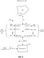
- FIG. 4shows the 2 primary elements in a DAU, the Physical Nodes ( 400 ) and the Local Router ( 401 ).
- the Physical Nodestranslate the RF signals to baseband for the Downlink and from baseband to RF for the Uplink.
- the Local Routerdirects the traffic between the various LAN Ports, PEER Ports and the External Ports.
- the physical nodesconnect to the BTS at radio frequencies (RF).
- RFradio frequencies
- the physical nodescan be used for different operators, different frequency bands, different channels, or the like.
- the physical nodescan combine the downlink and uplink signals via a duplexer or they can keep them separate, as would be the case for a simplex configuration.
- the physical nodes 400are not utilized in the DMU illustrated in FIG. 8 in some embodiments.
- FIG. 4shows an embodiment of the DAU whereby the physical nodes have separate outputs for the uplinks ( 405 ) and separate inputs for the downlink paths ( 404 ).
- the physical nodetranslates the signals from RF to baseband for the downlink path and from baseband to RF for the uplink path.
- the physical nodesare connected to a Local Router via external ports ( 409 , 410 )).
- the routerdirects the uplink data stream from the LAN and PEER ports to the selected External U (uplink) ports. Similarly, the router directs the downlink data stream from the External D (downlink) ports to the selected LAN and PEER ports.
- the LAN and PEER portsare connected via an optical fiber to a network of DMUs and DRUs.
- the network connectioncan also use copper interconnections such as CAT 5 or 6 cabling, or other suitable interconnection equipment.
- the DAUis also connected to the internet network using IP ( 406 ).
- An Ethernet connection ( 408 )is also used to communicate between the Host Unit and the DAU.
- the DRUcan also connect directly to the Remote Operational Control center ( 407 ) via the Ethernet port. Additional description related to DAUs is provided in U.S. Patent Application Publication No. 2013/0114963, incorporated by reference above.
- FIG. 5shows the 2 primary elements in a DRU, the Physical Nodes ( 501 ) and the Remote Router ( 500 ).
- the DRUincludes both a Remote Router and Physical Nodes.
- the Remote Routerdirects the traffic between the LAN ports, External Ports and PEER Ports.
- the physical nodesconnect to the BTS at radio frequencies (RF).
- RFradio frequencies
- the physical nodescan be used for different operators, different frequency bands, different channels, etc.
- FIG. 5shows an embodiment whereby the physical nodes have separate inputs for the uplinks ( 504 ) and separate outputs for the downlink paths ( 503 ).
- the physical nodetranslates the signals from RF to baseband for the uplink path and from baseband to RF for the downlink path.
- the physical nodesare connected to a Remote Router via external ports ( 506 , 507 ).
- the routerdirects the downlink data stream from the LAN and PEER ports to the selected External D ports. Similarly, the router directs the uplink data stream from the External U ports to the selected LAN and PEER ports.
- the DRUalso contains a Ethernet Switch ( 505 ) so that a remote computer or wireless access points can connect to the internet. Additional description related to DRUs is provided in U.S. Patent Application Publication No. 2013/0114963, incorporated by reference above.
- FIG. 6depicts a DAS network that includes multiple DMUs, one or more DAUs, and multiple DRUs in an DMU and DAU network topology.
- the Local Routersillustrated by DMU A and DMU B, and DAU L, are shown in a Daisy Chain configuration. Although a single DAU is illustrated for purposes of clarity, additional DAUs can be utilized in this implementation.
- the Remote Routersillustrated by portions of DRUs 601 , 605 , 606 , 607 , and 609 , are shown in a star and/or daisy chain configuration. By comparison with FIG. 5 , it can be seen that the remote router 601 A and the physical node 601 B are both components of the DRU.
- the local routers in the DMUs and DAUscan be interconnected via a PEER port, illustrated by optical cables 617 and 620 .
- the Local routerscan connect to the remote routers in the DRUs via an optical, copper, or other suitable connection.
- the remote routers in the DRUscan be connected in a daisy chain configuration with other DRUs or they may be connected with a local router via a star configuration.
- the PEER ports in a DMUare used when there is no direct connection between a physical node connected to a local router (e.g., DMU) and a physical node connected to a remote router (e.g., DRU). PEER ports at the DRU are used for daisy chaining between two or more DRUs.
- DMUs 600 / 604receive digital signals from BBU networks 631 / 633 via optical cables 630 / 632 .
- DMU 600is connected to DRU 601 via optical cable 615 and 616 .
- DRU 605is connected to DRU 605 via optical cables 619 A and 619 B.
- DMU 604is connected to DRUs 606 and 607 in a star configuration using optical cables 618 and 621 .
- DAU 608is connected to DRU 609 via optical cable 622 .
- FIG. 7shows an embodiment illustrating an application employing a base station/base band unit hotel where multiple BTSs and BBUs can be interconnected to serve a given geographical area.
- FIGS. 6 and 7provide illustrations of related network topologies in which digital signals are received by DMUs 600 / 604 from BBUs via optical cables and RF signals are received by DAU(s) 608 from BTS(s) via RF cables.
- DMUs 600 / 604from BBUs via optical cables
- RF signalsare received by DAU(s) 608 from BTS(s) via RF cables.
- one or more three-sector BTSs and one or more three-sector BBUscan be connected to a Daisy Chained DAS network.
- the BBUsmay represent independent wireless network operators, multiple bands, and/or multiple interface standards (CPRI, OBSAI, ORI, etc.).
- the BTSsmay represent independent wireless network operators and interface with DAUs at RF.
- DAU 1 ( 702 )receives downlink signals from BTS N Sector 1 ( 709 ) via RF cable 711 .
- DAU 1 ( 702 )transports the desired signals to DRU 2 ( 704 ) via optical cable 703 .
- Optical cable 705transports all the optical signals to DRU 3 ( 706 ).
- the other DRUs in the daisy chainare involved in passing the optical signals onward to DRU 1 ( 707 ).
- DAU 1 ( 702 )is networked with DAU 2 ( 708 ) to allow the downlink signals from BTS N Sector 2 to be transported to all the DRUs in Cell 1 .
- DAU 2 ( 708 )receives downlink signals from BTS Sector N ( 709 ) via DAU 1 as well as from BTS Sector 2 ( 931 ) via RF cable 732 .
- DMU 1( 712 ) interfaces to BBU 1 sector 1 ( 701 ).
- DMU 1is interconnected with DAU 3 743 via optical cable 741 .
- the networking of the DAUs to the DMUsprovides a mechanism to collate signals from BTSs with signals from BBUs. Accordingly, analog RF signals from the BTS(s) and digital optical signals from the BBU(s) can be routed to desired DRUs using the topology illustrated in FIG. 7 .
- analog signals from BTSs and digital signals from BBUscan be received by the DAS network by using DAUs and DMUs, respectively.
- the DAS systemprovided by embodiments of the present invention can be considered as input signal agnostic, since it can receive digital inputs from the BBU networks as well as analog RF inputs from the BTS and then communicate those signals through the system to the remote antennas.
- the systemcan receive inputs at the remote antennas and then communicate those signals in either digital or analog format to the BBUs or DAUs.
- FIG. 8shows a block diagram of a Digital Multiplexer Unit (DMU).
- the DMU 800includes both a Router and BBU interface nodes.
- the Routerdirects the traffic between the LAN ports, BBU Ports and PEER Ports.
- the BBU nodescan be used for different operator BBU equipment.
- the routerdirects the uplink data stream from the LAN and PEER ports to the selected BBU ports.
- the routerdirects the downlink data stream from the BBU ports to the selected LAN and PEER ports.
- the BBU porttranslates the uplink signals destined for its specific port to the interface standard used by the BBU connected to that specific port.
- the downlink signal from a BBU portis translated from the specific BBU protocol standard to a common baseband signal used to collate the various downlink signals.
- the DMUalso contains an Ethernet port ( 802 ) so that a remote computer or wireless access points can connect to the internet.
- the LAN ports of the DMUinterface to the various DRUs connected to the DMU.
- the PEER portsare used to interface to other DMUs or DAUs.
- the DMUdiffers from a DAU in several respects.
- the interface to the base stationis via RF, that is, analog RF signals being received at the DAU.
- the base stationincludes two entities: a base band unit (BBU), which performs digital baseband signal processing, and an RF unit, which can also be referred to as a radio unit.
- BBUbase band unit
- the BBUpasses the digital signal to the RF unit, which upconverts the signal to RF and provides the signal to the DAU, which then converts the RF signal to a digital signal.
- Embodiments of the present inventionuse the DMU to receive the digital signal from the BBU, removing the process of digital to RF conversion followed by RF to digital conversion.
- embodimentsuse the DMU, which provides a digital interface directly to the BBU, thereby bypassing the radio unit in the BTS and bypassing the RF portion present in a DAU.
- signal processingmay be performed on the digital signals received from the BBU, for example, at BBU port 1 , before the digital signals are transmitted to the DRUs through, for example, LAN port 1 .
- the digital signals received at the BBU portsdo not have to be identical to the digital signals transmitted at the LAN ports.
- the use of the term digital signals hereinincludes implementations in which digital signals are received, processed by the DMU, and the digital signals are transmitted, not requiring that the received and transmitted digital signals are identical.
- One of ordinary skill in the artwould recognize many variations, modifications, and alternatives.
- inputs 808are digital inputs from the BBU network and outputs 803 are digital outputs to the DRUs.
- the DMU 800also is able to receive IP traffic from the internet 805 or other source of IP data. Accordingly, both cellular traffic from the BBU network and IP traffic from the internet can move both upstream and downstream through the DMU as illustrated in FIG. 8 .
- FIG. 9is a simplified flowchart illustrating a method of routing signals in a DAS according to an embodiment of the present invention.
- the DASincludes a plurality of Digital Multiplexer Units (DMUs) and a plurality of Digital Remote Units (DRUs).
- the methodincludes receiving, at ports of the plurality of DMUs, digital signals from sector ports of corresponding Base Band Units (BBUs).
- BBUsBase Band Units
- the ports of the DMUare input/output ports that send and receive digital signals, which may be digital optical signals.
- the sector ports of the BBUsare associated with sectors of the BBU and are also input/output ports that send and receive digital signals, which may be digital optical signals.
- the methodalso includes routing the digital signals between the plurality of DMUs.
- the DMUsare coupled to each other, for example, at PEER ports, using optical fiber, enabling communication between the DMUs.
- Routing of the digital signals between the plurality of DMUscan include collating a first digital signal received from a first BBU and a second digital signal received from a second BBU.
- the digital signalswhich can, for example, be associated with Sector 1 of the first BBU and Sector 1 of the second BBU, can then be routed as a combined signal.
- the collated digital signalis directed to one of the plurality of DRUs, where the signals can be processed and broadcast using the remote antennas.
- the methodincludes transporting the digital signals between the plurality of DMUs and a plurality of DRUs.
- the coupling of the DMUs and the DRUsfor example, using optical fiber, enables the digital signals received from the BBUs to be transported to the DRUs and for signals received at the DRUs to be transported to the BBUs.
- routing the digital signals between the DMUscomprises using routing tables. These routing tables can be stored or otherwise provided at a server coupled to the plurality of DMUs. In another implementation, the routing tables are stored or otherwise provided at one or more of the DRUs. In still another implementation, the routing tables, for example, for each DMU and/or each DRU are stored in the cloud.
- the routing tablescan include Merge Blocks that facilitate merging of signals received at multiple DRUs. In an embodiment, a power level of each carrier in each DRU is independently controlled, improving system performance.
- FIG. 9provides a particular method of routing signals in a DAS according to an embodiment of the present invention. Other sequences of steps may also be performed according to alternative embodiments. For example, alternative embodiments of the present invention may perform the steps outlined above in a different order. Moreover, the individual steps illustrated in FIG. 9 may include multiple sub-steps that may be performed in various sequences as appropriate to the individual step. Furthermore, additional steps may be added or removed depending on the particular applications.
- One of ordinary skill in the artwould recognize many variations, modifications, and alternatives.
- router tablesare used to configure the networked DAUs.
- the local router tablesestablish the mapping of the inputs to the various outputs.
- Internal Merge blocksare utilized for the Downlink Tables when the inputs from an External Port and a PEER Port need to merge into the same data stream.
- Merge blocksare used in the Uplink Tables when the inputs from the LAN Ports and PEER Ports need to merge into the same data stream.
- the remote router tablesestablish the mapping of the inputs to the various outputs.
- Internal Merge blocksare utilized for the Downlink Tables when the inputs from a LAN Port and a PEER Port need to merge into the same data stream.
- Merge blocksare used in the Uplink Tables when the inputs from the External Ports and PEER Ports need to merge into the same data stream. Additional description related to router tables is provided in U.S. Patent Application Publication No. 2013/0114963, incorporated by reference above.
- the amount of radio resources(such as RF carriers, the power level of each carrier, LTE Resource Blocks, CDMA codes or TDMA time slots) assigned to a particular DMU/DRU or group of DMUs/DRUs can be set via software control to meet desired capacity and throughput objectives or wireless subscriber needs.
- Applications of the present inventionare suitable to be employed with distributed base stations, distributed baseband units, distributed antenna systems, distributed repeaters, mobile equipment and wireless terminals, portable wireless devices, and other wireless communication systems such as microwave and satellite communications.
- FIG. 10is a schematic block diagram of a Radio Access Network (RAN) 1000 according to an embodiment of the present invention.
- the RAN 1000provides connection between the Core Network 1010 , in this case, such as an Evolved Packet Core (EPC) network, and user equipment including cellular devices, public safety equipment and Wi-Fi equipment.
- the Core Network 1010is connected to a base transceiver station (BTS)/baseband unit (BBU) pool 1020 by Gigabit Ethernet (GbE) backhaul transport, for example, using CAT6/7 cables.
- BTS/BBU pool 1020may include one or more base transceiver stations (BTSs) 1022 and one or more baseband units (BBUs) 1024 .
- BTSsbase transceiver stations
- BBUsbaseband units
- the BTS(s) 1022 and BBU(s) 1024are in bidirectional communication with one or more universal base station interface trays (UBiTs) 1030 , which aggregate and transport base station resources to remote units (e.g., DRUs 1040 , 1042 , 1044 , etc.).
- the UbiT 1030is multi-operator, multi-band/channel and multi-standard, and provides an RF and fronthaul interface for packetized data (e.g., CPRI data, ORI data, etc.).
- the fronthaul interface of the UbiT 1030may be included on a single chip.
- the fronthaul interfacemay be included on one board or multiple boards as a rack mounted unit.
- the UbiT 1030implements an open application programming interface (API) as its data interface.
- APIapplication programming interface
- the UbiT 1030provides up to and above 10 Gbps per wavelength digital transport.
- the UbiT 1030includes one or more RF conditioners (RFCs), a host unit, and a baseband interface (BBI).
- the BBIcan be a digital multiplexer as described herein.
- the digital remote unitscan be in communication with indoor or outdoor antennas, WiFi access points (APs), and/or IP/IoT device(s) or application(s), providing support for cellular service, the public safety band and WiFi.
- WiFi access pointsAPs
- IP/IoT device(s) or application(s)providing support for cellular service, the public safety band and WiFi.
- the WiFi APs and/or IP/IoT device(s)can receive IP traffic from the DRUs.
- IP trafficcan be routed between the DMUs and the DRUs along with the I/Q data.
- the DRUscan be software configurable, and be mid power (e.g., +30 dBm/ch, +37 dBm/ch, etc.), or high power (e.g., +43 dBm/ch, +46 dBm/ch, etc.). They can provide channelized processing, capacity routing on demand and IP backhaul (e.g., 1 Gbps, 10 Gbps, etc.).
- the DRUscan be, for example, any type of remote unit, such as those described herein.
- the BTS/BBU pool 1020 , the UbiT, and the DRUs 1040 , 1042 , 1044may be part of an access network 1015 that may be located at one or more locations remote from core network 1010 .
- FIG. 11is a schematic block diagram of a Centralized Radio Access Network (C-RAN) 1100 according to an embodiment of the present invention.
- the C-RAN 1100provides connection between the Core Network 1110 , such as an EPC network, and user equipment including cellular devices, public safety equipment and WiFi equipment.
- the Core Network 1110is connected to a BBU pool 1120 by GbE backhaul transport, for example, using CAT 6/7 cables.
- the BBU pool 1120may include one or more baseband units (BBUs) 1122 , 1124 .
- BBUsbaseband units
- the BBU pool 1120is in communication with one or more fronthaul interfaces 1130 .
- the fronthaul interfaces 1130may include any packetized approaches and/or transport protocols for switching (e.g., routing input ports to output ports) and/or routing (e.g., using a source and destination address scheme).
- Exemplary fronthaul interfaces 1130may include switches and/or routers for use with CPRI, ORI, Ethernet, CPRI over Ethernet, and the like.
- the fronthaul interfaces 1130may each be included on a single chip.
- the fronthaul interfaces 1130may be included on one board or multiple boards as a rack mounted unit.
- the fronthaul interfaces 1130use DMUs 1132 , 1134 to implement packet-based switching and route packets (e.g., payload I/Q data, Control & Management data, header information, IP traffic, etc.).
- the fronthaul interfaces 1130communicate directly with various locations, as well as with a further DMU 1142 at another location using the interface standard at 10, 40 or 100 Gbps, for example.
- the BBU pool 1120 and the fronthaul interface 1130may together form a central office 1115 .
- the central office 1115may be located remotely from the core network 1110 in some embodiments.
- the DMUs 1132 , 1134 , 1142implement open APIs based on a packetized protocol in one embodiment and provide, for example, an up to and above 10 Gbps per wavelength interface.
- the DMUs 1132 , 1134 , 1142provide integrated wavelength division multiplexing (WDM) for, for example, 40 Gbps and 100 Gbps.
- WDMwavelength division multiplexing
- the DMU 1142interfaces with one or more DRUs (e.g., DRUs 1152 , 1154 , 1156 , 1162 , 1164 , 1166 ).
- the DMU 1142 and the DRUs 1152 , 1154 , 1156 , 1162 , 1164 , 1166may be part of an access network 1140 located at one or more locations remote from the core network 1110 and or the central office 1115 .
- the fronthaul interfaces 1130can include any of the DMUs described herein.
- the DMUs 1132 , 1134 , 1142have a forwarding plane and a control plane.
- the forwarding planeincludes the routing paths through the DMU which are configured by the C&M (Control and Management).
- the C&M configurationis located in the cloud as described further herein, although these functions can alternatively be configured in a server, as described further herein.
- the C&Mestablishes the routing paths between the inputs and outputs of each DMU.
- the DMUs 1132 , 1134may be configured to receive a plurality of signals from one or more BBUs 1122 , 1124 .
- the DMUs 1132 , 1134may extract a subset of the plurality of signals intended for a particular DRU 1152 , 1154 , 1156 , 1162 , 1164 , 1166 , as specified by C&M information, as described further herein.
- the DMUs 1132 , 1134may aggregate the subset of the plurality of signals into a stream, and route the stream to one or more DRUs 1152 , 1154 , 1156 , 1162 , 1164 , 1166 .
- the streamcan be routed to the one or more DRUs 1152 , 1154 , 1156 , 1162 , 1164 , 1166 via the DMU 1142 .
- the DMU 1142may decompose the stream, e.g., back into the subset of signals, before routing it to the one or more DRUs 1152 , 1154 , 1156 , 1162 , 1164 , 1166 .
- the DMU 1142may be collocated with the DRUs 1152 , 1154 , 1156 , 1162 , 1164 , 1166 , for example, at a location remote from the DMUs 1132 , 1134 .
- the DMU 1142can be eliminated.
- the DMUs 1132 , 1134may route the stream directly to the one or more DRUs 1152 , 1154 , 1156 , 1162 , 1164 , 1166 .
- the fronthaul interfaces 1130can communicate directly with a DRU. This DRU can be daisy chained or deployed in a star configuration with one or more additional DRUs.
- the DRUs 1152 , 1154 , 1156 , 1162 , 1164 , 1166can be in communication with IP/IoT device(s) or application(s), and can provide support for cellular service, the public safety band and WiFi.
- the WiFi APs and/or IP/IoT device(s)can receive IP traffic from the RUs. Accordingly, WiFi APs, in addition to other IoT devices can receive IP traffic.
- the DRUs 1152 , 1154 , 1156 , 1162 , 1164 , 1166can be software configurable, and be low power (e.g., +18 dBm/ch, +23 dBm/ch, etc.), mid power (e.g., +30 dBm/ch, +37 dBm/ch, etc.), or high power (e.g., +43 dBm/ch, +46 dBm/ch, etc.). They can provide channelized processing, capacity routing on demand and IP backhaul (e.g., 1 Gbps, 10 Gbps, higher bandwidths, etc.).
- the low power DRUsare wideband or narrowband (e.g., cover a frequency range from 150 MHz to 70 GHz), have an instantaneous bandwidth, for example, of up to and above 100 MHz, have agile channel positioning, are single, quad- or octo-band/channel, have integrated antennas and WiFi APs and provide IP backhaul.
- the mid power (e.g., hd30-4) and high power (e.g., hd43-4) DRUsare narrowband, quad band RUs that can be in communication with indoor or outdoor antennas and WiFi APs, and can have an instantaneous bandwidth, for example, up to and above 100 MHz.
- the DRUs 1152 , 1154 , 1156 , 1162 , 1164 , 1166can be, for example, any type of remote unit, such as those described herein.
- FIG. 12is a schematic block diagram illustrating a multi-operator C-RAN 1200 according to an embodiment of the present invention.
- the C-RAN 1200provides connection between the Core Networks 1202 , 1204 , 1206 , such as EPC networks, and user equipment including cellular devices, public safety equipment and WiFi equipment.
- the Core Network 1202is connected to a Central Office Operator 1210 that operates a BBU pool 1212 and a front haul interface 1215 .
- the Core Network 1202may be connected to the BBU pool 1212 of the Central Office Operator 1210 by GbE backhaul transport, for example, using CAT 6/7 cables.
- the BBU pool 1212may include one or more baseband units (BBUs) 1213 , 1214 .
- BBUsbaseband units
- the Core Network 1204is connected to another Central Office Operator 1220 that operates a BBU pool 1222 and a fronthaul interface 1225 .
- the Core Network 1202may be connected to the BBU pool 1222 of the Central Office Operator 1220 by GbE backhaul transport, for example, using CAT 6/7 cables.
- the BBU pool 1222may include one or more baseband units (BBUs) 1223 , 1224 .
- the Core Network 1206is connected to another Central Office Operator 1230 that operates a BBU pool 1232 and a fronthaul interface 1235 .
- the Core Network 1202may be connected to the BBU pool 1232 of the Central Office Operator 1230 by GbE backhaul transport, for example, using CAT 6/7 cables.
- the BBU pool 1232may include one or more baseband units (BBUs) 1233 , 1234 .
- each Central Office Operator 1210 , 1220 , 1230has a respective BBU pool and fronthaul interface, as well as a backhaul to a Core Network 1202 , 1204 , 1206 , respectively.
- a Core Network 1202 , 1204 , 1206the Core Network 1202 , 1204 , 1206
- the Central Office Operators 1210 , 1220 , 1230may be located remotely from the Core Networks 1202 , 1204 , 1206 , respectively, in some embodiments.
- Each of the BBU pools 1212 , 1222 , 1232is in communication with one or more fronthaul interfaces 1215 , 1225 , 1235 , respectively.
- the fronthaul interfaces 1215 , 1225 , 1235may include any packetized approaches and/or transport protocols for switching (e.g., routing input ports to output ports) and/or routing (e.g., using a source and destination address scheme).
- Exemplary fronthaul interfaces 1215 , 1225 , 1235may include switches and/or routers for use with CPRI, ORI, Ethernet, CPRI over Ethernet, and the like.
- the fronthaul interfaces 1215 , 1225 , 1235may each be included on a single chip.
- the fronthaul interfaces 1215 , 1225 , 1235may be included on one board or multiple boards as a rack mounted unit.
- the fronthaul interfaces 1215 , 1225 , 1235use DMUs (e.g., DMUs 1216 , 1217 , 1226 , 1227 , 1236 , 1237 ) to implement packet-based switching and route CPRI packets (payload I/Q data, Control & Management data, header information, IP traffic, etc.).
- the fronthaul interfaces 1215 , 1225 , 1235communicate directly with various locations, as well as with a further DMU 1242 at another location using the interface standard at 10, 40 or 100 Gbps, for example.
- the DMUs 1216 , 1217 , 1226 , 1227 , 1236 , 1237 , 1242implement open APIs based on a packetized protocol in one embodiment and provide, for example, an up to and above 10 Gbps per wavelength interface.
- the DMUs 1216 , 1217 , 1226 , 1227 , 1236 , 1237 , 1242provide integrated wavelength division multiplexing (WDM) for, for example, 40 Gbps and 100 Gbps.
- WDMwavelength division multiplexing
- the DMU 1242interfaces with one or more DRUs (e.g., DRUs 1252 , 1254 , 1256 , 1262 , 1264 , 1266 ).
- the DMU 1242 and the DRUs 1252 , 1254 , 1256 , 1262 , 1264 , 1266may be part of an access network 1240 located at one or more locations remote from the Core Networks 1202 , 1204 , 1206 and/or the Central Office Operators 1210 , 1220 , 1230 .
- the DMU 1242is capable of aggregating content from multiple different Central Office Operators 1210 , 1220 , 1230 and sending the aggregated content to one or more DRUs 1252 , 1254 , 1256 , 1262 , 1264 , 1266 , which are operator agnostic.
- FIG. 11relates to a single operator C-RAN
- the embodiment shown and described with respect to FIG. 12relates to a multi-operator C-RAN.
- the fronthaul interfaces 1215 , 1225 , 1235can include any of the DMUs described herein.
- the DMUs 1216 , 1217 , 1226 , 1227 , 1236 , 1237 , 1242have a forwarding plane and a control plane.
- the forwarding planeincludes the routing paths through the DMU which are configured by the C&M (Control and Management).
- the C&M configurationis located in the cloud as described further herein, although these functions can alternatively be configured in a server, as described further herein.
- the C&Mestablishes the routing paths between the inputs and outputs of each DMU.
- the DMUs 1216 , 1217 , 1226 , 1227 , 1236 , 1237may be configured to receive a plurality of signals from one or more BBUs 1213 , 1214 , 1223 , 1224 , 1233 , 1234 .
- the DMUs 1216 , 1217 , 1226 , 1227 , 1236 , 1237may extract a subset of the plurality of signals intended for a particular DRU 1252 , 1254 , 1256 , 1262 , 1264 , 1266 , as specified by C&M information, as described further herein.
- the DMUs 1216 , 1217 , 1226 , 1227 , 1236 , 1237may aggregate the subset of the plurality of signals into a stream, and route the stream to one or more DRUs 1252 , 1254 , 1256 , 1262 , 1264 , 1266 .
- the streamcan be routed to the one or more DRUs 1252 , 1254 , 1256 , 1262 , 1264 , 1266 via the DMU 1242 .
- the DMU 1242may decompose the stream, e.g., back into the subset of signals, before routing it to the one or more DRUs 1252 , 1254 , 1256 , 1262 , 1264 , 1266 .
- the DMU 1242may be collocated with the DRUs 1252 , 1254 , 1256 , 1262 , 1264 , 1266 via the DMU 1242 , for example, at a location remote from the DMUs 1216 , 1217 , 1226 , 1227 , 1236 , 1237 .
- the DMU 1242can be eliminated.
- the DMUs 1216 , 1217 , 1226 , 1227 , 1236 , 1237may route the stream directly to the one or more DRUs 1252 , 1254 , 1256 , 1262 , 1264 , 1266 .
- the fronthaul interfaces 1215 , 1225 , 1235can communicate directly with a DRU. This DRU can be daisy chained or deployed in a star configuration with one or more additional DRUs.
- the DRUs 1252 , 1254 , 1256 , 1262 , 1264 , 1266can be in communication with IP/IoT device(s) or application(s), and can provide support for cellular service, the public safety band and WiFi.
- the WiFi APs and/or IP/IoT device(s)can receive IP traffic from the RUs. Accordingly, WiFi APs, in addition to other IoT devices can receive IP traffic.
- the DRUs 1252 , 1254 , 1256 , 1262 , 1264 , 1266can be software configurable, and be low power (e.g., +18 dBm/ch, +23 dBm/ch, etc.), mid power (e.g., +30 dBm/ch, +37 dBm/ch, etc.), or high power (e.g., +43 dBm/ch, +46 dBm/ch, etc.). They can provide channelized processing, capacity routing on demand and IP backhaul (e.g., 1 Gbps, 10 Gbps, higher bandwidths, etc.).
- the low power DRUsare wideband or narrowband (e.g., cover a frequency range of 150 MHz to 70 GHz), have an instantaneous bandwidth, for example, of up to and above 100 MHz, have agile channel positioning, are single, quad- or octo-band/channel, have integrated antennas and WiFi APs and provide IP backhaul.
- the mid power (e.g., hd30-4) and high power (e.g., hd43-4) DRUsare narrowband, quad band RUs that can be in communication with indoor or outdoor antennas and WiFi APs, and can have an instantaneous bandwidth, for example, up to and above 100 MHz.
- the DRUs 1252 , 1254 , 1256 , 1262 , 1264 , 1266can be, for example, any type of remote unit, such as those described herein.
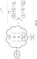
- FIG. 13is a schematic block diagram of a Cloud Radio Access Network 1300 according to an embodiment of the present invention.
- the Cloud RAN 1300provides connection between the Core Network 1310 , such as an EPC network, and user equipment including cellular devices, public safety equipment and WiFi equipment.
- the Core Network 1310is connected to a Data Center 1315 by GbE backhaul transport, for example, using CAT 6/7 cables.
- the Data Center 1315may include one or more virtual BBUs (vBBUs) 1320 and one or more fronthaul interfaces 1340 .
- the virtual BBUs 1320are implemented using off-the-shelf data servers.
- the fronthaul interfaces 1340can include any of the DMUs or DRUs described herein.
- the DMUs 1352 (and internal to fronthaul interfaces 1340 ) and DRUs 1362 , 1364 , 1366 , 1372 , 1374 , 1376have a forwarding plane and a control plane.
- the forwarding planedefines the routing paths through the DMUs and DRUs, which are configured by the C&M.
- the C&M configurationis located in the cloud in one embodiment, although these functions can alternatively be configured in a remote server 1345 .
- the C&Mestablishes the routing paths between the inputs and outputs of each DMU and DRU.
- the Data Center 1315is implemented via a Software Defined Network (SDN) 1330 and provides remote control and management functionality.
- SDNSoftware Defined Network
- control of the fronthaul interfaces 1340can be handled in the cloud.
- the fronthaul interfaces 1340implement packet-based switching and route (forwarding plane) packets between DMUs and DRUs.
- the fronthaul interfaces 1340may each be included on a single chip.
- the fronthaul interfaces 1340may be included on one board or multiple boards as a rack mounted unit.
- the fronthaul interfaces 1340may include one or more DMUs as described further herein with respect to FIGS. 11 and 12 , and may be configured to receive a plurality of signals from one or more virtual BBUs 1320 .
- the DMUs of the fronthaul interfaces 1340may extract a subset of the plurality of signals intended for a particular DRU 1362 , 1364 , 1366 , 1372 , 1374 , 1376 , as specified by C&M information, as described further herein.
- the DMUs of the fronthaul interfaces 1340may aggregate the subset of the plurality of signals into a stream, and route the stream to one or more DRUs 1362 , 1364 , 1366 , 1372 , 1374 , 1376 .
- the streamcan be routed to the one or more DRUs 1362 , 1364 , 1366 , 1372 , 1374 , 1376 via the DMU 1352 .
- the DMU 1352may decompose the stream, e.g., back into the subset of signals, before routing it to the one or more DRUs 1362 , 1364 , 1366 , 1372 , 1374 , 1376 .
- the DMU 1352may be collocated with the DRUs 1362 , 1364 , 1366 , 1372 , 1374 , 1376 via the DMU 1352 , for example, at a location remote from the fronthaul interfaces 1340 .
- the DMU 1352can be eliminated.
- the DMUs of the fronthaul interfaces 1340may route the stream directly to the one or more DRUs 1362 , 1364 , 1366 , 1372 , 1374 , 1376 .
- the fronthaul interfaces 1340can communicate directly with a DRU. This DRU can be daisy chained or deployed in a star configuration with one or more additional DRUs.
- the Data Center 1315communicates directly with various locations, as well as with a DMU 1352 at one location using the interface standard at 10, 40 or 100 Gbps, for example.
- the DMU 1352implements an open API based on a packetized protocol and provides, for example, an up to and above 10 Gbps per wavelength interface.
- the DMU 1352provides integrated wavelength division multiplexing (WDM) for, for example, 40 Gbps and 100 Gbps.
- WDMwavelength division multiplexing
- the DMU 1352interfaces with one or more DRUs (e.g., DRUs 1362 , 1364 , 1366 , 1372 , 1374 , 1376 ).
- the DMU 1352 and the DRUs 1362 , 1364 , 1366 , 1372 , 1374 , 1376may be part of an access network 1350 that may be located remotely at one or more locations.
- the DRUs 1362 , 1364 , 1366 , 1372 , 1374 , 1376can be in communication with IP/IoT device(s) or application(s), and can provide support for cellular service, the public safety band and WiFi.
- the WiFi APs and/or IP/IoT device(s)can receive IP traffic from the RUs.
- the DRUs 1362 , 1364 , 1366 , 1372 , 1374 , 137can be software configurable, and be low power (e.g., +18 dBm/ch, +23 dBm/ch, etc.), mid power (e.g., +30 dBm/ch, +37 dBm/ch, etc.), or high power (e.g., +43 dBm/ch, +46 dBm/ch, etc.). They can provide channelized processing, capacity routing on demand and IP backhaul (e.g., 1 Gbps, 10 Gbps, etc.).
- the low power DRUsare wideband or narrowband (e.g., cover a frequency range from 150 MHz to 70 GHz), have an instantaneous bandwidth, for example, of up to and above 100 MHz, have agile channel positioning, are single or quad band/channel, have integrated antennas and WiFi APs and provide IP backhaul.
- the mid power (e.g., hd30-4) and high power (e.g., hd43-4) DRUsare narrowband, quad band DRUs that can be in communication with indoor or outdoor antennas and WiFi APs, and can have an instantaneous bandwidth, for example, up to and above 100 MHz.
- the DRUs 1362 , 1364 , 1366 , 1372 , 1374 , 1376can be, for example, any type of remote unit, such as those described herein.
- the embodiment shown in FIG. 13has a substantially reduced amount of equipment utilized for deployment.
- the implementation shown in FIG. 13does not necessarily require UBiTs and RFCs.
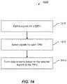
- FIG. 14is a simplified flowchart 1400 illustrating a method of control and management (C&M) of the RAN according to an embodiment of the present invention.
- C&Mcontrol and management
- some or all of the C&M functionality illustrated by flowchart 1400may be implemented in a cloud network, as described further herein.
- signalsare defined at a DMU. Although described as occurring “at a DMU”, it is contemplated that the signals can be defined on a cloud (e.g., by an application over the Internet), by a remote server, and/or by plugging directly into the DMU.
- FIG. 15is a screen shot of an exemplary user interface 1500 for defining signals in one implementation of step 1410 of FIG. 14 .
- a DMUis selected (“O1_HostQS-Cw01”).
- the DMU selected in FIG. 15is a quad-band unit defined by bands of 700 MHz, 850 MHz, 1900 MHz and AWS. Signals may be defined by their center frequency, bandwidth, start frequency-stop frequency, a table, a graphic, and/or the like.
- a tableis selected that is pre-populated with bands defined by regulatory bodies (e.g., “700-A 698-704/728-734 MHz”).
- the signalsmay also be defined by assigning names (e.g., “ATT-700-B-S1”).
- a checkis made to ensure that the number of defined signals is less than or equal to a maximum number of signals that that DMU can process. If the number of defined signals exceeds the maximum number of signals, the user requesting definition of the signals may be informed.
- the signalscan be allocated to specific DRUs.
- signalsare selected for each DRU. It is contemplated that the signals can be allocated on a cloud (e.g., by an application over the Internet), by a remote server, and/or by plugging directly into one or more DRUs.
- FIG. 16is a screen shot of an exemplary user interface 1600 for selecting signals in one implementation of step 1412 of FIG. 14 .
- a DRUis selected (“hd30-11”).
- the DRU selected in FIG. 16is a quad-band unit defined by bands of 700 MHz, 850 MHz, 1900 MHz and AWS.
- Drop-down boxesallow a user to select signals according to their name assigned in step 1410 (e.g., “ATT-700-A-S1”), from the pool of all signals defined in step 1410 . By selecting a particular signal name, the signal corresponding to that signal name will be processed on that particular DRU.
- a checkmay be made to ensure that the number of selected signals is less than or equal to a maximum number of signals that that DRU can process. If the number of selected signals exceeds the maximum number of signals, the user requesting selection of the signals may be informed. In some embodiments, at step 1412 of FIG. 14 , a check may be made to ensure that the total bandwidth of the selected signals for the cluster of DRUs fed from the DMU of step 1410 is less than or equal to the maximum bandwidth of signals that can be transported over the optical link between the DMU and the DRUs. If the total bandwidth exceeds the maximum bandwidth, the user requesting selection of the signals may be informed.
- serial data streamscan be created.
- data streamsare formed for each DRU or cluster of DRUs based on the selected signals at the DMU.
- the signalscan be defined on a cloud (e.g., by an application over the Internet), by a remote server, and/or by plugging directly into the DMU.
- the selected signalsmay be routed from the DMU to the one or more DRUs specified at step 1412 .
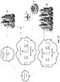
- FIG. 17is an overall schematic block diagram of a Cloud RAN according to an embodiment of the invention.
- a Core Network 1710communicates via GbE backhaul transport with a Data Center 1715 (comprising virtual BBUs 1717 ), a Local Data Center 1720 (comprising virtual BBUs 1722 , fronthaul interfaces 1726 , and an SDN 1724 ), and a Mega Data Center 1730 (comprising virtual BBUs 1732 , fronthaul interfaces 1736 , and an SDN 1734 ).
- the Data Center 1715 , Local Data Center 1720 and Mega Data Center 1730use packetized fronthaul transport to provide outdoor and indoor DAS coverage at a variety of locations 1740 , 1752 , 1754 , 1756 , 1760 .
- the Cloud RAN shown in FIG. 17can be implemented using the components illustrated with respect to FIG. 13 , for example.
Landscapes
- Engineering & Computer Science (AREA)
- Computer Networks & Wireless Communication (AREA)
- Signal Processing (AREA)
- Power Engineering (AREA)
- Physics & Mathematics (AREA)
- Electromagnetism (AREA)
- Mobile Radio Communication Systems (AREA)
Abstract
Description
| APPENDIX I |
| Glossary of Terms |
| ACLR | Adjacent Channel Leakage Ratio | ||
| ACPR | Adjacent Channel Power Ratio | ||
| ADC | Analog to Digital Converter | ||
| AQDM | Analog Quadrature Demodulator | ||
| AQM | Analog Quadrature Modulator | ||
| AQDMC | Analog Quadrature Demodulator Corrector | ||
| AQMC | Analog Quadrature Modulator Corrector | ||
| BPF | Bandpass Filter | ||
| CDMA | Code Division Multiple Access | ||
| CFR | Crest Factor Reduction | ||
| DAC | Digital to Analog Converter | ||
| DET | Detector | ||
| DHMPA | Digital Hybrid Mode Power Amplifier | ||
| DDC | Digital Down Converter | ||
| DNC | Down Converter | ||
| DPA | Doherty Power Amplifier | ||
| DQDM | Digital Quadrature Demodulator | ||
| DQM | Digital Quadrature Modulator | ||
| DSP | Digital Signal Processing | ||
| DUC | Digital Up Converter | ||
| EER | Envelope Elimination and Restoration | ||
| EF | Envelope Following | ||
| ET | Envelope Tracking | ||
| EVM | Error Vector Magnitude | ||
| FFLPA | Feedforward Linear Power Amplifier | ||
| FIR | Finite Impulse Response | ||
| FPGA | Field-Programmable Gate Array | ||
| GSM | Global System for Mobile communications | ||
| I-Q | In-phase/Quadrature | ||
| IF | Intermediate Frequency | ||
| LINC | Linear Amplification using Nonlinear Components | ||
| LO | Local Oscillator | ||
| LPF | Low Pass Filter | ||
| MCPA | Multi-Carrier Power Amplifier | ||
| MDS | Multi-Directional Search | ||
| OFDM | Orthogonal Frequency Division Multiplexing | ||
| PA | Power Amplifier | ||
| PAPR | Peak-to-Average Power Ratio | ||
| PD | Digital Baseband Predistortion | ||
| PLL | Phase Locked Loop | ||
| QAM | Quadrature Amplitude Modulation | ||
| QPSK | Quadrature Phase Shift Keying | ||
| RF | Radio Frequency | ||
| RRH | Remote Radio Head | ||
| RRU | Remote Radio Head Unit | ||
| SAW | Surface Acoustic Wave Filter | ||
| UMTS | Universal Mobile Telecommunications System | ||
| UPC | Up Converter | ||
| WCDMA | Wideband Code Division Multiple Access | ||
| WLAN | Wireless Local Area Network | ||
Claims (21)
Priority Applications (2)
| Application Number | Priority Date | Filing Date | Title |
|---|---|---|---|
| US16/734,833US11563492B2 (en) | 2013-12-23 | 2020-01-06 | Virtual radio access network using software-defined network of remotes and digital multiplexing switches |
| US18/159,007US12267108B2 (en) | 2013-12-23 | 2023-01-24 | Virtual radio access network using software-defined network of remotes and digital multiplexing switches |
Applications Claiming Priority (5)
| Application Number | Priority Date | Filing Date | Title |
|---|---|---|---|
| US201361920397P | 2013-12-23 | 2013-12-23 | |
| US14/580,585US10637537B2 (en) | 2013-12-23 | 2014-12-23 | Digital multiplexer in a distributed antenna system |
| US201562258289P | 2015-11-20 | 2015-11-20 | |
| US15/358,060US20170250927A1 (en) | 2013-12-23 | 2016-11-21 | Virtual radio access network using software-defined network of remotes and digital multiplexing switches |
| US16/734,833US11563492B2 (en) | 2013-12-23 | 2020-01-06 | Virtual radio access network using software-defined network of remotes and digital multiplexing switches |
Related Parent Applications (1)
| Application Number | Title | Priority Date | Filing Date |
|---|---|---|---|
| US15/358,060ContinuationUS20170250927A1 (en) | 2013-12-23 | 2016-11-21 | Virtual radio access network using software-defined network of remotes and digital multiplexing switches |
Related Child Applications (1)
| Application Number | Title | Priority Date | Filing Date |
|---|---|---|---|
| US18/159,007ContinuationUS12267108B2 (en) | 2013-12-23 | 2023-01-24 | Virtual radio access network using software-defined network of remotes and digital multiplexing switches |
Publications (2)
| Publication Number | Publication Date |
|---|---|
| US20200186250A1 US20200186250A1 (en) | 2020-06-11 |
| US11563492B2true US11563492B2 (en) | 2023-01-24 |
Family
ID=59680260
Family Applications (3)
| Application Number | Title | Priority Date | Filing Date |
|---|---|---|---|
| US15/358,060AbandonedUS20170250927A1 (en) | 2013-12-23 | 2016-11-21 | Virtual radio access network using software-defined network of remotes and digital multiplexing switches |
| US16/734,833ActiveUS11563492B2 (en) | 2013-12-23 | 2020-01-06 | Virtual radio access network using software-defined network of remotes and digital multiplexing switches |
| US18/159,007ActiveUS12267108B2 (en) | 2013-12-23 | 2023-01-24 | Virtual radio access network using software-defined network of remotes and digital multiplexing switches |
Family Applications Before (1)
| Application Number | Title | Priority Date | Filing Date |
|---|---|---|---|
| US15/358,060AbandonedUS20170250927A1 (en) | 2013-12-23 | 2016-11-21 | Virtual radio access network using software-defined network of remotes and digital multiplexing switches |
Family Applications After (1)
| Application Number | Title | Priority Date | Filing Date |
|---|---|---|---|
| US18/159,007ActiveUS12267108B2 (en) | 2013-12-23 | 2023-01-24 | Virtual radio access network using software-defined network of remotes and digital multiplexing switches |
Country Status (1)
| Country | Link |
|---|---|
| US (3) | US20170250927A1 (en) |
Cited By (2)
| Publication number | Priority date | Publication date | Assignee | Title |
|---|---|---|---|---|
| US20210399854A1 (en)* | 2018-09-18 | 2021-12-23 | Telefonaktiebolaget Lm Ericsson (Publ) | Fronthaul configuration based on facilitating cell allocation to baseband units and hubs of a communications network |
| US12267108B2 (en)* | 2013-12-23 | 2025-04-01 | Dali Wireless, Inc. | Virtual radio access network using software-defined network of remotes and digital multiplexing switches |
Families Citing this family (19)
| Publication number | Priority date | Publication date | Assignee | Title |
|---|---|---|---|---|
| US11564110B2 (en) | 2011-11-07 | 2023-01-24 | Dali Wireless, Inc. | Soft hand-off and routing data in a virtualized distributed antenna system |
| SG11201605115VA (en)* | 2013-12-23 | 2016-07-28 | Dali Systems Co Ltd | Digital multiplexer in a distributed antenna system |
| EP3269118B8 (en)* | 2015-03-11 | 2021-03-17 | CommScope, Inc. of North Carolina | Distributed radio access network with adaptive fronthaul |
| WO2017070635A1 (en) | 2015-10-22 | 2017-04-27 | Phluido, Inc. | Virtualization and orchestration of a radio access network |
| WO2018017468A1 (en) | 2016-07-18 | 2018-01-25 | Phluido, Inc. | Synchronization of radio units in radio access networks |
| US12016084B2 (en) | 2018-01-04 | 2024-06-18 | Commscope Technologies Llc | Management of a split physical layer in a radio area network |
| WO2019217391A1 (en)* | 2018-05-07 | 2019-11-14 | Mavenir Networks, Inc. | Method and apparatus for fronthaul compression in cloud ran |
| US11490280B2 (en)* | 2018-09-28 | 2022-11-01 | Telefonaktiebolaget Lm Ericsson (Publ) | Carrier harmonization for RF performance optimization |
| CN112913278B (en) | 2018-10-25 | 2023-08-01 | 康普技术有限责任公司 | Multi-carrier radio point for a centralized radio access network |
| CA3118089A1 (en)* | 2018-10-31 | 2020-05-07 | John Mezzalingua Associates, LLC | Orchestrator and interconnection fabric mapper for a virtual wireless base station |
| JP2023532651A (en) | 2020-06-30 | 2023-07-31 | コムスコープ テクノロジーズ リミティド ライアビリティ カンパニー | An open radio access network with unified remote units that support multiple functional divisions, multiple wireless interface protocols, multiple generations of radio access technologies, and multiple radio frequency bands. |
| CN112865873B (en)* | 2021-02-02 | 2022-03-11 | 四川赛狄信息技术股份公司 | Intermediate frequency signal processor and intermediate frequency signal processing system |
| WO2022188032A1 (en)* | 2021-03-09 | 2022-09-15 | 华为技术有限公司 | Optical communication system and method, optical module, and apparatus applied to optical module |
| CN115189708B (en)* | 2021-04-06 | 2023-07-21 | 大唐移动通信设备有限公司 | AAU and BBU interface rate configuration method, AAU and BBU |
| CN113316212B (en)* | 2021-05-26 | 2022-08-26 | 中国联合网络通信集团有限公司 | Transmission method and device for base station forward data stream |
| CN117176508A (en)* | 2022-05-27 | 2023-12-05 | 中兴通讯股份有限公司 | Access network, fault processing method and system thereof, storage medium and electronic device |
| US20230421205A1 (en)* | 2022-06-22 | 2023-12-28 | Commscope Technologies Llc | Digital donor card for a distributed antenna unit supporting multiple virtual radio points |
| WO2024006760A1 (en)* | 2022-06-28 | 2024-01-04 | Commscope Technologies Llc | Platform agnostic virtualized distributed antenna system deployment |
| WO2024129818A1 (en)* | 2022-12-15 | 2024-06-20 | Commscope Technologies Llc | Method and apparatus for efficient distribution in digital das systems |
Citations (197)
| Publication number | Priority date | Publication date | Assignee | Title |
|---|---|---|---|---|
| US3854122A (en) | 1972-12-12 | 1974-12-10 | Robertshaw Controls Co | Remote station addressing system |
| US4268829A (en)* | 1980-03-24 | 1981-05-19 | The United States Of America As Represented By The Secretary Of The Army | Steerable null antenna processor with gain control |
| US4280128A (en)* | 1980-03-24 | 1981-07-21 | The United States Of America As Represented By The Secretary Of The Army | Adaptive steerable null antenna processor |
| US4887235A (en)* | 1982-12-17 | 1989-12-12 | Symbolics, Inc. | Symbolic language data processing system |
| WO1995001012A1 (en)* | 1993-06-17 | 1995-01-05 | Skydata Corporation | Frame relay protocol-based multiplex switching scheme for satellite mesh network |
| US5805983A (en) | 1996-07-18 | 1998-09-08 | Ericsson Inc. | System and method for equalizing the delay time for transmission paths in a distributed antenna network |
| US5848060A (en)* | 1994-01-11 | 1998-12-08 | Ericsson Inc. | Cellular/satellite communications system with improved frequency re-use |
| US5867763A (en) | 1996-02-08 | 1999-02-02 | Qualcomm Incorporated | Method and apparatus for integration of a wireless communication system with a cable T.V. system |
| CA2306064A1 (en) | 1999-04-22 | 2000-10-22 | Transcept, Inc. | Remote hub arrangement for deploying cell sites especially along a corridor |
| US6167286A (en) | 1997-06-05 | 2000-12-26 | Nortel Networks Corporation | Multi-beam antenna system for cellular radio base stations |
| US20010019952A1 (en)* | 2000-02-14 | 2001-09-06 | Akira Ishida | Wireless base station and a wireless phone |
| US6308085B1 (en) | 1998-03-13 | 2001-10-23 | Kabushiki Kaisha Toshiba | Distributed antenna system and method of controlling the same |
| US20010037395A1 (en) | 2000-03-29 | 2001-11-01 | Transcept Opencell, Inc. | Operations and maintenace architecture for multiprotocol distributed system |
| US20020093926A1 (en) | 2000-12-05 | 2002-07-18 | Kilfoyle Daniel B. | Method and system for a remote downlink transmitter for increasing the capacity of a multiple access interference limited spread-spectrum wireless network |
| US20020187809A1 (en) | 2001-06-08 | 2002-12-12 | Sanjay Mani | Method and apparatus for multiplexing in a wireless communication infrastructure |
| US20030087618A1 (en)* | 2001-11-08 | 2003-05-08 | Junsong Li | Digital FM stereo decoder and method of operation |
| US20030103477A1 (en)* | 2000-04-03 | 2003-06-05 | Yoshiharu Doi | Radio base station,method for controlling the same and program recorded medium |
| US20030139152A1 (en)* | 2000-04-03 | 2003-07-24 | Yoshiharu Doi | Radio base station and program recorded medium |
| US6628958B1 (en) | 1999-09-15 | 2003-09-30 | Lucent Technologies Inc. | Method for adjusting the transmit power level during soft handoff in wireless communication systems |
| US20040004943A1 (en) | 2002-07-02 | 2004-01-08 | Kim Ki-Chul | Base station system for mobile communication |
| US6704545B1 (en) | 2000-07-19 | 2004-03-09 | Adc Telecommunications, Inc. | Point-to-multipoint digital radio frequency transport |
| US20040136410A1 (en)* | 2002-11-22 | 2004-07-15 | Agence Spatiale Europeenne | Routing method and device for a digital multiplex system |
| US6785558B1 (en) | 2002-12-06 | 2004-08-31 | Lgc Wireless, Inc. | System and method for distributing wireless communication signals over metropolitan telecommunication networks |
| US6801767B1 (en) | 2001-01-26 | 2004-10-05 | Lgc Wireless, Inc. | Method and system for distributing multiband wireless communications signals |
| US20040203339A1 (en) | 2002-12-03 | 2004-10-14 | Bauman Donald R. | Distributed signal summation and gain control |
| US20050018630A1 (en) | 1999-04-21 | 2005-01-27 | Opencell Corp. | Architecture for signal distribution in wireless data network |
| US20050135286A1 (en) | 2003-12-23 | 2005-06-23 | Nurminen Jukka K. | Wireless extended proximity networks: systems, methods and program products |
| US20050164656A1 (en)* | 2004-01-27 | 2005-07-28 | Masayuki Watabe | Distortion compensation amplifying apparatus and base station |
| US20050181812A1 (en) | 2004-02-12 | 2005-08-18 | Nokia Corporation | Identifying remote radio units in a communication system |
| US7110793B1 (en)* | 1999-11-19 | 2006-09-19 | Sanyo Electric Co., Ltd. | Wireless base station for reducing interference from a control signal emitted by another wireless base station |
| WO2006134642A1 (en) | 2005-06-14 | 2006-12-21 | Mitsubishi Denki Kabushiki Kaisha | Wireless base station system |
| US20070036174A1 (en)* | 2005-08-11 | 2007-02-15 | Aris Azrin B | Distributed digital subscriber line access multiplexer |
| US20070066234A1 (en) | 2003-07-03 | 2007-03-22 | Rotani, Inc. | Method and apparatus for high throughput multiple radio sectorized wireless cell |
| US20070104165A1 (en)* | 2005-11-09 | 2007-05-10 | Hitachi Communications Technologies, Ltd. | MIMO system with plural access points |
| US20070178991A1 (en) | 2006-02-01 | 2007-08-02 | Nelson Precision Casting Co., Ltd | Golf club head |
| US20070177552A1 (en) | 2005-01-12 | 2007-08-02 | Wangjun Wu | Distributed based station system and method for networking thereof and base band unit |
| US7286507B1 (en) | 2005-10-04 | 2007-10-23 | Sprint Spectrum L.P. | Method and system for dynamically routing between a radio access network and distributed antenna system remote antenna units |
| CN101098328A (en) | 2007-06-29 | 2008-01-02 | 中兴通讯股份有限公司 | A baseband and radio frequency system synchronization and delay compensation method |
| EP1883167A1 (en) | 2006-07-26 | 2008-01-30 | Huawei Technologies Co., Ltd. | A system and method for power control, and a remote radio unit |
| US7339897B2 (en) | 2002-02-22 | 2008-03-04 | Telefonaktiebolaget Lm Ericsson (Publ) | Cross-layer integrated collision free path routing |
| US20080063397A1 (en) | 2006-09-12 | 2008-03-13 | Hu Junqiang | System and method for providing wireless over a passive optical network (pon) |
| US20080074289A1 (en) | 2006-09-21 | 2008-03-27 | Adc Telecommunications, Inc. | Wireless internet-protocol-based traffic signal light management |
| US20080076424A1 (en) | 2006-09-21 | 2008-03-27 | Futurewei Technologies, Inc. | Method and system for error handling in wireless communication networks |
| US20080107014A1 (en) | 2004-04-22 | 2008-05-08 | Utstarcom Telecom Co., Ltd. | Distributed Wireless System with Centralized Control of Resources |
| US20080134194A1 (en) | 2004-08-13 | 2008-06-05 | Utstarcim Telecom Co., Ltd. | Method for Dynamic Resource Allocation in Centrailized Base Stations |
| US20080139205A1 (en) | 2006-12-08 | 2008-06-12 | Motorola, Inc. | Method and apparatus for supporting handover in a communication network |
| WO2008076432A1 (en) | 2006-12-19 | 2008-06-26 | Mobileaccess Networks Ltd. | Distributed antenna system for mimo technologies |
| US20080310526A1 (en) | 2007-06-18 | 2008-12-18 | Maltsev Alexander A | Method, device, and apparatus for multi-stream multi-band transmission |
| US20080310528A1 (en) | 2006-08-31 | 2008-12-18 | Future Wei Technologies, Inc. | Method and system for resource allocation for ofdm wireless networks |
| US7493129B1 (en) | 2002-09-12 | 2009-02-17 | At&T Mobility Ii Llc | Method and apparatus to maintain network coverage when using a transport media to communicate with a remote antenna |
| US20090059861A1 (en) | 2004-12-21 | 2009-03-05 | Telefonaktiebolaget Lm Ericsson | Blind handover using load compensated measurements |
| US20090116814A1 (en)* | 2006-02-27 | 2009-05-07 | Morohashi Takaharu | Reproducer, portable telephone, and reproducing method |
| US7542725B2 (en)* | 2000-02-14 | 2009-06-02 | Sanyo Electric Co., Ltd. | Radio base station and mobile station |
| US20090143065A1 (en) | 2007-11-29 | 2009-06-04 | Nokia Siemens Networks Gmbh & Co. Kg | Radio cell performance monitoring and/or control based on user equipment positioning data and radio quality parameters |
| US20090149221A1 (en)* | 2004-09-08 | 2009-06-11 | Utstarcom Telecom Co., Ltd. | Centralized base station system based on advanced telecommunication computer architecture platform |
| US20090180407A1 (en) | 2007-12-21 | 2009-07-16 | John Sabat | Time division duplexed digital distributed antenna system |
| US20090180426A1 (en)* | 2007-12-21 | 2009-07-16 | John Sabat | Digital distributed antenna system |
| US20090196215A1 (en) | 2008-01-31 | 2009-08-06 | John Sabat | Wireless repeater with smart uplink |
| US7590354B2 (en) | 2006-06-16 | 2009-09-15 | Corning Cable Systems Llc | Redundant transponder array for a radio-over-fiber optical fiber cable |
| US20090232191A1 (en) | 2008-03-12 | 2009-09-17 | Hypres, Inc. | Digital radio frequency tranceiver system and method |
| US20090252139A1 (en) | 2005-03-31 | 2009-10-08 | Telecom Italia S.P.A. | Radio-Access Method for Mobile-Radio Networks, Related Networks and Computer Program Product |
| US20090252136A1 (en) | 1995-06-07 | 2009-10-08 | Broadcom Corporation | System and method for efficiently routing information |
| US20090268675A1 (en) | 2008-04-28 | 2009-10-29 | Hyung-Nam Choi | Apparatus and methods for transmission and reception of data in multi-antenna systems |
| WO2009130199A1 (en) | 2008-04-25 | 2009-10-29 | Nokia Siemens Networks Oy | Distributed antenna system in a communication network |
| CN101621806A (en) | 2008-07-04 | 2010-01-06 | 京信通信系统(中国)有限公司 | Intelligent carrier scheduling method applied to GSM network |
| US20100002661A1 (en) | 2008-02-08 | 2010-01-07 | Adc Telecommunications, Inc. | Multiple-trx pico base station for providing improved wireless capacity and coverage in a building |
| US20100027595A1 (en)* | 2008-07-30 | 2010-02-04 | Hitachi Communication Technologies, Ltd. | Wireless Communication System, Apparatus and Method Thereof |
| US20100067906A1 (en)* | 2003-10-02 | 2010-03-18 | Balluff Gmbh | Bandwidth allocation and management system for cellular networks |
| US20100093391A1 (en)* | 2008-05-13 | 2010-04-15 | Ofer Saban | Multiple Data Services Over a Distributed Antenna System |
| US20100128676A1 (en) | 2008-11-24 | 2010-05-27 | Dong Wu | Carrier Channel Distribution System |
| JP2010128876A (en) | 2008-11-28 | 2010-06-10 | Nec Corp | Authentication system, authentication server, authentication method, and program |
| US7738381B2 (en) | 1998-12-02 | 2010-06-15 | Nortel Networks Limited | Flow control of frame based data over a synchronous digital network |
| US20100157901A1 (en) | 2007-06-18 | 2010-06-24 | Sanderovitz Amichay | Wireless network architecture and method for base station utilization |
| US20100178936A1 (en) | 2009-01-13 | 2010-07-15 | Adc Telecommunications, Inc. | Systems and methods for mobile phone location with digital distributed antenna systems |
| US20100177759A1 (en) | 2009-01-13 | 2010-07-15 | Adc Telecommunications, Inc. | Systems and methods for ip communication over a distributed antenna system transport |
| US20100210232A1 (en) | 2009-01-16 | 2010-08-19 | Vodafone Group Plc | Controlling x-way receiver diversity |
| US20100208777A1 (en) | 2009-02-17 | 2010-08-19 | Adc Telecommunications, Inc. | Distributed antenna system using gigabit ethernet physical layer device |
| US20100266287A1 (en)* | 2009-04-16 | 2010-10-21 | Trex Enterprises Corp. | Bandwidth allocation and management system for cellular networks |
| US20100278530A1 (en) | 2009-04-29 | 2010-11-04 | Andrew Llc | Distributed antenna system for wireless network systems |
| US20100296816A1 (en) | 2009-05-22 | 2010-11-25 | Extenet Systems, Inc. | Flexible Distributed Antenna System |
| US20100322107A1 (en)* | 2009-05-29 | 2010-12-23 | Hitachi, Ltd. | Wireless communication network, method of generating neighbor list in the wireless communication network, and control device therefor |
| WO2011039867A1 (en) | 2009-09-30 | 2011-04-07 | 富士通株式会社 | Mobile communication system, wireless device and wireless device controller |
| US20110122860A1 (en) | 2008-07-24 | 2011-05-26 | Zte Corporation | Method for sub-channelization and resource mapping of wireless resources |
| US20110135308A1 (en) | 2009-12-09 | 2011-06-09 | Luigi Tarlazzi | Distributed antenna system for mimo signals |
| US20110143649A1 (en) | 2000-03-27 | 2011-06-16 | Lgc Wireless, Inc. | Multiprotocol antenna system for multiple service provider-multiple air interface co-located base stations |
| US20110149879A1 (en) | 2009-12-23 | 2011-06-23 | At&T Mobility Ii Llc | Chromatic scheduler for network traffic with disparate service requirements |
| US20110158081A1 (en) | 2009-12-21 | 2011-06-30 | Dali Systems Ltd. | Remote radio head unit system with wideband power amplifier and method |
| US20110171944A1 (en) | 2010-01-14 | 2011-07-14 | Fujitsu Limited | Wireless communication system, remote access device, and base station device |
| US20110201368A1 (en) | 2010-02-12 | 2011-08-18 | Pier Faccin | Distributed antenna system for mimo communications |
| US20110222467A1 (en)* | 2008-12-01 | 2011-09-15 | Mitsubishi Electric Corporation | Demultiplexing apparatus, multiplexing apparatus, communication apparatus, and relay satellite |
| KR20110117889A (en) | 2010-04-22 | 2011-10-28 | 엘지전자 주식회사 | Method and apparatus for signal transmission and reception in distributed antenna system |
| US20110268452A1 (en)* | 2010-05-02 | 2011-11-03 | Beamon Hubert B | Digital data services and/or power distribution in optical fiber-based distributed communications systems providing digital data and radio frequency (rf) communications services, and related components and methods |
| US20110269449A1 (en) | 2000-02-05 | 2011-11-03 | Telefonaktiebolaget Lm Ericsson (Publ) | Subcell Measurement Procedures in a Distributed Antenna System |
| US20110268446A1 (en) | 2010-05-02 | 2011-11-03 | Cune William P | Providing digital data services in optical fiber-based distributed radio frequency (rf) communications systems, and related components and methods |
| US20110287791A1 (en) | 2009-01-30 | 2011-11-24 | Hitachi Ltd | Wireless Communication System and Communication Control Method |
| JP2012015572A (en) | 2010-06-29 | 2012-01-19 | Hitachi Ltd | Hierarchical distributed antenna system |
| US20120027145A1 (en) | 2010-07-28 | 2012-02-02 | Adc Telecommunications, Inc. | Distributed digital reference clock |
| US20120039254A1 (en) | 2006-12-26 | 2012-02-16 | Dali Systems Co., Ltd. | Daisy-Chained Ring of Remote Units For A Distributed Antenna System |
| US20120057572A1 (en) | 2010-09-02 | 2012-03-08 | Samplify Systems, Inc. | Transmission Of Multiprotocol Data in a Distributed Antenna System |
| US20120069880A1 (en) | 2010-08-17 | 2012-03-22 | Dali Systems Co., Ltd. | Neutral Host Architecture For A Distributed Antenna System |
| US20120099490A1 (en) | 2008-10-27 | 2012-04-26 | Andrew Wireless Systems Gmbh | Repeater and method for operating such a repeater |
| WO2012058182A1 (en)* | 2010-10-27 | 2012-05-03 | Adc Telecommunications, Inc. | Distributed antenna system with combination of both all digital transport and hybrid digital/analog transport |
| US20120121047A1 (en)* | 2004-08-09 | 2012-05-17 | Rockstar Bidco, LP | Communication signal decoding and soft demapping methods and systems |
| US20120121249A1 (en) | 2006-04-28 | 2012-05-17 | Adc Telecommunications, Inc. | Systems and methods of optical path protection for distributed antenna systems |
| US20120121240A1 (en) | 2010-11-16 | 2012-05-17 | Canon Kabushiki Kaisha | Imaging apparatus |
| US20120127938A1 (en) | 2009-05-22 | 2012-05-24 | Huawei Technologies Co., Ltd. | Multi-Subframe Scheduling Method, Multi-Subframe Scheduling System, Terminal, and Base Station |
| US20120177026A1 (en)* | 2011-01-12 | 2012-07-12 | Adc Telecommunications, Inc. | Distinct transport path for mimo transmissions in distributed antenna systems |
| US20120182857A1 (en)* | 2010-10-25 | 2012-07-19 | Texas Instruments Incorporated | Sounding Reference Signal Processing for LTE |
| US20120206885A1 (en) | 2009-10-14 | 2012-08-16 | Zte Corporation | Remote radio unit |
| US20120208584A1 (en) | 2009-10-29 | 2012-08-16 | Telefonaktiebolaget Lm Ericsson (Publ) | Method and Arrangement in a Communication System |
| US20120230190A1 (en)* | 2009-12-14 | 2012-09-13 | Nec Corporation | Communication device and communication control method |
| US20120236953A1 (en) | 2011-03-14 | 2012-09-20 | Markus Dominik Mueck | Base Station |
| US20120257575A1 (en) | 2011-02-07 | 2012-10-11 | Alexei Davydov | Co-phasing of transmissions from multiple infrastructure nodes |
| US20120257659A1 (en) | 2009-11-12 | 2012-10-11 | Oliver Braz | Master unit, remote unit and multiband transmission system |
| EP2512202A1 (en) | 2011-04-12 | 2012-10-17 | Alcatel Lucent | Concept for load balancing in a radio access network |
| US8310963B2 (en) | 2008-06-24 | 2012-11-13 | Adc Telecommunications, Inc. | System and method for synchronized time-division duplex signal switching |
| US20120314824A1 (en)* | 2010-02-25 | 2012-12-13 | Mitsubishi Electric Corporation | Interference wave suppressing apparatus, relay apparatus, relay system, and interference wave suppressing method |
| US20120314797A1 (en) | 2011-06-09 | 2012-12-13 | Andrew Llc | Distributed Antenna System Interface for Processing Digital Signals in a Standardized Format |
| US20120314665A1 (en)* | 2011-06-09 | 2012-12-13 | Hitachi, Ltd. | Distributed Antenna System, Allocation of Distributed Antennas, Base Station |
| US8346160B2 (en) | 2010-05-12 | 2013-01-01 | Andrew Llc | System and method for detecting and measuring uplink traffic in signal repeating systems |
| US20130017863A1 (en) | 2011-07-11 | 2013-01-17 | Andrew Llc | Base Station Router for Distributed Antenna Systems |
| US20130023285A1 (en) | 2005-12-15 | 2013-01-24 | Felix Markhovsky | Multi-Path Mitigation in Rangefinding and Tracking Objects Using Reduced Attenuation RF Technology |
| WO2013040589A1 (en) | 2011-09-15 | 2013-03-21 | Andrew Wireless Systems Gmbh | Configuration sub-system for telecommunication systems |
| WO2013048526A1 (en) | 2011-10-01 | 2013-04-04 | Intel Corporation | Remote radio unit (rru) and base band unit (bbu) |
| US20130089336A1 (en) | 2011-10-06 | 2013-04-11 | Stefan Dahlfort | Apparatus for communicating a plurality of antenna signals at different optical wavelengths |
| US20130095873A1 (en) | 2011-10-14 | 2013-04-18 | Qualcomm Incorporated | Distributed antenna systems and methods of wireless communications for facilitating simulcasting and de-simulcasting of downlink transmissions |
| US20130100907A1 (en)* | 2010-12-21 | 2013-04-25 | Huawei Technologies Co., Ltd. | Downlink baseband signal generating method, relevant device and system |
| US20130107763A1 (en)* | 2011-10-28 | 2013-05-02 | Adc Telecommunications, Inc. | Distributed antenna system using time division duplexing scheme |
| US20130114863A1 (en) | 2010-09-30 | 2013-05-09 | Fujitsu Frontech Limited | Registration program, registration apparatus, and method of registration |
| US20130114486A1 (en) | 2011-11-07 | 2013-05-09 | Dali Systems Co. Ltd. | Virtualized wireless network with pilot beacons |
| US20130114963A1 (en)* | 2011-11-07 | 2013-05-09 | Dali Systems Co. Ltd. | Soft hand-off and routing data in a virtualized distributed antenna system |
| US20130121249A1 (en) | 2011-11-11 | 2013-05-16 | Samsung Electronics Co., Ltd. | Method and apparatus for transmitting system information in a mobile communication system |
| US20130122830A1 (en) | 2011-11-10 | 2013-05-16 | Industrial Technology Research Institute | Method, apparatus and system for controlling distributed antenna system |
| US20130128832A1 (en) | 2010-04-29 | 2013-05-23 | Lg Electronics Inc. | Method for transmitting control information and base station, and method for receiving control information and user equipment |
| US20130170353A1 (en)* | 2010-08-27 | 2013-07-04 | Huawei Technologies Co., Ltd. | Method and Apparatus for Transmitting Baseband Signals |
| US20130188753A1 (en) | 2009-12-09 | 2013-07-25 | Andrew Llc | Distributed antenna system for mimo signals |
| US8498207B2 (en) | 2008-06-26 | 2013-07-30 | Reverb Networks | Dynamic load balancing |
| US20130229977A1 (en)* | 1998-12-02 | 2013-09-05 | At&T Intellectual Property Ii, L.P. | Multiple Access Spread Spectrum Switching Methodology |
| US8548330B2 (en) | 2009-07-31 | 2013-10-01 | Corning Cable Systems Llc | Sectorization in distributed antenna systems, and related components and methods |
| CN103338167A (en) | 2012-12-31 | 2013-10-02 | 上海华为技术有限公司 | Channel correction method of remote radio unit (RRU), relevant equipment and system |
| KR20130114963A (en)* | 2012-04-10 | 2013-10-21 | 삼성전자주식회사 | Semi-auto closing apparatus and refrigerator having the same |
| US20130279452A1 (en)* | 2010-12-21 | 2013-10-24 | Huawei Technologies Co., Ltd. | Frequency domain transmission method and apparatus |
| US20130294253A1 (en)* | 2012-05-04 | 2013-11-07 | E-Blink | Wide area transport networks for mobile radio access networks and methods of use |
| US8583100B2 (en) | 2007-01-25 | 2013-11-12 | Adc Telecommunications, Inc. | Distributed remote base station system |
| US20130322358A1 (en)* | 2012-05-30 | 2013-12-05 | Hong He | Hybrid automatic repeat request (harq) mapping for carrier aggregation (ca) |
| KR101348424B1 (en) | 2013-09-27 | 2014-01-16 | 주식회사 아이티엔티 | The pogo block for hi-fix board of automatic test equipment and manufacturing method thereof |
| US20140050483A1 (en) | 2011-04-29 | 2014-02-20 | Corning Cable Systems Llc | Systems, methods, and devices for increasing radio frequency (rf) power in distributed antenna systems |
| US8681917B2 (en)* | 2010-03-31 | 2014-03-25 | Andrew Llc | Synchronous transfer of streaming data in a distributed antenna system |
| US20140146905A1 (en)* | 2012-11-26 | 2014-05-29 | Adc Telecommunications, Inc. | Flexible, reconfigurable multipoint-to-multipoint digital radio frequency transport architecture |
| US20140146797A1 (en)* | 2012-11-26 | 2014-05-29 | Adc Telecommunications, Inc. | Timeslot mapping and/or aggregation element for digital radio frequency transport architecture |
| US20140146906A1 (en)* | 2012-11-26 | 2014-05-29 | Adc Telecommunications, Inc. | Forward-path digital summation in digital radio frequency transport |
| US8743718B2 (en) | 2011-06-21 | 2014-06-03 | Adc Telecommunications, Inc. | End-to-end delay management for distributed communications networks |
| US8743759B2 (en) | 2009-06-30 | 2014-06-03 | Alcatel Lucent | Detection of access point location errors in enterprise localization systems |
| US20140162713A1 (en)* | 2012-08-13 | 2014-06-12 | Dali Systems Co. Ltd. | Time synchronized routing in a distributed antenna system |
| US20140169263A1 (en) | 2012-10-05 | 2014-06-19 | Dali Systems Co. Ltd. | Das integrated digital off-air repeater |
| US8811558B2 (en)* | 2006-07-07 | 2014-08-19 | E-Blink | Method of synchronizing two electronic devices of a wireless link, in particular of a mobile telephone network and system for implementing this method |
| US20140233548A1 (en) | 2011-07-10 | 2014-08-21 | Alvarion Ltd. | Method and system for managing a wireless network comprising a distributed antenna system (das) |
| US20140241315A1 (en) | 2011-09-30 | 2014-08-28 | Huaning Niu | Radio access network (ran) for peer-to-peer (p2p) communication |
| US20140243033A1 (en)* | 2013-02-22 | 2014-08-28 | Adc Telecommunications, Inc. | Master reference for base station network interface sourced from distributed antenna system |
| US20140241258A1 (en) | 2013-02-28 | 2014-08-28 | Alvarion Ltd. | Coordinated digital radio distribution architecture |
| US8837940B2 (en) | 2010-04-14 | 2014-09-16 | Adc Telecommunications, Inc. | Methods and systems for distributing fiber optic telecommunication services to local areas and for supporting distributed antenna systems |
| US20140328308A1 (en)* | 2011-12-15 | 2014-11-06 | Telefonaktiebolaget L M Ericsson (Publ) | Radio Base Station with Asymmetric Interface Between Baseband Unit and RF Unit |
| US8897648B2 (en)* | 2012-02-20 | 2014-11-25 | Nec Laboratories America, Inc. | Orthogonal frequency division multiple access time division multiple access-passive optical networks OFDMA TDMA PON architecture for 4G and beyond mobile backhaul |
| US20140348068A1 (en)* | 2011-09-20 | 2014-11-27 | Nokia Solutions And Networks Oy | Multiplexing Core Networks in RAN Sharing |
| US8929288B2 (en)* | 2011-06-29 | 2015-01-06 | Adc Telecommunications, Inc. | Evolved distributed antenna system |
| US20150016311A1 (en)* | 2012-10-26 | 2015-01-15 | Seunghee Han | Physical uplink control channel (pucch) resource allocation (ra) for a hybrid automatic retransmission re-quest-acknowledge (harq-ack) transmission |
| US8958789B2 (en) | 2002-12-03 | 2015-02-17 | Adc Telecommunications, Inc. | Distributed digital antenna system |
| US20150131494A1 (en)* | 2012-07-27 | 2015-05-14 | Hong He | Hybrid automatic repeat request-acknowledge (harq-ack) codebook generation for inter-band time division duplex (tdd) carrier aggregation (ca) |
| US20150131750A1 (en)* | 2013-09-05 | 2015-05-14 | Feng Xue | Adaptive sectorization of a spational region for parallel multi-user transmissions |
| US20150139087A1 (en)* | 2013-01-17 | 2015-05-21 | Achim Luft | Lawful interception for device-to-device (d2d) communication |
| WO2015100315A1 (en) | 2013-12-23 | 2015-07-02 | Dali Systems Co. Ltd. | Digital multiplexer in a distributed antenna system |
| US20150243250A1 (en)* | 2014-02-25 | 2015-08-27 | Canon Kabushiki Kaisha | Calibration device, calibration method and display device |
| US20150244461A1 (en)* | 2012-09-26 | 2015-08-27 | Deltanode Solutions Ab | Communication system for analog and digital communication services |
| US20150256358A1 (en) | 2014-03-05 | 2015-09-10 | Dali Systems Co. Ltd. | Distributed radio system with remote radio heads |
| US20150303950A1 (en)* | 2001-04-26 | 2015-10-22 | Genghiscomm Holdings, LLC | Distributed Software-Defined Radio |
| US9179321B2 (en) | 2012-08-09 | 2015-11-03 | Axell Wireless Ltd. | Digital capacity centric distributed antenna system |
| US9176321B2 (en) | 2012-01-11 | 2015-11-03 | Selex Es S.P.A. | Continuous scanning module, scanning system comprising said module and related scanning method |
| US9178636B2 (en) | 2013-02-22 | 2015-11-03 | Adc Telecommunications, Inc. | Universal remote radio head |
| US20150358030A1 (en)* | 2013-01-16 | 2015-12-10 | Telefonaktiebolaget L M Ericsson (Publ) | Compression and De-Compression of Complex Valued OFDM Data for a Radio Base Station |
| US20160056883A1 (en)* | 2013-04-18 | 2016-02-25 | Mitsubishi Electric Corporation | Demultiplexing apparatus, multiplexing apparatus, and relay apparatus |
| US9320040B2 (en)* | 2010-02-26 | 2016-04-19 | E-Blink | Method and device for sending/receiving electromagnetic signals received/sent on one or more first frequency bands |
| WO2016103509A1 (en)* | 2014-12-26 | 2016-06-30 | 日産自動車株式会社 | Electrical device |
| US9519043B2 (en)* | 2011-07-21 | 2016-12-13 | At&T Mobility Ii Llc | Estimating network based locating error in wireless networks |
| WO2017081582A1 (en)* | 2015-11-09 | 2017-05-18 | ローベルト ボッシュ ゲゼルシャフト ミット ベシュレンクテル ハフツング | Brake fluid pressure control unit, brake system for motorcycle, and motorcycle |
| WO2017087937A1 (en)* | 2015-11-20 | 2017-05-26 | Dali Systems Co. Ltd. | Virtual radio access network using software-defined network of remotes and digital multiplexing switches |
| US20170250927A1 (en)* | 2013-12-23 | 2017-08-31 | Dali Systems Co. Ltd. | Virtual radio access network using software-defined network of remotes and digital multiplexing switches |
| US9787457B2 (en) | 2013-10-07 | 2017-10-10 | Commscope Technologies Llc | Systems and methods for integrating asynchronous signals in distributed antenna system with direct digital interface to base station |
| US9788335B2 (en)* | 2013-04-25 | 2017-10-10 | Kyocera Corporation | Communication apparatus and communication control method |
| US20170311330A1 (en)* | 2016-04-20 | 2017-10-26 | Rakuvisions LLC | System and Method for Reducing Exposure of Human to Radio Frequency Radiation |
| US20180041992A1 (en)* | 2016-01-13 | 2018-02-08 | Telefonaktiebolaget Lm Ericsson (Publ) | Control channel for a wireless network |
| US20180234875A1 (en)* | 2012-05-04 | 2018-08-16 | Eblink Bvba | High Efficiency Small Cell Fronthaul Systems and Methods |
| USRE47466E1 (en)* | 2009-01-13 | 2019-06-25 | Commscope Technologies Llc | Systems and methods for IP communication over a distributed antenna system transport |
| US20190215729A1 (en)* | 2018-03-15 | 2019-07-11 | Intel Corporation | Session description protocol mechanisms for signaling radio access network capabilities in multimedia telephony sessions |
| US20200008128A1 (en)* | 2017-02-15 | 2020-01-02 | Maven Wireless Sweden Ab | Distributed antenna system providing redundancy |
| US20200068474A1 (en)* | 2017-02-23 | 2020-02-27 | Maven Wireless Sweden Ab | Automatic configuration of a digital das for signal dominance |
| US20200067815A1 (en)* | 2017-02-23 | 2020-02-27 | Maven Wireless Sweden Ab | Routing aggregated carriers in a das |
| US20210100066A1 (en)* | 2019-09-26 | 2021-04-01 | Commscope Technologies Llc | Passive backplane architecture for master unit of distributed antenna system |
Family Cites Families (79)
| Publication number | Priority date | Publication date | Assignee | Title |
|---|---|---|---|---|
| US5507007A (en)* | 1991-09-27 | 1996-04-09 | Televerket | Method of distributing capacity in a radio cell system |
| US5794153A (en)* | 1995-12-26 | 1998-08-11 | Lucent Technologies Inc. | Estimating PCS traffic from radio port measurements |
| US5796722A (en)* | 1996-05-17 | 1998-08-18 | Motorola, Inc. | Method and apparatus for dynamic load balancing using handoff |
| US6900775B2 (en)* | 1997-03-03 | 2005-05-31 | Celletra Ltd. | Active antenna array configuration and control for cellular communication systems |
| US6069871A (en)* | 1997-07-21 | 2000-05-30 | Nortel Networks Corporation | Traffic allocation and dynamic load balancing in a multiple carrier cellular wireless communication system |
| US6801788B1 (en)* | 1997-09-09 | 2004-10-05 | Samsung Electronics Co., Ltd. | Distributed architecture for a base station transceiver subsystem having a radio unit that is remotely programmable |
| US5999990A (en)* | 1998-05-18 | 1999-12-07 | Motorola, Inc. | Communicator having reconfigurable resources |
| US6266531B1 (en)* | 1998-07-01 | 2001-07-24 | Ericsson Inc. | System and method for adaptive thresholds for cell load sharing |
| US6141566A (en)* | 1999-01-11 | 2000-10-31 | Tellabs Operations, Inc. | Co-located omnidirectional and sectorized base station |
| US6683924B1 (en)* | 1999-10-19 | 2004-01-27 | Ericsson Inc. | Apparatus and methods for selective correlation timing in rake receivers |
| AU2001239934A1 (en) | 2000-04-27 | 2001-11-12 | Lgc Wireless, Inc. | Adaptive capacity management in a centralized basestation architecture |
| US6353600B1 (en)* | 2000-04-29 | 2002-03-05 | Lgc Wireless, Inc. | Dynamic sectorization in a CDMA cellular system employing centralized base-station architecture |
| US6996081B1 (en)* | 2000-10-05 | 2006-02-07 | Telefonaktiebolaget Lm Ericsson (Publ) | Resource capacity reporting to control node of radio access network |
| KR100459412B1 (en)* | 2000-12-28 | 2004-12-03 | 엘지전자 주식회사 | Received apparatus for code division multiple access optic repeater using transmisson apparatus of digital signal |
| US6708036B2 (en)* | 2001-06-19 | 2004-03-16 | Telcordia Technologies, Inc. | Methods and systems for adjusting sectors across coverage cells |
| US8195187B2 (en)* | 2001-06-25 | 2012-06-05 | Airvana Network Solutions, Inc. | Radio network control |
| US6937863B1 (en)* | 2001-08-15 | 2005-08-30 | Kathrein-Werke Kg | System and method for dynamically adjusting cell sectorization |
| US6831901B2 (en)* | 2002-05-31 | 2004-12-14 | Opencell Corporation | System and method for retransmission of data |
| US20040127501A1 (en)* | 2002-09-24 | 2004-07-01 | Zhengming Chen | Therapeutic agents useful for treating pain |
| US7047028B2 (en)* | 2002-11-15 | 2006-05-16 | Telefonaktiebolaget Lm Ericsson (Publ) | Optical fiber coupling configurations for a main-remote radio base station and a hybrid radio base station |
| US7582635B2 (en)* | 2002-12-24 | 2009-09-01 | Purdue Pharma, L.P. | Therapeutic agents useful for treating pain |
| US7020376B1 (en)* | 2003-01-31 | 2006-03-28 | Cisco Technology, Inc. | Tool device for selectively extracting, installing and removing various optical connectors |
| US7573862B2 (en)* | 2003-02-06 | 2009-08-11 | Mahdi Chambers | System and method for optimizing network capacity in a cellular wireless network |
| KR100977242B1 (en)* | 2003-07-24 | 2010-08-24 | 유로-셀띠끄 소시에떼 아노님 | Piperidine Compounds and Pharmaceutical Compositions Comprising the Same |
| ATE364970T1 (en)* | 2004-01-08 | 2007-07-15 | Evolium Sas | RADIO BASE STATION WITH SEVERAL RADIO FREQUENCY HEADS |
| US20050157675A1 (en)* | 2004-01-16 | 2005-07-21 | Feder Peretz M. | Method and apparatus for cellular communication over data networks |
| US7773578B2 (en)* | 2004-07-13 | 2010-08-10 | Utstarcom Telecom Co., Ltd. | Packet transmission method for wireless signals in a wireless base station system |
| US20070254671A1 (en)* | 2004-07-13 | 2007-11-01 | Utstarcom Telecom Co., Ltd. | Radio Access Network System in Mobile Communication System |
| US7602729B2 (en)* | 2004-07-19 | 2009-10-13 | Alcatel-Lucent Usa Inc. | Slow-fast programming of distributed base stations in a wireless network |
| CA2582065C (en)* | 2004-10-12 | 2014-11-25 | Telefonaktiebolaget Lm Ericsson (Publ) | Interface, apparatus, and method for communication between a radio equipment control node and one or more remote radio equipment nodes |
| CN101076961B (en)* | 2004-10-25 | 2014-07-02 | 意大利电信股份公司 | Communication method, especially for mobile radio networks |
| US7313415B2 (en)* | 2004-11-01 | 2007-12-25 | Nextg Networks, Inc. | Communications system and method |
| CN1783861B (en)* | 2004-12-01 | 2011-04-13 | 华为技术有限公司 | Method for realizing frequency soft multiplexing in radio communication system |
| US7787854B2 (en)* | 2005-02-01 | 2010-08-31 | Adc Telecommunications, Inc. | Scalable distributed radio network |
| US7423988B2 (en)* | 2005-03-31 | 2008-09-09 | Adc Telecommunications, Inc. | Dynamic reconfiguration of resources through page headers |
| US8270987B2 (en)* | 2005-03-31 | 2012-09-18 | Telecom Italia S.P.A. | Radio-access method, related radio base station, mobile-radio network and computer-program product using an assignment scheme for antennas' sectors |
| US8112094B1 (en)* | 2005-06-09 | 2012-02-07 | At&T Mobility Ii Llc | Radio access layer management |
| US20070008939A1 (en)* | 2005-06-10 | 2007-01-11 | Adc Telecommunications, Inc. | Providing wireless coverage into substantially closed environments |
| US8111253B2 (en)* | 2005-07-28 | 2012-02-07 | Airvana Network Solutions, Inc. | Controlling usage capacity in a radio access network |
| US7603093B2 (en)* | 2005-12-14 | 2009-10-13 | Adc Telecommunications, Inc. | System and method to monitor broadband radio frequency transport systems |
| US20110010518A1 (en)* | 2005-12-19 | 2011-01-13 | Srinivas Kavuri | Systems and Methods for Migrating Components in a Hierarchical Storage Network |
| US7715846B2 (en)* | 2006-03-07 | 2010-05-11 | Samsung Electronics Co., Ltd. | Versatile system for adaptive subchannel allocation in wireless communications |
| CN101034921B (en)* | 2006-03-10 | 2011-09-14 | 华为技术有限公司 | Method, network and device for multi-media broadcast and multi-cast service transmission |
| US7610046B2 (en)* | 2006-04-06 | 2009-10-27 | Adc Telecommunications, Inc. | System and method for enhancing the performance of wideband digital RF transport systems |
| US7848770B2 (en)* | 2006-08-29 | 2010-12-07 | Lgc Wireless, Inc. | Distributed antenna communications system and methods of implementing thereof |
| WO2008037277A1 (en)* | 2006-09-27 | 2008-04-03 | Telecom Italia S.P.A. | An apparatus and method for implementing configurable resource management policies |
| EP1924109B1 (en) | 2006-11-20 | 2013-11-06 | Alcatel Lucent | Method and system for wireless cellular indoor communications |
| US7817958B2 (en)* | 2006-12-22 | 2010-10-19 | Lgc Wireless Inc. | System for and method of providing remote coverage area for wireless communications |
| US8737454B2 (en) | 2007-01-25 | 2014-05-27 | Adc Telecommunications, Inc. | Modular wireless communications platform |
| US8014826B2 (en)* | 2007-06-25 | 2011-09-06 | Alcatel Lucent | Base station and component configuration for versatile installation options |
| US8290088B2 (en)* | 2007-08-07 | 2012-10-16 | Research In Motion Limited | Detecting the number of transmit antennas in a base station |
| US7948897B2 (en)* | 2007-08-15 | 2011-05-24 | Adc Telecommunications, Inc. | Delay management for distributed communications networks |
| BRPI0722150A2 (en)* | 2007-10-30 | 2014-04-15 | Ericsson Telefon Ab L M | WIRELESS COMMUNICATION NETWORK, METHOD, AND ACCESS POINT FOR A WIRELESS COMMUNICATION NETWORK. |
| CN101426211B (en)* | 2007-10-30 | 2011-01-19 | 中兴通讯股份有限公司 | Wireless access network frequency using method used for distributed base station constitution |
| DE602007004633D1 (en)* | 2007-11-08 | 2010-03-18 | Alcatel Lucent | A digital combination device for an indoor communication system and method therefor |
| CN101453799B (en)* | 2007-11-30 | 2010-05-19 | 京信通信系统(中国)有限公司 | Multi-carrier digital frequency-selective radio remote system and its signal processing method |
| US8452241B2 (en)* | 2008-04-04 | 2013-05-28 | Broadcom Corporation | Enhanced granularity operational parameters adjustment of components and modules in a multi-band, multi-standard communication device |
| US8174428B2 (en) | 2008-05-21 | 2012-05-08 | Integrated Device Technology, Inc. | Compression of signals in base transceiver systems |
| US8626238B2 (en) | 2008-06-24 | 2014-01-07 | Adc Telecommunications, Inc. | Method and apparatus for switching in a TDD system |
| US8199708B2 (en)* | 2008-12-30 | 2012-06-12 | Telefonaktiebolaget L M Ericsson (Publ) | Allocation of uplink reference signals in a mobile communication system |
| CN102292949B (en)* | 2009-01-13 | 2015-07-15 | Adc长途电讯有限公司 | Systems and methods for improved digital RF transmission in distributed antenna systems |
| WO2010090871A2 (en)* | 2009-01-21 | 2010-08-12 | Erez Raman | Reusable drinking straw holder with bottle neck securing assembly |
| US8676214B2 (en)* | 2009-02-12 | 2014-03-18 | Adc Telecommunications, Inc. | Backfire distributed antenna system (DAS) with delayed transport |
| CN101841748B (en)* | 2009-03-17 | 2013-06-12 | 中国移动通信集团公司 | Signal transmission system and relevant device |
| EP2432476A4 (en)* | 2009-05-01 | 2013-03-20 | Ophthotech Corp | METHODS OF TREATING OR PREVENTING OPHTHALMOLOGICAL DISEASES |
| EP2271019B1 (en)* | 2009-06-30 | 2014-08-06 | Vodafone Holding GmbH | Mobile communication system using adaptive compression |
| CN101600212B (en) | 2009-07-06 | 2011-06-01 | 北京邮电大学 | An Improved Method for Soft Frequency Multiplexing in OFDM System |
| JP5237214B2 (en)* | 2009-07-15 | 2013-07-17 | 株式会社日立製作所 | Transmitting apparatus, receiving apparatus, or wireless communication processing method |
| CN101702822B (en) | 2009-10-23 | 2014-12-10 | 中兴通讯股份有限公司 | Method for realizing carrier control and system |
| US8467823B2 (en)* | 2010-03-24 | 2013-06-18 | Fujitsu Limited | Method and system for CPRI cascading in distributed radio head architectures |
| US9020555B2 (en)* | 2010-04-05 | 2015-04-28 | Intel Corporation | System and method for performance enhancement in heterogeneous wireless access network employing distributed antenna system |
| WO2012023445A1 (en)* | 2010-08-20 | 2012-02-23 | 株式会社 村田製作所 | Ultraviolet sensor and method of manufacturing ultraviolet sensor |
| CN103597807B (en)* | 2010-09-14 | 2015-09-30 | 大理系统有限公司 | Remotely reconfigurable distributed antenna system and method |
| US8849354B2 (en)* | 2011-02-25 | 2014-09-30 | Fujitsu Limited | Transceiver set assignment scheme for a distributed antenna system |
| WO2012134579A1 (en)* | 2011-04-01 | 2012-10-04 | Intel Corporation | Enhanced node b and method for configuring an extension carrier |
| US8649683B2 (en)* | 2011-06-15 | 2014-02-11 | Verizon Patent And Licensing Inc. | Light path characterization, traffic protection, and wavelength defragmentation |
| US9402264B2 (en)* | 2011-09-30 | 2016-07-26 | Intel Corporation | Methods to transport internet traffic over multiple wireless networks simultaneously |
| US9461794B2 (en)* | 2012-04-03 | 2016-10-04 | Lg Electronics Inc. | Method and apparatus for transmitting sounding reference signals in wireless communication systems |
| US9525530B2 (en)* | 2012-07-12 | 2016-12-20 | Lg Electronics Inc. | Method for feeding back channel state information in wireless communication system and apparatus for same |
- 2016
- 2016-11-21USUS15/358,060patent/US20170250927A1/ennot_activeAbandoned
- 2020
- 2020-01-06USUS16/734,833patent/US11563492B2/enactiveActive
- 2023
- 2023-01-24USUS18/159,007patent/US12267108B2/enactiveActive
Patent Citations (289)
| Publication number | Priority date | Publication date | Assignee | Title |
|---|---|---|---|---|
| US3854122A (en) | 1972-12-12 | 1974-12-10 | Robertshaw Controls Co | Remote station addressing system |
| US4268829A (en)* | 1980-03-24 | 1981-05-19 | The United States Of America As Represented By The Secretary Of The Army | Steerable null antenna processor with gain control |
| US4280128A (en)* | 1980-03-24 | 1981-07-21 | The United States Of America As Represented By The Secretary Of The Army | Adaptive steerable null antenna processor |
| US4887235A (en)* | 1982-12-17 | 1989-12-12 | Symbolics, Inc. | Symbolic language data processing system |
| WO1995001012A1 (en)* | 1993-06-17 | 1995-01-05 | Skydata Corporation | Frame relay protocol-based multiplex switching scheme for satellite mesh network |
| US6381227B1 (en)* | 1993-06-17 | 2002-04-30 | Gilat Florida Inc. | Frame relay protocol-based multiplex switching scheme for satellite mesh network |
| US5848060A (en)* | 1994-01-11 | 1998-12-08 | Ericsson Inc. | Cellular/satellite communications system with improved frequency re-use |
| US20090252136A1 (en) | 1995-06-07 | 2009-10-08 | Broadcom Corporation | System and method for efficiently routing information |
| US5867763A (en) | 1996-02-08 | 1999-02-02 | Qualcomm Incorporated | Method and apparatus for integration of a wireless communication system with a cable T.V. system |
| US5805983A (en) | 1996-07-18 | 1998-09-08 | Ericsson Inc. | System and method for equalizing the delay time for transmission paths in a distributed antenna network |
| US6167286A (en) | 1997-06-05 | 2000-12-26 | Nortel Networks Corporation | Multi-beam antenna system for cellular radio base stations |
| US6308085B1 (en) | 1998-03-13 | 2001-10-23 | Kabushiki Kaisha Toshiba | Distributed antenna system and method of controlling the same |
| US7738381B2 (en) | 1998-12-02 | 2010-06-15 | Nortel Networks Limited | Flow control of frame based data over a synchronous digital network |
| US20130229977A1 (en)* | 1998-12-02 | 2013-09-05 | At&T Intellectual Property Ii, L.P. | Multiple Access Spread Spectrum Switching Methodology |
| US20050018630A1 (en) | 1999-04-21 | 2005-01-27 | Opencell Corp. | Architecture for signal distribution in wireless data network |
| CA2306064A1 (en) | 1999-04-22 | 2000-10-22 | Transcept, Inc. | Remote hub arrangement for deploying cell sites especially along a corridor |
| EP1047210A2 (en) | 1999-04-22 | 2000-10-25 | Transcept, Inc. | Remote hub arrangement for deploying cell sites especially along a corridor |
| US6628958B1 (en) | 1999-09-15 | 2003-09-30 | Lucent Technologies Inc. | Method for adjusting the transmit power level during soft handoff in wireless communication systems |
| US7356355B2 (en)* | 1999-11-19 | 2008-04-08 | Sanyo Electric Co, Ltd. | Wireless base station for reducing interference from a control signal emitted by another wireless base station |
| US7110793B1 (en)* | 1999-11-19 | 2006-09-19 | Sanyo Electric Co., Ltd. | Wireless base station for reducing interference from a control signal emitted by another wireless base station |
| US20110269449A1 (en) | 2000-02-05 | 2011-11-03 | Telefonaktiebolaget Lm Ericsson (Publ) | Subcell Measurement Procedures in a Distributed Antenna System |
| US6889047B2 (en)* | 2000-02-14 | 2005-05-03 | Sanyo Electric Co., Ltd. | Wireless base station and a wireless phone |
| US7542725B2 (en)* | 2000-02-14 | 2009-06-02 | Sanyo Electric Co., Ltd. | Radio base station and mobile station |
| US20010019952A1 (en)* | 2000-02-14 | 2001-09-06 | Akira Ishida | Wireless base station and a wireless phone |
| US20060240870A1 (en)* | 2000-02-14 | 2006-10-26 | Sanyo Electric Co., Ltd. | Wireless base station and a wireless phone |
| US7085572B2 (en)* | 2000-02-14 | 2006-08-01 | Sanyo Electric Co., Ltd. | Wireless base station and a wireless phone |
| US20110143649A1 (en) | 2000-03-27 | 2011-06-16 | Lgc Wireless, Inc. | Multiprotocol antenna system for multiple service provider-multiple air interface co-located base stations |
| US20010037395A1 (en) | 2000-03-29 | 2001-11-01 | Transcept Opencell, Inc. | Operations and maintenace architecture for multiprotocol distributed system |
| US7319683B2 (en)* | 2000-04-03 | 2008-01-15 | Sanyo Electric Co., Ltd. | Radio base station, control method therefor, and program recording medium |
| US20030139152A1 (en)* | 2000-04-03 | 2003-07-24 | Yoshiharu Doi | Radio base station and program recorded medium |
| US20030103477A1 (en)* | 2000-04-03 | 2003-06-05 | Yoshiharu Doi | Radio base station,method for controlling the same and program recorded medium |
| US7155162B2 (en)* | 2000-04-03 | 2006-12-26 | Sanyo Electric Co., Ltd. | Radio base station and program recorded medium |
| US6704545B1 (en) | 2000-07-19 | 2004-03-09 | Adc Telecommunications, Inc. | Point-to-multipoint digital radio frequency transport |
| US7639982B2 (en) | 2000-07-19 | 2009-12-29 | Adc Telecommunications, Inc. | Point-to-multipoint digital radio frequency transport |
| US20020093926A1 (en) | 2000-12-05 | 2002-07-18 | Kilfoyle Daniel B. | Method and system for a remote downlink transmitter for increasing the capacity of a multiple access interference limited spread-spectrum wireless network |
| US6801767B1 (en) | 2001-01-26 | 2004-10-05 | Lgc Wireless, Inc. | Method and system for distributing multiband wireless communications signals |
| US20150303950A1 (en)* | 2001-04-26 | 2015-10-22 | Genghiscomm Holdings, LLC | Distributed Software-Defined Radio |
| US20020187809A1 (en) | 2001-06-08 | 2002-12-12 | Sanjay Mani | Method and apparatus for multiplexing in a wireless communication infrastructure |
| US20030087618A1 (en)* | 2001-11-08 | 2003-05-08 | Junsong Li | Digital FM stereo decoder and method of operation |
| US7339897B2 (en) | 2002-02-22 | 2008-03-04 | Telefonaktiebolaget Lm Ericsson (Publ) | Cross-layer integrated collision free path routing |
| US20040004943A1 (en) | 2002-07-02 | 2004-01-08 | Kim Ki-Chul | Base station system for mobile communication |
| US7493129B1 (en) | 2002-09-12 | 2009-02-17 | At&T Mobility Ii Llc | Method and apparatus to maintain network coverage when using a transport media to communicate with a remote antenna |
| US20040136410A1 (en)* | 2002-11-22 | 2004-07-15 | Agence Spatiale Europeenne | Routing method and device for a digital multiplex system |
| US8958789B2 (en) | 2002-12-03 | 2015-02-17 | Adc Telecommunications, Inc. | Distributed digital antenna system |
| US20040203339A1 (en) | 2002-12-03 | 2004-10-14 | Bauman Donald R. | Distributed signal summation and gain control |
| US6785558B1 (en) | 2002-12-06 | 2004-08-31 | Lgc Wireless, Inc. | System and method for distributing wireless communication signals over metropolitan telecommunication networks |
| US20070066234A1 (en) | 2003-07-03 | 2007-03-22 | Rotani, Inc. | Method and apparatus for high throughput multiple radio sectorized wireless cell |
| US20100067906A1 (en)* | 2003-10-02 | 2010-03-18 | Balluff Gmbh | Bandwidth allocation and management system for cellular networks |
| US20050135286A1 (en) | 2003-12-23 | 2005-06-23 | Nurminen Jukka K. | Wireless extended proximity networks: systems, methods and program products |
| US20050164656A1 (en)* | 2004-01-27 | 2005-07-28 | Masayuki Watabe | Distortion compensation amplifying apparatus and base station |
| US7561856B2 (en)* | 2004-01-27 | 2009-07-14 | Fujitsu Limited | Distortion compensation amplifying apparatus and base station |
| US20050181812A1 (en) | 2004-02-12 | 2005-08-18 | Nokia Corporation | Identifying remote radio units in a communication system |
| US20080107014A1 (en) | 2004-04-22 | 2008-05-08 | Utstarcom Telecom Co., Ltd. | Distributed Wireless System with Centralized Control of Resources |
| US20120121047A1 (en)* | 2004-08-09 | 2012-05-17 | Rockstar Bidco, LP | Communication signal decoding and soft demapping methods and systems |
| US20080134194A1 (en) | 2004-08-13 | 2008-06-05 | Utstarcim Telecom Co., Ltd. | Method for Dynamic Resource Allocation in Centrailized Base Stations |
| CN100544458C (en) | 2004-08-13 | 2009-09-23 | Ut斯达康通讯有限公司 | Dynamic resource allocation method in the centralized base station |
| US20090149221A1 (en)* | 2004-09-08 | 2009-06-11 | Utstarcom Telecom Co., Ltd. | Centralized base station system based on advanced telecommunication computer architecture platform |
| US20090059861A1 (en) | 2004-12-21 | 2009-03-05 | Telefonaktiebolaget Lm Ericsson | Blind handover using load compensated measurements |
| JP2007529926A (en) | 2005-01-12 | 2007-10-25 | ▲ホア▼▲ウェイ▼技術有限公司 | Separation type base station system, network organization method, and baseband unit |
| US20070177552A1 (en) | 2005-01-12 | 2007-08-02 | Wangjun Wu | Distributed based station system and method for networking thereof and base band unit |
| US7937110B2 (en) | 2005-01-12 | 2011-05-03 | Huawei Technologies Co., Ltd. | Distributed base station system and method for networking thereof and base band unit |
| US20090252139A1 (en) | 2005-03-31 | 2009-10-08 | Telecom Italia S.P.A. | Radio-Access Method for Mobile-Radio Networks, Related Networks and Computer Program Product |
| US20080214221A1 (en) | 2005-06-14 | 2008-09-04 | Mitsubishi Electric Corporation | Radio Base Station System |
| WO2006134642A1 (en) | 2005-06-14 | 2006-12-21 | Mitsubishi Denki Kabushiki Kaisha | Wireless base station system |
| US20070036174A1 (en)* | 2005-08-11 | 2007-02-15 | Aris Azrin B | Distributed digital subscriber line access multiplexer |
| US7286507B1 (en) | 2005-10-04 | 2007-10-23 | Sprint Spectrum L.P. | Method and system for dynamically routing between a radio access network and distributed antenna system remote antenna units |
| US20070104165A1 (en)* | 2005-11-09 | 2007-05-10 | Hitachi Communications Technologies, Ltd. | MIMO system with plural access points |
| US20130023285A1 (en) | 2005-12-15 | 2013-01-24 | Felix Markhovsky | Multi-Path Mitigation in Rangefinding and Tracking Objects Using Reduced Attenuation RF Technology |
| US20070178991A1 (en) | 2006-02-01 | 2007-08-02 | Nelson Precision Casting Co., Ltd | Golf club head |
| US20090116814A1 (en)* | 2006-02-27 | 2009-05-07 | Morohashi Takaharu | Reproducer, portable telephone, and reproducing method |
| US20120121249A1 (en) | 2006-04-28 | 2012-05-17 | Adc Telecommunications, Inc. | Systems and methods of optical path protection for distributed antenna systems |
| US7590354B2 (en) | 2006-06-16 | 2009-09-15 | Corning Cable Systems Llc | Redundant transponder array for a radio-over-fiber optical fiber cable |
| US8811558B2 (en)* | 2006-07-07 | 2014-08-19 | E-Blink | Method of synchronizing two electronic devices of a wireless link, in particular of a mobile telephone network and system for implementing this method |
| JP2008035521A (en) | 2006-07-26 | 2008-02-14 | ▲ホア▼▲ウェイ▼技術有限公司 | System and method for power control and remote radio unit |
| EP1883167A1 (en) | 2006-07-26 | 2008-01-30 | Huawei Technologies Co., Ltd. | A system and method for power control, and a remote radio unit |
| US20080310528A1 (en) | 2006-08-31 | 2008-12-18 | Future Wei Technologies, Inc. | Method and system for resource allocation for ofdm wireless networks |
| US20080063397A1 (en) | 2006-09-12 | 2008-03-13 | Hu Junqiang | System and method for providing wireless over a passive optical network (pon) |
| US20080074289A1 (en) | 2006-09-21 | 2008-03-27 | Adc Telecommunications, Inc. | Wireless internet-protocol-based traffic signal light management |
| US20080076424A1 (en) | 2006-09-21 | 2008-03-27 | Futurewei Technologies, Inc. | Method and system for error handling in wireless communication networks |
| US20080139205A1 (en) | 2006-12-08 | 2008-06-12 | Motorola, Inc. | Method and apparatus for supporting handover in a communication network |
| WO2008076432A1 (en) | 2006-12-19 | 2008-06-26 | Mobileaccess Networks Ltd. | Distributed antenna system for mimo technologies |
| US20080232305A1 (en) | 2006-12-19 | 2008-09-25 | Yair Oren | Distributed Antenna System for MIMO Technologies |
| US20120039254A1 (en) | 2006-12-26 | 2012-02-16 | Dali Systems Co., Ltd. | Daisy-Chained Ring of Remote Units For A Distributed Antenna System |
| US20160014782A1 (en)* | 2006-12-26 | 2016-01-14 | Dali Systems Co. Ltd. | Distributed antenna system |
| US8583100B2 (en) | 2007-01-25 | 2013-11-12 | Adc Telecommunications, Inc. | Distributed remote base station system |
| US20080310526A1 (en) | 2007-06-18 | 2008-12-18 | Maltsev Alexander A | Method, device, and apparatus for multi-stream multi-band transmission |
| US20100157901A1 (en) | 2007-06-18 | 2010-06-24 | Sanderovitz Amichay | Wireless network architecture and method for base station utilization |
| CN101098328A (en) | 2007-06-29 | 2008-01-02 | 中兴通讯股份有限公司 | A baseband and radio frequency system synchronization and delay compensation method |
| EP2173136A1 (en)* | 2007-06-29 | 2010-04-07 | ZTE Corporation | A synchronization and delay compensation method between baseband unit and radio frequency unit |
| WO2009003335A1 (en)* | 2007-06-29 | 2009-01-08 | Zte Corporation | A synchronization and delay compensation method between baseband unit and radio frequency unit |
| US20090143065A1 (en) | 2007-11-29 | 2009-06-04 | Nokia Siemens Networks Gmbh & Co. Kg | Radio cell performance monitoring and/or control based on user equipment positioning data and radio quality parameters |
| US20120281622A1 (en)* | 2007-12-17 | 2012-11-08 | Ofer Saban | Multiple data services over a distributed antenna system |
| US20090180426A1 (en)* | 2007-12-21 | 2009-07-16 | John Sabat | Digital distributed antenna system |
| US20090180407A1 (en) | 2007-12-21 | 2009-07-16 | John Sabat | Time division duplexed digital distributed antenna system |
| US20090196215A1 (en) | 2008-01-31 | 2009-08-06 | John Sabat | Wireless repeater with smart uplink |
| US20100002661A1 (en) | 2008-02-08 | 2010-01-07 | Adc Telecommunications, Inc. | Multiple-trx pico base station for providing improved wireless capacity and coverage in a building |
| US20090232191A1 (en) | 2008-03-12 | 2009-09-17 | Hypres, Inc. | Digital radio frequency tranceiver system and method |
| WO2009130199A1 (en) | 2008-04-25 | 2009-10-29 | Nokia Siemens Networks Oy | Distributed antenna system in a communication network |
| US20110105184A1 (en) | 2008-04-25 | 2011-05-05 | Olli Juhani Piirainen | Dynamic cell configuration employing distributed antenna system for advaced cellular networks |
| US20090268675A1 (en) | 2008-04-28 | 2009-10-29 | Hyung-Nam Choi | Apparatus and methods for transmission and reception of data in multi-antenna systems |
| US8195224B2 (en)* | 2008-05-13 | 2012-06-05 | Corning Mobileaccess Ltd | Multiple data services over a distributed antenna system |
| US20100093391A1 (en)* | 2008-05-13 | 2010-04-15 | Ofer Saban | Multiple Data Services Over a Distributed Antenna System |
| US8310963B2 (en) | 2008-06-24 | 2012-11-13 | Adc Telecommunications, Inc. | System and method for synchronized time-division duplex signal switching |
| US8498207B2 (en) | 2008-06-26 | 2013-07-30 | Reverb Networks | Dynamic load balancing |
| CN101621806A (en) | 2008-07-04 | 2010-01-06 | 京信通信系统(中国)有限公司 | Intelligent carrier scheduling method applied to GSM network |
| US20110122860A1 (en) | 2008-07-24 | 2011-05-26 | Zte Corporation | Method for sub-channelization and resource mapping of wireless resources |
| US8204144B2 (en)* | 2008-07-30 | 2012-06-19 | Hitachi, Ltd. | Wireless communication system, apparatus and method thereof |
| US20100027595A1 (en)* | 2008-07-30 | 2010-02-04 | Hitachi Communication Technologies, Ltd. | Wireless Communication System, Apparatus and Method Thereof |
| US20120099490A1 (en) | 2008-10-27 | 2012-04-26 | Andrew Wireless Systems Gmbh | Repeater and method for operating such a repeater |
| US20100128676A1 (en) | 2008-11-24 | 2010-05-27 | Dong Wu | Carrier Channel Distribution System |
| JP2010128876A (en) | 2008-11-28 | 2010-06-10 | Nec Corp | Authentication system, authentication server, authentication method, and program |
| US20110222467A1 (en)* | 2008-12-01 | 2011-09-15 | Mitsubishi Electric Corporation | Demultiplexing apparatus, multiplexing apparatus, communication apparatus, and relay satellite |
| US8958410B2 (en)* | 2009-01-13 | 2015-02-17 | Adc Telecommunications, Inc. | Systems and methods for IP communication over a distributed antenna system transport |
| USRE47466E1 (en)* | 2009-01-13 | 2019-06-25 | Commscope Technologies Llc | Systems and methods for IP communication over a distributed antenna system transport |
| US20100177759A1 (en) | 2009-01-13 | 2010-07-15 | Adc Telecommunications, Inc. | Systems and methods for ip communication over a distributed antenna system transport |
| US20100178936A1 (en) | 2009-01-13 | 2010-07-15 | Adc Telecommunications, Inc. | Systems and methods for mobile phone location with digital distributed antenna systems |
| US8213401B2 (en)* | 2009-01-13 | 2012-07-03 | Adc Telecommunications, Inc. | Systems and methods for IP communication over a distributed antenna system transport |
| US20100210232A1 (en) | 2009-01-16 | 2010-08-19 | Vodafone Group Plc | Controlling x-way receiver diversity |
| US20110287791A1 (en) | 2009-01-30 | 2011-11-24 | Hitachi Ltd | Wireless Communication System and Communication Control Method |
| US20100208777A1 (en) | 2009-02-17 | 2010-08-19 | Adc Telecommunications, Inc. | Distributed antenna system using gigabit ethernet physical layer device |
| US20100266287A1 (en)* | 2009-04-16 | 2010-10-21 | Trex Enterprises Corp. | Bandwidth allocation and management system for cellular networks |
| US8346091B2 (en) | 2009-04-29 | 2013-01-01 | Andrew Llc | Distributed antenna system for wireless network systems |
| US20100278530A1 (en) | 2009-04-29 | 2010-11-04 | Andrew Llc | Distributed antenna system for wireless network systems |
| US20120127938A1 (en) | 2009-05-22 | 2012-05-24 | Huawei Technologies Co., Ltd. | Multi-Subframe Scheduling Method, Multi-Subframe Scheduling System, Terminal, and Base Station |
| US20100296816A1 (en) | 2009-05-22 | 2010-11-25 | Extenet Systems, Inc. | Flexible Distributed Antenna System |
| US20100322107A1 (en)* | 2009-05-29 | 2010-12-23 | Hitachi, Ltd. | Wireless communication network, method of generating neighbor list in the wireless communication network, and control device therefor |
| US8264986B2 (en)* | 2009-05-29 | 2012-09-11 | Hitachi, Ltd. | Wireless communication network, method of generating neighbor list in the wireless communication network, and control device therefor |
| US8743759B2 (en) | 2009-06-30 | 2014-06-03 | Alcatel Lucent | Detection of access point location errors in enterprise localization systems |
| US8548330B2 (en) | 2009-07-31 | 2013-10-01 | Corning Cable Systems Llc | Sectorization in distributed antenna systems, and related components and methods |
| WO2011039867A1 (en) | 2009-09-30 | 2011-04-07 | 富士通株式会社 | Mobile communication system, wireless device and wireless device controller |
| US20120188985A1 (en) | 2009-09-30 | 2012-07-26 | Fujitsu Limited | Mobile communication system, wireless apparatus, and wireless apparatus control apparatus |
| US20120206885A1 (en) | 2009-10-14 | 2012-08-16 | Zte Corporation | Remote radio unit |
| US20120208584A1 (en) | 2009-10-29 | 2012-08-16 | Telefonaktiebolaget Lm Ericsson (Publ) | Method and Arrangement in a Communication System |
| US20120257659A1 (en) | 2009-11-12 | 2012-10-11 | Oliver Braz | Master unit, remote unit and multiband transmission system |
| US9246559B2 (en) | 2009-12-09 | 2016-01-26 | Andrew Wireless Systems Gmbh | Distributed antenna system for MIMO signals |
| US20130188753A1 (en) | 2009-12-09 | 2013-07-25 | Andrew Llc | Distributed antenna system for mimo signals |
| US20110135308A1 (en) | 2009-12-09 | 2011-06-09 | Luigi Tarlazzi | Distributed antenna system for mimo signals |
| US20120230190A1 (en)* | 2009-12-14 | 2012-09-13 | Nec Corporation | Communication device and communication control method |
| US8811169B2 (en)* | 2009-12-14 | 2014-08-19 | Nec Corporation | Communication device and communication control method |
| US20110158081A1 (en) | 2009-12-21 | 2011-06-30 | Dali Systems Ltd. | Remote radio head unit system with wideband power amplifier and method |
| US20110149879A1 (en) | 2009-12-23 | 2011-06-23 | At&T Mobility Ii Llc | Chromatic scheduler for network traffic with disparate service requirements |
| US20110171944A1 (en) | 2010-01-14 | 2011-07-14 | Fujitsu Limited | Wireless communication system, remote access device, and base station device |
| US8929950B2 (en) | 2010-01-14 | 2015-01-06 | Fujitsu Limited | Wireless communication system, remote access device, and base station device |
| US8744504B2 (en) | 2010-02-12 | 2014-06-03 | Andrew Llc | Distributed antenna system for MIMO communications |
| US20110201368A1 (en) | 2010-02-12 | 2011-08-18 | Pier Faccin | Distributed antenna system for mimo communications |
| US20140269966A1 (en) | 2010-02-12 | 2014-09-18 | Andrew Llc | Distributed antenna system for mimo communications |
| US20120314824A1 (en)* | 2010-02-25 | 2012-12-13 | Mitsubishi Electric Corporation | Interference wave suppressing apparatus, relay apparatus, relay system, and interference wave suppressing method |
| US9320040B2 (en)* | 2010-02-26 | 2016-04-19 | E-Blink | Method and device for sending/receiving electromagnetic signals received/sent on one or more first frequency bands |
| US9680634B2 (en)* | 2010-03-31 | 2017-06-13 | Commscope Technologies Llc | Synchronous transfer of streaming data in a distributed antenna system |
| US9509487B2 (en)* | 2010-03-31 | 2016-11-29 | Commscope Technologies Llc | Synchronous transfer of streaming data in a distributed antenna system |
| US10027469B2 (en)* | 2010-03-31 | 2018-07-17 | Commscope Technologies Llc | Synchronous transfer of streaming data in a distributed antenna system |
| US10461919B2 (en)* | 2010-03-31 | 2019-10-29 | Commscope Technologies Llc | Synchronous transfer of streaming data in a distributed antenna system |
| US9077517B2 (en)* | 2010-03-31 | 2015-07-07 | Commscope Technologies Llc | Synchronous transfer of streaming data in a distributed antenna system |
| US8681917B2 (en)* | 2010-03-31 | 2014-03-25 | Andrew Llc | Synchronous transfer of streaming data in a distributed antenna system |
| US8837940B2 (en) | 2010-04-14 | 2014-09-16 | Adc Telecommunications, Inc. | Methods and systems for distributing fiber optic telecommunication services to local areas and for supporting distributed antenna systems |
| KR20110117889A (en) | 2010-04-22 | 2011-10-28 | 엘지전자 주식회사 | Method and apparatus for signal transmission and reception in distributed antenna system |
| US20130028218A1 (en) | 2010-04-22 | 2013-01-31 | Lg Electronics Inc. | Method and apparatus of transmitting and receiving signal in a distributed antenna system |
| US20130128832A1 (en) | 2010-04-29 | 2013-05-23 | Lg Electronics Inc. | Method for transmitting control information and base station, and method for receiving control information and user equipment |
| US20110268446A1 (en) | 2010-05-02 | 2011-11-03 | Cune William P | Providing digital data services in optical fiber-based distributed radio frequency (rf) communications systems, and related components and methods |
| US20110268452A1 (en)* | 2010-05-02 | 2011-11-03 | Beamon Hubert B | Digital data services and/or power distribution in optical fiber-based distributed communications systems providing digital data and radio frequency (rf) communications services, and related components and methods |
| US8346160B2 (en) | 2010-05-12 | 2013-01-01 | Andrew Llc | System and method for detecting and measuring uplink traffic in signal repeating systems |
| JP2012015572A (en) | 2010-06-29 | 2012-01-19 | Hitachi Ltd | Hierarchical distributed antenna system |
| US8837659B2 (en) | 2010-07-28 | 2014-09-16 | Adc Telecommunications, Inc. | Distributed digital reference clock |
| US20120027145A1 (en) | 2010-07-28 | 2012-02-02 | Adc Telecommunications, Inc. | Distributed digital reference clock |
| US20120069880A1 (en) | 2010-08-17 | 2012-03-22 | Dali Systems Co., Ltd. | Neutral Host Architecture For A Distributed Antenna System |
| US20130170353A1 (en)* | 2010-08-27 | 2013-07-04 | Huawei Technologies Co., Ltd. | Method and Apparatus for Transmitting Baseband Signals |
| US20120057572A1 (en) | 2010-09-02 | 2012-03-08 | Samplify Systems, Inc. | Transmission Of Multiprotocol Data in a Distributed Antenna System |
| US20130114863A1 (en) | 2010-09-30 | 2013-05-09 | Fujitsu Frontech Limited | Registration program, registration apparatus, and method of registration |
| US20120182857A1 (en)* | 2010-10-25 | 2012-07-19 | Texas Instruments Incorporated | Sounding Reference Signal Processing for LTE |
| US9001641B2 (en)* | 2010-10-25 | 2015-04-07 | Texas Instruments Incorporated | Sounding reference signal processing for LTE |
| US8532242B2 (en) | 2010-10-27 | 2013-09-10 | Adc Telecommunications, Inc. | Distributed antenna system with combination of both all digital transport and hybrid digital/analog transport |
| CN103299557A (en) | 2010-10-27 | 2013-09-11 | Adc长途电讯有限公司 | Distributed Antenna System Combining Full Digital Transmission and Digital/Analog Hybrid Transmission |
| US20120106657A1 (en)* | 2010-10-27 | 2012-05-03 | Adc Telecommunications, Inc. | Distributed antenna system with combination of both all digital transport and hybrid digital/analog tranpsort |
| WO2012058182A1 (en)* | 2010-10-27 | 2012-05-03 | Adc Telecommunications, Inc. | Distributed antenna system with combination of both all digital transport and hybrid digital/analog transport |
| US20120121240A1 (en) | 2010-11-16 | 2012-05-17 | Canon Kabushiki Kaisha | Imaging apparatus |
| US20130279452A1 (en)* | 2010-12-21 | 2013-10-24 | Huawei Technologies Co., Ltd. | Frequency domain transmission method and apparatus |
| US20130100907A1 (en)* | 2010-12-21 | 2013-04-25 | Huawei Technologies Co., Ltd. | Downlink baseband signal generating method, relevant device and system |
| US20130272441A1 (en) | 2011-01-12 | 2013-10-17 | Adc Telecommunications, Inc. | Distinct transport path for mimo transmissions in distributed antenna systems |
| US8743756B2 (en) | 2011-01-12 | 2014-06-03 | Adc Telecommunications, Inc. | Distinct transport path for MIMO transmissions in distributed antenna systems |
| US20120177026A1 (en)* | 2011-01-12 | 2012-07-12 | Adc Telecommunications, Inc. | Distinct transport path for mimo transmissions in distributed antenna systems |
| US20120257575A1 (en) | 2011-02-07 | 2012-10-11 | Alexei Davydov | Co-phasing of transmissions from multiple infrastructure nodes |
| US20120236953A1 (en) | 2011-03-14 | 2012-09-20 | Markus Dominik Mueck | Base Station |
| US20140029431A1 (en) | 2011-04-12 | 2014-01-30 | Alcatel Lucent | Concept for load balancing in a radio access network |
| EP2512202A1 (en) | 2011-04-12 | 2012-10-17 | Alcatel Lucent | Concept for load balancing in a radio access network |
| WO2012139781A1 (en) | 2011-04-12 | 2012-10-18 | Alcatel Lucent | Concept for load balancing in a radio access network |
| US20140050483A1 (en) | 2011-04-29 | 2014-02-20 | Corning Cable Systems Llc | Systems, methods, and devices for increasing radio frequency (rf) power in distributed antenna systems |
| US20120314665A1 (en)* | 2011-06-09 | 2012-12-13 | Hitachi, Ltd. | Distributed Antenna System, Allocation of Distributed Antennas, Base Station |
| US20120314797A1 (en) | 2011-06-09 | 2012-12-13 | Andrew Llc | Distributed Antenna System Interface for Processing Digital Signals in a Standardized Format |
| US8743718B2 (en) | 2011-06-21 | 2014-06-03 | Adc Telecommunications, Inc. | End-to-end delay management for distributed communications networks |
| US8929288B2 (en)* | 2011-06-29 | 2015-01-06 | Adc Telecommunications, Inc. | Evolved distributed antenna system |
| US20140233548A1 (en) | 2011-07-10 | 2014-08-21 | Alvarion Ltd. | Method and system for managing a wireless network comprising a distributed antenna system (das) |
| WO2013009835A1 (en) | 2011-07-11 | 2013-01-17 | Andrew Llc | Method and apparatuses for managing a distributed antenna system |
| US20130017863A1 (en) | 2011-07-11 | 2013-01-17 | Andrew Llc | Base Station Router for Distributed Antenna Systems |
| US9398464B2 (en) | 2011-07-11 | 2016-07-19 | Commscope Technologies Llc | Base station router for distributed antenna systems |
| US9519043B2 (en)* | 2011-07-21 | 2016-12-13 | At&T Mobility Ii Llc | Estimating network based locating error in wireless networks |
| WO2013040589A1 (en) | 2011-09-15 | 2013-03-21 | Andrew Wireless Systems Gmbh | Configuration sub-system for telecommunication systems |
| US20140348068A1 (en)* | 2011-09-20 | 2014-11-27 | Nokia Solutions And Networks Oy | Multiplexing Core Networks in RAN Sharing |
| US20140241315A1 (en) | 2011-09-30 | 2014-08-28 | Huaning Niu | Radio access network (ran) for peer-to-peer (p2p) communication |
| WO2013048526A1 (en) | 2011-10-01 | 2013-04-04 | Intel Corporation | Remote radio unit (rru) and base band unit (bbu) |
| US20140226736A1 (en) | 2011-10-01 | 2014-08-14 | Huaning Niu | Remote radio unit (rru) and base band unit (bbu) |
| US20130089336A1 (en) | 2011-10-06 | 2013-04-11 | Stefan Dahlfort | Apparatus for communicating a plurality of antenna signals at different optical wavelengths |
| EP2846475A2 (en) | 2011-10-14 | 2015-03-11 | Qualcomm Incorporated | Distributed antenna systems and methods of wireless communications for facilitating simulcasting and de-simulcasting of downlink transmissions |
| US20130095873A1 (en) | 2011-10-14 | 2013-04-18 | Qualcomm Incorporated | Distributed antenna systems and methods of wireless communications for facilitating simulcasting and de-simulcasting of downlink transmissions |
| US20130107763A1 (en)* | 2011-10-28 | 2013-05-02 | Adc Telecommunications, Inc. | Distributed antenna system using time division duplexing scheme |
| WO2013063025A1 (en)* | 2011-10-28 | 2013-05-02 | Adc Telecommunications, Inc. | Distributed antenna system using time division duplexing scheme |
| US20140219140A1 (en) | 2011-10-28 | 2014-08-07 | Adc Telecommunications, Inc. | Distributed antenna system using time division duplexing scheme |
| US8693342B2 (en) | 2011-10-28 | 2014-04-08 | Adc Telecommunications, Inc. | Distributed antenna system using time division duplexing scheme |
| US9219520B2 (en) | 2011-10-28 | 2015-12-22 | Adc Telecommunications, Inc. | Distributed antenna system using time division duplexing scheme |
| US20130114486A1 (en) | 2011-11-07 | 2013-05-09 | Dali Systems Co. Ltd. | Virtualized wireless network with pilot beacons |
| US20130114963A1 (en)* | 2011-11-07 | 2013-05-09 | Dali Systems Co. Ltd. | Soft hand-off and routing data in a virtualized distributed antenna system |
| WO2013070614A1 (en) | 2011-11-07 | 2013-05-16 | Dali Systems Co., Ltd. | Soft hand-off and routing data in a virtualized distributed antenna system |
| US9420628B2 (en) | 2011-11-07 | 2016-08-16 | Dali Systems Co. Ltd. | Virtualized wireless network with pilot beacons |
| US20130122830A1 (en) | 2011-11-10 | 2013-05-16 | Industrial Technology Research Institute | Method, apparatus and system for controlling distributed antenna system |
| US20130121249A1 (en) | 2011-11-11 | 2013-05-16 | Samsung Electronics Co., Ltd. | Method and apparatus for transmitting system information in a mobile communication system |
| US9549436B2 (en)* | 2011-12-15 | 2017-01-17 | Telefonaktiebolaget Lm Ericcson (Publ) | Radio base station with asymmetric interface between baseband unit and RF unit |
| US20140328308A1 (en)* | 2011-12-15 | 2014-11-06 | Telefonaktiebolaget L M Ericsson (Publ) | Radio Base Station with Asymmetric Interface Between Baseband Unit and RF Unit |
| US9176321B2 (en) | 2012-01-11 | 2015-11-03 | Selex Es S.P.A. | Continuous scanning module, scanning system comprising said module and related scanning method |
| US8897648B2 (en)* | 2012-02-20 | 2014-11-25 | Nec Laboratories America, Inc. | Orthogonal frequency division multiple access time division multiple access-passive optical networks OFDMA TDMA PON architecture for 4G and beyond mobile backhaul |
| KR20130114963A (en)* | 2012-04-10 | 2013-10-21 | 삼성전자주식회사 | Semi-auto closing apparatus and refrigerator having the same |
| US9020070B2 (en)* | 2012-05-04 | 2015-04-28 | E-Blink | High capacity wireless communications systems and methods |
| US20130294541A1 (en)* | 2012-05-04 | 2013-11-07 | E-Blink | High Capacity Wireless Communications Systems and Methods |
| WO2013164445A1 (en)* | 2012-05-04 | 2013-11-07 | E-Blink | High capacity wireless communications systems and methods |
| US20180234875A1 (en)* | 2012-05-04 | 2018-08-16 | Eblink Bvba | High Efficiency Small Cell Fronthaul Systems and Methods |
| US10009790B2 (en)* | 2012-05-04 | 2018-06-26 | EBlink NV | Wide area transport networks for mobile radio access networks and methods of use |
| US8761141B2 (en)* | 2012-05-04 | 2014-06-24 | E-Blink | Wide area transport networks for mobile radio access networks and methods of use |
| US20140334305A1 (en)* | 2012-05-04 | 2014-11-13 | E-Blink SA | Wide area transport networks for mobile radio access networks and methods of use |
| US20140328274A1 (en)* | 2012-05-04 | 2014-11-06 | E-Blink SA | High Capacity Wireless Communications Systems and Methods |
| US20130294253A1 (en)* | 2012-05-04 | 2013-11-07 | E-Blink | Wide area transport networks for mobile radio access networks and methods of use |
| US20130322358A1 (en)* | 2012-05-30 | 2013-12-05 | Hong He | Hybrid automatic repeat request (harq) mapping for carrier aggregation (ca) |
| US9094960B2 (en)* | 2012-05-30 | 2015-07-28 | Intel Corporation | Hybrid automatic repeat request (HARQ) mapping for carrier aggregation (CA) |
| US20150131494A1 (en)* | 2012-07-27 | 2015-05-14 | Hong He | Hybrid automatic repeat request-acknowledge (harq-ack) codebook generation for inter-band time division duplex (tdd) carrier aggregation (ca) |
| US9179321B2 (en) | 2012-08-09 | 2015-11-03 | Axell Wireless Ltd. | Digital capacity centric distributed antenna system |
| US20190082407A1 (en) | 2012-08-13 | 2019-03-14 | Dali Wireless, Inc. | Time synchronized routing in a distributed antenna system |
| US9439242B2 (en) | 2012-08-13 | 2016-09-06 | Dali Systems Co., Ltd. | Time synchronized routing in a distributed antenna system |
| US20140162713A1 (en)* | 2012-08-13 | 2014-06-12 | Dali Systems Co. Ltd. | Time synchronized routing in a distributed antenna system |
| US10045314B2 (en) | 2012-08-13 | 2018-08-07 | Dali Wireless, Inc. | Time synchronized routing in a distributed antenna system |
| US9935713B2 (en)* | 2012-09-26 | 2018-04-03 | Deltanode Solutions Aktiebolag | Communication system for analog and digital communication services |
| US20150244461A1 (en)* | 2012-09-26 | 2015-08-27 | Deltanode Solutions Ab | Communication system for analog and digital communication services |
| US9660728B2 (en)* | 2012-09-26 | 2017-05-23 | Deltanode Solutions Aktiebolag | Communication system for analog and digital communication services |
| US20170111115A1 (en)* | 2012-09-26 | 2017-04-20 | Deltanode Solutions Ab | Communication system for analog and digital communication services |
| US20160007264A1 (en) | 2012-10-05 | 2016-01-07 | Dali Systems Co. Ltd. | Das integrated digital off-air repeater |
| US20170339625A1 (en)* | 2012-10-05 | 2017-11-23 | Dali Wireless, Inc. | Das integrated digital off-air repeater |
| US9622148B2 (en)* | 2012-10-05 | 2017-04-11 | Dali Systems Co. Ltd. | DAS integrated digital off-air repeater |
| US9112549B2 (en) | 2012-10-05 | 2015-08-18 | Dali Systems Co. Ltd. | DAS integrated digital off-air repeater |
| US20190289526A1 (en)* | 2012-10-05 | 2019-09-19 | Dali Wireless, Inc. | Das integrated digital off-air repeater |
| US20140169263A1 (en) | 2012-10-05 | 2014-06-19 | Dali Systems Co. Ltd. | Das integrated digital off-air repeater |
| US20150016311A1 (en)* | 2012-10-26 | 2015-01-15 | Seunghee Han | Physical uplink control channel (pucch) resource allocation (ra) for a hybrid automatic retransmission re-quest-acknowledge (harq-ack) transmission |
| US9367828B2 (en)* | 2012-11-26 | 2016-06-14 | Commscope Technologies Llc | Forward-path digital summation in digital radio frequency transport |
| US20140146797A1 (en)* | 2012-11-26 | 2014-05-29 | Adc Telecommunications, Inc. | Timeslot mapping and/or aggregation element for digital radio frequency transport architecture |
| US9385797B2 (en)* | 2012-11-26 | 2016-07-05 | Commscope Technologies Llc | Flexible, reconfigurable multipoint-to-multipoint digital radio frequency transport architecture |
| US20140146906A1 (en)* | 2012-11-26 | 2014-05-29 | Adc Telecommunications, Inc. | Forward-path digital summation in digital radio frequency transport |
| US20160373232A1 (en)* | 2012-11-26 | 2016-12-22 | Commscope Technologies Llc | Timeslot mapping and/or aggregation element for digital radio frequency transport architecture |
| US20140146905A1 (en)* | 2012-11-26 | 2014-05-29 | Adc Telecommunications, Inc. | Flexible, reconfigurable multipoint-to-multipoint digital radio frequency transport architecture |
| CN103338167A (en) | 2012-12-31 | 2013-10-02 | 上海华为技术有限公司 | Channel correction method of remote radio unit (RRU), relevant equipment and system |
| US20150358030A1 (en)* | 2013-01-16 | 2015-12-10 | Telefonaktiebolaget L M Ericsson (Publ) | Compression and De-Compression of Complex Valued OFDM Data for a Radio Base Station |
| US9276605B2 (en)* | 2013-01-16 | 2016-03-01 | Telefonaktiebolaget L M Ericsson (Publ) | Compression and de-compression of complex valued OFDM data for a radio base station |
| US20150139087A1 (en)* | 2013-01-17 | 2015-05-21 | Achim Luft | Lawful interception for device-to-device (d2d) communication |
| US20180323831A1 (en)* | 2013-02-22 | 2018-11-08 | Commscope Technologies Llc | Master reference for base station network interface sourced from distributed antenna system |
| US10855338B2 (en)* | 2013-02-22 | 2020-12-01 | Commscope Technologies Llc | Master reference for base station network interface sourced from distributed antenna system |
| US20140243033A1 (en)* | 2013-02-22 | 2014-08-28 | Adc Telecommunications, Inc. | Master reference for base station network interface sourced from distributed antenna system |
| US10020850B2 (en)* | 2013-02-22 | 2018-07-10 | Commscope Technologies Llc | Master reference for base station network interface sourced from distributed antenna system |
| US9178636B2 (en) | 2013-02-22 | 2015-11-03 | Adc Telecommunications, Inc. | Universal remote radio head |
| US20140241258A1 (en) | 2013-02-28 | 2014-08-28 | Alvarion Ltd. | Coordinated digital radio distribution architecture |
| US20160056883A1 (en)* | 2013-04-18 | 2016-02-25 | Mitsubishi Electric Corporation | Demultiplexing apparatus, multiplexing apparatus, and relay apparatus |
| US9788335B2 (en)* | 2013-04-25 | 2017-10-10 | Kyocera Corporation | Communication apparatus and communication control method |
| US20150131750A1 (en)* | 2013-09-05 | 2015-05-14 | Feng Xue | Adaptive sectorization of a spational region for parallel multi-user transmissions |
| KR101348424B1 (en) | 2013-09-27 | 2014-01-16 | 주식회사 아이티엔티 | The pogo block for hi-fix board of automatic test equipment and manufacturing method thereof |
| US9787457B2 (en) | 2013-10-07 | 2017-10-10 | Commscope Technologies Llc | Systems and methods for integrating asynchronous signals in distributed antenna system with direct digital interface to base station |
| US20150303998A1 (en)* | 2013-12-23 | 2015-10-22 | Dali Systems Co. Ltd. | Digital multiplexer in a distributed antenna system |
| US20170250927A1 (en)* | 2013-12-23 | 2017-08-31 | Dali Systems Co. Ltd. | Virtual radio access network using software-defined network of remotes and digital multiplexing switches |
| US20200244316A1 (en)* | 2013-12-23 | 2020-07-30 | Dali Systems Co. Ltd. | Digital multiplexer in a distributed antenna system |
| US20200186250A1 (en)* | 2013-12-23 | 2020-06-11 | Dali Systems Co. Ltd. | Virtual radio access network using software-defined network of remotes and digital multiplexing switches |
| US10637537B2 (en)* | 2013-12-23 | 2020-04-28 | Dali Systems Co. Ltd. | Digital multiplexer in a distributed antenna system |
| WO2015100315A1 (en) | 2013-12-23 | 2015-07-02 | Dali Systems Co. Ltd. | Digital multiplexer in a distributed antenna system |
| US20150243250A1 (en)* | 2014-02-25 | 2015-08-27 | Canon Kabushiki Kaisha | Calibration device, calibration method and display device |
| US20150256358A1 (en) | 2014-03-05 | 2015-09-10 | Dali Systems Co. Ltd. | Distributed radio system with remote radio heads |
| WO2016103509A1 (en)* | 2014-12-26 | 2016-06-30 | 日産自動車株式会社 | Electrical device |
| US20190054908A1 (en) | 2015-11-09 | 2019-02-21 | Robert Bosch Gmbh | Brake fluid pressure control unit, brake system for motorcycle, and motorcycle |
| WO2017081582A1 (en)* | 2015-11-09 | 2017-05-18 | ローベルト ボッシュ ゲゼルシャフト ミット ベシュレンクテル ハフツング | Brake fluid pressure control unit, brake system for motorcycle, and motorcycle |
| JP2017087937A (en)* | 2015-11-09 | 2017-05-25 | ローベルト ボッシュ ゲゼルシャフト ミット ベシュレンクテル ハフツング | Brake hydraulic pressure control unit, brake system for motorcycle, and motorcycle |
| WO2017087937A1 (en)* | 2015-11-20 | 2017-05-26 | Dali Systems Co. Ltd. | Virtual radio access network using software-defined network of remotes and digital multiplexing switches |
| US20180041992A1 (en)* | 2016-01-13 | 2018-02-08 | Telefonaktiebolaget Lm Ericsson (Publ) | Control channel for a wireless network |
| US20170311330A1 (en)* | 2016-04-20 | 2017-10-26 | Rakuvisions LLC | System and Method for Reducing Exposure of Human to Radio Frequency Radiation |
| US20200008128A1 (en)* | 2017-02-15 | 2020-01-02 | Maven Wireless Sweden Ab | Distributed antenna system providing redundancy |
| US20200068474A1 (en)* | 2017-02-23 | 2020-02-27 | Maven Wireless Sweden Ab | Automatic configuration of a digital das for signal dominance |
| US20200067815A1 (en)* | 2017-02-23 | 2020-02-27 | Maven Wireless Sweden Ab | Routing aggregated carriers in a das |
| US10674423B2 (en)* | 2017-02-23 | 2020-06-02 | Maven Wireless Sweden Ab | Automatic configuration of a digital DAS for signal dominance |
| US20190215729A1 (en)* | 2018-03-15 | 2019-07-11 | Intel Corporation | Session description protocol mechanisms for signaling radio access network capabilities in multimedia telephony sessions |
| US20210100066A1 (en)* | 2019-09-26 | 2021-04-01 | Commscope Technologies Llc | Passive backplane architecture for master unit of distributed antenna system |
Non-Patent Citations (93)
| Title |
|---|
| Decision to Grant (Including Translation) for Japanese Patent Application No. 2014-540195, dated Jan. 27, 2017. |
| European Search Report for European Application No. 12847270.1, dated Jun. 29, 2015. |
| European Search Report for European Application No. 14874737.1, dated Jul. 11, 2017. |
| European Search Report for European Application No. 18178591.6, dated Nov. 7, 2018. |
| European Search Report for European Application No. 20163665.1, dated May 28, 2020. |
| European Search Report for European Patent Application No. 16867324.2, dated May 14, 2019. |
| Examination and Search Report for UAE Application No. 471/2014, dated Oct. 31, 2018. |
| Examination Report far Australian Application No. 2016357315, dated Apr. 8, 2020. |
| Examination Report for Australian Application No. 2017204786, dated Jul. 18, 2018. |
| Examination Report for Australian Application No. 2019253897, dated Aug. 31, 2020. |
| Examination Report for Australian Patent Application No. 2014369919, dated Aug. 21, 2018. |
| Examination Report for Australian Patent Application No. 2014369919, dated Mar. 27, 2018. |
| Examination Report for Australian Patent Application No. 2019202115, dated Feb. 18, 2020. |
| Examination Report for Indian Patent Application No. 4237/CHENP/2014, dated Nov. 14, 2018. |
| Examiner's Answer for U.S. Appl. No. 13/670,162, dated May 15, 2019. |
| Examiner's First Report for Australian Application No. 2012336027, dated May 6, 2016. |
| Examiner's Interview Summary for European Application No. 12847270.1, dated Jun. 26, 2017. |
| Examiner's Second Report for Australian Application No. 2012336027, dated Sep. 29, 2016. |
| Final Decision of Rejection for Rejection (Including Translation) for Japanese Patent Application No. 2016-560881, dated Jul. 1, 2019. |
| Final Office Action received for U.S. Appl. No. 16/849,087 dated Apr. 1, 2021, 35 pages. |
| Final Office Action received for U.S. Appl. No. 16/849,087 dated Jun. 16, 2022, 15 pages. |
| First Examination Report for Indian Application No. 201617024316, dated Feb. 24, 2020. |
| First Office Action (Including Translation) for Chinese Application No. 201280066105,6, dated Jul. 28, 2015. |
| First Office Action (Including Translation) for Chinese Patent Application No. 201710619658.4, dated Aug. 28, 2020. |
| First Office Action (Including Translation) for Korean Application No. 10-2014-7015429, dated Aug. 29, 2019. |
| First Office Action (Including Translation) for Korean Application No. 10-2014-7015429, dated Oct. 15, 2018. |
| First Office Action (Including Translation) for Korean Application No. 10-2019-7035245, dated Jan. 6, 2020. |
| First Office Action for Chinese Patent Application No. 201480070750.4, dated Feb. 2, 2019. |
| First Written Opinion for Singapore Application No. 11201402105S, dated Mar. 26, 2015. |
| Florida Center for Instructional Technology College of Education, University of South Florida "An Educator's Guide to School Networks" Chapter 5: Topology; 1997. |
| Intention to Grant for European Application No. 12847270.1, dated Jul. 4, 2017. |
| Intention to Grant for European Application No. 12847270.1, dated Nov. 27, 2017. |
| Intention to Grant for European Application No. 18178591.6, dated Oct. 9, 2019. |
| International Preliminary Report on Patentability for International Application No. PCT/US2012/063721, dated May 22, 2014. |
| International Preliminary Report on Patentability for International Application No. PCT/US2014/072132, dated Jul. 7, 2016. |
| International Preliminary Report on Patentability for International Application No. PCT/US2016/063039, dated May 31, 2018. |
| International Search Report for International Application No. PCT/US2012/063721, dated Jan. 18, 2013. |
| International Search Report for International Application No. PCT/US2014/072132, dated Apr. 1, 2015. |
| International Search Report for International Application No. PCT/US2016/063039, dated Feb. 1, 2017. |
| Liao, Ching-Yu, et al. "Comparison of Downlink Power Allocation Mechanisms in Soft Handoff for the WCDMA System with Heterogeneous Cell Structures" Wireless Networks vol. 11, 593-605; Sep. 2005. |
| Non Final Office Action received for U.S. Appl. No. 16/849,087 dated Aug. 6, 2020, 28 pages. |
| Non Final Office Action received for U.S. Appl. No. 16/849,087 dated Sep. 16, 2021, 18 pages. |
| Notice of Acceptance for Australian Patent Application No. 2019202115, dated Apr. 21, 2020. |
| Notice of Acceptance for Patent Application for Australian Application No. 2012336027, dated Mar. 29, 2017. |
| Notice of Acceptance for Patent Application for Australian Application No. 2017204786, dated Jul. 15, 2019. |
| Notice of Allowance (Including Translation) for Indonesia Application No. P00201403239, dated Oct. 31, 2019. |
| Notice of Allowance (Including Translation) for Indonesian Application No. P00201604818, dated Nov. 20, 2020. |
| Notice of Allowance (Including Translation) for Korean Application No. 10-2019-7035245, dated Jul. 27, 2020. |
| Notice of Allowance for Eurasian Application No. 201400556 dated Aug. 12, 2020. |
| Notice of Allowance for Israel Patent Application No. 232439, dated Nov. 21, 2019. |
| Notice of Allowance for U.S. Appl. No. 14/580,585, dated Jan. 8, 2020. |
| Notice of Allowance received for U.S. Appl. No. 14/580,585 dated Jan. 8, 2020, 22 pages. |
| Notice of Eligibility for Grant and Examination Report for Singapore Application No. 11201402105S, dated Jun. 7, 2016. |
| Notice of Reasons for Rejection (Including Translation) for Japanese Patent Application No. 2014-540195, dated Aug. 2, 2016. |
| Notice of Reasons for Rejection (Including Translation) for Japanese Patent Application No. 2016-560881, dated Oct. 29, 2018. |
| Notice of Reasons for Rejection (Including Translation) for Japanese Patent Application No. 2019-197499, dated Sep. 8, 2020. |
| Notification to Grant Patent Right (Including Translation) for Chinese Application No. 201280066105.6, dated May 11, 2017. |
| Office Action (Including Translation) for Brazilian Application No. 1120140108951, dated Apr. 9, 2020. |
| Office Action (Including Translation) for Eurasian Application No. 201400556 dated Apr. 17, 2018. |
| Office Action (Including Translation) for Eurasian Application No. 201400556 dated Dec. 11, 2015. |
| Office Action (Including Translation) for Eurasian Application No. 201400556 dated May 27, 2020. |
| Office Action (Including Translation) for Eurasian Application No. 201400556 dateed Apr. 13, 2017. |
| Office Action (Including Translation) for Indonesian Application No. P00201604818, dated Jul. 19, 2019. |
| Office Action (Including Translation) for Israel Patent Application No. 232439, dated Aug. 14, 2017. |
| Office Action (Including Translation) for Israel Patent Application No. 246242, dated Nov. 5, 2018. |
| Office Action (Including Translation) for Korean Application No. 10-2016-7020070, dated Nov. 10, 2020. |
| Office Action for European Patent Application No. 16867324.2, dated Jan. 29, 2020. |
| Office Action for European Patent Application No. 16867324.2, dated Oct. 13, 2020. |
| Office Action for U.S. Appl. No. 13/670,16 2, dated Apr. 2, 2015. |
| Office Action for U.S. Appl. No. 13/670,162, dated Apr. 19, 2018. |
| Office Action for U.S. Appl. No. 13/670,162, dated Aug. 12, 2016. |
| Office Action for U.S. Appl. No. 13/670,162, dated Dec. 16, 2020. |
| Office Action for U.S. Appl. No. 13/670,162, dated Jul. 28, 2017. |
| Office Action for U.S. Appl. No. 13/670,162, dated Nov. 5, 2015. |
| Office Action for U.S. Appl. No. 14/580,585, dated Apr. 12, 2017. |
| Office Action for U.S. Appl. No. 14/580,585, dated Apr. 21, 2016. |
| Office Action for U.S. Appl. No. 14/580,585, dated Dec. 28, 2017. |
| Office Action for U.S. Appl. No. 14/580,585, dated May 31, 2019. |
| Office Action for U.S. Appl. No. 14/580,585, dated Oct. 8, 2015. |
| Office Action for U.S. Appl. No. 15/358,060, dated Apr. 11, 2018. |
| Office Action for U.S. Appl. No. 15/358,060, dated Jan. 10, 2019. |
| Office Action for U.S. Appl. No. 16/849,087, dated Aug. 6, 2020. |
| Official Action (Including Translation) for Brazilian Application No. 11 2016 014663 8, dated Jul. 3, 2020. |
| Pato, Silvia et al. "On Building a Distributed Antenna System with Joint Signal Processing for Next-Generation Wireless Access Networks: The FUTON Approach" Published 2009. |
| Second Office Action (Including Translation) for Chinese Application No. 201280066105.6, dated Feb. 2, 2016. |
| Second Office Action (Including Translation) for Chinese Patent Application No. 201480070750.4, dated Sep. 17, 2019. |
| Second Written Opinion for Singapore Application No. 11201402105S, dated Oct. 30, 2015. |
| Substantive Examination Report Stage 1 (Including Translation) for Indonesia Application No. P00201403239, dated Mar. 20, 2019. |
| Third Office Action (Including Translation) for Chinese Application No. 201280066105.6, dated Aug. 26, 2016. |
| U.S. Appl. No. 61/374,593, filed Aug. 17, 2010, Lemson et al. |
| Written Opinion for International Application No. PCT/US2012/063721, dated Jan. 18, 2013. |
| Written Opinion for International Application No. PCT/US2014/072132, dated Apr. 1, 2015. |
| Written Opinion for International Application No. PCT/US2016/063039, dated Feb. 1, 2017. |
Cited By (3)
| Publication number | Priority date | Publication date | Assignee | Title |
|---|---|---|---|---|
| US12267108B2 (en)* | 2013-12-23 | 2025-04-01 | Dali Wireless, Inc. | Virtual radio access network using software-defined network of remotes and digital multiplexing switches |
| US20210399854A1 (en)* | 2018-09-18 | 2021-12-23 | Telefonaktiebolaget Lm Ericsson (Publ) | Fronthaul configuration based on facilitating cell allocation to baseband units and hubs of a communications network |
| US11863474B2 (en)* | 2018-09-18 | 2024-01-02 | Telefonaktiebolaget Lm Ericsson (Publ) | Fronthaul configuration based on facilitating cell allocation to baseband units and hubs of a communications network |
Also Published As
| Publication number | Publication date |
|---|---|
| US20230308183A1 (en) | 2023-09-28 |
| US12267108B2 (en) | 2025-04-01 |
| US20170250927A1 (en) | 2017-08-31 |
| US20200186250A1 (en) | 2020-06-11 |
Similar Documents
| Publication | Publication Date | Title |
|---|---|---|
| US12267108B2 (en) | Virtual radio access network using software-defined network of remotes and digital multiplexing switches | |
| US20200137694A1 (en) | Distributed radio system with remote radio heads | |
| US11057691B2 (en) | Data transport in a virtualized distributed antenna system | |
| US20230103540A1 (en) | Time synchronized routing in a distributed antenna system | |
| US20240195456A1 (en) | Network switch for a distributed antenna network | |
| AU2019202115B2 (en) | Digital multiplexer in a distributed antenna system | |
| WO2017087937A1 (en) | Virtual radio access network using software-defined network of remotes and digital multiplexing switches | |
| HK1227599A1 (en) | Digital multiplexer in a distributed antenna system | |
| HK1230802A1 (en) | Distributed radio system with remote radio heads | |
| HK1230802B (en) | Distributed radio system with remote radio heads |
Legal Events
| Date | Code | Title | Description |
|---|---|---|---|
| FEPP | Fee payment procedure | Free format text:ENTITY STATUS SET TO UNDISCOUNTED (ORIGINAL EVENT CODE: BIG.); ENTITY STATUS OF PATENT OWNER: SMALL ENTITY | |
| FEPP | Fee payment procedure | Free format text:ENTITY STATUS SET TO SMALL (ORIGINAL EVENT CODE: SMAL); ENTITY STATUS OF PATENT OWNER: SMALL ENTITY | |
| STPP | Information on status: patent application and granting procedure in general | Free format text:NON FINAL ACTION MAILED | |
| AS | Assignment | Owner name:DALI WIRELESS, INC., CALIFORNIA Free format text:ASSIGNMENT OF ASSIGNORS INTEREST;ASSIGNOR:DALI SYSTEMS, CO. LTD.;REEL/FRAME:055002/0124 Effective date:20201230 | |
| STPP | Information on status: patent application and granting procedure in general | Free format text:FINAL REJECTION MAILED | |
| STPP | Information on status: patent application and granting procedure in general | Free format text:DOCKETED NEW CASE - READY FOR EXAMINATION | |
| AS | Assignment | Owner name:DALI SYSTEMS CO. LTD., CAYMAN ISLANDS Free format text:ASSIGNMENT OF ASSIGNORS INTEREST;ASSIGNORS:STAPLETON, SHAWN PATRICK;TRAJKOVIC, SASA;REEL/FRAME:057098/0678 Effective date:20160229 | |
| STPP | Information on status: patent application and granting procedure in general | Free format text:NON FINAL ACTION MAILED | |
| STPP | Information on status: patent application and granting procedure in general | Free format text:RESPONSE TO NON-FINAL OFFICE ACTION ENTERED AND FORWARDED TO EXAMINER | |
| STPP | Information on status: patent application and granting procedure in general | Free format text:NOTICE OF ALLOWANCE MAILED -- APPLICATION RECEIVED IN OFFICE OF PUBLICATIONS | |
| STPP | Information on status: patent application and granting procedure in general | Free format text:AWAITING TC RESP., ISSUE FEE NOT PAID | |
| STPP | Information on status: patent application and granting procedure in general | Free format text:NOTICE OF ALLOWANCE MAILED -- APPLICATION RECEIVED IN OFFICE OF PUBLICATIONS | |
| STPP | Information on status: patent application and granting procedure in general | Free format text:NOTICE OF ALLOWANCE MAILED -- APPLICATION RECEIVED IN OFFICE OF PUBLICATIONS | |
| STPP | Information on status: patent application and granting procedure in general | Free format text:NOTICE OF ALLOWANCE MAILED -- APPLICATION RECEIVED IN OFFICE OF PUBLICATIONS | |
| STPP | Information on status: patent application and granting procedure in general | Free format text:DOCKETED NEW CASE - READY FOR EXAMINATION | |
| STPP | Information on status: patent application and granting procedure in general | Free format text:NOTICE OF ALLOWANCE MAILED -- APPLICATION RECEIVED IN OFFICE OF PUBLICATIONS | |
| STPP | Information on status: patent application and granting procedure in general | Free format text:PUBLICATIONS -- ISSUE FEE PAYMENT VERIFIED | |
| STCF | Information on status: patent grant | Free format text:PATENTED CASE |