US11562018B2 - Storage system and method for optimized surveillance search - Google Patents
Storage system and method for optimized surveillance searchDownload PDFInfo
- Publication number
- US11562018B2 US11562018B2US16/781,717US202016781717AUS11562018B2US 11562018 B2US11562018 B2US 11562018B2US 202016781717 AUS202016781717 AUS 202016781717AUS 11562018 B2US11562018 B2US 11562018B2
- Authority
- US
- United States
- Prior art keywords
- frames
- memory
- storage system
- idr
- host
- Prior art date
- Legal status (The legal status is an assumption and is not a legal conclusion. Google has not performed a legal analysis and makes no representation as to the accuracy of the status listed.)
- Active, expires
Links
Images


Classifications
- G—PHYSICS
- G06—COMPUTING OR CALCULATING; COUNTING
- G06F—ELECTRIC DIGITAL DATA PROCESSING
- G06F16/00—Information retrieval; Database structures therefor; File system structures therefor
- G06F16/70—Information retrieval; Database structures therefor; File system structures therefor of video data
- G06F16/78—Retrieval characterised by using metadata, e.g. metadata not derived from the content or metadata generated manually
- G06F16/783—Retrieval characterised by using metadata, e.g. metadata not derived from the content or metadata generated manually using metadata automatically derived from the content
- G06F16/7837—Retrieval characterised by using metadata, e.g. metadata not derived from the content or metadata generated manually using metadata automatically derived from the content using objects detected or recognised in the video content
- G—PHYSICS
- G06—COMPUTING OR CALCULATING; COUNTING
- G06F—ELECTRIC DIGITAL DATA PROCESSING
- G06F16/00—Information retrieval; Database structures therefor; File system structures therefor
- G06F16/70—Information retrieval; Database structures therefor; File system structures therefor of video data
- G06F16/73—Querying
- G06F16/735—Filtering based on additional data, e.g. user or group profiles
- G—PHYSICS
- G06—COMPUTING OR CALCULATING; COUNTING
- G06N—COMPUTING ARRANGEMENTS BASED ON SPECIFIC COMPUTATIONAL MODELS
- G06N20/00—Machine learning
- G—PHYSICS
- G06—COMPUTING OR CALCULATING; COUNTING
- G06N—COMPUTING ARRANGEMENTS BASED ON SPECIFIC COMPUTATIONAL MODELS
- G06N5/00—Computing arrangements using knowledge-based models
- G06N5/04—Inference or reasoning models
Definitions
- a storage systemcan be used to store a data stream sent to it by a host.
- the datacan be stored in memory in the Moving Picture Experts Group Transport Stream (MPEG-TS) format.
- MPEG-TSMoving Picture Experts Group Transport Stream
- Searching for an object or a person of interest in the stored videois a major requirement of surveillance systems.
- the hostretrieves the entire stored video from the storage system and performs its own search to find the object or a person of interest.
- FIG. 1 Ais a block diagram of a non-volatile storage system of an embodiment.
- FIG. 1 Bis a block diagram illustrating a storage module of an embodiment.
- FIG. 1 Cis a block diagram illustrating a hierarchical storage system of an embodiment.
- FIG. 2 Ais a block diagram illustrating components of the controller of the non-volatile storage system illustrated in FIG. 1 A according to an embodiment.
- FIG. 2 Bis a block diagram illustrating components of the non-volatile memory storage system illustrated in FIG. 1 A according to an embodiment.
- FIG. 3is a block diagram of a host and storage system of an embodiment.
- FIG. 4is a flow chart of a method of an embodiment for optimized surveillance search.
- a storage systemcomprising a memory and a controller.
- the controlleris configured to: receive, from a host, an image of an object and a logical block address range of video data stored in the memory; search for the image of the object in video data in the logical block address range; and provide the host with possible hits from the search.
- the controlleris further configured to search for the image of the object by: decoding the video data in the logical block address range; and attempting to match a subset of frames from the decoded video data with the image.
- the subset of framescomprises Instantaneous Decoder Refresh (IDR) frames.
- IDRInstantaneous Decoder Refresh
- a distance between adjacent frames in the subset of framesis provided for by a quality of service parameter.
- the controlleris further configured to search for the image of the object using artificial intelligence.
- the controlleris further configured to search for the image of the object using machine learning.
- the controlleris further configured to provide the host with possible hits from the search by providing the host with a table of hits with corresponding match percentages.
- the image of the objectis part of a video clip of images received from the host.
- the memorycomprises a three-dimensional memory.
- the storage systemis configured to be integrated in the host.
- the storage systemis configured to be removably connected with the host.
- a methodis provided that is performed in a storage system comprising a memory.
- the methodcomprises: receiving, from a host, a request to search for an image in a logical block address range of video data stored in the memory; decoding the video data in the logical block address range; attempting to match a subset of frames from the decoded video data with the image; and providing time host with possible hits and corresponding match percentages.
- the subset of framescomprises Instantaneous Decoder Refresh (IDR) frames.
- IDRInstantaneous Decoder Refresh
- a distance between adjacent frames in the subset of framesis provided for by a quality of service parameter.
- the methodfurther comprises using artificial intelligence in attempting to match the subset of frames with the image.
- the methodfurther comprises using machine learning in attempting to match the subset of frames with the image.
- a storage systemcomprising: a memory; means for receiving, from a host, an image of an object and a logical block address range of video data stored in the memory; means for searching for the image of the object in the logical block address range; and means for providing the host with possible hits from the search.
- the means for searchingcomprises means for: decoding the video data in the logical block address range; and attempting to match Instantaneous Decoder Refresh (IDR) frames from the decoded video data with the image.
- IDRInstantaneous Decoder Refresh
- the storage systemfurther comprises means for providing the host with possible hits from the search by providing the host with a table of hits with corresponding match percentages.
- the storage systemfurther comprises means for searching for the image of the object in the logical block address range using artificial intelligence or machine learning.
- FIG. 1 Ais a block diagram illustrating a non-volatile storage system 100 according to an embodiment of the subject matter described herein.
- non-volatile storage system 100includes a controller 102 and non-volatile memory that may be made up of one or more non-volatile memory die 104 .
- the term dierefers to the collection of non-volatile memory cells, and associated circuitry for managing the physical operation of those non-volatile memory cells, that are formed on a single semiconductor substrate.
- Controller 102interfaces with a host system and transmits command sequences for read, program, and erase operations to non-volatile memory die 104 .
- the controller 102(which may be a non-volatile memory controller (e.g., a flash, resistive random-access memory (ReRAM), phase-change memory (PCM), or magnetoresistive random-access memory (MRAM) controller)) can take the form of processing circuitry, a microprocessor or processor, and a computer-readable medium that stores computer-readable program code (e.g., firmware) executable by the (micro)processor, logic gates, switches, an application specific integrated circuit (ASIC), a programmable logic controller, and an embedded microcontroller, for example.
- the controller 102can be configured with hardware and/or firmware to perform the various functions described below and shown in the flow diagrams.
- the components shown as being internal to the controllercan also be stored external to the controller, and other components can be used. Additionally, the phrase “operatively in communication with” could mean directly in communication with or indirectly (wired or wireless) in communication with through one or more components, which may or may not be shown or described herein.
- a non-volatile memory controlleris a device that manages data stored on non-volatile memory and communicates with a host, such as a computer or electronic device.
- a non-volatile memory controllercan have various functionality in addition to the specific functionality described herein.
- the non-volatile memory controllercan format the non-volatile memory to ensure the memory is operating properly, map out bad non-volatile memory cells, and allocate spare cells to be substituted for future failed cells. Some part of the spare cells can be used to hold firmware to operate the non-volatile memory controller and implement other features.
- a hostneeds to read data from or write data to the non-volatile memory, it can communicate with the non-volatile memory controller.
- the non-volatile memory controllercan convert the logical address received from the host to a physical address in the non-volatile memory. (Alternatively, the host can provide the physical address.)
- the non-volatile memory controllercan also perform various memory management functions, such as, but not limited to, wear leveling (distributing writes to avoid wearing out specific blocks of memory that would otherwise be repeatedly written to) and garbage collection (after a block is full, moving only the valid pages of data to a new block, so the full block can be erased and reused).
- Non-volatile memory die 104may include any suitable non-volatile storage medium, including resistive random-access memory (ReRAM), magnetoresistive random-access memory (MRAM), phase-change memory (PCM), NAND flash memory cells and/or NOR flash memory cells.
- the memory cellscan take the form of solid-state (e.g., flash) memory cells and can be one-time programmable, few-time programmable, or many-time programmable.
- the memory cellscan also be single-level cells (SLC), multiple-level cells (MLC), triple-level cells (TLC), or use other memory cell level technologies, now known or later developed. Also, the memory cells can be fabricated in a two-dimensional or three-dimensional fashion.
- the interface between controller 102 and non-volatile memory die 104may be any suitable flash interface, such as Toggle Mode 200 , 400 , or 800 .
- storage system 100may be a card based system, such as a secure digital (SD) or a micro secure digital (micro-SD) card. In an alternate embodiment, storage system 100 may be part of an embedded storage system.
- SDsecure digital
- micro-SDmicro secure digital
- non-volatile storage system 100(sometimes referred to herein as a storage module) includes a single channel between controller 102 and non-volatile memory die 104
- the subject matter described hereinis not limited to having a single memory channel.
- 2, 4, 8 or more memory channelsmay exist between the controller and the memory device, depending on controller capabilities.
- more than a single channelmay exist between the controller and the memory die, even if a single channel is shown in the drawings.
- FIG. 1 Billustrates a storage module 200 that includes plural non-volatile storage systems 100 .
- storage module 200may include a storage controller 202 that interfaces with a host and with storage system 204 , which includes a plurality of non-volatile storage systems 100 .
- the interface between storage controller 202 and non-volatile storage systems 100may be a bus interface, such as a serial advanced technology attachment (SATA), peripheral component interconnect express (PCIe) interface, or double-data-rate (DDR) interface.
- Storage module 200in one embodiment, may be a solid state drive (SSD), or non-volatile dual in-line memory module (NVDIMM), such as found in server PC or portable computing devices, such as laptop computers, and tablet computers.
- SSDsolid state drive
- NVDIMMnon-volatile dual in-line memory module
- FIG. 1 Cis a block diagram illustrating a hierarchical storage system.
- a hierarchical storage system 250includes a plurality of storage controllers 202 , each of which controls a respective storage system 204 .
- Host systems 252may access memories within the storage system via a bus interface.
- the bus interfacemay be a Non-Volatile Memory Express (NVMe) or fiber channel over Ethernet (FCoE) interface.
- NVMeNon-Volatile Memory Express
- FCoEfiber channel over Ethernet
- the system illustrated in FIG. 1 Cmay be a rack mountable mass storage system that is accessible by multiple host computers, such as would be found in a data center or other location where mass storage is needed.
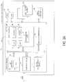
- FIG. 2 Ais a block diagram illustrating components of controller 102 in more detail.
- Controller 102includes a front end module 108 that interfaces with a host, a back end module 110 that interfaces with the one or more non-volatile memory die 104 , and various other modules that perform functions which will now be described in detail.
- a modulemay take the form of a packaged functional hardware unit designed for use with other components, a portion of a program code (e.g., software or firmware) executable by a (micro)processor or processing circuitry that usually performs a particular function of related functions, or a self-contained hardware or software component that interfaces with a larger system, for example.
- a program codee.g., software or firmware
- Modules of the controller 102may include a searching module 111 , which is discussed in more detail below, and can be implemented in hardware or software/firmware to extract various video frames from a video stream.
- the searching module 111can be configured to perform the algorithms and methods discussed below and shown in the attached drawings.
- a buffer manager/bus controller 114manages buffers in random access memory (RAM) 116 and controls the internal bus arbitration of controller 102 .
- a read only memory (ROM) 118stores system boot code. Although illustrated in FIG. 2 A as located separately from the controller 102 , in other embodiments one or both of the RAM 116 and ROM 118 may be located within the controller. In yet other embodiments, portions of RAM and ROM may be located both within the controller 102 and outside the controller.
- Front end module 108includes a host interface 120 and a physical layer interface (PHY) 122 that provide the electrical interface with the host or next level storage controller.
- PHYphysical layer interface
- the choice of the type of host interface 120can depend on the type of memory being used, Examples of host interfaces 120 include, but are not limited to, SATA, SATA Express, serially attached small computer system interface (SAS), Fibre Channel, universal serial bus (USB), PCIe, and NVMe.
- the host interface 120typically facilitates transfer for data, control signals, and timing signals.
- Back end module 110includes an error correction code (ECC) engine 124 that encodes the data bytes received from the host, and decodes and error corrects the data bytes read from the non-volatile memory.
- ECCerror correction code
- a command sequencer 126generates command sequences, such as program and erase command sequences, to be transmitted to non-volatile memory die 104 .
- a RAID (Redundant Array of Independent Drives) module 128manages generation of RAID parity and recovery of failed data. The RAID parity may be used as an additional level of integrity protection for the data being written into the memory device 104 . In some cases, the RAID module 128 may be a part of the FCC engine 124 .
- a memory interface 130provides the command sequences to non-volatile memory die 104 and receives status information from non-volatile memory die 104 .
- memory interface 130may be a double data rate (DDR) interface, such as a Toggle Mode 200 , 400 , or 800 interface.
- DDRdouble data rate
- a flash control layer 132controls the overall operation of back end module 110 .
- the storage system 100also includes other discrete components 140 , such as external electrical interfaces, external RAM, resistors, capacitors, or other components that may interface with controller 102 .
- other discrete components 140such as external electrical interfaces, external RAM, resistors, capacitors, or other components that may interface with controller 102 .
- one or more of the physical layer interface 122 , RAID module 128 , media management layer 138 and buffer management/bus controller 114are optional components that are not necessary in the controller 102 .
- FIG. 2 Bis a block diagram illustrating components of non-volatile memory die 104 in more detail.
- Non-volatile memory die 104includes peripheral circuitry 141 and non-volatile memory array 142 .
- Non-volatile memory array 142includes the non-volatile memory cells used to store data.
- the non-volatile memory cellsmay be any suitable non-volatile memory cells, including ReRAM, MRAM, PCM, NAND flash memory cells and/or NOR flash memory cells in a two dimensional and/or three dimensional configuration.
- Non-volatile memory die 104further includes a data cache 156 that caches data.
- Peripheral circuitry 141includes a state machine 152 that provides status information to the controller 102 .
- the flash control layer 132(which will be referred to herein as the flash translation layer (FTL) or, more generally, the “media management layer,” as the memory may not be flash) handles flash errors and interfaces with the host.
- the FTLwhich may be an algorithm in firmware, is responsible for the internals of memory management and translates writes from the host into writes to the memory 104 .
- the FTLmay be needed because the memory 104 may have limited endurance, may only be written in multiples of pages, and/or may not be written unless it is erased as a block.
- the FTLunderstands these potential limitations of the memory 104 , which may not be visible to the host. Accordingly, the FTL attempts to translate the writes from host into writes into the memory 104 .
- the FTLmay include a logical-to-physical address (L2P) map and allotted cache memory. In this way, the FTL translates logical block addresses (“LBAs”) from the host to physical addresses in the memory 104 .
- LBAslogical block addresses
- the FTLcan include other features, such as, but not limited to, power-off recovery (so that the data structures of the FTL can be recovered in the event of a sudden power loss) and wear leveling (so that the wear across memory blocks is even to prevent certain blocks from excessive wear, which would result in a greater chance of failure).
- a storage systemcan be used to store a data stream sent to it by a host.
- the datacan be stored in memory in the Moving Picture Experts Group Transport Stream (MPEG-TS) format.
- MPEG-TSMoving Picture Experts Group Transport Stream
- Searching for an object or a person of interest in the stored videois a major requirement of surveillance systems.
- the hostretrieves the entire stored video from the storage system and performs its own search to find the object or a person of interest. This is not optimum as it is a time- and resource-consuming process.
- the following embodimentscan be used to optimize the search process by taking advantage of the fact that, in many cases, the host knows the logical or time range to search for to find the person or object of interest.
- objectwill be used to refer to the person or thing that the host is searching for in the video. So, “object,” as used herein, can, but does not necessarily, refer to a person.
- the hostprovides the storage system 100 with an image of an object and a logical block address range of video data stored in the memory 104 , which can be a subset of the larger logical block address range of the video data.
- the imagecan be a single image or one of many images in a video clip.
- the storage system 100e.g., the controller 102 or the searching module 111 ) searches for the image of the object in the logical block address range and provides the host with possible hits from the search. Because it is the storage system 100 and not the host that is performing the search, these embodiments ease automation and minimize system latencies since the search algorithm runs inside the storage system 100 , thereby avoiding the need to transfer large amounts of irrelevant data to the host.
- the backend storage systemcan perform this activity, rather than trying to retrieve the entire data set to a host processor.
- These embodimentsmay be particularly beneficial with surveillance systems networked in a city, where authorities want to search for a wanted person's image.
- the video datais stored in the memory 104 in the Moving Picture Experts Group Transport Stream (MPEG-TS) format. It should be understood that this is merely an example, and other types of formats, frame types, and storage options can be used.
- MPEG-TSMoving Picture Experts Group Transport Stream
- I-framesintra-coded picture frames
- P-framespredicted picture frames
- B-framesbidirectional predicted picture frames
- I-framesare the least compressible but are independent in that they can be decoded without reference to other video frames.
- I-framecan be a complete image, such as a Joint Photographic Experts Group (JPEG) image file.
- JPEGJoint Photographic Experts Group
- P-framepredicted picture frame
- delta framecontains the changes in the image from the previous frame and requires reference to other video frames to be decompressed.
- P-framesare more compressible that I-frames.
- a bidirectional predicted picture frame (B-frame)contains differences between the current frame and both the preceding and following frames. Accordingly, B-frames provide the highest amount of data compression.
- an Instantaneous Decoder Refresh (IDR) frameis a group of I-frame slices.
- IDR frameall pictures in a reference buffer are marked as use for reference, and all subsequently-transmitted slices are decoded without reference to any frame decoded prior to the IDR frame. No frame after the IDR frame can reference any frame before it.
- IDR framesare used to avoid any distortions in the video when fast-forwarding.
- IDR framesare particularly useful for comparison to the reference image from the host because IDR frames are independently-decodable frames on par with an image. In short, a search algorithm only has to figure out if the object in the reference image is the same as or related to the object in another image and, if so, the extent of the similarity.
- FIG. 3is a block diagram of one suitable implementation.
- the host 50sends a reference image and logical range to the storage system 100 .
- the storage system 100internally decodes the stored video data within the host-provided logical range and retrieves a subset of frames (here, IDR frames) from the decoded video data.
- the distance between adjacent frames chosen for the matching operationcan be provided for by the search's quality of service (QoS) parameter and the bandwidth of the processor 102 .
- QoSquality of service
- the storage system 100attempts to match the subset of frames with the image provided by the host 50 .
- the storage system 100can use artificial intelligence or machine-learning techniques to match the host-provided image to the objects in different video IDR frames (multiple independent images) retrieved from provided data range.
- image recognition techniquesthat can be used to perform the search include those in U.S. Pat. No. 7,847,820 and U.S. Patent Application Publication No. US2006/0190419, which are hereby incorporated by reference. With improvement in pattern-matching algorithms, the scale of quality and automation increases with searches in surveillance systems.
- the storage system 100provides the host 50 with possible hits from the search and corresponding match percentages. For example, the storage system 100 can populate a table of hits with high to low matching rates, against the logical data range resulting from above steps, and send the populated table as feedback to the host 50 (e.g., to a surveillance application running on the host 50 ). The host 50 can then use this feedback to determine next steps, such as prioritizing the high-matching patterns for data retrieval and verification, data movement, subsequent processing, and other related decisions.
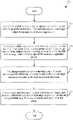
- FIG. 4illustrates the functional flow of a video search in an edge storage system.
- the host 50first sends a search request to the storage system 100 with the logical range of the stored data (act 410 ).
- the host 50also provides the image/object to be searched to the storage system 100 .
- the storage system 100then retrieves the data from the memory 104 and decodes the data (act 420 ).
- the storage system 100retrieves IDR frames present in the logical range and performs pattern-matching techniques on all or few of the IDR frames (e.g., based on the quality of service (QoS)) against the received image/object.
- QoSquality of service
- the storage system 100then creates a matching table with match percentages for all the matches it performed on the logical range and sends the table to the host 50 as search feedback (act 430 ). Finally, the host 50 evaluates the matching table and takes next steps, such as manual intervention of the search evaluation or going to the next set of logical data (e.g., if the search results were poor in the first place) (act 440 ).
- the host 50can send a video clip comprising a plurality of other images.
- the storage system 100can retrieve the reference object(s) from the input (IDRs through decode). Once the object(s) is/are retrieved, the above search process can be applied as many times as the number of reference images. The resultant two-dimensional feedback is passed to the host 50 at the end of processing. This strengthens the search mechanism to account for commonalities.
- any suitable type of memorycan be used.
- Semiconductor memory devicesinclude volatile memory devices, such as dynamic random access memory (“DRAM”) or static random access memory (“SRAM”) devices, non-volatile memory devices, such as resistive random access memory (“ReRAM”), electrically erasable programmable read only memory (“EEPROM”), flash memory (which can also be considered a subset of EEPROM), ferroelectric random access memory (“FRAM”), and magnetoresistive random access memory (“MRAM”), and other semiconductor elements capable of storing information.
- volatile memory devicessuch as dynamic random access memory (“DRAM”) or static random access memory (“SRAM”) devices
- non-volatile memory devicessuch as resistive random access memory (“ReRAM”), electrically erasable programmable read only memory (“EEPROM”), flash memory (which can also be considered a subset of EEPROM), ferroelectric random access memory (“FRAM”), and magnetoresistive random access memory (“MRAM”), and other semiconductor elements capable of storing information.
- ReRAMresistive random access memory
- the memory devicescan be formed from passive and/or active elements, in any combinations.
- passive semiconductor memory elementsinclude ReRAM device elements, which in some embodiments include a resistivity switching storage element, such as an anti-fuse, phase change material, etc., and optionally a steering element, such as a diode, etc.
- active semiconductor memory elementsinclude EEPROM and flash memory device elements, which in some embodiments include elements containing a charge storage region, such as a floating gate, conductive nanoparticles, or a charge storage dielectric material.
- Multiple memory elementsmay be configured so that they are connected in series or so that each element is individually accessible.
- flash memory devices in a NAND configurationtypically contain memory elements connected in series.
- a NAND memory arraymay be configured so that the array is composed of multiple strings of memory in which a string is composed of multiple memory elements sharing a single bit line and accessed as a group.
- memory elementsmay be configured so that each element is individually accessible, e.g., a NOR memory array.
- NAND and NOR memory configurationsare examples, and memory elements may be otherwise configured.
- the semiconductor memory elements located within and/or over a substratemay be arranged in two or three dimensions, such as a two dimensional memory structure or a three dimensional memory structure.
- the semiconductor memory elementsare arranged in a single plane or a single memory device level.
- memory elementsare arranged in a plane (e.g., in an x-z direction plane) which extends substantially parallel to a major surface of a substrate that supports the memory elements.
- the substratemay be a wafer over or in which the layer of the memory elements are formed or it may be a carrier substrate which is attached to the memory elements after they are formed.
- the substratemay include a semiconductor such as silicon.
- the memory elementsmay be arranged in the single memory device level in an ordered array, such as in a plurality of rows and/or columns. However, the memory elements may be arrayed in non-regular or non-orthogonal configurations.
- the memory elementsmay each have two or more electrodes or contact lines, such as bit lines and wordlines.
- a three dimensional memory arrayis arranged so that memory elements occupy multiple planes or multiple memory device levels, thereby forming a structure in three dimensions (i.e., in the x, y and z directions, where the y direction is substantially perpendicular and the x and z directions are substantially parallel to the major surface of the substrate).
- a three dimensional memory structuremay be vertically arranged as a stack of multiple two dimensional memory device levels.
- a three dimensional memory arraymay be arranged as multiple vertical columns (e.g., columns extending substantially perpendicular to the major surface of the substrate, i.e., in the y direction) with each column having multiple memory elements in each column.
- the columnsmay be arranged in a two dimensional configuration, e.g., in an x-z plane, resulting in a three dimensional arrangement of memory elements with elements on multiple vertically stacked memory planes.
- Other configurations of memory elements in three dimensionscan also constitute a three dimensional memory array.
- the memory elementsmay be coupled together to form a NAND string within a single horizontal (e.g., x-z) memory device levels.
- the memory elementsmay be coupled together to form a vertical NAND string that traverses across multiple horizontal memory device levels.
- Other three dimensional configurationscan be envisioned wherein some NAND strings contain memory elements in a single memory level while other strings contain memory elements which span through multiple memory levels.
- Three dimensional memory arraysmay also be designed in a NOR configuration and in a ReRAM configuration.
- a monolithic three dimensional memory arraytypically, one or more memory device levels are formed above a single substrate.
- the monolithic three dimensional memory arraymay also have one or more memory layers at least partially within the single substrate.
- the substratemay include a semiconductor such as silicon.
- the layers constituting each memory device level of the arrayare typically formed on the layers of the underlying memory device levels of the array.
- layers of adjacent memory device levels of a monolithic three dimensional memory arraymay be shared or have intervening layers between memory device levels.
- non-monolithic stacked memoriescan be constructed by forming memory levels on separate substrates and then stacking the memory levels atop each other. The substrates may be thinned or removed from the memory device levels before stacking, but as the memory device levels are initially formed over separate substrates, the resulting memory arrays are not monolithic three dimensional memory arrays. Further, multiple two dimensional memory arrays or three dimensional memory arrays (monolithic or non-monolithic) may be formed on separate chips and then packaged together to form a stacked-chip memory device.
- Associated circuitryis typically required for operation of the memory elements and for communication with the memory elements.
- memory devicesmay have circuitry used for controlling and driving memory elements to accomplish functions such as programming and reading.
- This associated circuitrymay be on the same substrate as the memory elements and/or on a separate substrate.
- a controller for memory read-write operationsmay be located on a separate controller chip and/or on the same substrate as the memory elements.
Landscapes
- Engineering & Computer Science (AREA)
- Theoretical Computer Science (AREA)
- General Engineering & Computer Science (AREA)
- Data Mining & Analysis (AREA)
- Physics & Mathematics (AREA)
- General Physics & Mathematics (AREA)
- Software Systems (AREA)
- Multimedia (AREA)
- Computing Systems (AREA)
- Mathematical Physics (AREA)
- Evolutionary Computation (AREA)
- Computational Linguistics (AREA)
- Artificial Intelligence (AREA)
- Databases & Information Systems (AREA)
- Library & Information Science (AREA)
- Computer Vision & Pattern Recognition (AREA)
- Medical Informatics (AREA)
- Information Retrieval, Db Structures And Fs Structures Therefor (AREA)
Abstract
Description
Claims (20)
Priority Applications (2)
| Application Number | Priority Date | Filing Date | Title |
|---|---|---|---|
| US16/781,717US11562018B2 (en) | 2020-02-04 | 2020-02-04 | Storage system and method for optimized surveillance search |
| PCT/US2020/037903WO2021158253A1 (en) | 2020-02-04 | 2020-06-16 | Storage system and method for optimized surveillance search |
Applications Claiming Priority (1)
| Application Number | Priority Date | Filing Date | Title |
|---|---|---|---|
| US16/781,717US11562018B2 (en) | 2020-02-04 | 2020-02-04 | Storage system and method for optimized surveillance search |
Publications (2)
| Publication Number | Publication Date |
|---|---|
| US20210240764A1 US20210240764A1 (en) | 2021-08-05 |
| US11562018B2true US11562018B2 (en) | 2023-01-24 |
Family
ID=77062666
Family Applications (1)
| Application Number | Title | Priority Date | Filing Date |
|---|---|---|---|
| US16/781,717Active2040-11-03US11562018B2 (en) | 2020-02-04 | 2020-02-04 | Storage system and method for optimized surveillance search |
Country Status (2)
| Country | Link |
|---|---|
| US (1) | US11562018B2 (en) |
| WO (1) | WO2021158253A1 (en) |
Families Citing this family (1)
| Publication number | Priority date | Publication date | Assignee | Title |
|---|---|---|---|---|
| US11523145B2 (en)* | 2021-01-04 | 2022-12-06 | Western Digital Technologies, Inc. | Data storage device and method for real-time data locking in surveillance storage |
Citations (69)
| Publication number | Priority date | Publication date | Assignee | Title |
|---|---|---|---|---|
| US5099150A (en) | 1989-09-29 | 1992-03-24 | Sgs-Thomson Microelectronics, Inc. | Circuit block for programmable logic devices, configurable as a user-writable memory or a logic circuit |
| US6002802A (en) | 1995-10-27 | 1999-12-14 | Kabushiki Kaisha Toshiba | Video encoding and decoding apparatus |
| US20010044856A1 (en) | 2000-05-16 | 2001-11-22 | Sun Microsystems, Inc. | Dynamic adaptive tenuring of objects |
| EP1173020A2 (en) | 2000-07-10 | 2002-01-16 | Mitsubishi Denki Kabushiki Kaisha | Networked surveillance and control system |
| US6542075B2 (en) | 2000-09-28 | 2003-04-01 | Vigilos, Inc. | System and method for providing configurable security monitoring utilizing an integrated information portal |
| US20030093801A1 (en) | 2001-11-15 | 2003-05-15 | Chia-Wen Lin | Methods and systems for video streaming with VCR functionality |
| US20030225746A1 (en) | 2002-05-31 | 2003-12-04 | Braun Richard A. | Systems and methods for tracking assets |
| US6768661B2 (en) | 2002-06-27 | 2004-07-27 | Matrix Semiconductor, Inc. | Multiple-mode memory and method for forming same |
| US20060190419A1 (en) | 2005-02-22 | 2006-08-24 | Bunn Frank E | Video surveillance data analysis algorithms, with local and network-shared communications for facial, physical condition, and intoxication recognition, fuzzy logic intelligent camera system |
| US20080310736A1 (en) | 2007-06-15 | 2008-12-18 | Microsoft Corporation | Smart visual comparison of graphical user interfaces |
| US7631327B2 (en) | 2001-08-08 | 2009-12-08 | Accenture Global Services Gmbh | Enhanced custom content television |
| US20090319255A1 (en) | 2008-06-23 | 2009-12-24 | Sun Microsystems, Inc. | Maximizing throughput for a garbage collector |
| EP2141928A1 (en) | 2008-06-30 | 2010-01-06 | Thomson Licensing S.A. | Device and method for analysing an encoded image |
| US20100074594A1 (en)* | 2008-09-18 | 2010-03-25 | Panasonic Corporation | Stereoscopic video playback device and stereoscopic video display device |
| US7760230B2 (en) | 2004-03-16 | 2010-07-20 | 3Vr Security, Inc. | Method for automatically reducing stored data in a surveillance system |
| JP2010161740A (en) | 2009-01-09 | 2010-07-22 | Canon Inc | Image coding device and image coding method |
| US20100272411A1 (en) | 2009-04-22 | 2010-10-28 | Fujitsu Limited | Playback apparatus and playback method |
| US20100284612A1 (en) | 2008-01-17 | 2010-11-11 | Koninklijke Philips Electronics N.V. | Flash detection |
| US20110258375A1 (en) | 2010-04-15 | 2011-10-20 | Farzad Khosrowpour | Method and Apparatus for In-Place Hold and Preservation Operation on Objects in Content Addressable Storage |
| US20120082209A1 (en)* | 2010-10-05 | 2012-04-05 | Ruijia Li | Method and apparatus for dynamically adjusting video quality |
| US20120102297A1 (en) | 2010-10-25 | 2012-04-26 | Seagate Technology Llc | Storing Corresponding Data Units in a Common Storage Unit |
| US20120210232A1 (en)* | 2011-02-16 | 2012-08-16 | Wang Xiaohuan C | Rate Conform Operation for a Media-Editing Application |
| US8412783B2 (en) | 2002-06-25 | 2013-04-02 | International Business Machines Corporation | Personal video recording with machine learning for messaging |
| US8516019B2 (en) | 2011-10-03 | 2013-08-20 | Oracle America, Inc. | Time-based object aging for generational garbage collectors |
| US20130254611A1 (en) | 2012-03-23 | 2013-09-26 | Qualcomm Incorporated | Recovering data in multimedia file segments |
| US20140075096A1 (en) | 2012-09-07 | 2014-03-13 | Hiroaki Tanaka | Storage device and method for controlling the same |
| US8676027B2 (en) | 2010-07-16 | 2014-03-18 | Axis Ab | Method for event initiated video capturing and a video camera for capture event initiated video |
| US8725940B2 (en) | 2010-02-27 | 2014-05-13 | Cleversafe, Inc. | Distributedly storing raid data in a raid memory and a dispersed storage network memory |
| US8825721B2 (en) | 2011-10-03 | 2014-09-02 | Oracle International Corporation | Time-based object aging for generational garbage collectors |
| US20150012671A1 (en) | 2013-07-08 | 2015-01-08 | Jeong-Woo Park | Storage systems and ufs systems configured to change interface mode in active state |
| US9037921B1 (en) | 2012-03-29 | 2015-05-19 | Amazon Technologies, Inc. | Variable drive health determination and data placement |
| US20150237351A1 (en) | 2014-02-18 | 2015-08-20 | Penne Lee | Techniques for inclusion of region of interest indications in compressed video data |
| US20150261452A1 (en) | 2014-03-12 | 2015-09-17 | Samsung Electronics Co., Ltd. | Memory device and controlling method of the same |
| WO2015154549A1 (en) | 2014-08-11 | 2015-10-15 | 中兴通讯股份有限公司 | Data processing method and device |
| US9215423B2 (en) | 2009-03-30 | 2015-12-15 | Time Warner Cable Enterprises Llc | Recommendation engine apparatus and methods |
| US20160211003A1 (en) | 2015-01-16 | 2016-07-21 | Hangzhou Hikvision Digital Technology Co., Ltd. | Systems, Devices and Methods for Video Storage |
| US9414109B2 (en) | 2011-08-31 | 2016-08-09 | Tivo Inc. | Multimedia program recording schedule manager |
| US9489580B2 (en) | 2014-07-07 | 2016-11-08 | Google Inc. | Method and system for cluster-based video monitoring and event categorization |
| US20160345009A1 (en) | 2015-05-19 | 2016-11-24 | ScaleFlux | Accelerating image analysis and machine learning through in-flash image preparation and pre-processing |
| WO2017134110A1 (en) | 2016-02-02 | 2017-08-10 | Fraunhofer-Gesellschaft zur Förderung der angewandten Forschung e.V. | Scene section and region of interest handling in video streaming |
| US9781479B2 (en) | 2016-02-29 | 2017-10-03 | Rovi Guides, Inc. | Methods and systems of recommending media assets to users based on content of other media assets |
| US20170285949A1 (en) | 2016-04-02 | 2017-10-05 | Intel Corporation | Search and replace operations in a memory device |
| US20170285968A1 (en) | 2016-04-04 | 2017-10-05 | MemRay Corporation | Flash-based accelerator and computing device including the same |
| US9836248B2 (en) | 2014-10-30 | 2017-12-05 | ScaleFlux | In-memory data compression complementary to host data compression |
| KR20180015101A (en) | 2017-10-30 | 2018-02-12 | 명홍철 | Method and apparatus of extracting region-of-interest video in source video |
| US20180068540A1 (en) | 2015-05-12 | 2018-03-08 | Apical Ltd | Image processing method |
| US10007442B2 (en) | 2014-08-20 | 2018-06-26 | Sandisk Technologies Llc | Methods, systems, and computer readable media for automatically deriving hints from accesses to a storage device and from file system metadata and for optimizing utilization of the storage device based on the hints |
| US20180189635A1 (en) | 2016-12-30 | 2018-07-05 | Samsung Electronics Co., Ltd. | Method and apparatus for supporting machine learning algorithms and data pattern matching in ethernet ssd |
| US20180270499A1 (en) | 2017-03-15 | 2018-09-20 | Arm Limited | Video data processing system |
| US20180267720A1 (en) | 2017-03-14 | 2018-09-20 | International Business Machines Corporation | Techniques for selecting storage blocks for garbage collection based on longevity information |
| US10095445B2 (en) | 2016-03-29 | 2018-10-09 | Western Digital Technologies, Inc. | Systems and methods for offloading processing from a host to storage processing units using an interconnect network |
| US20180295367A1 (en) | 2017-04-10 | 2018-10-11 | Intel Corporation | Technology to accelerate scene change detection and achieve adaptive content display |
| KR20180114972A (en) | 2017-04-11 | 2018-10-22 | 에스케이하이닉스 주식회사 | Data storage device and operating method thereof |
| US20180341410A1 (en) | 2017-03-24 | 2018-11-29 | Western Digital Technologies, Inc. | System and method for adaptive early completion posting using controller memory buffer |
| US20180357074A1 (en)* | 2017-06-13 | 2018-12-13 | Western Digital Technologies Inc. | Method and system for user experience event processing and analysis |
| US20190043201A1 (en) | 2017-12-28 | 2019-02-07 | Christina R. Strong | Analytic image format for visual computing |
| US10228854B2 (en) | 2014-08-20 | 2019-03-12 | Sandisk Technologies Llc | Storage devices and methods for optimizing use of storage devices based on storage device parsing of file system metadata in host write operations |
| US20190079677A1 (en) | 2017-09-14 | 2019-03-14 | Samsung Electronics Co., Ltd. | Host-based and client-based command scheduling in large bandwidth memory systems |
| US20190104341A1 (en) | 2017-09-29 | 2019-04-04 | International Business Machines Corporation | Cognitive digital video filtering based on user preferences |
| US20190163622A1 (en) | 2017-11-30 | 2019-05-30 | Innodisk Corporation | Estimation method for data access performance |
| US20190187936A1 (en) | 2017-12-20 | 2019-06-20 | Seagate Technology Llc | Shingled magnetic recording trim operation |
| US20190246130A1 (en) | 2018-02-08 | 2019-08-08 | Samsung Electronics Co., Ltd. | Progressive compressed domain computer vision and deep learning systems |
| US20190243754A1 (en) | 2018-02-06 | 2019-08-08 | Western Digital Technologies, Inc. | Flash fast program mode for high definition video recording and high resolution camera burst mode recording |
| US20190294730A1 (en) | 2014-11-19 | 2019-09-26 | Western Digital Technologies, Inc. | Device-based search in data storage device |
| US20190313083A1 (en)* | 2018-04-06 | 2019-10-10 | Zspace, Inc. | Replacing 2D Images with 3D Images |
| US20190379926A1 (en) | 2018-06-06 | 2019-12-12 | Microsoft Technology Licensing, Llc | Method of optimizing media used to display moving images |
| US20200145701A1 (en) | 2016-12-30 | 2020-05-07 | Tivo Solutions Inc. | Advanced trick-play modes for streaming video |
| US20210149946A1 (en)* | 2019-11-19 | 2021-05-20 | Lenovo (Singapore) Pte. Ltd. | Reverse image search using portion of image but not entirety of image |
| US20210385532A1 (en)* | 2018-04-25 | 2021-12-09 | Roku, Inc. | Server-side scene change content stitching |
- 2020
- 2020-02-04USUS16/781,717patent/US11562018B2/enactiveActive
- 2020-06-16WOPCT/US2020/037903patent/WO2021158253A1/ennot_activeCeased
Patent Citations (71)
| Publication number | Priority date | Publication date | Assignee | Title |
|---|---|---|---|---|
| US5099150A (en) | 1989-09-29 | 1992-03-24 | Sgs-Thomson Microelectronics, Inc. | Circuit block for programmable logic devices, configurable as a user-writable memory or a logic circuit |
| US6002802A (en) | 1995-10-27 | 1999-12-14 | Kabushiki Kaisha Toshiba | Video encoding and decoding apparatus |
| US20010044856A1 (en) | 2000-05-16 | 2001-11-22 | Sun Microsystems, Inc. | Dynamic adaptive tenuring of objects |
| EP1173020A2 (en) | 2000-07-10 | 2002-01-16 | Mitsubishi Denki Kabushiki Kaisha | Networked surveillance and control system |
| EP1173020A3 (en) | 2000-07-10 | 2002-07-31 | Mitsubishi Denki Kabushiki Kaisha | Networked surveillance and control system |
| US6542075B2 (en) | 2000-09-28 | 2003-04-01 | Vigilos, Inc. | System and method for providing configurable security monitoring utilizing an integrated information portal |
| US7631327B2 (en) | 2001-08-08 | 2009-12-08 | Accenture Global Services Gmbh | Enhanced custom content television |
| US20030093801A1 (en) | 2001-11-15 | 2003-05-15 | Chia-Wen Lin | Methods and systems for video streaming with VCR functionality |
| US20030225746A1 (en) | 2002-05-31 | 2003-12-04 | Braun Richard A. | Systems and methods for tracking assets |
| US8412783B2 (en) | 2002-06-25 | 2013-04-02 | International Business Machines Corporation | Personal video recording with machine learning for messaging |
| US6768661B2 (en) | 2002-06-27 | 2004-07-27 | Matrix Semiconductor, Inc. | Multiple-mode memory and method for forming same |
| US7760230B2 (en) | 2004-03-16 | 2010-07-20 | 3Vr Security, Inc. | Method for automatically reducing stored data in a surveillance system |
| US7847820B2 (en) | 2004-03-16 | 2010-12-07 | 3Vr Security, Inc. | Intelligent event determination and notification in a surveillance system |
| US20060190419A1 (en) | 2005-02-22 | 2006-08-24 | Bunn Frank E | Video surveillance data analysis algorithms, with local and network-shared communications for facial, physical condition, and intoxication recognition, fuzzy logic intelligent camera system |
| US20080310736A1 (en) | 2007-06-15 | 2008-12-18 | Microsoft Corporation | Smart visual comparison of graphical user interfaces |
| US20100284612A1 (en) | 2008-01-17 | 2010-11-11 | Koninklijke Philips Electronics N.V. | Flash detection |
| US20090319255A1 (en) | 2008-06-23 | 2009-12-24 | Sun Microsystems, Inc. | Maximizing throughput for a garbage collector |
| EP2141928A1 (en) | 2008-06-30 | 2010-01-06 | Thomson Licensing S.A. | Device and method for analysing an encoded image |
| US20100074594A1 (en)* | 2008-09-18 | 2010-03-25 | Panasonic Corporation | Stereoscopic video playback device and stereoscopic video display device |
| JP2010161740A (en) | 2009-01-09 | 2010-07-22 | Canon Inc | Image coding device and image coding method |
| US9215423B2 (en) | 2009-03-30 | 2015-12-15 | Time Warner Cable Enterprises Llc | Recommendation engine apparatus and methods |
| US20100272411A1 (en) | 2009-04-22 | 2010-10-28 | Fujitsu Limited | Playback apparatus and playback method |
| US8725940B2 (en) | 2010-02-27 | 2014-05-13 | Cleversafe, Inc. | Distributedly storing raid data in a raid memory and a dispersed storage network memory |
| US20110258375A1 (en) | 2010-04-15 | 2011-10-20 | Farzad Khosrowpour | Method and Apparatus for In-Place Hold and Preservation Operation on Objects in Content Addressable Storage |
| US8676027B2 (en) | 2010-07-16 | 2014-03-18 | Axis Ab | Method for event initiated video capturing and a video camera for capture event initiated video |
| US20120082209A1 (en)* | 2010-10-05 | 2012-04-05 | Ruijia Li | Method and apparatus for dynamically adjusting video quality |
| US20120102297A1 (en) | 2010-10-25 | 2012-04-26 | Seagate Technology Llc | Storing Corresponding Data Units in a Common Storage Unit |
| US20120210232A1 (en)* | 2011-02-16 | 2012-08-16 | Wang Xiaohuan C | Rate Conform Operation for a Media-Editing Application |
| US9414109B2 (en) | 2011-08-31 | 2016-08-09 | Tivo Inc. | Multimedia program recording schedule manager |
| US8516019B2 (en) | 2011-10-03 | 2013-08-20 | Oracle America, Inc. | Time-based object aging for generational garbage collectors |
| US8825721B2 (en) | 2011-10-03 | 2014-09-02 | Oracle International Corporation | Time-based object aging for generational garbage collectors |
| US20130254611A1 (en) | 2012-03-23 | 2013-09-26 | Qualcomm Incorporated | Recovering data in multimedia file segments |
| US9037921B1 (en) | 2012-03-29 | 2015-05-19 | Amazon Technologies, Inc. | Variable drive health determination and data placement |
| US20140075096A1 (en) | 2012-09-07 | 2014-03-13 | Hiroaki Tanaka | Storage device and method for controlling the same |
| US20150012671A1 (en) | 2013-07-08 | 2015-01-08 | Jeong-Woo Park | Storage systems and ufs systems configured to change interface mode in active state |
| US20150237351A1 (en) | 2014-02-18 | 2015-08-20 | Penne Lee | Techniques for inclusion of region of interest indications in compressed video data |
| US20150261452A1 (en) | 2014-03-12 | 2015-09-17 | Samsung Electronics Co., Ltd. | Memory device and controlling method of the same |
| US9489580B2 (en) | 2014-07-07 | 2016-11-08 | Google Inc. | Method and system for cluster-based video monitoring and event categorization |
| WO2015154549A1 (en) | 2014-08-11 | 2015-10-15 | 中兴通讯股份有限公司 | Data processing method and device |
| US10228854B2 (en) | 2014-08-20 | 2019-03-12 | Sandisk Technologies Llc | Storage devices and methods for optimizing use of storage devices based on storage device parsing of file system metadata in host write operations |
| US10007442B2 (en) | 2014-08-20 | 2018-06-26 | Sandisk Technologies Llc | Methods, systems, and computer readable media for automatically deriving hints from accesses to a storage device and from file system metadata and for optimizing utilization of the storage device based on the hints |
| US9836248B2 (en) | 2014-10-30 | 2017-12-05 | ScaleFlux | In-memory data compression complementary to host data compression |
| US20190294730A1 (en) | 2014-11-19 | 2019-09-26 | Western Digital Technologies, Inc. | Device-based search in data storage device |
| US20160211003A1 (en) | 2015-01-16 | 2016-07-21 | Hangzhou Hikvision Digital Technology Co., Ltd. | Systems, Devices and Methods for Video Storage |
| US20180068540A1 (en) | 2015-05-12 | 2018-03-08 | Apical Ltd | Image processing method |
| US20160345009A1 (en) | 2015-05-19 | 2016-11-24 | ScaleFlux | Accelerating image analysis and machine learning through in-flash image preparation and pre-processing |
| WO2017134110A1 (en) | 2016-02-02 | 2017-08-10 | Fraunhofer-Gesellschaft zur Förderung der angewandten Forschung e.V. | Scene section and region of interest handling in video streaming |
| US9781479B2 (en) | 2016-02-29 | 2017-10-03 | Rovi Guides, Inc. | Methods and systems of recommending media assets to users based on content of other media assets |
| US10095445B2 (en) | 2016-03-29 | 2018-10-09 | Western Digital Technologies, Inc. | Systems and methods for offloading processing from a host to storage processing units using an interconnect network |
| US20170285949A1 (en) | 2016-04-02 | 2017-10-05 | Intel Corporation | Search and replace operations in a memory device |
| US20170285968A1 (en) | 2016-04-04 | 2017-10-05 | MemRay Corporation | Flash-based accelerator and computing device including the same |
| US20200145701A1 (en) | 2016-12-30 | 2020-05-07 | Tivo Solutions Inc. | Advanced trick-play modes for streaming video |
| US20180189635A1 (en) | 2016-12-30 | 2018-07-05 | Samsung Electronics Co., Ltd. | Method and apparatus for supporting machine learning algorithms and data pattern matching in ethernet ssd |
| US20180267720A1 (en) | 2017-03-14 | 2018-09-20 | International Business Machines Corporation | Techniques for selecting storage blocks for garbage collection based on longevity information |
| US20180270499A1 (en) | 2017-03-15 | 2018-09-20 | Arm Limited | Video data processing system |
| US20180341410A1 (en) | 2017-03-24 | 2018-11-29 | Western Digital Technologies, Inc. | System and method for adaptive early completion posting using controller memory buffer |
| US20180295367A1 (en) | 2017-04-10 | 2018-10-11 | Intel Corporation | Technology to accelerate scene change detection and achieve adaptive content display |
| KR20180114972A (en) | 2017-04-11 | 2018-10-22 | 에스케이하이닉스 주식회사 | Data storage device and operating method thereof |
| US20180357074A1 (en)* | 2017-06-13 | 2018-12-13 | Western Digital Technologies Inc. | Method and system for user experience event processing and analysis |
| US20190079677A1 (en) | 2017-09-14 | 2019-03-14 | Samsung Electronics Co., Ltd. | Host-based and client-based command scheduling in large bandwidth memory systems |
| US20190104341A1 (en) | 2017-09-29 | 2019-04-04 | International Business Machines Corporation | Cognitive digital video filtering based on user preferences |
| KR20180015101A (en) | 2017-10-30 | 2018-02-12 | 명홍철 | Method and apparatus of extracting region-of-interest video in source video |
| US20190163622A1 (en) | 2017-11-30 | 2019-05-30 | Innodisk Corporation | Estimation method for data access performance |
| US20190187936A1 (en) | 2017-12-20 | 2019-06-20 | Seagate Technology Llc | Shingled magnetic recording trim operation |
| US20190043201A1 (en) | 2017-12-28 | 2019-02-07 | Christina R. Strong | Analytic image format for visual computing |
| US20190243754A1 (en) | 2018-02-06 | 2019-08-08 | Western Digital Technologies, Inc. | Flash fast program mode for high definition video recording and high resolution camera burst mode recording |
| US20190246130A1 (en) | 2018-02-08 | 2019-08-08 | Samsung Electronics Co., Ltd. | Progressive compressed domain computer vision and deep learning systems |
| US20190313083A1 (en)* | 2018-04-06 | 2019-10-10 | Zspace, Inc. | Replacing 2D Images with 3D Images |
| US20210385532A1 (en)* | 2018-04-25 | 2021-12-09 | Roku, Inc. | Server-side scene change content stitching |
| US20190379926A1 (en) | 2018-06-06 | 2019-12-12 | Microsoft Technology Licensing, Llc | Method of optimizing media used to display moving images |
| US20210149946A1 (en)* | 2019-11-19 | 2021-05-20 | Lenovo (Singapore) Pte. Ltd. | Reverse image search using portion of image but not entirety of image |
Non-Patent Citations (29)
| Title |
|---|
| "Data differencing"; Wikipedia entry; downloaded from the Internet at https://en.wikipedia.org/wiki/Data_differencing on Aug. 6, 2019; 3 pages. |
| "H.264/MPEG-4 AVC"; Wikipedia entry; downloaded from the Internet at https://en.wikipedia.org/wiki/H.264/MPEG-4_AVC on Aug. 6, 2019; 18 pages. |
| "MPEG transport stream"; Wikipedia entry; downloaded from the Internet at https://en.wikipedia.org/wiki/MPEG_transport_stream on Jul. 22, 2019; 6 pages. |
| "Trick mode"; Wikipedia entry; downloaded from the Internet at https://en.wikipedia.org/wiki/Trick_mode on Jul. 22, 2019; 1 page. |
| "Video compression picture types"; Wikipedia entry; downloaded from the Internet at https://en.wikipedia.org/wiki/Video _compression_picture_types on Aug. 6, 2019; 4 pages. |
| European Search Report in EP Application No. 19216071.1, dated Feb. 7, 2020, 8 pages. |
| Final Office Action dated Jul. 13, 2021 for U.S. Appl. No. 16/899,262. |
| Final Office Action dated Mar. 17, 2022 for U.S. Appl. No. 16/781,688. |
| International Search Report dated Aug. 26, 2020 for International Application No. PCT/US2020/024852. |
| International Search Report dated Aug. 5, 2020 for International Application No. PCT/US2020/037897. |
| International Search Report dated Jul. 6, 2021 for International Application No. PCT/US2020/037903. |
| Non-final Office Action dated Aug. 12, 2021 for U.S. Appl. No. 16/818,452. |
| Non-final Office Action dated Jul. 15, 2021 for U.S. Appl. No. 16/781,688. |
| Office Action in U.S. Appl. No. 15/929,090, dated Feb. 20, 2020, 17 pages. |
| Office Action in U.S. Appl. No. 15/929,090, dated Sep. 27, 2019, 16 pages. |
| Office Action in U.S. Appl. No. 16/781,688, dated Apr. 2, 2021, 26 pages. |
| Singh, S. et al.; "Real-Time Implementation of Change Detection for Automated Video Surveillance System"; Research article; ISRN Electronics, vol. 2013, Article ID 691930; 5 pages; Jun. 11, 2013. |
| U.S. Appl. No. 15/929,090, filed Jan. 11, 2019. |
| U.S. Appl. No. 15/929,090, filed Jan. 2019, Muthiah et al. |
| U.S. Appl. No. 16/670,112, filed Oct. 2019, Muthiah et al. |
| U.S. Appl. No. 16/708,091, filed Dec. 2019, Muthiah et al. |
| U.S. Appl. No. 16/708,091, filed Dec. 9, 2019 entitled "Storage System and Method for Video Frame Segregation to Optimize Storage." |
| U.S. Appl. No. 16/781,688, filed Feb. 4, 2020 entitled "Storage System and Method for Automatic Data Phasing." |
| U.S. Appl. No. 16/781,717, filed Feb. 4, 2020 entitled "Storage System and Method for Optimized Surveillance Search." |
| U.S. Appl. No. 16/818,452, filed Mar. 2020, Muthiah et al. |
| Written Opinion dated Aug. 26, 2020 for International Application No. PCT/US2020/024852. |
| Written Opinion dated Aug. 5, 2020 for International Application No. PCT/US2020/037897. |
| Written Opinion dated Jul. 6, 2021 for International Application No. PCT/US2020/037903. |
| XuanHua Shi et al., "Deca: A Garbage Collection Optimizer for In-Memory Data Processing", <https://di.acm.org/doi/full Html/10.1145/3310361>, ACM Trans. Comput. Syst., vol. 36, No. 1, Article 3, Publication date: Mar. 2019. DOI: https://doi.org/10.1145/3310361 (Year: 2019), 66 pages. |
Also Published As
| Publication number | Publication date |
|---|---|
| US20210240764A1 (en) | 2021-08-05 |
| WO2021158253A1 (en) | 2021-08-12 |
Similar Documents
| Publication | Publication Date | Title |
|---|---|---|
| US10841645B1 (en) | Storage system and method for video frame segregation to optimize storage | |
| US20210240612A1 (en) | Storage System and Method for Automatic Data Phasing | |
| US20230090319A1 (en) | Storage System and Method for Prediction-Based Pre-Erase of Blocks to Improve Sequential Performance | |
| US20220404998A1 (en) | Data Storage Device and Method for Progressive Fading for Video Surveillance Systems | |
| US11562018B2 (en) | Storage system and method for optimized surveillance search | |
| US20240143227A1 (en) | Data Storage Device and Method for Reducing Flush Latency | |
| US12067268B2 (en) | Data storage device and method for dynamic prediction of random read with low memory consumption | |
| US11328511B2 (en) | Storage system and method for improved playback analysis | |
| US11550487B2 (en) | Data storage device and method for enabling endurance re-evaluation | |
| US12363312B2 (en) | Storage system and method for storage management in multi-channel, variable-bit-rate systems | |
| US11240540B2 (en) | Storage system and method for frame trimming to optimize network bandwidth | |
| US20210400302A1 (en) | Storage System and Method for Object Monitoring | |
| US11523145B2 (en) | Data storage device and method for real-time data locking in surveillance storage | |
| US12250417B2 (en) | Data storage device and method for selecting a data recovery mechanism based on a video frame position | |
| US11849186B1 (en) | Data storage device and method for enabling metadata-based seek points for media access | |
| US11651027B2 (en) | Data storage device and method for object detection and tagging quality of service based on storage workload | |
| US11429663B2 (en) | Storage system and method for host-assisted memory block color coding for faster media search | |
| US11783866B2 (en) | Data storage device and method for legitimized data transfer | |
| US11650757B2 (en) | Storage system and method for time-based data retrieval | |
| US12254204B2 (en) | Data storage device and method for host-controlled data compression | |
| US11494101B2 (en) | Storage system and method for time-duration-based efficient block management and memory access | |
| US11983442B2 (en) | Data storage device and method for multi-level conditional prediction of future random read commands | |
| US20240420791A1 (en) | Data Storage Device and Method for Host-Managed Data Integrity |
Legal Events
| Date | Code | Title | Description |
|---|---|---|---|
| AS | Assignment | Owner name:WESTERN DIGITAL TECHNOLOGIES, INC., CALIFORNIA Free format text:ASSIGNMENT OF ASSIGNORS INTEREST;ASSIGNOR:MUTHIAH, RAMANATHAN;REEL/FRAME:051716/0905 Effective date:20200204 | |
| FEPP | Fee payment procedure | Free format text:ENTITY STATUS SET TO UNDISCOUNTED (ORIGINAL EVENT CODE: BIG.); ENTITY STATUS OF PATENT OWNER: LARGE ENTITY | |
| AS | Assignment | Owner name:JPMORGAN CHASE BANK, N.A., AS AGENT, ILLINOIS Free format text:SECURITY INTEREST;ASSIGNOR:WESTERN DIGITAL TECHNOLOGIES, INC.;REEL/FRAME:053482/0453 Effective date:20200511 | |
| AS | Assignment | Owner name:WESTERN DIGITAL TECHNOLOGIES, INC., CALIFORNIA Free format text:RELEASE OF SECURITY INTEREST AT REEL 053482 FRAME 0453;ASSIGNOR:JPMORGAN CHASE BANK, N.A.;REEL/FRAME:058966/0279 Effective date:20220203 | |
| STPP | Information on status: patent application and granting procedure in general | Free format text:NON FINAL ACTION MAILED | |
| STPP | Information on status: patent application and granting procedure in general | Free format text:RESPONSE TO NON-FINAL OFFICE ACTION ENTERED AND FORWARDED TO EXAMINER | |
| STPP | Information on status: patent application and granting procedure in general | Free format text:NOTICE OF ALLOWANCE MAILED -- APPLICATION RECEIVED IN OFFICE OF PUBLICATIONS | |
| STPP | Information on status: patent application and granting procedure in general | Free format text:PUBLICATIONS -- ISSUE FEE PAYMENT VERIFIED | |
| STCF | Information on status: patent grant | Free format text:PATENTED CASE | |
| AS | Assignment | Owner name:JPMORGAN CHASE BANK, N.A., ILLINOIS Free format text:PATENT COLLATERAL AGREEMENT - A&R LOAN AGREEMENT;ASSIGNOR:WESTERN DIGITAL TECHNOLOGIES, INC.;REEL/FRAME:064715/0001 Effective date:20230818 Owner name:JPMORGAN CHASE BANK, N.A., ILLINOIS Free format text:PATENT COLLATERAL AGREEMENT - DDTL LOAN AGREEMENT;ASSIGNOR:WESTERN DIGITAL TECHNOLOGIES, INC.;REEL/FRAME:067045/0156 Effective date:20230818 | |
| AS | Assignment | Owner name:SANDISK TECHNOLOGIES, INC., CALIFORNIA Free format text:ASSIGNMENT OF ASSIGNORS INTEREST;ASSIGNOR:WESTERN DIGITAL TECHNOLOGIES, INC.;REEL/FRAME:067567/0682 Effective date:20240503 | |
| AS | Assignment | Owner name:SANDISK TECHNOLOGIES, INC., CALIFORNIA Free format text:CHANGE OF NAME;ASSIGNOR:SANDISK TECHNOLOGIES, INC.;REEL/FRAME:067982/0032 Effective date:20240621 | |
| AS | Assignment | Owner name:JPMORGAN CHASE BANK, N.A., AS THE AGENT, ILLINOIS Free format text:PATENT COLLATERAL AGREEMENT;ASSIGNOR:SANDISK TECHNOLOGIES, INC.;REEL/FRAME:068762/0494 Effective date:20240820 | |
| AS | Assignment | Owner name:SANDISK TECHNOLOGIES, INC., CALIFORNIA Free format text:PARTIAL RELEASE OF SECURITY INTERESTS;ASSIGNOR:JPMORGAN CHASE BANK, N.A., AS AGENT;REEL/FRAME:071382/0001 Effective date:20250424 Owner name:JPMORGAN CHASE BANK, N.A., AS COLLATERAL AGENT, ILLINOIS Free format text:SECURITY AGREEMENT;ASSIGNOR:SANDISK TECHNOLOGIES, INC.;REEL/FRAME:071050/0001 Effective date:20250424 |