US11559925B2 - Patterned inflatable membrane - Google Patents
Patterned inflatable membraneDownload PDFInfo
- Publication number
- US11559925B2 US11559925B2US17/520,406US202117520406AUS11559925B2US 11559925 B2US11559925 B2US 11559925B2US 202117520406 AUS202117520406 AUS 202117520406AUS 11559925 B2US11559925 B2US 11559925B2
- Authority
- US
- United States
- Prior art keywords
- inflatable membrane
- fluorescent
- layer
- pattern
- light
- Prior art date
- Legal status (The legal status is an assumption and is not a legal conclusion. Google has not performed a legal analysis and makes no representation as to the accuracy of the status listed.)
- Active
Links
Images


Classifications
- B—PERFORMING OPERATIONS; TRANSPORTING
- B29—WORKING OF PLASTICS; WORKING OF SUBSTANCES IN A PLASTIC STATE IN GENERAL
- B29C—SHAPING OR JOINING OF PLASTICS; SHAPING OF MATERIAL IN A PLASTIC STATE, NOT OTHERWISE PROVIDED FOR; AFTER-TREATMENT OF THE SHAPED PRODUCTS, e.g. REPAIRING
- B29C41/00—Shaping by coating a mould, core or other substrate, i.e. by depositing material and stripping-off the shaped article; Apparatus therefor
- B29C41/02—Shaping by coating a mould, core or other substrate, i.e. by depositing material and stripping-off the shaped article; Apparatus therefor for making articles of definite length, i.e. discrete articles
- B29C41/22—Making multilayered or multicoloured articles
- B—PERFORMING OPERATIONS; TRANSPORTING
- B29—WORKING OF PLASTICS; WORKING OF SUBSTANCES IN A PLASTIC STATE IN GENERAL
- B29C—SHAPING OR JOINING OF PLASTICS; SHAPING OF MATERIAL IN A PLASTIC STATE, NOT OTHERWISE PROVIDED FOR; AFTER-TREATMENT OF THE SHAPED PRODUCTS, e.g. REPAIRING
- B29C41/00—Shaping by coating a mould, core or other substrate, i.e. by depositing material and stripping-off the shaped article; Apparatus therefor
- B29C41/02—Shaping by coating a mould, core or other substrate, i.e. by depositing material and stripping-off the shaped article; Apparatus therefor for making articles of definite length, i.e. discrete articles
- B29C41/14—Dipping a core
- B—PERFORMING OPERATIONS; TRANSPORTING
- B29—WORKING OF PLASTICS; WORKING OF SUBSTANCES IN A PLASTIC STATE IN GENERAL
- B29D—PRODUCING PARTICULAR ARTICLES FROM PLASTICS OR FROM SUBSTANCES IN A PLASTIC STATE
- B29D99/00—Subject matter not provided for in other groups of this subclass
- B29D99/005—Producing membranes
- B—PERFORMING OPERATIONS; TRANSPORTING
- B29—WORKING OF PLASTICS; WORKING OF SUBSTANCES IN A PLASTIC STATE IN GENERAL
- B29K—INDEXING SCHEME ASSOCIATED WITH SUBCLASSES B29B, B29C OR B29D, RELATING TO MOULDING MATERIALS OR TO MATERIALS FOR MOULDS, REINFORCEMENTS, FILLERS OR PREFORMED PARTS, e.g. INSERTS
- B29K2995/00—Properties of moulding materials, reinforcements, fillers, preformed parts or moulds
- B29K2995/0018—Properties of moulding materials, reinforcements, fillers, preformed parts or moulds having particular optical properties, e.g. fluorescent or phosphorescent
- B29K2995/0035—Fluorescent
- B—PERFORMING OPERATIONS; TRANSPORTING
- B29—WORKING OF PLASTICS; WORKING OF SUBSTANCES IN A PLASTIC STATE IN GENERAL
- B29L—INDEXING SCHEME ASSOCIATED WITH SUBCLASS B29C, RELATING TO PARTICULAR ARTICLES
- B29L2022/00—Hollow articles
- B29L2022/02—Inflatable articles
- B—PERFORMING OPERATIONS; TRANSPORTING
- B32—LAYERED PRODUCTS
- B32B—LAYERED PRODUCTS, i.e. PRODUCTS BUILT-UP OF STRATA OF FLAT OR NON-FLAT, e.g. CELLULAR OR HONEYCOMB, FORM
- B32B2250/00—Layers arrangement
- B32B2250/03—3 layers
- B—PERFORMING OPERATIONS; TRANSPORTING
- B32—LAYERED PRODUCTS
- B32B—LAYERED PRODUCTS, i.e. PRODUCTS BUILT-UP OF STRATA OF FLAT OR NON-FLAT, e.g. CELLULAR OR HONEYCOMB, FORM
- B32B2307/00—Properties of the layers or laminate
- B32B2307/40—Properties of the layers or laminate having particular optical properties
- B32B2307/402—Coloured
- B32B2307/4026—Coloured within the layer by addition of a colorant, e.g. pigments, dyes
- B—PERFORMING OPERATIONS; TRANSPORTING
- B32—LAYERED PRODUCTS
- B32B—LAYERED PRODUCTS, i.e. PRODUCTS BUILT-UP OF STRATA OF FLAT OR NON-FLAT, e.g. CELLULAR OR HONEYCOMB, FORM
- B32B2307/00—Properties of the layers or laminate
- B32B2307/40—Properties of the layers or laminate having particular optical properties
- B32B2307/41—Opaque
- B—PERFORMING OPERATIONS; TRANSPORTING
- B32—LAYERED PRODUCTS
- B32B—LAYERED PRODUCTS, i.e. PRODUCTS BUILT-UP OF STRATA OF FLAT OR NON-FLAT, e.g. CELLULAR OR HONEYCOMB, FORM
- B32B2307/00—Properties of the layers or laminate
- B32B2307/40—Properties of the layers or laminate having particular optical properties
- B32B2307/422—Luminescent, fluorescent, phosphorescent
Definitions
- the subject matter described hereinrelates to systems, methods, and computer programs for the manufacturing of inflatable membranes.
- a methodcan include applying a transferrable material to an outer surface of a casting plate to form a pattern on the outer surface of the casting plate. After applying of the transferrable material, a composite material is applied to the outer surface of the casting plate to form an inflatable membrane.
- the composite materialcovers at least a portion of the pattern and includes a florescent material and a pigment material.
- the inflatable membraneis cured to allow removal of the inflatable membrane from the casting plate.
- the inflatable membranehas an inner surface having the pattern detectable upon receiving of light causing the fluorescing material to emit florescent light.
- the transferrable materialmay be applied by a hypodermic needle, painting with a brush, spraying, printing from a laser jet printer, printing from a pad printer, and/or etching and dipping.
- the composite materialmay be applied by dipping the casting plate with the transferrable material into the composite material.
- the methodmay include applying a first layer of a fiducial material to an outer surface of a casting plate, the fiducial material comprising fiducial markers suspended in the fiducial material; applying a second layer of a composite material to the first layer to form an inflatable membrane, the composite material comprising a florescent material and a pigment material; and curing the inflatable membrane to allow removal of the inflatable membrane from the casting plate, the inflatable membrane comprising an inner surface having the fiducial markers detectable upon receiving of light causing the fluorescing material to emit florescent light.
- the method of claim 4wherein the fiducial markers have a particle size of 50 microns to 400 microns.
- the first layermay be a clear layer without pigment material and the florescent material.
- the second layerma include the fluorescent material but not the pigment material.
- the third layermay include the pigment material but not the fluorescent material.
- the pigment materialmay be selected to vary the optical and/or mechanical properties of the membrane.
- the first layer, the second layer, and the third layermay be applied by dipping the casting plate into the fiducial material, the composite material, or the pigment material.
- An aperturemay be formed in a distal end of the inflatable membrane.
- a transparent materialmay be applied to span the aperture to form a window in the distal end of the inflatable membrane.
- the methodmay involve selectively applying the first layer and the second layer to the outer surface of the casting plate, without applying the first layer and the second layer to the distal end of the casting plate, to form the aperture in the distal end.
- an apparatusin an interrelated aspect, includes an inflatable membrane having a pattern layer, a fluorescent layer, and a window.
- the pattern layerhas an inner surface and an outer surface.
- the pattern layerhas a pattern on the inner surface of the pattern layer and at least a portion of the pattern layer formed by a casting plate configured to create the fiducial markers.
- the fluorescent layerhas an inner surface and an outer surface. The inner surface of the fluorescent layer abuts the outer surface of the pattern layer and includes a fluorescent material which, upon receiving of light, causes the florescent material to emit fluorescent light and causing the pattern to be detectable by a detector.
- the windowincludes a transparent material that spans an aperture formed in a distal end of the inflatable membrane.
- the fluorescent layermay include a pigment material.
- the patternmay include a grid formed by the transferrable material and the pattern may include spots formed by the transferrable material.
- the inflatable membranemay include a pigmented layer having an inner surface and an outer surface. The inner surface of the pigmented layer may abut the outer surface of the fluorescent layer and comprising a pigment material.
- the fluorescent layermay include a matrix material that includes the fluorescent material and the pigment material.
- the fluorescent materialmay be a fluorescent dye and the pigment material is a carbon black.
- the inflatable membranemay be conical in shape such that the inflatable membrane is insertable into the ear of a person.
- the inflatable membranemay also include an aperture formed in a distal end of the inflatable membrane.
- the windowcan include a transparent material spanning the aperture to allow light to pass through the distal end.
- an inflatable membranein an interrelated aspect, includes a pattern layer, a fluorescent layer, and a window.
- the pattern layerhas an inner surface and an outer surface.
- the pattern layerhas a random pattern formed by fiducial markers suspended in a transparent matrix material integrated with the pattern layer and at least a portion of the pattern layer formed by, for example, a casting plate configured to create the fiducial markers.
- the fluorescent layerhas an inner surface and an outer surface. The inner surface of the fluorescent layer abuts the outer surface of the pattern layer and includes a fluorescent material which, upon receiving of light with wavelengths in the excitation wavelength, causes the florescent material to emit fluorescent light of a different wavelength and causing the pattern to be detectable by a detector.
- the windowincludes a transparent material spans an aperture formed in a distal end of the inflatable membrane.
- Implementations of the current subject mattercan include, but are not limited to, systems, apparatuses, and methods consistent with the descriptions provided herein as well as articles that comprise a tangibly embodied machine-readable medium operable to cause one or more machines (e.g., computers, etc.) to result in operations implementing one or more of the described features.
- machinese.g., computers, etc.
- computer systemsare also contemplated that may include one or more processors and one or more memories coupled to the one or more processors.
- a memorywhich can include a computer-readable storage medium, may include, encode, store, or the like, one or more programs that cause one or more processors to perform one or more of the operations described herein.
- Computer implemented methods consistent with one or more implementations of the current subject mattercan be implemented by one or more data processors residing in a single computing system or across multiple computing systems. Such multiple computing systems can be connected and can exchange data and/or commands or other instructions or the like via one or more connections, including but not limited to a connection over a network (e.g., the internet, a wireless wide area network, a local area network, a wide area network, a wired network, or the like), via a direct connection between one or more of the multiple computing systems, etc.
- a networke.g., the internet, a wireless wide area network, a local area network, a wide area network, a wired network, or the like
- FIG. 1is a diagram illustrating a simplified sectional view of an exemplary inflatable membrane, in accordance with certain aspects of the present disclosure
- FIG. 2is a simplified diagram illustrating a composite material having a matrix material, a pigment material, and a fluorescent material, in accordance with certain aspects of the present disclosure
- FIG. 3is a diagram illustrating an exemplary process of forming the inflatable membrane around a casting plate, in accordance with certain aspects of the present disclosure
- FIG. 4illustrates applying a transferrable material to an outer surface of a casting plate to form a pattern, in accordance with certain aspects of the present disclosure
- FIG. 5illustrates applying a composite material to the outer surface of the casting plate after the applying of the transferrable material, in accordance with certain aspects of the present disclosure
- FIG. 6illustrates forming of the inflatable membrane after removal from the composite material, in accordance with certain aspects of the present disclosure
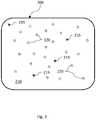
- FIG. 7illustrates an exemplary inflatable membrane after inversion, showing the pattern on the inner surface of the inflatable membrane, in accordance with certain aspects of the present disclosure
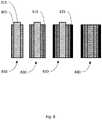
- FIG. 8is a diagram illustrating a second exemplary process of forming the inflatable membrane around the casting plate, in accordance with certain aspects of the present disclosure
- FIG. 9illustrates a process flow diagram for a representative method of making inflatable membrane material, in accordance with certain aspects of the present disclosure.
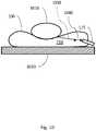
- FIG. 10illustrates a simplified diagram imaging the interior surface of the inflatable membrane through a media that differentially absorbs different wavelengths to determine the shape of an exterior surface of an object, in accordance with certain aspects of the present disclosure.
- an interior surface of an object or cavitymay be scanned by imaging a pattern of light emitted or reflected from the interior surface. Based on the contours or three-dimensional shape of the interior surface, the received pattern of light may be interpreted to reconstruct the shape of the interior surface.
- a deformable membranemay be applied to the interior surface to closely approximate the shape of the interior surface.
- the deformable membranemay include a particular pattern or other features that may facilitate reconstruction of the three-dimensional shape of the interior surface.
- the deformable membranemay be applied to, for example a cavity, by inflating the deformable membrane until the deformable membrane closely conforms to at least a portion of the interior surface of the cavity, such as an ear or other cavity.
- Other methods of applying the deformable membranemay be implemented, for example, spraying, pouring, pressing, molding, or the like, of the deformable membrane.
- the deformable membranewill be referred to as an inflatable membrane.
- FIG. 1is a diagram illustrating a simplified sectional view of an exemplary inflatable membrane 100 in accordance with certain aspects of the present disclosure.
- the inflatable membrane 100may fill a cavity 105 and closely conform to an inner surface 110 of the cavity.
- a light source 115may be introduced into the cavity 105 to illuminate, with incident light 120 , at least part of the inflatable membrane 100 .
- the inflatable membrane 100may include a fluorescing material which may generate fluoresced light 130 .
- the fluoresced light 130may be received by a detector (here shown integrated with the light source 115 ). When imaged through an optically tuned differentially absorbing medium, the received light can be analyzed to determine an interior shape of the inflatable membrane 100 and hence of the cavity 105 .
- FIG. 1also includes an expanded view of a portion of the inflatable membrane 100 .
- the expanded viewillustrates incident light 120 reaching the inflatable membrane 100 .
- the inflatable membrane 100may be constructed of three layers of material, though any number or combination of layers may be implemented.
- One layermay be a fluorescing layer 125 of florescent material may that lie behind a pattern layer 140 , although the pattern layer 125 may be located right behind the pattern layer 140 as well.
- the pattern layer 140may include the pattern used to reconstruct the shape of the cavity 105 . Because the pattern layer 140 may be between the fluorescing layer 125 and the detector, the fluoresced light 130 may be partially blocked by the material making the pattern.
- the material making the patternmay not fluoresce, creating a negative image corresponding to the pattern.
- the fluoresced light 130may include information about the pattern that may be analyzed to determine the shape of the cavity 105 .
- the pigmented layer 145may be applied to be between the fluorescing layer 125 and the cavity 105 .
- the inflatable membrane 100contains a fluorescent material, such as a dye or pigment, which may return an image of fluoresced light 130 when illuminated with, for example, visible blue or UV (ultra-violet) light.
- the concentration of pigmentmay be configured to be high enough to provide adequate opacification but low enough to provide a soft enough material to allow for adequate conformance of small features in the cavity.
- the inflatable membrane 100may contain a fluorescent dye that returns an image when illuminated with white light.
- Some implementationsmay include an inflatable membrane 100 that may contain a fluorescent dye that returns an image when illuminated with light that is not visible to the naked eye, that is to say light has a wavelength that is outside the range of about 390 to 700 nm.
- the membrane 100may fluoresce red and green light.
- the inflatable membrane 100may fluoresce in any combination of two or more wavelengths, or ranges of wavelengths, of light in response to illumination with blue or white light.
- the ratio of red to green fluoresced lightmay not vary by more than about 0.5% over the length of the membrane, more than 1.0%, or more than 2.0% over the length of the membrane.
- the inflatable membrane 100may be filled with a medium 150 to inflate the inflatable membrane 100 .
- the medium 150may, for example, be a liquid, a dissolved gas, a gel, a hydrogel, and/or any combination of the four.
- the medium 150may include additives dissolved into, or suspended in, the medium 150 to provide optical properties that may be used with imaging techniques to measure the shape of the interior surface of the inflatable membrane 100 . These properties may include, for example, selective absorption/attenuation where one or more wavelengths of light are absorbed more than one or more other wavelengths.
- medium 150may include a colored dye, suspension, a luminescent substance, and/or a fluorescent substance (and/or any other material having selective attenuation properties).
- the selective attenuation propertiesmay allow a detector to receive the selectively attenuated light to determine the shape of, distance to, and/or other properties of the scanned interior surface of inflatable membrane 100 .
- the medium 150may be a red fluid that preferentially absorbs the green light.
- the medium 150may also contain a bio-neutralizing, anti-microbial, or anti-oxidizing agent to improve the shelf life of the medium 150 as well as a buffering agent to improve the stability of the medium 150 .
- FIG. 2is a simplified diagram illustrating a composite material 200 having a matrix material 210 , a pigment material 215 , and a fluorescent material 220 , in accordance with certain aspects of the present disclosure.
- the inflatable membrane 100may include one or more layers of material. Some implementations may have different types of material comingled in a layer to form a composite layer.
- the inflatable membrane 100may include, for example, the matrix material 210 , the pigment material 215 for opacity, and the fluorescent material 220 , such as a pigment or dye.
- the pigment materialmay also affect the mechanical properties, such as the stiffness of the membrane may be configured by adjusting the amount of pigment material. All of the materials may be selected to be biocompatible and to illicit as little reaction from the human body as possible. In some example implementations, this may be considered important because a goal of using the inflatable membrane 100 with a 3D scanning system is to improve comfort for the patient during fabrication of a 3D rendering or model of an anatomical cavity.
- the matrix material 210may be a biocompatible or bio-inert polymer or mixture of polymers.
- the pigment material 215 for opacitymay have little cytotoxic, sensitization, and/or irritation activity at the particle sizes and exposure levels that are possible when using the inflatable membrane 100 .
- the inflatable membrane 100may comprise predominantly the matrix material 210 .
- the raw materials of the inflatable membrane 100may comprise predominantly the matrix material 210 or its precursors, as well.
- the matrix material 210may be combined as a liquid with the pigment material 215 for opacity and fluorescent dye during fabrication.
- Post-mixing curingwhich can include casting, molding, heating, or the addition of further chemicals, may cause the matrix material 210 to transition from a pourable material, to a solid material with sufficient elasticity and toughness, as described above, to be useful in the scenarios described herein, such as multiple inflations at multiple degrees of inflation (e.g., multiple degrees of pressurization of the inflatable membrane 100 ).
- the inflatable membrane 100may have a composite layer including a matrix material 210 with pigment material 215 for opacity and particles of fluorescent material 220 which are not distinguishable to the naked eye as discrete particles when in the inflatable membrane 100 .
- the inflatable membrane 100has the pigment material 215 and fluorescent material 220 embedded in the bulk of the matrix material 210 , on the surface of the inflatable membrane 100 , or some combination thereof.
- the pigment material 215may be embedded within the matrix material 210 and the fluorescent material 220 may be on the surface of the inflatable membrane 100
- the fluorescent material 220may be embedded in the matrix material 210 and the pigment material 215 may be on the surface of the inflatable membrane 100 .
- the matrix material 210may have both the pigment particles 215 and the fluorescent material 220 embedded in it and additional fluorescent material may be applied to the surface of the inflatable membrane 100 , such as fiducials or other markers.
- additional fluorescent materialmay be applied to the surface of the inflatable membrane 100 , such as fiducials or other markers.
- the material properties of the inflatable membrane 100may be attributable to the combination of the matrix material 210 , the pigment material 215 and the fluorescent material 220 .
- the matrix materialmay include one or more polymer.
- the matrix material 210may be a low-hardness (e.g., a low-durometer) liquid silicone rubber, a liquid silicone elastomer, or a combination thereof.
- Exemplary siliconesinclude silicones with the amount (e.g., mass) of silica used in production of the silicone reduced by a predetermined amount, such as 1%, 2%, 5%, 10%, 20%, and/or other amounts as well. In some implementations, more of one of the components of the matrix material 210 may be used to modify the cross-linking density of the matrix material 210 , reducing the silica concentration.
- the matrix material 210 of the inflatable membrane 100can also include silica enriched silicone, latex, polyurethane, polyisoprene, engineered thermoplastic polyurethane, thermoplastic polyethylene, plastisols, or any combination thereof.
- One or more thermoplastic elastomersmay also be included in the matrix material 210 .
- An example of a thermoplastic elastomeris MD-447, although other types of thermoplastic elastomers may be used as well.
- the pigment material 215may include any suitable particulates, including suitable metals, metal oxides, metal carbides, and carbon blacks.
- the pigment material 215may be a carbon black, such as a channel carbon black, a furnace carbon black, a lampblack, a thermal carbon black, an acetylene carbon black, or any combination thereof.
- the pigment material 215may include primary particles, aggregates of primary particles, and agglomerates of primary particles.
- the primary particlescan range in diameter from about 15 nm to about 20 nm.
- the aggregatescan range in diameter from about 50 nm to about 400 nm. Agglomerates of the primary particles can range in diameter from the size of aggregates up to 2 mm.
- the primary particle size of the pigment material 215can range from about 10 to 30 nm
- the size of aggregates of primary particles of pigment material 215can range from about 50 to 200 nm
- aggregates of pigment material 215may be up to 2 mm in diameter.
- High-purity furnace carbon blackcan have total polycyclic aromatic hydrocarbons (PAHs) at a level not exceeding about 0.5 parts per million (ppm) and benzo[a]pyrene not exceeding about 5.0 parts per billion (ppb).
- PAHstotal polycyclic aromatic hydrocarbons
- the fluorescent material 220 of the inflatable membrane 100may be of a single type of fluorescent dye or a combination of fluorescent dyes. Any fluorescent material 220 , such as dye or pigment, or combination of fluorescent material 220 with a large Stoke's shift and a broad emission spectrum with at least two bandwidths that are suitable to use as signal in the 3D scanning system can be used in the inflatable membrane 100 with the differentially absorbing medium 150 .
- the fluorescent material 220 of an inflatable membrane 100can be a fluorescent dye that has reduced or negligible reflectance at the wavelengths which a 3D scanning system uses as signal.
- the inflatable membrane 100may contain a concentration of fluorescent material 220 high enough to obtain good signal, but low enough for any reflection from the fluorescent material to be ignored.
- the ideal fluorescent material 220may be a dye that absorbs at higher energy wavelengths, such as blue or UV; a dye that fluoresces light that includes red and green wavelengths; and a dye that is used at a concentration such that the dye reflects little to no red or green light.
- a dyemay be considered transparent to the wavelengths of light selected by the system, or a user, as the signal wavelengths.
- a dye that is excited by blue light, fluoresces yellow light (that includes red and green light in its emission spectrum), and is transparent to red and green lightis an ideal, invisible fluorescent dye.
- the dyeis invisible in that it does not contribute substantially to the signal noise because it does not reflect, scatter, or otherwise perturb the fluoresced light at the wavelengths of interest, namely the red and green wavelengths.
- the dyemay be invisible also if it is used at a concentration where any reflectance or scattering is negligible at the wavelengths of interest.
- This fluorescent dyemay comprise a metal complex with a melting point of around 350-356° C., and may be excited by light with any light in a range from UV to blue, such as light with a wavelength of about 366 nm, and which has an emission spectra with a peak at a wavelength of 549 nm.
- the dyemay be a yellow powder when not mixed with a matrix material 215 and has a particle size distribution, based upon the particle diameter, ranging from about 2.0 microns to about 20 microns.
- the particles used in any of the materials hereinmay be rod shaped (e.g., high aspect ratio particles) with a diameter of about 2 microns and a length of about 20 microns.
- An invisible, or transparent, fluorescent dye used as the fluorescent material 220 in an inflatable membrane 100can be a metal complex, an organic molecule, or any other material with suitable excitation, emission (i.e., fluorescent), and reflective and scattering properties.
- FIG. 3is a diagram illustrating an exemplary process of forming the inflatable membrane 100 around a casting plate 310 , in accordance with certain aspects of the present disclosure.
- a transferrable materialmay be applied to an outer surface of a casting plate 310 to form a pattern on the outer surface of the casting plate 310 .
- the transferrable materialmay be transferred from the casting plate 310 to the inner surface of the inflatable membrane 100 .
- the transferring mechanismmay be similar to ink being transferred from one surface to another, a chemical bonding process such as an adhesion of some of the transferrable material to the inflatable membrane 100 , or the like.
- the transferrable materialmay include the pigment material 215 or any other type of dye, ink, or other material to form the pattern.
- the transferrable materialmay form a pattern on the inner surface of the inflatable membrane 100 .
- the round and/or spherical character of the transferrable material and the specific pattern shown in FIG. 3is merely an example or for illustrative purposes and not intended to be limiting.
- Other patternsmay include, for example, grids, circles, geometric patterns (hexagonal, octagonal, etc.), variations in color, variations in intensity, or other types of spatially varying patterns.
- the casting plate 310may include, for example, a mandrel or other object that the inflatable membrane 100 may be formed around.
- the casting plate 310(or mandrel) may have an outer shape that is generally elongate and may generally conform to a cavity corresponding to an interior of an ear.
- the degree of conformitycan vary between, for example, a conical shape (as shown in FIG. 4 , below), a cylindrical shape, or a shape that may generally conform to features of a typical person's inner ear.
- a composite material 350may be applied, at 320 , to the outer surface of the casting plate 310 , after the applying of the transferrable material, to form an inflatable membrane 100 .
- the composite material 350may cover at least a portion of the pattern and include the florescent material 220 , the pigment material 215 , or both. In other implementations, the composite material may include other materials.
- the inflatable membrane 100may be cured to allow removal of the inflatable membrane 100 from the casting plate 310 . Once removed, the inflatable membrane 100 may include an inner surface having the pattern. As discussed above, the pattern may be detectable upon receiving light that causes the fluorescing material 220 to emit fluoresced light 130 .
- FIG. 4illustrates applying a transferrable material to an outer surface of a casting plate 310 to form a pattern, in accordance with certain aspects of the present disclosure.
- the transferrable materialmay be applied by at least one of a hypodermic needle, painting with a brush, spraying, printing from a laser jet printer, printing from a pad printer, etching, and dipping.
- FIG. 4illustrates a hypodermic needle being used for this process.
- FIG. 5illustrates applying a composite material 350 to the outer surface of the casting plate 310 after the applying of the transferrable material, in accordance with certain aspects of the present disclosure.
- the composite material 350may be applied by dipping the casting plate 310 with the transferrable material into the composite material 350 .
- Any of the composite material 350 , matrix material 210 , pigment material 215 , and fluorescent material 220may be contained in a dipping container or other material dispenser.
- the windowmay be an aperture or may be another material, for example transparent plastic, that allows the transmission of light through a distal end of the inflatable membrane 100 .
- the distal endmay be the end of the inflatable membrane that is inserted furthest into the ear of a person.
- the window, or an aperture configured to accept a windowmay be formed by not fully dipping or coating the casting plate 310 with the composite material 350 . In this way, the aperture can be formed by selectively applying any of the layers to the outer surface of the casting plate 310 , without applying any of the layers to the distal end of the casting plate.
- the windowmay be formed by removing material, for example by cutting, from the end of a fully coated casting plate 310 (as shown in FIG. 6 ).
- a transparent materialfor example plastic or glass, can be applied to the distal end of the inflatable membrane 100 to span the aperture and form the window.
- a userWhen inserting the inflatable membrane into a cavity (for example in an ear or other type of cavity), a user can insert the inflatable membrane 100 using the window as a guide to avoid unwanted contact with interior structures or surfaces in the cavity.
- a detector(which may be the same as the detector used to detect reflected or fluoresced light) can image the interior of the conforming membrane through the window while the inflatable membrane 100 is being inserted or otherwise used. In some implementations, the imaging may occur through the absorbing medium including inside the inflatable membrane.
- FIG. 6illustrates forming of the inflatable membrane 100 after removal from the composite material 350 , in accordance with certain aspects of the present disclosure.
- the inflatable membrane 100may be cured, for example by drying in air, with heat, with cooling, or the like. Once cured, the inflatable membrane 100 may be removed from the casting plate 310 .
- FIG. 7illustrates an exemplary inflatable membrane 100 after inversion, showing the pattern on the inner surface of the inflatable membrane 100 , in accordance with certain aspects of the present disclosure.
- the transferrable material(which is shown not fluorescing) may provide a measurable contrast that can be imaged by the detector.
- the imagesmay be analyzed by an image analysis program to determine the interior shape of the cavity 105 .
- FIG. 8is a diagram illustrating a second exemplary process of forming the inflatable membrane 100 around a casting plate 310 , in accordance with certain aspects of the present disclosure.
- a first layer 805 of a fiducial materialmay be applied to an outer surface of a casting plate 310 .
- the fiducial materialmay include fiducial markers suspended in the fiducial material. Fiducial markers may be similar to the transferrable material in that because of the way they block light from the fluorescent material, the fiducial markers themselves may form a random pattern that can be imaged.
- the fiducial markerscan include, for example, grains, shards, fragments, or other small objects (e.g., 50-400 microns, although other size may be used as well).
- the fiducial marker particle sizeif the fiducial marker particle size is below 50 microns, the markers may be too small to be resolved by some imaging systems and/or may not provide sufficient contrast for the imaging system to identify a pattern. And, if the fiducial marker particle size is above 400 microns, the markers may be too large and thus obscure the fluorescent signal behind the fiducial layer.
- Features of the suspended fiducial materialmay be interpreted as a random pattern by the detector. For example, the density, orientation, appearance, or the like, can define a random pattern.
- a fiducial material having fiducial markers at a uniform density throughout the fiducial materialcan conform to an unperturbed state of the inflatable membrane 100 .
- the local area density of the fiducial markersmay decrease, indicating a deformation of the inflatable membrane 100 .
- Similar changes to the random patterncan indicate compression or a particular local surface orientation of the inflatable membrane 100 .
- the inflatable membrane 100can also include, at any of the layers described herein or formed by the fiducial material, a texture that can be imaged (via differential absorption as noted) to enable the identification of the shape of the inner surface of the inflatable membrane 100 .
- the patternmay be used to enable combing, or stitching, adjacent surface patches of imaging.
- the texturecan include, for example, groves, etched channels, or grooves filled with another material of a different color, fluorescent property, surface texture, or the like.
- the texturecan be formed as a random pattern, a grid, a grid of varying shape, or the like to provide a surface with reference points that can be imaged by a detector to determine the contours or shape of the interior or exterior surface of the inflatable membrane 100 .
- a second layer 815 of a composite material 350may be applied to the first layer to form an inflatable membrane 100 .
- the composite material 350may include a florescent material 220 and a pigment material 215 .
- a third layer 825may be applied to the second layer 815 .
- the third layer 825may include the pigment material 215 and not include the fluorescent material 220 .
- the third layer 825includes only the pigment material 220 .
- the inflatable membrane 100may be cured to allow removal of the inflatable membrane 100 from the casting plate 310 .
- the inflatable membrane 100may include an inner surface having the fiducial markers detectable upon receiving of light causing the fluorescing material to emit florescent light.
- the first layer 805 , the second layer 815 , or the third layer 825may be applied by dipping the casting plate 310 into the fiducial material, the composite material, or the pigment material.
- the combining and processing of the raw materials of the inflatable membrane 100may correlate strongly to the physical and optical properties of the finished inflatable membrane 100 used in a 3D scanning system. Fabrication methods that can be used to make inflatable membranes are described below. Variation of the ratio of the constituent materials of the inflatable membrane 100 may cause variation in the performance of the inflatable membrane 100 , and such variations in raw materials will be described first. Then, various ways of mixing the raw materials will be described.
- the raw materials for fabricating an inflatable membrane 100can include the matrix material 210 , the pigment material 215 , and the fluorescent material, as described above.
- the raw materialscan be combined by weight in the following ratios, in which the first number in the ratio is the weight of the raw material (e.g., pigment material 215 or fluorescent material 220 ) and the second number is the weight of the matrix material 210 in the mixture.
- an inflatable membrane 100can include about 1:400 by weight of pigment material 215 for opacity and about 1:50 by weight of fluorescent material 220 .
- an inflatable membrane 100may include pigment material 215 by weight in an amount ranging from about 1:350 to about 1:450 and fluorescent material 220 by weight in an amount ranging from about 1:100 to about 1:25.
- a mixture called a masterbatchthat is used to fabricate an inflatable membrane 100 , can be created.
- the masterbatch mixturecan be a small volume of material, such as about 10 g, that includes, for example, about 0.09 ⁇ 0.01 g of pigment material 215 , about 0.73 ⁇ 0.01 g of fluorescent dye, and about 9.17 ⁇ 0.02 g of matrix material.
- the masterbatch mixturecan be a larger volume of material, such as about 240 g, that includes about 0.6 ⁇ 0.01 of pigment material 215 , about 4.8 ⁇ 0.01 g fluorescent dye, and about 120.0 ⁇ 0.02 g matrix material 210 .
- the concentrationif the concentration is too low, the intensity may not be bright enough to successfully image at a distance and make meaningful measurements. But if the concentration is too high, there may be reflections which can confound the measurements inside the membrane. With respect to the pigment material, if the concentration is too low, the membrane may not be opaque enough and ambient light from outside the membrane may introduce error into the measurements (which may reduce the overall signal to noise ratio). If however the concentration is too high, the material may be too stiff and may not conform to small features on the inner surface of the cavity (which may introduce error into the overall geometry computed by the scanning system).
- the matrix material 210may be a two-part elastomer or polymer, and only one part may be added to the masterbatch. In other implementations, the matrix material 210 may not have more than one portion, and part of the mass of the matrix material 210 may be added to the masterbatch, and the rest of the matrix material 210 may be combined with the masterbatch following some processing.
- Fabricating the masterbatch mixturecan include some processing of the combined matrix material 210 . Such processing may include mixing in speed mixer, milling in an attrition mill, ball milling, using media while milling, mixing, or centrifuging the mixture.
- the mediamay be ball milling media, such as ceramic or metal media. Ceramic media can include yttria stabilized zirconia pellets or balls, silica balls, alumina pellets or balls, or the like.
- Metal mediacan include stainless steel balls, aluminum balls, or metal balls of any metal or alloy that is corrosion resistant and wear resistant in the presence of the matrix material, pigment, and fluorescent material. Fabricating the masterbatch can also include allowing the mixture to rest, or reduce in temperature, after mixing to an elevated temperature.
- the rest timecan vary, and can include a time of at least about 30 seconds, at least about 60 seconds, at least about 90 seconds, and at least about 120 seconds.
- the masterbatch mixturecan be scraped down from the sides of the mixing container, as well as returning to ambient or near ambient temperature.
- a centrifuge set to various speeds of mixingcan be used, with speeds ranging from about 1500 revolutions per minute (RPM) to about 3000 RPM, including from about 2000 RPM to about 2500 RPM.
- RPMrevolutions per minute
- various sizes of milling or mixing mediacan be used, of the material and shape described above, and the number of media can also be varied.
- the mixturemay be cured, molded, or dip-coated into sheets or other suitable shapes for the inflatable membrane 100 .
- Curing the inflatable membrane 100can include casting the membrane onto metal sheets, such as aluminum sheets, heating the cast material, or simply aging the material, such as by allowing it to sit, for an extended period of time.
- solventsmay be used dissolve the raw materials into solution.
- the amount and type of solventmay affect the viscosity of the solution.
- the viscosity of the solution coupled with the speed of insertion and removal from the dipping bathmay determine the thickness of the dipped layer.
- the solventmay evaporate as the material cures.
- FIG. 9illustrates a process flow diagram for a representative method of making inflatable membrane material, in accordance with certain aspects of the present disclosure.
- the first layer of material applied to the outer surface of the casting plateis a transferable layer.
- the transferable layercan be discrete, discontinuous or contiguous across the entire castable region of the outer surface of the casting plate.
- the transferable layermay be a single region or marker that covers only a region of the outer surface of the casting plate.
- the transferable layermay be discontinuous so that it forms a pattern of some kind with multiple discrete points where the pattern covers some portion of the casting surface.
- the transferable layermay be contiguous so that it spans the entire castable area of the casting plate with no voids or gaps in coverage.
- the first stepmay be to carefully weigh out predetermined amounts of the matrix material 210 , pigment material 215 , and fluorescent material 220 into a mixing container, as in 910 .
- the material weighed outtypically is for the creation of a masterbatch mixture, and it is mixed accordingly, 920 .
- the mixing protocol for creating a masterbatchcan include using a centrifuge, such as a dual asymmetric centrifuge, to initially spin the material in the mixing container for a predetermined time at a predetermined speed, such as for about 60 seconds at 2500 revolutions per minute (RPM).
- a centrifugesuch as a dual asymmetric centrifuge
- the protocolmay then specify for the scraping of the material down from the sides of the mixing container and to add mixing or milling media, such as about ten ceramic cylinders (e.g., 10 millimeter cylinders), and then to spin the material in the mixing container for a predetermined time at a predetermined speed, such as for about 60 seconds at about 2100 RPM.
- mixing or milling mediasuch as about ten ceramic cylinders (e.g., 10 millimeter cylinders)
- the masterbatch mixturemay be allowed to rest, or cool, for a predetermined amount of time, such as two minutes.
- the sides of the mixing containermay be scraped down before repeating of the spinning of the mixing container.
- the resting, scraping, and spinningmay be repeated a set number of times for each process or until achieving a desired consistency.
- the protocol to produce a masterbatch mixturemay be repeated to create a desired volume or mass of material for any number of inflatable membranes 100 .
- more matrix materialmay be mixed with the masterbatch mixture to arrive at the final ratio of the constituent materials, 930 .
- Thismay be about a 1:1 mixture of the masterbatch mixture and pure matrix material, or it can be a different ratio of masterbatch mixture to pure matrix material.
- the matrix materialmay have two components, one of which may be mixed with the masterbatch mixture, while the other component may be mixed in later to arrive at the final ratios of the constituents.
- the masterbatch and pure matrix material 210 , or masterbatch and second component of the matrix material 210may not be mixed until right before the membrane is ready to be formed.
- the masterbatch and matrix materialmay be mixed using a mixing apparatus, such as centrifuge, as well as mixing or milling media to create a mixture that eventually becomes the inflatable membrane 100 material, as in box 930 .
- casting plates 310may be used to form and cure the inflatable membrane 100 .
- the casting plates 310may be prepared, as in box 940 .
- the casting plates 310may be ceramic, metal, polymer or any suitable combination thereof, and preparation may include cleaning the plates with soap and water, with organic solvents, with mild acid, or a combination thereof.
- the casting plates 310may be treated with a surface treatment, such as applying a mold release agent or other surface treatment to facilitate removal of the inflatable membrane from the casting plate 310 .
- a transferrable materialmay be applied to an outer surface of a casting plate 310 to form a pattern on the outer surface of the casting plate 310 .
- a composite materialmay be applied to the outer surface of the casting plate 310 to form an inflatable membrane 100 .
- the composite materialmay cover at least a portion of the pattern and comprising a florescent material and a pigment material.
- the inflatable membranemay be cured to allow removal of the inflatable membrane 100 from the casting plate 310 .
- the inflatable membrane 100may include an inner surface having the pattern detectable upon receiving of light causing the fluorescing material to emit florescent light.
- the casting plates 310may be attached to an apparatus that allows for the simultaneous application of the casting plates 310 and conveyance of the spreadable membrane material along a path. Such conveyance can also include the application of heat or other modifications to the environment, such as relative humidity, by a membrane curing or fabricating facility or system. The application of heat or adjustment of the environment may facilitate curing of the inflatable membrane 100 .
- the cured membrane materialmay be removed from the casting plates 310 , and the membrane material may be stored or sent to another facility for further processing. Further processing may include the application of more fluorescent material to create fiducial markings, cutting and joining the membrane material to create an inflatable membrane 100 sized appropriately for an intended use, assembly into a system, and the like.
- Any of the features described herein, for example the process described above with regard to FIG. 9may be performed under the control of, or assisted by, one or more computer processors.
- FIG. 10illustrates a simplified diagram imaging the interior surface of the inflatable membrane 100 through a media that differentially absorbs different wavelengths to determine the shape of an exterior surface of an object 1010 , in accordance with certain aspects of the present disclosure.
- the inflatable membrane 100 described hereincan be used to also determine the surface shape or features of an object 1010 that is not a cavity.
- an objectcan be placed or otherwise brought into contact with the inflatable membrane 100 , optionally resting on a surface 1020 . This can cause the inflatable membrane 100 to conform to an exterior surface of the object, as opposed to an interior surface of a cavity.
- the light source 115(which may also include a detector) may image reflected or fluoresced light from the interior surface of the inflatable membrane 100 .
- the distorted surface of the inflatable membranecan then be analyzed to determine the exterior shape of the object 1010 .
- the inflatable membrane 100can include a medium 150 that differentially attenuates light (from a light source 115 or from a fluorescent portion of the inflatable membrane 100 ). As the light attenuates there may be a first intensity of light 1030 that is strongly attenuated and a second intensity of light 1040 that is attenuated less than the first intensity of light 1030 . The measured intensities may be compared to determine the shape of the interior surface of the inflatable membrane 115 and hence the shape of the exterior surface of the object 1010 .
- Applications of this implementationcan include measuring the surface features of the external ear features or other facial features, a hand pressing on the inflatable membrane 100 , a foot standing on the inflatable membrane 100 , or the like.
- the object 1010can also include any sort inanimate object that is positioned to deform the inflatable membrane 100 as described herein.
- the inflatable membrane 100can be filled with a fluid to provide a desired pressure or to facilitate transmission of light to the detector for imaging.
- the external surface being scannedcould exist in an environment where a vacuum or otherwise reduced pressure could be applied to create an increased pressure differential across the surface of the inflatable membrane 100 improving conformance of the inflatable membrane 100 to the higher resolution features on the surface being inspected or analyzed.
- one or more aspects or features of the subject matter described hereincan be implemented on a computer having a display device, such as for example a cathode ray tube (CRT) or a liquid crystal display (LCD) or a light emitting diode (LED) monitor for displaying information to the user and a keyboard and a pointing device, such as for example a mouse or a trackball, by which the user may provide input to the computer.
- a display devicesuch as for example a cathode ray tube (CRT) or a liquid crystal display (LCD) or a light emitting diode (LED) monitor for displaying information to the user
- a keyboard and a pointing devicesuch as for example a mouse or a trackball
- feedback provided to the usercan be any form of sensory feedback, such as for example visual feedback, auditory feedback, or tactile feedback; and input from the user may be received in any form, including, but not limited to, acoustic, speech, or tactile input.
- Other possible input devicesinclude, but are not limited to, touch screens or other touch-sensitive devices such as single or multi-point resistive or capacitive trackpads, voice recognition hardware and software, optical scanners, optical pointers, digital image capture devices and associated interpretation software, and the like.
- phrases such as “at least one of” or “one or more of”may occur followed by a conjunctive list of elements or features.
- the term “and/or”may also occur in a list of two or more elements or features. Unless otherwise implicitly or explicitly contradicted by the context in which it used, such a phrase is intended to mean any of the listed elements or features individually or any of the recited elements or features in combination with any of the other recited elements or features.
- the phrases “at least one of A and B;” “one or more of A and B;” and “A and/or B”are each intended to mean “A alone, B alone, or A and B together.”
- a similar interpretationis also intended for lists including three or more items.
- the phrases “at least one of A, B, and C;” “one or more of A, B, and C;” and “A, B, and/or C”are each intended to mean “A alone, B alone, C alone, A and B together, A and C together, B and C together, or A and B and C together.”
- Use of the term “based on,” above and in the claimsis intended to mean, “based at least in part on,” such that an unrecited feature or element is also permissible.
Landscapes
- Engineering & Computer Science (AREA)
- Mechanical Engineering (AREA)
- Investigating, Analyzing Materials By Fluorescence Or Luminescence (AREA)
- Length Measuring Devices By Optical Means (AREA)
Abstract
Description
Claims (16)
Priority Applications (1)
| Application Number | Priority Date | Filing Date | Title |
|---|---|---|---|
| US17/520,406US11559925B2 (en) | 2016-12-19 | 2021-11-05 | Patterned inflatable membrane |
Applications Claiming Priority (4)
| Application Number | Priority Date | Filing Date | Title |
|---|---|---|---|
| US201662436340P | 2016-12-19 | 2016-12-19 | |
| US15/845,172US11203134B2 (en) | 2016-12-19 | 2017-12-18 | Manufacture of inflatable membranes |
| US16/032,614US11203135B2 (en) | 2016-12-19 | 2018-07-11 | Manufacture of inflatable membranes |
| US17/520,406US11559925B2 (en) | 2016-12-19 | 2021-11-05 | Patterned inflatable membrane |
Related Parent Applications (1)
| Application Number | Title | Priority Date | Filing Date |
|---|---|---|---|
| US16/032,614DivisionUS11203135B2 (en) | 2016-12-19 | 2018-07-11 | Manufacture of inflatable membranes |
Publications (2)
| Publication Number | Publication Date |
|---|---|
| US20220055259A1 US20220055259A1 (en) | 2022-02-24 |
| US11559925B2true US11559925B2 (en) | 2023-01-24 |
Family
ID=62625307
Family Applications (4)
| Application Number | Title | Priority Date | Filing Date |
|---|---|---|---|
| US15/845,172Active2038-04-06US11203134B2 (en) | 2016-12-19 | 2017-12-18 | Manufacture of inflatable membranes |
| US16/032,614Active2039-02-15US11203135B2 (en) | 2016-12-19 | 2018-07-11 | Manufacture of inflatable membranes |
| US17/520,406ActiveUS11559925B2 (en) | 2016-12-19 | 2021-11-05 | Patterned inflatable membrane |
| US17/520,401ActiveUS11584046B2 (en) | 2016-12-19 | 2021-11-05 | Patterned inflatable membranes |
Family Applications Before (2)
| Application Number | Title | Priority Date | Filing Date |
|---|---|---|---|
| US15/845,172Active2038-04-06US11203134B2 (en) | 2016-12-19 | 2017-12-18 | Manufacture of inflatable membranes |
| US16/032,614Active2039-02-15US11203135B2 (en) | 2016-12-19 | 2018-07-11 | Manufacture of inflatable membranes |
Family Applications After (1)
| Application Number | Title | Priority Date | Filing Date |
|---|---|---|---|
| US17/520,401ActiveUS11584046B2 (en) | 2016-12-19 | 2021-11-05 | Patterned inflatable membranes |
Country Status (4)
| Country | Link |
|---|---|
| US (4) | US11203134B2 (en) |
| EP (1) | EP3554349A4 (en) |
| CA (1) | CA3040177A1 (en) |
| WO (1) | WO2018118772A1 (en) |
Cited By (1)
| Publication number | Priority date | Publication date | Assignee | Title |
|---|---|---|---|---|
| US20210401290A1 (en)* | 2013-03-15 | 2021-12-30 | Lantos Technologies, Inc. | Systems and methods for verifying the opacity of an inflatable membrane |
Families Citing this family (5)
| Publication number | Priority date | Publication date | Assignee | Title |
|---|---|---|---|---|
| US20120232652A1 (en)* | 2011-03-07 | 2012-09-13 | Rolando Mora | Implant with a visual indicator of a barrier layer |
| US10869597B2 (en) | 2014-11-25 | 2020-12-22 | Lantos Technologies, Inc. | Air removal and fluid transfer from a closed system |
| CN108476352A (en) | 2015-10-09 | 2018-08-31 | 兰托斯科技公司 | Custom Earbud Scanning and Manufacturing |
| CA3040177A1 (en) | 2016-12-19 | 2018-06-28 | Robert J. Fei | Manufacture of inflatable membranes |
| US12304088B2 (en) | 2021-05-06 | 2025-05-20 | Toyota Research Institute, Inc. | Systems and methods for calibrating deformable sensors |
Citations (115)
| Publication number | Priority date | Publication date | Assignee | Title |
|---|---|---|---|---|
| US3790653A (en) | 1971-12-29 | 1974-02-05 | Eastman Kodak Co | Polyester film base having uniform high optical density |
| US4643733A (en) | 1983-04-04 | 1987-02-17 | Hilton Becker | Permanent reconstruction implant and method of performing human tissue expansion |
| US5100587A (en) | 1989-11-13 | 1992-03-31 | The United States Of America As Represented By The Department Of Energy | Solid-state radioluminescent zeolite-containing composition and light sources |
| US5504316A (en) | 1990-05-08 | 1996-04-02 | Symbol Technologies, Inc. | Laser scanning system and scanning method for reading 1-D and 2-D barcode symbols |
| JPH08243262A (en) | 1995-03-09 | 1996-09-24 | Hideki Kanai | Balloon |
| US5829350A (en)* | 1996-06-10 | 1998-11-03 | Sony Corporation | Printing apparatus and method for printing the inner surface of a cylindrical object |
| US6001059A (en) | 1998-05-18 | 1999-12-14 | Elliott; Peter Christopher | Otoscope retrofit to allow multipurpose use |
| US6254555B1 (en) | 1996-08-12 | 2001-07-03 | Primary Care Delivery Corporation | Instrument for diagnosing and treating soft tissue abnormalities through augmented soft tissue mobilization |
| US20020196954A1 (en) | 2001-06-22 | 2002-12-26 | Marxen Christopher J. | Modeling and fabrication of three-dimensional irregular surfaces for hearing instruments |
| US20030164952A1 (en) | 2000-08-25 | 2003-09-04 | Nikolaj Deichmann | Method and apparatus for three-dimensional optical scanning of interior surfaces |
| US20040107080A1 (en) | 2001-03-02 | 2004-06-03 | Nikolaj Deichmann | Method for modelling customised earpieces |
| US20050191451A1 (en) | 2004-02-27 | 2005-09-01 | Osika Louis S. | Container having fluorescent indicia |
| US20070106012A1 (en) | 2005-02-11 | 2007-05-10 | Krzysztof Matyjaszewski | Modified carbon particles |
| US20080027358A1 (en) | 2004-06-30 | 2008-01-31 | Ditens A/S | Morphometry of a Bodily Hollow System |
| US20080058629A1 (en) | 2006-08-21 | 2008-03-06 | University Of Washington | Optical fiber scope with both non-resonant illumination and resonant collection/imaging for multiple modes of operation |
| US20080234532A1 (en) | 2005-10-22 | 2008-09-25 | Invibio Limited | Fiducial marker |
| US20090171196A1 (en) | 2007-12-31 | 2009-07-02 | Olson Eric S | Method and apparatus for encoding interventional devices |
| US20090245530A1 (en) | 2008-02-20 | 2009-10-01 | Personics Holdings Inc. | Method and Device for Acoustic Sealing |
| US20090289938A1 (en) | 2008-05-20 | 2009-11-26 | Oticon A/S | Apparatus and method for representing a scanned surface |
| US20090296980A1 (en) | 2008-06-02 | 2009-12-03 | Steven Yi | System and Method for Producing a Geometric Model of the Auditory Canal |
| US20100019170A1 (en) | 2008-07-24 | 2010-01-28 | Hart Douglas P | Three-dimensional imaging using a fluorescent medium |
| US20100168562A1 (en) | 2008-12-31 | 2010-07-01 | Intuitive Surgical, Inc. | Fiducial marker design and detection for locating surgical instrument in images |
| US20100296664A1 (en) | 2009-02-23 | 2010-11-25 | Verto Medical Solutions Llc | Earpiece system |
| US20110009702A1 (en) | 2009-03-24 | 2011-01-13 | Olympus Corporation | Fluorescence observation apparatus |
| US20110076608A1 (en) | 2009-09-28 | 2011-03-31 | Evonik Degussa Gmbh | Carbon black, a process for preparation thereof and use thereof |
| US20110144480A1 (en) | 2009-12-10 | 2011-06-16 | Siemens Corporation | Stent marker detection using a learning based classifier in medical imaging |
| CN102177733A (en) | 2008-10-10 | 2011-09-07 | 唯听助听器公司 | Method for manufacturing a hearing aid having a custom fitted resilient component |
| US20110235843A1 (en) | 2009-02-13 | 2011-09-29 | Personics Holdings Inc. | Method and device for acoustic sealing and occlusion effect mitigation |
| US8047207B2 (en) | 2007-08-22 | 2011-11-01 | Personics Holdings Inc. | Orifice insertion devices and methods |
| US20110290005A1 (en) | 2008-07-24 | 2011-12-01 | Hart Douglas P | Dynamic three-dimensional imaging of ear canals |
| US20120065756A1 (en) | 2006-10-16 | 2012-03-15 | Ruedger Rubbert | Methods of Designing and Manufacturing Customized Dental Prosthesis for Periodontal or Osseointegration and Related Systems |
| US20120197093A1 (en) | 2011-01-27 | 2012-08-02 | Leboeuf Steven Francis | Apparatus and methods for monitoring physiological data during environmental interference |
| WO2012115863A2 (en) | 2011-02-22 | 2012-08-30 | 3M Innovative Properties Company | Hybrid stitching |
| US20120327426A1 (en) | 2008-07-24 | 2012-12-27 | Hart Douglas P | Inflatable membrane having non-uniform inflation characteristic |
| CA2840602A1 (en) | 2011-06-27 | 2013-01-03 | Massachusetts Institute Of Technology | Inflatable membrane for use in three-dimensional imaging |
| US20130002824A1 (en)* | 2008-07-24 | 2013-01-03 | Hart Douglas P | Integrated otoscope and three dimensional scanning system |
| US20130002426A1 (en) | 2008-07-24 | 2013-01-03 | Hart Douglas P | Enhanced sensors in three dimensional scanning system |
| US20130027516A1 (en)* | 2011-07-28 | 2013-01-31 | Hart Douglas P | Camera configuration for three-dimensional imaging of interior spaces |
| US20130078555A1 (en) | 2011-09-28 | 2013-03-28 | Hoya Corporation | Mask blank glass substrate, multilayer reflective film coated substrate, mask blank, mask, and methods of manufacturing the same |
| US20130158694A1 (en) | 2011-03-18 | 2013-06-20 | Natural Dental Implants Ag | Integrated Support Device For Providing Temporary Primary Stability to Dental Implants and Prosthesis, and Related Methods |
| US20130261655A1 (en) | 2012-02-13 | 2013-10-03 | Intervalve, Inc. | Ellipticity Measuring Device |
| CN103974183A (en) | 2014-05-26 | 2014-08-06 | 俞辰 | Customized earphone based on 3D (three-dimensional) printing technology and manufacturing method thereof |
| US20140272221A1 (en)* | 2013-03-15 | 2014-09-18 | Lantos Technologies, Inc. | Inflatable membrane for fluorescent imaging and improvements in dye materials |
| US20140277664A1 (en) | 2013-03-15 | 2014-09-18 | Fathom, Inc. | 3d printing systems and methods for fabricating injection molds |
| US20140275974A1 (en) | 2013-03-15 | 2014-09-18 | Mark Alan Samuels | Surgical Navigation Systems and Methods |
| US8840566B2 (en) | 2007-04-02 | 2014-09-23 | University Of Washington | Catheter with imaging capability acts as guidewire for cannula tools |
| US20140330133A1 (en) | 2013-05-02 | 2014-11-06 | VS Medtech, Inc. | Systems and methods for measuring and characterizing interior surfaces of luminal structures |
| US20150017779A1 (en) | 2011-02-15 | 2015-01-15 | SK Hynix Inc. | Semiconductor device having stacked storage nodes of capacitors in cell region separated from peripheral region |
| CN104333826A (en) | 2014-10-20 | 2015-02-04 | 广东佳禾声学科技有限公司 | Novel Bluetooth headset device and manufacturing method thereof |
| US20150036146A1 (en) | 2013-07-31 | 2015-02-05 | Corning Incorporated | Oct probes and oct optical probe component for use therein |
| WO2015017779A1 (en) | 2013-08-02 | 2015-02-05 | United Sciences, Llc. | Method of designing custom device for alleviating temporomandibular joint-related symptoms |
| US20150072377A1 (en) | 2012-04-16 | 2015-03-12 | Rapid Micro Biosystems, Inc. | Cell culturing device |
| CN104796806A (en) | 2014-01-16 | 2015-07-22 | 英塔玛·乔巴尼 | System and method for producing personalized earphones |
| CN104936054A (en) | 2015-04-28 | 2015-09-23 | 西安慕声电子科技有限公司 | Modularized profiling earphone and manufacturing method |
| US9291565B2 (en) | 2008-07-24 | 2016-03-22 | Massachusetts Institute Of Technology | Three dimensional scanning using membrane with optical features |
| WO2016086005A1 (en) | 2014-11-25 | 2016-06-02 | Lantos Technologies Inc. | Air removal and fluid transfer from a closed system |
| US20160171765A1 (en) | 2014-12-10 | 2016-06-16 | Dassault Systemes | Texturing a 3d modeled object |
| US20160224693A1 (en) | 2015-02-02 | 2016-08-04 | Dassault Systemes | Engraving a 2d image on a subdivision surface |
| US20160224690A1 (en) | 2015-01-30 | 2016-08-04 | Dentsply International, Inc. | System and Method for Adding Surface Detail to Digital Crown Models Created Using Statistical Techniques |
| US20160302011A1 (en) | 2010-12-20 | 2016-10-13 | Earlens Corporation | Anatomically customized ear canal hearing apparatus |
| US20170057169A1 (en) | 2015-08-24 | 2017-03-02 | Siemens Healthcare Gmbh | Personalized creation from medical imaging |
| WO2017062868A1 (en) | 2015-10-09 | 2017-04-13 | Lantos Technologies Inc. | Custom earbud scanning and fabrication |
| US20170127199A1 (en) | 2015-10-29 | 2017-05-04 | Starkey Laboratories, Inc. | Hearing assistance device and method of forming same |
| US20170160726A1 (en) | 2015-12-07 | 2017-06-08 | Dassault Systemes | Detecting cut-outs |
| US20170178400A1 (en) | 2015-12-22 | 2017-06-22 | Dassault Systemes | Hybrid streaming |
| US20170193699A1 (en) | 2015-12-31 | 2017-07-06 | Dassault Systemes | Reconstructing A 3D Modeled Object |
| US20170220730A1 (en) | 2016-02-02 | 2017-08-03 | Dassault Systemes | B-rep design with face trajectories |
| US20170359659A1 (en) | 2016-06-09 | 2017-12-14 | Alex VON BRASCH | Advanced scene classification for prosthesis |
| US20180110593A1 (en) | 2016-10-21 | 2018-04-26 | Wael Khalil | Customized porous supracrestal implant and materials and methods forming them |
| US20180178419A1 (en) | 2016-12-19 | 2018-06-28 | Lantos Technologies Inc. | Manufacture of inflatable membranes |
| US20180181682A1 (en) | 2016-12-22 | 2018-06-28 | Dassault Systemes | Replica selection |
| US20180271409A1 (en) | 2017-01-20 | 2018-09-27 | Figur8, Inc. | Body part motion analysis with wearable sensors |
| US20180307207A1 (en) | 2017-04-24 | 2018-10-25 | Autodesk, Inc. | Closed-loop robotic deposition of material |
| US20180338806A1 (en) | 2017-05-24 | 2018-11-29 | KindHeart, Inc. | Surgical simulation system using force sensing and optical tracking and robotic surgery system |
| US20190007762A1 (en) | 2017-06-30 | 2019-01-03 | Bose Corporation | Customized Ear Tips |
| US20190021865A1 (en) | 2016-02-17 | 2019-01-24 | Koninklijke Philips N.V. | Physical 3d anatomical structure model fabrication |
| US20190021880A1 (en) | 2016-01-13 | 2019-01-24 | Massachusetts Institute Of Technology | Method And System For Designing A Biomechanical Interface Contacting A Biological Body Segment |
| US20190096120A1 (en) | 2017-09-26 | 2019-03-28 | Dassault Systemes | Generating a 2d drawing representing a mechanical part |
| US20190213442A1 (en) | 2018-01-10 | 2019-07-11 | Siemens Healthcare Gmbh | Method and system for learning to obtain medical scans of patients |
| US20190282344A1 (en) | 2018-03-19 | 2019-09-19 | James R. Glidewell Dental Ceramics, Inc. | Dental cad automation using deep learning |
| US20190340013A1 (en) | 2018-05-06 | 2019-11-07 | Strong Force TX Portfolio 2018, LLC | Transaction-enabled systems and methods for providing provable access to executable algorithmic logic in a distributed ledger |
| US20200004224A1 (en) | 2018-06-27 | 2020-01-02 | Orthopedix, Inc. | Medical and surgical procedure training system |
| US20200051274A1 (en) | 2018-08-10 | 2020-02-13 | Holo Surgical Inc. | Computer assisted identification of appropriate anatomical structure for medical device placement during a surgical procedure |
| US20200066391A1 (en) | 2018-08-24 | 2020-02-27 | Rohit C. Sachdeva | Patient -centered system and methods for total orthodontic care management |
| US20200100871A1 (en) | 2018-09-27 | 2020-04-02 | Align Technology, Inc. | Aligner damage prediction and mitigation |
| US20200134245A1 (en) | 2018-10-26 | 2020-04-30 | Dassault Systemes | 3d design of b-rep skin |
| US20200159878A1 (en) | 2018-11-16 | 2020-05-21 | Starkey Laboratories, Inc. | Ear-wearable device shell modeling |
| US20200210631A1 (en) | 2018-12-26 | 2020-07-02 | Dassault Systemes | Designing a mechanical part |
| US20200210632A1 (en) | 2018-12-30 | 2020-07-02 | Dassault Systemes | Modeling using a weak type definition |
| US20200211276A1 (en) | 2018-12-29 | 2020-07-02 | Dassault Systemes | Learning a neural network for inference of editable feature trees |
| US20200252730A1 (en) | 2017-10-05 | 2020-08-06 | Cochlear Limited | Distraction remediation at a hearing prosthesis |
| US20200261231A1 (en) | 2019-02-19 | 2020-08-20 | The Chinese University Of Hong Kong | Semi-automated imaging reconstruction for orbital fracture repair |
| US20200268260A1 (en) | 2019-02-26 | 2020-08-27 | Bao Tran | Hearing and monitoring system |
| US20200275976A1 (en) | 2019-02-05 | 2020-09-03 | Smith & Nephew, Inc. | Algorithm-based optimization for knee arthroplasty procedures |
| US20200281747A1 (en) | 2019-03-06 | 2020-09-10 | Impulse Technology LLC | Adapter for self-alignment in 3 dimensional planes for passive prosthetics |
| US20200302099A1 (en) | 2019-03-22 | 2020-09-24 | Lantos Technologies, Inc. | System and method of machine learning-based design and manufacture of ear-dwelling devices |
| US20200349758A1 (en) | 2017-05-31 | 2020-11-05 | Ethan Bryce Paulson | Method and System for the 3D Design and Calibration of 2D Substrates |
| US20200356073A1 (en) | 2017-11-21 | 2020-11-12 | Instalimb, Inc. | Prosthesis shape data generation system |
| US20200410687A1 (en) | 2019-06-11 | 2020-12-31 | Holo Surgical Inc. | Autonomous multidimensional segmentation of anatomical structures on three-dimensional medical imaging |
| US20210027661A1 (en) | 2019-07-23 | 2021-01-28 | US Govt as represented by Secretary of Air Force | Nose simulator with multisampling modes for airstream evaluation |
| US20210038351A1 (en) | 2018-01-29 | 2021-02-11 | Joel DAVID | Systems and methods for hybrid denture fabrication |
| US10932890B1 (en) | 2019-11-14 | 2021-03-02 | Pearl Inc. | Enhanced techniques for determination of dental margins in intraoral scans |
| US20210059755A1 (en) | 2019-08-29 | 2021-03-04 | Koninklijke Philips N.V. | System for patient-specific intervention planning |
| US20210082184A1 (en) | 2017-12-22 | 2021-03-18 | Promaton Holding B.V. | Automated 3d root shape prediction using deep learning methods |
| US20210104176A1 (en) | 2019-10-07 | 2021-04-08 | A.T. Still University Of Health Sciences | Systems and Methods for Injection Placement Training |
| US20210110605A1 (en) | 2016-10-14 | 2021-04-15 | Axial Medical Printing Limited | Method for generating a 3d physical model of a patient specific anatomic feature from 2d medical images |
| US20210137640A1 (en) | 2018-02-07 | 2021-05-13 | 3M Innovative Properties Company | Standard orthodontic appliances with semi-custom bases |
| US20210153986A1 (en) | 2019-11-25 | 2021-05-27 | Dentsply Sirona Inc. | Method, system and computer readable storage media for creating three-dimensional dental restorations from two dimensional sketches |
| US20210154914A1 (en) | 2019-11-25 | 2021-05-27 | King Abdulaziz University | Patient specific protection from peripheral radiation during treating cancer patients |
| US20210182456A1 (en) | 2019-12-16 | 2021-06-17 | Dassault Systemes | Designing a 3d modeled object via orientation optimization |
| US20210177374A1 (en) | 2018-08-23 | 2021-06-17 | Koninklijke Philips N.V. | Biometric measurement and quality assessment |
| US20210186454A1 (en) | 2016-01-11 | 2021-06-24 | Kambiz Behzadi | Anatomical locator tags and uses |
| US20210290096A1 (en) | 2018-07-31 | 2021-09-23 | Washington University | Methods and systems for segmenting organs in images using a cnn-based correction network |
| US20210321208A1 (en) | 2018-10-25 | 2021-10-14 | Cochlear Limited | Passive fitting techniques |
| US20210329390A1 (en) | 2018-09-13 | 2021-10-21 | Cochlear Limited | Hearing performance and habilitation and/or rehabilitation enhancement using normal things |
- 2017
- 2017-12-18CACA3040177Apatent/CA3040177A1/ennot_activeAbandoned
- 2017-12-18USUS15/845,172patent/US11203134B2/enactiveActive
- 2017-12-18EPEP17885270.3Apatent/EP3554349A4/ennot_activeWithdrawn
- 2017-12-18WOPCT/US2017/067010patent/WO2018118772A1/ennot_activeCeased
- 2018
- 2018-07-11USUS16/032,614patent/US11203135B2/enactiveActive
- 2021
- 2021-11-05USUS17/520,406patent/US11559925B2/enactiveActive
- 2021-11-05USUS17/520,401patent/US11584046B2/enactiveActive
Patent Citations (157)
| Publication number | Priority date | Publication date | Assignee | Title |
|---|---|---|---|---|
| US3790653A (en) | 1971-12-29 | 1974-02-05 | Eastman Kodak Co | Polyester film base having uniform high optical density |
| US4643733A (en) | 1983-04-04 | 1987-02-17 | Hilton Becker | Permanent reconstruction implant and method of performing human tissue expansion |
| US5100587A (en) | 1989-11-13 | 1992-03-31 | The United States Of America As Represented By The Department Of Energy | Solid-state radioluminescent zeolite-containing composition and light sources |
| US5504316A (en) | 1990-05-08 | 1996-04-02 | Symbol Technologies, Inc. | Laser scanning system and scanning method for reading 1-D and 2-D barcode symbols |
| JPH08243262A (en) | 1995-03-09 | 1996-09-24 | Hideki Kanai | Balloon |
| US5829350A (en)* | 1996-06-10 | 1998-11-03 | Sony Corporation | Printing apparatus and method for printing the inner surface of a cylindrical object |
| US6254555B1 (en) | 1996-08-12 | 2001-07-03 | Primary Care Delivery Corporation | Instrument for diagnosing and treating soft tissue abnormalities through augmented soft tissue mobilization |
| US6001059A (en) | 1998-05-18 | 1999-12-14 | Elliott; Peter Christopher | Otoscope retrofit to allow multipurpose use |
| US7625335B2 (en) | 2000-08-25 | 2009-12-01 | 3Shape Aps | Method and apparatus for three-dimensional optical scanning of interior surfaces |
| US20030164952A1 (en) | 2000-08-25 | 2003-09-04 | Nikolaj Deichmann | Method and apparatus for three-dimensional optical scanning of interior surfaces |
| US20040107080A1 (en) | 2001-03-02 | 2004-06-03 | Nikolaj Deichmann | Method for modelling customised earpieces |
| US8032337B2 (en) | 2001-03-02 | 2011-10-04 | 3Shape A/S | Method for modeling customized earpieces |
| US20020196954A1 (en) | 2001-06-22 | 2002-12-26 | Marxen Christopher J. | Modeling and fabrication of three-dimensional irregular surfaces for hearing instruments |
| US20050191451A1 (en) | 2004-02-27 | 2005-09-01 | Osika Louis S. | Container having fluorescent indicia |
| US20080027358A1 (en) | 2004-06-30 | 2008-01-31 | Ditens A/S | Morphometry of a Bodily Hollow System |
| US20070106012A1 (en) | 2005-02-11 | 2007-05-10 | Krzysztof Matyjaszewski | Modified carbon particles |
| US20080234532A1 (en) | 2005-10-22 | 2008-09-25 | Invibio Limited | Fiducial marker |
| US20080058629A1 (en) | 2006-08-21 | 2008-03-06 | University Of Washington | Optical fiber scope with both non-resonant illumination and resonant collection/imaging for multiple modes of operation |
| US20190282331A1 (en) | 2006-10-16 | 2019-09-19 | Natural Dental Implants Ag | Methods of Designing and Manufacturing Customized Dental Prosthesis For Periodontal or Osseointegration and Related Systems |
| US9539062B2 (en) | 2006-10-16 | 2017-01-10 | Natural Dental Implants, Ag | Methods of designing and manufacturing customized dental prosthesis for periodontal or osseointegration and related systems |
| US20170086953A1 (en) | 2006-10-16 | 2017-03-30 | Natural Dental Implants Ag | Methods of Designing and Manufacturing Customized Dental Prosthesis For Periodontal or Osseointegration and Related Systems |
| US10350030B2 (en) | 2006-10-16 | 2019-07-16 | Natural Dental Implants Ag | Methods of designing and manufacturing customized dental prosthesis for periodontal or osseointegration and related systems |
| US20120065756A1 (en) | 2006-10-16 | 2012-03-15 | Ruedger Rubbert | Methods of Designing and Manufacturing Customized Dental Prosthesis for Periodontal or Osseointegration and Related Systems |
| US8840566B2 (en) | 2007-04-02 | 2014-09-23 | University Of Washington | Catheter with imaging capability acts as guidewire for cannula tools |
| US8047207B2 (en) | 2007-08-22 | 2011-11-01 | Personics Holdings Inc. | Orifice insertion devices and methods |
| US9592100B2 (en) | 2007-12-31 | 2017-03-14 | St. Jude Medical, Atrial Fibrillation Division, Inc. | Method and apparatus for encoding catheters with markers for identifying with imaging systems |
| US20090171196A1 (en) | 2007-12-31 | 2009-07-02 | Olson Eric S | Method and apparatus for encoding interventional devices |
| US20090245530A1 (en) | 2008-02-20 | 2009-10-01 | Personics Holdings Inc. | Method and Device for Acoustic Sealing |
| US20090289938A1 (en) | 2008-05-20 | 2009-11-26 | Oticon A/S | Apparatus and method for representing a scanned surface |
| US20090296980A1 (en) | 2008-06-02 | 2009-12-03 | Steven Yi | System and Method for Producing a Geometric Model of the Auditory Canal |
| US20130002426A1 (en) | 2008-07-24 | 2013-01-03 | Hart Douglas P | Enhanced sensors in three dimensional scanning system |
| US20100019170A1 (en) | 2008-07-24 | 2010-01-28 | Hart Douglas P | Three-dimensional imaging using a fluorescent medium |
| US20130002824A1 (en)* | 2008-07-24 | 2013-01-03 | Hart Douglas P | Integrated otoscope and three dimensional scanning system |
| US20110290005A1 (en) | 2008-07-24 | 2011-12-01 | Hart Douglas P | Dynamic three-dimensional imaging of ear canals |
| US8107086B2 (en) | 2008-07-24 | 2012-01-31 | Massachusetts Institute Of Technology | Three-dimensional imaging using absorption |
| US8845526B2 (en) | 2008-07-24 | 2014-09-30 | Massachusetts Institute Of Technology | Integrated otoscope and three dimensional scanning system |
| US9291565B2 (en) | 2008-07-24 | 2016-03-22 | Massachusetts Institute Of Technology | Three dimensional scanning using membrane with optical features |
| US20100039534A1 (en) | 2008-07-24 | 2010-02-18 | Hart Douglas P | Three-dimensional imaging using a single camera |
| US20120327426A1 (en) | 2008-07-24 | 2012-12-27 | Hart Douglas P | Inflatable membrane having non-uniform inflation characteristic |
| US20100042002A1 (en) | 2008-07-24 | 2010-02-18 | Hart Douglas P | Three-dimensional imaging using an inflatable membrane |
| US8384916B2 (en) | 2008-07-24 | 2013-02-26 | Massachusetts Institute Of Technology | Dynamic three-dimensional imaging of ear canals |
| CN102177733A (en) | 2008-10-10 | 2011-09-07 | 唯听助听器公司 | Method for manufacturing a hearing aid having a custom fitted resilient component |
| US20100168562A1 (en) | 2008-12-31 | 2010-07-01 | Intuitive Surgical, Inc. | Fiducial marker design and detection for locating surgical instrument in images |
| US20110235843A1 (en) | 2009-02-13 | 2011-09-29 | Personics Holdings Inc. | Method and device for acoustic sealing and occlusion effect mitigation |
| US20100296664A1 (en) | 2009-02-23 | 2010-11-25 | Verto Medical Solutions Llc | Earpiece system |
| US20110009702A1 (en) | 2009-03-24 | 2011-01-13 | Olympus Corporation | Fluorescence observation apparatus |
| US20110076608A1 (en) | 2009-09-28 | 2011-03-31 | Evonik Degussa Gmbh | Carbon black, a process for preparation thereof and use thereof |
| US20110144480A1 (en) | 2009-12-10 | 2011-06-16 | Siemens Corporation | Stent marker detection using a learning based classifier in medical imaging |
| US20160302011A1 (en) | 2010-12-20 | 2016-10-13 | Earlens Corporation | Anatomically customized ear canal hearing apparatus |
| US20120197093A1 (en) | 2011-01-27 | 2012-08-02 | Leboeuf Steven Francis | Apparatus and methods for monitoring physiological data during environmental interference |
| US20150017779A1 (en) | 2011-02-15 | 2015-01-15 | SK Hynix Inc. | Semiconductor device having stacked storage nodes of capacitors in cell region separated from peripheral region |
| WO2012115863A2 (en) | 2011-02-22 | 2012-08-30 | 3M Innovative Properties Company | Hybrid stitching |
| US20130158694A1 (en) | 2011-03-18 | 2013-06-20 | Natural Dental Implants Ag | Integrated Support Device For Providing Temporary Primary Stability to Dental Implants and Prosthesis, and Related Methods |
| CA2840602A1 (en) | 2011-06-27 | 2013-01-03 | Massachusetts Institute Of Technology | Inflatable membrane for use in three-dimensional imaging |
| WO2013003416A2 (en) | 2011-06-27 | 2013-01-03 | Massachusetts Institute Of Technology | Inflatable membrane for use in three-dimensional imaging |
| WO2013002935A1 (en) | 2011-06-27 | 2013-01-03 | Massachusetts Institute Of Technology | Dynamic three-dimensional imaging of ear canals |
| US20130027516A1 (en)* | 2011-07-28 | 2013-01-31 | Hart Douglas P | Camera configuration for three-dimensional imaging of interior spaces |
| US20130078555A1 (en) | 2011-09-28 | 2013-03-28 | Hoya Corporation | Mask blank glass substrate, multilayer reflective film coated substrate, mask blank, mask, and methods of manufacturing the same |
| US20130261655A1 (en) | 2012-02-13 | 2013-10-03 | Intervalve, Inc. | Ellipticity Measuring Device |
| US20150072377A1 (en) | 2012-04-16 | 2015-03-12 | Rapid Micro Biosystems, Inc. | Cell culturing device |
| US10925493B2 (en) | 2013-03-15 | 2021-02-23 | Lantos Technologies, Inc. | Fiducial markers for fluorescent 3D imaging |
| WO2014145058A1 (en) | 2013-03-15 | 2014-09-18 | Lantos Technologies, Inc. | Scanning techniques for probing and measuring anatomical cavities |
| WO2014145026A2 (en) | 2013-03-15 | 2014-09-18 | Lantos Technologies, Inc. | Inflatable membrane for fluorescent imaging and improvements in dye materials |
| US20140276005A1 (en) | 2013-03-15 | 2014-09-18 | Lantos Technologies Inc. | Fiducial Markers for Fluorescent 3D imaging |
| US20140275974A1 (en) | 2013-03-15 | 2014-09-18 | Mark Alan Samuels | Surgical Navigation Systems and Methods |
| US20140277664A1 (en) | 2013-03-15 | 2014-09-18 | Fathom, Inc. | 3d printing systems and methods for fabricating injection molds |
| US20210401290A1 (en) | 2013-03-15 | 2021-12-30 | Lantos Technologies, Inc. | Systems and methods for verifying the opacity of an inflatable membrane |
| US20140276105A1 (en) | 2013-03-15 | 2014-09-18 | Lantos Technologies Inc. | Scanning techniques for probing and measuring anatomical cavities |
| US20140272221A1 (en)* | 2013-03-15 | 2014-09-18 | Lantos Technologies, Inc. | Inflatable membrane for fluorescent imaging and improvements in dye materials |
| WO2014145077A1 (en) | 2013-03-15 | 2014-09-18 | Lantos Technologies, Inc. | Fiducial markers for fluorescent 3d imaging |
| US20210259551A1 (en) | 2013-03-15 | 2021-08-26 | Lantos Technologies, Inc. | Balloon membrane fiducial markers for fluorescent 3d imaging |
| US11154197B2 (en) | 2013-03-15 | 2021-10-26 | Lantos Technologies, Inc. | Inflatable membrane for fluorescent imaging and improvements in dye materials |
| US20140330133A1 (en) | 2013-05-02 | 2014-11-06 | VS Medtech, Inc. | Systems and methods for measuring and characterizing interior surfaces of luminal structures |
| US20150036146A1 (en) | 2013-07-31 | 2015-02-05 | Corning Incorporated | Oct probes and oct optical probe component for use therein |
| WO2015017779A1 (en) | 2013-08-02 | 2015-02-05 | United Sciences, Llc. | Method of designing custom device for alleviating temporomandibular joint-related symptoms |
| CN104796806A (en) | 2014-01-16 | 2015-07-22 | 英塔玛·乔巴尼 | System and method for producing personalized earphones |
| CN103974183A (en) | 2014-05-26 | 2014-08-06 | 俞辰 | Customized earphone based on 3D (three-dimensional) printing technology and manufacturing method thereof |
| CN104333826A (en) | 2014-10-20 | 2015-02-04 | 广东佳禾声学科技有限公司 | Novel Bluetooth headset device and manufacturing method thereof |
| US20160150949A1 (en) | 2014-11-25 | 2016-06-02 | Lantos Technologies, Inc. | Air Removal and Fluid Transfer From a Closed System |
| WO2016086005A1 (en) | 2014-11-25 | 2016-06-02 | Lantos Technologies Inc. | Air removal and fluid transfer from a closed system |
| US10869597B2 (en) | 2014-11-25 | 2020-12-22 | Lantos Technologies, Inc. | Air removal and fluid transfer from a closed system |
| US20160171765A1 (en) | 2014-12-10 | 2016-06-16 | Dassault Systemes | Texturing a 3d modeled object |
| US20160224690A1 (en) | 2015-01-30 | 2016-08-04 | Dentsply International, Inc. | System and Method for Adding Surface Detail to Digital Crown Models Created Using Statistical Techniques |
| US20160224693A1 (en) | 2015-02-02 | 2016-08-04 | Dassault Systemes | Engraving a 2d image on a subdivision surface |
| CN104936054A (en) | 2015-04-28 | 2015-09-23 | 西安慕声电子科技有限公司 | Modularized profiling earphone and manufacturing method |
| US20170057169A1 (en) | 2015-08-24 | 2017-03-02 | Siemens Healthcare Gmbh | Personalized creation from medical imaging |
| WO2017062868A1 (en) | 2015-10-09 | 2017-04-13 | Lantos Technologies Inc. | Custom earbud scanning and fabrication |
| US10616560B2 (en) | 2015-10-09 | 2020-04-07 | Lantos Technologies, Inc. | Custom earbud scanning and fabrication |
| WO2017062868A8 (en) | 2015-10-09 | 2018-05-03 | Lantos Technologies Inc. | Custom earbud scanning and fabrication |
| US20210377508A1 (en) | 2015-10-09 | 2021-12-02 | Lantos Technologies, Inc. | Systems and methods for custom object design |
| US20190014309A1 (en) | 2015-10-09 | 2019-01-10 | Lantos Technologies, Inc. | Custom earbud scanning and fabrication |
| US20200236341A1 (en) | 2015-10-09 | 2020-07-23 | Lantos Technologies, Inc. | Systems and methods for using native references in custom object design |
| US20170104977A1 (en) | 2015-10-09 | 2017-04-13 | Lantos Technologies Inc. | Custom earbud scanning and fabrication |
| US10122989B2 (en) | 2015-10-09 | 2018-11-06 | Lantos Technologies, Inc. | Custom earbud scanning and fabrication |
| US11122255B2 (en) | 2015-10-09 | 2021-09-14 | Lantos Technologies, Inc. | Systems and methods for using native references in custom object design |
| US20170127199A1 (en) | 2015-10-29 | 2017-05-04 | Starkey Laboratories, Inc. | Hearing assistance device and method of forming same |
| US20170160726A1 (en) | 2015-12-07 | 2017-06-08 | Dassault Systemes | Detecting cut-outs |
| US20170178400A1 (en) | 2015-12-22 | 2017-06-22 | Dassault Systemes | Hybrid streaming |
| US20170193699A1 (en) | 2015-12-31 | 2017-07-06 | Dassault Systemes | Reconstructing A 3D Modeled Object |
| US20210186454A1 (en) | 2016-01-11 | 2021-06-24 | Kambiz Behzadi | Anatomical locator tags and uses |
| US20190021880A1 (en) | 2016-01-13 | 2019-01-24 | Massachusetts Institute Of Technology | Method And System For Designing A Biomechanical Interface Contacting A Biological Body Segment |
| US20170220730A1 (en) | 2016-02-02 | 2017-08-03 | Dassault Systemes | B-rep design with face trajectories |
| US20190021865A1 (en) | 2016-02-17 | 2019-01-24 | Koninklijke Philips N.V. | Physical 3d anatomical structure model fabrication |
| US20170359659A1 (en) | 2016-06-09 | 2017-12-14 | Alex VON BRASCH | Advanced scene classification for prosthesis |
| US20210110605A1 (en) | 2016-10-14 | 2021-04-15 | Axial Medical Printing Limited | Method for generating a 3d physical model of a patient specific anatomic feature from 2d medical images |
| US20180110593A1 (en) | 2016-10-21 | 2018-04-26 | Wael Khalil | Customized porous supracrestal implant and materials and methods forming them |
| US20180319047A1 (en) | 2016-12-19 | 2018-11-08 | Lantos Technologies, Inc. | Manufacture of inflatable membranes |
| US20220055258A1 (en) | 2016-12-19 | 2022-02-24 | Lantos Technologies, Inc. | Patterned inflatable membranes |
| US11203134B2 (en) | 2016-12-19 | 2021-12-21 | Lantos Technologies, Inc. | Manufacture of inflatable membranes |
| US20180178419A1 (en) | 2016-12-19 | 2018-06-28 | Lantos Technologies Inc. | Manufacture of inflatable membranes |
| WO2018118772A9 (en) | 2016-12-19 | 2018-07-19 | Lantos Technologies, Inc. | Manufacture of inflatable membranes |
| US11203135B2 (en) | 2016-12-19 | 2021-12-21 | Lantos Technologies, Inc. | Manufacture of inflatable membranes |
| US20180181682A1 (en) | 2016-12-22 | 2018-06-28 | Dassault Systemes | Replica selection |
| US20180271409A1 (en) | 2017-01-20 | 2018-09-27 | Figur8, Inc. | Body part motion analysis with wearable sensors |
| US20180307207A1 (en) | 2017-04-24 | 2018-10-25 | Autodesk, Inc. | Closed-loop robotic deposition of material |
| US20180338806A1 (en) | 2017-05-24 | 2018-11-29 | KindHeart, Inc. | Surgical simulation system using force sensing and optical tracking and robotic surgery system |
| US20200349758A1 (en) | 2017-05-31 | 2020-11-05 | Ethan Bryce Paulson | Method and System for the 3D Design and Calibration of 2D Substrates |
| US20190007762A1 (en) | 2017-06-30 | 2019-01-03 | Bose Corporation | Customized Ear Tips |
| US20190096120A1 (en) | 2017-09-26 | 2019-03-28 | Dassault Systemes | Generating a 2d drawing representing a mechanical part |
| US20200252730A1 (en) | 2017-10-05 | 2020-08-06 | Cochlear Limited | Distraction remediation at a hearing prosthesis |
| US20200356073A1 (en) | 2017-11-21 | 2020-11-12 | Instalimb, Inc. | Prosthesis shape data generation system |
| US20210082184A1 (en) | 2017-12-22 | 2021-03-18 | Promaton Holding B.V. | Automated 3d root shape prediction using deep learning methods |
| US20190213442A1 (en) | 2018-01-10 | 2019-07-11 | Siemens Healthcare Gmbh | Method and system for learning to obtain medical scans of patients |
| US20210038351A1 (en) | 2018-01-29 | 2021-02-11 | Joel DAVID | Systems and methods for hybrid denture fabrication |
| US20210137640A1 (en) | 2018-02-07 | 2021-05-13 | 3M Innovative Properties Company | Standard orthodontic appliances with semi-custom bases |
| US20190282344A1 (en) | 2018-03-19 | 2019-09-19 | James R. Glidewell Dental Ceramics, Inc. | Dental cad automation using deep learning |
| US20190340013A1 (en) | 2018-05-06 | 2019-11-07 | Strong Force TX Portfolio 2018, LLC | Transaction-enabled systems and methods for providing provable access to executable algorithmic logic in a distributed ledger |
| US20200004224A1 (en) | 2018-06-27 | 2020-01-02 | Orthopedix, Inc. | Medical and surgical procedure training system |
| US20210290096A1 (en) | 2018-07-31 | 2021-09-23 | Washington University | Methods and systems for segmenting organs in images using a cnn-based correction network |
| US20200051274A1 (en) | 2018-08-10 | 2020-02-13 | Holo Surgical Inc. | Computer assisted identification of appropriate anatomical structure for medical device placement during a surgical procedure |
| US20210177374A1 (en) | 2018-08-23 | 2021-06-17 | Koninklijke Philips N.V. | Biometric measurement and quality assessment |
| US20200066391A1 (en) | 2018-08-24 | 2020-02-27 | Rohit C. Sachdeva | Patient -centered system and methods for total orthodontic care management |
| US20210329390A1 (en) | 2018-09-13 | 2021-10-21 | Cochlear Limited | Hearing performance and habilitation and/or rehabilitation enhancement using normal things |
| US20200100871A1 (en) | 2018-09-27 | 2020-04-02 | Align Technology, Inc. | Aligner damage prediction and mitigation |
| US20210321208A1 (en) | 2018-10-25 | 2021-10-14 | Cochlear Limited | Passive fitting techniques |
| US20200134245A1 (en) | 2018-10-26 | 2020-04-30 | Dassault Systemes | 3d design of b-rep skin |
| US20200159878A1 (en) | 2018-11-16 | 2020-05-21 | Starkey Laboratories, Inc. | Ear-wearable device shell modeling |
| US20200210631A1 (en) | 2018-12-26 | 2020-07-02 | Dassault Systemes | Designing a mechanical part |
| US20200211276A1 (en) | 2018-12-29 | 2020-07-02 | Dassault Systemes | Learning a neural network for inference of editable feature trees |
| US20200210632A1 (en) | 2018-12-30 | 2020-07-02 | Dassault Systemes | Modeling using a weak type definition |
| US20210315642A1 (en) | 2019-02-05 | 2021-10-14 | Smith & Nephew, Inc. | Computer-assisted arthroplasty system |
| US11071592B2 (en) | 2019-02-05 | 2021-07-27 | Smith & Nephew, Inc. | Computer-assisted arthroplasty system |
| US20200275976A1 (en) | 2019-02-05 | 2020-09-03 | Smith & Nephew, Inc. | Algorithm-based optimization for knee arthroplasty procedures |
| US20200405396A1 (en) | 2019-02-05 | 2020-12-31 | Smith & Nephew, Inc. | Computer-assisted arthroplasty system |
| US20200261231A1 (en) | 2019-02-19 | 2020-08-20 | The Chinese University Of Hong Kong | Semi-automated imaging reconstruction for orbital fracture repair |
| US20200268260A1 (en) | 2019-02-26 | 2020-08-27 | Bao Tran | Hearing and monitoring system |
| US20200281747A1 (en) | 2019-03-06 | 2020-09-10 | Impulse Technology LLC | Adapter for self-alignment in 3 dimensional planes for passive prosthetics |
| WO2020198023A1 (en) | 2019-03-22 | 2020-10-01 | Lantos Technologies, Inc. | System and method of machine learning-based design and manufacture of ear-dwelling devices |
| US20200302099A1 (en) | 2019-03-22 | 2020-09-24 | Lantos Technologies, Inc. | System and method of machine learning-based design and manufacture of ear-dwelling devices |
| US20200410687A1 (en) | 2019-06-11 | 2020-12-31 | Holo Surgical Inc. | Autonomous multidimensional segmentation of anatomical structures on three-dimensional medical imaging |
| US20210027661A1 (en) | 2019-07-23 | 2021-01-28 | US Govt as represented by Secretary of Air Force | Nose simulator with multisampling modes for airstream evaluation |
| US20210059755A1 (en) | 2019-08-29 | 2021-03-04 | Koninklijke Philips N.V. | System for patient-specific intervention planning |
| US20210104176A1 (en) | 2019-10-07 | 2021-04-08 | A.T. Still University Of Health Sciences | Systems and Methods for Injection Placement Training |
| US10932890B1 (en) | 2019-11-14 | 2021-03-02 | Pearl Inc. | Enhanced techniques for determination of dental margins in intraoral scans |
| US20210154914A1 (en) | 2019-11-25 | 2021-05-27 | King Abdulaziz University | Patient specific protection from peripheral radiation during treating cancer patients |
| US20210153986A1 (en) | 2019-11-25 | 2021-05-27 | Dentsply Sirona Inc. | Method, system and computer readable storage media for creating three-dimensional dental restorations from two dimensional sketches |
| US20210182456A1 (en) | 2019-12-16 | 2021-06-17 | Dassault Systemes | Designing a 3d modeled object via orientation optimization |
Non-Patent Citations (19)
Cited By (1)
| Publication number | Priority date | Publication date | Assignee | Title |
|---|---|---|---|---|
| US20210401290A1 (en)* | 2013-03-15 | 2021-12-30 | Lantos Technologies, Inc. | Systems and methods for verifying the opacity of an inflatable membrane |
Also Published As
| Publication number | Publication date |
|---|---|
| EP3554349A4 (en) | 2020-06-17 |
| US11203135B2 (en) | 2021-12-21 |
| US11203134B2 (en) | 2021-12-21 |
| US20220055259A1 (en) | 2022-02-24 |
| US20180178419A1 (en) | 2018-06-28 |
| EP3554349A1 (en) | 2019-10-23 |
| US20220055258A1 (en) | 2022-02-24 |
| US11584046B2 (en) | 2023-02-21 |
| WO2018118772A9 (en) | 2018-07-19 |
| US20180319047A1 (en) | 2018-11-08 |
| CA3040177A1 (en) | 2018-06-28 |
| WO2018118772A1 (en) | 2018-06-28 |
Similar Documents
| Publication | Publication Date | Title |
|---|---|---|
| US11559925B2 (en) | Patterned inflatable membrane | |
| US20210401290A1 (en) | Systems and methods for verifying the opacity of an inflatable membrane | |
| US9588042B2 (en) | Multilayered tissue phantoms, fabrication methods, and use | |
| AU2009273823B2 (en) | Systems and methods for imaging using absorption | |
| KR20130105607A (en) | Colored contact lenses and method of making the same | |
| WO2016163716A1 (en) | Phantom production apparatus using 3d printer, and production method using same | |
| Lee et al. | Retina phantom for the evaluation of optical coherence tomography angiography based on microfluidic channels | |
| Zulina et al. | Colon phantoms with cancer lesions for endoscopic characterization with optical coherence tomography | |
| CN111380750A (en) | Non-contact full-field deformation measurement of amniotic tissue using methylene blue plaques | |
| Rowe et al. | New developments in eye models with retina tissue phantoms for ophthalmic optical coherence tomography | |
| Park et al. | Fabrication of double layer optical tissue phantom by spin coating method: mimicking epidermal and dermal layer | |
| JP7655571B2 (en) | Light absorber and method for producing same | |
| KR101812193B1 (en) | Visible light curing transparent resin composition for SLA type 3D printing and preparation method thereof | |
| KR102475178B1 (en) | Color contact lens and manufacturing method thereof | |
| CN117946516B (en) | Polyurethane fluorescent optical imitation | |
| CA2668114C (en) | Multilayered tissue phantoms, fabrication methods, and use | |
| Cao et al. | Model eyes with curved multilayer structure for the axial resolution evaluation of an ophthalmic optical coherence tomography device | |
| Zulina et al. | Colorectal polyps mimicking phantoms for OCT application | |
| CN117969483A (en) | A three-dimensional fluorescent tissue optical phantom | |
| Lee et al. | Retinal phantom for evaluation of retinal OCT-angiography and fundus angiography | |
| Ahmed | Adapting production parameters and material compositions of phantom materials for radiologic tissue equivalence | |
| Rodríguez | Micro-laser line scanning for micro-scale surface texture analysis based on statistical moments of histogram | |
| AU2015215855A1 (en) | Systems and methods for imaging using absorption |
Legal Events
| Date | Code | Title | Description |
|---|---|---|---|
| FEPP | Fee payment procedure | Free format text:ENTITY STATUS SET TO UNDISCOUNTED (ORIGINAL EVENT CODE: BIG.); ENTITY STATUS OF PATENT OWNER: SMALL ENTITY | |
| FEPP | Fee payment procedure | Free format text:ENTITY STATUS SET TO SMALL (ORIGINAL EVENT CODE: SMAL); ENTITY STATUS OF PATENT OWNER: SMALL ENTITY | |
| STPP | Information on status: patent application and granting procedure in general | Free format text:DOCKETED NEW CASE - READY FOR EXAMINATION | |
| STPP | Information on status: patent application and granting procedure in general | Free format text:NOTICE OF ALLOWANCE MAILED -- APPLICATION RECEIVED IN OFFICE OF PUBLICATIONS | |
| AS | Assignment | Owner name:LANTOS TECHNOLOGIES, INC., MASSACHUSETTS Free format text:CHANGE OF NAME;ASSIGNOR:LANTOS 2.0 INC.;REEL/FRAME:062128/0967 Effective date:20201105 Owner name:LANTOS 2.0 INC., NEW HAMPSHIRE Free format text:ASSIGNMENT OF ASSIGNORS INTEREST;ASSIGNOR:LANTOS TECHNOLOGIES, INC.;REEL/FRAME:062128/0911 Effective date:20201103 Owner name:LANTOS TECHNOLOGIES, INC., MASSACHUSETTS Free format text:ASSIGNMENT OF ASSIGNORS INTEREST;ASSIGNORS:FEI, ROBERT J.;RISHTON, MICHAEL L.;AGUILAR, JONATHAN;AND OTHERS;SIGNING DATES FROM 20180227 TO 20180306;REEL/FRAME:062128/0817 | |
| STPP | Information on status: patent application and granting procedure in general | Free format text:PUBLICATIONS -- ISSUE FEE PAYMENT RECEIVED | |
| STPP | Information on status: patent application and granting procedure in general | Free format text:PUBLICATIONS -- ISSUE FEE PAYMENT VERIFIED | |
| STCF | Information on status: patent grant | Free format text:PATENTED CASE | |
| AS | Assignment | Owner name:GTC LAW GROUP PC, MASSACHUSETTS Free format text:LIEN;ASSIGNOR:LANTOS TECHNOLOGIES, INC.;REEL/FRAME:065448/0058 Effective date:20231027 |