US11559662B2 - Steerable drainage devices - Google Patents
Steerable drainage devicesDownload PDFInfo
- Publication number
- US11559662B2 US11559662B2US16/382,530US201916382530AUS11559662B2US 11559662 B2US11559662 B2US 11559662B2US 201916382530 AUS201916382530 AUS 201916382530AUS 11559662 B2US11559662 B2US 11559662B2
- Authority
- US
- United States
- Prior art keywords
- wire
- rack
- tube
- housing
- button
- Prior art date
- Legal status (The legal status is an assumption and is not a legal conclusion. Google has not performed a legal analysis and makes no representation as to the accuracy of the status listed.)
- Active, expires
Links
Images


Classifications
- A—HUMAN NECESSITIES
- A61—MEDICAL OR VETERINARY SCIENCE; HYGIENE
- A61M—DEVICES FOR INTRODUCING MEDIA INTO, OR ONTO, THE BODY; DEVICES FOR TRANSDUCING BODY MEDIA OR FOR TAKING MEDIA FROM THE BODY; DEVICES FOR PRODUCING OR ENDING SLEEP OR STUPOR
- A61M25/00—Catheters; Hollow probes
- A61M25/01—Introducing, guiding, advancing, emplacing or holding catheters
- A61M25/0105—Steering means as part of the catheter or advancing means; Markers for positioning
- A61M25/0133—Tip steering devices
- A61M25/0136—Handles therefor
- A—HUMAN NECESSITIES
- A61—MEDICAL OR VETERINARY SCIENCE; HYGIENE
- A61M—DEVICES FOR INTRODUCING MEDIA INTO, OR ONTO, THE BODY; DEVICES FOR TRANSDUCING BODY MEDIA OR FOR TAKING MEDIA FROM THE BODY; DEVICES FOR PRODUCING OR ENDING SLEEP OR STUPOR
- A61M25/00—Catheters; Hollow probes
- A61M25/01—Introducing, guiding, advancing, emplacing or holding catheters
- A61M25/0105—Steering means as part of the catheter or advancing means; Markers for positioning
- A61M25/0133—Tip steering devices
- A61M25/0147—Tip steering devices with movable mechanical means, e.g. pull wires
- A—HUMAN NECESSITIES
- A61—MEDICAL OR VETERINARY SCIENCE; HYGIENE
- A61M—DEVICES FOR INTRODUCING MEDIA INTO, OR ONTO, THE BODY; DEVICES FOR TRANSDUCING BODY MEDIA OR FOR TAKING MEDIA FROM THE BODY; DEVICES FOR PRODUCING OR ENDING SLEEP OR STUPOR
- A61M27/00—Drainage appliance for wounds or the like, i.e. wound drains, implanted drains
- A—HUMAN NECESSITIES
- A61—MEDICAL OR VETERINARY SCIENCE; HYGIENE
- A61M—DEVICES FOR INTRODUCING MEDIA INTO, OR ONTO, THE BODY; DEVICES FOR TRANSDUCING BODY MEDIA OR FOR TAKING MEDIA FROM THE BODY; DEVICES FOR PRODUCING OR ENDING SLEEP OR STUPOR
- A61M25/00—Catheters; Hollow probes
- A61M2025/0008—Catheters; Hollow probes having visible markings on its surface, i.e. visible to the naked eye, for any purpose, e.g. insertion depth markers, rotational markers or identification of type
- A—HUMAN NECESSITIES
- A61—MEDICAL OR VETERINARY SCIENCE; HYGIENE
- A61M—DEVICES FOR INTRODUCING MEDIA INTO, OR ONTO, THE BODY; DEVICES FOR TRANSDUCING BODY MEDIA OR FOR TAKING MEDIA FROM THE BODY; DEVICES FOR PRODUCING OR ENDING SLEEP OR STUPOR
- A61M25/00—Catheters; Hollow probes
- A61M25/0067—Catheters; Hollow probes characterised by the distal end, e.g. tips
- A61M25/0068—Static characteristics of the catheter tip, e.g. shape, atraumatic tip, curved tip or tip structure
- A61M25/007—Side holes, e.g. their profiles or arrangements; Provisions to keep side holes unblocked
Definitions
- the present disclosurerelates generally to elongated medical devices configured for insertion into a cavity or vessel of a patient. More specifically, the present disclosure relates to steerable drainage devices used to steer a distal end of the elongated medical device to a targeted location within the patient.
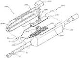
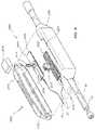
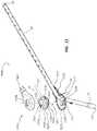
- FIG. 1is a perspective view of a steerable drainage device.
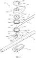
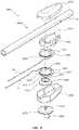
- FIG. 2is a perspective, exploded, top view of a portion of the steerable drainage device of FIG. 1 .
- FIG. 3is a perspective, exploded, bottom view of a portion of the steerable drainage device of FIG. 1 .
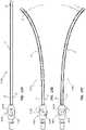
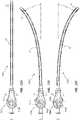
- FIG. 4 Ais a top cross-sectional view of the steerable drainage device of FIG. 1 in a straight configuration.
- FIG. 4 Bis a top cross-sectional view of the steerable drainage device of FIG. 1 , where the device is bent in a first direction.
- FIG. 4 Cis a top cross-sectional view of the steerable drainage device of FIG. 1 , where the device is bent in a second direction.
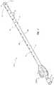
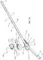
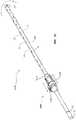
- FIG. 5is a perspective view of a steerable drainage device.
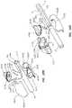
- FIG. 6is a perspective, exploded, view of the steerable drainage device of FIG. 5 .
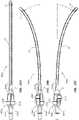
- FIG. 7 Ais a top cross-sectional/cut-away view of the steerable drainage device of FIG. 5 in a straight configuration.
- FIG. 7 Bis a top cross-sectional/cut-away view of the steerable drainage device of FIG. 5 , where the device is bent in a first direction.
- FIG. 7 Cis a top cross-sectional/cut-away view of the steerable drainage device of FIG. 5 , where the device is bent in a second direction.
- FIG. 8is a perspective view of a steerable drainage device.
- FIG. 9 Ais a perspective, exploded, top view of a portion of the steerable drainage device of FIG. 8 .
- FIG. 9 Bis a perspective, exploded, bottom view of a portion of the steerable drainage device of FIG. 8 .
- FIG. 10 Ais a partial cross-sectional top view of the steerable drainage device of FIG. 8 in a straight configuration.
- FIG. 10 Bis a partial cross-sectional top view of the steerable drainage device of FIG. 8 , where the device is bent in a first direction.
- FIG. 10 Cis a partial cross-sectional top view of the steerable drainage device of FIG. 8 , where the device is bent in a second direction.
- FIG. 11is a perspective view of a steerable drainage device.
- FIG. 12is a perspective, exploded, view of the steerable drainage device of FIG. 11 .
- FIG. 12 Ais a perspective, exploded view of a tension control member of the steerable drainage device of FIG. 11 .
- FIG. 13 Ais a top cross-sectional view of the steerable drainage device of FIG. 11 in a straight configuration.
- FIG. 13 Bis a top cross-sectional view of the steerable drainage device of FIG. 11 , where the device is bent in a first direction.
- FIG. 13 Cis a top cross-sectional view of the steerable drainage device of FIG. 11 , where the device is bent in a second direction.
- FIG. 14is a perspective view of a steerable drainage device.
- FIG. 15is a perspective, exploded, view of the steerable drainage device of FIG. 14 .
- FIG. 16 Ais a top partial cross-sectional view of the steerable drainage device of FIG. 14 in a straight configuration.
- FIG. 16 Bis a top partial cross-sectional view of the steerable drainage device of FIG. 14 , where the device is bent in a first direction.
- FIG. 16 Cis a top partial cross-sectional view of the steerable drainage device of FIG. 14 , where the device is bent in a second direction.
- FIG. 17is a perspective view of a steerable drainage device.
- FIG. 18 Ais a perspective, exploded, bottom view of a portion of the steerable drainage device of FIG. 17 .
- FIG. 18 Bis a perspective, exploded, top view of a portion of the steerable drainage device of FIG. 17 .
- FIG. 19 Ais a top partial cross-sectional view of the steerable drainage device of FIG. 17 in a straight configuration.
- FIG. 19 Bis a top partial cross-sectional view of the steerable drainage device of FIG. 17 , where the device is bent in a first direction.
- FIG. 19 Cis a top partial cross-sectional view of the steerable drainage device of FIG. 17 , where the device is bent in a second direction.
- FIG. 20is a perspective view of a steerable drainage device.
- FIG. 21is a perspective, exploded, view of the steerable drainage device of FIG. 20 .
- FIG. 22 Ais a top partial cross-sectional view of the steerable drainage device of FIG. 20 in a straight configuration.
- FIG. 22 Bis a top partial cross-sectional view of the steerable drainage device of FIG. 20 , where the device is bent in a first direction.
- FIG. 22 Cis a top partial cross-sectional view of the steerable drainage device of FIG. 20 , where the device is bent in a second direction.
- FIG. 23is a perspective view of a steerable drainage device.
- FIG. 24is a perspective, exploded, view of the steerable drainage device of FIG. 23 .
- FIG. 25 Ais a top partial cross-sectional view of the steerable drainage device of FIG. 23 in a straight configuration.
- FIG. 25 Bis a top partial cross-sectional view of the steerable drainage device of FIG. 23 , where the device is bent in a first direction.
- FIG. 25 Cis a top partial cross-sectional view of the steerable drainage device of FIG. 23 , where the device is bent in a second direction.
- FIG. 26is a perspective view of a steerable drainage device.
- FIG. 27is a perspective, exploded, view of the steerable drainage device of FIG. 26 .
- FIG. 28 Ais a top partial cross-sectional view of the steerable drainage device of FIG. 26 in a straight configuration.
- FIG. 28 Bis a top partial cross-sectional view of the steerable drainage device of FIG. 26 , where the device is bent in a first direction.
- FIG. 28 Cis a top partial cross-sectional view of the steerable drainage device of FIG. 26 , where the device is bent in a second direction.
- Elongate medical devicesmay be inserted into body cavities and vessels to perform diagnostic and therapeutic procedures. In some instances, positioning of the elongate device may be facilitated by a steering mechanism configured to bend or rotate an end of the elongate device such that the elongate device can be directed to, and positioned at, a targeted location.
- steerable elongated devicescomprise balloon dilation catheters, stent delivery catheters, endoscopes, and drainage tubes, such as chest tubes.
- a chest tubemay be steered to a targeted location within the pleural space to drain the space of excess fluid.
- the steerable drainage devices disclosed hereincomprise two wires or flexible members running parallel over the length of a catheter or tube.
- the distal ends of the wiresmay be attached to a distal end of the catheter or tube.
- the proximal ends of the wiresmay be operatively coupled to a tension control member or steering device.
- the tension control memberis configured to selectively apply tension to the wires such that the end of the catheter or tube bends.
- Coupled torefers to any form of interaction between two or more entities, including mechanical, electrical, magnetic, electromagnetic, fluid, and thermal interaction.
- Two componentsmay be coupled to each other even though they are not in direct contact with each other.
- two componentsmay be coupled to each other through an intermediate component.
- distal and proximalare given their ordinary meaning in the art. That is, the distal end of a medical device means the end of the device furthest from the practitioner during use.
- the proximal endrefers to the opposite end, or the end nearest the practitioner during use.
- the proximal end of the drainage tuberefers to the end disposed outside of the patient and the distal end refers to the opposite end, the end disposed inside the patient.
- Fluidis used in its broadest sense, to refer to any fluid, including both liquids and gases as well as solutions, compounds, suspensions, etc., which generally behave as fluids.
- wireor “flexible member” are broad terms that encompasses any type of flexible elongated material capable of providing a pulling force and encompasses, by way of example and not limitation, metal wire, coated wire, polymer wire, woven or braided wire, string, yarn, line, cable, filament, lace, and cord.
- FIGS. 1 - 28 Cillustrate different views of several embodiments of steerable drainage devices and related components. These drainage devices and steering systems may be used in connection with a variety of drainage devices, including, for example, a chest tube.
- the steerable drainage devices disclosed hereinare not limited to use with chest tubes, but may be used with any suitable elongate medical device, such as balloon dilatation catheters, stent delivery catheters, endoscopes, drainage tubes, etc., including devices configured to be directed to a target location.
- each devicemay be coupled to, or shown with, additional components not included in every view. Further, in some views only selected components are illustrated, to provide detail into the relationship of certain components. Some components may be shown in multiple views, but not discussed in connection with every view. Disclosure provided in connection with any figure or figure is relevant and may be analogously applied to disclosure provided in connection with any other figure or embodiment.
- FIGS. 1 - 4 Cdepict a steerable drainage device 1000 .
- the steerable drainage device 1000comprises a drainage tube 10 and a tension control member or steering device 1050 .
- the drainage tube 10may comprise a proximal end 11 , a distal end 12 , a wall 13 , a central lumen 14 , and at least one closed lumens 18 a , 18 b .
- the drainage tube 10may comprise a single central lumen 14 forming a central passage through the drainage tube 10 and two closed lumens 18 disposed in the wall 13 of the drainage tube 10 .
- the drainage tube 10may be formed of a flexible polymer material, such as polyvinyl chloride (PVC), polyurethane; silicone, etc. . . . .
- the drainage tubemay further comprise a plurality of openings 15 near the distal end 12 .
- the proximal end 11 of the drainage tube 10may be configured for attachment to a vacuum source.
- the distal end 12 of the drainage tube 10may be configured to be detectable by an imaging system, such as x-ray, fluoroscopy, ultrasound, etc.
- the distal end 12may comprise materials that are radiopaque, such as barium sulfate, bismuth trioxide, titanium bands, etc. In other embodiments, the distal end 12 may comprise materials or surface modifications that are configured to reflect ultrasound waves.
- a first wire or flexible member 16 and a second wire or flexible member 17may be inserted into the closed lumens 18 a , 18 b that are separate from the central lumen 14 of the drainage tube 10 .
- the first and second wires 16 , 17may be attached to the distal end 12 of the drainage tube 10 .
- the closed lumens 18 a , 18 b and wires 16 , 17may be positioned on opposing sides of the drainage tube 10 .
- Coupling of the wires 16 , 17 to the drainage tube 10 at or near the distal end 12may be accomplished by one of any number of attachment configurations.
- each wire 16 , 17may be wrapped around a portion of the distal end 12 of the drainage tube 10 .
- Each wire 16 , 17may then be attached to itself at a joint, such as by a weld joint, a swaged or crimped joint, a knot, or another joint.
- the drainage tube 10may further comprise a tip comprising passages sized similar to the diameters of the wires 16 , 17 .
- the first wire 16 and the second wire 17may extend through the passages of the tip, and a stop, such as a weld bead or a swaged member, may be attached to a free end of each wire 16 , 17 to prevent the free end of each wire 16 , 17 from passing through the passages.
- a single wiremay be utilized as the first wire 16 and the second wire 17 such that the single wire loops from a first proximal end to the distal end 12 of the drainage tube 10 and back to a second proximal end.
- the distal end 12 of the drainage tube 10may be displaced by manipulation of the wires 16 , 17 at the proximal end 11 of the drainage tube 10 .
- a tensile forceis applied to the first wire 16 (e.g., when a pulling force is applied to the first wire 16 by a tension control member, such as tension control member 1050 )
- a first side of the drainage tube 10may be put into compression.
- the drainage tube 10may bend in a first direction ⁇ .
- a second side of the drainage tube 10may be put into compression.
- the drainage tubemay bend in a second direction ⁇ .
- a drainage tubemay include only a first wire and not include a second wire.
- a drainage tubemay include a first wire, a second wire, and any number of additional wires.
- the more wires that are includedthe greater the range of motion that may be achieved with a distal end of a drainage tube.
- two opposing wires configured to provide displacement in two directionsmay provide sufficient range of motion for many therapeutic uses, such as for draining fluid from the body cavity, for example, a pleural cavity.
- the steerable drainage device 1000may comprise a tension control member 1050 .
- the tension control member 1050may be configured to apply selective tension to the wires 16 , 17 such that the distal end 12 of the drainage tube 10 bends in a direction of a side of the drainage tube 10 where the tensioned wire 16 , 17 is located, as described above.
- the tension control member 1050may comprise a housing 1030 , a knob 1056 , a drive capstan 1053 , a first spool 1054 , a second spool 1055 , and a locking member 1051 .
- the tension control member 1050may be coupled to the drainage tube 10 adjacent the proximal end 11 .
- the tension control member 1050may be fixedly coupled to the drainage tube 10 such that the tension control member 1050 is anchored to the drainage tube 10 to allow for application of tension to the wires 16 , 17 .
- a ring(not shown) may be fixedly coupled to the drainage tube 10 adjacent the proximal end 11 and the housing 1030 disposed over the ring such that the tension control member 1050 is prevented from longitudinal displacement relative to the drainage tube 10 .
- Each embodiment of the steerable drainage device disclosed hereinmay be configured in a similar manner.
- the drainage tube 10may be axially aligned with a longitudinal axis of the tension control member 1050 such that the drainage tube 10 passes through at least a portion of the housing 1030 .
- the housing 1030may be configured to be gripped by a hand of the healthcare worker.
- the housing 1030may be sized to be comfortably secured to a patient's body for time periods hours to days.
- the tension control member 1050may be at least partially disposed within the housing 1030 .
- the knob 1056may be configured to be gripped by a hand of a healthcare worker such that the knob 1056 may be rotated in a first direction and a second direction. As detailed below, the knob 1056 may be configured to lock or maintain a rotational position after rotational displacement.
- the knob 1056may comprise a handle 1065 and a shaft 1066 .
- the handle 1065may be shaped in any suitable shape to be gripped by the healthcare worker. For example, as illustrated in FIG. 2 , the handle 1065 may be in the shape of an arrow such that the knob 1056 may be gripped by the healthcare worker and may indicate a direction the drainage tube 10 may be bent.
- the shaft 1066may be keyed to match with a passage 1062 through the drive capstan 1053 such that when the knob 1056 is rotated in first ⁇ and second directions A (as shown in FIG. 1 ), the drive capstan 1063 is rotated in the same directions.
- the shaft 1066is in a shape of an arrow and the passage 1062 through the drive capstan 1053 has a similar shape such that rotation of the knob 1056 causes rotation of the drive capstan 1053 in the same direction.
- the knob 1056may be configured to be removable from the tension control member 1050 following rotation and locking of the tension control member 1050 , wherein the distal end 12 of the drainage tube 10 is maintained in an arcuate configuration. By removing the knob 1056 , the patient or non-healthcare worker cannot change the curvature of the drainage tube 10 by rotating the tension control member 1050 once it has been set by the healthcare worker.
- the drive capstan 1053may comprise a disk 1067 and a cylinder 1068 extending from the disk 1067 .
- the drive capstan 1053may be circular in shape.
- the keyed passage 1062is configured to pass through the disk 1067 .
- the cylinder 1068can be sized to be received within a first central passage 1047 of the first spool 1054 and within a second central passage 1046 of the second spool 1055 .
- a drive tab 1069may extend radially outward from the cylinder 1068 and be configured to couple with a first rotation tab 1049 of the first spool 1054 and a second rotation tab 1048 of the second spool 1055 .
- a lower end of the cylinder 1068may comprise a plurality of recesses 1063 disposed in a wall of the cylinder 1068 .
- the recesses 1063may be configured to be releasably coupled to a peg 1064 of the locking member 1051 such that the tension control member 1050 may be locked in a rotated configuration.
- the first spool 1054is circular in shape and comprises the first central passage 1047 , a first groove 1060 , and the first rotation tab 1049 .
- the first central passage 1047is sized to receive the cylinder 1068 of the drive capstan 1053 .
- the first groove 1060may be disposed around a periphery of the first spool 1054 and be sized to receive the first wire 16 .
- the first rotation tab 1049may extend radially inward into the first central passage 1047 and extend downward from the first spool 1054 . In the embodiment of FIGS.
- the first rotation tab 1049is configured to couple with the drive tab 1069 of the drive capstan 1053 and the second rotation tab 1048 of the first spool as the tension control member 1050 is rotated in the first direction ⁇ .
- the first wire 16may be coupled to the first spool 1054 utilizing any suitable technique.
- the second spool 1055is circular in shape and comprises the second central passage 1046 , a second groove 1061 , and the second rotation tab 1048 .
- the second central passage 1046is sized to receive the cylinder 1068 of the drive capstan 1053 .
- the second groove 1061is disposed around a periphery of the second spool 1055 and is sized to receive the second wire 17 .
- the second rotation tab 1048extends radially inward into the second central passage 1046 and extends upward from the second spool 1055 .
- the second rotation tab 1048is configured to couple with the drive tab 1069 of the drive capstan 1053 and the first rotation tab 1049 of the first spool 1054 as the tension control member 1050 is rotated in the second direction ⁇ .
- the second wire 17may be coupled to the second spool 1055 utilizing any suitable technique.
- the locking member 1051comprises a body 1045 .
- the body 1045may comprise a first channel 1058 , a second channel 1059 , and a locking arm 1044 .
- the first channel 1058may be disposed on one side of the body 1045 and be sized to slideably receive the first wire 16 .
- the first channel 1058may be configured to direct the first wire 16 from one closed lumen 18 of the drainage tube 10 to the first groove 1060 of the first spool 1054 such that the first wire 16 at least partially wraps around the first spool 1054 in a first direction.
- the second channel 1059may be disposed on an opposing side of the body 1045 and be sized to slideably receive the second wire 17 .
- the second channel 1059may be configured to direct the second wire 17 from one closed lumen 18 of the drainage tube 10 to the second groove 1061 of the second spool 1055 such that the second wire 17 at least partially wraps around the second spool 1055 .
- the locking arm 1044comprises a first segment 1043 , an end segment 1042 , and a button 1041 .
- the locking arm 1044is configured as a cantilevered beam such that the locking arm 1044 extends across the body 1045 .
- An end of the first segment 1043is coupled to the body 1045 , and sides of the first segment 1043 may be moveable relative to the body 1045 .
- the button 1041is disposed between the first segment 1043 and the end segment 1042 and extend upward from the locking arm 1044 .
- An upper portion of the button 1041is configured to be depressible by an end of the shaft 1066 of the knob 1056 such that a lower portion of the button 1041 compresses the drainage tube 10 disposed underneath the button 1041 .
- the end segment 1042extends laterally from the button 1041 and is configured to move relative to the body 1045 .
- the end segmentcomprises the peg 1064 .
- the peg 1064is configured to be received and released by at least one recess 1063 of the drive capstan 1053 .
- the steerable drainage device 1000may be utilized to insert the drainage tube 10 into a body cavity, such as the pleural cavity to drain fluid from around the lungs.
- the steerable drainage device 1000may be used to direct the tip of the drainage tube 10 to a targeted location within the body cavity.
- the drainage tube 10may be inserted into the body cavity utilizing any suitable technique, such as through a thoracotomy or through an introducer.
- the distal end 12 of the drainage tube 10may be bent in the first ⁇ and second ⁇ directions by actuation of the tension control member 1050 such that the drainage tube 10 may be directed to the target location.
- the keyed shaft 1066 of the knob 1056is inserted through the keyed passage 1062 of the drive capstan 1053 and through the first central passage 1047 of the first spool 1054 and through the second central passage 1046 of the second spool 1055 .
- the knob 1056is depressed against the drive capstan 1053 .
- the end of the keyed shaft 1066engages with the button 1041 of the locking member 1051 such that the locking arm 1044 is displaced downward and away from the drive capstan 1053 .
- the button 1041engages and compresses the drainage tube 10 .
- the peg 1064 of the locking member 1051is displaced downward and displaced from the recess 1063 of the shaft 1066 of the knob 1056 such that the tension control member 1051 is unlocked and is rotatable by the healthcare worker.
- the handle 1065 of the knob 1056is grasped by the healthcare worker and rotated in the first direction ⁇ .
- Rotation of the knob 1056 in the first direction ⁇causes the drive capstan 1053 to be rotated in the first direction ⁇ due to the keyed coupling of the keyed shaft 1066 with the keyed passage 1062 .
- the drive tab 1069 of the drive capstan 1053engages the first rotation tab 1049 of the first spool 1054 such that the first spool 1054 is rotated in the first direction ⁇ .
- Rotation of the first spool 1054results in the first wire 16 sliding proximally through the first channel 1058 of the body 1045 and being received in the first groove 1060 such that the first wire 16 is at least partially wrapped around the first spool 1054 .
- a tension forceis applied to the first wire 16 .
- the tension forcein turn, compresses the drainage tube 10 along the side of the drainage tube 10 where the first wire 16 is disposed. Compression of the drainage tube 10 causes the distal end 12 to bend in the first direction ⁇ , forming an arcuate shape in a single plane.
- the drainage tube 10may be bent from about one degree to about 180 degrees or more in the first direction ⁇ .
- the curved drainage tube 10may be further advanced into the body cavity and directed to the target location. Adjustments to the amount of curvature of the drainage tube 10 are accomplished by further rotation of the knob 1056 in the first direction ⁇ to apply a greater tension force and to achieve more curvature of the drainage tube 10 or by rotation of the knob 1056 in the second direction ⁇ to achieve less curvature or curvature in the second direction. Rotation of the knob 1056 in the second direction ⁇ may release the tension force from the first wire 16 and apply the tension force to the second wire 17 . Rotation of the knob 1056 in the second direction ⁇ causes the drive tab 1069 to engage the second rotation tab 1048 of the second spool 1055 , resulting in rotation of the second spool 1055 in the second direction ⁇ .
- the second wire 17may slide through the second channel 1059 in a proximal direction and be received in the second groove 1061 as the second wire 17 is at least partially wrapped around the second spool 1055 .
- the tension force applied to the second wire 17compresses the drainage tube 10 along the side of the drainage tube 10 where the second wire 17 is disposed such that the drainage tube 10 is bent in the second direction ⁇ , forming an arcuate shape in a single plane.
- the drainage tube 10may be bent from about one degree to about 180 degrees in the second direction ⁇ .
- tensionmay be removed from the first wire 16 .
- the first wire 16may be displaced distally and unwrap from the first spool 1054 as the drainage tube 10 is straightened and/or bent in the second direction ⁇ .
- the tension control member 1050may or may not apply a push force to the first wire 16 .
- the first spool 1054 and the second spool 1055may be configured to rotate separately such that rotation of one spool in the first ⁇ or second ⁇ direction does not cause the other spool to be rotated in the same direction to the same degree of rotation.
- the knob 1056After rotation, adjustment, or placement, downward pressure on the knob 1056 may be released and the knob 1056 may be removed by the healthcare worker.
- the button 1041 of the locking arm 1044may be forced upward by the resiliency of the drainage tube 10 .
- the peg 1064 of the locking arm 1044may be disposed into one of the plurality of recesses 1063 of the drive capstan 1053 such that the tension control member 1050 is in a rotationally locked configuration and the drainage tube 10 is maintained in an arcuate configuration.
- FIGS. 5 - 7 Cdepict an embodiment of a steerable drainage device 2000 that resembles the steerable drainage device 1000 described above in certain respects. Accordingly, like features are designated with like reference numerals, with the leading digit incremented to “2.”
- the embodiment depicted in FIGS. 5 - 7 Cincludes a tension control member 2050 that may, in some respects, resemble the tension control member 1050 of FIGS. 1 - 4 C .
- Relevant disclosure set forth above regarding similarly identified featuresthus may not be repeated hereafter.
- specific features of the steerable drainage device 1000 and related components shown in FIGS. 1 - 4 Cmay not be shown or identified by a reference numeral in the drawings or specifically discussed in the written description that follows.
- Each disclosed embodiment of the steerable drainage devicemay comprise a particular mechanism configured to apply tension to wires and bend an end of a tube in two directions but disclosure about application of the various embodiments in use is analogous to all disclosed embodiments.
- the steerable drainage device 2000comprises the drainage tube 10 as previously described and a tension control member 2050 disposed adjacent the proximal end 11 of the drainage tube 10 .
- the tension control member 2050comprises a housing 2030 , a button 2074 and a linear displacement mechanism 2070 .
- the housing 2030may be configured to be grasped or held by the hand of a healthcare worker.
- the housing 2030comprises a longitudinal passage 2078 with openings at a proximal end and a distal end such that the drainage tube 10 is partially disposed within the passage 2078 .
- the housing 2030comprises a left half and a right half.
- the two halvesmay be separate components and coupled together using any suitable technique, or the two halves may be coupled together with a hinge, such as a living hinge.
- An opening 2077is disposed in the housing 2030 .
- the linear displacement mechanism 2070comprises a first rack 2071 , a second rack 2072 , and a gear 2073 .
- the gear 2073comprises a plurality of teeth around a perimeter and is fixedly secured in a position within the passage 2078 between the first rack 2071 and the second rack 2072 .
- the first and second racks 2071 , 2072comprise a plurality of teeth extending along a length of the racks 2071 , 2072 .
- the teeth of the racks 2071 , 2072are configured to mesh with the teeth of the gear 2073 .
- the racks 2071 , 2072may comprise slots 2076 extending longitudinally along at least a portion of the length of the racks 2071 , 2072 .
- the slots 2076may be configured to facilitate coupling of the first and second wires 16 , 17 to the first and second racks 2071 , 2072 , respectively. For example, as shown in FIG. 6 , proximal ends of the first and second wires 16 , 17 are looped through the slots 2076 .
- the button 2074is operably coupled to the first rack 2071 and disposed within the opening 2077 of the housing 2030 .
- the button 2074has a substantially square shape and comprise walls that taper radially outward from a top surface.
- the walls of the button 2074are configured to frictionally engage with matching tapered walls of the opening 2077 such that linear movement of the button 2074 is restricted.
- the opening 2077is configured to retain the button 2074 at least partially within the passage 2078 of the housing 2030 .
- the width of the opening 2077 at an outer surface of the housing 2030may be less than a width of the wall of the button 2074 at a point below a top surface of the button 2074 .
- a biasing member 2075is disposed between the button 2074 and the first rack 2071 .
- the biasing member 2075may be any resilient component, such as a coiled spring, a leaf spring, an elastomeric disk, etc.
- the steerable drainage device 2000may be utilized to insert the drainage tube 10 into a body cavity, such as the pleural cavity to drain fluid from around the lungs, and direct the tip of the drainage tube 10 to a targeted location within the body cavity.
- the drainage tube 10may be inserted into the body cavity utilizing any suitable technique, such as through a thoracotomy or through an introducer.
- the distal end 12 of the drainage tube 10may be bent in the first ⁇ or second ⁇ direction by actuation of the tension control member 2050 such that the drainage tube 10 may be directed to the target location.
- the housing 2030 of the tension control member 2050is grasped or held by the hand of the healthcare worker.
- a suitable imaging systemsuch as x-ray, fluoroscopy, or ultrasound
- Adjustments to the insertion directionmay be made by actuation of the tension control member 2050 .
- Downward pressure on the button 2074is applied by a finger of the healthcare worker such that the biasing member 2075 is compressed and the wall of the button 2074 released from frictional engagement with the wall of the opening 2077 of the housing 2030 .
- Proximal displacement of the button 2074 by the finger of the healthcare workercauses the first rack 2071 to be displaced proximally and tension to be applied to the first wire 16 such that the distal end 12 of the drainage tube 10 is bent in a first direction ⁇ .
- Proximal displacement of the first rack 2071results in rotation of the gear 2073 and distal displacement of the second rack 2072 as the teeth of the gear 2073 and the racks 2071 , 2072 mesh.
- Distal displacement of the button 2074 by the finger of the healthcare workercauses the first rack 2071 to be displaced distally and the second rack 2072 to be displaced proximally as the gear 2073 is rotated such that tension is applied to the second wire 17 .
- the tension on the second wire 17causes the distal end 12 of the drainage tube 10 to be bent in a second direction ⁇ .
- Distal displacement of the first rack 2071may result in rotation of the gear 2073 in a second direction and proximal displacement of the second rack 2072 as the teeth of the gear 2073 and the racks 2071 , 2072 mesh.
- the button 2074is displaced upward such that the wall of the button 2074 may frictionally engage the wall of the opening 2077 .
- the button 2074may be locked in a longitudinal position such that the distal end 12 of the drainage tube 10 remains bent in either the first ⁇ or second direction ⁇ .
- FIGS. 8 - 10 Cillustrate a steerable drainage device 3000 comprising the drainage tube 10 as previously described and a tension control member 3050 disposed adjacent the proximal end 11 of the drainage tube 10 .
- the tension control member 3050comprises a housing 3030 , a button 3080 , a distal pulley 3082 , and a proximal pulley 3083 .
- the housing 3030is configured to be grasped or held by the hand of a healthcare worker.
- the housing 3030comprises a longitudinal passage 3086 with openings at a proximal end and a distal end such that the drainage tube 10 may be partially disposed within the passage 3086 and in alignment with a longitudinal axis of the housing 3030 .
- the housing 3030comprises a left half and a right half.
- the two halvesmay be separate components and coupled together using any suitable technique, or the two halves may be coupled together with a hinge, such as a living hinge.
- a longitudinal slot 3087is disposed in a top portion of the housing 3030 .
- a plurality of downwardly directed teeth 3081extend along at least a portion of the periphery of the slot 3087 .
- the button 3080comprises an upper portion 3088 , a shaft 3085 , and a lower portion 3084 .
- the upper portion 3088may be substantially circular or oblong in shape.
- the upper portion 3088is configured to be slideably disposed within a recess 3094 of the housing 3030 .
- the upper portion 3088may be configured to be engaged by a finger of a healthcare worker to depress and slide the button 3080 proximally and distally relative to the housing 3030 .
- the upper portion 3088may comprise any suitable grip enhancing feature, such as bumps, recesses, surface texturing, elastomeric layer, etc.
- the shaft 3085extends from a bottom surface of the upper portion 3088 .
- the shaft 3085is sized to be longitudinally displaceable within the slot 3087 of the housing 3030 .
- the first and second wires 16 , 17may be coupled to the shaft 3085 using any suitable technique.
- the shaft 3085may comprise a wire passage 3091 .
- the first wire 16may pass through the passage 3091 proximally.
- An end of the first wire 16may comprise a crimp, weld bead, etc. such that the end of the first wire 16 may be prevented from passing back through the passage 3091 .
- the second wire 17may pass through the passage 3091 distally.
- An end of the second wire 17may comprise a crimp, weld bead, etc. such that the end of the second wire 17 may be prevented from passing back through the passage 3091 .
- the lower portion 3089is coupled to the shaft 3085 .
- the lower portion 3089comprises a plurality of upwardly directed teeth 3090 disposed on lateral sides of the lower portion 3084 .
- the teeth 3090are configured to mesh with the teeth 3081 of the housing 3030 .
- the distal pulley 3082is disposed adjacent a distal end of the passage 3086 .
- the proximal pulley 3083is disposed adjacent a proximal end of the passage 3086 .
- the distal and proximal pulleys 3082 , 3083are configured to direct the first and second wires 16 , 17 , respectively, to the button 3080 .
- the first wire 16may pass around the distal pulley 3082 such that the first wire 16 may be coupled to a distal side of the button 3080 .
- the second wire 17may pass around the proximal pulley 3083 such that the second wire 17 may be coupled to a proximal side of the button 3080 .
- the steerable drainage device 3000may be utilized to insert the drainage tube 10 into a body cavity, such as the pleural cavity to drain fluid from around the lungs, and direct the tip of the drainage tube 10 to a targeted location within the body cavity.
- the drainage tube 10may be inserted into the body cavity utilizing any suitable technique, such as through a thoracotomy or through an introducer.
- the distal end 12 of the drainage tube 10may be bent in the first ⁇ and second ⁇ directions by actuation of the tension control member 3050 such that the drainage tube 10 may be directed to the target location.
- the housing 3030 of the tension control member 3050may be grasped or held by the hand of the healthcare worker.
- a suitable imaging systemsuch as x-ray, fluoroscopy, or ultrasound
- Adjustments to the insertion directionmay be made by actuation of the tension control member 3050 .
- Downward pressure on the button 3080may be applied by a finger of the healthcare worker such that the button 3080 is displaced downward.
- the teeth 3090 of a lower portion 3089may unmesh from the teeth 3081 of the housing 3030 such that the button 3080 may be longitudinally slideable. Additionally, a bottom surface of the lower portion 3089 may engage with a wall of the drainage tube 10 and compress the drainage tube 10 .
- Proximal displacement of the button 3080 by the finger of the healthcare workercauses tension to be applied to the first wire 16 such that the distal end 12 of the drainage tube 10 is bent in a first direction ⁇ .
- Distal displacement of the button 3080 by the finger of the healthcare workercauses tension to be applied to the second wire 17 such that the distal end 12 of the drainage tube 10 is bent in a second direction ⁇ .
- the button 3080is biased upward such that the teeth 3090 of the lower portion 3089 mesh with the teeth 3081 of the housing 3030 .
- the button 2080is locked in a longitudinal position such that the distal end 12 of the drainage tube 10 remains bent in either the first or second direction.
- FIGS. 11 - 13 Cillustrate a steerable drainage device 4000 comprising the drainage tube 10 as previously described and a tension control member 4050 disposed adjacent the proximal end 11 of the drainage tube 10 .
- the tension control member 4050comprises a housing 4030 , an inner shaft 4101 , a first nut 4102 , a second nut 4103 , and end caps 4110 .
- the inner shaft 4101comprises a passage 4111 , rails 4109 , channels 4108 , and flanges 4112 .
- the inner shaft 4101may be substantially a hollow cylinder.
- the drainage tube 10is disposed through the passage 4111 such that the drainage tube 10 extends beyond a proximal end and a distal end of the inner shaft 4101 and is longitudinally aligned with a longitudinal axis of the inner shaft 4101 .
- the inner shaft 4101is fixedly coupled to the drainage tube 10 .
- Two or more rails 4109are disposed opposing one another on an outer surface of the inner shaft 4101 .
- the rails 4109extend longitudinally along at least a portion of the length of the inner shaft 4101 .
- Channels 4108are disposed in the outer surface of the inner shaft 4101 adjacent the rails 4109 .
- the channels 4108extend longitudinally along the length of the rails 4109 .
- Flanges 4112are disposed at a proximal end and a distal end of the rails 4109 .
- the flanges 4112extend radially outward from the outer surface of the inner shaft 4101 .
- the first nut 4102 and the second nut 4103are operably coupled to the inner shaft 4101 .
- the nuts 4102 , 4103may be formed in a semi-circular shape.
- the nuts 4102 , 4103comprise a tab 4113 configured to be slideably disposed within the channels 4108 .
- the nuts 4102 , 4103are disposed on the inner shaft 4101 such that they oppose one another on the sides of the inner shaft 4101 .
- the nuts 4102 , 4103comprise an external, male thread 4104 .
- the male thread 4104 of the first nut 4102is be oriented in a clockwise direction.
- the male thread 4104 of the second nut 4103is oriented in a counterclockwise direction.
- the nuts 4102 , 4103are configured to be coupled to the wires 16 , 17 in any suitable manner.
- the nuts 4102 , 4103 and the flanges 4112may comprise small wire passages 4115 .
- the wires 16 , 17may pass through the wire passages 4115 .
- a crimp, weld bead, etc.may be formed on the end of the wires 16 , 17 such that a diameter of the end of the wires 16 , 17 is larger than a diameter of the wire passages 4115 .
- the housing 4030may be configured to be grasped and rotated by the hand of a healthcare worker.
- the housing 4030comprises a left half and a right half substantially forming a cylinder.
- the two halvesmay be separate components and coupled together using any suitable technique, or the two halves may be coupled together with a hinge, such as a living hinge.
- the housing 4030is disposed around a portion of the inner shaft 4101 .
- the housing 4030comprises a clockwise internal female thread 4106 and an internal counterclockwise internal female thread 4107 disposed in an inside surface.
- the clockwise internal female thread 4106 and the counterclockwise female thread 4107are configured to slideably receive the clockwise oriented male thread 4104 and the counterclockwise oriented male thread 4105 of the first nut 4102 and the second nut 4103 , respectively.
- the ends of the housing 4030are configured to couple with the flanges 4112 such that the housing 4030 is rotatable around the longitudinal axis of the inner shaft 4101 .
- the end caps 4110are configured to be disposed over the ends of the inner shaft 4101 such that the housing 4030 is retained in position around the inner shaft 4101 .
- the steerable drainage device 4000may be utilized to insert the drainage tube 10 into a body cavity, such as the pleural cavity to drain fluid from around the lungs, and direct the tip of the drainage tube 10 to a targeted location within the body cavity.
- the drainage tube 10may be inserted into the body cavity utilizing any suitable technique, such as through a thoracotomy or through an introducer.
- the distal end 12 of the drainage tube 10may be bent in the first and/or second direction by actuation of the tension control member 4050 such that the drainage tube 10 may be directed to the target location.
- the housing 4030 of the tension control member 4050may be grasped or held by the hand of the healthcare worker. Utilizing a suitable imaging system, such as x-ray, fluoroscopy, or ultrasound, a drainage tube 10 insertion direction may be determined. Adjustments to the insertion direction may be made by actuation of the tension control member 4050 .
- a suitable imaging systemsuch as x-ray, fluoroscopy, or ultrasound
- FIGS. 14 - 16 Cillustrate a steerable drainage device 5000 comprising the drainage tube 10 as previously described and a tension control member 5050 disposed adjacent the proximal end 11 of the drainage tube 10 .
- the tension control member 5050comprises a housing 5030 , a knob 5121 , and a locking member 5125 .
- the housing 5030is configured to be grasped and held by the hand of a healthcare worker.
- the housing 5030comprises an upper portion 5129 , a lower portion 5130 , and a cavity 5131 .
- the upper and lower portions 5129 , 5130may be separate components and coupled together using any suitable technique, or they may be coupled together with a hinge, such as a living hinge.
- the cavity 5131comprises a distal opening 5132 and a lower opening 5133 .
- the drainage tube 10may be partially disposed within the cavity 5131 such that a portion of the drainage tube 10 extends distally from the distal opening 5132 and a portion extends downwardly and proximally from the lower opening 5133 .
- the housing 5030further comprises the locking member 5125 comprising an arm 5128 and arm teeth 5126 .
- the arm 5128is disposed in the upper portion 5129 and extends proximally from a distal end of the upper portion 5129 .
- the arm 5128is configured in a cantilevered configuration such that the arm 5128 is configured to flex in a vertical plane.
- the arm teeth 5126are disposed at a distal end of the arm 5128 .
- the knob 5121comprises a handle 5122 , a shaft 5123 , and locking teeth 5124 .
- the handle 5122is disposed on the top portion of the knob 5121 .
- the handle 5122is configured to be grasped by the hand of the healthcare worker such that the knob 5121 may be rotated.
- the handle 5122may comprise an elongated vertical portion with a length substantially equivalent to the diameter of the upper portion of the knob 5121 .
- the handle 5122may comprise any suitable grip enhancing feature, such as bumps, dimples, surface texturing, elastomeric coating, etc.
- the shaft 5123extends downwardly from the upper portion of the knob 5121 into the cavity 5131 .
- the shaft 5123may be a cylinder.
- a plurality of locking teeth 5124circumferentially surround an upper portion of the shaft 5123 .
- the locking teeth 5124are configured to selectively meshed with the arm teeth 5126 such that the locking teeth 5124 and the arm teeth 5126 rotationally lock the knob 5121 .
- the first and second wires 16 , 17are coupled to the shaft 5123 in any suitable manner.
- the first and second wires 16 , 17may be coupled to the shaft 5123 utilizing a fastener, such as a screw, glue, etc.
- the first wire 16may be wrapped around the shaft 5123 in a first direction, and the second wire 17 may be wrapped around the shaft 5123 in a second direction.
- the shaft 5123may be rotatably coupled to the lower portion 5130 of the housing 5030 in any suitable manner, such as a screw.
- the steerable drainage device 5000may be utilized to insert the drainage tube 10 into a body cavity, such as the pleural cavity to drain fluid from around the lungs, and direct the tip of the drainage tube 10 to a targeted location within the body cavity.
- the drainage tube 10may be inserted into the body cavity utilizing any suitable technique, such as through a thoracotomy or through an introducer.
- the distal end 12 of the drainage tube 10may be bent in the first and/or second direction by actuation of the tension control member 5050 such that the drainage tube 10 may be directed to the target location.
- the housing 5030 of the tension control member 5050is grasped or held by the hand of the healthcare worker. Utilizing a suitable imaging system, such as x-ray, fluoroscopy, or ultrasound, a drainage tube 10 insertion direction may be determined. Adjustments to the insertion direction may be made by actuation of the tension control member 5050 .
- a suitable imaging systemsuch as x-ray, fluoroscopy, or ultrasound
- the handle 5122is grasped by the hand of the healthcare worker. Depression of the locking member 5125 unmeshes the arm teeth 5126 and the locking teeth 5124 such that the knob 5121 is rotatable. Rotation of the handle 5122 in a first direction ⁇ by the healthcare worker rotates the shaft 5123 in the first direction ⁇ . As the shaft 5123 is rotated in the first direction ⁇ , the first wire 16 is wrapped around the shaft 5123 such that tension may be applied to the first wire 16 . The tension on the first wire 16 facilitates bending of the distal end 12 of the drainage tube 10 in a first direction ⁇ . Rotation of the handle 5122 by the healthcare worker in the second direction ⁇ rotates the shaft 5123 in the second direction ⁇ .
- the second wire 17is wrapped around the shaft 5123 such that tension may be applied to the second wire 17 .
- the tension on the second wire 17facilitates bending of the distal end 12 of the drainage tube 10 in a second direction ⁇ .
- Release of the locking member 5125meshes the arm teeth 5126 and the locking teeth 5124 such that the knob 5121 is rotatably locked and the distal end 12 of the drainage tube 10 is maintained in an arcuate configuration.
- FIGS. 17 - 19 Cillustrate a steerable drainage device 6000 comprising the drainage tube 10 as previously described and a tension control member 6050 disposed adjacent the proximal end 11 of the drainage tube 10 .
- the tension control member 6050comprises a housing 6030 and a knob 6140 .
- the housing 6030is configured to be grasped and held by the hand of a healthcare worker.
- the housing 6030comprises a first portion 6147 , a second portion 6148 , and a cavity 6149 .
- the first and second portions 6147 , 6148may be separate components and coupled together using any suitable technique, or they may be coupled together with a hinge, such as a living hinge.
- the cavity 6149comprises a distal opening 6150 , a proximal opening 6151 in axial alignment with the distal opening 6150 , and a knob opening 6152 .
- the drainage tube 10may be partially disposed within the cavity 6149 such that a portion of the drainage tube 10 extends distally from the distal opening 6150 and a portion extends proximally from the proximal opening 6151 .
- the housing 6030further comprises a first rod 6144 and a second rod 6145 .
- the first rod 6144is disposed within the first portion 6147 of the housing 6030 such that a portion of the first rod 6144 is disposed within the cavity 6149 and opposing ends are disposed external to the cavity 6149 .
- the second rod 6145is disposed within the second portion 6148 of the housing 6030 such that a portion of the second rod 6145 is disposed within the cavity 6149 and opposing ends are disposed external to the cavity 6149 .
- the first and second rods 6144 , 6145are positioned with a tilted orientation such that lower ends of the first and second rods 6144 , 6145 are closer to a central, longitudinal axis of the housing 6030 than the upper ends.
- the knob 6140comprises a handle 6141 , a disk 6142 , and a wire tensioning block 6143 .
- the handle 6141is disposed on the top portion of the knob 6140 .
- the handle 6141is configured to be grasped by the hand of the healthcare worker such that the knob 6140 may be rotated.
- the handle 6141may comprise an elongated vertical portion with a length substantially equivalent to the diameter of the upper portion of the knob 6140 .
- the handle 6141may comprise any suitable grip enhancing feature, such as bumps, dimples, surface texturing, elastomeric coating, etc.
- the disk 6142extends downwardly from the upper portion of the knob 6140 into the cavity 6149 through the knob opening 6152 .
- the disk 6142has a circular shape.
- the disk 6142comprises a ring 6155 configured to be disposed in a circular channel 6154 of the housing 6030 .
- a plurality of detents 6146circumferentially surround a perimeter of the disk 6142 .
- the detents 6146are configured to frictionally engage a wall of the knob opening 6152 such that the knob 6140 is rotationally locked.
- the wire tensioning block 6143extends downwardly from the disk 6142 .
- the block 6143is disposed toward the perimeter of the disk 6142 such that the block 6143 is offset from a center point of the disk 6142 .
- the first and second wires 16 , 17may be coupled to a peripheral portion of the block 6143 in any suitable manner.
- the first wire 16is coupled to the block 6143 such that the wire 16 extends from the block 6143 toward the first rod 6144 and around the portion of the first rod 6144 disposed within the cavity 6149 .
- the second wire 17is coupled to the block 6143 such that the second wire 17 extends from the block 6143 toward the second rod 6145 and around the portion of the second rod 6145 disposed within the cavity 6149 .
- the steerable drainage device 6000may be utilized to insert the drainage tube 10 into a body cavity, such as the pleural cavity to drain fluid from around the lungs, and direct the tip of the drainage tube 10 to a targeted location within the body cavity.
- the drainage tube 10may be inserted into the body cavity utilizing any suitable technique, such as through a thoracotomy or through an introducer.
- the distal end 12 of the drainage tube 10may be bent in the first ⁇ and second ⁇ directions by actuation of the tension control member 6050 such that the drainage tube 10 may be directed to the target location.
- the housing 6030 of the tension control member 6050may be grasped or held by the hand of the healthcare worker. Utilizing a suitable imaging system, such as x-ray, fluoroscopy, or ultrasound, a drainage tube 10 insertion direction may be determined. Adjustments to the direction the distal end 12 of the drainage tube 10 is pointed may be made by actuation of the tension control member 6050 .
- a suitable imaging systemsuch as x-ray, fluoroscopy, or ultrasound
- the handle 6141is grasped by the hand of the healthcare worker.
- Rotation of the handle 6141 in a first direction by the healthcare worker with enough rotational force to overcome the frictional force of the detents 6146 against the housing 6030rotates the disk 6142 in the first direction ⁇ .
- the first wire 16is pulled by the block 6143 around the first rod 6144 such that tension is applied to the first wire 16 .
- the tension on the first wire 16facilitates bending of the distal end 12 of the drainage tube 10 in a first direction ⁇ .
- Rotation of the handle 6141 by the healthcare worker in the second direction ⁇rotates the disk 6142 in the second direction ⁇ .
- the second wire 17is pulled by the block 6143 around the second rod 6145 such that tension is applied to the second wire 17 .
- the tension on the second wire 17facilitates bending of the distal end 12 of the drainage tube 10 in a second direction ⁇ .
- FIGS. 20 - 22 Cillustrate a steerable drainage device 7000 comprising the drainage tube 10 as previously described and a tension control member 7050 disposed adjacent the proximal end 11 of the drainage tube 10 .
- the tension control member 7050comprises a housing 7030 and a knob 7130 .
- the housing 7030is configured to be grasped and held by the hand of a healthcare worker.
- the housing 7030comprises an upper portion 7169 , a lower portion 7170 , and a cavity 7171 .
- the upper and lower portions 7169 , 7170may be separate components and coupled together using any suitable technique, or they may be coupled together with a hinge, such as a living hinge.
- the cavity 7171comprises a distal opening 7172 , a lower opening 7173 , and a knob opening 7174 .
- the drainage tube 10may be partially disposed within the cavity 7171 such that a portion of the drainage tube 10 extends distally from the distal opening 7172 and a portion extends downwardly and proximally from the lower opening 7173 .
- the knob 7160comprises a handle 7161 , a disk 7162 , a shaft 7164 , and a locking teeth ring 7165 .
- the handle 7161is disposed on a top surface of the disk 7162 .
- the handle 7161is configured to be grasped by the hand of the healthcare worker such that the knob 7160 may be rotated.
- the handle 7161may comprise an elongated vertical portion with a length less than a diameter of the disk 7162 and less than a diameter of the knob opening 7174 .
- the handle 7161is disposed through the knob opening 7174 such that the handle 7161 may be grasped by the healthcare worker.
- the handle 7161may comprise any suitable grip enhancing feature, such as bumps, dimples, surface texturing, elastomeric coating, etc.
- the first and second wires 16 , 17are coupled to the disk 7162 in any suitable manner.
- the disk 7162comprises a first hook 7179 and a second hook 7180 disposed on the upper surface of the disk 7162 and adjacent a periphery of the disk 7162 .
- the first wire 16may comprise a looped end.
- the looped endis disposed over the first hook 7179 such that the first wire 16 is coupled to the disk 7162 .
- the second wire 17may comprise a looped end and the looped end is disposed over the second hook 7180 such that the second wire 17 is coupled to the disk 7162 .
- the disk 7162may further comprise an arcuate shaped hood 7181 disposed on the upper surface and adjacent the periphery of the disk 7162 .
- the hood 7181may extend around a portion of the periphery of the disk 7162 .
- the hood 7181is configured to provide a feature for wrapping of the first and second wires 16 , 17 when the knob 7160 is rotated.
- the teeth ring 7165extends from a bottom surface of the disk 7162 .
- the locking teeth ring 7165comprises a plurality of radially outwardly directed teeth 7167 .
- the diameter of the locking teeth ring 7165may be less than the diameter of the disk 7162 .
- the shaft 7164extends from the bottom surface of the disk 7162 .
- the shaft 7164may be a cylinder sized to couple with a rotation support 7176 disposed on an inner surface of the lower portion 7170 of the housing 7030 .
- the lower surface of the disk 7162may be supported by a vertical wall 7177 disposed on the inner surface of the lower portion 7170 .
- the vertical wall 7177is configured with an arcuate shape.
- the vertical wall 7177comprises at least one locking tooth 7178 extending radially inward.
- the locking tooth 7178is configured to mesh with the teeth 7167 of the locking teeth ring 7165 such that the knob 7160 can be rotationally locked.
- the knob 7160is rotatably coupled to the lower housing 170 using any suitable coupling device, such as a screw, a flat head pin, etc.
- the steerable drainage device 7000may be utilized to insert the drainage tube 10 into a body cavity, such as the pleural cavity to drain fluid from around the lungs, and direct the tip of the drainage tube 10 to a targeted location within the body cavity.
- the drainage tube 10may be inserted into the body cavity utilizing any suitable technique, such as through a thoracotomy or through an introducer.
- the distal end 12 of the drainage tube 10may be bent in the first and/or second direction by actuation of the tension control member 7050 such that the drainage tube 10 may be directed to the target location.
- the housing 7030 of the tension control member 7050is grasped or held by the hand of the healthcare worker. Utilizing a suitable imaging system, such as x-ray, fluoroscopy, or ultrasound, a drainage tube 10 insertion direction may be determined. Adjustments to the direction the distal end 12 of the drainage tube 10 is pointed may be made by actuation of the tension control member 7050 .
- a suitable imaging systemsuch as x-ray, fluoroscopy, or ultrasound
- the handle 7161is grasped by the hand of the healthcare worker.
- Rotation of the handle 7161 in a first direction by the healthcare worker with adequate rotational force to unmesh the locking tooth 7178 and the teeth 7127 of the locking ring 7165rotates the disk 7162 in the first direction ⁇ .
- the first wire 16is wrapped around the hood 7181 such that tension is applied to the first wire 16 .
- the tension on the first wire 16facilitates bending of the distal end 12 of the drainage tube 10 in a first direction ⁇ .
- Rotation of the handle 7161 by the healthcare worker in the second direction ⁇rotates the disk 7162 in the second direction ⁇ .
- the second wire 17is wrapped around the hood 7181 such that tension may be applied to the second wire 17 .
- the tension on the second wire 17facilitates bending of the distal end 12 of the drainage tube 10 in a second direction ⁇ .
- FIGS. 23 - 25 Cillustrate a steerable drainage device 8000 comprising the drainage tube 10 as previously described and a tension control member 8050 disposed adjacent the proximal end 11 of the drainage tube 10 .
- the tension control member 8050comprises a housing 8030 , a knob 8190 , a first disk 8195 , a second disk 8198 , and a locking member 8201 .
- the housing 8030is configured to be grasped and held by the hand of a healthcare worker.
- the housing 8030comprises an upper housing 8203 , a lower housing 8204 , and a cavity 8205 .
- the upper and lower housings 8023 , 8024may be separate components and coupled together using any suitable technique, or they may be coupled together with a hinge, such as a living hinge.
- the cavity 8025comprises a distal opening 8206 , a lower opening 8207 , and a knob opening 8208 .
- the drainage tube 10may be partially disposed within the cavity 8205 such that a portion of the drainage tube 10 extends distally from the distal opening 8206 and a portion extends downwardly and proximally from the lower opening 8207 .
- the knob 8190comprises a handle 8191 , a locking teeth ring 8192 , and a shaft 8194 .
- the handle 8191is disposed on a top surface of the locking teeth ring 8192 .
- the handle 8191is configured to be grasped by the hand of the healthcare worker such that the knob 8190 may be rotated.
- the handle 8191may comprise an elongated vertical portion with a length greater than a diameter of the locking teeth ring 8192 .
- the handle 8191is disposed through the knob opening 8208 such that the handle 8191 is graspable by the healthcare worker.
- the handle 8191may comprise any suitable grip enhancing feature, such as bumps, dimples, surface texturing, elastomeric coating, etc.
- the locking teeth ring 8192is disposed below the handle 8191 .
- the locking teeth ring 8192comprises a plurality of radially outwardly directed teeth 8193 .
- the shaft 8194extends downward from the locking teeth ring 8192 .
- the shaft 8194may be generally cylindrical in shape with a key tab 8210 extending radially outward from the shaft 8194 .
- the shaft 8194is coupled to the lower housing 8204 using any suitable fastener, such as a screw, flathead pin, etc., into a lower end of the shaft 8194 .
- the first disk 8195is disposed within the cavity 8205 .
- the first disk 8195comprises a first groove 8196 disposed about a perimeter and configured to receive the first wire 16 such that the first wire 16 can be wrapped around the first disk 8195 .
- the first disk 8195further comprises a first central passage 8197 configured in the shape of a truncated circle.
- the second disk 8198is disposed within the cavity 8205 below the first disk 8195 .
- the second disk 8198comprises a second groove 8199 disposed about a perimeter and configured to receive the second wire 17 such that the second wire 17 can be wrapped around the second disk 8198 in a second direction.
- the second disk 8198further comprises a second central passage 8200 configured in the shape of a truncated circle.
- the diameter of the first and second disks 8195 , 8198is less than the diameter of the locking teeth ring 8192 .
- An arcuate shaped retention wall 8213extends upwardly from an inner surface of the lower housing 8204 . The retention wall 8213 is configured to retain the first and second disks 8195 , 8198 in vertical alignment.
- the first and second wires 16 , 17may be coupled to the first and second disks 8195 , 8198 , respectively, in any suitable manner.
- the first and second wires 16 , 17are coupled to the first and second disks 8195 , 8198 , respectively, utilizing a plurality of stays 8211 .
- the locking member 8201is a cantilevered portion of the upper housing 8203 .
- the locking member 8201comprises a button 8214 and locking teeth 8202 .
- the locking teeth 8202are disposed at the proximal end of the locking member 8201 such that the locking teeth 8202 are configured to mesh with teeth 8193 of the locking teeth ring 8192 when the tension control member 8050 is in a locked configuration.
- the button 8214is disposed adjacent a proximal end of the locking member 8201 and extends upward above an outer surface of the upper housing 8203 .
- the button 8214is configured to be depressed by a finger of the healthcare worker such that the locking teeth 8202 unmesh from the teeth 8193 of the locking ring 8192 to allow rotation of the knob 8190 .
- the steerable drainage device 8000may be utilized to insert the drainage tube 10 into a body cavity, such as the pleural cavity to drain fluid from around the lungs, and direct the tip of the drainage tube 10 to a targeted location within the body cavity.
- the drainage tube 10may be inserted into the body cavity utilizing any suitable technique, such as through a thoracotomy or through an introducer.
- the distal end 12 of the drainage tube 10may be bent in first ⁇ and second ⁇ directions by actuation of the tension control member 8050 such that the drainage tube 10 may be directed to the target location.
- the housing 8030 of the tension control member 8050is grasped or held by the hand of the healthcare worker. Utilizing a suitable imaging system, such as x-ray, fluoroscopy, or ultrasound, a drainage tube insertion direction may be determined. Adjustments to the direction the distal end 12 of the drainage tube 10 is pointed may be made by actuation of the tension control member 8050 .
- a suitable imaging systemsuch as x-ray, fluoroscopy, or ultrasound
- the button 8214 of the locking member 8201is depressed by the finger of the healthcare worker such that the locking teeth 8202 of the locking member 8201 unmesh from the teeth 8193 of the locking ring 8192 , allowing the knob 8190 to be rotated in the first or second direction.
- the handle 8191is grasped by the hand of the healthcare worker. Rotation of the handle 8191 in the first direction ⁇ rotates the first disk 8195 and the second disk 8198 in the first direction ⁇ .
- the key tab 8210 of the shaft 8194engages the first truncated portions 8215 of the first central passage 8197 and the second central passage 8200 such that the first and second disks 8195 , 8198 rotate in the first direction ⁇ .
- the first disk 8195is rotated in the first direction ⁇
- the first wire 16is wrapped around the periphery in the first groove 8196 such that tension is applied to the first wire 16 and the distal end 12 of the drainage tube 10 is bent in a first direction ⁇ .
- the second disk 8198is rotated in the first direction ⁇
- the second wire 17is displaced from the second groove 8199 and pulled distally by bending of the drainage tube 10 in the first direction ⁇ .
- Rotation of the handle 8191 in the second direction ⁇rotates the first disk 8195 and the second disk 8198 in the second direction ⁇ .
- the key tab 8210 of the shaft 8194engages the second truncated portions 8216 of the first central passage 8197 and the second central passage 8200 such that the first and second disks 8195 , 8198 rotate in the second direction ⁇ .
- the second wire 17is wrapped around the periphery in the second groove 8199 such that tension is applied to the second wire 17 .
- the tension on the second wire 17facilitates bending of the distal end 12 of the drainage tube 10 in the second direction ⁇ .
- the first wire 16is displaced from the first groove 8196 and pulled distally by bending of the drainage tube 10 in the second direction.
- FIGS. 26 - 28 Cillustrate a steerable drainage device 9000 comprising the drainage tube 10 as previously described and a tension control member 9050 disposed adjacent the proximal end 11 of the drainage tube 10 .
- the tension control member 9050comprises a housing 9030 , a first button 9230 , a second button 9231 , and a pulley 9232 .
- the housing 9030is configured to be grasped and held by the hand of a healthcare worker.
- the housing 9030may be generally cylindrical in shape and comprise an upper housing 9235 , a lower housing 9236 , and a central passage 9245 .
- the upper and lower housings 9235 , 9236may be separate components and coupled together using any suitable technique, such as a snap fit, welding, gluing, etc., or they may be coupled together with a hinge, such as a living hinge.
- the central passage 9245comprises a distal opening 9249 and a proximal opening 9250 .
- the central passage 9245is sized such that the drainage tube 10 may be partially disposed within the central passage 9245 . A portion of the drainage tube 10 may extend distally from the distal opening 9249 and a portion may extend proximally from the proximal opening 9250 .
- the lower housing 9236further comprises a rear shroud 9237 disposed over the drainage tube 10 at a proximal end of the lower housing 9236 .
- the rear shroud 9237may be generally conical in shape.
- the rear shroud 9237may be coupled to a distal end of the upper housing 9235 and the lower housing 9236 using any suitable technique, such as snap fit, welding, gluing, etc.
- the upper housing 9235comprises two button channels 9239 .
- the button channels 9239are disposed on an exterior surface on lateral sides of the upper housing 9235 .
- the button channels 9239extend over a length of the upper housing 9235 and are L-shaped.
- the button channels 9239are disposed substantially parallel to one another.
- the upper housing 9235may comprise more than two button channels 9239 .
- the upper housing 9235comprises four button channels 9239 with two button channels 9239 disposed on each lateral half of the upper housing 9235 .
- the upper housing 9235may be configured as an integral component.
- the upper housing 9235may comprise two lateral halves.
- the first button 9230 and the second button 9231are configured to be slidingly coupled to the upper housing 9235 .
- the buttons 9230 , 9231comprise L-shaped rails 9240 disposed on an inside surface of the buttons 9230 , 9231 and extending longitudinally over a length of the buttons 9230 , 9231 .
- the L-shaped rails 9240are configured to be disposed into the button channels 9239 such that the L-shaped rails 9240 slide longitudinally within the button channels 9239 and are prevented from being radially displaced from the button channels 9239 .
- the buttons 9230 , 9231comprise at least one L-shaped rail 9240 . In other embodiments, the buttons 9230 comprise two or more L-shaped rails 9240 .
- buttons 9230 , 9231may further comprise grip enhancing features on a top surface, such as ribs, bumps, detents, roughened surface, elastomeric coating, etc.
- the first wire 16is fixedly coupled to the first button 9230
- the second wire 17is fixedly coupled to the second button 9231 .
- the pulley 9232comprises a central cylinder 9251 , a first wire channel 9233 , a second wire channel 9234 , and support posts 9238 .
- the pulley 9232is disposed adjacent the proximal end of the housing 9030 and configured to be a non-rotating pulley.
- the pulley 9232may of unitary construction. In other embodiments, the pulley 9232 may comprise lateral half portions.
- the central cylinder 9251comprises a tube passage 9252 extending across a central portion of the central cylinder 9251 .
- the tube passage 9252is sized such that the drainage tube 10 can be disposed within the passage 9252 with portions extending distally and proximally.
- the central cylinder 9251is shown to further comprise a notch 9241 and a shoulder 9242 configured to abut portions of the upper housing 9235 such that the pulley 9232 is prevented from distal displacement and rotation.
- the first and second wire channels 9233 , 9234are disposed in an exterior surface of the central cylinder 9251 such that the first wire channel 9233 is adjacent a lateral end of the central cylinder 9251 and the second wire channel 9234 is adjacent an opposing lateral end of the central cylinder 9251 .
- the wire channels 9233 , 9234extend about a circumference of the central cylinder 9251 .
- the first wire channel 9233is configured to receive the first wire 16 and the second wire channel 9234 is configured to receive the second wire 17 such that the first and second wires 16 , 17 wrap around at least a portion of the pulley 9232 from a lower portion of the pulley 9232 to an upper portion of the pulley 9232 .
- the support posts 9238extend laterally from each end of the central cylinder 9251 .
- the support posts 9238are disposed within recesses of the housing 9030 .
- the support posts 9238comprise a post notch 9243 and a post shoulder 9244 configured to abut with a portion of the housing such that the pulley 9232 is prevented from distal displacement and rotation.
- the steerable drainage device 9000may be utilized to insert the drainage tube 10 into a body cavity, such as the pleural cavity to drain fluid from around the lungs, and direct the tip of the drainage tube 10 to a targeted location within the body cavity.
- the drainage tube 10may be inserted into the body cavity utilizing any suitable technique, such as through a thoracotomy or through an introducer.
- the distal end 12 of the drainage tube 10may be bent in the first ⁇ and second ⁇ directions by actuation of the tension control member 9050 such that the drainage tube 10 may be directed to the target location.
- the housing 9030 of the tension control member 9050is grasped or held by the hand of the healthcare worker. Utilizing a suitable imaging system, such as x-ray, fluoroscopy, or ultrasound, a drainage tube insertion direction may be determined. Adjustments to the direction the distal end 12 of the drainage tube 10 is pointed may be made by actuation of the tension control member 9050 .
- a suitable imaging systemsuch as x-ray, fluoroscopy, or ultrasound
- the first button 9230is displaced distally by the finger of the healthcare worker. As the first button 9230 is displaced distally, tension is applied to the first wire 16 such that the first wire 16 is pulled around the pulley 9232 within the first wire channel 9233 and the distal end 12 of the drainage tube 10 is bent in a first direction ⁇ . As the drainage tube 10 bends in the first direction ⁇ , the second wire 17 is displaced distally through the second wire channel 9234 and the second button 9231 is displaced proximally. The second button 9231 is displaced distally relative to the housing 9030 to bend the distal end 12 of the drainage tube 10 in a second direction ⁇ .
- Any methods disclosed hereincomprise one or more steps or actions for performing the described method.
- the method steps and/or actionsmay be interchanged with one another.
- the order and/or use of specific steps and/or actionsmay be modified.
Landscapes
- Health & Medical Sciences (AREA)
- Life Sciences & Earth Sciences (AREA)
- Engineering & Computer Science (AREA)
- Animal Behavior & Ethology (AREA)
- Biomedical Technology (AREA)
- Heart & Thoracic Surgery (AREA)
- Hematology (AREA)
- Anesthesiology (AREA)
- General Health & Medical Sciences (AREA)
- Public Health (AREA)
- Veterinary Medicine (AREA)
- Biophysics (AREA)
- Pulmonology (AREA)
- Otolaryngology (AREA)
- Mechanical Engineering (AREA)
- External Artificial Organs (AREA)
Abstract
Description
Claims (14)
Priority Applications (1)
| Application Number | Priority Date | Filing Date | Title |
|---|---|---|---|
| US16/382,530US11559662B2 (en) | 2018-04-13 | 2019-04-12 | Steerable drainage devices |
Applications Claiming Priority (2)
| Application Number | Priority Date | Filing Date | Title |
|---|---|---|---|
| US201862657268P | 2018-04-13 | 2018-04-13 | |
| US16/382,530US11559662B2 (en) | 2018-04-13 | 2019-04-12 | Steerable drainage devices |
Publications (2)
| Publication Number | Publication Date |
|---|---|
| US20190314609A1 US20190314609A1 (en) | 2019-10-17 |
| US11559662B2true US11559662B2 (en) | 2023-01-24 |
Family
ID=68160151
Family Applications (1)
| Application Number | Title | Priority Date | Filing Date |
|---|---|---|---|
| US16/382,530Active2040-10-06US11559662B2 (en) | 2018-04-13 | 2019-04-12 | Steerable drainage devices |
Country Status (3)
| Country | Link |
|---|---|
| US (1) | US11559662B2 (en) |
| EP (1) | EP3773853A1 (en) |
| WO (1) | WO2019200241A1 (en) |
Cited By (1)
| Publication number | Priority date | Publication date | Assignee | Title |
|---|---|---|---|---|
| WO2024182582A1 (en)* | 2023-03-02 | 2024-09-06 | Merit Medical Systems, Inc. | Medical grasping device with slide actuator |
Families Citing this family (3)
| Publication number | Priority date | Publication date | Assignee | Title |
|---|---|---|---|---|
| WO2021117724A1 (en)* | 2019-12-12 | 2021-06-17 | 国立大学法人滋賀医科大学 | Medical instrument-use deflection operation device |
| US12239800B2 (en)* | 2019-12-17 | 2025-03-04 | Tyche MedTech, Inc. | Catheter handle |
| CN117427258B (en)* | 2023-12-21 | 2024-04-02 | 心航路医学科技(广州)有限公司 | Handle assembly of catheter device and unilateral bending-adjusting catheter |
Citations (202)
| Publication number | Priority date | Publication date | Assignee | Title |
|---|---|---|---|---|
| US2393002A (en) | 1944-05-03 | 1946-01-15 | Smith Minton Larkin | Kidney catheter |
| US2898917A (en) | 1958-04-07 | 1959-08-11 | American Cystoscope Makers Inc | Surgical retaining device |
| US3225762A (en) | 1963-10-25 | 1965-12-28 | Yolan R Guttman | Intravenous stylet catheter |
| US3416532A (en) | 1964-07-24 | 1968-12-17 | Grossman Alan Richard | Drainage tube with means for scraping away debris therewithin |
| US3610231A (en) | 1967-07-21 | 1971-10-05 | Olympus Optical Co | Endoscope |
| US3683929A (en) | 1970-12-28 | 1972-08-15 | Extracorporeal Med Spec | Device for draining cerebrospinal fluid in cases of hydrocephalus |
| US3830238A (en) | 1972-11-07 | 1974-08-20 | Deknatel Inc | Surgical drainage system with pressure measuring device |
| US3863641A (en) | 1972-09-29 | 1975-02-04 | Inst Pentru Creatie Stintific | Thoracic drainage catheter |
| US3867945A (en) | 1973-05-14 | 1975-02-25 | Wendell M Long | Catheter stylets |
| US3937418A (en) | 1975-01-13 | 1976-02-10 | Lawrence Peska Associates, Inc. | Retractable dog leash |
| US3943929A (en) | 1974-11-15 | 1976-03-16 | The Kendall Company | Multi-chamber container and method |
| US4068383A (en) | 1975-10-09 | 1978-01-17 | Hoechstmass Balzer Gmbh & Co. | Tape measure reel |
| US4105031A (en) | 1975-10-10 | 1978-08-08 | Deknatel, Inc. | Attachable expansion chamber for pleural drainage device |
| US4202510A (en) | 1978-12-04 | 1980-05-13 | Stanish Walter F | Retractable pet leash |
| US4203430A (en) | 1976-12-16 | 1980-05-20 | Nagashige Takahashi | Device for controlling curvature of an end section in an endoscope |
| US4228802A (en) | 1977-06-15 | 1980-10-21 | Medical Products Institute Incorporated | Self-inflating and self-cleaning catheter assembly |
| US4439189A (en) | 1981-06-18 | 1984-03-27 | Bentley Laboratories, Inc. | Pleural drainage system |
| US4467802A (en)* | 1980-03-31 | 1984-08-28 | Harald Maslanka | Surgical gripping instrument |
| US4571239A (en) | 1982-03-01 | 1986-02-18 | Heyman Arnold M | Catheter-stylet assembly for slipover urethral instruments |
| US4580551A (en) | 1984-11-02 | 1986-04-08 | Warner-Lambert Technologies, Inc. | Flexible plastic tube for endoscopes and the like |
| US4608982A (en) | 1984-03-07 | 1986-09-02 | Pollard Clifford W | Forceps |
| US4692154A (en) | 1986-06-02 | 1987-09-08 | Illinois Tool Works Inc. | Catheter guide |
| US4769019A (en) | 1987-02-13 | 1988-09-06 | Sherwood Medical Company | Drainage apparatus |
| US4846171A (en)* | 1986-10-06 | 1989-07-11 | Gv Medical, Inc. | Laser catheter adjustable control apparatus |
| US4862891A (en) | 1988-03-14 | 1989-09-05 | Canyon Medical Products | Device for sequential percutaneous dilation |
| US4883474A (en) | 1986-07-30 | 1989-11-28 | David S. Sheridan | Thoracic catheter |
| US4920980A (en) | 1987-09-14 | 1990-05-01 | Cordis Corporation | Catheter with controllable tip |
| US5026358A (en) | 1986-10-07 | 1991-06-25 | Pfizer Products Hospital Group Inc. | Drainage device |
| US5040543A (en) | 1990-07-25 | 1991-08-20 | C. R. Bard, Inc. | Movable core guidewire |
| US5047018A (en) | 1989-08-14 | 1991-09-10 | Minnesota Mining And Manufacturing Company | Catheter and stylet assembly having dual position stylet |
| US5084054A (en)* | 1990-03-05 | 1992-01-28 | C.R. Bard, Inc. | Surgical gripping instrument |
| US5108368A (en) | 1990-01-04 | 1992-04-28 | Pilot Cardiovascular System, Inc. | Steerable medical device |
| US5141503A (en) | 1991-01-29 | 1992-08-25 | Sewell Jr Frank K | Wound suction drainage system |
| US5157813A (en) | 1991-10-31 | 1992-10-27 | William Carroll | Shoelace tensioning device |
| US5205830A (en) | 1991-11-12 | 1993-04-27 | Arrow International Investment Corporation | Catheter assembly |
| US5207661A (en) | 1991-06-07 | 1993-05-04 | Smiths Industries Public Limited Company | Body fluid drainage assembly |
| US5211644A (en) | 1991-09-20 | 1993-05-18 | Pmt Corporation | Process and apparatus for a dermal graft |
| WO1993025264A1 (en) | 1992-06-18 | 1993-12-23 | Nikomed Aps | A device for fixating a drainage tube, and a drainage tube assembly |
| US5297310A (en) | 1993-01-21 | 1994-03-29 | Dennis Cox | Cleaning brush for endoscopes |
| US5300050A (en) | 1986-10-07 | 1994-04-05 | Deknatel Technology Corporation | Drainage device |
| RU2012371C1 (en) | 1992-03-10 | 1994-05-15 | Анатолий Иванович Борисов | Catheter |
| US5312357A (en) | 1991-11-04 | 1994-05-17 | Drager Medical Electonic B.V. | Catheter |
| US5364351A (en) | 1992-11-13 | 1994-11-15 | Ep Technologies, Inc. | Catheter steering mechanism |
| US5370610A (en) | 1993-02-09 | 1994-12-06 | Reynolds; James R. | Surgical drainage tube system |
| US5397321A (en) | 1993-07-30 | 1995-03-14 | Ep Technologies, Inc. | Variable curve electrophysiology catheter |
| US5409468A (en) | 1991-09-13 | 1995-04-25 | Sachse; Hans | Arrangement comprising a ureter tube, an auxiliary tube as well as a mandrin |
| US5409462A (en) | 1993-12-30 | 1995-04-25 | Cordis Corporation | Cyst puncture catheter assembly |
| US5441483A (en)* | 1992-11-16 | 1995-08-15 | Avitall; Boaz | Catheter deflection control |
| US5492535A (en)* | 1994-04-06 | 1996-02-20 | Cordis Corporation | Hand-powered pumping apparatus for perfusion and other fluid catheterization procedures |
| US5522833A (en)* | 1994-08-29 | 1996-06-04 | Ethicon Endo-Surgery, Inc. | Retractable obturator for a trocar |
| US5540648A (en) | 1992-08-17 | 1996-07-30 | Yoon; Inbae | Medical instrument stabilizer with anchoring system and methods |
| US5601087A (en) | 1992-11-18 | 1997-02-11 | Spectrascience, Inc. | System for diagnosing tissue with guidewire |
| US5616131A (en) | 1992-09-23 | 1997-04-01 | Lasersurge, Inc. | Apparatus and method for anchoring surgical instrumentation |
| US5630795A (en) | 1991-08-02 | 1997-05-20 | Olympus Optical Co., Ltd. | Cleaning tube apparatus for endoscope |
| US5653696A (en) | 1984-05-14 | 1997-08-05 | Surgical Systems & Instruments, Inc. | Stent unclogging method |
| US5772670A (en) | 1995-10-18 | 1998-06-30 | Brosa; Ramon Bofill | Forceps for the surgical introduction of catheters and the like |
| US5807341A (en) | 1996-12-11 | 1998-09-15 | Team Medical Llc | Medical catheter dressing device |
| US5895400A (en) | 1997-06-27 | 1999-04-20 | Abela; George S. | Catheter with bristles |
| US5897534A (en) | 1996-08-29 | 1999-04-27 | Team Medical, Llc | Body fluids and solids drainage system |
| US5904667A (en) | 1997-03-17 | 1999-05-18 | C.R. Bard, Inc. | Rotatable control mechanism for steerable catheter |
| US5944690A (en) | 1997-03-17 | 1999-08-31 | C.R. Bard, Inc. | Slidable control mechanism for steerable catheter |
| WO1999052481A1 (en) | 1998-04-16 | 1999-10-21 | Beth Israel Deaconess Medical Center | Catheter apparatus having an improved shape-memory alloy cuff and inflatable on-demand balloon for creating a bypass graft in vivo |
| US5987344A (en) | 1996-08-08 | 1999-11-16 | Medtronic, Inc. | Handle for catheter assembly with multifunction wire |
| US6003736A (en)* | 1997-06-09 | 1999-12-21 | Novo Nordisk A/S | Device for controlled dispensing of a dose of a liquid contained in a cartridge |
| US6045623A (en) | 1997-04-24 | 2000-04-04 | Cannon; Bradley Jay | Method and apparatus for cleaning catheter lumens |
| US6086600A (en)* | 1997-11-03 | 2000-07-11 | Symbiosis Corporation | Flexible endoscopic surgical instrument for invagination and fundoplication |
| US6146355A (en) | 1996-12-30 | 2000-11-14 | Myelotec, Inc. | Steerable catheter |
| US6171277B1 (en) | 1997-12-01 | 2001-01-09 | Cordis Webster, Inc. | Bi-directional control handle for steerable catheter |
| US6183450B1 (en) | 1999-06-04 | 2001-02-06 | William A Lois | Catheter de-clogging device |
| US6193691B1 (en) | 1999-03-30 | 2001-02-27 | Depuy Orthopaedics, Inc. | Catheter system |
| US20010005785A1 (en) | 1999-12-22 | 2001-06-28 | Hans Sachse | Probe for the small intestines |
| US6254581B1 (en) | 1998-09-18 | 2001-07-03 | Creighton University | Pleural cavity drainage device |
| US20010007922A1 (en) | 1995-06-28 | 2001-07-12 | Schneider (Europe) Gmbh | Vascular pressure measuring device |
| US20020082617A1 (en)* | 1998-11-17 | 2002-06-27 | Srinivas Nishtala | Device for controlled endoscopic penetration of injection needle |
| US6468260B1 (en) | 1999-05-07 | 2002-10-22 | Biosense Webster, Inc. | Single gear drive bidirectional control handle for steerable catheter |
| US6500167B1 (en) | 1997-09-05 | 2002-12-31 | Biosense Webster, Inc. | Omni-directional steerable catheter |
| US6514273B1 (en) | 2000-03-22 | 2003-02-04 | Endovascular Technologies, Inc. | Device for removal of thrombus through physiological adhesion |
| US6530913B1 (en) | 1997-04-04 | 2003-03-11 | Jeffrey Giba | Steerable catheter |
| US6530935B2 (en) | 1996-02-02 | 2003-03-11 | Regents Of The University Of California, The | Clot capture coil and method of using the same |
| US6638253B2 (en) | 2001-07-17 | 2003-10-28 | Eugene Michael Breznock | Method and apparatus for chest drainage |
| US20030208252A1 (en) | 2001-05-14 | 2003-11-06 | O' Boyle Gary S. | Mri ablation catheter |
| US20030225364A1 (en) | 2002-06-04 | 2003-12-04 | Stanford, Office Of Technology Licensing | Device and method for rapid aspiration and collection of body tissue from within an enclosed body space |
| US20030236493A1 (en) | 2002-06-25 | 2003-12-25 | Medamicus, Inc. | Articulating handle for a deflectable catheter and method therefor |
| US20040035017A1 (en) | 2002-08-20 | 2004-02-26 | Ching-Chun Yang | Second brake of measuring tape |
| US20040059293A1 (en) | 2002-05-01 | 2004-03-25 | Chu Michael S.H. | Medical catheter assembly and method of using the same |
| US20040116852A1 (en) | 2002-12-17 | 2004-06-17 | Scopton Paul M. | Rapid exchange dilation catheter for non-vascular applications |
| US20040143197A1 (en) | 2001-08-21 | 2004-07-22 | Synovis Interventional Solutions | Steerable stylet |
| US20050119655A1 (en)* | 2003-11-19 | 2005-06-02 | Moses Michael C. | Open vessel sealing instrument with cutting mechanism |
| US20050131393A1 (en) | 2001-03-09 | 2005-06-16 | Scimed Life Systems, Inc. | Systems, methods and devices relating to delivery of medical implants |
| US6907992B2 (en) | 2002-02-28 | 2005-06-21 | Kimberly-Clark Worldwide, Inc. | Surgical kit for “push” type percutaneous endoscopic gastrostomy procedures |
| US20050184186A1 (en) | 2004-02-20 | 2005-08-25 | Chung Haap Tsoi | Retractable cable winder |
| US20050222568A1 (en)* | 2004-03-31 | 2005-10-06 | Wilson-Cook Medical Inc. | Adjustable handle for a medical device |
| US20050277875A1 (en) | 2004-06-15 | 2005-12-15 | Selkee Thomas V | Steering mechanism for bi-directional catheter |
| US20060052811A1 (en)* | 2002-03-08 | 2006-03-09 | Erblan Surgical Inc. | Surgical actuator and locking system |
| US20060069311A1 (en) | 2004-09-30 | 2006-03-30 | Roy Sullivan | Manually controlled endoscope |
| US20060074417A1 (en)* | 2003-11-19 | 2006-04-06 | Cunningham James S | Spring loaded reciprocating tissue cutting mechanism in a forceps-style electrosurgical instrument |
| US7037290B2 (en) | 2002-12-16 | 2006-05-02 | Medtronic, Inc. | Multi-lumen steerable catheter |
| US20060142695A1 (en) | 2004-12-28 | 2006-06-29 | Knudson John C | Long travel steerable catheter actuator |
| US20060167452A1 (en)* | 2005-01-14 | 2006-07-27 | Moses Michael C | Open vessel sealing instrument |
| US20060173449A1 (en) | 2004-11-15 | 2006-08-03 | Shiva Sharareh | Catheter with microfabricated temperature sensing |
| US20060217667A1 (en) | 2005-03-11 | 2006-09-28 | Accisano Nicholas G Iii | Drainage catheter hub with locking cam |
| US20060253140A1 (en)* | 2005-05-05 | 2006-11-09 | Ethicon Endo-Surgery, Inc | Anastomotic ring applier with double motion actuation |
| US20060264925A1 (en) | 2004-11-15 | 2006-11-23 | Shiva Sharareh | Catheter with multiple microfabricated temperature sensors |
| US20060264988A1 (en) | 2003-05-02 | 2006-11-23 | Metolius Biomedical, Llc | Body-space drainage-tube debris removal |
| US20060280773A1 (en) | 1999-08-05 | 2006-12-14 | Broncus Technologies, Inc. | Methods and devices for maintaining patency of surgically created channels in a body organ |
| US20070016133A1 (en) | 2005-07-05 | 2007-01-18 | Futurematrix Interventional, Inc. | Rapid exchange balloon dilation catheter having reinforced multi-lumen distal portion |
| US20070060997A1 (en) | 2005-09-15 | 2007-03-15 | Jan De Boer | Multi-lumen steerable catheter |
| US20070078455A1 (en) | 1997-06-20 | 2007-04-05 | Rassoll Rashidi | Electrophysiology/ablation catheter and remote actuator therefor |
| US20070156225A1 (en)* | 2003-12-23 | 2007-07-05 | Xtent, Inc. | Automated control mechanisms and methods for custom length stent apparatus |
| US20070156116A1 (en) | 2005-12-30 | 2007-07-05 | Gonzalez Pablo A | Dual-lever bi-directional handle |
| US20070167923A1 (en) | 2005-11-30 | 2007-07-19 | Wilson-Cook Medical Inc. D/B/A/ Cook Endoscopy | Short wire PEG and PEG-J tube |
| US20070287993A1 (en) | 2006-06-13 | 2007-12-13 | Hinman Cameron D | Tool with rotation lock |
| US20080021415A1 (en) | 2006-04-07 | 2008-01-24 | Anthony Durkin | Device suitable for connection to a substantially tubular element |
| US20080045921A1 (en) | 2003-11-25 | 2008-02-21 | Anderson Neil L | Modular Catheter |
| US20080097293A1 (en) | 2006-09-11 | 2008-04-24 | Boston Scientific Scimed, Inc. | Steerable catheter with rapid exchange lumen |
| US20080125848A1 (en) | 2006-06-30 | 2008-05-29 | Kusleika Richard S | Medical devices with amorphous metals, and methods therefor |
| US7407128B1 (en) | 2007-08-16 | 2008-08-05 | Hsi-Fan Chang | Cord reel box |
| US20080214948A1 (en) | 2007-02-02 | 2008-09-04 | Helge Myklebust | Method and apparatus for monitoring respiration |
| US20080236209A1 (en) | 2007-03-28 | 2008-10-02 | Checkpoint Systems, Inc. | Cable wrap security device |
| US20080300462A1 (en) | 2007-05-31 | 2008-12-04 | Boston Scientific Scimed, Inc. | Active controlled bending in medical devices |
| US20090005771A1 (en) | 2007-06-28 | 2009-01-01 | Chad Allen Lieber | Optical Pyrometric Catheter for Tissue Temperature Monitoring During Cardiac Ablation |
| US20090012365A1 (en) | 2005-07-22 | 2009-01-08 | Olympus Medical Systems Corp. | Endoscope |
| US20090050146A1 (en)* | 2007-08-23 | 2009-02-26 | The Cleveland Clinic Foundation | Apparatus and method for intubating an airway of a patient |
| US7497854B2 (en) | 2004-05-07 | 2009-03-03 | Ethicon Endo-Surgery, Inc. | Method and instrument for effecting anastomosis of respective tissues defining two body lumens |
| US20090062769A1 (en) | 2007-04-13 | 2009-03-05 | Boston Scientific Scimed, Inc. | Rapid exchange catheter converter |
| US20090187168A1 (en)* | 2008-01-18 | 2009-07-23 | Hoya Corporation | Slide member advancing/retracting mechanism |
| US7578814B2 (en) | 2005-08-05 | 2009-08-25 | Merit Medical Systems, Inc. | Drainage catheter with lockable hub |
| US20090227900A1 (en) | 2008-03-10 | 2009-09-10 | Isaac Kim | Corewire design and construction for medical devices |
| US20090270800A1 (en) | 2008-04-24 | 2009-10-29 | Medtronic Vascular, Inc. | Aspiration Catheter Having Selectively Deformable Tip |
| US20090270838A1 (en) | 2008-04-24 | 2009-10-29 | Medtronic Vascular, Inc. | Catheter Flushing Mandrel |
| US20090299327A1 (en) | 2008-06-02 | 2009-12-03 | Lorna Vista Medical, Inc. | Inflatable medical devices |
| US20100070024A1 (en) | 2007-03-23 | 2010-03-18 | Invatec Technology Center Gmbh | Endoluminal Prosthesis |
| US20100069834A1 (en) | 2008-09-16 | 2010-03-18 | Jeffrey William Schultz | Catheter with adjustable deflection sensitivity |
| US20100101061A1 (en) | 2005-06-27 | 2010-04-29 | Shin Kyung Inc. | Shoelace tightening device |
| US20100137775A1 (en) | 2008-11-25 | 2010-06-03 | Spiracur Inc. | Device for delivery of reduced pressure to body surfaces |
| US20100145368A1 (en) | 2008-12-05 | 2010-06-10 | Chu Michael S H | Insertion Device and Method for Delivery of a Mesh Carrier |
| US7740623B2 (en) | 2001-01-13 | 2010-06-22 | Medtronic, Inc. | Devices and methods for interstitial injection of biologic agents into tissue |
| US20100168731A1 (en) | 2008-12-31 | 2010-07-01 | Ardian, Inc. | Apparatus, systems, and methods for achieving intravascular, thermally-induced renal neuromodulation |
| US7758586B2 (en) | 2003-05-02 | 2010-07-20 | Atrium Medical Corporation | Method and apparatus for introducing catheters |
| US20100191057A1 (en) | 2008-07-28 | 2010-07-29 | Jansen Lex P | Penetrating member with direct visualization |
| US20100222664A1 (en) | 2008-08-22 | 2010-09-02 | C. R. Bard. Inc. | Catheter assembly including ecg sensor and magnetic assemblies |
| US20100234799A1 (en) | 2006-05-22 | 2010-09-16 | Orthovita, Inc | Delivery of multicomponent compositions |
| US20100249490A1 (en) | 2009-03-27 | 2010-09-30 | Circulite, Inc. | Transseptal cannula device, coaxial balloon delivery device, and methods of using the same |
| US20100249520A1 (en) | 2009-03-31 | 2010-09-30 | Shelton Iv Frederick E | Method Of Surgical Access |
| US20100264244A1 (en) | 2009-04-16 | 2010-10-21 | Cameron Nicholas Spencer | Flexible conduit storage device |
| US20110062268A1 (en) | 2009-09-17 | 2011-03-17 | Chi-Wen Cheng | Retractable cable device having protecting function |
| US20110077498A1 (en) | 2009-09-29 | 2011-03-31 | Mcdaniel Benjamin D | Catheter with biased planar deflection |
| RU2415682C1 (en) | 2009-12-22 | 2011-04-10 | Государственное образовательное учреждение высшего профессионального образования "БАШКИРСКИЙ ГОСУДАРСТВЕННЫЙ МЕДИЦИНСКИЙ УНИВЕРСИТЕТ ФЕДЕРАЛЬНОГО АГЕНТСТВА ПО ЗДРАВООХРАНЕНИЮ И СОЦИАЛЬНОМУ РАЗВИТИЮ" | Draining device for pleural cavity |
| US20110197888A1 (en) | 2008-10-24 | 2011-08-18 | Hospitech Respiration Ltd. Matalon Center Building Wing-A 3rd floor | Method and system for ventilation |
| US20110213300A1 (en) | 2004-03-23 | 2011-09-01 | Boston Scientific Scimed, Inc. | In-vivo visualization system |
| US20110224647A1 (en) | 2010-03-11 | 2011-09-15 | Lazarus Harrison M | Body cavity drainage devices and related methods |
| US20110264089A1 (en) | 2010-04-26 | 2011-10-27 | Michael Olen Zirkle | Irrigated catheter with internal position sensor |
| US20110282153A1 (en) | 2010-01-29 | 2011-11-17 | Olympus Medical Systems Corp. | Insertion instrument endoscope |
| US20120116161A1 (en) | 2009-04-09 | 2012-05-10 | Nieman Timothy R | Optically guided medical tube and control unit assembly and methods of use |
| US20120157921A1 (en) | 2007-09-28 | 2012-06-21 | Codman & Shurtleff, Inc. | Catheter For Reduced Reflux in Targeted Tissue Delivery of a Therapeutic Agent |
| US20120172703A1 (en) | 2010-12-30 | 2012-07-05 | Maribeth Esguerra | Catheter with single axial sensors |
| US8220460B2 (en) | 2004-11-19 | 2012-07-17 | Portaero, Inc. | Evacuation device and method for creating a localized pleurodesis |
| US8246752B2 (en) | 2008-01-25 | 2012-08-21 | Clear Catheter Systems, Inc. | Methods and devices to clear obstructions from medical tubes |
| USD669168S1 (en) | 2005-11-18 | 2012-10-16 | Carefusion 2200, Inc. | Vertebral augmentation needle |
| USD669577S1 (en) | 2003-11-05 | 2012-10-23 | Kimberly-Clark Worldwide, Inc. | Cannula with band markings |
| US20130023840A1 (en) | 2009-09-30 | 2013-01-24 | Gunnar Loske | Vacuum Sponge Drainage |
| US20130046250A1 (en) | 2009-12-02 | 2013-02-21 | Sanofi-Aventis Deutschland Gmbh | Drive Mechanism for Drug Delivery Devices |
| US8388759B2 (en) | 2008-01-25 | 2013-03-05 | Clear Catheter Systems, Inc. | Methods and devices to clear obstructions from medical tubes |
| US8409070B2 (en) | 2007-10-26 | 2013-04-02 | Xoft, Inc. | Brachytherapy apparatus and method for use with minimally invasive surgeries of the lung |
| US20130090529A1 (en) | 2004-09-30 | 2013-04-11 | Boston Scientific Scimed, Inc. | Steerable device and system |
| US20130123803A1 (en) | 2008-03-27 | 2013-05-16 | Mark B. Kirschenman | Robotic catheter rotatable device cartridge |
| US20130158379A1 (en) | 2011-12-15 | 2013-06-20 | Thomas V. Selkee | Self-holding medical device control handle with cam actuated clutch mechanism |
| US20130184642A1 (en) | 2011-12-22 | 2013-07-18 | Joseph A. O'Donnell | Steerable sheath handle pulley mechanism |
| US20130204087A1 (en) | 2012-02-06 | 2013-08-08 | Cook Medical Technologies Llc | Body cavity access tube assembly and method of use |
| US20130211385A1 (en) | 2010-03-11 | 2013-08-15 | Harrison M. Lazarus | Body cavity drainage devices and related methods |
| US20130253505A1 (en) | 2012-03-26 | 2013-09-26 | Jeffrey W. Schultz | Catheter with composite construction |
| US20130276718A1 (en) | 2012-04-19 | 2013-10-24 | Rollo Pet Company, Llc | Apparatus for retraction and extension of a leash or other flexible material |
| US20130310767A1 (en) | 2010-11-16 | 2013-11-21 | C2C Developement, LLC | Seal tip catheter devices or methods |
| USD700322S1 (en) | 2008-02-06 | 2014-02-25 | Jeffrey B. Kleiner | Intervertebral surgical tool |
| US20140088496A1 (en) | 2008-12-31 | 2014-03-27 | St. Jude Medical, Atrial Fibrillation Division, Inc. | Shaft and handle for a catheter with independently-deflectable segments |
| US20140114403A1 (en)* | 2012-10-19 | 2014-04-24 | St. Jude Medical, Cardiology Division, Inc. | Apparatus and method for heart valve repair |
| US20140150782A1 (en) | 2012-12-04 | 2014-06-05 | Endoclear Llc | Closed suction cleaning devices, systems and methods |
| USD708741S1 (en) | 2012-11-08 | 2014-07-08 | Anchor Orthopedics Xt Inc | Handle for a medical device |
| US20140193138A1 (en) | 2013-01-10 | 2014-07-10 | Ilan Koren | System and a method for constructing and for exchanging multimedia content |
| USD710495S1 (en) | 2013-03-18 | 2014-08-05 | Mao-Tsun Wu | Peripherally inserted central catheter |
| US20140290014A1 (en) | 2013-03-27 | 2014-10-02 | Danny Lee Myrick | Device for securely tying shoelaces and method of use |
| US8870892B2 (en) | 2009-12-31 | 2014-10-28 | Qingliang Feng | Device for puncturing body and introducing catheter |
| USD718440S1 (en) | 2012-11-07 | 2014-11-25 | Karl Storz Gmbh & Co. Kg | Angled medical screwdriver |
| USD724725S1 (en) | 2012-12-24 | 2015-03-17 | Hui-Yu Chang | Video stylet |
| US8979744B2 (en) | 2008-09-08 | 2015-03-17 | Covidien Lp | Tunneling system |
| USD726304S1 (en) | 2012-03-22 | 2015-04-07 | Terumo Kabushiki Kaisha | Medicament sprayer |
| USD728781S1 (en) | 2013-10-01 | 2015-05-05 | Dentsply International Inc. | Dental material dispenser tip |
| US20150148595A1 (en) | 2013-11-25 | 2015-05-28 | Avent, Inc. | Method of Placing a Drainage Catheter System |
| US20150157399A1 (en) | 2010-04-09 | 2015-06-11 | St. Jude Medical Gva Sàrl | Control handle for a contact force ablation catheter |
| USD732160S1 (en) | 2012-08-30 | 2015-06-16 | Terumo Kabushiki Kaisha | Intravenous catheter |
| US20150335861A1 (en) | 2014-05-20 | 2015-11-26 | Oscor Inc. | Guided intravascular catheter sheath having bi-directional steering assembly |
| US20150374889A1 (en) | 2014-06-27 | 2015-12-31 | Harrison M. Lazarus | Surgical kits for body cavity drainage and related methods |
| US20150374959A1 (en) | 2014-06-27 | 2015-12-31 | Harrison M. Lazarus | Body cavity drainage devices with locking devices and related methods |
| US20170050041A1 (en) | 2013-02-25 | 2017-02-23 | Cosman Medical, Inc. | Catheter system cannula |
| US20170143940A1 (en) | 2015-11-25 | 2017-05-25 | Merit Medical Systems, Inc. | Steerable sheath catheter and methods of use |
| US20170156711A1 (en)* | 2014-07-28 | 2017-06-08 | Olympus Corporation | Treatment-tool driving device |
| US20170224955A1 (en)* | 2016-02-08 | 2017-08-10 | White Bear Medical LLC | Robotically augmented catheter manipulation handle |
| WO2017149416A1 (en) | 2016-03-01 | 2017-09-08 | Bendit Technologies Ltd. | Steering tool with controlled distal flexibility |
| US9821097B2 (en) | 2014-06-27 | 2017-11-21 | Merit Medical Systems, Inc. | Body cavity drainage devices including drainage tubes having inline portions and related methods |
| US20170354206A1 (en) | 1997-08-22 | 2017-12-14 | Boa Technology Inc. | Reel based closure system |
| US20180263682A1 (en)* | 2017-03-19 | 2018-09-20 | Spiration, Inc. - Olympus Respiratory America | User interface and lock features for positioning multiple components within a body |
| US20190374214A1 (en)* | 2016-11-23 | 2019-12-12 | Dignity Health | Non-metallic retractor device with swivel retractor arms |
- 2019
- 2019-04-12USUS16/382,530patent/US11559662B2/enactiveActive
- 2019-04-12WOPCT/US2019/027193patent/WO2019200241A1/ennot_activeCeased
- 2019-04-12EPEP19785100.9Apatent/EP3773853A1/ennot_activeWithdrawn
Patent Citations (207)
| Publication number | Priority date | Publication date | Assignee | Title |
|---|---|---|---|---|
| US2393002A (en) | 1944-05-03 | 1946-01-15 | Smith Minton Larkin | Kidney catheter |
| US2898917A (en) | 1958-04-07 | 1959-08-11 | American Cystoscope Makers Inc | Surgical retaining device |
| US3225762A (en) | 1963-10-25 | 1965-12-28 | Yolan R Guttman | Intravenous stylet catheter |
| US3416532A (en) | 1964-07-24 | 1968-12-17 | Grossman Alan Richard | Drainage tube with means for scraping away debris therewithin |
| US3610231A (en) | 1967-07-21 | 1971-10-05 | Olympus Optical Co | Endoscope |
| US3683929A (en) | 1970-12-28 | 1972-08-15 | Extracorporeal Med Spec | Device for draining cerebrospinal fluid in cases of hydrocephalus |
| US3863641A (en) | 1972-09-29 | 1975-02-04 | Inst Pentru Creatie Stintific | Thoracic drainage catheter |
| US3830238A (en) | 1972-11-07 | 1974-08-20 | Deknatel Inc | Surgical drainage system with pressure measuring device |
| US3867945A (en) | 1973-05-14 | 1975-02-25 | Wendell M Long | Catheter stylets |
| US3943929A (en) | 1974-11-15 | 1976-03-16 | The Kendall Company | Multi-chamber container and method |
| US3937418A (en) | 1975-01-13 | 1976-02-10 | Lawrence Peska Associates, Inc. | Retractable dog leash |
| US4068383A (en) | 1975-10-09 | 1978-01-17 | Hoechstmass Balzer Gmbh & Co. | Tape measure reel |
| US4105031A (en) | 1975-10-10 | 1978-08-08 | Deknatel, Inc. | Attachable expansion chamber for pleural drainage device |
| US4203430A (en) | 1976-12-16 | 1980-05-20 | Nagashige Takahashi | Device for controlling curvature of an end section in an endoscope |
| US4228802A (en) | 1977-06-15 | 1980-10-21 | Medical Products Institute Incorporated | Self-inflating and self-cleaning catheter assembly |
| US4202510A (en) | 1978-12-04 | 1980-05-13 | Stanish Walter F | Retractable pet leash |
| US4467802A (en)* | 1980-03-31 | 1984-08-28 | Harald Maslanka | Surgical gripping instrument |
| US4439189A (en) | 1981-06-18 | 1984-03-27 | Bentley Laboratories, Inc. | Pleural drainage system |
| US4571239A (en) | 1982-03-01 | 1986-02-18 | Heyman Arnold M | Catheter-stylet assembly for slipover urethral instruments |
| US4608982A (en) | 1984-03-07 | 1986-09-02 | Pollard Clifford W | Forceps |
| US5653696A (en) | 1984-05-14 | 1997-08-05 | Surgical Systems & Instruments, Inc. | Stent unclogging method |
| US4580551A (en) | 1984-11-02 | 1986-04-08 | Warner-Lambert Technologies, Inc. | Flexible plastic tube for endoscopes and the like |
| US4692154A (en) | 1986-06-02 | 1987-09-08 | Illinois Tool Works Inc. | Catheter guide |
| US4883474A (en) | 1986-07-30 | 1989-11-28 | David S. Sheridan | Thoracic catheter |
| US4846171A (en)* | 1986-10-06 | 1989-07-11 | Gv Medical, Inc. | Laser catheter adjustable control apparatus |
| US5026358A (en) | 1986-10-07 | 1991-06-25 | Pfizer Products Hospital Group Inc. | Drainage device |
| US5300050A (en) | 1986-10-07 | 1994-04-05 | Deknatel Technology Corporation | Drainage device |
| US4769019A (en) | 1987-02-13 | 1988-09-06 | Sherwood Medical Company | Drainage apparatus |
| US4920980A (en) | 1987-09-14 | 1990-05-01 | Cordis Corporation | Catheter with controllable tip |
| US4862891A (en) | 1988-03-14 | 1989-09-05 | Canyon Medical Products | Device for sequential percutaneous dilation |
| US5047018A (en) | 1989-08-14 | 1991-09-10 | Minnesota Mining And Manufacturing Company | Catheter and stylet assembly having dual position stylet |
| US5108368A (en) | 1990-01-04 | 1992-04-28 | Pilot Cardiovascular System, Inc. | Steerable medical device |
| US5084054A (en)* | 1990-03-05 | 1992-01-28 | C.R. Bard, Inc. | Surgical gripping instrument |
| US5040543A (en) | 1990-07-25 | 1991-08-20 | C. R. Bard, Inc. | Movable core guidewire |
| US5141503A (en) | 1991-01-29 | 1992-08-25 | Sewell Jr Frank K | Wound suction drainage system |
| US5207661A (en) | 1991-06-07 | 1993-05-04 | Smiths Industries Public Limited Company | Body fluid drainage assembly |
| US5630795A (en) | 1991-08-02 | 1997-05-20 | Olympus Optical Co., Ltd. | Cleaning tube apparatus for endoscope |
| US5409468A (en) | 1991-09-13 | 1995-04-25 | Sachse; Hans | Arrangement comprising a ureter tube, an auxiliary tube as well as a mandrin |
| US5211644A (en) | 1991-09-20 | 1993-05-18 | Pmt Corporation | Process and apparatus for a dermal graft |
| US5157813A (en) | 1991-10-31 | 1992-10-27 | William Carroll | Shoelace tensioning device |
| US5312357A (en) | 1991-11-04 | 1994-05-17 | Drager Medical Electonic B.V. | Catheter |
| US5205830A (en) | 1991-11-12 | 1993-04-27 | Arrow International Investment Corporation | Catheter assembly |
| RU2012371C1 (en) | 1992-03-10 | 1994-05-15 | Анатолий Иванович Борисов | Catheter |
| WO1993025264A1 (en) | 1992-06-18 | 1993-12-23 | Nikomed Aps | A device for fixating a drainage tube, and a drainage tube assembly |
| US5540648A (en) | 1992-08-17 | 1996-07-30 | Yoon; Inbae | Medical instrument stabilizer with anchoring system and methods |
| US5616131A (en) | 1992-09-23 | 1997-04-01 | Lasersurge, Inc. | Apparatus and method for anchoring surgical instrumentation |
| US5364351A (en) | 1992-11-13 | 1994-11-15 | Ep Technologies, Inc. | Catheter steering mechanism |
| US5456664A (en) | 1992-11-13 | 1995-10-10 | Ep Technologies, Inc. | Catheter steering mechanism |
| US5441483A (en)* | 1992-11-16 | 1995-08-15 | Avitall; Boaz | Catheter deflection control |
| US5601087A (en) | 1992-11-18 | 1997-02-11 | Spectrascience, Inc. | System for diagnosing tissue with guidewire |
| US5297310A (en) | 1993-01-21 | 1994-03-29 | Dennis Cox | Cleaning brush for endoscopes |
| US5370610A (en) | 1993-02-09 | 1994-12-06 | Reynolds; James R. | Surgical drainage tube system |
| US5397321A (en) | 1993-07-30 | 1995-03-14 | Ep Technologies, Inc. | Variable curve electrophysiology catheter |
| US5409462A (en) | 1993-12-30 | 1995-04-25 | Cordis Corporation | Cyst puncture catheter assembly |
| US5492535A (en)* | 1994-04-06 | 1996-02-20 | Cordis Corporation | Hand-powered pumping apparatus for perfusion and other fluid catheterization procedures |
| US5522833A (en)* | 1994-08-29 | 1996-06-04 | Ethicon Endo-Surgery, Inc. | Retractable obturator for a trocar |
| US20010007922A1 (en) | 1995-06-28 | 2001-07-12 | Schneider (Europe) Gmbh | Vascular pressure measuring device |
| US5772670A (en) | 1995-10-18 | 1998-06-30 | Brosa; Ramon Bofill | Forceps for the surgical introduction of catheters and the like |
| US6530935B2 (en) | 1996-02-02 | 2003-03-11 | Regents Of The University Of California, The | Clot capture coil and method of using the same |
| US5987344A (en) | 1996-08-08 | 1999-11-16 | Medtronic, Inc. | Handle for catheter assembly with multifunction wire |
| US5897534A (en) | 1996-08-29 | 1999-04-27 | Team Medical, Llc | Body fluids and solids drainage system |
| US5807341A (en) | 1996-12-11 | 1998-09-15 | Team Medical Llc | Medical catheter dressing device |
| US6146355A (en) | 1996-12-30 | 2000-11-14 | Myelotec, Inc. | Steerable catheter |
| US5944690A (en) | 1997-03-17 | 1999-08-31 | C.R. Bard, Inc. | Slidable control mechanism for steerable catheter |
| US5904667A (en) | 1997-03-17 | 1999-05-18 | C.R. Bard, Inc. | Rotatable control mechanism for steerable catheter |
| US6530913B1 (en) | 1997-04-04 | 2003-03-11 | Jeffrey Giba | Steerable catheter |
| US6045623A (en) | 1997-04-24 | 2000-04-04 | Cannon; Bradley Jay | Method and apparatus for cleaning catheter lumens |
| US6003736A (en)* | 1997-06-09 | 1999-12-21 | Novo Nordisk A/S | Device for controlled dispensing of a dose of a liquid contained in a cartridge |
| US20070078455A1 (en) | 1997-06-20 | 2007-04-05 | Rassoll Rashidi | Electrophysiology/ablation catheter and remote actuator therefor |
| US5895400A (en) | 1997-06-27 | 1999-04-20 | Abela; George S. | Catheter with bristles |
| US20170354206A1 (en) | 1997-08-22 | 2017-12-14 | Boa Technology Inc. | Reel based closure system |
| US6500167B1 (en) | 1997-09-05 | 2002-12-31 | Biosense Webster, Inc. | Omni-directional steerable catheter |
| US6086600A (en)* | 1997-11-03 | 2000-07-11 | Symbiosis Corporation | Flexible endoscopic surgical instrument for invagination and fundoplication |
| US6171277B1 (en) | 1997-12-01 | 2001-01-09 | Cordis Webster, Inc. | Bi-directional control handle for steerable catheter |
| WO1999052481A1 (en) | 1998-04-16 | 1999-10-21 | Beth Israel Deaconess Medical Center | Catheter apparatus having an improved shape-memory alloy cuff and inflatable on-demand balloon for creating a bypass graft in vivo |
| US6254581B1 (en) | 1998-09-18 | 2001-07-03 | Creighton University | Pleural cavity drainage device |
| US20020082617A1 (en)* | 1998-11-17 | 2002-06-27 | Srinivas Nishtala | Device for controlled endoscopic penetration of injection needle |
| US6193691B1 (en) | 1999-03-30 | 2001-02-27 | Depuy Orthopaedics, Inc. | Catheter system |
| US6468260B1 (en) | 1999-05-07 | 2002-10-22 | Biosense Webster, Inc. | Single gear drive bidirectional control handle for steerable catheter |
| US6183450B1 (en) | 1999-06-04 | 2001-02-06 | William A Lois | Catheter de-clogging device |
| US20060280773A1 (en) | 1999-08-05 | 2006-12-14 | Broncus Technologies, Inc. | Methods and devices for maintaining patency of surgically created channels in a body organ |
| US20010005785A1 (en) | 1999-12-22 | 2001-06-28 | Hans Sachse | Probe for the small intestines |
| US6514273B1 (en) | 2000-03-22 | 2003-02-04 | Endovascular Technologies, Inc. | Device for removal of thrombus through physiological adhesion |
| US7740623B2 (en) | 2001-01-13 | 2010-06-22 | Medtronic, Inc. | Devices and methods for interstitial injection of biologic agents into tissue |
| US20050131393A1 (en) | 2001-03-09 | 2005-06-16 | Scimed Life Systems, Inc. | Systems, methods and devices relating to delivery of medical implants |
| US20030208252A1 (en) | 2001-05-14 | 2003-11-06 | O' Boyle Gary S. | Mri ablation catheter |
| US6638253B2 (en) | 2001-07-17 | 2003-10-28 | Eugene Michael Breznock | Method and apparatus for chest drainage |
| US20040143197A1 (en) | 2001-08-21 | 2004-07-22 | Synovis Interventional Solutions | Steerable stylet |
| US6907992B2 (en) | 2002-02-28 | 2005-06-21 | Kimberly-Clark Worldwide, Inc. | Surgical kit for “push” type percutaneous endoscopic gastrostomy procedures |
| US20060052811A1 (en)* | 2002-03-08 | 2006-03-09 | Erblan Surgical Inc. | Surgical actuator and locking system |
| US20040059293A1 (en) | 2002-05-01 | 2004-03-25 | Chu Michael S.H. | Medical catheter assembly and method of using the same |
| US20030225364A1 (en) | 2002-06-04 | 2003-12-04 | Stanford, Office Of Technology Licensing | Device and method for rapid aspiration and collection of body tissue from within an enclosed body space |
| US20030236493A1 (en) | 2002-06-25 | 2003-12-25 | Medamicus, Inc. | Articulating handle for a deflectable catheter and method therefor |
| US20040035017A1 (en) | 2002-08-20 | 2004-02-26 | Ching-Chun Yang | Second brake of measuring tape |
| US7037290B2 (en) | 2002-12-16 | 2006-05-02 | Medtronic, Inc. | Multi-lumen steerable catheter |
| US20040116852A1 (en) | 2002-12-17 | 2004-06-17 | Scopton Paul M. | Rapid exchange dilation catheter for non-vascular applications |
| US7758586B2 (en) | 2003-05-02 | 2010-07-20 | Atrium Medical Corporation | Method and apparatus for introducing catheters |
| US20060264988A1 (en) | 2003-05-02 | 2006-11-23 | Metolius Biomedical, Llc | Body-space drainage-tube debris removal |
| US20110040285A1 (en) | 2003-05-02 | 2011-02-17 | Medical Device Innovations, LLC | Body-space drainage-tube debris removal |
| USD669577S1 (en) | 2003-11-05 | 2012-10-23 | Kimberly-Clark Worldwide, Inc. | Cannula with band markings |
| US20060074417A1 (en)* | 2003-11-19 | 2006-04-06 | Cunningham James S | Spring loaded reciprocating tissue cutting mechanism in a forceps-style electrosurgical instrument |
| US20050119655A1 (en)* | 2003-11-19 | 2005-06-02 | Moses Michael C. | Open vessel sealing instrument with cutting mechanism |
| US20080045921A1 (en) | 2003-11-25 | 2008-02-21 | Anderson Neil L | Modular Catheter |
| US20070156225A1 (en)* | 2003-12-23 | 2007-07-05 | Xtent, Inc. | Automated control mechanisms and methods for custom length stent apparatus |
| US20050184186A1 (en) | 2004-02-20 | 2005-08-25 | Chung Haap Tsoi | Retractable cable winder |
| US20110213300A1 (en) | 2004-03-23 | 2011-09-01 | Boston Scientific Scimed, Inc. | In-vivo visualization system |
| US20050222568A1 (en)* | 2004-03-31 | 2005-10-06 | Wilson-Cook Medical Inc. | Adjustable handle for a medical device |
| US7497854B2 (en) | 2004-05-07 | 2009-03-03 | Ethicon Endo-Surgery, Inc. | Method and instrument for effecting anastomosis of respective tissues defining two body lumens |
| US20050277875A1 (en) | 2004-06-15 | 2005-12-15 | Selkee Thomas V | Steering mechanism for bi-directional catheter |
| US20130090529A1 (en) | 2004-09-30 | 2013-04-11 | Boston Scientific Scimed, Inc. | Steerable device and system |
| US20060069311A1 (en) | 2004-09-30 | 2006-03-30 | Roy Sullivan | Manually controlled endoscope |
| US20060264925A1 (en) | 2004-11-15 | 2006-11-23 | Shiva Sharareh | Catheter with multiple microfabricated temperature sensors |
| US20060173449A1 (en) | 2004-11-15 | 2006-08-03 | Shiva Sharareh | Catheter with microfabricated temperature sensing |
| US8220460B2 (en) | 2004-11-19 | 2012-07-17 | Portaero, Inc. | Evacuation device and method for creating a localized pleurodesis |
| US20060142695A1 (en) | 2004-12-28 | 2006-06-29 | Knudson John C | Long travel steerable catheter actuator |
| US20060167452A1 (en)* | 2005-01-14 | 2006-07-27 | Moses Michael C | Open vessel sealing instrument |
| US20060217667A1 (en) | 2005-03-11 | 2006-09-28 | Accisano Nicholas G Iii | Drainage catheter hub with locking cam |
| US20060253140A1 (en)* | 2005-05-05 | 2006-11-09 | Ethicon Endo-Surgery, Inc | Anastomotic ring applier with double motion actuation |
| US20100101061A1 (en) | 2005-06-27 | 2010-04-29 | Shin Kyung Inc. | Shoelace tightening device |
| US20070016133A1 (en) | 2005-07-05 | 2007-01-18 | Futurematrix Interventional, Inc. | Rapid exchange balloon dilation catheter having reinforced multi-lumen distal portion |
| US20090012365A1 (en) | 2005-07-22 | 2009-01-08 | Olympus Medical Systems Corp. | Endoscope |
| US7578814B2 (en) | 2005-08-05 | 2009-08-25 | Merit Medical Systems, Inc. | Drainage catheter with lockable hub |
| US20070060997A1 (en) | 2005-09-15 | 2007-03-15 | Jan De Boer | Multi-lumen steerable catheter |
| USD669168S1 (en) | 2005-11-18 | 2012-10-16 | Carefusion 2200, Inc. | Vertebral augmentation needle |
| US20070167923A1 (en) | 2005-11-30 | 2007-07-19 | Wilson-Cook Medical Inc. D/B/A/ Cook Endoscopy | Short wire PEG and PEG-J tube |
| US20070156116A1 (en) | 2005-12-30 | 2007-07-05 | Gonzalez Pablo A | Dual-lever bi-directional handle |
| US20080021415A1 (en) | 2006-04-07 | 2008-01-24 | Anthony Durkin | Device suitable for connection to a substantially tubular element |
| US20100234799A1 (en) | 2006-05-22 | 2010-09-16 | Orthovita, Inc | Delivery of multicomponent compositions |
| US20070287993A1 (en) | 2006-06-13 | 2007-12-13 | Hinman Cameron D | Tool with rotation lock |
| US20080125848A1 (en) | 2006-06-30 | 2008-05-29 | Kusleika Richard S | Medical devices with amorphous metals, and methods therefor |
| US20080097293A1 (en) | 2006-09-11 | 2008-04-24 | Boston Scientific Scimed, Inc. | Steerable catheter with rapid exchange lumen |
| US20080214948A1 (en) | 2007-02-02 | 2008-09-04 | Helge Myklebust | Method and apparatus for monitoring respiration |
| US20100070024A1 (en) | 2007-03-23 | 2010-03-18 | Invatec Technology Center Gmbh | Endoluminal Prosthesis |
| US20080236209A1 (en) | 2007-03-28 | 2008-10-02 | Checkpoint Systems, Inc. | Cable wrap security device |
| US20090062769A1 (en) | 2007-04-13 | 2009-03-05 | Boston Scientific Scimed, Inc. | Rapid exchange catheter converter |
| US20080300462A1 (en) | 2007-05-31 | 2008-12-04 | Boston Scientific Scimed, Inc. | Active controlled bending in medical devices |
| US20090005771A1 (en) | 2007-06-28 | 2009-01-01 | Chad Allen Lieber | Optical Pyrometric Catheter for Tissue Temperature Monitoring During Cardiac Ablation |
| US7407128B1 (en) | 2007-08-16 | 2008-08-05 | Hsi-Fan Chang | Cord reel box |
| US20090050146A1 (en)* | 2007-08-23 | 2009-02-26 | The Cleveland Clinic Foundation | Apparatus and method for intubating an airway of a patient |
| US20120157921A1 (en) | 2007-09-28 | 2012-06-21 | Codman & Shurtleff, Inc. | Catheter For Reduced Reflux in Targeted Tissue Delivery of a Therapeutic Agent |
| US8409070B2 (en) | 2007-10-26 | 2013-04-02 | Xoft, Inc. | Brachytherapy apparatus and method for use with minimally invasive surgeries of the lung |
| US20090187168A1 (en)* | 2008-01-18 | 2009-07-23 | Hoya Corporation | Slide member advancing/retracting mechanism |
| US8388759B2 (en) | 2008-01-25 | 2013-03-05 | Clear Catheter Systems, Inc. | Methods and devices to clear obstructions from medical tubes |
| US8246752B2 (en) | 2008-01-25 | 2012-08-21 | Clear Catheter Systems, Inc. | Methods and devices to clear obstructions from medical tubes |
| USD700322S1 (en) | 2008-02-06 | 2014-02-25 | Jeffrey B. Kleiner | Intervertebral surgical tool |
| US20090227900A1 (en) | 2008-03-10 | 2009-09-10 | Isaac Kim | Corewire design and construction for medical devices |
| US20130123803A1 (en) | 2008-03-27 | 2013-05-16 | Mark B. Kirschenman | Robotic catheter rotatable device cartridge |
| US20090270800A1 (en) | 2008-04-24 | 2009-10-29 | Medtronic Vascular, Inc. | Aspiration Catheter Having Selectively Deformable Tip |
| US20090270838A1 (en) | 2008-04-24 | 2009-10-29 | Medtronic Vascular, Inc. | Catheter Flushing Mandrel |
| US20090299327A1 (en) | 2008-06-02 | 2009-12-03 | Lorna Vista Medical, Inc. | Inflatable medical devices |
| US20100191057A1 (en) | 2008-07-28 | 2010-07-29 | Jansen Lex P | Penetrating member with direct visualization |
| US20100222664A1 (en) | 2008-08-22 | 2010-09-02 | C. R. Bard. Inc. | Catheter assembly including ecg sensor and magnetic assemblies |
| US8979744B2 (en) | 2008-09-08 | 2015-03-17 | Covidien Lp | Tunneling system |
| US20100069834A1 (en) | 2008-09-16 | 2010-03-18 | Jeffrey William Schultz | Catheter with adjustable deflection sensitivity |
| US20110197888A1 (en) | 2008-10-24 | 2011-08-18 | Hospitech Respiration Ltd. Matalon Center Building Wing-A 3rd floor | Method and system for ventilation |
| US20100137775A1 (en) | 2008-11-25 | 2010-06-03 | Spiracur Inc. | Device for delivery of reduced pressure to body surfaces |
| US20100145368A1 (en) | 2008-12-05 | 2010-06-10 | Chu Michael S H | Insertion Device and Method for Delivery of a Mesh Carrier |
| US20140088496A1 (en) | 2008-12-31 | 2014-03-27 | St. Jude Medical, Atrial Fibrillation Division, Inc. | Shaft and handle for a catheter with independently-deflectable segments |
| US20100168731A1 (en) | 2008-12-31 | 2010-07-01 | Ardian, Inc. | Apparatus, systems, and methods for achieving intravascular, thermally-induced renal neuromodulation |
| US20100249490A1 (en) | 2009-03-27 | 2010-09-30 | Circulite, Inc. | Transseptal cannula device, coaxial balloon delivery device, and methods of using the same |
| US20100249520A1 (en) | 2009-03-31 | 2010-09-30 | Shelton Iv Frederick E | Method Of Surgical Access |
| US20120116161A1 (en) | 2009-04-09 | 2012-05-10 | Nieman Timothy R | Optically guided medical tube and control unit assembly and methods of use |
| US20100264244A1 (en) | 2009-04-16 | 2010-10-21 | Cameron Nicholas Spencer | Flexible conduit storage device |
| US20110062268A1 (en) | 2009-09-17 | 2011-03-17 | Chi-Wen Cheng | Retractable cable device having protecting function |
| US20110077498A1 (en) | 2009-09-29 | 2011-03-31 | Mcdaniel Benjamin D | Catheter with biased planar deflection |
| US20130023840A1 (en) | 2009-09-30 | 2013-01-24 | Gunnar Loske | Vacuum Sponge Drainage |
| US20130046250A1 (en) | 2009-12-02 | 2013-02-21 | Sanofi-Aventis Deutschland Gmbh | Drive Mechanism for Drug Delivery Devices |
| RU2415682C1 (en) | 2009-12-22 | 2011-04-10 | Государственное образовательное учреждение высшего профессионального образования "БАШКИРСКИЙ ГОСУДАРСТВЕННЫЙ МЕДИЦИНСКИЙ УНИВЕРСИТЕТ ФЕДЕРАЛЬНОГО АГЕНТСТВА ПО ЗДРАВООХРАНЕНИЮ И СОЦИАЛЬНОМУ РАЗВИТИЮ" | Draining device for pleural cavity |
| US8870892B2 (en) | 2009-12-31 | 2014-10-28 | Qingliang Feng | Device for puncturing body and introducing catheter |
| US20110282153A1 (en) | 2010-01-29 | 2011-11-17 | Olympus Medical Systems Corp. | Insertion instrument endoscope |
| US20130211385A1 (en) | 2010-03-11 | 2013-08-15 | Harrison M. Lazarus | Body cavity drainage devices and related methods |
| US10232150B2 (en)* | 2010-03-11 | 2019-03-19 | Merit Medical Systems, Inc. | Body cavity drainage devices and related methods |
| US20110224647A1 (en) | 2010-03-11 | 2011-09-15 | Lazarus Harrison M | Body cavity drainage devices and related methods |
| US20150157399A1 (en) | 2010-04-09 | 2015-06-11 | St. Jude Medical Gva Sàrl | Control handle for a contact force ablation catheter |
| US20110264089A1 (en) | 2010-04-26 | 2011-10-27 | Michael Olen Zirkle | Irrigated catheter with internal position sensor |
| US20130310767A1 (en) | 2010-11-16 | 2013-11-21 | C2C Developement, LLC | Seal tip catheter devices or methods |
| US20120172703A1 (en) | 2010-12-30 | 2012-07-05 | Maribeth Esguerra | Catheter with single axial sensors |
| US20130158379A1 (en) | 2011-12-15 | 2013-06-20 | Thomas V. Selkee | Self-holding medical device control handle with cam actuated clutch mechanism |
| US20130184642A1 (en) | 2011-12-22 | 2013-07-18 | Joseph A. O'Donnell | Steerable sheath handle pulley mechanism |
| US20130204087A1 (en) | 2012-02-06 | 2013-08-08 | Cook Medical Technologies Llc | Body cavity access tube assembly and method of use |
| USD726304S1 (en) | 2012-03-22 | 2015-04-07 | Terumo Kabushiki Kaisha | Medicament sprayer |
| US20130253505A1 (en) | 2012-03-26 | 2013-09-26 | Jeffrey W. Schultz | Catheter with composite construction |
| US20130276718A1 (en) | 2012-04-19 | 2013-10-24 | Rollo Pet Company, Llc | Apparatus for retraction and extension of a leash or other flexible material |
| USD732160S1 (en) | 2012-08-30 | 2015-06-16 | Terumo Kabushiki Kaisha | Intravenous catheter |
| US20140114403A1 (en)* | 2012-10-19 | 2014-04-24 | St. Jude Medical, Cardiology Division, Inc. | Apparatus and method for heart valve repair |
| USD718440S1 (en) | 2012-11-07 | 2014-11-25 | Karl Storz Gmbh & Co. Kg | Angled medical screwdriver |
| USD708741S1 (en) | 2012-11-08 | 2014-07-08 | Anchor Orthopedics Xt Inc | Handle for a medical device |
| US20140150782A1 (en) | 2012-12-04 | 2014-06-05 | Endoclear Llc | Closed suction cleaning devices, systems and methods |
| USD724725S1 (en) | 2012-12-24 | 2015-03-17 | Hui-Yu Chang | Video stylet |
| US20140193138A1 (en) | 2013-01-10 | 2014-07-10 | Ilan Koren | System and a method for constructing and for exchanging multimedia content |
| US20170050041A1 (en) | 2013-02-25 | 2017-02-23 | Cosman Medical, Inc. | Catheter system cannula |
| USD710495S1 (en) | 2013-03-18 | 2014-08-05 | Mao-Tsun Wu | Peripherally inserted central catheter |
| US20140290014A1 (en) | 2013-03-27 | 2014-10-02 | Danny Lee Myrick | Device for securely tying shoelaces and method of use |
| USD728781S1 (en) | 2013-10-01 | 2015-05-05 | Dentsply International Inc. | Dental material dispenser tip |
| US20150148595A1 (en) | 2013-11-25 | 2015-05-28 | Avent, Inc. | Method of Placing a Drainage Catheter System |
| US20150335861A1 (en) | 2014-05-20 | 2015-11-26 | Oscor Inc. | Guided intravascular catheter sheath having bi-directional steering assembly |
| US9604033B2 (en) | 2014-06-27 | 2017-03-28 | Harrison M. Lazarus | Body cavity drainage devices with locking devices and related methods |
| US9649415B2 (en) | 2014-06-27 | 2017-05-16 | Harrison M. Lazarus | Surgical kits for body cavity drainage and related methods |
| US9821097B2 (en) | 2014-06-27 | 2017-11-21 | Merit Medical Systems, Inc. | Body cavity drainage devices including drainage tubes having inline portions and related methods |
| US20150374959A1 (en) | 2014-06-27 | 2015-12-31 | Harrison M. Lazarus | Body cavity drainage devices with locking devices and related methods |
| US20150374889A1 (en) | 2014-06-27 | 2015-12-31 | Harrison M. Lazarus | Surgical kits for body cavity drainage and related methods |
| US20170156711A1 (en)* | 2014-07-28 | 2017-06-08 | Olympus Corporation | Treatment-tool driving device |
| US20170143940A1 (en) | 2015-11-25 | 2017-05-25 | Merit Medical Systems, Inc. | Steerable sheath catheter and methods of use |
| US20170224955A1 (en)* | 2016-02-08 | 2017-08-10 | White Bear Medical LLC | Robotically augmented catheter manipulation handle |
| WO2017149416A1 (en) | 2016-03-01 | 2017-09-08 | Bendit Technologies Ltd. | Steering tool with controlled distal flexibility |
| US20190374214A1 (en)* | 2016-11-23 | 2019-12-12 | Dignity Health | Non-metallic retractor device with swivel retractor arms |
| US20180263682A1 (en)* | 2017-03-19 | 2018-09-20 | Spiration, Inc. - Olympus Respiratory America | User interface and lock features for positioning multiple components within a body |
Non-Patent Citations (34)
| Title |
|---|
| Ben-Isaac, et al.,Flexible Fiberoptic Pleuroscopy: Pleural and Lung Biopsy, Experimental Approaches, Chest Journal No. 67, <http://www.rdmag.com/printpdf/award-winners-2011/08/catheter-prevents-clogging> ,May 5, 1975 ,573-576. |
| Catheter Prevents Clogging, Research & Development <http://www.rdmag.com-printpdf/award-winners/2011/08/catheter-prevents-clogging> ,Aug. 14, 2011 ,3 pages. |
| Express Dry Seal Chest Drain, Instructions for Use, Atruim www.atriummed.com ,2003 ,2 pgs. |
| International Preliminary Report and Written Opinion dated Dec. 27, 2016 for PCT/US2015/038112. |
| International Search Report and Written Opinion dated Aug. 27, 2015 for PCT/US2015/038086. |
| International Search Report and Written Opinion dated Aug. 6, 2019 for PCT/US2019/027193. |
| International Search Report and Written Opinion dated Mar. 8, 2017 for PCT/US2016/063251. |
| International Search Report and Written Opinion dated Oct. 1, 2015 for PCT/US2015/038112. |
| International Search Report dated Sep. 3, 2015 for PCT/US2015/038102. |
| Medical Plueroscopy, Cancer Treatment Centers of America , retrieved Aug. 19, 2013 <hhtp7/www.cancercenter.com/treatments/medical-pleuroscopy/> ,Aug. 19, 2013 ,2 pages. |
| Notice of Allowance dated Feb. 28, 2019 for U.S. Appl. No. 15/358,549. |
| Notice of Allowance dated Feb. 6, 2018 for U.S. Appl. No. 14/318,571. |
| Notice of Allowance dated Jan. 5, 2017 for U.S. Appl. No. 14/318,571. |
| Notice of Allowance dated May 9, 2018 for U.S. Appl. No. 14/318,571. |
| Notice of Allowance dated Nov. 9, 2016 for U.S. Appl. No. 14/318,550. |
| Notice of Allowance dated Oct. 16, 2018 for U.S. Appl. No. 13/840,986. |
| Notice of Allowance dated Sep. 20, 2017 for U.S. Appl. No. 14/318,568. |
| Occlutech Steerable Guiding Sheath, ,2015. |
| Office Action dated Apr. 25, 2017 for U.S. Appl. No. 14/318,568. |
| Office Action dated Aug. 10, 2016 for U.S. Appl. No. 14/318,560. |
| Office Action dated Aug. 10, 2016 for U.S. Appl. No. 14/318,568. |
| Office Action dated Aug. 10, 2016 for U.S. Appl. No. 14/318,571. |
| Office Action dated Aug. 14, 2015 for U.S. Appl. No. 13/840,986. |
| Office Action dated Dec. 12, 2016 for U.S. Appl. No. 14/318,568. |
| Office Action dated Dec. 15, 2016 for U.S. Appl. No. 13/840,986. |
| Office Action dated Dec. 7, 2012 for U.S. Appl. No. 13/045,274. |
| Office Action dated Jan. 21, 2016 for U.S. Appl. No. 13/840,986. |
| Office Action dated Jul. 21, 2016 for U.S. Appl. No. 14/318,550. |
| Office Action dated Jun. 14, 2018 for U.S. Appl. No. 13/840,986. |
| Office Action dated May 11, 2017 for U.S. Appl. No. 14/318,571. |
| Office Action dated Nov. 3, 2017 for U.S. Appl. No. 13/840,986. |
| Office Action dated Oct. 30, 2018 for U.S. Appl. No. 15/358,549. |
| Office Action dated Sep. 12, 2017 for U.S. Appl. No. 14/318,571. |
| Rocket® Cardiothoracic Range, Rocketmedical, Issue 1, R89947 ,Jan. 2011 ,23 pages. |
Cited By (1)
| Publication number | Priority date | Publication date | Assignee | Title |
|---|---|---|---|---|
| WO2024182582A1 (en)* | 2023-03-02 | 2024-09-06 | Merit Medical Systems, Inc. | Medical grasping device with slide actuator |
Also Published As
| Publication number | Publication date |
|---|---|
| WO2019200241A1 (en) | 2019-10-17 |
| EP3773853A1 (en) | 2021-02-17 |
| US20190314609A1 (en) | 2019-10-17 |
Similar Documents
| Publication | Publication Date | Title |
|---|---|---|
| US11559662B2 (en) | Steerable drainage devices | |
| CN113939327B (en) | Catheter handle with torque mechanism and valve pressure relief assembly | |
| US9675378B2 (en) | Steerable kink-resistant sheath | |
| EP2397184B1 (en) | Steerable kink-resistant sheath | |
| CN110913763B (en) | Steerable guide catheter | |
| US20050256452A1 (en) | Steerable vascular sheath | |
| US11344702B2 (en) | Steerable sheath | |
| CN111110985A (en) | Bending-adjustable handle and bending-adjustable catheter | |
| EP3395392B1 (en) | Guidewire manipulator | |
| EP1755724A1 (en) | Steerable vascular sheath | |
| JP2009537280A (en) | Mobile medical device | |
| US7141024B2 (en) | Maneuverable-coiled guidewire | |
| US9462931B2 (en) | Control system for medical devices and related methods of use | |
| CN112245767A (en) | Controllable bent catheter | |
| US20230123266A1 (en) | Catheter handle with torque mechanism and valve relief component | |
| CN217526048U (en) | Adjustable bent sheath | |
| JPH0329669A (en) | Therapeutic catheter | |
| EP4410350A1 (en) | Catheter handle with torque mechanism and valve relief component | |
| CN120189613A (en) | Guidewires, control handles and interventional systems |
Legal Events
| Date | Code | Title | Description |
|---|---|---|---|
| FEPP | Fee payment procedure | Free format text:ENTITY STATUS SET TO UNDISCOUNTED (ORIGINAL EVENT CODE: BIG.); ENTITY STATUS OF PATENT OWNER: LARGE ENTITY | |
| AS | Assignment | Owner name:MERIT MEDICAL SYSTEMS, INC., UTAH Free format text:ASSIGNMENT OF ASSIGNORS INTEREST;ASSIGNORS:HOPKINSON, AARON;VAWDREY, ALAN;WIERSDORF, JASON;AND OTHERS;SIGNING DATES FROM 20180504 TO 20180517;REEL/FRAME:049334/0733 | |
| STPP | Information on status: patent application and granting procedure in general | Free format text:DOCKETED NEW CASE - READY FOR EXAMINATION | |
| AS | Assignment | Owner name:WELLS FARGO BANK, NATIONAL ASSOCIATION, AS ADMINISTRATIVE AGENT, NORTH CAROLINA Free format text:SECURITY INTEREST;ASSIGNOR:MERIT MEDICAL SYSTEMS, INC.;REEL/FRAME:054899/0569 Effective date:20201218 | |
| STPP | Information on status: patent application and granting procedure in general | Free format text:NON FINAL ACTION MAILED | |
| STPP | Information on status: patent application and granting procedure in general | Free format text:RESPONSE TO NON-FINAL OFFICE ACTION ENTERED AND FORWARDED TO EXAMINER | |
| STPP | Information on status: patent application and granting procedure in general | Free format text:NON FINAL ACTION MAILED | |
| STPP | Information on status: patent application and granting procedure in general | Free format text:FINAL REJECTION MAILED | |
| STPP | Information on status: patent application and granting procedure in general | Free format text:DOCKETED NEW CASE - READY FOR EXAMINATION | |
| STPP | Information on status: patent application and granting procedure in general | Free format text:NON FINAL ACTION MAILED | |
| STPP | Information on status: patent application and granting procedure in general | Free format text:RESPONSE TO NON-FINAL OFFICE ACTION ENTERED AND FORWARDED TO EXAMINER | |
| STPP | Information on status: patent application and granting procedure in general | Free format text:NOTICE OF ALLOWANCE MAILED -- APPLICATION RECEIVED IN OFFICE OF PUBLICATIONS | |
| STPP | Information on status: patent application and granting procedure in general | Free format text:PUBLICATIONS -- ISSUE FEE PAYMENT RECEIVED | |
| STPP | Information on status: patent application and granting procedure in general | Free format text:PUBLICATIONS -- ISSUE FEE PAYMENT VERIFIED | |
| STCF | Information on status: patent grant | Free format text:PATENTED CASE |