US11559622B2 - Deformation resistant wound therapy apparatus and related methods of use - Google Patents
Deformation resistant wound therapy apparatus and related methods of useDownload PDFInfo
- Publication number
- US11559622B2 US11559622B2US15/663,708US201715663708AUS11559622B2US 11559622 B2US11559622 B2US 11559622B2US 201715663708 AUS201715663708 AUS 201715663708AUS 11559622 B2US11559622 B2US 11559622B2
- Authority
- US
- United States
- Prior art keywords
- wound
- enclosed space
- pad
- pressure
- wound bed
- Prior art date
- Legal status (The legal status is an assumption and is not a legal conclusion. Google has not performed a legal analysis and makes no representation as to the accuracy of the status listed.)
- Active, expires
Links
Images


Classifications
- A—HUMAN NECESSITIES
- A61—MEDICAL OR VETERINARY SCIENCE; HYGIENE
- A61F—FILTERS IMPLANTABLE INTO BLOOD VESSELS; PROSTHESES; DEVICES PROVIDING PATENCY TO, OR PREVENTING COLLAPSING OF, TUBULAR STRUCTURES OF THE BODY, e.g. STENTS; ORTHOPAEDIC, NURSING OR CONTRACEPTIVE DEVICES; FOMENTATION; TREATMENT OR PROTECTION OF EYES OR EARS; BANDAGES, DRESSINGS OR ABSORBENT PADS; FIRST-AID KITS
- A61F13/00—Bandages or dressings; Absorbent pads
- A61F13/05—Bandages or dressings; Absorbent pads specially adapted for use with sub-pressure or over-pressure therapy, wound drainage or wound irrigation, e.g. for use with negative-pressure wound therapy [NPWT]
- A—HUMAN NECESSITIES
- A61—MEDICAL OR VETERINARY SCIENCE; HYGIENE
- A61M—DEVICES FOR INTRODUCING MEDIA INTO, OR ONTO, THE BODY; DEVICES FOR TRANSDUCING BODY MEDIA OR FOR TAKING MEDIA FROM THE BODY; DEVICES FOR PRODUCING OR ENDING SLEEP OR STUPOR
- A61M1/00—Suction or pumping devices for medical purposes; Devices for carrying-off, for treatment of, or for carrying-over, body-liquids; Drainage systems
- A61M1/90—Negative pressure wound therapy devices, i.e. devices for applying suction to a wound to promote healing, e.g. including a vacuum dressing
- A61F13/00068—
- A—HUMAN NECESSITIES
- A61—MEDICAL OR VETERINARY SCIENCE; HYGIENE
- A61F—FILTERS IMPLANTABLE INTO BLOOD VESSELS; PROSTHESES; DEVICES PROVIDING PATENCY TO, OR PREVENTING COLLAPSING OF, TUBULAR STRUCTURES OF THE BODY, e.g. STENTS; ORTHOPAEDIC, NURSING OR CONTRACEPTIVE DEVICES; FOMENTATION; TREATMENT OR PROTECTION OF EYES OR EARS; BANDAGES, DRESSINGS OR ABSORBENT PADS; FIRST-AID KITS
- A61F13/00—Bandages or dressings; Absorbent pads
- A61F13/02—Adhesive bandages or dressings
- A61F13/0203—Adhesive bandages or dressings with fluid retention members
- A61F13/0206—Adhesive bandages or dressings with fluid retention members with absorbent fibrous layers, e.g. woven or non-woven absorbent pads or island dressings
- A61F13/0216—
- A—HUMAN NECESSITIES
- A61—MEDICAL OR VETERINARY SCIENCE; HYGIENE
- A61H—PHYSICAL THERAPY APPARATUS, e.g. DEVICES FOR LOCATING OR STIMULATING REFLEX POINTS IN THE BODY; ARTIFICIAL RESPIRATION; MASSAGE; BATHING DEVICES FOR SPECIAL THERAPEUTIC OR HYGIENIC PURPOSES OR SPECIFIC PARTS OF THE BODY
- A61H7/00—Devices for suction-kneading massage; Devices for massaging the skin by rubbing or brushing not otherwise provided for
- A61H7/001—Devices for suction-kneading massage; Devices for massaging the skin by rubbing or brushing not otherwise provided for without substantial movement between the skin and the device
- A—HUMAN NECESSITIES
- A61—MEDICAL OR VETERINARY SCIENCE; HYGIENE
- A61L—METHODS OR APPARATUS FOR STERILISING MATERIALS OR OBJECTS IN GENERAL; DISINFECTION, STERILISATION OR DEODORISATION OF AIR; CHEMICAL ASPECTS OF BANDAGES, DRESSINGS, ABSORBENT PADS OR SURGICAL ARTICLES; MATERIALS FOR BANDAGES, DRESSINGS, ABSORBENT PADS OR SURGICAL ARTICLES
- A61L15/00—Chemical aspects of, or use of materials for, bandages, dressings or absorbent pads
- A61L15/16—Bandages, dressings or absorbent pads for physiological fluids such as urine or blood, e.g. sanitary towels, tampons
- A61L15/22—Bandages, dressings or absorbent pads for physiological fluids such as urine or blood, e.g. sanitary towels, tampons containing macromolecular materials
- A61L15/24—Macromolecular compounds obtained by reactions only involving carbon-to-carbon unsaturated bonds; Derivatives thereof
- A—HUMAN NECESSITIES
- A61—MEDICAL OR VETERINARY SCIENCE; HYGIENE
- A61L—METHODS OR APPARATUS FOR STERILISING MATERIALS OR OBJECTS IN GENERAL; DISINFECTION, STERILISATION OR DEODORISATION OF AIR; CHEMICAL ASPECTS OF BANDAGES, DRESSINGS, ABSORBENT PADS OR SURGICAL ARTICLES; MATERIALS FOR BANDAGES, DRESSINGS, ABSORBENT PADS OR SURGICAL ARTICLES
- A61L15/00—Chemical aspects of, or use of materials for, bandages, dressings or absorbent pads
- A61L15/16—Bandages, dressings or absorbent pads for physiological fluids such as urine or blood, e.g. sanitary towels, tampons
- A61L15/22—Bandages, dressings or absorbent pads for physiological fluids such as urine or blood, e.g. sanitary towels, tampons containing macromolecular materials
- A61L15/26—Macromolecular compounds obtained otherwise than by reactions only involving carbon-to-carbon unsaturated bonds; Derivatives thereof
- A—HUMAN NECESSITIES
- A61—MEDICAL OR VETERINARY SCIENCE; HYGIENE
- A61L—METHODS OR APPARATUS FOR STERILISING MATERIALS OR OBJECTS IN GENERAL; DISINFECTION, STERILISATION OR DEODORISATION OF AIR; CHEMICAL ASPECTS OF BANDAGES, DRESSINGS, ABSORBENT PADS OR SURGICAL ARTICLES; MATERIALS FOR BANDAGES, DRESSINGS, ABSORBENT PADS OR SURGICAL ARTICLES
- A61L15/00—Chemical aspects of, or use of materials for, bandages, dressings or absorbent pads
- A61L15/16—Bandages, dressings or absorbent pads for physiological fluids such as urine or blood, e.g. sanitary towels, tampons
- A61L15/42—Use of materials characterised by their function or physical properties
- A—HUMAN NECESSITIES
- A61—MEDICAL OR VETERINARY SCIENCE; HYGIENE
- A61M—DEVICES FOR INTRODUCING MEDIA INTO, OR ONTO, THE BODY; DEVICES FOR TRANSDUCING BODY MEDIA OR FOR TAKING MEDIA FROM THE BODY; DEVICES FOR PRODUCING OR ENDING SLEEP OR STUPOR
- A61M1/00—Suction or pumping devices for medical purposes; Devices for carrying-off, for treatment of, or for carrying-over, body-liquids; Drainage systems
- A61M1/90—Negative pressure wound therapy devices, i.e. devices for applying suction to a wound to promote healing, e.g. including a vacuum dressing
- A61M1/91—Suction aspects of the dressing
- A—HUMAN NECESSITIES
- A61—MEDICAL OR VETERINARY SCIENCE; HYGIENE
- A61M—DEVICES FOR INTRODUCING MEDIA INTO, OR ONTO, THE BODY; DEVICES FOR TRANSDUCING BODY MEDIA OR FOR TAKING MEDIA FROM THE BODY; DEVICES FOR PRODUCING OR ENDING SLEEP OR STUPOR
- A61M1/00—Suction or pumping devices for medical purposes; Devices for carrying-off, for treatment of, or for carrying-over, body-liquids; Drainage systems
- A61M1/90—Negative pressure wound therapy devices, i.e. devices for applying suction to a wound to promote healing, e.g. including a vacuum dressing
- A61M1/92—Negative pressure wound therapy devices, i.e. devices for applying suction to a wound to promote healing, e.g. including a vacuum dressing with liquid supply means
- A—HUMAN NECESSITIES
- A61—MEDICAL OR VETERINARY SCIENCE; HYGIENE
- A61M—DEVICES FOR INTRODUCING MEDIA INTO, OR ONTO, THE BODY; DEVICES FOR TRANSDUCING BODY MEDIA OR FOR TAKING MEDIA FROM THE BODY; DEVICES FOR PRODUCING OR ENDING SLEEP OR STUPOR
- A61M1/00—Suction or pumping devices for medical purposes; Devices for carrying-off, for treatment of, or for carrying-over, body-liquids; Drainage systems
- A61M1/90—Negative pressure wound therapy devices, i.e. devices for applying suction to a wound to promote healing, e.g. including a vacuum dressing
- A61M1/94—Negative pressure wound therapy devices, i.e. devices for applying suction to a wound to promote healing, e.g. including a vacuum dressing with gas supply means
- A—HUMAN NECESSITIES
- A61—MEDICAL OR VETERINARY SCIENCE; HYGIENE
- A61M—DEVICES FOR INTRODUCING MEDIA INTO, OR ONTO, THE BODY; DEVICES FOR TRANSDUCING BODY MEDIA OR FOR TAKING MEDIA FROM THE BODY; DEVICES FOR PRODUCING OR ENDING SLEEP OR STUPOR
- A61M1/00—Suction or pumping devices for medical purposes; Devices for carrying-off, for treatment of, or for carrying-over, body-liquids; Drainage systems
- A61M1/90—Negative pressure wound therapy devices, i.e. devices for applying suction to a wound to promote healing, e.g. including a vacuum dressing
- A61M1/96—Suction control thereof
- A—HUMAN NECESSITIES
- A61—MEDICAL OR VETERINARY SCIENCE; HYGIENE
- A61F—FILTERS IMPLANTABLE INTO BLOOD VESSELS; PROSTHESES; DEVICES PROVIDING PATENCY TO, OR PREVENTING COLLAPSING OF, TUBULAR STRUCTURES OF THE BODY, e.g. STENTS; ORTHOPAEDIC, NURSING OR CONTRACEPTIVE DEVICES; FOMENTATION; TREATMENT OR PROTECTION OF EYES OR EARS; BANDAGES, DRESSINGS OR ABSORBENT PADS; FIRST-AID KITS
- A61F13/00—Bandages or dressings; Absorbent pads
- A61F2013/00089—Wound bandages
- A61F2013/00182—Wound bandages with transparent part
- A—HUMAN NECESSITIES
- A61—MEDICAL OR VETERINARY SCIENCE; HYGIENE
- A61M—DEVICES FOR INTRODUCING MEDIA INTO, OR ONTO, THE BODY; DEVICES FOR TRANSDUCING BODY MEDIA OR FOR TAKING MEDIA FROM THE BODY; DEVICES FOR PRODUCING OR ENDING SLEEP OR STUPOR
- A61M1/00—Suction or pumping devices for medical purposes; Devices for carrying-off, for treatment of, or for carrying-over, body-liquids; Drainage systems
- A61M1/71—Suction drainage systems
- A61M1/74—Suction control
- A61M1/75—Intermittent or pulsating suction
- A—HUMAN NECESSITIES
- A61—MEDICAL OR VETERINARY SCIENCE; HYGIENE
- A61M—DEVICES FOR INTRODUCING MEDIA INTO, OR ONTO, THE BODY; DEVICES FOR TRANSDUCING BODY MEDIA OR FOR TAKING MEDIA FROM THE BODY; DEVICES FOR PRODUCING OR ENDING SLEEP OR STUPOR
- A61M1/00—Suction or pumping devices for medical purposes; Devices for carrying-off, for treatment of, or for carrying-over, body-liquids; Drainage systems
- A61M1/80—Suction pumps
- A61M1/82—Membrane pumps, e.g. bulbs
- A—HUMAN NECESSITIES
- A61—MEDICAL OR VETERINARY SCIENCE; HYGIENE
- A61M—DEVICES FOR INTRODUCING MEDIA INTO, OR ONTO, THE BODY; DEVICES FOR TRANSDUCING BODY MEDIA OR FOR TAKING MEDIA FROM THE BODY; DEVICES FOR PRODUCING OR ENDING SLEEP OR STUPOR
- A61M1/00—Suction or pumping devices for medical purposes; Devices for carrying-off, for treatment of, or for carrying-over, body-liquids; Drainage systems
- A61M1/90—Negative pressure wound therapy devices, i.e. devices for applying suction to a wound to promote healing, e.g. including a vacuum dressing
- A61M1/96—Suction control thereof
- A61M1/964—Suction control thereof having venting means on or near the dressing
- A—HUMAN NECESSITIES
- A61—MEDICAL OR VETERINARY SCIENCE; HYGIENE
- A61M—DEVICES FOR INTRODUCING MEDIA INTO, OR ONTO, THE BODY; DEVICES FOR TRANSDUCING BODY MEDIA OR FOR TAKING MEDIA FROM THE BODY; DEVICES FOR PRODUCING OR ENDING SLEEP OR STUPOR
- A61M2205/00—General characteristics of the apparatus
- A61M2205/07—General characteristics of the apparatus having air pumping means
- A61M2205/071—General characteristics of the apparatus having air pumping means hand operated
- A61M2205/075—Bulb type
- A—HUMAN NECESSITIES
- A61—MEDICAL OR VETERINARY SCIENCE; HYGIENE
- A61M—DEVICES FOR INTRODUCING MEDIA INTO, OR ONTO, THE BODY; DEVICES FOR TRANSDUCING BODY MEDIA OR FOR TAKING MEDIA FROM THE BODY; DEVICES FOR PRODUCING OR ENDING SLEEP OR STUPOR
- A61M2205/00—General characteristics of the apparatus
- A61M2205/33—Controlling, regulating or measuring
- A61M2205/3331—Pressure; Flow
- A61M2205/3337—Controlling, regulating pressure or flow by means of a valve by-passing a pump
- A—HUMAN NECESSITIES
- A61—MEDICAL OR VETERINARY SCIENCE; HYGIENE
- A61M—DEVICES FOR INTRODUCING MEDIA INTO, OR ONTO, THE BODY; DEVICES FOR TRANSDUCING BODY MEDIA OR FOR TAKING MEDIA FROM THE BODY; DEVICES FOR PRODUCING OR ENDING SLEEP OR STUPOR
- A61M2205/00—General characteristics of the apparatus
- A61M2205/50—General characteristics of the apparatus with microprocessors or computers
- A—HUMAN NECESSITIES
- A61—MEDICAL OR VETERINARY SCIENCE; HYGIENE
- A61M—DEVICES FOR INTRODUCING MEDIA INTO, OR ONTO, THE BODY; DEVICES FOR TRANSDUCING BODY MEDIA OR FOR TAKING MEDIA FROM THE BODY; DEVICES FOR PRODUCING OR ENDING SLEEP OR STUPOR
- A61M2205/00—General characteristics of the apparatus
- A61M2205/75—General characteristics of the apparatus with filters
- A61M2205/7536—General characteristics of the apparatus with filters allowing gas passage, but preventing liquid passage, e.g. liquophobic, hydrophobic, water-repellent membranes
Definitions
- the present disclosurerelates to medical devices, and, more particularly, to apparatus and related methods for wound therapy.
- a wound bedincludes a localized region of tissue that has been affected by hostile factors, resulting in, for example, cellular abnormality such as swelling, inflammation, degradation, infection, or cell death.
- the wound bedmay include varying degrees of exposure of underlying layers and structures, along with possible infections and tissue changes.
- the wound bedrepresents an unhealed wound.
- a healed woundis a skin surface that was previously injured but the focal breach is now entirely sealed and covered by varying amounts of epidermis and scar tissue.
- the wound bedmay lie within a wound boundary that extends around the affected region at the skin surface of the skin.
- the wound bedmay extend contiguously in depth within the dermis, and the wound bed may extend yet deeper, for example, into subcutaneous fat, and deeper structures.
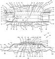
- the wound bedmay include undermined flaps, sinuses, tunnels, and fistulae and the surrounding affected tissues.
- An example of a complex wound bed including some reference anatomyis illustrated in FIG. 1 .
- Wound boundaryrefers to the perimeter of the wound bed at the skin surface of the skin.
- Woundsmay take a long time to heal, for example, due to compromised circulation and hypoxia.
- a 2012 study based on the US Wound Registryanalyzed reimbursement data on 5240 patients with 7099 wounds and determined the cost to treat 6.4 million wounds in the US to be a shocking $50 billion, more than twice the previous estimate and an expense that is 10 ⁇ the budget of the WHO. 65.8% of wounds have an average healing time of 15 weeks and 10% of wounds taking 33 weeks or more to heal. Nearly 80,000 amputations occur annually in the US, and each amputation may represent many months, if not years, of failed costly therapy.
- NGWT devicesmay include a dressing packed into the wound bed, a thin flexible sheet of generally fluid-impervious polymer that is adhesive coated on its underside, and an evacuation tube in fluid communication with the dressing. While the sheet in common clinical use is often referred to as “occlusive” or even “semi-permeable”, it is understood that its permeability is generally limited to transpiration (allowing the skin to ‘breathe’) and not ready passage of fluids.
- the dressingmay be, for example, cotton gauze, or open-cell foam made from polyvinyl alcohol or polyurethane.
- the sheetmay be then centered over the dressing and wound bed, and then secured sealingly adhesively to the skin around the wound bed to seal the wound bed and dressing. Finally, an aperture is created in the sheet over the dressing, and a connector and evacuation tubing is sealingly engaged with that aperture. Air within the region between the sheet and the wound bed is evacuated through the tubing to produce a suction pressure p s within the region that is less than the ambient pressure p amb . The wound bed and surrounding skin contract as the pressure within the region is decreased by suction pressure p s which causes ambient pressure to compresses the sheet and dressing upon the wound bed. Exudate from the wound bed may be drawn through the dressing and evacuated through the evacuation tube.
- the dressingmust be trimmed to the exact geometry of wound bed as overlap of the dressing over normal skin may result in maceration of the normal skin. Undetected dressing fragments and trimming debris in the wound may create foci for infection.
- the dressingmay require frequent changing, typically every other day, and each dressing change may be excruciating, so painful that a strong analgesic or local anesthetic may be required as premedication prior to the dressing change. Desirable granulation tissue may be drawn by suction pressure p s into the micro-crevices of the dressing, which is in constant contact with the wound bed, and the granulation tissue may be torn or damaged with each dressing change resulting in recurring setbacks in the healing process.
- dressing changesare costly in terms of time, medical personnel and consumables.
- the suction pressure p s over the wound bedmay be uneven as the suction pressure p s is transmitted through varying dressing thicknesses across varying distances from the evacuation tube.
- This uneven suction pressure distribution, as well as the uneven compression pressure from the same thickness dressing being forced into an uneven thickness wound bedmay be important in the causation of well-documented diminished blood flow in the wound bed near the wound boundary of the wound bed.
- Such diminished blood flow within the wound boundarymay impede healing of the wound bed because healing typically diminishes the wound bed from the periphery towards the center.
- healingtypically diminishes the wound bed from the periphery towards the center.
- current NPWT devicesmay not be able to increase blood flow sufficiently because the suction pressure p s compresses the capillaries in the wound bed, which works at cross purposes to the goal of increasing blood flow.
- Drainage of the wound bedmay also be problematic in current NPWT devices as the protein-rich exudate from the wound bed may be retained in the dressing and evacuation tube, often resulting in clogging of the suction system, false pressure readings and unrecognized cessation of NPWT therapy.
- current NPWT devicesmay only be used after a wound is first cleaned and debrided, and also may not be usable during the terminal phase of wound healing, as the presence of the dressing, which acts as a foreign body in the wound bed, may prevent full closure of the wound bed.
- the wound therapy apparatusmay include a wound interface sealingly securable to the skin surface around a wound bed to encloses a wound boundary of a wound bed within an enclosed space formed by the wound interface that is fluid-tight.
- the wound interfacemay be sufficiently deformation resistant to distend at least a portion of the wound bed into the enclosed space when pressure p 0 within the enclosed space is less than ambient pressure p amb .
- the wound therapy apparatusmay include a port disposed about the wound interface to communicate fluid with the enclosed space when the wound interface is sealingly secured to the skin surface in order to vary the pressure p 0 within the enclosed space periodically over the pressure range p min ⁇ p 0 ⁇ p max , in various aspects.
- the wound therapy apparatusmay include a pad receivable within the enclosed space to absorb exudate emanating from the wound bed, in various aspects.
- the variation of the pressure p 0distends the wound bed into communication with the pad received within the enclosed space and releases the wound bed from communication with the pad received in the enclosed space when the wound interface is sealingly secured to the skin surface around the wound bed, in various aspects.
- Related methods of use of the wound therapy apparatusare also disclosed herein.
- FIG. 1by cross-sectional view an exemplary wound bed that has undermining, wound tunneling, and fistulae;
- FIG. 2 Aillustrates by cross-sectional view an exemplary implementation of a wound therapy apparatus
- FIG. 2 Billustrates by magnified cross-sectional view the circled area of the exemplary implementation of the wound therapy apparatus illustrated in FIG. 2 A ;
- FIG. 3illustrates by perspective view a second exemplary implementation of a wound therapy apparatus
- FIG. 4 Aillustrates by perspective view portions of the exemplary wound therapy apparatus of FIG. 3 ;
- FIG. 4 Billustrates by exploded perspective view portions of the exemplary wound therapy apparatus of FIG. 3 ;
- FIG. 5 Aillustrates by cross-sectional view portions of the exemplary wound therapy apparatus of FIG. 3 at an exemplary first stage of operation
- FIG. 5 Billustrates by cross-sectional view portions of the exemplary wound therapy apparatus of FIG. 3 at an exemplary second stage of operation
- FIG. 6illustrates by perspective view a third exemplary implementation of a wound therapy apparatus
- FIG. 7 Aillustrates by cross-sectional view portions of the exemplary wound therapy apparatus of FIG. 6 at an exemplary first stage of operation
- FIG. 7 Billustrates by cross-sectional view portions of the exemplary wound therapy apparatus of FIG. 6 at an exemplary second stage of operation
- FIG. 8illustrates by cross-sectional view portions of a fourth exemplary implementation of a wound therapy apparatus
- FIG. 9illustrates by cross-sectional view portions of a fifth exemplary implementation of a wound therapy apparatus
- FIG. 10illustrates by cross-sectional view portions of a sixth exemplary implementation of a wound therapy apparatus
- FIG. 11 Aillustrates by cross-sectional view portions of a seventh exemplary implementation of a wound therapy apparatus in a first stage of operation
- FIG. 11 Billustrates by cross-sectional view portions of the exemplary implementation of a wound therapy apparatus of FIG. 11 A in a second stage of operation;
- FIG. 12illustrates by cross-sectional view portions of an eighth exemplary implementation of a wound therapy apparatus
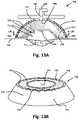
- FIG. 13 Aillustrates by cross-sectional view portions of a ninth exemplary implementation of a wound therapy apparatus
- FIG. 13 Billustrates by cross-sectional perspective view portions of the exemplary implementation of the wound therapy apparatus of FIG. 13 A ;
- FIG. 14illustrates by schematic diagram a tenth exemplary implementation of a wound therapy apparatus.
- FIG. 15illustrates by process flow chart an exemplary method of use of the wound therapy apparatus.
- the wound therapy apparatusincludes a wound interface sealingly securable to the skin surface around a wound bed to enclose portions of the wound bed at the skin surface by an enclosed space defined within the wound interface that is fluid-tight.
- the wound interfaceis sufficiently deformation resistant to accommodate distention of at least a portion of the wound bed into the enclosed space when the pressure p 0 within the enclosed space is less than ambient pressure p amb , in various aspects.
- the wound interfacemay be functionally connected to other devices ranging from a manual suction source to a control module that monitors various parameters within the enclosed space and interacts with such parameters to deliver various therapies to the wound bed.
- the wound therapy apparatusmay include one or more ports that fluidly communicate with the enclosed space to periodically vary the pressure p 0 within the enclosed space over a pressure range p min ⁇ p 0 ⁇ p max by flowing gaseous fluids into or out of the enclosed space through the one or more ports provided for that purpose.
- the time period over which the pressure p 0 is periodically variedmay range from about 5 minutes (12 times per hour) to about 6 minutes (10 times per hour), in various aspects, or may be shorter or longer.
- Periodically varying the pressure p 0 within the enclosed spacemay massage the wound bed and surrounding tissue, for example, by alternately distending the wound bed into the enclosed space by suction pressure p 0 ⁇ p amb and releasing the wound bed from distention into the enclosed space to baseline state at p 0 ⁇ p amb .
- Exudateincludes, for example, proteinaceous liquids exuded from the wound bed, along with various plasma and blood components. Exudate may also include other liquids used in treating the wound bed.
- Fluidincludes, liquid(s), gas(ses), and combinations thereof.
- Liquidmay include, for example, saline solution, proteolytic enzyme solutions, antimicrobial lavages, amniotic fluid, and exudate.
- Gasmay include, for example, air, oxygen, nitric oxide, nitrogen, therapeutic or inert gasses, and combinations thereof.
- fluid-tight or related termsmeans sufficiently leak-resistant to allow insufflation or vacuum suction to create pressure p 0 within the enclosed space that may be above or below ambient pressure p amb .
- fluid-tightmeans sufficiently leak-resistant to substantially retain fluids including both gasses and liquids within the enclosed space other than by controlled fluid communication through one or more lumen that fluidly communicate through the wound interface with the enclosed space, in certain aspects.
- fluid tightmeans sufficiently leak-resistant to maintain pressure p 0 within the enclosed space that may be above or below ambient pressure p amb .
- Ambient pressure p ambrefers to the pressure in a region surrounding the wound therapy apparatus.
- Ambient pressure p ambmay refer to atmospheric pressure, hull pressure within an aircraft or submarine where the wound therapy apparatus is being utilized, or pressure maintained generally within a building or other structure where the wound therapy apparatus is being utilized.
- Ambient pressure p ambmay vary, for example, with elevation or weather conditions.
- Pressure p minrefers to the minimum pressure achieved within the enclosed space of the wound therapy apparatus, and periodically varying of pressure p 0 , pressure variation, varying pressure, and similar term refer to changes of pressure p 0 within the enclosed space over time.
- Pressure p maxrefers to the maximum pressure achieved within the enclosed space of the wound therapy apparatus.
- Padmay include a range of absorbent materials that absorb exudate including open-cell foam composed, for example, of polyvinyl alcohol (PVA), polyurethane or other polymer foam.
- the padmay include various fibers such as sodium carboxymethyl cellulose hydrofiber (Aquacel®), or a nonwoven fabric comprised of multi-component fibers of nylon and polyester that have been longitudinally split into their individual components by hydroentanglement (Evolon®).
- the padmay include knitted fibers, such as in the jersey-knit pattern with hydrophobic fibers predominant on outer surface and hydrophilic fibers predominantly on the inside to serve as a conduit to fluid transfer.
- the padmay also include non-knitted fibers that have been co-wound, cross-laid and/or twisted together into suitable shapes, such as cylinders or ribbons of various sizes and thicknesses, wherein numerous linear passageways are created between fibers to conduct liquid by capillary action.
- the hydrophobic fibermay be formed of a polyester, and the hydrophilic fiber may be formed of aliphatic polyamide fiber or semi-aromatic polyamide fiber (e.g. Nylon®).
- a polyester-polyurethane copolymer fibere.g. Spandex® or Lycra®
- the hydrophobic fibersmay wick away liquid to prevent moisture buildup and, thus, maceration of tissue with which it is in contact.
- the hydrophilic fibersmay promote wicking to help transmit the fluid towards the evacuation port of the wound interface.
- a wound interface that is deformation resistantmaintains an enclosed space within sufficient to draw wound tissue towards the enclosed space, up to occupying the enclosed space, when subjected to pressure p 0 ⁇ p amb , in various aspects.
- the wound interfaceis sufficiently deformation resistant to maintain the enclosed space resulting in distention of at least a portion of the wound bed towards or into the enclosed space by a pressure p 0 within the enclosed space that is less than ambient pressure p amb .
- the wound interfaceis sufficiently deformation resistant to maintain the enclosed space over the wound bed, resulting in distention of at least a portion of the wound bed towards the enclosed space or into the enclosed space by a pressure p 0 within the enclosed space sufficiently below ambient pressure p amb .
- at least portions of the wound interface that define the enclosed spacemay be essentially rigid.
- the wound interfacein various aspects, is sufficiently deformation resistant to remain sealingly secured to skin and fluid-tight over pressure range p min ⁇ p 0 ⁇ p max .
- distal and proximalare defined from the point of view of a healthcare provider, treating a patient with the wound therapy apparatus.
- a distal portion of the wound therapy apparatusis oriented toward the patient and a proximal portion of the wound therapy apparatus is oriented toward the physician.
- a distal portion of a structureis the portion closest to the patient while a proximal portion of the structure may be the portion closest to the physician.
- Massaging of the wound bed via pressure variationsmay be accompanied by fluxes of increased blood flow.
- the terms massage, massaging, rhythmic distortion, tissue deformation, distention of wound bedmay be used interchangeably in this disclosure to refer to the general process of subjecting the wound bed to pressure fluctuations and the resultant changes in the wound bed, including blood flow, oxygenation, cellular tension, macro- and micro-deformation and other changes.
- the surges of increased blood flow proximate the wound bedmay bring increased nutrients and immunity elements, reduce infection and inflammation, and confer other beneficial effects that may promote healing of the wound bed.
- Massaging of the wound bedmay promote the removal of exudate from the interstitial space of the wound bed to exit the wound crater.
- At least one of the one or more portsmay fluidly communicate with the pad to allow transfer of exudate from the pad.
- at least one of the one or more portsmay be fluidly used for monitoring directly or indirectly parameters within the enclosed space such as pressure, temperature, humidity, pH, tissue oxygenation level, blood flow, etc. to effect improved therapy.
- FIGS. 2 A and 2 Billustrates exemplary wound therapy apparatus 1000 .
- wound therapy apparatusincludes wound interface 1015 secured to the skin surface 1011 to enclose wound bed 1013 within enclosed space 1017 defined by wound interface 1015 .
- wound interface 1015includes cover 1002 , which may have a range of transparency ranging from clear to opaque, an annular base flange 1004 , and one or more ports, such as port 1003 emanating from the wound interface.
- the port(s)are optional, in this implementation, such as for wound protection and humidification.
- Port 1003fluidly communicates with enclosed space 1017 , as illustrated, and may be connected to tubing in communication with various fluid sources or fluid sinks for fluid communication between the fluid sources or fluid sinks and enclosed space 1017 .
- Port 1003may be used for monitoring directly or indirectly parameters within enclosed space 1017 .
- Port 1003may be connected to a source such as a suction squeeze bulb 1034 illustrated in FIG. 2 A in order to provide intermittent NPWT.
- Squeeze bulb 1034may have one-way valves 1032 a , 1032 b to ensure unidirectional suction evacuation of the enclosed space.
- An optional relief valve 1030may be incorporated into the wound interface 1015 or interposed between port 1003 and the bulb 1034 in order to limit the lowest suction pressure within the enclosed space.
- Port 1003may be sealably open or closed by a variety of mechanism, including a self-sealing one-way valve 1032 a as may be frequently used in medical applications.
- the suction bulb 1034can similarly be equipped with a coupling tip to couple with valve 1032 a to provide intermittent suction therapy such as may be needed in remote military missions or rural health settings.
- the base flange 1004is designed to be flexible, conformable, and pressure defusing diffusing, in this implementation. This may be achieved singularly or in combination in a variety of ways including base flange 1004 having a reduced thickness compared to the rest of the wound interface 1015 , by molding or co-molding with a softer polymer, and/or by suitable structural modification to permit enhanced stretch and flexibility either diffusely or by sector.
- FIG. 2 Billustrates one implementation of this enhanced flexibility in which a living hinge 1020 is molded around the perimeter of base flange 1004 .
- a living hinge 1020is molded around the perimeter of base flange 1004 .
- the base flange 1004may be directly secured to skin 1011 by adhesive, one implementation interposes between the base flange and skin, an optional annular cushion 1005 that may take the form of closed cell foam 1012 a (as shown on the left side of FIG. 2 A ) or an air sac 1012 b (as shown on the right side of FIG. 2 A ).
- annular apron 1007 of suitable bandage material such as polyurethane with an undercoating of adhesive 1008is adhered proximally to the base flange, and adhered distally to the skin to anchor the wound interface sealingly against skin 1011 .
- a padsuch as pad 50 , 150 , 450 , 550 , 650 , may optionally be disposed in communication with the enclosed space 1017 to absorb exudate emanating from the wound bed, in various aspects.
- Cover 1002forms a raised wound interface having a generally circular, rectangular or ovoid footprint, with a base flange 1004 that extends around the entire perimeter of cover 1002 .
- Wound interface 1015is sealed to skin surface 1011 by base flange 1004 , and additionally but optionally cushion 1005 and adhesive 1006 or apron 1007 and adhesive 1006 .
- Wound interface 1015is essentially fluid-tight, as illustrated, and enclosed space 1017 completely encloses wound bed 1013 .
- Interior pressure p 0may be established by input or withdrawal of fluid into enclosed space 1017 or evacuation of fluid from enclosed space 1017 via port 1003 .
- Pressure p 0may be varied periodically generally over the pressure range p min ⁇ p 0 ⁇ p amb to periodically distend the wound bed 1013 into enclosed space 1017 and to release wound bed to a baseline state upon reduction or release of suction.
- Wound interface 1015may be sufficiently deformation resistant to accommodate distention of at least a portion of the wound bed into the enclosed space 1017 when the pressure p 0 within the enclosed space is sufficiently below ambient pressure p amb .
- wound interface 1015maintains concavity 1025 of enclosed space 1017 oriented toward wound bed 1013 at pressures p 0 ⁇ p amb to allow for distention of at least portions of the wound bed 1013 into enclosed space 1017 .
- FIGS. 3 , 4 A, 4 B, 5 A, and 5 Billustrated exemplary wound therapy apparatus 10 .
- exemplary wound therapy apparatus 10includes wound interface 15
- wound interface 15includes base 20 , cushion 30 , and cover 40 , with cushion 30 secured circumferentially about the perimeter of base 20 to enclose the perimeter of base 20 , and cover 40 secured hingedly to base 20 .
- Base 20as illustrated, has an annular shape, and base 20 defines outer surface 21 and inner surface 23 .
- Cushion 30is annular shaped with footprint corresponding to that of base 20 (see FIG. 5 A ), and cushion 30 defines outer surface 31 and inner surface 33 , as illustrated.
- Distal surface 32 of cushion 30(surface of cushion 30 oriented toward patient) is secured circumferentially sealingly to the skin surface 11 via adhesive layer 90 , as illustrated, and proximal surface 34 of cushion 30 (surface of cushion 30 oriented toward physician) is secured sealingly to distal surface 22 of base 20 around the circumference of base 20 .
- Cushion 30cushions the wound interface 15 against the skin surface 11 , and sealingly conforms to a contour of the skin surface, in this implementation.
- Outer surface 21is generally aligned with outer surface 31 , in this implementation, around the entire perimeter of base 20 and cushion 30 .
- Cover 40is hingedly attached to base 20 by hinge 45 that allows cover 40 to be positionable between open position 46 , illustrated in FIG. 3 , and closed position 48 , illustrated in FIGS. 5 A and 5 B , to disengage or to engage sealingly, respectively, cover 40 with proximal surface 24 of base 20 .
- Hinge 45may be configured to releaseably engage cover 40 with base 20 to allow cover 40 to be replaced with, for example, a fresh cover, a non-see-through cover, or to a cover with differing functionality such as cover 140 of wound therapy apparatus 100 (see FIGS. 6 , 7 A, 7 B ).
- Hinge 45may be, for example, a living hinge, pinned hinge, a snap-fit disengageable coupling, or other hinge, as would be understood by one of ordinary skill in the art upon study of this disclosure.
- Cover 40may be engaged with base 20 by various other mechanisms such as a threaded engagement, or frictional engagement, in other implementations, that allow cover 40 to be sealingly engaged with base 20 and allow cover 40 to be disengaged from base 20 .
- Cover 40may be removably or nonremovably engaged with base 20 , in various implementations.
- Various seals, compression fittings, and so forthmay be provided about cover 40 , base 20 , or cover 40 and base 20 to sealingly engage cover 40 with base 20 .
- hinge 45is optional, and may be omitted in certain implementations, for example, when no direct intervention to the wound bed 13 is contemplated, as in, for example, exemplary wound therapy apparatus 100 illustrated in FIGS. 6 , 7 A, and 7 B .
- an enclosed space 17may be defined by inner surface 43 of cover 40 , inner surface 23 of base 20 , and inner surface 33 of cushion 30 , in this implementation, and enclosed space 17 is essentially fluid-tight when wound interface 15 is secured to skin surface 11 .
- wound interface 15is illustrated as cylindrical in shape enclosing a circular region of skin surface 11 , it should be understood the wound interface, such as wound interface 15 , may assume other geometric shapes such as rectangular, polygonal, or ovoid, to enclose various shaped wounds or regions over skin surface 11 , in various other implementations.
- the wound interfacemay be ovoid shaped and low profile to enclose a linear incision such as from a Caesarian section.
- the wound interfacemay be ovoid and higher profile to enclose the breasts following breast augmentation, or reconstructive breast surgery following mastectomy.
- the term “annular” as used in this disclosureis intended to include other geometric shapes, such as, for example, polygonal, rectangular, or ovoid, with a circumference surrounding a cavity.
- Port 42 and second port 44are disposed about cover 40 , as illustrated, to fluidly communicate with enclosed space 17 between outer surface 41 and inner surface 43 in order that enclosed space 17 may be in fluid communication via port 42 and second port 44 with, for example, fluid reservoir(s), fluid sources, fluid sinks, pump(s), controls, a control module such as control module 880 (see FIG. 14 ), and sensors external to outer surface 41 via tubing including hoses, pipes, valves, and various other fluid conveyances and fittings that may cooperate with port 42 and second port 44 .
- Port 42 and second port 44may fluidly communicate with, for example, a compressed mechanical elastomeric bulb, a re-expanding enclosed space that is powered by various spring-like mechanisms, a mechanical or electrical pump, or a pump in combination with additional elements such as one or more sensors, valves, control module, electronic circuitry, tubing, processor and software that may cooperate to deliver fluids and therapies to the enclosed space 17 or withdraw fluids from enclosed space 17 .
- Port 42is centrally located and second port 44 is located peripherally, in this implementation, but port 42 and second port 44 may be variously located about wound interface 15 , with reciprocal or varied flow directions in various other implementations.
- Input fluid 78may be input into enclosed space 17 via port 44 , and output fluid 76 , which may include exudate 18 (see FIGS. 5 A & 5 B ), may be withdrawn from enclosed space 17 via port 42 (see FIGS. 5 A and 5 B ) or with fluid flow in reverse direction.
- detentssuch as detents 49 a , 49 b disposed circumferentially around a perimeter of cover 40 mechanically cooperate with corresponding base detents, 29 a , 29 b , disposed circumferentially around a rotatable locking ring 27 to releasably retain cover 40 in closed position 48 against base 20 so that enclosed space 17 is fluid-tight.
- Locking ring 27is disposed beneath the surface 21 of base 20 , as illustrated, and locks or releases cover by rotation or sliding in certain directions, in this implementation.
- Various numbers of inter-engaging detents between the cover and base 20such as detents 49 a , 49 b and base detents 29 a , 29 b , and their functional equivalents may be provided in various implementations, and may have various shapes, sizes, mechanisms of operation, and so forth, as would be readily understood by those of ordinary skill in the art upon study of this disclosure.
- face seals, radial seals, compression seals, with and without O-ring or gaskets, and other sealsmay be employed to form a fluid tight seal between the cover and base, as would be readily understood by those of ordinary skill in the art upon study of this disclosure.
- Cushion 30in this implementation, defines cushion chamber 37 (see FIGS. 5 A & 5 B ).
- Cushion 30is formed, for example, of rubber or a polymer such as PVC or silicone.
- An optional cushion port 35extends forth from outer surface 31 of cushion 30 for fluid communication with cushion chamber 37 through cushion port 35 .
- Fluid, including air or other gasses or liquids, within cushion chamber 37 of cushion 30may be regulated via cushion port 35 to provide the desired level of cushioning and sealing of wound interface 15 with respect to skin surface 11 .
- cushion 30may be formed, for example, of various compressible, conformable, fluid-impervious closed cell foams.
- base 20may be formed, for example, of one or more medical polymers including, for example, ABS, polystyrene or polypropylene.
- Cover 40may be transparent, at least in part, to allow visual inspection of enclosed space 17 including wound bed 13 and portions of skin surface 11 enclosed within enclosed space 17 .
- Cover 40may be formed, for example, from polycarbonate, acrylic or other clear polymer material such as copolyester available as Eastman TritanTM available from Eastman Chemical Co.
- FIG. 3illustrates pad 50 disposed within enclosed space 17 of wound therapy apparatus 10 .
- Pad 50in this implementation, is cylindrical in shape and generally annular to leave portions of enclosed space 17 , particularly the space just above the wound bed, unoccupied by pad 50 at least during a certain phase of the therapy such that pad 50 is not in continuous contact with wound bed.
- Outer surface 51 of pad 50may be biased against at least portions of inner surface 33 of cushion 30 , at least portions of inner surface 23 of base 20 , or at least portions of inner surface 43 of cover 40 with cover 40 in closed position 48 , in this implementation.
- pad 50may be used during the initial exudative phase of wound therapy and is removably received within enclosed space 17 to allow periodic removal and replacement of pad 50 when cover 40 is in open position 46 .
- pad 50is secured fixedly to wound interface 15 within enclosed space 17 , in which case replacement of pad 50 includes replacement of both pad 50 and at least the portions of wound interface 15 , such as a detachable and replaceable cover 40 , to which pad 50 is fixedly secured.
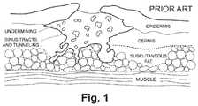
- FIGS. 4 A and 4 Billustrate pad 50 of wound therapy apparatus 10 .
- pad 50is formed of pad components 60 , 70 , 80 that are die-cut slices of stock thickness of, for example, absorbent foam.
- Pad components 60 , 70 , 80 stackably received with one anothermay be stitched together or focally glued together in a manner that does not impeded fluid flow through pad 50 .
- distal surfaces 62 , 72are biased against proximal surfaces 74 , 84 , respectively, as illustrated.
- proximal surface 64 of pad component 60forms proximal surface 54 of pad 50
- distal surface 82 of pad component 80forms distal surface 52 of pad 50
- inner surfaces 63 , 73 , 83form inner surface 53 of pad 50
- outer surfaces 61 , 71 , 81form outer surface 51 of pad 50 , in this implementation.
- Pad 50may include various numbers of pad components, such as pad components 60 , 70 , 80 , and the number of pad components, such as pad components 60 , 70 , 80 , that form pad 50 may be chosen to result in a selected desired thickness of pad 50 .
- An optional loop of polymer threadmay be provided about pad 50 for removal of pad 50 from enclosed space 17 .
- pad 50may be formed as a unitary structure of preselected dimensions.
- pad 50absorbs exudate and functions as a conduit for passage of exudate 18 out of enclosed space 17 via port 42 ( FIG. 5 B ).
- Pad components 60 , 70 , 80may be formed either of the same material or from different materials in different spatial relationships, such as layers or columns, to form differential fluid flow paths or wicking characteristics, if desired.
- Pad component 60in various implementations, may have at least one diagonal, instead of a cross-member, such as cross-member 65 , 67 , or pad component 60 may have three or more cross-members instead of the two cross-members in the illustrated implementation.
- pad component 60may be formed as a continuous structure from outer surface 51 to axis 69 , in which case the annular region within pad component 60 is omitted.
- Various implementations of pad 50may include a single unitary molded or woven structure of selected dimensions.
- Pad components 70 , 80are annular in configuration, in the FIG. 4 B implementation.
- Pad component 60is annular and includes at least one cross member, such as cross-member 65 , 67 , that emanates from inner surface 63 of pad component 60 and passes through axis 69 of the annulus, as illustrated.
- Cross-members 65 , 67intersect one another proximate axis 69 to form central portion 68 , that communicates fluidly with port 42 , which is correspondingly positioned on cover 40 to fluidly communicate with central portion 68 of pad 50 when cover 40 is in closed position 48 .
- absorptive pad 50While various designs of absorptive pad 50 may be feasible for exudate withdrawal out of enclosed space 17 , peripheral portions of pad 50 lead towards that central portion 68 of pad 50 that contacts port 42 in the illustrated implementation. Exudate 18 may be transmitted through pad 50 to central portion 68 and then be withdrawn from pad 50 through port 42 . As illustrated in FIG. 4 A , output fluid 76 and input fluid 78 may pass, at least in part, through aperture 58 of pad 50 , to communicate with enclosed space 17 or wound bed 13 .
- FIGS. 5 A and 5 Bfurther illustrate cross-section views of wound therapy apparatus 10 along axis 5 - 5 of FIG. 3 , with FIG. 5 A illustrating wound therapy apparatus 10 at an exemplary first stage of operation 14 and FIG. 5 B illustrating wound therapy apparatus 10 at an exemplary second stage of operation 16 .
- Wound interface 15is sealingly secured to the skin surface 11 to enclose wound boundary 12 such that portions of wound bed 13 at skin surface 11 are enclosed by enclosed space 17 , which is fluid-tight, as illustrated in FIGS. 5 A and 5 B .
- At least portions of wound bed 13 disposed below skin surface 11such as undermining, sinus tracts, and tunnels (see FIG. 1 ) may be in fluid communication with enclosed space 17 . Note that it may be possible for wound boundary 12 to be enclosed within enclosed space 17 while undermined areas may extend beneath the skin surface 11 beyond enclosed space 17 .
- Adhesive layer 90secures distal surface 32 of cushion 30 to the skin surface 11 , as illustrated on the left side of FIG. 5 A , and adhesive layer 90 is interposed between distal surface 32 of cushion 30 and skin surface 11 .
- Adhesive layer 90may optionally extend over portions of skin surface 11 to include all skin surface under and proximate to the footprint of wound interface 15 , as illustrated on the right side of FIG. 5 A .
- adhesive 90is a medically suitable member of the cyanoacrylate class, such as N-butyl-2-cyanoacrylate (Histoacryl Blue), or octyl-2-cyanoacrylate (Dermabond), the layer of water-resistant adhesive coating over the peri-wound skin surface function to protect normal skin from maceration, secondary to prolonged exposure to liquids.
- Adhesive 90may be, for example, acrylic, silicone or hydrocolloid.
- Other securement mechanismssuch as straps with hook-and-loop-type fasteners may also be employed in various other implementations to secure, at least in part, wound interface 15 to the skin surface 11 .
- Dressingmay be omitted from wound bed 13 , so that no dressing is in contact with the wound bed 13 for much of the duration of wound therapy, which allows for direct assessment of the wound condition through transparent portions of cover 40 , in various implementations.
- pad 50may be in intermittent contact with the wound bed 13 during certain stages of operation. Even in such implementations, at least a portion of the wound bed may be visible either directly through transparent portions of cover 40 and corresponding apertures 58 in pad 50 .
- the absence of the dressing in constant contact with the wound bed 13may avoid the problem of painful tearing of granulation tissue during dressing change with concomitant interruption of the healing process.
- the wound interface 15may need changing only once a week, resulting in savings of healthcare provider time.
- the wound therapy apparatus 10may be employed from initial treatment until complete healing of the wound bed 13 is achieved.
- the wound therapy apparatus 10may support a wide range of therapies, for example, proteolytic enzyme soaks, medical maggot debridement, antibiotic lavage and incubation of tissue stroma, skin grafts, and stem cells, etc.
- wound bed 13 and skin surface 11 within enclosed space 17are in a baseline state 93 with wound bed 13 in spaced relation with distal side 62 of pad component 60 of pad 50 , as illustrated in FIG. 5 A , so that wound bed 13 does not directly contact pad 50 particularly distal side 62 of pad component 60 .
- wound interface 15defines entry 26 to enclosed space 17 , as illustrated, and the portions of wound bed 13 enclosed within wound interface 15 may generally lie outside (e.g. are not drawn upwards through) entry 26 in baseline state 93 .
- Capillary 96which is proximate wound bed 13 , is in a baseline undilated state 98 and conveys a baseline quantity of blood to wound bed 13 , as illustrated.
- pressure p 0p min with p min ⁇ p amb within enclosed space 17 due to withdrawal of output fluid 76 , which may include air and other gasses and liquids as well as exudate 18 , from enclosed space 17 through port 42 .
- Pressure p 0min within enclosed space 17 distends at least portions of the wound bed 13 through entry 26 into the enclosed space 17 so that wound bed 13 is in distended state 94 , as illustrated in FIG. 5 B .
- capillary blood vessels 96including capillaries, arterioles and venules proximate the wound bed, such as capillary 96 , may be in a dilated state 99 .
- capillariesmay be engorged and blood flow about the wound bed 13 may be increased above baseline, with associated salutary benefits.
- distention including deformation and stretching of tissues surrounding the wound bedhas been found to stimulate fibroblast differentiation and wound healing (cf. Saxena, V. et. al., Vacuum Assisted Closure: Microdeformation of Wound and Cell Proliferation . Amer. Soc. Plastic Surg. 1086-1096, October 2004).
- portions of wound bed 13 , skin surface 11 , or portions of wound bed 13 and skin surface 11may bias against at least portions of pad 50 , such as against portions of distal surface 62 of pad component 60 , as illustrated in FIG. 5 B .
- portions of wound bed 13 , skin surface 11 , or portions of wound bed 13 and skin surface 11may bias against inner surface 53 of pad 50 .
- Pressure p minmay be selected to cause distended state 94 with biased engagement between pad 50 and at least portions of wound bed 13 .
- Pad 50absorbs exudate 18 (indicated by the solid black arrows in FIG. 5 B ) from wound bed 13 by biased engagement between pad 50 and wound bed 13 .
- Pad component 80 of pad 50 that surrounds wound bed 13 and contacts skin surface 11may absorb exudate 18 from peri-wound areas within enclosed space 17 . Therefore, in various orientations of wound interface 15 , exudate 18 may be absorbed by at least portions of pad 50 and then evacuated from pad 50 by suction through port 42 . Following absorption by pad 50 , exudate 18 may be transmitted through pad 50 by a combination of capillary action and suction gradient to central portion 68 , and the exudate 18 is then withdrawn from pad 50 at central portion 68 through port 42 , which is in biased engagement with central portion 68 , thereby withdrawing the exudate 18 from enclosed space 17 .
- output fluid 76 withdrawn from enclosed space 17may include gaseous fluids or other liquids within enclosed space 17 along with exudate 18 in order to decrease pressure p 0 within enclosed space 17 .
- Wound therapy apparatus 10may be varied periodically between first stage of operation 14 and second stage of operation 16 by varying pressure p 0 within enclosed space 17 periodically generally over the pressure range p min ⁇ p 0 ⁇ p amb where p min is the minimum pressure over a periodic pressure variation.
- Pressure p 0may be varied by input of input fluid 78 into enclosed space 17 and withdrawal of output fluid 76 from enclosed space 17
- a control modulesuch as control module 880 of wound therapy apparatus 800 (see FIG. 14 ) may be operably connected to wound interface 15 to input the input fluid 78 into enclosed space 17 and to withdraw output fluid 76 from enclosed space 17 .
- the minimum pressuremay be, for example, p min ⁇ p amb ⁇ 150 mm Hg.
- the minimum pressuremay be, for example, p min ⁇ p amb ⁇ 70 mm Hg.
- the minimum pressuremay be, for example, generally within the pressure range (p amb ⁇ 130 mm Hg) ⁇ p min ⁇ (p amb ⁇ 80 mm Hg).
- the minimum pressure p minmay be generally within the pressure range (p amb ⁇ 90 mm Hg) ⁇ p min ⁇ p amb .
- the periodic variation of the pressure p 0may be generally within the pressure range p min ⁇ p 0 ⁇ p max where p max >p amb .
- p max⁇ (p amb +30 mm Hg).
- p max⁇ p amb .
- p max ⁇ p ambfor example, the maximum pressure p max may range between about ⁇ 5 mm Hg and about ⁇ 20 mm Hg below ambient pressure p amb , in certain implementations.
- wound therapy apparatus 10As wound therapy apparatus 10 is varied from first stage of operation 14 to second stage of operation 16 , the pressure p 0 decreases with p 0 ⁇ p min and wound bed 13 is distended through entry 26 into enclosed space 17 to have distention length 19 in distended state 94 at second stage of operation 16 .
- Wound bed 13is released from tension into baseline state 93 as pressure p 0 increases with p 0 ⁇ p max as wound therapy apparatus 10 is varied from second stage of operation 16 to first stage of operation 14 .
- Wound bed 13 in baseline state 93has essentially no distention length, such as distention length 19 , at first stage of operation 14 .
- the periodic variation of pressure p 0results in transient, intermittent contact between pad 50 and wound bed 13 , in this implementation, so that granulation tissue of wound bed 13 will not have time to grow into pad 50 , and, in turn, will not become torn or disrupted when pad 50 or wound interface 15 including pad 50 is replaced.
- the pressure p 0may be generally constant throughout enclosed space 17 , so that the entirety of wound bed 13 is exposed to pressure p 0 , and, thus, no significant pressure gradient is created about wound bed 13 that may, for example, decrease blood flow proximate the wound boundary 12 .
- pad 50may become distended due to absorbtion of exudate 18 so that pad 50 remains in varying degrees of engagement with wound bed 13 as the pressure p 0 is varied periodically over the pressure range p min ⁇ p 0 ⁇ p max distending the wound bed to increase contact between wound bed 13 and pad 50 or retracting the wound bed 13 thus decreasing contact between wound bed 13 and pad 50 but with the pad 50 always in contact with wound bed 13 .
- Input fluid 78 in the form of gas or gaseous mixturesmay be introduced into enclosed space 17 via second port 44 , to regulate, at least in part, the pressure p 0 within enclosed space 17 or to control the composition of the gaseous fluids within enclosed space 17 .
- wound therapy apparatus 10may be periodically varied between first stage of operation 14 and second stage of operation 16 by introduction of input fluid 78 into enclosed space 17 via second port 44 and evacuation of output fluid 76 from enclosed space 17 via port 42 .
- Input fluid 78 introduced into enclosed space 17 via second port 44 and evacuated from enclosed space 17 through port 42 , or vice versamay enhance the withdrawal of exudate 18 from enclosed space 17 , and may prevent clogging by increasing fluid velocities in fluid pathways through increased flow volume.
- Oxygen supplementationin some instances, is especially important to rescue hypoxic tissue on the verge of death, and to support cellular function such as cell division and collagen synthesis, and input fluid 78 may include gas with an O 2 concentration greater than that of atmospheric air. The added oxygen may inhibit anaerobic bacteria growth.
- the input fluid 78may be a liquid, such as saline, to rinse the wound, enclosed space and evacuation tubing, or other therapeutic fluid including antibiotic rinse, or amniotic fluid for its regeneration stimulating effects.
- FIGS. 6 , 7 A and 7 Billustrate another exemplary implementation of a wound therapy apparatus 100 .
- wound interface 115 of wound therapy apparatus 100includes base 120 , and apron 180 .
- Apron 180is coated on its underside with adhesive 190 , and apron, 180 is annular in shape and disposed about the entire perimeter of base 120 with base 120 occupying portions of the annular region defined by apron 180 , in this implementation.
- a distal perimeter of apron 180is sealingly secured to skin surface 111 by adhesive 190 , in this implementation.
- Apron 180may be sized to provide adhesion sufficient to retain wound interface 115 in attachment to the skin surface 111 .
- Apron 180may be formed of a bandage material such as polyurethane.
- wound interface 115includes port 142 located about wound interface that defines lumen 143 for fluid communication with enclosed space 117 .
- Input fluid 178may be input or output fluid 176 may be withdrawn from enclosed space 117 via lumen 143 of port 142 , as indicated by the arrows in FIG. 6 .
- wound interface 115 of wound therapy apparatus 100includes cushion 130 and apron 180 secured to flange 129 of base 120 .
- Wound interface 115in this implementation, is deformation resistant.
- Flange 129is secured sealingly about the entirety of the perimeter of base 120 , in this implementation, and flange may be pressure-diffusing and conformable to skin surface 111 .
- Flange 129may be made of a medical polymer such as polyethylene terephthalate (PET), polytetrafluoroethylene (PTFE), polypropylene (PP), polyurethanes (PU), and silicones that may be sealingly secured to skin surface 111 by adhesive.
- Cushion 130is optional and may aid in diffusing focal pressure or in providing a fluid-tight seal between wound interface 115 and skin surface 111 .
- cushion 130has an annular shape and cushion 130 is secured circumferentially around the entire perimeter of base 120 .
- Proximal side 134 of cushion 130is secured sealingly to distal side 131 of flange 129 around the entire circumference of base 120 , as illustrated.
- Distal side 132 of cushion 130is biased against skin surface 111 about wound bed 113 to cushion wound therapy apparatus with respect to the skin surface 111 or to conform to the contour of skin surface 111 , as illustrated in FIG. 7 A .
- Cushion 130defines cushion chamber 137 , in this implementation.
- Cushion 130may be omitted in certain implementations, in which case base 120 may be held in biased engagement with the skin surface 111 by apron 180 , by distal side 131 of flange 129 , or by both apron 180 and distal side 131 of flange 129 in cooperation with adhesive layer 190 .
- Base 120may be supported by apron 180 to be in spaced relation with skin surface 111 in implementations that omit cushion 130 .
- Apron 180is secured sealingly to proximal side 133 of flange 129 , and apron 180 is secured sealingly to the skin surface 111 around the entire perimeter of base 120 by adhesive layer 190 so that wound boundary 112 is enclosed by fluid tight enclosed space 117 , as illustrated.
- portions of base 120bifurcate to define interstice 127 , and pad 150 is received within at least portions of interstice 127 .
- Passagessuch as passage 128 a , 128 b , 128 c , are formed in at least portions of distal side 122 of base 120 that allow fluid communication between enclosed space 117 and interstice 127 including pad 150 that is received within interstice 127 , in this implementation.
- Exudate 118 emanating from wound 113may pass through passages, such as passage 128 a , 128 b , 128 c , into interstice 127 to be absorbed by pad 150 .
- Port 142fluidly communicates with interstice 127 including pad 150 via lumen 143 to evacuate output fluid 176 including exudate 118 from pad 150 .
- Output fluid 176may be evacuated from enclosed space 117 through lumen 143 of port 142 as enclosed space 117 fluidly communicates with port 142 through the passages, such as passage 128 a , 128 b , 128 c .
- passagessuch as passage 128 a , 128 b , 128 c .
- Port 142as well as any additional ports may be configured for attachment to tubing for the communication of fluids via tubing with enclosed space 117 through port 142 .
- a control modulesuch as control module 880 of wound therapy apparatus 800 (see FIG. 14 ), may be operably connected to lumen 143 of port 143 to input the input fluid 178 into interstice 127 and enclosed space 117 through lumen 143 or withdraw output fluid 176 including exudate 118 from enclosed space 117 and interstice 127 through lumen 143 .
- Base 120includes one or more window(s), such as windows 139 a , 139 b , 139 c , 139 d , formed of transparent material to allow visual inspection of wound 113 through base 120 and through pad 150 , in this implementation.
- Windows 139 a , 139 b , 139 c , 139 dpass between proximal side 124 and distal side 122 of base 120 including portions of interstice 127 , as illustrated.
- wound bed 113is in a baseline state 193 , and wound bed 113 is in spaced relation with portions of distal side 122 of base 120 including passages, such as passage 128 a , 128 b , 128 c , so that wound bed 113 does not directly contact the passages or pad 150 .
- wound interface 115defines entry 126 to enclosed space 117 , and the portions of wound bed 113 enclosed by enclosed space 117 may generally lie outside entry 126 in baseline state 193 .
- enclosed space 117is evacuated, in part, by withdrawal of output fluid 176 from enclosed space 117 through lumen 143 of port 142 so that the pressure p o within enclosed space 117 is less than ambient pressure p amb (i.e., p 0 ⁇ p amb ), which causes at least portions of wound bed 113 to be distended into enclosed space 117 through entry 126 in distended state 194 with at least portions of wound bed 113 biased against distal side 122 of base 120 including passages, such as passage 128 a , 128 b , 128 c .
- ambient pressure p ambi.e., p 0 ⁇ p amb
- Exudate 118may thus be withdrawn from wound bed 113 through the passages, such as passage 128 a , 128 b , 128 c , into interstice 127 for adsorption by pad 150 at second stage of operation 116 .
- Pad 150fluidly communicates with lumen 143 of port 142 so that exudate 118 may be evacuated from pad 150 through port 142 as at least a portion of output fluid 176 via external suction applied to port 142 .
- Wound therapy apparatus 100may be varied periodically between first stage of operation 114 and second stage of operation 116 by varying pressure p 0 within enclosed space 117 periodically generally over the pressure range p min ⁇ p 0 ⁇ p max to distend wound bed 113 into enclosed space 117 in distended state 194 and to release wound bed 113 from distention into enclosed space 117 back to baseline state 193 , respectively, thereby massaging wound bed 113 .
- pressure p 0within enclosed space 117 periodically generally over the pressure range p min ⁇ p 0 ⁇ p max to distend wound bed 113 into enclosed space 117 in distended state 194 and to release wound bed 113 from distention into enclosed space 117 back to baseline state 193 , respectively, thereby massaging wound bed 113 .
- p min ⁇ p amb and p amb ⁇ p maxin this implementation.
- the pressure p 0may be generally constant throughout enclosed space 117 , so that the entirety of wound bed 113 is exposed to pressure p 0 , that, for example, may result in increased blood flow proximate the wound boundary.
- Periodically releasing wound bed 113 from contact with distal side 122 of base 120may prevent wound bed 113 from becoming attached to distal side 122 of base 120 , passages, such as passage 128 a , 128 b , 128 c , or pad 150 .
- Capillary 196which is proximate wound bed 113 , is in a baseline undilated condition 198 and conveys a baseline quantity of blood to wound bed 113 when wound bed 113 is in baseline state 193 at first stage of operation 114 , as illustrated in FIG. 7 A .
- Capillary vessels proximate the wound bed, such as capillary 196may be in a dilated state 199 when wound bed 113 is in distended state 194 at second stage of operation 116 , as illustrated in FIG. 7 B .
- Input fluid 178may be input into enclosed space 117 via port 142 , as indicated by the arrow in FIG. 6 , for example, to regulate, at least in part, the pressure p 0 within enclosed space 117 , to control the composition of the gaseous fluids within enclosed space 117 , or for various therapeutic purposes.
- wound therapy apparatus 100may be periodically varied between first stage of operation 114 and second stage of operation 116 by consecutive input of input fluid 178 into enclosed space 117 and withdrawal of output fluid 176 from enclosed space 117 via port 142 .
- FIG. 8illustrates exemplary wound therapy apparatus 200 .
- wound therapy apparatus 200includes wound interface 215 that is deformation resistant and defines enclosed space 217 that is fluid-tight when engaged with skin surface 211 to enclose wound bed 213 at skin surface 211 .
- Wound interface 215includes cover 240 slidably sealingly frictionally removably engaged with base 220 .
- Cover 240may include at least transparent portions to allow visual inspection of wound bed 213 though cover 240 .
- Base 220may include flange 209 around an outer perimeter of base 220 that may provide structural support or sealing surface in cooperation with cover 240 , as illustrated. In other implementations, cover 240 and base 220 may be formed as a unitary structure.
- Base 220may include flange 229 around a perimeter of outer side 223 generally at distal end 222 of base 220 with flange 229 secured to skin surface 211 by adhesive 290 , as illustrated in FIG. 8 .
- Flange 229may be designed by thickness and/or polymeric material to be soft and conformable to skin surface 211 to enable sealing of wound interface 215 over a wound 213 in a fluid-tight manner while distributing forces on wound interface 215 from pressure p 0 within enclosed space 217 over the skin surface 211 .
- Port 242which is located about wound interface 215 , is in fluid communication with enclosed space 217 via lumen 243 .
- a padsuch as pad 50 , 150 , 450 , 550 , 650 , 750 (see FIGS. 10 , 11 A, 11 B, 12 and 13 A ), may be deployed within cavity 217 , and the pad may be in fluid communication with lumen 243 of port 242 to allow transfer of exudate from wound bed 213 through the pad and thence through lumen 243 of port 242 .
- One or more additional ports, such as port 244in communication with enclosed space 217 may be situated about the wound interface 215 for monitoring intra-enclosed space parameters within enclosed space 217 , communication of fluids with enclosed space 217 , or other therapeutic interventions with enclosed space 217 .
- port 244may be sealed by valve 299 including but not limited to, for example, plugs, clamps, various stopcocks and solenoid valves.
- FIG. 9illustrates exemplary wound therapy apparatus 300 .
- wound therapy apparatus 300includes wound interface 315
- wound interface 315includes base 320 and cover 340 .
- Base 320is formed to include flange 329 and receptacle 310 .
- Flange 329is an annular structure that extends forth from outer side 323 at distal end 322 of base 320 .
- Flange 329may be formed as a unitary part of base 320 .
- Flange 329may be adhesively attached to skin 311 around wound bed 313 by adhesive 390 , as illustrated in FIG. 9 .
- Cover 340may be inserted into an aperture defined by receptacle 310 , which is fluted to ease insertion, as illustrated in FIG. 9 .
- Stop 309which forms an inward flange, limits insertion of cover 340 into receptacle 310 , and provides additional seal surface between cover and base to form a fluid-tight seal between cover 340 and base 320 so that cavity 317 is fluid-tight, in this implementation.
- a padsuch as pad 50 , 150 , 450 , 550 , 650 , 750 , may optionally be deployed within cavity 317 in fluid communication with lumen 343 of port 342 .
- FIG. 10illustrates portions of exemplary wound therapy apparatus 400 .
- wound interface 415includes cover 440 that defines, in part, enclosed space 417 that encloses wound bed 413 at skin surface 411
- pad 450is attached to inner surface 446 of cover 440 to communicate with lumen 443 of port 442 and to communicate with at least portions of wound bed 413 when the pressure p 0 within enclosed space 417 is reduced thereby causing wound bed 413 to be distended into contact with pad 450 .
- exudatemay be communicated from wound bed 413 into pad 450 and out of enclosed space 417 via lumen 443 of port 442 .
- Lumen 443passes between inner surface 446 and outer surface 448 of cover 440 , as illustrated.
- pad 450is generally a unitary structure with a columnar configuration that extends forth from distal side 446 of cover 440 to be in contact with the wound bed 413 during at least a portion of a periodic pressure variation.
- Length X of pad 450may be less than length Y from distal side 442 of cover 440 to the skin surface 411 or to wound bed 413 .
- FIGS. 11 A and 11 Billustrate exemplary wound therapy apparatus 500 in exemplary stages of operation 505 , 510 , respectively.
- Exemplary wound therapy apparatus 500includes wound interface 515 with inner surface 543 and outer surface 546 with inner surface 543 defining enclosed space 517 .
- Pad 550is disposed within enclosed space 517 , as illustrated, and port 542 forms lumen 549 between interior end 545 and exterior end 547 of port 542 .
- Lumen 549passes through wound interface between inner surface 543 and outer surface 546 for fluid communication with enclosed space 517 .
- output fluid 563in the form of gas is being evacuated from enclosed space 517 through pad 550 and then through lumen 549 from interior end 545 to exterior end 547 , as indicated by a solid arrow in FIG. 11 A .
- the resulting pressure gradientcauses portions of side 551 of pad 550 to bias against interior end 545 of port 542 , as illustrated.
- Exudate 561is drawn through pad 550 and then through lumen 549 from interior end 545 to exterior end 547 .
- output fluid 563may include liquid, gas, or combinations of liquid(s) and gas(ses).
- the pressure p 0 within enclosed spaceis greater than or equal to p amb , and surface 551 of pad 550 is disengaged from interior end 545 of port 542 .
- surface 551 of pad 550alters between biased engagement with interior end 545 of port 542 when fluid is being evacuated from enclosed space 517 through port 542 at first stage of operation 505 , and disengagement from interior end 545 of port 542 when either no fluid is being evacuated from enclosed space 517 or fluid is being input through port 542 at second stage of operation 510 .
- exemplary wound therapy apparatus 600includes wound interface 615 with inner surface 643 and outer surface 646 with inner surface 643 defining enclosed space 617 .
- Pad 650is disposed within enclosed space 617 , as illustrated, and port 642 forms lumen 649 between interior end 645 and exterior end 647 of port 642 .
- Lumen 649passes through wound interface between inner surface 643 and outer surface 646 .
- the pressure p 0 within enclosed spacegenerally equals p amb and no suction is being applied to port 642 to evacuate fluid from enclosed space 617 .
- exemplary wound therapy apparatus 500which is illustrated in FIGS.
- side 651 of pad 650remains biased against interior end 645 of port 642 , as illustrated in FIG. 12 .
- side 651is in biased engagement with interior end 645 of port 642 during evacuation of fluid from enclosed space 617 as well as during cessation of evacuation of fluid from enclosed space 617 through port 642 or even during input of fluid into enclosed space through port 642 .
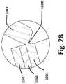
- FIGS. 13 A, 13 Billustrates exemplary wound therapy apparatus 700 .
- enclosed space 717is defined by wound interface 715 of wound therapy apparatus 700
- pad 750is disposed within enclosed space 717 in fluid communication with lumen 743 of port 742 .
- Pad 750as illustrated in FIGS. 13 A, 13 B , is formed as a woven composite of synthetic fibers that may include a hydrophobic fiber 792 , a hydrophilic fiber 790 , and an elastomeric fiber 794 .
- Various knitting weavescan be deployed to hold the fibers 790 , 792 , and 794 together.
- a simple jersey-knitis used to create a bi-layer structure with one layer that is predominantly hydrophilic fiber 790 and the other layer of predominantly hydrophobic fibers 792 .
- This structuremay then be folded upon itself and stitched at the open perimeter to create pad 750 that is predominantly hydrophobic fibers 792 proximate the surface 751 of pad 750 and predominantly hydrophilic fibers 790 within the interior 753 of pad 750 , as illustrated in FIG. 13 B .
- the hydrophobic fibers 792force exudate including other liquids from surface 751 onto the hydrophilic fibers 790 in interior 753 .
- the exudatemay be retained by hydrophilic fibers 790 and transferred through hydrophilic fibers 790 to lumen 743 of port 742 for withdrawal from enclosed space 717 by suction pressure applied to lumen 743 .
- pad 750takes the form of an inverted bowl that is positioned over the wound bed 713 .
- Pad 750may not directly contact the wound bed except during certain stages of operation of wound therapy apparatus 700 when pressure p 0 within enclosed space 717 is sufficiently negative to draw the wound bed into contact with pad 750 .
- exudate from wound bed 713may be transferred from wound bed 713 to pad 750 , through pad 750 , and from pad 750 through port 742 .
- Pad 750may optionally have region 796 that is at least in intermittent contact with port 742 , that does not have, or has very little, hydrophobic fibers 792 at region 796 of surface 751 .
- Pad 750may additionally have different weave content in different regions of pad 750 for specific applications. For example, having a predominantly hydrophobic fiber 792 at a portion of surface 751 will decrease amount of moisture at the surface 751 , and, hence, the likelihood of skin maceration from prolonged wet contact with this portion of surface 751 . Pad 750 may be replaceably and removably deployed in wound interface 715 or pad 750 may be fixedly engaged with wound interface 715 , in various implementations.
- FIG. 14illustrates exemplary wound therapy apparatus 800 .
- wound therapy apparatus 800includes gas source 882 and liquid source 884 in fluid communication with control module 880 , and control module 880 is in fluid communication with wound interface 815 .
- Wound interface 815is secured to skin surface 811 to define enclosed space 817 over a wound bed, such as wound bed 13 , 113 , 213 , 313 , 413 , 713 1013 , as illustrated.
- Wound interface 815may be formed, for example, similarly to wound interface 15 , 115 , 215 , 315 , 415 , 515 , 615 , 715 , 1015 and enclosed space 817 may be similar to enclosed space 17 , 117 , 217 , 317 , 417 , 517 , 617 , 717 , 1017 , respectively.
- Control module 880may monitor various parameters within the enclosed space 817 such as pressure p 0 , and control module 880 may interact with such parameters to deliver various therapies.
- Control module 880in this implementation, includes control group 893 and canister 881 , and control group 893 includes microcontroller 887 in operative communication with power source 898 , user I/O 886 , valve 888 , pump 889 , and pressure sensor 891 to control or monitor the operation of power source 898 , valve 888 , pump 889 , pressure sensor 891 , at least in part in response to the user inputs via user I/O 886 .
- Microcontroller 887may include, for example, a microprocessor, memory, A/D converter, D/A converter, clock, I/O connectors, and so forth, and microcontroller 887 may be configured, for example, as a single chip or as chip set mounted on a board, as would be readily recognized by those of ordinary skill in the art upon study of this disclosure.
- Power source 898may be, for example, mains electric or battery, and power source 898 may include, for example, a transformer, inverter, rectifier, or voltage filter.
- Valve 888 and pressure sensor 891may be representative of various numbers and configurations of valves and various numbers and configurations of pressure sensors, respectively, in this illustration.
- Various communication pathwaysmay be disposed about control module 880 to communicate electrical power from power source 898 to microcontroller 887 , valve 888 , pump 889 , and pressure sensor 891 .
- User I/O 886may include various switches, push buttons, dials, and so forth, whether virtual or physical for obtaining user inputs that are then communicated to microcontroller 887 in order to allow the user to direct the operation of wound therapy apparatus 800 .
- Various communication pathwayssuch as electrical, electromagnetic (e.g. Bluetooth), optical (e.g. LASER, IR), and networked communications may be employed for communication between microcontroller 887 and user I/O 886 .
- Microcontroller 887controls the operation of wound therapy apparatus 800 including control module 880 based, at least in part, upon user inputs communicated to microcontroller 887 from user I/O 886 .
- Microcontroller 887may communicate date to user I/O 886 indicative of the operation of wound therapy apparatus 800 , and user I/O 886 may display this data to the user.
- User I/O 886may be located in proximity to microcontroller 887 , in some implementations, and user I/O 886 may be, at least in part, remotely located from and in network communication with microcontroller 887 .
- gas source 882fluidly communicates gas 883 with control group 893 of control module 880
- liquid source 884fluidly communicates liquid 885 with control group 893 of control module 880
- Control group 893 of control module 880 as controlled by microcontroller 887is operable to select input fluid 846 as gas 883 from gas source 882 , liquid 885 from liquid source 884 , or a combination of gas 883 from gas source 882 and liquid 885 from liquid source 884 .
- Input fluid 846is input into enclosed space 817 as controlled by control group 893 of control module 880 .
- Input fluid 886may be, for example, equivalent to input fluid 78 , 178 .
- Control group 893 of control module 840 as controlled by microcontroller 887is operable to control the flow of input fluid 846 from control module 880 to enclosed space 817 of wound interface 815 , the flow of output fluid 848 from enclosed space 817 of wound interface 815 to control module 880 , and the exhausting of at least portions of output fluid 848 into the ambient environment, in this implementation, using valve 888 , pump 889 , and pressure sensor 891 .
- Output fluid 848may be, for example, equivalent to output fluid 76 , 176 , 563 .
- control module 880may cycle the pressure p 0 within enclosed space 817 , for example, over a pressure range p min ⁇ p 0 ⁇ p max .
- Valve 888may include one or more valves disposed about control module 880 and operable, for example, to select input fluid 846 as either gas 883 from gas source 882 or liquid 885 from liquid source 884 , to control the flow of input fluid 846 from control module 880 into enclosed space 817 of wound interface 815 , and to control the flow of output fluid 848 withdrawn from enclosed space 817 of wound interface 815 to control module 880 .
- Pressure sensor 891may include at least one or more pressure sensors operable, for example, to monitor pressure at various locations in gas 883 , liquid 885 , input fluid 846 , output fluid 848 , or pressure p 0 within enclosed space 817 of wound interface 815 .
- Microcontroller 887may alter the operation of valve 888 or pump 889 in response to signals from pressure sensor 891 .
- Input fluid 846may be communicated under pressure at gas source 882 or liquid source 884 , and pump 889 may be used to convey output fluid 848 from enclosed space 817 through canister 881 for rejection into the ambient environment.
- Wound therapy apparatus 800may include various fluid conveyances, for example hoses, pipes, valves, tubing, connectors, pressure regulators, and various other fittings, to communicate gas 883 and liquid 885 from gas source 882 and liquid source 884 , respectively, to control module 880 and to communicate input fluid 846 and output fluid 848 between enclosed space 817 of wound interface 815 and control module 880 .
- various fluid conveyancesfor example hoses, pipes, valves, tubing, connectors, pressure regulators, and various other fittings, to communicate gas 883 and liquid 885 from gas source 882 and liquid source 884 , respectively, to control module 880 and to communicate input fluid 846 and output fluid 848 between enclosed space 817 of wound interface 815 and control module 880 .
- Output fluid 848passes through canister 881 as output fluid 848 is returned to control module 880 following withdrawal from enclosed space 817 of wound interface 815 , and exudate 819 or liquid, such as liquid 885 , from fluid 848 is captured from output fluid 848 in chamber 899 of canister 881 . Gaseous portions of output fluid 848 or gas displaced from chamber 899 of canister 881 by capture of exudate or liquid within chamber 899 may then be discharged to the ambient environment from control module 880 , as illustrated.
- wound therapy apparatussuch as wound therapy apparatus 10 , 100 , 200 , 300 , 400 , 500 , 600 , 700 , 800 , 1000 is used to treat a wound bed, such as wound bed 13 , 113 , 213 , 313 , 413 , 713 1013 within a enclosed space, such as enclosed space 17 , 117 , 217 , 317 , 417 , 517 , 617 , 717 , 817 , 1017 that is fluid tight and encloses the wound bed at the skin surface.
- a wound bedsuch as wound bed 13 , 113 , 213 , 313 , 413 , 713 1013
- enclosed spacesuch as enclosed space 17 , 117 , 217 , 317 , 417 , 517 , 617 , 717 , 817 , 1017 that is fluid tight and encloses the wound bed at the skin surface.
- the wound interfacesuch as wound interface 15 , 115 , 215 , 315 , 415 , 515 , 615 , 715 , 815 , 1015 of the wound therapy apparatus is secured to the skin surface, such as skin surface 11 , 111 , 211 , 311 , 411 , 711 , 811 , 1011 around the wound bed so that at least portions of the wound bed proximate the skin surface lie within the enclosed space.
- Various adhesivesmay be applied to the skin surface around the wound bed to protect the skin surface or to secure the portions of the wound therapy apparatus to the skin surface.
- fluidmay be evacuated from the enclosed space through a port, such as port 42 , 142 , 242 , 342 , 442 , 542 , 642 , 742 , 1003 that fluidly communicates with the enclosed space, and fluid may be input into the enclosed space either through the port or through a second port, such as port 44 , 144 , 244 , that fluidly communicates with the enclosed space in order to periodically vary the pressure p 0 within the enclosed space over a pressure range p min ⁇ p 0 ⁇ p max and p max may be greater than ambient pressure p amb , maximum pressure p max may be generally equal to ambient pressure p amb , or maximum pressure p max may be less than ambient pressure p amb , in various implementations.
- the pressure range p min ⁇ p 0 ⁇ p maxmay change over the course of wound therapy.
- Periodically varying pressure p 0 within the enclosed spacemay massage the wound bed and surrounding tissue by alternately distending the wound bed into the enclosed space, and releasing the wound bed from distention back to a baseline state, which may palpate the vascular system proximate the wound bed thereby increasing blood flow to the wound bed.
- the resultant surges in blood flow proximate the wound bed tomay promote healing of the wound bed.
- Massaging of the wound bedmay promote the emanation expulsion of exudate from the wound bed. It should be noted that distension of wound bed into enclosed space usually does not begin as soon as p 0 becomes less than p amb but as pressure p 0 becomes sufficiently less than p amb .
- a control modulesuch as control module 880 may control the input of fluid into the enclosed space and the withdrawal of fluid from the enclosed space, and the fluid may include liquid, gas, or mixtures of liquid and gas.
- the fluidmay include liquid, gas, or mixtures of liquid and gas.
- Various liquids, gas(ses), and combinations of liquids and gas(ses)may be input into the enclosed space and the liquids, gas(ses), and combinations of liquids and gas(ses) may change over the course of wound therapy.
- a padsuch as pad 50 , 150 , 450 , 550 , 650 , may be disposed within the enclosed space to absorb exudate from the wound bed.
- Periodically varying the pressure p 0 and corresponding distention of the wound bed into the enclosed space from a baseline state into a distended state and release of the wound bed from the distended state to the baseline statemay alternately bring the wound bed into contact with the pad to communicate exudate from the wound bed into the pad, and remove the wound bed from contact with the pad to prevent integration of the pad with the wound bed.
- Various gaseous fluidsmay be input into the enclosed space or evacuated from the enclosed space via the port or the second port as the pressure p 0 is periodically varied.
- Exudatemay be evacuated from the enclosed space via the port that communicates fluidly with the pad.
- Exudatemay be captured in a canister of a control module, such as canister 881 .
- the wound bedmay be observed within the enclosed space through a cover, such as cover 40 , 140 , 240 , 340 , 440 , which may be formed, at least in part, of a transparent material.
- Windowssuch as windows 139 a , 139 b , 139 c , 139 d , may be provided about the wound therapy apparatus to allow observation of the wound bed within the enclosed space.
- the covermay be positioned between an open position, such as open position 46 , and a closed position, such as closed position 48 , either to allow direct intervention into the enclosed space including the wound bed or to sealingly enclose the enclosed space, respectively.
- Dressingmay be omitted from the wound bed, at least during portions of the healing process.
- the absence of constant dressing contact with the wound bedmay allow use of the wound therapy apparatus throughout to even the final stage of healing of the wound bed, and may allow viewing of the wound bed though the wound interface.
- Portions of the wound therapy apparatussuch as the pad or the entirety of the wound therapy apparatus may be replaced as required during the healing process. The wound therapy apparatus is removed upon healing of the wound bed.
- Method 1500is entered at step 1501 .
- the wound interfaceis secured to the skin thereby enclosing wound bed by an enclosed space.
- fluidis withdrawn from the enclosed space thereby distending wound bed into communication with a pad disposed within the enclosed space. Exudate may be withdrawn from the wound bed into the pad.
- the pressureis decreased p 0 ⁇ p min and the capillaries proximate the wound bed are placed in a dilated state.
- exudateis withdrawn from the pad through the port. Periodic suction may be applied to withdraw the exudate from the pad.
- fluidis input into enclosed space to increase pressure p 0 ⁇ p max causing wound bed to retract from enclosed space and out of communication with pad.
- the fluid input at step 1520may be either liquid or gas and, if gas, may have an oxygen concentration greater than that of atmospheric air (greater than 20.95% by volume).
- steps 1510 , 1515 , 1520are repeated thereby massaging the wound bed. Steps 1510 , 1515 , 1520 may be repeated over a time period of, for example, about 5 minutes or about 6 minutes. Exemplary method 1500 terminates at step 1529 .
- methods of use of the wound therapy apparatusmay include the step of securing sealingly a wound interface to the skin surface around a wound bed to form a enclosed space that is fluid-tight and enclosing the wound bed at the skin surface with the wound interface being sufficiently deformation resistant to maintain a enclosed space within to accommodate distention of at least a portion of the wound bed into the enclosed space when the pressure p 0 within the enclosed space is sufficiently lower than ambient pressure p amb .
- Methods of usemay include the step of absorbing exudate from the wound bed using a pad disposed about the enclosed space, and the step of withdrawing exudate from the pad via a port disposed about the wound interface.
- Methods of usemay include the step inputting fluid (gas or liquid) into the enclosed space via a port and then alternatingly, removing the fluid by the port. Methods of use may include the step inputting fluid (gas or liquid) into the enclosed space via a port and withdrawing the liquid via a second port. Methods of use may include the step varying the pressure p 0 within the enclosed space sufficiently to distend rhythmically at least a portion of the wound bed into the enclosed space cavity, which may produce surges in blood flow and micro-deformation of the wound bed beneficial for healing. Methods of use may include the step of distending the wound bed into communication with a pad for exudate removal from the wound bed and then releasing the wound bed from communication with the pad.
- Methods of usemay include the step of securing the wound interface sealingly conformably to the skin surface around the wound bed using an annular cushion biased against the skin surface around a wound. Methods of use may include the step of securing the wound interface sealingly conformably to the skin surface around the wound bed using an apron disposed about the wound interface. Methods of use may include the step of positioning a cover portion of the wound interface between a sealing position and an open position thereby allowing direct intervention to the enclosed space. Methods of use may include the step of viewing the wound bed through a transparent portion of the wound interface. Methods of use may include the step of selecting the use or non-use of a pad or dressing in relation to the wound bed.
- Methods of usemay include the step of distributing pressure p 0 within the enclosed space evenly over the wound bed thereby reducing uneven pressure gradient that may result in decreased blood flow proximate the wound boundary.
- Methods of usemay include the step of delivering of a range of other therapeutics including various liquids and gases under a range of pressures from positive to negative, and incubation of bioengineered materials such as tissue stroma or skin grafts.
- Methods of usemay include the step of using said wound therapy apparatus in a myriad of feasible ways in human or veterinary applications to treat conditions ranging from acute and chronic wounds, prevention of surgical site infections and enhancing a higher chemotherapeutic response rate.
- the wound therapy apparatus disclosed hereinmay have useful applications in other areas of both human and veterinary medicine.
- many of the drugsare not sufficiently selective to only kill tumor cells.
- by selectively elevating the metabolism of tumor cellsit is possible to achieve a higher kill rates during the time chemotherapeutics are being delivered.
- One effective way to raise the metabolic rateis to increase the body temperature, but it is both impractical and deleterious to raise total body temperature, akin to having a raging fever.
Landscapes
- Health & Medical Sciences (AREA)
- Heart & Thoracic Surgery (AREA)
- Animal Behavior & Ethology (AREA)
- Veterinary Medicine (AREA)
- Public Health (AREA)
- General Health & Medical Sciences (AREA)
- Life Sciences & Earth Sciences (AREA)
- Engineering & Computer Science (AREA)
- Biomedical Technology (AREA)
- Hematology (AREA)
- Vascular Medicine (AREA)
- Anesthesiology (AREA)
- Chemical & Material Sciences (AREA)
- Epidemiology (AREA)
- Materials Engineering (AREA)
- Chemical Kinetics & Catalysis (AREA)
- Dermatology (AREA)
- Pain & Pain Management (AREA)
- Physical Education & Sports Medicine (AREA)
- Rehabilitation Therapy (AREA)
- Media Introduction/Drainage Providing Device (AREA)
Abstract
Description
Claims (23)
Priority Applications (12)
| Application Number | Priority Date | Filing Date | Title |
|---|---|---|---|
| US15/663,708US11559622B2 (en) | 2017-07-29 | 2017-07-29 | Deformation resistant wound therapy apparatus and related methods of use |
| CN201880049904.XACN110958866B (en) | 2017-07-29 | 2018-07-26 | Wound covering devices and related methods of use |
| PCT/US2018/043953WO2019027806A1 (en) | 2017-07-29 | 2018-07-26 | Deformation resistant wound therapy apparatus and related methods of use |
| CN201880049910.5ACN110944608B (en) | 2017-07-29 | 2018-07-26 | Control devices for wound therapy delivery and related methods of use |
| PCT/US2018/043955WO2019027807A1 (en) | 2017-07-29 | 2018-07-26 | Augmented pressure therapy for wounds |
| CN201880049890.1ACN111050711B (en) | 2017-07-29 | 2018-07-26 | Anti-deformation wound treatment devices and related methods of use |
| PCT/US2018/043962WO2019027810A1 (en) | 2017-07-29 | 2018-07-26 | Wound therapy apparatus with scar modulation properties and related methods |
| CN201880049874.2ACN111343949A (en) | 2017-07-29 | 2018-07-26 | Wound treatment devices with scar modulating properties and related methods |
| PCT/US2018/043957WO2019027808A1 (en) | 2017-07-29 | 2018-07-26 | Control apparatus and related methods for wound therapy delivery |
| CN201880049893.5ACN110996866B (en) | 2017-07-29 | 2018-07-26 | Device for wound pressure therapy |
| PCT/US2018/043959WO2019027809A1 (en) | 2017-07-29 | 2018-07-26 | Wound cover apparatus and related methods of use |
| TW107126117ATWI740054B (en) | 2017-07-29 | 2018-07-27 | Deformation resistant wound therapy apparatus |
Applications Claiming Priority (1)
| Application Number | Priority Date | Filing Date | Title |
|---|---|---|---|
| US15/663,708US11559622B2 (en) | 2017-07-29 | 2017-07-29 | Deformation resistant wound therapy apparatus and related methods of use |
Publications (2)
| Publication Number | Publication Date |
|---|---|
| US20190030225A1 US20190030225A1 (en) | 2019-01-31 |
| US11559622B2true US11559622B2 (en) | 2023-01-24 |
Family
ID=65138168
Family Applications (1)
| Application Number | Title | Priority Date | Filing Date |
|---|---|---|---|
| US15/663,708Active2038-12-29US11559622B2 (en) | 2017-07-29 | 2017-07-29 | Deformation resistant wound therapy apparatus and related methods of use |
Country Status (2)
| Country | Link |
|---|---|
| US (1) | US11559622B2 (en) |
| TW (1) | TWI740054B (en) |
Families Citing this family (9)
| Publication number | Priority date | Publication date | Assignee | Title |
|---|---|---|---|---|
| US11559622B2 (en) | 2017-07-29 | 2023-01-24 | Edward D. Lin | Deformation resistant wound therapy apparatus and related methods of use |
| US10729826B2 (en) | 2017-07-29 | 2020-08-04 | Edward D. Lin | Wound cover apparatus and related methods of use |
| US11712373B2 (en) | 2017-07-29 | 2023-08-01 | Edward D. Lin | Wound therapy apparatus with scar modulation properties and related methods |
| US10780201B2 (en) | 2017-07-29 | 2020-09-22 | Edward D. Lin | Control apparatus and related methods for wound therapy delivery |
| WO2021038444A1 (en)* | 2019-08-28 | 2021-03-04 | Kci Licensing, Inc. | Pneumatic pressure massage device |
| CN110522419B (en)* | 2019-09-03 | 2021-11-02 | 苏州元禾医疗器械有限公司 | Wound repair degree detection device and manufacturing method thereof |
| PH12022551485A1 (en)* | 2020-02-17 | 2023-11-13 | Toray Industries | Access port |
| US20230240899A1 (en)* | 2022-01-31 | 2023-08-03 | Aso Llc | Umbilical Cord Stump Protector |
| CN116270020B (en)* | 2023-02-25 | 2024-01-16 | 中国人民解放军总医院第一医学中心 | Temporary protective negative pressure closing device for abdominal open wound |
Citations (130)
| Publication number | Priority date | Publication date | Assignee | Title |
|---|---|---|---|---|
| GB288220A (en) | 1927-04-09 | 1928-08-23 | David Sarason | Dressing-ring |
| US2280915A (en) | 1941-04-03 | 1942-04-28 | John H Johnson | Device for irrigating and treating wounds |
| US3026874A (en) | 1959-11-06 | 1962-03-27 | Robert C Stevens | Wound shield |
| US3300786A (en) | 1964-12-10 | 1967-01-31 | Lloyd K Rosenvold | Eye shield blank and method of assembling same |
| US4328799A (en) | 1980-06-13 | 1982-05-11 | Lopiano Rocco W | Sacral topical hyperbaric oxygen chambers |
| US4399816A (en) | 1980-03-17 | 1983-08-23 | Spangler George M | Wound protector with transparent cover |
| EP0206646A2 (en) | 1985-06-20 | 1986-12-30 | E.R. Squibb & Sons, Inc. | Attachment assembly for use on the human skin |
| US4635618A (en)* | 1978-01-19 | 1987-01-13 | Munz Otto J | Skin lifting device for body exercising purposes |
| US5086763A (en) | 1990-08-06 | 1992-02-11 | Hathman Johnnie L | Protective reclosable wound dressing |
| US5154697A (en) | 1991-04-02 | 1992-10-13 | Topox, Inc. | Collapsible topical hyperbaric apparatus |
| GB2265314A (en) | 1989-11-29 | 1993-09-29 | South Glamorgan Health Authori | Protective article for securing around a body part |
| USD364679S (en) | 1994-08-22 | 1995-11-28 | Kinetic Concepts, Inc. | Wound drainage disposable canister |
| WO1996005873A1 (en) | 1994-08-22 | 1996-02-29 | Kinetic Concepts Inc. | Wound drainage equipment |
| US5522794A (en) | 1994-06-16 | 1996-06-04 | Hercules Incorporated | Method of treating human wounds |
| US5562107A (en) | 1995-09-27 | 1996-10-08 | Hollister Incorporated | Reclosable wound cover |
| US5607388A (en) | 1994-06-16 | 1997-03-04 | Hercules Incorporated | Multi-purpose wound dressing |
| US5636643A (en) | 1991-11-14 | 1997-06-10 | Wake Forest University | Wound treatment employing reduced pressure |
| US5667502A (en) | 1995-03-01 | 1997-09-16 | B. Braun Biotrol | Inflatable collecting bag, in particular for an artificial anus |
| US5769806A (en) | 1996-03-01 | 1998-06-23 | Radow; Brett K. | Adjustable pressure eye patch |
| US5792090A (en) | 1995-06-15 | 1998-08-11 | Ladin; Daniel | Oxygen generating wound dressing |
| GB2329127A (en) | 1997-09-12 | 1999-03-17 | Kci Medical Ltd | Suction head and drape wound treatment assembly |
| US5899207A (en) | 1998-03-16 | 1999-05-04 | The Seaberg Company, Inc. | Protecting skin from friction |
| EP0940131A2 (en) | 1998-02-06 | 1999-09-08 | Beiersdorf Aktiengesellschaft | Light occlusive eye patch |
| US5980497A (en) | 1996-03-15 | 1999-11-09 | Yavitz; Edward Q. | Membrane shield for eyes |
| US6062215A (en) | 1997-07-22 | 2000-05-16 | Kinetic Concepts, Inc. | Hyperbaric oxygen patient treatment system |
| US6098628A (en) | 1999-06-28 | 2000-08-08 | Funk; Donald E. | Clear plastic eye shield |
| WO2000059424A1 (en) | 1999-04-02 | 2000-10-12 | Kinetic Concepts, Inc. | Vacuum assisted closure system with provision for introduction of agent |
| WO2000059418A1 (en) | 1999-04-02 | 2000-10-12 | Kinetic Concepts, Inc. | Vacuum assisted closure system with heating and cooling provision |
| US6142982A (en) | 1995-11-14 | 2000-11-07 | Kci Medical Limited | Portable wound treatment apparatus |
| GB2351025A (en) | 1999-04-22 | 2000-12-20 | Kci Medical Ltd | Wound treatment apparatus using reduced pressure |
| US6222090B1 (en) | 1997-05-05 | 2001-04-24 | Shower-Seal, Inc. | Waterproof injection port cover |
| US20010029956A1 (en) | 1991-11-14 | 2001-10-18 | Argenta Louis C. | Wound treatment employing reduced pressure |
| US20010041188A1 (en) | 1999-12-30 | 2001-11-15 | Gibbins Bruce L. | Methods and compositions for improved delivery devices |
| US6328709B1 (en)* | 1998-11-13 | 2001-12-11 | Pro Duct Health, Inc. | Devices and methods to identify ductal orifices during nipple aspiration |
| GB2365350A (en) | 2000-05-09 | 2002-02-20 | Kci Licensing Inc | Abdominal wound dressing |
| US6458109B1 (en) | 1998-08-07 | 2002-10-01 | Hill-Rom Services, Inc. | Wound treatment apparatus |
| US20020143286A1 (en) | 2001-03-05 | 2002-10-03 | Kci Licensing, Inc. | Vacuum assisted wound treatment apparatus and infection identification system and method |
| US20020155164A1 (en) | 2001-04-18 | 2002-10-24 | Curtis Figley | System and method for the prevention of infections in human patients using nitric oxide |
| US6484716B1 (en) | 1997-07-22 | 2002-11-26 | Kci Licensing, Inc. | Hyperbaric oxygen patient treatment system with therapeutic surface |
| US20030014022A1 (en) | 2001-07-12 | 2003-01-16 | Lockwood Jeffrey S. | Control of vacuum level rate of change |
| USD469175S1 (en) | 2002-01-16 | 2003-01-21 | Kci Licensing, Inc. | Fluid drainage canister and tube |
| US20030021775A1 (en) | 2001-07-27 | 2003-01-30 | Ramot University Authority For Applied Research & Industrial Development Ltd. | Device for and method of controlled enzymatic removal and retrieval of tissue |
| US20030040687A1 (en) | 2001-08-24 | 2003-02-27 | Kci Licensing, Inc | Vacuum assisted tissue treatment system |
| US20030050594A1 (en) | 2001-04-30 | 2003-03-13 | Kci Licensing, Inc. | Wound therapy and tissue management system and method with fluid differentiation |
| USD475134S1 (en) | 2002-06-26 | 2003-05-27 | Kci Licensing, Inc. | Pump housing for medical equipment |
| WO2003049660A1 (en) | 2001-12-12 | 2003-06-19 | Oxyfast Corporation | Oxygen producing device for woundcare |
| US20030212357A1 (en) | 2002-05-10 | 2003-11-13 | Pace Edgar Alan | Method and apparatus for treating wounds with oxygen and reduced pressure |
| US20030219469A1 (en) | 2002-02-11 | 2003-11-27 | Kci Licensing, Inc. | Environmental control device for tissue treatment |
| US20040006319A1 (en) | 1999-04-09 | 2004-01-08 | Lina Cesar Z. | Wound therapy device |
| US20040010207A1 (en) | 2002-07-15 | 2004-01-15 | Flaherty J. Christopher | Self-contained, automatic transcutaneous physiologic sensing system |
| USD488588S1 (en) | 2002-12-13 | 2004-04-13 | James P. Murphy | Finger accessory appliance |
| US20040073151A1 (en) | 2002-09-03 | 2004-04-15 | Weston Richard Scott | Reduced pressure treatment system |
| US20040093026A1 (en) | 2002-11-07 | 2004-05-13 | Rolf Weidenhagen | Endoscopic wound care treatment system and method |
| US6764462B2 (en) | 2000-11-29 | 2004-07-20 | Hill-Rom Services Inc. | Wound treatment apparatus |
| WO2004060148A2 (en) | 2002-12-31 | 2004-07-22 | Kci Licensing, Inc. | Tissue closure treatment system and method with externally-applied patient interface |
| US6767344B2 (en) | 2000-09-29 | 2004-07-27 | Uni-Charm Corporation | Disposable wearing article |
| US6767334B1 (en) | 1998-12-23 | 2004-07-27 | Kci Licensing, Inc. | Method and apparatus for wound treatment |
| US20040153032A1 (en) | 2002-04-23 | 2004-08-05 | Garribotto John T. | Dispenser for patient infusion device |
| US20040170703A1 (en) | 2001-11-29 | 2004-09-02 | Greystone Medical Group, Inc. | Reduction of reactive oxygen species in chronic wound management |
| US6824533B2 (en) | 2000-11-29 | 2004-11-30 | Hill-Rom Services, Inc. | Wound treatment apparatus |
| WO2005009488A2 (en) | 2003-07-22 | 2005-02-03 | Kci Licensing, Inc. | Negative pressure wound treatment dressing |
| US6856821B2 (en) | 2000-05-26 | 2005-02-15 | Kci Licensing, Inc. | System for combined transcutaneous blood gas monitoring and vacuum assisted wound closure |
| WO2005046761A1 (en) | 2003-10-28 | 2005-05-26 | Smith & Nephew Plc | Wound cleansing apparatus with actives |
| US20050137521A1 (en) | 2000-12-26 | 2005-06-23 | Sensormedics Corporation | Device and method for treatment of surface infections with nitric oxide |
| US6936037B2 (en) | 2002-12-31 | 2005-08-30 | Kci Licensing, Inc. | Tissue closure treatment system, patient interface and method |
| US20050220849A1 (en) | 2000-04-28 | 2005-10-06 | Closure Medical Corporation | Medical procedure kit having medical adhesive |
| US20050228340A1 (en) | 2004-03-24 | 2005-10-13 | Cleary Gary W | Transdermal delivery device |
| US20060127462A1 (en)* | 2003-08-14 | 2006-06-15 | Canada T A | Wound care device having fluid transfer properties |
| EP1674898A1 (en) | 2004-12-21 | 2006-06-28 | Corning Incorporated | Light polarizing products and method of making same |
| US20060146234A1 (en) | 2004-12-21 | 2006-07-06 | Marie-Maud Bear | Light polarizing products and method of making same |
| WO2006081403A1 (en) | 2005-01-28 | 2006-08-03 | Ossur Hf | Wound dressing and method for manufacturing the same |
| US20060185670A1 (en) | 2005-02-24 | 2006-08-24 | Phillip Loori | Hyperbaric oxygen devices and delivery methods |
| US7154017B2 (en) | 2002-12-31 | 2006-12-26 | Ossur Hf | Method for producing a wound dressing |
| US20070041960A1 (en) | 2004-01-27 | 2007-02-22 | Ramot At Tel-Aviv University Ltd., Enzysurge Ltd. | Apparatus and methods for enzymatic debridement of skin lesions |
| US20070118096A1 (en) | 2005-11-21 | 2007-05-24 | Smith Joshua D | Wound care system |
| US20070265586A1 (en)* | 2006-05-11 | 2007-11-15 | Joshi Ashok V | Device and method for wound therapy |
| EP1901686A2 (en) | 2005-05-04 | 2008-03-26 | Edward Lin | Wound protection and therapy system |
| US20080140029A1 (en) | 2006-11-21 | 2008-06-12 | Joshua David Smith | Wound care apparatus |
| US7532953B2 (en) | 2005-08-08 | 2009-05-12 | Innovative Therapies, Inc. | Wound irrigation device |
| US20090258058A1 (en) | 2006-05-23 | 2009-10-15 | Dow Corning Corporation | Novel silicone film former for delivery of actives |
| US7608066B2 (en) | 2005-08-08 | 2009-10-27 | Innovative Therapies, Inc. | Wound irrigation device pressure monitoring and control system |
| WO2009141820A1 (en) | 2008-05-21 | 2009-11-26 | Morris Topaz | Wound healing device |
| US20090312723A1 (en) | 2005-04-27 | 2009-12-17 | Blott Patrick L | Wound treatment apparatus and method |
| US20100069858A1 (en)* | 2008-09-18 | 2010-03-18 | Jonathan Scott Olson | Laminar dressings, systems, and methods for applying reduced pressure at a tissue site |
| US7790945B1 (en) | 2004-04-05 | 2010-09-07 | Kci Licensing, Inc. | Wound dressing with absorption and suction capabilities |
| US20100268128A1 (en)* | 2009-04-14 | 2010-10-21 | Larry Tab Randolph | Reduced-pressure treatment systems and methods employing a variable cover |
| US20100298792A1 (en) | 2008-01-08 | 2010-11-25 | Bluesky Medical Group Inc. | Sustained variable negative pressure wound treatment and method of controlling same |
| CN101969902A (en) | 2009-04-24 | 2011-02-09 | 爱乐康株式会社 | Wound-care product and method for producing the same |
| US7909805B2 (en) | 2004-04-05 | 2011-03-22 | Bluesky Medical Group Incorporated | Flexible reduced pressure treatment appliance |
| US7964766B2 (en) | 2003-10-28 | 2011-06-21 | Smith & Nephew Plc | Wound cleansing apparatus in-situ |
| USD642594S1 (en) | 2010-10-14 | 2011-08-02 | Smith & Nephew Plc | Portable pump |
| WO2011130246A2 (en) | 2010-04-13 | 2011-10-20 | Kci Licensing, Inc. | Compositions with reactive ingredients, and wound dressings, apparatuses, and methods |
| US20120029449A1 (en)* | 2010-07-01 | 2012-02-02 | Prospera Technologies, LLC | Transmissive dressing for negative pressure wound therapy |
| US8187237B2 (en) | 2008-05-30 | 2012-05-29 | Kci Licensing, Inc | Reduced-pressure, linear wound closing bolsters and systems |
| US20120316538A1 (en)* | 2003-09-08 | 2012-12-13 | Jeremy Heiser | Osmotic Wound Vacuum System |
| US20130053795A1 (en)* | 2011-04-12 | 2013-02-28 | Richard Daniel John Coulthard | Reduced-pressure dressings, systems, and methods with evaporative devices |
| WO2013066694A2 (en) | 2011-11-01 | 2013-05-10 | J&M Shuler Medical, Inc. | Mechanical wound therapy for sub-atmospheric wound care system |
| US20130165837A1 (en) | 2010-09-03 | 2013-06-27 | Systagenix Wound Management Ip. Co. B.V. | Silicone gel-coated wound dressing |
| US20130211318A1 (en) | 2012-02-11 | 2013-08-15 | Paul Hartmann Ag | Wound therapy device |
| WO2013123005A1 (en) | 2012-02-13 | 2013-08-22 | Integrated Healing Technologies | Wound dressing apparatus |
| US20130231623A1 (en) | 2012-03-05 | 2013-09-05 | Polyremedy, Inc. | Wound Dressing Inhibiting Lateral Diffusion Of Absorbed Exudate |
| US8529532B2 (en)* | 2007-03-14 | 2013-09-10 | The Board Of Trustees Of The Leland Stanford Junior University | Reduced pressure therapy devices |
| US8563604B2 (en) | 2007-09-30 | 2013-10-22 | Valeant Pharmaceuticals International | Silicone gel-based compositions for wound healing and scar reduction |
| US20130303975A1 (en) | 2012-05-08 | 2013-11-14 | John M. Gvodas, JR. | Wound Treatment Device |
| US20140155790A1 (en)* | 2007-01-10 | 2014-06-05 | Wake Forest University Health Sciences | Apparatus and method for wound treatment employing periodic sub-atmospheric pressure |
| US20140207027A1 (en)* | 2013-01-24 | 2014-07-24 | The Cleveland Clinic Foundation | Wound cover apparatus and method |
| US8821419B1 (en)* | 2011-05-27 | 2014-09-02 | Allen L. Van Beek | Flexible interface external micro vacuum chamber tissue expander |
| CN104024498A (en) | 2011-11-01 | 2014-09-03 | 布莱特维克公司 | Wound dressings, and yarn useful therein |
| US20150088085A1 (en) | 2013-09-22 | 2015-03-26 | Absorbest Ab | Wound dressing |
| US20150216733A1 (en)* | 2012-08-01 | 2015-08-06 | Smith & Nephew Plc | Wound dressing and method of treatment |
| WO2015193257A1 (en) | 2014-06-18 | 2015-12-23 | Smith & Nephew Plc | Wound dressing |
| US20160038626A1 (en)* | 2014-08-11 | 2016-02-11 | Kci Licensing, Inc. | Protease modulating wound interface layer for use with negative pressure wound therapy |
| EP2995324A1 (en) | 2014-09-11 | 2016-03-16 | Mölnlycke Health Care AB | Medical dressing |
| US20160074232A1 (en)* | 2008-03-13 | 2016-03-17 | Smith & Nephew, Inc. | Shear resistant wound dressing for use in vacuum wound therapy |
| US20160128894A1 (en)* | 2013-05-30 | 2016-05-12 | Koninklijke Philips N.V. | Non-invasive device for rejuvenation of skin tissue using treatment pressure below ambient pressure |
| US20160166781A1 (en) | 2014-08-08 | 2016-06-16 | Neogenix, Llc | Oxygen concentrating device, wound care apparatus, and treatment methods |
| US20160256665A1 (en) | 2013-10-18 | 2016-09-08 | Lightside Md, Llc | Support devices and methods of making and using them |
| US20160262944A1 (en) | 2014-03-11 | 2016-09-15 | Kast Silicon Ltd. | Silicone strip |
| US20170007751A1 (en)* | 2014-01-21 | 2017-01-12 | Smith & Nephew Plc | Collapsible dressing for negative pressure wound treatment |
| EP3156016A1 (en) | 2008-05-30 | 2017-04-19 | KCI Licensing, Inc. | See-through, reduced-pressure dressings and systems |
| US20170119940A1 (en) | 2004-07-19 | 2017-05-04 | Thermotek, Inc. | Wound care and infusion method and system utilizing a therapeutic agent |
| US9913757B2 (en)* | 2008-03-13 | 2018-03-13 | Smith & Nephew, Inc. | Vacuum wound therapy wound dressing with variable performance zones |
| US20190030226A1 (en) | 2017-07-29 | 2019-01-31 | Edward D. Lin | Augmented pressure therapy for wounds |
| US20190030224A1 (en) | 2017-07-29 | 2019-01-31 | Edward D. Lin | Wound cover apparatus and related methods of use |
| US20190030223A1 (en) | 2017-07-29 | 2019-01-31 | Edward D. Lin | Control apparatus and related methods for wound therapy delivery |
| US20190029886A1 (en) | 2017-07-29 | 2019-01-31 | Edward D. Lin | Wound therapy apparatus with scar modulation properties and related methods |
| US20190030225A1 (en) | 2017-07-29 | 2019-01-31 | Edward D. Lin | Deformation resistant wound therapy apparatus and related methods of use |
| WO2019027810A1 (en) | 2017-07-29 | 2019-02-07 | Lin Edward D | Wound therapy apparatus with scar modulation properties and related methods |
| US20190133830A1 (en)* | 2016-05-09 | 2019-05-09 | Convatec Technologies Inc. | Negative pressure wound dressing management system |
| US20190151156A1 (en)* | 2016-07-21 | 2019-05-23 | Kci Licensing, Inc. | Highly Portable Negative-Pressure Wound Closure System |
- 2017
- 2017-07-29USUS15/663,708patent/US11559622B2/enactiveActive
- 2018
- 2018-07-27TWTW107126117Apatent/TWI740054B/enactive
Patent Citations (160)
| Publication number | Priority date | Publication date | Assignee | Title |
|---|---|---|---|---|
| GB288220A (en) | 1927-04-09 | 1928-08-23 | David Sarason | Dressing-ring |
| US2280915A (en) | 1941-04-03 | 1942-04-28 | John H Johnson | Device for irrigating and treating wounds |
| US3026874A (en) | 1959-11-06 | 1962-03-27 | Robert C Stevens | Wound shield |
| US3300786A (en) | 1964-12-10 | 1967-01-31 | Lloyd K Rosenvold | Eye shield blank and method of assembling same |
| US4635618A (en)* | 1978-01-19 | 1987-01-13 | Munz Otto J | Skin lifting device for body exercising purposes |
| US4399816A (en) | 1980-03-17 | 1983-08-23 | Spangler George M | Wound protector with transparent cover |
| US4328799A (en) | 1980-06-13 | 1982-05-11 | Lopiano Rocco W | Sacral topical hyperbaric oxygen chambers |
| EP0206646A2 (en) | 1985-06-20 | 1986-12-30 | E.R. Squibb & Sons, Inc. | Attachment assembly for use on the human skin |
| GB2265314A (en) | 1989-11-29 | 1993-09-29 | South Glamorgan Health Authori | Protective article for securing around a body part |
| US5086763A (en) | 1990-08-06 | 1992-02-11 | Hathman Johnnie L | Protective reclosable wound dressing |
| US5154697A (en) | 1991-04-02 | 1992-10-13 | Topox, Inc. | Collapsible topical hyperbaric apparatus |
| US20010029956A1 (en) | 1991-11-14 | 2001-10-18 | Argenta Louis C. | Wound treatment employing reduced pressure |
| US5636643A (en) | 1991-11-14 | 1997-06-10 | Wake Forest University | Wound treatment employing reduced pressure |
| US5607388A (en) | 1994-06-16 | 1997-03-04 | Hercules Incorporated | Multi-purpose wound dressing |
| US5522794A (en) | 1994-06-16 | 1996-06-04 | Hercules Incorporated | Method of treating human wounds |
| WO1996005873A1 (en) | 1994-08-22 | 1996-02-29 | Kinetic Concepts Inc. | Wound drainage equipment |
| EP1219311A2 (en) | 1994-08-22 | 2002-07-03 | Kinetic Concepts, Inc. | Canister |
| USD364679S (en) | 1994-08-22 | 1995-11-28 | Kinetic Concepts, Inc. | Wound drainage disposable canister |
| US5667502A (en) | 1995-03-01 | 1997-09-16 | B. Braun Biotrol | Inflatable collecting bag, in particular for an artificial anus |
| US5792090A (en) | 1995-06-15 | 1998-08-11 | Ladin; Daniel | Oxygen generating wound dressing |
| US5562107A (en) | 1995-09-27 | 1996-10-08 | Hollister Incorporated | Reclosable wound cover |
| US6142982A (en) | 1995-11-14 | 2000-11-07 | Kci Medical Limited | Portable wound treatment apparatus |
| US5769806A (en) | 1996-03-01 | 1998-06-23 | Radow; Brett K. | Adjustable pressure eye patch |
| US5980497A (en) | 1996-03-15 | 1999-11-09 | Yavitz; Edward Q. | Membrane shield for eyes |
| US6222090B1 (en) | 1997-05-05 | 2001-04-24 | Shower-Seal, Inc. | Waterproof injection port cover |
| US6062215A (en) | 1997-07-22 | 2000-05-16 | Kinetic Concepts, Inc. | Hyperbaric oxygen patient treatment system |
| US6484716B1 (en) | 1997-07-22 | 2002-11-26 | Kci Licensing, Inc. | Hyperbaric oxygen patient treatment system with therapeutic surface |
| US20020017304A1 (en) | 1997-09-12 | 2002-02-14 | Heaton Keith Patrick | Surgical drape and suction head for wound treatment |
| US6553998B2 (en) | 1997-09-12 | 2003-04-29 | Kci Licensing, Inc. | Surgical drape and suction head for wound treatment |
| US6814079B2 (en) | 1997-09-12 | 2004-11-09 | Kci Licensing, Inc. | Surgical drape and suction head for wound treatment |
| EP1018967A1 (en) | 1997-09-12 | 2000-07-19 | KCI Medical Ltd. | Surgical drape and suction head for wound treatment |
| GB2329127A (en) | 1997-09-12 | 1999-03-17 | Kci Medical Ltd | Suction head and drape wound treatment assembly |
| EP0940131A2 (en) | 1998-02-06 | 1999-09-08 | Beiersdorf Aktiengesellschaft | Light occlusive eye patch |
| US5899207A (en) | 1998-03-16 | 1999-05-04 | The Seaberg Company, Inc. | Protecting skin from friction |
| US6458109B1 (en) | 1998-08-07 | 2002-10-01 | Hill-Rom Services, Inc. | Wound treatment apparatus |
| US6328709B1 (en)* | 1998-11-13 | 2001-12-11 | Pro Duct Health, Inc. | Devices and methods to identify ductal orifices during nipple aspiration |
| US6767334B1 (en) | 1998-12-23 | 2004-07-27 | Kci Licensing, Inc. | Method and apparatus for wound treatment |
| WO2000059424A1 (en) | 1999-04-02 | 2000-10-12 | Kinetic Concepts, Inc. | Vacuum assisted closure system with provision for introduction of agent |
| US7534240B1 (en) | 1999-04-02 | 2009-05-19 | Kci Licensing, Inc. | Negative pressure wound therapy system with provision for introduction of an agent |
| WO2000059418A1 (en) | 1999-04-02 | 2000-10-12 | Kinetic Concepts, Inc. | Vacuum assisted closure system with heating and cooling provision |
| US20040006319A1 (en) | 1999-04-09 | 2004-01-08 | Lina Cesar Z. | Wound therapy device |
| US6695823B1 (en) | 1999-04-09 | 2004-02-24 | Kci Licensing, Inc. | Wound therapy device |
| GB2351025A (en) | 1999-04-22 | 2000-12-20 | Kci Medical Ltd | Wound treatment apparatus using reduced pressure |
| US6098628A (en) | 1999-06-28 | 2000-08-08 | Funk; Donald E. | Clear plastic eye shield |
| US20010041188A1 (en) | 1999-12-30 | 2001-11-15 | Gibbins Bruce L. | Methods and compositions for improved delivery devices |
| US20050220849A1 (en) | 2000-04-28 | 2005-10-06 | Closure Medical Corporation | Medical procedure kit having medical adhesive |
| GB2365350A (en) | 2000-05-09 | 2002-02-20 | Kci Licensing Inc | Abdominal wound dressing |
| US20040030304A1 (en)* | 2000-05-09 | 2004-02-12 | Kenneth Hunt | Abdominal wound dressing |
| US6856821B2 (en) | 2000-05-26 | 2005-02-15 | Kci Licensing, Inc. | System for combined transcutaneous blood gas monitoring and vacuum assisted wound closure |
| US6767344B2 (en) | 2000-09-29 | 2004-07-27 | Uni-Charm Corporation | Disposable wearing article |
| US6824533B2 (en) | 2000-11-29 | 2004-11-30 | Hill-Rom Services, Inc. | Wound treatment apparatus |
| US6764462B2 (en) | 2000-11-29 | 2004-07-20 | Hill-Rom Services Inc. | Wound treatment apparatus |
| US20050137521A1 (en) | 2000-12-26 | 2005-06-23 | Sensormedics Corporation | Device and method for treatment of surface infections with nitric oxide |
| US20020143286A1 (en) | 2001-03-05 | 2002-10-03 | Kci Licensing, Inc. | Vacuum assisted wound treatment apparatus and infection identification system and method |
| US20020155164A1 (en) | 2001-04-18 | 2002-10-24 | Curtis Figley | System and method for the prevention of infections in human patients using nitric oxide |
| US7108683B2 (en) | 2001-04-30 | 2006-09-19 | Kci Licensing, Inc | Wound therapy and tissue management system and method with fluid differentiation |
| US20030050594A1 (en) | 2001-04-30 | 2003-03-13 | Kci Licensing, Inc. | Wound therapy and tissue management system and method with fluid differentiation |
| US20030014022A1 (en) | 2001-07-12 | 2003-01-16 | Lockwood Jeffrey S. | Control of vacuum level rate of change |
| US20030021775A1 (en) | 2001-07-27 | 2003-01-30 | Ramot University Authority For Applied Research & Industrial Development Ltd. | Device for and method of controlled enzymatic removal and retrieval of tissue |
| US20030040687A1 (en) | 2001-08-24 | 2003-02-27 | Kci Licensing, Inc | Vacuum assisted tissue treatment system |
| US20040170703A1 (en) | 2001-11-29 | 2004-09-02 | Greystone Medical Group, Inc. | Reduction of reactive oxygen species in chronic wound management |
| WO2003049660A1 (en) | 2001-12-12 | 2003-06-19 | Oxyfast Corporation | Oxygen producing device for woundcare |
| USD469175S1 (en) | 2002-01-16 | 2003-01-21 | Kci Licensing, Inc. | Fluid drainage canister and tube |
| US20030219469A1 (en) | 2002-02-11 | 2003-11-27 | Kci Licensing, Inc. | Environmental control device for tissue treatment |
| US20040153032A1 (en) | 2002-04-23 | 2004-08-05 | Garribotto John T. | Dispenser for patient infusion device |
| WO2003092620A2 (en) | 2002-04-30 | 2003-11-13 | Kci Licensing, Inc. | Wound therapy and tissue treatment management system and method with fluid differentiation |
| US20030212357A1 (en) | 2002-05-10 | 2003-11-13 | Pace Edgar Alan | Method and apparatus for treating wounds with oxygen and reduced pressure |
| USD475134S1 (en) | 2002-06-26 | 2003-05-27 | Kci Licensing, Inc. | Pump housing for medical equipment |
| US20040010207A1 (en) | 2002-07-15 | 2004-01-15 | Flaherty J. Christopher | Self-contained, automatic transcutaneous physiologic sensing system |
| US20040073151A1 (en) | 2002-09-03 | 2004-04-15 | Weston Richard Scott | Reduced pressure treatment system |
| US20040093026A1 (en) | 2002-11-07 | 2004-05-13 | Rolf Weidenhagen | Endoscopic wound care treatment system and method |
| USD488588S1 (en) | 2002-12-13 | 2004-04-13 | James P. Murphy | Finger accessory appliance |
| US6951553B2 (en) | 2002-12-31 | 2005-10-04 | Kci Licensing, Inc | Tissue closure treatment system and method with externally-applied patient interface |
| US6936037B2 (en) | 2002-12-31 | 2005-08-30 | Kci Licensing, Inc. | Tissue closure treatment system, patient interface and method |
| US7154017B2 (en) | 2002-12-31 | 2006-12-26 | Ossur Hf | Method for producing a wound dressing |
| WO2004060148A2 (en) | 2002-12-31 | 2004-07-22 | Kci Licensing, Inc. | Tissue closure treatment system and method with externally-applied patient interface |
| WO2005009488A2 (en) | 2003-07-22 | 2005-02-03 | Kci Licensing, Inc. | Negative pressure wound treatment dressing |
| US20060127462A1 (en)* | 2003-08-14 | 2006-06-15 | Canada T A | Wound care device having fluid transfer properties |
| US20120316538A1 (en)* | 2003-09-08 | 2012-12-13 | Jeremy Heiser | Osmotic Wound Vacuum System |
| WO2005046761A1 (en) | 2003-10-28 | 2005-05-26 | Smith & Nephew Plc | Wound cleansing apparatus with actives |
| US8080702B2 (en) | 2003-10-28 | 2011-12-20 | Smith & Nephew Plc | Wound cleansing apparatus in-situ |
| US7964766B2 (en) | 2003-10-28 | 2011-06-21 | Smith & Nephew Plc | Wound cleansing apparatus in-situ |
| US20070041960A1 (en) | 2004-01-27 | 2007-02-22 | Ramot At Tel-Aviv University Ltd., Enzysurge Ltd. | Apparatus and methods for enzymatic debridement of skin lesions |
| US20050228340A1 (en) | 2004-03-24 | 2005-10-13 | Cleary Gary W | Transdermal delivery device |
| US7909805B2 (en) | 2004-04-05 | 2011-03-22 | Bluesky Medical Group Incorporated | Flexible reduced pressure treatment appliance |
| US7790945B1 (en) | 2004-04-05 | 2010-09-07 | Kci Licensing, Inc. | Wound dressing with absorption and suction capabilities |
| US20170119940A1 (en) | 2004-07-19 | 2017-05-04 | Thermotek, Inc. | Wound care and infusion method and system utilizing a therapeutic agent |
| US20060146234A1 (en) | 2004-12-21 | 2006-07-06 | Marie-Maud Bear | Light polarizing products and method of making same |
| EP1674898A1 (en) | 2004-12-21 | 2006-06-28 | Corning Incorporated | Light polarizing products and method of making same |
| WO2006081403A1 (en) | 2005-01-28 | 2006-08-03 | Ossur Hf | Wound dressing and method for manufacturing the same |
| US20060185670A1 (en) | 2005-02-24 | 2006-08-24 | Phillip Loori | Hyperbaric oxygen devices and delivery methods |
| US20090312723A1 (en) | 2005-04-27 | 2009-12-17 | Blott Patrick L | Wound treatment apparatus and method |
| CN102008373A (en) | 2005-05-04 | 2011-04-13 | 林正纶 | Wound protection and therapy system |
| US8708982B2 (en) | 2005-05-04 | 2014-04-29 | Edward D. Lin | Wound protection and therapy system |
| US9925361B2 (en) | 2005-05-04 | 2018-03-27 | Edward D. Lin | Methods for wound protection and therapy |
| US20180169395A1 (en) | 2005-05-04 | 2018-06-21 | Edward D. Lin | Apparatus for wound therapy that forms a chamber over the wound |
| EP1901686A2 (en) | 2005-05-04 | 2008-03-26 | Edward Lin | Wound protection and therapy system |
| US7837673B2 (en) | 2005-08-08 | 2010-11-23 | Innovative Therapies, Inc. | Wound irrigation device |
| US8142405B2 (en) | 2005-08-08 | 2012-03-27 | Vogel Richard C | Wound irrigation device pressure monitoring and control system |
| US7608066B2 (en) | 2005-08-08 | 2009-10-27 | Innovative Therapies, Inc. | Wound irrigation device pressure monitoring and control system |
| US7532953B2 (en) | 2005-08-08 | 2009-05-12 | Innovative Therapies, Inc. | Wound irrigation device |
| US20070118096A1 (en) | 2005-11-21 | 2007-05-24 | Smith Joshua D | Wound care system |
| US20070265586A1 (en)* | 2006-05-11 | 2007-11-15 | Joshi Ashok V | Device and method for wound therapy |
| US20090258058A1 (en) | 2006-05-23 | 2009-10-15 | Dow Corning Corporation | Novel silicone film former for delivery of actives |
| US20080140029A1 (en) | 2006-11-21 | 2008-06-12 | Joshua David Smith | Wound care apparatus |
| US20140155790A1 (en)* | 2007-01-10 | 2014-06-05 | Wake Forest University Health Sciences | Apparatus and method for wound treatment employing periodic sub-atmospheric pressure |
| US8529532B2 (en)* | 2007-03-14 | 2013-09-10 | The Board Of Trustees Of The Leland Stanford Junior University | Reduced pressure therapy devices |
| US8563604B2 (en) | 2007-09-30 | 2013-10-22 | Valeant Pharmaceuticals International | Silicone gel-based compositions for wound healing and scar reduction |
| US20100298792A1 (en) | 2008-01-08 | 2010-11-25 | Bluesky Medical Group Inc. | Sustained variable negative pressure wound treatment and method of controlling same |
| US9913757B2 (en)* | 2008-03-13 | 2018-03-13 | Smith & Nephew, Inc. | Vacuum wound therapy wound dressing with variable performance zones |
| US20160074232A1 (en)* | 2008-03-13 | 2016-03-17 | Smith & Nephew, Inc. | Shear resistant wound dressing for use in vacuum wound therapy |
| WO2009141820A1 (en) | 2008-05-21 | 2009-11-26 | Morris Topaz | Wound healing device |
| US8187237B2 (en) | 2008-05-30 | 2012-05-29 | Kci Licensing, Inc | Reduced-pressure, linear wound closing bolsters and systems |
| EP3156016A1 (en) | 2008-05-30 | 2017-04-19 | KCI Licensing, Inc. | See-through, reduced-pressure dressings and systems |
| US20100069858A1 (en)* | 2008-09-18 | 2010-03-18 | Jonathan Scott Olson | Laminar dressings, systems, and methods for applying reduced pressure at a tissue site |
| US20100268128A1 (en)* | 2009-04-14 | 2010-10-21 | Larry Tab Randolph | Reduced-pressure treatment systems and methods employing a variable cover |
| CN101969902B (en) | 2009-04-24 | 2013-02-13 | 爱乐康株式会社 | Wound-care product and method for producing the same |
| US20110160686A1 (en) | 2009-04-24 | 2011-06-30 | Alcare Co., Ltd. | Wound dressing and method for producing it |
| CN101969902A (en) | 2009-04-24 | 2011-02-09 | 爱乐康株式会社 | Wound-care product and method for producing the same |
| WO2011130246A2 (en) | 2010-04-13 | 2011-10-20 | Kci Licensing, Inc. | Compositions with reactive ingredients, and wound dressings, apparatuses, and methods |
| CN102985096A (en) | 2010-04-13 | 2013-03-20 | 凯希特许有限公司 | Compositions with active ingredients and wound dressings, devices and methods |
| US20120029449A1 (en)* | 2010-07-01 | 2012-02-02 | Prospera Technologies, LLC | Transmissive dressing for negative pressure wound therapy |
| US20130165837A1 (en) | 2010-09-03 | 2013-06-27 | Systagenix Wound Management Ip. Co. B.V. | Silicone gel-coated wound dressing |
| USD648353S1 (en) | 2010-10-14 | 2011-11-08 | Smith & Nephew Plc | Portable pump |
| USD642594S1 (en) | 2010-10-14 | 2011-08-02 | Smith & Nephew Plc | Portable pump |
| US20130053795A1 (en)* | 2011-04-12 | 2013-02-28 | Richard Daniel John Coulthard | Reduced-pressure dressings, systems, and methods with evaporative devices |
| US8821419B1 (en)* | 2011-05-27 | 2014-09-02 | Allen L. Van Beek | Flexible interface external micro vacuum chamber tissue expander |
| GB2496310B (en) | 2011-11-01 | 2015-10-28 | Brightwake Ltd | Wound dressings, and yarn useful therein |
| US20140309574A1 (en) | 2011-11-01 | 2014-10-16 | Brightwake Limited | Wound dressings, and yarn useful therein |
| CN104024498A (en) | 2011-11-01 | 2014-09-03 | 布莱特维克公司 | Wound dressings, and yarn useful therein |
| WO2013066694A2 (en) | 2011-11-01 | 2013-05-10 | J&M Shuler Medical, Inc. | Mechanical wound therapy for sub-atmospheric wound care system |
| US20130211318A1 (en) | 2012-02-11 | 2013-08-15 | Paul Hartmann Ag | Wound therapy device |
| US20150005678A1 (en)* | 2012-02-13 | 2015-01-01 | Integrated Healing Technologies | Wound dressing apparatus |
| WO2013123005A1 (en) | 2012-02-13 | 2013-08-22 | Integrated Healing Technologies | Wound dressing apparatus |
| US20130231623A1 (en) | 2012-03-05 | 2013-09-05 | Polyremedy, Inc. | Wound Dressing Inhibiting Lateral Diffusion Of Absorbed Exudate |
| US20130303975A1 (en) | 2012-05-08 | 2013-11-14 | John M. Gvodas, JR. | Wound Treatment Device |
| US20150216733A1 (en)* | 2012-08-01 | 2015-08-06 | Smith & Nephew Plc | Wound dressing and method of treatment |
| US20140207027A1 (en)* | 2013-01-24 | 2014-07-24 | The Cleveland Clinic Foundation | Wound cover apparatus and method |
| US20160128894A1 (en)* | 2013-05-30 | 2016-05-12 | Koninklijke Philips N.V. | Non-invasive device for rejuvenation of skin tissue using treatment pressure below ambient pressure |
| US20150088085A1 (en) | 2013-09-22 | 2015-03-26 | Absorbest Ab | Wound dressing |
| US20160256665A1 (en) | 2013-10-18 | 2016-09-08 | Lightside Md, Llc | Support devices and methods of making and using them |
| US20170007751A1 (en)* | 2014-01-21 | 2017-01-12 | Smith & Nephew Plc | Collapsible dressing for negative pressure wound treatment |
| US20160262944A1 (en) | 2014-03-11 | 2016-09-15 | Kast Silicon Ltd. | Silicone strip |
| CN106659590A (en) | 2014-06-18 | 2017-05-10 | 史密夫及内修公开有限公司 | Wound dressing |
| WO2015193257A1 (en) | 2014-06-18 | 2015-12-23 | Smith & Nephew Plc | Wound dressing |
| US20160166781A1 (en) | 2014-08-08 | 2016-06-16 | Neogenix, Llc | Oxygen concentrating device, wound care apparatus, and treatment methods |
| US20160038626A1 (en)* | 2014-08-11 | 2016-02-11 | Kci Licensing, Inc. | Protease modulating wound interface layer for use with negative pressure wound therapy |
| EP2995324A1 (en) | 2014-09-11 | 2016-03-16 | Mölnlycke Health Care AB | Medical dressing |
| US20190133830A1 (en)* | 2016-05-09 | 2019-05-09 | Convatec Technologies Inc. | Negative pressure wound dressing management system |
| US20190151156A1 (en)* | 2016-07-21 | 2019-05-23 | Kci Licensing, Inc. | Highly Portable Negative-Pressure Wound Closure System |
| US20190029886A1 (en) | 2017-07-29 | 2019-01-31 | Edward D. Lin | Wound therapy apparatus with scar modulation properties and related methods |
| US20190030223A1 (en) | 2017-07-29 | 2019-01-31 | Edward D. Lin | Control apparatus and related methods for wound therapy delivery |
| US20190030225A1 (en) | 2017-07-29 | 2019-01-31 | Edward D. Lin | Deformation resistant wound therapy apparatus and related methods of use |
| WO2019027810A1 (en) | 2017-07-29 | 2019-02-07 | Lin Edward D | Wound therapy apparatus with scar modulation properties and related methods |
| WO2019027809A1 (en) | 2017-07-29 | 2019-02-07 | Lin Edward D | Wound cover apparatus and related methods of use |
| WO2019027808A1 (en) | 2017-07-29 | 2019-02-07 | Lin Edward D | Control apparatus and related methods for wound therapy delivery |
| WO2019027806A1 (en) | 2017-07-29 | 2019-02-07 | Lin Edward D | Deformation resistant wound therapy apparatus and related methods of use |
| WO2019027807A1 (en) | 2017-07-29 | 2019-02-07 | Lin Edward D | Augmented pressure therapy for wounds |
| US20190030224A1 (en) | 2017-07-29 | 2019-01-31 | Edward D. Lin | Wound cover apparatus and related methods of use |
| US20190030226A1 (en) | 2017-07-29 | 2019-01-31 | Edward D. Lin | Augmented pressure therapy for wounds |
Non-Patent Citations (41)
| Title |
|---|
| "BASF: Superabsorbent Fabric Keeps Feet Dry in All Weathers; Luquafleece from BASF in the IQ-Text Ventilation Element Clams Up in Tight in Wet Conditions," Oct. 7, 2008 (Year: 2008).* |
| Application Guide: Pico multisite with softport technology applied to the heel, PCPE-48-0717-UE, Smith & Nephew, Inc. 2017. |
| Avance® Clinician's Guidelines, Revision Feb. 2017, Mölnlycke Health Care US, LLC, Norcross, GA 30092. |
| Borgquist, O., R. Ingemansson, M Malmsjö, Effects of negative pressure wound therapy on regional blood flow, wound contraction and fluid removal—Examining low pressure levels, intermittent and variable therapy, 24th Annual Clinical Symposium on Advances in Skin & Wound Care, San Antonio, Texas, USA—Oct. 22-25, 2009. |
| Borgquist, Ola, et al. Wound Edge Microvascular Blood Flow during Negative-Pressure Woulnd Therapy: Examining the Effects of Pressures from -10 to -175 mmHg, PRSJournal, vol. 125, No. 2, 2010, 502-509. |
| Cardinal Health NPWT Pro Family, Cardinal Health, Waukegan, IL, 2015. |
| Cardinal Health SVED Clinician Quick Reference Guide, Cardinal Health, Waukegan, IL, 2015. |
| Cardinal Health SVED Clinician User Manual, Cardinal Health, Waukegan, IL, 2015. |
| Cardinal Health SVED Patient User Manual, Cardinal Health, Waukegan, IL, 2015. |
| Cardinal Health SVED Wound Care Anywhere, Cardinal Health, Waukegan, IL, 2015. |
| Cardinal Health Sved, "Clinician Quick Reference Guide", Cardinal Health, the Netherlands, 2015, 2 pages. |
| Chanden K. Sen, Wound healing essentials: Let there be oxygen, Wound Rep Reg (2009) 17 1-18. |
| Eriksson, et al., Wet wound healing: from laboratory to patients to gene therapy, The American Journal of Surgery 188 (Suppl to Jul. 2004) 36S-41S. |
| EZCare Negative Pressure Wound Therapy, V1STA Negative Pressure Wound Therapy, Negative Pressure Wound Therapy Clinical Guidelines, BS-0039-0808, Smith & Nephew. |
| Final Rejection, U.S. Appl. No. 15/663,710, filed Nov. 25, 2019. |
| Ghatak, Schlanger, Ganesh, Lambert, Gordillo, Martinsek,and Roy, A Wireless Electroceutical Dressing Lowers Cost of Negative Pressure Wound Therapy, Adv Wound Care (New Rochelle) 4(5): 302-311, May 2015. |
| International Search Report for International Application No. PCT/US2018/043953 dated Oct. 9, 2018. |
| International Search Report for International Application No. PCT/US2018/043955 dated Oct. 17, 2018. |
| International Search Report for International Application No. PCT/US2018/043957 dated Oct. 19, 2018. |
| International Search Report for International Application No. PCT/US2018/043959 dated Oct. 15, 2018. |
| International Search Report for International Application No. PCT/US2018/043962 dated Oct. 16, 2018. |
| ITI Brings Hospitals New Value Model For Wound Care, Innovative Therapies, Inc. Copyright 2013 PR Newswire. |
| Malsmjo, MD, et al., Negative pressure wound therapy using gauze or polyurethane open cell foam: similar effects on would edge microvascular blood flow, Lund University, 1 page. |
| Merriam Webster, "Definition of Rigid" (Year: 2022).* |
| Niederauer, Mark Q. et al. Continuous diffusion of oxygen improves diabetic foot ulcer healing when compared with a placebo control: a randomised, double-blind, multicentre study, J. Wound Care, N. American Supplement, vol. 27, No. 9, Sep. 2018. |
| Non Final Rejection, U.S. Appl. No. 15/663,710, filed Jul. 11, 2019. |
| Non-Final Rejection, U.S. Appl. No. 15/663,709, filed Oct. 10, 2019. |
| Non-Final Rejection, U.S. Appl. No. 15/663,713, filed Jun. 28, 2019. |
| Non-Final Rejection, U.S. Appl. No. 15/663,714, filed Sep. 13, 2019. |
| Notice of References Cited, U.S. Appl. No. 15/663,709. |
| Notice of References Cited, U.S. Appl. No. 15/663,710. |
| Notice of References Cited, U.S. Appl. No. 15/663,713. |
| Notice of References Cited, U.S. Appl. No. 15/663,714. |
| Pawlaczyk M, Lelonkiewicz M, Wieczorowski M. Age-dependent biomechanical properties of the skin. Postepy Dermatol Alergol. 2013;30(5):302-306. doi:10.5114/pdia.2013.38359 (Year: 2013).* |
| Prevena Incision Management System, Clinician Guide, 390061 Rev C, KCI Licensing Inc., 2009. |
| Prevena Incision Management System, Product Monograph, KCI Licensing Inc., 2010. |
| Prospers Negaitve Pressure Wound Therapy, Pro-I, Advancing the Art and Science of NPWT, Prospera, Ft. Worth, Tx, 2008. MR-125-04/08. |
| RENASYS Negative Pressure Wound Therapy, Pico Single Use Negative Pressure Wound Therapy System, NPCE-48-0613-NAE, Smith & Nephew, Inc., 2013. |
| V.A.C. Ulta Quick Reference Guide, KCI Licensing Inc., 2013. |
| V.A.C. Ulta™ Negative Pressure Wound Therapy System, KCI Licensing Inc., Apr. 17, 2016. |
| Vinidex, "PVC Properties," accessed from URL: https://www.vinidex.com.au/technical-resources/material-properties/pvc-properties/ (Year: 2022).* |
Also Published As
| Publication number | Publication date |
|---|---|
| TW201909936A (en) | 2019-03-16 |
| TWI740054B (en) | 2021-09-21 |
| US20190030225A1 (en) | 2019-01-31 |
Similar Documents
| Publication | Publication Date | Title |
|---|---|---|
| US11559622B2 (en) | Deformation resistant wound therapy apparatus and related methods of use | |
| CN111050711B (en) | Anti-deformation wound treatment devices and related methods of use | |
| US11806215B2 (en) | Apparatus for wound therapy | |
| US10758650B1 (en) | Control apparatus for delivery of therapy to wounds and related methods of use | |
| US20230263696A1 (en) | System And Method Utilizing Vacuum For Promoting The Healing Of Sprains | |
| US12403044B2 (en) | Tissue treatment device | |
| JP5547197B2 (en) | Multilayer dressing, system, and method for applying reduced pressure to a tissue site | |
| EP2773393B1 (en) | Mechanical wound therapy for sub-atmospheric wound care system | |
| JP6259510B2 (en) | Multi-porous conduit | |
| US20160199546A1 (en) | Negative Pressure Wound Dressing | |
| KR20120020103A (en) | An apparatus and method for controlling the negative pressure in a wound | |
| TWI801403B (en) | Fluid exchange type therapy apparatus | |
| WO2014144762A2 (en) | Method and apparatus for wound dressing | |
| CN118453242A (en) | A one-piece ostomy bag that is strong, leak-proof, anti-inflammatory, and odor-removing | |
| CN112168256A (en) | Surgical auxiliary equipment for closing skin wound without suture in deep fascia of limbs |
Legal Events
| Date | Code | Title | Description |
|---|---|---|---|
| STPP | Information on status: patent application and granting procedure in general | Free format text:DOCKETED NEW CASE - READY FOR EXAMINATION | |
| STPP | Information on status: patent application and granting procedure in general | Free format text:NON FINAL ACTION MAILED | |
| STPP | Information on status: patent application and granting procedure in general | Free format text:RESPONSE TO NON-FINAL OFFICE ACTION ENTERED AND FORWARDED TO EXAMINER | |
| STPP | Information on status: patent application and granting procedure in general | Free format text:FINAL REJECTION MAILED | |
| STPP | Information on status: patent application and granting procedure in general | Free format text:DOCKETED NEW CASE - READY FOR EXAMINATION | |
| STPP | Information on status: patent application and granting procedure in general | Free format text:RESPONSE TO NON-FINAL OFFICE ACTION ENTERED AND FORWARDED TO EXAMINER | |
| STPP | Information on status: patent application and granting procedure in general | Free format text:FINAL REJECTION MAILED | |
| STCV | Information on status: appeal procedure | Free format text:NOTICE OF APPEAL FILED | |
| STCV | Information on status: appeal procedure | Free format text:APPEAL BRIEF (OR SUPPLEMENTAL BRIEF) ENTERED AND FORWARDED TO EXAMINER | |
| STPP | Information on status: patent application and granting procedure in general | Free format text:NON FINAL ACTION MAILED | |
| STPP | Information on status: patent application and granting procedure in general | Free format text:RESPONSE TO NON-FINAL OFFICE ACTION ENTERED AND FORWARDED TO EXAMINER | |
| STPP | Information on status: patent application and granting procedure in general | Free format text:NOTICE OF ALLOWANCE MAILED -- APPLICATION RECEIVED IN OFFICE OF PUBLICATIONS | |
| STPP | Information on status: patent application and granting procedure in general | Free format text:PUBLICATIONS -- ISSUE FEE PAYMENT VERIFIED | |
| STCF | Information on status: patent grant | Free format text:PATENTED CASE | |
| AS | Assignment | Owner name:SUZANNA LUI LIN REPRESENTATIVE OF THE DECEASED EDWARD DANIEL LIN, FLORIDA Free format text:LETTERS OF ADMINISTRATION;ASSIGNOR:LIN, EDWARD DANIEL;REEL/FRAME:068466/0396 Effective date:20240320 | |
| AS | Assignment | Owner name:SUZANNA LUI LIN AS THE SUCCESSOR TRUSTEE OF THE EDWARD DENIEL LIN LIVING TRUST, FLORIDA Free format text:ASSIGNMENT OF ASSIGNORS INTEREST;ASSIGNOR:SUZANNA LUI LIN REPRESENTATIVE OF THE DECEASED EDWARD DANIEL LIN;REEL/FRAME:068836/0842 Effective date:20240725 | |
| AS | Assignment | Owner name:SUZANNA LUI LIN AS THE SUCCESSOR TRUSTEE OF THE EDWARD DANIEL LIN LIVING TRUST, FLORIDA Free format text:CORRECTIVE ASSIGNMENT TO CORRECT THE CORRECT THE ASSIGNEE NAME PREVIOUSLY RECORDED AT REEL: 68836 FRAME: 842. ASSIGNOR(S) HEREBY CONFIRMS THE ASSIGNMENT;ASSIGNOR:SUZANNA LUI LIN REPRESENTATIVE OF THE DECEASED EDWARD DANIEL LIN;REEL/FRAME:069489/0895 Effective date:20240725 | |
| AS | Assignment | Owner name:SUZANNA LUI LIN, AS THE TRUSTEE OF THE SUZANNA LUI LIN LIVING TRUST, FLORIDA Free format text:ASSIGNMENT OF ASSIGNORS INTEREST;ASSIGNOR:SUZANNA LUI LIN AS THE SUCCESSOR TRUSTEE OF THE EDWARD DANIEL LIN LIVING TRUST;REEL/FRAME:069548/0322 Effective date:20240725 |