US11559419B2 - Functional ankle supports with improved movement and comfort - Google Patents
Functional ankle supports with improved movement and comfortDownload PDFInfo
- Publication number
- US11559419B2 US11559419B2US15/328,597US201515328597AUS11559419B2US 11559419 B2US11559419 B2US 11559419B2US 201515328597 AUS201515328597 AUS 201515328597AUS 11559419 B2US11559419 B2US 11559419B2
- Authority
- US
- United States
- Prior art keywords
- ankle
- midfoot
- lateral
- medial
- functional
- Prior art date
- Legal status (The legal status is an assumption and is not a legal conclusion. Google has not performed a legal analysis and makes no representation as to the accuracy of the status listed.)
- Active, expires
Links
- 210000003423ankleAnatomy0.000titleclaimsabstractdescription126
- 210000000452mid-footAnatomy0.000claimsabstractdescription62
- 210000002683footAnatomy0.000claimsdescription22
- 239000000463materialSubstances0.000claimsdescription13
- 229920002803thermoplastic polyurethanePolymers0.000claimsdescription8
- 208000022542ankle injuryDiseases0.000claimsdescription7
- 239000005038ethylene vinyl acetateSubstances0.000claimsdescription6
- 229920001200poly(ethylene-vinyl acetate)Polymers0.000claimsdescription6
- 238000010276constructionMethods0.000claimsdescription5
- 206010060820Joint injuryDiseases0.000claimsdescription4
- 210000003871fifth metatarsal boneAnatomy0.000claimsdescription4
- 239000006260foamSubstances0.000claimsdescription3
- 239000004433Thermoplastic polyurethaneSubstances0.000claims2
- 210000003127kneeAnatomy0.000claims1
- 230000000295complement effectEffects0.000description6
- 238000000465mouldingMethods0.000description6
- 210000000544articulatio talocruralisAnatomy0.000description5
- 210000003041ligamentAnatomy0.000description5
- 208000027418Wounds and injuryDiseases0.000description3
- 230000003203everyday effectEffects0.000description3
- 208000014674injuryDiseases0.000description3
- 206010024453Ligament sprainDiseases0.000description2
- 239000004677NylonSubstances0.000description2
- 239000004743PolypropyleneSubstances0.000description2
- 210000000988bone and boneAnatomy0.000description2
- 230000006835compressionEffects0.000description2
- 238000007906compressionMethods0.000description2
- 230000000694effectsEffects0.000description2
- 210000002082fibulaAnatomy0.000description2
- 230000001965increasing effectEffects0.000description2
- 210000001699lower legAnatomy0.000description2
- 210000001872metatarsal boneAnatomy0.000description2
- 229920001778nylonPolymers0.000description2
- 229920001084poly(chloroprene)Polymers0.000description2
- -1polypropylenePolymers0.000description2
- 229920001155polypropylenePolymers0.000description2
- 210000004233talusAnatomy0.000description2
- 239000002759woven fabricSubstances0.000description2
- JOYRKODLDBILNP-UHFFFAOYSA-NEthyl urethaneChemical compoundCCOC(N)=OJOYRKODLDBILNP-UHFFFAOYSA-N0.000description1
- 206010073713Musculoskeletal injuryDiseases0.000description1
- 208000010040Sprains and StrainsDiseases0.000description1
- 238000004026adhesive bondingMethods0.000description1
- 230000037147athletic performanceEffects0.000description1
- 230000001684chronic effectEffects0.000description1
- 230000006378damageEffects0.000description1
- 230000002708enhancing effectEffects0.000description1
- 238000002347injectionMethods0.000description1
- 239000007924injectionSubstances0.000description1
- 230000000266injurious effectEffects0.000description1
- 238000010801machine learningMethods0.000description1
- 238000000034methodMethods0.000description1
- 238000012986modificationMethods0.000description1
- 230000004048modificationEffects0.000description1
- 210000003205muscleAnatomy0.000description1
- 230000000272proprioceptive effectEffects0.000description1
- 230000001681protective effectEffects0.000description1
- 238000005096rolling processMethods0.000description1
- 210000002303tibiaAnatomy0.000description1
- 210000003371toeAnatomy0.000description1
- 238000009423ventilationMethods0.000description1
Images


Classifications
- A—HUMAN NECESSITIES
- A61—MEDICAL OR VETERINARY SCIENCE; HYGIENE
- A61F—FILTERS IMPLANTABLE INTO BLOOD VESSELS; PROSTHESES; DEVICES PROVIDING PATENCY TO, OR PREVENTING COLLAPSING OF, TUBULAR STRUCTURES OF THE BODY, e.g. STENTS; ORTHOPAEDIC, NURSING OR CONTRACEPTIVE DEVICES; FOMENTATION; TREATMENT OR PROTECTION OF EYES OR EARS; BANDAGES, DRESSINGS OR ABSORBENT PADS; FIRST-AID KITS
- A61F5/00—Orthopaedic methods or devices for non-surgical treatment of bones or joints; Nursing devices ; Anti-rape devices
- A61F5/01—Orthopaedic devices, e.g. long-term immobilising or pressure directing devices for treating broken or deformed bones such as splints, casts or braces
- A61F5/0102—Orthopaedic devices, e.g. long-term immobilising or pressure directing devices for treating broken or deformed bones such as splints, casts or braces specially adapted for correcting deformities of the limbs or for supporting them; Ortheses, e.g. with articulations
- A61F5/0104—Orthopaedic devices, e.g. long-term immobilising or pressure directing devices for treating broken or deformed bones such as splints, casts or braces specially adapted for correcting deformities of the limbs or for supporting them; Ortheses, e.g. with articulations without articulation
- A61F5/0111—Orthopaedic devices, e.g. long-term immobilising or pressure directing devices for treating broken or deformed bones such as splints, casts or braces specially adapted for correcting deformities of the limbs or for supporting them; Ortheses, e.g. with articulations without articulation for the feet or ankles
- A—HUMAN NECESSITIES
- A61—MEDICAL OR VETERINARY SCIENCE; HYGIENE
- A61F—FILTERS IMPLANTABLE INTO BLOOD VESSELS; PROSTHESES; DEVICES PROVIDING PATENCY TO, OR PREVENTING COLLAPSING OF, TUBULAR STRUCTURES OF THE BODY, e.g. STENTS; ORTHOPAEDIC, NURSING OR CONTRACEPTIVE DEVICES; FOMENTATION; TREATMENT OR PROTECTION OF EYES OR EARS; BANDAGES, DRESSINGS OR ABSORBENT PADS; FIRST-AID KITS
- A61F5/00—Orthopaedic methods or devices for non-surgical treatment of bones or joints; Nursing devices ; Anti-rape devices
- A61F5/01—Orthopaedic devices, e.g. long-term immobilising or pressure directing devices for treating broken or deformed bones such as splints, casts or braces
- A61F5/04—Devices for stretching or reducing fractured limbs; Devices for distractions; Splints
- A61F5/05—Devices for stretching or reducing fractured limbs; Devices for distractions; Splints for immobilising
- A61F5/058—Splints
- A61F5/05841—Splints for the limbs
- A61F5/0585—Splints for the limbs for the legs
Definitions
- Ankle sprains due to inward (inversion) or outward (eversion) rolling of a footare the most frequent type of musculoskeletal injury. Many people who sprain an ankle go on to develop chronic ankle instability.
- Lower midfoot portions of one or both of the lateral and medial membersmay be adapted to extend around and under an arch of the foot between the heel and a fifth metatarsal bone thereof to be adjustably releasably connectable to each other.
- the lower midfoot portions of the lateral and medial membersmay be adjustably releasably connectable to each other either under the foot or on a medial side thereof, and either interiorly or exteriorly of a shoe.
- the ankle supportmay be a spat for the shoe.
- a slotmay be provided through the lower midfoot portion of one of the lateral and medial members, and a pull tab may be provided on the lower midfoot portion of the other of the lateral and medial members, wherein pulling the pull tab through the slot adjustably tensions the medial and lateral members against each other.
- the ankle cuff and the midfoot membermay have a unitary one-piece construction.
- the ankle cuff and the midfoot membermay be integrally moulded together in an elastically deformable polymeric material.
- the elastically deformable polymeric materialmay be thermoplastic urethane (TPU).
- the ankle supportmay further comprise a free-floating liner extending downwardly from the padding to overlie lower interior surfaces of the lateral and medial members.
- the linermay comprise neoprene.
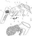
- FIGS. 1 and 2are front and exploded perspective views of an ankle support according an embodiment of the present invention
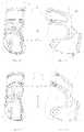
- FIGS. 20 to 23are rear perspective, top section, bottom and side views showing fitment of the ankle support to a wearer's ankle and foot;
- FIGS. 30 to 33are perspective views of embodiments of the ankle support implemented as parts of footwear.
- an ankle support 10generally comprises a rear-entry ankle cuff 12 adapted to be worn adjacently above, or partially overlapping above, lateral and medial malleoli of an ankle, and an open-heel, open-malleoli and open-toe midfoot member 14 extending forwardly and downwardly from the ankle cuff 12 .
- the midfoot member 14may comprise lateral and medial members 16 , 18 respectively extending forwardly and downwardly from the ankle cuff 12 in front of the lateral and medial malleoli. At least a portion of the midfoot member 14 may be adapted to be worn adjacent to an upper midfoot portion of, or around, a foot of a wearer. Ridges 19 may be provided on a forward upper portion 21 of the midfoot portion 14 to grip an underside of a tongue of shoe.
- the lateral and medial members 16 , 18may further extend rearwardly below the lateral and medial malleoli towards a heel of a foot of the ankle.
- Holes 17may be provided through rearward portions of the lateral and medial members 16 , 18 for ventilation, or for use as mounting holes for post-and-hole connections of optional modular components such as heel caps or C-springs (not shown).
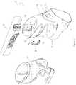
- Lower midfoot portions 20 , 22 of one or both of the lateral and medial members 16 , 18may be adapted to extend around and under an arch of the foot between the heel and a fifth metatarsal bone thereof to be adjustably releasably connectable to each other.
- the lateral and medial membersmay be adjustably releasably connectable to each other by complementary low-profile hook-and-loop fastener strips 24 , 26 moulded to respective overlapping ends of the lower midfoot portions 20 , 22 of the lateral and medial members 16 , 18 .
- the lower midfoot portions 20 , 22 of the lateral and medial members 16 , 18may adjustably releasably connect to each other under the foot in various overlapping relationships to flexibly accommodate different foot sizes, shapes, widths and arch heights. As best seen in FIGS.
- the ankle cuff 12 and the midfoot member 14may have a unitary one-piece construction.
- the ankle cuff 12 and the midfoot member 14may be integrally moulded together in an elastically deformable polymeric material.
- the elastically deformable polymeric materialmay, for example, be thermoplastic urethane (TPU) such as SkythaneTM or EstaneTM.
- TPUthermoplastic urethane
- Other equivalent or alternative elastically deformable polymeric materials having a high elastic modulusmay also be used.
- the low-profile hook-and-loop fastener strips 24 , 26may be moulded to respective ends of the lower midfoot portions 20 , 22 by die cutting spaced-apart through holes 28 adjacent to respective edges of the hook-and-loop fastener strips 24 , 26 .
- the elastically deformable polymeric material moulded to form the lower midfoot portions 20 , 22may be simultaneously injection moulded through the spaced-apart through holes 28 to form a lattice (or interlaced structure or pattern) of interconnected through- and over-mouldings that securely anchor the hook-and-loop fastener strips 24 , 26 to the respective ends of the lower midfoot portions 20 , 22 .
- Other equivalent or alternative methods of moulding over and through the hook-and-loop fastener strips 24 , 26 to mould them to the respective ends of the lower midfoot portions 20 , 22may also be used.
- the ankle support 10may further comprise padding 30 bonded to interior surfaces of the ankle cuff 12 , and to upper interior surfaces of the lateral and medial members 16 , 18 .
- the padding 30may, for example, comprise EVA (ethylene vinyl acetate copolymer) foam. Other equivalent or alternative padding materials may also be used.
- the ankle support 10may further comprise a free-floating underfoot liner 32 extending downwardly from the padding 30 to overlie lower interior surfaces of the lateral and medial members 16 , 18 .
- the liner 32may be bonded and/or sewn to the padding 30 .
- the liner 32may, for example, comprise neoprene. Other equivalent or alternative liner materials may also be used.
- FIGS. 20 and 21illustrate adjustment of the adjustment strap 34 of the ankle cuff 12 .
- the adjustment strap 34may be threaded through and tensioned against the lateral and medial anchor posts 36 , 38 , and then looped back to overlie exterior of the medial portion of the ankle cuff 12 .
- One end of the adjustment strap 34may have spaced-apart complementary low-profile hook-and-loop fastener strips that engage to anchor around the medial anchor post 36 .
- Complementary low-profile hook-and-loop fastener stripsmay also be respectively provided on the other free end of the cuff adjustment strap 34 and the exterior of the medial portion of the ankle cuff 12 .
- FIGS. 12 to 19illustrate that, in use, the ankle support 10 may provide functional ankle support to prevent and/or treat ankle injury, while also providing significantly increased degrees of natural ankle movement in plantar flexion and dorsiflexion, and inversion and eversion. While it is not intended to be bound to any particular theory, it is believed that the ankle cuff 12 and medial and lateral members 16 , 18 of the midfoot member 14 generate passive opposing/resistive torques to support and protect the major ligaments in the ankle joint. For example, the anterior talofibular ligament (ATFL) originates from the lateral malleolus of the Fibula and inserts into the lateral surface of the talus.
- ATFLanterior talofibular ligament
- the calcaneofibular ligamentoriginates from the lateral malleolus of the fibula and inserts into the lateral surface of the calcaneous.
- the ankle support 10may experience a tensile force that results in an opposing torque acting about a rotational axis similar to that acting as a result of the CFL under load.
- the ankle support 10may experience a tensile force that results in an opposing torque acting about a rotational axis similar to that acting as a result of the ATFL under load.
- the ankle support 10may offer an alternate load path to indirectly replicate the action of the ATFL and to a lesser extent, the CFL. It may provide this by restricting the extent to which the whole foot can rotate relative to the lower leg.
- the urethane shell across the lateral anterior area of the ankle support 10experiences tensile stress. This tensile stress may cause the ankle cuff 12 to pull down and anchor above the malleoli.
- the in-shoe portion of the ankle support 10may capture the fifth metatarsal region of the foot, causing a resistive torque that acts to oppose the external force causing the injurious ankle inversion.
- This opposing torquemay work to reduce the inversion rate of the ankle joint as a whole, which in turn results in a reduced inversion angle.
- the reduction in inversion rate and angletranslates to a reduced degree of rotation of the bones in the ankle joint, particularly the talus and calcaneous. This may result in a reduced magnitude of strain experienced by the ligaments that connect these bones to the fibular and tibia bones of the lower leg. This may in turn reduce the likelihood of injury to these ligaments.
- the higher the degree of plantar flexion (pointing toes down) during inversionthe higher the tensile stress experienced by the ankle support 10 and the higher the opposing torque.
- the padding and liner across the anterior and lateral surface of the footmay compress against the skin under load to serve two purposes.
- this compressionmay prevent slippage between the ankle support 10 and foot by enhancing the capacity to transfer shear forces between the ankle support 10 and the wearer's skin. This may also have a net effect of increasing the torque opposing the external inversion forces.
- the compressionmay create a light pressure force across a large surface of the ankle joint such that the wearer may feel the ankle support 10 resisting inversion. The higher the inversion angle, the higher the pressure. This in turn may assist the wearer's proprioceptive capacity by providing enhanced feedback for the wearer to know the orientation of their ankle. This may in turn allow the wearer to better coordinate the movement of their ankle through greater ankle muscle coordination and thereby reduce the likelihood of ankle injury.
- Other equivalent or alternative biomechanical modes of action to reduce and/or treat ankle injurymay also be provided by the ankle support 10 .
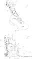
- FIG. 29illustrates an alternative spat embodiment of the ankle support 10 in which the lateral and medial members 16 , 18 of the midfoot member 14 may be releasably adjustably connectable to a separate underfoot section 52 by complementary low-profile hook-and-loop fasteners on lateral and medial sides of the shoe.
- the underfoot section 52may comprise lateral and medial side portions interconnected by a heel strap 50 .
- a cut-outmay be provided in the underfoot section 52 to surround the rear cleats of the shoe 48 .
- Other equivalent or alternative spat embodiments of the ankle support 10may also be used.
- FIGS. 30 to 34illustrate that other embodiments of the ankle support 10 may be integrated with, or directly or indirectly connected to, sports, work and everyday footwear, such as shoes and boots.
- FIG. 30illustrates an embodiment of the ankle support 10 in which the midfoot member 14 is connected to or incorporates an orthotic shoe insert, insole or footbed 54 .
- the midfoot member 14 of the ankle support 10may be directly or indirectly connected to lateral and medial sides of an upper of a shoe 48 , as illustrated in FIG. 31 .
- the ankle support 10may also have a knitted or woven fabric construction that is either integrally knitted or woven into the shoe upper.
- the ankle support 10may be attached onto the shoe upper through stitching, gluing, fusing or bonding to become an integral part of the final shoe upper.
- FIG. 32illustrates that the midfoot member 14 of the ankle support 10 may integrally form, or be directly or indirectly connected to, a tongue of a shoe 48 .
- FIG. 33illustrates that the ankle support 10 may be embodied as a standalone shoe tongue insert that may be inserted either between a shoe tongue and footwear laces 28 , or under the shoe tongue.
- the ankle cuff 12 and the midfoot portion 14may be reinforced by a resilient exoskeleton 56 .
- the resilient exoskeleton 56may be removably connected to the ankle cuff 12 and the midfoot portion 14 by post-and-hole connections 58 .
- postsmay be provided on the resilient exoskeleton 56 that press fit into holes provided through the ankle cuff 12 .
- the resilient exoskeletonmay be a moulding in a polymeric material that is relatively more rigid than the TPU of the ankle cuff 12 and the midfoot member 14 , for example, nylon or polypropylene.
Landscapes
- Health & Medical Sciences (AREA)
- Nursing (AREA)
- Orthopedic Medicine & Surgery (AREA)
- Engineering & Computer Science (AREA)
- Biomedical Technology (AREA)
- Heart & Thoracic Surgery (AREA)
- Vascular Medicine (AREA)
- Life Sciences & Earth Sciences (AREA)
- Animal Behavior & Ethology (AREA)
- General Health & Medical Sciences (AREA)
- Public Health (AREA)
- Veterinary Medicine (AREA)
- Orthopedics, Nursing, And Contraception (AREA)
- Footwear And Its Accessory, Manufacturing Method And Apparatuses (AREA)
- Socks And Pantyhose (AREA)
Abstract
Description
- a rear-entry ankle cuff adapted to be worn adjacently above lateral and medial malleoli of an ankle; and
- an open-heel, open-malleoli and open-toe midfoot member extending forwardly and downwardly from the ankle cuff.
Claims (12)
Priority Applications (1)
| Application Number | Priority Date | Filing Date | Title |
|---|---|---|---|
| US15/328,597US11559419B2 (en) | 2014-07-25 | 2015-07-27 | Functional ankle supports with improved movement and comfort |
Applications Claiming Priority (3)
| Application Number | Priority Date | Filing Date | Title |
|---|---|---|---|
| US201462028866P | 2014-07-25 | 2014-07-25 | |
| US15/328,597US11559419B2 (en) | 2014-07-25 | 2015-07-27 | Functional ankle supports with improved movement and comfort |
| PCT/AU2015/000441WO2016011493A1 (en) | 2014-07-25 | 2015-07-27 | Functional ankle supports with improved movement and comfort |
Publications (2)
| Publication Number | Publication Date |
|---|---|
| US20170216073A1 US20170216073A1 (en) | 2017-08-03 |
| US11559419B2true US11559419B2 (en) | 2023-01-24 |
Family
ID=55162316
Family Applications (1)
| Application Number | Title | Priority Date | Filing Date |
|---|---|---|---|
| US15/328,597Active2036-07-25US11559419B2 (en) | 2014-07-25 | 2015-07-27 | Functional ankle supports with improved movement and comfort |
Country Status (10)
| Country | Link |
|---|---|
| US (1) | US11559419B2 (en) |
| EP (1) | EP3171832B1 (en) |
| JP (1) | JP2017521145A (en) |
| KR (1) | KR20170035942A (en) |
| CN (1) | CN106659579B (en) |
| AU (1) | AU2015292252B2 (en) |
| BR (1) | BR112017001438A2 (en) |
| CA (1) | CA2951286A1 (en) |
| MX (1) | MX392011B (en) |
| WO (1) | WO2016011493A1 (en) |
Families Citing this family (7)
| Publication number | Priority date | Publication date | Assignee | Title |
|---|---|---|---|---|
| US11617672B2 (en) | 2016-06-27 | 2023-04-04 | Rubber City Bracing Company Llc | Dynamic tension brace or support |
| US20200170827A1 (en)* | 2017-05-24 | 2020-06-04 | Arched Bow LLC | Distributive Foot Sleeve for Relieving Pressure in a Ski Boots and the Like |
| CA3066418A1 (en)* | 2017-06-12 | 2018-12-20 | Extremity Development Company, Llc | Living hinge for athletic brace or support |
| FR3079741B1 (en)* | 2018-04-05 | 2022-06-10 | Espace Ortho Scoliose Sas | FLEXIBLE LEG ORTHOSIS |
| KR102364654B1 (en)* | 2019-11-20 | 2022-02-18 | 심민수 | Pet non-slip shoes |
| WO2022187561A1 (en)* | 2021-03-03 | 2022-09-09 | Rubber City Bracing Company Llc | Universal dynamic athletic ankle brace and add-on interior stirrup support system |
| FR3122567B1 (en)* | 2021-05-07 | 2023-06-02 | Roig Agnes | FOOT PROTECTION DEVICE AND METHOD FOR MAKING THIS DEVICE |
Citations (24)
| Publication number | Priority date | Publication date | Assignee | Title |
|---|---|---|---|---|
| US3504668A (en)* | 1967-09-13 | 1970-04-07 | Robert E Boudon | Foot support |
| US5219324A (en)* | 1992-03-12 | 1993-06-15 | Charles Hall | Anterior dorsal ankle foot orthoses |
| WO1994005236A1 (en) | 1992-08-27 | 1994-03-17 | Craig John Hubbard | An ankle brace |
| US5452527A (en)* | 1993-02-11 | 1995-09-26 | Medical Specialties, Inc. | Shoe for a foot cast |
| US5527269A (en) | 1993-12-24 | 1996-06-18 | Medi Bayreuth Gmbh & Co. | Ankle joint orthesis |
| US5897520A (en)* | 1996-12-12 | 1999-04-27 | Active Ankle Systems, Inc. | Unitary dorsal night splint |
| US6022332A (en)* | 1997-06-12 | 2000-02-08 | Private Label Creations, Inc. | Ankle brace allowing flexion and extension |
| WO2004043289A2 (en) | 2002-11-07 | 2004-05-27 | Ossur Hf | Ankle-foot orthosis |
| US20050222531A1 (en)* | 2002-06-22 | 2005-10-06 | Moore Timothy I | Ankle braces |
| US20060084899A1 (en)* | 2004-10-04 | 2006-04-20 | Verkade Drew R | Hinged ankle brace |
| US20070010773A1 (en)* | 2003-04-14 | 2007-01-11 | Watts Robert J | Ankle-foot orthosis |
| US20070021706A1 (en)* | 2005-07-20 | 2007-01-25 | Wellgate Products, Llc | Orthopedic devices with compressive elastomer formed directly onto a base material |
| US20080294082A1 (en)* | 2007-05-21 | 2008-11-27 | Julia Chang | Orthopedic device |
| US20100036306A1 (en)* | 2008-08-05 | 2010-02-11 | Michel Lussier | Support Device for a Joint |
| US20100137770A1 (en)* | 2008-12-02 | 2010-06-03 | Arni Thor Ingimundarson | Ankle brace |
| US20110067271A1 (en)* | 2009-09-21 | 2011-03-24 | Nike, Inc. | Protective Boot |
| US20120101417A1 (en)* | 2009-02-24 | 2012-04-26 | Mark Joseph | Composite material for custom fitted products |
| US20120302933A1 (en)* | 2011-05-27 | 2012-11-29 | Doak Ostergard | Ankle brace |
| US20130138028A1 (en)* | 2011-11-29 | 2013-05-30 | Nike, Inc. | Ankle and Foot Support System |
| DE102012011466A1 (en) | 2012-06-12 | 2013-12-12 | Otto Bock Healthcare Gmbh | Ankle-foot orthosis |
| US20150065935A1 (en)* | 2013-08-29 | 2015-03-05 | Joseph C. Smith | Prefabricated walking boot |
| US9393146B2 (en)* | 2008-04-04 | 2016-07-19 | Medical Specialties, Incorporated | Ankle stabilizing device comprising an above-the-foot body member and integrated flexible non-stretch ankle belt |
| US20160278948A1 (en)* | 2015-03-27 | 2016-09-29 | Other Lab, Llc | Lower-leg exoskeleton system and method |
| US9827131B2 (en)* | 2004-12-06 | 2017-11-28 | Dorset Orthopaedic Company Limited | Ankle-foot orthosis |
Family Cites Families (17)
| Publication number | Priority date | Publication date | Assignee | Title |
|---|---|---|---|---|
| DE4318588C1 (en)* | 1993-06-04 | 1994-08-25 | Beiersdorf Ag | Ankle joint orthesis with U-shaped joint cuff and flexible web |
| US5822887A (en)* | 1993-06-22 | 1998-10-20 | Turner; Gregory D. | Over-the-shoe athletic spat |
| CN2196470Y (en)* | 1994-06-11 | 1995-05-10 | 赵大权 | Stably curing device for ankle joint |
| NL1004931C2 (en)* | 1997-01-05 | 1998-07-08 | Floor Schrijver | Medium weight ankle support. |
| JP2001353172A (en)* | 2000-06-15 | 2001-12-25 | Shiyomi Gishi Seisakusho:Kk | Equipment for correction of talipes equinovarus |
| DE20018575U1 (en)* | 2000-10-31 | 2002-03-21 | Ferd. Hauber GmbH & Co. KG, 72622 Nürtingen | Textile orthosis to compensate for spastic foot lift paresis |
| JP2002339123A (en)* | 2001-05-09 | 2002-11-27 | Tomihiro Nagumo | Supporter having cushioning material |
| US7014621B2 (en)* | 2002-12-06 | 2006-03-21 | Mueller Sports Medicine, Inc. | Ankle brace |
| GB0308607D0 (en)* | 2003-04-14 | 2003-05-21 | Watts Robert J | Ankle-foot orthosis |
| US7128725B2 (en)* | 2003-10-16 | 2006-10-31 | David Rabe | Ankle brace |
| WO2007149489A2 (en)* | 2006-06-19 | 2007-12-27 | Winds Enterprises, Inc. | Ankle brace |
| US20080208094A1 (en)* | 2007-02-28 | 2008-08-28 | Eric Lee Gaylord | Orthotic Device Having Adjustable Stabilizing Member and Tensioning Arms |
| DE102007057578A1 (en)* | 2007-11-28 | 2009-06-10 | Otto Bock Healthcare Ip Gmbh & Co. Kg | Sprunggelenkorthesensystem |
| WO2011113473A1 (en)* | 2010-03-15 | 2011-09-22 | Orfit Industries | Immobilization device |
| US9675490B2 (en)* | 2012-06-19 | 2017-06-13 | Pod Global Ip Pty Ltd | Ankle supports |
| FR2999417B1 (en)* | 2012-12-14 | 2015-02-06 | Benoit Causse | ORTHOPEDIC DEVICE FOR A LOWER HUMAN MEMBER AND SHOE EQUIPPED WITH SUCH A DEVICE |
| CN203591362U (en)* | 2013-12-02 | 2014-05-14 | 庄汝杰 | Supporting device for rear half portion of foot |
- 2015
- 2015-07-27KRKR1020177003809Apatent/KR20170035942A/ennot_activeWithdrawn
- 2015-07-27EPEP15825540.6Apatent/EP3171832B1/enactiveActive
- 2015-07-27CNCN201580038558.1Apatent/CN106659579B/enactiveActive
- 2015-07-27BRBR112017001438Apatent/BR112017001438A2/ennot_activeApplication Discontinuation
- 2015-07-27USUS15/328,597patent/US11559419B2/enactiveActive
- 2015-07-27JPJP2016572820Apatent/JP2017521145A/enactivePending
- 2015-07-27MXMX2017001171Apatent/MX392011B/enunknown
- 2015-07-27CACA2951286Apatent/CA2951286A1/ennot_activeAbandoned
- 2015-07-27WOPCT/AU2015/000441patent/WO2016011493A1/enactiveApplication Filing
- 2015-07-27AUAU2015292252Apatent/AU2015292252B2/enactiveActive
Patent Citations (26)
| Publication number | Priority date | Publication date | Assignee | Title |
|---|---|---|---|---|
| US3504668A (en)* | 1967-09-13 | 1970-04-07 | Robert E Boudon | Foot support |
| US5219324A (en)* | 1992-03-12 | 1993-06-15 | Charles Hall | Anterior dorsal ankle foot orthoses |
| US5944678A (en)* | 1992-08-27 | 1999-08-31 | Hubbard; Craig John | Ankle brace |
| WO1994005236A1 (en) | 1992-08-27 | 1994-03-17 | Craig John Hubbard | An ankle brace |
| US5452527A (en)* | 1993-02-11 | 1995-09-26 | Medical Specialties, Inc. | Shoe for a foot cast |
| US5527269A (en) | 1993-12-24 | 1996-06-18 | Medi Bayreuth Gmbh & Co. | Ankle joint orthesis |
| US5897520A (en)* | 1996-12-12 | 1999-04-27 | Active Ankle Systems, Inc. | Unitary dorsal night splint |
| US6022332A (en)* | 1997-06-12 | 2000-02-08 | Private Label Creations, Inc. | Ankle brace allowing flexion and extension |
| US20050222531A1 (en)* | 2002-06-22 | 2005-10-06 | Moore Timothy I | Ankle braces |
| WO2004043289A2 (en) | 2002-11-07 | 2004-05-27 | Ossur Hf | Ankle-foot orthosis |
| US20070010773A1 (en)* | 2003-04-14 | 2007-01-11 | Watts Robert J | Ankle-foot orthosis |
| US20060084899A1 (en)* | 2004-10-04 | 2006-04-20 | Verkade Drew R | Hinged ankle brace |
| US9827131B2 (en)* | 2004-12-06 | 2017-11-28 | Dorset Orthopaedic Company Limited | Ankle-foot orthosis |
| US20070021706A1 (en)* | 2005-07-20 | 2007-01-25 | Wellgate Products, Llc | Orthopedic devices with compressive elastomer formed directly onto a base material |
| US20080294082A1 (en)* | 2007-05-21 | 2008-11-27 | Julia Chang | Orthopedic device |
| US9393146B2 (en)* | 2008-04-04 | 2016-07-19 | Medical Specialties, Incorporated | Ankle stabilizing device comprising an above-the-foot body member and integrated flexible non-stretch ankle belt |
| US20100036306A1 (en)* | 2008-08-05 | 2010-02-11 | Michel Lussier | Support Device for a Joint |
| US20100137770A1 (en)* | 2008-12-02 | 2010-06-03 | Arni Thor Ingimundarson | Ankle brace |
| US20120101417A1 (en)* | 2009-02-24 | 2012-04-26 | Mark Joseph | Composite material for custom fitted products |
| US20110067271A1 (en)* | 2009-09-21 | 2011-03-24 | Nike, Inc. | Protective Boot |
| US20120302933A1 (en)* | 2011-05-27 | 2012-11-29 | Doak Ostergard | Ankle brace |
| US20130138028A1 (en)* | 2011-11-29 | 2013-05-30 | Nike, Inc. | Ankle and Foot Support System |
| DE102012011466A1 (en) | 2012-06-12 | 2013-12-12 | Otto Bock Healthcare Gmbh | Ankle-foot orthosis |
| US20150148725A1 (en) | 2012-06-12 | 2015-05-28 | Otto Bock Healthcare Gmbh | Ankle/foot orthosis |
| US20150065935A1 (en)* | 2013-08-29 | 2015-03-05 | Joseph C. Smith | Prefabricated walking boot |
| US20160278948A1 (en)* | 2015-03-27 | 2016-09-29 | Other Lab, Llc | Lower-leg exoskeleton system and method |
Non-Patent Citations (3)
| Title |
|---|
| Exoform Dorsal Night Splint and Airform Night Splint [downloaded from the Internet Sep. 18, 2015] 2 pages. |
| International Search Report and Written Opinion for PCT/AU2015/000441, dated Sep. 25, 2015 (10 pages). |
| IPRP for International Application PCT/AU2015/000441, dated Aug. 30, 3016. |
Also Published As
| Publication number | Publication date |
|---|---|
| KR20170035942A (en) | 2017-03-31 |
| CA2951286A1 (en) | 2016-01-28 |
| JP2017521145A (en) | 2017-08-03 |
| EP3171832B1 (en) | 2019-08-21 |
| AU2015292252B2 (en) | 2020-03-19 |
| CN106659579A (en) | 2017-05-10 |
| US20170216073A1 (en) | 2017-08-03 |
| WO2016011493A1 (en) | 2016-01-28 |
| MX2017001171A (en) | 2017-08-02 |
| EP3171832A1 (en) | 2017-05-31 |
| BR112017001438A2 (en) | 2017-12-05 |
| CN106659579B (en) | 2019-09-27 |
| MX392011B (en) | 2025-03-21 |
| EP3171832A4 (en) | 2018-04-18 |
| AU2015292252A1 (en) | 2017-01-12 |
Similar Documents
| Publication | Publication Date | Title |
|---|---|---|
| US11559419B2 (en) | Functional ankle supports with improved movement and comfort | |
| US9532625B2 (en) | Athletic shoe | |
| US5810754A (en) | Ankle orthotic | |
| US5317820A (en) | Multi-application ankle support footwear | |
| US12004986B2 (en) | Foot and ankle support article | |
| US7243444B2 (en) | Athletic footwear and the like with integral supinator device | |
| US7267656B2 (en) | Ankle brace | |
| US11497644B2 (en) | External ankle brace | |
| US20090076428A1 (en) | Ambidextrous ankle support | |
| US9414950B1 (en) | Rear entry ankle brace with medial and lateral access | |
| EP1575462B1 (en) | Ankle brace | |
| US12290461B2 (en) | External ankle brace | |
| CA2909417A1 (en) | Orthotic foot support | |
| US20250169976A1 (en) | External ankle brace | |
| US20230414394A1 (en) | Ankle brace | |
| US20170071285A1 (en) | Foot support assembly for lateral and medial stability of foot | |
| EP3533352B1 (en) | Minimalist barefoot shoes for correcting flatfeet | |
| WO2013082385A1 (en) | Improved athletic shoe | |
| RU206419U1 (en) | Protective orthopedic boots | |
| WO2023168337A2 (en) | Stabilizing footwear |
Legal Events
| Date | Code | Title | Description |
|---|---|---|---|
| AS | Assignment | Owner name:POD GLOBAL IP PTY LTD, AUSTRALIA Free format text:ASSIGNMENT OF ASSIGNORS INTEREST;ASSIGNOR:MALONEY, GEOFFREY PAUL;REEL/FRAME:041135/0353 Effective date:20170131 | |
| STPP | Information on status: patent application and granting procedure in general | Free format text:DOCKETED NEW CASE - READY FOR EXAMINATION | |
| STPP | Information on status: patent application and granting procedure in general | Free format text:NON FINAL ACTION MAILED | |
| STPP | Information on status: patent application and granting procedure in general | Free format text:RESPONSE TO NON-FINAL OFFICE ACTION ENTERED AND FORWARDED TO EXAMINER | |
| STPP | Information on status: patent application and granting procedure in general | Free format text:FINAL REJECTION MAILED | |
| STPP | Information on status: patent application and granting procedure in general | Free format text:DOCKETED NEW CASE - READY FOR EXAMINATION | |
| STPP | Information on status: patent application and granting procedure in general | Free format text:NON FINAL ACTION MAILED | |
| STPP | Information on status: patent application and granting procedure in general | Free format text:RESPONSE TO NON-FINAL OFFICE ACTION ENTERED AND FORWARDED TO EXAMINER | |
| STPP | Information on status: patent application and granting procedure in general | Free format text:NOTICE OF ALLOWANCE MAILED -- APPLICATION RECEIVED IN OFFICE OF PUBLICATIONS | |
| STPP | Information on status: patent application and granting procedure in general | Free format text:PUBLICATIONS -- ISSUE FEE PAYMENT VERIFIED | |
| STCF | Information on status: patent grant | Free format text:PATENTED CASE |