US11559330B2 - Surgical cannula with removable pressure seal - Google Patents
Surgical cannula with removable pressure sealDownload PDFInfo
- Publication number
- US11559330B2 US11559330B2US17/173,531US202117173531AUS11559330B2US 11559330 B2US11559330 B2US 11559330B2US 202117173531 AUS202117173531 AUS 202117173531AUS 11559330 B2US11559330 B2US 11559330B2
- Authority
- US
- United States
- Prior art keywords
- cannula
- seal structure
- surgical
- cannula body
- valve
- Prior art date
- Legal status (The legal status is an assumption and is not a legal conclusion. Google has not performed a legal analysis and makes no representation as to the accuracy of the status listed.)
- Active
Links
- 238000001356surgical procedureMethods0.000claimsabstractdescription34
- 239000000463materialSubstances0.000claimsabstractdescription9
- 238000003780insertionMethods0.000claimsdescription44
- 230000037431insertionEffects0.000claimsdescription44
- 238000000034methodMethods0.000claimsdescription7
- 239000013536elastomeric materialSubstances0.000claimsdescription4
- 239000007943implantSubstances0.000claimsdescription4
- 239000004743PolypropyleneSubstances0.000claimsdescription2
- 229920000515polycarbonatePolymers0.000claimsdescription2
- 239000004417polycarbonateSubstances0.000claimsdescription2
- -1polypropylenePolymers0.000claimsdescription2
- 229920001155polypropylenePolymers0.000claimsdescription2
- 210000001519tissueAnatomy0.000description29
- 239000012530fluidSubstances0.000description15
- 210000000591tricuspid valveAnatomy0.000description15
- 241001631457CannulaSpecies0.000description14
- 239000007788liquidSubstances0.000description14
- 239000000758substrateSubstances0.000description14
- 230000000717retained effectEffects0.000description5
- 230000002262irrigationEffects0.000description4
- 238000003973irrigationMethods0.000description4
- 239000011800void materialSubstances0.000description4
- 241001465754MetazoaSpecies0.000description3
- 238000012800visualizationMethods0.000description3
- 230000000740bleeding effectEffects0.000description2
- 210000003205muscleAnatomy0.000description2
- 210000000513rotator cuffAnatomy0.000description2
- 238000007789sealingMethods0.000description2
- 210000005166vasculatureAnatomy0.000description2
- 241000272525Anas platyrhynchosSpecies0.000description1
- FAPWRFPIFSIZLT-UHFFFAOYSA-MSodium chlorideChemical compound[Na+].[Cl-]FAPWRFPIFSIZLT-UHFFFAOYSA-M0.000description1
- 239000000853adhesiveSubstances0.000description1
- 230000001070adhesive effectEffects0.000description1
- 239000008280bloodSubstances0.000description1
- 210000004369bloodAnatomy0.000description1
- 238000004891communicationMethods0.000description1
- 238000000605extractionMethods0.000description1
- 210000005224forefingerAnatomy0.000description1
- 230000002496gastric effectEffects0.000description1
- 238000001990intravenous administrationMethods0.000description1
- 239000000644isotonic solutionSubstances0.000description1
- 210000003127kneeAnatomy0.000description1
- 210000003041ligamentAnatomy0.000description1
- 230000000670limiting effectEffects0.000description1
- 230000036961partial effectEffects0.000description1
- 229920001296polysiloxanePolymers0.000description1
- 230000000284resting effectEffects0.000description1
- 230000002441reversible effectEffects0.000description1
- 239000000523sampleSubstances0.000description1
- 238000009958sewingMethods0.000description1
- 239000011780sodium chlorideSubstances0.000description1
- 210000003813thumbAnatomy0.000description1
- 238000003466weldingMethods0.000description1
Images


Classifications
- A—HUMAN NECESSITIES
- A61—MEDICAL OR VETERINARY SCIENCE; HYGIENE
- A61B—DIAGNOSIS; SURGERY; IDENTIFICATION
- A61B17/00—Surgical instruments, devices or methods
- A61B17/34—Trocars; Puncturing needles
- A61B17/3462—Trocars; Puncturing needles with means for changing the diameter or the orientation of the entrance port of the cannula, e.g. for use with different-sized instruments, reduction ports, adapter seals
- A—HUMAN NECESSITIES
- A61—MEDICAL OR VETERINARY SCIENCE; HYGIENE
- A61B—DIAGNOSIS; SURGERY; IDENTIFICATION
- A61B17/00—Surgical instruments, devices or methods
- A61B17/34—Trocars; Puncturing needles
- A61B17/3417—Details of tips or shafts, e.g. grooves, expandable, bendable; Multiple coaxial sliding cannulas, e.g. for dilating
- A61B17/3421—Cannulas
- A61B17/3423—Access ports, e.g. toroid shape introducers for instruments or hands
- A—HUMAN NECESSITIES
- A61—MEDICAL OR VETERINARY SCIENCE; HYGIENE
- A61B—DIAGNOSIS; SURGERY; IDENTIFICATION
- A61B17/00—Surgical instruments, devices or methods
- A61B17/34—Trocars; Puncturing needles
- A61B17/3468—Trocars; Puncturing needles for implanting or removing devices, e.g. prostheses, implants, seeds, wires
- A—HUMAN NECESSITIES
- A61—MEDICAL OR VETERINARY SCIENCE; HYGIENE
- A61B—DIAGNOSIS; SURGERY; IDENTIFICATION
- A61B17/00—Surgical instruments, devices or methods
- A61B17/34—Trocars; Puncturing needles
- A61B17/3498—Valves therefor, e.g. flapper valves, slide valves
- A—HUMAN NECESSITIES
- A61—MEDICAL OR VETERINARY SCIENCE; HYGIENE
- A61B—DIAGNOSIS; SURGERY; IDENTIFICATION
- A61B17/00—Surgical instruments, devices or methods
- A61B2017/00477—Coupling
- A—HUMAN NECESSITIES
- A61—MEDICAL OR VETERINARY SCIENCE; HYGIENE
- A61B—DIAGNOSIS; SURGERY; IDENTIFICATION
- A61B17/00—Surgical instruments, devices or methods
- A61B17/34—Trocars; Puncturing needles
- A61B2017/348—Means for supporting the trocar against the body or retaining the trocar inside the body
- A61B2017/3482—Means for supporting the trocar against the body or retaining the trocar inside the body inside
- A61B2017/349—Trocar with thread on outside
- A—HUMAN NECESSITIES
- A61—MEDICAL OR VETERINARY SCIENCE; HYGIENE
- A61B—DIAGNOSIS; SURGERY; IDENTIFICATION
- A61B17/00—Surgical instruments, devices or methods
- A61B17/34—Trocars; Puncturing needles
- A61B2017/348—Means for supporting the trocar against the body or retaining the trocar inside the body
- A61B2017/3492—Means for supporting the trocar against the body or retaining the trocar inside the body against the outside of the body
- A—HUMAN NECESSITIES
- A61—MEDICAL OR VETERINARY SCIENCE; HYGIENE
- A61F—FILTERS IMPLANTABLE INTO BLOOD VESSELS; PROSTHESES; DEVICES PROVIDING PATENCY TO, OR PREVENTING COLLAPSING OF, TUBULAR STRUCTURES OF THE BODY, e.g. STENTS; ORTHOPAEDIC, NURSING OR CONTRACEPTIVE DEVICES; FOMENTATION; TREATMENT OR PROTECTION OF EYES OR EARS; BANDAGES, DRESSINGS OR ABSORBENT PADS; FIRST-AID KITS
- A61F2/00—Filters implantable into blood vessels; Prostheses, i.e. artificial substitutes or replacements for parts of the body; Appliances for connecting them with the body; Devices providing patency to, or preventing collapsing of, tubular structures of the body, e.g. stents
- A61F2/02—Prostheses implantable into the body
- A61F2/30—Joints
- A61F2/46—Special tools for implanting artificial joints
- A61F2/4601—Special tools for implanting artificial joints for introducing bone substitute, for implanting bone graft implants or for compacting them in the bone cavity
- A—HUMAN NECESSITIES
- A61—MEDICAL OR VETERINARY SCIENCE; HYGIENE
- A61F—FILTERS IMPLANTABLE INTO BLOOD VESSELS; PROSTHESES; DEVICES PROVIDING PATENCY TO, OR PREVENTING COLLAPSING OF, TUBULAR STRUCTURES OF THE BODY, e.g. STENTS; ORTHOPAEDIC, NURSING OR CONTRACEPTIVE DEVICES; FOMENTATION; TREATMENT OR PROTECTION OF EYES OR EARS; BANDAGES, DRESSINGS OR ABSORBENT PADS; FIRST-AID KITS
- A61F2/00—Filters implantable into blood vessels; Prostheses, i.e. artificial substitutes or replacements for parts of the body; Appliances for connecting them with the body; Devices providing patency to, or preventing collapsing of, tubular structures of the body, e.g. stents
- A61F2/0063—Implantable repair or support meshes, e.g. hernia meshes
- A61F2002/0072—Delivery tools therefor
Definitions
- the present disclosurerelates to the field of surgical cannulas that may be temporarily inserted into living tissue.
- Cannulasmay be used during surgery to introduce tools or substrates into a human or animal body.
- Surgical cannulasare generally well-known in the art of arthroscopic surgery.
- various types of cannulasare used to control the inflow or outflow of fluids, to allow access for tools into the tissue, and for other functions.
- a graft or other substrate materialmay be introduced into a surgical site.
- many arthroscopic surgeriessuch as joint surgeries, use pressurized irrigation fluid to keep tissue separated apart from other tissue.
- pressurized irrigation fluidmay be used to aid in visualization of the surgical site as well as to prevent bleeding from vasculature surrounding the surgical cuts.
- Other types of surgeriessuch as gastrointestinal procedures, use pressurized gas to provide access to and visualization of the surgical site.
- the disclosureprovides a surgical cannula comprising: a seal structure including at least one valve; and a cannula body, including: an insertion portion having a distal opening that is configured to be inserted into tissue, and a receiving portion that includes a proximal opening and is configured to reversibly receive the seal structure; wherein the seal structure is configured to removably associate with the proximal opening of the cannula body; and wherein the seal structure is configured to retain a positive pressure within the cannula body when engaged with the cannula body, and the seal structure is configured to retain a positive pressure within the cannula body when an object is inserted through the cannula and the seal structure.
- the disclosureprovides a surgical cannula comprising: a seal structure including a first valve and a second valve; and a cannula body, including: an insertion portion that includes a distal opening and is configured to be inserted into tissue, and a receiving portion that includes a proximal opening and is configured to reversibly receive the seal structure; wherein the seal structure reversibly covers the proximal opening of the cannula body; wherein the seal structure is configured to retain a positive pressure within the cannula body when an object is inserted through the cannula.
- this disclosureprovides a surgical cannula comprising: a seal structure including at least one valve; and a cannula body, including an insertion portion that includes a distal opening and is configured to be inserted into tissue, and a receiving portion that includes a proximal opening and is configured to reversibly receive the seal structure; wherein the seal structure is configured to retain a positive pressure within the cannula body when an object is inserted through the cannula and the seal structure; and wherein the cannula body further includes one or more suture attachment structures configured to hold a suture so as to anchor the cannula to tissue into which the insertion portion has been inserted.
- FIG. 1is a perspective top view of a first embodiment of a surgical cannula in accordance with this disclosure
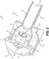
- FIG. 2is a perspective cross-sectional view of the first embodiment of a surgical cannula in accordance with this disclosure
- FIG. 3is a perspective bottom view of the first embodiment of a surgical cannula in accordance with this disclosure
- FIG. 4is a cross-sectional view of a first surgical procedure that involves the use of a surgical cannula in accordance with this disclosure
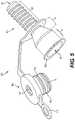
- FIG. 5is a perspective view of the first embodiment of a surgical cannula with the removable top separated from the cannula body;
- FIG. 6is another perspective view of the surgical cannula with the removable top separated from the cannula body
- FIG. 7is a cross-sectional view of a second surgical procedure that involves the use of a surgical cannula in accordance with this disclosure
- FIG. 8is a perspective top view of a second embodiment of a surgical cannula in accordance with this disclosure.
- FIG. 9is an exploded view of the several subcomponents making up the second embodiment of a surgical cannula in accordance with this disclosure.
- FIG. 10is a perspective top view of the second embodiment of a surgical cannula with the removable top secured to the cannula;
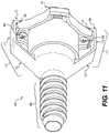
- FIG. 11is a perspective bottom view of the second embodiment of a surgical cannula with the removable top secured to the cannula;
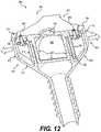
- FIG. 12is a first perspective cross-sectional view of the second embodiment of a surgical cannula in accordance with this disclosure.
- FIG. 13is a second perspective cross-sectional view of the second embodiment of a surgical cannula in accordance with this disclosure.
- FIG. 14is a perspective top view of a third embodiment of a surgical cannula in accordance with this disclosure.
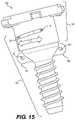
- FIG. 15is a side view of the third embodiment of a surgical cannula in accordance with this disclosure.
- FIG. 16is a first side exploded view of the several subcomponents of the third embodiment of a surgical cannula in accordance with this disclosure.
- FIG. 17is a second side exploded view of the several subcomponents of the third embodiment of a surgical cannula in accordance with this disclosure, and a tool used in conjunction with the cannula;
- FIG. 18is a cross-sectional view of the third embodiment of a surgical cannula in accordance with this disclosure.
- FIG. 19is a perspective top view of a fourth embodiment of a surgical cannula in accordance with this disclosure.
- FIG. 20is a cross-sectional view of the fourth embodiment of a surgical cannula in accordance with this disclosure.
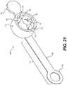
- FIG. 21is a perspective bottom view of the fourth embodiment of a surgical cannula in accordance with this disclosure.
- FIG. 22is an perspective cross-sectional view of the fourth embodiment of a surgical cannula in accordance with this disclosure.
- FIG. 23is a perspective view of a fifth embodiment of a surgical cannula in accordance with this disclosure.
- FIG. 24is a perspective view of the fifth embodiment of a surgical cannula with a tool therein;
- FIG. 25is a perspective cross-sectional view of the fifth embodiment of a surgical cannula with the tool therein;
- FIG. 26is a second perspective cross-sectional view of the fifth embodiment of a surgical cannula with the tool therein;
- FIG. 27is a perspective view of the fifth embodiment of a surgical cannula with the seal structure removed from the receiving portion of the cannula body;
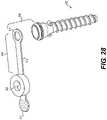
- FIG. 28is a top perspective view of the fifth embodiment of a surgical cannula with the seal structure and tether entirely removed from the cannula body;
- FIG. 29is a cross-sectional perspective view of the fifth embodiment of a surgical cannula with the seal structure removed from the cannula body.
- surgical cannulasthat include a removable seal structure that retains pressure inside the cannula.
- a cannulamay be used during arthroscopic surgery to both provide an inlet for arthroscopic tools, and also act as a port to allow introduction of a graft substrate into the surgical site.
- a cannulamay broadly refer to a tube that can be inserted into the body, and used for the delivery or extraction of fluid or other materials.
- Surgical cannulasmay generally include intravenous cannulas, nasal cannulas, or surgical cannulas.
- this disclosureis directed to surgical cannulas that may retain pressurized fluid (liquid or gas) within a surgical site when a seal structure is engaged on the cannula, while also allowing removal of the seal structure in order to permit larger items, such as tissue grafts, to be introduced through the cannula.
- pressurized fluidliquid or gas
- FIG. 1shows a first embodiment of a cannula in accordance with this disclosure.
- Cannula 100may include cannula body portion 102 that includes an insertion portion 120 , a receiving portion 128 , and a taper portion 126 between the two.
- Insertion portion 120may include a distal opening 124 in the cannula.
- Insertion portion 120may be configured to be inserted into tissue, such as a human body or an animal body, and may be generally cylindrical in shape. Insertion portion 120 may also include threads 122 on an exterior surface thereof.
- Threads 122may secure cannula 100 in the tissue, and may allow more accurate placement of the cannula 100 within the tissue by allowing a user to increase or decrease the depth to which the cannula is inserted into the tissue by rotating the cannula 100 .
- Cannula 100may also include a seal structure 104 .
- Seal structure 104may engage with receiving portion 128 .
- Seal structure 104may include a valve 106 .
- valve 106may be a tricuspid valve, as shown in FIG. 1 .
- a tricuspid valveas is generally known in the art, is a one-way valve made up of three flaps that come together at a single point. Valve 106 may therefore retain fluidic pressure inside cannula body 102 when cannula 100 is used in a surgical procedure.
- Seal structure 104may also include top portion 108 and side portion 110 . Finally, seal structure 104 may also include tether 114 that may connect seal structure 104 to cannula body portion 102 when seal structure is not engaged with receiving portion 128 .
- FIG. 2shows cannula 100 in further detail.
- FIG. 2shows a cross-sectional view of cannula 100 .
- cannula body 102may be hollow so as to allow passage of tools or tissue through the cannula 100 from a proximal end to a distal end 124 .
- insertion portion 120 of cannula body 102may be a hollow cylinder of a first gauge (diameter)
- receiving portion 128 of cannula body 102may be a hollow cylinder of a second gauge (diameter) that is larger than the first gauge
- taper portion 126may taper in gauge between the two.
- Seal structure 104may also include side portion 110 that engages with lip 129 on cannula body portion 102 to engage a seal between seal structure 104 and cannula body portion 102 .
- Lip 129may cause seal structure 104 to be securely, but reversibly, retained against cannula body portion 102 .
- seal structure 104may include first valve 106 and also second valve 107 .
- first valve 106may be a tricuspid valve and second valve 107 may also be a tricuspid valve, as shown in FIG. 2 .
- other types of valvesmay be used.
- Other embodiments discussed hereinutilize duckbill valves. In some cases, such a duckbill valve may be utilized in the embodiment shown in FIGS. 1 - 7 (e.g., substituted for one or both of the tricuspid valves).
- First valve 106 and second valve 107may be separated by a void 109 defined by seal sidewalls 105 .
- Void 109may catch any seepage of a pressurized fluid from taper portion 126 and insertion portion 120 that escapes past second valve 107 , while first valve 106 may still ensure no liquid escapes to outside of the cannula.
- FIG. 2also shows tether 114 in greater detail.
- tether 114may include arm portion 116 that connects to top portion 108 of seal structure 104 at one end of arm portion 116 . Arm portion 116 may then connect to ring portion 118 that encircles one end of insertion portion 120 of the cannula body 102 . In this way, tether 114 may connect seal structure 104 to cannula body portion 102 even when seal structure 104 is not engaged with receiving portion 126 .
- seal structure 104may be a continuous unitary piece of a single material.
- seal structure 104may be made of continuous silicone material.
- FIG. 3shows cannula 100 from a perspective bottom view.
- FIG. 3shows how cannula 100 looks when seal structure 104 is engaged with receiving portion 128 .
- second valve 107is adjacent to taper portion 126 so as to retain any pressurized fluid within a surgical site that may flow upward into insertion portion 120 and taper portion 126 .
- tab portion 112may be connected to side portion 110 of top portion 108 of seal structure 104 .
- Tab portion 112may allow a user to easily and conveniently remove seal structure 104 from engagement with cannula body portion 102 .
- a surgeonmay remove seal structure 104 from cannula body portion 102 by grasping tab 112 and pulling on tab 112 until side portion 110 no longer engages with lip 129 (see FIG. 2 for connection between side portion 110 and lip 129 ).
- FIG. 4shows one example of how a cannula in accordance with this disclosure may be used during a surgical procedure.
- a surgeon 202may operate a tool 204 that is inserted through cannula 100 , which has been inserted into a patient 208 at surgical site 206 .
- this disclosurealso provides methods of performing arthroscopic surgery using the cannula devices disclosed herein.
- the cross section of surgical site 206 shown in FIG. 4shows how the cannula is used during a surgical procedure in greater detail.
- insertion portion 120 of cannula 100may be partially implanted into the patient's tissue using threads 122 .
- Cannula 100may be introduced into the tissue by first making an incision 220 into skin tissue 210 and muscle tissue 212 such that distal end 124 will be located adjacent to the desired surgical site 226 .
- the surgical proceduremay be a rotator cuff surgery.
- desired surgical site 226may be where rotator cuff muscle and ligaments 216 attach to the humoral head 218 at the subacromial space.
- a pressurized liquid 214may be used to inflate and visualize the surgical site 226 .
- Pressurized liquid 214may be clear saline, for example.
- pressurized liquid 214may be an isotonic solution that is used to enable visualization and also prevent bleeding from vasculature surrounding the surgical site 226 .
- Pressurized liquid 214may be at a pressure of around 20-30 mmHg.
- debris or bloodmay cloud the pressurized fluid.
- the pressurized fluidmay be flushed. In doing so, the pressure and flow of the fluid may be raised significantly.
- the disclosed seal of the cannulamay be configured to sustain pressures up to about 140 mmHg.
- Cannula 100may allow surgeon 202 to introduce tool 204 into the surgical site 226 while retaining fluid 214 under pressurization.
- Tool 204may include tool shaft 222 that extends through cannula 100 and ends at tool tip 224 .
- tool shaft 222may extend through first valve 106 and second valve 107 which conform around tool shaft 222 such that pressurization 230 of the pressurized liquid 214 is contained within the surgical site 226 as well as within the insertion portion 120 and taper portion 126 of cannula 100 .
- seal structure 104may be configured to retain a positive pressure 230 within the cannula body when a tool 204 is inserted through the cannula 100 .
- FIG. 5next shows cannula 100 when seal structure 104 is not engaged with cannula body portion 102 .
- tether 114may keep seal structure 104 attached to cannula body portion 102 even when seal structure 104 is not engaged with body portion 102 .
- proximal opening 125 in receiving portion 128that is located opposite distal opening 124 in insertion portion 120 .
- Proximal opening 125may be surrounded by lip 129 , which engages with side portion 110 of seal structure 104 , as mentioned above. Seal structure 104 may therefore cover proximal opening 125 when seal structure 104 is engaged with cannula body portion 102 .
- the embodiment in FIG. 5may also include ridges 130 , 132 on seal sidewalls 105 that further ensure a tight (but reversible) fit between seal structure 104 and receiving portion 128 .
- seal sidewalls 105engage with an interior surface of receiving portion 128 . Ridges 130 , 132 may therefore abut interior surface of receiving portion 128 in order to form a seal that retains pressure.
- FIG. 6shows the embodiment of FIG. 5 from another angle, in order to show additional details of seal structure 104 .
- second valve 107may be disposed on a bottom side of seal structure 104 such that second valve 107 may be inserted into receiving portion 128 so as to be located at the most distal end of receiving portion 128 .
- Tether 114may include arm portion 116 that connects seal structure side portion 110 with ring portion 118 .
- Ring portion 118may encircle cannula body 104 at a nearest end of insertion portion 120 .
- seal structure 104may be reversibly engaged with cannula body portion 102 and thus may be removed after engagement with cannula body portion 102 .
- FIG. 7shows another surgical procedure 300 , and how cannula 100 may be used when the seal structure is removed from the cannula body portion.
- surgeon 302may perform surgery on a patient 308 at the patient's knee 306 through an insertion 320 in the patient's skin 210 and through tissue 312 surrounding the surgical site.
- a graft substrate 340is ready to be introduced into the surgical site 326 . This would typically occur after a surgical site 226 / 326 has been prepared through one or more steps involving the use of tools at the surgical site as shown in FIG. 4 .
- a method of performing arthroscopic surgery in accordance with this disclosuremay include delivering a sheet-like implant 340 through the cannula 100 to the surgical site, and securing the sheet-like implant 340 to tissue 316 at the surgical site 326 .
- pressurized liquid 314is in fluidic communication with the entire interior of cannula 100 .
- pressurized liquid 314may expand up into insertion portion 120 , taper portion 126 , and receiving portion 128 as shown.
- Tool 304may then be attached to proximal opening 125 of cannula 100 and used to introduce graft sheet-life substrate 340 into the interior of the cannula 100 and allow graft substrate 340 to travel down the length of cannula 100 to surgical site 326 along path 342 .
- Tool 304may include aspects for maintaining pressurized liquid 314 under pressure 330 during this surgical step.
- tool 304may include one or more sealing structures on the shaft of tool 304 . Such sealing structures may seal the cannula during the insertion of the graft.
- cannula 100may be configured so as to allow a graft substrate 340 to travel through it. Namely, cannula 100 may be of sufficient size to allow graft substrate 340 to fit therein.
- the gauge of the various cannula sectionsmay differ depending on the size of the patient and the type of surgery for which it is used. In addition, the relative proportions of the gauges of the different portions of the cannula may differ.
- the second gauge of receiving portion 128being larger than the first gauge of insertion portion 120 may advantageously help the sheet-like graft substrate 340 (and any supporting structures that may aid in the place of the graft substrate 340 ) roll itself up as it passes along cannula body portion 102 from proximal opening 125 to distal opening 124 .
- the shape of taper portion 126may cause the graft substrate 340 to roll up—and thereby assume a configuration that is advantageous for placement for attachment to the patient's tissue 316 t .
- the relative size of the gauges of the various sections of cannula body portion 102may therefore advantageously aid in the accomplishment of the purpose for which the cannula 100 is to be used.
- seal structure 104may be re-engaged with cannula body portion. Then, surgical tools may again be introduced into the surgical site (in order to manipulate the graft substrate 340 and attached it where needed) as shown in FIG. 4 .
- a single surgical cannula 100may both allow for the introduction of tools into a surgical site under a pressurized liquid, and also allow introduction of a graft substrate into the surgical site.
- FIG. 8shows a second embodiment of a cannula 400 in accordance with this disclosure.
- Cannula 400may include some features that are substantially similar to features in the first embodiment of cannula 100 discussed above. Namely, cannula 400 may include cannula body portion 402 that includes insertion portion 420 and receiving portion 428 . Insertion portion 420 may include distal opening 424 and threads 422 . Receiving portion 428 may include proximal opening 425 .
- Cannula 400may also include seal structure 404 . Seal structure 404 may include side surface 410 , first valve 406 , and housing cover 408 .
- cannula 400may also include first wing structure 440 and second wing structure 442 .
- Each of first wing structure 440 and second wing structure 442may extend laterally outward from cannula body 402 and upward so as to latch onto housing cover 408 .
- housing cover 408may include first notch 444 that is configured to receive first wing structure 440 .
- Housing cover 408may also include second notch 446 that is configured to receive second wing structure 442 .
- first wing structure 440 and second wing structure 442may also act as suture attachment structures. Namely, during surgery a user may choose to anchor cannula 400 to the tissue through which it is inserted by suturing one or more suture attachment structures to the tissue. Namely, sewing a thread of suture 441 around the suture attachment structure and through the tissue such that the suture holds the cannula 400 in place.
- a cannula 400 in accordance with this disclosuremay include one or more suture attachment structures that may be configured to hold a suture so as to anchor the cannula to the tissue into which the insertion portion 420 of the cannula 400 has been inserted.
- FIG. 9shows an exploded view of the several components that may make up cannula 400 .
- cannula 400may include: cannula body portion 402 that includes first wing structure 440 and second wing structure 442 , lower housing portion 450 , a first attachment screw 456 , a second attachment screw 458 , first valve 406 , a second valve 407 , and housing cover 408 .
- lower housing portion 450may include seal side surface 410 , first flange hole 452 , and second flange hole 454 .
- First valve 406may be a tricuspid valve as discussed with respect to other embodiments above.
- Second valve 407may, in some embodiments, be a duckbill valve.
- a duckbill valveas is generally known, is a type of one-way valve that has two “lips” 462 in the shape of a duck's bill that come together to form a seal. Generally, the two lips in a duckbill valve may bend open when pressure is applied from one direction, but not from the other. Duckbill valves may therefore act as a self-contained check valve.
- Second valve 407may also include rim portion 460 that may allow second valve 407 to be held in place between lower housing portion 450 and housing cover 408 .
- Housing cover 408may include: first cover hole 466 , second cover hole 468 , first notch 444 , second notch 446 , and access hole 464 .
- First cover hole 466 and second cover hole 468may be located on opposite sides of housing cover from each other, as may be first notch 444 and second notch 446 .
- First cover hole 466may be adjacent to first notch 444
- second cover hole 468may be adjacent to second notch 446 .
- first attachment screw 456 and second attachment screw 458may secure lower housing portion 450 to housing cover 408 , in such a way that first valve 406 and second valve 407 are contained therein. Namely, first attachment screw 456 may extend through first flange hole 452 on lower housing portion 450 into first cover hole 466 in housing cover 408 . Similarly, second attachment screw 458 may extend through second flange hole 454 on lower housing portion 450 into second cover hole 468 in housing cover 408 .
- lower housing portion 450 and housing cover 408may be attached to each other by attachment means other than screws, such as ultrasonic welding or other types of thermal bonding, adhesive, or any other suitable fixation modality.
- FIG. 10shows another view of cannula 400 .
- seal structure 404is engaged with cannula body 402 .
- seal structure 404is latched into place by first wing structure 440 and second wing structure 442 .
- first wing structure 440may include first diagonal portion 470 that extends outward from cannula body 402 and upwards towards proximal opening 425 (note: proximal opening 425 is covered by seal structure 404 in FIG. 10 ), first vertical portion 472 that extends upward toward proximal opening 425 , and first latch portion 474 that engages first notch 444 on housing cover 408 .
- Second wing structure 442may similarly include second diagonal portion 476 , second vertical portion 478 , and second latch portion 480 that engages with second notch 446 on housing cover 408 .
- First wing structure 440 and second wing structure 442may be disposed on opposite sides of cannula body 402 .
- side surface 410may be located on the outside of receiving portion 428 of cannula body 402 and surround it.
- FIG. 11shows a bottom isometric view of cannula 400 when seal structure 404 is engaged with receiving portion 428 of cannula body 402 . This view further shows how first attachment screw 456 and second attachment screw 458 may secure lower housing portion 450 to housing cover 408 .
- FIG. 12is a cross-sectional view of cannula 400 .
- This cross-sectional viewshows additional details of an embodiment where first attachment screw 456 and second attachment screw 458 extend upward through first flange hole 452 and second flange hole 454 , and into first cover hole 466 and second cover hole 468 .
- lower housing portion 450 and housing cover 408hold first valve 406 and second valve 407 in place.
- void 409between first valve 406 and second valve 407 .
- FIG. 12further shows how first wing structure 440 and second wing structure 442 reversibly hold seal structure 404 in place.
- first wing structure 440 and second wing structure 442are semi-rigid, and are biased into a position that hold latch portions 474 , 480 into notches 444 , 446 when seal structure 404 is engaged onto cannula body 402 .
- first wing structure 440 and second wing structure 442may be partially flexible in an outward lateral direction as shown by arrows, that allows latch portions 474 , 480 to slide off of notches 444 , 446 . In this way, seal structure 404 may be disengaged and removed from cannula body 402 in an alternative manner.
- First wing structure 440 and second wing structure 442may be configured such that a surgeon may disengage seal structure 404 with an outward motion of a thumb and forefinger, thereby allowing ease of use during surgery. Non-rotational disengagement may be preferred in some situations, for example where an instrument remains inserted through the cannula.
- FIG. 13shows a cross-sectional view with further structure of second valve 407 .
- second valve 407may be a duckbill valve that includes void 409 between second valve 407 and first valve 406 .
- Second valve 407may include first lip 490 and second lip 492 that come together at seam 494 .
- first lip 490 and second lip 492may part from each other as shown by the arrows in FIG. 13 .
- pressure exerted on second valve 407 upward from the direction of insertion portion 420 and distal opening 424will not cause lips 490 , 492 to part. Therefore, pressurized liquid will be retained within cannula body 402 .
- FIGS. 8 - 13may also include a tether, such as shown and discussed with respect to the embodiment shown in FIGS. 1 - 7 .
- FIG. 14shows a third embodiment of a cannula 500 in accordance with this disclosure.
- Cannula 500shares many features with cannula 400 as discussed above, but also differs with respect to several features. Namely, cannula 500 includes first suture attachment flange 540 including first eyelet 541 and second suture attachment flange 542 including second eyelet 543 .
- First suture attachment flange 540 and second suture attachment flange 542may be located on taper section 526 of cannula body 502 , between insertion portion 520 and receiving portion 528 .
- Flanges 540 , 542may extend laterally outward from cannula body 502 .
- flanges 540 , 542may be used to anchor cannula 500 to tissue at an incision site by passing a thread of suture through one or more of eyelets 541 , 542 and also through the skin proximate to the incision site.
- Cannula 500may also include retaining protrusion 591 on a side 510 of retaining portion 528 .
- Retaining protrusion 591may be used to retain seal structure 504 on cannula body 502 .
- seal structuremay include vertical cutout 593 and horizontal cutout 593 .
- Retaining protrusion 591may have a width that is the same as a width of vertical cutout 593
- retaining protrusion 591may have a height that is the same as a height of horizontal cutout 595 . In this way, retaining protrusion 591 may be moved along vertical cutout 593 when cannula body 502 and seal structure 504 are brought together.
- retaining protrusion 591may be moved along horizontal cutout 595 by rotating seal structure 504 as shown by the arrow in FIG. 14 . In this way, retaining protrusion 591 may keep seal assembly 504 removably engaged with the receiving portion 528 of cannula body 502 .
- FIG. 15further shows features of cannula 500 .
- seal structure 504is engaged with cannula body 502 by the disposition of retaining protrusion 591 within horizontal cutout 595 .
- Seal structure 504may be rotated clockwise or counterclockwise in order to move retaining protrusion 591 within horizontal cutout 595 , so as to disengage seal structure 504 from cannula body 502 .
- FIG. 16shows an exploded view of the several subcomponents that may make up cannula 500 .
- cannula 500may include: cannula body 502 that may include retaining protrusion 591 , lower housing portion 550 that may include vertical cutout 593 and horizontal cutout 595 , first valve 506 which may be a tricuspid valve, second valve 507 which may be a duckbill valve, and housing cover 508 .
- FIG. 17shows an exploded view of the several subcomponents that may make up cannula 500 , and also a tool 600 .
- Tool 600may be used during a surgical procedure, such as shown in FIG. 4 , in conjunction with cannula 500 .
- tool 600may extend through first valve 506 and second valve 507 so as to reach a surgical site inside a body.
- First valve 506 and second valve 507may retain a pressure seal against tool 600 , such that pressurized surgical irrigation fluid may be retained within the surgical site while tool 600 is being used.
- Tool 600is illustrated as an obturator.
- any of various types of elongate toolsmay be utilized with the disclosed cannulas.
- probes, grasps, and other tools including long shafts against which the disclosed valves may sealmay be utilized with the disclosed cannulas.
- FIG. 18shows a cross-sectional view of cannula 500 .
- This viewshows how cannula 500 may include first retaining protrusion 591 and also second retaining protrusion 597 .
- First retaining protrusion 591may align with first vertical cutout 593 and first horizontal cutout 595 as discussed, while second retaining protrusion 597 may align with second vertical cutout 599 and second horizontal cutout (not shown in FIG. 18 ).
- First retaining protrusion 591 and second retaining protrusion 597may be located on opposite sides of cannula body 502 from each other. In this way, the two retaining protrusions 591 , 597 may ensure a snug and tight fit between cannula body 502 and seal structure 504 that retains pressurized surgical liquid.
- FIGS. 14 - 18may also include a tether, such as shown and discussed with respect to the embodiment shown in FIGS. 1 - 7 .
- surgical cannula 700may include a cannula body 702 and a seal structure 704 .
- Cannula body 702may be substantially similar to cannula body 102 , cannula body 402 , and cannula body 502 as discussed above, in some respects.
- cannula body 702may differ from other embodiments disclosed herein, as discussed below.
- cannula body 702may include insertion portion 720 , receiving portion 728 , and taper portion 726 between insertion portion 720 and receiving portion 728 .
- Insertion portion 720may be configured to be inserted into tissue, such as a human body or an animal body, and may be generally cylindrical in shape. Insertion portion 720 may also include threads 722 on an exterior surface thereof. Taper portion 726 may be configured to roll up a graft upon insertion through the cannula, as described above.
- Cannula body 702may also include first suture attachment flange 740 including first eyelet 741 and second suture attachment flange 742 including second eyelet 743 .
- First suture attachment flange 740 and second suture attachment flange 742may be located on taper section 726 of cannula body 702 , between insertion portion 720 and receiving portion 728 , on laterally opposite sides of cannula body 702 from each other.
- Flanges 740 , 742may extend laterally outward from cannula body 702 .
- flanges 740 , 742may be used to anchor cannula 700 to tissue at an incision site by passing a thread of suture through one or more of eyelets 741 , 742 and also through the skin of the patient proximate the cannula insertion site.
- FIG. 19also shows various details of seal structure 704 .
- seal structure 704may include a through-hole 706 on a top surface 708 .
- Through-hole 706may have a first diameter that is sufficiently large as to allow a tool such as obturator tool 600 (shown in FIG. 17 ) to pass through and enter into the cannula 700 .
- seal structure 704may be made from an elastomeric material—such that through-hole 706 first diameter may be smaller than the diameter of a tool 600 and yet also stretch to expand to allow tool 600 into the cannula 700 .
- top surface 708may press against tool 600 when it is inserted into through-hole 706 so as to form a seal around tool 600 . This may advantageously allow seal structure 704 to retain pressure within cannula 700 during use.
- Seal structure 704may also include tab portion 712 .
- Tab portion 712may be connected to side portion 710 of seal structure 704 .
- Tab portion 712may allow a user to easily and conveniently remove seal structure 704 from engagement with cannula body portion 702 by grasping onto tab portion 712 .
- Seal structure 704may also include tether 714 .
- Tether 714may connect seal structure 704 to cannula body portion 702 when seal structure 704 is not engaged with receiving portion 728 . Namely, when a user such as a surgeon removes seal structure 704 from cannula body portion 702 during use, tether 714 may ensure that seal structure 704 is not lost or otherwise distantly separated.
- Tether 714may include ring 718 and arm 716 .
- Tether ring 718may be configured to surround insertion portion 720 of cannula body 702 .
- Tether arm 716may have sufficient length to allow seal structure 704 to be removed from cannula body 702 and located out of the way of a surgical procedure, when needed.
- FIG. 20shows a cross-sectional view of the fourth embodiment of a surgical cannula 700 .
- This viewshows how cannula body portion 702 may include threads 722 that wrap around insertion portion 720 , how first suture attachment flange 740 and second suture attachment flange 742 may be disposed on opposite sides of taper portion 726 from each other, and how receiving portion 728 may include several structures configured to engage with seal structure 704 .
- receiving portion 728 of cannula body 702may include a first retaining lip 732 .
- First retaining lip 732may be located adjacent to proximal opening 723 of cannula body 702 .
- First retaining lip 732may also include a sloped top surface 734 . Sloped top surface 734 may therefore result in first retaining lip 732 gradually increasing in width, as measured outward laterally from cannula body portion 702 .
- Receiving portion 728may also include a second retaining lip 736 that also extends outward laterally from receiving portion 728 of cannula body portion 702 .
- Second retaining lipmay be located closer to distal opening 724 than first retaining lip 732 .
- First retaining lip 732 and second retaining lip 736may be located a small distance apart from each other, so as to form a retaining groove 738 between them.
- seal structure 704may include a retaining hook structure 730 that extends laterally inward from a sidewall 710 of the seal structure 704 .
- retaining hook structure 730may extend laterally inward from an inner surface 711 of sidewall 710 . In this way, retaining hook structure 730 may slide past first retaining lip 732 , and become lodged in retaining groove 738 between first retaining lip 732 and second retaining lip 736 when engaged.
- seal structure 704may be comprised of an elastomeric material that bends or stretches within some range—and in such embodiments, sidewall 710 may flex laterally outward so as to allow retaining hook structure 730 to slide along top surface 734 of first retaining lip 732 so as to become reversibly engaged in retaining groove 738 .
- seal structure 704may be configured such that retaining hook structure 730 extends below second retaining lip 736 . In such configurations, having the two retaining lips may provide two separate seals with the inner surface 711 of seal structure 704 .
- FIG. 20also shows how, in this embodiment, seal structure 704 may further include a tricuspid valve 707 .
- Tricuspid valve 707may be located in line with through-hole 706 , so that a tool 600 may be inserted through both tricuspid valve 707 and through-hole 706 when cannula 700 is being used in a surgical procedure.
- seal structure 704may include a cavity 709 that is created by top surface 708 , cavity sidewall 705 , and bottom surface 717 . Cavity 709 may be configured to retain pressure therein, and catch any seepage of a pressurized fluid that may come through tricuspid valve 707 when the cannula 700 is in use.
- tricuspid valve 707may have a second diameter that is larger than first diameter of through-hole 706 .
- Tricuspid valve 707may therefore allow a tool 600 to maneuver with some degree of lateral movement while inserted through surgical cannula 700 , as shown in FIG. 4 and discussed above.
- smaller first diameter of through-hole 706may ensure an at least partial seal against tool 600 while valve 707 (having larger second diameter) may create a second seal against the tool while still allowing the tool necessary movement.
- through-hole 706 and valve 707may collectively ensure that pressure is retained within cannula 700 when in use.
- FIG. 21shows a perspective bottom view of seal structure 704 .
- FIG. 21shows additional details of the underside of the seal structure 704 and the related structures that allow seal structure 704 to reversibly engage with cannula body portion 702 ( FIG. 20 ).
- seal structure 704may include tricuspid valve 707 on bottom surface 717 .
- Tricuspid valve 707may therefore extend downward into receiving portion 728 , such that cavity sidewall 705 may be adjacent to an inner surface of receiving portion 728 (as shown in FIG. 20 ).
- Receiving portion 728may therefore be contained within opening 713 , that is created between inner surface 711 of sidewall 710 and cavity sidewall 705 .
- the seal structure 704may be formed of a continuous unitary piece material. In some particular embodiments, seal structure 704 may be a unibody continuous piece of an elastomeric material.
- retaining hook structure 730also shown in FIG. 21 is retaining hook structure 730 —and how retaining hook structure 730 extends circumferentially around a bottom perimeter of sidewall 710 .
- retaining hook structure 730may therefore form a continuous seal around the entirety of receiving portion 728 of cannula body portion 702 . This may advantageously allow seal structure 704 to retain pressure therein when in use in a surgical procedure.
- FIG. 22shows a perspective cross-sectional view of cannula body portion 702 .
- first retaining lip 732extends circumferentially around receiving portion 728 .
- Second retaining lip 736may also similarly extend circumferentially around receiving portion 728 .
- retaining groove 738may extend around the entire circumference of cannula body portion 702 so as to allow retaining hook structure 730 to set therein.
- retaining hook structure 730may be disposed distally of second retaining lip 736 when the seal structure is engaged with cannula body portion 702 .
- FIG. 22shows cannula receiving portion 728 top surface 731 .
- Top surface 731may, in accordance with FIG. 20 , rest against inner surface 715 (see FIG. 21 ) of seal structure 704 so as to further ensure a proper seal is created between cannula body portion 702 and seal structure 704 .
- FIGS. 23 - 29a fifth embodiment of a surgical cannula is shown in FIGS. 23 - 29 .
- FIG. 23shows a perspective view of a surgical cannula 800 .
- Surgical cannula 800may include various features having similarities with the other embodiments of surgical cannulas discussed herein.
- surgical cannula 800may include a cannula body 802 and a seal structure 804 .
- Seal structure 804may include tether 814 , that includes tether ring 818 , and tab portion 812 .
- seal structure 804may include through-hole 806 on top surface 808 .
- Through-hole 806may have a larger diameter than e.g. through-hole 706 in order to accommodate different types of surgical tools.
- diameter of through-hole 806may be at least 50% of a diameter of top surface 808 .
- valve 807is contained inside seal structure 804 .
- Cannula body 802may include threads 822 on an outer surface thereof, as shown. Cannula body 802 may also include distal opening 824 disposed opposite through-hole 806 . Additionally, cannula body 802 may include first suture attachment flange 840 (with first eyelet 841 therein) and second suture attachment flange 842 (with second eyelet 843 therein).
- FIG. 24is a perspective view of the fifth embodiment of a surgical cannula 800 with a tool 900 therein.
- tool 900may be an obturator.
- Tool 900may be inserted into through-hole 806 , extend along cannula body 802 , and a portion 906 of tool 900 may extend out of distal opening 824 .
- Tool handle 902may abut top surface 808 of seal structure 804 on surgical cannula 800 .
- tool 900may be used during a surgical procedure by being inserted into surgical cannula 800 .
- cannula 800may be inserted through tissue using tool (obturator) 900 to facilitate the piercing of the tissue.
- FIG. 25is a perspective cross-sectional view of tool 900 as inserted into surgical cannula 800 .
- tool 900 shaft 904may extend in through-hole 806 , and through valve 807 such that valve 807 forms a seal around tool shaft 904 .
- valve 807may separate fluid contained within cannula body 802 during a surgical procedure from an outer area 809 exposed to outside air.
- FIG. 25also shows how in some embodiments the width of cannula body may vary along insertion portion 820 .
- insertion portion 820may have first width 850 at one end of insertion portion 820 and second width 852 at distal opening 852 that is the opposite end of insertion portion 820 .
- First width 850may be greater than second width 852 .
- FIG. 26shows in particular how valve 807 may form a seal around tool 900 shaft 904 .
- valve 807may be a duckbill valve—and may be similar to duckbill valve 507 discussed above with respect to surgical cannula 500 .
- valve 507may include first lip 890 and second lip 892 that come together at seam 894 .
- the two lips 890 , 892may form a seal around tool 900 as shaft 904 extends through seam 894 and down through the remainder of cannula body 802 until portion 906 extends out distal opening 824 .
- FIG. 27is a perspective view of surgical cannula 800 with seal structure 804 removed from cannula body 802 .
- the structure of valve 807may be seen in greater detail. That is, valve 807 includes first lip 890 and second lip 892 that meet at seam 894 .
- valve 807 in its resting positionforms a seal that prevents liquid or air to pass through when seal structure 804 is installed onto cannula 800 .
- FIG. 28is a top perspective view of surgical cannula 800 with seal structure 804 entirely removed from cannula body 802 .
- seal structure 804may include tether 814 and tether ring 818 that are configured to secure seal structure 804 to cannula body 802 .
- tab portion 812may be used to reversibly remove seal structure 804 from cannula body 802 without losing track of seal structure 804 , as may be necessary during a surgical procedure.
- FIG. 29is a cross-sectional perspective view of surgical cannula 800 with seal structure 804 removed from cannula body 802 .
- valve 807is again clearly depicted as a duckbill valve having two lips 890 , 892 that meet at seam 894 .
- This figurealso shows how seal structure 804 may be reversibly attached to cannula body using retaining lip structures that may be substantially the same as discussed above with respect to surgical cannula 700 .
- a cannula body portion in accordance with this disclosuremay be substantially rigid.
- the cannula body portionmay be formed, at least in part, from a rigid material selected from the group consisting of polycarbonate and polypropylene.
Landscapes
- Health & Medical Sciences (AREA)
- Surgery (AREA)
- Life Sciences & Earth Sciences (AREA)
- Medical Informatics (AREA)
- Nuclear Medicine, Radiotherapy & Molecular Imaging (AREA)
- Engineering & Computer Science (AREA)
- Biomedical Technology (AREA)
- Heart & Thoracic Surgery (AREA)
- Pathology (AREA)
- Molecular Biology (AREA)
- Animal Behavior & Ethology (AREA)
- General Health & Medical Sciences (AREA)
- Public Health (AREA)
- Veterinary Medicine (AREA)
- Surgical Instruments (AREA)
- Prostheses (AREA)
Abstract
Description
Claims (8)
Priority Applications (2)
| Application Number | Priority Date | Filing Date | Title |
|---|---|---|---|
| US17/173,531US11559330B2 (en) | 2020-02-11 | 2021-02-11 | Surgical cannula with removable pressure seal |
| US18/158,188US12035942B2 (en) | 2020-02-11 | 2023-01-23 | Surgical cannula with removable pressure seal |
Applications Claiming Priority (2)
| Application Number | Priority Date | Filing Date | Title |
|---|---|---|---|
| US202062972897P | 2020-02-11 | 2020-02-11 | |
| US17/173,531US11559330B2 (en) | 2020-02-11 | 2021-02-11 | Surgical cannula with removable pressure seal |
Related Child Applications (1)
| Application Number | Title | Priority Date | Filing Date |
|---|---|---|---|
| US18/158,188ContinuationUS12035942B2 (en) | 2020-02-11 | 2023-01-23 | Surgical cannula with removable pressure seal |
Publications (2)
| Publication Number | Publication Date |
|---|---|
| US20210275220A1 US20210275220A1 (en) | 2021-09-09 |
| US11559330B2true US11559330B2 (en) | 2023-01-24 |
Family
ID=77292590
Family Applications (2)
| Application Number | Title | Priority Date | Filing Date |
|---|---|---|---|
| US17/173,531ActiveUS11559330B2 (en) | 2020-02-11 | 2021-02-11 | Surgical cannula with removable pressure seal |
| US18/158,188ActiveUS12035942B2 (en) | 2020-02-11 | 2023-01-23 | Surgical cannula with removable pressure seal |
Family Applications After (1)
| Application Number | Title | Priority Date | Filing Date |
|---|---|---|---|
| US18/158,188ActiveUS12035942B2 (en) | 2020-02-11 | 2023-01-23 | Surgical cannula with removable pressure seal |
Country Status (7)
| Country | Link |
|---|---|
| US (2) | US11559330B2 (en) |
| EP (1) | EP4103259A4 (en) |
| JP (1) | JP2023514193A (en) |
| CN (1) | CN115379876A (en) |
| AU (1) | AU2021219724A1 (en) |
| CA (1) | CA3170124A1 (en) |
| WO (1) | WO2021163317A1 (en) |
Cited By (2)
| Publication number | Priority date | Publication date | Assignee | Title |
|---|---|---|---|---|
| US12035942B2 (en) | 2020-02-11 | 2024-07-16 | Embody, Inc. | Surgical cannula with removable pressure seal |
| US12324577B1 (en) | 2024-03-05 | 2025-06-10 | Ocean Orthopedics, Inc. | Method of augmenting tissue |
Families Citing this family (1)
| Publication number | Priority date | Publication date | Assignee | Title |
|---|---|---|---|---|
| CN116350394A (en)* | 2021-12-28 | 2023-06-30 | 杭州德晋医疗科技有限公司 | Seal, seal assembly, control assembly, and valve clip delivery device |
Citations (83)
| Publication number | Priority date | Publication date | Assignee | Title |
|---|---|---|---|---|
| US4653477A (en)* | 1984-09-13 | 1987-03-31 | Olympus Optical Co., Ltd. | Endoscope forceps stopcock |
| US4655752A (en)* | 1983-10-24 | 1987-04-07 | Acufex Microsurgical, Inc. | Surgical cannula |
| US5195542A (en) | 1989-04-27 | 1993-03-23 | Dominique Gazielly | Reinforcement and supporting device for the rotator cuff of a shoulder joint of a person |
| US5209736A (en)* | 1991-10-18 | 1993-05-11 | Ethicon, Inc. | Trocar method and apparatus |
| US5318589A (en) | 1992-04-15 | 1994-06-07 | Microsurge, Inc. | Surgical instrument for endoscopic surgery |
| US5437646A (en)* | 1991-10-15 | 1995-08-01 | Apple Medical Corporation | Cannula reducer |
| US5441508A (en) | 1989-04-27 | 1995-08-15 | Gazielly; Dominique | Reinforcement and supporting device for the rotator cuff of a shoulder joint of a person |
| US5683378A (en)* | 1995-06-27 | 1997-11-04 | Christy; William J. | Endoscopic wound access and anchoring device method |
| US5792113A (en) | 1996-12-12 | 1998-08-11 | Ethicon Endo-Surgerym Inc. | Universal seal for a trocar |
| US5792112A (en)* | 1995-10-20 | 1998-08-11 | Applied Medical Resources Corporation | Trocar with electrical discharge path |
| US6179872B1 (en) | 1998-03-17 | 2001-01-30 | Tissue Engineering | Biopolymer matt for use in tissue repair and reconstruction |
| FR2800595A1 (en) | 1999-11-08 | 2001-05-11 | Advanced Technical Fabrication | Rotating shoulder muscle cap reinforcement is made from supple layer of biocompatible material with curved lateral edges |
| US20020127265A1 (en) | 2000-12-21 | 2002-09-12 | Bowman Steven M. | Use of reinforced foam implants with enhanced integrity for soft tissue repair and regeneration |
| US6755863B2 (en) | 1999-10-08 | 2004-06-29 | Bret A. Ferree | Rotator cuff repair using engineered tissues |
| US6852330B2 (en) | 2000-12-21 | 2005-02-08 | Depuy Mitek, Inc. | Reinforced foam implants with enhanced integrity for soft tissue repair and regeneration |
| US20050113938A1 (en) | 2003-03-07 | 2005-05-26 | Jamiolkowski Dennis D. | Method of preparation of bioabsorbable porous reinforced tissue implants and implants thereof |
| US20060020281A1 (en) | 2000-10-13 | 2006-01-26 | Smith Robert C | Valve assembly including diameter reduction structure for trocar |
| US20060029633A1 (en) | 2004-08-03 | 2006-02-09 | Arthrotek, Inc | Biological patch for use in medical procedures |
| US20060217665A1 (en) | 2004-11-18 | 2006-09-28 | Laparoscopic Partners Llc | Surgical instrument seal assembly and triple lead thread |
| US20060247641A1 (en) | 2004-11-15 | 2006-11-02 | Paul Re | Method and apparatus for the repair of a rotator cuff (RTC) tendon or ligament |
| US20060253077A1 (en)* | 2005-04-25 | 2006-11-09 | Tyco Healthcare Group, Lp | Surgical portal with seal system |
| US7153312B1 (en) | 1999-12-02 | 2006-12-26 | Smith & Nephew Inc. | Closure device and method for tissue repair |
| US20070156174A1 (en) | 2006-01-03 | 2007-07-05 | Arthrotek, Inc. | Method and apparatus for repairing a meniscus |
| US20070190108A1 (en) | 2004-05-17 | 2007-08-16 | Arindam Datta | High performance reticulated elastomeric matrix preparation, properties, reinforcement, and use in surgical devices, tissue augmentation and/or tissue repair |
| US20070288023A1 (en) | 2006-06-12 | 2007-12-13 | Greg Pellegrino | Soft tissue repair using tissue augments and bone anchors |
| US20080051809A1 (en) | 2004-08-09 | 2008-02-28 | Verde Bvba | Implant for Treating Rotator Cuff Injuiries |
| US20090156986A1 (en) | 2007-12-12 | 2009-06-18 | Rockford Orthopaedic Sports Medicine Services, Llc | Rotator cuff patch delivery device |
| US7559941B2 (en) | 2003-06-30 | 2009-07-14 | Depuy Products, Inc. | Instrument for delivery of implant |
| US20090209915A1 (en)* | 2008-02-14 | 2009-08-20 | Tyco Healthcare Group Lp | Flip-top design cannula |
| US7601165B2 (en) | 2006-09-29 | 2009-10-13 | Biomet Sports Medicine, Llc | Method and apparatus for forming a self-locking adjustable suture loop |
| US20100076381A1 (en)* | 2006-12-05 | 2010-03-25 | Jesper Schantz Simonsen | Trocar valve seals |
| US20100130939A1 (en)* | 2005-06-30 | 2010-05-27 | Abbott Vascular Inc. | Introducer sheath and methods of making |
| US7749250B2 (en) | 2006-02-03 | 2010-07-06 | Biomet Sports Medicine, Llc | Soft tissue repair assembly and associated method |
| US20100191332A1 (en) | 2009-01-08 | 2010-07-29 | Euteneuer Charles L | Implantable Tendon Protection Systems and Related Kits and Methods |
| US7803395B2 (en) | 2003-05-15 | 2010-09-28 | Biomerix Corporation | Reticulated elastomeric matrices, their manufacture and use in implantable devices |
| US7819918B2 (en) | 2001-07-16 | 2010-10-26 | Depuy Products, Inc. | Implantable tissue repair device |
| US7887551B2 (en) | 1999-12-02 | 2011-02-15 | Smith & Nephew, Inc. | Soft tissue attachment and repair |
| US7909851B2 (en) | 2006-02-03 | 2011-03-22 | Biomet Sports Medicine, Llc | Soft tissue repair device and associated methods |
| US20110087075A1 (en)* | 2009-10-08 | 2011-04-14 | Thomas Wenchell | Anoscope |
| US7963972B2 (en) | 2007-09-12 | 2011-06-21 | Arthrocare Corporation | Implant and delivery system for soft tissue repair |
| US8080260B2 (en) | 2008-02-13 | 2011-12-20 | The Cleveland Clinic Foundation | Molecular enhancement of extracellular matrix and methods of use |
| US8084428B2 (en) | 2005-09-02 | 2011-12-27 | Ed. Geistlich Soehne Ag Fuer Chemische Industrie | Method of repairing meniscal tears |
| US8088130B2 (en) | 2006-02-03 | 2012-01-03 | Biomet Sports Medicine, Llc | Method and apparatus for coupling soft tissue to a bone |
| US8092529B2 (en) | 2001-07-16 | 2012-01-10 | Depuy Products, Inc. | Meniscus regeneration device |
| US8118836B2 (en) | 2004-11-05 | 2012-02-21 | Biomet Sports Medicine, Llc | Method and apparatus for coupling soft tissue to a bone |
| US8128658B2 (en) | 2004-11-05 | 2012-03-06 | Biomet Sports Medicine, Llc | Method and apparatus for coupling soft tissue to bone |
| US20120265219A1 (en) | 2010-11-08 | 2012-10-18 | Jamal Rushdy | Arthroscopic technique for load sharing with patch and suture assembly |
| US8361113B2 (en) | 2006-02-03 | 2013-01-29 | Biomet Sports Medicine, Llc | Method and apparatus for coupling soft tissue to a bone |
| US20130184716A1 (en) | 2011-12-29 | 2013-07-18 | Charles L. Euteneuer | Guidewire having a distal fixation member for delivering and positioning sheet-like materials in surgery |
| US8585773B1 (en) | 2010-04-15 | 2013-11-19 | Cannuflow, Inc. | Method and devices for implantation of biologic constructs |
| US8668718B2 (en) | 2009-06-04 | 2014-03-11 | Rotation Medical, Inc. | Methods and apparatus for fixing sheet-like materials to a target tissue |
| US8753359B2 (en) | 2008-02-18 | 2014-06-17 | Covidien Lp | Device and method for deploying and attaching an implant to a biological tissue |
| US8821507B2 (en) | 2007-07-06 | 2014-09-02 | Howmedica Osteonics Corp. | Augmentation delivery device |
| US8864780B2 (en) | 2011-02-15 | 2014-10-21 | Rotation Medical, Inc. | Methods and apparatus for delivering and positioning sheet-like materials |
| US8888811B2 (en) | 2008-10-20 | 2014-11-18 | Covidien Lp | Device and method for attaching an implant to biological tissue |
| US8906045B2 (en) | 2009-08-17 | 2014-12-09 | Covidien Lp | Articulating patch deployment device and method of use |
| US20150065808A1 (en) | 2013-08-27 | 2015-03-05 | Hanshi Llc | Simplified arthroscopy cannula |
| US9033201B2 (en) | 2011-02-15 | 2015-05-19 | Rotation Medical, Inc. | Methods and apparatus for fixing sheet-like materials to a target tissue |
| US9179910B2 (en) | 2009-03-20 | 2015-11-10 | Rotation Medical, Inc. | Medical device delivery system and method |
| US9179961B2 (en) | 2009-06-04 | 2015-11-10 | Rotation Medical, Inc. | Methods and apparatus for deploying sheet-like materials |
| US9198751B2 (en) | 2011-02-15 | 2015-12-01 | Rotation Medical, Inc. | Methods and apparatus for delivering and positioning sheet-like materials in surgery |
| US9198750B2 (en) | 2010-03-11 | 2015-12-01 | Rotation Medical, Inc. | Tendon repair implant and method of arthroscopic implantation |
| US9204940B2 (en) | 2011-02-15 | 2015-12-08 | Rotation Medical, Inc. | Anatomical location markers and methods of use in positioning sheet-like materials during surgery |
| US9393002B2 (en) | 2008-02-18 | 2016-07-19 | Covidien Lp | Clip for implant deployment device |
| US20160256254A1 (en)* | 2010-04-15 | 2016-09-08 | Cannuflow, Inc. | Method and Devices for Implantation of Biologic Constructs |
| US20170072129A1 (en)* | 2015-09-15 | 2017-03-16 | Surmodics, Inc. | Hemodialysis catheter sleeve |
| US20170095269A1 (en)* | 2014-03-17 | 2017-04-06 | Intuitive Surgical Operations, Inc. | Cannula seal assembly |
| US9642891B2 (en) | 2006-06-30 | 2017-05-09 | Biomimetic Therapeutics, Llc | Compositions and methods for treating rotator cuff injuries |
| US9655709B2 (en) | 2013-09-26 | 2017-05-23 | Covidien Lp | Mesh deployment devices and kits |
| US20180116692A1 (en) | 2005-10-14 | 2018-05-03 | Applied Medical Resources Corporation | Surgical access port |
| US20180271508A1 (en)* | 2017-03-24 | 2018-09-27 | Medos International Sarl | Cannula with cap |
| US10172703B2 (en) | 2015-10-01 | 2019-01-08 | Arthrex, Inc. | Joint kinematic reconstruction techniques |
| US20190038395A1 (en) | 2015-06-15 | 2019-02-07 | Rotation Medical, Inc. | Tendon repair implant and method of implantation |
| US10258459B2 (en) | 2014-05-09 | 2019-04-16 | Rotation Medical, Inc. | Medical implant delivery system and related methods |
| US20190110885A1 (en) | 2015-12-31 | 2019-04-18 | Rotation Medical, Inc. | Medical implant delivery system and related methods |
| US10307238B2 (en) | 2010-04-15 | 2019-06-04 | Cannuflow, Inc. | Method and devices for implantation of biologic constructs |
| US20190175328A1 (en) | 2017-12-07 | 2019-06-13 | Rotation Medical, Inc. | Medical implant delivery system and related methods |
| WO2019121987A1 (en) | 2017-12-21 | 2019-06-27 | Innovation Advances Limited | Cannula |
| US20190274675A1 (en) | 2015-10-30 | 2019-09-12 | New York Society For The Relief Of The Ruptured And Crippled, Maintaining The Ho | Suture sleeve patch and methods of delivery within an existing arthroscopic workflow |
| US20190282352A1 (en) | 2010-04-15 | 2019-09-19 | Cannuflow, Inc. | Method and Devices for Implantation of Biologic Constructs |
| US20190350608A1 (en) | 2017-02-02 | 2019-11-21 | Cannuflow, Inc. | System and Method for Delivery and Positioning of Surgical Implants |
| US10813742B2 (en) | 2015-10-01 | 2020-10-27 | Arthrex, Inc. | Joint kinematic reconstruction techniques |
| US10820981B2 (en) | 2018-05-07 | 2020-11-03 | Arthrex, Inc. | Surgical tools and joint kinematic reconstruction techniques |
Family Cites Families (6)
| Publication number | Priority date | Publication date | Assignee | Title |
|---|---|---|---|---|
| JPH0698856B2 (en) | 1986-10-24 | 1994-12-07 | 株式会社日立製作所 | Page changer |
| ES2105330T3 (en)* | 1992-11-24 | 1997-10-16 | Braun Melsungen Ag | CATHETERIZATION INSTRUMENTAL. |
| WO2002030305A2 (en)* | 2000-10-13 | 2002-04-18 | Tyco Healthcare Group Lp | Valve assembly including diameter reduction structure for trocar |
| US7704263B2 (en)* | 2003-07-02 | 2010-04-27 | Morris John K | Method and device for suture isolation |
| US10814119B2 (en)* | 2017-09-22 | 2020-10-27 | Critical Innovations, LLC | Percutaneous access pathway system |
| JP2023514193A (en) | 2020-02-11 | 2023-04-05 | エンボディ,インコーポレイテッド | Surgical cannula with removable pressure seal |
- 2021
- 2021-02-11JPJP2022548554Apatent/JP2023514193A/enactivePending
- 2021-02-11CACA3170124Apatent/CA3170124A1/enactivePending
- 2021-02-11WOPCT/US2021/017648patent/WO2021163317A1/ennot_activeCeased
- 2021-02-11CNCN202180017559.3Apatent/CN115379876A/enactivePending
- 2021-02-11USUS17/173,531patent/US11559330B2/enactiveActive
- 2021-02-11AUAU2021219724Apatent/AU2021219724A1/ennot_activeAbandoned
- 2021-02-11EPEP21753827.1Apatent/EP4103259A4/ennot_activeWithdrawn
- 2023
- 2023-01-23USUS18/158,188patent/US12035942B2/enactiveActive
Patent Citations (142)
| Publication number | Priority date | Publication date | Assignee | Title |
|---|---|---|---|---|
| US4655752A (en)* | 1983-10-24 | 1987-04-07 | Acufex Microsurgical, Inc. | Surgical cannula |
| US4653477A (en)* | 1984-09-13 | 1987-03-31 | Olympus Optical Co., Ltd. | Endoscope forceps stopcock |
| US5441508A (en) | 1989-04-27 | 1995-08-15 | Gazielly; Dominique | Reinforcement and supporting device for the rotator cuff of a shoulder joint of a person |
| US5195542A (en) | 1989-04-27 | 1993-03-23 | Dominique Gazielly | Reinforcement and supporting device for the rotator cuff of a shoulder joint of a person |
| US5437646A (en)* | 1991-10-15 | 1995-08-01 | Apple Medical Corporation | Cannula reducer |
| US5209736A (en)* | 1991-10-18 | 1993-05-11 | Ethicon, Inc. | Trocar method and apparatus |
| US5318589A (en) | 1992-04-15 | 1994-06-07 | Microsurge, Inc. | Surgical instrument for endoscopic surgery |
| US5683378A (en)* | 1995-06-27 | 1997-11-04 | Christy; William J. | Endoscopic wound access and anchoring device method |
| US5792112A (en)* | 1995-10-20 | 1998-08-11 | Applied Medical Resources Corporation | Trocar with electrical discharge path |
| US5792113A (en) | 1996-12-12 | 1998-08-11 | Ethicon Endo-Surgerym Inc. | Universal seal for a trocar |
| US6179872B1 (en) | 1998-03-17 | 2001-01-30 | Tissue Engineering | Biopolymer matt for use in tissue repair and reconstruction |
| US6755863B2 (en) | 1999-10-08 | 2004-06-29 | Bret A. Ferree | Rotator cuff repair using engineered tissues |
| FR2800595A1 (en) | 1999-11-08 | 2001-05-11 | Advanced Technical Fabrication | Rotating shoulder muscle cap reinforcement is made from supple layer of biocompatible material with curved lateral edges |
| US7153312B1 (en) | 1999-12-02 | 2006-12-26 | Smith & Nephew Inc. | Closure device and method for tissue repair |
| US7887551B2 (en) | 1999-12-02 | 2011-02-15 | Smith & Nephew, Inc. | Soft tissue attachment and repair |
| US20060020281A1 (en) | 2000-10-13 | 2006-01-26 | Smith Robert C | Valve assembly including diameter reduction structure for trocar |
| US6852330B2 (en) | 2000-12-21 | 2005-02-08 | Depuy Mitek, Inc. | Reinforced foam implants with enhanced integrity for soft tissue repair and regeneration |
| US20020127265A1 (en) | 2000-12-21 | 2002-09-12 | Bowman Steven M. | Use of reinforced foam implants with enhanced integrity for soft tissue repair and regeneration |
| US8092529B2 (en) | 2001-07-16 | 2012-01-10 | Depuy Products, Inc. | Meniscus regeneration device |
| US7819918B2 (en) | 2001-07-16 | 2010-10-26 | Depuy Products, Inc. | Implantable tissue repair device |
| US20050113938A1 (en) | 2003-03-07 | 2005-05-26 | Jamiolkowski Dennis D. | Method of preparation of bioabsorbable porous reinforced tissue implants and implants thereof |
| US7803395B2 (en) | 2003-05-15 | 2010-09-28 | Biomerix Corporation | Reticulated elastomeric matrices, their manufacture and use in implantable devices |
| US7559941B2 (en) | 2003-06-30 | 2009-07-14 | Depuy Products, Inc. | Instrument for delivery of implant |
| US20070190108A1 (en) | 2004-05-17 | 2007-08-16 | Arindam Datta | High performance reticulated elastomeric matrix preparation, properties, reinforcement, and use in surgical devices, tissue augmentation and/or tissue repair |
| US20060029633A1 (en) | 2004-08-03 | 2006-02-09 | Arthrotek, Inc | Biological patch for use in medical procedures |
| US20080051809A1 (en) | 2004-08-09 | 2008-02-28 | Verde Bvba | Implant for Treating Rotator Cuff Injuiries |
| US8118836B2 (en) | 2004-11-05 | 2012-02-21 | Biomet Sports Medicine, Llc | Method and apparatus for coupling soft tissue to a bone |
| US8128658B2 (en) | 2004-11-05 | 2012-03-06 | Biomet Sports Medicine, Llc | Method and apparatus for coupling soft tissue to bone |
| US20060247641A1 (en) | 2004-11-15 | 2006-11-02 | Paul Re | Method and apparatus for the repair of a rotator cuff (RTC) tendon or ligament |
| US20060217665A1 (en) | 2004-11-18 | 2006-09-28 | Laparoscopic Partners Llc | Surgical instrument seal assembly and triple lead thread |
| US20060253077A1 (en)* | 2005-04-25 | 2006-11-09 | Tyco Healthcare Group, Lp | Surgical portal with seal system |
| US20100130939A1 (en)* | 2005-06-30 | 2010-05-27 | Abbott Vascular Inc. | Introducer sheath and methods of making |
| US8084428B2 (en) | 2005-09-02 | 2011-12-27 | Ed. Geistlich Soehne Ag Fuer Chemische Industrie | Method of repairing meniscal tears |
| US20180116692A1 (en) | 2005-10-14 | 2018-05-03 | Applied Medical Resources Corporation | Surgical access port |
| US20070156174A1 (en) | 2006-01-03 | 2007-07-05 | Arthrotek, Inc. | Method and apparatus for repairing a meniscus |
| US7749250B2 (en) | 2006-02-03 | 2010-07-06 | Biomet Sports Medicine, Llc | Soft tissue repair assembly and associated method |
| US7909851B2 (en) | 2006-02-03 | 2011-03-22 | Biomet Sports Medicine, Llc | Soft tissue repair device and associated methods |
| US8088130B2 (en) | 2006-02-03 | 2012-01-03 | Biomet Sports Medicine, Llc | Method and apparatus for coupling soft tissue to a bone |
| US8361113B2 (en) | 2006-02-03 | 2013-01-29 | Biomet Sports Medicine, Llc | Method and apparatus for coupling soft tissue to a bone |
| US20070288023A1 (en) | 2006-06-12 | 2007-12-13 | Greg Pellegrino | Soft tissue repair using tissue augments and bone anchors |
| US20180360914A1 (en) | 2006-06-30 | 2018-12-20 | Biomimetic Therapeutics, Llc | Compositions and Methods for Treating Rotator Cuff Injuries |
| US20170202920A1 (en) | 2006-06-30 | 2017-07-20 | Biomimetic Therapeutics, Llc | Compositions and Methods for Treating Rotator Cuff Injuries |
| US9642891B2 (en) | 2006-06-30 | 2017-05-09 | Biomimetic Therapeutics, Llc | Compositions and methods for treating rotator cuff injuries |
| US7658751B2 (en) | 2006-09-29 | 2010-02-09 | Biomet Sports Medicine, Llc | Method for implanting soft tissue |
| US7601165B2 (en) | 2006-09-29 | 2009-10-13 | Biomet Sports Medicine, Llc | Method and apparatus for forming a self-locking adjustable suture loop |
| US20100076381A1 (en)* | 2006-12-05 | 2010-03-25 | Jesper Schantz Simonsen | Trocar valve seals |
| US8821507B2 (en) | 2007-07-06 | 2014-09-02 | Howmedica Osteonics Corp. | Augmentation delivery device |
| US7963972B2 (en) | 2007-09-12 | 2011-06-21 | Arthrocare Corporation | Implant and delivery system for soft tissue repair |
| US20090156997A1 (en) | 2007-12-12 | 2009-06-18 | Rockford Orthopaedic Sports Medicine Services, Llc | Rotator cuff patch delivery device |
| US20090156986A1 (en) | 2007-12-12 | 2009-06-18 | Rockford Orthopaedic Sports Medicine Services, Llc | Rotator cuff patch delivery device |
| US8080260B2 (en) | 2008-02-13 | 2011-12-20 | The Cleveland Clinic Foundation | Molecular enhancement of extracellular matrix and methods of use |
| US20090209915A1 (en)* | 2008-02-14 | 2009-08-20 | Tyco Healthcare Group Lp | Flip-top design cannula |
| US9107726B2 (en) | 2008-02-18 | 2015-08-18 | Covidien Lp | Device and method for deploying and attaching an implant to a biological tissue |
| US9393002B2 (en) | 2008-02-18 | 2016-07-19 | Covidien Lp | Clip for implant deployment device |
| US10695155B2 (en) | 2008-02-18 | 2020-06-30 | Covidien Lp | Device and method for deploying and attaching an implant to a biological tissue |
| US8753359B2 (en) | 2008-02-18 | 2014-06-17 | Covidien Lp | Device and method for deploying and attaching an implant to a biological tissue |
| US8888811B2 (en) | 2008-10-20 | 2014-11-18 | Covidien Lp | Device and method for attaching an implant to biological tissue |
| US20100191332A1 (en) | 2009-01-08 | 2010-07-29 | Euteneuer Charles L | Implantable Tendon Protection Systems and Related Kits and Methods |
| US10413397B2 (en) | 2009-01-08 | 2019-09-17 | Rotation Medical, Inc. | Implantable tendon protection systems and related kits and methods |
| US20190388215A1 (en) | 2009-01-08 | 2019-12-26 | Rotation Medical, Inc. | Implantable tendon protection systems and related kits and methods |
| US20200170780A1 (en) | 2009-01-08 | 2020-06-04 | Rotation Medical, Inc. | Implantable tendon protection systems and related kits and methods |
| US9101460B2 (en) | 2009-01-08 | 2015-08-11 | Rotation Medical, Inc. | Implantable tendon protection systems and related kits and methods |
| US9179910B2 (en) | 2009-03-20 | 2015-11-10 | Rotation Medical, Inc. | Medical device delivery system and method |
| US10806565B2 (en) | 2009-03-20 | 2020-10-20 | Rotation Medical, Inc. | Medical device delivery system and method |
| US10226325B2 (en) | 2009-03-20 | 2019-03-12 | Rotation Medical, Inc. | Medical device delivery system and method |
| US20190015145A1 (en) | 2009-06-04 | 2019-01-17 | Rotation Medical, Inc. | Methods and apparatus for deploying sheet-like materials |
| US8821537B2 (en) | 2009-06-04 | 2014-09-02 | Rotation Medical, Inc. | Methods and apparatus for fixing sheet-like materials to a target tissue |
| US9095337B2 (en) | 2009-06-04 | 2015-08-04 | Rotation Medical, Inc. | Methods and apparatus for delivering staples to a target issue |
| US8920464B2 (en) | 2009-06-04 | 2014-12-30 | Rotation Medical, Inc. | Methods and apparatus for fixing sheet-like materials to a target tissue |
| US8763878B2 (en) | 2009-06-04 | 2014-07-01 | Rotation Medical, Inc. | Methods and apparatus having bowstring-like staple delivery to a target tissue |
| US9931119B2 (en) | 2009-06-04 | 2018-04-03 | Rotation Medical, Inc. | Methods and apparatus having bowstring-like staple delivery to a target tissue |
| US20200197003A1 (en) | 2009-06-04 | 2020-06-25 | Rotation Medical, Inc. | Methods and apparatus for delivering staples to a target tissue |
| US9179961B2 (en) | 2009-06-04 | 2015-11-10 | Rotation Medical, Inc. | Methods and apparatus for deploying sheet-like materials |
| US10653415B2 (en) | 2009-06-04 | 2020-05-19 | Rotation Medical, Inc. | Methods and apparatus having bowstring-like staple delivery to a target tissue |
| US10568622B2 (en) | 2009-06-04 | 2020-02-25 | Rotation Medical, Inc. | Methods and apparatus for delivering staples to a target tissue |
| US10426464B2 (en) | 2009-06-04 | 2019-10-01 | Rotation Medical, Inc. | Methods and apparatus for fixing sheet-like materials to a target tissue |
| US20200000462A1 (en) | 2009-06-04 | 2020-01-02 | Rotation Medical, Inc. | Methods and apparatus for fixing sheet-like materials to a target tissue |
| US9027819B2 (en) | 2009-06-04 | 2015-05-12 | Rotation Medical, Inc. | Methods and apparatus having bowstring-like staple delivery to a target tissue |
| US9259220B2 (en) | 2009-06-04 | 2016-02-16 | Rotation Medical, Inc. | Methods and apparatus for fixing sheet-like materials to a target tissue |
| US9675346B2 (en) | 2009-06-04 | 2017-06-13 | Rotation Medical, Inc. | Methods and apparatus for fixing sheet-like materials to a target tissue |
| US8668718B2 (en) | 2009-06-04 | 2014-03-11 | Rotation Medical, Inc. | Methods and apparatus for fixing sheet-like materials to a target tissue |
| US8840642B2 (en) | 2009-06-04 | 2014-09-23 | Rotation Medical, Inc. | Methods and apparatus for fixing sheet-like materials to a target tissue |
| US8821536B2 (en) | 2009-06-04 | 2014-09-02 | Rotation Medical, Inc. | Methods and apparatus for delivering staples to a target tissue |
| US10085785B2 (en) | 2009-06-04 | 2018-10-02 | Rotation Medical, Inc. | Methods and apparatus for deploying sheet-like materials |
| US8906045B2 (en) | 2009-08-17 | 2014-12-09 | Covidien Lp | Articulating patch deployment device and method of use |
| US20110087075A1 (en)* | 2009-10-08 | 2011-04-14 | Thomas Wenchell | Anoscope |
| US20190029802A1 (en) | 2010-03-11 | 2019-01-31 | Rotation Medical, Inc. | Tendon repair implant and method of arthroscopic implantation |
| US10864072B2 (en) | 2010-03-11 | 2020-12-15 | Rotation Medical, Inc. | Tendon repair implant and method of arthroscopic implantation |
| US9393103B2 (en) | 2010-03-11 | 2016-07-19 | Rotation Medical, Inc. | Tendon repair implant and method of arthroscopic implantation |
| US9198750B2 (en) | 2010-03-11 | 2015-12-01 | Rotation Medical, Inc. | Tendon repair implant and method of arthroscopic implantation |
| US10123866B2 (en) | 2010-03-11 | 2018-11-13 | Rotation Medical, Inc. | Tendon repair implant and method of arthroscopic implantation |
| US10105210B2 (en) | 2010-03-11 | 2018-10-23 | Rotation Medical, Inc. | Tendon repair implant and method of arthroscopic implantation |
| US9393104B2 (en) | 2010-03-11 | 2016-07-19 | Rotation Medical, Inc. | Tendon repair implant and method of arthroscopic implantation |
| US20160256254A1 (en)* | 2010-04-15 | 2016-09-08 | Cannuflow, Inc. | Method and Devices for Implantation of Biologic Constructs |
| US10278801B2 (en) | 2010-04-15 | 2019-05-07 | Cannuflow, Inc. | Method and devices for implantation of biologic constructs |
| US20190282352A1 (en) | 2010-04-15 | 2019-09-19 | Cannuflow, Inc. | Method and Devices for Implantation of Biologic Constructs |
| US9878141B2 (en) | 2010-04-15 | 2018-01-30 | Cannuflow, Inc. | Method and devices for implantation of biologic constructs |
| US8585773B1 (en) | 2010-04-15 | 2013-11-19 | Cannuflow, Inc. | Method and devices for implantation of biologic constructs |
| US20190254802A1 (en) | 2010-04-15 | 2019-08-22 | Cannuflow, Inc. | Method and Devices for Implantation of Biologic Constructs |
| US10307238B2 (en) | 2010-04-15 | 2019-06-04 | Cannuflow, Inc. | Method and devices for implantation of biologic constructs |
| US20120265219A1 (en) | 2010-11-08 | 2012-10-18 | Jamal Rushdy | Arthroscopic technique for load sharing with patch and suture assembly |
| US20180256162A1 (en) | 2011-02-15 | 2018-09-13 | Rotation Medical, Inc. | Apparatus for fixing sheet-like materials to a target tissue |
| US9743970B2 (en) | 2011-02-15 | 2017-08-29 | Rotation Medical, Inc. | Anatomical location markers and methods of use in positioning sheet-like materials during surgery |
| US10195016B2 (en) | 2011-02-15 | 2019-02-05 | Rotation Medical, Inc. | Methods and apparatus for delivering and positioning sheet-like materials in surgery |
| US9198751B2 (en) | 2011-02-15 | 2015-12-01 | Rotation Medical, Inc. | Methods and apparatus for delivering and positioning sheet-like materials in surgery |
| US9204940B2 (en) | 2011-02-15 | 2015-12-08 | Rotation Medical, Inc. | Anatomical location markers and methods of use in positioning sheet-like materials during surgery |
| US10245138B2 (en) | 2011-02-15 | 2019-04-02 | Rotation Medical, Inc. | Methods and apparatus for delivering and positioning sheet-like materials in surgery |
| US9005224B2 (en) | 2011-02-15 | 2015-04-14 | Rotation Medical, Inc. | Methods and apparatus for delivering and positioning sheet-like materials |
| US10449031B2 (en) | 2011-02-15 | 2019-10-22 | Rotation Medical, Inc. | Methods and apparatus for delivering and positioning sheet-like materials |
| US9314331B2 (en) | 2011-02-15 | 2016-04-19 | Rotation Medical, Inc. | Methods and apparatus for delivering and positioning sheet-like materials in surgery |
| US9993247B2 (en) | 2011-02-15 | 2018-06-12 | Rotation Medical, Inc. | Apparatus for fixing sheet-like materials to a target tissue |
| US8864780B2 (en) | 2011-02-15 | 2014-10-21 | Rotation Medical, Inc. | Methods and apparatus for delivering and positioning sheet-like materials |
| US9033201B2 (en) | 2011-02-15 | 2015-05-19 | Rotation Medical, Inc. | Methods and apparatus for fixing sheet-like materials to a target tissue |
| US9113977B2 (en) | 2011-02-15 | 2015-08-25 | Rotation Medical, Inc. | Guidewire having a distal fixation member for delivering and positioning sheet-like materials in surgery |
| US20130184716A1 (en) | 2011-12-29 | 2013-07-18 | Charles L. Euteneuer | Guidewire having a distal fixation member for delivering and positioning sheet-like materials in surgery |
| US20150327975A1 (en) | 2011-12-29 | 2015-11-19 | Rotation Medical, Inc. | Guidewire having a distal fixation member for delivering and positioning sheet-like materials in surgery |
| US20190274814A1 (en) | 2011-12-29 | 2019-09-12 | Rotation Medical, Inc. | Methods and apparatus for delivering and positioning sheet-like materials in surgery |
| US20150065808A1 (en) | 2013-08-27 | 2015-03-05 | Hanshi Llc | Simplified arthroscopy cannula |
| US10376352B2 (en) | 2013-09-26 | 2019-08-13 | Covidien Lp | Mesh deployment devices and kits |
| US9655709B2 (en) | 2013-09-26 | 2017-05-23 | Covidien Lp | Mesh deployment devices and kits |
| US20170095269A1 (en)* | 2014-03-17 | 2017-04-06 | Intuitive Surgical Operations, Inc. | Cannula seal assembly |
| US20190209287A1 (en) | 2014-05-09 | 2019-07-11 | Rotation Medical, Inc. | Medical implant delivery system and related methods |
| US10258459B2 (en) | 2014-05-09 | 2019-04-16 | Rotation Medical, Inc. | Medical implant delivery system and related methods |
| US20190038395A1 (en) | 2015-06-15 | 2019-02-07 | Rotation Medical, Inc. | Tendon repair implant and method of implantation |
| US10265156B2 (en) | 2015-06-15 | 2019-04-23 | Rotation Medical, Inc | Tendon repair implant and method of implantation |
| US20170072129A1 (en)* | 2015-09-15 | 2017-03-16 | Surmodics, Inc. | Hemodialysis catheter sleeve |
| US10813742B2 (en) | 2015-10-01 | 2020-10-27 | Arthrex, Inc. | Joint kinematic reconstruction techniques |
| US10172703B2 (en) | 2015-10-01 | 2019-01-08 | Arthrex, Inc. | Joint kinematic reconstruction techniques |
| US20190274675A1 (en) | 2015-10-30 | 2019-09-12 | New York Society For The Relief Of The Ruptured And Crippled, Maintaining The Ho | Suture sleeve patch and methods of delivery within an existing arthroscopic workflow |
| US10835235B2 (en) | 2015-10-30 | 2020-11-17 | New York Society For The Relief Of The Ruptured And Crippled, Maintaining The Hospital For Special Surgery | Suture sleeve patch and methods of delivery within an existing arthroscopic workflow |
| US10675016B2 (en) | 2015-10-30 | 2020-06-09 | New York Society For The Relief Of The Ruptured And Crippled, Maintaining The Hospital For Special Surgery | Suture sleeve patch and methods of delivery within an existing arthroscopic workflow |
| US10765423B2 (en) | 2015-10-30 | 2020-09-08 | New York Society For The Relief Of The Ruptured And Crippled, Maintaing The Hospital For Special Surgery | Suture sleeve patch and methods of delivery within an existing arthroscopic workflow |
| US10874503B2 (en) | 2015-12-31 | 2020-12-29 | Rotation Medical, Inc. | Medical implant delivery system and related methods |
| US20200237499A1 (en) | 2015-12-31 | 2020-07-30 | Rotation Medical, Inc. | Medical implant delivery system and related methods |
| US10314689B2 (en) | 2015-12-31 | 2019-06-11 | Rotation Medical, Inc. | Medical implant delivery system and related methods |
| US20190110885A1 (en) | 2015-12-31 | 2019-04-18 | Rotation Medical, Inc. | Medical implant delivery system and related methods |
| US20190350608A1 (en) | 2017-02-02 | 2019-11-21 | Cannuflow, Inc. | System and Method for Delivery and Positioning of Surgical Implants |
| US20180271508A1 (en)* | 2017-03-24 | 2018-09-27 | Medos International Sarl | Cannula with cap |
| US20190175328A1 (en) | 2017-12-07 | 2019-06-13 | Rotation Medical, Inc. | Medical implant delivery system and related methods |
| US10835368B2 (en) | 2017-12-07 | 2020-11-17 | Rotation Medical, Inc. | Medical implant delivery system and related methods |
| WO2019121987A1 (en) | 2017-12-21 | 2019-06-27 | Innovation Advances Limited | Cannula |
| US10820981B2 (en) | 2018-05-07 | 2020-11-03 | Arthrex, Inc. | Surgical tools and joint kinematic reconstruction techniques |
Non-Patent Citations (5)
| Title |
|---|
| Brochure—Arthrex Gemini and Twist-in Cannulas, 2012. |
| Brochure—Arthrex PassPort Button Cannula, 2011. |
| International Preliminary Report on Patentability dated Aug. 25, 2022 for International Application No. PCT/US2021/017648. |
| International Search Report and Written Opinion dated May 13, 2021 for International Application No. PCT/US2021/017648. |
| Rotator Cuff Failure, UW Orthopaedics and Sports Medicine, Seattle, Jan. 25, 2005. (Available at; https://orthop.washington.edu/patient-care/articles/shoulder/rotator-cuff-failure.html). |
Cited By (2)
| Publication number | Priority date | Publication date | Assignee | Title |
|---|---|---|---|---|
| US12035942B2 (en) | 2020-02-11 | 2024-07-16 | Embody, Inc. | Surgical cannula with removable pressure seal |
| US12324577B1 (en) | 2024-03-05 | 2025-06-10 | Ocean Orthopedics, Inc. | Method of augmenting tissue |
Also Published As
| Publication number | Publication date |
|---|---|
| AU2021219724A1 (en) | 2022-09-15 |
| US20230157724A1 (en) | 2023-05-25 |
| EP4103259A4 (en) | 2024-02-28 |
| US20210275220A1 (en) | 2021-09-09 |
| WO2021163317A1 (en) | 2021-08-19 |
| US12035942B2 (en) | 2024-07-16 |
| CN115379876A (en) | 2022-11-22 |
| EP4103259A1 (en) | 2022-12-21 |
| CA3170124A1 (en) | 2021-08-19 |
| JP2023514193A (en) | 2023-04-05 |
Similar Documents
| Publication | Publication Date | Title |
|---|---|---|
| US12035942B2 (en) | Surgical cannula with removable pressure seal | |
| JP4786814B2 (en) | Valve assembly | |
| JP5661255B2 (en) | Low profile instrument access device | |
| US20210228231A1 (en) | Cannula assembly | |
| JP5184513B2 (en) | Pleated trocar seal | |
| US7316699B2 (en) | Introducer assembly for medical instruments | |
| KR101391680B1 (en) | Trocar seal with retraction induced hinge | |
| US20070282266A1 (en) | Bifurcated endoscopy cannula | |
| US7717844B2 (en) | Method and apparatus for stabilization and positioning during surgery | |
| US20170112499A1 (en) | Cardiovascular valve and valve housing apparatuses and systems | |
| US6328757B1 (en) | Device and method for performing surgery without impeding organ function | |
| US20100261970A1 (en) | Retractor with flexible sleeve | |
| JP2007061648A (en) | Valve assembling body for receiving slender object in sealed state | |
| US20120004613A1 (en) | Pleated trocar seal | |
| EP2228016A1 (en) | Access port including multi-layer seal and suture parks | |
| US9414830B2 (en) | Surgical access assembly including adhesive members for secure attachment to skin surfaces | |
| EP2218407A1 (en) | Access port with suture management system including flapper with inserts | |
| JP2010518901A (en) | Flexible cannula with seal | |
| JP2006142032A (en) | Ventriculostomy reservoir | |
| US11458006B2 (en) | Aortic graft occluder | |
| US11576701B2 (en) | Surgical access assembly having a pump | |
| US12035938B2 (en) | Surgical access device with detachable fixation assembly | |
| EP3925556A1 (en) | Seal assembly for surgical access assemblies | |
| EP3871620A1 (en) | Surgical access assembly having a button inflator | |
| JP2005211569A (en) | Connecting apparatus |
Legal Events
| Date | Code | Title | Description |
|---|---|---|---|
| FEPP | Fee payment procedure | Free format text:ENTITY STATUS SET TO UNDISCOUNTED (ORIGINAL EVENT CODE: BIG.); ENTITY STATUS OF PATENT OWNER: SMALL ENTITY | |
| FEPP | Fee payment procedure | Free format text:ENTITY STATUS SET TO SMALL (ORIGINAL EVENT CODE: SMAL); ENTITY STATUS OF PATENT OWNER: SMALL ENTITY | |
| AS | Assignment | Owner name:HORIZON TECHNOLOGY FINANCE CORPORATION, CONNECTICUT Free format text:SECURITY INTEREST;ASSIGNOR:EMBODY, INC.;REEL/FRAME:057372/0332 Effective date:20210730 | |
| STPP | Information on status: patent application and granting procedure in general | Free format text:RESPONSE TO NON-FINAL OFFICE ACTION ENTERED AND FORWARDED TO EXAMINER | |
| STPP | Information on status: patent application and granting procedure in general | Free format text:NON FINAL ACTION MAILED | |
| STPP | Information on status: patent application and granting procedure in general | Free format text:RESPONSE TO NON-FINAL OFFICE ACTION ENTERED AND FORWARDED TO EXAMINER | |
| STPP | Information on status: patent application and granting procedure in general | Free format text:FINAL REJECTION MAILED | |
| STPP | Information on status: patent application and granting procedure in general | Free format text:RESPONSE AFTER FINAL ACTION FORWARDED TO EXAMINER | |
| STPP | Information on status: patent application and granting procedure in general | Free format text:ADVISORY ACTION MAILED | |
| STPP | Information on status: patent application and granting procedure in general | Free format text:DOCKETED NEW CASE - READY FOR EXAMINATION | |
| STPP | Information on status: patent application and granting procedure in general | Free format text:NON FINAL ACTION MAILED | |
| STPP | Information on status: patent application and granting procedure in general | Free format text:RESPONSE TO NON-FINAL OFFICE ACTION ENTERED AND FORWARDED TO EXAMINER | |
| STPP | Information on status: patent application and granting procedure in general | Free format text:NOTICE OF ALLOWANCE MAILED -- APPLICATION RECEIVED IN OFFICE OF PUBLICATIONS | |
| AS | Assignment | Owner name:EMBODY, INC., VIRGINIA Free format text:ASSIGNMENT OF ASSIGNORS INTEREST;ASSIGNORS:JONES, CHRISTOPHER K.;SNELL, DOUGLAS;RUNNING, ISAAC;AND OTHERS;SIGNING DATES FROM 20220613 TO 20221112;REEL/FRAME:061782/0336 | |
| STPP | Information on status: patent application and granting procedure in general | Free format text:AWAITING TC RESP, ISSUE FEE PAYMENT VERIFIED | |
| STPP | Information on status: patent application and granting procedure in general | Free format text:PUBLICATIONS -- ISSUE FEE PAYMENT VERIFIED | |
| STCF | Information on status: patent grant | Free format text:PATENTED CASE |