US11557317B2 - Read head sensor with balanced shield design - Google Patents
Read head sensor with balanced shield designDownload PDFInfo
- Publication number
- US11557317B2 US11557317B2US17/448,167US202117448167AUS11557317B2US 11557317 B2US11557317 B2US 11557317B2US 202117448167 AUS202117448167 AUS 202117448167AUS 11557317 B2US11557317 B2US 11557317B2
- Authority
- US
- United States
- Prior art keywords
- shield
- height
- thickness
- magnetic
- read head
- Prior art date
- Legal status (The legal status is an assumption and is not a legal conclusion. Google has not performed a legal analysis and makes no representation as to the accuracy of the status listed.)
- Active
Links
- 239000000463materialSubstances0.000claimsabstractdescription47
- 238000000034methodMethods0.000claimsabstractdescription31
- PXHVJJICTQNCMI-UHFFFAOYSA-NNickelChemical compound[Ni]PXHVJJICTQNCMI-UHFFFAOYSA-N0.000claimsdescription7
- XEEYBQQBJWHFJM-UHFFFAOYSA-NIronChemical compound[Fe]XEEYBQQBJWHFJM-UHFFFAOYSA-N0.000claimsdescription5
- 239000011651chromiumSubstances0.000claimsdescription5
- 229910052735hafniumInorganic materials0.000claimsdescription5
- 229910052804chromiumInorganic materials0.000claimsdescription4
- 229910052759nickelInorganic materials0.000claimsdescription4
- 229910052742ironInorganic materials0.000claimsdescription3
- 239000010955niobiumSubstances0.000claimsdescription3
- VYZAMTAEIAYCRO-UHFFFAOYSA-NChromiumChemical compound[Cr]VYZAMTAEIAYCRO-UHFFFAOYSA-N0.000claimsdescription2
- 229910017052cobaltInorganic materials0.000claimsdescription2
- 239000010941cobaltSubstances0.000claimsdescription2
- GUTLYIVDDKVIGB-UHFFFAOYSA-Ncobalt atomChemical compound[Co]GUTLYIVDDKVIGB-UHFFFAOYSA-N0.000claimsdescription2
- VBJZVLUMGGDVMO-UHFFFAOYSA-Nhafnium atomChemical compound[Hf]VBJZVLUMGGDVMO-UHFFFAOYSA-N0.000claimsdescription2
- 229910001004magnetic alloyInorganic materials0.000claimsdescription2
- 229910052758niobiumInorganic materials0.000claimsdescription2
- GUCVJGMIXFAOAE-UHFFFAOYSA-Nniobium atomChemical compound[Nb]GUCVJGMIXFAOAE-UHFFFAOYSA-N0.000claimsdescription2
- QCWXUUIWCKQGHC-UHFFFAOYSA-NZirconiumChemical compound[Zr]QCWXUUIWCKQGHC-UHFFFAOYSA-N0.000claims1
- 229910052726zirconiumInorganic materials0.000claims1
- 238000013500data storageMethods0.000abstractdescription6
- 239000010410layerSubstances0.000description93
- 230000009977dual effectEffects0.000description8
- TWNQGVIAIRXVLR-UHFFFAOYSA-Noxo(oxoalumanyloxy)alumaneChemical compoundO=[Al]O[Al]=OTWNQGVIAIRXVLR-UHFFFAOYSA-N0.000description4
- 238000005240physical vapour depositionMethods0.000description4
- 229910052719titaniumInorganic materials0.000description4
- 230000004888barrier functionEffects0.000description3
- 238000009413insulationMethods0.000description3
- 239000000725suspensionSubstances0.000description3
- ZOXJGFHDIHLPTG-UHFFFAOYSA-NBoronChemical compound[B]ZOXJGFHDIHLPTG-UHFFFAOYSA-N0.000description2
- 238000000231atomic layer depositionMethods0.000description2
- 229910052796boronInorganic materials0.000description2
- 238000005229chemical vapour depositionMethods0.000description2
- GUBSQCSIIDQXLB-UHFFFAOYSA-Ncobalt platinumChemical compound[Co].[Pt].[Pt].[Pt]GUBSQCSIIDQXLB-UHFFFAOYSA-N0.000description2
- 238000000151depositionMethods0.000description2
- 230000000694effectsEffects0.000description2
- 239000012774insulation materialSubstances0.000description2
- 239000000696magnetic materialSubstances0.000description2
- 230000005415magnetizationEffects0.000description2
- 238000004544sputter depositionMethods0.000description2
- 229910052715tantalumInorganic materials0.000description2
- GUVRBAGPIYLISA-UHFFFAOYSA-Ntantalum atomChemical compound[Ta]GUVRBAGPIYLISA-UHFFFAOYSA-N0.000description2
- WFKWXMTUELFFGS-UHFFFAOYSA-NtungstenChemical compound[W]WFKWXMTUELFFGS-UHFFFAOYSA-N0.000description2
- 229910052721tungstenInorganic materials0.000description2
- 239000010937tungstenSubstances0.000description2
- 229910019222CoCrPtInorganic materials0.000description1
- 238000009713electroplatingMethods0.000description1
- 239000000203mixtureSubstances0.000description1
- 235000012771pancakesNutrition0.000description1
- VSZWPYCFIRKVQL-UHFFFAOYSA-Nselanylidenegallium;seleniumChemical compound[Se].[Se]=[Ga].[Se]=[Ga]VSZWPYCFIRKVQL-UHFFFAOYSA-N0.000description1
- 239000002356single layerSubstances0.000description1
Images


Classifications
- G—PHYSICS
- G11—INFORMATION STORAGE
- G11B—INFORMATION STORAGE BASED ON RELATIVE MOVEMENT BETWEEN RECORD CARRIER AND TRANSDUCER
- G11B5/00—Recording by magnetisation or demagnetisation of a record carrier; Reproducing by magnetic means; Record carriers therefor
- G11B5/10—Structure or manufacture of housings or shields for heads
- G11B5/102—Manufacture of housing
- G—PHYSICS
- G11—INFORMATION STORAGE
- G11B—INFORMATION STORAGE BASED ON RELATIVE MOVEMENT BETWEEN RECORD CARRIER AND TRANSDUCER
- G11B5/00—Recording by magnetisation or demagnetisation of a record carrier; Reproducing by magnetic means; Record carriers therefor
- G11B5/127—Structure or manufacture of heads, e.g. inductive
- G11B5/33—Structure or manufacture of flux-sensitive heads, i.e. for reproduction only; Combination of such heads with means for recording or erasing only
- G11B5/39—Structure or manufacture of flux-sensitive heads, i.e. for reproduction only; Combination of such heads with means for recording or erasing only using magneto-resistive devices or effects
- G11B5/3903—Structure or manufacture of flux-sensitive heads, i.e. for reproduction only; Combination of such heads with means for recording or erasing only using magneto-resistive devices or effects using magnetic thin film layers or their effects, the films being part of integrated structures
- G11B5/3906—Details related to the use of magnetic thin film layers or to their effects
- G11B5/3912—Arrangements in which the active read-out elements are transducing in association with active magnetic shields, e.g. magnetically coupled shields
- G—PHYSICS
- G11—INFORMATION STORAGE
- G11B—INFORMATION STORAGE BASED ON RELATIVE MOVEMENT BETWEEN RECORD CARRIER AND TRANSDUCER
- G11B5/00—Recording by magnetisation or demagnetisation of a record carrier; Reproducing by magnetic means; Record carriers therefor
- G11B5/127—Structure or manufacture of heads, e.g. inductive
- G11B5/33—Structure or manufacture of flux-sensitive heads, i.e. for reproduction only; Combination of such heads with means for recording or erasing only
- G11B5/39—Structure or manufacture of flux-sensitive heads, i.e. for reproduction only; Combination of such heads with means for recording or erasing only using magneto-resistive devices or effects
- G11B5/3903—Structure or manufacture of flux-sensitive heads, i.e. for reproduction only; Combination of such heads with means for recording or erasing only using magneto-resistive devices or effects using magnetic thin film layers or their effects, the films being part of integrated structures
- G11B5/3906—Details related to the use of magnetic thin film layers or to their effects
- G11B5/3929—Disposition of magnetic thin films not used for directly coupling magnetic flux from the track to the MR film or for shielding
- G11B5/3932—Magnetic biasing films
Definitions
- Embodiments of the present disclosuregenerally relate to a read head of a data storage device.
- the heart of the functioning and capability of a computeris the storing and writing of data to a data storage device, such as a hard disk drive (HDD).
- a data storage devicesuch as a hard disk drive (HDD).
- HDDhard disk drive
- the volume of data processed by a computeris increasing rapidly.
- Typical read headsinclude a read sensor sandwiched between two shields. Obtaining a balanced saturation field of shields for a read head can be challenging as the shields are not always identical which can create an unbalanced out of plane magnetic field.
- the present disclosuregenerally relates to a read head of a data storage device.
- the read headincludes a read sensor sandwiched between two shields.
- the shieldscan have different materials as well as a different number of layers.
- the shieldscan be fabricated by different processes and have different heights and thicknesses. The ratio of the thickness to the height for the shields are substantially identical to ensure that the saturation field of individual shields are substantially identical and balanced.
- a magnetic read headcomprises: a first shield, the first shield having a first thickness and a first height; a sensor disposed on the first shield; and a second shield disposed on the sensor, wherein the second shield has a second thickness and a second height, wherein the first thickness and the second thickness are different, and wherein a ratio of the first thickness to the first height is substantially identical to a ratio of the second thickness to the second height.
- a magnetic read headcomprises: a first shield, wherein the first shield comprises a single layer; a sensor disposed on the first shield; and a second shield disposed on the sensor, wherein the second shield comprises a plurality of layers, and wherein the first shield and the second shield have substantially identical magnetic saturation fields.
- a magnetic read headcomprises: a first shield comprising a single, first layer, wherein the first layer has a first thickness and a first height; a sensor disposed on the first shield, wherein the sensor is a dual free layer sensor; and a second shield disposed on the sensor, wherein the second shield comprises a plurality of layers, wherein the plurality of layers has a second thickness and a second height, and wherein the first thickness is different from the second thickness, and wherein a ratio of the first thickness to the first height is substantially identical to a ratio of the second thickness to the second height.
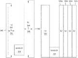
- FIG. 1is a schematic illustration of certain embodiments of a magnetic media drive including a magnetic read head.
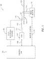
- FIG. 2is a schematic illustration of certain embodiments of a cross sectional side view of a head assembly facing a magnetic storage medium.
- FIGS. 3 A and 3 Bare schematic illustrations of read heads having shields with different heights and thicknesses according to embodiments discussed herein.
- FIGS. 3 C- 3 Eare schematic illustrations of read heads having shields with different layers according to embodiments discussed herein.
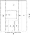
- FIG. 3 Fis a schematic illustration of a read head having a dual free layer sensor according to one embodiment.
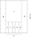
- FIG. 3 Gis a schematic illustration of a read head having a single free layer sensor according to one embodiment.
- FIG. 4is a graph illustrating a linearity improvement according to embodiments discussed herein.
- FIG. 5is a graph illustrating disturbance to a rear hard bias (RHB) structure and transfer curve flip according to embodiments discussed herein.
- RHBrear hard bias
- the present disclosuregenerally relates to a read head of a data storage device.
- the read headincludes a read sensor sandwiched between two shields.
- the shieldscan have different materials as well as a different number of layers.
- the shieldscan be fabricated by different processes and have different heights and thicknesses. The ratio of the thickness to the height for the shields are substantially identical to ensure that the saturation field are substantially identical and balanced.
- FIG. 1is a schematic illustration of certain embodiments of a magnetic media drive 100 including a magnetic write head and a magnetic read head.
- the magnetic media drive 100may be a single drive/device or comprise multiple drives/devices.
- the magnetic media drive 100includes a magnetic recording medium, such as one or more rotatable magnetic disk 112 supported on a spindle 114 and rotated by a drive motor 118 .
- a single disk driveis shown according to one embodiment.
- the magnetic recording on each magnetic disk 112is in the form of any suitable patterns of data tracks, such as annular patterns of concentric data tracks (not shown) on the magnetic disk 112 .
- At least one slider 113is positioned near the magnetic disk 112 .
- Each slider 113supports a head assembly 121 including one or more read/write heads, such as a write head and such as a read head comprising a TMR device.
- the slider 113moves radially in and out over the disk surface 122 so that the head assembly 121 may access different tracks of the magnetic disk 112 where desired data are written or read.
- Each slider 113is attached to an actuator arm 119 by way of a suspension 115 .
- the suspension 115provides a slight spring force which biases the slider 113 toward the disk surface 122 .
- Each actuator arm 119is attached to an actuator 127 .
- the actuator 127 as shown in FIG. 1may be a voice coil motor (VCM).
- the VCMincludes a coil movable within a fixed magnetic field, the direction and speed of the coil movements being controlled by the motor current signals supplied by control unit 129 .
- the rotation of the magnetic disk 112generates an air or gas bearing between the slider 113 and the disk surface 122 which exerts an upward force or lift on the slider 113 .
- the air or gas bearingthus counter-balances the slight spring force of suspension 115 and supports slider 113 off and slightly above the disk surface 122 by a small, substantially constant spacing during normal operation.
- control unit 129The various components of the magnetic media drive 100 are controlled in operation by control signals generated by control unit 129 , such as access control signals and internal clock signals.
- control unit 129comprises logic control circuits, storage means and a microprocessor.
- the control unit 129generates control signals to control various system operations such as drive motor control signals on line 123 and head position and seek control signals on line 128 .
- the control signals on line 128provide the desired current profiles to optimally move and position slider 113 to the desired data track on disk 112 .
- Write and read signalsare communicated to and from the head assembly 121 by way of recording channel 125 .
- Certain embodiments of a magnetic media drive of FIG. 1may further include a plurality of media, or disks, a plurality of actuators, and/or a plurality number of sliders.
- FIG. 2is a schematic illustration of certain embodiments of a cross sectional side view of a head assembly 200 facing the magnetic disk 112 or other magnetic storage medium.
- the head assembly 200may correspond to the head assembly 121 described in FIG. 1 .
- the head assembly 200includes a media facing surface (MFS) 212 facing the magnetic disk 112 .
- MFSmedia facing surface
- the head assembly 200includes a magnetic read head 211 .
- the magnetic read head 211include a sensing element 204 disposed between shields S 1 and S 2 .
- the sensing element 204 and the shields S 1 and S 2having a MFS 212 facing the magnetic disk 112 .
- the sensing element 204is a TMR device sensing the magnetic fields of the recorded bits, such as perpendicular recorded bits or longitudinal recorded bits, in the magnetic disk 112 by a TMR effect.
- the spacing between shields S 1 and S 2is about 17 nm or less.
- the head assembly 200may optionally include a write head 210 .
- the write head 210includes a main pole 220 , a leading shield 206 , and a trailing shield (TS) 240 .
- the main pole 220comprises a magnetic material and serves as a main electrode.
- Each of the main pole 220 , the leading shield 206 , and the trailing shield (TS) 240has a front portion at the MFS.
- the write head 210includes a coil 218 around the main pole 220 that excites the main pole 220 producing a writing magnetic field for affecting a magnetic recording medium of the rotatable magnetic disk 112 .
- the coil 218may be a helical structure or one or more sets of pancake structures.
- the TS 240comprises a magnetic material, serving as a return pole for the main pole 220 .
- the leading shield 206may provide electromagnetic shielding and is separated from the main pole 220 by a leading gap 254 .
- FIGS. 3 A and 3 Bare schematic illustrations of read heads having shields with different heights and thicknesses according to embodiments discussed herein.
- FIGS. 3 C- 3 Eare schematic illustrations of read heads having shields with different layers according to embodiments discussed herein.
- FIG. 3 Fis a schematic illustration of a read head having a dual free layer sensor according to one embodiment.
- FIG. 3 Gis a schematic illustration of a read head having a single fee layer sensor according to one embodiment.
- the read heads of FIG. 3 A- 3 Ginclude a first shield (S 1 ) 302 , a sensor 304 disposed on the S 1 302 , and a second shield (S 2 ) 306 disposed on the sensor 304 .
- the S 1 302has a first thickness and a first height and the S 2 306 has a second thickness and a second height.
- the first thickness 342 of the S 1 302 and the second thickness 344 of the S 2 306each has a thickness of about 0.1 microns to about 2 microns.
- the first height 346 of the S 1 302 and the second height 348 of the S 2 306each has a height of about 10 microns to about 20 microns.
- the previous ranges of values listed for the thickness and the height of the S 1 and the S 2is not intended to be limiting, but to provide an example of possible embodiments.
- the first thicknessis not equal to the second thickness
- the first heightis not equal to the second height.
- the ratio of the first thickness 342 of S 1 302 to the first height 346 of S 1 302is about 2:20 or about 0.1 and the ratio of the second thickness 344 of S 2 306 to the second height 348 of S 2 306 is about 1:10 or about 0.1.
- the ratio of the thickness of S 1 302 to the height of S 1 302is about 1:10 or about 0.1 and the ratio of the thickness of S 2 306 to the height of S 2 306 is about 2:20 or about 0.1.
- the saturation field of each individual shield, S 1 302 and S 2 306is proportional to the product of Ms (i.e., magnetic moment) of the respective shield times the ratio of the respective shield thickness to the respective shield height.
- Msi.e., magnetic moment
- the saturation field of the S 1 and the S 2are substantially identical due to the relationship between the product of the first shield Ms times the ratio of the first thickness 342 to the first height 346 of the S 1 302 and product of the second shield Ms times the ratio of the second thickness 344 to the second height 348 of the S 2 306 .
- the out of plane magnetic fields (seen by reader) from the S 1 302 and the S 2 306are substantially cancelled due to the relationship between the product of the first shield Ms times the ratio of the first thickness 342 to the first height 346 of the S 1 302 and the product of the second shield Ms times the ratio of the second thickness 344 to the second height 348 of the S 2 306 .
- the ratio of the first thickness 342 to the first height 346is about 1:10 or about 0.1.
- the S 1 302 and the S 2 306include materials selected from the group that includes amorphous magnetic alloys, such as nickel (Ni), iron (Fe), cobalt (Co), chromium (Cr), zirconium (Zr), niobium (Nb), hafnium (Hf), and combinations thereof.
- the Ms of the shielding materialis the same in S 1 302 and S 2 306 .
- the Ms of the shielding materialhas over 100% difference in magnitude as between that of S 1 and S 2 .
- the S 1 302 and the S 2 306may each be formed through a first method or through different methods, such as a first method to form S 1 302 and a second method to form S 2 306 . Methods to form the S 1 302 and the S 2 306 include chemical vapor deposition (CVD), atomic layer deposition (ALD), physical vapor deposition (PVD), electroplating, and the other methods appropriate to forming a shield.
- CVDchemical vapor de
- FIG. 3 Cis a schematic illustration of a read head including a S 1 302 , a sensor 304 disposed on the S 1 302 , and a plurality of S 2 layers 306 a - 306 n , with n representing 4 or more, where a first S 2 layer 306 a is disposed on the sensor 304 and each subsequent S 2 layer 306 b - 306 n is disposed on the previous S 2 layer 306 b - 306 n .
- the second S 2 layer 306 bis disposed on the first S 2 layer 306 a
- the third S 2 layer 306 cis disposed on the second S 2 layer 306 b , and so-forth.
- the S 1 302may be formed by a first method that includes a first material. Furthermore, each of the one or more S 2 layers 306 a - 306 n may be formed by a second method that is different from the first method of the S 1 302 that includes a second material that is different from the first material.
- the materials and methods of forming each shield of a read headinclude the previously listed methods and materials applicable to the shield of a read head. Furthermore, each layer of the one or more S 2 layers 306 a - 306 n may comprise identical or different materials and be formed by identical or different methods.
- FIG. 3 Dis a schematic illustration of a read head including a plurality of S 1 302 a - 302 n , with n representing 4 or more, a sensor 304 disposed on the plurality of S 1 302 a - 302 n , and a S 2 layer 306 , where the last S 1 layer 302 n is disposed adjacent to and in contact with the sensor 304 .
- the second S 1 layer 302 bis disposed on the first S 1 layer 302 a
- the third S 1 layer 302 cis disposed on the second S 1 layer 302 b
- the S 2 306may be formed by a first method that includes a first material.
- each of the one or more S 1 layers 302 a - 302 nmay be formed by a second method that is different from the first method of the S 2 306 that includes a second material that is different from the first material.
- the materials and methods of forming each shield of a read headinclude the previously listed methods and materials applicable to the shield of a read head.
- each layer of the one or more S 1 layers 302 a - 302 nmay comprise identical or different materials and be formed by identical or different methods.
- FIG. 3 Eis a schematic illustration of a read head including a plurality of S 1 302 a - 302 n , with n representing 4 or more, a sensor 304 disposed on the plurality of S 1 302 a - 302 n , and a plurality of S 2 306 a - 306 n (with n representing 4 or more) disposed on the sensor 304 .
- the second S 1 layer 302 bis disposed on the first S 1 layer 302 a
- the third S 1 layer 302 cis disposed on the second S 1 layer 302 b , and so forth. Additionally as shown in FIG.
- a first S 2 layer 306 ais disposed on the sensor 304 and each subsequent S 2 layer 306 b - 306 n is disposed on the previous S 2 layer 306 b - 306 n such that the second S 2 layer 306 b is disposed on the first S 2 layer 306 a , the third S 2 layer 306 c is disposed on the second S 2 layer 306 b , and so forth.
- Each of the one or more S 1 layers 302 a - 302 nmay be formed by a first method that is different from the second method of forming the one or more S 2 layers 306 a - 306 n .
- the materials for the one or more S 1 layers 302 a - 302 nmay comprise a first material that is different from a second material that comprises the one or more S 2 layers 306 a - 306 n .
- the different layers of S 1 302 a - 302 nmay comprise different materials.
- the different layers of S 2 306 a - 306 nmay comprise different materials.
- the materials and methods of forming each shield of a read headinclude the previously listed methods and materials applicable to the shield of a read head.
- each layer of the one or more S 1 layers 302 a - 302 n and the one or more S 2 layers 306 a - 306 nmay comprise identical or different materials and be formed by identical or different methods.
- FIG. 3 Fis a schematic illustration of a read head, according to one embodiment, including a first shield (S 1 ) 302 , a dual free layer (DFL) sensor 304 , a second shield (S 2 ) 306 , an insulation 320 , a rear hard bias (RHB) 318 , and a nonmagnetic layer 322 .
- the sensor 304includes a seed layer 308 , a first free layer (FL) 310 , a barrier layer (such as MgO) 312 , a second FL 314 , and a cap layer 316 . Because the sensor 304 includes two FLs 310 , 314 , the sensor 304 may be considered a dual free layer (DFL) sensor.
- the sensor 304may be a magnetic tunnel junction (MTJ) stack and may be formed using PVD sputtering, IBD, and other well-known deposition methods.
- the seed layer 308includes a material selected from the group that includes tantalum (Ta), tungsten (W), Ru, Cr, Co, Ti, Hf, and combinations thereof.
- the cap layer 316may be Ta, Ru, Cr, Ti, Hf or any other suitable cap material.
- the insulation 320may be MgO, aluminum oxide (AlOx), SiN or any other suitable insulation material. Free layers may each include Ni, Fe, Co, boron, Hf or combinations thereof.
- the rear hard bias (RHB) 318may include cobalt platinum (CoPt) or CoCrPt with high coercivity sitting on an appropriate seed layer to generate a magnetic field that acts on the sensor 304 . Furthermore, a nonmagnetic layer 322 separates the RHB 318 from the S 2 306 , such that the RHB 318 is not in contact with the S 2 306 .
- FIG. 3 Gis a schematic illustration of a read head having a single free layer sensor according to one embodiment.
- the read headincludes a first shield (S 1 ) 302 , a sensor 380 , a second shield (S 2 ) 306 , and an insulation 320 .
- the sensor 380includes a seed layer 382 , a fixed magnetic layer 384 , a barrier layer 386 , a free layer (FL) 388 , and a cap layer 390 .
- the sensor 380is a magnetic tunnel junction (MTJ) stack and may be formed using PVD sputtering, IBD, and other well-known deposition methods.
- MTJmagnetic tunnel junction
- the seed layer 382includes a material selected from the group that includes tantalum (Ta), tungsten (W), Ru, Cr, Co, Ti, and combinations thereof.
- the cap layer 390may be Ta, Ru, Cr, Ti, Hf or any other suitable cap material.
- the barrier layer 386may be MgO, aluminum oxide (AlOx) or any other suitable insulation material.
- the free layer 388 and the fixed layer 384include Ni, Fe, Co, boron, Hf or combinations thereof.
- FIG. 4is a graph illustrating a reader linearity improvement according to embodiments discussed herein.
- the applied field, H (Oe)is graphed on the x-axis and the net out-of-plane field from shield, seen by sensor Hz (Oe), is graphed on the y-axis.
- the solid lineis the base case where both S 1 and S 2 have the same Ms, where the ratio of the thickness to the height of the first shield, such as S 1 302 , and ratio of the thickness to the height of the second shield, such as S 2 306 , are not substantially identical.
- the dotted line casehas the Ms of the first shield times the ratio of the thickness to the height of the first shield identical to the Ms of the second shield times the ratio of the thickness to the height of the second shield. Further, the first shield height is equal to the second shield height in the dotted line case. Because the ratio of the thickness to the height of each shield is substantially identical and because the Ms are the same for both shields, the out-of-plane fields are effectively canceled (e.g., closer to 0 on the y-axis), resulting in a more linearized and improved sensor transfer curve and a smaller asymmetrical standard deviation.
- FIG. 5is a graph illustrating disturbance to a rear hard bias (RHB) structure in the case where a DFL sensor is implemented and transfer curve flip according to embodiments discussed herein.
- the transverse field, H(Oe)is graphed on the x-axis and the out-of-plane field, Hz (Oe), is graphed on the y-axis.
- the solid lineis the base case, where the ratio of the thickness to the height of the first shield, such as S 1 302 , and ratio of the thickness to the height of the second shield, such as S 2 306 , are not substantially identical.
- the dotted line casehas the Ms of the first shield times the ratio of the thickness to the height of the first shield substantially identical to the Ms of the second shield times the ratio of the thickness to the height of the second shield. Moreover, the first shield height is equal to the second shield height of the dotted line case.
- a typical DFL designusually includes a RHB, such as RHB 318 of FIG. 3 F .
- the un-cancelled out-of-plane fields generated by the opposing shieldsmay have a negative effect (e.g., a polarity flip), if they are closer or larger than the coercivity of the RHB, and may: (1) disturb magnetization of RHB, and (2) in an extreme case, flip the RHB direction, resulting in polarity flip of sensor transfer curve.
- a negative effecte.g., a polarity flip
- the out-of-plane fieldsare effectively cancelled or minimized (e.g., closer to 0 on the y-axis), resulting in little or no impact on RHB and no polarity flip of the sensor and improved sensor performance.
- the magnetic recording head discussed hereinis applicable to a data storage device such as a hard disk drive (HDD) as well as a tape drive such as a tape embedded drive (TED) or an insertable tape media drive.
- a data storage devicesuch as a hard disk drive (HDD)
- TEDtape embedded drive
- An example TEDis described in co-pending United States patent application entitled “Tape Embedded Drive”, application Ser. No. 16/365,034, filed on Mar. 31, 2019 and assigned to the same assignee of the instant application, which is incorporated by reference herein.
- any reference in the detailed description to a HDD or tape driveis merely for exemplification purposes and is not intended to limit the disclosure unless explicitly claimed.
- reference to or claims directed to magnetic recording devicesare intended to include both HDD and tape drive unless HDD or tape drive devices are explicitly claimed.
- a magnetic read headcomprises: a first shield, the first shield having a first thickness and a first height; a sensor disposed on the first shield; and a second shield disposed on the sensor, wherein the second shield has a second thickness and a second height, wherein the first thickness and the second thickness are different, and wherein a ratio of the first thickness to the first height is substantially identical to a ratio of the second thickness to the second height.
- Both the first thickness and the second thicknessare between about 0.5 microns and about 2 microns.
- Both the first height and the second heightare between about 10 microns and about 20 microns.
- the sensorcomprises a dual free layer sensor.
- the first shield and the second shieldhave substantially identical Ms.
- the first shield and the second shieldhave different values for Ms, and wherein Ms for the first shield times the first thickness divided by the first height equals Ms for the second shield times the second thickness divided by the second height.
- a magnetic media drivecomprising the magnetic read head is also disclosed.
- a magnetic read headcomprises: a first shield, wherein the first shield comprises one or more first shield layers; a sensor disposed on the first shield; and a second shield disposed on the first shield, wherein the second shield comprises one or more second shield layers, wherein one or more of the first shield and the second shield comprises a plurality of layers, and wherein the first shield and the second shield have substantially identical magnetic saturation fields.
- the sensoris a single free layer sensor. At least one layer of the plurality of layers of the second shield is formed by a method that is different from a method used to form the first shield.
- the first shieldcomprises a first material, wherein the second shield comprises a second material that is different from the first material.
- the first shieldhas a first thickness and first height, wherein the second shield has a second thickness and a second height, and wherein the first height is different from the second height.
- a ratio of the first thickness to the first heightis substantially identical to a ratio of the second thickness to the second height.
- the magnetic read headfurther comprises a magnetic hard bias structure disposed between the first shield and the second shield.
- a magnetic media drive comprising the magnetic read headis also disclosed.
- a magnetic read headcomprises: a first shield comprising a single, first layer, wherein the first layer has a first thickness and a first height; a sensor disposed on the first shield, wherein the sensor is a dual free layer sensor; and a second shield disposed on the sensor, wherein the second shield comprises a plurality of layers, wherein the plurality of layers has a second thickness and a second height, and wherein the first thickness is different from the second thickness, and wherein a ratio of the first thickness to the first height is substantially identical to a ratio of the second thickness to the second height. Out of plane magnetic fields from the first shield and the second shield are substantially cancelled. A magnetic saturation field of the first shield is substantially identical to a magnetic saturation field of the second shield.
- the sensoris a single free layer sensor. When the sensor is a dual free layer sensor, the magnetic read head further comprises a magnetic hard bias structure disposed behind the sensor and between the first shield and the second shield.
- a magnetic media drivecomprising the magnetic read head is also disclosed.
- shields having different materials, different number of layers, fabricated by different processes, and or having different heights and thicknesseskeeping the ratio of the thickness to the height for the shields to be substantially identical ensures that the saturation field are substantially identical and balanced.
Landscapes
- Engineering & Computer Science (AREA)
- Manufacturing & Machinery (AREA)
- Magnetic Heads (AREA)
Abstract
Description
Claims (20)
Priority Applications (1)
| Application Number | Priority Date | Filing Date | Title |
|---|---|---|---|
| US17/448,167US11557317B2 (en) | 2020-06-23 | 2021-09-20 | Read head sensor with balanced shield design |
Applications Claiming Priority (2)
| Application Number | Priority Date | Filing Date | Title |
|---|---|---|---|
| US16/909,785US11170807B1 (en) | 2020-06-23 | 2020-06-23 | Read head sensor with balanced shield design |
| US17/448,167US11557317B2 (en) | 2020-06-23 | 2021-09-20 | Read head sensor with balanced shield design |
Related Parent Applications (1)
| Application Number | Title | Priority Date | Filing Date |
|---|---|---|---|
| US16/909,785DivisionUS11170807B1 (en) | 2020-06-23 | 2020-06-23 | Read head sensor with balanced shield design |
Publications (2)
| Publication Number | Publication Date |
|---|---|
| US20220028418A1 US20220028418A1 (en) | 2022-01-27 |
| US11557317B2true US11557317B2 (en) | 2023-01-17 |
Family
ID=78467406
Family Applications (2)
| Application Number | Title | Priority Date | Filing Date |
|---|---|---|---|
| US16/909,785Active2040-11-07US11170807B1 (en) | 2020-06-23 | 2020-06-23 | Read head sensor with balanced shield design |
| US17/448,167ActiveUS11557317B2 (en) | 2020-06-23 | 2021-09-20 | Read head sensor with balanced shield design |
Family Applications Before (1)
| Application Number | Title | Priority Date | Filing Date |
|---|---|---|---|
| US16/909,785Active2040-11-07US11170807B1 (en) | 2020-06-23 | 2020-06-23 | Read head sensor with balanced shield design |
Country Status (3)
| Country | Link |
|---|---|
| US (2) | US11170807B1 (en) |
| CN (1) | CN113838483B (en) |
| DE (1) | DE102021106148A1 (en) |
Families Citing this family (2)
| Publication number | Priority date | Publication date | Assignee | Title |
|---|---|---|---|---|
| US11170807B1 (en)* | 2020-06-23 | 2021-11-09 | Western Digital Technologies, Inc. | Read head sensor with balanced shield design |
| US20250140285A1 (en)* | 2023-10-27 | 2025-05-01 | Western Digital Technologies, Inc. | Rear Soft Bias Dual Free Layer Sensor With Patterned Decoupling Layer |
Citations (31)
| Publication number | Priority date | Publication date | Assignee | Title |
|---|---|---|---|---|
| US4918554A (en)* | 1988-09-27 | 1990-04-17 | International Business Machines Corporation | Process for making a shielded magnetoresistive sensor |
| JP2927285B1 (en) | 1998-01-26 | 1999-07-28 | 日本電気株式会社 | Magnetoresistive head |
| US6118621A (en)* | 1995-06-22 | 2000-09-12 | Kabushiki Kaisha Toshiba | Magnetoresistance effect head having a pair of protrusions, steps or depressions between the detecting and nondetecting areas for improved off-track characteristics |
| US6292334B1 (en)* | 1998-07-31 | 2001-09-18 | Alps Electric Co., Ltd. | Thin film magnetic head comprising shield layer having stabilized magnetic domain structure |
| JP2002170210A (en) | 2000-11-28 | 2002-06-14 | Hitachi Ltd | Magnetoresistive magnetic head, method for measuring electromagnetic conversion characteristics thereof, and apparatus for measuring electromagnetic conversion characteristics |
| US20040156148A1 (en)* | 2003-02-11 | 2004-08-12 | Chang Thomas Young | Magnetic recording head with a side shield structure for controlling side reading of thin film read sensor |
| US20050201018A1 (en)* | 2004-03-08 | 2005-09-15 | Tdk Corporation | Magnetic head, head suspension assembly and magnetic disk apparatus |
| JP2007004985A (en) | 2006-10-16 | 2007-01-11 | Hitachi Global Storage Technologies Netherlands Bv | Magnetic head and magnetic recording / reproducing apparatus equipped with the same |
| US20070201166A1 (en)* | 2006-02-24 | 2007-08-30 | Gill Hardayal Harry S | Lead/shield structure for read head sensors |
| US7656619B1 (en) | 2003-06-05 | 2010-02-02 | Seagate Technology Llc | Magnetic head sliders for disk drives having a heating element and pedestal in thick undercoat layer |
| US20100027168A1 (en)* | 2008-07-29 | 2010-02-04 | Tdk Corporation | Thin film magnetic head having a pair of magnetic layers whose magnetization is controlled by shield layers |
| US20100067148A1 (en)* | 2008-09-16 | 2010-03-18 | Tdk Corporation | Thin film magnetic head having a pair of magnetic layers whose magnetization is controlled by shield layers |
| US20100103562A1 (en)* | 2008-10-27 | 2010-04-29 | Tdk Corporation | Magnetoresistive element including a pair of ferromagnetic layers coupled to a pair of shield layers |
| US20100103563A1 (en)* | 2008-10-29 | 2010-04-29 | Tdk Corporation | Magnetoresistive element including a pair of ferromagnetic layers coupled to a pair of shield layers |
| US20100149689A1 (en)* | 2008-12-11 | 2010-06-17 | Tdk Corporation | Thin film magnetic head having a pair of magnetic layers whose magnetization is controlled by shield layer including amorphous layer |
| US20100163519A1 (en)* | 2008-12-30 | 2010-07-01 | Tdk Corporation | Method for manufacturing CPP-type magnetoresistance effect element |
| US7782574B1 (en) | 2005-04-11 | 2010-08-24 | Seagate Technology Llc | Magnetic heads disk drives and methods with thicker read shield structures for reduced stray field sensitivity |
| US20110069417A1 (en)* | 2009-09-22 | 2011-03-24 | Tdk Corporation | Magnetoresistive effect element in CPP structure and magnetic disk device |
| US20110279923A1 (en)* | 2010-05-17 | 2011-11-17 | Tdk Corporation | Magnetoresistive element having a pair of side shields |
| US20110310513A1 (en)* | 2010-06-16 | 2011-12-22 | Seagate Technology Llc | Auxiliary magnetoresistive shield |
| US20130149559A1 (en) | 2011-04-25 | 2013-06-13 | Seagate Technology Llc | Magnetic Element with Dual Magnetic Moments |
| US20140120374A1 (en)* | 2012-11-01 | 2014-05-01 | Seagate Technology Llc | Magnetic devices having shields including a nickel alloy |
| US20140218821A1 (en)* | 2013-02-07 | 2014-08-07 | Seagate Technology Llc | Data reader with magnetic seed lamination |
| US9293160B1 (en)* | 2015-02-06 | 2016-03-22 | HGST Netherlands B.V. | Magnetic stabilization and scissor design for anomalous hall effect magnetic read sensor |
| US9472216B1 (en) | 2015-09-23 | 2016-10-18 | Western Digital (Fremont), Llc | Differential dual free layer magnetic reader |
| US20170154642A1 (en) | 2015-11-30 | 2017-06-01 | International Business Machines Corporation | Shorting-resistant current perpendicular to plane sensors |
| US20170256276A1 (en) | 2016-03-03 | 2017-09-07 | Tdk Corporation | Multi reader head having a varying gap layer laminated between readers |
| US20180144768A1 (en) | 2016-11-21 | 2018-05-24 | Headway Technologies, Inc. | Write Head Designs with Sandwich Trailing Shield (STS) for High Data Rate Perpendicular Recording |
| US10074387B1 (en)* | 2014-12-21 | 2018-09-11 | Western Digital (Fremont), Llc | Method and system for providing a read transducer having symmetric antiferromagnetically coupled shields |
| US10991390B2 (en) | 2019-02-08 | 2021-04-27 | Western Digital Technologies, Inc. | Head assembly with suspension system for a tape embedded drive |
| US11170807B1 (en)* | 2020-06-23 | 2021-11-09 | Western Digital Technologies, Inc. | Read head sensor with balanced shield design |
Family Cites Families (4)
| Publication number | Priority date | Publication date | Assignee | Title |
|---|---|---|---|---|
| US6888705B2 (en)* | 2002-01-18 | 2005-05-03 | Hitachi Global Storage Technologies Netherlands B.V. | High linear density tunnel junction flux guide read head with in-stack longitudinal bias stack (LBS) |
| US7038890B2 (en)* | 2003-07-29 | 2006-05-02 | Hitachi Global Storage Technologies Netherlands B.V. | Current perpendicular to the planes (CPP) sensor with a highly conductive cap structure |
| US7551396B2 (en)* | 2005-04-27 | 2009-06-23 | Hitachi Global Storage Technologies Netherlands B.V. | Perpendicular magnetic write head having a studded trailing shield compatible with read/write offset |
| US8675315B2 (en)* | 2011-07-29 | 2014-03-18 | Seagate Technology Llc | Magnetic sensor with anisotropic liner |
- 2020
- 2020-06-23USUS16/909,785patent/US11170807B1/enactiveActive
- 2021
- 2021-03-09CNCN202110254477.2Apatent/CN113838483B/enactiveActive
- 2021-03-12DEDE102021106148.2Apatent/DE102021106148A1/enactivePending
- 2021-09-20USUS17/448,167patent/US11557317B2/enactiveActive
Patent Citations (31)
| Publication number | Priority date | Publication date | Assignee | Title |
|---|---|---|---|---|
| US4918554A (en)* | 1988-09-27 | 1990-04-17 | International Business Machines Corporation | Process for making a shielded magnetoresistive sensor |
| US6118621A (en)* | 1995-06-22 | 2000-09-12 | Kabushiki Kaisha Toshiba | Magnetoresistance effect head having a pair of protrusions, steps or depressions between the detecting and nondetecting areas for improved off-track characteristics |
| JP2927285B1 (en) | 1998-01-26 | 1999-07-28 | 日本電気株式会社 | Magnetoresistive head |
| US6292334B1 (en)* | 1998-07-31 | 2001-09-18 | Alps Electric Co., Ltd. | Thin film magnetic head comprising shield layer having stabilized magnetic domain structure |
| JP2002170210A (en) | 2000-11-28 | 2002-06-14 | Hitachi Ltd | Magnetoresistive magnetic head, method for measuring electromagnetic conversion characteristics thereof, and apparatus for measuring electromagnetic conversion characteristics |
| US20040156148A1 (en)* | 2003-02-11 | 2004-08-12 | Chang Thomas Young | Magnetic recording head with a side shield structure for controlling side reading of thin film read sensor |
| US7656619B1 (en) | 2003-06-05 | 2010-02-02 | Seagate Technology Llc | Magnetic head sliders for disk drives having a heating element and pedestal in thick undercoat layer |
| US20050201018A1 (en)* | 2004-03-08 | 2005-09-15 | Tdk Corporation | Magnetic head, head suspension assembly and magnetic disk apparatus |
| US7782574B1 (en) | 2005-04-11 | 2010-08-24 | Seagate Technology Llc | Magnetic heads disk drives and methods with thicker read shield structures for reduced stray field sensitivity |
| US20070201166A1 (en)* | 2006-02-24 | 2007-08-30 | Gill Hardayal Harry S | Lead/shield structure for read head sensors |
| JP2007004985A (en) | 2006-10-16 | 2007-01-11 | Hitachi Global Storage Technologies Netherlands Bv | Magnetic head and magnetic recording / reproducing apparatus equipped with the same |
| US20100027168A1 (en)* | 2008-07-29 | 2010-02-04 | Tdk Corporation | Thin film magnetic head having a pair of magnetic layers whose magnetization is controlled by shield layers |
| US20100067148A1 (en)* | 2008-09-16 | 2010-03-18 | Tdk Corporation | Thin film magnetic head having a pair of magnetic layers whose magnetization is controlled by shield layers |
| US20100103562A1 (en)* | 2008-10-27 | 2010-04-29 | Tdk Corporation | Magnetoresistive element including a pair of ferromagnetic layers coupled to a pair of shield layers |
| US20100103563A1 (en)* | 2008-10-29 | 2010-04-29 | Tdk Corporation | Magnetoresistive element including a pair of ferromagnetic layers coupled to a pair of shield layers |
| US20100149689A1 (en)* | 2008-12-11 | 2010-06-17 | Tdk Corporation | Thin film magnetic head having a pair of magnetic layers whose magnetization is controlled by shield layer including amorphous layer |
| US20100163519A1 (en)* | 2008-12-30 | 2010-07-01 | Tdk Corporation | Method for manufacturing CPP-type magnetoresistance effect element |
| US20110069417A1 (en)* | 2009-09-22 | 2011-03-24 | Tdk Corporation | Magnetoresistive effect element in CPP structure and magnetic disk device |
| US20110279923A1 (en)* | 2010-05-17 | 2011-11-17 | Tdk Corporation | Magnetoresistive element having a pair of side shields |
| US20110310513A1 (en)* | 2010-06-16 | 2011-12-22 | Seagate Technology Llc | Auxiliary magnetoresistive shield |
| US20130149559A1 (en) | 2011-04-25 | 2013-06-13 | Seagate Technology Llc | Magnetic Element with Dual Magnetic Moments |
| US20140120374A1 (en)* | 2012-11-01 | 2014-05-01 | Seagate Technology Llc | Magnetic devices having shields including a nickel alloy |
| US20140218821A1 (en)* | 2013-02-07 | 2014-08-07 | Seagate Technology Llc | Data reader with magnetic seed lamination |
| US10074387B1 (en)* | 2014-12-21 | 2018-09-11 | Western Digital (Fremont), Llc | Method and system for providing a read transducer having symmetric antiferromagnetically coupled shields |
| US9293160B1 (en)* | 2015-02-06 | 2016-03-22 | HGST Netherlands B.V. | Magnetic stabilization and scissor design for anomalous hall effect magnetic read sensor |
| US9472216B1 (en) | 2015-09-23 | 2016-10-18 | Western Digital (Fremont), Llc | Differential dual free layer magnetic reader |
| US20170154642A1 (en) | 2015-11-30 | 2017-06-01 | International Business Machines Corporation | Shorting-resistant current perpendicular to plane sensors |
| US20170256276A1 (en) | 2016-03-03 | 2017-09-07 | Tdk Corporation | Multi reader head having a varying gap layer laminated between readers |
| US20180144768A1 (en) | 2016-11-21 | 2018-05-24 | Headway Technologies, Inc. | Write Head Designs with Sandwich Trailing Shield (STS) for High Data Rate Perpendicular Recording |
| US10991390B2 (en) | 2019-02-08 | 2021-04-27 | Western Digital Technologies, Inc. | Head assembly with suspension system for a tape embedded drive |
| US11170807B1 (en)* | 2020-06-23 | 2021-11-09 | Western Digital Technologies, Inc. | Read head sensor with balanced shield design |
Also Published As
| Publication number | Publication date |
|---|---|
| US11170807B1 (en) | 2021-11-09 |
| CN113838483B (en) | 2023-06-20 |
| CN113838483A (en) | 2021-12-24 |
| DE102021106148A1 (en) | 2021-12-23 |
| US20220028418A1 (en) | 2022-01-27 |
Similar Documents
| Publication | Publication Date | Title |
|---|---|---|
| US8336194B2 (en) | Method of fabricating a tunneling magnetoresistive (TMR) reader | |
| US7130167B2 (en) | Magnetoresistive sensor having improved synthetic free layer | |
| US8270125B2 (en) | Tunnel junction magnetoresistive sensor having a near zero magnetostriction free layer | |
| US7633711B2 (en) | Magnetic write head with helical coil structure using multiple materials | |
| US11170808B1 (en) | Dual free layer reader head with magnetic seed layer decoupled from shield | |
| US11514935B1 (en) | Magnetic read sensors having stabilized upper readers, and related methods | |
| US20110026169A1 (en) | Dual cpp gmr head using a scissor sensor | |
| US11430470B2 (en) | Magnetic read sensors and related methods having a rear hard bias and no AFM layer | |
| US10950260B1 (en) | Magnetoresistive sensor with improved magnetic properties and magnetostriction control | |
| US10891976B1 (en) | Areal density capability improvement with a main pole skin | |
| US11557317B2 (en) | Read head sensor with balanced shield design | |
| US20240233762A1 (en) | Magnetic Read Sensors Having Reduced Signal Imbalance | |
| US11776725B2 (en) | Magnetic elements of amorphous based dual free layer structures and recording devices using such elements | |
| US7408749B2 (en) | CPP GMR/TMR structure providing higher dR | |
| US20060023376A1 (en) | Trilayer SAF with current confining layer | |
| US7268982B2 (en) | Current perpendicular to plane (CPP) GMR structure having vanadium doped, AP coupled, multi-layered pinned structure | |
| US7436629B2 (en) | Laminated magnetic structure for use in a perpendicular magnetic write head | |
| US7256972B2 (en) | CPP sensor with improved pinning strength longitudinal bias structure | |
| US8351163B2 (en) | Tunneling magnetoresistance read head having a cofe interface layer and methods for producing the same | |
| US7382590B2 (en) | MR sensor and thin film media having alloyed Ru antiparallel spacer layer for enhanced antiparallel exchange coupling | |
| US20250140285A1 (en) | Rear Soft Bias Dual Free Layer Sensor With Patterned Decoupling Layer | |
| CN114664330B (en) | Dual free layer reader head with magnetic seed layer decoupled from shield | |
| US20250218457A1 (en) | Magnetic Heads Having Low Magnetic Coercivity (HC) And High Saturated Magnetic Flux Density (BS) In Ferromagnetic (FM) Layer(s) Or Shield(s) With Minimized Saturation | |
| US20250218456A1 (en) | Magnetic Heads Having Low Magnetic Coercivity (Hc) and High Saturated Magnetic Flux Density (Bs) in Ferromagnetic (FM) Layer(s) or Shield(s) With Minimized Saturation | |
| US8518717B2 (en) | Method for junction isolation to reduce junction damage for a TMR sensor |
Legal Events
| Date | Code | Title | Description |
|---|---|---|---|
| AS | Assignment | Owner name:WESTERN DIGITAL TECHNOLOGIES, INC., CALIFORNIA Free format text:ASSIGNMENT OF ASSIGNORS INTEREST;ASSIGNORS:LIU, XIAOYONG;BAIAO DE ALBUQUERQUE, GONCALO;MAURI, DANIELE;AND OTHERS;SIGNING DATES FROM 20200610 TO 20200612;REEL/FRAME:057536/0335 | |
| FEPP | Fee payment procedure | Free format text:ENTITY STATUS SET TO UNDISCOUNTED (ORIGINAL EVENT CODE: BIG.); ENTITY STATUS OF PATENT OWNER: LARGE ENTITY | |
| AS | Assignment | Owner name:JPMORGAN CHASE BANK, N.A., AS AGENT, ILLINOIS Free format text:SECURITY INTEREST;ASSIGNOR:WESTERN DIGITAL TECHNOLOGIES, INC.;REEL/FRAME:058426/0815 Effective date:20211104 | |
| AS | Assignment | Owner name:WESTERN DIGITAL TECHNOLOGIES, INC., CALIFORNIA Free format text:RELEASE OF SECURITY INTEREST AT REEL 058426 FRAME 0815;ASSIGNOR:JPMORGAN CHASE BANK, N.A.;REEL/FRAME:058965/0679 Effective date:20220203 | |
| STPP | Information on status: patent application and granting procedure in general | Free format text:NON FINAL ACTION MAILED | |
| STPP | Information on status: patent application and granting procedure in general | Free format text:RESPONSE TO NON-FINAL OFFICE ACTION ENTERED AND FORWARDED TO EXAMINER | |
| STPP | Information on status: patent application and granting procedure in general | Free format text:FINAL REJECTION MAILED | |
| STPP | Information on status: patent application and granting procedure in general | Free format text:RESPONSE AFTER FINAL ACTION FORWARDED TO EXAMINER | |
| STPP | Information on status: patent application and granting procedure in general | Free format text:NOTICE OF ALLOWANCE MAILED -- APPLICATION RECEIVED IN OFFICE OF PUBLICATIONS | |
| STPP | Information on status: patent application and granting procedure in general | Free format text:PUBLICATIONS -- ISSUE FEE PAYMENT RECEIVED | |
| STPP | Information on status: patent application and granting procedure in general | Free format text:PUBLICATIONS -- ISSUE FEE PAYMENT VERIFIED | |
| STCF | Information on status: patent grant | Free format text:PATENTED CASE | |
| AS | Assignment | Owner name:JPMORGAN CHASE BANK, N.A., ILLINOIS Free format text:PATENT COLLATERAL AGREEMENT - A&R LOAN AGREEMENT;ASSIGNOR:WESTERN DIGITAL TECHNOLOGIES, INC.;REEL/FRAME:064715/0001 Effective date:20230818 Owner name:JPMORGAN CHASE BANK, N.A., ILLINOIS Free format text:PATENT COLLATERAL AGREEMENT - DDTL LOAN AGREEMENT;ASSIGNOR:WESTERN DIGITAL TECHNOLOGIES, INC.;REEL/FRAME:067045/0156 Effective date:20230818 |