US11554020B2 - Expandable implant with pivoting control assembly - Google Patents
Expandable implant with pivoting control assemblyDownload PDFInfo
- Publication number
- US11554020B2 US11554020B2US17/014,546US202017014546AUS11554020B2US 11554020 B2US11554020 B2US 11554020B2US 202017014546 AUS202017014546 AUS 202017014546AUS 11554020 B2US11554020 B2US 11554020B2
- Authority
- US
- United States
- Prior art keywords
- control
- support
- pivot
- implant
- control shaft
- Prior art date
- Legal status (The legal status is an assumption and is not a legal conclusion. Google has not performed a legal analysis and makes no representation as to the accuracy of the status listed.)
- Active
Links
Images


Classifications
- A—HUMAN NECESSITIES
- A61—MEDICAL OR VETERINARY SCIENCE; HYGIENE
- A61F—FILTERS IMPLANTABLE INTO BLOOD VESSELS; PROSTHESES; DEVICES PROVIDING PATENCY TO, OR PREVENTING COLLAPSING OF, TUBULAR STRUCTURES OF THE BODY, e.g. STENTS; ORTHOPAEDIC, NURSING OR CONTRACEPTIVE DEVICES; FOMENTATION; TREATMENT OR PROTECTION OF EYES OR EARS; BANDAGES, DRESSINGS OR ABSORBENT PADS; FIRST-AID KITS
- A61F2/00—Filters implantable into blood vessels; Prostheses, i.e. artificial substitutes or replacements for parts of the body; Appliances for connecting them with the body; Devices providing patency to, or preventing collapsing of, tubular structures of the body, e.g. stents
- A61F2/02—Prostheses implantable into the body
- A61F2/30—Joints
- A61F2/44—Joints for the spine, e.g. vertebrae, spinal discs
- A61F2/442—Intervertebral or spinal discs, e.g. resilient
- A—HUMAN NECESSITIES
- A61—MEDICAL OR VETERINARY SCIENCE; HYGIENE
- A61F—FILTERS IMPLANTABLE INTO BLOOD VESSELS; PROSTHESES; DEVICES PROVIDING PATENCY TO, OR PREVENTING COLLAPSING OF, TUBULAR STRUCTURES OF THE BODY, e.g. STENTS; ORTHOPAEDIC, NURSING OR CONTRACEPTIVE DEVICES; FOMENTATION; TREATMENT OR PROTECTION OF EYES OR EARS; BANDAGES, DRESSINGS OR ABSORBENT PADS; FIRST-AID KITS
- A61F2/00—Filters implantable into blood vessels; Prostheses, i.e. artificial substitutes or replacements for parts of the body; Appliances for connecting them with the body; Devices providing patency to, or preventing collapsing of, tubular structures of the body, e.g. stents
- A61F2/02—Prostheses implantable into the body
- A61F2/30—Joints
- A61F2/44—Joints for the spine, e.g. vertebrae, spinal discs
- A61F2/4455—Joints for the spine, e.g. vertebrae, spinal discs for the fusion of spinal bodies, e.g. intervertebral fusion of adjacent spinal bodies, e.g. fusion cages
- A—HUMAN NECESSITIES
- A61—MEDICAL OR VETERINARY SCIENCE; HYGIENE
- A61F—FILTERS IMPLANTABLE INTO BLOOD VESSELS; PROSTHESES; DEVICES PROVIDING PATENCY TO, OR PREVENTING COLLAPSING OF, TUBULAR STRUCTURES OF THE BODY, e.g. STENTS; ORTHOPAEDIC, NURSING OR CONTRACEPTIVE DEVICES; FOMENTATION; TREATMENT OR PROTECTION OF EYES OR EARS; BANDAGES, DRESSINGS OR ABSORBENT PADS; FIRST-AID KITS
- A61F2/00—Filters implantable into blood vessels; Prostheses, i.e. artificial substitutes or replacements for parts of the body; Appliances for connecting them with the body; Devices providing patency to, or preventing collapsing of, tubular structures of the body, e.g. stents
- A61F2/02—Prostheses implantable into the body
- A61F2/30—Joints
- A61F2/30721—Accessories
- A61F2/30744—End caps, e.g. for closing an endoprosthetic cavity
- A—HUMAN NECESSITIES
- A61—MEDICAL OR VETERINARY SCIENCE; HYGIENE
- A61F—FILTERS IMPLANTABLE INTO BLOOD VESSELS; PROSTHESES; DEVICES PROVIDING PATENCY TO, OR PREVENTING COLLAPSING OF, TUBULAR STRUCTURES OF THE BODY, e.g. STENTS; ORTHOPAEDIC, NURSING OR CONTRACEPTIVE DEVICES; FOMENTATION; TREATMENT OR PROTECTION OF EYES OR EARS; BANDAGES, DRESSINGS OR ABSORBENT PADS; FIRST-AID KITS
- A61F2/00—Filters implantable into blood vessels; Prostheses, i.e. artificial substitutes or replacements for parts of the body; Appliances for connecting them with the body; Devices providing patency to, or preventing collapsing of, tubular structures of the body, e.g. stents
- A61F2/02—Prostheses implantable into the body
- A61F2/30—Joints
- A61F2002/30001—Additional features of subject-matter classified in A61F2/28, A61F2/30 and subgroups thereof
- A61F2002/30108—Shapes
- A61F2002/30199—Three-dimensional shapes
- A61F2002/30224—Three-dimensional shapes cylindrical
- A—HUMAN NECESSITIES
- A61—MEDICAL OR VETERINARY SCIENCE; HYGIENE
- A61F—FILTERS IMPLANTABLE INTO BLOOD VESSELS; PROSTHESES; DEVICES PROVIDING PATENCY TO, OR PREVENTING COLLAPSING OF, TUBULAR STRUCTURES OF THE BODY, e.g. STENTS; ORTHOPAEDIC, NURSING OR CONTRACEPTIVE DEVICES; FOMENTATION; TREATMENT OR PROTECTION OF EYES OR EARS; BANDAGES, DRESSINGS OR ABSORBENT PADS; FIRST-AID KITS
- A61F2/00—Filters implantable into blood vessels; Prostheses, i.e. artificial substitutes or replacements for parts of the body; Appliances for connecting them with the body; Devices providing patency to, or preventing collapsing of, tubular structures of the body, e.g. stents
- A61F2/02—Prostheses implantable into the body
- A61F2/30—Joints
- A61F2002/30001—Additional features of subject-matter classified in A61F2/28, A61F2/30 and subgroups thereof
- A61F2002/30316—The prosthesis having different structural features at different locations within the same prosthesis; Connections between prosthetic parts; Special structural features of bone or joint prostheses not otherwise provided for
- A61F2002/30329—Connections or couplings between prosthetic parts, e.g. between modular parts; Connecting elements
- A61F2002/30405—Connections or couplings between prosthetic parts, e.g. between modular parts; Connecting elements made by screwing complementary threads machined on the parts themselves
- A—HUMAN NECESSITIES
- A61—MEDICAL OR VETERINARY SCIENCE; HYGIENE
- A61F—FILTERS IMPLANTABLE INTO BLOOD VESSELS; PROSTHESES; DEVICES PROVIDING PATENCY TO, OR PREVENTING COLLAPSING OF, TUBULAR STRUCTURES OF THE BODY, e.g. STENTS; ORTHOPAEDIC, NURSING OR CONTRACEPTIVE DEVICES; FOMENTATION; TREATMENT OR PROTECTION OF EYES OR EARS; BANDAGES, DRESSINGS OR ABSORBENT PADS; FIRST-AID KITS
- A61F2/00—Filters implantable into blood vessels; Prostheses, i.e. artificial substitutes or replacements for parts of the body; Appliances for connecting them with the body; Devices providing patency to, or preventing collapsing of, tubular structures of the body, e.g. stents
- A61F2/02—Prostheses implantable into the body
- A61F2/30—Joints
- A61F2002/30001—Additional features of subject-matter classified in A61F2/28, A61F2/30 and subgroups thereof
- A61F2002/30316—The prosthesis having different structural features at different locations within the same prosthesis; Connections between prosthetic parts; Special structural features of bone or joint prostheses not otherwise provided for
- A61F2002/30329—Connections or couplings between prosthetic parts, e.g. between modular parts; Connecting elements
- A61F2002/30471—Connections or couplings between prosthetic parts, e.g. between modular parts; Connecting elements connected by a hinged linkage mechanism, e.g. of the single-bar or multi-bar linkage type
- A—HUMAN NECESSITIES
- A61—MEDICAL OR VETERINARY SCIENCE; HYGIENE
- A61F—FILTERS IMPLANTABLE INTO BLOOD VESSELS; PROSTHESES; DEVICES PROVIDING PATENCY TO, OR PREVENTING COLLAPSING OF, TUBULAR STRUCTURES OF THE BODY, e.g. STENTS; ORTHOPAEDIC, NURSING OR CONTRACEPTIVE DEVICES; FOMENTATION; TREATMENT OR PROTECTION OF EYES OR EARS; BANDAGES, DRESSINGS OR ABSORBENT PADS; FIRST-AID KITS
- A61F2/00—Filters implantable into blood vessels; Prostheses, i.e. artificial substitutes or replacements for parts of the body; Appliances for connecting them with the body; Devices providing patency to, or preventing collapsing of, tubular structures of the body, e.g. stents
- A61F2/02—Prostheses implantable into the body
- A61F2/30—Joints
- A61F2002/30001—Additional features of subject-matter classified in A61F2/28, A61F2/30 and subgroups thereof
- A61F2002/30316—The prosthesis having different structural features at different locations within the same prosthesis; Connections between prosthetic parts; Special structural features of bone or joint prostheses not otherwise provided for
- A61F2002/30329—Connections or couplings between prosthetic parts, e.g. between modular parts; Connecting elements
- A61F2002/30518—Connections or couplings between prosthetic parts, e.g. between modular parts; Connecting elements with possibility of relative movement between the prosthetic parts
- A61F2002/30528—Means for limiting said movement
- A—HUMAN NECESSITIES
- A61—MEDICAL OR VETERINARY SCIENCE; HYGIENE
- A61F—FILTERS IMPLANTABLE INTO BLOOD VESSELS; PROSTHESES; DEVICES PROVIDING PATENCY TO, OR PREVENTING COLLAPSING OF, TUBULAR STRUCTURES OF THE BODY, e.g. STENTS; ORTHOPAEDIC, NURSING OR CONTRACEPTIVE DEVICES; FOMENTATION; TREATMENT OR PROTECTION OF EYES OR EARS; BANDAGES, DRESSINGS OR ABSORBENT PADS; FIRST-AID KITS
- A61F2/00—Filters implantable into blood vessels; Prostheses, i.e. artificial substitutes or replacements for parts of the body; Appliances for connecting them with the body; Devices providing patency to, or preventing collapsing of, tubular structures of the body, e.g. stents
- A61F2/02—Prostheses implantable into the body
- A61F2/30—Joints
- A61F2002/30001—Additional features of subject-matter classified in A61F2/28, A61F2/30 and subgroups thereof
- A61F2002/30316—The prosthesis having different structural features at different locations within the same prosthesis; Connections between prosthetic parts; Special structural features of bone or joint prostheses not otherwise provided for
- A61F2002/30535—Special structural features of bone or joint prostheses not otherwise provided for
- A61F2002/30537—Special structural features of bone or joint prostheses not otherwise provided for adjustable
- A61F2002/30538—Special structural features of bone or joint prostheses not otherwise provided for adjustable for adjusting angular orientation
Definitions
- the present disclosurerelates generally to expandable implants usable in connection with the spine or other parts of the human anatomy.
- Certain implantsare expandable, in that the implants may, for example, have a variable height dependent upon a degree of expansion.
- At least one embodimentrelates to an expandable implant.
- the expandable implantincludes a lower support; an upper support pivotally coupled to the lower support and including a control channel; and a control assembly.
- the control assemblyincludes a control shaft coupled to the lower support; and a control member coupled to the control shaft and configured to move along the control shaft.
- the control memberincludes a base member and a pivot member pivotally coupled to the base member, the pivot member configured to move within the control channel. Movement of the control member along the control shaft causes the pivot member to pivot relative to the base member, and the upper support to pivot relative to the lower support.
- the expandable implantincludes a first support; an second support pivotally coupled to the first support; a control shaft rotatably coupled to the first support; and a control member coupled to the control shaft and configured to move along the control shaft such that movement of the control member along the control shaft cause pivotal movement of the second support relative to the first support, a portion of the control member configured to rotate relative to the second support as the control member moves along the control shaft.
- the implantincludes a lower support having a first lower surface, a first upper surface, an access bore configured to receive an expansion tool, and an inner housing that defines a central aperture extending between the first lower surface and the first upper surface, an upper support having a second upper surface, a second lower surface, a control channel, and a rear aperture extending between the second upper surface and the second lower surface, wherein the upper support is pivotally coupled to the lower support, the implant is configured to expand between a first, collapsed position and a second, expanded position such that pivotal movement of the upper support relative to the lower support changes an angle defined between the first lower surface and the second upper surface as the implant expands, and at least a portion of the inner housing is received by the rear aperture the first, collapsed position, a control shaft rotatably coupled to the lower support, wherein the control shaft includes a head configured to receive the expansion tool, wherein manipulation of the expansion tool causes the implant to expand, and wherein the central aperture is located between the head and the access bore, and
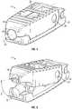
- FIG. 1is a perspective view of an implant in a collapsed position according to one embodiment.
- FIG. 2is a perspective view of the implant of FIG. 1 in an expanded position according to one embodiment.
- FIG. 3is a side view of the implant of FIG. 1 in the collapsed position according to one embodiment.
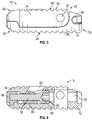
- FIG. 4is a cross-section view of the implant of FIG. 1 in a collapsed position according to one embodiment.
- FIG. 5is a side view of the implant of FIG. 1 in an expanded position according to one embodiment.
- FIG. 6is a side view of the implant of FIG. 1 in an expanded position according to one embodiment.
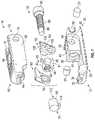
- FIG. 7is an exploded view of the implant of FIG. 1 according to one embodiment.
- FIG. 8is another exploded view of the implant of FIG. 1 according to one embodiment.
- FIG. 9is a side cross-section view of an upper support of the implant of FIG. 1 according to one embodiment.
- FIG. 10is a top view of the implant of FIG. 1 according to one embodiment.
- FIG. 11is a bottom view of the implant of FIG. 1 according to one embodiment.
- FIG. 12is a front view of the implant of FIG. 1 according to one embodiment.
- FIG. 13is a rear view of the implant of FIG. 1 according to one embodiment.
- the expandable implantmay be usable in connection with the spine (e.g., between vertebral bodies) or other parts of the human body.
- the implantprovides a lumbar interbody expandable implant that expands in a lordotic fashion.
- the implantmay include an upper support hingedly or pivotally coupled to a lower support, such that an amount of lordosis provided by the implant can be adjusted as desired.
- a control assemblymay include a control shaft and a control member mounted to the control shaft. One or more pivoting members are pivotally coupled to the control member and move within one or more control channels in the upper implant.
- rotation of the control shaftcauses translation of the control member along the control shaft relative to the lower support.
- ramp surfaces on the pivoting member(s)slidingly engage corresponding ramp surface(s) on the upper support to cause expansion or contraction of the implant (e.g., to move the implant between a collapsed position and an expanded position, and intermediate positions therebetween).
- the implants disclosed hereinmay be made of any suitable materials, including a variety of metals, plastics, composites, or other suitable bio-compatible materials. In some embodiments, some or all of the components of the implants disclosed herein may be made of the same material, while in other embodiments, different materials may be used for different components.
- Implant 10is usable, for example, between and/or within portions of bone (e.g., between and/or within vertebral bodies or the spine or other portions of bone).
- implant 10includes a lower support 12 (e.g., a base support or assembly, a foundational plate, endplate, or member, etc.) and an upper support 14 (e.g., an adjustable support or assembly, a hinged plate, endplate, or member, etc.) adjustably coupled to the lower support 12 by way of a control assembly 16 (e.g., an adjustment assembly, etc.) and one or more pivot pins 20 .
- a lower support 12e.g., a base support or assembly, a foundational plate, endplate, or member, etc.
- an upper support 14e.g., an adjustable support or assembly, a hinged plate, endplate, or member, etc.
- a control assembly 16e.g., an adjustment assembly, etc.
- upper support 14pivots relative to lower support 12 as a result of user manipulation of control assembly 16 (e.g., as a result of rotation or movement of a control shaft or member, etc.).
- upper support 14expands relative to lower support 12 in a lordotic fashion to mimic the natural curvature of the human spine. The amount of lordosis can be increased or decreased by manipulation of control assembly 16 .
- An end cap 18e.g., a distal end member, etc.
- Pivot pins 20extend at least partially through lower support 12 and upper support 14 to enable relative pivoting adjustment between upper support 14 and lower support 12 .
- Implant 10is movable between a collapsed position, as shown, for example, in FIGS. 1 , 3 , and 4 , and an expanded position, as shown, for example, in FIGS. 2 , 5 , and 6 . Further, implant 10 may be adjusted to any intermediate position between a fully collapsed position and a fully expanded position. Further yet, the amount of total expansion, (e.g., the maximum expansion angle 21 relative to axis 22 shown in FIGS. 1 and 2 ) may be varied to suit a particular application.
- lower support 12extends between a distal end 28 and a proximal end 30 and includes a bottom surface 24 having a plurality of ridges 26 (e.g., teeth, etc.) formed by corresponding grooves or channels. Ridges 26 are configured to facilitate gripping of adjacent portions of bone.
- a lower distal recess 32is provided at distal end 28 , and a retention groove 34 extends from lower distal recess 32 . Retention groove 34 is configured to receive a retention projection 114 of end cap 18 , as discussed in greater detail elsewhere herein.
- lower support 12includes an inner housing 36 .
- Inner housing 36is defined by a front wall 38 and side walls 40 that extend from front wall 38 toward proximal end 30 of lower support 12 .
- Inner housing 36in some embodiments defines a central aperture 48 (e.g., a cavity, etc.) providing access to an interior of implant 10 .
- Central aperture 48may be configured to receive bone growth material and/or bone material from adjacent portions of bone.
- Lower support 12further includes an access bore 50 , tool recesses 52 , and an inclined surface 54 .
- Access bore 50provides access to central aperture 48 (e.g., for delivery of bone growth or other material) and control assembly 16 (e.g., to enable manipulation of control assembly 16 and control of the expansion and/or contraction of implant 10 ).
- Tool recesses 52are configured to receive one or more tool portions to enable positioning of implant 10 in a desired position (e.g., within an intervertebral space, etc.).
- Inclined surface 54see FIG.
- inclined surface 54is aligned with (e.g., substantially coplanar with) a top surface 56 of upper support 14 to provide additional support to adjacent portions of bone.
- inclined surface 54is angled downward in a proximal direction relative to a top surface 56 of upper support 14 when implant 10 is in a collapsed position.
- the angular position of inclined surface 54is in some embodiments intended to accommodate the natural curvature of the human spine.
- upper support 14extends between a distal end 60 and a proximal end 62 and includes a top surface 56 having a plurality of ridges 58 (e.g., teeth, etc.) formed by corresponding grooves or channels. Ridges 58 are configured to facilitate gripping of adjacent portions of bone.
- An upper distal recess 64is provided at distal end 60 and receives end cap 18 . Sidewalls 68 extend downward relative to top surface 56 .
- upper support 14includes two opposing sidewalls 68 .
- Each sidewall 68includes a pivot pin aperture 70 configured to receive a pivot pin 20 there through to enable pivoting movement of upper support 14 relative to lower support 12 .
- Upper support 14also includes a rear aperture or cavity 72 that receives all or a portion of inner housing 36 when implant 10 is a collapsed position.
- a control aperture 66extends through upper support 14 and is defined at least partially by distal ramp surfaces 74 and proximal ramp surfaces 76 .
- An alignment channel 77extends along each sidewall 68 and along control aperture 66 .
- control aperture 66receives portions of control assembly 16 , and the angle of control aperture 66 relative to axis 22 may be designed to provide a desired rate of pivoting of upper support 14 relative to lower support 12 .
- control assembly 16includes a control shaft 78 , a control member 80 , and one or more pivot members 82 .
- control assembly 16includes a pair of pivot members 82 , 83 positioned on opposite sides of control member 80 .
- Control shaft 78is rotatable or otherwise manipulatable to cause translation or movement of control member 80 along control shaft 78 .
- pivot members 82move within control aperture 66 (see FIG. 6 ) to change the angular position of upper support 144 relative to lower support 12 .
- Control shaft 78includes a head 84 , a threaded portion 86 , an end portion 88 and a receiver 90 provided in head 84 .
- Head 84defines a first end of control shaft 78 and end portion 88 defines a second opposite end of control shaft 78 , with threaded portion 86 provided there between.
- Head 84is received in a control member bore 44 and engages a shoulder 46 to limit proximal movement of control shaft 78 during use of implant 10 .
- End portion 88is received by end cap 18 to limit distal movement of control shaft 78 .
- Control member 80is received on control shaft 78 .
- control member 80includes a base member 81 and one or more pivot members 82 .
- control member 80includes first and second pivot members 82 , 83 pivotally coupled to opposite sides of base member 81 .
- Base member 81includes a central portion 92 having a threaded bore 94 that threadingly engages threaded portion 86 of control shaft 78 .
- Base member 81further includes a bottom 96 and a pair cylindrical pivot bosses 98 . Due to the threaded engagement of base member 81 onto control shaft 78 , rotation of control shaft 78 causes movement (e.g., translational movement) of base member 81 along control shaft 78 .
- each pivot member 82 , 83includes a pivot aperture 100 that receives one of the pivot bosses 98 to enable pivoting movement of pivot members 82 , 83 relative to base member 81 about pivot bosses 98 .
- Pivot member 82 , 83are mirror images of each other in one embodiment, and as such, pivot member 82 will be described in detail, with the understanding that pivot member 83 shares similar features.
- pivot member 83may include an alignment guide 107 that is similar to alignment guide 106 .
- Pivot member 82includes distal ramp surface 102 , proximal ramp surface 104 , alignment guide 106 , and top surface 108 .
- Distal ramp surface 102 of pivot member 82slidingly engages distal ramp surface 74 of upper support 14 .
- proximal ramp surface 104 of pivot member 82slidingly engages proximal ramp surface 76 of upper support 14 .
- pivot members 82 , 83pivot about pivot bosses 98 as the corresponding distal and proximal ramp surfaces of the pivot members 82 , 83 and upper support 14 engage, causing upper support 14 to move relative to lower support 12 , and implant 10 to move toward an expanded or collapsed position, depending on the direction of rotation of control shaft 78 .
- Alignment guide 106 of pivot member 82is received within alignment channel 77 of upper support 14 to maintain proper alignment between components and facilitate movement of upper support 14 relative to lower support 12 .
- top surface 108 of pivot member 82when implant 10 is in a collapsed position, is generally aligned with top surface 56 of upper support 14 .
- top surface 108may be substantially smooth, while in other embodiments, top surface 108 may be textured, include teeth or groves, or have other surface features.
- End cap 18includes a main body 110 , a control shaft bore 112 , and a retention projection 114 .
- Control shaft bore 112receives end portion 88 of control shaft 78 .
- Retention projection 114is received in retention groove 34 in lower support 12 to retain end cap 18 in place. In one embodiment, end cap 18 is rotated approximately 90 degrees to properly seat retention projection 114 within retention groove 34 .
- a userpositions implant 10 into a desired position, such as an intervertebral space, while collapsed, as shown, for example, in FIG. 1 .
- a desired positionsuch as an intervertebral space
- an appropriate toolmay engage tool recesses 52 on lower support 12 .
- implant 10is inserted into a space distal end first, with the appropriate tool engaging the proximal end of implant 10 .
- implant 10may then be expanded to provide, for example, a desired amount of lordosis.
- Implant 10may be expanded to a fully expanded position, or any intermediate expanded position between the fully collapsed position and the fully expanded position.
- a userinserts an appropriate expansion tool through access bore 50 in lower support 12 and into receiver 90 in head 84 of control shaft 78 .
- the expansion toolmay then be used to manipulate the control shaft 78 to cause expansion of the implant 10 .
- receiver 90may be hexagonal shaped, and the tool may be a hexagonal driver. Other suitable receivers and tools may be used according to various alternative embodiments.
- control member 80translates along control shaft 78 .
- control member 80moves toward the distal end of lower support 12 as shown in FIGS. 4 and 6 .
- Bottom 96 of control member 80rides along a surface of lower support 12 , and the travel of control member 80 is limited by limit shoulder 53 , as shown in FIG. 6 .
- shoulder 53is integrally formed (e.g., molded, etc.) with a remaining portion of lower support 12 to provide sufficient support for control shaft 78 during expansion of implant 10 .
- pivot members 82 , 83engage ramp surfaces of upper support 14 and cause upper support 14 to rotate about pivot pins 20 .
- pivot members 82pivot about pivot bosses 98 on base member 81 to maintain proper alignment between the ramp surfaces on pivot members 82 , 83 and the ramp surfaces on upper support 14 .
- the pivoting features of upper support 14 and pivot members 82 , 83maintain a generally parallel relationship between ramp surfaces 74 , 76 of upper support 14 and ramp surfaces 102 , 104 of pivot members 82 , 83 , which may facilitate the wedging action required to move upper support 14 relative to lower support 12 .
- control shaft 78is rotated in an opposite direction from that used during expansion of implant 10 .
- control member 80moves toward the proximal end of lower support as shown in FIGS. 4 and 6 .
- ramp surfaces on pivot membersengage ramp surfaces of upper support 14 and cause upper support 14 to rotate about pivot pins 20 .
- the upper support 14includes a control aperture 66 configured to receive the pivot member 83 .
- the alignment guide 107 of the pivot member 83may slide within the alignment channel 77 of the control aperture 66 as the implant 10 expands.
- the distal ramp surface 74 and the proximal ramp surface 76may interface with the ramp surfaces of the pivot member 83 when the implant 10 expands.
- the angle of expansion (e.g., angle 21 ) and the rate of angular expansionmay be customized by altering the angles of the ramp surfaces 74 , 76 and the alignment channel 77 .
- the upper support 14may also include a second control aperture 77 opposite the control aperture 66 configured to receive the pivot member 82 in a similar manner (see FIG. 10 ).
- the upper support 14is also shown include a pivot pin aperture 70 configured to receive a pivot pin 20 there through to enable pivoting movement of upper support 14 relative to lower support 12 .
- pivot member 83includes an alignment guide 107 that is received by the first alignment channel 77 in the upper support 14 .
- pivot member 82includes an alignment guide 106 that is received by the second alignment channel 77 in the upper support.
- the rear aperture 72 of the upper support 14also receives all or a portion of the inner housing 36 .
- the inner housing 36further defines the central aperture 48 (e.g., a cavity, etc.) providing access to an interior of implant 10 from the top surface 56 of the upper support and from the bottom surface 24 of the lower support 12 .
- Central aperture 48may be configured to receive bone growth material and/or bone material from adjacent portions of bone.
- FIGS. 12 and 13a front and rear view, respectively, of the implant 10 are shown.
- the upper support 14 and the lower support 12form a bull shaped nose that receives the end cap 18 at the front of the implant 10 .
- the bull shaped noseallows the implant 10 to be inserted into a desired location before the implant 10 is expanded.
- the control shaft 78is received by the rear of the implant 10 .
- the head 84is positioned away from the rear end of the implant 10 , and is at least partially received by the control member bore 44 in the lower support 12 .
- Coupledmeans the joining of two members directly or indirectly to one another. Such joining may be stationary (e.g., permanent or fixed) or moveable (e.g., removable or releasable). Such joining may be achieved with the two members coupled directly to each other, with the two members coupled to each other using a separate intervening member and any additional intermediate members coupled with one another, or with the two members coupled to each other using an intervening member that is integrally formed as a single unitary body with one of the two members.
- Coupledor variations thereof are modified by an additional term (e.g., directly coupled)
- the generic definition of “coupled” provided aboveis modified by the plain language meaning of the additional term (e.g., “directly coupled” means the joining of two members without any separate intervening member), resulting in a narrower definition than the generic definition of “coupled” provided above.
- Such couplingmay be mechanical, electrical, or fluidic.
Landscapes
- Health & Medical Sciences (AREA)
- Engineering & Computer Science (AREA)
- Biomedical Technology (AREA)
- Orthopedic Medicine & Surgery (AREA)
- Neurology (AREA)
- Vascular Medicine (AREA)
- Transplantation (AREA)
- Heart & Thoracic Surgery (AREA)
- Oral & Maxillofacial Surgery (AREA)
- Life Sciences & Earth Sciences (AREA)
- Animal Behavior & Ethology (AREA)
- General Health & Medical Sciences (AREA)
- Public Health (AREA)
- Veterinary Medicine (AREA)
- Cardiology (AREA)
- Prostheses (AREA)
Abstract
Description
Claims (19)
Priority Applications (5)
| Application Number | Priority Date | Filing Date | Title |
|---|---|---|---|
| US17/014,546US11554020B2 (en) | 2020-09-08 | 2020-09-08 | Expandable implant with pivoting control assembly |
| CN202180064474.0ACN116322575A (en) | 2020-09-08 | 2021-09-07 | Expandable implant with pivot control assembly |
| EP21787114.4AEP4210637A1 (en) | 2020-09-08 | 2021-09-07 | Expandable implant with pivoting control assembly |
| PCT/US2021/049280WO2022055878A1 (en) | 2020-09-08 | 2021-09-07 | Expandable implant with pivoting control assembly |
| US17/990,101US12364610B2 (en) | 2020-09-08 | 2022-11-18 | Expandable implant with pivoting control assembly |
Applications Claiming Priority (1)
| Application Number | Priority Date | Filing Date | Title |
|---|---|---|---|
| US17/014,546US11554020B2 (en) | 2020-09-08 | 2020-09-08 | Expandable implant with pivoting control assembly |
Related Child Applications (1)
| Application Number | Title | Priority Date | Filing Date |
|---|---|---|---|
| US17/990,101ContinuationUS12364610B2 (en) | 2020-09-08 | 2022-11-18 | Expandable implant with pivoting control assembly |
Publications (2)
| Publication Number | Publication Date |
|---|---|
| US20220071772A1 US20220071772A1 (en) | 2022-03-10 |
| US11554020B2true US11554020B2 (en) | 2023-01-17 |
Family
ID=78080448
Family Applications (2)
| Application Number | Title | Priority Date | Filing Date |
|---|---|---|---|
| US17/014,546ActiveUS11554020B2 (en) | 2020-09-08 | 2020-09-08 | Expandable implant with pivoting control assembly |
| US17/990,101Active2040-10-20US12364610B2 (en) | 2020-09-08 | 2022-11-18 | Expandable implant with pivoting control assembly |
Family Applications After (1)
| Application Number | Title | Priority Date | Filing Date |
|---|---|---|---|
| US17/990,101Active2040-10-20US12364610B2 (en) | 2020-09-08 | 2022-11-18 | Expandable implant with pivoting control assembly |
Country Status (4)
| Country | Link |
|---|---|
| US (2) | US11554020B2 (en) |
| EP (1) | EP4210637A1 (en) |
| CN (1) | CN116322575A (en) |
| WO (1) | WO2022055878A1 (en) |
Citations (248)
| Publication number | Priority date | Publication date | Assignee | Title |
|---|---|---|---|---|
| US904434A (en) | 1907-03-23 | 1908-11-17 | Packard Motor Car Co | Oil-pump. |
| DE9407806U1 (en) | 1994-05-11 | 1994-07-14 | Aesculap AG & Co. KG, 78532 Tuttlingen | Intervertebral implant |
| FR2717068A1 (en) | 1994-03-14 | 1995-09-15 | Biomat | Intersomatic cage insertable between two vertebral bodies |
| WO1995031158A1 (en) | 1994-05-11 | 1995-11-23 | Jean Taylor | Vertebral implant |
| US5522899A (en) | 1988-06-28 | 1996-06-04 | Sofamor Danek Properties, Inc. | Artificial spinal fusion implants |
| US5609635A (en) | 1988-06-28 | 1997-03-11 | Michelson; Gary K. | Lordotic interbody spinal fusion implants |
| US5658335A (en) | 1995-03-09 | 1997-08-19 | Cohort Medical Products Group, Inc. | Spinal fixator |
| US5658337A (en) | 1994-05-23 | 1997-08-19 | Spine-Tech, Inc. | Intervertebral fusion implant |
| EP0880950A1 (en) | 1997-05-30 | 1998-12-02 | Biomat | Intervertebral cervical cage |
| WO1999026562A1 (en) | 1997-11-25 | 1999-06-03 | Jean Taylor | Vertebral implant adapted to be inserted from the rear in an intervertebral space |
| US6045579A (en) | 1997-05-01 | 2000-04-04 | Spinal Concepts, Inc. | Adjustable height fusion device |
| US6113638A (en) | 1999-02-26 | 2000-09-05 | Williams; Lytton A. | Method and apparatus for intervertebral implant anchorage |
| US6129763A (en) | 1996-09-13 | 2000-10-10 | Chauvin; Jean-Luc | Expandable osteosynthesis cage |
| US6176882B1 (en) | 1998-02-20 | 2001-01-23 | Biedermann Motech Gmbh | Intervertebral implant |
| US6375682B1 (en) | 2001-08-06 | 2002-04-23 | Lewis W. Fleischmann | Collapsible, rotatable and expandable spinal hydraulic prosthetic device |
| US6443990B1 (en) | 1997-08-06 | 2002-09-03 | Synthes (U.S.A.) | Adjustable intervertebral implant |
| US6443989B1 (en) | 2000-12-04 | 2002-09-03 | Roger P. Jackson | Posterior expandable fusion cage |
| US20020128716A1 (en) | 1999-07-26 | 2002-09-12 | Howard Cohen | Spinal surgical prosthesis |
| KR200290058Y1 (en) | 2002-05-11 | 2002-09-26 | 정연문 | Lumbar vertebra fixture |
| US20020143399A1 (en) | 2001-04-02 | 2002-10-03 | Ulrich Gmbh & Co. Kg | Anchorable vertebral implant |
| US20020147461A1 (en) | 2001-04-06 | 2002-10-10 | Aldrich William N. | Apparatus and methods for closing openings in spinal discs |
| US20020177897A1 (en) | 2001-02-04 | 2002-11-28 | Michelson Gary K. | Instrumentation and method for inserting and deploying and expandable interbody spinal fusion implant |
| US6491724B1 (en) | 1999-08-13 | 2002-12-10 | Bret Ferree | Spinal fusion cage with lordosis correction |
| US6641614B1 (en) | 1997-05-01 | 2003-11-04 | Spinal Concepts, Inc. | Multi-variable-height fusion device |
| US6648917B2 (en) | 2001-10-17 | 2003-11-18 | Medicinelodge, Inc. | Adjustable bone fusion implant and method |
| US20030236520A1 (en) | 2002-06-25 | 2003-12-25 | Roy Lim | Minimally invasive expanding spacer and method |
| US6685742B1 (en) | 2002-11-12 | 2004-02-03 | Roger P. Jackson | Articulated anterior expandable spinal fusion cage system |
| US6723126B1 (en)* | 2002-11-01 | 2004-04-20 | Sdgi Holdings, Inc. | Laterally expandable cage |
| WO2004052245A1 (en) | 2002-12-06 | 2004-06-24 | Synthes Ag Chur | Intervertebral implant |
| US6773460B2 (en) | 2000-12-05 | 2004-08-10 | Roger P. Jackson | Anterior variable expandable fusion cage |
| US20040230309A1 (en) | 2003-02-14 | 2004-11-18 | Depuy Spine, Inc. | In-situ formed intervertebral fusion device and method |
| US6849093B2 (en) | 2001-03-09 | 2005-02-01 | Gary K. Michelson | Expansion constraining member adapted for use with an expandable interbody spinal fusion implant and method for use thereof |
| US20050131536A1 (en) | 2003-12-11 | 2005-06-16 | Lukas Eisermann | Expandable intervertebral implant |
| US20050177235A1 (en) | 2004-02-10 | 2005-08-11 | Baynham Bret O. | Spinal fusion device |
| US20050222681A1 (en) | 2002-06-17 | 2005-10-06 | Richard Richley | Devices and methods for minimally invasive treatment of degenerated spinal discs |
| US20050278036A1 (en) | 2004-06-09 | 2005-12-15 | Ceravic | Method for restoration of human or animal bone anatomy, and expansible prosthetic implant allowing implementation of this method |
| US20060030943A1 (en) | 2004-07-23 | 2006-02-09 | Marc Peterman | Expandable spinal implant having interlocking geometry for structural support |
| US20060089715A1 (en) | 2004-06-07 | 2006-04-27 | Csaba Truckai | Implants and methods for treating bone |
| US20060122701A1 (en) | 2004-11-23 | 2006-06-08 | Kiester P D | Posterior lumbar interbody fusion expandable cage with lordosis and method of deploying the same |
| WO2006102485A2 (en) | 2005-03-22 | 2006-09-28 | St. Francis Medical Technologies, Inc. | Interspinous process implant with slide-in distraction piece and method of implantation |
| WO2006105437A2 (en) | 2005-03-31 | 2006-10-05 | Life Spine, Inc. | Expandable spinal interbody and intravertebral body devices |
| US20060241621A1 (en) | 2005-04-12 | 2006-10-26 | Moskowitz Mosheh T | Bi-directional fixating transvertebral body screws, zero-profile horizontal intervertebral miniplates, expansile intervertebral body fusion devices, and posterior motion-calibrating interarticulating joint stapling device for spinal fusion |
| US20060253201A1 (en) | 2004-11-03 | 2006-11-09 | Mcluen Design, Inc. | Bone fusion device |
| US20070072475A1 (en) | 2005-09-26 | 2007-03-29 | Justin Daniel F | Universal spinal disc implant system |
| US7214243B2 (en) | 2002-10-21 | 2007-05-08 | 3Hbfm, Llc | Intervertebral disk prosthesis |
| US7217291B2 (en) | 2003-12-08 | 2007-05-15 | St. Francis Medical Technologies, Inc. | System and method for replacing degenerated spinal disks |
| US7220280B2 (en) | 2002-10-16 | 2007-05-22 | Advanced Medical Technologies Ag | Spreader implant for placement between vertebrae |
| US20070213739A1 (en) | 2001-03-01 | 2007-09-13 | Sdgi Holdings, Inc. | Method for using dynamic lordotic guard with movable extensions for creating an implantation space posteriorly in the lumbar spine |
| US20070244485A1 (en) | 2004-09-21 | 2007-10-18 | Greenhalgh E S | Expandable support device and method of use |
| US20070270968A1 (en) | 2004-02-10 | 2007-11-22 | Baynham Bret O | Plif opposing wedge ramp |
| US20080119853A1 (en) | 2006-11-21 | 2008-05-22 | Jeffrey Felt | Methods and apparatus for minimally invasive modular interbody fusion devices |
| US20080119945A1 (en) | 2005-03-24 | 2008-05-22 | Synthes (U.S.A.) | Device for the Cement Augmentation of Bone Implants |
| US20080140207A1 (en) | 2006-12-07 | 2008-06-12 | Interventional Spine, Inc. | Intervertebral implant |
| US20080147193A1 (en) | 2006-11-23 | 2008-06-19 | Wilfried Matthis | Expandable intervertebral implant |
| US20080243251A1 (en) | 2007-03-30 | 2008-10-02 | Shawn Stad | Intervertebral Device Having Expandable Endplates |
| US7473276B2 (en) | 2002-12-17 | 2009-01-06 | Synthes (U.S.A.) | Intervertebral implant with joint parts mounted on roller bodies |
| US20090062833A1 (en) | 2007-08-27 | 2009-03-05 | Vermillion Technologies, Llc | Device and method for placement of interbody device |
| KR100905962B1 (en) | 2008-03-17 | 2009-07-06 | 조철민 | Intervertebral expansion cage device and mounting method |
| US20090198338A1 (en) | 2008-02-04 | 2009-08-06 | Phan Christopher U | Medical implants and methods |
| US20090198339A1 (en) | 2008-02-06 | 2009-08-06 | Nuvasive, Inc. | Systems and methods for spinal fusion |
| WO2009124269A1 (en) | 2008-04-05 | 2009-10-08 | Synthes Usa, Llc | Expandable intervertebral implant |
| US20100082109A1 (en) | 2008-09-22 | 2010-04-01 | Stout Medical Group, L.P. | Expandable intervertebral implant |
| US7722674B1 (en) | 2005-08-12 | 2010-05-25 | Innvotec Surgical Inc. | Linearly expanding spine cage for enhanced spinal fusion |
| US20100191336A1 (en) | 2008-11-12 | 2010-07-29 | Stout Medical Group. L.P. | Fixation device and method |
| US20100204795A1 (en) | 2008-11-12 | 2010-08-12 | Stout Medical Group, L.P. | Fixation device and method |
| US20100211176A1 (en) | 2008-11-12 | 2010-08-19 | Stout Medical Group, L.P. | Fixation device and method |
| US20100234889A1 (en) | 2009-03-13 | 2010-09-16 | Harold Hess | Interspinous Process Implant and Fusion Cage Spacer |
| US20100249937A1 (en) | 2009-03-27 | 2010-09-30 | Spinal Elements, Inc. | Flanged interbody fusion device |
| USD626233S1 (en) | 2008-02-28 | 2010-10-26 | Stryker Spine | Expandable intervertebral implant |
| US7828849B2 (en) | 2003-02-03 | 2010-11-09 | Warsaw Orthopedic, Inc. | Expanding interbody implant and articulating inserter and method |
| US20100286777A1 (en) | 2009-05-08 | 2010-11-11 | Stryker Spine | Stand alone anterior cage |
| US7846188B2 (en) | 2005-04-12 | 2010-12-07 | Moskowitz Nathan C | Bi-directional fixating transvertebral body screws, zero-profile horizontal intervertebral miniplates, total intervertebral body fusion devices, and posterior motion-calibrating interarticulating joint stapling device for spinal fusion |
| US7854766B2 (en) | 2004-05-13 | 2010-12-21 | Moskowitz Nathan C | Artificial total lumbar disc for unilateral safe and simple posterior placement in the lumbar spine, and removable bifunctional screw which drives vertical sliding expansile plate expansion, and interplate widening, and angled traction spikes |
| WO2010148112A1 (en) | 2009-06-16 | 2010-12-23 | Stout Medical Group, L.P. | Expandable support device and method of use |
| US7879098B1 (en) | 2005-10-19 | 2011-02-01 | Simmons Jr James W | Expandable lordosis stabilizing cage |
| US20110046682A1 (en) | 2009-07-06 | 2011-02-24 | Synthes Gmbh Or Synthes Usa, Llc | Expandable fixation assemblies |
| US20110054538A1 (en) | 2008-03-14 | 2011-03-03 | Eli Zehavi | Segmented insert for intervertebral support |
| US20110077738A1 (en) | 2009-09-28 | 2011-03-31 | Lfc Sp. Z.O.O. | Device for surgical displacement of vertebrae |
| US7942903B2 (en) | 2005-04-12 | 2011-05-17 | Moskowitz Ahmnon D | Bi-directional fixating transvertebral body screws and posterior cervical and lumbar interarticulating joint calibrated stapling devices for spinal fusion |
| US20110144755A1 (en) | 2004-02-10 | 2011-06-16 | Baynham Bret O | PLIF opposing wedge ramp |
| US20110144753A1 (en) | 2009-12-10 | 2011-06-16 | Connie Marchek | Bellows-Like Expandable Interbody Fusion Cage |
| US7972363B2 (en) | 2005-04-12 | 2011-07-05 | Moskowitz Ahmnon D | Bi-directional fixating/locking transvertebral body screw/intervertebral cage stand-alone constructs and posterior cervical and lumbar interarticulating joint stapling guns and devices for spinal fusion |
| US20110172774A1 (en) | 2010-01-11 | 2011-07-14 | Armando Varela | Expandable intervertebral implant and associated surgical method |
| US20110172716A1 (en) | 2010-01-12 | 2011-07-14 | Chad Glerum | Expandable Spacer and Method For Use Thereof |
| US20110178599A1 (en) | 2009-09-17 | 2011-07-21 | Brett Darrell C | Intervertebral implant having extendable bone fixation members |
| US20110190817A1 (en) | 2009-11-06 | 2011-08-04 | Synthes Usa, Llc | Minimally invasive interspinous process spacer implants and methods |
| US20110282453A1 (en) | 2010-05-13 | 2011-11-17 | Stout Medical Group, L.P. | Fixation device and method |
| US8062375B2 (en) | 2009-10-15 | 2011-11-22 | Globus Medical, Inc. | Expandable fusion device and method of installation thereof |
| US8070817B2 (en) | 2006-06-28 | 2011-12-06 | M.O.R.E. Medical Solutions Gmbh | Vertebral implant |
| US20110301711A1 (en) | 2010-06-02 | 2011-12-08 | Warsaw Orthopedic, Inc. | System and methods for a laterally expanding implant |
| US20110319997A1 (en) | 2010-06-25 | 2011-12-29 | Chad Glerum | Expandable Fusion Device and Method of Installation Thereof |
| US20120022652A1 (en) | 2010-06-18 | 2012-01-26 | Roger Berger | Spine disc replacement with compliant articulating core |
| US20120029636A1 (en)* | 2010-08-02 | 2012-02-02 | Ragab Ashraf A | Bone Cage with Components for Controlled Expansion |
| US20120046748A1 (en) | 2010-02-24 | 2012-02-23 | Mark Weiman | Expandable Intervertebral Spacer and Method of Posterior Insertion Thereof |
| US20120059472A1 (en) | 2010-09-03 | 2012-03-08 | Mark Weiman | Expandable Fusion Device and Method of Installation Thereof |
| US20120059474A1 (en) | 2010-09-03 | 2012-03-08 | Mark Weiman | Expandable Fusion Device and Method of Installation Thereof |
| US20120071978A1 (en) | 2010-06-29 | 2012-03-22 | Jann-Paul Suedkamp | Distractible intervertebral implant |
| CN102427769A (en) | 2009-03-12 | 2012-04-25 | 维克辛姆公司 | Apparatus for bone restoration of the spine and methods of use |
| US20120185049A1 (en) | 2010-01-11 | 2012-07-19 | Innova Spinal Technologies, Llc | Expandable intervertebral implant and associated surgical method |
| US8257370B2 (en) | 2005-04-12 | 2012-09-04 | Moskowitz Ahmnon D | Posterior cervical and lumbar interarticulating joint staples, stapling guns, and devices for spinal fusion |
| US8303663B2 (en) | 2009-07-22 | 2012-11-06 | Spinex Tec, Llc | Methods and apparatuses for vertebral body distraction and fusion employing a coaxial screw gear sleeve mechanism |
| US20120330422A1 (en) | 2010-09-03 | 2012-12-27 | Mark Weiman | Expandable Fusion Device and Method of Installation Thereof |
| US8382842B2 (en) | 2009-05-14 | 2013-02-26 | Stout Medical Group, L.P. | Expandable support device and method of use |
| US8388686B2 (en) | 2002-12-17 | 2013-03-05 | Max Aebi | Intervertebral implant with tiltable joint parts |
| US8398713B2 (en) | 2010-09-03 | 2013-03-19 | Globus Medical, Inc. | Expandable fusion device and method of installation thereof |
| US20130085572A1 (en) | 2011-09-30 | 2013-04-04 | Chad Glerum | Expandable Fusion Device and Method of Installation Thereof |
| US20130103156A1 (en) | 2011-10-19 | 2013-04-25 | Evan PACKER | Laterally expandable spinal prosthesis |
| US20130144391A1 (en) | 2010-07-15 | 2013-06-06 | Nlt Spine Ltd | Surgical systems and methods for implanting deflectable implants |
| US20130158669A1 (en) | 2012-02-13 | 2013-06-20 | Arno Sungarian | Expandable Self-Anchoring Interbody Cage for Orthopedic Applications |
| US20130158664A1 (en)* | 2011-12-19 | 2013-06-20 | Warsaw Orthopedic, Inc. | Expandable interbody implant and methods of use |
| US20130158668A1 (en) | 2011-12-14 | 2013-06-20 | Biospine, Llc | Unilateral moveable interbody fusion device and method of use |
| US20130211526A1 (en) | 2011-08-16 | 2013-08-15 | Stryker Spine | Expandable implant |
| US8518120B2 (en) | 2009-10-15 | 2013-08-27 | Globus Medical, Inc. | Expandable fusion device and method of installation thereof |
| US8551173B2 (en) | 2008-01-17 | 2013-10-08 | DePuy Synthes Products, LLC | Expandable intervertebral implant and associated method of manufacturing the same |
| US8556979B2 (en) | 2009-10-15 | 2013-10-15 | Globus Medical, Inc. | Expandable fusion device and method of installation thereof |
| US8597360B2 (en) | 2004-11-03 | 2013-12-03 | Neuropro Technologies, Inc. | Bone fusion device |
| US8628578B2 (en) | 2011-12-19 | 2014-01-14 | Warsaw Orthopedic, Inc. | Expandable interbody implant and methods of use |
| US8632595B2 (en) | 2010-09-03 | 2014-01-21 | Globus Medical, Inc. | Expandable fusion device and method of installation thereof |
| US8663332B1 (en) | 2012-12-13 | 2014-03-04 | Ouroboros Medical, Inc. | Bone graft distribution system |
| US8709086B2 (en) | 2009-10-15 | 2014-04-29 | Globus Medical, Inc. | Expandable fusion device and method of installation thereof |
| US20140148904A1 (en) | 2012-08-08 | 2014-05-29 | James C. Robinson | Expandable intervertebral cage assemblies and methods |
| US20140236296A1 (en) | 2013-02-20 | 2014-08-21 | Erik Wagner | Expandable fusion device for positioning between adjacent vertebral bodies |
| US20140249629A1 (en) | 2005-04-12 | 2014-09-04 | Ahmnon D. Moskowitz | Zero-profile expandable intervertebral spacer devices for distraction and spinal fusion and a universal tool for their placement and expansion |
| WO2014134590A1 (en) | 2013-03-01 | 2014-09-04 | Globus Medical, Inc. | Articulating expandable intervertebral implant |
| EP2777633A2 (en) | 2013-03-15 | 2014-09-17 | Expanding Orthopedics, Inc. | Expandable orthopedic devices |
| US20140277500A1 (en)* | 2013-03-15 | 2014-09-18 | Neuropro Technologies, INC | Bodiless bone fusion device, apparatus and method |
| US20140277473A1 (en) | 2013-03-15 | 2014-09-18 | Pioneer Surgical Technology, Inc. | Systems and methods for inserting an expandable intervertebral device |
| US20140288653A1 (en) | 2013-03-20 | 2014-09-25 | Kuei Jung CHEN | Textured implant device having series extendible blades |
| US8845734B2 (en) | 2010-09-03 | 2014-09-30 | Globus Medical, Inc. | Expandable fusion device and method of installation thereof |
| US8845731B2 (en) | 2010-09-03 | 2014-09-30 | Globus Medical, Inc. | Expandable fusion device and method of installation thereof |
| US8852279B2 (en) | 2010-09-03 | 2014-10-07 | Globus Medical, Inc. | Expandable fusion device and method of installation thereof |
| WO2014165319A1 (en) | 2013-04-03 | 2014-10-09 | Globus Medical, Inc. | Expandable fusion device and method of installation thereof |
| US20140343678A1 (en) | 2013-05-20 | 2014-11-20 | K2M, Inc. | Adjustable Implant and Insertion Tool |
| US8894712B2 (en) | 2010-01-11 | 2014-11-25 | Innova Spinal Technologies, Llc | Expandable intervertebral implant and associated surgical method |
| US8940052B2 (en) | 2012-07-26 | 2015-01-27 | DePuy Synthes Products, LLC | Expandable implant |
| US20150066145A1 (en) | 2013-08-29 | 2015-03-05 | Andrew Rogers | Expandable and adjustable lordosis interbody fusion system |
| US20150100128A1 (en) | 2009-10-15 | 2015-04-09 | Globus Medical, Inc. | Expandable Fusion Device and Method of Installation Thereof |
| US20150112438A1 (en) | 2013-10-18 | 2015-04-23 | Spine Wave, Inc. | Method of expanding an intradiscal space and providing an osteoconductive path during expansion |
| WO2015063721A1 (en) | 2013-10-31 | 2015-05-07 | Nlt Spine Ltd. | Adjustable implant |
| US9034041B2 (en) | 2005-03-31 | 2015-05-19 | Life Spine, Inc. | Expandable spinal interbody and intravertebral body devices |
| US9034045B2 (en) | 2013-03-15 | 2015-05-19 | Globus Medical, Inc | Expandable intervertebral implant |
| WO2015085111A1 (en) | 2013-12-05 | 2015-06-11 | Spinal Elements, Inc | Expandable interbody device |
| US9060876B1 (en) | 2015-01-20 | 2015-06-23 | Ouroboros Medical, Inc. | Stabilized intervertebral scaffolding systems |
| US20150173917A1 (en) | 2013-12-19 | 2015-06-25 | Amendia, Inc. | Expandable spinal implant |
| US9149367B2 (en) | 2013-03-15 | 2015-10-06 | Globus Medical Inc | Expandable intervertebral implant |
| US9186258B2 (en) | 2013-03-15 | 2015-11-17 | Globus Medical, Inc. | Expandable intervertebral implant |
| US9198772B2 (en) | 2013-03-01 | 2015-12-01 | Globus Medical, Inc. | Articulating expandable intervertebral implant |
| US9216095B2 (en) | 2009-10-15 | 2015-12-22 | Globus Medical, Inc. | Expandable fusion device and method of installation thereof |
| US20150374507A1 (en) | 2005-03-31 | 2015-12-31 | Life Spine, Inc. | Expandable spinal interbody and intravertebral body devices |
| US9233009B2 (en) | 2013-03-15 | 2016-01-12 | Globus Medical, Inc. | Expandable intervertebral implant |
| US20160089247A1 (en) | 2013-05-13 | 2016-03-31 | Biomet Spine, Llc | Adjustable interbody fusion devices |
| US20160120660A1 (en) | 2014-11-04 | 2016-05-05 | Warsaw Orthopedic, Inc. | Expandable interbody implant |
| WO2016077610A1 (en) | 2014-11-12 | 2016-05-19 | Grotz Robert Thomas | Universally expanding cage |
| US9358123B2 (en) | 2011-08-09 | 2016-06-07 | Neuropro Spinal Jaxx, Inc. | Bone fusion device, apparatus and method |
| EP3031424A1 (en) | 2014-12-11 | 2016-06-15 | K2M, Inc. | Expandable spinal implants |
| US9402739B2 (en) | 2014-02-07 | 2016-08-02 | Globus Medical, Inc. | Variable lordosis spacer and related methods of use |
| US9402738B2 (en) | 2013-02-14 | 2016-08-02 | Globus Medical, Inc. | Devices and methods for correcting vertebral misalignment |
| WO2016127139A1 (en) | 2015-02-05 | 2016-08-11 | Spectrum Spine Ip Holdings, Llc | Expandable, adjustable inter-body fusion devices and methods |
| US9421111B2 (en) | 2013-03-15 | 2016-08-23 | Atlas Spine, Inc. | PLIF hinged spacer |
| US20160242927A1 (en) | 2012-12-11 | 2016-08-25 | Globus Medical, Inc. | Expandable vertebral implant |
| US9456906B2 (en) | 2013-03-15 | 2016-10-04 | Globus Medical, Inc. | Expandable intervertebral implant |
| US9474622B2 (en) | 2013-03-15 | 2016-10-25 | Globus Medical, Inc | Expandable intervertebral implant |
| US9517144B2 (en) | 2014-04-24 | 2016-12-13 | Exactech, Inc. | Limited profile intervertebral implant with incorporated fastening mechanism |
| US20160367377A1 (en) | 2015-06-17 | 2016-12-22 | Globus Medical, Inc. | Variable lordotic interbody spacer |
| US9532883B2 (en) | 2012-04-13 | 2017-01-03 | Neuropro Technologies, Inc. | Bone fusion device |
| US9532821B2 (en) | 2005-04-12 | 2017-01-03 | Nathan C. Moskowitz | Bi-directional fixating/locking transvertebral body screw/intervertebral cage stand-alone constructs with vertical hemi-bracket screw locking mechanism |
| US9539103B2 (en) | 2013-03-15 | 2017-01-10 | Globus Medical, Inc. | Expandable intervertebral implant |
| CN205866898U (en) | 2016-05-27 | 2017-01-11 | 瞿玉兴 | Lumbar vertebrae interbody fusion cage can strut |
| US9554918B2 (en) | 2013-03-01 | 2017-01-31 | Globus Medical, Inc. | Articulating expandable intervertebral implant |
| US9561116B2 (en) | 2010-09-03 | 2017-02-07 | Globus Medical, Inc. | Expandable fusion device and method of installation thereof |
| WO2017027873A1 (en) | 2015-08-13 | 2017-02-16 | K2M, Inc. | Adjustable spinal implant |
| WO2017027277A1 (en) | 2015-08-12 | 2017-02-16 | Warsaw Orthopedic, Inc. | Expandable spinal implant and method of implanting same |
| US9572677B2 (en) | 2013-03-15 | 2017-02-21 | Globus Medical, Inc. | Expandable intervertebral implant |
| US9579124B2 (en) | 2003-08-05 | 2017-02-28 | Flexuspine, Inc. | Expandable articulating intervertebral implant with limited articulation |
| US20170056197A1 (en) | 2015-09-02 | 2017-03-02 | Globus Medical, Inc. | Expandable intervertebral fusion devices and methods of installation thereof |
| US9585765B2 (en) | 2013-02-14 | 2017-03-07 | Globus Medical, Inc | Devices and methods for correcting vertebral misalignment |
| US9597200B2 (en) | 2010-06-25 | 2017-03-21 | Globus Medical, Inc | Expandable fusion device and method of installation thereof |
| WO2017066463A1 (en) | 2015-10-16 | 2017-04-20 | Warsaw Orthopedic, Inc. | Expandable spinal implant system and method |
| US9662224B2 (en) | 2014-02-07 | 2017-05-30 | Globus Medical, Inc. | Variable lordosis spacer and related methods of use |
| US20170172756A1 (en) | 2015-12-16 | 2017-06-22 | Globus Medical, Inc. | Expandable intervertebralspacer |
| US20170216045A1 (en) | 2016-01-28 | 2017-08-03 | Warsaw Orthopedic, Inc | Geared cam expandable interbody implant and method of implanting same |
| US20170224504A1 (en) | 2013-03-13 | 2017-08-10 | Life Spine, Inc. | Expandable spinal interbody assembly |
| US20170224505A1 (en) | 2013-03-13 | 2017-08-10 | Life Spine, Inc. | Expandable spinal interbody assembly |
| US20170246006A1 (en) | 2016-02-26 | 2017-08-31 | K2M, Inc. | Insertion instrument for expandable spinal implants |
| US9770343B2 (en) | 2013-03-01 | 2017-09-26 | Globus Medical Inc. | Articulating expandable intervertebral implant |
| US9782265B2 (en) | 2013-02-15 | 2017-10-10 | Globus Medical, Inc | Articulating and expandable vertebral implant |
| US20170296352A1 (en) | 2014-09-30 | 2017-10-19 | Yellowsteps | Interbody fusion cage with adjustable cover, and related manufacture method |
| US9814601B2 (en) | 2005-04-12 | 2017-11-14 | Nathan C. Moskowitz | Bi-directional fixating/locking transvertebral body screw/intervertebral cage stand-alone constructs |
| EP3245982A1 (en) | 2016-05-20 | 2017-11-22 | Howmedica Osteonics Corp. | Expandable interbody implant with lordosis correction |
| US20170333198A1 (en) | 2014-10-28 | 2017-11-23 | Spectrum Spine Ip Holdings, Llc | Expandable, adjustable inter-body fusion devices and methods |
| US20170333200A1 (en) | 2016-05-19 | 2017-11-23 | Apifix Ltd. | Adjustable spinal cage |
| US9839528B2 (en) | 2014-02-07 | 2017-12-12 | Globus Medical, Inc. | Variable lordosis spacer and related methods of use |
| US20170367842A1 (en) | 2013-03-13 | 2017-12-28 | Life Spine, Inc. | Expandable implant assembly |
| US9855151B2 (en) | 2010-09-03 | 2018-01-02 | Globus Medical, Inc | Expandable fusion device and method of installation thereof |
| US20180014947A1 (en) | 2014-06-03 | 2018-01-18 | Atlas Spine, Inc. | Spinal Implant Device |
| US20180042732A1 (en) | 2015-07-17 | 2018-02-15 | Globus Medical, Inc. | Intervertebral spacer and plate |
| US9907673B2 (en) | 2010-09-03 | 2018-03-06 | Globus Medical, Inc. | Expandable fusion device and method of installation thereof |
| WO2018049227A1 (en) | 2016-09-08 | 2018-03-15 | Mayo Foundation For Medical Education And Research | Spinal fixation system |
| US9956087B2 (en) | 2015-07-17 | 2018-05-01 | Globus Medical, Inc | Intervertebral spacer and plate |
| US9962272B1 (en) | 2017-06-28 | 2018-05-08 | Amendia, Inc. | Intervertebral implant device with lordotic expansion |
| US9987143B2 (en) | 2013-03-15 | 2018-06-05 | Spectrum Spine Ip Holdings, Llc | Expandable inter-body fusion devices and methods |
| US10004607B2 (en) | 2013-03-01 | 2018-06-26 | Globus Medical, Inc. | Articulating expandable intervertebral implant |
| US20180243107A1 (en) | 2017-02-24 | 2018-08-30 | Warsaw Orthopedic, Inc | Expanding interbody implant and articulating inserter and methods of use |
| US10076423B2 (en) | 2016-01-04 | 2018-09-18 | Warsaw Orthopedic, Inc. | Pivoting wedge expanding spinal implant and method of implanting same |
| US10085849B2 (en) | 2010-09-03 | 2018-10-02 | Globus Medical, Inc. | Expandable fusion device and method of installation thereof |
| US10098758B2 (en) | 2009-10-15 | 2018-10-16 | Globus Medical, Inc. | Expandable fusion device and method of installation thereof |
| US10105239B2 (en) | 2013-02-14 | 2018-10-23 | Globus Medical, Inc. | Devices and methods for correcting vertebral misalignment |
| US20180303621A1 (en) | 2015-05-12 | 2018-10-25 | Nuvasive, Inc. | Expandable Lordosis Intervertebral Implants |
| US10111760B2 (en) | 2017-01-18 | 2018-10-30 | Neuropro Technologies, Inc. | Bone fusion system, device and method including a measuring mechanism |
| WO2018200507A1 (en) | 2017-04-25 | 2018-11-01 | Life Spine, Inc. | Expandable spinal interbody assembly |
| US10117754B2 (en) | 2013-02-25 | 2018-11-06 | Globus Medical, Inc. | Expandable intervertebral implant |
| US20180318101A1 (en) | 2017-05-08 | 2018-11-08 | Medos International Sarl | Expandable cage |
| US10137007B2 (en) | 2016-05-05 | 2018-11-27 | Warsaw Orthopedic, Inc. | Geared cam expandable interbody implant and method of implanting same |
| US20180360616A1 (en) | 2017-06-14 | 2018-12-20 | DePuy Synthes Products, Inc. | Expandable Intervertebral Implant and Related Methods |
| WO2019014139A1 (en) | 2017-07-10 | 2019-01-17 | Life Spine, Inc. | Expandable implant assembly |
| US20190021871A1 (en) | 2014-06-03 | 2019-01-24 | Atlas Spine, Inc. | Spinal implant device |
| US10213321B2 (en) | 2017-01-18 | 2019-02-26 | Neuropro Technologies, Inc. | Bone fusion system, device and method including delivery apparatus |
| EP3479799A1 (en) | 2017-11-07 | 2019-05-08 | Globus Medical, Inc. | Expandable fusion device |
| US20190133784A1 (en) | 2017-09-29 | 2019-05-09 | Mirus Llc | Expandable Interbody Devices |
| US20190133779A1 (en) | 2017-11-09 | 2019-05-09 | Globus Medical, Inc. | Expandable intervertebral implant |
| US10292830B2 (en) | 2011-08-09 | 2019-05-21 | Neuropro Technologies, Inc. | Bone fusion device, system and method |
| US10299934B2 (en) | 2012-12-11 | 2019-05-28 | Globus Medical, Inc | Expandable vertebral implant |
| US20190201210A1 (en) | 2017-12-18 | 2019-07-04 | Nuvasive, Inc. | Expandable implant device |
| US20190254836A1 (en) | 2018-02-22 | 2019-08-22 | Warsaw Orthopedic, Inc. | Expandable spinal implant system and method of using same |
| US20190254838A1 (en) | 2018-02-22 | 2019-08-22 | Warsaw Orthopedic, Inc. | Expandable spinal implant system and method of using same |
| US10420654B2 (en) | 2011-08-09 | 2019-09-24 | Neuropro Technologies, Inc. | Bone fusion device, system and method |
| US20190298524A1 (en) | 2018-03-31 | 2019-10-03 | Life Spine, Inc. | Expandable Wedge Implant for Osteotomies of the Extremities |
| US20190307577A1 (en) | 2017-07-10 | 2019-10-10 | Life Spine, Inc. | Expandable implant assembly |
| US20190328540A1 (en) | 2015-07-17 | 2019-10-31 | Globus Medical, Inc. | Intervertebral spacer and plate |
| US10470894B2 (en) | 2017-04-06 | 2019-11-12 | Warsaw Orthopedic, Inc. | Expanding interbody implant and articulating inserter and methods of use |
| WO2019241687A1 (en) | 2018-06-15 | 2019-12-19 | Life Spine, Inc. | Expandable spinal interbody assembly |
| US20190388232A1 (en) | 2018-06-20 | 2019-12-26 | Astura Medical Inc. | Expandable cage |
| US20200054461A1 (en) | 2018-05-25 | 2020-02-20 | Mirus Llc | Multiple expansion stage interbody devices |
| US10709575B2 (en) | 2012-08-08 | 2020-07-14 | Spectrum Spine Ip Holdings, Llc | Expandable intervertebral cage assemblies |
| US10709569B2 (en) | 2017-11-09 | 2020-07-14 | Globus Medical, Inc. | Expandable intervertebral implant |
| US10709573B2 (en) | 2010-09-03 | 2020-07-14 | Globus Medical Inc. | Expandable fusion device and method of installation thereof |
| US10709571B2 (en) | 2009-10-15 | 2020-07-14 | Globus Medical, Inc. | Expandable vertebral implant |
| US10729560B2 (en) | 2017-01-18 | 2020-08-04 | Neuropro Technologies, Inc. | Bone fusion system, device and method including an insertion instrument |
| US10758367B2 (en) | 2010-09-03 | 2020-09-01 | Globus Medical Inc. | Expandable fusion device and method of installation thereof |
| US10779957B2 (en) | 2010-09-03 | 2020-09-22 | Globus Medical, Inc. | Expandable fusion device and method of installation thereof |
| US10835387B2 (en) | 2010-09-03 | 2020-11-17 | Globus Medical Inc. | Expandable fusion device and method of installation thereof |
| US10842644B2 (en) | 2010-09-03 | 2020-11-24 | Globus Medical, Inc. | Expandable fusion device and method of installation thereof |
| US10869768B2 (en) | 2010-09-03 | 2020-12-22 | Globus Medical Inc. | Expandable fusion device and method of installation thereof |
| US10888431B1 (en)* | 2014-10-28 | 2021-01-12 | Spectrum Spine Ip Holdings, Llc | Expandable, adjustable inter-body fusion devices and methods |
| US20210015627A1 (en) | 2019-07-18 | 2021-01-21 | Globus Medical, Inc. | Expanding intervertebral implants |
| US20210045892A1 (en) | 2019-08-15 | 2021-02-18 | Spineex, Inc. | Dual-axis adjustable spinal systems and interbody fusion devices with fixation |
| US20210196469A1 (en)* | 2015-06-25 | 2021-07-01 | Twist Technologies Sàrl | Interbody cage and method of insertion |
| US11065128B2 (en) | 2014-09-03 | 2021-07-20 | Globus Medical, Inc. | Intervertebral implants and related methods of use |
Family Cites Families (130)
| Publication number | Priority date | Publication date | Assignee | Title |
|---|---|---|---|---|
| GB284462A (en) | 1927-01-21 | 1928-02-02 | John Meredith Rubury | Improvements in and relating to universal joints and couplings |
| US1925385A (en) | 1932-11-08 | 1933-09-05 | Homer C Humes | Screw driver with screw holders |
| DE7235643U (en) | 1972-09-28 | 1974-06-27 | Fischer A | Femoral head prosthesis |
| US4466426A (en) | 1981-06-29 | 1984-08-21 | Blackman Seymour N | Syringe with actinic ray blocking stripe |
| US4636217A (en) | 1985-04-23 | 1987-01-13 | Regents Of The University Of Minnesota | Anterior spinal implant |
| GB8620937D0 (en) | 1986-08-29 | 1986-10-08 | Shepperd J A N | Spinal implant |
| US5236460A (en) | 1990-02-12 | 1993-08-17 | Midas Rex Pneumatic Tools, Inc. | Vertebral body prosthesis |
| US5098435A (en) | 1990-11-21 | 1992-03-24 | Alphatec Manufacturing Inc. | Cannula |
| US5390683A (en) | 1991-02-22 | 1995-02-21 | Pisharodi; Madhavan | Spinal implantation methods utilizing a middle expandable implant |
| US5192327A (en) | 1991-03-22 | 1993-03-09 | Brantigan John W | Surgical prosthetic implant for vertebrae |
| FR2722980B1 (en) | 1994-07-26 | 1996-09-27 | Samani Jacques | INTERTEPINOUS VERTEBRAL IMPLANT |
| FR2727003B1 (en) | 1994-11-18 | 1997-04-18 | Euros Sa | ANTERIOR STABILIZATION DEVICE OF THE LOMBO-SACRE SPINE |
| ES2236792T3 (en) | 1995-03-27 | 2005-07-16 | Sdgi Holdings, Inc. | IMPLANTS OF SPINAL FUSION AND INSTRUMENTS FOR INSERTION AND REVIEW. |
| US5836948A (en) | 1997-01-02 | 1998-11-17 | Saint Francis Medical Technologies, Llc | Spine distraction implant and method |
| US6695842B2 (en) | 1997-10-27 | 2004-02-24 | St. Francis Medical Technologies, Inc. | Interspinous process distraction system and method with positionable wing and method |
| US6068630A (en) | 1997-01-02 | 2000-05-30 | St. Francis Medical Technologies, Inc. | Spine distraction implant |
| US6796983B1 (en) | 1997-01-02 | 2004-09-28 | St. Francis Medical Technologies, Inc. | Spine distraction implant and method |
| US6451019B1 (en) | 1998-10-20 | 2002-09-17 | St. Francis Medical Technologies, Inc. | Supplemental spine fixation device and method |
| US7101375B2 (en) | 1997-01-02 | 2006-09-05 | St. Francis Medical Technologies, Inc. | Spine distraction implant |
| US5860977A (en) | 1997-01-02 | 1999-01-19 | Saint Francis Medical Technologies, Llc | Spine distraction implant and method |
| IL128261A0 (en) | 1999-01-27 | 1999-11-30 | Disc O Tech Medical Tech Ltd | Expandable element |
| EP1867293A2 (en) | 1997-10-27 | 2007-12-19 | St. Francis Medical Technologies, Inc. | Spine distraction implant |
| US7087082B2 (en) | 1998-08-03 | 2006-08-08 | Synthes (Usa) | Bone implants with central chambers |
| US6290724B1 (en) | 1998-05-27 | 2001-09-18 | Nuvasive, Inc. | Methods for separating and stabilizing adjacent vertebrae |
| US6126689A (en) | 1998-06-15 | 2000-10-03 | Expanding Concepts, L.L.C. | Collapsible and expandable interbody fusion device |
| US6099531A (en) | 1998-08-20 | 2000-08-08 | Bonutti; Peter M. | Changing relationship between bones |
| EP1131020B1 (en) | 1998-10-30 | 2005-04-20 | Gary Karlin Michelson | Self-broaching, rotatable, push-in interbody fusion implant |
| US7621950B1 (en) | 1999-01-27 | 2009-11-24 | Kyphon Sarl | Expandable intervertebral spacer |
| US6494883B1 (en) | 2000-05-26 | 2002-12-17 | Bret A. Ferree | Bone reinforcers |
| US7025771B2 (en) | 2000-06-30 | 2006-04-11 | Spineology, Inc. | Tool to direct bone replacement material |
| US6730252B1 (en) | 2000-09-20 | 2004-05-04 | Swee Hin Teoh | Methods for fabricating a filament for use in tissue engineering |
| US20020064808A1 (en) | 2000-11-29 | 2002-05-30 | Mutz Mitchell W. | Focused acoustic energy for ejecting cells from a fluid |
| DE10065232C2 (en) | 2000-12-27 | 2002-11-14 | Ulrich Gmbh & Co Kg | Implant for insertion between the vertebral body and surgical instrument for handling the implant |
| US6989032B2 (en) | 2001-07-16 | 2006-01-24 | Spinecore, Inc. | Artificial intervertebral disc |
| US6558424B2 (en) | 2001-06-28 | 2003-05-06 | Depuy Acromed | Modular anatomic fusion device |
| WO2003007829A1 (en) | 2001-07-20 | 2003-01-30 | Spinal Concepts, Inc. | Spinal stabilization system and method |
| HU224941B1 (en) | 2001-08-10 | 2006-04-28 | Bgi Innovacios Kft | Phototerapy apparatus |
| AR038680A1 (en) | 2002-02-19 | 2005-01-26 | Synthes Ag | INTERVERTEBRAL IMPLANT |
| FR2836373B1 (en) | 2002-02-26 | 2005-03-25 | Materiel Orthopedique En Abreg | CONNECTING INTERSOMATIC IMPLANTS FOR INSERTING BONE GRAFT FOR REALIZING INTERVERTEBRAL FUSION, INSTRUMENTS FOR CONNECTING THESE IMPLANTS |
| US7048736B2 (en) | 2002-05-17 | 2006-05-23 | Sdgi Holdings, Inc. | Device for fixation of spinous processes |
| US8388684B2 (en) | 2002-05-23 | 2013-03-05 | Pioneer Signal Technology, Inc. | Artificial disc device |
| US7320686B2 (en) | 2002-10-09 | 2008-01-22 | Depuy Acromed, Inc. | Device for distracting vertebrae and delivering a flowable material into a disc space |
| US7549999B2 (en) | 2003-05-22 | 2009-06-23 | Kyphon Sarl | Interspinous process distraction implant and method of implantation |
| US7931674B2 (en) | 2005-03-21 | 2011-04-26 | Kyphon Sarl | Interspinous process implant having deployable wing and method of implantation |
| US8048117B2 (en) | 2003-05-22 | 2011-11-01 | Kyphon Sarl | Interspinous process implant and method of implantation |
| US7354442B2 (en) | 2003-05-05 | 2008-04-08 | Warsaw Orthopedic, Inc. | Bone anchor and methods of using the same |
| WO2005009299A1 (en) | 2003-07-25 | 2005-02-03 | Impliant Ltd. | Elastomeric spinal disc nucleus replacement |
| US7250055B1 (en) | 2003-08-26 | 2007-07-31 | Biomet Manufacturing Corp. | Method and apparatus for cement delivering buttress pin |
| US7513900B2 (en) | 2003-09-29 | 2009-04-07 | Boston Scientific Scimed, Inc. | Apparatus and methods for reducing compression bone fractures using high strength ribbed members |
| US7699852B2 (en) | 2003-11-19 | 2010-04-20 | Zimmer Spine, Inc. | Fenestrated bone tap and method |
| US7507241B2 (en) | 2004-04-05 | 2009-03-24 | Expanding Orthopedics Inc. | Expandable bone device |
| US20050256576A1 (en) | 2004-05-13 | 2005-11-17 | Moskowitz Nathan C | Artificial expansile total lumbar and thoracic discs for posterior placement without supplemental instrumentation and its adaptation for anterior placement of artificial cervical, thoracic and lumbar discs |
| US20060036258A1 (en) | 2004-06-08 | 2006-02-16 | St. Francis Medical Technologies, Inc. | Sizing distractor and method for implanting an interspinous implant between adjacent spinous processes |
| US8690883B2 (en) | 2004-06-29 | 2014-04-08 | Spine Wave, Inc. | Articulating injection cannula and seal assembly |
| US7763074B2 (en) | 2004-10-20 | 2010-07-27 | The Board Of Trustees Of The Leland Stanford Junior University | Systems and methods for posterior dynamic stabilization of the spine |
| US8012207B2 (en) | 2004-10-20 | 2011-09-06 | Vertiflex, Inc. | Systems and methods for posterior dynamic stabilization of the spine |
| US8241330B2 (en) | 2007-01-11 | 2012-08-14 | Lanx, Inc. | Spinous process implants and associated methods |
| US8506629B2 (en) | 2005-01-28 | 2013-08-13 | Advanced Medical Technologies Ag | Implant for transforaminal interbody fusion |
| DE102005005694A1 (en) | 2005-02-08 | 2006-08-17 | Henning Kloss | Spine vertebra support device for twpporting two sucessive vertebras, useful in implantation processes has two supoirts and two suppor holders |
| US20060265077A1 (en) | 2005-02-23 | 2006-11-23 | Zwirkoski Paul A | Spinal repair |
| ATE531346T1 (en) | 2005-02-24 | 2011-11-15 | Morphogeny Llc | CONNECTED, SLIDING AND MATCHABLE ROTATABLE COMPONENTS |
| ES2556111T3 (en) | 2005-04-08 | 2016-01-13 | Paradigm Spine, Llc | Interspinous vertebral and lumbosacral stabilization devices |
| US7959675B2 (en) | 2005-04-08 | 2011-06-14 | G&L Consulting, Llc | Spine implant insertion device and method |
| US9888918B2 (en) | 2005-04-12 | 2018-02-13 | Nathan C. Moskowitz | Horizontal-transvertebral curvilinear nail-screws with inter-locking rigid or jointed flexible rods for spinal fusion |
| US8821506B2 (en) | 2006-05-11 | 2014-09-02 | Michael David Mitchell | Bone screw |
| WO2008021972A2 (en) | 2006-08-10 | 2008-02-21 | Pioneer Surgical Technology, Inc. | Intervertebral disc space sizing tools and methods |
| US8641764B2 (en) | 2006-10-11 | 2014-02-04 | G&L Consulting, Llc | Spine implant insertion device and method |
| US8097019B2 (en) | 2006-10-24 | 2012-01-17 | Kyphon Sarl | Systems and methods for in situ assembly of an interspinous process distraction implant |
| US20080114453A1 (en) | 2006-11-13 | 2008-05-15 | Warsaw Orthopedic, Inc. | Intervertebral prosthetic devices and surgical methods |
| US7879104B2 (en) | 2006-11-15 | 2011-02-01 | Warsaw Orthopedic, Inc. | Spinal implant system |
| US20080140085A1 (en) | 2006-12-11 | 2008-06-12 | G&L Consulting, Llc | Steerable spine implant insertion device and method |
| US20080288077A1 (en) | 2006-12-28 | 2008-11-20 | Spinal Kinetics, Inc. | Prosthetic Disc Assembly Having Natural Biomechanical Movement |
| US8382801B2 (en) | 2007-01-11 | 2013-02-26 | Lanx, Inc. | Spinous process implants, instruments, and methods |
| US9247968B2 (en) | 2007-01-11 | 2016-02-02 | Lanx, Inc. | Spinous process implants and associated methods |
| US7824427B2 (en) | 2007-01-16 | 2010-11-02 | Perez-Cruet Miquelangelo J | Minimally invasive interbody device |
| US9610172B2 (en) | 2007-03-29 | 2017-04-04 | Life Spine, Inc. | Radially expandable spinal interbody device and implantation tool |
| US8425607B2 (en) | 2007-04-03 | 2013-04-23 | Warsaw Orthopedic, Inc. | Anchor member locking features |
| WO2008124831A2 (en) | 2007-04-10 | 2008-10-16 | Lee David M D | Adjustable spine distraction implant |
| FR2916956B1 (en) | 2007-06-08 | 2012-12-14 | Ldr Medical | INTERSOMATIC CAGE, INTERVERTEBRAL PROSTHESIS, ANCHORING DEVICE AND IMPLANTATION INSTRUMENTATION |
| US8298287B2 (en) | 2007-06-26 | 2012-10-30 | Depuy Spine, Inc. | Intervertebral motion disc with helical shock absorber |
| US8348976B2 (en) | 2007-08-27 | 2013-01-08 | Kyphon Sarl | Spinous-process implants and methods of using the same |
| US8282675B2 (en) | 2008-01-25 | 2012-10-09 | Depuy Spine, Inc. | Anti-backout mechanism |
| US8048125B2 (en) | 2008-02-26 | 2011-11-01 | Spartek Medical, Inc. | Versatile offset polyaxial connector and method for dynamic stabilization of the spine |
| US20090222099A1 (en) | 2008-02-28 | 2009-09-03 | Warsaw Orthopedics, Inc. | Self Centering Nucleus Implant |
| US8343190B1 (en) | 2008-03-26 | 2013-01-01 | Nuvasive, Inc. | Systems and methods for spinous process fixation |
| US8974505B2 (en) | 2008-06-16 | 2015-03-10 | Anna G. U. Sawa | Venting/pressure adjustment to aid in delivery of material into an anatomic region via a cannula |
| EP2323574B1 (en) | 2008-08-13 | 2012-02-15 | Synthes GmbH | Interspinous spacer assembly |
| AU2009329873A1 (en) | 2008-12-26 | 2011-11-03 | Scott Spann | Minimally-invasive retroperitoneal lateral approach for spinal surgery |
| US8721723B2 (en) | 2009-01-12 | 2014-05-13 | Globus Medical, Inc. | Expandable vertebral prosthesis |
| US8454706B2 (en) | 2009-02-25 | 2013-06-04 | Brian C. de Beaubien | Antibiotic delivery system and method for treating an infected synovial joint during re-implantation of an orthopedic prosthesis |
| US8241364B2 (en) | 2009-04-02 | 2012-08-14 | Globus Medical, Inc. | Method of installation of intervertebral spacers |
| US8252060B2 (en) | 2009-04-02 | 2012-08-28 | Globus Medical Inc. | Method of installation of intervertebral spacers |
| KR20120047231A (en) | 2009-06-17 | 2012-05-11 | 트리니티 올쏘피딕스, 엘엘씨 | Expanding intervertebral device and methods of use |
| BR112012003050A2 (en) | 2009-08-10 | 2019-09-24 | Osteomed Llc | bone plate assembly, bone surface attachment plate, cushion and bone plate |
| US9179944B2 (en) | 2009-09-11 | 2015-11-10 | Globus Medical, Inc. | Spinous process fusion devices |
| WO2011037668A1 (en) | 2009-09-23 | 2011-03-31 | Zimmer Spine, Inc. | Composite implant |
| US20110196494A1 (en) | 2009-12-04 | 2011-08-11 | Osteo Innovations Llc | Percutaneous interbody spine fusion devices, nuclear support device, spine fracture support device, delivery tools, percutaneous off-angle bone stapling/nailing fixation device and methods of use |
| US8114132B2 (en) | 2010-01-13 | 2012-02-14 | Kyphon Sarl | Dynamic interspinous process device |
| US20110184468A1 (en) | 2010-01-28 | 2011-07-28 | Warsaw Orthopedic, Inc., An Indiana Corporation | Spinous process fusion plate with osteointegration insert |
| US8623024B2 (en) | 2010-03-12 | 2014-01-07 | Southern Spine, Llc | Implantation tools for interspinous process spacing device |
| US9913668B2 (en) | 2010-07-15 | 2018-03-13 | Spinefrontier, Inc | Interspinous fixation implant |
| AU2011281934B2 (en) | 2010-07-23 | 2016-06-02 | Privelop-Spine Ag | Surgical implant |
| US10512550B2 (en) | 2010-09-03 | 2019-12-24 | Globus Medical, Inc. | Expandable interspinous process fixation device |
| US9044284B2 (en) | 2010-09-29 | 2015-06-02 | Spinal Generations, Llc | Intervertebral insert system |
| US20120109203A1 (en) | 2010-11-01 | 2012-05-03 | Warsaw Orthopedic, Inc. | Spinous process implant with extended post |
| US9204922B2 (en) | 2010-12-01 | 2015-12-08 | Enable Urology, Llc | Method and apparatus for remodeling/profiling a tissue lumen, particularly in the urethral lumen in the prostate gland |
| US8603143B2 (en) | 2010-12-05 | 2013-12-10 | James C. Robinson | Spinous process fixation apparatus |
| EP2535021B1 (en) | 2011-06-14 | 2015-10-14 | Biedermann Technologies GmbH & Co. KG | Intervertebral implant |
| US8845728B1 (en) | 2011-09-23 | 2014-09-30 | Samy Abdou | Spinal fixation devices and methods of use |
| US9622879B2 (en) | 2011-10-21 | 2017-04-18 | Ebi, Llc | Curved spacer and inserter |
| US20130190876A1 (en)* | 2012-01-19 | 2013-07-25 | Warsaw Orthopedic, Inc. | Expandable interbody implant and methods of use |
| US10159583B2 (en) | 2012-04-13 | 2018-12-25 | Neuropro Technologies, Inc. | Bone fusion device |
| US9044342B2 (en) | 2012-05-30 | 2015-06-02 | Globus Medical, Inc. | Expandable interbody spacer |
| US9278008B2 (en) | 2012-05-30 | 2016-03-08 | Globus Medical, Inc. | Expandable interbody spacer |
| US9101487B2 (en) | 2012-08-27 | 2015-08-11 | Globus Medical, Inc. | Intevertebral implant |
| US9320613B2 (en) | 2012-12-14 | 2016-04-26 | Facet-Link Inc. | Laterally expandable intervertebral fusion implant |
| US11304818B2 (en)* | 2013-03-13 | 2022-04-19 | Life Spine, Inc. | Expandable spinal interbody assembly |
| US9724203B2 (en) | 2013-03-15 | 2017-08-08 | Smed-Ta/Td, Llc | Porous tissue ingrowth structure |
| US9757151B2 (en) | 2013-11-14 | 2017-09-12 | Globus Medical, Inc. | Endoscopic fusion system and method with neuromonitoring |
| TWI607736B (en) | 2013-11-29 | 2017-12-11 | 財團法人金屬工業研究發展中心 | Intervertebral implant and its manufacturing method |
| WO2016061148A1 (en) | 2014-10-16 | 2016-04-21 | Additive Innovations, Llc | Additive manufactured titanium bone device |
| US9931226B2 (en) | 2014-11-11 | 2018-04-03 | Globus Medical, Inc. | Spinal implants and instruments |
| EP3103417B1 (en) | 2015-06-10 | 2018-01-31 | Biedermann Technologies GmbH & Co. KG | Intervertebral implant and system of an intervertebral implant and an instrument for inserting the intervertebral implant |
| US10842641B2 (en)* | 2015-07-14 | 2020-11-24 | Seaspine, Inc. | Expandable implant with deflectable sequence of segments |
| US10238503B2 (en)* | 2016-11-01 | 2019-03-26 | Warsaw Orthopedic, Inc. | Expandable spinal implant system with a biased tip and method of using same |
| US10441430B2 (en)* | 2017-07-24 | 2019-10-15 | K2M, Inc. | Expandable spinal implants |
| US11253372B2 (en)* | 2019-03-09 | 2022-02-22 | Iorthopedics, Inc. | Universally expanding cages |
| US11382764B2 (en)* | 2019-06-10 | 2022-07-12 | Life Spine, Inc. | Expandable implant assembly with compression features |
| TWI736010B (en)* | 2019-11-08 | 2021-08-11 | 財團法人工業技術研究院 | Spinal intervertebral body fusion device |
| US11690732B2 (en)* | 2020-03-05 | 2023-07-04 | Alphatec Spine, Inc. | Expandable lordotic interbodies and related methods |
- 2020
- 2020-09-08USUS17/014,546patent/US11554020B2/enactiveActive
- 2021
- 2021-09-07CNCN202180064474.0Apatent/CN116322575A/enactivePending
- 2021-09-07WOPCT/US2021/049280patent/WO2022055878A1/ennot_activeCeased
- 2021-09-07EPEP21787114.4Apatent/EP4210637A1/enactivePending
- 2022
- 2022-11-18USUS17/990,101patent/US12364610B2/enactiveActive
Patent Citations (406)
| Publication number | Priority date | Publication date | Assignee | Title |
|---|---|---|---|---|
| US904434A (en) | 1907-03-23 | 1908-11-17 | Packard Motor Car Co | Oil-pump. |
| US5522899A (en) | 1988-06-28 | 1996-06-04 | Sofamor Danek Properties, Inc. | Artificial spinal fusion implants |
| US5609635A (en) | 1988-06-28 | 1997-03-11 | Michelson; Gary K. | Lordotic interbody spinal fusion implants |
| US5776199A (en) | 1988-06-28 | 1998-07-07 | Sofamor Danek Properties | Artificial spinal fusion implants |
| FR2717068A1 (en) | 1994-03-14 | 1995-09-15 | Biomat | Intersomatic cage insertable between two vertebral bodies |
| DE9407806U1 (en) | 1994-05-11 | 1994-07-14 | Aesculap AG & Co. KG, 78532 Tuttlingen | Intervertebral implant |
| WO1995031158A1 (en) | 1994-05-11 | 1995-11-23 | Jean Taylor | Vertebral implant |
| US5658337A (en) | 1994-05-23 | 1997-08-19 | Spine-Tech, Inc. | Intervertebral fusion implant |
| US5658335A (en) | 1995-03-09 | 1997-08-19 | Cohort Medical Products Group, Inc. | Spinal fixator |
| US6302914B1 (en) | 1995-06-07 | 2001-10-16 | Gary Karlin Michelson | Lordotic interbody spinal fusion implants |
| US8021430B2 (en) | 1995-06-07 | 2011-09-20 | Warsaw Orthopedic, Inc. | Anatomic spinal implant having anatomic bearing surfaces |
| US8444696B2 (en) | 1995-06-07 | 2013-05-21 | Warsaw Orthopedic, Inc. | Anatomic spinal implant having anatomic bearing surfaces |
| US7503933B2 (en) | 1995-06-07 | 2009-03-17 | Warsaw Orthopedic, Inc. | Lordotic interbody spinal fusion implants |
| US7789914B2 (en) | 1995-06-07 | 2010-09-07 | Warsaw Orthopedic, Inc. | Implant having arcuate upper and lower bearing surfaces along a longitudinal axis |
| US6447544B1 (en) | 1995-06-07 | 2002-09-10 | Gary Karlin Michelson | Lordotic interbody spinal fusion implants |
| US8858638B2 (en) | 1995-06-07 | 2014-10-14 | Warsaw Orthopedic, Inc. | Spinal implant |
| US6129763A (en) | 1996-09-13 | 2000-10-10 | Chauvin; Jean-Luc | Expandable osteosynthesis cage |
| US6045579A (en) | 1997-05-01 | 2000-04-04 | Spinal Concepts, Inc. | Adjustable height fusion device |
| US6080193A (en) | 1997-05-01 | 2000-06-27 | Spinal Concepts, Inc. | Adjustable height fusion device |
| US6706070B1 (en) | 1997-05-01 | 2004-03-16 | Spinal Concepts, Inc. | Multi-variable-height fusion device |
| US6641614B1 (en) | 1997-05-01 | 2003-11-04 | Spinal Concepts, Inc. | Multi-variable-height fusion device |
| US6576016B1 (en) | 1997-05-01 | 2003-06-10 | Spinal Concepts, Inc. | Adjustable height fusion device |
| EP0880950A1 (en) | 1997-05-30 | 1998-12-02 | Biomat | Intervertebral cervical cage |
| US6443990B1 (en) | 1997-08-06 | 2002-09-03 | Synthes (U.S.A.) | Adjustable intervertebral implant |
| WO1999026562A1 (en) | 1997-11-25 | 1999-06-03 | Jean Taylor | Vertebral implant adapted to be inserted from the rear in an intervertebral space |
| US6176882B1 (en) | 1998-02-20 | 2001-01-23 | Biedermann Motech Gmbh | Intervertebral implant |
| US6113638A (en) | 1999-02-26 | 2000-09-05 | Williams; Lytton A. | Method and apparatus for intervertebral implant anchorage |
| US20050027362A1 (en) | 1999-02-26 | 2005-02-03 | Williams Lytton A. | Method and apparatus for intervertebral implant anchorage |
| US6800092B1 (en) | 1999-02-26 | 2004-10-05 | Lytton A. Williams | Method and apparatus for intervertebral implant anchorage |
| US20020128716A1 (en) | 1999-07-26 | 2002-09-12 | Howard Cohen | Spinal surgical prosthesis |
| US6491724B1 (en) | 1999-08-13 | 2002-12-10 | Bret Ferree | Spinal fusion cage with lordosis correction |
| US6443989B1 (en) | 2000-12-04 | 2002-09-03 | Roger P. Jackson | Posterior expandable fusion cage |
| US6773460B2 (en) | 2000-12-05 | 2004-08-10 | Roger P. Jackson | Anterior variable expandable fusion cage |
| US20020177897A1 (en) | 2001-02-04 | 2002-11-28 | Michelson Gary K. | Instrumentation and method for inserting and deploying and expandable interbody spinal fusion implant |
| US20070213739A1 (en) | 2001-03-01 | 2007-09-13 | Sdgi Holdings, Inc. | Method for using dynamic lordotic guard with movable extensions for creating an implantation space posteriorly in the lumbar spine |
| US6849093B2 (en) | 2001-03-09 | 2005-02-01 | Gary K. Michelson | Expansion constraining member adapted for use with an expandable interbody spinal fusion implant and method for use thereof |
| US20020143399A1 (en) | 2001-04-02 | 2002-10-03 | Ulrich Gmbh & Co. Kg | Anchorable vertebral implant |
| US20020147461A1 (en) | 2001-04-06 | 2002-10-10 | Aldrich William N. | Apparatus and methods for closing openings in spinal discs |
| US6375682B1 (en) | 2001-08-06 | 2002-04-23 | Lewis W. Fleischmann | Collapsible, rotatable and expandable spinal hydraulic prosthetic device |
| US6648917B2 (en) | 2001-10-17 | 2003-11-18 | Medicinelodge, Inc. | Adjustable bone fusion implant and method |
| KR200290058Y1 (en) | 2002-05-11 | 2002-09-26 | 정연문 | Lumbar vertebra fixture |
| US20050222681A1 (en) | 2002-06-17 | 2005-10-06 | Richard Richley | Devices and methods for minimally invasive treatment of degenerated spinal discs |
| US20030236520A1 (en) | 2002-06-25 | 2003-12-25 | Roy Lim | Minimally invasive expanding spacer and method |
| US7220280B2 (en) | 2002-10-16 | 2007-05-22 | Advanced Medical Technologies Ag | Spreader implant for placement between vertebrae |
| US7214243B2 (en) | 2002-10-21 | 2007-05-08 | 3Hbfm, Llc | Intervertebral disk prosthesis |
| US6723126B1 (en)* | 2002-11-01 | 2004-04-20 | Sdgi Holdings, Inc. | Laterally expandable cage |
| US6685742B1 (en) | 2002-11-12 | 2004-02-03 | Roger P. Jackson | Articulated anterior expandable spinal fusion cage system |
| US20040254643A1 (en) | 2002-11-12 | 2004-12-16 | Jackson Roger P. | Articulated anterior expandable spinal fusion cage system |
| WO2004052245A1 (en) | 2002-12-06 | 2004-06-24 | Synthes Ag Chur | Intervertebral implant |
| US7473276B2 (en) | 2002-12-17 | 2009-01-06 | Synthes (U.S.A.) | Intervertebral implant with joint parts mounted on roller bodies |
| US8388686B2 (en) | 2002-12-17 | 2013-03-05 | Max Aebi | Intervertebral implant with tiltable joint parts |
| US7828849B2 (en) | 2003-02-03 | 2010-11-09 | Warsaw Orthopedic, Inc. | Expanding interbody implant and articulating inserter and method |
| US20040230309A1 (en) | 2003-02-14 | 2004-11-18 | Depuy Spine, Inc. | In-situ formed intervertebral fusion device and method |
| US9579124B2 (en) | 2003-08-05 | 2017-02-28 | Flexuspine, Inc. | Expandable articulating intervertebral implant with limited articulation |
| US7217291B2 (en) | 2003-12-08 | 2007-05-15 | St. Francis Medical Technologies, Inc. | System and method for replacing degenerated spinal disks |
| US7837734B2 (en) | 2003-12-08 | 2010-11-23 | Warsaw Orthopedic, Inc. | System and method for replacing degenerated spinal disks |
| US20090312837A1 (en) | 2003-12-11 | 2009-12-17 | Warsaw Orthopedic Inc. | Expandable intervertebral implant |
| US20050131536A1 (en) | 2003-12-11 | 2005-06-16 | Lukas Eisermann | Expandable intervertebral implant |
| US20110144755A1 (en) | 2004-02-10 | 2011-06-16 | Baynham Bret O | PLIF opposing wedge ramp |
| US7850733B2 (en) | 2004-02-10 | 2010-12-14 | Atlas Spine, Inc. | PLIF opposing wedge ramp |
| US20070270968A1 (en) | 2004-02-10 | 2007-11-22 | Baynham Bret O | Plif opposing wedge ramp |
| US20050177235A1 (en) | 2004-02-10 | 2005-08-11 | Baynham Bret O. | Spinal fusion device |
| US7854766B2 (en) | 2004-05-13 | 2010-12-21 | Moskowitz Nathan C | Artificial total lumbar disc for unilateral safe and simple posterior placement in the lumbar spine, and removable bifunctional screw which drives vertical sliding expansile plate expansion, and interplate widening, and angled traction spikes |
| US20060089715A1 (en) | 2004-06-07 | 2006-04-27 | Csaba Truckai | Implants and methods for treating bone |
| US20050278036A1 (en) | 2004-06-09 | 2005-12-15 | Ceravic | Method for restoration of human or animal bone anatomy, and expansible prosthetic implant allowing implementation of this method |
| US20060030943A1 (en) | 2004-07-23 | 2006-02-09 | Marc Peterman | Expandable spinal implant having interlocking geometry for structural support |
| US20070244485A1 (en) | 2004-09-21 | 2007-10-18 | Greenhalgh E S | Expandable support device and method of use |
| US8187332B2 (en) | 2004-11-03 | 2012-05-29 | Mcluen Design, Inc. | Bone fusion device |
| US20060253201A1 (en) | 2004-11-03 | 2006-11-09 | Mcluen Design, Inc. | Bone fusion device |
| US8597360B2 (en) | 2004-11-03 | 2013-12-03 | Neuropro Technologies, Inc. | Bone fusion device |
| US9186262B2 (en) | 2004-11-03 | 2015-11-17 | Neuropro Technologies, Inc. | Bone fusion device |
| US10682240B2 (en) | 2004-11-03 | 2020-06-16 | Neuropro Technologies, Inc. | Bone fusion device |
| US7727280B2 (en) | 2004-11-03 | 2010-06-01 | Mcluen Design, Inc. | Bone fusion device |
| US20060122701A1 (en) | 2004-11-23 | 2006-06-08 | Kiester P D | Posterior lumbar interbody fusion expandable cage with lordosis and method of deploying the same |
| WO2006102485A2 (en) | 2005-03-22 | 2006-09-28 | St. Francis Medical Technologies, Inc. | Interspinous process implant with slide-in distraction piece and method of implantation |
| US20080119945A1 (en) | 2005-03-24 | 2008-05-22 | Synthes (U.S.A.) | Device for the Cement Augmentation of Bone Implants |
| US20150374507A1 (en) | 2005-03-31 | 2015-12-31 | Life Spine, Inc. | Expandable spinal interbody and intravertebral body devices |
| US9034041B2 (en) | 2005-03-31 | 2015-05-19 | Life Spine, Inc. | Expandable spinal interbody and intravertebral body devices |
| WO2006105437A2 (en) | 2005-03-31 | 2006-10-05 | Life Spine, Inc. | Expandable spinal interbody and intravertebral body devices |
| US7731751B2 (en) | 2005-03-31 | 2010-06-08 | Life Spine, Inc. | Expandable spinal devices and method of insertion |
| US9801733B2 (en) | 2005-03-31 | 2017-10-31 | Life Spine, Inc. | Expandable spinal interbody and intravertebral body devices |
| US8257370B2 (en) | 2005-04-12 | 2012-09-04 | Moskowitz Ahmnon D | Posterior cervical and lumbar interarticulating joint staples, stapling guns, and devices for spinal fusion |
| US10376386B2 (en) | 2005-04-12 | 2019-08-13 | Moskowitz Family Llc | Spinal staple |
| US9005293B2 (en) | 2005-04-12 | 2015-04-14 | Ahmnon D. Moskowitz | Bi-directional fixating transvertebral body screws and posterior cervical and lumbar interarticulating joint calibrated stapling devices for spinal fusion |
| US20060241621A1 (en) | 2005-04-12 | 2006-10-26 | Moskowitz Mosheh T | Bi-directional fixating transvertebral body screws, zero-profile horizontal intervertebral miniplates, expansile intervertebral body fusion devices, and posterior motion-calibrating interarticulating joint stapling device for spinal fusion |
| US20140249629A1 (en) | 2005-04-12 | 2014-09-04 | Ahmnon D. Moskowitz | Zero-profile expandable intervertebral spacer devices for distraction and spinal fusion and a universal tool for their placement and expansion |
| US7846188B2 (en) | 2005-04-12 | 2010-12-07 | Moskowitz Nathan C | Bi-directional fixating transvertebral body screws, zero-profile horizontal intervertebral miniplates, total intervertebral body fusion devices, and posterior motion-calibrating interarticulating joint stapling device for spinal fusion |
| US9848998B2 (en) | 2005-04-12 | 2017-12-26 | Nathan C. Moskowitz | Bi-directional fixating transvertebral body screws and posterior cervical and lumbar interarticulating joint calibrated stapling devices for spinal fusion |
| US8734516B2 (en) | 2005-04-12 | 2014-05-27 | Ahmnon D. Moskowitz | Bi-directional fixating/locking transvertebral body screw/intervertebral cage stand-alone constructs having a central screw locking lever, and pliers and devices for spinal fusion |
| US9848993B2 (en) | 2005-04-12 | 2017-12-26 | Nathan C. Moskowitz | Zero-profile expandable intervertebral spacer devices for distraction and spinal fusion and a universal tool for their placement and expansion |
| US9867719B2 (en) | 2005-04-12 | 2018-01-16 | Nathan C. Moskowitz | Bi-directional fixating transvertebral body screws and posterior cervical and lumbar interarticulating joint calibrated stapling devices for spinal fusion |
| US9889022B2 (en) | 2005-04-12 | 2018-02-13 | Nathan C. Moskowitz | Bi-directional fixating transvertebral body screws and posterior cervical and lumbar interarticulating joint calibrated stapling devices for spinal fusion |
| US9814601B2 (en) | 2005-04-12 | 2017-11-14 | Nathan C. Moskowitz | Bi-directional fixating/locking transvertebral body screw/intervertebral cage stand-alone constructs |
| US9301854B2 (en) | 2005-04-12 | 2016-04-05 | Ahmnon D. Moskowitz | Bi-directional fixating transvertebral body screws and posterior cervical and lumbar interarticulating joint calibrated stapling devices for spinal fusion |
| US7942903B2 (en) | 2005-04-12 | 2011-05-17 | Moskowitz Ahmnon D | Bi-directional fixating transvertebral body screws and posterior cervical and lumbar interarticulating joint calibrated stapling devices for spinal fusion |
| US8353913B2 (en) | 2005-04-12 | 2013-01-15 | Moskowitz Ahmnon D | Bi-directional fixating transvertebral body screws and posterior cervical and lumbar interarticulating joint calibrated stapling devices for spinal fusion |
| US9895238B2 (en) | 2005-04-12 | 2018-02-20 | Nathan C. Moskowitz | Bi-directional fixating transvertebral body screws and posterior cervical and lumbar interarticulating joint calibrated stapling devices for spinal fusion |
| US7972363B2 (en) | 2005-04-12 | 2011-07-05 | Moskowitz Ahmnon D | Bi-directional fixating/locking transvertebral body screw/intervertebral cage stand-alone constructs and posterior cervical and lumbar interarticulating joint stapling guns and devices for spinal fusion |
| US9907674B2 (en) | 2005-04-12 | 2018-03-06 | Nathan C. Moskowitz | Bi-directional fixating transvertebral body screws and posterior cervical and lumbar interarticulating joint calibrated stapling devices for spinal fusion |
| US10478319B2 (en) | 2005-04-12 | 2019-11-19 | Moskowitz Family Llc | System with tool assembly and expandable spinal implant |
| US9622875B2 (en) | 2005-04-12 | 2017-04-18 | Nathan C. Moskowitz | Bi-directional fixating/locking transvertebral body screw/intervertebral cage stand-alone constructs having a central screw locking lever, and pliers and devices for spinal fusion |
| US9603713B2 (en) | 2005-04-12 | 2017-03-28 | Nathan C. Moskowitz | Bi-directional fixating/locking transvertebral body screw/intervertebral cage stand-alone constructs and posterior cervical and lumbar interarticulating joint stapling guns and devices for spinal fusion |
| US10076367B2 (en) | 2005-04-12 | 2018-09-18 | Moskowitz Family Llc | Bi-directional fixating transvertebral body screws, zero-profile horizontal intervertebral miniplates, total intervertebral body fusion devices, and posterior motion-calibrating interarticulating joint stapling device for spinal fusion |
| US10251643B2 (en) | 2005-04-12 | 2019-04-09 | Moskowitz Family Llc | Bi-directional fixating transvertebral body screws, zero-profile horizontal intervertebral miniplates, expansile intervertebral body fusion devices, and posterior motion-calibrating interarticulating joint stapling device for spinal fusion |
| US10426633B2 (en) | 2005-04-12 | 2019-10-01 | Moskowitz Family Llc | Zero-profile expandable intervertebral spacer devices for distraction and spinal fusion and a universal tool for their placement and expansion |
| US9532821B2 (en) | 2005-04-12 | 2017-01-03 | Nathan C. Moskowitz | Bi-directional fixating/locking transvertebral body screw/intervertebral cage stand-alone constructs with vertical hemi-bracket screw locking mechanism |
| US10307268B2 (en) | 2005-04-12 | 2019-06-04 | Moskowitz Family Llc | Intervertebral expandable implant |
| US7722674B1 (en) | 2005-08-12 | 2010-05-25 | Innvotec Surgical Inc. | Linearly expanding spine cage for enhanced spinal fusion |
| US20070072475A1 (en) | 2005-09-26 | 2007-03-29 | Justin Daniel F | Universal spinal disc implant system |
| US7879098B1 (en) | 2005-10-19 | 2011-02-01 | Simmons Jr James W | Expandable lordosis stabilizing cage |
| US8070817B2 (en) | 2006-06-28 | 2011-12-06 | M.O.R.E. Medical Solutions Gmbh | Vertebral implant |
| US20080119853A1 (en) | 2006-11-21 | 2008-05-22 | Jeffrey Felt | Methods and apparatus for minimally invasive modular interbody fusion devices |
| US9980823B2 (en) | 2006-11-23 | 2018-05-29 | Biedermann Technologies Gmbh & Co. Kg | Expandable intervertebral implant |
| US20080147193A1 (en) | 2006-11-23 | 2008-06-19 | Wilfried Matthis | Expandable intervertebral implant |
| US8702798B2 (en) | 2006-11-23 | 2014-04-22 | Biedermann Technologies Gmbh & Co. Kg | Expandable intervertebral implant |
| US8366777B2 (en) | 2006-11-23 | 2013-02-05 | Biedermann Technologies Gmbh & Co. Kg | Expandable intervertebral implant |
| US9662223B2 (en) | 2006-11-23 | 2017-05-30 | Biedermann Technologies Gmbh & Co. Kg | Expandable intervertebral implant |
| US20080140207A1 (en) | 2006-12-07 | 2008-06-12 | Interventional Spine, Inc. | Intervertebral implant |
| US8105382B2 (en) | 2006-12-07 | 2012-01-31 | Interventional Spine, Inc. | Intervertebral implant |
| US8568481B2 (en) | 2006-12-07 | 2013-10-29 | Interventional Spine, Inc. | Intervertebral implant |
| US20080243251A1 (en) | 2007-03-30 | 2008-10-02 | Shawn Stad | Intervertebral Device Having Expandable Endplates |
| US20090062833A1 (en) | 2007-08-27 | 2009-03-05 | Vermillion Technologies, Llc | Device and method for placement of interbody device |
| US20190388238A1 (en) | 2008-01-17 | 2019-12-26 | DePuy Synthes Products, Inc. | Expandable intervertebral implant and associated method of manufacturing the same |
| US9433510B2 (en) | 2008-01-17 | 2016-09-06 | DePuy Synthes Products, Inc. | Expandable intervertebral implant and associated method of manufacturing the same |
| US9597197B2 (en) | 2008-01-17 | 2017-03-21 | DePuy Synthes Products, Inc. | Expandable intervertebral implant and associated method of manufacturing the same |
| US10449058B2 (en) | 2008-01-17 | 2019-10-22 | DePuy Synthes Products, Inc. | Expandable intervertebral implant and associated method of manufacturing the same |
| US9295562B2 (en) | 2008-01-17 | 2016-03-29 | DePuy Synthes Products, Inc. | Expandable intervertebral implant and associated method of manufacturing the same |
| US10433977B2 (en) | 2008-01-17 | 2019-10-08 | DePuy Synthes Products, Inc. | Expandable intervertebral implant and associated method of manufacturing the same |
| US8551173B2 (en) | 2008-01-17 | 2013-10-08 | DePuy Synthes Products, LLC | Expandable intervertebral implant and associated method of manufacturing the same |
| US20090198338A1 (en) | 2008-02-04 | 2009-08-06 | Phan Christopher U | Medical implants and methods |
| US20090198339A1 (en) | 2008-02-06 | 2009-08-06 | Nuvasive, Inc. | Systems and methods for spinal fusion |
| US8267939B2 (en) | 2008-02-28 | 2012-09-18 | Stryker Spine | Tool for implanting expandable intervertebral implant |
| USD626233S1 (en) | 2008-02-28 | 2010-10-26 | Stryker Spine | Expandable intervertebral implant |
| US20110054538A1 (en) | 2008-03-14 | 2011-03-03 | Eli Zehavi | Segmented insert for intervertebral support |
| KR100905962B1 (en) | 2008-03-17 | 2009-07-06 | 조철민 | Intervertebral expansion cage device and mounting method |
| WO2009124269A1 (en) | 2008-04-05 | 2009-10-08 | Synthes Usa, Llc | Expandable intervertebral implant |
| US8936641B2 (en) | 2008-04-05 | 2015-01-20 | DePuy Synthes Products, LLC | Expandable intervertebral implant |
| US20100082109A1 (en) | 2008-09-22 | 2010-04-01 | Stout Medical Group, L.P. | Expandable intervertebral implant |
| US20100191336A1 (en) | 2008-11-12 | 2010-07-29 | Stout Medical Group. L.P. | Fixation device and method |
| US10940014B2 (en) | 2008-11-12 | 2021-03-09 | Stout Medical Group, L.P. | Fixation device and method |
| US10292828B2 (en) | 2008-11-12 | 2019-05-21 | Stout Medical Group, L.P. | Fixation device and method |
| US20160310291A1 (en) | 2008-11-12 | 2016-10-27 | Stout Medical Group, L.P. | Fixation device and method |
| US10285820B2 (en) | 2008-11-12 | 2019-05-14 | Stout Medical Group, L.P. | Fixation device and method |
| US20180256359A1 (en) | 2008-11-12 | 2018-09-13 | Stout Medical Group, L.P. | Fixation device and method |
| US20150230931A1 (en) | 2008-11-12 | 2015-08-20 | Stout Medical Group, L.P. | Fixation device and method |
| US20100211176A1 (en) | 2008-11-12 | 2010-08-19 | Stout Medical Group, L.P. | Fixation device and method |
| US9408708B2 (en) | 2008-11-12 | 2016-08-09 | Stout Medical Group, L.P. | Fixation device and method |
| US10285819B2 (en) | 2008-11-12 | 2019-05-14 | Stout Medical Group, L.P. | Fixation device and method |
| US20100204795A1 (en) | 2008-11-12 | 2010-08-12 | Stout Medical Group, L.P. | Fixation device and method |
| CN102427769A (en) | 2009-03-12 | 2012-04-25 | 维克辛姆公司 | Apparatus for bone restoration of the spine and methods of use |
| US20100234889A1 (en) | 2009-03-13 | 2010-09-16 | Harold Hess | Interspinous Process Implant and Fusion Cage Spacer |
| US20100249937A1 (en) | 2009-03-27 | 2010-09-30 | Spinal Elements, Inc. | Flanged interbody fusion device |
| US9414932B2 (en) | 2009-05-08 | 2016-08-16 | Stryker European Holdings I, Llc | Stand alone anterior cage |
| US20100286777A1 (en) | 2009-05-08 | 2010-11-11 | Stryker Spine | Stand alone anterior cage |
| US8382842B2 (en) | 2009-05-14 | 2013-02-26 | Stout Medical Group, L.P. | Expandable support device and method of use |
| WO2010148112A1 (en) | 2009-06-16 | 2010-12-23 | Stout Medical Group, L.P. | Expandable support device and method of use |
| US20110046682A1 (en) | 2009-07-06 | 2011-02-24 | Synthes Gmbh Or Synthes Usa, Llc | Expandable fixation assemblies |
| US8303663B2 (en) | 2009-07-22 | 2012-11-06 | Spinex Tec, Llc | Methods and apparatuses for vertebral body distraction and fusion employing a coaxial screw gear sleeve mechanism |
| US20110178599A1 (en) | 2009-09-17 | 2011-07-21 | Brett Darrell C | Intervertebral implant having extendable bone fixation members |
| US20110077738A1 (en) | 2009-09-28 | 2011-03-31 | Lfc Sp. Z.O.O. | Device for surgical displacement of vertebrae |
| US9216095B2 (en) | 2009-10-15 | 2015-12-22 | Globus Medical, Inc. | Expandable fusion device and method of installation thereof |
| US10226359B2 (en) | 2009-10-15 | 2019-03-12 | Globus Medical, Inc. | Expandable fusion device and method of installation thereof |
| US20170281432A1 (en) | 2009-10-15 | 2017-10-05 | Globus Medical, Inc. | Expandable fusion device and method of installation thereof |
| US9358128B2 (en) | 2009-10-15 | 2016-06-07 | Globus Medical, Inc. | Expandable fusion device and method of installation thereof |
| US9358126B2 (en) | 2009-10-15 | 2016-06-07 | Globus Medical, Inc. | Expandable fusion device and method of installation thereof |
| US10098758B2 (en) | 2009-10-15 | 2018-10-16 | Globus Medical, Inc. | Expandable fusion device and method of installation thereof |
| US10219913B2 (en) | 2009-10-15 | 2019-03-05 | Globus Medical, Inc. | Expandable fusion device and method of installation thereof |
| US8888854B2 (en) | 2009-10-15 | 2014-11-18 | Globus Medical, Inc. | Expandable fusion device and method of installation thereof |
| US8888853B2 (en) | 2009-10-15 | 2014-11-18 | Globus Medical Inc. | Expandable fusion device and method of installation thereof |
| US9452063B2 (en) | 2009-10-15 | 2016-09-27 | Globus Medical, Inc. | Expandable fusion device and method of installation thereof |
| US9226836B2 (en) | 2009-10-15 | 2016-01-05 | Globus Medical, Inc. | Expandable fusion device and method of installation thereof |
| US9510954B2 (en) | 2009-10-15 | 2016-12-06 | Globus Medical, Inc. | Expandable fusion device and method of installation thereof |
| US9655747B2 (en) | 2009-10-15 | 2017-05-23 | Globus Medical, Inc. | Expandable fusion device and method of installation thereof |
| US8926704B2 (en) | 2009-10-15 | 2015-01-06 | Globus Medical, Inc. | Expandable fusion device and method of installation thereof |
| US8709086B2 (en) | 2009-10-15 | 2014-04-29 | Globus Medical, Inc. | Expandable fusion device and method of installation thereof |
| US9492287B2 (en) | 2009-10-15 | 2016-11-15 | Globus Medical, Inc. | Expandable fusion device and method of installation thereof |
| US20150100128A1 (en) | 2009-10-15 | 2015-04-09 | Globus Medical, Inc. | Expandable Fusion Device and Method of Installation Thereof |
| US9211196B2 (en) | 2009-10-15 | 2015-12-15 | Globus Medical, Inc. | Expandable fusion device and method of installation thereof |
| US9204974B2 (en) | 2009-10-15 | 2015-12-08 | Globus Medical, Inc. | Expandable fusion device and method of installation thereof |
| US8518120B2 (en) | 2009-10-15 | 2013-08-27 | Globus Medical, Inc. | Expandable fusion device and method of installation thereof |
| US8556979B2 (en) | 2009-10-15 | 2013-10-15 | Globus Medical, Inc. | Expandable fusion device and method of installation thereof |
| US10709571B2 (en) | 2009-10-15 | 2020-07-14 | Globus Medical, Inc. | Expandable vertebral implant |
| US9039771B2 (en) | 2009-10-15 | 2015-05-26 | Globus Medical, Inc | Expandable fusion device and method of installation thereof |
| US8062375B2 (en) | 2009-10-15 | 2011-11-22 | Globus Medical, Inc. | Expandable fusion device and method of installation thereof |
| US9119730B2 (en) | 2009-10-15 | 2015-09-01 | Globus Medical, Inc. | Expandable fusion device and method of installation thereof |
| US10617533B2 (en) | 2009-10-15 | 2020-04-14 | Globus Medical, Inc. | Expandable fusion device and method of installation thereof |
| US20110190817A1 (en) | 2009-11-06 | 2011-08-04 | Synthes Usa, Llc | Minimally invasive interspinous process spacer implants and methods |
| US20110144753A1 (en) | 2009-12-10 | 2011-06-16 | Connie Marchek | Bellows-Like Expandable Interbody Fusion Cage |
| US20110172774A1 (en) | 2010-01-11 | 2011-07-14 | Armando Varela | Expandable intervertebral implant and associated surgical method |
| US20120185049A1 (en) | 2010-01-11 | 2012-07-19 | Innova Spinal Technologies, Llc | Expandable intervertebral implant and associated surgical method |
| US8894711B2 (en) | 2010-01-11 | 2014-11-25 | Innova Spinal Technologies, Llc | Expandable intervertebral implant and associated surgical method |
| US8894712B2 (en) | 2010-01-11 | 2014-11-25 | Innova Spinal Technologies, Llc | Expandable intervertebral implant and associated surgical method |
| US20110172716A1 (en) | 2010-01-12 | 2011-07-14 | Chad Glerum | Expandable Spacer and Method For Use Thereof |
| US8353963B2 (en) | 2010-01-12 | 2013-01-15 | Globus Medical | Expandable spacer and method for use thereof |
| US20120046748A1 (en) | 2010-02-24 | 2012-02-23 | Mark Weiman | Expandable Intervertebral Spacer and Method of Posterior Insertion Thereof |
| US20110282453A1 (en) | 2010-05-13 | 2011-11-17 | Stout Medical Group, L.P. | Fixation device and method |
| US8535380B2 (en) | 2010-05-13 | 2013-09-17 | Stout Medical Group, L.P. | Fixation device and method |
| US20110301711A1 (en) | 2010-06-02 | 2011-12-08 | Warsaw Orthopedic, Inc. | System and methods for a laterally expanding implant |
| US20120022652A1 (en) | 2010-06-18 | 2012-01-26 | Roger Berger | Spine disc replacement with compliant articulating core |
| US10350085B2 (en) | 2010-06-25 | 2019-07-16 | Globus Medical, Inc | Expandable fusion device and method of installation thereof |
| US8685098B2 (en) | 2010-06-25 | 2014-04-01 | Globus Medical, Inc. | Expandable fusion device and method of installation thereof |
| US20110319997A1 (en) | 2010-06-25 | 2011-12-29 | Chad Glerum | Expandable Fusion Device and Method of Installation Thereof |
| US8679183B2 (en) | 2010-06-25 | 2014-03-25 | Globus Medical | Expandable fusion device and method of installation thereof |
| US10799368B2 (en) | 2010-06-25 | 2020-10-13 | Globus Medical, Inc. | Expandable fusion device and method of installation thereof |
| US9456903B2 (en) | 2010-06-25 | 2016-10-04 | Globus Medical Inc. | Expandable fusion device and method of installation thereof |
| US9848997B2 (en) | 2010-06-25 | 2017-12-26 | Globus Medical, Inc. | Expandable fusion device and method of installation thereof |
| US20220133495A1 (en) | 2010-06-25 | 2022-05-05 | Globus Medical, Inc. | Expandable fusion device and method of installation thereof |
| US9597200B2 (en) | 2010-06-25 | 2017-03-21 | Globus Medical, Inc | Expandable fusion device and method of installation thereof |
| US10052213B2 (en) | 2010-06-25 | 2018-08-21 | Globus Medical, Inc. | Expandable fusion device and method of installation thereof |
| US20120071978A1 (en) | 2010-06-29 | 2012-03-22 | Jann-Paul Suedkamp | Distractible intervertebral implant |
| US20130144391A1 (en) | 2010-07-15 | 2013-06-06 | Nlt Spine Ltd | Surgical systems and methods for implanting deflectable implants |
| US20120029636A1 (en)* | 2010-08-02 | 2012-02-02 | Ragab Ashraf A | Bone Cage with Components for Controlled Expansion |
| US10758367B2 (en) | 2010-09-03 | 2020-09-01 | Globus Medical Inc. | Expandable fusion device and method of installation thereof |
| US9907673B2 (en) | 2010-09-03 | 2018-03-06 | Globus Medical, Inc. | Expandable fusion device and method of installation thereof |
| US9370434B2 (en) | 2010-09-03 | 2016-06-21 | Globus Medical, Inc. | Expandable fusion device and method of installation thereof |
| US8845734B2 (en) | 2010-09-03 | 2014-09-30 | Globus Medical, Inc. | Expandable fusion device and method of installation thereof |
| US10137001B2 (en) | 2010-09-03 | 2018-11-27 | Globus Medical, Inc. | Expandable fusion device and method of installation thereof |
| US10098759B2 (en) | 2010-09-03 | 2018-10-16 | Globus Medical, Inc. | Expandable fusion device and method of installation thereof |
| US8632595B2 (en) | 2010-09-03 | 2014-01-21 | Globus Medical, Inc. | Expandable fusion device and method of installation thereof |
| US9358129B2 (en) | 2010-09-03 | 2016-06-07 | Globus Medical, Inc. | Expandable fusion device and method of installation thereof |
| US8491659B2 (en) | 2010-09-03 | 2013-07-23 | Globus Medical, Inc. | Expandable fusion device and method of installation thereof |
| US10085849B2 (en) | 2010-09-03 | 2018-10-02 | Globus Medical, Inc. | Expandable fusion device and method of installation thereof |
| US20120059474A1 (en) | 2010-09-03 | 2012-03-08 | Mark Weiman | Expandable Fusion Device and Method of Installation Thereof |
| US8845732B2 (en) | 2010-09-03 | 2014-09-30 | Globus Medical, Inc. | Expandable fusion device and method of installation thereof |
| US9561116B2 (en) | 2010-09-03 | 2017-02-07 | Globus Medical, Inc. | Expandable fusion device and method of installation thereof |
| US9125757B2 (en) | 2010-09-03 | 2015-09-08 | Globus Medical, Inc. | Expandable fusion device and method of installation thereof |
| US10709573B2 (en) | 2010-09-03 | 2020-07-14 | Globus Medical Inc. | Expandable fusion device and method of installation thereof |
| US8845731B2 (en) | 2010-09-03 | 2014-09-30 | Globus Medical, Inc. | Expandable fusion device and method of installation thereof |
| US10779957B2 (en) | 2010-09-03 | 2020-09-22 | Globus Medical, Inc. | Expandable fusion device and method of installation thereof |
| US20120059472A1 (en) | 2010-09-03 | 2012-03-08 | Mark Weiman | Expandable Fusion Device and Method of Installation Thereof |
| US20120330422A1 (en) | 2010-09-03 | 2012-12-27 | Mark Weiman | Expandable Fusion Device and Method of Installation Thereof |
| US10835387B2 (en) | 2010-09-03 | 2020-11-17 | Globus Medical Inc. | Expandable fusion device and method of installation thereof |
| US10842644B2 (en) | 2010-09-03 | 2020-11-24 | Globus Medical, Inc. | Expandable fusion device and method of installation thereof |
| US10869768B2 (en) | 2010-09-03 | 2020-12-22 | Globus Medical Inc. | Expandable fusion device and method of installation thereof |
| US8398713B2 (en) | 2010-09-03 | 2013-03-19 | Globus Medical, Inc. | Expandable fusion device and method of installation thereof |
| US9855151B2 (en) | 2010-09-03 | 2018-01-02 | Globus Medical, Inc | Expandable fusion device and method of installation thereof |
| US10925752B2 (en) | 2010-09-03 | 2021-02-23 | Globus Medical, Inc. | Expandable fusion device and method of installation thereof |
| US10973649B2 (en) | 2010-09-03 | 2021-04-13 | Globus Medical, Inc. | Expandable fusion device and method of installation thereof |
| US8435298B2 (en) | 2010-09-03 | 2013-05-07 | Globus Medical, Inc. | Expandable fusion device and method of installation thereof |
| US8852279B2 (en) | 2010-09-03 | 2014-10-07 | Globus Medical, Inc. | Expandable fusion device and method of installation thereof |
| US10736754B2 (en) | 2011-08-09 | 2020-08-11 | Neuropro Spinal Jaxx, Inc. | Bone fusion device, apparatus and method |
| US10420654B2 (en) | 2011-08-09 | 2019-09-24 | Neuropro Technologies, Inc. | Bone fusion device, system and method |
| US10292830B2 (en) | 2011-08-09 | 2019-05-21 | Neuropro Technologies, Inc. | Bone fusion device, system and method |
| US10092422B2 (en) | 2011-08-09 | 2018-10-09 | Neuropro Spinal Jaxx, Inc. | Bone fusion device, apparatus and method |
| US9358123B2 (en) | 2011-08-09 | 2016-06-07 | Neuropro Spinal Jaxx, Inc. | Bone fusion device, apparatus and method |
| US20130211526A1 (en) | 2011-08-16 | 2013-08-15 | Stryker Spine | Expandable implant |
| US20130085572A1 (en) | 2011-09-30 | 2013-04-04 | Chad Glerum | Expandable Fusion Device and Method of Installation Thereof |
| US8864833B2 (en) | 2011-09-30 | 2014-10-21 | Globus Medical, Inc. | Expandable fusion device and method of installation thereof |
| US9539108B2 (en) | 2011-09-30 | 2017-01-10 | Globus Medical, Inc. | Expandable fusion device and method of installation thereof |
| US10034772B2 (en) | 2011-09-30 | 2018-07-31 | Globus Medical, Inc | Expandable fusion device and method of installation thereof |
| US20130103156A1 (en) | 2011-10-19 | 2013-04-25 | Evan PACKER | Laterally expandable spinal prosthesis |
| US20130158668A1 (en) | 2011-12-14 | 2013-06-20 | Biospine, Llc | Unilateral moveable interbody fusion device and method of use |
| US9445919B2 (en) | 2011-12-19 | 2016-09-20 | Warsaw Orthopedic, Inc. | Expandable interbody implant and methods of use |
| US20130158664A1 (en)* | 2011-12-19 | 2013-06-20 | Warsaw Orthopedic, Inc. | Expandable interbody implant and methods of use |
| US8628578B2 (en) | 2011-12-19 | 2014-01-14 | Warsaw Orthopedic, Inc. | Expandable interbody implant and methods of use |
| US20130158669A1 (en) | 2012-02-13 | 2013-06-20 | Arno Sungarian | Expandable Self-Anchoring Interbody Cage for Orthopedic Applications |
| US9532883B2 (en) | 2012-04-13 | 2017-01-03 | Neuropro Technologies, Inc. | Bone fusion device |
| US10016283B2 (en) | 2012-04-13 | 2018-07-10 | Neuropro Technologies, Inc. | Bone fusion device |
| US10709574B2 (en) | 2012-04-13 | 2020-07-14 | Neuropro Technologies, Inc. | Bone fusion device |
| US10058433B2 (en) | 2012-07-26 | 2018-08-28 | DePuy Synthes Products, Inc. | Expandable implant |
| US9561117B2 (en) | 2012-07-26 | 2017-02-07 | DePuy Synthes Products, Inc. | Expandable implant |
| US8940052B2 (en) | 2012-07-26 | 2015-01-27 | DePuy Synthes Products, LLC | Expandable implant |
| US10709575B2 (en) | 2012-08-08 | 2020-07-14 | Spectrum Spine Ip Holdings, Llc | Expandable intervertebral cage assemblies |
| US20140148904A1 (en) | 2012-08-08 | 2014-05-29 | James C. Robinson | Expandable intervertebral cage assemblies and methods |
| US20160242927A1 (en) | 2012-12-11 | 2016-08-25 | Globus Medical, Inc. | Expandable vertebral implant |
| US10299934B2 (en) | 2012-12-11 | 2019-05-28 | Globus Medical, Inc | Expandable vertebral implant |
| US8663332B1 (en) | 2012-12-13 | 2014-03-04 | Ouroboros Medical, Inc. | Bone graft distribution system |
| US9333092B2 (en) | 2012-12-13 | 2016-05-10 | Ouroboros Medical, Inc. | Intervertebral scaffolding system |
| US10105239B2 (en) | 2013-02-14 | 2018-10-23 | Globus Medical, Inc. | Devices and methods for correcting vertebral misalignment |
| US9585765B2 (en) | 2013-02-14 | 2017-03-07 | Globus Medical, Inc | Devices and methods for correcting vertebral misalignment |
| US9402738B2 (en) | 2013-02-14 | 2016-08-02 | Globus Medical, Inc. | Devices and methods for correcting vertebral misalignment |
| US10143500B2 (en) | 2013-02-14 | 2018-12-04 | Globus Medical, Inc. | Devices and methods for correcting vertebral misalignment |
| US9782265B2 (en) | 2013-02-15 | 2017-10-10 | Globus Medical, Inc | Articulating and expandable vertebral implant |
| US20180049885A1 (en) | 2013-02-15 | 2018-02-22 | Globus Medical, Inc. | Articulating and expandable vertebral implant |
| US20140236296A1 (en) | 2013-02-20 | 2014-08-21 | Erik Wagner | Expandable fusion device for positioning between adjacent vertebral bodies |
| US10117754B2 (en) | 2013-02-25 | 2018-11-06 | Globus Medical, Inc. | Expandable intervertebral implant |
| US10786364B2 (en) | 2013-02-25 | 2020-09-29 | Globus Medical, Inc. | Expandable intervertebral implant |
| US20180325693A1 (en) | 2013-03-01 | 2018-11-15 | Globus Medical, Inc. | Articulating expandable intervertebral implant |
| US10765528B2 (en) | 2013-03-01 | 2020-09-08 | Globus Medical Inc. | Articulating expandable intervertebral implant |
| US9554918B2 (en) | 2013-03-01 | 2017-01-31 | Globus Medical, Inc. | Articulating expandable intervertebral implant |
| US10874522B2 (en) | 2013-03-01 | 2020-12-29 | Globus Medical, Inc. | Articulating expandable intervertebral implant |
| US9968462B2 (en) | 2013-03-01 | 2018-05-15 | Globus Medical, Inc. | Articulating expandable intervertebral implant |
| US10004607B2 (en) | 2013-03-01 | 2018-06-26 | Globus Medical, Inc. | Articulating expandable intervertebral implant |
| US10874523B2 (en) | 2013-03-01 | 2020-12-29 | Globus Medical, Inc. | Articulating expandable intervertebral implant |
| US20160051377A1 (en) | 2013-03-01 | 2016-02-25 | Globus Medical, Inc. | Articulating expandable intervertebral implant |
| WO2014134590A1 (en) | 2013-03-01 | 2014-09-04 | Globus Medical, Inc. | Articulating expandable intervertebral implant |
| US9770343B2 (en) | 2013-03-01 | 2017-09-26 | Globus Medical Inc. | Articulating expandable intervertebral implant |
| US20170348116A1 (en) | 2013-03-01 | 2017-12-07 | Globus Medical, Inc. | Articulating expandable intervertebral implant |
| US9204972B2 (en) | 2013-03-01 | 2015-12-08 | Globus Medical, Inc. | Articulating expandable intervertebral implant |
| US9198772B2 (en) | 2013-03-01 | 2015-12-01 | Globus Medical, Inc. | Articulating expandable intervertebral implant |
| US10426632B2 (en) | 2013-03-13 | 2019-10-01 | Life Spine, Inc. | Expandable spinal interbody assembly |
| US10154911B2 (en) | 2013-03-13 | 2018-12-18 | Life Spine, Inc. | Expandable implant assembly |
| US10383741B2 (en) | 2013-03-13 | 2019-08-20 | Life Spine, Inc. | Expandable spinal interbody assembly |
| US20170224504A1 (en) | 2013-03-13 | 2017-08-10 | Life Spine, Inc. | Expandable spinal interbody assembly |
| US20170224505A1 (en) | 2013-03-13 | 2017-08-10 | Life Spine, Inc. | Expandable spinal interbody assembly |
| US20190374348A1 (en) | 2013-03-13 | 2019-12-12 | Life Spine, Inc. | Expandable implant assembly |
| US20170367842A1 (en) | 2013-03-13 | 2017-12-28 | Life Spine, Inc. | Expandable implant assembly |
| US9034045B2 (en) | 2013-03-15 | 2015-05-19 | Globus Medical, Inc | Expandable intervertebral implant |
| US9539103B2 (en) | 2013-03-15 | 2017-01-10 | Globus Medical, Inc. | Expandable intervertebral implant |
| US9480579B2 (en) | 2013-03-15 | 2016-11-01 | Globus Medical, Inc. | Expandable intervertebral implant |
| US10028842B2 (en) | 2013-03-15 | 2018-07-24 | Globus Medical, Inc. | Expandable intervertebral implant |
| US9943418B2 (en) | 2013-03-15 | 2018-04-17 | Globus Medical, Inc. | Expandable intervertebral implant |
| US10034773B2 (en) | 2013-03-15 | 2018-07-31 | Globus Medical, Inc. | Expandable intervertebral implant |
| US9474622B2 (en) | 2013-03-15 | 2016-10-25 | Globus Medical, Inc | Expandable intervertebral implant |
| US9572677B2 (en) | 2013-03-15 | 2017-02-21 | Globus Medical, Inc. | Expandable intervertebral implant |
| US9233009B2 (en) | 2013-03-15 | 2016-01-12 | Globus Medical, Inc. | Expandable intervertebral implant |
| US9456906B2 (en) | 2013-03-15 | 2016-10-04 | Globus Medical, Inc. | Expandable intervertebral implant |
| US9486325B2 (en) | 2013-03-15 | 2016-11-08 | Globus Medical, Inc. | Expandable intervertebral implant |
| US9492289B2 (en) | 2013-03-15 | 2016-11-15 | Globus Medical, Inc. | Expandable intervertebral implant |
| US10080669B2 (en) | 2013-03-15 | 2018-09-25 | Globus Medical, Inc. | Expandable intervertebral implant |
| US20180055652A1 (en) | 2013-03-15 | 2018-03-01 | Globus Medical, Inc. | Expandable intervertebral implant |
| US20210259849A1 (en) | 2013-03-15 | 2021-08-26 | Spectrum Spine Ip Holdings, Llc | Expandable inter-body fusion devices and methods |
| US10772737B2 (en) | 2013-03-15 | 2020-09-15 | Globus Medical, Inc. | Expandable intervertebral implant |
| US9421111B2 (en) | 2013-03-15 | 2016-08-23 | Atlas Spine, Inc. | PLIF hinged spacer |
| US10098757B2 (en) | 2013-03-15 | 2018-10-16 | Neuropro Technologies Inc. | Bodiless bone fusion device, apparatus and method |
| US11051951B2 (en) | 2013-03-15 | 2021-07-06 | Spectrum Spine Ip Holdings, Llc | Expandable inter-body fusion devices and methods |
| US20140277473A1 (en) | 2013-03-15 | 2014-09-18 | Pioneer Surgical Technology, Inc. | Systems and methods for inserting an expandable intervertebral device |
| US10702393B2 (en) | 2013-03-15 | 2020-07-07 | Globus Medical Inc. | Expandable intervertebral implant |
| US9707092B2 (en) | 2013-03-15 | 2017-07-18 | Globus Medical, Inc. | Expandable intervertebral implant |
| US10624761B2 (en) | 2013-03-15 | 2020-04-21 | Globus Medical, Inc. | Expandable intervertebral implant |
| US9987143B2 (en) | 2013-03-15 | 2018-06-05 | Spectrum Spine Ip Holdings, Llc | Expandable inter-body fusion devices and methods |
| US9186258B2 (en) | 2013-03-15 | 2015-11-17 | Globus Medical, Inc. | Expandable intervertebral implant |
| US9149367B2 (en) | 2013-03-15 | 2015-10-06 | Globus Medical Inc | Expandable intervertebral implant |
| US9833336B2 (en) | 2013-03-15 | 2017-12-05 | Globus Medical, Inc. | Expandable intervertebral implant |
| US10575966B2 (en) | 2013-03-15 | 2020-03-03 | Neuropro Technologies, Inc. | Bodiless bone fusion device, apparatus and method |
| EP2777633A2 (en) | 2013-03-15 | 2014-09-17 | Expanding Orthopedics, Inc. | Expandable orthopedic devices |
| US20140277500A1 (en)* | 2013-03-15 | 2014-09-18 | Neuropro Technologies, INC | Bodiless bone fusion device, apparatus and method |
| US20140288653A1 (en) | 2013-03-20 | 2014-09-25 | Kuei Jung CHEN | Textured implant device having series extendible blades |
| WO2014165319A1 (en) | 2013-04-03 | 2014-10-09 | Globus Medical, Inc. | Expandable fusion device and method of installation thereof |
| US20160089247A1 (en) | 2013-05-13 | 2016-03-31 | Biomet Spine, Llc | Adjustable interbody fusion devices |
| US20140343678A1 (en) | 2013-05-20 | 2014-11-20 | K2M, Inc. | Adjustable Implant and Insertion Tool |
| US20150066145A1 (en) | 2013-08-29 | 2015-03-05 | Andrew Rogers | Expandable and adjustable lordosis interbody fusion system |
| US20150112438A1 (en) | 2013-10-18 | 2015-04-23 | Spine Wave, Inc. | Method of expanding an intradiscal space and providing an osteoconductive path during expansion |
| WO2015063721A1 (en) | 2013-10-31 | 2015-05-07 | Nlt Spine Ltd. | Adjustable implant |
| WO2015085111A1 (en) | 2013-12-05 | 2015-06-11 | Spinal Elements, Inc | Expandable interbody device |
| US20170258605A1 (en) | 2013-12-05 | 2017-09-14 | Spinal Elements, Inc. | Expandable interbody device |
| US20150173917A1 (en) | 2013-12-19 | 2015-06-25 | Amendia, Inc. | Expandable spinal implant |
| US9402739B2 (en) | 2014-02-07 | 2016-08-02 | Globus Medical, Inc. | Variable lordosis spacer and related methods of use |
| US9662224B2 (en) | 2014-02-07 | 2017-05-30 | Globus Medical, Inc. | Variable lordosis spacer and related methods of use |
| US10639166B2 (en) | 2014-02-07 | 2020-05-05 | Globus Medical In. | Variable lordosis spacer and related methods of use |
| US10092417B2 (en) | 2014-02-07 | 2018-10-09 | Globus Medical, Inc. | Variable lordosis spacer and related methods of use |
| US9839528B2 (en) | 2014-02-07 | 2017-12-12 | Globus Medical, Inc. | Variable lordosis spacer and related methods of use |
| US10143569B2 (en) | 2014-02-07 | 2018-12-04 | Globus Medical, Inc. | Variable lordosis spacer and related methods of use |
| US9517144B2 (en) | 2014-04-24 | 2016-12-13 | Exactech, Inc. | Limited profile intervertebral implant with incorporated fastening mechanism |
| US20190021871A1 (en) | 2014-06-03 | 2019-01-24 | Atlas Spine, Inc. | Spinal implant device |
| US20180014947A1 (en) | 2014-06-03 | 2018-01-18 | Atlas Spine, Inc. | Spinal Implant Device |
| US11065128B2 (en) | 2014-09-03 | 2021-07-20 | Globus Medical, Inc. | Intervertebral implants and related methods of use |
| US20170296352A1 (en) | 2014-09-30 | 2017-10-19 | Yellowsteps | Interbody fusion cage with adjustable cover, and related manufacture method |
| US20170333198A1 (en) | 2014-10-28 | 2017-11-23 | Spectrum Spine Ip Holdings, Llc | Expandable, adjustable inter-body fusion devices and methods |
| US10888431B1 (en)* | 2014-10-28 | 2021-01-12 | Spectrum Spine Ip Holdings, Llc | Expandable, adjustable inter-body fusion devices and methods |
| US20160120660A1 (en) | 2014-11-04 | 2016-05-05 | Warsaw Orthopedic, Inc. | Expandable interbody implant |
| WO2016077610A1 (en) | 2014-11-12 | 2016-05-19 | Grotz Robert Thomas | Universally expanding cage |
| EP3031424A1 (en) | 2014-12-11 | 2016-06-15 | K2M, Inc. | Expandable spinal implants |
| US10363142B2 (en)* | 2014-12-11 | 2019-07-30 | K2M, Inc. | Expandable spinal implants |
| US9402733B1 (en) | 2015-01-20 | 2016-08-02 | Integrity Implants, Inc | Stabilized, laterovertically-expanding fusion cage systems |
| US9060876B1 (en) | 2015-01-20 | 2015-06-23 | Ouroboros Medical, Inc. | Stabilized intervertebral scaffolding systems |
| WO2016127139A1 (en) | 2015-02-05 | 2016-08-11 | Spectrum Spine Ip Holdings, Llc | Expandable, adjustable inter-body fusion devices and methods |
| US20180303621A1 (en) | 2015-05-12 | 2018-10-25 | Nuvasive, Inc. | Expandable Lordosis Intervertebral Implants |
| US20160367377A1 (en) | 2015-06-17 | 2016-12-22 | Globus Medical, Inc. | Variable lordotic interbody spacer |
| US20210196469A1 (en)* | 2015-06-25 | 2021-07-01 | Twist Technologies Sàrl | Interbody cage and method of insertion |
| US20190328540A1 (en) | 2015-07-17 | 2019-10-31 | Globus Medical, Inc. | Intervertebral spacer and plate |
| US9956087B2 (en) | 2015-07-17 | 2018-05-01 | Globus Medical, Inc | Intervertebral spacer and plate |
| US20180042732A1 (en) | 2015-07-17 | 2018-02-15 | Globus Medical, Inc. | Intervertebral spacer and plate |
| WO2017027277A1 (en) | 2015-08-12 | 2017-02-16 | Warsaw Orthopedic, Inc. | Expandable spinal implant and method of implanting same |
| WO2017027873A1 (en) | 2015-08-13 | 2017-02-16 | K2M, Inc. | Adjustable spinal implant |
| US20170056197A1 (en) | 2015-09-02 | 2017-03-02 | Globus Medical, Inc. | Expandable intervertebral fusion devices and methods of installation thereof |
| WO2017066463A1 (en) | 2015-10-16 | 2017-04-20 | Warsaw Orthopedic, Inc. | Expandable spinal implant system and method |
| US20190314168A1 (en) | 2015-12-16 | 2019-10-17 | Globus Medical, Inc. | Expandable intervertebral spacer |
| US20170172756A1 (en) | 2015-12-16 | 2017-06-22 | Globus Medical, Inc. | Expandable intervertebralspacer |
| US20180360615A1 (en)* | 2016-01-04 | 2018-12-20 | Warsaw Orthopedic, Inc. | Pivoting wedge expanding spinal implant and method of implanting same |
| US10076423B2 (en) | 2016-01-04 | 2018-09-18 | Warsaw Orthopedic, Inc. | Pivoting wedge expanding spinal implant and method of implanting same |
| US20170216045A1 (en) | 2016-01-28 | 2017-08-03 | Warsaw Orthopedic, Inc | Geared cam expandable interbody implant and method of implanting same |
| US20170246006A1 (en) | 2016-02-26 | 2017-08-31 | K2M, Inc. | Insertion instrument for expandable spinal implants |
| US10137007B2 (en) | 2016-05-05 | 2018-11-27 | Warsaw Orthopedic, Inc. | Geared cam expandable interbody implant and method of implanting same |
| US20170333200A1 (en) | 2016-05-19 | 2017-11-23 | Apifix Ltd. | Adjustable spinal cage |
| US20170333199A1 (en) | 2016-05-20 | 2017-11-23 | Howmedica Osteonics Corp. | Expandable interbody implant with lordosis correction |
| EP3245982A1 (en) | 2016-05-20 | 2017-11-22 | Howmedica Osteonics Corp. | Expandable interbody implant with lordosis correction |
| CN205866898U (en) | 2016-05-27 | 2017-01-11 | 瞿玉兴 | Lumbar vertebrae interbody fusion cage can strut |
| WO2018049227A1 (en) | 2016-09-08 | 2018-03-15 | Mayo Foundation For Medical Education And Research | Spinal fixation system |
| US10213321B2 (en) | 2017-01-18 | 2019-02-26 | Neuropro Technologies, Inc. | Bone fusion system, device and method including delivery apparatus |
| US10729560B2 (en) | 2017-01-18 | 2020-08-04 | Neuropro Technologies, Inc. | Bone fusion system, device and method including an insertion instrument |
| US10729562B2 (en) | 2017-01-18 | 2020-08-04 | Neuropro Technologies, Inc. | Bone fusion system, device and method including a measuring mechanism |
| US10111760B2 (en) | 2017-01-18 | 2018-10-30 | Neuropro Technologies, Inc. | Bone fusion system, device and method including a measuring mechanism |
| US20180243107A1 (en) | 2017-02-24 | 2018-08-30 | Warsaw Orthopedic, Inc | Expanding interbody implant and articulating inserter and methods of use |
| US10470894B2 (en) | 2017-04-06 | 2019-11-12 | Warsaw Orthopedic, Inc. | Expanding interbody implant and articulating inserter and methods of use |
| WO2018200507A1 (en) | 2017-04-25 | 2018-11-01 | Life Spine, Inc. | Expandable spinal interbody assembly |
| US20180318101A1 (en) | 2017-05-08 | 2018-11-08 | Medos International Sarl | Expandable cage |
| US20180360616A1 (en) | 2017-06-14 | 2018-12-20 | DePuy Synthes Products, Inc. | Expandable Intervertebral Implant and Related Methods |
| US9962272B1 (en) | 2017-06-28 | 2018-05-08 | Amendia, Inc. | Intervertebral implant device with lordotic expansion |
| US20190307577A1 (en) | 2017-07-10 | 2019-10-10 | Life Spine, Inc. | Expandable implant assembly |
| WO2019014139A1 (en) | 2017-07-10 | 2019-01-17 | Life Spine, Inc. | Expandable implant assembly |
| US20190133784A1 (en) | 2017-09-29 | 2019-05-09 | Mirus Llc | Expandable Interbody Devices |
| EP3479799A1 (en) | 2017-11-07 | 2019-05-08 | Globus Medical, Inc. | Expandable fusion device |
| US10709569B2 (en) | 2017-11-09 | 2020-07-14 | Globus Medical, Inc. | Expandable intervertebral implant |
| US10722379B2 (en) | 2017-11-09 | 2020-07-28 | Globus Medical, Inc. | Expandable intervertebral implant |
| US20190133779A1 (en) | 2017-11-09 | 2019-05-09 | Globus Medical, Inc. | Expandable intervertebral implant |
| US20190201210A1 (en) | 2017-12-18 | 2019-07-04 | Nuvasive, Inc. | Expandable implant device |
| US20190254838A1 (en) | 2018-02-22 | 2019-08-22 | Warsaw Orthopedic, Inc. | Expandable spinal implant system and method of using same |
| US20190254836A1 (en) | 2018-02-22 | 2019-08-22 | Warsaw Orthopedic, Inc. | Expandable spinal implant system and method of using same |
| US11020239B2 (en) | 2018-02-22 | 2021-06-01 | Warsaw Orthopedic, Inc. | Expandable spinal implant system and method of using same |
| US20190298524A1 (en) | 2018-03-31 | 2019-10-03 | Life Spine, Inc. | Expandable Wedge Implant for Osteotomies of the Extremities |
| US20200054461A1 (en) | 2018-05-25 | 2020-02-20 | Mirus Llc | Multiple expansion stage interbody devices |
| WO2019241687A1 (en) | 2018-06-15 | 2019-12-19 | Life Spine, Inc. | Expandable spinal interbody assembly |
| US20190388232A1 (en) | 2018-06-20 | 2019-12-26 | Astura Medical Inc. | Expandable cage |
| US20210015627A1 (en) | 2019-07-18 | 2021-01-21 | Globus Medical, Inc. | Expanding intervertebral implants |
| US20210045892A1 (en) | 2019-08-15 | 2021-02-18 | Spineex, Inc. | Dual-axis adjustable spinal systems and interbody fusion devices with fixation |
Non-Patent Citations (3)
| Title |
|---|
| Folman, et al., "Posterior Lumbar Interbody Fusion for Degenerative Disc Disease Using a Minimally Invasive B-Twin Expandable Spinal Spacer." Journal of Spinal Disorders & Techniques. 2003, vol. 16, No. 5, pp. 455-460. |
| International Search Report and Written Opinion on PCT/US2021/049280 dated Jan. 11, 2022 (12 pages). |
| Schizas, C., "Spinal Fusion: Techniques Results and Limitations." European Cells and Materials. 2005, vol. 10, Suppl. 3, p. 1. |
Also Published As
| Publication number | Publication date |
|---|---|
| WO2022055878A1 (en) | 2022-03-17 |
| US20230079129A1 (en) | 2023-03-16 |
| US12364610B2 (en) | 2025-07-22 |
| US20220071772A1 (en) | 2022-03-10 |
| CN116322575A (en) | 2023-06-23 |
| EP4210637A1 (en) | 2023-07-19 |
Similar Documents
| Publication | Publication Date | Title |
|---|---|---|
| US11819420B2 (en) | Spinal intervertebral body fusion device | |
| US11938034B2 (en) | Inter vertebral implant and device for inserting an intervertebral implant | |
| US11896494B2 (en) | Expandable implant assembly | |
| KR20230005835A (en) | Expandable Implant Assembly | |
| US20190201210A1 (en) | Expandable implant device | |
| US11602440B2 (en) | Expandable implant assembly | |
| US20150018953A1 (en) | Minimally invasive corpectomy cage and instrument | |
| US10076421B2 (en) | Expandable implant and insertion tool | |
| US8048084B2 (en) | Surgical instrument | |
| US20240130865A1 (en) | Expandable implant assembly | |
| US20250090348A1 (en) | Expandable implant assembly | |
| US20140094917A1 (en) | Expandable fusion cage with cam adjuster | |
| US20230149180A1 (en) | Expandable Implant with Deflectable Sequence of Segments | |
| US20210353428A1 (en) | Steerable implant assembly | |
| US20250295502A1 (en) | Steerable implant assembly | |
| US20220265434A1 (en) | Implant systems and methods employing a mobile glenosphere | |
| US20240325164A1 (en) | Expandable implant assembly | |
| US11554020B2 (en) | Expandable implant with pivoting control assembly | |
| KR20230009339A (en) | Expandable Spinal Fusuion Cage | |
| US20240350282A1 (en) | Expanded spinal fusion cage | |
| US20220362028A1 (en) | Tibial component | |
| EP4447832A1 (en) | Implant assembly with expandable implant and plate | |
| US20250312167A1 (en) | Steerable implant assembly | |
| US20220168116A1 (en) | Expandable interbody | |
| EP4522087A1 (en) | Steerable implant assembly |
Legal Events
| Date | Code | Title | Description |
|---|---|---|---|
| FEPP | Fee payment procedure | Free format text:ENTITY STATUS SET TO UNDISCOUNTED (ORIGINAL EVENT CODE: BIG.); ENTITY STATUS OF PATENT OWNER: SMALL ENTITY | |
| FEPP | Fee payment procedure | Free format text:ENTITY STATUS SET TO SMALL (ORIGINAL EVENT CODE: SMAL); ENTITY STATUS OF PATENT OWNER: SMALL ENTITY | |
| AS | Assignment | Owner name:LIFE SPINE, INC., ILLINOIS Free format text:ASSIGNMENT OF ASSIGNORS INTEREST;ASSIGNORS:LAUF, GARRETT;NOWAK, BRETT;PREDICK, DANIEL;SIGNING DATES FROM 20200909 TO 20201022;REEL/FRAME:054146/0040 | |
| AS | Assignment | Owner name:LIFE SPINE, INC., ILLINOIS Free format text:ASSIGNMENT OF ASSIGNORS INTEREST;ASSIGNOR:ZAKELJ, PAUL CHRISTOPHER;REEL/FRAME:054683/0340 Effective date:20200917 | |
| STPP | Information on status: patent application and granting procedure in general | Free format text:RESPONSE TO NON-FINAL OFFICE ACTION ENTERED AND FORWARDED TO EXAMINER | |
| STPP | Information on status: patent application and granting procedure in general | Free format text:NOTICE OF ALLOWANCE MAILED -- APPLICATION RECEIVED IN OFFICE OF PUBLICATIONS | |
| STPP | Information on status: patent application and granting procedure in general | Free format text:DOCKETED NEW CASE - READY FOR EXAMINATION | |
| STPP | Information on status: patent application and granting procedure in general | Free format text:NOTICE OF ALLOWANCE MAILED -- APPLICATION RECEIVED IN OFFICE OF PUBLICATIONS | |
| STPP | Information on status: patent application and granting procedure in general | Free format text:PUBLICATIONS -- ISSUE FEE PAYMENT VERIFIED | |
| STCF | Information on status: patent grant | Free format text:PATENTED CASE | |
| AS | Assignment | Owner name:ST. CLOUD CAPITAL PARTNERS III SBIC, LP, CALIFORNIA Free format text:SECURITY INTEREST;ASSIGNORS:LIFE SPINE, INC.;GIZMO MEDICAL, LLC;REEL/FRAME:064865/0151 Effective date:20230816 |