US11553734B2 - Cartridges for vaporizer devices - Google Patents
Cartridges for vaporizer devicesDownload PDFInfo
- Publication number
- US11553734B2 US11553734B2US16/677,121US201916677121AUS11553734B2US 11553734 B2US11553734 B2US 11553734B2US 201916677121 AUS201916677121 AUS 201916677121AUS 11553734 B2US11553734 B2US 11553734B2
- Authority
- US
- United States
- Prior art keywords
- cartridge
- reservoir
- vaporizable material
- vaporizer
- wicking element
- Prior art date
- Legal status (The legal status is an assumption and is not a legal conclusion. Google has not performed a legal analysis and makes no representation as to the accuracy of the status listed.)
- Active, expires
Links
Images


Classifications
- A—HUMAN NECESSITIES
- A24—TOBACCO; CIGARS; CIGARETTES; SIMULATED SMOKING DEVICES; SMOKERS' REQUISITES
- A24F—SMOKERS' REQUISITES; MATCH BOXES; SIMULATED SMOKING DEVICES
- A24F40/00—Electrically operated smoking devices; Component parts thereof; Manufacture thereof; Maintenance or testing thereof; Charging means specially adapted therefor
- A24F40/40—Constructional details, e.g. connection of cartridges and battery parts
- A24F40/42—Cartridges or containers for inhalable precursors
- A—HUMAN NECESSITIES
- A24—TOBACCO; CIGARS; CIGARETTES; SIMULATED SMOKING DEVICES; SMOKERS' REQUISITES
- A24F—SMOKERS' REQUISITES; MATCH BOXES; SIMULATED SMOKING DEVICES
- A24F40/00—Electrically operated smoking devices; Component parts thereof; Manufacture thereof; Maintenance or testing thereof; Charging means specially adapted therefor
- A24F40/40—Constructional details, e.g. connection of cartridges and battery parts
- A24F40/48—Fluid transfer means, e.g. pumps
- A—HUMAN NECESSITIES
- A24—TOBACCO; CIGARS; CIGARETTES; SIMULATED SMOKING DEVICES; SMOKERS' REQUISITES
- A24B—MANUFACTURE OR PREPARATION OF TOBACCO FOR SMOKING OR CHEWING; TOBACCO; SNUFF
- A24B15/00—Chemical features or treatment of tobacco; Tobacco substitutes, e.g. in liquid form
- A24B15/10—Chemical features of tobacco products or tobacco substitutes
- A24B15/16—Chemical features of tobacco products or tobacco substitutes of tobacco substitutes
- A24B15/167—Chemical features of tobacco products or tobacco substitutes of tobacco substitutes in liquid or vaporisable form, e.g. liquid compositions for electronic cigarettes
- A—HUMAN NECESSITIES
- A24—TOBACCO; CIGARS; CIGARETTES; SIMULATED SMOKING DEVICES; SMOKERS' REQUISITES
- A24F—SMOKERS' REQUISITES; MATCH BOXES; SIMULATED SMOKING DEVICES
- A24F40/00—Electrically operated smoking devices; Component parts thereof; Manufacture thereof; Maintenance or testing thereof; Charging means specially adapted therefor
- A24F40/10—Devices using liquid inhalable precursors
- A—HUMAN NECESSITIES
- A24—TOBACCO; CIGARS; CIGARETTES; SIMULATED SMOKING DEVICES; SMOKERS' REQUISITES
- A24F—SMOKERS' REQUISITES; MATCH BOXES; SIMULATED SMOKING DEVICES
- A24F40/00—Electrically operated smoking devices; Component parts thereof; Manufacture thereof; Maintenance or testing thereof; Charging means specially adapted therefor
- A24F40/40—Constructional details, e.g. connection of cartridges and battery parts
- A24F40/44—Wicks
- A—HUMAN NECESSITIES
- A61—MEDICAL OR VETERINARY SCIENCE; HYGIENE
- A61M—DEVICES FOR INTRODUCING MEDIA INTO, OR ONTO, THE BODY; DEVICES FOR TRANSDUCING BODY MEDIA OR FOR TAKING MEDIA FROM THE BODY; DEVICES FOR PRODUCING OR ENDING SLEEP OR STUPOR
- A61M11/00—Sprayers or atomisers specially adapted for therapeutic purposes
- A61M11/04—Sprayers or atomisers specially adapted for therapeutic purposes operated by the vapour pressure of the liquid to be sprayed or atomised
- A61M11/041—Sprayers or atomisers specially adapted for therapeutic purposes operated by the vapour pressure of the liquid to be sprayed or atomised using heaters
- A61M11/042—Sprayers or atomisers specially adapted for therapeutic purposes operated by the vapour pressure of the liquid to be sprayed or atomised using heaters electrical
Definitions
- the subject matter described hereinrelates to vaporizer devices, including vaporizer cartridges.
- Vaporizer deviceswhich can also be referred to as vaporizers, electronic vaporizer devices, or e-vaporizer devices, can be used for delivery of an aerosol (for example, a vapor-phase and/or condensed-phase material suspended in a stationary or moving mass of air or some other gas carrier) containing one or more active ingredients by inhalation of the aerosol by a user of the vaporizing device.
- an aerosolfor example, a vapor-phase and/or condensed-phase material suspended in a stationary or moving mass of air or some other gas carrier
- active ingredientsby inhalation of the aerosol by a user of the vaporizing device.
- electronic nicotine delivery systemsinclude a class of vaporizer devices that are battery powered and that can be used to simulate the experience of smoking, but without burning of tobacco or other substances.
- Vaporizer devicesare gaining increasing popularity both for prescriptive medical use, in delivering medicaments, and for consumption of tobacco, nicotine, and other plant-based materials. Vaporizer devices can be portable, self
- a vaporizer deviceIn use of a vaporizer device, the user inhales an aerosol, colloquially referred to as “vapor,” which can be generated by a heating element that vaporizes (e.g., causes a liquid or solid to at least partially transition to the gas phase) a vaporizable material, which can be liquid, a solution, a solid, a paste, a wax, and/or any other form compatible for use with a specific vaporizer device.
- the vaporizable material used with a vaporizer devicecan be provided within a cartridge for example, a separable part of the vaporizer device that contains vaporizable material) that includes an outlet (for example, a mouthpiece) for inhalation of the aerosol by a user.
- a usermay, in certain examples, activate the vaporizer device by taking a puff, by pressing a button, and/or by some other approach.
- a puff as used hereincan refer to inhalation by the user in a manner that causes a volume of air to be drawn into the vaporizer device such that the inhalable aerosol is generated by a combination of the vaporized vaporizable material with the volume of air.
- a vaporizer devicegenerates an inhalable aerosol from a vaporizable material involves heating the vaporizable material in a vaporization chamber (e.g., a heater chamber) to cause the vaporizable material to be converted to the gas (or vapor) phase.
- a vaporization chambercan refer to an area or volume in the vaporizer device within which a heat source (for example, a conductive, convective, and/or radiative heat source) causes heating of a vaporizable material to produce a mixture of air and vaporized material to form a vapor for inhalation of the vaporizable material by a user of the vaporizer device.
- a heat sourcefor example, a conductive, convective, and/or radiative heat source
- Vaporizer devicescan be controlled by one or more controllers, electronic circuits (for example, sensors, heating elements), and/or the like on the vaporizer device. Vaporizer devices can also wirelessly communicate with an external controller for example, a computing device such as a smartphone).
- a computing devicesuch as a smartphone
- a vaporizer devicemay be configured for use with liquid vaporizable material (e.g., a carrier solution in which an active and/or inactive ingredient(s) are suspended or held in solution or a neat liquid form of the vaporizable material itself).
- liquid vaporizable materiale.g., a carrier solution in which an active and/or inactive ingredient(s) are suspended or held in solution or a neat liquid form of the vaporizable material itself.
- the liquid vaporizable materialcan be stored within a reservoir of the device (or of a cartridge for use with the device).
- a free liquid reservoirhas a potential to leak.
- Vaporizable material leaksare problematic because such leaks typically interfere with the functionality and cleanliness of the vaporizer device (e.g., leaked vaporizable material plugs the electric ports or makes a mess that requires cleaning). Additionally, user experience is negatively impacted by leakage of vaporizable material from a cartridge due to the possibility of staining or damaging other articles or fabrics adjacent to a leaking cartridge. Leaks into certain parts of a cartridge or a vaporizer device may also result in liquid vaporizable material bypassing an atomizer configured to convert the liquid vaporizable material to vapor or aerosol form, thereby causing a user to experience unpleasant sensations from inhaling the vaporizable material in the liquid form.
- the liquid vaporizable materialcan be absorbed into and stored within a porous material.
- a porous materialas a storage medium, inconsistent dosing of the liquid vaporizable material over the lifetime of the vaporizer device can lead to challenges around volumetric efficiency and can also result in poor delivery characteristics.
- vaporization devices and/or vaporization cartridgesthat address one or more of these issues are desired.
- aspects of the current subject matterrelate to vaporizer devices and to cartridges for use in a vaporizer device.
- one or more of the following featuresmay optionally be included in any feasible combination.
- a cartridgein one exemplary embodiment, includes a reservoir configured to contain a plurality of encapsulated particles and an airflow tube extending through the reservoir.
- Each of the plurality of encapsulated particlesincludes a core formed of a liquid vaporizable material and a coating material that forms a shell surrounding the core, in which the shells of the plurality of encapsulated particles are configured to be selectively ruptured to release the liquid vaporizable material therefrom.
- the airflow tubeincludes a wicking element that is in communication with the reservoir, in which the wicking element is configured to draw, into the airflow tube for vaporization, at least a portion of the liquid vaporizable material that is released by rupturing one or more shells of the plurality of encapsulated particles.
- the wicking elementcan be configured to substantially draw at least a portion of ruptured shells into the airflow tube for vaporization.
- the vaporization of the portion of the ruptured shells drawn into the airflow tubecan occur concurrently with the vaporization of the liquid vaporizable material.
- the wicking elementcan be configured to be selectively bulk heated to thermally rupture a portion of the shells of the plurality of encapsulated particles to release the liquid vaporizable material therefrom.
- the portion of the shells that are rupturedcan be within a predetermined distance of the wicking element.
- the wicking elementcan be configured to receive at least a portion of the released liquid vaporizable material under the influence of gravity.
- the reservoircan have a variety of configurations.
- the reservoircan include at least one vent that can be configured to substantially allow air to pass into the reservoir.
- the at least one ventcan be configured to inhibit the plurality of encapsulated particles to pass therethrough and out of the reservoir.
- the shells of the plurality of encapsulated particlescan have a variety of configurations.
- the shells of the plurality of the encapsulated particlescan be configured to be thermally ruptured.
- the shells of the plurality of encapsulated particlescan be configured to be mechanically ruptured.
- the shells of the plurality of encapsulated particlescan be configured to be chemically ruptured.
- a cartridgein another exemplary embodiment, includes a reservoir configured to contain a plurality of particles and an airflow tube extending through the reservoir. Each particle of the plurality of particles is formed of a substantially solid vaporizable material.
- the airflow tubeincludes a wicking element that is in communication with the reservoir, in which the wicking element is configured to be selectively bulk heated to cause a portion of the plurality of particles to be substantially melted to form a liquid vaporizable material, and in which the wicking element is configured to draw the liquid vaporizable material into the airflow tube for vaporization.
- the wicking elementcan be configured to receive at least a portion of the liquid vaporizable material under the influence of gravity.
- the reservoircan have a variety of configurations.
- the reservoircan include at least one vent that can be configured to substantially allow air to pass into the reservoir.
- the at least one ventcan be configured to substantially inhibit the plurality of particles to pass therethrough and out of the reservoir.
- the portion of the plurality of particles that are substantially meltedcan be within a predetermined distance of the wicking element.
- a vaporizer devicein another exemplary embodiment, includes a vaporizer body and a cartridge that is selectively coupled to and removable from the vaporizer body.
- the cartridgeincludes a reservoir configured to contain a plurality of encapsulated particles and an airflow tube extending through the reservoir.
- Each of the plurality of encapsulated particlesincludes a core formed of a liquid vaporizable material and a coating material that forms a shell surrounding the core, in which the shells of the plurality of encapsulated particles are configured to be selectively ruptured to release the liquid vaporizable material therefrom.
- the airflow tubeincludes a wicking element that is in communication with the reservoir, in which the wicking element is configured to draw, into the airflow tube for vaporization, at least a portion of the liquid vaporizable material that is released by rupturing one or more shells of the plurality of encapsulated particles.
- the shells of the plurality of encapsulated particlescan have a variety of configurations.
- the shells of the plurality of encapsulated particlescan be configured to be at least one of thermally ruptured, mechanically ruptured, or chemically ruptured.
- the wicking elementcan be configured to be selectively bulk heated to thermally rupture a portion of the shells of the plurality of encapsulated particles to release the liquid vaporizable material therefrom.
- the wicking elementcan be configured to receive at least a portion of the released liquid vaporizable material under the influence of gravity.
- FIG. 1 Ais a block diagram of a vaporizer device
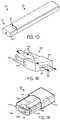
- FIG. 1 Bis a top view of an embodiment of a vaporizer device, showing a vaporizer cartridge separated from a vaporizer device body;
- FIG. 1 Cis a top view of the vaporizer device of FIG. 1 B , showing the vaporizer cartridge coupled to the vaporizer device body;
- FIG. 1 Dis a perspective view of the vaporizer device of FIG. 1 C ;
- FIG. 1 Eis a perspective view of the vaporizer cartridge of FIG. 1 B ;
- FIG. 1 Fis another perspective view of the vaporizer cartridge of FIG. 1 E ;
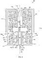
- FIG. 2illustrates a schematic of another embodiment of a vaporizer cartridge.
- Implementations of the current subject matterinclude methods, apparatuses, articles of manufacture, and systems relating to vaporization of one or more materials for inhalation by a user.
- Example implementationsinclude vaporizer devices and systems including vaporizer devices.
- the term “vaporizer device” as used in the following description and claimsrefers to any of a self-contained apparatus, an apparatus that includes two or more separable parts (for example, a vaporizer body that includes a battery and other hardware, and a cartridge that includes a vaporizable material), and/or the like.
- a “vaporizer system,” as used herein,can include one or more components, such as a vaporizer device.
- vaporizer devicesconsistent with implementations of the current subject matter include electronic vaporizers, electronic nicotine delivery systems (ENDS), and/or the like.
- electronic vaporizerselectronic vaporizers
- EDSelectronic nicotine delivery systems
- vaporizer devicesare hand-held devices that heat (such as by convection, conduction, radiation, and/or some combination thereof) a vaporizable material to provide an inhalable dose of the material.
- the vaporizable material used with a vaporizer devicecan be provided within a cartridge (for example, a part of the vaporizer device that contains the vaporizable material in a reservoir or other container) which can be refillable when empty, or disposable such that a new cartridge containing additional vaporizable material of a same or different type can be used).
- a vaporizer devicecan be a cartridge-using vaporizer device, a cartridge-less vaporizer device, or a multi-use vaporizer device capable of use with or without a cartridge.
- a vaporizer devicecan include a heating chamber (for example, an oven or other region in which material is heated by a heating element) configured to receive a vaporizable material directly into the heating chamber, and/or a reservoir or the like for containing the vaporizable material.
- a heating chamberfor example, an oven or other region in which material is heated by a heating element
- a reservoir or the likefor containing the vaporizable material.
- a vaporizer devicecan be configured for use with a liquid vaporizable material (for example, a carrier solution in which an active and/or inactive ingredient(s) are suspended or held in solution, or a liquid form of the vaporizable material itself).
- a liquid vaporizable materialfor example, a carrier solution in which an active and/or inactive ingredient(s) are suspended or held in solution, or a liquid form of the vaporizable material itself.
- the liquid vaporizable materialcan be capable of being completely vaporized. Alternatively, at least a portion of the liquid vaporizable material can remain after all of the material suitable for inhalation has been vaporized.
- a vaporizer device 100can include a power source 112 (for example, a battery, which can be a rechargeable battery), and a controller 104 (for example, a processor, circuitry, etc. capable of executing logic) for controlling delivery of heat to an atomizer 141 to cause a vaporizable material 102 to be converted from a condensed form (such as a liquid, a solution, a suspension, a part of an at least partially unprocessed plant material, etc.) to the gas phase.
- the controller 104can be part of one or more printed circuit boards (PCBs) consistent with certain implementations of the current subject matter.
- At least some of the vaporizable material 102 in the gas phasecan condense to form particulate matter in at least a partial local equilibrium with the gas phase as part of an aerosol, which can form some or all of an inhalable dose provided by the vaporizer device 100 during a user's puff or draw on the vaporizer device 100 .
- the interplay between gas and condensed phases in an aerosol generated by a vaporizer device 100can be complex and dynamic, due to factors such as ambient temperature, relative humidity, chemistry, flow conditions in airflow paths (both inside the vaporizer device and in the airways of a human or other animal), and/or mixing of the vaporizable material 102 in the gas phase or in the aerosol phase with other air streams, which can affect one or more physical parameters of an aerosol.
- the inhalable dosecan exist predominantly in the gas phase (for example, formation of condensed phase particles can be very limited).
- the atomizer 141 in the vaporizer device 100can be configured to vaporize a vaporizable material 102 .
- the vaporizable material 102can be a liquid. Examples of the vaporizable material 102 include neat liquids, suspensions, solutions, mixtures, and/or the like.
- the atomizer 141can include a wicking element (i.e., a wick) configured to convey an amount of the vaporizable material 102 to a part of the atomizer 141 that includes a heating element (not shown in FIG. 1 A ).
- the wicking elementcan be configured to draw the vaporizable material 102 from a reservoir 140 configured to contain the vaporizable material 102 , such that the vaporizable material 102 can be vaporized by heat delivered from a heating element.
- the wicking elementcan also optionally allow air to enter the reservoir 140 and replace the volume of vaporizable material 102 removed.
- capillary actioncan pull vaporizable material 102 into the wick for vaporization by the heating element, and air can return to the reservoir 140 through the wick to at least partially equalize pressure in the reservoir 140 .
- Other methods of allowing air back into the reservoir 140 to equalize pressureare also within the scope of the current subject matter.
- wickor “wicking element” include any material capable of causing fluid motion via capillary pressure.
- the heating elementcan include one or more of a conductive heater, a radiative heater, and/or a convective heater.
- a resistive heating elementwhich can include a material (such as a metal or alloy, for example a nickel-chromium alloy, or a non-metallic resistor) configured to dissipate electrical power in the form of heat when electrical current is passed through one or more resistive segments of the heating element.
- the atomizer 141can include a heating element which includes a resistive coil or other heating element wrapped around, positioned within, integrated into a bulk shape of, pressed into thermal contact with, or otherwise arranged to deliver heat to a wicking element, to cause the vaporizable material 102 drawn from the reservoir 140 by the wicking element to be vaporized for subsequent inhalation by a user in a gas and/or a condensed (for example, aerosol particles or droplets) phase.
- wicking elements, heating elements, and/or atomizer assembly configurationsare also possible.
- the heating elementcan be activated in association with a user puffing (i.e., drawing, inhaling, etc.) on a mouthpiece 130 of the vaporizer device 100 to cause air to flow from an air inlet, along an airflow path that passes the atomizer 141 (i.e., wicking element and heating element).
- aircan flow from an air inlet through one or more condensation areas or chambers, to an air outlet in the mouthpiece 130 .
- Incoming air moving along the airflow pathmoves over or through the atomizer 141 , where vaporizable material 102 in the gas phase is entrained into the air.
- the heating elementcan be activated via the controller 104 , which can optionally be a part of a vaporizer body 110 as discussed herein, causing current to pass from the power source 112 through a circuit including the resistive heating element, which is optionally part of a vaporizer cartridge 120 as discussed herein.
- the entrained vaporizable material 102 in the gas phasecan condense as it passes through the remainder of the airflow path such that an inhalable dose of the vaporizable material 102 in an aerosol form can be delivered from the air outlet (for example, the mouthpiece 130 ) for inhalation by a user.
- Activation of the heating elementcan be caused by automatic detection of a puff based on one or more signals generated by one or more of a sensor 113 .
- the sensor 113 and the signals generated by the sensor 113can include one or more of: a pressure sensor or sensors disposed to detect pressure along the airflow path relative to ambient pressure (or optionally to measure changes in absolute pressure), a motion sensor or sensors (for example, an accelerometer) of the vaporizer device 100 , a flow sensor or sensors of the vaporizer device 100 , a capacitive lip sensor of the vaporizer device 100 , detection of interaction of a user with the vaporizer device 100 via one or more input devices 116 (for example, buttons or other tactile control devices of the vaporizer device 100 ), receipt of signals from a computing device in communication with the vaporizer device 100 , and/or via other approaches for determining that a puff is occurring or imminent.
- a pressure sensor or sensorsdisposed to detect pressure along the airflow path relative to ambient pressure (or optionally to measure changes in absolute pressure
- the vaporizer device 100can be configured to connect (such as, for example, wirelessly or via a wired connection) to a computing device (or optionally two or more devices) in communication with the vaporizer device 100 .
- the controller 104can include communication hardware 105 .
- the controller 104can also include a memory 108 .
- the communication hardware 105can include firmware and/or can be controlled by software for executing one or more cryptographic protocols for the communication.
- a computing devicecan be a component of a vaporizer system that also includes the vaporizer device 100 , and can include its own hardware for communication, which can establish a wireless communication channel with the communication hardware 105 of the vaporizer device 100 .
- a computing device used as part of a vaporizer systemcan include a general-purpose computing device (such as a smartphone, a tablet, a personal computer, some other portable device such as a smartwatch, or the like) that executes software to produce a user interface for enabling a user to interact with the vaporizer device 100 .
- such a device used as part of a vaporizer systemcan be a dedicated piece of hardware such as a remote control or other wireless or wired device having one or more physical or soft (i.e., configurable on a screen or other display device and selectable via user interaction with a touch-sensitive screen or some other input device like a mouse, pointer, trackball, cursor buttons, or the like) interface controls.
- the vaporizer device 100can also include one or more outputs 117 or devices for providing information to the user.
- the outputs 117can include one or more light emitting diodes (LEDs) configured to provide feedback to a user based on a status and/or mode of operation of the vaporizer device 100 .
- LEDslight emitting diodes
- the computing deviceexecutes one or more computer instruction sets to provide a user interface and underlying data handling.
- detection by the computing device of user interaction with one or more user interface elementscan cause the computing device to signal the vaporizer device 100 to activate the heating element to reach an operating temperature for creation of an inhalable dose of vapor/aerosol.
- Other functions of the vaporizer device 100can be controlled by interaction of a user with a user interface on a computing device in communication with the vaporizer device 100 .
- the temperature of a resistive heating element of the vaporizer device 100can depend on a number of factors, including an amount of electrical power delivered to the resistive heating element and/or a duty cycle at which the electrical power is delivered, conductive heat transfer to other parts of the electronic vaporizer device 100 and/or to the environment, latent heat losses due to vaporization of the vaporizable material 102 from the wicking element and/or the atomizer 141 as a whole, and convective heat losses due to airflow (i.e., air moving across the heating element or the atomizer 141 as a whole when a user inhales on the vaporizer device 100 ).
- the vaporizer device 100may, in some implementations of the current subject matter, make use of signals from the sensor 113 (for example, a pressure sensor) to determine when a user is inhaling.
- the sensor 113can be positioned in the airflow path and/or can be connected (for example, by a passageway or other path) to an airflow path containing an inlet for air to enter the vaporizer device 100 and an outlet via which the user inhales the resulting vapor and/or aerosol such that the sensor 113 experiences changes (for example, pressure changes) concurrently with air passing through the vaporizer device 100 from the air inlet to the air outlet.
- the heating elementcan be activated in association with a user's puff, for example by automatic detection of the puff, or by the sensor 113 detecting a change (such as a pressure change) in the airflow path.
- the sensor 113can be positioned on or coupled to (i.e., electrically or electronically connected, either physically or via a wireless connection) the controller 104 (for example, a printed circuit board assembly or other type of circuit board).
- the controller 104for example, a printed circuit board assembly or other type of circuit board.
- the seal 127which can be a gasket, can be configured to at least partially surround the sensor 113 such that connections of the sensor 113 to the internal circuitry of the vaporizer device 100 are separated from a part of the sensor 113 exposed to the airflow path.
- the seal 127can also separate parts of one or more electrical connections between the vaporizer body 110 and the vaporizer cartridge 120 .
- Such arrangements of the seal 127 in the vaporizer device 100can be helpful in mitigating against potentially disruptive impacts on vaporizer components resulting from interactions with environmental factors such as water in the vapor or liquid phases, other fluids such as the vaporizable material 102 , etc., and/or to reduce the escape of air from the designated airflow path in the vaporizer device 100 .
- Unwanted air, liquid or other fluid passing and/or contacting circuitry of the vaporizer device 100can cause various unwanted effects, such as altered pressure readings, and/or can result in the buildup of unwanted material, such as moisture, excess vaporizable material 102 , etc., in parts of the vaporizer device 100 where they can result in poor pressure signal, degradation of the sensor 113 or other components, and/or a shorter life of the vaporizer device 100 .
- Leaks in the seal 127can also result in a user inhaling air that has passed over parts of the vaporizer device 100 containing, or constructed of, materials that may not be desirable to be inhaled.
- the vaporizer body 110includes the controller 104 , the power source 112 (for example, a battery), one more of the sensor 113 , charging contacts (such as those for charging the power source 112 ), the seal 127 , and a cartridge receptacle 118 configured to receive the vaporizer cartridge 120 for coupling with the vaporizer body 110 through one or more of a variety of attachment structures.
- the vaporizer cartridge 120includes the reservoir 140 for containing the vaporizable material 102 , and the mouthpiece 130 has an aerosol outlet for delivering an inhalable dose to a user.
- the vaporizer cartridge 120can include the atomizer 141 having a wicking element and a heating element.
- the wicking element and the heating elementcan be part of the vaporizer body 110 .
- the vaporizer device 100can be configured to supply vaporizable material 102 from the reservoir 140 in the vaporizer cartridge 120 to the part(s) of the atomizer 141 included in the vaporizer body 110 .
- the vaporizer device 100can include electrical connection features (for example, means for completing a circuit) for completing a circuit that includes the controller 104 (for example, a printed circuit board, a microcontroller, or the like), the power source 112 , and the heating element (for example, a heating element within the atomizer 141 ).
- electrical connection featuresfor example, means for completing a circuit
- the controller 104for example, a printed circuit board, a microcontroller, or the like
- the power source 112for example, a heating element within the atomizer 141 .
- These featurescan include one or more contacts (referred to herein as cartridge contacts 124 a and 124 b ) on a bottom surface of the vaporizer cartridge 120 and at least two contacts (referred to herein as receptacle contacts 125 a and 125 b ) disposed near a base of the cartridge receptacle 118 of the vaporizer device 100 such that the cartridge contacts 124 a and 124 b and the receptacle contacts 125 a and 125 b make electrical connections when the vaporizer cartridge 120 is inserted into and coupled with the cartridge receptacle 118 .
- the circuit completed by these electrical connectionscan allow delivery of electrical current to a heating element and can further be used for additional functions, such as measuring a resistance of the heating element for use in determining and/or controlling a temperature of the heating element based on a thermal coefficient of resistivity of the heating element.
- the cartridge contacts 124 a and 124 b and the receptacle contacts 125 a and 125 bcan be configured to electrically connect in either of at least two orientations.
- one or more circuits necessary for operation of the vaporizer device 100can be completed by insertion of the vaporizer cartridge 120 into the cartridge receptacle 118 in a first rotational orientation (around an axis along which the vaporizer cartridge 120 is inserted into the cartridge receptacle 118 of the vaporizer body 110 ) such that the cartridge contact 124 a is electrically connected to the receptacle contact 125 a and the cartridge contact 124 b is electrically connected to the receptacle contact 125 b .
- the one or more circuits necessary for operation of the vaporizer device 100can be completed by insertion of the vaporizer cartridge 120 in the cartridge receptacle 118 in a second rotational orientation such cartridge contact 124 a is electrically connected to the receptacle contact 125 b and cartridge contact 124 b is electrically connected to the receptacle contact 125 a.
- the vaporizer cartridge 120 or at least the insertable end 122 of the vaporizer cartridge 120can be symmetrical upon a rotation of 180° around an axis along which the vaporizer cartridge 120 is inserted into the cartridge receptacle 118 .
- the circuitry of the vaporizer device 100can support identical operation regardless of which symmetrical orientation of the vaporizer cartridge 120 occurs.
- the vaporizer body 110includes one or more detents (for example, dimples, protrusions, etc.) protruding inwardly from an inner surface of the cartridge receptacle 118 , additional material (such as metal, plastic, etc.) formed to include a portion protruding into the cartridge receptacle 118 , and/or the like.
- detentsfor example, dimples, protrusions, etc.
- additional materialsuch as metal, plastic, etc.
- One or more exterior surfaces of the vaporizer cartridge 120can include corresponding recesses (not shown in FIG.
- the vaporizer cartridge 120 and the vaporizer body 110are coupled (e.g., by insertion of the vaporizer cartridge 120 into the cartridge receptacle 118 of the vaporizer body 110 ), the detents or protrusions of the vaporizer body 110 can fit within and/or otherwise be held within the recesses of the vaporizer cartridge 120 , to hold the vaporizer cartridge 120 in place when assembled.
- Such an assemblycan provide enough support to hold the vaporizer cartridge 120 in place to ensure good contact between the cartridge contacts 124 a and 124 b and the receptacle contacts 125 a and 125 b , while allowing release of the vaporizer cartridge 120 from the vaporizer body 110 when a user pulls with reasonable force on the vaporizer cartridge 120 to disengage the vaporizer cartridge 120 from the cartridge receptacle 118 .
- the vaporizer cartridge 120can have a non-circular cross section transverse to the axis along which the vaporizer cartridge 120 is inserted into the cartridge receptacle 118 .
- the non-circular cross sectioncan be approximately rectangular, approximately elliptical (i.e., have an approximately oval shape), non-rectangular but with two sets of parallel or approximately parallel opposing sides (i.e., having a parallelogram-like shape), or other shapes having rotational symmetry of at least order two.
- approximate shapeindicates that a basic likeness to the described shape is apparent, but that sides of the shape in question need not be completely linear and vertices need not be completely sharp. Rounding of both or either of the edges or the vertices of the cross-sectional shape is contemplated in the description of any non-circular cross section referred to herein.
- the cartridge contacts 124 a and 124 b and the receptacle contacts 125 a and 125 bcan take various forms.
- one or both sets of contactscan include conductive pins, tabs, posts, receiving holes for pins or posts, or the like.
- Some types of contactscan include springs or other features to facilitate better physical and electrical contact between the contacts on the vaporizer cartridge 120 and the vaporizer body 110 .
- the electrical contactscan optionally be gold-plated, and/or include other materials.
- FIGS. 1 B- 1 Dillustrate an embodiment of the vaporizer body 110 having a cartridge receptacle 118 into which the vaporizer cartridge 120 can be releasably inserted.
- FIGS. 1 B and 1 Cshow top views of the vaporizer device 100 illustrating the vaporizer cartridge 120 being positioned for insertion and inserted, respectively, into the vaporizer body 110 .
- FIG. 1 Dillustrates the reservoir 140 of the vaporizer cartridge 120 being formed in whole or in part from translucent material such that a level of the vaporizable material 102 is visible from a window 132 (e.g., translucent material) along the vaporizer cartridge 120 .
- a window 132e.g., translucent material
- the vaporizer cartridge 120can be configured such that the window 132 remains visible when insertably received by the vaporizer cartridge receptacle 118 of the vaporizer body 110 .
- the window 132can be disposed between a bottom edge of the mouthpiece 130 and a top edge of the vaporizer body 110 when the vaporizer cartridge 120 is coupled with the cartridge receptacle 118 .
- FIG. 1 Eillustrates an example airflow path 134 created during a puff by a user on the vaporizer device 100 .
- the airflow path 134can direct air to a vaporization chamber 150 (see FIG. 1 F ) contained in a wick housing where the air is combined with inhalable aerosol for delivery to a user via a mouthpiece 130 , which can also be part of the vaporizer cartridge 120 .
- a vaporization chamber 150see FIG. 1 F
- a wick housingwhere the air is combined with inhalable aerosol for delivery to a user via a mouthpiece 130 , which can also be part of the vaporizer cartridge 120 .
- aircan pass between an outer surface of the vaporizer cartridge 120 (for example, window 132 shown in FIG. 1 D ) and an inner surface of the cartridge receptacle 118 on the vaporizer body 110 .
- Aircan then be drawn into the insertable end 122 of the vaporizer cartridge 120 , through the vaporization chamber 150 that includes or contains the heating element and wick, and out through an outlet 136 of the mouthpiece 130 for delivery of the inhalable aerosol to a user.
- this configurationcauses air to flow down around the insertable end 122 of the vaporizer cartridge 120 into the cartridge receptacle 118 and then flow back in the opposite direction after passing around the insertable end 122 (e.g., an end opposite of the end including the mouthpiece 130 ) of the vaporizer cartridge 120 as it enters into the cartridge body toward the vaporization chamber 150 .
- the airflow path 134then travels through the interior of the vaporizer cartridge 120 , for example via one or more tubes or internal channels (such as cannula 128 shown in FIG. 1 F ) and through one or more outlets (such as outlet 136 ) formed in the mouthpiece 130 .
- the mouthpiece 130can be a separable component of the vaporizer cartridge 120 or can be integrally formed with other component(s) of the vaporizer cartridge 120 (for example, formed as a unitary structure with the reservoir 140 and/or the like).
- FIG. 1 Fshows additional features that can be included in the vaporizer cartridge 120 consistent with implementations of the current subject matter.
- the vaporizer cartridge 120can include a plurality of cartridge contacts (such as cartridge contacts 124 a , 124 b ) disposed on the insertable end 122 .
- the cartridge contacts 124 a , 124 bcan optionally each be part of a single piece of metal that forms a conductive structure (such as conductive structure 126 ) connected to one of two ends of a resistive heating element.
- the conductive structurecan optionally form opposing sides of a heating chamber and can act as heat shields and/or heat sinks to reduce transmission of heat to outer walls of the vaporizer cartridge 120 .
- FIG. 1 Falso shows the cannula 128 within the vaporizer cartridge 120 that defines part of the airflow path 134 between the heating chamber formed between the conductive structure 126 and the mouthpiece 130 .
- the vaporizer cartridges described hereinare designed to store a plurality of particles of vaporizable material in a reservoir in which the particles are configured to be selectively melted or ruptured in response to an event (e.g., heating, mechanical interaction, chemical interaction, and the like).
- the melting or rupturing of these particlesare configured to provide an on-demand delivery of liquid vaporizable material to form a vapor for inhalation by a user of a vaporization device.
- On-demand delivery of liquid vaporizable material for vaporization through melting or rupturing of particlesinhibits undesirable leakage and provides the ability to use a storage medium that can effectively delivery liquid vaporizable material throughout the lifetime of the vaporizer cartridge.
- the cartridgesgenerally include a reservoir and an airflow tube that includes a wicking element that is in communication with the reservoir.
- the reservoiris configured to contain a plurality of particles that contain a volume of a vaporizable material.
- the plurality of particlescan have any suitable particle size (e.g., from about 10 nm to 1 mm, or other sizes that achieve one or more advantages as described herein).
- the distribution of the plurality of particles within the reservoircan adopt any desired distribution such as, for example, Gaussian, multi-modal, and/or the like.
- the wicking elementis configured to at least draw a portion of a liquid vaporizable material into the airflow tube for vaporization.
- the wicking elementcan be formed of any suitable material that can draw the liquid vaporizable material in the airflow tube, e.g., by capillary action.
- suitable materials for the wicking elementcan include of one or more ceramic materials, one or more cottons, or one or more polymers.
- the wicking elementis formed of one or more ceramic materials.
- Such drawing of the liquid vaporizable material into the airflow tubecan be due, at least in part, to capillary action provided by the wicking element, which pulls the vaporizable material along the wick in the direction of the airflow tube.
- the liquid vaporizable materialis formed by selectively melting or rupturing of some amount of the plurality of particles.
- the wicking elementcan also be configured to receive at least a portion of the liquid vaporizable material under the influence of gravity.
- the plurality of particlescan be in the form of encapsulated particles that include a core and a coating material that forms a shell about the core.
- the coreis formed of a liquid vaporizable material.
- the shellsare configured to be selectively ruptured within the cartridge to release the liquid vaporizable material therefrom such that the wicking element can draw a portion thereof into the airflow tube for vaporization.
- the coating materialcan be any suitable material that can effectively form a shell that can house the liquid vaporizable material described herein while also being capable of being selectively ruptured when desired.
- the encapsulated particlescan be formed using any known suitable encapsulation method.
- the wicking elementcan be further configured to substantially draw at least a portion of ruptured shells into the airflow tube for vaporization.
- the vaporization of the portion of the ruptured shells drawn into the airflow tubeoccurs concurrently with the vaporization of the liquid vaporizable material.
- the shellscan be configured to be thermally ruptured, mechanically ruptured, chemically ruptured, or any combination thereof.
- the shellscan be thermally ruptured in response to bulk heating of the wicking element.
- the heated wicking elementcan dissipate heat into the reservoir to which at least a portion of the plurality of encapsulated particles are exposed thereto.
- the portion of the shells that are exposed to the heatcan be within a predetermined distance of the wicking element. This heat exposure can cause the exposed shells of the plurality of encapsulated particles to substantially melt, thereby releasing their respective portions of the liquid vaporizable material.
- the released liquid vaporizable materialcan be drawn into the wicking element, and ultimately vaporized into vaporized material.
- the wicking elementcan be bulk heated using any suitable known technique.
- the wicking elementcan be heated via ohmic heating, capacitive heating, and the like.
- the wicking elementcan be heated by a separate heating element.
- the wicking elementcan be heated in response to receiving an electric current itself from a power source.
- the wicking elementcan be heated in response to an electrical potential being created across it (e.g., between two metal plates on opposing sides of the wicking element).
- the shellscan be mechanically ruptured, for example, by coming into contact with at least one surface of the wicking element that is roughened, e.g., to include one or more spikes, or other abrasive features, etc., so that the shells of the encapsulated particles rupture upon coming into contact with at least a portion of such roughened surface.
- at least a portion of the inner surface of the reservoircan be roughened, e.g., to include one or more spikes, or other abrasive features, etc., so that the shells of the encapsulated particles rupture upon coming into contact with at least a portion of the roughened surface of the reservoir.
- the shellscan be chemically ruptured by coming into contact with the wicking element itself.
- the wicking elementcan be formed of a material that is configured to chemically interact with the shells such that at least a portion of the shells breakdown, and therefore release their respective portions of the liquid vaporizable material therefrom.
- the shellscan come into contact with an interference material that is configured to chemically interact with, and cause the breakdown of, the shells.
- the interference materialcan be added directly to or in close proximity with the wicking element.
- the plurality of particlescan be in the form of substantially solid vaporizable material that are configured to be selectively melted to form a liquid vaporizable material such that the wicking element can draw a portion thereof into the airflow tube for vaporization.
- the substantially solid vaporizable materialcan be substantially melted in response to bulk heating of the wicking element, such as the bulk heating discussed above.
- the heated wicking elementcan dissipate heat into the reservoir to which at least a portion of the plurality of particles are exposed thereto.
- the portion of the particles that are exposed to the heatcan be within a predetermined distance of the wicking element. This heat exposure can cause the exposed particles to substantially melt, thereby undergoing a phase change to form liquid vaporizable material.
- the portion of the plurality of particles that are substantially meltedare within a predetermined distance of the wicking element.
- the liquid vaporizable materialcan then be drawn into the wicking element, and ultimately vaporized into vaporized material.
- the liquid vaporizable materialcan be substantially vaporized by the wicking element itself, either by the same amount of heat provided to substantially cause the solid to liquid phase change or by an additional amount of heat provided by the wicking element.
- the liquid vaporizable materialcan be substantially vaporized by a separate heating element.
- cartridgesare shown and described in connection with a plurality of particles of vaporizable material, a person skilled in the art will appreciate that these cartridges can be used in connection with vaporizable material in other shapes and sizes. Moreover, the implementation of storing a plurality of particles that are configured for on-demand liquid vaporizable material formation is not limited to the cartridges shown and described herein.
- FIG. 2illustrates an exemplary vaporizer cartridge 200 that can be selectively coupled to and removable from a vaporizer body, such as vaporizer body 110 shown in FIGS. 1 A- 1 D .
- the cartridge 200includes a reservoir 202 configured to contain a plurality of encapsulated particles 204 and an airflow tube 206 extending through the reservoir 202 .
- the cartridge 200can be configured to contain a plurality of particles formed of substantially solid vaporizable material. For purposes of simplicity, certain components of the cartridge 200 are not illustrated.
- each encapsulated particleincludes a core and a coating material in which the core is formed of a liquid vaporizable material. While the plurality of encapsulated particles are illustrated as being dispersed throughout the reservoir 202 , a person skilled in the art will appreciate that the particles may be, for example, packed within the reservoir 202 at any desired porosity and location. Thus, a porosity with interstices between the encapsulated particles can be tailored to a desired value. In some embodiments, such interstices can be filled with air. Further, the encapsulated particles may possess a selective distribution of sizes, for example, the distribution illustrated in FIG. 2 .
- the reservoir 202can have a variety of shapes and sizes, the reservoir 202 , as shown in FIG. 2 , is substantially rectangular in shape.
- the reservoir 202can include at least one vent 208 that is configured to substantially allow the passage of air into the reservoir 202 from the environment to thereby substantially maintain an inner pressure (e.g., an inner pressure that is substantially equal to ambient pressure) of the reservoir 202 .
- the at least one vent 208can function as a one-way valve and therefore can be used to decrease or eliminate negative pressure that is created within the reservoir 202 (e.g., as liquid vaporizable material flows out of the reservoir 202 ).
- the at least one vent 208can also have a diameter that is less than the diameter(s) of the encapsulated particles so as substantially prevent the encapsulated particles from exiting the reservoir 202 through the at least one vent 208 .
- airflow tube 206is shown to be approximately centered within respect to a longitudinal axis (L) extending through a centroid of the reservoir 202 , such position is not required. As such, other locations of the airflow tube 206 within the reservoir 202 are also contemplated herein. Further, other airflow configurations through the reservoir 202 are also contemplated herein.
- the airflow tube 206can have a variety of configurations.
- the airflow tubeextends a length (LA) from a first end 206 a to a second end 206 b and is defined by a curved sidewall 207 .
- LAlength
- the airflow tube 206is illustrated as being open at its first and second ends 206 a , 206 b , in other embodiments, the airflow tube 26 can also be defined by a bottom wall at the second end 206 b of the airflow tube 206 . This bottom wall can be configured to substantially allow air to pass therethrough and into the airflow tube 206 .
- the airflow tube 206defines a passageway 210 that extends therethrough and into communication with an outlet tube 212 of a mouthpiece 214 of the cartridge 200 .
- the outlet tube 212extends from and is in communication with an outlet 214 a of the mouthpiece 214 .
- the passageway 210is configured to direct air, illustrated as arrow 216 , through the airflow tube 206 so that the air 216 will mix with vaporized material to form an aerosol, illustrated as arrow 225 , as discussed in more detail below.
- the passageway 210further directs the aerosol 225 through the first end 206 a (e.g., an outlet) of the airflow tube 206 , and thus into a mouthpiece 214 that is coupled to the vaporizer cartridge 200 , for inhalation by a user.
- the mouthpiececan have a variety of configurations and therefore is not limited to what is illustrated in FIG. 2 . While a mouthpiece 214 is shown in FIG. 2 , a person skilled in the art will appreciate that in other embodiments, the mouthpiece 214 can be omitted and the user can directly puff on the cartridge 200 at an outlet (such as the first end 206 a of the airflow tube 206 ).
- the airflow tube 206includes a wicking element 218 .
- the wicking element 218is configured to draw a portion of liquid vaporizable material into the airflow tube 206 for vaporization when at least a portion of the plurality of encapsulated particles 204 are ruptured.
- the wicking element 218can also be further configured to be selectively bulk heated so as to thermally rupture a portion of the shells of the plurality of encapsulated particles 204 to release the liquid vaporizable material therefrom.
- the wicking element 218can have a variety of configurations, the wicking element 218 is substantially rectangular.
- the wicking element 218extends substantially laterally across the airflow tube 206 (e.g., substantially perpendicular to the length (LA) of the airflow tube 206 ) such that a first and a second opposing end 218 a , 218 b of the wicking element 218 are each positioned within the reservoir 202 .
- the wicking element 218is in fluid communication with the reservoir 202 .
- liquid vaporizable materialIn use, once liquid vaporizable material is drawn into the airflow tube 206 via the wicking element 218 , as discussed above, it can be substantially vaporized into vaporized material via heating element 221 , as discussed in more detail below.
- the vaporized materialmixes with the air 216 passing through the passageway 210 to form the aerosol 225 and is carried out of the airflow tube 206 and into the outlet tube 212 and ultimately through the outlet 214 a of the mouthpiece 214 for inhalation by a user.
- the vaporizer cartridge 200includes a heating element 221 disposed within the airflow tube 206 .
- the heating element 221is configured to vaporize at least a portion of the vaporizable material drawn into the wicking element 218 , and thus into the airflow tube 206 .
- the heating element 221can be or include one or more of a conductive heater, a radiative heater, and a convective heater.
- one type of heating elementis a resistive heating element, such as a resistive coil, which can be constructed of or at least include a material (e.g., a metal or alloy, for example a nickel-chromium alloy, or a non-metallic resistor) configured to dissipate electrical power in the form of heat when electrical current is passed through one or more resistive segments of the heating element.
- a resistive heating elementsuch as a resistive coil
- a materiale.g., a metal or alloy, for example a nickel-chromium alloy, or a non-metallic resistor
- the vaporizer cartridge 200includes two or more cartridge contacts such as, for example, a first cartridge contact 223 a and a second cartridge contact 223 b .
- the two or more cartridge contactscan be configured to couple, for example, with the receptacle contacts 125 a and 125 b in order to form one or more electrical connections with the vaporizer body 110 .
- the circuit completed by these electrical connectionscan allow delivery of electrical current to the heating element 221 .
- the circuitcan also serve additional functions such as, for example, measuring a resistance of the heating element 221 for use in determining and/or controlling a temperature of the heating element 221 based on a thermal coefficient of resistivity of the heating element 221 .
- the cartridge 200can also include a spit-catch element 220 that is disposed within the airflow tube 206 .
- the spit-catch element 220can be configured to prevent the ingress of external material (e.g., saliva and/or the like) into passageway 210 including by capturing the external material. While the spit-catch element can be disposed within any portion of the airflow tube 206 , the spit-catch element 220 is disposed proximate to the first end 206 a of the airflow tube 206 .
- the spit-catch element 220can have a variety of configurations. As shown, the spit-catch element 200 is substantially cylindrical and coupled to the curved sidewall 207 of the airflow tube 206 .
- the cartridge 200can also include an attachment structure 222 for coupling to a vaporizer body, such as vaporizer body 110 ( FIGS. 1 A- 1 D ).
- the attachment structure 222 of the cartridge 200is a male coupling element
- the attachment structure 222 of the cartridge 200is a female coupling element.
- the attachment structure 222is a male coupling element that is in the form of a protrusion that is configured to be received within a female coupling element (e.g., recess) that can fit and/or otherwise snap over such protrusions when an end 200 a of the cartridge 200 is inserted into a vaporizer body.
- suitable attachment structuresare contemplated herein, e.g., structures that are configured for a friction fit. It is also contemplated herein that a spit-catch element and/or an attachment structure can be omitted.
- the term “substantially”is utilized herein to represent the inherent degree of uncertainty that may be attributed to any quantitative comparison, value, measurement, or other representation.
- the term “substantially”is also utilized herein to represent the degree by which a quantitative representation may vary from a stated reference without resulting in a change in the basic function of the subject matter at issue.
- references to a structure or feature that is disposed “adjacent” another featuremay have portions that overlap or underlie the adjacent feature.
- phrases such as “at least one of” or “one or more of”may occur followed by a conjunctive list of elements or features.
- the term “and/or”may also occur in a list of two or more elements or features. Unless otherwise implicitly or explicitly contradicted by the context in which it used, such a phrase is intended to mean any of the listed elements or features individually or any of the recited elements or features in combination with any of the other recited elements or features.
- the phrases “at least one of A and B;” “one or more of A and B;” and “A and/or B”are each intended to mean “A alone, B alone, or A and B together.”
- a similar interpretationis also intended for lists including three or more items.
- the phrases “at least one of A, B, and C;” “one or more of A, B, and C;” and “A, B, and/or C”are each intended to mean “A alone, B alone, C alone, A and B together, A and C together, B and C together, or A and B and C together.”
- Use of the term “based on,” above and in the claimsis intended to mean, “based at least in part on,” such that an unrecited feature or element is also permissible.
- spatially relative termssuch as “forward”, “rearward”, “under”, “below”, “lower”, “over”, “upper” and the like, may be used herein for ease of description to describe one element or feature's relationship to another element(s) or feature(s) as illustrated in the figures. It will be understood that the spatially relative terms are intended to encompass different orientations of the device in use or operation in addition to the orientation depicted in the figures. For example, if a device in the figures is inverted, elements described as “under” or “beneath” other elements or features would then be oriented “over” the other elements or features. Thus, the exemplary term “under” can encompass both an orientation of over and under.
- the devicemay be otherwise oriented (rotated 90 degrees or at other orientations) and the spatially relative descriptors used herein interpreted accordingly.
- the terms “upwardly”, “downwardly”, “vertical”, “horizontal” and the likeare used herein for the purpose of explanation only unless specifically indicated otherwise.
- first and secondmay be used herein to describe various features/elements (including steps), these features/elements should not be limited by these terms, unless the context indicates otherwise. These terms may be used to distinguish one feature/element from another feature/element. Thus, a first feature/element discussed below could be termed a second feature/element, and similarly, a second feature/element discussed below could be termed a first feature/element without departing from the teachings provided herein.
- a numeric valuemay have a value that is +/ ⁇ 0.1% of the stated value (or range of values), +/ ⁇ 1% of the stated value (or range of values), +/ ⁇ 2% of the stated value (or range of values), +/ ⁇ 5% of the stated value (or range of values), +/ ⁇ 10% of the stated value (or range of values), etc.
- Any numerical values given hereinshould also be understood to include about or approximately that value, unless the context indicates otherwise. For example, if the value “10” is disclosed, then “about 10” is also disclosed. Any numerical range recited herein is intended to include all sub-ranges subsumed therein.
- One or more aspects or features of the subject matter described hereincan be realized in digital electronic circuitry, integrated circuitry, specially designed application specific integrated circuits (ASICs), field programmable gate arrays (FPGAs) computer hardware, firmware, software, and/or combinations thereof.
- ASICsapplication specific integrated circuits
- FPGAsfield programmable gate arrays
- These various aspects or featurescan include implementation in one or more computer programs that are executable and/or interpretable on a programmable system including at least one programmable processor, which can be special or general purpose, coupled to receive data and instructions from, and to transmit data and instructions to, a storage system, at least one input device, and at least one output device.
- the programmable system or computing systemmay include clients and servers.
- a client and serverare generally remote from each other and typically interact through a communication network. The relationship of client and server arises by virtue of computer programs running on the respective computers and having a client-server relationship to each other.
- machine-readable signalrefers to any signal used to provide machine instructions and/or data to a programmable processor.
- the machine-readable mediumcan store such machine instructions non-transitorily, such as for example as would a non-transient solid-state memory or a magnetic hard drive or any equivalent storage medium.
- the machine-readable mediumcan alternatively or additionally store such machine instructions in a transient manner, such as for example, as would a processor cache or other random access memory associated with one or more physical processor cores.
Landscapes
- Catching Or Destruction (AREA)
Abstract
Description
Claims (20)
Priority Applications (1)
| Application Number | Priority Date | Filing Date | Title |
|---|---|---|---|
| US16/677,121US11553734B2 (en) | 2018-11-08 | 2019-11-07 | Cartridges for vaporizer devices |
Applications Claiming Priority (2)
| Application Number | Priority Date | Filing Date | Title |
|---|---|---|---|
| US201862757262P | 2018-11-08 | 2018-11-08 | |
| US16/677,121US11553734B2 (en) | 2018-11-08 | 2019-11-07 | Cartridges for vaporizer devices |
Publications (2)
| Publication Number | Publication Date |
|---|---|
| US20200146360A1 US20200146360A1 (en) | 2020-05-14 |
| US11553734B2true US11553734B2 (en) | 2023-01-17 |
Family
ID=68808511
Family Applications (1)
| Application Number | Title | Priority Date | Filing Date |
|---|---|---|---|
| US16/677,121Active2041-03-27US11553734B2 (en) | 2018-11-08 | 2019-11-07 | Cartridges for vaporizer devices |
Country Status (3)
| Country | Link |
|---|---|
| US (1) | US11553734B2 (en) |
| EP (1) | EP3876760B1 (en) |
| WO (1) | WO2020097341A1 (en) |
Cited By (1)
| Publication number | Priority date | Publication date | Assignee | Title |
|---|---|---|---|---|
| US20210307401A1 (en)* | 2018-12-31 | 2021-10-07 | Juul Labs, Inc. | Cartridges for Vaporizer Devices |
Families Citing this family (6)
| Publication number | Priority date | Publication date | Assignee | Title |
|---|---|---|---|---|
| GB201605105D0 (en) | 2016-03-24 | 2016-05-11 | Nicoventures Holdings Ltd | Vapour provision apparatus |
| GB201605100D0 (en)* | 2016-03-24 | 2016-05-11 | Nicoventures Holdings Ltd | Vapour provision system |
| GB201605101D0 (en) | 2016-03-24 | 2016-05-11 | Nicoventures Holdings Ltd | Electronic vapour provision system |
| US10314340B2 (en)* | 2017-04-21 | 2019-06-11 | Rai Strategic Holdings, Inc. | Refillable aerosol delivery device and related method |
| US12153060B2 (en)* | 2019-01-07 | 2024-11-26 | Luxcan Innovations S.A. | Device and method for extracting and aspirating active substances, especially from the cannabis plant |
| ES2968513T3 (en)* | 2019-03-08 | 2024-05-10 | Jt Int Sa | Electronic cigarette with audible connection |
Citations (284)
| Publication number | Priority date | Publication date | Assignee | Title |
|---|---|---|---|---|
| GB1065678A (en) | 1964-11-10 | 1967-04-19 | Super Temp Corp | Smoking elements and devices |
| US4648393A (en) | 1984-11-02 | 1987-03-10 | Ackrad Laboratories, Inc. | Breath activated medication spray |
| US4708151A (en) | 1986-03-14 | 1987-11-24 | R. J. Reynolds Tobacco Company | Pipe with replaceable cartridge |
| US4793365A (en) | 1984-09-14 | 1988-12-27 | R. J. Reynolds Tobacco Company | Smoking article |
| US4819665A (en) | 1987-01-23 | 1989-04-11 | R. J. Reynolds Tobacco Company | Aerosol delivery article |
| EP0336457A2 (en) | 1985-08-26 | 1989-10-11 | R.J. Reynolds Tobacco Company | Smoking article |
| US4924883A (en) | 1987-03-06 | 1990-05-15 | R. J. Reynolds Tobacco Company | Smoking article |
| US4938236A (en) | 1989-09-18 | 1990-07-03 | R. J. Reynolds Tobacco Company | Tobacco smoking article |
| US4941483A (en) | 1989-09-18 | 1990-07-17 | R. J. Reynolds Tobacco Company | Aerosol delivery article |
| US5019122A (en) | 1987-08-21 | 1991-05-28 | R. J. Reynolds Tobacco Company | Smoking article with an enclosed heat conductive capsule containing an aerosol forming substance |
| US5042509A (en) | 1984-09-14 | 1991-08-27 | R. J. Reynolds Tobacco Company | Method for making aerosol generating cartridge |
| JPH05115272A (en) | 1991-03-11 | 1993-05-14 | Philip Morris Prod Inc | Flavor/taste generating article |
| US5224498A (en) | 1989-12-01 | 1993-07-06 | Philip Morris Incorporated | Electrically-powered heating element |
| US5388574A (en) | 1993-07-29 | 1995-02-14 | Ingebrethsen; Bradley J. | Aerosol delivery article |
| WO1997012639A1 (en) | 1995-04-12 | 1997-04-10 | Arthur Slutsky | Medicament inhaler |
| US5845649A (en) | 1994-01-26 | 1998-12-08 | Japan Tobacco Inc. | Flavor-tasting article |
| US5865186A (en) | 1997-05-21 | 1999-02-02 | Volsey, Ii; Jack J | Simulated heated cigarette |
| US6062213A (en) | 1998-06-16 | 2000-05-16 | Fuisz Technologies Ltd. | Single unit dose inhalation therapy device |
| US6095153A (en) | 1998-06-19 | 2000-08-01 | Kessler; Stephen B. | Vaporization of volatile materials |
| US6164287A (en) | 1998-06-10 | 2000-12-26 | R. J. Reynolds Tobacco Company | Smoking method |
| US6196218B1 (en) | 1999-02-24 | 2001-03-06 | Ponwell Enterprises Ltd | Piezo inhaler |
| US6344222B1 (en) | 1998-09-03 | 2002-02-05 | Jsr Llc | Medicated chewing gum delivery system for nicotine |
| WO2003082031A1 (en) | 2002-03-22 | 2003-10-09 | Steinberg Dan A | Vaporization pipe with flame filter |
| US6708846B1 (en) | 1999-02-14 | 2004-03-23 | Ing. Erich Pfeiffer Gmbh | Dispenser for flowable media |
| US20040182855A1 (en) | 2002-06-12 | 2004-09-23 | Steris Inc. | Heating apparatus for vaporizer |
| US20050161467A1 (en) | 2002-04-26 | 2005-07-28 | Jones Anthony P. | Medicament dispenser |
| US20050172976A1 (en) | 2002-10-31 | 2005-08-11 | Newman Deborah J. | Electrically heated cigarette including controlled-release flavoring |
| US20050236006A1 (en) | 2004-04-24 | 2005-10-27 | Anderson Cowan | Smoking cessation devices, methods of use and methods of conducting business therewith |
| US20050244521A1 (en) | 2003-11-07 | 2005-11-03 | Strickland James A | Tobacco compositions |
| US20050268909A1 (en) | 2002-07-25 | 2005-12-08 | Bonney Stanley G | Medicament dispenser |
| WO2006022715A1 (en) | 2004-08-12 | 2006-03-02 | Alexza Pharmaceuticals, Inc. | Inhalation actuated percussive ignition system |
| US20060191548A1 (en) | 2003-11-07 | 2006-08-31 | Strickland James A | Tobacco compositions |
| US7243689B2 (en) | 2000-02-11 | 2007-07-17 | Medical Instill Technologies, Inc. | Device with needle penetrable and laser resealable portion and related method |
| US20070169773A1 (en) | 2006-01-23 | 2007-07-26 | Lytesyde, Llc | Medical liquid processor apparatus and method |
| US7290549B2 (en) | 2003-07-22 | 2007-11-06 | R. J. Reynolds Tobacco Company | Chemical heat source for use in smoking articles |
| US20080038363A1 (en) | 2001-05-24 | 2008-02-14 | Zaffaroni Alejandro C | Aerosol delivery system and uses thereof |
| US7434584B2 (en) | 2002-03-22 | 2008-10-14 | Vaporgenie, Llc | Vaporization pipe with flame filter |
| US20090032034A1 (en) | 2002-11-26 | 2009-02-05 | Steinberg Dan A | Vaporization pipe with flame filter |
| JP2009505649A (en) | 2005-08-27 | 2009-02-12 | セラニーズ アセテート リミテッド | Filter tow manufacturing method |
| US20090126746A1 (en) | 2006-01-31 | 2009-05-21 | U.S. Smokless Tobacco Manufacturing Company, a CT corporation | Tobacco Articles and Methods |
| US20090192443A1 (en) | 2008-10-06 | 2009-07-30 | Collins Jr James F | Ophthalmic fluid delivery device and method of operation |
| US7581540B2 (en) | 2004-08-12 | 2009-09-01 | Alexza Pharmaceuticals, Inc. | Aerosol drug delivery device incorporating percussively activated heat packages |
| US20090230117A1 (en) | 2008-03-14 | 2009-09-17 | Philip Morris Usa Inc. | Electrically heated aerosol generating system and method |
| US20090255534A1 (en) | 2008-04-11 | 2009-10-15 | Greg Paterno | Sealed Vaporization Cartridge and Vaporization Systems for Using |
| US20090283103A1 (en) | 2008-05-13 | 2009-11-19 | Nielsen Michael D | Electronic vaporizing devices and docking stations |
| US20090293892A1 (en) | 2008-05-30 | 2009-12-03 | Vapor For Life | Portable vaporizer for plant material |
| US20100006092A1 (en) | 2004-08-12 | 2010-01-14 | Alexza Pharmaceuticals, Inc. | Aerosol Drug Delivery Device Incorporating Percussively Activated Heat Packages |
| US20100181387A1 (en) | 2009-12-01 | 2010-07-22 | Zaffaroni Alejandro C | Aerosol delivery system and uses thereof |
| US7832397B2 (en) | 2005-12-28 | 2010-11-16 | Philip Morris Usa Inc. | Aerosol powder delivery device |
| US7913686B2 (en) | 2002-12-19 | 2011-03-29 | Scadds Incorporated | Self contained aerosol dual delivery system (SCADDS) |
| US20110192397A1 (en) | 2008-10-09 | 2011-08-11 | Vectura Delivery Devices Limited | Inhaler |
| US8091558B2 (en) | 2006-01-03 | 2012-01-10 | Gaiatrend Sarl | Cigarette substitute |
| US20120111346A1 (en) | 2009-07-22 | 2012-05-10 | Wedegree Gmbh | Smokeless cigarette substitute product |
| CN102612361A (en) | 2009-09-16 | 2012-07-25 | 菲利普莫里斯生产公司 | Improved device and method for delivery of a medicament |
| US8251060B2 (en) | 2006-11-15 | 2012-08-28 | Perfetti and Perfetti, LLC | Device and method for delivering an aerosol drug |
| US20120248005A1 (en) | 2011-04-01 | 2012-10-04 | Mannkind Corporation | Blister Package for Pharmaceutical Cartridges |
| WO2012164033A1 (en) | 2011-06-01 | 2012-12-06 | British American Tobacco (Investments) Limited | Smoking article |
| US20120312313A1 (en) | 2011-06-07 | 2012-12-13 | Vapor Corp. | Padded cartridge for an electronic smoking apparatus |
| US20130039639A1 (en) | 2012-05-02 | 2013-02-14 | Kevin D. Carney | Vaporizer for water pipe inlet |
| US8387612B2 (en) | 2003-05-21 | 2013-03-05 | Alexza Pharmaceuticals, Inc. | Self-contained heating unit and drug-supply unit employing same |
| WO2013030202A1 (en) | 2011-08-31 | 2013-03-07 | Krapf, Rainer | Device and method for producing aqueous aerosols charged with an active substance |
| US8402976B2 (en) | 2008-04-17 | 2013-03-26 | Philip Morris Usa Inc. | Electrically heated smoking system |
| WO2013089551A1 (en) | 2011-12-15 | 2013-06-20 | Foo Kit Seng | An electronic vaporisation cigarette |
| US8485180B2 (en) | 2008-06-13 | 2013-07-16 | Mannkind Corporation | Dry powder drug delivery system |
| CA2729601C (en) | 2008-02-29 | 2013-09-24 | Yunqiang Xiu | Electronic simulated cigarette & atomization fluid and electronic simulated cigarette utensil & smoke fluid capsule |
| US20130312742A1 (en) | 2011-08-16 | 2013-11-28 | Ploom, Inc. | Low temperature electronic vaporization device and methods |
| US20130327327A1 (en) | 2012-06-06 | 2013-12-12 | Aerodesigns, Inc. | Aerosol dispenser with replaceable cartridge |
| US8714161B2 (en) | 2011-12-29 | 2014-05-06 | Qiuming Liu | Electronic cigarette with solid tobacco substance |
| US20140123989A1 (en) | 2012-11-05 | 2014-05-08 | The Safe Cig, Llc | Device and method for vaporizing a fluid |
| WO2014071747A1 (en) | 2012-11-07 | 2014-05-15 | Xiu Yunqiang | Screw-driven slidable piercing electronic smoking set |
| US8733345B2 (en) | 2006-10-06 | 2014-05-27 | Friedrich Siller | Inhalation device and heating unit therefor |
| US20140150785A1 (en) | 2012-12-05 | 2014-06-05 | Vire, L.L.C. | Electronic cigarette or inhaler |
| US20140178461A1 (en) | 2012-09-21 | 2014-06-26 | Medicon Pharmaceuticals, Inc. | Compounds and compositions for use in the treatment and prevention of lung and brain cancer and precancerous conditions thereof |
| CN103929985A (en) | 2011-10-28 | 2014-07-16 | Jt国际公司 | Apparatus for creating liquid tobacco extract |
| US20140209107A1 (en) | 2013-01-25 | 2014-07-31 | Qiuming Liu | Electronic cigarette |
| US20140209106A1 (en) | 2013-01-25 | 2014-07-31 | Qiuming Liu | Electronic cigarette |
| US8807131B1 (en) | 2013-06-18 | 2014-08-19 | Isonea Limited | Compliance monitoring for asthma inhalers |
| US8813759B1 (en) | 2010-11-18 | 2014-08-26 | Richard C. Horian | Nicotine inhaler and method of manufacture |
| WO2014127446A1 (en) | 2013-02-25 | 2014-08-28 | 9208-8699 Québec Inc. | Handheld electronic vaporization device |
| US8833364B2 (en) | 2008-10-23 | 2014-09-16 | Batmark Limited | Inhaler |
| US20140262871A1 (en) | 2013-03-15 | 2014-09-18 | Altria Client Services Inc. | Display package |
| US20140261479A1 (en) | 2013-03-15 | 2014-09-18 | Altria Client Services Inc. | Nicotine-containing products and methods of making |
| US20140261486A1 (en) | 2013-03-12 | 2014-09-18 | R.J. Reynolds Tobacco Company | Electronic smoking article having a vapor-enhancing apparatus and associated method |
| KR101432877B1 (en) | 2009-03-17 | 2014-09-24 | 필립모리스 프로덕츠 에스.에이. | Tobacco-based nicotine aerosol generation system |
| US8851083B2 (en) | 2005-02-02 | 2014-10-07 | Oglesby & Butler Research & Development Limited | Device for vaporising vaporisable matter |
| US20140301721A1 (en) | 2011-10-25 | 2014-10-09 | Philip Morris Products S.A. | Aerosol generating device with heater assembly |
| US20140321837A1 (en) | 2011-10-27 | 2014-10-30 | Philip Morris Products S.A. | Electrically operated aerosol generating system having aerosol production control |
| US20150013699A1 (en) | 2013-07-11 | 2015-01-15 | Matthew Ellis | Vaporizer for use with a smoking water pipe |
| US20150031152A1 (en) | 2013-07-25 | 2015-01-29 | Samsung Display Co., Ltd. | Method of manufacturing organic light-emitting display apparatus |
| US20150027455A1 (en) | 2013-07-24 | 2015-01-29 | Sis Resources, Ltd. | Solid core electronic cigarette |
| US20150027469A1 (en) | 2013-07-23 | 2015-01-29 | Altria Client Services Inc. | Electronic smoking article |
| US20150027456A1 (en) | 2013-07-25 | 2015-01-29 | Altria Client Services Inc. | Electronic smoking article |
| CN204180941U (en) | 2014-10-20 | 2015-03-04 | 深圳市麦克韦尔科技有限公司 | Electronic cigarette and cigarette holder cap assemblies thereof |
| US8991402B2 (en) | 2007-12-18 | 2015-03-31 | Pax Labs, Inc. | Aerosol devices and methods for inhaling a substance and uses thereof |
| US9016274B1 (en) | 2013-10-14 | 2015-04-28 | Jackie L. White | Devices for vaporizing and delivering an aerosol agent |
| WO2015070405A1 (en) | 2013-11-13 | 2015-05-21 | 吉瑞高新科技股份有限公司 | Atomizer, electronic cigarette, and oil supply control method therefor |
| US20150164147A1 (en) | 2013-12-16 | 2015-06-18 | VMR Products, LLC | Cartridge for a vaporizor |
| TW201524383A (en) | 2013-12-18 | 2015-07-01 | 豐騰創業公司 | Capsule for use with an electronic smoking device |
| US9072322B2 (en) | 2011-12-23 | 2015-07-07 | Huizhou Kimree Technology Co., Ltd., Shenzhen Branch | Mouthpiece device of electronic cigarette |
| US9078473B2 (en) | 2011-08-09 | 2015-07-14 | R.J. Reynolds Tobacco Company | Smoking articles and use thereof for yielding inhalation materials |
| CN104770878A (en) | 2015-03-23 | 2015-07-15 | 云南中烟工业有限责任公司 | Electric heating type cigarette suction device with electronic cigarette suction function |
| US20150223520A1 (en) | 2012-09-18 | 2015-08-13 | British American Tobacco (Investments) Limited | Heating smokeable material |
| US20150245666A1 (en) | 2014-02-28 | 2015-09-03 | Beyond Twenty Ltd. | E-cigarette personal vaporizer |
| US20150276262A1 (en) | 2014-03-31 | 2015-10-01 | Westfield Limited (Ltd.) | Micro-vaporizer heating element and method of vaporization |
| WO2015150068A1 (en) | 2014-03-31 | 2015-10-08 | Philip Morris Products S.A. | Electrically heated aerosol-generating system |
| WO2015158522A1 (en) | 2014-04-15 | 2015-10-22 | Hauni Maschinenbau Ag | Electric smoking product and device for producing electric smoking products |
| WO2015161557A1 (en) | 2014-04-24 | 2015-10-29 | 吉瑞高新科技股份有限公司 | Electronic cigarette |
| US20150313287A1 (en) | 2014-05-01 | 2015-11-05 | Vmr Products Llc | Vaporizer |
| US20150320116A1 (en) | 2014-05-12 | 2015-11-12 | Loto Labs, Inc. | Vaporizer device |
| US20150328415A1 (en) | 2014-05-19 | 2015-11-19 | R.J. Reynolds Tobacco Company | Cartridge vaporizer in a personal vaporizer unit |
| US20150342252A1 (en) | 2014-05-29 | 2015-12-03 | Scott A. Fath | Method of displaying electronic vaping device, display packages with divider, blanks for forming display package for containing electronic vaping device, and method of manufacturing display package for electronic vaping device |
| US20150342256A1 (en) | 2014-05-30 | 2015-12-03 | Shenzhen Smoore Technology Limited | Electronic cigarette |
| US20150359264A1 (en) | 2013-01-30 | 2015-12-17 | Philip Morris Products S.A. | Aerosol from tobacco |
| US20150359263A1 (en) | 2014-06-14 | 2015-12-17 | Evolv, Llc | Electronic vaporizer having temperature sensing and limit |
| WO2015193456A1 (en) | 2014-06-19 | 2015-12-23 | Ciaran Oglesby | Improved vaporizer and vaporizing method |
| WO2015196357A1 (en) | 2014-06-24 | 2015-12-30 | 深圳麦克韦尔股份有限公司 | Electronic cigarette and heating wire thereof |
| WO2015196332A1 (en) | 2014-06-23 | 2015-12-30 | 惠州市吉瑞科技有限公司 | Electronic cigarette |
| WO2016000130A1 (en) | 2014-06-30 | 2016-01-07 | 深圳麦克韦尔股份有限公司 | Electronic cigarette |
| US20160021933A1 (en) | 2013-03-15 | 2016-01-28 | Quai Jeanrenaud 3 | Aerosol-generating system with a replaceable mouthpiece cover |
| WO2016019353A1 (en) | 2014-07-31 | 2016-02-04 | MJAR Holdings, LLC | Electronic cigarettes, cartridges, and inhalable formulations of medicinal cannabis compounds, and apparatuses and methods for making and using the same |
| US20160029698A1 (en) | 2014-07-31 | 2016-02-04 | Huizhou Kimree Technology Co., Ltd | Electronic cigarette and information collection method |
| US20160051716A1 (en) | 2014-08-19 | 2016-02-25 | Vaporfection International, Inc. | Thermally efficient portable vaporizer heating assembly |
| US20160058071A1 (en) | 2010-03-23 | 2016-03-03 | Kind Consumer Limited | Simulated cigarette |
| WO2016029470A1 (en) | 2014-08-29 | 2016-03-03 | 深圳麦克韦尔股份有限公司 | Electronic cigarette and atomizing component thereof |
| WO2016029468A1 (en) | 2014-08-29 | 2016-03-03 | 深圳麦克韦尔股份有限公司 | Electronic cigarette and atomizing component thereof |
| US20160100632A1 (en) | 2014-10-11 | 2016-04-14 | Michael Debono | Temperature control of electronic vaporizers |
| WO2016055653A1 (en) | 2014-10-10 | 2016-04-14 | Jt International Sa | Substance delivery component for inhaler devices |
| WO2016061730A1 (en) | 2014-10-20 | 2016-04-28 | 深圳麦克韦尔股份有限公司 | Electronic cigarette and vaporization assembly mount thereof |
| US20160120222A1 (en) | 2013-06-03 | 2016-05-05 | Fontem Holdings 2 B.V. | System with electronic smoking device and capsule |
| US20160136213A1 (en) | 2014-11-14 | 2016-05-19 | Charles William Paul | Process to suspend cannabis oil in glycerin |
| US20160138795A1 (en) | 2014-10-20 | 2016-05-19 | Numerical Design, Inc. | Microfluidic-based apparatus and method for vaporization of liquids |
| US20160135506A1 (en) | 2014-11-19 | 2016-05-19 | Fontem Holdings 2 B.V. | Method, composition and apparatus for functionalization of aerosols from non combustible smoking articles |
| US20160143360A1 (en) | 2014-11-19 | 2016-05-26 | Fontem Holdings 2 B.V. | Method, composition and apparatus for functionalization of aerosols from non combustible smoking articles |
| WO2016082158A1 (en) | 2014-11-27 | 2016-06-02 | 惠州市吉瑞科技有限公司 | Atomizing component and electronic cigarette |
| US9364800B2 (en) | 2011-12-08 | 2016-06-14 | Philip Morris Products S.A. | Aerosol generating device with a capillary interface |
| US20160166564A1 (en) | 2013-07-11 | 2016-06-16 | Alexza Pharmaceuticals, Inc. | Nicotine Salt with Meta-Salicylic Acid |
| US20160192705A1 (en) | 2013-08-06 | 2016-07-07 | Fontem Holdings 2 B.V. | Electronic smoking device and process of manufacturing thereof |
| WO2016106512A1 (en) | 2014-12-29 | 2016-07-07 | 惠州市吉瑞科技有限公司 | Atomizing component and electronic cigarette |
| WO2016109942A1 (en) | 2015-01-06 | 2016-07-14 | 惠州市吉瑞科技有限公司 | Atomisation assembly and electronic cigarette |
| WO2016109932A1 (en) | 2015-01-06 | 2016-07-14 | 惠州市吉瑞科技有限公司 | Atomisation assembly and electronic cigarette |
| US20160198759A1 (en) | 2015-01-13 | 2016-07-14 | Zip Llc | E-cigarette or vaping fluid |
| WO2016115691A1 (en) | 2015-01-21 | 2016-07-28 | 惠州市吉瑞科技有限公司 | Vaporization assembly and electronic cigarette |
| US20160213866A1 (en) | 2015-01-23 | 2016-07-28 | William Tan | Ultrasonic vaporizing element |
| WO2016122417A1 (en) | 2015-01-27 | 2016-08-04 | Pevec Tomaž | Disposable sealed and pre-filled personal vaporizer cartridge with a built-in atomizer |
| WO2016119170A1 (en) | 2015-01-29 | 2016-08-04 | 惠州市吉瑞科技有限公司 | Atomization assembly and electronic cigarette |
| WO2016127397A1 (en) | 2015-02-13 | 2016-08-18 | 惠州市吉瑞科技有限公司 | Atomisation assembly and electronic cigarette |
| WO2016127401A1 (en) | 2015-02-13 | 2016-08-18 | 惠州市吉瑞科技有限公司 | Electronic cigarette |
| US9427022B2 (en) | 2012-03-12 | 2016-08-30 | UpToke, LLC | Electronic vaporizing device and methods for use |
| WO2016135342A2 (en) | 2015-02-27 | 2016-09-01 | British American Tobacco (Investments) Limited | Apparatus for generating an inhalable medium |
| US20160262445A1 (en) | 2013-10-31 | 2016-09-15 | British American Tobacco (Investments) Limited | Tobacco material and treatment thereof |
| US20160262459A1 (en) | 2011-08-16 | 2016-09-15 | James Monsees | Electronic vaporization device |
| US20160262526A1 (en) | 2015-03-13 | 2016-09-15 | Vapesling, Llc | Cradle holder and lanyard apparatus to secure electronic cigarette or personal vaporizer |
| WO2016145663A1 (en) | 2015-03-19 | 2016-09-22 | 惠州市吉瑞科技有限公司 | Atomizing component and electronic cigarette |
| WO2016154895A1 (en) | 2015-03-31 | 2016-10-06 | 惠州市吉瑞科技有限公司 | Atomizing component and electronic cigarette |
| WO2016161673A1 (en) | 2015-04-08 | 2016-10-13 | 华健 | Device for realizing flavor-enhancing function on electronic cigarette or tobacco cigarette |
| KR101667177B1 (en) | 2014-05-21 | 2016-10-24 | 필립모리스 프로덕츠 에스.에이. | Aerosol-generating article with multi-material susceptor |
| US20160309789A1 (en) | 2014-01-03 | 2016-10-27 | Robert P. Thomas, JR. | Vapor Delivery Device |
| WO2016172907A1 (en) | 2015-04-30 | 2016-11-03 | 惠州市吉瑞科技有限公司深圳分公司 | Electronic cigarette |
| US20160331912A1 (en) | 2015-05-13 | 2016-11-17 | Michael Alexander Trzecieski | Device for Vaporization of Phyto Material |
| WO2016188140A1 (en) | 2015-05-25 | 2016-12-01 | 林光榕 | Suction nozzle of electronic cigarette and manufacturing method therefor |
| US20160345631A1 (en) | 2005-07-19 | 2016-12-01 | James Monsees | Portable devices for generating an inhalable vapor |
| WO2016187695A1 (en) | 2015-05-22 | 2016-12-01 | Compressed Perforated Puck Technologies Inc. | Vaporizer apparatus for compressed tablet and loose fill plant source materials |
| WO2016188142A1 (en) | 2015-05-25 | 2016-12-01 | 林光榕 | Suction nozzle of electronic cigarette and manufacturing method therefor |
| US9510623B2 (en) | 2012-01-31 | 2016-12-06 | Altria Client Services Llc | Electronic cigarette |
| WO2016193743A1 (en) | 2015-05-06 | 2016-12-08 | Nicoventures Holdings Limited | Aerosol delivery device |
| US9516899B2 (en) | 2011-12-30 | 2016-12-13 | Philip Morris Products S.A. | Aerosol generating device with improved temperature distribution |
| US20160360790A1 (en) | 2015-06-09 | 2016-12-15 | Peter William Calfee | Portable vaporizer for dosing concentrate material |
| WO2016202033A1 (en) | 2015-06-17 | 2016-12-22 | 深圳市新宜康科技有限公司 | Top gas-intake electronic cigarette atomizing apparatus |
| WO2017001352A2 (en)* | 2015-06-29 | 2017-01-05 | Philip Morris Products S.A. | Cartridge and device for an aerosol-generating system |
| US20170006916A1 (en) | 2014-04-03 | 2017-01-12 | Kimree Hi-Tech Inc. | Atomizer and electric cigarette |
| US20170006917A1 (en) | 2015-07-07 | 2017-01-12 | Altria Client Services Inc. | E-vapor device including capsule containing pre-vapor formulation |
| WO2017012257A1 (en) | 2015-07-18 | 2017-01-26 | 梅小建 | Cigarette cartridge and atomizer using same |
| US20170020194A1 (en) | 2013-12-18 | 2017-01-26 | Fontem Holdings 1 B.V. | Capsule for use with an electronic smoking device |
| US9554597B2 (en) | 2013-06-26 | 2017-01-31 | Huizhou Kimree Technology Co., Ltd. Shenzhen Branch | Electronic cigarette, electronic cigarette atomizer, and electronic cigarette-holder |
| WO2017017970A1 (en) | 2015-07-28 | 2017-02-02 | 日本たばこ産業株式会社 | Non-combustion-type flavor inhaler |
| US20170027234A1 (en) | 2014-04-30 | 2017-02-02 | Philip Morris Products S.A. | Aerosol generating device with battery indication |
| US20170035109A1 (en) | 2014-04-03 | 2017-02-09 | Kimree Hi-Tech Inc. | Atomizer and electronic cigarette |
| WO2017033021A1 (en) | 2015-08-27 | 2017-03-02 | Nerudia Limited | Inhaler apparatus |
| US20170064994A1 (en) | 2015-09-04 | 2017-03-09 | Avail Vapor Llc | Vaporizer liquid dispenser |
| WO2017036426A2 (en) | 2016-08-31 | 2017-03-09 | 深圳市赛尔美电子科技有限公司 | Atomisation device |
| US20170071249A1 (en) | 2015-09-15 | 2017-03-16 | R.J. Reynolds Tobacco Company | Reservoir for Aerosol Delivery Devices |
| US20170071256A1 (en) | 2014-05-01 | 2017-03-16 | Vmr Products Llc | Vaporizer |
| US20170079329A1 (en) | 2014-03-03 | 2017-03-23 | Fontem Holdings 1 B.V. | Electronic smoking device |
| US20170086504A1 (en) | 2015-09-24 | 2017-03-30 | Lunatech, Llc | Evapor Mask Delivery System |
| US20170086498A1 (en) | 2014-05-15 | 2017-03-30 | Fontem Holdings 1 B.V. | Electronic smoking device with mouthpiece |
| GB2542838A (en) | 2015-10-01 | 2017-04-05 | Nicoventures Holdings Ltd | Aerosol provision system |
| US20170099877A1 (en) | 2015-10-13 | 2017-04-13 | R.J. Reynolds Tobacco Company | Aerosol delivery device including a moveable cartridge and related assembly method |
| US9623592B2 (en) | 2013-05-28 | 2017-04-18 | Huizhou Kimree Technology Co., Ltd. Shenzhen Branch | Thermoplastic elastomer composite, electronic cigarette component and method for producing the same |
| US20170105448A1 (en) | 2015-10-20 | 2017-04-20 | Peter Scarpulla | Liquefied Gas Powered Cigarette |
| WO2017064051A1 (en) | 2015-10-15 | 2017-04-20 | Fontem Holdings 1 B.V. | Electronic cigarette with multicameral liquid reservoir |
| US20170108210A1 (en) | 2014-10-20 | 2017-04-20 | Numerical Design, Inc. | Microfluidic-based apparatus and method for vaporization of liquids |
| US20170105451A1 (en) | 2015-10-16 | 2017-04-20 | Avanzato Technology Corp. | Assembly for providing chemicals for smokeless administration, a disposable tank, and a method of using the same |
| US20170105450A1 (en) | 2014-03-27 | 2017-04-20 | Essentra Filter Products Development Co. Pte. Ltd. | Smoking article |
| WO2017076590A1 (en) | 2015-11-02 | 2017-05-11 | Philip Morris Products S.A. | An aerosol-generating system comprising a vibratable element |
| US20170127727A1 (en) | 2014-06-30 | 2017-05-11 | Syqe Medical Ltd. | Methods, devices and systems for pulmonary delivery of active agents |
| US9648909B2 (en) | 2015-04-30 | 2017-05-16 | Shenzhen Smoore Tech. Ltd. | Porous ceramic material, manufacturing method and use thereof |
| US20170136196A1 (en) | 2014-06-30 | 2017-05-18 | Syqe Medical Ltd. | Method and device for vaporization and inhalation of isolated substances |
| US20170135398A1 (en) | 2015-11-17 | 2017-05-18 | Nerudia Ltd. | Dispenser |
| US20170143041A1 (en) | 2014-07-11 | 2017-05-25 | Philip Morris Products S.A. | Aerosol-generating system with improved air flow control |
| US20170144827A1 (en) | 2014-07-11 | 2017-05-25 | Philip Morris Products S.A. | Aerosol-forming cartridge with protective foil |
| WO2017084849A1 (en) | 2015-11-17 | 2017-05-26 | Philip Morris Products S.A. | Cartridge for an aerosol-generating system with customizable identification resistance |
| KR101742249B1 (en) | 2012-02-16 | 2017-05-31 | 가부시키가이샤 가마타 | Filter containing built-in capsule, cigarette provided with filter and cigarette substitute provide with filter |
| KR20170059983A (en) | 2014-09-26 | 2017-05-31 | 필립모리스 프로덕츠 에스.에이. | Aerosol-generating system comprising a novel delivery enhancing compound source |
| US20170150753A1 (en) | 2015-12-01 | 2017-06-01 | Altria Client Services Llc | E-vapor device including puncture device and sealed packet of pre-vapor formulation |
| US20170150755A1 (en) | 2014-07-11 | 2017-06-01 | Philip Morris Products S.A. | Aerosol-generating system comprising cartridge detection |
| US9668521B2 (en) | 2012-12-28 | 2017-06-06 | Philip Morris Products S.A. | Heated aerosol-generating device and method for generating aerosol with consistent properties |
| EP3178334A1 (en) | 2015-12-09 | 2017-06-14 | Fontem Holdings 1 B.V. | Electronic smoking device with a liquid reservoir that allows the addition of additives |
| US20170164657A1 (en) | 2014-07-11 | 2017-06-15 | Philip Morris Products S.A. | Aerosol-forming cartridge comprising a tobacco-containing material |
| US9682203B2 (en) | 2010-01-11 | 2017-06-20 | Surflay Nanotec Gmbh | Inhaler system for volatile substances |
| WO2017109448A2 (en) | 2015-06-29 | 2017-06-29 | Nicoventures Holdings Limited | Electronic vapour provision system |
| WO2017109868A1 (en) | 2015-12-22 | 2017-06-29 | 日本たばこ産業株式会社 | Power supply assembly, non-combustion-type flavor inhaler, non-combustion-type flavor inhalation system |
| US20170196268A1 (en) | 2016-01-08 | 2017-07-13 | Tony Reevell | Element for an aerosol-generating system comprising disabling mechanism |
| WO2017122196A1 (en) | 2016-01-11 | 2017-07-20 | Syqe Medical Ltd. | Personal vaporizing device |
| US9717274B2 (en) | 2011-02-18 | 2017-08-01 | Surflay Nanotec Gmbh | Smoke-free cigarette, cigar or pipe |
| US20170215476A1 (en) | 2014-07-25 | 2017-08-03 | Nicoventures Holdings Limited | Aerosol provision system |
| US9723876B2 (en) | 2013-03-15 | 2017-08-08 | Altria Client Services Llc | Electronic smoking article |
| US20170231283A1 (en) | 2016-02-12 | 2017-08-17 | Alexander Gadas | Modular Vaporizer |
| US20170231276A1 (en) | 2016-02-12 | 2017-08-17 | Oleg Mironov | Aerosol-generating system with puff detector |
| US20170231286A1 (en) | 2014-10-17 | 2017-08-17 | Fontem Holdings 1 B.V. | Capsule having a liquid transporting element for uses with an electronic smoking device |
| WO2017137510A1 (en) | 2016-02-12 | 2017-08-17 | Philip Morris Products S.A. | Aerosol-generating system with liquid aerosol-forming substrate identification |
| US20170231278A1 (en) | 2016-02-12 | 2017-08-17 | Oleg Mironov | Aerosol-generating system with electrodes |
| US20170231277A1 (en) | 2016-02-12 | 2017-08-17 | Oleg Mironov | Aerosol-generating system with liquid aerosol-forming substrate identification |
| WO2017141017A1 (en) | 2016-02-18 | 2017-08-24 | British American Tobacco (Investments) Limited | Flavour delivery device |
| US20170245551A1 (en) | 2016-02-25 | 2017-08-31 | Tony Reevell | Aerosol-generating systems with liquid level determination and methods of determining liquid level in aerosol-generating systems |
| US20170251714A1 (en) | 2004-12-30 | 2017-09-07 | Philip Morris Usa Inc. | Encapsulated flavorant designed for thermal release and cigarette bearing the same |
| US20170251723A1 (en) | 2016-03-03 | 2017-09-07 | Altria Client Services Llc | Methods to add menthol, botanic materials, and/or non-botanic materials to a cartridge, and/or an electronic vaping device including the cartridge |
| US20170251718A1 (en) | 2016-03-07 | 2017-09-07 | Mohannad A. Armoush | Inductive heating apparatus and related method |
| WO2017149288A1 (en) | 2016-02-29 | 2017-09-08 | Emplicure Ab | Devices for evaporation and inhalation of nicotine |
| US9770055B2 (en) | 2015-05-15 | 2017-09-26 | Lunatech, Llc | Vaporizable material handling for electronic vapor device |
| US9772216B2 (en) | 2005-11-21 | 2017-09-26 | Mannkind Corporation | Powder dispensing and sensing apparatus and methods |
| US20170273359A1 (en) | 2014-09-02 | 2017-09-28 | Huizhou Kimree Technology Co., Ltd. | Atomizing component and electronic cigarette |
| US20170280778A1 (en) | 2016-03-31 | 2017-10-05 | Altria Client Services Llc | Aerosol-generating system with separate capsule and vaporizer |
| US20170283154A1 (en) | 2016-04-04 | 2017-10-05 | Altria Client Services Llc | Refill container for refillable electronic vaping devices |
| US20170295846A1 (en) | 2014-09-19 | 2017-10-19 | Huizhou Kimree Technology Co., Ltd. | Vaporization assembly and electronic cigarette |
| US20170295847A1 (en) | 2014-09-30 | 2017-10-19 | Huizhou Kimree Technology Co., Ltd. | Atomization assembly and electronic cigarette |
| US9802011B2 (en) | 2014-06-30 | 2017-10-31 | Syqe Medical Ltd. | Drug dose cartridge for an inhaler device |
| US20170333415A1 (en) | 2015-02-19 | 2017-11-23 | Mymd Pharmaceuticals, Inc. | Method of Treating Substance Addictions |
| WO2017205838A1 (en) | 2016-05-26 | 2017-11-30 | Pax Labs, Inc. | Devices for vaporization of a substance |
| WO2017207416A1 (en) | 2016-05-31 | 2017-12-07 | Philip Morris Products S.A. | Aerosol generating device with piercing assembly |
| WO2017207419A1 (en) | 2016-05-31 | 2017-12-07 | Philip Morris Products S.A. | Aerosol generating device with integral heater assembly |
| WO2017207586A1 (en) | 2016-05-31 | 2017-12-07 | Philip Morris Products S.A. | Aerosol-generating system comprising a heated aerosol-generating article |
| US20170360094A1 (en)* | 2014-12-15 | 2017-12-21 | Philip Morris Products S.A. | Method of controlling aerosol production to control aerosol properties |
| US9877521B1 (en) | 2017-02-28 | 2018-01-30 | Vapor Slide LLC | Vaporizer, vaporizer cartridge, vaporizer assembly, and method of use thereof |
| US20180027883A1 (en) | 2016-07-29 | 2018-02-01 | Altria Client Services Llc | Aerosol-generating system including a cartridge containing a gel |
| CN207023244U (en) | 2017-06-30 | 2018-02-23 | 云南中烟工业有限责任公司 | A kind of sense organ material aspirator with atomizing functions |
| US20180070641A1 (en)* | 2016-05-31 | 2018-03-15 | Rui Nuno BATISTA | Aerosol generating device with multiple heaters |
| US20180077967A1 (en) | 2016-09-22 | 2018-03-22 | Pax Labs, Inc. | Leak-resistant vaporizer device |
| US20180084823A1 (en) | 2016-09-27 | 2018-03-29 | BOND STREET MANUFACTURING LLC (a Florida LLC) | Vaporizable Tobacco Wax Compositions and Container thereof |
| US9949507B2 (en) | 2011-10-27 | 2018-04-24 | Philip Morris Products S.A. | Aerosol generating system with improved aerosol production |
| US20180110263A1 (en) | 2015-04-15 | 2018-04-26 | Fontem Holdings 1 B.V. | Electronic smoking device |
| CN207285198U (en) | 2017-08-28 | 2018-05-01 | 云南中烟工业有限责任公司 | A kind of pumping equipment with sheet of metal fibers |
| US20180168227A1 (en) | 2015-06-29 | 2018-06-21 | Nicoventures Holdings Limited | Electronic vapour provision system |
| US20180184712A1 (en) | 2015-06-29 | 2018-07-05 | Nicoventures Holdings Limited | Electronic aerosol provision systems |
| US20180192700A1 (en) | 2015-06-29 | 2018-07-12 | Nicoventures Holdings Limited | Electronic aerosol provision systems |
| US20180214645A1 (en) | 2017-01-31 | 2018-08-02 | Tony Reevell | Aerosol-generating device and aerosol-generating system |
| US10058129B2 (en) | 2013-12-23 | 2018-08-28 | Juul Labs, Inc. | Vaporization device systems and methods |
| KR101893283B1 (en) | 2014-06-24 | 2018-08-29 | 필립모리스 프로덕츠 에스.에이. | Aerosol-generating system for delivering nicotine salt particles |
| US10064434B2 (en) | 2013-10-02 | 2018-09-04 | Fontem Holdings I B.V. | Electronic smoking device with heater power control |
| US10076137B2 (en) | 2015-02-17 | 2018-09-18 | Mark Krietzman | Vaporizer and vaporizer cartridges |
| WO2018165769A1 (en) | 2017-03-17 | 2018-09-20 | Poda Technologies Ltd. | Closed bottom vaporizer pod |
| US20180271140A1 (en)* | 2017-03-21 | 2018-09-27 | Altria Client Services Llc | Flavor delivery system |
| US20180279682A1 (en) | 2017-03-29 | 2018-10-04 | Joyetech Europe Holding Gmbh | Cartridge, battery assembly and electronic cigarette |
| US20180296777A1 (en) | 2010-05-15 | 2018-10-18 | Rai Strategic Holdings, Inc. | Vaporizer related systems, methods, and apparatus |
| EP3397081A1 (en) | 2015-12-30 | 2018-11-07 | Next Generation Labs, LLC | Nicotine replacement therapy products comprising synthetic nicotine |
| EP3423058A1 (en) | 2016-02-29 | 2019-01-09 | Nicogen Ltd. | Nicotine formulation and aerosols |
| US20190037921A1 (en) | 2017-08-04 | 2019-02-07 | Mickey M. Kennedy | Electronic vaporizer and sealed capsule |
| DE202018005577U1 (en) | 2018-11-30 | 2019-02-27 | Protecting Gmbh | Mouthpiece cap for an electronic cigarette or e-hookah |
| US20190124982A1 (en) | 2016-04-22 | 2019-05-02 | Juul Labs, Inc. | Aerosol Devices Having Compartmentalized Materials |
| DE202013012763U1 (en) | 2013-08-06 | 2019-05-13 | Fontem Holdings 1 B.V. | Electronic smoke device |
| US10285444B2 (en) | 2017-04-27 | 2019-05-14 | Rai Strategic Holdings, Inc. | Aerosol delivery device including a ceramic wicking element |
| US10299514B2 (en) | 2016-07-25 | 2019-05-28 | Altria Client Services Llc | Heater management |
| US20190166913A1 (en) | 2017-12-02 | 2019-06-06 | Michael Alexander Trzecieski | Vaporizer device with removable cartridge and apparatus and method for filling removable cartridge |
| WO2019122015A1 (en) | 2017-12-20 | 2019-06-27 | Philip Morris Products S.A. | Aerosol-generating substrate comprising an oil additive |
| US20190200677A1 (en)* | 2018-01-03 | 2019-07-04 | Chong Corporation | Heat-not-Burn Device and Method |
| KR102016848B1 (en) | 2018-03-06 | 2019-08-30 | 주식회사 케이티앤지 | Cartridge for use of smoking article and aerosol inhaler thereof |
| US10398169B2 (en) | 2015-06-25 | 2019-09-03 | Altria Client Services Llc | E-vapor device including at least one of a bayonet connector and a connector with a knurled pattern for forming a welded junction |
| EP3190064B1 (en) | 2016-01-08 | 2019-09-18 | Reemtsma Cigarettenfabriken GmbH | Package for tobacco products, including a rfid tag |
| EP3248483B1 (en) | 2009-10-29 | 2019-09-18 | Philip Morris Products S.a.s. | An electrically heated smoking system with improved heater |
| WO2019232086A1 (en) | 2018-05-29 | 2019-12-05 | Pax Labs, Inc. | Vaporizer device with cartridge |
| US20200107585A1 (en) | 2018-10-08 | 2020-04-09 | Juul Labs, Inc. | Heating element |
| US20200112188A1 (en) | 2018-10-08 | 2020-04-09 | Juul Labs, Inc. | Vaporizer charging adapter assembly |
| US20200138117A1 (en) | 2018-11-05 | 2020-05-07 | Juul Labs, Inc. | Cartridges for Vaporizer Devices |
| US20220022537A1 (en)* | 2019-02-07 | 2022-01-27 | Nerudia Limited | Smoking substitute apparatus |
| US20220071289A1 (en)* | 2019-03-21 | 2022-03-10 | Nerudia Limited | Aerosol Delivery System |
- 2019
- 2019-11-07USUS16/677,121patent/US11553734B2/enactiveActive
- 2019-11-07EPEP19816976.5Apatent/EP3876760B1/enactiveActive
- 2019-11-07WOPCT/US2019/060281patent/WO2020097341A1/ennot_activeCeased
Patent Citations (302)
| Publication number | Priority date | Publication date | Assignee | Title |
|---|---|---|---|---|
| GB1065678A (en) | 1964-11-10 | 1967-04-19 | Super Temp Corp | Smoking elements and devices |
| US4793365A (en) | 1984-09-14 | 1988-12-27 | R. J. Reynolds Tobacco Company | Smoking article |
| US5042509A (en) | 1984-09-14 | 1991-08-27 | R. J. Reynolds Tobacco Company | Method for making aerosol generating cartridge |
| US4648393A (en) | 1984-11-02 | 1987-03-10 | Ackrad Laboratories, Inc. | Breath activated medication spray |
| EP0336457A2 (en) | 1985-08-26 | 1989-10-11 | R.J. Reynolds Tobacco Company | Smoking article |
| US4708151A (en) | 1986-03-14 | 1987-11-24 | R. J. Reynolds Tobacco Company | Pipe with replaceable cartridge |
| US4819665A (en) | 1987-01-23 | 1989-04-11 | R. J. Reynolds Tobacco Company | Aerosol delivery article |
| US4924883A (en) | 1987-03-06 | 1990-05-15 | R. J. Reynolds Tobacco Company | Smoking article |
| US5019122A (en) | 1987-08-21 | 1991-05-28 | R. J. Reynolds Tobacco Company | Smoking article with an enclosed heat conductive capsule containing an aerosol forming substance |
| US4938236A (en) | 1989-09-18 | 1990-07-03 | R. J. Reynolds Tobacco Company | Tobacco smoking article |
| US4941483A (en) | 1989-09-18 | 1990-07-17 | R. J. Reynolds Tobacco Company | Aerosol delivery article |
| US5224498A (en) | 1989-12-01 | 1993-07-06 | Philip Morris Incorporated | Electrically-powered heating element |
| JPH05115272A (en) | 1991-03-11 | 1993-05-14 | Philip Morris Prod Inc | Flavor/taste generating article |
| US5388574A (en) | 1993-07-29 | 1995-02-14 | Ingebrethsen; Bradley J. | Aerosol delivery article |
| US5845649A (en) | 1994-01-26 | 1998-12-08 | Japan Tobacco Inc. | Flavor-tasting article |
| WO1997012639A1 (en) | 1995-04-12 | 1997-04-10 | Arthur Slutsky | Medicament inhaler |
| US5865186A (en) | 1997-05-21 | 1999-02-02 | Volsey, Ii; Jack J | Simulated heated cigarette |
| US6164287A (en) | 1998-06-10 | 2000-12-26 | R. J. Reynolds Tobacco Company | Smoking method |
| US6062213A (en) | 1998-06-16 | 2000-05-16 | Fuisz Technologies Ltd. | Single unit dose inhalation therapy device |
| US6095153A (en) | 1998-06-19 | 2000-08-01 | Kessler; Stephen B. | Vaporization of volatile materials |
| US6344222B1 (en) | 1998-09-03 | 2002-02-05 | Jsr Llc | Medicated chewing gum delivery system for nicotine |
| US6708846B1 (en) | 1999-02-14 | 2004-03-23 | Ing. Erich Pfeiffer Gmbh | Dispenser for flowable media |
| US6196218B1 (en) | 1999-02-24 | 2001-03-06 | Ponwell Enterprises Ltd | Piezo inhaler |
| US7243689B2 (en) | 2000-02-11 | 2007-07-17 | Medical Instill Technologies, Inc. | Device with needle penetrable and laser resealable portion and related method |
| US20080038363A1 (en) | 2001-05-24 | 2008-02-14 | Zaffaroni Alejandro C | Aerosol delivery system and uses thereof |
| WO2003082031A1 (en) | 2002-03-22 | 2003-10-09 | Steinberg Dan A | Vaporization pipe with flame filter |
| US7434584B2 (en) | 2002-03-22 | 2008-10-14 | Vaporgenie, Llc | Vaporization pipe with flame filter |
| US20050161467A1 (en) | 2002-04-26 | 2005-07-28 | Jones Anthony P. | Medicament dispenser |
| US20040182855A1 (en) | 2002-06-12 | 2004-09-23 | Steris Inc. | Heating apparatus for vaporizer |
| US20050268909A1 (en) | 2002-07-25 | 2005-12-08 | Bonney Stanley G | Medicament dispenser |
| US20050172976A1 (en) | 2002-10-31 | 2005-08-11 | Newman Deborah J. | Electrically heated cigarette including controlled-release flavoring |
| US20090032034A1 (en) | 2002-11-26 | 2009-02-05 | Steinberg Dan A | Vaporization pipe with flame filter |
| US7913686B2 (en) | 2002-12-19 | 2011-03-29 | Scadds Incorporated | Self contained aerosol dual delivery system (SCADDS) |
| US8387612B2 (en) | 2003-05-21 | 2013-03-05 | Alexza Pharmaceuticals, Inc. | Self-contained heating unit and drug-supply unit employing same |
| US7290549B2 (en) | 2003-07-22 | 2007-11-06 | R. J. Reynolds Tobacco Company | Chemical heat source for use in smoking articles |
| US20050244521A1 (en) | 2003-11-07 | 2005-11-03 | Strickland James A | Tobacco compositions |
| US20060191548A1 (en) | 2003-11-07 | 2006-08-31 | Strickland James A | Tobacco compositions |
| US20050236006A1 (en) | 2004-04-24 | 2005-10-27 | Anderson Cowan | Smoking cessation devices, methods of use and methods of conducting business therewith |
| WO2006022715A1 (en) | 2004-08-12 | 2006-03-02 | Alexza Pharmaceuticals, Inc. | Inhalation actuated percussive ignition system |
| US7581540B2 (en) | 2004-08-12 | 2009-09-01 | Alexza Pharmaceuticals, Inc. | Aerosol drug delivery device incorporating percussively activated heat packages |
| US20100006092A1 (en) | 2004-08-12 | 2010-01-14 | Alexza Pharmaceuticals, Inc. | Aerosol Drug Delivery Device Incorporating Percussively Activated Heat Packages |
| US20170251714A1 (en) | 2004-12-30 | 2017-09-07 | Philip Morris Usa Inc. | Encapsulated flavorant designed for thermal release and cigarette bearing the same |
| US8851083B2 (en) | 2005-02-02 | 2014-10-07 | Oglesby & Butler Research & Development Limited | Device for vaporising vaporisable matter |
| US10244793B2 (en) | 2005-07-19 | 2019-04-02 | Juul Labs, Inc. | Devices for vaporization of a substance |
| US20160345631A1 (en) | 2005-07-19 | 2016-12-01 | James Monsees | Portable devices for generating an inhalable vapor |
| JP2009505649A (en) | 2005-08-27 | 2009-02-12 | セラニーズ アセテート リミテッド | Filter tow manufacturing method |
| US9772216B2 (en) | 2005-11-21 | 2017-09-26 | Mannkind Corporation | Powder dispensing and sensing apparatus and methods |
| US7832397B2 (en) | 2005-12-28 | 2010-11-16 | Philip Morris Usa Inc. | Aerosol powder delivery device |
| US8091558B2 (en) | 2006-01-03 | 2012-01-10 | Gaiatrend Sarl | Cigarette substitute |
| US20070169773A1 (en) | 2006-01-23 | 2007-07-26 | Lytesyde, Llc | Medical liquid processor apparatus and method |
| US20090126746A1 (en) | 2006-01-31 | 2009-05-21 | U.S. Smokless Tobacco Manufacturing Company, a CT corporation | Tobacco Articles and Methods |
| US8733345B2 (en) | 2006-10-06 | 2014-05-27 | Friedrich Siller | Inhalation device and heating unit therefor |
| US8251060B2 (en) | 2006-11-15 | 2012-08-28 | Perfetti and Perfetti, LLC | Device and method for delivering an aerosol drug |
| US8991402B2 (en) | 2007-12-18 | 2015-03-31 | Pax Labs, Inc. | Aerosol devices and methods for inhaling a substance and uses thereof |
| CA2729601C (en) | 2008-02-29 | 2013-09-24 | Yunqiang Xiu | Electronic simulated cigarette & atomization fluid and electronic simulated cigarette utensil & smoke fluid capsule |
| US20090230117A1 (en) | 2008-03-14 | 2009-09-17 | Philip Morris Usa Inc. | Electrically heated aerosol generating system and method |
| US20090255534A1 (en) | 2008-04-11 | 2009-10-15 | Greg Paterno | Sealed Vaporization Cartridge and Vaporization Systems for Using |
| US8402976B2 (en) | 2008-04-17 | 2013-03-26 | Philip Morris Usa Inc. | Electrically heated smoking system |
| US20090283103A1 (en) | 2008-05-13 | 2009-11-19 | Nielsen Michael D | Electronic vaporizing devices and docking stations |
| US20090293892A1 (en) | 2008-05-30 | 2009-12-03 | Vapor For Life | Portable vaporizer for plant material |
| US8485180B2 (en) | 2008-06-13 | 2013-07-16 | Mannkind Corporation | Dry powder drug delivery system |
| US20090192443A1 (en) | 2008-10-06 | 2009-07-30 | Collins Jr James F | Ophthalmic fluid delivery device and method of operation |
| US20110192397A1 (en) | 2008-10-09 | 2011-08-11 | Vectura Delivery Devices Limited | Inhaler |
| US8833364B2 (en) | 2008-10-23 | 2014-09-16 | Batmark Limited | Inhaler |
| KR101432877B1 (en) | 2009-03-17 | 2014-09-24 | 필립모리스 프로덕츠 에스.에이. | Tobacco-based nicotine aerosol generation system |
| US20120111346A1 (en) | 2009-07-22 | 2012-05-10 | Wedegree Gmbh | Smokeless cigarette substitute product |
| CN102612361A (en) | 2009-09-16 | 2012-07-25 | 菲利普莫里斯生产公司 | Improved device and method for delivery of a medicament |
| EP3248483B1 (en) | 2009-10-29 | 2019-09-18 | Philip Morris Products S.a.s. | An electrically heated smoking system with improved heater |
| US20100181387A1 (en) | 2009-12-01 | 2010-07-22 | Zaffaroni Alejandro C | Aerosol delivery system and uses thereof |
| US9682203B2 (en) | 2010-01-11 | 2017-06-20 | Surflay Nanotec Gmbh | Inhaler system for volatile substances |
| US20160058071A1 (en) | 2010-03-23 | 2016-03-03 | Kind Consumer Limited | Simulated cigarette |
| US20180296777A1 (en) | 2010-05-15 | 2018-10-18 | Rai Strategic Holdings, Inc. | Vaporizer related systems, methods, and apparatus |
| US8813759B1 (en) | 2010-11-18 | 2014-08-26 | Richard C. Horian | Nicotine inhaler and method of manufacture |
| US9717274B2 (en) | 2011-02-18 | 2017-08-01 | Surflay Nanotec Gmbh | Smoke-free cigarette, cigar or pipe |
| US20120248005A1 (en) | 2011-04-01 | 2012-10-04 | Mannkind Corporation | Blister Package for Pharmaceutical Cartridges |
| WO2012164033A1 (en) | 2011-06-01 | 2012-12-06 | British American Tobacco (Investments) Limited | Smoking article |
| US20120312313A1 (en) | 2011-06-07 | 2012-12-13 | Vapor Corp. | Padded cartridge for an electronic smoking apparatus |
| US9078473B2 (en) | 2011-08-09 | 2015-07-14 | R.J. Reynolds Tobacco Company | Smoking articles and use thereof for yielding inhalation materials |
| US20160374400A1 (en) | 2011-08-16 | 2016-12-29 | James Monsees | Low temperature electronic vaporization device and methods |
| US20170079331A1 (en) | 2011-08-16 | 2017-03-23 | James Monsees | Low temperature electronic vaporization device and methods |
| US20130312742A1 (en) | 2011-08-16 | 2013-11-28 | Ploom, Inc. | Low temperature electronic vaporization device and methods |
| US20190223510A1 (en) | 2011-08-16 | 2019-07-25 | Juul Labs, Inc. | Devices for Vaporization of a Substance |
| US20160262459A1 (en) | 2011-08-16 | 2016-09-15 | James Monsees | Electronic vaporization device |
| US9408416B2 (en) | 2011-08-16 | 2016-08-09 | Pax Labs, Inc. | Low temperature electronic vaporization device and methods |
| WO2013030202A1 (en) | 2011-08-31 | 2013-03-07 | Krapf, Rainer | Device and method for producing aqueous aerosols charged with an active substance |
| US20140301721A1 (en) | 2011-10-25 | 2014-10-09 | Philip Morris Products S.A. | Aerosol generating device with heater assembly |
| US9949507B2 (en) | 2011-10-27 | 2018-04-24 | Philip Morris Products S.A. | Aerosol generating system with improved aerosol production |
| US20140321837A1 (en) | 2011-10-27 | 2014-10-30 | Philip Morris Products S.A. | Electrically operated aerosol generating system having aerosol production control |
| CN103929985A (en) | 2011-10-28 | 2014-07-16 | Jt国际公司 | Apparatus for creating liquid tobacco extract |
| US9364800B2 (en) | 2011-12-08 | 2016-06-14 | Philip Morris Products S.A. | Aerosol generating device with a capillary interface |
| WO2013089551A1 (en) | 2011-12-15 | 2013-06-20 | Foo Kit Seng | An electronic vaporisation cigarette |
| US9072322B2 (en) | 2011-12-23 | 2015-07-07 | Huizhou Kimree Technology Co., Ltd., Shenzhen Branch | Mouthpiece device of electronic cigarette |
| US8714161B2 (en) | 2011-12-29 | 2014-05-06 | Qiuming Liu | Electronic cigarette with solid tobacco substance |
| US9516899B2 (en) | 2011-12-30 | 2016-12-13 | Philip Morris Products S.A. | Aerosol generating device with improved temperature distribution |
| US9510623B2 (en) | 2012-01-31 | 2016-12-06 | Altria Client Services Llc | Electronic cigarette |
| KR101742249B1 (en) | 2012-02-16 | 2017-05-31 | 가부시키가이샤 가마타 | Filter containing built-in capsule, cigarette provided with filter and cigarette substitute provide with filter |
| US9427022B2 (en) | 2012-03-12 | 2016-08-30 | UpToke, LLC | Electronic vaporizing device and methods for use |
| US20130039639A1 (en) | 2012-05-02 | 2013-02-14 | Kevin D. Carney | Vaporizer for water pipe inlet |
| US20130327327A1 (en) | 2012-06-06 | 2013-12-12 | Aerodesigns, Inc. | Aerosol dispenser with replaceable cartridge |
| US20150223520A1 (en) | 2012-09-18 | 2015-08-13 | British American Tobacco (Investments) Limited | Heating smokeable material |
| US20140178461A1 (en) | 2012-09-21 | 2014-06-26 | Medicon Pharmaceuticals, Inc. | Compounds and compositions for use in the treatment and prevention of lung and brain cancer and precancerous conditions thereof |
| US20140123989A1 (en) | 2012-11-05 | 2014-05-08 | The Safe Cig, Llc | Device and method for vaporizing a fluid |
| WO2014071747A1 (en) | 2012-11-07 | 2014-05-15 | Xiu Yunqiang | Screw-driven slidable piercing electronic smoking set |
| US20140150785A1 (en) | 2012-12-05 | 2014-06-05 | Vire, L.L.C. | Electronic cigarette or inhaler |
| US9668521B2 (en) | 2012-12-28 | 2017-06-06 | Philip Morris Products S.A. | Heated aerosol-generating device and method for generating aerosol with consistent properties |
| US20140209106A1 (en) | 2013-01-25 | 2014-07-31 | Qiuming Liu | Electronic cigarette |
| US20140209107A1 (en) | 2013-01-25 | 2014-07-31 | Qiuming Liu | Electronic cigarette |
| US20150359264A1 (en) | 2013-01-30 | 2015-12-17 | Philip Morris Products S.A. | Aerosol from tobacco |
| WO2014127446A1 (en) | 2013-02-25 | 2014-08-28 | 9208-8699 Québec Inc. | Handheld electronic vaporization device |
| US20140261486A1 (en) | 2013-03-12 | 2014-09-18 | R.J. Reynolds Tobacco Company | Electronic smoking article having a vapor-enhancing apparatus and associated method |
| US20140262871A1 (en) | 2013-03-15 | 2014-09-18 | Altria Client Services Inc. | Display package |
| US9723876B2 (en) | 2013-03-15 | 2017-08-08 | Altria Client Services Llc | Electronic smoking article |
| US20160021933A1 (en) | 2013-03-15 | 2016-01-28 | Quai Jeanrenaud 3 | Aerosol-generating system with a replaceable mouthpiece cover |
| US20140261479A1 (en) | 2013-03-15 | 2014-09-18 | Altria Client Services Inc. | Nicotine-containing products and methods of making |
| US9623592B2 (en) | 2013-05-28 | 2017-04-18 | Huizhou Kimree Technology Co., Ltd. Shenzhen Branch | Thermoplastic elastomer composite, electronic cigarette component and method for producing the same |
| US20160120222A1 (en) | 2013-06-03 | 2016-05-05 | Fontem Holdings 2 B.V. | System with electronic smoking device and capsule |
| US8807131B1 (en) | 2013-06-18 | 2014-08-19 | Isonea Limited | Compliance monitoring for asthma inhalers |
| US9554597B2 (en) | 2013-06-26 | 2017-01-31 | Huizhou Kimree Technology Co., Ltd. Shenzhen Branch | Electronic cigarette, electronic cigarette atomizer, and electronic cigarette-holder |
| US20160166564A1 (en) | 2013-07-11 | 2016-06-16 | Alexza Pharmaceuticals, Inc. | Nicotine Salt with Meta-Salicylic Acid |
| US20150013699A1 (en) | 2013-07-11 | 2015-01-15 | Matthew Ellis | Vaporizer for use with a smoking water pipe |
| US20150027469A1 (en) | 2013-07-23 | 2015-01-29 | Altria Client Services Inc. | Electronic smoking article |
| US20150027455A1 (en) | 2013-07-24 | 2015-01-29 | Sis Resources, Ltd. | Solid core electronic cigarette |
| US20150031152A1 (en) | 2013-07-25 | 2015-01-29 | Samsung Display Co., Ltd. | Method of manufacturing organic light-emitting display apparatus |
| US20150027456A1 (en) | 2013-07-25 | 2015-01-29 | Altria Client Services Inc. | Electronic smoking article |
| DE202013012763U1 (en) | 2013-08-06 | 2019-05-13 | Fontem Holdings 1 B.V. | Electronic smoke device |
| US20160192705A1 (en) | 2013-08-06 | 2016-07-07 | Fontem Holdings 2 B.V. | Electronic smoking device and process of manufacturing thereof |
| US10064434B2 (en) | 2013-10-02 | 2018-09-04 | Fontem Holdings I B.V. | Electronic smoking device with heater power control |
| US9016274B1 (en) | 2013-10-14 | 2015-04-28 | Jackie L. White | Devices for vaporizing and delivering an aerosol agent |
| US20160262445A1 (en) | 2013-10-31 | 2016-09-15 | British American Tobacco (Investments) Limited | Tobacco material and treatment thereof |
| WO2015070405A1 (en) | 2013-11-13 | 2015-05-21 | 吉瑞高新科技股份有限公司 | Atomizer, electronic cigarette, and oil supply control method therefor |
| US20150164147A1 (en) | 2013-12-16 | 2015-06-18 | VMR Products, LLC | Cartridge for a vaporizor |
| US20170020194A1 (en) | 2013-12-18 | 2017-01-26 | Fontem Holdings 1 B.V. | Capsule for use with an electronic smoking device |
| TW201524383A (en) | 2013-12-18 | 2015-07-01 | 豐騰創業公司 | Capsule for use with an electronic smoking device |
| US10058129B2 (en) | 2013-12-23 | 2018-08-28 | Juul Labs, Inc. | Vaporization device systems and methods |
| US20160309789A1 (en) | 2014-01-03 | 2016-10-27 | Robert P. Thomas, JR. | Vapor Delivery Device |
| US20150245655A1 (en) | 2014-02-28 | 2015-09-03 | Beyond Twenty Ltd. | E-cigarette personal vaporizer |
| US20150245666A1 (en) | 2014-02-28 | 2015-09-03 | Beyond Twenty Ltd. | E-cigarette personal vaporizer |
| US20150245665A1 (en) | 2014-02-28 | 2015-09-03 | Beyond Twenty Ltd. | E-cigarette personal vaporizer |
| US9247773B2 (en) | 2014-02-28 | 2016-02-02 | Beyond Twenty Ltd. | E-cigarette personal vaporizer |
| US20150245668A1 (en) | 2014-02-28 | 2015-09-03 | Beyond Twenty Ltd. | E-cigarette personal vaporizer |
| US20150245662A1 (en) | 2014-02-28 | 2015-09-03 | Beyond Twenty Ltd. | E-cigarette personal vaporizer |
| US20160150824A1 (en) | 2014-02-28 | 2016-06-02 | Beyond Twenty Ltd. | E-cigarette personal vaporizer |
| US20150245657A1 (en) | 2014-02-28 | 2015-09-03 | Beyond Twenty Ltd. | E-cigarette personal vaporizer |
| US20150245654A1 (en) | 2014-02-28 | 2015-09-03 | Beyond Twenty Ltd. | E-cigarette personal vaporizer |
| US9668522B2 (en) | 2014-02-28 | 2017-06-06 | Beyond Twenty Ltd. | E-cigarette personal vaporizer |
| US20150245667A1 (en) | 2014-02-28 | 2015-09-03 | Beyond Twenty Ltd. | E-cigarette personal vaporizer |
| US20170079329A1 (en) | 2014-03-03 | 2017-03-23 | Fontem Holdings 1 B.V. | Electronic smoking device |
| US20170105450A1 (en) | 2014-03-27 | 2017-04-20 | Essentra Filter Products Development Co. Pte. Ltd. | Smoking article |
| WO2015150068A1 (en) | 2014-03-31 | 2015-10-08 | Philip Morris Products S.A. | Electrically heated aerosol-generating system |
| US20150276262A1 (en) | 2014-03-31 | 2015-10-01 | Westfield Limited (Ltd.) | Micro-vaporizer heating element and method of vaporization |
| US20170035109A1 (en) | 2014-04-03 | 2017-02-09 | Kimree Hi-Tech Inc. | Atomizer and electronic cigarette |
| US20170006916A1 (en) | 2014-04-03 | 2017-01-12 | Kimree Hi-Tech Inc. | Atomizer and electric cigarette |
| WO2015158522A1 (en) | 2014-04-15 | 2015-10-22 | Hauni Maschinenbau Ag | Electric smoking product and device for producing electric smoking products |
| WO2015161557A1 (en) | 2014-04-24 | 2015-10-29 | 吉瑞高新科技股份有限公司 | Electronic cigarette |
| US20170027234A1 (en) | 2014-04-30 | 2017-02-02 | Philip Morris Products S.A. | Aerosol generating device with battery indication |
| US20150313287A1 (en) | 2014-05-01 | 2015-11-05 | Vmr Products Llc | Vaporizer |
| US20170071256A1 (en) | 2014-05-01 | 2017-03-16 | Vmr Products Llc | Vaporizer |
| US20150320116A1 (en) | 2014-05-12 | 2015-11-12 | Loto Labs, Inc. | Vaporizer device |
| US20170086498A1 (en) | 2014-05-15 | 2017-03-30 | Fontem Holdings 1 B.V. | Electronic smoking device with mouthpiece |
| US20150328415A1 (en) | 2014-05-19 | 2015-11-19 | R.J. Reynolds Tobacco Company | Cartridge vaporizer in a personal vaporizer unit |
| KR101667177B1 (en) | 2014-05-21 | 2016-10-24 | 필립모리스 프로덕츠 에스.에이. | Aerosol-generating article with multi-material susceptor |
| US20150342252A1 (en) | 2014-05-29 | 2015-12-03 | Scott A. Fath | Method of displaying electronic vaping device, display packages with divider, blanks for forming display package for containing electronic vaping device, and method of manufacturing display package for electronic vaping device |
| US20150342256A1 (en) | 2014-05-30 | 2015-12-03 | Shenzhen Smoore Technology Limited | Electronic cigarette |
| US20150359263A1 (en) | 2014-06-14 | 2015-12-17 | Evolv, Llc | Electronic vaporizer having temperature sensing and limit |
| WO2015193456A1 (en) | 2014-06-19 | 2015-12-23 | Ciaran Oglesby | Improved vaporizer and vaporizing method |
| WO2015196332A1 (en) | 2014-06-23 | 2015-12-30 | 惠州市吉瑞科技有限公司 | Electronic cigarette |
| KR101893283B1 (en) | 2014-06-24 | 2018-08-29 | 필립모리스 프로덕츠 에스.에이. | Aerosol-generating system for delivering nicotine salt particles |
| WO2015196357A1 (en) | 2014-06-24 | 2015-12-30 | 深圳麦克韦尔股份有限公司 | Electronic cigarette and heating wire thereof |
| US9802011B2 (en) | 2014-06-30 | 2017-10-31 | Syqe Medical Ltd. | Drug dose cartridge for an inhaler device |
| WO2016000130A1 (en) | 2014-06-30 | 2016-01-07 | 深圳麦克韦尔股份有限公司 | Electronic cigarette |
| US20170136196A1 (en) | 2014-06-30 | 2017-05-18 | Syqe Medical Ltd. | Method and device for vaporization and inhalation of isolated substances |
| US20170127727A1 (en) | 2014-06-30 | 2017-05-11 | Syqe Medical Ltd. | Methods, devices and systems for pulmonary delivery of active agents |
| US20170164657A1 (en) | 2014-07-11 | 2017-06-15 | Philip Morris Products S.A. | Aerosol-forming cartridge comprising a tobacco-containing material |
| US20170150755A1 (en) | 2014-07-11 | 2017-06-01 | Philip Morris Products S.A. | Aerosol-generating system comprising cartridge detection |
| US20170144827A1 (en) | 2014-07-11 | 2017-05-25 | Philip Morris Products S.A. | Aerosol-forming cartridge with protective foil |
| US20170143041A1 (en) | 2014-07-11 | 2017-05-25 | Philip Morris Products S.A. | Aerosol-generating system with improved air flow control |
| US20170215476A1 (en) | 2014-07-25 | 2017-08-03 | Nicoventures Holdings Limited | Aerosol provision system |
| WO2016019353A1 (en) | 2014-07-31 | 2016-02-04 | MJAR Holdings, LLC | Electronic cigarettes, cartridges, and inhalable formulations of medicinal cannabis compounds, and apparatuses and methods for making and using the same |
| US20160029698A1 (en) | 2014-07-31 | 2016-02-04 | Huizhou Kimree Technology Co., Ltd | Electronic cigarette and information collection method |
| US20160051716A1 (en) | 2014-08-19 | 2016-02-25 | Vaporfection International, Inc. | Thermally efficient portable vaporizer heating assembly |
| WO2016029468A1 (en) | 2014-08-29 | 2016-03-03 | 深圳麦克韦尔股份有限公司 | Electronic cigarette and atomizing component thereof |
| WO2016029470A1 (en) | 2014-08-29 | 2016-03-03 | 深圳麦克韦尔股份有限公司 | Electronic cigarette and atomizing component thereof |
| US20170273359A1 (en) | 2014-09-02 | 2017-09-28 | Huizhou Kimree Technology Co., Ltd. | Atomizing component and electronic cigarette |
| US20170295846A1 (en) | 2014-09-19 | 2017-10-19 | Huizhou Kimree Technology Co., Ltd. | Vaporization assembly and electronic cigarette |
| KR20170059983A (en) | 2014-09-26 | 2017-05-31 | 필립모리스 프로덕츠 에스.에이. | Aerosol-generating system comprising a novel delivery enhancing compound source |
| US20170295847A1 (en) | 2014-09-30 | 2017-10-19 | Huizhou Kimree Technology Co., Ltd. | Atomization assembly and electronic cigarette |
| WO2016055653A1 (en) | 2014-10-10 | 2016-04-14 | Jt International Sa | Substance delivery component for inhaler devices |
| US20160100632A1 (en) | 2014-10-11 | 2016-04-14 | Michael Debono | Temperature control of electronic vaporizers |
| US20170231286A1 (en) | 2014-10-17 | 2017-08-17 | Fontem Holdings 1 B.V. | Capsule having a liquid transporting element for uses with an electronic smoking device |
| US20170108210A1 (en) | 2014-10-20 | 2017-04-20 | Numerical Design, Inc. | Microfluidic-based apparatus and method for vaporization of liquids |
| US20160138795A1 (en) | 2014-10-20 | 2016-05-19 | Numerical Design, Inc. | Microfluidic-based apparatus and method for vaporization of liquids |
| CN204180941U (en) | 2014-10-20 | 2015-03-04 | 深圳市麦克韦尔科技有限公司 | Electronic cigarette and cigarette holder cap assemblies thereof |
| WO2016061730A1 (en) | 2014-10-20 | 2016-04-28 | 深圳麦克韦尔股份有限公司 | Electronic cigarette and vaporization assembly mount thereof |
| US20160136213A1 (en) | 2014-11-14 | 2016-05-19 | Charles William Paul | Process to suspend cannabis oil in glycerin |
| US20160143360A1 (en) | 2014-11-19 | 2016-05-26 | Fontem Holdings 2 B.V. | Method, composition and apparatus for functionalization of aerosols from non combustible smoking articles |
| US20160135506A1 (en) | 2014-11-19 | 2016-05-19 | Fontem Holdings 2 B.V. | Method, composition and apparatus for functionalization of aerosols from non combustible smoking articles |
| WO2016082158A1 (en) | 2014-11-27 | 2016-06-02 | 惠州市吉瑞科技有限公司 | Atomizing component and electronic cigarette |
| US20170360094A1 (en)* | 2014-12-15 | 2017-12-21 | Philip Morris Products S.A. | Method of controlling aerosol production to control aerosol properties |
| WO2016106512A1 (en) | 2014-12-29 | 2016-07-07 | 惠州市吉瑞科技有限公司 | Atomizing component and electronic cigarette |
| WO2016109942A1 (en) | 2015-01-06 | 2016-07-14 | 惠州市吉瑞科技有限公司 | Atomisation assembly and electronic cigarette |
| WO2016109932A1 (en) | 2015-01-06 | 2016-07-14 | 惠州市吉瑞科技有限公司 | Atomisation assembly and electronic cigarette |
| US20160198759A1 (en) | 2015-01-13 | 2016-07-14 | Zip Llc | E-cigarette or vaping fluid |
| WO2016115691A1 (en) | 2015-01-21 | 2016-07-28 | 惠州市吉瑞科技有限公司 | Vaporization assembly and electronic cigarette |
| US20160213866A1 (en) | 2015-01-23 | 2016-07-28 | William Tan | Ultrasonic vaporizing element |
| WO2016122417A1 (en) | 2015-01-27 | 2016-08-04 | Pevec Tomaž | Disposable sealed and pre-filled personal vaporizer cartridge with a built-in atomizer |
| WO2016119170A1 (en) | 2015-01-29 | 2016-08-04 | 惠州市吉瑞科技有限公司 | Atomization assembly and electronic cigarette |
| WO2016127401A1 (en) | 2015-02-13 | 2016-08-18 | 惠州市吉瑞科技有限公司 | Electronic cigarette |
| WO2016127397A1 (en) | 2015-02-13 | 2016-08-18 | 惠州市吉瑞科技有限公司 | Atomisation assembly and electronic cigarette |
| US10076137B2 (en) | 2015-02-17 | 2018-09-18 | Mark Krietzman | Vaporizer and vaporizer cartridges |
| US20170333415A1 (en) | 2015-02-19 | 2017-11-23 | Mymd Pharmaceuticals, Inc. | Method of Treating Substance Addictions |
| WO2016135342A2 (en) | 2015-02-27 | 2016-09-01 | British American Tobacco (Investments) Limited | Apparatus for generating an inhalable medium |
| US20160262526A1 (en) | 2015-03-13 | 2016-09-15 | Vapesling, Llc | Cradle holder and lanyard apparatus to secure electronic cigarette or personal vaporizer |
| WO2016145663A1 (en) | 2015-03-19 | 2016-09-22 | 惠州市吉瑞科技有限公司 | Atomizing component and electronic cigarette |
| CN104770878A (en) | 2015-03-23 | 2015-07-15 | 云南中烟工业有限责任公司 | Electric heating type cigarette suction device with electronic cigarette suction function |
| WO2016154895A1 (en) | 2015-03-31 | 2016-10-06 | 惠州市吉瑞科技有限公司 | Atomizing component and electronic cigarette |
| WO2016161673A1 (en) | 2015-04-08 | 2016-10-13 | 华健 | Device for realizing flavor-enhancing function on electronic cigarette or tobacco cigarette |
| US20180110263A1 (en) | 2015-04-15 | 2018-04-26 | Fontem Holdings 1 B.V. | Electronic smoking device |
| US9648909B2 (en) | 2015-04-30 | 2017-05-16 | Shenzhen Smoore Tech. Ltd. | Porous ceramic material, manufacturing method and use thereof |
| WO2016172907A1 (en) | 2015-04-30 | 2016-11-03 | 惠州市吉瑞科技有限公司深圳分公司 | Electronic cigarette |
| WO2016193743A1 (en) | 2015-05-06 | 2016-12-08 | Nicoventures Holdings Limited | Aerosol delivery device |
| US20160331912A1 (en) | 2015-05-13 | 2016-11-17 | Michael Alexander Trzecieski | Device for Vaporization of Phyto Material |
| US9770055B2 (en) | 2015-05-15 | 2017-09-26 | Lunatech, Llc | Vaporizable material handling for electronic vapor device |
| WO2016187695A1 (en) | 2015-05-22 | 2016-12-01 | Compressed Perforated Puck Technologies Inc. | Vaporizer apparatus for compressed tablet and loose fill plant source materials |
| WO2016188142A1 (en) | 2015-05-25 | 2016-12-01 | 林光榕 | Suction nozzle of electronic cigarette and manufacturing method therefor |
| WO2016188140A1 (en) | 2015-05-25 | 2016-12-01 | 林光榕 | Suction nozzle of electronic cigarette and manufacturing method therefor |
| US20160360790A1 (en) | 2015-06-09 | 2016-12-15 | Peter William Calfee | Portable vaporizer for dosing concentrate material |
| WO2016202033A1 (en) | 2015-06-17 | 2016-12-22 | 深圳市新宜康科技有限公司 | Top gas-intake electronic cigarette atomizing apparatus |
| US10398169B2 (en) | 2015-06-25 | 2019-09-03 | Altria Client Services Llc | E-vapor device including at least one of a bayonet connector and a connector with a knurled pattern for forming a welded junction |
| US10328443B2 (en)* | 2015-06-29 | 2019-06-25 | Philip Morris Products S.A. | Cartridge for an aerosol-generating system |
| WO2017001352A2 (en)* | 2015-06-29 | 2017-01-05 | Philip Morris Products S.A. | Cartridge and device for an aerosol-generating system |
| WO2017109448A2 (en) | 2015-06-29 | 2017-06-29 | Nicoventures Holdings Limited | Electronic vapour provision system |
| US20180168227A1 (en) | 2015-06-29 | 2018-06-21 | Nicoventures Holdings Limited | Electronic vapour provision system |
| US20180184712A1 (en) | 2015-06-29 | 2018-07-05 | Nicoventures Holdings Limited | Electronic aerosol provision systems |
| US20180192700A1 (en) | 2015-06-29 | 2018-07-12 | Nicoventures Holdings Limited | Electronic aerosol provision systems |
| US20170006917A1 (en) | 2015-07-07 | 2017-01-12 | Altria Client Services Inc. | E-vapor device including capsule containing pre-vapor formulation |
| WO2017012257A1 (en) | 2015-07-18 | 2017-01-26 | 梅小建 | Cigarette cartridge and atomizer using same |
| WO2017017970A1 (en) | 2015-07-28 | 2017-02-02 | 日本たばこ産業株式会社 | Non-combustion-type flavor inhaler |
| WO2017033021A1 (en) | 2015-08-27 | 2017-03-02 | Nerudia Limited | Inhaler apparatus |
| US20170064994A1 (en) | 2015-09-04 | 2017-03-09 | Avail Vapor Llc | Vaporizer liquid dispenser |
| US20170071249A1 (en) | 2015-09-15 | 2017-03-16 | R.J. Reynolds Tobacco Company | Reservoir for Aerosol Delivery Devices |
| US20170086504A1 (en) | 2015-09-24 | 2017-03-30 | Lunatech, Llc | Evapor Mask Delivery System |
| GB2542838A (en) | 2015-10-01 | 2017-04-05 | Nicoventures Holdings Ltd | Aerosol provision system |
| US20170099877A1 (en) | 2015-10-13 | 2017-04-13 | R.J. Reynolds Tobacco Company | Aerosol delivery device including a moveable cartridge and related assembly method |
| WO2017064051A1 (en) | 2015-10-15 | 2017-04-20 | Fontem Holdings 1 B.V. | Electronic cigarette with multicameral liquid reservoir |
| US20170105451A1 (en) | 2015-10-16 | 2017-04-20 | Avanzato Technology Corp. | Assembly for providing chemicals for smokeless administration, a disposable tank, and a method of using the same |
| US20170105448A1 (en) | 2015-10-20 | 2017-04-20 | Peter Scarpulla | Liquefied Gas Powered Cigarette |
| WO2017076590A1 (en) | 2015-11-02 | 2017-05-11 | Philip Morris Products S.A. | An aerosol-generating system comprising a vibratable element |
| US20170135398A1 (en) | 2015-11-17 | 2017-05-18 | Nerudia Ltd. | Dispenser |
| WO2017084849A1 (en) | 2015-11-17 | 2017-05-26 | Philip Morris Products S.A. | Cartridge for an aerosol-generating system with customizable identification resistance |
| US20170150753A1 (en) | 2015-12-01 | 2017-06-01 | Altria Client Services Llc | E-vapor device including puncture device and sealed packet of pre-vapor formulation |
| EP3178334A1 (en) | 2015-12-09 | 2017-06-14 | Fontem Holdings 1 B.V. | Electronic smoking device with a liquid reservoir that allows the addition of additives |
| WO2017109868A1 (en) | 2015-12-22 | 2017-06-29 | 日本たばこ産業株式会社 | Power supply assembly, non-combustion-type flavor inhaler, non-combustion-type flavor inhalation system |
| EP3397081A1 (en) | 2015-12-30 | 2018-11-07 | Next Generation Labs, LLC | Nicotine replacement therapy products comprising synthetic nicotine |
| EP3190064B1 (en) | 2016-01-08 | 2019-09-18 | Reemtsma Cigarettenfabriken GmbH | Package for tobacco products, including a rfid tag |
| US20170196268A1 (en) | 2016-01-08 | 2017-07-13 | Tony Reevell | Element for an aerosol-generating system comprising disabling mechanism |
| WO2017122196A1 (en) | 2016-01-11 | 2017-07-20 | Syqe Medical Ltd. | Personal vaporizing device |
| US20170231283A1 (en) | 2016-02-12 | 2017-08-17 | Alexander Gadas | Modular Vaporizer |
| WO2017137510A1 (en) | 2016-02-12 | 2017-08-17 | Philip Morris Products S.A. | Aerosol-generating system with liquid aerosol-forming substrate identification |
| US20170231276A1 (en) | 2016-02-12 | 2017-08-17 | Oleg Mironov | Aerosol-generating system with puff detector |
| US20170231277A1 (en) | 2016-02-12 | 2017-08-17 | Oleg Mironov | Aerosol-generating system with liquid aerosol-forming substrate identification |
| US20170231278A1 (en) | 2016-02-12 | 2017-08-17 | Oleg Mironov | Aerosol-generating system with electrodes |
| WO2017141017A1 (en) | 2016-02-18 | 2017-08-24 | British American Tobacco (Investments) Limited | Flavour delivery device |
| US20170245551A1 (en) | 2016-02-25 | 2017-08-31 | Tony Reevell | Aerosol-generating systems with liquid level determination and methods of determining liquid level in aerosol-generating systems |
| WO2017149288A1 (en) | 2016-02-29 | 2017-09-08 | Emplicure Ab | Devices for evaporation and inhalation of nicotine |
| EP3423058A1 (en) | 2016-02-29 | 2019-01-09 | Nicogen Ltd. | Nicotine formulation and aerosols |
| US20170251723A1 (en) | 2016-03-03 | 2017-09-07 | Altria Client Services Llc | Methods to add menthol, botanic materials, and/or non-botanic materials to a cartridge, and/or an electronic vaping device including the cartridge |
| US20170251718A1 (en) | 2016-03-07 | 2017-09-07 | Mohannad A. Armoush | Inductive heating apparatus and related method |
| US20170280778A1 (en) | 2016-03-31 | 2017-10-05 | Altria Client Services Llc | Aerosol-generating system with separate capsule and vaporizer |
| US20170283154A1 (en) | 2016-04-04 | 2017-10-05 | Altria Client Services Llc | Refill container for refillable electronic vaping devices |
| US20190124982A1 (en) | 2016-04-22 | 2019-05-02 | Juul Labs, Inc. | Aerosol Devices Having Compartmentalized Materials |
| WO2017205838A1 (en) | 2016-05-26 | 2017-11-30 | Pax Labs, Inc. | Devices for vaporization of a substance |
| WO2017207416A1 (en) | 2016-05-31 | 2017-12-07 | Philip Morris Products S.A. | Aerosol generating device with piercing assembly |
| US20180070641A1 (en)* | 2016-05-31 | 2018-03-15 | Rui Nuno BATISTA | Aerosol generating device with multiple heaters |
| US10499690B2 (en)* | 2016-05-31 | 2019-12-10 | Altria Client Services Llc | Consumable aerosol-generating article with liquid aerosol-forming substrate, and an aerosol-generating system |
| WO2017207419A1 (en) | 2016-05-31 | 2017-12-07 | Philip Morris Products S.A. | Aerosol generating device with integral heater assembly |
| WO2017207586A1 (en) | 2016-05-31 | 2017-12-07 | Philip Morris Products S.A. | Aerosol-generating system comprising a heated aerosol-generating article |
| US10299514B2 (en) | 2016-07-25 | 2019-05-28 | Altria Client Services Llc | Heater management |
| US20180027883A1 (en) | 2016-07-29 | 2018-02-01 | Altria Client Services Llc | Aerosol-generating system including a cartridge containing a gel |
| WO2017036426A3 (en) | 2016-08-31 | 2017-07-06 | 深圳市赛尔美电子科技有限公司 | Atomisation device |
| WO2017036426A2 (en) | 2016-08-31 | 2017-03-09 | 深圳市赛尔美电子科技有限公司 | Atomisation device |
| US20180077967A1 (en) | 2016-09-22 | 2018-03-22 | Pax Labs, Inc. | Leak-resistant vaporizer device |
| US20180084823A1 (en) | 2016-09-27 | 2018-03-29 | BOND STREET MANUFACTURING LLC (a Florida LLC) | Vaporizable Tobacco Wax Compositions and Container thereof |
| US20180214645A1 (en) | 2017-01-31 | 2018-08-02 | Tony Reevell | Aerosol-generating device and aerosol-generating system |
| US9877521B1 (en) | 2017-02-28 | 2018-01-30 | Vapor Slide LLC | Vaporizer, vaporizer cartridge, vaporizer assembly, and method of use thereof |
| WO2018165769A1 (en) | 2017-03-17 | 2018-09-20 | Poda Technologies Ltd. | Closed bottom vaporizer pod |
| US20180271140A1 (en)* | 2017-03-21 | 2018-09-27 | Altria Client Services Llc | Flavor delivery system |
| US20180279682A1 (en) | 2017-03-29 | 2018-10-04 | Joyetech Europe Holding Gmbh | Cartridge, battery assembly and electronic cigarette |
| US10285444B2 (en) | 2017-04-27 | 2019-05-14 | Rai Strategic Holdings, Inc. | Aerosol delivery device including a ceramic wicking element |
| CN207023244U (en) | 2017-06-30 | 2018-02-23 | 云南中烟工业有限责任公司 | A kind of sense organ material aspirator with atomizing functions |
| US20190037921A1 (en) | 2017-08-04 | 2019-02-07 | Mickey M. Kennedy | Electronic vaporizer and sealed capsule |
| CN207285198U (en) | 2017-08-28 | 2018-05-01 | 云南中烟工业有限责任公司 | A kind of pumping equipment with sheet of metal fibers |
| US20190166913A1 (en) | 2017-12-02 | 2019-06-06 | Michael Alexander Trzecieski | Vaporizer device with removable cartridge and apparatus and method for filling removable cartridge |
| WO2019122015A1 (en) | 2017-12-20 | 2019-06-27 | Philip Morris Products S.A. | Aerosol-generating substrate comprising an oil additive |
| US20190200677A1 (en)* | 2018-01-03 | 2019-07-04 | Chong Corporation | Heat-not-Burn Device and Method |
| KR102016848B1 (en) | 2018-03-06 | 2019-08-30 | 주식회사 케이티앤지 | Cartridge for use of smoking article and aerosol inhaler thereof |
| WO2019232086A1 (en) | 2018-05-29 | 2019-12-05 | Pax Labs, Inc. | Vaporizer device with cartridge |
| US20200107585A1 (en) | 2018-10-08 | 2020-04-09 | Juul Labs, Inc. | Heating element |
| US20200112188A1 (en) | 2018-10-08 | 2020-04-09 | Juul Labs, Inc. | Vaporizer charging adapter assembly |
| US20200138117A1 (en) | 2018-11-05 | 2020-05-07 | Juul Labs, Inc. | Cartridges for Vaporizer Devices |
| DE202018005577U1 (en) | 2018-11-30 | 2019-02-27 | Protecting Gmbh | Mouthpiece cap for an electronic cigarette or e-hookah |
| US20220022537A1 (en)* | 2019-02-07 | 2022-01-27 | Nerudia Limited | Smoking substitute apparatus |
| US20220071289A1 (en)* | 2019-03-21 | 2022-03-10 | Nerudia Limited | Aerosol Delivery System |
Cited By (2)
| Publication number | Priority date | Publication date | Assignee | Title |
|---|---|---|---|---|
| US20210307401A1 (en)* | 2018-12-31 | 2021-10-07 | Juul Labs, Inc. | Cartridges for Vaporizer Devices |
| US12082618B2 (en)* | 2018-12-31 | 2024-09-10 | Juul Labs, Inc. | Cartridges for vaporizer devices |
Also Published As
| Publication number | Publication date |
|---|---|
| EP3876760B1 (en) | 2024-05-15 |
| WO2020097341A1 (en) | 2020-05-14 |
| US20200146360A1 (en) | 2020-05-14 |
| EP3876760A1 (en) | 2021-09-15 |
Similar Documents
| Publication | Publication Date | Title |
|---|---|---|
| US11553734B2 (en) | Cartridges for vaporizer devices | |
| US20200113245A1 (en) | Cartridges for Vaporizer Devices | |
| US11564287B2 (en) | Cartridges with vaporizable material including at least one ionic component | |
| US12133951B2 (en) | Cartridges for vaporizer devices with combined wicking and heating element | |
| US12109355B2 (en) | Cartridges for vaporizer devices | |
| US20240358080A1 (en) | Cartridges for Vaporizer Devices | |
| US12233200B2 (en) | Cartridges for vaporizer devices | |
| US11980710B2 (en) | Cartridges with uninterrupted airflow and vapor paths for vaporizer devices |
Legal Events
| Date | Code | Title | Description |
|---|---|---|---|
| FEPP | Fee payment procedure | Free format text:ENTITY STATUS SET TO UNDISCOUNTED (ORIGINAL EVENT CODE: BIG.); ENTITY STATUS OF PATENT OWNER: LARGE ENTITY | |
| AS | Assignment | Owner name:CAMBRIDGE CONSULTANTS LTD., UNITED KINGDOM Free format text:ASSIGNMENT OF ASSIGNORS INTEREST;ASSIGNOR:ROSSER, CHRISTOPHER JAMES;REEL/FRAME:051204/0729 Effective date:20191114 | |
| AS | Assignment | Owner name:CAMBRIDGE CONSULTANTS INC., MASSACHUSETTS Free format text:ASSIGNMENT OF ASSIGNORS INTEREST;ASSIGNOR:CAMBRIDGE CONSULTANTS LTD.;REEL/FRAME:051225/0839 Effective date:20191126 | |
| AS | Assignment | Owner name:JUUL LABS, INC., CALIFORNIA Free format text:ASSIGNMENT OF ASSIGNORS INTEREST;ASSIGNOR:CAMBRIDGE CONSULTANTS INC.;REEL/FRAME:051308/0617 Effective date:20191202 | |
| STPP | Information on status: patent application and granting procedure in general | Free format text:DOCKETED NEW CASE - READY FOR EXAMINATION | |
| AS | Assignment | Owner name:CORTLAND CAPITAL MARKET SERVICES LLC, ILLINOIS Free format text:SECURITY INTEREST;ASSIGNOR:JUUL LABS, INC.;REEL/FRAME:053418/0664 Effective date:20200806 | |
| AS | Assignment | Owner name:MUFG UNION BANK, N.A., CALIFORNIA Free format text:PATENT SECURITY AGREEMENT;ASSIGNOR:JUUL LABS, INC.;REEL/FRAME:053535/0433 Effective date:20200528 | |
| STPP | Information on status: patent application and granting procedure in general | Free format text:NON FINAL ACTION MAILED | |
| STPP | Information on status: patent application and granting procedure in general | Free format text:RESPONSE TO NON-FINAL OFFICE ACTION ENTERED AND FORWARDED TO EXAMINER | |
| AS | Assignment | Owner name:JUUL LABS, INC., DISTRICT OF COLUMBIA Free format text:RELEASE BY SECURED PARTY;ASSIGNOR:MUFG UNION BANK, N.A.;REEL/FRAME:060446/0261 Effective date:20220425 | |
| STPP | Information on status: patent application and granting procedure in general | Free format text:NOTICE OF ALLOWANCE MAILED -- APPLICATION RECEIVED IN OFFICE OF PUBLICATIONS | |
| AS | Assignment | Owner name:ALTER DOMUS (US) LLC, ILLINOIS Free format text:SECURITY INTEREST;ASSIGNOR:JUUL LABS, INC.;REEL/FRAME:061578/0865 Effective date:20220930 | |
| AS | Assignment | Owner name:JUUL LABS, INC., DISTRICT OF COLUMBIA Free format text:RELEASE BY SECURED PARTY;ASSIGNOR:CORTLAND CAPITAL MARKET SERVICES LLC;REEL/FRAME:061588/0176 Effective date:20220930 | |
| AS | Assignment | Owner name:JLI NATIONAL SETTLEMENT TRUST, CALIFORNIA Free format text:SECURITY INTEREST;ASSIGNOR:JUUL LABS, INC.;REEL/FRAME:062114/0195 Effective date:20221207 | |
| STPP | Information on status: patent application and granting procedure in general | Free format text:PUBLICATIONS -- ISSUE FEE PAYMENT VERIFIED | |
| AS | Assignment | Owner name:JLI NATIONAL SETTLEMENT TRUST, CALIFORNIA Free format text:CORRECTIVE ASSIGNMENT TO CORRECT THE THE ASSIGNEE ADDRESS PREVIOUSLY RECORDED AT REEL: 062114 FRAME: 0196. ASSIGNOR(S) HEREBY CONFIRMS THE ASSIGNMENT;ASSIGNOR:JUUL LABS, INC.;REEL/FRAME:062214/0142 Effective date:20221207 | |
| STCF | Information on status: patent grant | Free format text:PATENTED CASE | |
| AS | Assignment | Owner name:ALTER DOMUS (US) LLC, ILLINOIS Free format text:SECURITY INTEREST;ASSIGNORS:JUUL LABS, INC.;VMR PRODUCTS LLC;ENVENIO INC.;REEL/FRAME:064252/0225 Effective date:20230706 | |
| AS | Assignment | Owner name:ENVENIO INC., CANADA Free format text:RELEASE BY SECURED PARTY;ASSIGNOR:ALTER DOMUS (US) LLC;REEL/FRAME:069185/0228 Effective date:20240912 Owner name:VMR PRODUCTS LLC, FLORIDA Free format text:RELEASE BY SECURED PARTY;ASSIGNOR:ALTER DOMUS (US) LLC;REEL/FRAME:069185/0228 Effective date:20240912 Owner name:JUUL LABS, INC., DISTRICT OF COLUMBIA Free format text:RELEASE BY SECURED PARTY;ASSIGNOR:ALTER DOMUS (US) LLC;REEL/FRAME:069185/0228 Effective date:20240912 |