US11551466B2 - Control circuit and related method for controlling display panel - Google Patents
Control circuit and related method for controlling display panelDownload PDFInfo
- Publication number
- US11551466B2 US11551466B2US16/851,043US202016851043AUS11551466B2US 11551466 B2US11551466 B2US 11551466B2US 202016851043 AUS202016851043 AUS 202016851043AUS 11551466 B2US11551466 B2US 11551466B2
- Authority
- US
- United States
- Prior art keywords
- circuit
- fingerprint
- touch
- display panel
- fingerprint sensing
- Prior art date
- Legal status (The legal status is an assumption and is not a legal conclusion. Google has not performed a legal analysis and makes no representation as to the accuracy of the status listed.)
- Active, expires
Links
Images


Classifications
- G—PHYSICS
- G06—COMPUTING OR CALCULATING; COUNTING
- G06F—ELECTRIC DIGITAL DATA PROCESSING
- G06F3/00—Input arrangements for transferring data to be processed into a form capable of being handled by the computer; Output arrangements for transferring data from processing unit to output unit, e.g. interface arrangements
- G06F3/01—Input arrangements or combined input and output arrangements for interaction between user and computer
- G06F3/03—Arrangements for converting the position or the displacement of a member into a coded form
- G06F3/041—Digitisers, e.g. for touch screens or touch pads, characterised by the transducing means
- G06F3/0416—Control or interface arrangements specially adapted for digitisers
- G—PHYSICS
- G06—COMPUTING OR CALCULATING; COUNTING
- G06F—ELECTRIC DIGITAL DATA PROCESSING
- G06F3/00—Input arrangements for transferring data to be processed into a form capable of being handled by the computer; Output arrangements for transferring data from processing unit to output unit, e.g. interface arrangements
- G06F3/01—Input arrangements or combined input and output arrangements for interaction between user and computer
- G06F3/048—Interaction techniques based on graphical user interfaces [GUI]
- G06F3/0487—Interaction techniques based on graphical user interfaces [GUI] using specific features provided by the input device, e.g. functions controlled by the rotation of a mouse with dual sensing arrangements, or of the nature of the input device, e.g. tap gestures based on pressure sensed by a digitiser
- G06F3/0488—Interaction techniques based on graphical user interfaces [GUI] using specific features provided by the input device, e.g. functions controlled by the rotation of a mouse with dual sensing arrangements, or of the nature of the input device, e.g. tap gestures based on pressure sensed by a digitiser using a touch-screen or digitiser, e.g. input of commands through traced gestures
- G06F3/04883—Interaction techniques based on graphical user interfaces [GUI] using specific features provided by the input device, e.g. functions controlled by the rotation of a mouse with dual sensing arrangements, or of the nature of the input device, e.g. tap gestures based on pressure sensed by a digitiser using a touch-screen or digitiser, e.g. input of commands through traced gestures for inputting data by handwriting, e.g. gesture or text
- G—PHYSICS
- G06—COMPUTING OR CALCULATING; COUNTING
- G06F—ELECTRIC DIGITAL DATA PROCESSING
- G06F1/00—Details not covered by groups G06F3/00 - G06F13/00 and G06F21/00
- G06F1/26—Power supply means, e.g. regulation thereof
- G06F1/32—Means for saving power
- G06F1/3203—Power management, i.e. event-based initiation of a power-saving mode
- G06F1/3234—Power saving characterised by the action undertaken
- G06F1/325—Power saving in peripheral device
- G06F1/3262—Power saving in digitizer or tablet
- G—PHYSICS
- G06—COMPUTING OR CALCULATING; COUNTING
- G06F—ELECTRIC DIGITAL DATA PROCESSING
- G06F3/00—Input arrangements for transferring data to be processed into a form capable of being handled by the computer; Output arrangements for transferring data from processing unit to output unit, e.g. interface arrangements
- G06F3/01—Input arrangements or combined input and output arrangements for interaction between user and computer
- G06F3/03—Arrangements for converting the position or the displacement of a member into a coded form
- G06F3/041—Digitisers, e.g. for touch screens or touch pads, characterised by the transducing means
- G06F3/0412—Digitisers structurally integrated in a display
- G—PHYSICS
- G06—COMPUTING OR CALCULATING; COUNTING
- G06F—ELECTRIC DIGITAL DATA PROCESSING
- G06F3/00—Input arrangements for transferring data to be processed into a form capable of being handled by the computer; Output arrangements for transferring data from processing unit to output unit, e.g. interface arrangements
- G06F3/01—Input arrangements or combined input and output arrangements for interaction between user and computer
- G06F3/03—Arrangements for converting the position or the displacement of a member into a coded form
- G06F3/041—Digitisers, e.g. for touch screens or touch pads, characterised by the transducing means
- G06F3/0416—Control or interface arrangements specially adapted for digitisers
- G06F3/04166—Details of scanning methods, e.g. sampling time, grouping of sub areas or time sharing with display driving
- G06F3/041661—Details of scanning methods, e.g. sampling time, grouping of sub areas or time sharing with display driving using detection at multiple resolutions, e.g. coarse and fine scanning; using detection within a limited area, e.g. object tracking window
- G—PHYSICS
- G06—COMPUTING OR CALCULATING; COUNTING
- G06F—ELECTRIC DIGITAL DATA PROCESSING
- G06F3/00—Input arrangements for transferring data to be processed into a form capable of being handled by the computer; Output arrangements for transferring data from processing unit to output unit, e.g. interface arrangements
- G06F3/01—Input arrangements or combined input and output arrangements for interaction between user and computer
- G06F3/03—Arrangements for converting the position or the displacement of a member into a coded form
- G06F3/041—Digitisers, e.g. for touch screens or touch pads, characterised by the transducing means
- G06F3/0416—Control or interface arrangements specially adapted for digitisers
- G06F3/0418—Control or interface arrangements specially adapted for digitisers for error correction or compensation, e.g. based on parallax, calibration or alignment
- G06F3/04186—Touch location disambiguation
- G—PHYSICS
- G06—COMPUTING OR CALCULATING; COUNTING
- G06F—ELECTRIC DIGITAL DATA PROCESSING
- G06F3/00—Input arrangements for transferring data to be processed into a form capable of being handled by the computer; Output arrangements for transferring data from processing unit to output unit, e.g. interface arrangements
- G06F3/01—Input arrangements or combined input and output arrangements for interaction between user and computer
- G06F3/03—Arrangements for converting the position or the displacement of a member into a coded form
- G06F3/041—Digitisers, e.g. for touch screens or touch pads, characterised by the transducing means
- G06F3/042—Digitisers, e.g. for touch screens or touch pads, characterised by the transducing means by opto-electronic means
- G—PHYSICS
- G06—COMPUTING OR CALCULATING; COUNTING
- G06F—ELECTRIC DIGITAL DATA PROCESSING
- G06F3/00—Input arrangements for transferring data to be processed into a form capable of being handled by the computer; Output arrangements for transferring data from processing unit to output unit, e.g. interface arrangements
- G06F3/01—Input arrangements or combined input and output arrangements for interaction between user and computer
- G06F3/048—Interaction techniques based on graphical user interfaces [GUI]
- G06F3/0481—Interaction techniques based on graphical user interfaces [GUI] based on specific properties of the displayed interaction object or a metaphor-based environment, e.g. interaction with desktop elements like windows or icons, or assisted by a cursor's changing behaviour or appearance
- G06F3/04817—Interaction techniques based on graphical user interfaces [GUI] based on specific properties of the displayed interaction object or a metaphor-based environment, e.g. interaction with desktop elements like windows or icons, or assisted by a cursor's changing behaviour or appearance using icons
- G—PHYSICS
- G06—COMPUTING OR CALCULATING; COUNTING
- G06F—ELECTRIC DIGITAL DATA PROCESSING
- G06F3/00—Input arrangements for transferring data to be processed into a form capable of being handled by the computer; Output arrangements for transferring data from processing unit to output unit, e.g. interface arrangements
- G06F3/01—Input arrangements or combined input and output arrangements for interaction between user and computer
- G06F3/048—Interaction techniques based on graphical user interfaces [GUI]
- G06F3/0487—Interaction techniques based on graphical user interfaces [GUI] using specific features provided by the input device, e.g. functions controlled by the rotation of a mouse with dual sensing arrangements, or of the nature of the input device, e.g. tap gestures based on pressure sensed by a digitiser
- G06F3/0488—Interaction techniques based on graphical user interfaces [GUI] using specific features provided by the input device, e.g. functions controlled by the rotation of a mouse with dual sensing arrangements, or of the nature of the input device, e.g. tap gestures based on pressure sensed by a digitiser using a touch-screen or digitiser, e.g. input of commands through traced gestures
- G06F3/04886—Interaction techniques based on graphical user interfaces [GUI] using specific features provided by the input device, e.g. functions controlled by the rotation of a mouse with dual sensing arrangements, or of the nature of the input device, e.g. tap gestures based on pressure sensed by a digitiser using a touch-screen or digitiser, e.g. input of commands through traced gestures by partitioning the display area of the touch-screen or the surface of the digitising tablet into independently controllable areas, e.g. virtual keyboards or menus
- G—PHYSICS
- G06—COMPUTING OR CALCULATING; COUNTING
- G06V—IMAGE OR VIDEO RECOGNITION OR UNDERSTANDING
- G06V10/00—Arrangements for image or video recognition or understanding
- G06V10/10—Image acquisition
- G06V10/12—Details of acquisition arrangements; Constructional details thereof
- G06V10/14—Optical characteristics of the device performing the acquisition or on the illumination arrangements
- G06V10/141—Control of illumination
- G—PHYSICS
- G06—COMPUTING OR CALCULATING; COUNTING
- G06V—IMAGE OR VIDEO RECOGNITION OR UNDERSTANDING
- G06V40/00—Recognition of biometric, human-related or animal-related patterns in image or video data
- G06V40/10—Human or animal bodies, e.g. vehicle occupants or pedestrians; Body parts, e.g. hands
- G06V40/12—Fingerprints or palmprints
- G06V40/13—Sensors therefor
- G06V40/1318—Sensors therefor using electro-optical elements or layers, e.g. electroluminescent sensing
- G—PHYSICS
- G06—COMPUTING OR CALCULATING; COUNTING
- G06V—IMAGE OR VIDEO RECOGNITION OR UNDERSTANDING
- G06V40/00—Recognition of biometric, human-related or animal-related patterns in image or video data
- G06V40/20—Movements or behaviour, e.g. gesture recognition
- G06V40/28—Recognition of hand or arm movements, e.g. recognition of deaf sign language
- G—PHYSICS
- G06—COMPUTING OR CALCULATING; COUNTING
- G06V—IMAGE OR VIDEO RECOGNITION OR UNDERSTANDING
- G06V40/00—Recognition of biometric, human-related or animal-related patterns in image or video data
- G06V40/60—Static or dynamic means for assisting the user to position a body part for biometric acquisition
- G06V40/67—Static or dynamic means for assisting the user to position a body part for biometric acquisition by interactive indications to the user
- G—PHYSICS
- G09—EDUCATION; CRYPTOGRAPHY; DISPLAY; ADVERTISING; SEALS
- G09G—ARRANGEMENTS OR CIRCUITS FOR CONTROL OF INDICATING DEVICES USING STATIC MEANS TO PRESENT VARIABLE INFORMATION
- G09G3/00—Control arrangements or circuits, of interest only in connection with visual indicators other than cathode-ray tubes
- G09G3/20—Control arrangements or circuits, of interest only in connection with visual indicators other than cathode-ray tubes for presentation of an assembly of a number of characters, e.g. a page, by composing the assembly by combination of individual elements arranged in a matrix no fixed position being assigned to or needed to be assigned to the individual characters or partial characters
- G09G3/34—Control arrangements or circuits, of interest only in connection with visual indicators other than cathode-ray tubes for presentation of an assembly of a number of characters, e.g. a page, by composing the assembly by combination of individual elements arranged in a matrix no fixed position being assigned to or needed to be assigned to the individual characters or partial characters by control of light from an independent source
- G09G3/3406—Control of illumination source
- G—PHYSICS
- G09—EDUCATION; CRYPTOGRAPHY; DISPLAY; ADVERTISING; SEALS
- G09G—ARRANGEMENTS OR CIRCUITS FOR CONTROL OF INDICATING DEVICES USING STATIC MEANS TO PRESENT VARIABLE INFORMATION
- G09G5/00—Control arrangements or circuits for visual indicators common to cathode-ray tube indicators and other visual indicators
- G09G5/10—Intensity circuits
- G—PHYSICS
- G06—COMPUTING OR CALCULATING; COUNTING
- G06F—ELECTRIC DIGITAL DATA PROCESSING
- G06F2203/00—Indexing scheme relating to G06F3/00 - G06F3/048
- G06F2203/041—Indexing scheme relating to G06F3/041 - G06F3/045
- G06F2203/04105—Pressure sensors for measuring the pressure or force exerted on the touch surface without providing the touch position
- G—PHYSICS
- G09—EDUCATION; CRYPTOGRAPHY; DISPLAY; ADVERTISING; SEALS
- G09G—ARRANGEMENTS OR CIRCUITS FOR CONTROL OF INDICATING DEVICES USING STATIC MEANS TO PRESENT VARIABLE INFORMATION
- G09G2320/00—Control of display operating conditions
- G09G2320/06—Adjustment of display parameters
- G09G2320/0626—Adjustment of display parameters for control of overall brightness
- G09G2320/0646—Modulation of illumination source brightness and image signal correlated to each other
- G—PHYSICS
- G09—EDUCATION; CRYPTOGRAPHY; DISPLAY; ADVERTISING; SEALS
- G09G—ARRANGEMENTS OR CIRCUITS FOR CONTROL OF INDICATING DEVICES USING STATIC MEANS TO PRESENT VARIABLE INFORMATION
- G09G2320/00—Control of display operating conditions
- G09G2320/06—Adjustment of display parameters
- G09G2320/0686—Adjustment of display parameters with two or more screen areas displaying information with different brightness or colours
- G—PHYSICS
- G09—EDUCATION; CRYPTOGRAPHY; DISPLAY; ADVERTISING; SEALS
- G09G—ARRANGEMENTS OR CIRCUITS FOR CONTROL OF INDICATING DEVICES USING STATIC MEANS TO PRESENT VARIABLE INFORMATION
- G09G2354/00—Aspects of interface with display user
Definitions
- the present inventionrelates to a control circuit and a related method for controlling a display panel, and more particularly, to a control circuit capable of controlling a display panel to wake up from the off-screen mode based on fingerprint sensing.
- Fingerprint recognition technologyis widely applied in a variety of electronic products such as a mobile phone, laptop, tablet, personal digital assistant (PDA), and portable electronics, for realizing identity recognition.
- the fingerprint sensingallows a user to perform identity recognition conveniently, where the user only needs to put his/her finger on a fingerprint sensing pad or area to login the electronic device instead of entering long and tedious username and password.
- the usermay apply double-click or any similar touch gestures on the screen to realize the operation.
- the screenis locked and thus requires fingerprint recognition to unlock itself, the unlocking operation may be more complex with combination of the fingerprint recognition function and touch sensing operation.
- the fingerprint control circuitshould communicate with the system processor for determination and comparison of the fingerprint's features, and the user should move his/her finger to a designated position on the display panel, allowing the fingerprint sensing signals to be read out.
- the redundant operations and time consumptiondecrease the sensing speed and thus reduce the user experience of fingerprint recognition.
- the display panelmay have a screen disposed with touch sensor and fingerprint sensor, to be capable of receiving touch signals and fingerprint signals.
- a control circuitmay be applied to control the display driving, touch sensing, and fingerprint sensing functions on the display panel.
- FIG. 1illustrates a common operation of unlocking a screen based on fingerprint recognition.
- the display panelwhen the display panel is in a sleep mode or standby mode, the display function may be disabled to save power consumption. If a finger touch on the screen is detected, the touch sensing circuit of the control circuit may inform a system processor of the information of finger touch. In response, the system processor enables the screen to display and sends image data to control the screen to show an icon indicating a designated position to receive the fingerprint image.
- the usermay move the finger to the designated position, and the fingerprint sensing circuit of the control circuit may receive the fingerprint image signals and forward the corresponding image data to the system processor. Therefore, the system processor may compare the features of the received fingerprint image with previously stored fingerprint data to determine whether they are matching, in order to determine whether to unlock the screen.
- the fingerprint image signals and related display datashould be sent back and forth between the control circuit and the system processor, and thus larger time consumption is necessary for the communications. Also, since the user has to move his/her finger to the designated position indicated by the system, the additional action and time reduce the user experience of fingerprint recognition. Further, since the system processor is required to send an image signal to the screen to show the icon, more power consumption is necessary to realize the display function. Thus, there is a need for improvement over the prior art.
- An embodiment of the present inventiondiscloses a control circuit configured to control a display panel.
- the control circuitcomprises a display driver circuit, a touch sensing circuit and a fingerprint sensing circuit.
- the touch sensing circuitcoupled to the display driver circuit and the fingerprint sensing circuit, is configured to detect a finger touch on the display panel, determine a position of the display panel on which the finger touch is detected, and send information associated with the position to the fingerprint sensing circuit.
- the fingerprint sensing circuitis configured to perform fingerprint sensing on at least one zone corresponding to the position and receive fingerprint image signals from the at least one zone correspondingly.
- Another embodiment of the present inventiondiscloses a method of a control circuit for controlling a display panel.
- the methodcomprises the steps of: detecting a finger touch on the display panel; determining a position of the display panel on which the finger touch is detected; sending, by a touch sensing circuit of the control circuit, information associated with the position of the display panel on which the finger touch is detected to a fingerprint sensing circuit and a display driver circuit of the control circuit; and performing, by the fingerprint sensing circuit, fingerprint sensing on at least one zone corresponding to the position and receiving fingerprint image signals from the at least one zone correspondingly.
- FIG. 1illustrates a common operation of unlocking a screen based on fingerprint recognition.
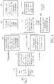
- FIG. 2is a schematic diagram of a method of unlocking a screen based on fingerprint recognition according to an embodiment of the present invention.
- FIG. 3is a schematic diagram of a fingerprint sensing system according to an embodiment of the present invention.
- FIG. 4is a flowchart of a screen unlocking process according to an embodiment of the present invention.
- FIG. 5is a schematic diagram of information associated with the position of the touch finger for the display driver circuit and the fingerprint sensing circuit.
- FIG. 6is a schematic diagram of a fingerprint sensing system with backlight control according to an embodiment of the present invention.
- FIGS. 7 - 9are timing diagrams of the operations of the fingerprint sensing system.
- FIG. 10 Ais a schematic diagram of a fingerprint sensing system according to an embodiment of the present invention.
- FIG. 10 Bis a schematic diagram of another fingerprint sensing system according to an embodiment of the present invention.
- the control circuit and related display panel of the present inventionare capable of the in-display fingerprint sensing function; that is, the fingerprint signals may be sensed at any position of the screen.
- a sensor arraydisposed in the display panel.
- the sensor arraymay be implemented as one or more sensing pixels, each having a photodiode for sensing the light to generate a sensing signal and a transistor for forwarding the sensing signal to the control circuit.
- an optical fingerprint unlocking operationmay be realized by using the photodiode(s) in the touch region to sense the light reflected from the touch finger.
- control circuit applied to deal with the touch sensing operation and fingerprint sensing operation of a display device having touch and fingerprint sensing functionsmay be a fingerprint, touch and display integration (FTDI) circuit.
- FTDIfingerprint, touch and display integration
- the FTDI circuitmay be implemented as an integrated circuit integrated in a single chip.
- the FTDI circuitmay be a combination of multiple chips having control circuits with different functions.
- the control circuitwill generally be called “FTDI circuit” hereinafter.
- FIG. 2is a schematic diagram of a method of unlocking a screen based on fingerprint recognition according to an embodiment of the present invention.
- the usermay touch any position of the screen with a finger.
- the optical fingerprint unlocking schemerequires that the panel emits light at the touch region so as to sense the reflected light from the finger. Therefore, if the finger touch is detected, the touch sensing circuit of the FTDI circuit may wake up the display driver circuit of the FTDI circuit, in order to show a specific image on the screen. Without control of the system processor, the display driver circuit may light on the screen to show the image by using an internal clock display scheme.
- the internal clock displaymeans that the display data may be outputted to the panel from the FTDI circuit based on control and synchronization of an internal clock of the FTDI circuit. In such a situation, no additional clock from the system processor is required, and the image may be shown without the control of the system processor. This reduces the back and forth communication between the FTDI circuit and the system processor, so as to reduce the required time consumption for fingerprint recognition.
- the display driver circuitmay control the panel to show an exposure icon at the finger touch position. Meanwhile, no exposure is required in other areas on the panel (i.e., the areas except for the finger touch position), and thus the black image may be shown in order to save power consumption, as shown in FIG. 2 .
- the fingerprint sensing circuitmay start to perform fingerprint sensing on the touch region and receive the fingerprint image signals.
- the related image dataare then forwarded to the system processor, and the system processor may perform matching and determine whether the received fingerprint image have a predetermined feature in the database.
- the screenmay be unlocked and show the wallpaper if the fingerprint matching is successful.
- the system processormay include a security module such as a trust zone, where the fingerprint matching may be performed to determine whether to unlock the screen. In the trust zone, the information of fingerprint features of the registered fingerprint may be recorded. An algorithm is applied to determine whether the received fingerprint image matches with the recorded fingerprint features, so as to determine whether to unlock the screen.
- the userin order to unlock the screen, the user only needs to put his/her finger on an arbitrary position of the screen, and the fingerprint sensing operation may be performed on the touch position. This achieves the blind unlocking from the off-screen mode, and also simplifies the fingerprint sensing flow to increase the sensing speed, so as to improve the user experience of fingerprint recognition.
- FIG. 3is a schematic diagram of a fingerprint sensing system 30 according to an embodiment of the present invention.
- the fingerprint sensing system 30includes a system processor 300 , an FTDI circuit 302 , and a display panel 304 .
- the system processor 300may be a core processor of the electronic system, such as a central processing unit (CPU), a microcontroller unit (MCU), a microprocessor, and the like.
- the system processor 300may be an MCU for controlling various applications and operations.
- the system processor 300may include a security module such as a trust zone, where an algorithm is configured to perform fingerprint matching.
- the FTDI circuit 302aims at capturing or extracting the fingerprint image from the display panel 304 , and processing the received fingerprint signals to amplify and acquire the desired image data.
- the FTDI circuit 302may be served as a control circuit for controlling the operations of the display panel 304 .
- the display panel 304may be an in-cell touch and fingerprint panel, where the touch sensor and fingerprint sensor and their related wire connection circuits are disposed inside the display panel 304 , e.g., disposed on the substrate of the display panel 304 .
- the FTDI circuit 302includes a display driver circuit 312 , a touch sensing circuit 314 and a fingerprint sensing circuit 316 .
- the display driver circuit 312is configured to control the display panel 304 to emit light and show the corresponding exposure icon.
- the touch sensing circuit 314is configured to detect a finger touch on the display panel 304 and determine the position of the display panel 304 where the finger touch is detected.
- the fingerprint sensing circuit 316is configured to perform fingerprint sensing on any position(s) of the display panel 304 and receive the fingerprint image signals correspondingly.
- the display driver circuit 312may communicate with the system processor 300 through a mobile industry processor interface (MIPI). During the normal display process, the display driver circuit 312 may receive image data from the system processor 300 , and output the voltage signals of image data to the display panel 304 .
- the display driver circuit 312may include source and gate drivers for outputting the voltage signals and related control signals to the display circuits of the display panel 304 , in order to realize the display control.
- the display driver circuit 312is also capable of the internal clock display function, where the display driver circuit 312 may generate the image signals without control of the system processor 300 , and the image signals may be sent to the display panel 304 based on control and synchronization of the internal clock of the FTDI circuit 302 .
- the touch sensing circuit 314may realize the touch sensing functions, to detect the finger touch on the display panel 304 .
- the touch sensing circuit 314may include a touch MCU for controlling the touch sensing operations.
- the touch MCUmay communicate with the system processor 300 through a serial peripheral interface (SPI) or an inter-integrated circuit (I2C) interface.
- the touch sensing circuit 314may also include a touch analog front-end (AFE) circuit, which is configured to output touch driving signals to the display panel 304 and correspondingly receive touch sensing signals from the touch sensor of the display panel 304 .
- AFEtouch analog front-end
- the touch sensing circuit 314may determine that a finger touch appears on a specific position or zone of the display panel 304 , and thereby notify the display driver circuit 312 to show the exposure icon at the position or zone and notify the fingerprint sensing circuit 316 to perform fingerprint sensing on the position or zone.
- the display driver circuit 312may control the display panel 304 to show the exposure icon, to indicate the position of the touch finger.
- the fingerprint sensing circuit 316is configured to perform the fingerprint sensing functions, to scan the fingerprint sensor and receive the fingerprint image signals from the display panel 304 .
- the fingerprint sensing circuit 316may include a gate control circuit for transmitting control signals to the fingerprint sensor to perform scanning, and include a fingerprint AFE circuit for receiving the fingerprint image signals correspondingly.
- the fingerprint sensing circuit 316may also include a fingerprint readout circuit, which is capable of amplifying the peak and valley information in the received fingerprint image signals and filtering out unwanted noises and interferences.
- the fingerprint readout circuitmay communicate with the system processor 300 through an SPI.
- the peak and valley information in the fingerprint imagemay be sent to the system processor 300 , allowing the system processor 300 to perform fingerprint matching and recognition in a security module, e.g., the trust zone.
- the fingerprint sensing circuit 316is capable of selectively scanning specific zone(s) of the display panel 304 to receive the fingerprint image signals, where the zone (s) may correspond to the position where finger touch is detected.
- the touch sensing circuit 314may be coupled to the display driver circuit 312 and the fingerprint sensing circuit 316 , and communication is perform therebetween.
- the display driver circuit 312may send a synchronization signal or an internal clock to the touch sensing circuit 314 and the fingerprint sensing circuit 316 , to synchronize the display control, touch sensing and fingerprint sensing operations.
- An internal interfaceis also disposed between the touch sensing circuit 314 and each of the display driver circuit 312 and the fingerprint sensing circuit 316 , allowing the touch sensing circuit 314 to send the information of finger touch position to the display driver circuit 312 and the fingerprint sensing circuit 316 , to realize the in-display fingerprint sensing.
- the touch sensing circuit 314may perform touch sensing to calculate the coordinate point of the touch position.
- the touch sensing circuit 314then informs the display driver circuit 312 and the fingerprint sensing circuit 316 of the coordinate information; hence, the display driver circuit 312 may control the display panel 304 to show the exposure icon at the coordinate point, and the fingerprint sensing circuit 316 may scan the zone (s) corresponding to the coordinate point to receive the fingerprint image.
- FIG. 4is a flowchart of a screen unlocking process 40 according to an embodiment of the present invention.
- the screen unlocking process 40which may be implemented in a control circuit for a panel such as the FTDI circuit 302 shown in FIG. 3 , includes the following steps:
- Step 400Start.
- Step 402The touch sensing circuit 314 determines a finger touch.
- Step 404The touch sensing circuit 314 sends information of finger position to the display driver circuit 312 and the fingerprint sensing circuit 316 .
- Step 406The display driver circuit 312 is woken up and controls the display panel 304 to show the exposure icon and perform light emission.
- Step 408The fingerprint sensing circuit 316 is woken up and selects zone(s) to perform fingerprint sensing.
- Step 410The display driver circuit 312 enters a standby mode after the fingerprint sensing is complete.
- Step 412The fingerprint sensing circuit 316 sends the fingerprint image data to the system processor 300 .
- Step 414The fingerprint sensing circuit 316 enters a standby mode after the fingerprint sensing is complete and the fingerprint image data is sent.
- Step 416The system processor 300 performs fingerprint matching.
- Step 418The display driver circuit 312 receives an indication from the system processor 300 to start a normal display operation if the system processor 300 determines that the fingerprint matching is successful.
- the display panel 304is in the off-screen mode, and the display driver circuit 312 and the fingerprint sensing circuit 316 are in the sleep mode or standby mode.
- the detectionmay be performed by the touch sensing circuit 314 only.
- low power wakeup gesture detectionmay be performed, in order to save power consumption.
- the touch sensing circuit 314may be periodically woken up to output a scan pulse to detect the existence of touch finger, while other modules and circuits in the FTDI circuit 302 are in the sleep mode.
- the touch sensing circuit 314may perform 1-dimensional (1D) scan to detect whether there is a finger putting on the screen.
- the 1D scanrefers to scan for detecting a touch event without obtaining the detailed information such as coordinate point of the finger.
- the periodic 1D scanmay achieve lower power consumption since it simply detects the existence of finger touch without making any efforts to calculate the detailed information of the finger touch.
- the touch sensing circuit 314may start to perform 2-dimensional (2D) scan to obtain the touch coordinate point of the finger.
- 2-dimensional (2D) scanto obtain the touch coordinate point of the finger.
- the capacitance value of several sensing electrodes closer to the touch areamay be acquired to calculate the extent of touch area and the coordinate point of the touch finger. If the extent of touch area is greater than a predetermined threshold, the touch event may be determined to be a valid finger touch, and thus the display driver circuit 312 and the fingerprint sensing circuit 316 may be woken up from the sleep mode to perform the follow-up steps.
- the touch sensing circuit 314may send the information associated with the position of touch finger to the display driver circuit 312 and the fingerprint sensing circuit 316 .
- FIG. 5is a schematic diagram of information associated with the position of touch finger for the display driver circuit 312 and the fingerprint sensing circuit 316 .
- the touch sensing circuit 314may send the information of touch position to the display driver circuit 312 , allowing the display driver circuit 312 to control the display panel 304 to emit light and correspondingly show the exposure icon at the position where the finger touch is detected.
- the display driver circuit 312may start the internal clock display, where the display operation is controlled by using the internal clock of the FTDI circuit 302 without additional control of the system processor 300 . Meanwhile, the display driver circuit 312 may send the synchronization signal to the touch sensing circuit 314 and the fingerprint sensing circuit 316 to synchronize the display control, touch sensing and fingerprint sensing operations of the FTDI circuit 302 .
- a backlight controllermay be included to perform backlight control.
- the display panel 304may be an LCD panel having a backlight unit 610 , where the display operation is performed by turning on the backlight unit 610 .
- the display driver circuit 312may further include a backlight controller 620 , which is configured to control the backlight unit 610 to emit light and also control the emitted light intensity. Note that in a conventional LCD panel, the display operations are controlled by the system processor, and thus the related backlight unit is also controlled by the system processor.
- the backlight unit 610may also be controlled by the backlight controller 620 of the FTDI circuit 302 , and thus the display operations may be realized without the control of the system processor 300 .
- the information associated with touch positionshould also be sent to the fingerprint sensing circuit 316 to facilitate the fingerprint sensing operations.
- the fingerprint sensor on the display panel 304may be separated into several zones, and the fingerprint scan may be performed in one or several zones based on the touch position of the finger, as shown in FIG. 5 .
- the touch sensing circuit 314may determine the position and corresponding zone (s) of the display panel 304 on which the finger touch is detected, and send the related information to the fingerprint sensing circuit 316 ; hence, the fingerprint sensing circuit 316 may perform fingerprint sensing on the zone (s) and receive the fingerprint image signals from the zone (s) correspondingly. In such a situation, the fingerprint sensing may not need to be performed on the entire screen.
- the fingerprint sensingis performed only on the zone (s) corresponding to the position on which the finger touch is detected, and the fingerprint image signals are only received from the zone(s) determined or selected based on the finger's position. This reduces the time consumption and computation resources for fingerprint recognition and matching, and thus the fingerprint recognition speed may be improved.
- the fingerprint sensing circuit 316may notify the display driver circuit 312 to enter the standby mode, to wait for follow-up instructions. Therefore, the display driver circuit 312 may control the display panel 304 to stop emitting light, e.g., to disable the backlight unit 610 , and the screen becomes off.
- the fingerprint sensing circuit 316may also send an interrupt signal to the system processor 300 to notify that the system processor 300 may start to perform fingerprint matching, and then output the image data corresponding to the received fingerprint image signals to the system processor 300 .
- an interrupt pinis connected between the system processor 300 and the FTDI circuit 302 , and the interrupt signal may be sent via the interrupt pin.
- the interrupt signalmay be included in a packet transmitted through the SPI interface disposed between the system processor 300 and the fingerprint sensing circuit 316 .
- the system processor 300may perform fingerprint matching to determine whether to unlock the display panel 304 .
- the system processor 300may include a trust zone configured to perform fingerprint matching. If the matching is successful (e.g., the matching indicates that the received fingerprint image has a specific feature), the system processor 300 may unlock the display panel 304 and control the display panel 304 and the display driver circuit 312 to start the normal display operations. As a result, the system processor 300 may start to deal with the fingerprint recognition functions after the interrupt signal is received. Before the fingerprint sensing operation is complete, the system processor 300 may not be involved in the screen unlocking operation, and thus tedious communications between the system processor and the FTDI circuit in the conventional unlocking method may be omitted.
- FIG. 7is a timing diagram of the operations of the fingerprint sensing system 30 or 60 , where the statuses of each circuit module of the FTDI circuit 302 and the interfaces between the FTDI circuit 302 and the system processor 300 are illustrated.
- both the display driver circuit 312 and the fingerprint sensing circuit 316are in the sleep mode, and the display panel 304 is off-screen under the turned-off backlight.
- the touch sensing circuit 314is operated to detect the finger touch.
- the touch sensing circuit 314detects a finger touch and wakes up the display driver circuit 312 and the fingerprint sensing circuit 316 , and the operations of fingerprint sensing starts.
- the fingerprint sensing circuit 316may perform fingerprint (FPR) sensing by itself, i.e., without control of the system processor 300 ; and the display driver circuit 312 may perform the internal clock display, i.e., without control of the system processor 300 , where the backlight unit 610 may be turned on by the display driver circuit 312 . At this moment, the display panel 304 may show the exposure icon at the touch position of finger with a black screen at other areas. Note that before the fingerprint sensing operation is complete, no communication between the system processor 300 and the FTDI circuit 302 is required.
- FPRfingerprint sensing
- the fingerprint sensing circuit 316sends an interrupt signal to the system processor (AP) 300 , and then correspondingly sends the fingerprint image data through the fingerprint control interface (e.g., the SPI interface).
- the system processor 300may start to perform fingerprint recognition and matching. Subsequently, after the fingerprint matching is successful, the normal display operations may be started, and the touch sensing operations may be performed normally. At this moment, the system processor 300 may continuously send display data stream to the display driver circuit 312 through the display control interface (e.g., the MIPI interface), and the touch sensing circuit 314 may continuously report touch information to the system processor 300 through the touch control interface (e.g., the I2C interface).
- the display driver circuit 312e.g., the MIPI interface
- the touch sensing circuit 314may continuously report touch information to the system processor 300 through the touch control interface (e.g., the I2C interface).
- the fingerprint recognitionmay not be performed successfully and/or the fingerprint matching may indicate a wrong matching result.
- the system processor 300may notify the FTDI circuit 302 that the fingerprint matching is failed, or the FTDI circuit 302 may wait for a period of time but no confirmation message from the system processor 300 is received; hence, the FTDI circuit 302 may control the display panel 304 to enter the off-screen mode, and the backlight emission may be disabled, as shown in FIG. 8 .
- each circuit and module of the FTDI circuit 302may return to original statuses; that is, the display driver circuit 312 and the fingerprint sensing circuit 316 return to the sleep mode, and the touch sensing circuit 314 restarts to perform the low power wakeup gesture detection with 1D scan, to detect the finger touch.
- the touch sensing circuit 314is still operating to detect the finger touch during the fingerprint recognition process for screen unlocking.
- the fingerprint sensing operationmay be interrupted, as shown in FIG. 9 .
- the fingerprint sensing circuit 316may stop the fingerprint sensing operation and enter the sleep mode.
- the display driver circuit 312may stop displaying the exposure icon and enter the sleep mode, and meanwhile the backlight is disabled and the display panel 304 becomes off-screen.
- the touch sensing circuit 314restarts to perform the low power wakeup gesture detection with 1D scan, to detect the finger touch. This touch detection during the screen unlocking process may prevent unnecessary fingerprint sensing operation after the finger is removed.
- the present inventionaims at providing a screen unlocking method based on fingerprint recognition fora display panel and an FTDI circuit.
- the display driver circuitmay control the panel to show an exposure icon at the finger touch position, to generate light emission for optical fingerprint sensing, as shown in FIG. 5 .
- the exposure iconmay not be limited to that illustrated in this disclosure.
- the exposure iconmay be of any shape such as a circle or a square, and/or the exposure icon may be shown with any feasible color or combination of several colors, as long as the exposure icon and the corresponding light emission may cover the fingerprint sensing area.
- the displayed coloris associated with the wavelength of emitted light, and the wavelength may influence the sensing result of the fingerprint image.
- the same display datamay generate different colors on different panels; hence, it is preferable to apply a flexible exposure icon, where the appearance such as color, size, and/or shape of the exposure icon may be configurable or programmable by a user.
- the display panelmay also show several customized messages such as time, date, and/or weather when the exposure icon is shown.
- the FTDI circuitis configured to control an LCD panel and thus a backlight controller may be applied.
- the FTDI circuitmay be configured to control an organic light-emitting diode (OLED) panel; hence, the light emission for fingerprint sensing may be controlled by driving OLEDs in the display pixels, and the circuit structure of the FTDI circuit 302 shown in FIG. 3 without the backlight controller may be feasible.
- OLEDorganic light-emitting diode
- the screen unlocking method of the present inventionis applicable to any type of display panel, which should not be a limitation on the scope of the present invention.
- fingerprint sensingmay be performed without control and command of the system processor, where the fingerprint sensing scheme may not be limited to optical fingerprint sensing as illustrated in this disclosure. Other type of fingerprint sensing such as ultrasonic fingerprint sensing may also be feasible.
- FIG. 10 Ais a schematic diagram of a fingerprint sensing system 100 according to an embodiment of the present invention.
- the fingerprint sensing system 100includes a system processor (AP) 1000 , an FTDI circuit 1002 , and a display panel 1004 , where the FTDI circuit 1002 may be a single chip integrated with the processing circuits for display, touch and fingerprint.
- the related operations and interface controls of the FTDI circuit 1002are similar to those of the FTDI circuit 302 shown in FIG. 3 , and will not be narrated herein.
- the single-chip FTDI circuitmay be replaced by a multiple-chip implementation.
- FIG. 10 Bis a schematic diagram of another fingerprint sensing system 150 according to an embodiment of the present invention.
- the fingerprint sensing system 150is different from the fingerprint sensing system 100 in that, the fingerprint sensing system 150 includes a touch and display driving integration (TDDI) circuit 1502 and a fingerprint readout integrated circuit (FPR ROIC) 1503 , which replace the functions of the FTDI circuit 1002 in the fingerprint sensing system 100 .
- TDDItouch and display driving integration
- FPR ROICfingerprint readout integrated circuit
- An interfaceis disposed between the TDDI circuit 1502 and the FPR ROIC 1503 , for forwarding necessary messages such as the synchronization signal for synchronizing the display driving, touch sensing and fingerprint sensing functions and the information related to finger touch position and related fingerprint sensing zone(s).
- the present inventionprovides a control circuit for controlling the display panel to unlock the screen based on fingerprint recognition.
- the control circuitmay be an FTDI circuit implemented as a single chip, or a two-chip structure with combination of a TDDI circuit and a fingerprint ROIC.
- the fingerprint sensing circuit and the display driver circuitmay be in the sleep mode when the screen is off, and only the touch sensing circuit is operating to detect a finger touch.
- the fingerprint sensing circuit and the display driver circuitare woken up only when the finger touch is detected. Therefore, the display driver circuit may control the panel to emit light and show an exposure icon correspondingly by using an internal clock display scheme without control of the system processor, and the fingerprint sensing circuit may perform fingerprint sensing on the touch zone (s).
- the FTDI circuitmay notify the system processor after the fingerprint sensing is complete, allowing the system processor to perform fingerprint recognition and matching.
- the screenis unlocked if the fingerprint matching is successful.
- the screen unlocking method of the present inventioncan increase the speed of fingerprint recognition, so as to achieve better user experience of screen unlocking.
Landscapes
- Engineering & Computer Science (AREA)
- Theoretical Computer Science (AREA)
- General Engineering & Computer Science (AREA)
- Physics & Mathematics (AREA)
- General Physics & Mathematics (AREA)
- Human Computer Interaction (AREA)
- Multimedia (AREA)
- Computer Hardware Design (AREA)
- Social Psychology (AREA)
- Psychiatry (AREA)
- General Health & Medical Sciences (AREA)
- Computer Vision & Pattern Recognition (AREA)
- Health & Medical Sciences (AREA)
- User Interface Of Digital Computer (AREA)
- Image Input (AREA)
- Collating Specific Patterns (AREA)
- Illuminated Signs And Luminous Advertising (AREA)
- Telephone Function (AREA)
Abstract
Description
Claims (12)
Priority Applications (7)
| Application Number | Priority Date | Filing Date | Title |
|---|---|---|---|
| US16/851,043US11551466B2 (en) | 2019-08-21 | 2020-04-16 | Control circuit and related method for controlling display panel |
| TW109121308ATWI770539B (en) | 2019-08-21 | 2020-06-23 | Control circuit and related method for controlling display panel |
| TW111120855ATWI789312B (en) | 2019-08-21 | 2020-06-23 | Control circuit and related method for controlling display panel |
| CN202010717624.0ACN112416158B (en) | 2019-08-21 | 2020-07-23 | Control circuit and method for controlling display screen |
| US16/999,019US11232282B2 (en) | 2019-08-21 | 2020-08-20 | Control circuit, display system, and related method of controlling display panel |
| TW109128638ATWI768441B (en) | 2019-08-21 | 2020-08-21 | Control circuit, display system, and related method of controlling display panel |
| CN202010851308.2ACN112416161B (en) | 2019-08-21 | 2020-08-21 | Control circuit and display system and method for controlling display screen |
Applications Claiming Priority (2)
| Application Number | Priority Date | Filing Date | Title |
|---|---|---|---|
| US201962890052P | 2019-08-21 | 2019-08-21 | |
| US16/851,043US11551466B2 (en) | 2019-08-21 | 2020-04-16 | Control circuit and related method for controlling display panel |
Related Parent Applications (1)
| Application Number | Title | Priority Date | Filing Date |
|---|---|---|---|
| US16/921,921Continuation-In-PartUS11270095B2 (en) | 2019-08-21 | 2020-07-06 | Electronic circuit having display driving function, touch sensing function and fingerprint sensing function |
Related Child Applications (2)
| Application Number | Title | Priority Date | Filing Date |
|---|---|---|---|
| US16/921,921Continuation-In-PartUS11270095B2 (en) | 2019-08-21 | 2020-07-06 | Electronic circuit having display driving function, touch sensing function and fingerprint sensing function |
| US16/999,019Continuation-In-PartUS11232282B2 (en) | 2019-08-21 | 2020-08-20 | Control circuit, display system, and related method of controlling display panel |
Publications (2)
| Publication Number | Publication Date |
|---|---|
| US20210056333A1 US20210056333A1 (en) | 2021-02-25 |
| US11551466B2true US11551466B2 (en) | 2023-01-10 |
Family
ID=74645823
Family Applications (2)
| Application Number | Title | Priority Date | Filing Date |
|---|---|---|---|
| US16/851,043Active2040-04-30US11551466B2 (en) | 2019-08-21 | 2020-04-16 | Control circuit and related method for controlling display panel |
| US16/865,404ActiveUS11170194B2 (en) | 2019-08-21 | 2020-05-03 | Control circuit and related method for controlling display panel |
Family Applications After (1)
| Application Number | Title | Priority Date | Filing Date |
|---|---|---|---|
| US16/865,404ActiveUS11170194B2 (en) | 2019-08-21 | 2020-05-03 | Control circuit and related method for controlling display panel |
Country Status (3)
| Country | Link |
|---|---|
| US (2) | US11551466B2 (en) |
| CN (2) | CN112416157B (en) |
| TW (3) | TWI770539B (en) |
Families Citing this family (20)
| Publication number | Priority date | Publication date | Assignee | Title |
|---|---|---|---|---|
| KR102726419B1 (en)* | 2019-08-29 | 2024-11-06 | 삼성디스플레이 주식회사 | Display device and driving method thereof |
| US11403983B2 (en)* | 2019-09-02 | 2022-08-02 | Samsung Electronics Co., Ltd. | Display controller, display system including the display controller, and method of operating the display controller |
| US11380128B2 (en)* | 2020-03-02 | 2022-07-05 | Himax Technologies Limited | Apparatus integrated with fingerprint recognition and touch detection, and method of controlling the same |
| US11762202B1 (en)* | 2020-03-31 | 2023-09-19 | Snap Inc. | Ring-mounted flexible circuit remote control |
| TWI794749B (en)* | 2020-05-03 | 2023-03-01 | 神盾股份有限公司 | Fingerprint sensing device and operation method thereof |
| US11379080B2 (en)* | 2020-06-05 | 2022-07-05 | International Business Machines Corporation | Automatically correcting touchscreen errors |
| US11556195B2 (en)* | 2020-06-25 | 2023-01-17 | Synaptics Incorporated | Input-display device with shared memory |
| TWM615933U (en)* | 2020-07-21 | 2021-08-21 | 神亞科技股份有限公司 | Fingerprint sensing device |
| KR20220132245A (en)* | 2021-03-23 | 2022-09-30 | 삼성전자주식회사 | Electronic device and its fingerprint recognition method |
| CN115249367A (en)* | 2021-04-28 | 2022-10-28 | 广州印芯半导体技术有限公司 | Image sensing device and fingerprint sensing method |
| US11670108B2 (en)* | 2021-04-28 | 2023-06-06 | Guangzhou Tyrafos Semiconductor Technologies Co., Ltd | Image sensing device and fingerprint sensing method |
| TWI782568B (en)* | 2021-06-09 | 2022-11-01 | 大陸商北京集創北方科技股份有限公司 | Capacitive fingerprint sensing device and information processing device using the same |
| CN113778273B (en)* | 2021-07-29 | 2022-12-23 | 荣耀终端有限公司 | Light spot display method, electronic device, and computer-readable storage medium |
| CN115620346B (en)* | 2021-09-30 | 2023-09-19 | 荣耀终端有限公司 | Under-screen fingerprint acquisition method and electronic equipment |
| US11861095B2 (en)* | 2021-10-20 | 2024-01-02 | Dish Network Technologies India Private Limited | Touchscreen lock feature for playback of media content |
| CN114581964B (en)* | 2022-02-22 | 2025-07-04 | 业泓科技(成都)有限公司 | Under-screen fingerprint recognition circuit and its stacked structure, display panel and fingerprint capture method |
| TWI822154B (en)* | 2022-06-29 | 2023-11-11 | 華碩電腦股份有限公司 | Electronic device |
| US12314514B2 (en)* | 2022-10-28 | 2025-05-27 | Himax Technologies Limited | Touch sensing apparatus, electronic device and touch operation recording method thereof |
| TWI823743B (en)* | 2023-01-06 | 2023-11-21 | 大陸商北京集創北方科技股份有限公司 | Touch driving method, TDDI chip and information processing device |
| TWI861680B (en)* | 2023-01-12 | 2024-11-11 | 友達光電股份有限公司 | Touch display device |
Citations (49)
| Publication number | Priority date | Publication date | Assignee | Title |
|---|---|---|---|---|
| TW201145107A (en) | 2010-06-11 | 2011-12-16 | Hon Hai Prec Ind Co Ltd | Electronic device with touch input unit and touch input method thereof |
| US20130021289A1 (en) | 2011-07-19 | 2013-01-24 | Wei Chen | Touch sensitive displays |
| US20140101737A1 (en) | 2012-06-11 | 2014-04-10 | Samsung Electronics Co., Ltd. | Mobile device and control method thereof |
| US20150109237A1 (en) | 2013-10-23 | 2015-04-23 | Wistron Corp. | Input apparatus, input mode switching method and computer apparatus |
| US20150135108A1 (en) | 2012-05-18 | 2015-05-14 | Apple Inc. | Device, method, and graphical user interface for manipulating user interfaces based on fingerprint sensor inputs |
| CN104798311A (en) | 2013-10-18 | 2015-07-22 | Lg电子株式会社 | Mobile terminal and control method thereof |
| CN104850292A (en) | 2015-06-01 | 2015-08-19 | 京东方科技集团股份有限公司 | Embedded touch screen, driving method of embedded touch screen and display device |
| TWM509927U (en) | 2014-07-23 | 2015-10-01 | Focaltech Electronics Ltd | Fingerprint sensing function device |
| US20150286268A1 (en) | 2014-04-07 | 2015-10-08 | Japan Display Inc. | Display device equipped with input sensor and control method of display device |
| TW201604792A (en) | 2014-07-23 | 2016-02-01 | 敦泰電子有限公司 | Fingerprint sensing device |
| TW201604705A (en) | 2014-07-23 | 2016-02-01 | 敦泰電子有限公司 | Electronic device for fingerprint sensing and method for invoking applications thereof |
| US20160110056A1 (en) | 2014-10-15 | 2016-04-21 | Samsung Electronics Co., Ltd. | Method and apparatus for providing user interface |
| US20160202779A1 (en) | 2015-01-13 | 2016-07-14 | Xiaomi Inc. | Apparatus for implementing touch control and fingerprint identification and terminal device comprising such apparatus |
| US20160253540A1 (en) | 2014-06-18 | 2016-09-01 | Boe Technology Group Co., Ltd. | Personal mobile terminal device with fingerprint identification function |
| TWI559233B (en) | 2015-08-17 | 2016-11-21 | 速博思股份有限公司 | Two-substrate fingerprint recognition device |
| CN106203026A (en) | 2016-06-23 | 2016-12-07 | 华勤通讯技术有限公司 | Fingerprint Identification sensor, display screen, electronic equipment and function activating method |
| US20160371691A1 (en) | 2015-06-22 | 2016-12-22 | Samsung Electronics Co., Ltd. | Portable apparatus and method for changing screen of the same |
| TW201704969A (en) | 2015-07-20 | 2017-02-01 | Lg顯示器股份有限公司 | Fingerprint sensor integrated type touch screen device |
| US20170124372A1 (en) | 2015-10-30 | 2017-05-04 | Essential Products, Inc. | Fingerprint sensors for mobile devices |
| US20170200037A1 (en) | 2016-01-11 | 2017-07-13 | Samsung Display Co., Ltd. | Display device and driving method thereof |
| US20170206395A1 (en) | 2016-01-20 | 2017-07-20 | Au Optronics Corporation | Fingerprint identification device |
| US9720639B1 (en) | 2016-09-02 | 2017-08-01 | Brent Foster Morgan | Systems and methods for a supplemental display screen |
| US9733740B2 (en)* | 2014-06-23 | 2017-08-15 | Samsung Electronics Co., Ltd. | Method of processing fingerprint and electronic device thereof |
| CN107402663A (en) | 2016-04-27 | 2017-11-28 | 三星电子株式会社 | Fingerprint authentication method and the electronic equipment for performing this method |
| US20170344148A1 (en) | 2016-05-30 | 2017-11-30 | Lg Display Co., Ltd. | Display device including sensor screen |
| US20170351850A1 (en) | 2016-06-01 | 2017-12-07 | Samsung Electronics Co., Ltd. | Method for activating function using fingerprint and electronic device including touch display supporting the same |
| US20180035923A1 (en) | 2016-08-05 | 2018-02-08 | Samsung Electronics Co., Ltd. | Electronic device including fingerprint sensor |
| US20180101715A1 (en) | 2016-10-11 | 2018-04-12 | Samsung Electronics Co., Ltd. | Electronic device having plurality of fingerprint sensing modes and method for controlling the same |
| US20180164943A1 (en) | 2016-12-13 | 2018-06-14 | Novatek Microelectronics Corp. | Touch apparatus and touch detection integrated circuit thereof |
| TWI630523B (en) | 2017-08-15 | 2018-07-21 | 奇景光電股份有限公司 | Touch apparatus and sensing method and touch sensing circuit thereof |
| US20180218195A1 (en) | 2016-01-29 | 2018-08-02 | Synaptics Incorporated | Biometric imaging with hover detection |
| US20180224999A1 (en) | 2017-02-03 | 2018-08-09 | Samsung Electronics Co., Ltd. | Apparatus and method for controlling fingerprint sensor |
| US20180260600A1 (en) | 2014-11-17 | 2018-09-13 | Cypress Semiconductor Corporation | Capacitive Fingerprint Sensor with Quadrature Demodulator and Multiphase Scanning |
| TW201839650A (en) | 2017-04-28 | 2018-11-01 | 大陸商Oppo廣東移動通信有限公司 | Unlocking control method and mobile terminal |
| TW201839659A (en) | 2017-04-28 | 2018-11-01 | 大陸商廣東歐珀移動通信有限公司 | Method for displaying fingerprint identification area and mobile terminal |
| EP3401772A1 (en) | 2017-05-12 | 2018-11-14 | Samsung Electronics Co., Ltd. | Electronic device including a plurality of input devices and control method thereof |
| TW201842467A (en) | 2017-12-29 | 2018-12-01 | 大陸商昆山國顯光電有限公司 | Fingerprint recognition control method, touch panel and touch display device capable of realizing full-screen in-display fingerprint recognition |
| US20180349669A1 (en) | 2017-06-02 | 2018-12-06 | Samsung Electronics Co., Ltd. | Operating method of optical fingerprint sensor, operating method of electronic device including the optical fingerprint sensor, and display device including the optical fingerprint sensor |
| US20180348949A1 (en) | 2017-06-02 | 2018-12-06 | Samsung Electronics Co., Ltd. | Touch controller for driving touch screen including fingerprint sensing array, driving integrated circuit, and method of operating touch screen device including the same |
| US20180373361A1 (en) | 2017-06-22 | 2018-12-27 | Synaptics Incorporated | System and method for interference mitigation in a sensing device |
| US20190019048A1 (en) | 2016-12-26 | 2019-01-17 | Shenzhen GOODIX Technology Co., Ltd. | Method and device for guiding fingerprint recognition |
| US20190065808A1 (en)* | 2016-07-25 | 2019-02-28 | Vkansee (Beijing) Technology Co., Ltd. | Method and Apparatus for Controlling Fingerprint Acquisition Based on a Display Screen and Electronic Device |
| CN109409070A (en) | 2018-11-01 | 2019-03-01 | Oppo广东移动通信有限公司 | Application opening method, device, terminal and storage medium |
| TWI662452B (en) | 2018-03-23 | 2019-06-11 | 群邁通訊股份有限公司 | Portable electronic device and unlocking method |
| CN109885998A (en) | 2019-01-24 | 2019-06-14 | Oppo广东移动通信有限公司 | Fingerprint unlocking method and related equipment |
| CN110070006A (en) | 2019-04-01 | 2019-07-30 | Oppo广东移动通信有限公司 | Fingerprint identification method, electronic device and computer-readable medium |
| US20190354226A1 (en)* | 2017-01-31 | 2019-11-21 | Samsung Electronics Co., Ltd. | Electronic device and fingerprint recognition method of electronic device |
| US20200092411A1 (en) | 2017-05-02 | 2020-03-19 | Huawei Technologies Co., Ltd. | Notification Processing Method and Electronic Device |
| US20200167537A1 (en)* | 2018-11-23 | 2020-05-28 | Lg Display Co., Ltd. | Complex Sensing Device, Display Device, and Sensing Method |
Family Cites Families (11)
| Publication number | Priority date | Publication date | Assignee | Title |
|---|---|---|---|---|
| CN105528099B (en)* | 2014-09-29 | 2018-04-13 | 神盾股份有限公司 | Electronic device combining fingerprint identification function with touch screen and control method thereof |
| CN107766777A (en)* | 2016-08-18 | 2018-03-06 | 北京小米移动软件有限公司 | Fingerprint recognition component, pressure detection method and fingerprint recognition IC |
| CN106484483B (en)* | 2016-10-18 | 2020-01-31 | 维沃移动通信有限公司 | Application program interface display method and mobile terminal |
| WO2018137165A1 (en)* | 2017-01-24 | 2018-08-02 | 深圳市汇顶科技股份有限公司 | Electronic device |
| CN107122760B (en)* | 2017-05-16 | 2019-10-18 | Oppo广东移动通信有限公司 | Fingerprint identification method and related products |
| CN107728979A (en)* | 2017-09-30 | 2018-02-23 | 联想(北京)有限公司 | A kind of processing method and electronic equipment |
| WO2019100368A1 (en)* | 2017-11-27 | 2019-05-31 | 深圳市汇顶科技股份有限公司 | Launching method and display method for application program, and terminal |
| CN108763909A (en)* | 2018-06-05 | 2018-11-06 | 北京小米移动软件有限公司 | Touch-responsive method and device |
| CN109753947B (en)* | 2019-01-24 | 2021-04-13 | Oppo广东移动通信有限公司 | Fingerprint unlocking method and related equipment |
| CN109992154B (en)* | 2019-03-14 | 2022-10-21 | 南京观海微电子有限公司 | Touch screen with full screen fingerprint identification function and fingerprint identification method |
| CN110135276A (en)* | 2019-04-22 | 2019-08-16 | 福建华佳彩有限公司 | It is a kind of to shield lower fingerprint identification method and device comprehensively |
- 2020
- 2020-04-16USUS16/851,043patent/US11551466B2/enactiveActive
- 2020-05-03USUS16/865,404patent/US11170194B2/enactiveActive
- 2020-06-23TWTW109121308Apatent/TWI770539B/enactive
- 2020-06-23TWTW111120855Apatent/TWI789312B/enactive
- 2020-07-14TWTW109123740Apatent/TWI784293B/enactive
- 2020-07-23CNCN202010717531.8Apatent/CN112416157B/enactiveActive
- 2020-07-23CNCN202010717624.0Apatent/CN112416158B/enactiveActive
Patent Citations (54)
| Publication number | Priority date | Publication date | Assignee | Title |
|---|---|---|---|---|
| TW201145107A (en) | 2010-06-11 | 2011-12-16 | Hon Hai Prec Ind Co Ltd | Electronic device with touch input unit and touch input method thereof |
| US20130021289A1 (en) | 2011-07-19 | 2013-01-24 | Wei Chen | Touch sensitive displays |
| US20150135108A1 (en) | 2012-05-18 | 2015-05-14 | Apple Inc. | Device, method, and graphical user interface for manipulating user interfaces based on fingerprint sensor inputs |
| US20140101737A1 (en) | 2012-06-11 | 2014-04-10 | Samsung Electronics Co., Ltd. | Mobile device and control method thereof |
| CN104798311A (en) | 2013-10-18 | 2015-07-22 | Lg电子株式会社 | Mobile terminal and control method thereof |
| US20150109237A1 (en) | 2013-10-23 | 2015-04-23 | Wistron Corp. | Input apparatus, input mode switching method and computer apparatus |
| US20150286268A1 (en) | 2014-04-07 | 2015-10-08 | Japan Display Inc. | Display device equipped with input sensor and control method of display device |
| US20160253540A1 (en) | 2014-06-18 | 2016-09-01 | Boe Technology Group Co., Ltd. | Personal mobile terminal device with fingerprint identification function |
| US9733740B2 (en)* | 2014-06-23 | 2017-08-15 | Samsung Electronics Co., Ltd. | Method of processing fingerprint and electronic device thereof |
| TWM509927U (en) | 2014-07-23 | 2015-10-01 | Focaltech Electronics Ltd | Fingerprint sensing function device |
| TW201604792A (en) | 2014-07-23 | 2016-02-01 | 敦泰電子有限公司 | Fingerprint sensing device |
| TW201604705A (en) | 2014-07-23 | 2016-02-01 | 敦泰電子有限公司 | Electronic device for fingerprint sensing and method for invoking applications thereof |
| TWI610194B (en) | 2014-07-23 | 2018-01-01 | 敦泰電子有限公司 | Electronic device for fingerprint sensing and method for invoking applications thereof |
| US20160110056A1 (en) | 2014-10-15 | 2016-04-21 | Samsung Electronics Co., Ltd. | Method and apparatus for providing user interface |
| US20180260600A1 (en) | 2014-11-17 | 2018-09-13 | Cypress Semiconductor Corporation | Capacitive Fingerprint Sensor with Quadrature Demodulator and Multiphase Scanning |
| US20160202779A1 (en) | 2015-01-13 | 2016-07-14 | Xiaomi Inc. | Apparatus for implementing touch control and fingerprint identification and terminal device comprising such apparatus |
| CN104850292A (en) | 2015-06-01 | 2015-08-19 | 京东方科技集团股份有限公司 | Embedded touch screen, driving method of embedded touch screen and display device |
| CN104850292B (en) | 2015-06-01 | 2017-09-29 | 京东方科技集团股份有限公司 | A kind of In-cell touch panel, its driving method and display device |
| US20160371691A1 (en) | 2015-06-22 | 2016-12-22 | Samsung Electronics Co., Ltd. | Portable apparatus and method for changing screen of the same |
| TW201704969A (en) | 2015-07-20 | 2017-02-01 | Lg顯示器股份有限公司 | Fingerprint sensor integrated type touch screen device |
| TWI598789B (en) | 2015-07-20 | 2017-09-11 | Lg顯示器股份有限公司 | Fingerprint sensor integrated type touch screen device |
| TW201709106A (en) | 2015-08-17 | 2017-03-01 | 速博思股份有限公司 | Two-substrate fingerprint recognition device |
| TWI559233B (en) | 2015-08-17 | 2016-11-21 | 速博思股份有限公司 | Two-substrate fingerprint recognition device |
| US20170124372A1 (en) | 2015-10-30 | 2017-05-04 | Essential Products, Inc. | Fingerprint sensors for mobile devices |
| US20170200037A1 (en) | 2016-01-11 | 2017-07-13 | Samsung Display Co., Ltd. | Display device and driving method thereof |
| US20170206395A1 (en) | 2016-01-20 | 2017-07-20 | Au Optronics Corporation | Fingerprint identification device |
| US20180218195A1 (en) | 2016-01-29 | 2018-08-02 | Synaptics Incorporated | Biometric imaging with hover detection |
| CN107402663A (en) | 2016-04-27 | 2017-11-28 | 三星电子株式会社 | Fingerprint authentication method and the electronic equipment for performing this method |
| US20170344148A1 (en) | 2016-05-30 | 2017-11-30 | Lg Display Co., Ltd. | Display device including sensor screen |
| US20170351850A1 (en) | 2016-06-01 | 2017-12-07 | Samsung Electronics Co., Ltd. | Method for activating function using fingerprint and electronic device including touch display supporting the same |
| CN106203026A (en) | 2016-06-23 | 2016-12-07 | 华勤通讯技术有限公司 | Fingerprint Identification sensor, display screen, electronic equipment and function activating method |
| US20190065808A1 (en)* | 2016-07-25 | 2019-02-28 | Vkansee (Beijing) Technology Co., Ltd. | Method and Apparatus for Controlling Fingerprint Acquisition Based on a Display Screen and Electronic Device |
| US20180035923A1 (en) | 2016-08-05 | 2018-02-08 | Samsung Electronics Co., Ltd. | Electronic device including fingerprint sensor |
| US9720639B1 (en) | 2016-09-02 | 2017-08-01 | Brent Foster Morgan | Systems and methods for a supplemental display screen |
| US20180101715A1 (en) | 2016-10-11 | 2018-04-12 | Samsung Electronics Co., Ltd. | Electronic device having plurality of fingerprint sensing modes and method for controlling the same |
| US20180164943A1 (en) | 2016-12-13 | 2018-06-14 | Novatek Microelectronics Corp. | Touch apparatus and touch detection integrated circuit thereof |
| US20190019048A1 (en) | 2016-12-26 | 2019-01-17 | Shenzhen GOODIX Technology Co., Ltd. | Method and device for guiding fingerprint recognition |
| US20190354226A1 (en)* | 2017-01-31 | 2019-11-21 | Samsung Electronics Co., Ltd. | Electronic device and fingerprint recognition method of electronic device |
| US20180224999A1 (en) | 2017-02-03 | 2018-08-09 | Samsung Electronics Co., Ltd. | Apparatus and method for controlling fingerprint sensor |
| TW201839650A (en) | 2017-04-28 | 2018-11-01 | 大陸商Oppo廣東移動通信有限公司 | Unlocking control method and mobile terminal |
| TW201839659A (en) | 2017-04-28 | 2018-11-01 | 大陸商廣東歐珀移動通信有限公司 | Method for displaying fingerprint identification area and mobile terminal |
| US20200092411A1 (en) | 2017-05-02 | 2020-03-19 | Huawei Technologies Co., Ltd. | Notification Processing Method and Electronic Device |
| EP3401772A1 (en) | 2017-05-12 | 2018-11-14 | Samsung Electronics Co., Ltd. | Electronic device including a plurality of input devices and control method thereof |
| US20180329560A1 (en) | 2017-05-12 | 2018-11-15 | Samsung Electronics Co., Ltd. | Electronic device including a plurality of input devices and control method thereof |
| US20180349669A1 (en) | 2017-06-02 | 2018-12-06 | Samsung Electronics Co., Ltd. | Operating method of optical fingerprint sensor, operating method of electronic device including the optical fingerprint sensor, and display device including the optical fingerprint sensor |
| US20180348949A1 (en) | 2017-06-02 | 2018-12-06 | Samsung Electronics Co., Ltd. | Touch controller for driving touch screen including fingerprint sensing array, driving integrated circuit, and method of operating touch screen device including the same |
| US20180373361A1 (en) | 2017-06-22 | 2018-12-27 | Synaptics Incorporated | System and method for interference mitigation in a sensing device |
| TWI630523B (en) | 2017-08-15 | 2018-07-21 | 奇景光電股份有限公司 | Touch apparatus and sensing method and touch sensing circuit thereof |
| TW201842467A (en) | 2017-12-29 | 2018-12-01 | 大陸商昆山國顯光電有限公司 | Fingerprint recognition control method, touch panel and touch display device capable of realizing full-screen in-display fingerprint recognition |
| TWI662452B (en) | 2018-03-23 | 2019-06-11 | 群邁通訊股份有限公司 | Portable electronic device and unlocking method |
| CN109409070A (en) | 2018-11-01 | 2019-03-01 | Oppo广东移动通信有限公司 | Application opening method, device, terminal and storage medium |
| US20200167537A1 (en)* | 2018-11-23 | 2020-05-28 | Lg Display Co., Ltd. | Complex Sensing Device, Display Device, and Sensing Method |
| CN109885998A (en) | 2019-01-24 | 2019-06-14 | Oppo广东移动通信有限公司 | Fingerprint unlocking method and related equipment |
| CN110070006A (en) | 2019-04-01 | 2019-07-30 | Oppo广东移动通信有限公司 | Fingerprint identification method, electronic device and computer-readable medium |
Non-Patent Citations (2)
| Title |
|---|
| Cheng, the specification, including the claims, and drawings in the U.S. Appl. No. 16/865,404 , filed May 3, 2020. |
| Cheng, the specification, including the claims, and drawings in the U.S. Appl. No. 16/999,019 , filed Aug. 20, 2020. |
Also Published As
| Publication number | Publication date |
|---|---|
| CN112416157A (en) | 2021-02-26 |
| CN112416157B (en) | 2024-08-13 |
| US20210056333A1 (en) | 2021-02-25 |
| TWI770539B (en) | 2022-07-11 |
| TW202109279A (en) | 2021-03-01 |
| TWI784293B (en) | 2022-11-21 |
| CN112416158B (en) | 2024-04-19 |
| CN112416158A (en) | 2021-02-26 |
| TWI789312B (en) | 2023-01-01 |
| US20210056280A1 (en) | 2021-02-25 |
| TW202236235A (en) | 2022-09-16 |
| US11170194B2 (en) | 2021-11-09 |
| TW202109264A (en) | 2021-03-01 |
Similar Documents
| Publication | Publication Date | Title |
|---|---|---|
| US11551466B2 (en) | Control circuit and related method for controlling display panel | |
| US11232282B2 (en) | Control circuit, display system, and related method of controlling display panel | |
| TWI747789B (en) | Electronic circuit and method for driving display panel comprising touch sensors and fingerprint sensors | |
| US10592717B2 (en) | Biometric imaging with hover detection | |
| TWI665651B (en) | Electronic device, display system and integrated control apparatus, authentication method thereof | |
| CN108496181A (en) | It is obtained using touch screen to initiate fingerprint | |
| WO2019007514A1 (en) | Electronic device | |
| US11899875B2 (en) | Electronic device and display method thereof | |
| US10067552B2 (en) | Touch controller apparatus and a method for waking up an electronic device | |
| CN110119651A (en) | A kind of electronic equipment, finger print detection device and method | |
| KR20210049279A (en) | Fingerprint recognition system and method for expanding fingerprint recognition area |
Legal Events
| Date | Code | Title | Description |
|---|---|---|---|
| AS | Assignment | Owner name:NOVATEK MICROELECTRONICS CORP., TAIWAN Free format text:ASSIGNMENT OF ASSIGNORS INTEREST;ASSIGNORS:CHENG, HUAN-TENG;SHIH, WEI-LUN;TANG, HUANG-CHIN;REEL/FRAME:052423/0039 Effective date:20200114 | |
| FEPP | Fee payment procedure | Free format text:ENTITY STATUS SET TO UNDISCOUNTED (ORIGINAL EVENT CODE: BIG.); ENTITY STATUS OF PATENT OWNER: LARGE ENTITY | |
| STPP | Information on status: patent application and granting procedure in general | Free format text:APPLICATION DISPATCHED FROM PREEXAM, NOT YET DOCKETED | |
| STPP | Information on status: patent application and granting procedure in general | Free format text:DOCKETED NEW CASE - READY FOR EXAMINATION | |
| STPP | Information on status: patent application and granting procedure in general | Free format text:NON FINAL ACTION MAILED | |
| STPP | Information on status: patent application and granting procedure in general | Free format text:RESPONSE TO NON-FINAL OFFICE ACTION ENTERED AND FORWARDED TO EXAMINER | |
| STPP | Information on status: patent application and granting procedure in general | Free format text:FINAL REJECTION MAILED | |
| STPP | Information on status: patent application and granting procedure in general | Free format text:RESPONSE AFTER FINAL ACTION FORWARDED TO EXAMINER | |
| STPP | Information on status: patent application and granting procedure in general | Free format text:NOTICE OF ALLOWANCE MAILED -- APPLICATION RECEIVED IN OFFICE OF PUBLICATIONS | |
| STPP | Information on status: patent application and granting procedure in general | Free format text:NOTICE OF ALLOWANCE MAILED -- APPLICATION RECEIVED IN OFFICE OF PUBLICATIONS | |
| STPP | Information on status: patent application and granting procedure in general | Free format text:AWAITING TC RESP., ISSUE FEE NOT PAID | |
| STPP | Information on status: patent application and granting procedure in general | Free format text:PUBLICATIONS -- ISSUE FEE PAYMENT VERIFIED | |
| STCF | Information on status: patent grant | Free format text:PATENTED CASE |