US11549552B2 - Anti pull-out collar for a ball joint - Google Patents
Anti pull-out collar for a ball jointDownload PDFInfo
- Publication number
- US11549552B2 US11549552B2US16/552,349US201916552349AUS11549552B2US 11549552 B2US11549552 B2US 11549552B2US 201916552349 AUS201916552349 AUS 201916552349AUS 11549552 B2US11549552 B2US 11549552B2
- Authority
- US
- United States
- Prior art keywords
- axial end
- out collar
- outer race
- ball joint
- ball
- Prior art date
- Legal status (The legal status is an assumption and is not a legal conclusion. Google has not performed a legal analysis and makes no representation as to the accuracy of the status listed.)
- Active, expires
Links
- 230000000295complement effectEffects0.000claimsdescription8
- 239000007769metal materialSubstances0.000claimsdescription8
- 230000006641stabilisationEffects0.000claimsdescription5
- 238000011105stabilizationMethods0.000claimsdescription5
- 230000014759maintenance of locationEffects0.000claimsdescription4
- 230000004323axial lengthEffects0.000description10
- XEEYBQQBJWHFJM-UHFFFAOYSA-NIronChemical compound[Fe]XEEYBQQBJWHFJM-UHFFFAOYSA-N0.000description8
- 238000000034methodMethods0.000description7
- 239000000956alloySubstances0.000description5
- 229910045601alloyInorganic materials0.000description5
- 229910000831SteelInorganic materials0.000description4
- 229910052742ironInorganic materials0.000description4
- 239000010959steelSubstances0.000description4
- 239000000853adhesiveSubstances0.000description2
- 230000001070adhesive effectEffects0.000description2
- 239000000463materialSubstances0.000description2
- 229910001369BrassInorganic materials0.000description1
- 229910000906BronzeInorganic materials0.000description1
- RYGMFSIKBFXOCR-UHFFFAOYSA-NCopperChemical compound[Cu]RYGMFSIKBFXOCR-UHFFFAOYSA-N0.000description1
- RTAQQCXQSZGOHL-UHFFFAOYSA-NTitaniumChemical compound[Ti]RTAQQCXQSZGOHL-UHFFFAOYSA-N0.000description1
- 230000015572biosynthetic processEffects0.000description1
- 239000010951brassSubstances0.000description1
- 239000010974bronzeSubstances0.000description1
- 239000002131composite materialSubstances0.000description1
- 239000000356contaminantSubstances0.000description1
- 239000010949copperSubstances0.000description1
- 229910052802copperInorganic materials0.000description1
- KUNSUQLRTQLHQQ-UHFFFAOYSA-Ncopper tinChemical compound[Cu].[Sn]KUNSUQLRTQLHQQ-UHFFFAOYSA-N0.000description1
- 238000009434installationMethods0.000description1
- 239000000314lubricantSubstances0.000description1
- 238000012986modificationMethods0.000description1
- 230000004048modificationEffects0.000description1
- 238000009420retrofittingMethods0.000description1
- 239000010936titaniumSubstances0.000description1
- 229910052719titaniumInorganic materials0.000description1
Images


Classifications
- F—MECHANICAL ENGINEERING; LIGHTING; HEATING; WEAPONS; BLASTING
- F16—ENGINEERING ELEMENTS AND UNITS; GENERAL MEASURES FOR PRODUCING AND MAINTAINING EFFECTIVE FUNCTIONING OF MACHINES OR INSTALLATIONS; THERMAL INSULATION IN GENERAL
- F16C—SHAFTS; FLEXIBLE SHAFTS; ELEMENTS OR CRANKSHAFT MECHANISMS; ROTARY BODIES OTHER THAN GEARING ELEMENTS; BEARINGS
- F16C11/00—Pivots; Pivotal connections
- F16C11/04—Pivotal connections
- F16C11/06—Ball-joints; Other joints having more than one degree of angular freedom, i.e. universal joints
- F16C11/0619—Ball-joints; Other joints having more than one degree of angular freedom, i.e. universal joints the female part comprising a blind socket receiving the male part
- F16C11/0623—Construction or details of the socket member
- F16C11/0647—Special features relating to adjustment for wear or play; Wear indicators
- F—MECHANICAL ENGINEERING; LIGHTING; HEATING; WEAPONS; BLASTING
- F16—ENGINEERING ELEMENTS AND UNITS; GENERAL MEASURES FOR PRODUCING AND MAINTAINING EFFECTIVE FUNCTIONING OF MACHINES OR INSTALLATIONS; THERMAL INSULATION IN GENERAL
- F16C—SHAFTS; FLEXIBLE SHAFTS; ELEMENTS OR CRANKSHAFT MECHANISMS; ROTARY BODIES OTHER THAN GEARING ELEMENTS; BEARINGS
- F16C11/00—Pivots; Pivotal connections
- F16C11/04—Pivotal connections
- F16C11/06—Ball-joints; Other joints having more than one degree of angular freedom, i.e. universal joints
- F16C11/0619—Ball-joints; Other joints having more than one degree of angular freedom, i.e. universal joints the female part comprising a blind socket receiving the male part
- F16C11/0623—Construction or details of the socket member
- F—MECHANICAL ENGINEERING; LIGHTING; HEATING; WEAPONS; BLASTING
- F16—ENGINEERING ELEMENTS AND UNITS; GENERAL MEASURES FOR PRODUCING AND MAINTAINING EFFECTIVE FUNCTIONING OF MACHINES OR INSTALLATIONS; THERMAL INSULATION IN GENERAL
- F16C—SHAFTS; FLEXIBLE SHAFTS; ELEMENTS OR CRANKSHAFT MECHANISMS; ROTARY BODIES OTHER THAN GEARING ELEMENTS; BEARINGS
- F16C11/00—Pivots; Pivotal connections
- F16C11/04—Pivotal connections
- F16C11/06—Ball-joints; Other joints having more than one degree of angular freedom, i.e. universal joints
- F16C11/0685—Manufacture of ball-joints and parts thereof, e.g. assembly of ball-joints
- F16C11/069—Manufacture of ball-joints and parts thereof, e.g. assembly of ball-joints with at least one separate part to retain the ball member in the socket; Quick-release systems
- F—MECHANICAL ENGINEERING; LIGHTING; HEATING; WEAPONS; BLASTING
- F16—ENGINEERING ELEMENTS AND UNITS; GENERAL MEASURES FOR PRODUCING AND MAINTAINING EFFECTIVE FUNCTIONING OF MACHINES OR INSTALLATIONS; THERMAL INSULATION IN GENERAL
- F16C—SHAFTS; FLEXIBLE SHAFTS; ELEMENTS OR CRANKSHAFT MECHANISMS; ROTARY BODIES OTHER THAN GEARING ELEMENTS; BEARINGS
- F16C11/00—Pivots; Pivotal connections
- F16C11/04—Pivotal connections
- F16C11/06—Ball-joints; Other joints having more than one degree of angular freedom, i.e. universal joints
- F16C11/0666—Sealing means between the socket and the inner member shaft
- F16C11/0676—Sealing means between the socket and the inner member shaft allowing operational relative movement of joint parts due to sliding between parts of the sealing means
- F—MECHANICAL ENGINEERING; LIGHTING; HEATING; WEAPONS; BLASTING
- F16—ENGINEERING ELEMENTS AND UNITS; GENERAL MEASURES FOR PRODUCING AND MAINTAINING EFFECTIVE FUNCTIONING OF MACHINES OR INSTALLATIONS; THERMAL INSULATION IN GENERAL
- F16C—SHAFTS; FLEXIBLE SHAFTS; ELEMENTS OR CRANKSHAFT MECHANISMS; ROTARY BODIES OTHER THAN GEARING ELEMENTS; BEARINGS
- F16C2300/00—Application independent of particular apparatuses
- F16C2300/02—General use or purpose, i.e. no use, purpose, special adaptation or modification indicated or a wide variety of uses mentioned
Definitions
- the present inventionis directed to an anti pull-out collar for a ball joint and more particularly to an anti pull-out collar that is configured to prevent radial expansion of an outer race of the ball joint to thereby prevent failure of the ball joint due to pull-out of the ball and stem from the outer race, in response to pull-out loads applied thereto.
- ball joints 100typically include a spherical ball 110 that has a stem 112 extending therefrom.
- the ball 110is rotatingly disposed in a concave spherical interior area 114 A of an outer race 114 .
- the stem 112extends axially outward from an opening 114 X in the outer race 114 .
- the spherical interior area 114 Aextends over the ball 110 in an axial direction, towards the opening 114 X and radially inward to axially retain the ball in the outer race 114 .
- the ball 110 and stem 112are configured to rotate and misalign relative to the outer race 114 .
- the outer race 114includes a stepped flange 114 F extending circumferentially around and proximate to the opening 114 X.
- the stepped flange 114 Fhas an axially facing surface 114 G that extends circumferentially around the stepped flange.
- the outer race 114has a substantially cylindrical exterior surface 114 B extending therearound.
- the outer race 114is disposed in an interior area 116 K of a bearing housing 116 , such that the exterior surface 114 B of the outer race engages a cylindrical interior surface 116 A of the bearing housing 116 .
- the outer race 114is press fit (i.e., interference fit) into the bearing housing 116 .
- the ball joint 100is subject to axial loads as indicated by the arrow Q.
- the axial load Qcan become so great as to cause the stepped flange to deform radially outward in the direction of the arrows D causing a gap G to be formed between the ball and the outer race 114 , proximate the opening 114 X.
- the gap Gcan become so large that the axial load can cause the ball 110 to be pulled out of the outer race 114 , thereby causing failure of the ball joint.
- the stepped flange 114 Fhas a radial thickness that is insufficient to preclude the radial deformation and formation of the gap G.
- an anti pull-out collarfor a ball joint.
- the anti pull-out collaris in the form of an annular ring that has a radially inward facing inside surface that extends between a first axial end and a second axial end thereof.
- the inside surfacehas a profile complementary in shape to a portion of an exterior surface of the ball joint.
- the anti pull-out collarhas a radial thickness configured to prevent radial expansion of an outer race that results in failure of the ball joint due to pull-out of the ball and stem from the outer race, in response to pull-out loads applied thereto.
- the profileis defined by a first section having a first inside diameter and a second section having a second inside diameter that is less than the first inside diameter and a shoulder that extends between the first section and the second section.
- the first inside diameter and/or the second inside diameterhave a magnitude configured for an interference fit on the exterior surface of the ball joint.
- the anti pull-out collaris made from a metallic material that is heat treated to obtain predetermined stiffness and fatigue resistance.
- the profiledefines a retention feature configured to retain the anti pull-out collar on the exterior surface of the outer race.
- the anti pull-out collardefines a torque stabilization feature configured to maintain operating torque of the ball joint within a predetermined range.
- the anti pull-out collarhas a radially outward facing outside surface extending between the first axial end and the second axial end.
- the outside surfacehas a seal receiving groove proximate the first axial end that is configured to receive a seal.
- the first inside diameter and/or the second inside diameterhave a threaded connection with the exterior surface of the ball joint.
- a ball jointthat includes an outer race that has an exterior surface that extends from an outer axial end to an inner axial end thereof.
- the outer racehas an interior area defined by a spherical inner surface and the interior area has an opening proximate the outer axial end.
- the ball jointincludes an inner member that has a spherical ball which has a stem extending therefrom.
- the ballhas a spherical outer surface and is disposed in the interior area with the spherical outer surface engaging the spherical inner surface of the outer race.
- the ballis contained in the outer race by the spherical inner surface with the stem extending out of the opening.
- the ball jointincludes an anti pull-out collar that is defined by an annular ring which has a radially inward facing inside surface that extends between a first axial end and a second axial end thereof.
- the inside surfacehas a profile complementary in shape to a portion of the exterior surface of the outer race.
- the anti pull-out collaris disposed around the outer race proximate the outer axial end of the outer race.
- the anti pull-out collarhas a radial thickness configured to prevent radial expansion of the outer race of the ball joint to thereby prevent failure of the ball joint due to pull-out of the ball and stem from the outer race, in response to pull-out loads applied thereto.
- the profileis defined by a first section that has a first inside diameter, a second section that has a second inside diameter that is less than the first inside diameter and an axially facing abutment surface extending between the first section and the second section of the anti pull-out collar.
- the exterior surface of the outer racehas a flange extending radially outward from and circumferentially around the exterior surface.
- the flangehas a shoulder facing axially towards outer axial end or the inner axial end of the outer race and has an outer circumferential surface.
- the shoulderis located proximate the first axial end of the outer race.
- the shoulderis located between (e.g. spaced apart from the first axial end), the outer axial end and the inner axial end of the outer race.
- the first inside diameter and/or the second inside diameterhave an interference fit on the exterior surface of the outer race.
- the anti pull-out collaris made from a metallic material (e.g., an iron based alloy such as steel) that is heat treated to obtain predetermined stiffness and fatigue resistance.
- a metallic materiale.g., an iron based alloy such as steel
- the outer race and/or the spherical ballare also made from a metallic material (e.g. an iron based alloy such as steel).
- the profiledefines a retention feature configured to retain the anti pull-out collar on the exterior surface of the outer race.
- the anti pull-out collardefines a torque stabilization feature configured to maintain operating torque of the ball joint within a predetermined range.
- the shoulder of the outer ringengages the abutment surface of the anti pull-out collar.
- the ball jointis installed in a receiving area of a bearing housing.
- the second section of the anti pull-out collaris disposed axially between the bearing housing and the flange.
- the ball jointincludes an axial restraint system.
- the axial restraint systemis the shoulder of the outer race axially retaining an abutment surface of the anti pull-out collar.
- the abutment surfaceis defined in the profile of the anti pull-out collar and faces axially towards the first axial end or the second end of the anti pull-out collar.
- a ball jointthat includes an outer race that has an exterior surface that extends from an outer axial end to an inner axial end thereof.
- the ball jointhas an interior area that is defined by a spherical inner surface.
- the interior areahas an opening proximate the outer axial end.
- the ball jointincludes an inner member that has a spherical ball with a stem extending therefrom.
- the ballhas a spherical outer surface and is disposed in the interior area with the spherical outer surface engaging the spherical inner surface.
- the ballis contained in the interior area by the spherical inner surface with the stem extending out of the opening.
- the ball jointincludes an anti pull-out collar that is in the form of an annular ring that has a radially inward facing inside surface which extends between a first axial end and a second axial end of the pull-out collar.
- the inside surfacehas a profile complementary in shape to a portion of the exterior surface of the outer race.
- the anti pull-out collaris disposed around the outer race. The entire anti pull-out collar is located beyond a center point of the ball towards the outer axial end of the outer race.
- the anti pull-out collarhas a radial thickness configured to prevent radial expansion of the outer race.
- the exterior surface of the outer racehas a flange that extends radially outward from and circumferentially around the exterior surface proximate the outer axial end.
- the flangehas a shoulder facing axially towards the outer axial end or the inner axial end, and has an outer circumferential surface.
- the ball jointis installed in a receiving area of a bearing housing and the second axial end of the anti pull-out collar engages an axial face of the housing.
- the anti pull-out collaris installable over the outer axial end of the outer race.
- the ball jointis installed in a housing and the second axial end of the anti pull-out collar faces axially toward an axial face of the housing.
- the methodincludes providing a ball joint that has an outer race with an inner member that has a ball portion disposed partially in the outer race and is contained in the outer race.
- the methodincludes installing an anti pull-out collar around a portion of the outer member to withstand (e.g., counteract, mitigate or prevent) radial expansion of the outer race in response to pull-out forces applied to the ball and thereby increasing the load capacity of the ball joint.
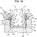
- FIG. 1 Ais a cross sectional view of a ball joint installed in a bearing housing and having an anti pull-out collar of the present invention installed thereon;
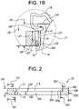
- FIG. 1 Bis a cross sectional view of the anti pull-out collar within circle B in FIG. 1 A including a seal;
- FIG. 2is a cross sectional view of the anti pull-out collar of FIG. 1 A ;
- FIG. 3is a top view of the anti pull-out collar of FIG. 1 A ;
- FIG. 4is a cross sectional view of a prior art ball joint installed in a bearing housing
- FIG. 5is a side sectional view of an alternate embodiment of the anti pull-out collar of FIG. 1 A ;
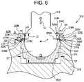
- FIG. 6is a side sectional view of an alternate embodiment of the anti pull-out collar of FIG. 1 A ;
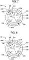
- FIG. 7is a top view of the anti pull-out collar of FIG. 5 ;
- FIG. 8is a top view of the anti pull-out collar of FIG. 6 .
- a ball jointis generally designated by the numeral 10 .
- the ball joint 10includes an outer race 14 having an exterior surface 14 B extending from outer axial end 14 C to inner axial end 14 D thereof.
- the outer race 14has an interior area defined by a spherical inner surface 14 A.
- the interior areahas an opening 14 X proximate the outer axial end 14 C.
- the outer race 14is closed at the inner axial end 14 D.
- the ball jointincludes an inner member that has a spherical ball 11 that has a stem 12 extending therefrom and extending outwardly from the opening 14 X.
- the ball 11has a spherical outer surface 11 E.
- a portion of (e.g., 70 to 90 percent) the ball 11is disposed in the interior area with the spherical outer surface 11 E slidingly engaging the spherical inner surface 14 A of the outer race 14 to facilitate angular misalignment of the ball 11 and stem 12 relative to the outer race 14 .
- the ball 11is contained in the interior area of the outer race 14 by the spherical inner surface 14 A which extends over the spherical outer surface 11 E towards the stem 12 beyond a center point P of the ball 11 .
- the exterior surface 14 B of the outer race 14has a flange 14 F extending radially outward from and circumferentially around the exterior surface 14 B proximate the outer axial end 14 C.
- the flange 14 Fhas a shoulder 14 G facing axially towards the inner axial end 14 D of the outer race 14 and having an outer circumferential surface 14 H.
- the exterior surface 14 B of the outer race 14has a segment 14 K that engages a portion of an anti pull-out collar 20 , as described herein.
- the outer race 14is disposed in an interior area 16 K (e.g., a receiving area) of a bearing housing 16 which has an opening 16 Q located at an end thereof.
- the exterior surface 14 B of the outer race 14has an outside diameter D 6 .
- the exterior surface 14 Gengages a cylindrical interior surface 16 A of the bearing housing 16 .
- the cylindrical interior surface 16 Ahas an inside diameter D 7 that is slightly less (e.g., 0.002 to 0.004 inches) than the outside diameter D 6 to cause the outer race 14 to be press fit (i.e., interference fit) into the bearing housing 16 .
- the outer race 14has an overall axial length L 1 that extends between the first axial end 14 C to the second axial end 14 D.
- the first axial end 14 C of the outer race 14protrudes out of the housing 16 at an opening 16 Q thereof, a distance L 44 that is about 20 to about 25 percent of the overall axial length L 1 of the outer race 14 .
- the outside diameter D 29 of the anti pull-out collaris greater than the inside diameter D 7 of the cylindrical interior surface 16 A of the housing 16 .
- the inside diameter D 22 of the second section 22 of the anti pull-out collar 20is about equal to the inside diameter D 7 of the cylindrical interior surface 16 A of the housing 16 .
- the inside diameter D 21 of the first section 22 of the anti pull-out collar 20is greater than the inside diameter D 7 of the cylindrical interior surface 16 A of the housing 16 .
- the anti pull-out collar 20 of the present inventionis disposed around the outer race 14 proximate the flange 14 F, as described herein.
- the entire anti pull-out collar 20is located beyond the center point P of the ball 11 towards the first axial end 14 C of the outer race 14 .
- the anti pull-out collar 20establishes a torque stabilization feature configured to maintain operating torque (e.g., torque required to misalign the ball 11 relative to the outer race 14 ) of the ball joint 10 within a predetermined range.
- the anti pull-out collar 20is in the form of an annular ring that has a radially inward facing inside surface 20 A that extends an overall axial length L 43 between a first axial end 20 B and a second axial end 20 C of the anti pull-out collar 20 .
- the radially inward facing surface 20 Ahas a profile that is complementary in shape to the exterior surface 14 B of the outer race 14 .
- the anti pull-out collar 20engages the outer race 14 along a length L 43 ′ which is about equal to the overall axial length L 43 .
- the anti pull-out collar 20has a radial thickness T 21 and T 22 (see FIGS.
- the anti pull-out collar 20is circumferentially continuous.
- the profile of the anti pull-out collar 20is defined by a first section 21 having a first inside diameter D 21 and a second section 22 having a second inside diameter D 22 .
- the first inside diameter D 21is greater than the second inside diameter D 22 .
- An axially facing abutment surface 20 Gextends between the first section 21 and the second section 22 .
- the abutment surface 20 Gis axially facing towards the first axial end 20 B.
- the radial thickness T 21occurs in the first section 21 and extends between an inside surface 21 A of the first section 21 and an exterior surface 20 E of the anti pull-out collar 20 .
- the exterior surface 20 Eis exposed.
- the radial thickness T 22occurs in the second section 22 and extends between an inside surface 22 A of the second section 22 and the exterior surface 22 E of the anti pull-out collar 20 .
- the first section 21extends an axial length L 21 between the first axial end 20 B and the abutment surface 20 G.
- the second section 22extends an axial length L 22 between the second axial end 20 C and the abutment surface 20 G.
- the axial length L 21is about 60 to about 70 percent of the overall axial length L 43 .
- the second axial end 20 C of the anti pull-out collar 20engages an axial face 16 Y of the housing 16 .
- the anti pull-out collar 20engages a portion of the exterior surface 14 B of the outer race 14 .
- the outer circumferential surface 14 Hengages (e.g., frictionally engages) the inside surface 21 A of the first section 21 ;
- the shoulder 14 Gengages the abutment surface 20 G;
- the segment 14 Kengages (e.g., frictionally engages) the inside surface 22 A of the second section 22 .
- the second section 22 of the anti pull-out collar 20is disposed axially between an axial face 16 Y of the bearing housing 16 and the shoulder 14 G of the flange 14 F.
- the shoulder 14 G of the outer race 14faces axially toward the axial face 16 Y of the housing.
- the abutment surface 20 G of the anti pull-out collar 20faces axially away from the axial face 16 Y of the housing 16 .
- the circumferential surface 14 Hhas an outside diameter D 4 that is slightly greater than the inside diameter D 21 of the first section 21 to create an interference fit therebetween.
- the segment 14 Khas an outside diameter D 3 that is slightly greater than the inside diameter D 22 of the second section 22 to create an interference fit therebetween.
- the interference fitprovides a retention feature configured to retain the anti pull-out collar 20 on the exterior surface 14 B of the outer race 14 and has utility in ensuring the anti pull-out collar 20 is secured to the outer race 14 during shipping and installation of the ball joint 10 in the housing 16 .
- the interference fithas further utility by imparting compressive stresses on the outer race 14 and the anti pull-out collar 20 to increase fatigue resistance thereof.
- the anti pull-out collar 20is manufactured from a metallic material (e.g. an iron based alloy such as steel) that is heat treated to obtain predetermined stiffness and fatigue resistance.
- the outer race 14 , the spherical ball 11 and the stem 12are made from a metallic material (e.g. an iron based alloy such as steel).
- other materialsmay be employed including but not limited to copper based alloys such as brass or bronze, titanium and composite materials.
- FIG. 1 Bdepicts the first axial end 14 C of the outer race 14 in greater detail.
- a seal receiving groove 14 Pis incorporated into the outer race 14 between the flange 14 F and the first axial end 14 C.
- the seal receiving groove 14 Pfaces radially outward from the outer race 14 away from the ball 11 .
- One end of a seal 18is seated in the seal receiving groove 14 P.
- the seal 18extends toward the stem 12 and contacts (e.g., slidingly engages) the ball 11 .
- the seal 18prevents outside contaminants from entering the interface between the outer race 14 and the ball 11 and in some embodiments retains lubricant between the outer race 14 and ball 11 .
- the methodincludes providing a ball joint 10 having an outer race 14 with an inner member having a ball portion 11 disposed partially in the outer race 14 and contained in the outer race 14 .
- the methodincludes installing an anti pull-out collar 20 around a portion of the outer member 14 to withstand (e.g., counteract, prevent or mitigate) radial expansion of the outer race in response to pull-out forces Q applied to the ball 11 and thereby increasing the load capacity of the ball joint 10 .
- FIG. 5depicts an alternate embodiment of an outer race 214 and anti pull-out collar 220 . Elements similar in structure to those discussed with respect to FIG. 1 A are depicted in FIG. 5 with the numeral “ 2 ” immediately preceding the reference numeral. The discussion of these elements with respect to FIG. 1 A is incorporated herein by reference and the differences between the embodiments are discussed in detail as follows.
- the seal receiving groove 220 Pis incorporated into the radially exterior surface 220 E of the anti pull-out collar 220 .
- a flange 214 Fextends radially outward from the outer race 214 and is located proximate the outer axial end 214 C of the outer race 214 .
- the flange 214 Fhas an outside diameter D 8 that is greater than the inside diameter D 7 of the cylindrical interior surface 16 A of the housing 16 .
- the anti pull-out collar 220is secured to the outer race 214 and the flange 214 F axially retains the anti pull-out collar 220 against the bearing housing 216 .
- a shoulder 214 G of the flange 214 Flimits the axial travel of anti pull-out collar 220 .
- the outer circumferential surface 214 H of the outer race 214is secured to the inside surface 220 A of the anti pull-out collar 220 by a threaded connection.
- the outer circumferential surface 214 Hhas an outside diameter D 5 that is about the same as an inside diameter D 233 of the inside surface 220 A of the anti pull-out collar 220 .
- the anti pull-out collar 220is threaded on to the outer ring 214 so that the axial end 220 B engages the shoulder 214 G of the flange 214 F, before the outer ring 214 is press fit into the housing 216 .
- Other connection means between the outer circumferential surface 214 H and the inside surface 220 Ado not substantially depart from the invention disclosed herein.
- the anti pull-out collar 220is disposed around the outer race 214 proximate the flange 214 F, as described herein.
- the anti pull-out collarestablishes a torque stabilization feature configured to maintain operating torque (e.g., torque required to misalign the ball 211 relative to the outer race 214 ) of the ball joint 210 within a predetermined range.
- the anti pull-out collar 220has a radial thickness T 21 and T 22 (see FIG. 7 as described below) configured to prevent radial expansion of the outer race 214 of the ball joint 210 that results in failure of the ball joint 210 due to pull-out of the ball 211 and stem 212 from the outer race 214 , in response to pull-out loads Q applied thereto.
- the first axial end 214 C of the outer race 214protrudes out of the housing 216 at an opening 216 Q thereof, a distance L 44 that is about 25 to about 30 percent of the overall axial length L 1 of the outer race 214 .
- FIG. 6depicts an alternate embodiment of the outer race 314 with the flange 314 F spaced axially away from the first axial end 314 C. Elements similar in structure to those discussed with respect to FIG. 1 A are depicted in FIG. 6 with the numeral “ 3 ” immediately preceding the reference numeral. The discussion of these elements with respect to FIG. 1 A is incorporated herein by reference and the differences between the embodiments are discussed in detail as follows.
- the seal receiving groove 320 Pis incorporated into the radially exterior surface 320 E of the anti pull-out collar 320 .
- the anti pull-out collar 320is secured to the outer race 314 and the anti pull-out collar 320 retains the flange 314 F in the axial direction.
- a shoulder 314 G of the flange 314 Flimits axial travel of the anti pull-out collar 320 .
- the anti pull-out collar 320is threaded on to the outer ring 314 so that the anti pull-out collar 320 engages the shoulder 314 G.
- the anti pull-out collaris installable over the outer ring 314 with the outer ring 314 installed in the housing 316 or with the outer ring 314 removed from the housing.
- Other connection means between the outer circumferential surface 314 H and the inside surface 320 Ado not substantially depart from the invention disclosed herein.
- the first axial end 314 C of the outer race 314protrudes out of the housing 316 at an opening 316 Q thereof, a distance L 44 that is about 25 about 30 percent of the overall axial length L 1 of the outer race 314 .
- the anti pull-out collar 320is installable over (e.g., can fit over, be threaded over or press fit over) the second inside diameter D 5 of the outer ring 314 .
- the anti pull-out collar 220 , 320is in the form of an annular ring that has a radially inward facing inside surface 220 A, 320 A that extends between a first axial end 220 B, 320 B and a second axial end 220 C, 320 C of the anti pull-out collar 220 , 320 .
- the radially inward facing surface 220 A, 320 Ahas a profile that is complementary in shape to the outer circumferential surface 214 H, 314 H of the outer race 214 , 314 , respectively.
- the shoulder 214 Gis axially facing towards the inner axial end 214 D of the outer race 214 .
- the shoulder 314 Gis axially facing towards the outer axial end 314 C of the outer race 314 .
- the anti pull-out collar 220has an overall radial thickness T 230 that extends between the inside surface 220 A and the exterior surface 220 E of the anti pull-out collar 220 adjacent the second axial end 220 C (see FIG. 5 ).
- the anti pull-out collar 220has an overall outside diameter D 230 .
- the anti pull-out collar 220has a seal receiving groove 220 P formed therein adjacent to the third axial end 220 B.
- the seal receiving groove 220 Phas a base portion 223 E (e.g., innermost extremity) and a lip 229 that extends radially outward to a circumferential exterior surface 222 E which has an outside diameter D 222 .
- the lip 229has a radial thickness T 222 that extends between the inside surface 220 A and the exterior surface 222 E of the anti pull-out collar 220 adjacent the first axial end 220 B.
- the seal receiving groove 220 Phas a radial thickness T 223 measured between the inside surface 220 A and the base portion 223 E.
- the inside diameter D 233 of the anti pull-out collar 220is about equal to the outside diameter D 5 of the outer race 214 .
- the outside diameter D 222is less than the outside diameter D 230 of the anti pull-out collar 220 .
- the thickness T 230is greater than the thickness T 222 which is greater than the thickness T 223 .
- the outside diameter D 5 of the outer race 214is greater than the inside diameter D 7 of the housing 316 .
- the anti pull-out collar 320has an overall radial thickness T 330 that extends between the inside surface 320 A and the exterior surface 320 E of the anti pull-out collar 320 adjacent the second axial end 320 C (see FIG. 6 ).
- the anti pull-out collar 320has an overall outside diameter D 330 .
- the anti pull-out collar 320has a seal receiving groove 320 P formed therein adjacent to the third axial end 320 B.
- the seal receiving groove 320 Phas a base portion 323 E (e.g., innermost extremity) and a lip 329 that extends radially outward to a circumferential exterior surface 322 E which has an outside diameter D 322 .
- the lip 329has a radial thickness T 322 that extends between the inside surface 320 A and the exterior surface 322 E of the anti pull-out collar 320 adjacent the first axial end 320 B.
- the seal receiving groove 320 Phas a radial thickness T 323 measured between the inside surface 320 A and the base portion 323 E.
- the inside diameter D 333 of the anti pull-out collar 320is about equal to the outside diameter D 5 of the outer race 314 .
- the outside diameter D 322is less than the outside diameter D 330 of the anti pull-out collar 320 .
- the thickness T 330is greater than the thickness T 322 which is greater than the thickness T 323 .
- the outside diameter D 5 of the outer race 314is less than the inside diameter D 7 of the housing 316 .
Landscapes
- Engineering & Computer Science (AREA)
- General Engineering & Computer Science (AREA)
- Mechanical Engineering (AREA)
- Pivots And Pivotal Connections (AREA)
- Steering-Linkage Mechanisms And Four-Wheel Steering (AREA)
Abstract
Description
Claims (22)
Priority Applications (1)
| Application Number | Priority Date | Filing Date | Title |
|---|---|---|---|
| US16/552,349US11549552B2 (en) | 2018-08-29 | 2019-08-27 | Anti pull-out collar for a ball joint |
Applications Claiming Priority (2)
| Application Number | Priority Date | Filing Date | Title |
|---|---|---|---|
| US201862724280P | 2018-08-29 | 2018-08-29 | |
| US16/552,349US11549552B2 (en) | 2018-08-29 | 2019-08-27 | Anti pull-out collar for a ball joint |
Publications (2)
| Publication Number | Publication Date |
|---|---|
| US20200072277A1 US20200072277A1 (en) | 2020-03-05 |
| US11549552B2true US11549552B2 (en) | 2023-01-10 |
Family
ID=67742293
Family Applications (1)
| Application Number | Title | Priority Date | Filing Date |
|---|---|---|---|
| US16/552,349Active2039-11-15US11549552B2 (en) | 2018-08-29 | 2019-08-27 | Anti pull-out collar for a ball joint |
Country Status (2)
| Country | Link |
|---|---|
| US (1) | US11549552B2 (en) |
| EP (2) | EP3620675B1 (en) |
Families Citing this family (3)
| Publication number | Priority date | Publication date | Assignee | Title |
|---|---|---|---|---|
| US11788575B2 (en)* | 2018-05-18 | 2023-10-17 | Federal-Mogul Motorparts Llc | Socket assembly with a retention device |
| US12196258B2 (en) | 2021-11-12 | 2025-01-14 | Roller Bearing Company Of America, Inc. | Spherical plain bearing with angular misalignment restraint system, and angular misalignment restrain system |
| WO2025081248A1 (en)* | 2023-10-20 | 2025-04-24 | Viemar Industria E Comércio Ltda | Stabiliser bar tie rod and method for assembling and disassembling a stabiliser bar tie rod |
Citations (46)
| Publication number | Priority date | Publication date | Assignee | Title |
|---|---|---|---|---|
| US3091486A (en)* | 1960-07-14 | 1963-05-28 | Gen Motors Corp | Ball joint |
| US3216754A (en) | 1962-03-26 | 1965-11-09 | O & S Bearing & Mfg Co | Ball joint |
| US3269758A (en)* | 1964-01-29 | 1966-08-30 | Lemfoerder Metallwaren Ag | Ball joint device |
| US3442561A (en)* | 1964-08-06 | 1969-05-06 | Citroen Sa Andre | Rotary joints |
| US3574368A (en)* | 1970-01-16 | 1971-04-13 | Perfect Equip Corp | Preloaded ball joint |
| US4410295A (en)* | 1981-02-05 | 1983-10-18 | Lemforder Metallwaren AG Lemforde | Universal joint construction |
| US4666330A (en) | 1985-12-04 | 1987-05-19 | Tuthill Corporation | Ball joint assembly |
| US4676798A (en)* | 1984-09-12 | 1987-06-30 | Joint Medical Products Corporation | Socket bearing assembly for a constrained ball and socket joint |
| US4679958A (en) | 1981-10-23 | 1987-07-14 | Nifco, Inc. | Ball joint |
| US4718911A (en)* | 1986-02-19 | 1988-01-12 | Pfizer Hospital Products Group Inc. | Acetabular cup assembly |
| US4784663A (en)* | 1986-02-19 | 1988-11-15 | Pfizer Hospital Products Group, Inc. | Acetabular cup assembly |
| US5154530A (en)* | 1991-03-05 | 1992-10-13 | Trw Inc. | Ball joint |
| US5267805A (en) | 1991-12-16 | 1993-12-07 | Musashi Seimitsu Kogyo Company Limited | Synthetic resin ball joint with metal reinforcing ring |
| US5395176A (en)* | 1992-04-09 | 1995-03-07 | Mercedes-Benz Ag | Ball joint for parts of the steering or wheel suspension of motor vehicles |
| DE4445251A1 (en)* | 1994-12-19 | 1996-01-11 | Daimler Benz Ag | Fastening arrangement between an inner part and an outer part |
| US5678947A (en)* | 1995-09-26 | 1997-10-21 | Trw Inc. | Joint assembly |
| US5824108A (en)* | 1997-03-26 | 1998-10-20 | Johnson & Johnson Professional, Inc. | Bipolar acetabular cup |
| US6010271A (en) | 1996-02-01 | 2000-01-04 | Trw Inc. | Joint assembly |
| DE19842198A1 (en)* | 1998-09-15 | 2000-04-06 | Lemfoerder Metallwaren Ag | Ball and socket joint has housing with cavity containing link pin with ball, bearing shell between housing and ball, and flange-like closure ring |
| US6093208A (en)* | 1998-05-12 | 2000-07-25 | Tian; Enrico | Antiluxation hip prosthesis |
| FR2789359A1 (en) | 1999-02-04 | 2000-08-11 | Mecanique De Villeurbanne Soc | BALL JOINT, PARTICULARLY A STEERING BALL OR SUSPENSION BALL FOR MOTOR VEHICLES, AND METHOD FOR MANUFACTURING A PAD FOR SUCH A BALL JOINT |
| US6164829A (en)* | 1998-05-28 | 2000-12-26 | Trw Fahrwerksysteme Gmbh & Co. Kg | Bearing shell |
| US20020114660A1 (en) | 2001-02-16 | 2002-08-22 | Burton John E. | Ball socket with improved pull-out force resistance |
| EP0793782B1 (en) | 1995-08-01 | 2002-09-25 | MacLEAN-FOGG COMPANY | Ball joint link and method of producing same |
| US20030077114A1 (en)* | 2000-02-09 | 2003-04-24 | Broeker Klaus | Ball joint |
| US20040047677A1 (en)* | 2001-10-09 | 2004-03-11 | Stefan Schonhoff | Ball-and-socket joint |
| US20040057781A1 (en)* | 2001-10-04 | 2004-03-25 | Manfred Bohne | Balljoint |
| US20050036827A1 (en)* | 2002-09-11 | 2005-02-17 | Zf Lemforder Metallwaren Ag. | Ball and socket joint protective cap |
| US20050105961A1 (en)* | 2001-12-25 | 2005-05-19 | Yasuhiro Kondoh | Ball joint |
| US6902345B2 (en)* | 2001-08-10 | 2005-06-07 | Audi Ag | Ball joint |
| US7040833B2 (en)* | 2001-10-29 | 2006-05-09 | Musashi Seimitsu Kogyo Kabushiki Kaisha | Ball joint |
| WO2006105928A1 (en) | 2005-04-06 | 2006-10-12 | Daimlerchrysler Ag | Ball-and-socket joint |
| US7192214B2 (en)* | 2002-03-28 | 2007-03-20 | ZF Lemörder Metallwaren AG | Sealing bellows with snap-on connection |
| US7357591B2 (en)* | 2002-01-11 | 2008-04-15 | ZF Lemförder Metallwaren AG | Ball-and-socket joint |
| DE102008031499A1 (en)* | 2007-07-05 | 2009-01-08 | Musashi Seimitsu Industry Co., Ltd., Toyohashi | Method for mounting bags involves mounting on sleeves with large and small diameters and adapted to bearing linkage |
| DE102007037270A1 (en)* | 2007-08-07 | 2009-02-12 | Bayerische Motoren Werke Aktiengesellschaft | Ball joint arrangement for functioning as supporting joint in pivot bearing of chassis of vehicle, has nut screwed on thread section of support shell supported by outer wall section in form of convex ball layer |
| US20090082116A1 (en) | 2007-07-04 | 2009-03-26 | Bernhard Baechle | Retainer pin for drive shaft |
| WO2009038566A1 (en) | 2007-09-21 | 2009-03-26 | Deere & Company | Ball-and-socket joint for work vehicle |
| US8137021B2 (en)* | 2006-11-03 | 2012-03-20 | Zf Friedrichshafen Ag | Sealing element for a ball and socket joint |
| US8770882B2 (en)* | 2008-06-04 | 2014-07-08 | Zf Friedrichshafen Ag | Ball joint |
| US8851785B1 (en)* | 2009-11-17 | 2014-10-07 | Trw Automotive U.S. Llc | Ball joint |
| US9056538B2 (en)* | 2012-02-16 | 2015-06-16 | Nhk Spring Co., Ltd. | Stabilizer link and manufacturing method therefor |
| US9140294B2 (en) | 2012-03-06 | 2015-09-22 | Burton Technologies, Llc | High extraction force ball socket |
| US20160084299A1 (en) | 2014-09-18 | 2016-03-24 | Rane (Madras) Limited | Fail safe ball joint |
| US9476447B2 (en) | 2008-05-21 | 2016-10-25 | Federal-Mogul Powertrain, Inc. | Ball joint assembly and method of making |
| US20180163775A1 (en)* | 2015-06-16 | 2018-06-14 | Zf Friedrichshafen Ag | Ball joint |
- 2019
- 2019-08-23EPEP19193411.6Apatent/EP3620675B1/ennot_activeNot-in-force
- 2019-08-23EPEP21171123.9Apatent/EP3875793B1/enactiveActive
- 2019-08-27USUS16/552,349patent/US11549552B2/enactiveActive
Patent Citations (51)
| Publication number | Priority date | Publication date | Assignee | Title |
|---|---|---|---|---|
| US3091486A (en)* | 1960-07-14 | 1963-05-28 | Gen Motors Corp | Ball joint |
| US3216754A (en) | 1962-03-26 | 1965-11-09 | O & S Bearing & Mfg Co | Ball joint |
| US3269758A (en)* | 1964-01-29 | 1966-08-30 | Lemfoerder Metallwaren Ag | Ball joint device |
| US3442561A (en)* | 1964-08-06 | 1969-05-06 | Citroen Sa Andre | Rotary joints |
| US3574368A (en)* | 1970-01-16 | 1971-04-13 | Perfect Equip Corp | Preloaded ball joint |
| US4410295A (en)* | 1981-02-05 | 1983-10-18 | Lemforder Metallwaren AG Lemforde | Universal joint construction |
| US4679958A (en) | 1981-10-23 | 1987-07-14 | Nifco, Inc. | Ball joint |
| US4676798A (en)* | 1984-09-12 | 1987-06-30 | Joint Medical Products Corporation | Socket bearing assembly for a constrained ball and socket joint |
| US4666330A (en) | 1985-12-04 | 1987-05-19 | Tuthill Corporation | Ball joint assembly |
| US4784663A (en)* | 1986-02-19 | 1988-11-15 | Pfizer Hospital Products Group, Inc. | Acetabular cup assembly |
| US4718911A (en)* | 1986-02-19 | 1988-01-12 | Pfizer Hospital Products Group Inc. | Acetabular cup assembly |
| US5154530A (en)* | 1991-03-05 | 1992-10-13 | Trw Inc. | Ball joint |
| US5267805A (en) | 1991-12-16 | 1993-12-07 | Musashi Seimitsu Kogyo Company Limited | Synthetic resin ball joint with metal reinforcing ring |
| US5395176A (en)* | 1992-04-09 | 1995-03-07 | Mercedes-Benz Ag | Ball joint for parts of the steering or wheel suspension of motor vehicles |
| DE4445251A1 (en)* | 1994-12-19 | 1996-01-11 | Daimler Benz Ag | Fastening arrangement between an inner part and an outer part |
| EP0793782B1 (en) | 1995-08-01 | 2002-09-25 | MacLEAN-FOGG COMPANY | Ball joint link and method of producing same |
| US5678947A (en)* | 1995-09-26 | 1997-10-21 | Trw Inc. | Joint assembly |
| US6010271A (en) | 1996-02-01 | 2000-01-04 | Trw Inc. | Joint assembly |
| US5824108A (en)* | 1997-03-26 | 1998-10-20 | Johnson & Johnson Professional, Inc. | Bipolar acetabular cup |
| US6093208A (en)* | 1998-05-12 | 2000-07-25 | Tian; Enrico | Antiluxation hip prosthesis |
| US6164829A (en)* | 1998-05-28 | 2000-12-26 | Trw Fahrwerksysteme Gmbh & Co. Kg | Bearing shell |
| DE19842198A1 (en)* | 1998-09-15 | 2000-04-06 | Lemfoerder Metallwaren Ag | Ball and socket joint has housing with cavity containing link pin with ball, bearing shell between housing and ball, and flange-like closure ring |
| US6488436B1 (en) | 1999-02-04 | 2002-12-03 | Societe Mecanique De Villeurbanne | Ball joint, in particular steering or suspension ball joint for motor vehicles and, method for making a bearing for same |
| FR2789359A1 (en) | 1999-02-04 | 2000-08-11 | Mecanique De Villeurbanne Soc | BALL JOINT, PARTICULARLY A STEERING BALL OR SUSPENSION BALL FOR MOTOR VEHICLES, AND METHOD FOR MANUFACTURING A PAD FOR SUCH A BALL JOINT |
| US6773196B2 (en)* | 2000-02-09 | 2004-08-10 | ZF Lemförder Metallwaren AG | Ball joint |
| US20030077114A1 (en)* | 2000-02-09 | 2003-04-24 | Broeker Klaus | Ball joint |
| US20020114660A1 (en) | 2001-02-16 | 2002-08-22 | Burton John E. | Ball socket with improved pull-out force resistance |
| US6902345B2 (en)* | 2001-08-10 | 2005-06-07 | Audi Ag | Ball joint |
| US20040057781A1 (en)* | 2001-10-04 | 2004-03-25 | Manfred Bohne | Balljoint |
| US20040047677A1 (en)* | 2001-10-09 | 2004-03-11 | Stefan Schonhoff | Ball-and-socket joint |
| US7040833B2 (en)* | 2001-10-29 | 2006-05-09 | Musashi Seimitsu Kogyo Kabushiki Kaisha | Ball joint |
| US7260878B2 (en)* | 2001-10-29 | 2007-08-28 | Usashi Seimitsu Kogyo Kabushiki | Ball joint |
| US20050105961A1 (en)* | 2001-12-25 | 2005-05-19 | Yasuhiro Kondoh | Ball joint |
| US7357591B2 (en)* | 2002-01-11 | 2008-04-15 | ZF Lemförder Metallwaren AG | Ball-and-socket joint |
| US7192214B2 (en)* | 2002-03-28 | 2007-03-20 | ZF Lemörder Metallwaren AG | Sealing bellows with snap-on connection |
| US20050036827A1 (en)* | 2002-09-11 | 2005-02-17 | Zf Lemforder Metallwaren Ag. | Ball and socket joint protective cap |
| WO2006105928A1 (en) | 2005-04-06 | 2006-10-12 | Daimlerchrysler Ag | Ball-and-socket joint |
| US8137021B2 (en)* | 2006-11-03 | 2012-03-20 | Zf Friedrichshafen Ag | Sealing element for a ball and socket joint |
| US20090082116A1 (en) | 2007-07-04 | 2009-03-26 | Bernhard Baechle | Retainer pin for drive shaft |
| DE102008031499A1 (en)* | 2007-07-05 | 2009-01-08 | Musashi Seimitsu Industry Co., Ltd., Toyohashi | Method for mounting bags involves mounting on sleeves with large and small diameters and adapted to bearing linkage |
| DE102007037270A1 (en)* | 2007-08-07 | 2009-02-12 | Bayerische Motoren Werke Aktiengesellschaft | Ball joint arrangement for functioning as supporting joint in pivot bearing of chassis of vehicle, has nut screwed on thread section of support shell supported by outer wall section in form of convex ball layer |
| WO2009038566A1 (en) | 2007-09-21 | 2009-03-26 | Deere & Company | Ball-and-socket joint for work vehicle |
| US9476447B2 (en) | 2008-05-21 | 2016-10-25 | Federal-Mogul Powertrain, Inc. | Ball joint assembly and method of making |
| US20170102028A1 (en) | 2008-05-21 | 2017-04-13 | Federal-Mogul Motorparts Corporation | Ball joint assembly and method of making |
| US10309449B2 (en) | 2008-05-21 | 2019-06-04 | Federal-Mogul Motorparts Llc | Ball joint assembly and method of making |
| US8770882B2 (en)* | 2008-06-04 | 2014-07-08 | Zf Friedrichshafen Ag | Ball joint |
| US8851785B1 (en)* | 2009-11-17 | 2014-10-07 | Trw Automotive U.S. Llc | Ball joint |
| US9056538B2 (en)* | 2012-02-16 | 2015-06-16 | Nhk Spring Co., Ltd. | Stabilizer link and manufacturing method therefor |
| US9140294B2 (en) | 2012-03-06 | 2015-09-22 | Burton Technologies, Llc | High extraction force ball socket |
| US20160084299A1 (en) | 2014-09-18 | 2016-03-24 | Rane (Madras) Limited | Fail safe ball joint |
| US20180163775A1 (en)* | 2015-06-16 | 2018-06-14 | Zf Friedrichshafen Ag | Ball joint |
Also Published As
| Publication number | Publication date |
|---|---|
| EP3620675A1 (en) | 2020-03-11 |
| EP3875793B1 (en) | 2023-04-19 |
| EP3620675B1 (en) | 2021-12-15 |
| EP3875793A1 (en) | 2021-09-08 |
| US20200072277A1 (en) | 2020-03-05 |
Similar Documents
| Publication | Publication Date | Title |
|---|---|---|
| US11549552B2 (en) | Anti pull-out collar for a ball joint | |
| US7731200B2 (en) | Seal assembly, and rolling bearing and hub unit assembled therewith | |
| US8905641B2 (en) | Hub bearing assembly with a sealing device | |
| US9987880B2 (en) | Bearing assembly | |
| US7708353B2 (en) | Seal assembly for hub flange and slinger | |
| EP3002472B1 (en) | A segmented outer ring for a bearing for mitigating torque degradation | |
| JP3764740B2 (en) | Neck seal | |
| US10473147B2 (en) | Socket assembly and method of making a socket assembly | |
| US9702411B2 (en) | Bearing assembly with split outer ring having interference fit tabs and method of assembly of bearing | |
| WO2013015108A1 (en) | Sealed roller bearing | |
| CN107013568B (en) | Preloaded bearing combination unit | |
| US11441597B2 (en) | Socket assembly with a pressed cover plate and method of construction thereof | |
| KR101734691B1 (en) | A Flinger For Bearing Having Preventing Means for Bending | |
| US10584742B2 (en) | Rolling bearing | |
| US10527090B2 (en) | Wheel bearing unit and pre-assembly method | |
| JP2008018767A (en) | Drive shaft assembly | |
| US8388230B2 (en) | Seal guard | |
| JP2017223253A (en) | Manufacturing method of wheel bearing device | |
| CN111706612A (en) | Bearing assembly with cylindrical rolling elements | |
| US20250043827A1 (en) | Wheel hub unit | |
| KR102022371B1 (en) | A Rolling Bearing Having Seal | |
| US7429135B2 (en) | Roller bearing assembly |
Legal Events
| Date | Code | Title | Description |
|---|---|---|---|
| FEPP | Fee payment procedure | Free format text:ENTITY STATUS SET TO UNDISCOUNTED (ORIGINAL EVENT CODE: BIG.); ENTITY STATUS OF PATENT OWNER: LARGE ENTITY | |
| AS | Assignment | Owner name:SCHAUBLIN SA, SWITZERLAND Free format text:ASSIGNMENT OF ASSIGNORS INTEREST;ASSIGNORS:WILHELM, CHRIS;TOSCANO, GIROLAMO;SIGNING DATES FROM 20191003 TO 20191008;REEL/FRAME:050946/0949 | |
| STPP | Information on status: patent application and granting procedure in general | Free format text:NON FINAL ACTION MAILED | |
| STPP | Information on status: patent application and granting procedure in general | Free format text:RESPONSE TO NON-FINAL OFFICE ACTION ENTERED AND FORWARDED TO EXAMINER | |
| STPP | Information on status: patent application and granting procedure in general | Free format text:FINAL REJECTION MAILED | |
| STPP | Information on status: patent application and granting procedure in general | Free format text:DOCKETED NEW CASE - READY FOR EXAMINATION | |
| STPP | Information on status: patent application and granting procedure in general | Free format text:NON FINAL ACTION MAILED | |
| STPP | Information on status: patent application and granting procedure in general | Free format text:RESPONSE TO NON-FINAL OFFICE ACTION ENTERED AND FORWARDED TO EXAMINER | |
| STPP | Information on status: patent application and granting procedure in general | Free format text:FINAL REJECTION MAILED | |
| STPP | Information on status: patent application and granting procedure in general | Free format text:RESPONSE AFTER FINAL ACTION FORWARDED TO EXAMINER | |
| STPP | Information on status: patent application and granting procedure in general | Free format text:NOTICE OF ALLOWANCE MAILED -- APPLICATION RECEIVED IN OFFICE OF PUBLICATIONS | |
| STPP | Information on status: patent application and granting procedure in general | Free format text:PUBLICATIONS -- ISSUE FEE PAYMENT VERIFIED | |
| STCF | Information on status: patent grant | Free format text:PATENTED CASE |