US11549464B2 - Hybrid gas turbine engine starting control - Google Patents
Hybrid gas turbine engine starting controlDownload PDFInfo
- Publication number
- US11549464B2 US11549464B2US16/936,602US202016936602AUS11549464B2US 11549464 B2US11549464 B2US 11549464B2US 202016936602 AUS202016936602 AUS 202016936602AUS 11549464 B2US11549464 B2US 11549464B2
- Authority
- US
- United States
- Prior art keywords
- spool
- low
- thrust
- motor
- gas turbine
- Prior art date
- Legal status (The legal status is an assumption and is not a legal conclusion. Google has not performed a legal analysis and makes no representation as to the accuracy of the status listed.)
- Active
Links
- 239000000446fuelSubstances0.000claimsabstractdescription59
- 230000004044responseEffects0.000claimsdescription24
- 238000000034methodMethods0.000claimsdescription19
- 230000005540biological transmissionEffects0.000claimsdescription7
- 230000007704transitionEffects0.000claimsdescription6
- 238000002485combustion reactionMethods0.000claims2
- 230000000977initiatory effectEffects0.000claims2
- 238000004146energy storageMethods0.000description13
- 239000012636effectorSubstances0.000description7
- 239000003990capacitorSubstances0.000description4
- 230000003750conditioning effectEffects0.000description4
- 238000010586diagramMethods0.000description4
- 238000012545processingMethods0.000description4
- 238000012546transferMethods0.000description3
- 230000008859changeEffects0.000description2
- 230000000694effectsEffects0.000description2
- 230000005611electricityEffects0.000description2
- 230000006870functionEffects0.000description2
- 239000000203mixtureSubstances0.000description2
- 230000008901benefitEffects0.000description1
- 238000004891communicationMethods0.000description1
- 230000006835compressionEffects0.000description1
- 238000007906compressionMethods0.000description1
- 230000009977dual effectEffects0.000description1
- 239000000463materialSubstances0.000description1
- 238000005259measurementMethods0.000description1
- 238000012986modificationMethods0.000description1
- 230000004048modificationEffects0.000description1
- 230000003287optical effectEffects0.000description1
- 238000010248power generationMethods0.000description1
- 230000008569processEffects0.000description1
- 230000002277temperature effectEffects0.000description1
Images


Classifications
- F—MECHANICAL ENGINEERING; LIGHTING; HEATING; WEAPONS; BLASTING
- F02—COMBUSTION ENGINES; HOT-GAS OR COMBUSTION-PRODUCT ENGINE PLANTS
- F02C—GAS-TURBINE PLANTS; AIR INTAKES FOR JET-PROPULSION PLANTS; CONTROLLING FUEL SUPPLY IN AIR-BREATHING JET-PROPULSION PLANTS
- F02C7/00—Features, components parts, details or accessories, not provided for in, or of interest apart form groups F02C1/00 - F02C6/00; Air intakes for jet-propulsion plants
- F02C7/26—Starting; Ignition
- F02C7/268—Starting drives for the rotor, acting directly on the rotor of the gas turbine to be started
- F02C7/275—Mechanical drives
- B—PERFORMING OPERATIONS; TRANSPORTING
- B64—AIRCRAFT; AVIATION; COSMONAUTICS
- B64D—EQUIPMENT FOR FITTING IN OR TO AIRCRAFT; FLIGHT SUITS; PARACHUTES; ARRANGEMENT OR MOUNTING OF POWER PLANTS OR PROPULSION TRANSMISSIONS IN AIRCRAFT
- B64D27/00—Arrangement or mounting of power plants in aircraft; Aircraft characterised by the type or position of power plants
- B64D27/02—Aircraft characterised by the type or position of power plants
- B64D27/16—Aircraft characterised by the type or position of power plants of jet type
- B64D27/18—Aircraft characterised by the type or position of power plants of jet type within, or attached to, wings
- B—PERFORMING OPERATIONS; TRANSPORTING
- B64—AIRCRAFT; AVIATION; COSMONAUTICS
- B64D—EQUIPMENT FOR FITTING IN OR TO AIRCRAFT; FLIGHT SUITS; PARACHUTES; ARRANGEMENT OR MOUNTING OF POWER PLANTS OR PROPULSION TRANSMISSIONS IN AIRCRAFT
- B64D27/00—Arrangement or mounting of power plants in aircraft; Aircraft characterised by the type or position of power plants
- B64D27/02—Aircraft characterised by the type or position of power plants
- B64D27/30—Aircraft characterised by electric power plants
- B64D27/31—Aircraft characterised by electric power plants within, or attached to, wings
- B—PERFORMING OPERATIONS; TRANSPORTING
- B64—AIRCRAFT; AVIATION; COSMONAUTICS
- B64D—EQUIPMENT FOR FITTING IN OR TO AIRCRAFT; FLIGHT SUITS; PARACHUTES; ARRANGEMENT OR MOUNTING OF POWER PLANTS OR PROPULSION TRANSMISSIONS IN AIRCRAFT
- B64D27/00—Arrangement or mounting of power plants in aircraft; Aircraft characterised by the type or position of power plants
- B64D27/02—Aircraft characterised by the type or position of power plants
- B64D27/30—Aircraft characterised by electric power plants
- B64D27/33—Hybrid electric aircraft
- B—PERFORMING OPERATIONS; TRANSPORTING
- B64—AIRCRAFT; AVIATION; COSMONAUTICS
- B64D—EQUIPMENT FOR FITTING IN OR TO AIRCRAFT; FLIGHT SUITS; PARACHUTES; ARRANGEMENT OR MOUNTING OF POWER PLANTS OR PROPULSION TRANSMISSIONS IN AIRCRAFT
- B64D31/00—Power plant control systems; Arrangement of power plant control systems in aircraft
- B64D31/16—Power plant control systems; Arrangement of power plant control systems in aircraft for electric power plants
- B64D31/18—Power plant control systems; Arrangement of power plant control systems in aircraft for electric power plants for hybrid-electric power plants
- F—MECHANICAL ENGINEERING; LIGHTING; HEATING; WEAPONS; BLASTING
- F01—MACHINES OR ENGINES IN GENERAL; ENGINE PLANTS IN GENERAL; STEAM ENGINES
- F01D—NON-POSITIVE DISPLACEMENT MACHINES OR ENGINES, e.g. STEAM TURBINES
- F01D19/00—Starting of machines or engines; Regulating, controlling, or safety means in connection therewith
- F—MECHANICAL ENGINEERING; LIGHTING; HEATING; WEAPONS; BLASTING
- F01—MACHINES OR ENGINES IN GENERAL; ENGINE PLANTS IN GENERAL; STEAM ENGINES
- F01D—NON-POSITIVE DISPLACEMENT MACHINES OR ENGINES, e.g. STEAM TURBINES
- F01D25/00—Component parts, details, or accessories, not provided for in, or of interest apart from, other groups
- F01D25/34—Turning or inching gear
- F01D25/36—Turning or inching gear using electric motors
- F—MECHANICAL ENGINEERING; LIGHTING; HEATING; WEAPONS; BLASTING
- F02—COMBUSTION ENGINES; HOT-GAS OR COMBUSTION-PRODUCT ENGINE PLANTS
- F02C—GAS-TURBINE PLANTS; AIR INTAKES FOR JET-PROPULSION PLANTS; CONTROLLING FUEL SUPPLY IN AIR-BREATHING JET-PROPULSION PLANTS
- F02C6/00—Plural gas-turbine plants; Combinations of gas-turbine plants with other apparatus; Adaptations of gas-turbine plants for special use
- F—MECHANICAL ENGINEERING; LIGHTING; HEATING; WEAPONS; BLASTING
- F02—COMBUSTION ENGINES; HOT-GAS OR COMBUSTION-PRODUCT ENGINE PLANTS
- F02C—GAS-TURBINE PLANTS; AIR INTAKES FOR JET-PROPULSION PLANTS; CONTROLLING FUEL SUPPLY IN AIR-BREATHING JET-PROPULSION PLANTS
- F02C7/00—Features, components parts, details or accessories, not provided for in, or of interest apart form groups F02C1/00 - F02C6/00; Air intakes for jet-propulsion plants
- F02C7/26—Starting; Ignition
- F—MECHANICAL ENGINEERING; LIGHTING; HEATING; WEAPONS; BLASTING
- F02—COMBUSTION ENGINES; HOT-GAS OR COMBUSTION-PRODUCT ENGINE PLANTS
- F02C—GAS-TURBINE PLANTS; AIR INTAKES FOR JET-PROPULSION PLANTS; CONTROLLING FUEL SUPPLY IN AIR-BREATHING JET-PROPULSION PLANTS
- F02C7/00—Features, components parts, details or accessories, not provided for in, or of interest apart form groups F02C1/00 - F02C6/00; Air intakes for jet-propulsion plants
- F02C7/32—Arrangement, mounting, or driving, of auxiliaries
- F—MECHANICAL ENGINEERING; LIGHTING; HEATING; WEAPONS; BLASTING
- F02—COMBUSTION ENGINES; HOT-GAS OR COMBUSTION-PRODUCT ENGINE PLANTS
- F02C—GAS-TURBINE PLANTS; AIR INTAKES FOR JET-PROPULSION PLANTS; CONTROLLING FUEL SUPPLY IN AIR-BREATHING JET-PROPULSION PLANTS
- F02C7/00—Features, components parts, details or accessories, not provided for in, or of interest apart form groups F02C1/00 - F02C6/00; Air intakes for jet-propulsion plants
- F02C7/36—Power transmission arrangements between the different shafts of the gas turbine plant, or between the gas-turbine plant and the power user
- F—MECHANICAL ENGINEERING; LIGHTING; HEATING; WEAPONS; BLASTING
- F02—COMBUSTION ENGINES; HOT-GAS OR COMBUSTION-PRODUCT ENGINE PLANTS
- F02C—GAS-TURBINE PLANTS; AIR INTAKES FOR JET-PROPULSION PLANTS; CONTROLLING FUEL SUPPLY IN AIR-BREATHING JET-PROPULSION PLANTS
- F02C9/00—Controlling gas-turbine plants; Controlling fuel supply in air- breathing jet-propulsion plants
- F02C9/26—Control of fuel supply
- F02C9/28—Regulating systems responsive to plant or ambient parameters, e.g. temperature, pressure, rotor speed
- F—MECHANICAL ENGINEERING; LIGHTING; HEATING; WEAPONS; BLASTING
- F02—COMBUSTION ENGINES; HOT-GAS OR COMBUSTION-PRODUCT ENGINE PLANTS
- F02K—JET-PROPULSION PLANTS
- F02K5/00—Plants including an engine, other than a gas turbine, driving a compressor or a ducted fan
- B64D2027/026—
- B—PERFORMING OPERATIONS; TRANSPORTING
- B64—AIRCRAFT; AVIATION; COSMONAUTICS
- B64D—EQUIPMENT FOR FITTING IN OR TO AIRCRAFT; FLIGHT SUITS; PARACHUTES; ARRANGEMENT OR MOUNTING OF POWER PLANTS OR PROPULSION TRANSMISSIONS IN AIRCRAFT
- B64D27/00—Arrangement or mounting of power plants in aircraft; Aircraft characterised by the type or position of power plants
- B64D27/02—Aircraft characterised by the type or position of power plants
- B64D27/026—Aircraft characterised by the type or position of power plants comprising different types of power plants, e.g. combination of a piston engine and a gas-turbine
- F—MECHANICAL ENGINEERING; LIGHTING; HEATING; WEAPONS; BLASTING
- F05—INDEXING SCHEMES RELATING TO ENGINES OR PUMPS IN VARIOUS SUBCLASSES OF CLASSES F01-F04
- F05D—INDEXING SCHEME FOR ASPECTS RELATING TO NON-POSITIVE-DISPLACEMENT MACHINES OR ENGINES, GAS-TURBINES OR JET-PROPULSION PLANTS
- F05D2220/00—Application
- F05D2220/70—Application in combination with
- F05D2220/76—Application in combination with an electrical generator
- F—MECHANICAL ENGINEERING; LIGHTING; HEATING; WEAPONS; BLASTING
- F05—INDEXING SCHEMES RELATING TO ENGINES OR PUMPS IN VARIOUS SUBCLASSES OF CLASSES F01-F04
- F05D—INDEXING SCHEME FOR ASPECTS RELATING TO NON-POSITIVE-DISPLACEMENT MACHINES OR ENGINES, GAS-TURBINES OR JET-PROPULSION PLANTS
- F05D2240/00—Components
- F05D2240/40—Use of a multiplicity of similar components
- F—MECHANICAL ENGINEERING; LIGHTING; HEATING; WEAPONS; BLASTING
- F05—INDEXING SCHEMES RELATING TO ENGINES OR PUMPS IN VARIOUS SUBCLASSES OF CLASSES F01-F04
- F05D—INDEXING SCHEME FOR ASPECTS RELATING TO NON-POSITIVE-DISPLACEMENT MACHINES OR ENGINES, GAS-TURBINES OR JET-PROPULSION PLANTS
- F05D2260/00—Function
- F05D2260/15—Load balancing
- F—MECHANICAL ENGINEERING; LIGHTING; HEATING; WEAPONS; BLASTING
- F05—INDEXING SCHEMES RELATING TO ENGINES OR PUMPS IN VARIOUS SUBCLASSES OF CLASSES F01-F04
- F05D—INDEXING SCHEME FOR ASPECTS RELATING TO NON-POSITIVE-DISPLACEMENT MACHINES OR ENGINES, GAS-TURBINES OR JET-PROPULSION PLANTS
- F05D2260/00—Function
- F05D2260/40—Transmission of power
- F—MECHANICAL ENGINEERING; LIGHTING; HEATING; WEAPONS; BLASTING
- F05—INDEXING SCHEMES RELATING TO ENGINES OR PUMPS IN VARIOUS SUBCLASSES OF CLASSES F01-F04
- F05D—INDEXING SCHEME FOR ASPECTS RELATING TO NON-POSITIVE-DISPLACEMENT MACHINES OR ENGINES, GAS-TURBINES OR JET-PROPULSION PLANTS
- F05D2260/00—Function
- F05D2260/42—Storage of energy
- F—MECHANICAL ENGINEERING; LIGHTING; HEATING; WEAPONS; BLASTING
- F05—INDEXING SCHEMES RELATING TO ENGINES OR PUMPS IN VARIOUS SUBCLASSES OF CLASSES F01-F04
- F05D—INDEXING SCHEME FOR ASPECTS RELATING TO NON-POSITIVE-DISPLACEMENT MACHINES OR ENGINES, GAS-TURBINES OR JET-PROPULSION PLANTS
- F05D2260/00—Function
- F05D2260/85—Starting
- F—MECHANICAL ENGINEERING; LIGHTING; HEATING; WEAPONS; BLASTING
- F05—INDEXING SCHEMES RELATING TO ENGINES OR PUMPS IN VARIOUS SUBCLASSES OF CLASSES F01-F04
- F05D—INDEXING SCHEME FOR ASPECTS RELATING TO NON-POSITIVE-DISPLACEMENT MACHINES OR ENGINES, GAS-TURBINES OR JET-PROPULSION PLANTS
- F05D2270/00—Control
- F05D2270/01—Purpose of the control system
- F05D2270/02—Purpose of the control system to control rotational speed (n)
- F05D2270/023—Purpose of the control system to control rotational speed (n) of different spools or shafts
- F—MECHANICAL ENGINEERING; LIGHTING; HEATING; WEAPONS; BLASTING
- F05—INDEXING SCHEMES RELATING TO ENGINES OR PUMPS IN VARIOUS SUBCLASSES OF CLASSES F01-F04
- F05D—INDEXING SCHEME FOR ASPECTS RELATING TO NON-POSITIVE-DISPLACEMENT MACHINES OR ENGINES, GAS-TURBINES OR JET-PROPULSION PLANTS
- F05D2270/00—Control
- F05D2270/01—Purpose of the control system
- F05D2270/04—Purpose of the control system to control acceleration (u)
- F—MECHANICAL ENGINEERING; LIGHTING; HEATING; WEAPONS; BLASTING
- F05—INDEXING SCHEMES RELATING TO ENGINES OR PUMPS IN VARIOUS SUBCLASSES OF CLASSES F01-F04
- F05D—INDEXING SCHEME FOR ASPECTS RELATING TO NON-POSITIVE-DISPLACEMENT MACHINES OR ENGINES, GAS-TURBINES OR JET-PROPULSION PLANTS
- F05D2270/00—Control
- F05D2270/01—Purpose of the control system
- F05D2270/05—Purpose of the control system to affect the output of the engine
- F05D2270/052—Torque
- F—MECHANICAL ENGINEERING; LIGHTING; HEATING; WEAPONS; BLASTING
- F05—INDEXING SCHEMES RELATING TO ENGINES OR PUMPS IN VARIOUS SUBCLASSES OF CLASSES F01-F04
- F05D—INDEXING SCHEME FOR ASPECTS RELATING TO NON-POSITIVE-DISPLACEMENT MACHINES OR ENGINES, GAS-TURBINES OR JET-PROPULSION PLANTS
- F05D2270/00—Control
- F05D2270/01—Purpose of the control system
- F05D2270/05—Purpose of the control system to affect the output of the engine
- F05D2270/053—Explicitly mentioned power
- F—MECHANICAL ENGINEERING; LIGHTING; HEATING; WEAPONS; BLASTING
- F05—INDEXING SCHEMES RELATING TO ENGINES OR PUMPS IN VARIOUS SUBCLASSES OF CLASSES F01-F04
- F05D—INDEXING SCHEME FOR ASPECTS RELATING TO NON-POSITIVE-DISPLACEMENT MACHINES OR ENGINES, GAS-TURBINES OR JET-PROPULSION PLANTS
- F05D2270/00—Control
- F05D2270/01—Purpose of the control system
- F05D2270/07—Purpose of the control system to improve fuel economy
- F05D2270/071—Purpose of the control system to improve fuel economy in particular at idling speed
- Y—GENERAL TAGGING OF NEW TECHNOLOGICAL DEVELOPMENTS; GENERAL TAGGING OF CROSS-SECTIONAL TECHNOLOGIES SPANNING OVER SEVERAL SECTIONS OF THE IPC; TECHNICAL SUBJECTS COVERED BY FORMER USPC CROSS-REFERENCE ART COLLECTIONS [XRACs] AND DIGESTS
- Y02—TECHNOLOGIES OR APPLICATIONS FOR MITIGATION OR ADAPTATION AGAINST CLIMATE CHANGE
- Y02T—CLIMATE CHANGE MITIGATION TECHNOLOGIES RELATED TO TRANSPORTATION
- Y02T50/00—Aeronautics or air transport
- Y02T50/60—Efficient propulsion technologies, e.g. for aircraft
Definitions
- the subject matter disclosed hereingenerally relates to rotating machinery and, more particularly, to a method and an apparatus for a hybrid gas turbine engine starting control.
- Gas turbine enginesare typically inefficient to operate at low power settings. Operation of a gas turbine engine at idle is the typical lowest power setting available once the gas turbine engine has been started. In some instances, thrust produced at idle may be greater than the thrust needed for ground-based operations, such as taxiing and waiting in a parked position prior to takeoff or after landing. This can result in excess fuel consumption and may reduce engine component life with many repeated taxi, takeoff, and landing cycles.
- an electric motorcan be available to assist the gas turbine engine operation by adding rotational force to a spool of the gas turbine engine while fuel flow to the gas turbine engine is reduced below idle or shut off.
- Such a configurationcan result in non-intuitive control from a pilot perspective, depending on how the two energy sources, fuel and electricity, are expected to be managed through the range of aircraft operation.
- thrust controlmay not be available to the pilot.
- a systemincludes a gas turbine engine having a low speed spool, a high speed spool, and a combustor.
- the systemalso includes a low spool motor configured to augment rotational power of the low speed spool.
- the systemfurther includes a controller configured to cause fuel flow, and the controller is operable to control the low spool motor to drive rotation of the low speed spool responsive to a thrust command while the controller does not command fuel flow to the combustor.
- further embodimentsmay include a high spool motor configured to augment rotational power of the high speed spool, where the controller is configured to control the high spool motor to accelerate the high speed spool during the starting operation of the gas turbine engine while the low spool motor controls thrust of the gas turbine engine on the low speed spool.
- controlleris configured to selectively provide electrical power from the low spool generator to the high spool motor and selectively provide electrical power from the high spool generator to the low spool motor.
- controlleris configured to selectively engage either or both of the low spool generator and the high spool generator to adjust a load and speed of either or both of the low speed spool and the high speed spool.
- controlleris operable to control the low spool motor to drive rotation of the low speed spool responsive to the thrust command at or above an idle condition of the gas turbine engine.
- controlleris configured to determine an allocation of the thrust command between commanding fuel flow to the combustor and electric current to the low spool motor based on an operating state of the gas turbine engine and a throttle lever angle.
- controlleris configured to control a thrust response of the gas turbine engine to a response profile based on the throttle lever angle using any combination of the low spool motor, a high spool motor configured to augment rotational power of the high speed spool, and fuel burn.
- a methodincludes receiving a thrust command at a controller for a gas turbine engine, where the gas turbine engine includes a low speed spool, a high speed spool, and a combustor.
- the controlleris configured to cause fuel flow, and the controller is operable to control a low spool motor to drive rotation of the low speed spool responsive to the thrust command while the controller does not command fuel flow to the combustor, where the low spool motor is configured to augment rotational power of the low speed spool.
- further embodimentsmay include receiving a thrust command at a controller configured to cause fuel flow for a gas turbine engine, where the gas turbine engine includes a low speed spool, a high speed spool, and a combustor.
- the controllercan control a low spool motor to drive rotation of the low speed spool responsive to the thrust command while the controller does not command fuel flow to the combustor, where the low spool motor is configured to augment rotational power of the low speed spool.
- further embodimentsmay include controlling a high spool motor to accelerate the high speed spool during the starting operation of the gas turbine engine while the low spool motor controls thrust of the gas turbine engine on the low speed spool, where the high spool motor is configured to augment rotational power of the high speed spool.
- further embodimentsmay include selectively providing electrical power from the low spool generator to the high spool motor, and selectively providing electrical power from the high spool generator to the low spool motor.
- further embodimentsmay include selectively engaging either or both of the low spool generator and the high spool generator to adjust a load and speed of either or both of the low speed spool and the high speed spool.
- further embodimentsmay include controlling the low spool motor to drive rotation of the low speed spool responsive to the thrust command at or above an idle condition of the gas turbine engine.
- further embodimentsmay include controlling a thrust response of the gas turbine engine to a response profile based on the throttle lever angle using any combination of the low spool motor, a high spool motor configured to augment rotational power of the high speed spool, and fuel burn.
- a technical effect of the apparatus, systems and methodsis achieved by performing hybrid gas turbine engine starting control.
- FIG. 1is a schematic diagram of an aircraft including dual hybrid electric propulsions systems, in accordance with an embodiment of the disclosure
- FIG. 2is a schematic diagram of a hybrid electric propulsion system, in accordance with an embodiment of the disclosure
- FIG. 3is a schematic diagram of control signal paths of a hybrid electric propulsion system, in accordance with an embodiment of the disclosure
- FIG. 4is a plot that graphically illustrates a relationship between engine spool speeds and time when transitioning through multiple operating modes, in accordance with an embodiment of the disclosure
- FIG. 5is a plot that graphically illustrates a relationship between thrust and throttle lever angle, in accordance with an embodiment of the disclosure.
- FIG. 6is a flow chart illustrating a method, in accordance with an embodiment of the disclosure.
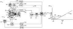
- FIG. 1schematically illustrates an aircraft 10 that includes a pair of hybrid electric propulsion systems 100 A, 100 B (also referred to as hybrid gas turbine engines 100 A, 100 B or hybrid propulsion systems 100 A, 100 B).
- Each of the hybrid electric propulsion systems 100 A, 100 Bincludes a gas turbine engine 20 with a low speed spool 30 configured to drive rotation of a fan 42 .
- Gas turbine engine 20also includes a high speed spool 32 that operates at higher speeds and pressures than the low speed spool 30 .
- a low spool motor 12 Ais configured to augment rotational power of the low speed spool 30 .
- a high spool motor 12 Bcan be configured to augment rotational power of the high speed spool 32 .
- At least one power source 16 of the aircraft 10can provide electrical power to the low spool motor 12 A and/or to the high spool motor 12 B.
- the power source 16can be a stored energy source or a generator driven by an engine.
- the power source 16can include one or more of a battery, a super capacitor, an ultra capacitor, a fuel cell, a flywheel, and the like.
- the aircraft 10includes an additional thermal engine (not depicted), such as an auxiliary power unit, the power source 16 can be a generator driven by the thermal engine.
- a generator of one of the hybrid electric propulsion systems 100 A, 100 Bcan provide power to the other hybrid electric propulsion systems 100 A, 100 B.
- the hybrid electric propulsion system 100 Bmay operate without burning fuel and can drive the low speed spool 30 based on the low spool motor 12 A receiving electric power from the hybrid electric propulsion system 100 A and/or the power source 16 .
- the high speed spool 32can be driven based on the high spool motor 12 B receiving electric power from the hybrid electric propulsion system 100 A and/or the power source 16 .
- FIG. 1illustrates a simplified example of the gas turbine engine 20
- any number of spools, and inclusion or omission of other elements and subsystemsare contemplated.
- rotor systems described hereincan be used in a variety of applications and need not be limited to gas turbine engines for aircraft applications.
- rotor systemscan be included in power generation systems, which may be ground-based as a fixed position or mobile system, and other such applications.
- FIG. 2illustrates a hybrid electric propulsion system 100 (also referred to as hybrid gas turbine engine 100 or hybrid propulsion system 100 ) as a further example of the hybrid electric propulsion system 100 A, 100 B of FIG. 1 .
- the hybrid electric propulsion system 100includes gas turbine engine 20 operably coupled to an electrical power system 210 as part of a hybrid electric aircraft, such as aircraft 10 of FIG. 1 .
- One or more mechanical power transmissions 150can be operably coupled between the gas turbine engine 20 and the electrical power system 210 .
- the gas turbine engine 20includes one or more spools, such as low speed spool 30 and high speed spool 32 , each with at least one compressor section and at least one turbine section operably coupled to a shaft (e.g., low pressure compressor 44 and low pressure turbine 46 coupled to inner shaft 40 and high pressure compressor 52 and high pressure turbine 54 coupled to outer shaft 50 ).
- the electrical power system 210can include a low spool motor 12 A configured to augment rotational power of the low speed spool 30 and a high spool motor 12 B configured to augment rotational power of the high speed spool 32 . Although two motors 12 A, 12 B are depicted in FIG.
- the electrical power system 210can also include a low spool generator 213 A configured to convert rotational power of the low speed spool 30 to electric power and a high spool generator 213 B configured to convert rotational power of the high speed spool 32 to electric power. Although two electric generators 213 A, 213 B (generally referred to as generators 213 A, 213 B) are depicted in FIG.
- one or more of the motors 12 A, 12 Bcan be configured as a motor or a generator depending upon an operational mode or system configuration, and thus one or more of the electric generators 213 A, 213 B may be omitted.
- the mechanical power transmission 150 Aincludes a gearbox operably coupled between the inner shaft 40 and a combination of the low spool motor 12 A and low spool generator 213 A.
- the mechanical power transmission 150 Bcan include a gearbox operably coupled between the outer shaft 50 and a combination of the high spool motor 12 B and high spool generator 213 B.
- the mechanical power transmission 150 A, 150 Bcan include a clutch or other interfacing element(s).
- the electrical power system 210can also include motor drive electronics 214 A, 214 B operable to condition current to the motors 12 A, 12 B (e.g., DC-to-AC converters).
- the electrical power system 210can also include rectifier electronics 215 A, 215 B operable to condition current from the electric generators 213 A, 213 B (e.g., AC-to-DC converters).
- the motor drive electronics 214 A, 214 B and rectifier electronics 215 A, 215 Bcan interface with an energy storage management system 216 that further interfaces with an energy storage system 218 .
- the energy storage management system 216can be a bi-directional DC-DC converter that regulates voltages between energy storage system 218 and electronics 214 A, 214 B, 215 A, 215 B.
- the energy storage system 218can include one or more energy storage devices, such as a battery, a super capacitor, an ultra capacitor, and the like.
- the energy storage management system 216can facilitate various power transfers within the hybrid electric propulsion system 100 .
- the energy storage management system 216may also transfer power to one or more electric motors on the engine, or to external loads 217 and receive power from one or more external power sources 219 (e.g., power source 16 of FIG. 1 , aircraft power, auxiliary power unit power, cross-engine power, and the like).
- a power conditioning unit 220 and/or other componentscan be powered by the energy storage system 218 .
- the power conditioning unit 220can distribute electric power to support actuation and other functions of the gas turbine engine 20 .
- the power conditioning unit 220can power an integrated fuel control unit 222 to control fuel flow to the gas turbine engine 20 .
- the power conditioning unit 220can also power a plurality of actuators (not depicted), such as bleed actuators, vane actuators, and the like.
- One or more accessories 70can also be driven by or otherwise interface with the gas turbine engine 20 .
- accessories 70can include oil pumps, fuel pumps, and other such components.
- the accessories 70include an oil pump driven through gearing, such as mechanical power transmission 150 B, in response to rotation of the high speed spool 32 and/or the high spool motor 12 B.
- accessories 70can be electrically driven through power provided by the energy storage management system 216 or other such sources of electrical power.
- any effectors that can change a state of the gas turbine engine 20 and/or the electrical power system 210may be referred to as hybrid electric system control effectors 240 .
- Examples of the hybrid electric system control effectors 240can include the motors 12 A, 12 B, electric generators 213 A, 213 B, integrated fuel control unit 222 , and/or other elements (not depicted).
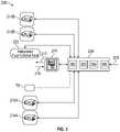
- FIG. 3is a schematic diagram of control signal paths 250 of the hybrid electric propulsion system 100 of FIG. 2 and is described with continued reference to FIGS. 1 and 2 .
- a controller 256can interface with the motor drive electronics 214 A, 214 B, rectifier electronics 215 A, 215 B, energy storage management system 216 , integrated fuel control unit 222 , accessories 70 , and/or other components (not depicted) of the hybrid electric propulsion system 100 .
- the controller 256can control and monitor for fault conditions of the gas turbine engine 20 and/or the electrical power system 210 .
- the controller 256can be integrally formed or otherwise in communication with a full authority digital engine control (FADEC) of the gas turbine engine 20 .
- FADECfull authority digital engine control
- the controller 256can be an aircraft level control or be distributed between one or more systems of the aircraft 10 of FIG. 1 .
- the controller 256can include a processing system 260 , a memory system 262 , and an input/output interface 264 .
- the controller 256can also include various operational controls, such as a hybrid engine control 266 that controls the hybrid electric system control effectors 240 further described herein, for instance, based on a thrust command 270 .
- the thrust command 270can be a throttle lever angle or a command derived based on a throttle lever angle control of the aircraft 10 of FIG. 1 .
- the processing system 260can include any type or combination of central processing unit (CPU), including one or more of: a microprocessor, a digital signal processor (DSP), a microcontroller, an application specific integrated circuit (ASIC), a field programmable gate array (FPGA), or the like.
- the memory system 262can store data and instructions that are executed by the processing system 260 .
- the memory system 262may include random access memory (RAM), read only memory (ROM), or other electronic, optical, magnetic, or any other computer readable medium onto which is stored data and algorithms in a non-transitory form.
- the input/output interface 264is configured to collect sensor data from the one or more system sensors and interface with various components and subsystems, such as components of the motor drive electronics 214 A, 214 B, rectifier electronics 215 A, 215 B, energy storage management system 216 , integrated fuel control unit 222 , accessories 70 , and/or other components (not depicted) of the hybrid electric propulsion system 100 .
- the controller 256provides a means for controlling the hybrid electric system control effectors 240 using a hybrid engine control 266 that can be dynamically updated during operation of the hybrid electric propulsion system 100 .
- the means for controlling the hybrid electric system control effectors 240can be otherwise subdivided, distributed, or combined with other control elements.
- the controller 256 with hybrid engine control 266can apply control laws and access/update models to determine how to control and transfer power between the low speed spool 30 and high speed spool 32 .
- sensed and/or derived parameters related to speed, flow rate, pressure ratios, temperature, thrust, and the likecan be used to establish operational schedules and transition limits to maintain efficient operation of the gas turbine engine 20 .
- a mode of operation of the gas turbine engine 20such as idle, takeoff, climb, cruise, and descent can have different power settings, thrust requirements, flow requirements, and temperature effects.
- the hybrid engine control 266can control electric current provided to the low spool motor 12 A and high spool motor 12 B and loading effects of the low spool generator 213 A and high spool generator 213 B.
- the hybrid engine control 266can also determine a power split between delivering fuel to the combustor 56 and using the low spool motor 12 A and/or high spool motor 12 B to power rotation within the gas turbine engine 20 .
- plot 300graphically illustrates a relationship between engine spool speeds and time when transitioning through multiple operating modes.
- Line 302indicates a percent speed 312 of the low speed spool 30 as time 310 advances and the hybrid electric propulsion system 100 transitions between e-taxi 306 , engine start 307 , and conventional idle 308 .
- E-taxi 306refers to a mode of operation where the low spool motor 12 A drives rotation of the low speed spool 30 to produce thrust using the fan 42 , such that the aircraft 10 can be maneuvered on the ground without burning fuel in the combustor 56 .
- Line 304indicates a percent speed 312 of the high speed spool 32 as time 310 advances and the hybrid electric propulsion system 100 transitions between e-taxi 306 , engine start 307 , and conventional idle 308 .
- the high speed spool 32can remain undriven during e-taxi mode 306 , which conserves energy by avoiding fuel burn and power draw from the high spool motor 12 B.
- the high spool motor 12 Bcan be used to increase the speed of the high speed spool 32 for light off and fuel burn in the combustor 56 .
- conventional idle 308the motors 12 A, 12 B may not be needed, and the gas turbine engine 20 may be power by fuel burn.
- the engine-on idle statemay include a further hybrid element where the idle state of the engine includes both fuel input and electric input to the electric motors 12 A, 12 B, or draw through the electric generators 213 A, 213 B.
- Thisis referred to as sub-idle, being possibly below conventional fuel-only idle in terms of either fuel flow and/or thrust.
- plot 400graphically illustrates a relationship between thrust 412 and throttle lever angle (TLA) 410 .
- Line 402depicts an example thrust response starting at the e-taxi mode 306 of FIG. 4 , where thrust 412 can be commanded below idle by controlling the low spool motor 12 A to drive rotation of the low speed spool 30 absent fuel burn in the combustor 56 .
- the operating mode of line 402is for fuel off and electricity available as limited by a lower operating limit 403 .
- the lower operating limit 403may be associated with a fuel-off detent of the TLA 410 .
- An idle level 407may be associated with an idle detent of the TLA 410 .
- Line 404depicts an example of a thrust response during engine start 307 of FIG. 3 , where thrust 412 can be provided below an idle level 407 using the low spool motor 12 A to control thrust 412 while also using the high spool motor 12 B to control the high speed spool 32 to provide sufficient compression in the gas turbine engine 20 for light off in the combustor 56 .
- Line 406depicts an example of a thrust response after starting the gas turbine engine 20 at idle level 407 , such as idle 308 of FIG. 4 . Controlling the low spool motor 12 A and high spool motor 12 B can support a sub-idle operation state with thrust control at power settings lower than idle level 407 .
- Thrust 12can be controlled at a demand and power output via the low spool motor 12 A and/or high spool motor 12 B for a thrust output less than a minimum thrust output at engine idle.
- the thrust response depicted at line 406can start at idle level 407 and continue up in relation to TLA 410 along a response profile 408 .
- lines 402 , 404 , 406 and response profile 408are depicted as substantially linear segments, it will be understood that lines 402 , 404 , 406 and response profile 408 can have other shapes and characteristics.
- the hybrid electric propulsion systems 100 A, 100 Bcan be independently controlled such that one of the hybrid electric propulsion systems 100 A, 100 B is operating in a fuel burning mode while the other of the hybrid electric propulsion systems 100 A, 100 B is operated using the low spool motor 12 A and/or the high spool motor 12 B or a blend of fuel burn and electric power.
- Such mixed modes of operationmay be used, for instance, during descent of the aircraft 10 , where thrust 412 is desired from both gas turbine engines 20 , but only one of the gas turbine engines 20 actively burns fuel.
- embodimentscan support e-taxi mode 306 with warmup time to delay starting of the gas turbine engines 20 until reaching a location on the taxiway away from a boarding gate.
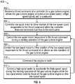
- FIG. 6is a flow chart illustrating a method 600 for providing hybrid gas turbine engine starting control, in accordance with an embodiment.
- the method 600may be performed, for example, by the hybrid electric propulsion system 100 of FIG. 2 .
- the method 600is described primarily with respect to the hybrid electric propulsion system 100 ; however, it will be understood that the method 600 can be performed on other configurations (not depicted).
- the operating statecan depend on a combination of commands, conditions, and modes, such as an e-taxi mode, a starting mode, a ground idle mode, a takeoff mode, a climb mode, a cruise mode, an in-flight idle mode, a descent mode, a landing mode, and other such modes.
- the controller 256can determine an allocation of the thrust command 270 between commanding fuel flow to the combustor 56 and electric current to the low spool motor 12 A based on the operating state of the gas turbine engine 20 and a throttle lever angle 410 , where the throttle lever angle 410 can be received from a pilot control, an auto-pilot control, or other such source on the aircraft 10 .
- the low spool motor 12 Acan be powered by one or more of a generator, an energy storage system, and a power source 16 external to the gas turbine engine 20 .
- the controller 256can control the low spool motor 12 A responsive to the thrust command 270 during a starting operation of the gas turbine engine 20 .
- the starting operationcan be a ground-based start or an in-flight restart.
- the controller 256can control the low spool motor 12 A to drive rotation of the low speed spool 30 responsive to the thrust command at or above an idle condition of the gas turbine engine 20 .
- a low spool generator 213 Ais configured to extract power from the low speed spool 30
- a high spool generator 213 Bis configured to extract power from the high speed spool 32
- the controller 256can be configured to selectively provide electrical power from the low spool generator 213 A to the high spool motor 12 B and selectively provide electrical power from the high spool generator 213 B to the low spool motor 12 A.
- the controller 256can also be configured to selectively engage either or both of the low spool generator 213 A and the high spool generator 213 B to adjust a load and speed of either or both of the low speed spool 30 and the high speed spool 32 .
Landscapes
- Engineering & Computer Science (AREA)
- Chemical & Material Sciences (AREA)
- Combustion & Propulsion (AREA)
- Mechanical Engineering (AREA)
- General Engineering & Computer Science (AREA)
- Aviation & Aerospace Engineering (AREA)
- Control Of Turbines (AREA)
Abstract
Description
Claims (16)
Priority Applications (2)
| Application Number | Priority Date | Filing Date | Title |
|---|---|---|---|
| US16/936,602US11549464B2 (en) | 2019-07-25 | 2020-07-23 | Hybrid gas turbine engine starting control |
| US18/151,652US20230160358A1 (en) | 2019-07-25 | 2023-01-09 | Hybrid gas turbine engine starting control |
Applications Claiming Priority (2)
| Application Number | Priority Date | Filing Date | Title |
|---|---|---|---|
| US201962878439P | 2019-07-25 | 2019-07-25 | |
| US16/936,602US11549464B2 (en) | 2019-07-25 | 2020-07-23 | Hybrid gas turbine engine starting control |
Related Child Applications (1)
| Application Number | Title | Priority Date | Filing Date |
|---|---|---|---|
| US18/151,652ContinuationUS20230160358A1 (en) | 2019-07-25 | 2023-01-09 | Hybrid gas turbine engine starting control |
Publications (2)
| Publication Number | Publication Date |
|---|---|
| US20210025339A1 US20210025339A1 (en) | 2021-01-28 |
| US11549464B2true US11549464B2 (en) | 2023-01-10 |
Family
ID=71894594
Family Applications (2)
| Application Number | Title | Priority Date | Filing Date |
|---|---|---|---|
| US16/936,602ActiveUS11549464B2 (en) | 2019-07-25 | 2020-07-23 | Hybrid gas turbine engine starting control |
| US18/151,652PendingUS20230160358A1 (en) | 2019-07-25 | 2023-01-09 | Hybrid gas turbine engine starting control |
Family Applications After (1)
| Application Number | Title | Priority Date | Filing Date |
|---|---|---|---|
| US18/151,652PendingUS20230160358A1 (en) | 2019-07-25 | 2023-01-09 | Hybrid gas turbine engine starting control |
Country Status (2)
| Country | Link |
|---|---|
| US (2) | US11549464B2 (en) |
| EP (1) | EP3770398B1 (en) |
Cited By (3)
| Publication number | Priority date | Publication date | Assignee | Title |
|---|---|---|---|---|
| US20230160358A1 (en)* | 2019-07-25 | 2023-05-25 | Raytheon Technologies Corporation | Hybrid gas turbine engine starting control |
| US20230184171A1 (en)* | 2021-12-14 | 2023-06-15 | Rolls-Royce Plc | Restarting a gas turbine engine |
| EP4417799A1 (en)* | 2023-02-14 | 2024-08-21 | Pratt & Whitney Canada Corp. | Sub-idle hybrid operation mode for hybrid electric propulsion system |
Families Citing this family (11)
| Publication number | Priority date | Publication date | Assignee | Title |
|---|---|---|---|---|
| US11378016B2 (en)* | 2020-08-27 | 2022-07-05 | Ampaire, Inc. | Systems and methods for determining and/or controlling motor thrust and engine thrust in a parallel hybrid aircraft |
| US20220063826A1 (en)* | 2020-08-31 | 2022-03-03 | General Electric Company | In-flight hybrid electric engine shutdown |
| US12031479B2 (en)* | 2020-08-31 | 2024-07-09 | General Electric Company | Hybrid electric propulsion system load share |
| US20220396365A1 (en)* | 2021-06-11 | 2022-12-15 | Raytheon Technologies Corporation | Hybrid electric engine power distribution |
| GB202109740D0 (en)* | 2021-07-06 | 2021-08-18 | Rolls Royce Plc | Gas turbine engine and operating method |
| US11988159B2 (en)* | 2021-07-20 | 2024-05-21 | General Electric Company | Electric machine power assist of turbine engine during idle operation |
| US20230138476A1 (en)* | 2021-10-29 | 2023-05-04 | Raytheon Technologies Corporation | Hybrid electric single engine descent restart |
| US11867131B2 (en) | 2021-10-29 | 2024-01-09 | Rtx Corporation | Hybrid electric single engine descent mode activation logic |
| US20240270399A1 (en)* | 2021-11-17 | 2024-08-15 | Verdego Aero, Inc. | Hybrid control system spanning multiple operation modes |
| US12006880B2 (en) | 2022-09-12 | 2024-06-11 | General Electric Company | High bandwidth control of turbofan/turboprop thrust response using embedded electric machines |
| FR3143556B1 (en)* | 2022-12-16 | 2024-12-13 | Safran | Method for managing power transitions between a generation mode and an assistance mode |
Citations (35)
| Publication number | Priority date | Publication date | Assignee | Title |
|---|---|---|---|---|
| US5212943A (en)* | 1991-10-08 | 1993-05-25 | Sundstrand Corporation | Reduced thermal stress turbine starting strategy |
| US20050056021A1 (en)* | 2003-09-12 | 2005-03-17 | Mes International, Inc. | Multi-spool turbogenerator system and control method |
| US20060042252A1 (en)* | 2004-08-25 | 2006-03-02 | Honeywell International, Inc. | Engine power extraction control system |
| US20060225431A1 (en)* | 2005-04-08 | 2006-10-12 | United Technologies Corporation | Electrically coupled supercharger for a gas turbine engine |
| WO2007053932A1 (en) | 2005-11-09 | 2007-05-18 | Pratt & Whitney Canada Corp. | Method and system for taxiing an aircraft |
| US7468561B2 (en)* | 2007-03-27 | 2008-12-23 | General Electric Company | Integrated electrical power extraction for aircraft engines |
| US7980509B2 (en)* | 2007-03-08 | 2011-07-19 | The Ashman Group, Llc | Aircraft taxiing systems |
| US20120000204A1 (en)* | 2010-07-02 | 2012-01-05 | Icr Turbine Engine Corporation | Multi-spool intercooled recuperated gas turbine |
| EP2452878A2 (en)* | 2010-11-16 | 2012-05-16 | Rolls-Royce Corporation | Aircraft, propulsion system, and system for taxiing an aircraft |
| US20120119020A1 (en)* | 2010-11-16 | 2012-05-17 | Donald Burns | Aircraft, propulsion system, and system for taxiing an aircraft |
| US20120317973A1 (en)* | 2011-06-14 | 2012-12-20 | General Electric Company | Asymmetrical Combined Cycle Power Plant |
| US20130031912A1 (en)* | 2011-08-01 | 2013-02-07 | Hamilton Sundstrand Corporation | Gas turbine start architecture |
| US20140084677A1 (en)* | 2011-05-20 | 2014-03-27 | Turbomeca | Method for rationalising a chain of electrical components of an aircraft, implementation architecture and corresponding aircraft |
| US8955335B2 (en) | 2010-12-30 | 2015-02-17 | Rolls-Royce Corporation | System, propulsion system and vehicle |
| EP2889452A1 (en) | 2013-12-30 | 2015-07-01 | Rolls-Royce Corporation | System and method for coordinated control of a power system |
| US9601970B2 (en) | 2013-03-13 | 2017-03-21 | Rolls-Royce North American Technologies, Inc. | Gas turbine engine and electrical system |
| US20170190441A1 (en)* | 2016-01-05 | 2017-07-06 | The Boeing Company | Aircraft engine and associated method for driving the fan with the low pressure shaft during taxi operations |
| US20170335795A1 (en)* | 2016-05-18 | 2017-11-23 | Rolls-Royce North American Technologies, Inc. | Low pressure generator for gas turbine engine |
| US20180002025A1 (en)* | 2016-07-01 | 2018-01-04 | United Technologies Corporation | Aircraft including parallel hybrid gas turbine electric propulsion system |
| US20180216526A1 (en)* | 2017-01-30 | 2018-08-02 | Ge Aviation Systems Llc | Engine Core Assistance |
| US10090676B2 (en)* | 2015-06-03 | 2018-10-02 | Northrop Grumman Systems Corporation | Aircraft DC power distribution systems and methods |
| WO2018211227A1 (en) | 2017-05-19 | 2018-11-22 | Safran | Hybrid propulsion architecture for an aircraft comprising a motor with two reversible electric machines mounted on two shafts |
| US20180354632A1 (en)* | 2017-06-12 | 2018-12-13 | General Electric Company | Propulsion system for an aircraft |
| US20190002115A1 (en) | 2017-05-17 | 2019-01-03 | General Electric Company | Hybrid-electric propulsion system for an aircraft |
| US20190001955A1 (en)* | 2017-06-30 | 2019-01-03 | General Electric Company | Propulsion system for an aircraft |
| US20190002113A1 (en) | 2017-06-30 | 2019-01-03 | General Electric Company | Propulsion system for an aircraft |
| US20190250058A1 (en)* | 2018-02-09 | 2019-08-15 | General Electric Company | Pressure Sensing Devices, Systems, and Methods for Alleviating Interference From Moisture |
| US20190375512A1 (en)* | 2018-06-08 | 2019-12-12 | Embraer S.A. | Hybrid electric taxi system (hets) or full electric taxi system (fets) |
| US10641179B2 (en)* | 2016-11-07 | 2020-05-05 | General Electric Company | System and method for starting gas turbine engines |
| US20200157966A1 (en)* | 2018-11-20 | 2020-05-21 | Ge Aviation Systems Llc | Engine assembly |
| US20200277063A1 (en)* | 2019-03-01 | 2020-09-03 | Pratt & Whitney Canada Corp. | Normal mode operation of hybrid electric propulsion systems |
| US20200292503A1 (en)* | 2019-03-14 | 2020-09-17 | General Electric Company | Acoustic inspection device and method of operation |
| US20200392924A1 (en)* | 2019-06-12 | 2020-12-17 | Rolls-Royce Plc | Varying the bypass ratio of a turbofan engine |
| US20210039802A1 (en)* | 2018-02-09 | 2021-02-11 | Safran | Hybrid propulsion for an aircraft |
| US20210054788A1 (en)* | 2019-08-23 | 2021-02-25 | United Technologies Corporation | Augmented drive of compressors via differential and multistage turbine |
Family Cites Families (7)
| Publication number | Priority date | Publication date | Assignee | Title |
|---|---|---|---|---|
| US4541237A (en)* | 1983-10-17 | 1985-09-17 | Avco Corporation | Sub-idle speed control apparatus for an airplane turbine engine |
| JP6267945B2 (en)* | 2013-11-25 | 2018-01-24 | 三菱航空機株式会社 | Aircraft engine control computer and aircraft |
| GB201321472D0 (en)* | 2013-12-05 | 2014-01-22 | Rolls Royce Plc | Control of a gas turbine engine |
| US20170008618A1 (en)* | 2014-07-26 | 2017-01-12 | Borealis Technical Limited | Optimizing ground movement in aircraft equipped with non-engine drive means |
| US10077720B2 (en)* | 2015-04-17 | 2018-09-18 | Honda Motor Co., Ltd. | Control apparatus for a gas-turbine aeroengine |
| GB201819696D0 (en)* | 2018-12-03 | 2019-01-16 | Rolls Royce Plc | Methods and apparatus for controlling at least part of a start-up or re-light process of a gas turbine engine |
| US11549464B2 (en)* | 2019-07-25 | 2023-01-10 | Raytheon Technologies Corporation | Hybrid gas turbine engine starting control |
- 2020
- 2020-07-23USUS16/936,602patent/US11549464B2/enactiveActive
- 2020-07-24EPEP20187728.9Apatent/EP3770398B1/enactiveActive
- 2023
- 2023-01-09USUS18/151,652patent/US20230160358A1/enactivePending
Patent Citations (39)
| Publication number | Priority date | Publication date | Assignee | Title |
|---|---|---|---|---|
| US5212943A (en)* | 1991-10-08 | 1993-05-25 | Sundstrand Corporation | Reduced thermal stress turbine starting strategy |
| US20050056021A1 (en)* | 2003-09-12 | 2005-03-17 | Mes International, Inc. | Multi-spool turbogenerator system and control method |
| US20060042252A1 (en)* | 2004-08-25 | 2006-03-02 | Honeywell International, Inc. | Engine power extraction control system |
| US7285871B2 (en) | 2004-08-25 | 2007-10-23 | Honeywell International, Inc. | Engine power extraction control system |
| US20060225431A1 (en)* | 2005-04-08 | 2006-10-12 | United Technologies Corporation | Electrically coupled supercharger for a gas turbine engine |
| WO2007053932A1 (en) | 2005-11-09 | 2007-05-18 | Pratt & Whitney Canada Corp. | Method and system for taxiing an aircraft |
| US7980509B2 (en)* | 2007-03-08 | 2011-07-19 | The Ashman Group, Llc | Aircraft taxiing systems |
| US7468561B2 (en)* | 2007-03-27 | 2008-12-23 | General Electric Company | Integrated electrical power extraction for aircraft engines |
| US20120000204A1 (en)* | 2010-07-02 | 2012-01-05 | Icr Turbine Engine Corporation | Multi-spool intercooled recuperated gas turbine |
| EP2452878A2 (en)* | 2010-11-16 | 2012-05-16 | Rolls-Royce Corporation | Aircraft, propulsion system, and system for taxiing an aircraft |
| US20120119020A1 (en)* | 2010-11-16 | 2012-05-17 | Donald Burns | Aircraft, propulsion system, and system for taxiing an aircraft |
| US8727270B2 (en) | 2010-11-16 | 2014-05-20 | Rolls-Royce Corporation | Aircraft, propulsion system, and system for taxiing an aircraft |
| US8955335B2 (en) | 2010-12-30 | 2015-02-17 | Rolls-Royce Corporation | System, propulsion system and vehicle |
| US20140084677A1 (en)* | 2011-05-20 | 2014-03-27 | Turbomeca | Method for rationalising a chain of electrical components of an aircraft, implementation architecture and corresponding aircraft |
| US20120317973A1 (en)* | 2011-06-14 | 2012-12-20 | General Electric Company | Asymmetrical Combined Cycle Power Plant |
| US20130031912A1 (en)* | 2011-08-01 | 2013-02-07 | Hamilton Sundstrand Corporation | Gas turbine start architecture |
| US9601970B2 (en) | 2013-03-13 | 2017-03-21 | Rolls-Royce North American Technologies, Inc. | Gas turbine engine and electrical system |
| EP2889452A1 (en) | 2013-12-30 | 2015-07-01 | Rolls-Royce Corporation | System and method for coordinated control of a power system |
| US10090676B2 (en)* | 2015-06-03 | 2018-10-02 | Northrop Grumman Systems Corporation | Aircraft DC power distribution systems and methods |
| US20170190441A1 (en)* | 2016-01-05 | 2017-07-06 | The Boeing Company | Aircraft engine and associated method for driving the fan with the low pressure shaft during taxi operations |
| EP3190052A1 (en) | 2016-01-05 | 2017-07-12 | The Boeing Company | Aircraft engine and associated method for driving the fan with the low pressure shaft during taxi operations |
| US20170335795A1 (en)* | 2016-05-18 | 2017-11-23 | Rolls-Royce North American Technologies, Inc. | Low pressure generator for gas turbine engine |
| US20180002025A1 (en)* | 2016-07-01 | 2018-01-04 | United Technologies Corporation | Aircraft including parallel hybrid gas turbine electric propulsion system |
| US10641179B2 (en)* | 2016-11-07 | 2020-05-05 | General Electric Company | System and method for starting gas turbine engines |
| US20180216526A1 (en)* | 2017-01-30 | 2018-08-02 | Ge Aviation Systems Llc | Engine Core Assistance |
| US20190002115A1 (en) | 2017-05-17 | 2019-01-03 | General Electric Company | Hybrid-electric propulsion system for an aircraft |
| WO2018211227A1 (en) | 2017-05-19 | 2018-11-22 | Safran | Hybrid propulsion architecture for an aircraft comprising a motor with two reversible electric machines mounted on two shafts |
| US20210362862A1 (en)* | 2017-05-19 | 2021-11-25 | Safran | Hybrid propulsive architecture for an aircraft comprising an engine with a reversible electric machine mounted on two shafts |
| US20180354632A1 (en)* | 2017-06-12 | 2018-12-13 | General Electric Company | Propulsion system for an aircraft |
| US20190002113A1 (en) | 2017-06-30 | 2019-01-03 | General Electric Company | Propulsion system for an aircraft |
| US20190001955A1 (en)* | 2017-06-30 | 2019-01-03 | General Electric Company | Propulsion system for an aircraft |
| US20190250058A1 (en)* | 2018-02-09 | 2019-08-15 | General Electric Company | Pressure Sensing Devices, Systems, and Methods for Alleviating Interference From Moisture |
| US20210039802A1 (en)* | 2018-02-09 | 2021-02-11 | Safran | Hybrid propulsion for an aircraft |
| US20190375512A1 (en)* | 2018-06-08 | 2019-12-12 | Embraer S.A. | Hybrid electric taxi system (hets) or full electric taxi system (fets) |
| US20200157966A1 (en)* | 2018-11-20 | 2020-05-21 | Ge Aviation Systems Llc | Engine assembly |
| US20200277063A1 (en)* | 2019-03-01 | 2020-09-03 | Pratt & Whitney Canada Corp. | Normal mode operation of hybrid electric propulsion systems |
| US20200292503A1 (en)* | 2019-03-14 | 2020-09-17 | General Electric Company | Acoustic inspection device and method of operation |
| US20200392924A1 (en)* | 2019-06-12 | 2020-12-17 | Rolls-Royce Plc | Varying the bypass ratio of a turbofan engine |
| US20210054788A1 (en)* | 2019-08-23 | 2021-02-25 | United Technologies Corporation | Augmented drive of compressors via differential and multistage turbine |
Non-Patent Citations (1)
| Title |
|---|
| EP Application No. 20187728.9 Extended EP Search Report dated Dec. 23, 2020, 6 pages. |
Cited By (5)
| Publication number | Priority date | Publication date | Assignee | Title |
|---|---|---|---|---|
| US20230160358A1 (en)* | 2019-07-25 | 2023-05-25 | Raytheon Technologies Corporation | Hybrid gas turbine engine starting control |
| US20230184171A1 (en)* | 2021-12-14 | 2023-06-15 | Rolls-Royce Plc | Restarting a gas turbine engine |
| US11905887B2 (en)* | 2021-12-14 | 2024-02-20 | Rolls-Royce Plc | Restarting a gas turbine engine |
| EP4417799A1 (en)* | 2023-02-14 | 2024-08-21 | Pratt & Whitney Canada Corp. | Sub-idle hybrid operation mode for hybrid electric propulsion system |
| US12221221B2 (en) | 2023-02-14 | 2025-02-11 | Pratt & Whitney Canada Corp. | Sub-idle hybrid operation mode for hybrid electric propulsion system |
Also Published As
| Publication number | Publication date |
|---|---|
| EP3770398A1 (en) | 2021-01-27 |
| US20230160358A1 (en) | 2023-05-25 |
| US20210025339A1 (en) | 2021-01-28 |
| EP3770398B1 (en) | 2025-03-26 |
Similar Documents
| Publication | Publication Date | Title |
|---|---|---|
| US11549464B2 (en) | Hybrid gas turbine engine starting control | |
| US11548651B2 (en) | Asymmeiric hybrid aircraft idle | |
| EP3611366B1 (en) | Hybrid gas turbine engine system powered warm-up | |
| US8979705B2 (en) | Method and system for controlling aircraft engine starter/generator | |
| US9688414B2 (en) | Intelligent integrated control system and method | |
| US12060834B2 (en) | Hybrid electric idle and braking for an aircraft | |
| RU2663786C2 (en) | Twin-engine helicopter specific fuel consumption optimization method | |
| US9611786B2 (en) | Engine systems with enhanced start control schedules | |
| CN103228872A (en) | Power generation control method applied to aircraft gas turbine and device implementing the method | |
| US12258141B2 (en) | Hybrid electric single engine descent energy management | |
| US12291995B2 (en) | Hybrid electric single engine descent power extraction control | |
| EP3772579B1 (en) | Gas turbine engine spool coupling system | |
| EP4174299B1 (en) | Hybrid electric single engine descent mode activation logic | |
| US20230138476A1 (en) | Hybrid electric single engine descent restart | |
| EP3767092B1 (en) | Modulated combustor bypass for hybrid idle | |
| JP2023047640A (en) | Propulsion system of aircraft |
Legal Events
| Date | Code | Title | Description |
|---|---|---|---|
| AS | Assignment | Owner name:RAYTHEON TECHNOLOGIES CORPORATION, CONNECTICUT Free format text:ASSIGNMENT OF ASSIGNORS INTEREST;ASSIGNORS:TERWILLIGER, NEIL;COLLOPY, GARY;SIGNING DATES FROM 20200720 TO 20200722;REEL/FRAME:053290/0270 | |
| FEPP | Fee payment procedure | Free format text:ENTITY STATUS SET TO UNDISCOUNTED (ORIGINAL EVENT CODE: BIG.); ENTITY STATUS OF PATENT OWNER: LARGE ENTITY | |
| STPP | Information on status: patent application and granting procedure in general | Free format text:DOCKETED NEW CASE - READY FOR EXAMINATION | |
| STPP | Information on status: patent application and granting procedure in general | Free format text:NON FINAL ACTION MAILED | |
| STPP | Information on status: patent application and granting procedure in general | Free format text:RESPONSE TO NON-FINAL OFFICE ACTION ENTERED AND FORWARDED TO EXAMINER | |
| STPP | Information on status: patent application and granting procedure in general | Free format text:FINAL REJECTION MAILED | |
| STPP | Information on status: patent application and granting procedure in general | Free format text:RESPONSE AFTER FINAL ACTION FORWARDED TO EXAMINER | |
| STPP | Information on status: patent application and granting procedure in general | Free format text:DOCKETED NEW CASE - READY FOR EXAMINATION | |
| STPP | Information on status: patent application and granting procedure in general | Free format text:NON FINAL ACTION MAILED | |
| STPP | Information on status: patent application and granting procedure in general | Free format text:RESPONSE TO NON-FINAL OFFICE ACTION ENTERED AND FORWARDED TO EXAMINER | |
| STPP | Information on status: patent application and granting procedure in general | Free format text:NOTICE OF ALLOWANCE MAILED -- APPLICATION RECEIVED IN OFFICE OF PUBLICATIONS | |
| STPP | Information on status: patent application and granting procedure in general | Free format text:PUBLICATIONS -- ISSUE FEE PAYMENT VERIFIED | |
| STCF | Information on status: patent grant | Free format text:PATENTED CASE | |
| AS | Assignment | Owner name:RTX CORPORATION, CONNECTICUT Free format text:CHANGE OF NAME;ASSIGNOR:RAYTHEON TECHNOLOGIES CORPORATION;REEL/FRAME:064714/0001 Effective date:20230714 |