US11549401B2 - Coal plant supplementary air and exhaust injection systems and methods of operation - Google Patents
Coal plant supplementary air and exhaust injection systems and methods of operationDownload PDFInfo
- Publication number
- US11549401B2 US11549401B2US17/303,804US202117303804AUS11549401B2US 11549401 B2US11549401 B2US 11549401B2US 202117303804 AUS202117303804 AUS 202117303804AUS 11549401 B2US11549401 B2US 11549401B2
- Authority
- US
- United States
- Prior art keywords
- coal
- air
- boiler
- fired
- steam
- Prior art date
- Legal status (The legal status is an assumption and is not a legal conclusion. Google has not performed a legal analysis and makes no representation as to the accuracy of the status listed.)
- Active
Links
Images


Classifications
- F—MECHANICAL ENGINEERING; LIGHTING; HEATING; WEAPONS; BLASTING
- F01—MACHINES OR ENGINES IN GENERAL; ENGINE PLANTS IN GENERAL; STEAM ENGINES
- F01K—STEAM ENGINE PLANTS; STEAM ACCUMULATORS; ENGINE PLANTS NOT OTHERWISE PROVIDED FOR; ENGINES USING SPECIAL WORKING FLUIDS OR CYCLES
- F01K7/00—Steam engine plants characterised by the use of specific types of engine; Plants or engines characterised by their use of special steam systems, cycles or processes; Control means specially adapted for such systems, cycles or processes; Use of withdrawn or exhaust steam for feed-water heating
- F01K7/02—Steam engine plants characterised by the use of specific types of engine; Plants or engines characterised by their use of special steam systems, cycles or processes; Control means specially adapted for such systems, cycles or processes; Use of withdrawn or exhaust steam for feed-water heating the engines being of multiple-expansion type
- F—MECHANICAL ENGINEERING; LIGHTING; HEATING; WEAPONS; BLASTING
- F01—MACHINES OR ENGINES IN GENERAL; ENGINE PLANTS IN GENERAL; STEAM ENGINES
- F01K—STEAM ENGINE PLANTS; STEAM ACCUMULATORS; ENGINE PLANTS NOT OTHERWISE PROVIDED FOR; ENGINES USING SPECIAL WORKING FLUIDS OR CYCLES
- F01K11/00—Plants characterised by the engines being structurally combined with boilers or condensers
- F01K11/02—Plants characterised by the engines being structurally combined with boilers or condensers the engines being turbines
- F—MECHANICAL ENGINEERING; LIGHTING; HEATING; WEAPONS; BLASTING
- F01—MACHINES OR ENGINES IN GENERAL; ENGINE PLANTS IN GENERAL; STEAM ENGINES
- F01K—STEAM ENGINE PLANTS; STEAM ACCUMULATORS; ENGINE PLANTS NOT OTHERWISE PROVIDED FOR; ENGINES USING SPECIAL WORKING FLUIDS OR CYCLES
- F01K23/00—Plants characterised by more than one engine delivering power external to the plant, the engines being driven by different fluids
- F01K23/02—Plants characterised by more than one engine delivering power external to the plant, the engines being driven by different fluids the engine cycles being thermally coupled
- F01K23/06—Plants characterised by more than one engine delivering power external to the plant, the engines being driven by different fluids the engine cycles being thermally coupled combustion heat from one cycle heating the fluid in another cycle
- F01K23/10—Plants characterised by more than one engine delivering power external to the plant, the engines being driven by different fluids the engine cycles being thermally coupled combustion heat from one cycle heating the fluid in another cycle with exhaust fluid of one cycle heating the fluid in another cycle
- F—MECHANICAL ENGINEERING; LIGHTING; HEATING; WEAPONS; BLASTING
- F02—COMBUSTION ENGINES; HOT-GAS OR COMBUSTION-PRODUCT ENGINE PLANTS
- F02C—GAS-TURBINE PLANTS; AIR INTAKES FOR JET-PROPULSION PLANTS; CONTROLLING FUEL SUPPLY IN AIR-BREATHING JET-PROPULSION PLANTS
- F02C3/00—Gas-turbine plants characterised by the use of combustion products as the working fluid
- F02C3/20—Gas-turbine plants characterised by the use of combustion products as the working fluid using a special fuel, oxidant, or dilution fluid to generate the combustion products
- F02C3/30—Adding water, steam or other fluids for influencing combustion, e.g. to obtain cleaner exhaust gases
- F—MECHANICAL ENGINEERING; LIGHTING; HEATING; WEAPONS; BLASTING
- F02—COMBUSTION ENGINES; HOT-GAS OR COMBUSTION-PRODUCT ENGINE PLANTS
- F02C—GAS-TURBINE PLANTS; AIR INTAKES FOR JET-PROPULSION PLANTS; CONTROLLING FUEL SUPPLY IN AIR-BREATHING JET-PROPULSION PLANTS
- F02C3/00—Gas-turbine plants characterised by the use of combustion products as the working fluid
- F02C3/34—Gas-turbine plants characterised by the use of combustion products as the working fluid with recycling of part of the working fluid, i.e. semi-closed cycles with combustion products in the closed part of the cycle
- F—MECHANICAL ENGINEERING; LIGHTING; HEATING; WEAPONS; BLASTING
- F02—COMBUSTION ENGINES; HOT-GAS OR COMBUSTION-PRODUCT ENGINE PLANTS
- F02C—GAS-TURBINE PLANTS; AIR INTAKES FOR JET-PROPULSION PLANTS; CONTROLLING FUEL SUPPLY IN AIR-BREATHING JET-PROPULSION PLANTS
- F02C6/00—Plural gas-turbine plants; Combinations of gas-turbine plants with other apparatus; Adaptations of gas-turbine plants for special use
- F02C6/14—Gas-turbine plants having means for storing energy, e.g. for meeting peak loads
- F02C6/16—Gas-turbine plants having means for storing energy, e.g. for meeting peak loads for storing compressed air
- F—MECHANICAL ENGINEERING; LIGHTING; HEATING; WEAPONS; BLASTING
- F02—COMBUSTION ENGINES; HOT-GAS OR COMBUSTION-PRODUCT ENGINE PLANTS
- F02C—GAS-TURBINE PLANTS; AIR INTAKES FOR JET-PROPULSION PLANTS; CONTROLLING FUEL SUPPLY IN AIR-BREATHING JET-PROPULSION PLANTS
- F02C9/00—Controlling gas-turbine plants; Controlling fuel supply in air- breathing jet-propulsion plants
- F02C9/48—Control of fuel supply conjointly with another control of the plant
- F02C9/50—Control of fuel supply conjointly with another control of the plant with control of working fluid flow
- F02C9/52—Control of fuel supply conjointly with another control of the plant with control of working fluid flow by bleeding or by-passing the working fluid
- F—MECHANICAL ENGINEERING; LIGHTING; HEATING; WEAPONS; BLASTING
- F22—STEAM GENERATION
- F22B—METHODS OF STEAM GENERATION; STEAM BOILERS
- F22B37/00—Component parts or details of steam boilers
- F22B37/02—Component parts or details of steam boilers applicable to more than one kind or type of steam boiler
- F22B37/48—Devices or arrangements for removing water, minerals or sludge from boilers ; Arrangement of cleaning apparatus in boilers; Combinations thereof with boilers
- Y—GENERAL TAGGING OF NEW TECHNOLOGICAL DEVELOPMENTS; GENERAL TAGGING OF CROSS-SECTIONAL TECHNOLOGIES SPANNING OVER SEVERAL SECTIONS OF THE IPC; TECHNICAL SUBJECTS COVERED BY FORMER USPC CROSS-REFERENCE ART COLLECTIONS [XRACs] AND DIGESTS
- Y02—TECHNOLOGIES OR APPLICATIONS FOR MITIGATION OR ADAPTATION AGAINST CLIMATE CHANGE
- Y02E—REDUCTION OF GREENHOUSE GAS [GHG] EMISSIONS, RELATED TO ENERGY GENERATION, TRANSMISSION OR DISTRIBUTION
- Y02E60/00—Enabling technologies; Technologies with a potential or indirect contribution to GHG emissions mitigation
- Y02E60/16—Mechanical energy storage, e.g. flywheels or pressurised fluids
Definitions
- the inventionrelates generally to electrical power systems, including generating capacity of a coal plant, and more specifically to improving the existing coal plant's capacity while at the same time improving overall plant efficiency and reducing specific emissions.
- coal plantshave significant parasitic loads that are used to drive the air from the atmosphere through the combustion chamber of the boiler as well as soot blowers to keep the boiler walls and steam pipes clean.
- These systemsuse electrical power generated from the coal plant to drive the electric motors that run the main air blowers and soot blower air compressor.
- the main air bloweris a low pressure compressor, providing less than 5 psi, and the soot blower typically operates at a much higher pressure, 125-150 psi.
- the main air bloweris typically a single stage fan and the soot blower is a multi-stage integrally-geared turbo compressor.
- the main air blowerdelivers all of the air to the combustion chamber of the coal-fired boiler at about the same temperature as the ambient conditions. Because the pressure increase across the main air blower is very low, the temperature rise is extremely small, less than one degree Fahrenheit.
- the soot blowerdelivers air to a variety of places and is used keep boiler walls and tubes clean.
- This airis generated with a multi-stage intercooled compressor which delivers high pressure air at about 200-250 deg. F.
- the airis directed to the different areas of the boiler combustion chamber to keep it clean and ultimately is part of the combustion process.
- coalis a much less expensive fuel than diesel or natural gas. For example in some countries, coal costs between $2 and $3 per MBTU, where natural gas and diesel is approximately $15/MMBTU. Therefore, coal is used for base load power while the more expensive fuels, such as diesel and natural gas, are used for peaking power.
- Stable electrical gridsrequire approximately 1-2% spinning reserve, also referred to as extra generating capacity, and for coal-fired plants, this is accomplished primarily by running the coal plants at 98-99% load, leaving the remaining 1-2% available in the event additional power is needed on the grid quickly.
- batterieshave been installed at some coal plants to provide the 1-2% spinning reserve power, thus allowing the coal plant to operate at 100% load. By doing this, effectively the grid can get an additional 1-2% more power on the grid from the coal plants before having to start more expensive fuel power generation systems, like a peaking gas turbine which can have a heat rate of 11,000 BTU/kWh.
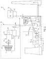
- FIG. 1shows a typical coal plant of the prior art.
- a steam turbinewhich can consist of a high pressure turbine 1 , an intermediate pressure turbine 2 , and a low pressure turbine 3 which are typically arranged to have the same shaft line as the generator 4 that they are driving.
- High pressure steam 5is generated in the boiler section 17 of the coal plant and feeds the high pressure turbine 1 , which drops the pressure and temperature of the steam.
- This intermediate pressure steam 6travels back to the boiler section 17 of the coal plant where the temperature is increased.
- the reheated intermediate pressure steam 7travels back to intermediate pressure turbine 2 , where the steam pressure and temperature is dropped as the steam powers intermediate pressure turbine 2 .
- the low pressure steam 8exits the intermediate pressure turbine 2 and enters the low pressure turbine 3 , where the remainder of energy is extracted from the steam.
- the three stages of turbinesdrive the generator 4 producing electric power delivered to the grid.
- the steam leaving the low pressure turbine 3is saturated steam and the cooling tower 25 cools this stream completely to the liquid phase and then returned to the process via a duct 9 to start the cycle over again.
- this processrequires delivering coal 13 to the plant, where the coal is ground up into fine particles and enters a mixer 12 that mixes the coal particles with air 11 .
- the mixtureis pumped into the plant with an electric or steam driven main air blower 28 .
- the mixed coal and air 10is injected into the combustion zone of the boiler 17 where the mixture is burned producing hot gasses and ash.
- the hot gassesheat water in the boiler 17 to generate steam.
- the ashis typically directed to a collector 14 and a conveyor system continuously removes the ash. However, some of the ash collects on the walls of the boiler 17 as well as the steam pipes.
- electrical driven soot blowers 18produce pressurized warm air 54 at approximately 150-200 psi and approximately 225 deg. F.
- Some systemsuse intermediate steam instead of air for the soot blower.
- the pressurized air or steamis injected with nozzles at several locations inside the boiler to keep the walls and pipes free of ash to maximize heat transfer to the steam pipes. Ignition sources keep the flame lit and the hot gasses move up through the combustion zone where they are in fluid contact with the high pressure steam pipes 31 , then the intermediate pressure steam pipes 32 , and then the gas exhausts 15 out of the coal plant.
- the current inventionprovides a system and method to use a fuel driven blower to deliver the main combustion air to the coal boiler combustion process as well as the high pressure air to the soot blower system.
- a coal-fired energy systemcomprising a coal-fired steam generator having a coal feed system and a main air feed system for producing heat to a boiler for producing steam, one or more steam turbines in fluid communication with the steam generator, piping for passing the steam between the steam generator and the one or more steam turbines, and an auxiliary air compression system providing compressed air for a soot blower of the coal-fired steam generator and waste heat to a combustion zone of the coal-fired steam generator.
- a method of operating a coal-fired energy systemcomprising operating a coal fired steam generator comprising a coal feed system and a main air feed system to provide a coal-air mixture as a heating source for a boiler for generating steam.
- An auxiliary air compression systemis also operated comprising a fueled engine coupled to a compressor for providing an auxiliary supply of compressed air to a soot blower of the coal-fired steam generator, and the supply of compressed air is injected along walls of the boiler to remove soot and ash buildup from the boiler.
- a coal-fired energy systemcomprising a coal-fired steam generator having a coal feed system and a main air feed system for producing heat to a boiler for producing steam.
- the systemalso comprises one or more steam turbines in fluid communication with the steam generator, piping for passing the steam between the steam generator and the one or more steam turbines, and, an auxiliary air compression system capable of providing compressed air for a soot blower of the coal-fired steam generator and comprising a compressor selectively driven by an electric motor or a fueled engine.
- a method of operating a coal-fired energy systemcomprising operating a coal fired steam generator comprising a coal feed system and a main air feed system to provide a coal-air mixture as a heating source for a boiler for generating steam and operating an auxiliary air compression system comprising a compressor for providing an auxiliary supply of compressed air to a soot blower of the coal-fired steam generator, where the compressor is selectively coupled to a fueled engine or an electric motor. Then, the supply of compressed air is injected along walls of the boiler to remove soot and ash buildup from the boiler.
- One aspect of the present inventionrelates to methods of producing main combustion air using an alternately fueled engine to drive the process that results in less specific emissions and increased plant output.
- Another aspect of the present inventionrelates to a method for producing air for a soot blower using an alternately fueled engine resulting in lower emissions and increased plant output.
- Another aspect of the present inventionprovides a method of preheating the soot blower air prior to injecting the air into the coal boiler, resulting in an increased output from the plant.
- Another aspect of the present inventionprovides a method of dispensing of the waste heat from an alternately fueled engine to increase the power output of the coal plant.
- auxiliary systemsincluding the primary air and/or the soot blowing system to be able to run on a separately fueled system such that the auxiliary load can be transmitted to the grid to provide spinning reserve.
- a method of operating a coal fired energy systemcomprises operating a coal fired steam generator comprising a coal feed system and a main air feed system to provide a coal-air mixture as a heating source for a boiler for generating steam.
- the methodincludes operating an auxiliary air compression system comprising a fueled engine coupled to a compressor for providing an auxiliary supply of compressed air to a soot blower of the coal-fired steam generator.
- the methodcomprises injecting the auxiliary supply of compressed air along walls of the boiler to remove soot and ash buildup from the boiler.
- the methodincludes injecting the auxiliary supply of compressed air in boiler to remove soot and ash buildup from the boiler.
- a coal-fired energy systemcomprises a coal-fired steam generator having a coal feed system and a main air feed system for producing heat to a boiler for producing steam.
- the systemincludes one or more steam turbines in fluid communication with the steam generator.
- the systemcomprises piping for passing the steam between the steam generator and the one or more steam turbines.
- the systemincludes an auxiliary air compression system capable of providing compressed air for a soot blower of the coal-fired steam generator and waste heat to a combustion zone of the coal-fired steam generator.
- FIG. 1is a schematic drawing of a typical coal plant of the prior art.
- FIG. 2is a schematic drawing of a typical coal plant incorporating an embodiment of the present invention.
- FIG. 3is a schematic drawing of a typical coal plant incorporating an alternate embodiment of the present invention.
- the present inventionrelates to systems and methods of generating the main combustion air for a coal boiler, as well as the soot blower air with an alternately fueled engine, such as a natural gas reciprocating engine. Because of the emission concerns of coal plants, there is significant pressure to reduce emissions and improve efficiency of existing coal plants. Also, because of this pressure, many coal plants are being demolished and replaced with natural gas fired combustion gas turbines.
- the main air blower and soot blowerdraws a parasitic load of about 5% of the coal plant output.
- the current inventionprovides an alternate, more efficient way of providing lower emissions by generating the pressurized air for the soot blower and the main combustion air at the coal plant.
- an embodiment of the present inventioncomprises a coal-fired energy system 200 having a coal-fired steam generator with a coal feed system 202 and a main air feed system 204 , together producing heat for the boiler 17 which in turn produces steam.
- the coal feed system 202provides a pulverized coal to a mixer 12 where it mixes with air from the main air feed system 204 . This mixture of coal and air 10 is injected into the combustion zone of the boiler 17 where it is burned and used to heat the boiler 17 .
- the main air feed system 204comprises a main air blower 208 that is powered by a fueled engine 210 .
- the fueled enginealso generates waste heat 212 that is directed towards the combustion zone of the coal boiler 33 .
- the coal energy system 200also comprises one or more steam turbines in fluid communication with the steam generator.
- the one or more steam turbinescomprise a high pressure turbine 1 , an intermediate pressure turbine 2 , and a low pressure turbine 3 .
- the present inventionalso comprises piping 206 for passing the steam between the steam generator and the one or more turbines. More specifically, the piping 206 includes a conduit for passing high pressure steam 5 to the high pressure turbine 1 , a conduit for returning steam at an intermediate pressure 6 to the boiler 17 for reheating, and a conduit for directing the reheated intermediate pressure steam 7 from the boiler to the intermediate pressure turbine 2 .
- the piping 206also includes a conduit for supplying low pressure steam from the intermediate pressure turbine 2 to the low pressure turbine 3 .
- the present inventionalso comprises an auxiliary air compression system 222 .
- the auxiliary air compression system 222comprises a fueled engine 151 that drives a multi-stage intercooled compressor 116 which takes in ambient air 115 and discharges warm compressed air 117 .
- the fueled engine 151which can operate on natural gas, biofuel, off-gas, or another non-coal fuel source, takes in ambient air 150 and fuel 124 and delivers the power to drive the intercooled compressor 116 and discharges hot exhaust 152 which goes through a recuperator 155 where it heats the warm compressed air 117 to generate hot compressed air 118 .
- the air injection valve 111is open, the hot compressed air can flow from the recuperator 155 through the soot blower air injection piping 154 and to the boiler 17 .
- a fuel-driven main air blower 208utilizes a fueled engine 210 to drive the blower 208 .
- the exhaust 212 of this fueled engine 210is joined with the exhaust 153 of the power augmentation system 222 and is routed to the combustion zone of the coal boiler 33 .
- a method of operating a coal fired energy systemis provided.
- a coal-fired steam generatoris operated, where the steam generator comprises a coal feed system and a main air feed system working together to provide a coal-air mixture as a heating source for a boiler for generating steam.
- An auxiliary air compression systemis operated to produce a supply of compressed air to a soot blower. The compressed air is then injected along walls of the boiler to remove soot and ash buildup from the boiler.
- a coal-fired energy system 300is provided as an alternate system to the coal-fired energy system 200 of FIG. 2 , and includes significant differences.
- the coal-fired energy system 300comprises a coal-fired steam generator having a coal feed system 302 and a main air feed system 304 for producing a coal-air mixture to use as fuel for boiler 17 .
- this embodimentalso includes one or more steam turbines 1 , 2 , and 3 , in fluid communication with the steam generator and piping for passing the steam between the steam generator and the one or more steam turbines.
- the coal-fired energy system 300comprises an auxiliary air compression system 322 capable of providing compressed air 354 to a soot blower, where the compressed air is produced by way of a multi-stage intercooled compressor 116 , where the compressor is selectively driven by an electric motor 351 or a fueled engine 361 .
- the compressor 116is coupled to the electric motor 351 and the fueled engine 361 by clutches 371 and 372 , respectively. Since the primary driver for this type of arrangement is spinning reserve, the electric motor is the primary driver and the diesel engine is the backup driver. When extra spinning reserve is required from the plant, the diesel engine 361 is started and takes over the power required to drive the compressor 116 , and therefore the compressor load is delivered to the grid.
- the fueled engine 361can be powered with natural gas, biofuel, off-gas or another non-coal fuel source and produces shaft power to drive the compressor 116 and engine exhaust 352 is vented to the atmosphere.
- a method of operating a coal fired energy systemis provided.
- a coal-fired steam generatoris operated, where the steam generator comprises a coal feed system and a main air feed system working together to provide a coal-air mixture as a heating source for a boiler for generating steam.
- An auxiliary air compression systemis operated to produce a supply of compressed air to a soot blower, where the compressor is selectively coupled to a fueled engine or an electric motor. The compressed air is then injected along walls of the boiler to remove soot and ash buildup from the boiler.
- coal plant systemsthat are typically electrically driven with electric motors can be dual driven with diesel engines and electric motors to provide more spinning reserve power.
- Another good example of thisis the primary air blower 328 , which can be run with both an electric motor and a diesel engine in the same fashion to provide additional spinning reserve power to the grid.
- Other examplesinclude ash handling and other conveying equipment at the plant.
Landscapes
- Engineering & Computer Science (AREA)
- Chemical & Material Sciences (AREA)
- Combustion & Propulsion (AREA)
- Mechanical Engineering (AREA)
- General Engineering & Computer Science (AREA)
- Physics & Mathematics (AREA)
- Life Sciences & Earth Sciences (AREA)
- Sustainable Development (AREA)
- Fluid Mechanics (AREA)
- Thermal Sciences (AREA)
- Engine Equipment That Uses Special Cycles (AREA)
Abstract
Description
Claims (14)
Priority Applications (1)
| Application Number | Priority Date | Filing Date | Title |
|---|---|---|---|
| US17/303,804US11549401B2 (en) | 2016-03-23 | 2021-06-08 | Coal plant supplementary air and exhaust injection systems and methods of operation |
Applications Claiming Priority (4)
| Application Number | Priority Date | Filing Date | Title |
|---|---|---|---|
| US201662312046P | 2016-03-23 | 2016-03-23 | |
| PCT/US2017/023734WO2017165598A1 (en) | 2016-03-23 | 2017-03-23 | Coal plant supplementary air and exhaust injection systems and methods of operation |
| US201816087897A | 2018-09-24 | 2018-09-24 | |
| US17/303,804US11549401B2 (en) | 2016-03-23 | 2021-06-08 | Coal plant supplementary air and exhaust injection systems and methods of operation |
Related Parent Applications (2)
| Application Number | Title | Priority Date | Filing Date |
|---|---|---|---|
| US16/087,897DivisionUS11028733B2 (en) | 2016-03-23 | 2017-03-23 | Coal plant supplementary air and exhaust injection systems and methods of operation |
| PCT/US2017/023734DivisionWO2017165598A1 (en) | 2016-03-23 | 2017-03-23 | Coal plant supplementary air and exhaust injection systems and methods of operation |
Publications (2)
| Publication Number | Publication Date |
|---|---|
| US20210293155A1 US20210293155A1 (en) | 2021-09-23 |
| US11549401B2true US11549401B2 (en) | 2023-01-10 |
Family
ID=59900841
Family Applications (2)
| Application Number | Title | Priority Date | Filing Date |
|---|---|---|---|
| US16/087,897Active2037-12-26US11028733B2 (en) | 2016-03-23 | 2017-03-23 | Coal plant supplementary air and exhaust injection systems and methods of operation |
| US17/303,804ActiveUS11549401B2 (en) | 2016-03-23 | 2021-06-08 | Coal plant supplementary air and exhaust injection systems and methods of operation |
Family Applications Before (1)
| Application Number | Title | Priority Date | Filing Date |
|---|---|---|---|
| US16/087,897Active2037-12-26US11028733B2 (en) | 2016-03-23 | 2017-03-23 | Coal plant supplementary air and exhaust injection systems and methods of operation |
Country Status (2)
| Country | Link |
|---|---|
| US (2) | US11028733B2 (en) |
| WO (1) | WO2017165598A1 (en) |
Citations (20)
| Publication number | Priority date | Publication date | Assignee | Title |
|---|---|---|---|---|
| US3151250A (en) | 1962-12-26 | 1964-09-29 | Gen Electric | Spinning reserve peaking gas turbine |
| US4347706A (en) | 1981-01-07 | 1982-09-07 | The United States Of America As Represented By The United States Department Of Energy | Electric power generating plant having direct coupled steam and compressed air cycles |
| US4441028A (en)* | 1977-06-16 | 1984-04-03 | Lundberg Robert M | Apparatus and method for multiplying the output of a generating unit |
| US4488516A (en)* | 1983-11-18 | 1984-12-18 | Combustion Engineering, Inc. | Soot blower system |
| US4630436A (en)* | 1984-07-30 | 1986-12-23 | Bbc Brown, Boveri & Company, Limited | Air storage gas turbine power station with fluidized bed firing |
| US5297959A (en) | 1990-05-07 | 1994-03-29 | Indugas, Inc. | High temperature furnace |
| US5740673A (en)* | 1995-11-07 | 1998-04-21 | Air Products And Chemicals, Inc. | Operation of integrated gasification combined cycle power generation systems at part load |
| US6035628A (en) | 1997-02-26 | 2000-03-14 | Foster Wheeler Energia Oy | Pressurized fluidized bed combustion system including control of temperature of flue gases entering a high temperature filter |
| US6750557B2 (en) | 2001-09-06 | 2004-06-15 | Energy Transfer Group, L.L.C. | Redundant prime mover system |
| US6892679B2 (en) | 2002-07-09 | 2005-05-17 | Clyde Bergemann, Inc. | Multi-media rotating sootblower and automatic industrial boiler cleaning system |
| US6912451B2 (en)* | 2001-09-06 | 2005-06-28 | Energy Transfer Group, Llc | Control system for a redundant prime mover system |
| JP2007192417A (en) | 2006-01-17 | 2007-08-02 | Nippon Steel Corp | Soot blower and method for controlling soot blower |
| US7360508B2 (en)* | 2004-06-14 | 2008-04-22 | Diamond Power International, Inc. | Detonation / deflagration sootblower |
| US7507381B2 (en) | 2002-11-05 | 2009-03-24 | Babcock-Hitachi Kabushiki Kaisha | Exhaust gas treating apparatus |
| US20120137877A1 (en) | 2010-12-02 | 2012-06-07 | Bert Zauderer | Fossil fuel fired, closed cycle mhd generator in parallel with steam turbine cycle with zero emissions and co2 sequestration |
| US20140041358A1 (en)* | 2011-07-14 | 2014-02-13 | Yasunari Shibata | Gas cooler, gasification furnace, and integrated gasification combined cycle for carbon-containing fuel |
| US20140250902A1 (en) | 2012-04-02 | 2014-09-11 | Robert J. Kraft | Compressed air injection system method and apparatus for gas turbine engines |
| US20150107498A1 (en)* | 2013-10-18 | 2015-04-23 | Fuel Tech, Inc. | Controlling Injection of Magnesium Oxide for Controlling SO3 with Enhanced Bioler Efficiency |
| US9476582B2 (en)* | 2009-12-11 | 2016-10-25 | Power & Control Solutions, Inc. | System and method for removing slag inside a utility furnace |
| US20170211900A1 (en) | 2014-10-20 | 2017-07-27 | Mitsubishi Hitachi Power Systems, Ltd. | Heat exchanger monitoring device and heat exchanger monitoring method |
- 2017
- 2017-03-23USUS16/087,897patent/US11028733B2/enactiveActive
- 2017-03-23WOPCT/US2017/023734patent/WO2017165598A1/ennot_activeCeased
- 2021
- 2021-06-08USUS17/303,804patent/US11549401B2/enactiveActive
Patent Citations (20)
| Publication number | Priority date | Publication date | Assignee | Title |
|---|---|---|---|---|
| US3151250A (en) | 1962-12-26 | 1964-09-29 | Gen Electric | Spinning reserve peaking gas turbine |
| US4441028A (en)* | 1977-06-16 | 1984-04-03 | Lundberg Robert M | Apparatus and method for multiplying the output of a generating unit |
| US4347706A (en) | 1981-01-07 | 1982-09-07 | The United States Of America As Represented By The United States Department Of Energy | Electric power generating plant having direct coupled steam and compressed air cycles |
| US4488516A (en)* | 1983-11-18 | 1984-12-18 | Combustion Engineering, Inc. | Soot blower system |
| US4630436A (en)* | 1984-07-30 | 1986-12-23 | Bbc Brown, Boveri & Company, Limited | Air storage gas turbine power station with fluidized bed firing |
| US5297959A (en) | 1990-05-07 | 1994-03-29 | Indugas, Inc. | High temperature furnace |
| US5740673A (en)* | 1995-11-07 | 1998-04-21 | Air Products And Chemicals, Inc. | Operation of integrated gasification combined cycle power generation systems at part load |
| US6035628A (en) | 1997-02-26 | 2000-03-14 | Foster Wheeler Energia Oy | Pressurized fluidized bed combustion system including control of temperature of flue gases entering a high temperature filter |
| US6912451B2 (en)* | 2001-09-06 | 2005-06-28 | Energy Transfer Group, Llc | Control system for a redundant prime mover system |
| US6750557B2 (en) | 2001-09-06 | 2004-06-15 | Energy Transfer Group, L.L.C. | Redundant prime mover system |
| US6892679B2 (en) | 2002-07-09 | 2005-05-17 | Clyde Bergemann, Inc. | Multi-media rotating sootblower and automatic industrial boiler cleaning system |
| US7507381B2 (en) | 2002-11-05 | 2009-03-24 | Babcock-Hitachi Kabushiki Kaisha | Exhaust gas treating apparatus |
| US7360508B2 (en)* | 2004-06-14 | 2008-04-22 | Diamond Power International, Inc. | Detonation / deflagration sootblower |
| JP2007192417A (en) | 2006-01-17 | 2007-08-02 | Nippon Steel Corp | Soot blower and method for controlling soot blower |
| US9476582B2 (en)* | 2009-12-11 | 2016-10-25 | Power & Control Solutions, Inc. | System and method for removing slag inside a utility furnace |
| US20120137877A1 (en) | 2010-12-02 | 2012-06-07 | Bert Zauderer | Fossil fuel fired, closed cycle mhd generator in parallel with steam turbine cycle with zero emissions and co2 sequestration |
| US20140041358A1 (en)* | 2011-07-14 | 2014-02-13 | Yasunari Shibata | Gas cooler, gasification furnace, and integrated gasification combined cycle for carbon-containing fuel |
| US20140250902A1 (en) | 2012-04-02 | 2014-09-11 | Robert J. Kraft | Compressed air injection system method and apparatus for gas turbine engines |
| US20150107498A1 (en)* | 2013-10-18 | 2015-04-23 | Fuel Tech, Inc. | Controlling Injection of Magnesium Oxide for Controlling SO3 with Enhanced Bioler Efficiency |
| US20170211900A1 (en) | 2014-10-20 | 2017-07-27 | Mitsubishi Hitachi Power Systems, Ltd. | Heat exchanger monitoring device and heat exchanger monitoring method |
Non-Patent Citations (1)
| Title |
|---|
| International Search Report and Written Opinion, dated Jun. 7, 2017, 11 pages, issued in PCT Application No. PCT/US2017/023734. |
Also Published As
| Publication number | Publication date |
|---|---|
| US20210293155A1 (en) | 2021-09-23 |
| US20200300127A1 (en) | 2020-09-24 |
| US11028733B2 (en) | 2021-06-08 |
| WO2017165598A1 (en) | 2017-09-28 |
Similar Documents
| Publication | Publication Date | Title |
|---|---|---|
| US4831817A (en) | Combined gas-steam-turbine power plant | |
| JP4245678B2 (en) | How to operate a combined cycle plant | |
| CA1332516C (en) | Plant for the generation of mechanical energy, and process for the operation of such a plant | |
| CN101484675B (en) | Indirect-fired gas turbine power plant | |
| US10480418B2 (en) | Gas turbine energy supplementing systems and heating systems, and methods of making and using the same | |
| US20130125525A1 (en) | Gas turbine power plant with a gas turbine installation, and method for operating a gas turbine power plant | |
| CN104769256A (en) | Gas turbine energy supplement system and heating system | |
| CN101517213A (en) | Gas turbine | |
| EP3314166A1 (en) | Method and equipment for combustion of ammonia | |
| JPH10184315A (en) | Gas turbine generator | |
| ES336944A1 (en) | Power plant with steam injection | |
| US11022040B2 (en) | Backup system for supplying compressed air to a gas turbine component | |
| US5525053A (en) | Method of operating a combined cycle power plant | |
| US5906094A (en) | Partial oxidation power plants and methods thereof | |
| US11549401B2 (en) | Coal plant supplementary air and exhaust injection systems and methods of operation | |
| CN103244270A (en) | Steam injection assembly for a combined cycle system | |
| US20060225428A1 (en) | Dual fuel combined cycle power plant | |
| US8640437B1 (en) | Mini sized combined cycle power plant | |
| CN103644003A (en) | Combined-cycle thermal power generation device with general fuel | |
| CN107166383A (en) | A kind of oxygen-enriched few-oil ignition system of boiler | |
| Takano et al. | Design for the 145-MW blast furnace gas firing gas turbine combined cycle plant | |
| RU124080U1 (en) | ELECTRICITY GENERATION DEVICE | |
| CN216950580U (en) | Internal and external mixed combustion engine with combustion nozzle | |
| RU2327890C1 (en) | Locomotive power gas turbine plant | |
| RU2349777C1 (en) | Power plant of gas turbine locomotive with heat recovery |
Legal Events
| Date | Code | Title | Description |
|---|---|---|---|
| AS | Assignment | Owner name:POWERPHASE LLC, FLORIDA Free format text:ASSIGNMENT OF ASSIGNORS INTEREST;ASSIGNOR:KRAFT, ROBERT J.;REEL/FRAME:056470/0933 Effective date:20170323 | |
| FEPP | Fee payment procedure | Free format text:ENTITY STATUS SET TO UNDISCOUNTED (ORIGINAL EVENT CODE: BIG.); ENTITY STATUS OF PATENT OWNER: SMALL ENTITY | |
| AS | Assignment | Owner name:POWERPHASE INTERNATIONAL, LLC, FLORIDA Free format text:ASSIGNMENT OF ASSIGNORS INTEREST;ASSIGNOR:POWERPHASE LLC;REEL/FRAME:056490/0065 Effective date:20201218 | |
| FEPP | Fee payment procedure | Free format text:ENTITY STATUS SET TO SMALL (ORIGINAL EVENT CODE: SMAL); ENTITY STATUS OF PATENT OWNER: SMALL ENTITY | |
| STPP | Information on status: patent application and granting procedure in general | Free format text:DOCKETED NEW CASE - READY FOR EXAMINATION | |
| STPP | Information on status: patent application and granting procedure in general | Free format text:NON FINAL ACTION MAILED | |
| STPP | Information on status: patent application and granting procedure in general | Free format text:NOTICE OF ALLOWANCE MAILED -- APPLICATION RECEIVED IN OFFICE OF PUBLICATIONS | |
| STPP | Information on status: patent application and granting procedure in general | Free format text:NOTICE OF ALLOWANCE MAILED -- APPLICATION RECEIVED IN OFFICE OF PUBLICATIONS | |
| STPP | Information on status: patent application and granting procedure in general | Free format text:PUBLICATIONS -- ISSUE FEE PAYMENT VERIFIED | |
| STCF | Information on status: patent grant | Free format text:PATENTED CASE |