US11548650B2 - Hybrid airship - Google Patents
Hybrid airshipDownload PDFInfo
- Publication number
- US11548650B2 US11548650B2US15/530,528US201715530528AUS11548650B2US 11548650 B2US11548650 B2US 11548650B2US 201715530528 AUS201715530528 AUS 201715530528AUS 11548650 B2US11548650 B2US 11548650B2
- Authority
- US
- United States
- Prior art keywords
- generator
- airship
- electric motors
- multicopter
- recited
- Prior art date
- Legal status (The legal status is an assumption and is not a legal conclusion. Google has not performed a legal analysis and makes no representation as to the accuracy of the status listed.)
- Active, expires
Links
- 238000002485combustion reactionMethods0.000claimsabstractdescription17
- 230000033001locomotionEffects0.000claimsdescription7
- 230000005611electricityEffects0.000claimsdescription6
- 230000009467reductionEffects0.000claimsdescription3
- 239000007789gasSubstances0.000abstractdescription27
- 238000005516engineering processMethods0.000abstractdescription9
- 239000001307heliumSubstances0.000abstractdescription6
- 229910052734heliumInorganic materials0.000abstractdescription6
- SWQJXJOGLNCZEY-UHFFFAOYSA-Nhelium atomChemical compound[He]SWQJXJOGLNCZEY-UHFFFAOYSA-N0.000abstractdescription6
- UFHFLCQGNIYNRP-UHFFFAOYSA-NHydrogenChemical compound[H][H]UFHFLCQGNIYNRP-UHFFFAOYSA-N0.000abstractdescription3
- 239000001257hydrogenSubstances0.000abstractdescription3
- 229910052739hydrogenInorganic materials0.000abstractdescription3
- 239000000446fuelSubstances0.000description8
- 230000008901benefitEffects0.000description5
- 239000003350keroseneSubstances0.000description3
- 239000000463materialSubstances0.000description3
- 230000004044responseEffects0.000description3
- 238000006243chemical reactionMethods0.000description2
- 238000010586diagramMethods0.000description2
- 230000000694effectsEffects0.000description2
- 239000002828fuel tankSubstances0.000description2
- 238000000034methodMethods0.000description2
- 238000012986modificationMethods0.000description2
- 230000004048modificationEffects0.000description2
- 238000012544monitoring processMethods0.000description2
- 239000004033plasticSubstances0.000description2
- 230000002441reversible effectEffects0.000description2
- 229920000049Carbon (fiber)Polymers0.000description1
- 230000005540biological transmissionEffects0.000description1
- 239000004917carbon fiberSubstances0.000description1
- 230000008859changeEffects0.000description1
- 238000013480data collectionMethods0.000description1
- 230000009977dual effectEffects0.000description1
- 230000002349favourable effectEffects0.000description1
- 230000005484gravityEffects0.000description1
- 238000007689inspectionMethods0.000description1
- 238000005259measurementMethods0.000description1
- 239000002184metalSubstances0.000description1
- VNWKTOKETHGBQD-UHFFFAOYSA-NmethaneChemical compoundCVNWKTOKETHGBQD-UHFFFAOYSA-N0.000description1
- 230000007935neutral effectEffects0.000description1
- 230000002085persistent effectEffects0.000description1
Images


Classifications
- B—PERFORMING OPERATIONS; TRANSPORTING
- B64—AIRCRAFT; AVIATION; COSMONAUTICS
- B64D—EQUIPMENT FOR FITTING IN OR TO AIRCRAFT; FLIGHT SUITS; PARACHUTES; ARRANGEMENT OR MOUNTING OF POWER PLANTS OR PROPULSION TRANSMISSIONS IN AIRCRAFT
- B64D27/00—Arrangement or mounting of power plants in aircraft; Aircraft characterised by the type or position of power plants
- B64D27/02—Aircraft characterised by the type or position of power plants
- B64D27/24—Aircraft characterised by the type or position of power plants using steam or spring force
- B—PERFORMING OPERATIONS; TRANSPORTING
- B64—AIRCRAFT; AVIATION; COSMONAUTICS
- B64B—LIGHTER-THAN AIR AIRCRAFT
- B64B1/00—Lighter-than-air aircraft
- B64B1/06—Rigid airships; Semi-rigid airships
- B64B1/24—Arrangement of propulsion plant
- B64B1/30—Arrangement of propellers
- B64B1/32—Arrangement of propellers surrounding hull
- B—PERFORMING OPERATIONS; TRANSPORTING
- B64—AIRCRAFT; AVIATION; COSMONAUTICS
- B64B—LIGHTER-THAN AIR AIRCRAFT
- B64B1/00—Lighter-than-air aircraft
- B64B1/06—Rigid airships; Semi-rigid airships
- B64B1/24—Arrangement of propulsion plant
- B64B1/30—Arrangement of propellers
- B64B1/34—Arrangement of propellers of lifting propellers
- B—PERFORMING OPERATIONS; TRANSPORTING
- B64—AIRCRAFT; AVIATION; COSMONAUTICS
- B64C—AEROPLANES; HELICOPTERS
- B64C39/00—Aircraft not otherwise provided for
- B64C39/02—Aircraft not otherwise provided for characterised by special use
- B64C39/024—Aircraft not otherwise provided for characterised by special use of the remote controlled vehicle type, i.e. RPV
- B—PERFORMING OPERATIONS; TRANSPORTING
- B64—AIRCRAFT; AVIATION; COSMONAUTICS
- B64D—EQUIPMENT FOR FITTING IN OR TO AIRCRAFT; FLIGHT SUITS; PARACHUTES; ARRANGEMENT OR MOUNTING OF POWER PLANTS OR PROPULSION TRANSMISSIONS IN AIRCRAFT
- B64D27/00—Arrangement or mounting of power plants in aircraft; Aircraft characterised by the type or position of power plants
- B64D27/02—Aircraft characterised by the type or position of power plants
- B64D27/30—Aircraft characterised by electric power plants
- B64D27/35—Arrangements for on-board electric energy production, distribution, recovery or storage
- B64D27/357—Arrangements for on-board electric energy production, distribution, recovery or storage using batteries
- B—PERFORMING OPERATIONS; TRANSPORTING
- B64—AIRCRAFT; AVIATION; COSMONAUTICS
- B64D—EQUIPMENT FOR FITTING IN OR TO AIRCRAFT; FLIGHT SUITS; PARACHUTES; ARRANGEMENT OR MOUNTING OF POWER PLANTS OR PROPULSION TRANSMISSIONS IN AIRCRAFT
- B64D31/00—Power plant control systems; Arrangement of power plant control systems in aircraft
- B64D31/16—Power plant control systems; Arrangement of power plant control systems in aircraft for electric power plants
- B64D31/18—Power plant control systems; Arrangement of power plant control systems in aircraft for electric power plants for hybrid-electric power plants
- B—PERFORMING OPERATIONS; TRANSPORTING
- B64—AIRCRAFT; AVIATION; COSMONAUTICS
- B64D—EQUIPMENT FOR FITTING IN OR TO AIRCRAFT; FLIGHT SUITS; PARACHUTES; ARRANGEMENT OR MOUNTING OF POWER PLANTS OR PROPULSION TRANSMISSIONS IN AIRCRAFT
- B64D35/00—Transmitting power from power plants to propellers or rotors; Arrangements of transmissions
- B64D35/02—Transmitting power from power plants to propellers or rotors; Arrangements of transmissions specially adapted for specific power plants
- B64D35/021—Transmitting power from power plants to propellers or rotors; Arrangements of transmissions specially adapted for specific power plants for electric power plants
- B64D35/022—Transmitting power from power plants to propellers or rotors; Arrangements of transmissions specially adapted for specific power plants for electric power plants of hybrid-electric type
- B64D35/024—Transmitting power from power plants to propellers or rotors; Arrangements of transmissions specially adapted for specific power plants for electric power plants of hybrid-electric type of series type
- B—PERFORMING OPERATIONS; TRANSPORTING
- B64—AIRCRAFT; AVIATION; COSMONAUTICS
- B64D—EQUIPMENT FOR FITTING IN OR TO AIRCRAFT; FLIGHT SUITS; PARACHUTES; ARRANGEMENT OR MOUNTING OF POWER PLANTS OR PROPULSION TRANSMISSIONS IN AIRCRAFT
- B64D35/00—Transmitting power from power plants to propellers or rotors; Arrangements of transmissions
- B64D35/02—Transmitting power from power plants to propellers or rotors; Arrangements of transmissions specially adapted for specific power plants
- B64D35/021—Transmitting power from power plants to propellers or rotors; Arrangements of transmissions specially adapted for specific power plants for electric power plants
- B64D35/026—Transmitting power from power plants to propellers or rotors; Arrangements of transmissions specially adapted for specific power plants for electric power plants the electric power plant being integral with the propeller or rotor
- B—PERFORMING OPERATIONS; TRANSPORTING
- B64—AIRCRAFT; AVIATION; COSMONAUTICS
- B64U—UNMANNED AERIAL VEHICLES [UAV]; EQUIPMENT THEREFOR
- B64U10/00—Type of UAV
- B64U10/10—Rotorcrafts
- B64U10/13—Flying platforms
- B—PERFORMING OPERATIONS; TRANSPORTING
- B64—AIRCRAFT; AVIATION; COSMONAUTICS
- B64U—UNMANNED AERIAL VEHICLES [UAV]; EQUIPMENT THEREFOR
- B64U10/00—Type of UAV
- B64U10/30—Lighter-than-air aircraft, e.g. aerostatic aircraft
- B—PERFORMING OPERATIONS; TRANSPORTING
- B64—AIRCRAFT; AVIATION; COSMONAUTICS
- B64U—UNMANNED AERIAL VEHICLES [UAV]; EQUIPMENT THEREFOR
- B64U30/00—Means for producing lift; Empennages; Arrangements thereof
- B64U30/20—Rotors; Rotor supports
- B—PERFORMING OPERATIONS; TRANSPORTING
- B64—AIRCRAFT; AVIATION; COSMONAUTICS
- B64U—UNMANNED AERIAL VEHICLES [UAV]; EQUIPMENT THEREFOR
- B64U50/00—Propulsion; Power supply
- B64U50/10—Propulsion
- B64U50/11—Propulsion using internal combustion piston engines
- B—PERFORMING OPERATIONS; TRANSPORTING
- B64—AIRCRAFT; AVIATION; COSMONAUTICS
- B64U—UNMANNED AERIAL VEHICLES [UAV]; EQUIPMENT THEREFOR
- B64U50/00—Propulsion; Power supply
- B64U50/10—Propulsion
- B64U50/13—Propulsion using external fans or propellers
- B—PERFORMING OPERATIONS; TRANSPORTING
- B64—AIRCRAFT; AVIATION; COSMONAUTICS
- B64U—UNMANNED AERIAL VEHICLES [UAV]; EQUIPMENT THEREFOR
- B64U50/00—Propulsion; Power supply
- B64U50/10—Propulsion
- B64U50/19—Propulsion using electrically powered motors
- B—PERFORMING OPERATIONS; TRANSPORTING
- B64—AIRCRAFT; AVIATION; COSMONAUTICS
- B64B—LIGHTER-THAN AIR AIRCRAFT
- B64B2201/00—Hybrid airships, i.e. airships where lift is generated aerodynamically and statically
- B64C2201/022—
- B64C2201/027—
- B64C2201/042—
- B64C2201/101—
- B64C2201/108—
- B64C2201/162—
- B64C2201/165—
- B64D2027/026—
- B—PERFORMING OPERATIONS; TRANSPORTING
- B64—AIRCRAFT; AVIATION; COSMONAUTICS
- B64D—EQUIPMENT FOR FITTING IN OR TO AIRCRAFT; FLIGHT SUITS; PARACHUTES; ARRANGEMENT OR MOUNTING OF POWER PLANTS OR PROPULSION TRANSMISSIONS IN AIRCRAFT
- B64D2221/00—Electric power distribution systems onboard aircraft
- B—PERFORMING OPERATIONS; TRANSPORTING
- B64—AIRCRAFT; AVIATION; COSMONAUTICS
- B64D—EQUIPMENT FOR FITTING IN OR TO AIRCRAFT; FLIGHT SUITS; PARACHUTES; ARRANGEMENT OR MOUNTING OF POWER PLANTS OR PROPULSION TRANSMISSIONS IN AIRCRAFT
- B64D27/00—Arrangement or mounting of power plants in aircraft; Aircraft characterised by the type or position of power plants
- B64D27/02—Aircraft characterised by the type or position of power plants
- B64D27/026—Aircraft characterised by the type or position of power plants comprising different types of power plants, e.g. combination of a piston engine and a gas-turbine
- B—PERFORMING OPERATIONS; TRANSPORTING
- B64—AIRCRAFT; AVIATION; COSMONAUTICS
- B64U—UNMANNED AERIAL VEHICLES [UAV]; EQUIPMENT THEREFOR
- B64U10/00—Type of UAV
- B64U10/10—Rotorcrafts
- B64U10/13—Flying platforms
- B64U10/14—Flying platforms with four distinct rotor axes, e.g. quadcopters
- B—PERFORMING OPERATIONS; TRANSPORTING
- B64—AIRCRAFT; AVIATION; COSMONAUTICS
- B64U—UNMANNED AERIAL VEHICLES [UAV]; EQUIPMENT THEREFOR
- B64U2201/00—UAVs characterised by their flight controls
- B64U2201/20—Remote controls
- B—PERFORMING OPERATIONS; TRANSPORTING
- B64—AIRCRAFT; AVIATION; COSMONAUTICS
- B64U—UNMANNED AERIAL VEHICLES [UAV]; EQUIPMENT THEREFOR
- B64U30/00—Means for producing lift; Empennages; Arrangements thereof
- B64U30/20—Rotors; Rotor supports
- B64U30/26—Ducted or shrouded rotors
- B—PERFORMING OPERATIONS; TRANSPORTING
- B64—AIRCRAFT; AVIATION; COSMONAUTICS
- B64U—UNMANNED AERIAL VEHICLES [UAV]; EQUIPMENT THEREFOR
- B64U50/00—Propulsion; Power supply
- B64U50/10—Propulsion
- B64U50/13—Propulsion using external fans or propellers
- B64U50/14—Propulsion using external fans or propellers ducted or shrouded
- Y—GENERAL TAGGING OF NEW TECHNOLOGICAL DEVELOPMENTS; GENERAL TAGGING OF CROSS-SECTIONAL TECHNOLOGIES SPANNING OVER SEVERAL SECTIONS OF THE IPC; TECHNICAL SUBJECTS COVERED BY FORMER USPC CROSS-REFERENCE ART COLLECTIONS [XRACs] AND DIGESTS
- Y02—TECHNOLOGIES OR APPLICATIONS FOR MITIGATION OR ADAPTATION AGAINST CLIMATE CHANGE
- Y02T—CLIMATE CHANGE MITIGATION TECHNOLOGIES RELATED TO TRANSPORTATION
- Y02T50/00—Aeronautics or air transport
- Y02T50/40—Weight reduction
- Y—GENERAL TAGGING OF NEW TECHNOLOGICAL DEVELOPMENTS; GENERAL TAGGING OF CROSS-SECTIONAL TECHNOLOGIES SPANNING OVER SEVERAL SECTIONS OF THE IPC; TECHNICAL SUBJECTS COVERED BY FORMER USPC CROSS-REFERENCE ART COLLECTIONS [XRACs] AND DIGESTS
- Y02—TECHNOLOGIES OR APPLICATIONS FOR MITIGATION OR ADAPTATION AGAINST CLIMATE CHANGE
- Y02T—CLIMATE CHANGE MITIGATION TECHNOLOGIES RELATED TO TRANSPORTATION
- Y02T50/00—Aeronautics or air transport
- Y02T50/60—Efficient propulsion technologies, e.g. for aircraft
Definitions
- the inventionrelates to a hybrid airship (drone, UAV) which is capable of significantly extended flight times. This can be accomplished in two different ways, or the two may be combined together to provide even longer flight times.
- the first technologyuses a combination of a lifting gas (such as hydrogen or helium) and multirotor technology for lift and maneuvering.
- the second technologyequips the airship (drone, UAV) with an on board generator to charge the batteries during flight for extended flight operations, with an internal combustion engine driving the generator.
- a quadcopterin the first technology, includes an ellipsoid shaped volume or “balloon” for retaining the lifting gas in the center thereof.
- the balloonmay be made of any suitable material as long as it is lightweight and capable of containing helium or the like.
- the lighter-than-air gas contained within the ellipsoid balloonprovides the majority of the lift while four (or more) motors/propellers use standard quadcopter methodology (powered by one or more batteries, as is conventional) to provide additional lift and to maneuver, including to facilitate descent. This is fundamentally different than a conventional airship or dirigible because in those scenarios none of the lift is intended to be provided by the propulsion system.
- the airshipis equipped with an on board generator, and a powered device for driving the generator such as an internal combustion engine, to provide power to charge the batteries.
- a powered device for driving the generatorsuch as an internal combustion engine
- An electronic controller boarduses a series of microprocessors, complex hardware, software, programming, and gyros to keep the craft flying.
- the electronic controllerwhich is central to all of these machines maintains flight through changes in RPM and torque of the motors to maintain flight.
- Electric motorsrespond fast enough to allow the microprocessor to do the job of keeping the machine in flight.
- Combustion enginesare not able to respond fast enough to the demands of the flight controller to fly with any precision.
- an enginee. g. gas turbine
- a preferred internal combustion engine to power one or more generatorsis a gas turbine engine with a high power to weight ratio. Such an engine will desirably run at about the rpm necessary to power the one or more generators.
- the most preferred commercial engine for one embodiment of the inventionweighs only about five pounds yet is capable of producing about 9 kW of power—or is scaled up with comparable values for larger craft [with a power to weight ratio, in kW and pounds, of at least 1:1, preferably at least about 1.5:1 and desirably about 1.8-2.0:1 or more].
- Such a deviceis capable of extending the air time of a conventional multicopter to at least one-two hours.
- the generatormay be a single ac or dc generator or may comprise multiple small ac or dc generators configured in series so that one or perhaps up to four generators may be brought on line electronically (by the controller) as necessary.
- an airshipcomprising: a frame; a plurality of rotors operatively mounted to the frame driven by a plurality of electric motors for providing both lift and horizontal movement of the airship; at least one battery operatively connected to the electric motors to provide electricity for powering the electric motors; an electronic controller for controlling the motors; and a flight time-extending device distinct from the battery, rotors and electric motors.
- the flight time-extending deviceincludes a central volume of lighter-than-air gas.
- the central volume (or balloon)is preferably generally ellipsoid in shape, and the airship may comprise a quadcopter.
- the airship framemay comprise circumferential bands for mounting the rotors to the ellipsoid central volume.
- the airshipmay also further comprise a plurality of laterally oriented thrusters.
- the flight time-extending devicecomprises: at least one generator for recharging the at least one battery; and an internal combustion engine with a high power to weight ratio for powering the at least one generator.
- the internal combustion enginesuch as a gas turbine engine, preferably has a power to weight ratio, expressed in kW and pounds, of at least about 1.5:1, and more desirably about 1.8:1 or more.
- the at least one generatormay comprise a generator for each electric motor.
- the central volume of lighter than air gas, as described above,may also be provided.
- a multicoptere. g. quadcopter
- the multicoptermay comprise: a frame; a plurality of rotors driven by a plurality of electric motors for providing both lift and horizontal movement of the airship frame; at least one battery operatively connected to the electric motors to provide electricity for powering the electric motors; an electronic controller for controlling the electric motors; at least one generator for recharging the at least one battery; and an internal combustion engine with a high power to weight ratio for powering the at least one generator.
- the internal combustion enginewhich may be a gas turbine engine, has a power to weight ratio, expressed in kW and pounds, of at least about 1.5:1, e. g. about 1.8:1.
- the at least one generatormay comprise a generator for each electric motor.
- a multicoptere. g. quadcopter
- a multicoptercomprising: a frame; a plurality of rotors driven by a plurality of electric motors for providing both lift and horizontal movement of the airship frame; at least one battery operatively connected to the electric motors to provide electricity for powering the electric motors; an electronic controller for controlling the electric motors; and a central volume of lighter-than-air gas.
- the central volumeis preferably generally ellipsoid in shape.
- the framemay comprise circumferential bands for mounting the rotors to the ellipsoid central volume.
- a plurality of laterally oriented thrustersmay also be provided.
- FIG. 1is a top isometric view of a first exemplary embodiment of a multicopter according to the invention with a lighter than air gas volume for extending flight time;
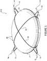
- FIG. 2is a view like that of FIG. 1 with additional structure in the form of laterally oriented thrusters;
- FIG. 3is a schematic view of the bottom of the multicopter of FIG. 1 schematically showing a battery and electronic controller mounted to the frame of the UAV;
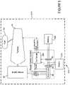
- FIG. 4is block diagram schematically illustrating a second exemplary embodiment of a multicopter according to the invention with a gas turbine engine and generator for extending flight time;
- FIGS. 5 - 7are block diagrams generally like that of FIG. 4 only showing modifications of the components thereof.
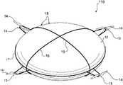
- FIG. 1illustrates a quadcopter 10 with an ellipsoid shaped volume (or “balloon”) 12 for retaining the lifting gas in the center thereof.
- the balloon 12may be made of any suitable material as long as it is lightweight and capable of containing helium or the like, such as reinforced gas-tight plastic, or materials that airships like dirigibles are typically made of.
- the lighter-than-air gas such as hydrogen or helium (not shown and not visible in any event) contained within the ellipsoid balloon 12provides the majority of the lift while the four conventional electric motors 13 driving the conventional propellers 14 (preferably evenly spaced around the periphery of the ellipsoid balloon 12 ) use standard quadcopter methodology (powered by at least one battery 25 , as is conventional, and as seen in FIG. 3 ) to provide additional lift and to maneuver, including to facilitate descent. This is fundamentally different than a conventional airship or dirigible because in those scenarios none of the lift is intended to be provided by the propulsion system.
- standard quadcopter methodologypowered by at least one battery 25 , as is conventional, and as seen in FIG. 3
- the electric motors/propellers 13 , 14are preferably held in place on the generally ellipsoid-shaped balloon 12 by circumferential metal, carbon-fiber, plastic, or the like bands 15 , 16 , and 17 , which comprise part of the frame—shown generally by reference numeral 18 in FIGS. 1 - 3 —of the quadcopter 10 .
- the purpose of the preferred ellipsoid shape of the central volume 12is to minimize the aerodynamic profile from the side to reduce the effect of wind and drag during translational motion. Shapes with a flattened bottom for the central volume 12 may also be used so that the additional lift is provided if there is airflow over and around the airship 10 , such as during lateral motion or in the presence of wind.
- the quadcopter 10is capable of a greater payload capacity than a conventional quadcopter (or multicopter) because of the additional lift provided by the lifting-gas within ellipsoid 12 .
- Another benefitis that compared to a standard multicopter, the flight time is significantly greater, due to the fact that most of the time battery energy is only consumed by the motors/rotors 13 , 14 during maneuvering and not for lifting. That is the lifting volume 12 comprises a flight time-extending device distinct from the rotors 14 and electric motors 13 (and battery 25 —see FIG. 3 ).
- volume 12While an ellipsoid shape of the volume 12 is preferred, it can be any shape that would conveniently allow the maneuvering motors/propellers 13 , 14 to be mounted to the craft 10 and have relatively low aerodynamic drag. That is, balloon 12 could be generally spherical, cushion-shaped, or donut-shaped, etc. Also while four electric motors/propellers 13 , 14 are illustrated in the drawings as few as three or as many as eight (or even more) may be provided, preferably spaced approximately equally around the circumference of the balloon 12 .
- the amount of lifting gas in balloon 12 usedcan be varied to produce more or less lift as the situation requires. Sometimes more buoyancy will be desired for example in light wind conditions. More buoyancy will provide longer battery life but may not be desirable in stronger wind conditions. Basically airship 10 could be a lighter than air craft or a neutral buoyancy craft depending on the conditions the craft 10 is being flown in.
- FIG. 2shows a multicopter 110 that is the same as the quadcopter 10 of FIG. 1 with additional structures, with the same structures as in FIG. 1 shown by the same reference numerals.
- the multicopter 110includes lifting gas in the central ellipsoid balloon 12 and additionally, employs laterally oriented thrusters shown by reference numeral 20 .
- Shrouds 21 for the propellers 22 of the thrusters 20are illustrated in FIG. 2 for clarity, but the multicopter 110 may or may not utilize the following features for providing thrust on all rotors:
- the UAV 110does not need to pitch or roll the entire craft in order to move horizontally. This maintains a lower drag profile and allows a much quicker response, since the time required to pitch and roll is eliminated. This ability to quickly generate lateral thrusts allows the drone 110 to rapidly compensate for gusts of wind and potentially maintain a very precise position or trajectory, otherwise difficult to achieve with traditional multirotor designs. If more or positive buoyancy is used the reversible thrust motors 20 can be used to force a descent rather than maintain altitude.
- Both of the airships 10 , 110provide significant increases in safety and reliability compared to conventional multicopters.
- the redundancy of the dual systems which provide lift (lifting gas and multirotor)mean that either one can fail without catastrophic results. Should the lifting gas escape ellipsoid 12 for any reason, the airship 10 , 110 is still capable of flying and landing like a standard multicopter. Should the motors 13 or the rotors 14 fail, the lifting gas and large surface area of ellipsoid 12 prevent airship 10 , 110 from descending too rapidly.
- the low average density of the airships 10 , 110means that a collision will be significantly less severe than with or for a traditional multicopter of equivalent payload capacity.
- the four (could be any number) horizontally directed rotors 20 shown in FIG. 2provide additional redundancy, meaning that even if some rotors fail it is still possible to maneuver safely.
- One example of such a scenariois if all four of the downwards facing rotors 14 failed, the vehicle 110 could orient itself on its side and provide lift with the two now-downwards facing shrouded propellers 20 .
- an ellipsoid 12 volume of the shape pictured in FIGS. 1 & 2could lift:
- This payload capacityis more than sufficient for practical purposes to carry durable frame and propulsion systems ( 14 - 18 , 20 , 25 , and 26 ) while still leaving enough remaining payload capacity for a wide variety of equipment and other payloads which may be attached to the airships 10 , 110 to the bottom thereof (preferably to frame 18 ), to a structure on the top, or in any other way known in the trade.
- FIG. 3schematically illustrates at least one battery 25 and a conventional electronic controller 26 for controlling the motors 13 in response to signals received from a ground or aircraft operator, mounted to the frame 18 .
- Such structures 25 , 26could be mounted at any conventional location on the multicopter 10 , 110 , preferably near the horizontal center of gravity thereof, with a view to making sure that the UAV 10 , 110 is basically balanced.
- Potential applications for the airships 10 , 110include:
- FIGS. 4 - 7illustrate another embodiment of an airship or multicopter 210 according to the invention with a different type of flight time-extending device which can be used in addition to, or (as illustrated in FIGS. 4 - 7 ) instead of, the central volume 12 .
- elements comparable to those in the FIGS. 1 - 3 embodimentare shown by the same two digit reference numeral preceded by a “2.”
- the standard components of a multicopter 210including a frame 218 , conventional electric motors 213 for driving conventional propellers 214 , at least one conventional battery 225 , and a conventional electronic controller 226 for controlling the motors 213 in response to control signals from the ground or aircraft, are illustrated.
- the flight time-extending devicecomprises one or more generators 30 operatively connected to the electronic controller 226 for charging the at least one battery 225 , and an internal combustion engine 32 with a high power to weight ratio for powering the at least one generator 30 .
- the internal combustion engine 32has a power to weight ratio, expressed in kW and pounds, of at least 1:1, preferably at least about 1.5:1, and desirably about 1.8-2.0:1 or more.
- the engine 32may be selected from a wide variety of conventional or to be developed internal combustion engines.
- Preferred for smaller drones 210is a 5-10 kW turbo shaft gas turbine engine 32 which runs on jet fuel or kerosene from fuel tank 34 .
- the turbine engine 32will provide enough power to the generator 30 to keep the battery 225 charged to extend flight times to approximately 2 hours as one of the biggest problems that the invention seeks to solve is the power capacity and weight of conventional multicopter batteries.
- Jet Central Turbines enginewhich is a single stage centrifugal flow gas turbine engine configured to operate as a turbojet engine. It has a kerosene start, an intelligent control system, a fuel pump, electronic starting gas vale, and electronic fuel vale, weighs only about five pounds and produces about 9 kW of power so that its power to weight ratio (expressed in kW and pounds) is about 1.8:1.
- the gas-turbine engine 32consumes fuel from kerosene or jet fuel tank 34 and generates mechanical energy.
- the preferred Jet Central turbine 32has a gear reduction system which provides an output RPM in the range of about 6000 to 8000 RPM.
- the electromechanical generator 30is directly mechanically coupled to the output shaft of the turbine 32 and also rotates at about 6000 to 8000 RPM. This range of RPM allows commonly available, light-weight, electric motors with high power density to be used as the electric generator 30 . The voltage-constant of such commonly available motors acting as generator 30 will result in an output voltage that is suitable for charging the battery 225 of a UAV 210 .
- the electronic controller (power control system) 226is connected to the electrical output of the generator 30 and is electrically connected to the battery 225 .
- the power control system 226provides the electrical power output of the entire power plant.
- a task of the power control system 226is to maintain the battery 225 in a fully-charged state.
- the power control system 226can control the desired RPM of the gas-turbine engine 32 , and can control the electrical load that it puts on the generator 30 .
- the power control system 226monitors the power draw from the electric load (e. g. motors 213 ) on the system, the voltage of the battery 225 , and the power provided by the generator 30 . Based on the information from monitoring these, it controls the electrical load on the generator 30 and the desired RPM of the turbine 32 to keep the battery 225 substantially fully charged.
- the electric loade. g. motors 213
- an external data input to the power control system 226may also be used.
- the external data inputgives an estimate of the expected power draw from the power plant.
- the power control system 226provides a data output which contains information on the activity of the power control system 226 . This includes things such estimates on the state of charge of the battery 225 , the power draw from the electrical load, and the power being provided by the generator 30 .
- FIGS. 5 - 7show other embodiments similar to those of FIG. 4 , all having the same reference numerals (if they exist) as in FIG. 4 .
- a brushless direct current (BLDC) motorshown in the FIG. 5 embodiment
- a brushed direct current motorshown in FIG. 6
- a conventional charge controller 36suited to the choice of electromechanical generator 30 must be used.
- the charge controller 36controls how much electrical energy is harvested from the electromechanical generator 30 based on control input from the power controller 226 .
- the power controller 226determines how much load is placed on the electromechanical generator 30 through the charge controller 36 based on measurements received from two power meters 38 , 39 .
- the power controller 226increases the load on the electromechanical generator 30 through the charge controller 36 if the energy in the battery 225 falls below a threshold value.
- multiple smaller motors/generators 30 and charge controllers 36can be used in place of single units in order to provide redundancy, distribute electrical loads, and simplify the control of power draw.
- Using a system such as in FIGS. 4 - 7allows the size of the battery/batteries 225 to be reduced while the UAV 210 operates properly. In some cases a battery 225 that is small enough to only act as an energy buffer for scenarios where there are sudden high power draws is all that is necessary.
- the absolute best energy density of batteriesis 160 Wh/kg.
- the system of FIGS. 4 - 7may be said to have an energy density of 150 Wh/kg [that is with 17.6 kg of fuel—enough for one hour usage at full power according to the specifications for the preferred turbine 32 ]. After burning half of the fuel, the weight is reduced to approximately 9 kg; then the energy density is 211 Wh/kg. This is an advantage over using batteries, because the weight of batteries doesn't decrease as their energy is consumed.
- the airships according to the inventioncan be made any size, including large enough to carry a human being or other payload on the order of about 60-120 kg. While it is preferred that the airship according to the invention be controlled by signals from the ground or another flying device, if the airship according to the invention carried a human, the human himself/herself may control the airship using conventional human controls.
Landscapes
- Engineering & Computer Science (AREA)
- Aviation & Aerospace Engineering (AREA)
- Mechanical Engineering (AREA)
- Chemical & Material Sciences (AREA)
- Combustion & Propulsion (AREA)
- Remote Sensing (AREA)
- Electric Propulsion And Braking For Vehicles (AREA)
- Connection Of Motors, Electrical Generators, Mechanical Devices, And The Like (AREA)
- Toys (AREA)
Abstract
Description
- Ducted fans
- Turbines
- Propeller shrouds
- Unshrouded propellers
- Variable pitch propellers (for reversing and the direction of thrust and rapidly modulating the amount of thrust)
- Fixed pitch propellers but used with motors which can reverse direction and change speed
| 1 m | ~0.23 kg | ||
| 2 m | ~1.8 kg | ||
| 3 m | ~6.3 kg | ||
| 4 m | ~15 kg | ||
| 5 m | ~29 kg | ||
- Persistent, long endurance surveillance and data collection
- Arena sports video coverage
- Remote wildlife monitoring
- Proximity inspection of difficult to access structures and objects (radio towers, power transmission lines, oil pipelines)
- Search and rescue
- Wireless data service provision (cellphone and internet coverage)
Claims (11)
Priority Applications (2)
| Application Number | Priority Date | Filing Date | Title |
|---|---|---|---|
| US15/530,528US11548650B2 (en) | 2016-02-05 | 2017-01-25 | Hybrid airship |
| PCT/US2017/000039WO2018139982A1 (en) | 2016-02-05 | 2017-07-19 | Hybrid airship |
Applications Claiming Priority (2)
| Application Number | Priority Date | Filing Date | Title |
|---|---|---|---|
| US201662388724P | 2016-02-05 | 2016-02-05 | |
| US15/530,528US11548650B2 (en) | 2016-02-05 | 2017-01-25 | Hybrid airship |
Publications (2)
| Publication Number | Publication Date |
|---|---|
| US20180022461A1 US20180022461A1 (en) | 2018-01-25 |
| US11548650B2true US11548650B2 (en) | 2023-01-10 |
Family
ID=60990501
Family Applications (1)
| Application Number | Title | Priority Date | Filing Date |
|---|---|---|---|
| US15/530,528Active2038-12-12US11548650B2 (en) | 2016-02-05 | 2017-01-25 | Hybrid airship |
Country Status (2)
| Country | Link |
|---|---|
| US (1) | US11548650B2 (en) |
| WO (1) | WO2018139982A1 (en) |
Families Citing this family (27)
| Publication number | Priority date | Publication date | Assignee | Title |
|---|---|---|---|---|
| JP6601701B2 (en)* | 2016-03-10 | 2019-11-06 | パナソニックIpマネジメント株式会社 | Flying object |
| EP3529145B1 (en)* | 2016-10-24 | 2021-12-08 | Sceye Sa | Airship construction and method for producing the same where a harness-structure is fastened around a hull. |
| RU2734559C2 (en)* | 2017-03-07 | 2020-10-20 | Александр Александрович Перфилов | Aerospace electric train |
| US11299249B2 (en)* | 2017-10-19 | 2022-04-12 | Daniel Wibbing | Propulsion system for highly maneuverable airship |
| CN108146608B (en)* | 2017-12-19 | 2020-11-24 | 北京航空航天大学 | A composite aerostat with vector thrust rotor and inflatable airbag |
| US10611242B2 (en)* | 2017-12-21 | 2020-04-07 | Loon Llc | Managing power of aerial vehicles |
| EP3517428B1 (en)* | 2018-01-26 | 2021-10-06 | AIRBUS HELICOPTERS DEUTSCHLAND GmbH | A shrouding for interacting with at least one rotor assembly |
| RU2752039C2 (en)* | 2018-03-30 | 2021-07-22 | Александр Александрович Перфилов | Hybrid aeronautical vehicle |
| RU2752038C2 (en)* | 2018-05-18 | 2021-07-22 | Александр Александрович Перфилов | Rescue aeronautical vehicle |
| USD904967S1 (en)* | 2018-08-29 | 2020-12-15 | Kaiser Enterprises, Llc | Aircraft |
| USD884553S1 (en)* | 2018-10-25 | 2020-05-19 | WAVE3D Co., Ltd | Drone |
| JP7315158B2 (en)* | 2018-11-13 | 2023-07-26 | オリエンタル白石株式会社 | Structure inspection system and flying robot |
| RU2709083C1 (en)* | 2018-12-19 | 2019-12-13 | Федеральное государственное бюджетное учреждение науки Институт проблем управления им. В.А. Трапезникова Российской академии наук | Tethered copter |
| RU194695U1 (en)* | 2019-01-23 | 2019-12-19 | Юрий Степанович Бойко | ELECTRIC DIRECTOR |
| CN109941433B (en)* | 2019-03-12 | 2020-12-11 | 嘉兴觅特电子商务有限公司 | An unmanned aerial vehicle with emergency landing function for maritime patrol |
| FR3095090B1 (en)* | 2019-04-11 | 2023-11-03 | Safran | Method and device for controlling the hybridization of an aircraft |
| US11560226B2 (en)* | 2019-05-07 | 2023-01-24 | George Miller | Drone airstation method and system |
| US11465728B2 (en) | 2019-05-30 | 2022-10-11 | Pliant Energy System LLC | Aerial swimmer apparatuses, methods and systems |
| CN110979669B (en)* | 2019-11-22 | 2021-06-01 | 武汉理工大学 | A variable saucer-shaped airship UAV |
| CN112373691A (en)* | 2020-09-03 | 2021-02-19 | 红河学院 | Use indoor unmanned aerial vehicle of helium gasbag |
| FR3118001B1 (en)* | 2020-12-18 | 2024-05-10 | Flying Whales | Electric distributed propulsion system for aircraft with hovering capabilities and aircraft equipped with such a system |
| CN113277059B (en)* | 2021-04-20 | 2023-10-27 | 浙江易飞空域技术有限公司 | Hybrid power airship composed of gas turbine and hydrogen fuel cell and operation method |
| WO2023002133A1 (en)* | 2021-07-21 | 2023-01-26 | Flying Whales | Electrically propelled airship having a rigid structure and power-generating nacelle with which said airship is provided |
| CN114148502A (en)* | 2021-12-03 | 2022-03-08 | 中国特种飞行器研究所 | Four-rotor aircraft based on floating platform |
| US12145712B2 (en)* | 2022-05-12 | 2024-11-19 | Herns Louis | High-altitude wind turbine aircraft system and method of use |
| US12151807B1 (en) | 2024-05-22 | 2024-11-26 | Dronexus Aero Llc | Manned and unmanned aircraft |
| US12269570B1 (en)* | 2024-11-12 | 2025-04-08 | James C. Wang | Navigating aircraft in a jetstream |
Citations (19)
| Publication number | Priority date | Publication date | Assignee | Title |
|---|---|---|---|---|
| US4786008A (en) | 1986-04-24 | 1988-11-22 | Grumman Aerospace Corporation | Nuclear powered drone |
| US4995572A (en)* | 1989-06-05 | 1991-02-26 | Piasecki Aircraft Corporation | High altitude multi-stage data acquisition system and method of launching stratospheric altitude air-buoyant vehicles |
| US6286783B1 (en)* | 1997-01-04 | 2001-09-11 | Hermann Kuenkler | Aircraft with a fuselage substantially designed as an aerodynamic lifting body |
| US6966523B2 (en)* | 2002-06-25 | 2005-11-22 | 21St Century Airships Inc. | Airship and method of operation |
| US7364114B2 (en) | 2002-03-06 | 2008-04-29 | Aloys Wobben | Aircraft |
| US7438261B2 (en)* | 2004-09-09 | 2008-10-21 | David R. Porter | Stratospheric balloon utilizing electrostatic inflation of walls |
| US20090145998A1 (en) | 2008-01-11 | 2009-06-11 | Salyer Ival O | Aircraft using turbo-electric hybrid propulsion system |
| DE102008014404A1 (en) | 2008-03-14 | 2009-10-01 | Swiss Uav Gmbh | Unmanned aircraft i.e. unmanned helicopter, for e.g. vertical take off and landing, has shaft-power turbine driving generator to generate current that is fed to motor and/or batteries, where motor is operated with current from batteries |
| US7866601B2 (en) | 2006-10-20 | 2011-01-11 | Lta Corporation | Lenticular airship |
| US8128019B2 (en) | 2008-12-12 | 2012-03-06 | Honeywell International Inc. | Hybrid power for ducted fan unmanned aerial systems |
| US20120234964A1 (en) | 2011-03-15 | 2012-09-20 | Stephen Heppe | Systems and methods for long endurance airship operations |
| US8544788B1 (en) | 2010-07-07 | 2013-10-01 | Captures, LLC | Aerostat assembly |
| US8894002B2 (en)* | 2010-07-20 | 2014-11-25 | Lta Corporation | System and method for solar-powered airship |
| US20150285165A1 (en)* | 2012-10-31 | 2015-10-08 | Airbus Defence and Space GmbH | Unmanned Aircraft and Operation Method for the Same |
| US20160137304A1 (en) | 2014-11-14 | 2016-05-19 | Top Flight Technologies, Inc. | Micro hybrid generator system drone |
| US9376208B1 (en) | 2015-03-18 | 2016-06-28 | Amazon Technologies, Inc. | On-board redundant power system for unmanned aerial vehicles |
| US20160307448A1 (en) | 2013-03-24 | 2016-10-20 | Bee Robotics Corporation | Hybrid airship-drone farm robot system for crop dusting, planting, fertilizing and other field jobs |
| US20170233055A1 (en)* | 2008-10-29 | 2017-08-17 | Rinaldo Brutoco | System, method and apparatus for widespread commercialization of hydrogen as a carbon-free fuel source |
| US10000293B2 (en) | 2015-01-23 | 2018-06-19 | General Electric Company | Gas-electric propulsion system for an aircraft |
- 2017
- 2017-01-25USUS15/530,528patent/US11548650B2/enactiveActive
- 2017-07-19WOPCT/US2017/000039patent/WO2018139982A1/ennot_activeCeased
Patent Citations (26)
| Publication number | Priority date | Publication date | Assignee | Title |
|---|---|---|---|---|
| US4786008A (en) | 1986-04-24 | 1988-11-22 | Grumman Aerospace Corporation | Nuclear powered drone |
| US4995572A (en)* | 1989-06-05 | 1991-02-26 | Piasecki Aircraft Corporation | High altitude multi-stage data acquisition system and method of launching stratospheric altitude air-buoyant vehicles |
| US6286783B1 (en)* | 1997-01-04 | 2001-09-11 | Hermann Kuenkler | Aircraft with a fuselage substantially designed as an aerodynamic lifting body |
| US6467724B2 (en)* | 1997-01-04 | 2002-10-22 | Hermann Kuenkler | Articulated drive |
| US7364114B2 (en) | 2002-03-06 | 2008-04-29 | Aloys Wobben | Aircraft |
| US7055777B2 (en)* | 2002-06-25 | 2006-06-06 | 21St Century Airships Inc. | Airship and method of operation |
| US6966523B2 (en)* | 2002-06-25 | 2005-11-22 | 21St Century Airships Inc. | Airship and method of operation |
| US7438261B2 (en)* | 2004-09-09 | 2008-10-21 | David R. Porter | Stratospheric balloon utilizing electrostatic inflation of walls |
| US7913948B2 (en)* | 2004-09-09 | 2011-03-29 | Porter David R | Method and apparatus for stratospheric and space structures |
| US7866601B2 (en) | 2006-10-20 | 2011-01-11 | Lta Corporation | Lenticular airship |
| US9828082B2 (en)* | 2007-10-18 | 2017-11-28 | Lta Corporation | Airship having a cargo compartment |
| US20090145998A1 (en) | 2008-01-11 | 2009-06-11 | Salyer Ival O | Aircraft using turbo-electric hybrid propulsion system |
| DE102008014404A1 (en) | 2008-03-14 | 2009-10-01 | Swiss Uav Gmbh | Unmanned aircraft i.e. unmanned helicopter, for e.g. vertical take off and landing, has shaft-power turbine driving generator to generate current that is fed to motor and/or batteries, where motor is operated with current from batteries |
| US20170233055A1 (en)* | 2008-10-29 | 2017-08-17 | Rinaldo Brutoco | System, method and apparatus for widespread commercialization of hydrogen as a carbon-free fuel source |
| US8128019B2 (en) | 2008-12-12 | 2012-03-06 | Honeywell International Inc. | Hybrid power for ducted fan unmanned aerial systems |
| US8544788B1 (en) | 2010-07-07 | 2013-10-01 | Captures, LLC | Aerostat assembly |
| US8894002B2 (en)* | 2010-07-20 | 2014-11-25 | Lta Corporation | System and method for solar-powered airship |
| US8899514B2 (en)* | 2010-07-20 | 2014-12-02 | Lta Corporation | System and method for varying airship aerostatic buoyancy |
| US20120234964A1 (en) | 2011-03-15 | 2012-09-20 | Stephen Heppe | Systems and methods for long endurance airship operations |
| US20150285165A1 (en)* | 2012-10-31 | 2015-10-08 | Airbus Defence and Space GmbH | Unmanned Aircraft and Operation Method for the Same |
| US20160307448A1 (en) | 2013-03-24 | 2016-10-20 | Bee Robotics Corporation | Hybrid airship-drone farm robot system for crop dusting, planting, fertilizing and other field jobs |
| US9852644B2 (en)* | 2013-03-24 | 2017-12-26 | Bee Robotics Corporation | Hybrid airship-drone farm robot system for crop dusting, planting, fertilizing and other field jobs |
| US20160137304A1 (en) | 2014-11-14 | 2016-05-19 | Top Flight Technologies, Inc. | Micro hybrid generator system drone |
| US9751625B2 (en) | 2014-11-14 | 2017-09-05 | Top Flight Technologies, Inc. | Micro hybrid generator system drone |
| US10000293B2 (en) | 2015-01-23 | 2018-06-19 | General Electric Company | Gas-electric propulsion system for an aircraft |
| US9376208B1 (en) | 2015-03-18 | 2016-06-28 | Amazon Technologies, Inc. | On-board redundant power system for unmanned aerial vehicles |
Non-Patent Citations (4)
| Title |
|---|
| Https://www.yankodesign.com/2017/01/10/a-drone-you-can-drive/; Turner; A Drone You Can Drive; Jan. 10, 2017; seven pages. |
| LaunchPoint Develops High Specific Power Genset for UAVs; Apr. 13, 2015, http://www/launchpnt.com/news/news/topic/uav-propulsion. |
| Online Oxford English Dictionary (Appendices A and B).* |
| Www.aerobotx.net/blog; "First CAD design for ObliX!", Jul. 19, 2014. |
Also Published As
| Publication number | Publication date |
|---|---|
| US20180022461A1 (en) | 2018-01-25 |
| WO2018139982A1 (en) | 2018-08-02 |
Similar Documents
| Publication | Publication Date | Title |
|---|---|---|
| US11548650B2 (en) | Hybrid airship | |
| US20210114727A1 (en) | In-flight battery recharging system for an unmanned aerial vehicle | |
| US20210276723A1 (en) | Power assembly, power system and unmanned aerial vehicle | |
| US12391391B2 (en) | Propulsion system and methods of use thereof | |
| US10371066B2 (en) | Unmanned aircraft and operation method for the same | |
| US20170015417A1 (en) | Multi-Propulsion Design for Unmanned Aerial Systems | |
| US10392107B2 (en) | Aerial vehicle capable of vertical take-off and landing, vertical and horizontal flight and on-air energy generation | |
| US8128019B2 (en) | Hybrid power for ducted fan unmanned aerial systems | |
| CN108367803B (en) | Hybrid propulsion vertical take-off and landing aircraft | |
| US8109711B2 (en) | Tethered autonomous air vehicle with wind turbines | |
| US20170327219A1 (en) | Vertical take-off and landing aircraft with hybrid power and method | |
| US20110127775A1 (en) | Airborne Power Generation System With Modular Structural Elements | |
| US10778024B2 (en) | Hybrid energy storage system with multiple energy and power densities | |
| US20100283253A1 (en) | Tethered Airborne Power Generation System With Vertical Take-Off and Landing Capability | |
| US20080184906A1 (en) | Long range hybrid electric airplane | |
| CN105923152B (en) | A kind of pending flight system and its pending flight device | |
| US20180362169A1 (en) | Aircraft with electric and fuel engines | |
| JP2005047500A (en) | Flight machine | |
| GB2576247A (en) | Aircraft | |
| CN110683050A (en) | Aircraft with a flight control device | |
| WO2010135604A2 (en) | System and method for generating electrical power using a tethered airborne power generation system | |
| KR102009772B1 (en) | Hybrid Dron and It's control methods | |
| KR102077470B1 (en) | Hybrid Dron and It's control methods | |
| KR102494161B1 (en) | Drone having energy harvesting device | |
| KR20190045789A (en) | A Vertical take-off and landing aircraft |
Legal Events
| Date | Code | Title | Description |
|---|---|---|---|
| STCB | Information on status: application discontinuation | Free format text:ABANDONED -- FAILURE TO RESPOND TO AN OFFICE ACTION | |
| STCC | Information on status: application revival | Free format text:WITHDRAWN ABANDONMENT, AWAITING EXAMINER ACTION | |
| STPP | Information on status: patent application and granting procedure in general | Free format text:NON FINAL ACTION MAILED | |
| STPP | Information on status: patent application and granting procedure in general | Free format text:RESPONSE TO NON-FINAL OFFICE ACTION ENTERED AND FORWARDED TO EXAMINER | |
| STPP | Information on status: patent application and granting procedure in general | Free format text:FINAL REJECTION MAILED | |
| STCV | Information on status: appeal procedure | Free format text:APPEAL BRIEF (OR SUPPLEMENTAL BRIEF) ENTERED AND FORWARDED TO EXAMINER | |
| STCV | Information on status: appeal procedure | Free format text:EXAMINER'S ANSWER TO APPEAL BRIEF MAILED | |
| STPP | Information on status: patent application and granting procedure in general | Free format text:TC RETURN OF APPEAL | |
| STCB | Information on status: application discontinuation | Free format text:ABANDONED -- AFTER EXAMINER'S ANSWER OR BOARD OF APPEALS DECISION | |
| STCV | Information on status: appeal procedure | Free format text:ON APPEAL -- AWAITING DECISION BY THE BOARD OF APPEALS | |
| STCV | Information on status: appeal procedure | Free format text:BOARD OF APPEALS DECISION RENDERED | |
| STPP | Information on status: patent application and granting procedure in general | Free format text:AMENDMENT / ARGUMENT AFTER BOARD OF APPEALS DECISION | |
| STPP | Information on status: patent application and granting procedure in general | Free format text:NON FINAL ACTION MAILED | |
| STPP | Information on status: patent application and granting procedure in general | Free format text:RESPONSE TO NON-FINAL OFFICE ACTION ENTERED AND FORWARDED TO EXAMINER | |
| STPP | Information on status: patent application and granting procedure in general | Free format text:NOTICE OF ALLOWANCE MAILED -- APPLICATION RECEIVED IN OFFICE OF PUBLICATIONS | |
| STPP | Information on status: patent application and granting procedure in general | Free format text:PUBLICATIONS -- ISSUE FEE PAYMENT RECEIVED | |
| STPP | Information on status: patent application and granting procedure in general | Free format text:PUBLICATIONS -- ISSUE FEE PAYMENT VERIFIED | |
| STCF | Information on status: patent grant | Free format text:PATENTED CASE |