US11548083B2 - Inserts for table saws - Google Patents
Inserts for table sawsDownload PDFInfo
- Publication number
- US11548083B2 US11548083B2US15/924,797US201815924797AUS11548083B2US 11548083 B2US11548083 B2US 11548083B2US 201815924797 AUS201815924797 AUS 201815924797AUS 11548083 B2US11548083 B2US 11548083B2
- Authority
- US
- United States
- Prior art keywords
- insert
- blade
- bracket
- screw
- shows
- Prior art date
- Legal status (The legal status is an assumption and is not a legal conclusion. Google has not performed a legal analysis and makes no representation as to the accuracy of the status listed.)
- Active, expires
Links
- 230000007246mechanismEffects0.000abstractdescription12
- 238000003825pressingMethods0.000abstractdescription3
- 208000027418Wounds and injuryDiseases0.000description13
- 230000006378damageEffects0.000description13
- 208000014674injuryDiseases0.000description13
- 230000000116mitigating effectEffects0.000description10
- 238000009987spinningMethods0.000description5
- ISWSIDIOOBJBQZ-UHFFFAOYSA-Nphenol groupChemical groupC1(=CC=CC=C1)OISWSIDIOOBJBQZ-UHFFFAOYSA-N0.000description4
- 239000002023woodSubstances0.000description4
- 229920002292Nylon 6Polymers0.000description3
- 239000004020conductorSubstances0.000description3
- 239000011521glassSubstances0.000description3
- 230000008901benefitEffects0.000description2
- 230000008859changeEffects0.000description2
- 238000004519manufacturing processMethods0.000description2
- 239000000463materialSubstances0.000description2
- 239000002184metalSubstances0.000description2
- 239000012811non-conductive materialSubstances0.000description2
- 230000009471actionEffects0.000description1
- 238000005452bendingMethods0.000description1
- 238000005520cutting processMethods0.000description1
- 230000007423decreaseEffects0.000description1
- 238000002845discolorationMethods0.000description1
- 238000005516engineering processMethods0.000description1
- 238000002474experimental methodMethods0.000description1
- 238000010348incorporationMethods0.000description1
- 238000001746injection mouldingMethods0.000description1
- 238000009434installationMethods0.000description1
- 238000012423maintenanceMethods0.000description1
- 230000003071parasitic effectEffects0.000description1
- 239000004033plasticSubstances0.000description1
- 238000006748scratchingMethods0.000description1
- 230000002393scratching effectEffects0.000description1
- 239000007787solidSubstances0.000description1
- 230000003319supportive effectEffects0.000description1
- 230000000007visual effectEffects0.000description1
Images


Classifications
- B—PERFORMING OPERATIONS; TRANSPORTING
- B23—MACHINE TOOLS; METAL-WORKING NOT OTHERWISE PROVIDED FOR
- B23D—PLANING; SLOTTING; SHEARING; BROACHING; SAWING; FILING; SCRAPING; LIKE OPERATIONS FOR WORKING METAL BY REMOVING MATERIAL, NOT OTHERWISE PROVIDED FOR
- B23D47/00—Sawing machines or sawing devices working with circular saw blades, characterised only by constructional features of particular parts
- B23D47/02—Sawing machines or sawing devices working with circular saw blades, characterised only by constructional features of particular parts of frames; of guiding arrangements for work-table or saw-carrier
- B23D47/025—Sawing machines or sawing devices working with circular saw blades, characterised only by constructional features of particular parts of frames; of guiding arrangements for work-table or saw-carrier of tables
- B—PERFORMING OPERATIONS; TRANSPORTING
- B25—HAND TOOLS; PORTABLE POWER-DRIVEN TOOLS; MANIPULATORS
- B25H—WORKSHOP EQUIPMENT, e.g. FOR MARKING-OUT WORK; STORAGE MEANS FOR WORKSHOPS
- B25H1/00—Work benches; Portable stands or supports for positioning portable tools or work to be operated on thereby
- B25H1/14—Work benches; Portable stands or supports for positioning portable tools or work to be operated on thereby with provision for adjusting the bench top
- Y—GENERAL TAGGING OF NEW TECHNOLOGICAL DEVELOPMENTS; GENERAL TAGGING OF CROSS-SECTIONAL TECHNOLOGIES SPANNING OVER SEVERAL SECTIONS OF THE IPC; TECHNICAL SUBJECTS COVERED BY FORMER USPC CROSS-REFERENCE ART COLLECTIONS [XRACs] AND DIGESTS
- Y10—TECHNICAL SUBJECTS COVERED BY FORMER USPC
- Y10T—TECHNICAL SUBJECTS COVERED BY FORMER US CLASSIFICATION
- Y10T83/00—Cutting
- Y10T83/768—Rotatable disc tool pair or tool and carrier
- Y10T83/7684—With means to support work relative to tool[s]
- Y10T83/773—Work-support includes passageway for tool [e.g., slotted table]
Definitions
- the present specificationrelates to inserts (also known as throat plates) for table saws. More specifically, this specification relates to inserts that are easy and intuitive to use, are compatible with active injury mitigation systems, are less expensive to manufacture than other inserts compatible with active injury mitigation systems, and are mechanically held or locked in place in a table saw.
- a table sawis a power tool used to cut a work piece to a desired size or shape.
- a table sawincludes a work surface or table and a circular blade extends up through the table.
- a personuses a table saw by placing a work piece on the table and feeding it into contact with the spinning blade to cut the work piece to a desired size.
- the table sawis one of the most basic machines used in woodworking.
- the blade in a table sawextends from below the work surface to an elevation above the work surface.
- a “throat” or “blade opening”through which the blade extends
- the blade openingis large enough for a user to perform some types of service or maintenance to the saw through the opening, such as changing the blade.
- An opening in the table around the blademeans the table cannot support a work piece next to the blade.
- an “insert”also called a “throat plate” is placed in the opening around the blade to support a work piece adjacent the blade.
- the insertincludes a slot or channel through which the blade extends. The insert is removable so a user can access internal components of the saw through the blade opening (for example, a user can remove the insert to change the blade or to change a component in an active injury mitigation system such as a brake cartridge).
- An insertmay be very close to the blade, especially if the insert is a zero-clearance insert.
- a zero-clearance insertstarts as a solid insert without any slot for the blade.
- the insertis placed in the blade opening in the saw table and the spinning blade is then raised through the insert to cut a slot.
- Using the blade to cut a slot in the insertinsures that the insert remains as close as possible to the blade, or in other words, the insert has “zero clearance” to the blade.
- Insertstypically lock in place in the blade opening so that the blade does not kick the insert back toward the user if the blade contacts the insert. Locking the insert in place also prevents the insert from popping up and presenting an edge that might catch a work piece as the work piece moves toward the blade. Also, a zero-clearance insert locks in place so that the insert is held down when the spinning blade rises up through the insert to cut the slot in the insert.
- Some sawsinclude active injury mitigation systems to detect when a dangerous condition occurs while using a saw and to react to minimize any injury. For example, some active injury systems detect when a user contacts the spinning blade and then stops and/or retracts the blade so quickly that a user typically receives only a small nick rather than a devastating injury. In these saws, an electrical signal is imparted to the blade and the active injury mitigation system monitors the signal for changes indicative of contact.
- an insert or throat platetypically is made of non-conductive material or coated with non-conductive material so that the electrical signal on the blade remains essentially unaffected if the blade contacts the insert.
- inserts made of conductive materialcan create a parasitic capacitance to the blade which can affect active injury mitigation systems.
- Insertsneed to be rigid and flat to provide support for work pieces and it has proven difficult to design inserts that are sufficiently rigid, flat and non-conductive.
- inserts used with active injury mitigation systemshave been made of phenolic or wood to provide the required rigidity, flatness and non-conductivity.
- FIG. 1shows a table saw with a table saw with an insert or throat plate.
- FIG. 2shows a perspective view of an insert.
- FIG. 3shows a top view of an insert.
- FIG. 4shows a front end view of an insert.
- FIG. 5shows a rear end view of an insert.
- FIG. 6shows a bottom view of an insert.
- FIG. 7shows a perspective view of the bottom of an insert.
- FIG. 8shows a right side edge of an insert.
- FIG. 9shows a left side edge of an insert.
- FIG. 10shows a perspective view of a table.
- FIG. 11shows a top view of a table.
- FIG. 12shows the front end of an insert in a blade opening with a hold-down mechanism looking down from above the table.
- FIG. 13shows the front end of an insert in a blade opening with a hold-down mechanism looking up from under the table.
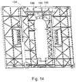
- FIG. 14shows the bottom of a table.
- FIG. 15shows a perspective view of a bracket used to hold down an insert.
- FIG. 16shows a front view of the bracket of FIG. 15 .
- FIG. 17shows a top view of the bracket of FIG. 15 .
- FIG. 18shows a side view of the bracket of FIG. 15 .
- FIG. 19shows a perspective view of a button used in a mechanism to hold down an insert.
- FIG. 20shows a back view of the bracket of FIG. 19 .
- FIG. 21shows a right side view of the bracket of FIG. 19 .
- FIG. 22shows a top view of the bracket of FIG. 19 .
- FIG. 23shows another perspective view of the bracket of FIG. 19 .
- FIG. 24shows a front view of the bracket of FIG. 19 .
- FIG. 25shows a left side view of the bracket of FIG. 19 .
- FIG. 26shows a bottom view of the bracket of FIG. 19 .
- FIG. 27shows a bracket, button and spring assembled for use in a mechanism to hold down an insert.
- FIG. 28shows another view of the assembly of FIG. 27 .
- FIG. 29shows a spring used in the assembly of FIG. 27 .
- FIG. 30shows a front view of the spring of FIG. 29 .
- FIG. 31shows a top view of the spring of FIG. 29 .
- FIG. 32shows a side view of the spring of FIG. 29 .
- FIG. 33shows another embodiment of a system to hold down the front of a table saw insert.
- FIG. 34shows the insert of FIG. 33 as it is being installed in a blade opening.
- FIG. 35shows the insert of FIG. 33 installed in a blade opening.
- FIG. 36shows a latch used in the embodiment of FIG. 33 .
- FIG. 37shows another embodiment of a system to hold down the front of a table saw insert.
- FIG. 38shows a latch used in the embodiment of FIG. 37 .
- FIG. 39shows still another embodiment of a system to hold down the front of a table saw insert.
- FIG. 40shows another view of the embodiment of FIG. 39 .
- FIG. 41shows a bracket used in the embodiment of FIG. 39 .
- FIG. 42shows a spring used in the embodiment of FIG. 39 .
- FIG. 43shows a screw used in the embodiment of FIG. 39 .
- FIG. 44shows yet another embodiment of a system to hold down the front of a table saw insert.
- FIG. 45shows a bracket used in the embodiment of FIG. 44 .
- FIG. 46shows a spring used in the embodiment of FIG. 44 .
- FIG. 1shows a table saw 100 with a blade opening 102 in a table 104 .
- a blade 106extends up through the table and opening, and an insert 108 surrounds the blade and covers the opening.
- FIGS. 2 through 9Various views of insert 108 are shown in FIGS. 2 through 9 .
- Insert 108is shaped to fit within blade opening 102 in the table.
- insert 108is shaped something like a long oval. Of course, other shapes are possible.
- Blade opening 102has four support tabs, or ledges, that extend a short ways inward into opening 102 from the underside of the table, two tabs 120 along the rear of opening 102 , and two tabs 122 , one along each side near the front of opening 102 , as shown in FIGS. 10 and 11 .
- Tabs 120 and 122support insert 108 when the insert is placed within the blade opening.
- the insertcan be adjusted so that the top surface of the insert is substantially coplanar with the top of table 104 by turning screws 136 , which thread through holes 138 in the insert and contact tabs 122 .
- insert 108has a slot 130 that runs from a wider opening 131 at the rear of the insert to near the front, and the blade extends through the slot.
- the insert depicted in FIGS. 1 through 9is a zero-clearance insert, so slot 130 is cut by the blade, as explained, and runs next to the blade along most of the slot's length.
- Slot 130connects with opening 131 at the rear of the slot (the rear of the slot is the portion of the slot furthest away from the front of the table saw when the insert is in the blade opening). Opening 131 allows room for a riving knife 132 or splitter to extend up through the insert.
- wear plates 134At the rear of opening 131 , on both sides, there are wear plates 134 to protect the surface of the insert from the sharp tips of anti-kickback pawls that may be installed on a splitter or blade guard.
- the rear of the insertcan be held down and/or locked into place in many ways.
- two screws 140are threaded into holes 141 from the bottom of the insert so that the heads of the screws extend down below the insert.
- Holes 141extend through the insert and the threaded ends of screws 140 have sockets so that a user can turn the screws from above the table by placing a wrench or driver into the sockets through holes 141 and turning.
- the heads of screws 140are used to hold the rear of the insert locked down when the insert is installed.
- two screws 144are threaded into holes in tabs 120 , and the heads of screws 140 slide under the heads of screws 144 so that the heads overlap to lock the rear of the insert in place, as described in U.S. Pat. No. 7,997,176, issued Aug. 16, 2011, which is hereby incorporated by reference.
- the insertmay include a tab that fits into a socket in the table, or that fits under an edge of the table, to hold the rear of the insert down.
- the front of the insertcan also be held down and/or locked in place in many ways.
- a screwextends down through the insert and threads into a hole in the table to lock the insert in place.
- a screwdriveris required to remove the insert, which makes the insert more difficult to remove and install.
- a knob, lever, latch or balemay be used to hold down the front of an insert, as described in U.S. Patent Application Publication 2011/0203438, published Aug. 25, 2011, which is hereby incorporated by reference. The devices described in that publication do not require a screwdriver or other tool to remove and install the insert.
- FIGS. 12 and 13show a mechanism to hold down the front of an insert that is simple to operate and that does not require a tool to install, lock, unlock or remove.
- FIG. 12shows the front end of an insert placed in a blade opening, looking down from above the table.
- the insertincludes a finger hole 196 and a button or tab 194 adjacent the finger hole so that a user can reach into the hole and press the button.
- the buttonis configured to be pressed toward the front of the saw to release the insert from the blade opening because pressing the button in that direction is a convenient, intuitive and simple movement when a finger is inserted into hole 196 .
- FIG. 13shows the hold-down mechanism, looking up from under the insert and table.
- a screw 146threads into the bottom of insert 108 adjacent the front of the insert. The screw threads into a hole 148 that extends through the insert, and the threaded end of screw 146 is accessible from above the insert, as shown in FIG. 12 .
- the threaded end of screw 146may include a socket so that a user can insert a wrench or other driver into the socket to turn the screw from above the insert to adjust the hold-down mechanism.
- the opposite end of screw 146has a button or flat head that provides a shoulder, and the screw head extends down from the underside of the insert to mesh with a bracket 152 .
- the shoulder on screw 146may be thought of as an example of a first edge.
- Bracket 152is attached to the bottom of table 104 by bolts, such as bolt 164 , that thread into sockets 166 (bolt 164 is shown in FIG. 13 and sockets 166 are shown in FIG. 14 ). Bracket 152 is shown isolated from other structure in FIGS. 15 through 18 .
- the bracketincludes a slot 150 configured to receive the shoulder of the head of screw 146 .
- the bracketis positioned so that when the insert is placed in the blade opening, the head of screw 146 fits into slot 150 in bracket 152 .
- the insertis locked down because the edge of the slot overlaps the head of screw 146 .
- Slot 150 in bracket 152may be thought of as an example of a second edge.
- Bracket 152includes two side sections 160 that extend up toward the underside of the table and that terminate in holes 162 .
- the bracketis mounted to the underside of the table by bolts passing through holes 162 .
- Bracket 152also includes a middle section 170 that includes slot 150 .
- Middle section 170bends out at about 15 degrees away from side sections 160 , and then, near the top, it bends back at about 30 degrees towards the side sections, where it bends again, making a rounded hump 172 that runs along the top of the bracket, and then flattens in the middle to form a square tab 174 that extends out from the middle of the top of the bracket and runs substantially parallel to the underside of the table.
- the small, narrow rectangular slot 150through which the end of the head of screw 146 fits, lies horizontally along a bend in the middle section, as shown in FIGS. 15 and 16 .
- middle section 170When insert 108 is placed in the blade opening in the table, the head of screw 146 will contact the upper part of middle section 170 of bracket 152 and cause the middle section to flex toward the front of the saw.
- the upper part of middle section 170provides a sloped surface to contact screw 146 so that the screw flexes the middle section forward (i.e., toward the front of the saw) as the screw slides down the middle section.
- the screwslides down middle section 170 until the head of screw 146 meets slot 150 , at which time the middle section springs back so that the head of screw 146 is captured in slot 150 , locking the insert down.
- middle section 170may be thought of as a spring or flex plate that catches screw 146 .
- Screw 146can be turned to adjust the position of the screw so that it meshes with slot 150 in bracket 152 . Turning screw 146 also adjusts the height of the front of the insert relative to the surface of the table, or in other words, turning screw 146 adjusts the position of the front of the insert relative to the table so that the top front of the insert is substantially coplanar with the top of the table.
- middle section 170includes a rectangular cutout 178 in tab 174 and hump 172 , and the cutout fits around a flange or protrusion 180 that extends downward from the underside of the table (protrusion 180 is shown in FIG. 14 ).
- protrusion 180is shown in FIG. 14 .
- cutout 178limits the movement of middle section 170 toward the front and rear of the saw, while still allowing the middle section to flex and move to accommodate installation of the insert.
- Hump 172functions like a stop to contact the underside of the table and prevent the insert from being removed from the blade opening if a user pulls the insert up without releasing screw 146 from bracket 152 .
- Button or tab 194is attached to middle section 170 of bracket 152 so that a user can press the button to flex the middle section and release screw 146 from slot 150 .
- Button 194is shown isolated in FIGS. 19 through 26 .
- Button 194has a generally square-shaped body with a tab 195 extending up from the body.
- the tabhas a generally concave surface 197 shaped to receive a finger.
- the body of button 194 opposite and below concave surface 197includes a hole 200 .
- Button 194attaches to middle section 170 of bracket 152 by a bolt 190 passing through a washer 192 , then passing through a hole 202 in the middle section of the bracket, and then threading into hole 200 in button 194 , as shown in FIGS. 27 and 28 .
- Hole 200 in button 194is surrounded by a slight projection 201 .
- the projectionis shaped and sized to fit into hole 202 in middle section 170 of bracket 152 .
- Projection 201 and hole 202are generally circular in shape, but include a small key and key hole, respectively, extending out from the perimeter of the circle so that button 194 does not rotate in hole 202 (the key hole in hole 202 is identified by number 203 in FIG. 16 ).
- FIG. 28shows another view of button 194 attached to bracket 152 .
- the mechanism to secure the front of the insertincludes a spring that causes the front of the insert to pop up above the table when button 194 is pressed to release the insert.
- a spring 204formed from a metal wire, is secured to the underside of the table by bolt 164 , as shown in FIG. 13 .
- Spring 204is shown isolated in FIGS. 29 through 32 , and the spring includes a loop 205 at one end through which bolt 164 passes to secure the spring in the saw.
- Spring 204runs along the outer surface of middle section 170 of bracket 152 , as shown in FIGS. 13 , 27 and 28 .
- the end of spring 204 opposite loop 205extends into a recess 206 in the side of button 194 , as shown in FIG.
- Spring 204is shaped and positioned so that it presses up against the head of screw 146 when insert 108 is placed in blade opening 102 . As insert 108 is placed in blade opening 102 , screw 146 contacts and flexes spring 204 as the screw moves down and slips or snaps into slot 150 in bracket 152 . The screw is then held in position by slot 150 and spring 204 is held flexed by screw 146 until a user presses button 194 .
- middle section 170 of bracket 152is flexed away from screw 146 until the screw is released from slot 150 , at which time spring 204 pushes screw 146 and the front of insert 108 up.
- the throw of spring 204 , and the position of screw 146are configured so that the spring pushes the front of the insert up above the top of table 104 .
- the springmay push the front of the insert up approximately 12 millimeters, more or less, above the top of the table. This provides the user of the table saw with a visual and tactile indication when the insert is not fully or properly installed and secured in the blade opening.
- Spring 204also works with middle section 170 of bracket 152 to provide at least some resistance and/or tension against the insert, which helps prevent the insert from vibrating and rattling in the blade opening when the table saw is running. That resistance and/or tension also provides a “feel” to a user when the user installs the insert in the blade opening that indicates the insert is being positioned and installed correctly.
- a userwould first angle the insert into the blade opening so that the rear of the insert locks in place, such as by screws in the rear of the insert overlapping screws near the rear of the blade opening or by a tab extending from the end of the insert fitting under a lip in the table, as described. The user would then simply press down on the front of the insert until the insert “snapped” in place by screw 146 fitting into slot 150 in bracket 152 .
- Both the front and rear of the insertare then latched down, i.e., held down mechanically and affirmatively due to overlapping edges of components, which is more than a simple friction fit as in other table saws, and a tool is not required to accomplish the mechanical hold-down as in saws where the insert is screwed down. No action other than pressing down the front of the insert is necessary to secure the insert in place; a user need not manipulate a knob, handle, lever or bale to lock the insert in place.
- button 194extends at least partially into hole 196 , as described, so the button is easily accessible by a user.
- Hole 196is sized and shaped to accommodate a finger, but is small enough or obstructed with a flange or other surface so that a user cannot extend his finger into the hole and contact the saw blade.
- Inserts as described hereinwhen used in a saw having active injury mitigation technology, can be made of phenolic or wood.
- Phenolic and woodare both non-conductive, which is necessary for active injury mitigation systems, and are rigid, which is necessary to maintain a flat, supportive surface for a work piece, especially given that a blade slot cut in the insert decreases the overall structural rigidity of the insert.
- Phenolic and woodare relatively expensive, and a more economical material would result in lower costs.
- an insertcan be made out of metal overmolded with plastic, but those inserts involve extra manufacturing steps.
- an insert as described hereincan be made from approximately 50% glass filled nylon 6. Inserts made from that material are non-conductive, sufficiently rigid, and can be manufactured easily and relatively inexpensively by injection molding. Additionally, approximately 50% glass filled nylon 6 resists scratching and has little discoloration (i.e., it holds color well).
- FIGS. 2 through 9show an insert made from approximately 50% glass filled nylon 6.
- the bottom surface of the insertincludes ribs to provide structural rigidity, such as ribs 250 , 252 and 254 identified in FIG. 6 .
- the ribsextend in different directions to provide rigidity both across the width of the insert and along the length of the insert.
- Some sections of the insertmay not have ribs in order to provide clearance for components in the table saw, such as an arbor block or riving knife mount, which can extend close to the bottom of the insert when the blade is raised to its full elevation. Additionally, an elongate center section of the insert does not have ribs in order to provide an area for blade slot 130 .
- Rib 250borders a side of the area around blade slot 130 , and rib 250 is as tall as possible to provide as much rigidity as possible along blade slot 130 .
- Rib 254borders the opposite side of the blade slot, but rib 254 cannot be as tall as rib 250 because clearance is necessary for the blade to tilt so that a user can make bevel or angled cuts.
- Other ribscan have varying heights, as seen in FIG. 7 , to provide clearance or extra rigidity.
- FIG. 33Another embodiment of a system to hold down the front of a table saw insert is shown in FIG. 33 .
- a latch 300is mounted to the bottom of an insert 302 by a screw 304 so that the latch can pivot around the screw.
- FIG. 33shows the front end of the insert, looking up at the bottom of the insert.
- the latchincludes an arm 306 that extends under a finger hole 308 in the insert so that a user can insert a finger through the hole and move the arm to pivot the latch around screw 304 .
- the latchalso includes a flange 310 with a flat upper surface 316 (labeled in FIG. 36 ) and a sloped or angled lower surface 311 (labeled in FIG. 35 ).
- the flat upper surfaceis configured to overlap a shelf on the table to lock the insert in the blade opening.
- the flat upper surfacemay be thought of as an example of a first edge.
- the angled lower surfaceis configured to engage the shelf on the table and cause the latch to pivot as the insert is pressed down into the blade opening. The latch pivots until flange 310 clears the shelf, at which time a spring 312 pushes the latch back so that the upper surface of flange 310 overlaps the shelf to hold the insert in place.
- FIG. 34shows insert 302 positioned over but not yet seated in the blade opening in the table, looking up from underneath the table toward the bottom of the insert.
- Latch 300is positioned over shelf 314 in the table, but is not engaged with the shelf.
- FIG. 35shows the same insert seated in the blade opening with latch 300 engaging shelf 314 so that the insert is held in place in the blade opening.
- the upper surface of flange 310 of latch 300overlaps shelf 314 to hold the insert in place.
- the shelf 314may be thought of as an example of a second edge.
- FIG. 36shows a top perspective view of latch 300 isolated from other structure.
- FIG. 37shows another embodiment of a system to hold down the front of a table saw insert, with a latch 320 similar to latch 300 discussed above, but without a sloped or angled lower surface. Instead, latch 320 includes a flat lower surface 322 . In this embodiment, a user must pivot the latch both to install and remove the insert from the blade opening.
- FIG. 38shows latch 320 isolated from other structure.
- FIGS. 39 and 40show still another embodiment of a system to hold down the front of a table saw insert.
- a screw 340extends down from the underside of an insert 342 .
- a bracket 344is attached to the bottom of the table and the head of screw 340 fits into a slot 346 in the bracket to hold the insert down.
- the head of screw 340may be thought of as an example of a first edge, and slot 346 may be thought of as an example of a second edge.
- the bracketincludes a sloped portion 348 , and the head of screw 340 contacts the sloped portion and flexes the bracket away as the insert is pushed down into the blade opening until the head of the screw meshes with slot 346 . At that point, the bracket flexes back and the slot overlaps the head of screw 340 to hold the insert in place.
- Bracket 344includes a finger tab 350 positioned under a finger hole in the insert. A user can push the tab toward the front of the saw, thereby flexing bracket 344 and freeing screw 340 from slot 346 .
- a spring 352is positioned to press against the head of screw 340 and the spring is flexed when the insert is installed in the blade opening so when screw 340 is free from slot 346 , spring 352 pushes the front of the insert up above the top of the table.
- FIG. 41shows bracket 344 isolated from other structure.
- FIG. 42shows spring 352 by itself.
- FIG. 43shows screw 340 .
- FIG. 44shows another similar embodiment of a system to hold down the front of a table saw insert.
- a screw 360extends down from the bottom of the insert and fits into a slot 362 in a bracket 364 .
- a spring 366is mounted to the underside of the table and positioned to press up against screw 360 .
- the head of screw 360may be thought of as an example of a first edge, and slot 362 may be thought of as an example of a second edge.
- This embodimentfunctions similarly to the embodiment shown in FIGS. 39 and 40 .
- a userreleases the insert by flexing the center of bracket 364 toward the front of the table saw to release screw 360 from slot 362 . When released, spring 366 pushes the front of the insert up.
- the inserts described hereinare applicable to woodworking power tool equipment, and particularly to table saws.
Landscapes
- Engineering & Computer Science (AREA)
- Mechanical Engineering (AREA)
- Sawing (AREA)
Abstract
Description
Claims (1)
Priority Applications (1)
| Application Number | Priority Date | Filing Date | Title |
|---|---|---|---|
| US15/924,797US11548083B2 (en) | 2010-02-19 | 2018-03-19 | Inserts for table saws |
Applications Claiming Priority (5)
| Application Number | Priority Date | Filing Date | Title |
|---|---|---|---|
| US33849310P | 2010-02-19 | 2010-02-19 | |
| US12/931,809US10589366B2 (en) | 2010-02-19 | 2011-02-11 | Table saw insert with lock-down mechanism |
| US201361892231P | 2013-10-17 | 2013-10-17 | |
| US14/517,522US9919369B2 (en) | 2013-10-17 | 2014-10-17 | Inserts for table saws |
| US15/924,797US11548083B2 (en) | 2010-02-19 | 2018-03-19 | Inserts for table saws |
Related Parent Applications (1)
| Application Number | Title | Priority Date | Filing Date |
|---|---|---|---|
| US14/517,522ContinuationUS9919369B2 (en) | 2010-02-19 | 2014-10-17 | Inserts for table saws |
Publications (2)
| Publication Number | Publication Date |
|---|---|
| US20180207735A1 US20180207735A1 (en) | 2018-07-26 |
| US11548083B2true US11548083B2 (en) | 2023-01-10 |
Family
ID=52825026
Family Applications (2)
| Application Number | Title | Priority Date | Filing Date |
|---|---|---|---|
| US14/517,522Active2035-02-05US9919369B2 (en) | 2010-02-19 | 2014-10-17 | Inserts for table saws |
| US15/924,797Active2032-11-17US11548083B2 (en) | 2010-02-19 | 2018-03-19 | Inserts for table saws |
Family Applications Before (1)
| Application Number | Title | Priority Date | Filing Date |
|---|---|---|---|
| US14/517,522Active2035-02-05US9919369B2 (en) | 2010-02-19 | 2014-10-17 | Inserts for table saws |
Country Status (1)
| Country | Link |
|---|---|
| US (2) | US9919369B2 (en) |
Families Citing this family (11)
| Publication number | Priority date | Publication date | Assignee | Title |
|---|---|---|---|---|
| US9724840B2 (en) | 1999-10-01 | 2017-08-08 | Sd3, Llc | Safety systems for power equipment |
| US9927796B2 (en) | 2001-05-17 | 2018-03-27 | Sawstop Holding Llc | Band saw with improved safety system |
| US10022811B2 (en)* | 2009-07-31 | 2018-07-17 | Sawstop Holding Llc | Dust collection system for a table saw |
| US9919369B2 (en)* | 2013-10-17 | 2018-03-20 | Sawstop Holding Llc | Inserts for table saws |
| CN207189852U (en) | 2017-06-05 | 2018-04-06 | 米沃奇电动工具公司 | Bench saw |
| CN111051009B (en) | 2017-08-30 | 2023-06-16 | 米沃奇电动工具公司 | Power Tools with Object Detection |
| CN108638157A (en)* | 2018-05-23 | 2018-10-12 | 温州晨辉包装材料有限公司 | A kind of high-accuracy digital cutting machine |
| CN109290626A (en)* | 2018-10-25 | 2019-02-01 | 杭州富阳飞尚装饰工程有限公司 | A kind of plate cutting device and its application method of interior decoration |
| DE102019200366A1 (en) | 2019-01-14 | 2020-07-16 | Festool Gmbh | Saw blade cover, fence unit and table saw |
| US11383401B2 (en)* | 2019-06-13 | 2022-07-12 | Techtronic Cordless Gp | Table saw |
| WO2021163057A1 (en)* | 2020-02-10 | 2021-08-19 | Sawstop Holding Llc | Power saws |
Citations (65)
| Publication number | Priority date | Publication date | Assignee | Title |
|---|---|---|---|---|
| US1183383A (en) | 1915-10-26 | 1916-05-16 | Thomas E Jenkins | Safety device for saws. |
| US1816069A (en) | 1928-11-02 | 1931-07-28 | Ernest W Bennett | Woodworking machine |
| US1938548A (en) | 1933-02-04 | 1933-12-05 | Delts Mfg Company | Machine table extension |
| US2008673A (en) | 1934-03-07 | 1935-07-23 | Walker Turner Company Inc | Power-driven tool |
| US2020222A (en)* | 1935-04-08 | 1935-11-05 | Delta Mfg Co | Machine table insert |
| US2067652A (en)* | 1934-08-04 | 1937-01-12 | Herbert E Tautz | Woodworking machine |
| US2294272A (en) | 1939-03-17 | 1942-08-25 | William B Boice | Woodworking machine |
| US2394034A (en) | 1943-11-04 | 1946-02-05 | Armstrong Blum Mfg Company | Saw blade holder |
| US2403247A (en) | 1942-12-19 | 1946-07-02 | Lockheed Aircraft Corp | Fastening device |
| US2569914A (en) | 1948-08-06 | 1951-10-02 | Appleton Electric Co | Cover clamp |
| US2593596A (en) | 1949-03-24 | 1952-04-22 | George V Olson | Circular saw guard |
| US2615479A (en)* | 1948-06-14 | 1952-10-28 | Roswell D Bearup | Woodsawing machine and shaper attachment therefor |
| US2786500A (en)* | 1954-03-26 | 1957-03-26 | Joseph G Unterfranz | Combination carrying case and table for portable power tool |
| US2810412A (en) | 1955-12-27 | 1957-10-22 | George A Roug | Supporting apparatus for a portable rotary power saw |
| CA731978A (en) | 1966-04-12 | J. Kwiatkowski Rudolph | Miter table and saw | |
| US3269433A (en) | 1964-09-02 | 1966-08-30 | Toolkraft Corp | Multi-purpose woodworking tools |
| US3285303A (en)* | 1964-09-25 | 1966-11-15 | Rudolph J Kwiatkowski | Miter table and saw |
| US3289713A (en)* | 1964-10-26 | 1966-12-06 | Emerson Electric Co | Machinery table insert |
| US3386482A (en) | 1966-01-11 | 1968-06-04 | Nadeau James Harold | Portable rotary cut-off saw with guide means for accurately locating a workpiece thereupon |
| US3490637A (en) | 1968-06-24 | 1970-01-20 | Robert M Pope | Utility marker box |
| US3866502A (en) | 1974-03-08 | 1975-02-18 | Sr Clarence R Brewer | Gang rip saw |
| US4031934A (en) | 1976-09-01 | 1977-06-28 | Rigo Stadler | Adjustable router bit |
| US4058070A (en) | 1976-09-07 | 1977-11-15 | Edna Jones | See-through sewing gauge |
| US4095632A (en) | 1977-08-01 | 1978-06-20 | Raulinaitis John M | Straight edge cutting guide for router and circular saw |
| US4150633A (en) | 1978-02-28 | 1979-04-24 | The Singer Company | Snap-on darning and embroidery plate |
| US4159003A (en) | 1978-04-10 | 1979-06-26 | The Singer Company | Convertible work feeding device for sewing machines |
| US4194456A (en) | 1979-03-15 | 1980-03-25 | The Singer Company | Blind stitch mechanism |
| US4335765A (en) | 1979-11-23 | 1982-06-22 | Murphy Rholand D | Portable multi-purpose construction table |
| US4350193A (en) | 1980-05-01 | 1982-09-21 | Central Quality Industries, Inc. | Power tool accessory table |
| US4395962A (en) | 1981-09-23 | 1983-08-02 | The Singer Company | Straight stitch throat plate for a sewing machine |
| US4487330A (en) | 1984-01-05 | 1984-12-11 | Square D Company | Trim clamp assembly |
| US4543866A (en) | 1983-01-26 | 1985-10-01 | Peter Maier | Table saw outfit |
| US4635692A (en) | 1983-12-22 | 1987-01-13 | Meritcraft Ltd. | Workbench |
| US4694763A (en) | 1980-08-20 | 1987-09-22 | Ssmc Inc. | Sewing machine bed slide retention |
| US5013195A (en) | 1989-05-15 | 1991-05-07 | Frank Strazar | Router guide |
| US5159864A (en)* | 1991-09-23 | 1992-11-03 | Wedemeyer Arlan B | Insert for a table saw |
| US5231906A (en) | 1992-09-30 | 1993-08-03 | Julien Kogej | Table saw guard |
| US5398740A (en) | 1993-11-12 | 1995-03-21 | Miller; Manford B. | Power tool table with adjustable tool mounting plate insert and related method |
| US5725038A (en) | 1996-08-29 | 1998-03-10 | Lee Valley Tools Ltd. | Router baseplate and table |
| US5855234A (en) | 1997-07-14 | 1999-01-05 | Ryobi North America Inc. | Router table assembly with microset throat plate |
| US5857507A (en) | 1996-09-20 | 1999-01-12 | Black & Decker Inc. | Table saw |
| US5901631A (en)* | 1997-09-18 | 1999-05-11 | Minarovic; Mike | Wood notching system |
| US5970835A (en)* | 1998-09-10 | 1999-10-26 | Black & Decker Inc. | Throat plate for a tool |
| US6216575B1 (en) | 1999-02-12 | 2001-04-17 | One World Technologies Inc. | Table saw throat plate with blade height scale |
| US20010035081A1 (en) | 1998-07-08 | 2001-11-01 | Stephen O. Sutton | Splitter and cutting member guard assembly |
| US6418829B1 (en) | 1994-05-06 | 2002-07-16 | Thomas Stanley Pilchowski | Power tool safety device |
| US6431042B1 (en) | 1994-05-13 | 2002-08-13 | Milwaukee Electric Tool Corporation | Turntable mechanism for a cutting tool |
| US20040159200A1 (en)* | 2003-02-18 | 2004-08-19 | Thomas Stoffel | Zero-clearance table saw insert |
| US20040232298A1 (en) | 2003-04-11 | 2004-11-25 | Jeff Bremmon | Flat panel display mounting system |
| US20040255745A1 (en)* | 2003-06-23 | 2004-12-23 | One World Technologies Limited | Table saw guard assembly |
| US6840144B2 (en) | 2002-07-17 | 2005-01-11 | Durq Machinery Corp. | Quick-detachable blade guard mounting structure |
| US6900728B2 (en) | 2002-07-29 | 2005-05-31 | Home Depot U.S.A., Inc. | System to detect user entry into a defined danger zone |
| US20050188806A1 (en) | 2002-10-31 | 2005-09-01 | Garcia Jaime E. | Riving knife assembly for a dual bevel table saw |
| US6942229B2 (en) | 2003-10-31 | 2005-09-13 | One World Technologies Limited | Collapsible stand for a bench-top power tool |
| US20060219076A1 (en) | 2005-03-31 | 2006-10-05 | Gass Stephen F | Table saw throat plates and table saws including the same |
| US7134373B1 (en)* | 2004-02-23 | 2006-11-14 | James Perry Vice | Throat insert for a table saw |
| US7210386B1 (en) | 2005-11-02 | 2007-05-01 | Kingsand Machinery Ltd. | Quickly detachable protective cover unit of a table sawing machine |
| US7827890B2 (en) | 2004-01-29 | 2010-11-09 | Sd3, Llc | Table saws with safety systems and systems to mount and index attachments |
| US20110203438A1 (en)* | 2010-02-19 | 2011-08-25 | Nenadic John P | Table saw insert with lock-down mechanism |
| US8079295B2 (en)* | 2008-06-20 | 2011-12-20 | Sd3, Llc | Table saw blade guards and blade guard assemblies including lateral blade guards, and table saws including the same |
| US20120007301A1 (en) | 2010-07-09 | 2012-01-12 | James Liu | Worktable and its Protective Member |
| TW201201936A (en)* | 2010-07-07 | 2012-01-16 | Rexon Ind Corp Ltd | A table insert mounting structure for saw machine |
| US8122798B1 (en) | 2008-11-19 | 2012-02-28 | Power Tool Institute | Power cutting tool with proximity sensing system |
| US9878380B2 (en)* | 1999-10-01 | 2018-01-30 | Sawstop Holding Llc | Table saw throat plates and table saws including the same |
| US9919369B2 (en)* | 2013-10-17 | 2018-03-20 | Sawstop Holding Llc | Inserts for table saws |
Family Cites Families (1)
| Publication number | Priority date | Publication date | Assignee | Title |
|---|---|---|---|---|
| US3581784A (en)* | 1969-11-21 | 1971-06-01 | Rockwell Mfg Co | Saw table insert |
- 2014
- 2014-10-17USUS14/517,522patent/US9919369B2/enactiveActive
- 2018
- 2018-03-19USUS15/924,797patent/US11548083B2/enactiveActive
Patent Citations (70)
| Publication number | Priority date | Publication date | Assignee | Title |
|---|---|---|---|---|
| CA731978A (en) | 1966-04-12 | J. Kwiatkowski Rudolph | Miter table and saw | |
| US1183383A (en) | 1915-10-26 | 1916-05-16 | Thomas E Jenkins | Safety device for saws. |
| US1816069A (en) | 1928-11-02 | 1931-07-28 | Ernest W Bennett | Woodworking machine |
| US1938548A (en) | 1933-02-04 | 1933-12-05 | Delts Mfg Company | Machine table extension |
| US2008673A (en) | 1934-03-07 | 1935-07-23 | Walker Turner Company Inc | Power-driven tool |
| US2067652A (en)* | 1934-08-04 | 1937-01-12 | Herbert E Tautz | Woodworking machine |
| US2020222A (en)* | 1935-04-08 | 1935-11-05 | Delta Mfg Co | Machine table insert |
| US2294272A (en) | 1939-03-17 | 1942-08-25 | William B Boice | Woodworking machine |
| US2403247A (en) | 1942-12-19 | 1946-07-02 | Lockheed Aircraft Corp | Fastening device |
| US2394034A (en) | 1943-11-04 | 1946-02-05 | Armstrong Blum Mfg Company | Saw blade holder |
| US2615479A (en)* | 1948-06-14 | 1952-10-28 | Roswell D Bearup | Woodsawing machine and shaper attachment therefor |
| US2569914A (en) | 1948-08-06 | 1951-10-02 | Appleton Electric Co | Cover clamp |
| US2593596A (en) | 1949-03-24 | 1952-04-22 | George V Olson | Circular saw guard |
| US2786500A (en)* | 1954-03-26 | 1957-03-26 | Joseph G Unterfranz | Combination carrying case and table for portable power tool |
| US2810412A (en) | 1955-12-27 | 1957-10-22 | George A Roug | Supporting apparatus for a portable rotary power saw |
| US3269433A (en) | 1964-09-02 | 1966-08-30 | Toolkraft Corp | Multi-purpose woodworking tools |
| US3285303A (en)* | 1964-09-25 | 1966-11-15 | Rudolph J Kwiatkowski | Miter table and saw |
| US3289713A (en)* | 1964-10-26 | 1966-12-06 | Emerson Electric Co | Machinery table insert |
| US3386482A (en) | 1966-01-11 | 1968-06-04 | Nadeau James Harold | Portable rotary cut-off saw with guide means for accurately locating a workpiece thereupon |
| US3490637A (en) | 1968-06-24 | 1970-01-20 | Robert M Pope | Utility marker box |
| US3866502A (en) | 1974-03-08 | 1975-02-18 | Sr Clarence R Brewer | Gang rip saw |
| US4031934A (en) | 1976-09-01 | 1977-06-28 | Rigo Stadler | Adjustable router bit |
| US4058070A (en) | 1976-09-07 | 1977-11-15 | Edna Jones | See-through sewing gauge |
| US4095632A (en) | 1977-08-01 | 1978-06-20 | Raulinaitis John M | Straight edge cutting guide for router and circular saw |
| US4150633A (en) | 1978-02-28 | 1979-04-24 | The Singer Company | Snap-on darning and embroidery plate |
| US4159003A (en) | 1978-04-10 | 1979-06-26 | The Singer Company | Convertible work feeding device for sewing machines |
| US4194456A (en) | 1979-03-15 | 1980-03-25 | The Singer Company | Blind stitch mechanism |
| US4335765A (en) | 1979-11-23 | 1982-06-22 | Murphy Rholand D | Portable multi-purpose construction table |
| US4350193A (en) | 1980-05-01 | 1982-09-21 | Central Quality Industries, Inc. | Power tool accessory table |
| US4694763A (en) | 1980-08-20 | 1987-09-22 | Ssmc Inc. | Sewing machine bed slide retention |
| US4395962A (en) | 1981-09-23 | 1983-08-02 | The Singer Company | Straight stitch throat plate for a sewing machine |
| US4543866A (en) | 1983-01-26 | 1985-10-01 | Peter Maier | Table saw outfit |
| US4635692A (en) | 1983-12-22 | 1987-01-13 | Meritcraft Ltd. | Workbench |
| US4487330A (en) | 1984-01-05 | 1984-12-11 | Square D Company | Trim clamp assembly |
| US5013195A (en) | 1989-05-15 | 1991-05-07 | Frank Strazar | Router guide |
| US5159864A (en)* | 1991-09-23 | 1992-11-03 | Wedemeyer Arlan B | Insert for a table saw |
| US5231906A (en) | 1992-09-30 | 1993-08-03 | Julien Kogej | Table saw guard |
| US5398740A (en) | 1993-11-12 | 1995-03-21 | Miller; Manford B. | Power tool table with adjustable tool mounting plate insert and related method |
| US6418829B1 (en) | 1994-05-06 | 2002-07-16 | Thomas Stanley Pilchowski | Power tool safety device |
| US6431042B1 (en) | 1994-05-13 | 2002-08-13 | Milwaukee Electric Tool Corporation | Turntable mechanism for a cutting tool |
| US5725038A (en) | 1996-08-29 | 1998-03-10 | Lee Valley Tools Ltd. | Router baseplate and table |
| US5857507A (en) | 1996-09-20 | 1999-01-12 | Black & Decker Inc. | Table saw |
| US5855234A (en) | 1997-07-14 | 1999-01-05 | Ryobi North America Inc. | Router table assembly with microset throat plate |
| US5901631A (en)* | 1997-09-18 | 1999-05-11 | Minarovic; Mike | Wood notching system |
| US20010035081A1 (en) | 1998-07-08 | 2001-11-01 | Stephen O. Sutton | Splitter and cutting member guard assembly |
| US6076445A (en) | 1998-09-10 | 2000-06-20 | Black & Decker Inc. | Throat plate for a tool |
| US6422116B1 (en) | 1998-09-10 | 2002-07-23 | Black & Decker Inc. | Throat plate for a tool |
| US5970835A (en)* | 1998-09-10 | 1999-10-26 | Black & Decker Inc. | Throat plate for a tool |
| US6216575B1 (en) | 1999-02-12 | 2001-04-17 | One World Technologies Inc. | Table saw throat plate with blade height scale |
| US9878380B2 (en)* | 1999-10-01 | 2018-01-30 | Sawstop Holding Llc | Table saw throat plates and table saws including the same |
| US6840144B2 (en) | 2002-07-17 | 2005-01-11 | Durq Machinery Corp. | Quick-detachable blade guard mounting structure |
| US6900728B2 (en) | 2002-07-29 | 2005-05-31 | Home Depot U.S.A., Inc. | System to detect user entry into a defined danger zone |
| US20050188806A1 (en) | 2002-10-31 | 2005-09-01 | Garcia Jaime E. | Riving knife assembly for a dual bevel table saw |
| US7249549B2 (en) | 2003-02-18 | 2007-07-31 | Thomas Stoffel | Zero-clearance table saw insert |
| US20040159200A1 (en)* | 2003-02-18 | 2004-08-19 | Thomas Stoffel | Zero-clearance table saw insert |
| US20040232298A1 (en) | 2003-04-11 | 2004-11-25 | Jeff Bremmon | Flat panel display mounting system |
| US20040255745A1 (en)* | 2003-06-23 | 2004-12-23 | One World Technologies Limited | Table saw guard assembly |
| US6942229B2 (en) | 2003-10-31 | 2005-09-13 | One World Technologies Limited | Collapsible stand for a bench-top power tool |
| US7866239B2 (en)* | 2003-12-31 | 2011-01-11 | Sd3, Llc | Elevation mechanism for table saws |
| US7827890B2 (en) | 2004-01-29 | 2010-11-09 | Sd3, Llc | Table saws with safety systems and systems to mount and index attachments |
| US7134373B1 (en)* | 2004-02-23 | 2006-11-14 | James Perry Vice | Throat insert for a table saw |
| US20060219076A1 (en) | 2005-03-31 | 2006-10-05 | Gass Stephen F | Table saw throat plates and table saws including the same |
| US7997176B2 (en)* | 2005-03-31 | 2011-08-16 | Sd3, Llc | Table saw throat plates and table saws including the same |
| US7210386B1 (en) | 2005-11-02 | 2007-05-01 | Kingsand Machinery Ltd. | Quickly detachable protective cover unit of a table sawing machine |
| US8079295B2 (en)* | 2008-06-20 | 2011-12-20 | Sd3, Llc | Table saw blade guards and blade guard assemblies including lateral blade guards, and table saws including the same |
| US8122798B1 (en) | 2008-11-19 | 2012-02-28 | Power Tool Institute | Power cutting tool with proximity sensing system |
| US20110203438A1 (en)* | 2010-02-19 | 2011-08-25 | Nenadic John P | Table saw insert with lock-down mechanism |
| TW201201936A (en)* | 2010-07-07 | 2012-01-16 | Rexon Ind Corp Ltd | A table insert mounting structure for saw machine |
| US20120007301A1 (en) | 2010-07-09 | 2012-01-12 | James Liu | Worktable and its Protective Member |
| US9919369B2 (en)* | 2013-10-17 | 2018-03-20 | Sawstop Holding Llc | Inserts for table saws |
Non-Patent Citations (37)
| Title |
|---|
| Bosch 10″ Table Saw Model 0601476139 Parts List and Technical Bulletin, S-B Power Tool Company, Apr. 2001. |
| Bosch Model 4000 Worksite Table Saw Operating/Safety Instructions, S-B Power Tool Company, Jul. 2000. |
| Delta Biesemeyer 10″ Table Saw Blade Guard Systems Instruction Manual, Delta Machinery, May 9, 2005. |
| DeWalt Woodworker's Table Saw DW746 Instruction Manual, DeWalt Industrial Tool Co., 2000. |
| Grizzly Industrial, Inc. Heavy-Duty 12″ Table Saw Model G5959 and G9957 Parts List, 1998 and Oct. 2001. |
| Grizzly Industrial, Inc. Model G0605X/G0606X Extreme Series 12″ Table Saw Owner's Manual, Grizzly Industrial, Inc., Oct. 2006. |
| Inca 2100SE Professional Tablesaw Owners Manual, Injecta Machinery, 1992. |
| IWF 2000 Challengers Award Official Entry Form, submitted Apr. 26, 2000, 6 pages plus CD (the portions of U.S. patent applications referenced in the form are from U.S. Appl. No. 60/157,340, filed Oct. 1, 1999 and U.S. Appl. No. 60/182,866, filed Feb. 16, 2000). |
| Laguna Tools table saw owner's manual, date unkown. |
| Makita Model 2704 Exploded Drawings and Parts List, Nov. 2005. |
| Makita Table Saw 2704 Instruction Manual, Makita Corporation of America, date unknown. |
| Porter Cable 10″ Portable Table Saw Model 3812 Parts List with Guard Exploded View, 2005. |
| Porter-Cable 10″ Portable Table Saw 3812, Porter-Cable Corporation, 2005. |
| Porter-Cable Double Insulated 10″ Bench Top Table Saw Instruction Manual, Porter-Cable Corporation, Sep. 15, 2003. |
| Powermatic 10″ Tilting Arbor Saw Model 66 Instruction Manual & Parts List, JET Equipment & Tools, Jun. 2001. |
| Powermatic WMH Tool Group Operating Instructions and Parts Manual 10-inch Cabinet Saw Model 2000, Nov. 2005. |
| Powermatic, Accu-Fence for the Models 66, 72A & 74A Table Saws Instruction Manual & Parts List, undated. |
| Ridgid TS3650 Operators Manual 10″ Cast Iron Table Saw, May 2003, Jun. 2003 and Jul. 15, 2003. |
| Rojek Circular Saw PK 300 Spare part catalogue, Apr. 14, 2003. |
| Rojek KPF 300A-xxxx-RN-1P3 Table Saw/Shaper Combination Machine specification sheet, Sep. 30, 2002. |
| Ryobi 10″ Table Saw BT3000 Operator's Manual, Ryobi Technologies, Inc., Mar. 2001. |
| Ryobi 10″ Table Saw BT3100 Operator's Manual, Ryobi Technologies, Inc., Aug. 2002. |
| SC 3W Circular Saw Manual, SCM Group S.p.A Divisione Minimax—Samco, Feb. 2001. |
| SCM Group publication, Rimini, Italy, undated. |
| SCM SI 450 Circular saw with tilting blade product brochure, Villa Verucchio, Italy, undated. |
| Shop Fox® Fence Operating Manual, Woodstock International, Inc., 1996, revised May 1997. |
| SI16WA-WF Circular Saw with Tilting Blade Spare Parts Catalogue, SCMI Corporation, Norcross, GA, Nov. 1986 and 1991. |
| SI300N Circular with Tilting Blade Spare Parts Catalogue, SCM, Jun. 12, 2000. |
| SI300S-SI300S4 Circular with Tilting Blade Spare Parts Catalogue, SCM, Oct. 30, 2003. |
| SI320 Circular with Tilting Blade Spare Parts Catalogue, SCM, Dec. 23, 1998. |
| SI3200/3800 Circular with Tilting Blade Spare Parts Catalogue, SCM, Dec. 23, 1998. |
| SI400N Circular with Tilting Blade Spare Parts Catalogue, SCM, Sep. 19, 2000. |
| SI450E Circular with Tilting Blade Spare Parts Catalogue, SCM, Apr. 26, 2001. |
| Skil Model 3400 Table Saw Operating/Safety Instructions, S-B Power Tool Co., Sep. 2001. |
| Skil Model 3400-Type 1 10″ Table Saw Parts List and Technical Bulletin, S-B Power Tool Company, Jun. 1993. |
| The Merlin Splitter by Excalibur a Sommerville Design Product Overview & Generic Installation Notes, Sommerville Design &.Manufacturing Inc., at least as early as 2002. |
| Two photographs of a saw displayed at a trade show on Aug. 23, 2000. |
Also Published As
| Publication number | Publication date |
|---|---|
| US20150107430A1 (en) | 2015-04-23 |
| US20180207735A1 (en) | 2018-07-26 |
| US9919369B2 (en) | 2018-03-20 |
Similar Documents
| Publication | Publication Date | Title |
|---|---|---|
| US11548083B2 (en) | Inserts for table saws | |
| US12257639B2 (en) | Miter saw | |
| US10882207B2 (en) | Table saws with safety systems and systems to mount and index attachments | |
| US20200376574A1 (en) | Table saws | |
| US7827893B2 (en) | Elevation mechanism for table saws | |
| US7814818B2 (en) | Modular table saw guarding system riving knife release mechanisms | |
| US20180333792A1 (en) | Table saw | |
| EP1882569B1 (en) | Table saw with a riving knife system and method for using a table saw with a riving knife system | |
| US20040060412A1 (en) | Adjustment device for a compound miter saw | |
| US20180133816A1 (en) | Miter saw | |
| US20150320204A1 (en) | Clamp for surface-mounted devices | |
| US11213971B2 (en) | Adjustable blade guard with dust collection | |
| US12275074B2 (en) | Power saws | |
| US20100206153A1 (en) | Spreader mounting structure for saw machine | |
| US20100101391A1 (en) | Quick-release mechanism for saw machine | |
| JP5920020B2 (en) | Portable cutting machine |
Legal Events
| Date | Code | Title | Description |
|---|---|---|---|
| FEPP | Fee payment procedure | Free format text:ENTITY STATUS SET TO UNDISCOUNTED (ORIGINAL EVENT CODE: BIG.); ENTITY STATUS OF PATENT OWNER: LARGE ENTITY | |
| STPP | Information on status: patent application and granting procedure in general | Free format text:DOCKETED NEW CASE - READY FOR EXAMINATION | |
| STPP | Information on status: patent application and granting procedure in general | Free format text:NON FINAL ACTION MAILED | |
| STPP | Information on status: patent application and granting procedure in general | Free format text:RESPONSE TO NON-FINAL OFFICE ACTION ENTERED AND FORWARDED TO EXAMINER | |
| STPP | Information on status: patent application and granting procedure in general | Free format text:NON FINAL ACTION MAILED | |
| AS | Assignment | Owner name:SAWSTOP HOLDING LLC, OREGON Free format text:ASSIGNMENT OF ASSIGNORS INTEREST;ASSIGNORS:GASS, STEPHEN F;WRIGHT, JAMES FW;REEL/FRAME:051216/0351 Effective date:20191209 | |
| STPP | Information on status: patent application and granting procedure in general | Free format text:RESPONSE TO NON-FINAL OFFICE ACTION ENTERED AND FORWARDED TO EXAMINER | |
| STPP | Information on status: patent application and granting procedure in general | Free format text:NON FINAL ACTION MAILED | |
| STPP | Information on status: patent application and granting procedure in general | Free format text:FINAL REJECTION MAILED | |
| STCV | Information on status: appeal procedure | Free format text:NOTICE OF APPEAL FILED | |
| STCV | Information on status: appeal procedure | Free format text:APPEAL BRIEF (OR SUPPLEMENTAL BRIEF) ENTERED AND FORWARDED TO EXAMINER | |
| STPP | Information on status: patent application and granting procedure in general | Free format text:NON FINAL ACTION MAILED | |
| STPP | Information on status: patent application and granting procedure in general | Free format text:RESPONSE TO NON-FINAL OFFICE ACTION ENTERED AND FORWARDED TO EXAMINER | |
| STPP | Information on status: patent application and granting procedure in general | Free format text:FINAL REJECTION MAILED | |
| STCV | Information on status: appeal procedure | Free format text:NOTICE OF APPEAL FILED | |
| STCV | Information on status: appeal procedure | Free format text:APPEAL BRIEF (OR SUPPLEMENTAL BRIEF) ENTERED AND FORWARDED TO EXAMINER | |
| STCV | Information on status: appeal procedure | Free format text:EXAMINER'S ANSWER TO APPEAL BRIEF MAILED | |
| STCV | Information on status: appeal procedure | Free format text:ON APPEAL -- AWAITING DECISION BY THE BOARD OF APPEALS | |
| STCV | Information on status: appeal procedure | Free format text:BOARD OF APPEALS DECISION RENDERED | |
| STPP | Information on status: patent application and granting procedure in general | Free format text:NOTICE OF ALLOWANCE MAILED -- APPLICATION RECEIVED IN OFFICE OF PUBLICATIONS | |
| STPP | Information on status: patent application and granting procedure in general | Free format text:PUBLICATIONS -- ISSUE FEE PAYMENT VERIFIED | |
| STCF | Information on status: patent grant | Free format text:PATENTED CASE |