US11548057B2 - Towers for accessing an interior of a fuselage assembly - Google Patents
Towers for accessing an interior of a fuselage assemblyDownload PDFInfo
- Publication number
- US11548057B2 US11548057B2US16/563,156US201916563156AUS11548057B2US 11548057 B2US11548057 B2US 11548057B2US 201916563156 AUS201916563156 AUS 201916563156AUS 11548057 B2US11548057 B2US 11548057B2
- Authority
- US
- United States
- Prior art keywords
- tower
- assembly
- fixture
- utility
- fuselage
- Prior art date
- Legal status (The legal status is an assumption and is not a legal conclusion. Google has not performed a legal analysis and makes no representation as to the accuracy of the status listed.)
- Active, expires
Links
Images


Classifications
- G—PHYSICS
- G05—CONTROLLING; REGULATING
- G05B—CONTROL OR REGULATING SYSTEMS IN GENERAL; FUNCTIONAL ELEMENTS OF SUCH SYSTEMS; MONITORING OR TESTING ARRANGEMENTS FOR SUCH SYSTEMS OR ELEMENTS
- G05B19/00—Programme-control systems
- G05B19/02—Programme-control systems electric
- G05B19/418—Total factory control, i.e. centrally controlling a plurality of machines, e.g. direct or distributed numerical control [DNC], flexible manufacturing systems [FMS], integrated manufacturing systems [IMS] or computer integrated manufacturing [CIM]
- B—PERFORMING OPERATIONS; TRANSPORTING
- B21—MECHANICAL METAL-WORKING WITHOUT ESSENTIALLY REMOVING MATERIAL; PUNCHING METAL
- B21J—FORGING; HAMMERING; PRESSING METAL; RIVETING; FORGE FURNACES
- B21J15/00—Riveting
- B21J15/10—Riveting machines
- B21J15/28—Control devices specially adapted to riveting machines not restricted to one of the preceding subgroups
- B—PERFORMING OPERATIONS; TRANSPORTING
- B21—MECHANICAL METAL-WORKING WITHOUT ESSENTIALLY REMOVING MATERIAL; PUNCHING METAL
- B21J—FORGING; HAMMERING; PRESSING METAL; RIVETING; FORGE FURNACES
- B21J15/00—Riveting
- B21J15/02—Riveting procedures
- B—PERFORMING OPERATIONS; TRANSPORTING
- B21—MECHANICAL METAL-WORKING WITHOUT ESSENTIALLY REMOVING MATERIAL; PUNCHING METAL
- B21J—FORGING; HAMMERING; PRESSING METAL; RIVETING; FORGE FURNACES
- B21J15/00—Riveting
- B21J15/10—Riveting machines
- B—PERFORMING OPERATIONS; TRANSPORTING
- B21—MECHANICAL METAL-WORKING WITHOUT ESSENTIALLY REMOVING MATERIAL; PUNCHING METAL
- B21J—FORGING; HAMMERING; PRESSING METAL; RIVETING; FORGE FURNACES
- B21J15/00—Riveting
- B21J15/10—Riveting machines
- B21J15/14—Riveting machines specially adapted for riveting specific articles, e.g. brake lining machines
- B21J15/142—Aerospace structures
- B—PERFORMING OPERATIONS; TRANSPORTING
- B21—MECHANICAL METAL-WORKING WITHOUT ESSENTIALLY REMOVING MATERIAL; PUNCHING METAL
- B21J—FORGING; HAMMERING; PRESSING METAL; RIVETING; FORGE FURNACES
- B21J15/00—Riveting
- B21J15/10—Riveting machines
- B21J15/30—Particular elements, e.g. supports; Suspension equipment specially adapted for portable riveters
- B21J15/32—Devices for inserting or holding rivets in position with or without feeding arrangements
- B—PERFORMING OPERATIONS; TRANSPORTING
- B21—MECHANICAL METAL-WORKING WITHOUT ESSENTIALLY REMOVING MATERIAL; PUNCHING METAL
- B21J—FORGING; HAMMERING; PRESSING METAL; RIVETING; FORGE FURNACES
- B21J15/00—Riveting
- B21J15/38—Accessories for use in connection with riveting, e.g. pliers for upsetting; Hand tools for riveting
- B21J15/40—Accessories for use in connection with riveting, e.g. pliers for upsetting; Hand tools for riveting for forming rivet heads
- B—PERFORMING OPERATIONS; TRANSPORTING
- B23—MACHINE TOOLS; METAL-WORKING NOT OTHERWISE PROVIDED FOR
- B23P—METAL-WORKING NOT OTHERWISE PROVIDED FOR; COMBINED OPERATIONS; UNIVERSAL MACHINE TOOLS
- B23P19/00—Machines for simply fitting together or separating metal parts or objects, or metal and non-metal parts, whether or not involving some deformation; Tools or devices therefor so far as not provided for in other classes
- B23P19/10—Aligning parts to be fitted together
- B—PERFORMING OPERATIONS; TRANSPORTING
- B25—HAND TOOLS; PORTABLE POWER-DRIVEN TOOLS; MANIPULATORS
- B25B—TOOLS OR BENCH DEVICES NOT OTHERWISE PROVIDED FOR, FOR FASTENING, CONNECTING, DISENGAGING OR HOLDING
- B25B5/00—Clamps
- B25B5/16—Details, e.g. jaws, jaw attachments
- B25B5/163—Jaws or jaw attachments
- B—PERFORMING OPERATIONS; TRANSPORTING
- B25—HAND TOOLS; PORTABLE POWER-DRIVEN TOOLS; MANIPULATORS
- B25J—MANIPULATORS; CHAMBERS PROVIDED WITH MANIPULATION DEVICES
- B25J11/00—Manipulators not otherwise provided for
- B25J11/005—Manipulators for mechanical processing tasks
- B—PERFORMING OPERATIONS; TRANSPORTING
- B25—HAND TOOLS; PORTABLE POWER-DRIVEN TOOLS; MANIPULATORS
- B25J—MANIPULATORS; CHAMBERS PROVIDED WITH MANIPULATION DEVICES
- B25J11/00—Manipulators not otherwise provided for
- B25J11/005—Manipulators for mechanical processing tasks
- B25J11/007—Riveting
- B—PERFORMING OPERATIONS; TRANSPORTING
- B25—HAND TOOLS; PORTABLE POWER-DRIVEN TOOLS; MANIPULATORS
- B25J—MANIPULATORS; CHAMBERS PROVIDED WITH MANIPULATION DEVICES
- B25J5/00—Manipulators mounted on wheels or on carriages
- B25J5/007—Manipulators mounted on wheels or on carriages mounted on wheels
- B—PERFORMING OPERATIONS; TRANSPORTING
- B25—HAND TOOLS; PORTABLE POWER-DRIVEN TOOLS; MANIPULATORS
- B25J—MANIPULATORS; CHAMBERS PROVIDED WITH MANIPULATION DEVICES
- B25J9/00—Programme-controlled manipulators
- B25J9/16—Programme controls
- B25J9/1679—Programme controls characterised by the tasks executed
- B25J9/1682—Dual arm manipulator; Coordination of several manipulators
- B—PERFORMING OPERATIONS; TRANSPORTING
- B25—HAND TOOLS; PORTABLE POWER-DRIVEN TOOLS; MANIPULATORS
- B25J—MANIPULATORS; CHAMBERS PROVIDED WITH MANIPULATION DEVICES
- B25J9/00—Programme-controlled manipulators
- B25J9/16—Programme controls
- B25J9/1679—Programme controls characterised by the tasks executed
- B25J9/1687—Assembly, peg and hole, palletising, straight line, weaving pattern movement
- B—PERFORMING OPERATIONS; TRANSPORTING
- B25—HAND TOOLS; PORTABLE POWER-DRIVEN TOOLS; MANIPULATORS
- B25J—MANIPULATORS; CHAMBERS PROVIDED WITH MANIPULATION DEVICES
- B25J9/00—Programme-controlled manipulators
- B25J9/16—Programme controls
- B25J9/1694—Programme controls characterised by use of sensors other than normal servo-feedback from position, speed or acceleration sensors, perception control, multi-sensor controlled systems, sensor fusion
- B25J9/1697—Vision controlled systems
- B—PERFORMING OPERATIONS; TRANSPORTING
- B29—WORKING OF PLASTICS; WORKING OF SUBSTANCES IN A PLASTIC STATE IN GENERAL
- B29C—SHAPING OR JOINING OF PLASTICS; SHAPING OF MATERIAL IN A PLASTIC STATE, NOT OTHERWISE PROVIDED FOR; AFTER-TREATMENT OF THE SHAPED PRODUCTS, e.g. REPAIRING
- B29C39/00—Shaping by casting, i.e. introducing the moulding material into a mould or between confining surfaces without significant moulding pressure; Apparatus therefor
- B29C39/02—Shaping by casting, i.e. introducing the moulding material into a mould or between confining surfaces without significant moulding pressure; Apparatus therefor for making articles of definite length, i.e. discrete articles
- B29C39/026—Shaping by casting, i.e. introducing the moulding material into a mould or between confining surfaces without significant moulding pressure; Apparatus therefor for making articles of definite length, i.e. discrete articles characterised by the shape of the surface
- B—PERFORMING OPERATIONS; TRANSPORTING
- B29—WORKING OF PLASTICS; WORKING OF SUBSTANCES IN A PLASTIC STATE IN GENERAL
- B29C—SHAPING OR JOINING OF PLASTICS; SHAPING OF MATERIAL IN A PLASTIC STATE, NOT OTHERWISE PROVIDED FOR; AFTER-TREATMENT OF THE SHAPED PRODUCTS, e.g. REPAIRING
- B29C39/00—Shaping by casting, i.e. introducing the moulding material into a mould or between confining surfaces without significant moulding pressure; Apparatus therefor
- B29C39/02—Shaping by casting, i.e. introducing the moulding material into a mould or between confining surfaces without significant moulding pressure; Apparatus therefor for making articles of definite length, i.e. discrete articles
- B29C39/10—Shaping by casting, i.e. introducing the moulding material into a mould or between confining surfaces without significant moulding pressure; Apparatus therefor for making articles of definite length, i.e. discrete articles incorporating preformed parts or layers, e.g. casting around inserts or for coating articles
- B—PERFORMING OPERATIONS; TRANSPORTING
- B29—WORKING OF PLASTICS; WORKING OF SUBSTANCES IN A PLASTIC STATE IN GENERAL
- B29C—SHAPING OR JOINING OF PLASTICS; SHAPING OF MATERIAL IN A PLASTIC STATE, NOT OTHERWISE PROVIDED FOR; AFTER-TREATMENT OF THE SHAPED PRODUCTS, e.g. REPAIRING
- B29C39/00—Shaping by casting, i.e. introducing the moulding material into a mould or between confining surfaces without significant moulding pressure; Apparatus therefor
- B29C39/02—Shaping by casting, i.e. introducing the moulding material into a mould or between confining surfaces without significant moulding pressure; Apparatus therefor for making articles of definite length, i.e. discrete articles
- B29C39/12—Making multilayered or multicoloured articles
- B29C39/123—Making multilayered articles
- B—PERFORMING OPERATIONS; TRANSPORTING
- B29—WORKING OF PLASTICS; WORKING OF SUBSTANCES IN A PLASTIC STATE IN GENERAL
- B29C—SHAPING OR JOINING OF PLASTICS; SHAPING OF MATERIAL IN A PLASTIC STATE, NOT OTHERWISE PROVIDED FOR; AFTER-TREATMENT OF THE SHAPED PRODUCTS, e.g. REPAIRING
- B29C39/00—Shaping by casting, i.e. introducing the moulding material into a mould or between confining surfaces without significant moulding pressure; Apparatus therefor
- B29C39/22—Component parts, details or accessories; Auxiliary operations
- B—PERFORMING OPERATIONS; TRANSPORTING
- B29—WORKING OF PLASTICS; WORKING OF SUBSTANCES IN A PLASTIC STATE IN GENERAL
- B29C—SHAPING OR JOINING OF PLASTICS; SHAPING OF MATERIAL IN A PLASTIC STATE, NOT OTHERWISE PROVIDED FOR; AFTER-TREATMENT OF THE SHAPED PRODUCTS, e.g. REPAIRING
- B29C45/00—Injection moulding, i.e. forcing the required volume of moulding material through a nozzle into a closed mould; Apparatus therefor
- B29C45/14—Injection moulding, i.e. forcing the required volume of moulding material through a nozzle into a closed mould; Apparatus therefor incorporating preformed parts or layers, e.g. injection moulding around inserts or for coating articles
- B29C45/14336—Coating a portion of the article, e.g. the edge of the article
- B—PERFORMING OPERATIONS; TRANSPORTING
- B29—WORKING OF PLASTICS; WORKING OF SUBSTANCES IN A PLASTIC STATE IN GENERAL
- B29C—SHAPING OR JOINING OF PLASTICS; SHAPING OF MATERIAL IN A PLASTIC STATE, NOT OTHERWISE PROVIDED FOR; AFTER-TREATMENT OF THE SHAPED PRODUCTS, e.g. REPAIRING
- B29C65/00—Joining or sealing of preformed parts, e.g. welding of plastics materials; Apparatus therefor
- B29C65/70—Joining or sealing of preformed parts, e.g. welding of plastics materials; Apparatus therefor by moulding
- B—PERFORMING OPERATIONS; TRANSPORTING
- B60—VEHICLES IN GENERAL
- B60G—VEHICLE SUSPENSION ARRANGEMENTS
- B60G3/00—Resilient suspensions for a single wheel
- B60G3/02—Resilient suspensions for a single wheel with a single pivoted arm
- B60G3/12—Resilient suspensions for a single wheel with a single pivoted arm the arm being essentially parallel to the longitudinal axis of the vehicle
- B60G3/14—Resilient suspensions for a single wheel with a single pivoted arm the arm being essentially parallel to the longitudinal axis of the vehicle the arm being rigid
- B60G3/145—Resilient suspensions for a single wheel with a single pivoted arm the arm being essentially parallel to the longitudinal axis of the vehicle the arm being rigid the arm forming the axle housing
- B—PERFORMING OPERATIONS; TRANSPORTING
- B60—VEHICLES IN GENERAL
- B60G—VEHICLE SUSPENSION ARRANGEMENTS
- B60G7/00—Pivoted suspension arms; Accessories thereof
- B60G7/001—Suspension arms, e.g. constructional features
- B—PERFORMING OPERATIONS; TRANSPORTING
- B60—VEHICLES IN GENERAL
- B60G—VEHICLE SUSPENSION ARRANGEMENTS
- B60G7/00—Pivoted suspension arms; Accessories thereof
- B60G7/008—Attaching arms to unsprung part of vehicle
- B—PERFORMING OPERATIONS; TRANSPORTING
- B64—AIRCRAFT; AVIATION; COSMONAUTICS
- B64C—AEROPLANES; HELICOPTERS
- B64C1/00—Fuselages; Constructional features common to fuselages, wings, stabilising surfaces or the like
- B—PERFORMING OPERATIONS; TRANSPORTING
- B64—AIRCRAFT; AVIATION; COSMONAUTICS
- B64C—AEROPLANES; HELICOPTERS
- B64C1/00—Fuselages; Constructional features common to fuselages, wings, stabilising surfaces or the like
- B64C1/06—Frames; Stringers; Longerons ; Fuselage sections
- B—PERFORMING OPERATIONS; TRANSPORTING
- B64—AIRCRAFT; AVIATION; COSMONAUTICS
- B64C—AEROPLANES; HELICOPTERS
- B64C1/00—Fuselages; Constructional features common to fuselages, wings, stabilising surfaces or the like
- B64C1/06—Frames; Stringers; Longerons ; Fuselage sections
- B64C1/068—Fuselage sections
- B—PERFORMING OPERATIONS; TRANSPORTING
- B64—AIRCRAFT; AVIATION; COSMONAUTICS
- B64C—AEROPLANES; HELICOPTERS
- B64C1/00—Fuselages; Constructional features common to fuselages, wings, stabilising surfaces or the like
- B64C1/06—Frames; Stringers; Longerons ; Fuselage sections
- B64C1/12—Construction or attachment of skin panels
- B—PERFORMING OPERATIONS; TRANSPORTING
- B64—AIRCRAFT; AVIATION; COSMONAUTICS
- B64F—GROUND OR AIRCRAFT-CARRIER-DECK INSTALLATIONS SPECIALLY ADAPTED FOR USE IN CONNECTION WITH AIRCRAFT; DESIGNING, MANUFACTURING, ASSEMBLING, CLEANING, MAINTAINING OR REPAIRING AIRCRAFT, NOT OTHERWISE PROVIDED FOR; HANDLING, TRANSPORTING, TESTING OR INSPECTING AIRCRAFT COMPONENTS, NOT OTHERWISE PROVIDED FOR
- B64F5/00—Designing, manufacturing, assembling, cleaning, maintaining or repairing aircraft, not otherwise provided for; Handling, transporting, testing or inspecting aircraft components, not otherwise provided for
- B64F5/10—Manufacturing or assembling aircraft, e.g. jigs therefor
- B—PERFORMING OPERATIONS; TRANSPORTING
- B64—AIRCRAFT; AVIATION; COSMONAUTICS
- B64F—GROUND OR AIRCRAFT-CARRIER-DECK INSTALLATIONS SPECIALLY ADAPTED FOR USE IN CONNECTION WITH AIRCRAFT; DESIGNING, MANUFACTURING, ASSEMBLING, CLEANING, MAINTAINING OR REPAIRING AIRCRAFT, NOT OTHERWISE PROVIDED FOR; HANDLING, TRANSPORTING, TESTING OR INSPECTING AIRCRAFT COMPONENTS, NOT OTHERWISE PROVIDED FOR
- B64F5/00—Designing, manufacturing, assembling, cleaning, maintaining or repairing aircraft, not otherwise provided for; Handling, transporting, testing or inspecting aircraft components, not otherwise provided for
- B64F5/50—Handling or transporting aircraft components
- F—MECHANICAL ENGINEERING; LIGHTING; HEATING; WEAPONS; BLASTING
- F16—ENGINEERING ELEMENTS AND UNITS; GENERAL MEASURES FOR PRODUCING AND MAINTAINING EFFECTIVE FUNCTIONING OF MACHINES OR INSTALLATIONS; THERMAL INSULATION IN GENERAL
- F16B—DEVICES FOR FASTENING OR SECURING CONSTRUCTIONAL ELEMENTS OR MACHINE PARTS TOGETHER, e.g. NAILS, BOLTS, CIRCLIPS, CLAMPS, CLIPS OR WEDGES; JOINTS OR JOINTING
- F16B19/00—Bolts without screw-thread; Pins, including deformable elements; Rivets
- F16B19/04—Rivets; Spigots or the like fastened by riveting
- F16B19/06—Solid rivets made in one piece
- G—PHYSICS
- G05—CONTROLLING; REGULATING
- G05B—CONTROL OR REGULATING SYSTEMS IN GENERAL; FUNCTIONAL ELEMENTS OF SUCH SYSTEMS; MONITORING OR TESTING ARRANGEMENTS FOR SUCH SYSTEMS OR ELEMENTS
- G05B19/00—Programme-control systems
- G05B19/02—Programme-control systems electric
- G05B19/418—Total factory control, i.e. centrally controlling a plurality of machines, e.g. direct or distributed numerical control [DNC], flexible manufacturing systems [FMS], integrated manufacturing systems [IMS] or computer integrated manufacturing [CIM]
- G05B19/41805—Total factory control, i.e. centrally controlling a plurality of machines, e.g. direct or distributed numerical control [DNC], flexible manufacturing systems [FMS], integrated manufacturing systems [IMS] or computer integrated manufacturing [CIM] characterised by assembly
- G—PHYSICS
- G05—CONTROLLING; REGULATING
- G05B—CONTROL OR REGULATING SYSTEMS IN GENERAL; FUNCTIONAL ELEMENTS OF SUCH SYSTEMS; MONITORING OR TESTING ARRANGEMENTS FOR SUCH SYSTEMS OR ELEMENTS
- G05B19/00—Programme-control systems
- G05B19/02—Programme-control systems electric
- G05B19/418—Total factory control, i.e. centrally controlling a plurality of machines, e.g. direct or distributed numerical control [DNC], flexible manufacturing systems [FMS], integrated manufacturing systems [IMS] or computer integrated manufacturing [CIM]
- G05B19/41865—Total factory control, i.e. centrally controlling a plurality of machines, e.g. direct or distributed numerical control [DNC], flexible manufacturing systems [FMS], integrated manufacturing systems [IMS] or computer integrated manufacturing [CIM] characterised by job scheduling, process planning, material flow
- G—PHYSICS
- G05—CONTROLLING; REGULATING
- G05D—SYSTEMS FOR CONTROLLING OR REGULATING NON-ELECTRIC VARIABLES
- G05D1/00—Control of position, course, altitude or attitude of land, water, air or space vehicles, e.g. using automatic pilots
- G05D1/0088—Control of position, course, altitude or attitude of land, water, air or space vehicles, e.g. using automatic pilots characterized by the autonomous decision making process, e.g. artificial intelligence, predefined behaviours
- G—PHYSICS
- G05—CONTROLLING; REGULATING
- G05D—SYSTEMS FOR CONTROLLING OR REGULATING NON-ELECTRIC VARIABLES
- G05D3/00—Control of position or direction
- G05D3/12—Control of position or direction using feedback
- B—PERFORMING OPERATIONS; TRANSPORTING
- B23—MACHINE TOOLS; METAL-WORKING NOT OTHERWISE PROVIDED FOR
- B23P—METAL-WORKING NOT OTHERWISE PROVIDED FOR; COMBINED OPERATIONS; UNIVERSAL MACHINE TOOLS
- B23P21/00—Machines for assembling a multiplicity of different parts to compose units, with or without preceding or subsequent working of such parts, e.g. with programme control
- B23P21/002—Machines for assembling a multiplicity of different parts to compose units, with or without preceding or subsequent working of such parts, e.g. with programme control the units stationary whilst being composed
- B—PERFORMING OPERATIONS; TRANSPORTING
- B23—MACHINE TOOLS; METAL-WORKING NOT OTHERWISE PROVIDED FOR
- B23P—METAL-WORKING NOT OTHERWISE PROVIDED FOR; COMBINED OPERATIONS; UNIVERSAL MACHINE TOOLS
- B23P2700/00—Indexing scheme relating to the articles being treated, e.g. manufactured, repaired, assembled, connected or other operations covered in the subgroups
- B23P2700/01—Aircraft parts
- B—PERFORMING OPERATIONS; TRANSPORTING
- B29—WORKING OF PLASTICS; WORKING OF SUBSTANCES IN A PLASTIC STATE IN GENERAL
- B29C—SHAPING OR JOINING OF PLASTICS; SHAPING OF MATERIAL IN A PLASTIC STATE, NOT OTHERWISE PROVIDED FOR; AFTER-TREATMENT OF THE SHAPED PRODUCTS, e.g. REPAIRING
- B29C45/00—Injection moulding, i.e. forcing the required volume of moulding material through a nozzle into a closed mould; Apparatus therefor
- B29C45/14—Injection moulding, i.e. forcing the required volume of moulding material through a nozzle into a closed mould; Apparatus therefor incorporating preformed parts or layers, e.g. injection moulding around inserts or for coating articles
- B29C45/14336—Coating a portion of the article, e.g. the edge of the article
- B29C45/14344—Moulding in or through a hole in the article, e.g. outsert moulding
- B29C2045/14368—Moulding in or through a hole in the article, e.g. outsert moulding holes with means for anchoring the injected material
- B—PERFORMING OPERATIONS; TRANSPORTING
- B29—WORKING OF PLASTICS; WORKING OF SUBSTANCES IN A PLASTIC STATE IN GENERAL
- B29C—SHAPING OR JOINING OF PLASTICS; SHAPING OF MATERIAL IN A PLASTIC STATE, NOT OTHERWISE PROVIDED FOR; AFTER-TREATMENT OF THE SHAPED PRODUCTS, e.g. REPAIRING
- B29C2793/00—Shaping techniques involving a cutting or machining operation
- B29C2793/0081—Shaping techniques involving a cutting or machining operation before shaping
- B—PERFORMING OPERATIONS; TRANSPORTING
- B29—WORKING OF PLASTICS; WORKING OF SUBSTANCES IN A PLASTIC STATE IN GENERAL
- B29K—INDEXING SCHEME ASSOCIATED WITH SUBCLASSES B29B, B29C OR B29D, RELATING TO MOULDING MATERIALS OR TO MATERIALS FOR MOULDS, REINFORCEMENTS, FILLERS OR PREFORMED PARTS, e.g. INSERTS
- B29K2715/00—Condition, form or state of preformed parts, e.g. inserts
- B—PERFORMING OPERATIONS; TRANSPORTING
- B29—WORKING OF PLASTICS; WORKING OF SUBSTANCES IN A PLASTIC STATE IN GENERAL
- B29L—INDEXING SCHEME ASSOCIATED WITH SUBCLASS B29C, RELATING TO PARTICULAR ARTICLES
- B29L2031/00—Other particular articles
- B29L2031/748—Machines or parts thereof not otherwise provided for
- B—PERFORMING OPERATIONS; TRANSPORTING
- B60—VEHICLES IN GENERAL
- B60G—VEHICLE SUSPENSION ARRANGEMENTS
- B60G2204/00—Indexing codes related to suspensions per se or to auxiliary parts
- B60G2204/10—Mounting of suspension elements
- B60G2204/14—Mounting of suspension arms
- B60G2204/143—Mounting of suspension arms on the vehicle body or chassis
- B—PERFORMING OPERATIONS; TRANSPORTING
- B60—VEHICLES IN GENERAL
- B60G—VEHICLE SUSPENSION ARRANGEMENTS
- B60G2204/00—Indexing codes related to suspensions per se or to auxiliary parts
- B60G2204/40—Auxiliary suspension parts; Adjustment of suspensions
- B60G2204/418—Bearings, e.g. ball or roller bearings
- B—PERFORMING OPERATIONS; TRANSPORTING
- B60—VEHICLES IN GENERAL
- B60G—VEHICLE SUSPENSION ARRANGEMENTS
- B60G2206/00—Indexing codes related to the manufacturing of suspensions: constructional features, the materials used, procedures or tools
- B60G2206/01—Constructional features of suspension elements, e.g. arms, dampers, springs
- B60G2206/80—Manufacturing procedures
- B60G2206/82—Joining
- B60G2206/8207—Joining by screwing
- B—PERFORMING OPERATIONS; TRANSPORTING
- B60—VEHICLES IN GENERAL
- B60G—VEHICLE SUSPENSION ARRANGEMENTS
- B60G2300/00—Indexing codes relating to the type of vehicle
- B60G2300/60—Vehicles using regenerative power
- B—PERFORMING OPERATIONS; TRANSPORTING
- B60—VEHICLES IN GENERAL
- B60P—VEHICLES ADAPTED FOR LOAD TRANSPORTATION OR TO TRANSPORT, TO CARRY, OR TO COMPRISE SPECIAL LOADS OR OBJECTS
- B60P3/00—Vehicles adapted to transport, to carry or to comprise special loads or objects
- B60P3/025—Vehicles adapted to transport, to carry or to comprise special loads or objects the object being a shop, cafeteria or display the object being a theatre or stage
- B—PERFORMING OPERATIONS; TRANSPORTING
- B64—AIRCRAFT; AVIATION; COSMONAUTICS
- B64C—AEROPLANES; HELICOPTERS
- B64C1/00—Fuselages; Constructional features common to fuselages, wings, stabilising surfaces or the like
- B64C1/06—Frames; Stringers; Longerons ; Fuselage sections
- B64C1/068—Fuselage sections
- B64C1/069—Joining arrangements therefor
- B—PERFORMING OPERATIONS; TRANSPORTING
- B64—AIRCRAFT; AVIATION; COSMONAUTICS
- B64C—AEROPLANES; HELICOPTERS
- B64C1/00—Fuselages; Constructional features common to fuselages, wings, stabilising surfaces or the like
- B64C2001/0054—Fuselage structures substantially made from particular materials
- B64C2001/0072—Fuselage structures substantially made from particular materials from composite materials
- G—PHYSICS
- G05—CONTROLLING; REGULATING
- G05B—CONTROL OR REGULATING SYSTEMS IN GENERAL; FUNCTIONAL ELEMENTS OF SUCH SYSTEMS; MONITORING OR TESTING ARRANGEMENTS FOR SUCH SYSTEMS OR ELEMENTS
- G05B2219/00—Program-control systems
- G05B2219/30—Nc systems
- G05B2219/45—Nc applications
- G05B2219/45071—Aircraft, airplane, ship cleaning manipulator, paint stripping
- G—PHYSICS
- G05—CONTROLLING; REGULATING
- G05B—CONTROL OR REGULATING SYSTEMS IN GENERAL; FUNCTIONAL ELEMENTS OF SUCH SYSTEMS; MONITORING OR TESTING ARRANGEMENTS FOR SUCH SYSTEMS OR ELEMENTS
- G05B2219/00—Program-control systems
- G05B2219/30—Nc systems
- G05B2219/45—Nc applications
- G05B2219/45226—Process control
- Y—GENERAL TAGGING OF NEW TECHNOLOGICAL DEVELOPMENTS; GENERAL TAGGING OF CROSS-SECTIONAL TECHNOLOGIES SPANNING OVER SEVERAL SECTIONS OF THE IPC; TECHNICAL SUBJECTS COVERED BY FORMER USPC CROSS-REFERENCE ART COLLECTIONS [XRACs] AND DIGESTS
- Y02—TECHNOLOGIES OR APPLICATIONS FOR MITIGATION OR ADAPTATION AGAINST CLIMATE CHANGE
- Y02P—CLIMATE CHANGE MITIGATION TECHNOLOGIES IN THE PRODUCTION OR PROCESSING OF GOODS
- Y02P90/00—Enabling technologies with a potential contribution to greenhouse gas [GHG] emissions mitigation
- Y02P90/80—Management or planning
- Y—GENERAL TAGGING OF NEW TECHNOLOGICAL DEVELOPMENTS; GENERAL TAGGING OF CROSS-SECTIONAL TECHNOLOGIES SPANNING OVER SEVERAL SECTIONS OF THE IPC; TECHNICAL SUBJECTS COVERED BY FORMER USPC CROSS-REFERENCE ART COLLECTIONS [XRACs] AND DIGESTS
- Y10—TECHNICAL SUBJECTS COVERED BY FORMER USPC
- Y10S—TECHNICAL SUBJECTS COVERED BY FORMER USPC CROSS-REFERENCE ART COLLECTIONS [XRACs] AND DIGESTS
- Y10S901/00—Robots
- Y10S901/01—Mobile robot
- Y—GENERAL TAGGING OF NEW TECHNOLOGICAL DEVELOPMENTS; GENERAL TAGGING OF CROSS-SECTIONAL TECHNOLOGIES SPANNING OVER SEVERAL SECTIONS OF THE IPC; TECHNICAL SUBJECTS COVERED BY FORMER USPC CROSS-REFERENCE ART COLLECTIONS [XRACs] AND DIGESTS
- Y10—TECHNICAL SUBJECTS COVERED BY FORMER USPC
- Y10S—TECHNICAL SUBJECTS COVERED BY FORMER USPC CROSS-REFERENCE ART COLLECTIONS [XRACs] AND DIGESTS
- Y10S901/00—Robots
- Y10S901/02—Arm motion controller
- Y—GENERAL TAGGING OF NEW TECHNOLOGICAL DEVELOPMENTS; GENERAL TAGGING OF CROSS-SECTIONAL TECHNOLOGIES SPANNING OVER SEVERAL SECTIONS OF THE IPC; TECHNICAL SUBJECTS COVERED BY FORMER USPC CROSS-REFERENCE ART COLLECTIONS [XRACs] AND DIGESTS
- Y10—TECHNICAL SUBJECTS COVERED BY FORMER USPC
- Y10S—TECHNICAL SUBJECTS COVERED BY FORMER USPC CROSS-REFERENCE ART COLLECTIONS [XRACs] AND DIGESTS
- Y10S901/00—Robots
- Y10S901/30—End effector
- Y10S901/41—Tool
Definitions
- the present disclosurerelates generally to aircraft and, in particular, to building a fuselage assembly for an aircraft. Still more particularly, the present disclosure relates to a method, apparatus, and system for accessing the interior of a fuselage assembly using work towers for internal robotic systems and operators during the building of the fuselage assembly.
- Building a fuselagemay include assembling skin panels and a support structure for the fuselage.
- the skin panels and support structuremay be joined together to form a fuselage assembly.
- the skin panelsmay have support members, such as frames and stringers, attached to the surface of the skin panels that will face the interior of the fuselage assembly. These support members may be used to form the support structure for the fuselage assembly.
- the skin panelsmay be positioned relative to each other and the support members may be tied together to form this support structure.
- Fastening operationsmay then be performed to join the skin panels and the support members together to form the fuselage assembly.
- These fastening operationsmay include, for example, riveting operations, interference-fit bolting operations, other types of attachment operations, or some combination thereof.
- the fuselage assemblymay need to be assembled in a manner that meets outer mold line (OML) requirements and inner mold line (IML) requirements for the fuselage assembly.
- OMLouter mold line
- IMLinner mold line
- the fastening operations performed to assemble the skin panels and the support members togethermay be performed manually.
- a first human operator positioned at an exterior of the fuselage assembly and a second human operator positioned at an interior of the fuselage assemblymay use handheld tools to perform these fastening operations.
- this type of manual fastening processmay be more labor-intensive, time-consuming, ergonomically challenging, or expensive than desired.
- some current assembly methods used to build fuselages that involve manual fastening processesmay not allow fuselages to be built in the desired assembly facilities or factories at desired assembly rates or desired assembly costs.
- the current assembly methods and systems used to build fuselagesmay require that these fuselages be built in facilities or factories specifically designated and permanently configured for building fuselages. These current assembly methods and systems may be unable to accommodate different types and shapes of fuselages. For example, without limitation, large and heavy equipment needed for building fuselages may be permanently affixed to a factory and configured for use solely with fuselages of a specific type.
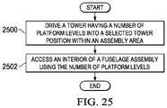
- a method for accessing an interior of a fuselage assemblymay be provided.
- a tower having a number of platform levelsmay be driven into a selected tower position within an assembly area.
- the interior of the fuselage assemblymay be accessed using the number of platform levels.
- an apparatusmay comprise a tower and a vehicle.
- the towermay have a base structure and a number of platform levels associated with the base structure.
- the vehiclemay be physically coupled with the base structure.
- an operator towermay comprise a drivable base structure, a number of platform levels associated with the drivable base structure, a coupling structure associated with the drivable base structure, and a tower coupling unit associated with the drivable base structure.
- a robotics towermay comprise a drivable base structure, a number of platform levels associated with the drivable base structure, a coupling structure associated with the drivable base structure, a tower coupling unit associated with the drivable base structure, a number of internal mobile platforms located on the number of platforms levels, and a number of cable management systems.
- the number of cable management systemsmay be associated with at least one of the drivable base structure or the number of platform levels.
- FIG. 1is an illustration of a manufacturing environment in the form of a block diagram in accordance with an illustrative embodiment
- FIG. 2is an illustration of a fuselage assembly in the form of a block diagram in accordance with an illustrative embodiment
- FIG. 3is an illustration of a plurality of mobile systems of a flexible manufacturing system within a manufacturing environment in the form of a block diagram in accordance with an illustrative embodiment
- FIG. 4is an illustration a plurality of mobile platforms in the form of a block diagram in accordance with an illustrative embodiment
- FIG. 5is an illustration of a flow of a number of utilities across a distributed utility network in the form of a block diagram in accordance with an illustrative embodiment
- FIG. 6is an illustration of a number of towers in the form of a block diagram in accordance with an illustrative embodiment
- FIG. 7is an illustration of an isometric view of a manufacturing environment in accordance with an illustrative embodiment
- FIG. 8is an illustration of a first tower coupled to a utility fixture in accordance with an illustrative embodiment
- FIG. 9is an illustration of an isometric view of a cradle system in accordance with an illustrative embodiment
- FIG. 10is an illustration of an isometric view of an assembly fixture formed using a cradle system and coupled to a first tower in accordance with an illustrative embodiment
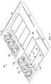
- FIG. 11is an illustration of an isometric view of one stage in the assembly process for building a fuselage assembly that is being supported by an assembly fixture in accordance with an illustrative embodiment
- FIG. 12is an illustration of an isometric view of another stage in the assembly process for building a fuselage assembly in accordance with an illustrative embodiment
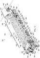
- FIG. 13is an illustration of an isometric view of another stage in the assembly process for building a fuselage assembly being supported by an assembly fixture in accordance with an illustrative embodiment
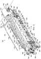
- FIG. 14is an illustration of an isometric view of another stage in the assembly process for building a fuselage assembly in accordance with an illustrative embodiment
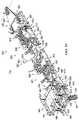
- FIG. 15is an illustration of an isometric view of a second tower coupled to a utility fixture and an assembly fixture supporting a fuselage assembly in accordance with an illustrative embodiment
- FIG. 16is an illustration of an isometric cutaway view of a plurality of mobile platforms performing fastening processes within an interior of a fuselage assembly in accordance with an illustrative embodiment
- FIG. 17is an illustration of a cross-sectional view of a flexible manufacturing system performing operations on a fuselage assembly in accordance with an illustrative embodiment
- FIG. 18is an illustration of an isometric view of a fully built fuselage assembly in accordance with an illustrative embodiment
- FIG. 19is an illustration of an isometric view of fuselage assemblies being built within a manufacturing environment in accordance with an illustrative embodiment
- FIG. 20is an illustration of an enlarged isometric view of a first tower in accordance with an illustrative embodiment
- FIG. 21is an illustration of an isometric view of a first tower coupled to a utility fixture in accordance with an illustrative embodiment
- FIG. 22is an illustration of an enlarged isometric view of a second tower in accordance with an illustrative embodiment
- FIG. 23is an illustration of an isometric view of a second tower without a top platform of the second tower in accordance with an illustrative embodiment
- FIG. 24is an illustration of an internal mobile platform moving inside a fuselage assembly in accordance with an illustrative embodiment
- FIG. 25is an illustration of a process for accessing an interior of a fuselage assembly in the form of a flowchart in accordance with an illustrative embodiment
- FIG. 26is an illustration of a process for accessing an interior of a fuselage assembly using a first tower and a second tower in the form of a flowchart in accordance with an illustrative embodiment
- FIG. 27is an illustration of a process for accessing an interior of a fuselage assembly in the form of a flowchart in accordance with an illustrative embodiment
- FIG. 28is an illustration of a process for accessing an interior of a fuselage assembly in the form of a flowchart in accordance with an illustrative embodiment
- FIG. 29is an illustration of a data processing system in the form of a block diagram in accordance with an illustrative embodiment
- FIG. 30is an illustration of an aircraft manufacturing and service method in the form of a block diagram in accordance with an illustrative embodiment.
- FIG. 31is an illustration of an aircraft in the form of a block diagram in which an illustrative embodiment may be implemented.
- the illustrative embodimentsrecognize and take into account different considerations. For example, the illustrative embodiments recognize and take into account that it may be desirable to automate the process of building a fuselage assembly for an aircraft. Automating the process of building a fuselage assembly for an aircraft may improve build efficiency, improve build quality, and reduce costs associated with building the fuselage assembly. The illustrative embodiments also recognize and take into account that automating the process of building a fuselage assembly may improve the accuracy and precision with which assembly operations are performed, thereby ensuring improved compliance with outer mold line (OML) requirements and inner mold line (IML) requirements for the fuselage assembly.
- OMLouter mold line
- IMLinner mold line
- automating the process used to build a fuselage assembly for an aircraftmay significantly reduce the amount of time needed for the build cycle.
- automating fastening operationsmay reduce and, in some cases, eliminate, the need for human operators to perform these fastening operations as well as other types of assembly operations.
- this type of automation of the process for building a fuselage assembly for an aircraftmay be less labor-intensive, time-consuming, ergonomically challenging, and expensive than performing this process primarily manually. Reduced manual labor may have a desired benefit for the human laborer. Additionally, automating the fuselage assembly process may allow fuselage assemblies to be built in desired assembly facilities and factories at desired assembly rates and desired assembly costs.
- the illustrative embodimentsalso recognize and take into account that it may be desirable to use equipment that can be autonomously driven and operated to automate the process of building a fuselage assembly.
- an autonomous flexible manufacturing systemcomprised of mobile systems that may be autonomously driven across a factory floor, autonomously positioned relative to the factory floor as needed for building the fuselage assembly, autonomously operated to build the fuselage assembly, and then autonomously driven away when building of the fuselage assembly has been completed.
- performing any operation, action, or step autonomouslymay mean performing that operation substantially without any human input.
- a platform that may be autonomously drivenis a platform that may be driven substantially independently of any human input.
- an autonomously drivable platformmay be a platform that is capable of driving or being driven substantially independently of human input.
- the illustrative embodimentsprovide a method, apparatus, and system for building a fuselage assembly for an aircraft.
- the illustrative embodimentsprovide an autonomous flexible manufacturing system that automates most, if not all, of the process of building a fuselage assembly.
- the autonomous flexible manufacturing systemmay automate the process of installing fasteners to join fuselage skin panels and a fuselage support structure together to build the fuselage assembly.
- the illustrative embodimentsrecognize and take into account that automating the process for building a fuselage assembly using an autonomous flexible manufacturing system may present unique technical challenges that require unique technical solutions.
- the illustrative embodimentsrecognize and take into account that it may be desirable to provide utilities to all of the various systems within the autonomous flexible manufacturing system. In particular, it may be desirable to provide these utilities in a manner that will not disrupt or delay the process of building the fuselage assembly or restrict the movement of various mobile systems within the autonomous flexible manufacturing system over a factory floor.
- the infrastructuremay include a utility fixture that provides a direct connection to each of the set of utility sources and an assembly area with a floor space sufficiently large to allow the various systems of an autonomous flexible manufacturing system to be coupled to the utility fixture and each other in series.
- the set of utilitiesmay flow from the set of utility sources to the utility fixture and then downstream to the various systems of the autonomous flexible manufacturing system within the assembly area.
- the illustrative embodimentsprovide a distributed utility network that may be used to provide utilities to the various systems of the autonomous flexible manufacturing system.
- the distributed utility networkmay provide these utilities in a manner that does not restrict or impede movement of the various mobile systems of the autonomous flexible manufacturing system.
- the different mobile systems of the autonomous flexible manufacturing systemmay be autonomously coupled to each other to create this distributed utility network.
- the illustrative embodimentsrecognize and take into account that it may be desirable to have an apparatus and method for accessing an interior of a fuselage assembly easily and in a safe manner.
- the illustrative embodimentsrecognize and take into account that using a tower having a number of platform levels that can be mated with a number of floors of the fuselage assembly may improve the ease with which a human operator or mobile platforms comprising robotic devices may be moved into the interior of the fuselage assembly.
- the illustrative embodimentsprovide an operator tower and a robotic tower that may be used to access the interior of a fuselage assembly.
- FIGS. 1 - 6illustrations of a manufacturing environment are depicted in the form of block diagrams in accordance with an illustrative embodiment.
- a fuselage assemblya flexible manufacturing system
- the various systems within the flexible manufacturing system that may be used to build the fuselage assemblyand a distributed utility network are described.
- manufacturing environment 100may be an example of one environment in which at least a portion of fuselage 102 may be manufactured for aircraft 104 .
- Manufacturing environment 100may take a number of different forms.
- manufacturing environment 100may take the form of a factory, a manufacturing facility, an outdoor factory area, an enclosed manufacturing area, an offshore platform, or some other type of manufacturing environment 100 suitable for building at least a portion of fuselage 102 .
- Fuselage 102may be built using manufacturing process 108 .
- Flexible manufacturing system 106may be used to implement at least a portion of manufacturing process 108 .
- manufacturing process 108may be substantially automated using flexible manufacturing system 106 .
- only one or more stages of manufacturing process 108may be substantially automated.
- Flexible manufacturing system 106may be configured to perform at least a portion of manufacturing process 108 autonomously. In this manner, flexible manufacturing system 106 may be referred to as autonomous flexible manufacturing system 112 . In other illustrative examples, flexible manufacturing system 106 may be referred to as an automated flexible manufacturing system.
- manufacturing process 108may include assembly process 110 for building fuselage assembly 114 .
- Flexible manufacturing system 106may be configured to perform at least a portion of assembly process 110 autonomously.
- Fuselage assembly 114may be fuselage 102 at any stage during manufacturing process 108 prior to the completion of manufacturing process 108 .
- fuselage assembly 114may be used to refer to a partially assembled fuselage 102 .
- one or more other componentsmay need to be attached to fuselage assembly 114 to fully complete the assembly of fuselage 102 .
- fuselage assembly 114may be used to refer to the fully assembled fuselage 102 .
- Flexible manufacturing system 106may build fuselage assembly 114 up to the point needed to move fuselage assembly 114 to a next stage in the manufacturing process for building aircraft 104 .
- at least a portion of flexible manufacturing system 106may be used at one or more later stages in the manufacturing process for building aircraft 104 .
- fuselage assembly 114may be an assembly for forming a particular section of fuselage 102 .
- fuselage assembly 114may take the form of aft fuselage assembly 116 for forming an aft section of fuselage 102 .
- fuselage assembly 114may take the form of forward fuselage assembly 117 for forming a forward section of fuselage 102 .
- fuselage assembly 114may take the form of middle fuselage assembly 118 for forming a center section of fuselage 102 or some other middle section of fuselage 102 between the aft and forward sections of fuselage 102 .
- fuselage assembly 114may include plurality of panels 120 and support structure 121 .
- Support structure 121may be comprised of plurality of members 122 .
- Plurality of members 122may be used to both support plurality of panels 120 and connect plurality of panels 120 to each other.
- Support structure 121may help provide strength, stiffness, and load support for fuselage assembly 114 .
- Plurality of members 122may be associated with plurality of panels 120 .
- associationis a physical association in the depicted examples.
- a first componentsuch as one of plurality of members 122
- a second componentsuch as one of plurality of panels 120
- the first componentalso may be connected to the second component using one or more other components.
- the first componentmay be connected to the second component using a third component.
- the first componentmay be considered to be associated with the second component by being formed as part of the second component, an extension of the second component, or both.
- the first componentmay be considered part of the second component by being co-cured with the second component.
- the phrase “at least one of,” when used with a list of items,means different combinations of one or more of the listed items may be used and only one of the items in the list may be needed.
- the itemmay be a particular object, thing, action, process, or category.
- “at least one of”means any combination of items or number of items may be used from the list, but not all of the items in the list may be required.
- “at least one of item A, item B, and item C” or “at least one of item A, item B, or item C”may mean item A; item A and item B; item B; item A, item B, and item C; or item B and item C.
- “at least one of item A, item B, and item C”may mean, for example, without limitation, two of item A, one of item B, and ten of item C; four of item B and seven of item C; or some other suitable combination.
- a member of plurality of members 122may be associated with at least one of plurality of panels 120 in a number of different ways.
- a member of plurality of members 122may be attached directly to a single panel, attached to two or more panels, attached to another member that is directly attached to at least one panel, attached to at least one member that is directly or indirectly attached to at least one panel, or associated with at least one of plurality of panels 120 in some other way.
- substantially all or all of plurality of members 122may be associated with plurality of panels 120 prior to the beginning of assembly process 110 for building fuselage assembly 114 .
- a corresponding portion of plurality of members 122may be associated with each panel of plurality of panels 120 prior to plurality of panels 120 being joined to each other through assembly process 110 .
- Assembly process 110may include attaching a remaining portion of plurality of members 122 to plurality of panels 120 for at least one of providing support to plurality of panels 120 or connecting plurality of panels 120 together.
- the first portion of plurality of members 122 attached to plurality of panels 120 prior to assembly process 110 and the remaining portion of plurality of members 122 attached to plurality of panels 120 during assembly process 110may together form support structure 121 .
- all of plurality of members 122may be associated with plurality of panels 120 during assembly process 110 .
- each of plurality of panels 120may be “naked” without any members attached to or otherwise associated with the panel prior to assembly process 110 .
- plurality of members 122may then be associated with plurality of panels 120 .
- support structure 121 for fuselage assembly 114may be built up in a number of different ways.
- Fuselage assembly 114 comprising plurality of panels 120 and support structure 121is described in greater detail in FIG. 2 below.
- Building fuselage assembly 114may include joining plurality of panels 120 together.
- Joining plurality of panels 120may be performed in a number of different ways.
- joining plurality of panels 120 togethermay include joining one or more of plurality of members 122 to one or more of plurality of panels 120 or to other members of plurality of members 122 .
- joining plurality of panels 120may include joining at least one panel to at least one other panel, joining at least one member to at least one other member, or joining at least one member to at least one panel, or some combination thereof.
- joining a first panel and a second panel togethermay include at least one of the following: fastening the first panel directly to the second panel, joining a first member associated with the first panel to a second member associated with the second panel, joining a member associated with the first panel directly to the second panel, joining one member associated with both the first panel and the second panel to another member, joining a selected member to both the first panel and the second panel, or some other type of joining operation.
- Assembly process 110may include operations 124 that may be performed to join plurality of panels 120 together to build fuselage assembly 114 .
- flexible manufacturing system 106may be used to perform at least a portion of operations 124 autonomously.
- Operations 124may include, for example, but are not limited to, temporary connection operations 125 , drilling operations 126 , fastener insertion operations 128 , fastener installation operations 130 , inspection operations 132 , other types of assembly operations, or some combination thereof.
- Temporary connection operations 125may be performed to temporarily connect plurality of panels 120 together.
- temporary connection operations 125may include temporarily tacking plurality of panels 120 together using tack fasteners.
- Drilling operations 126may include drilling holes through one or more of plurality of panels 120 and, in some cases, through one or more of plurality of members 122 .
- Fastener insertion operations 128may include inserting fasteners into the holes drilled by drilling operations 126 .
- Fastener installation operations 130may include fully installing each of the fasteners that have been inserted into the holes.
- Fastener installation operations 130may include, for example, without limitation, riveting operations, interference-fit bolting operations, other types of fastener installation operations, or some combination thereof.
- Inspection operations 132may include inspecting the fully installed fasteners.
- flexible manufacturing system 106may be used to perform any number of these different types of operations 124 substantially autonomously.
- flexible manufacturing system 106may include plurality of mobile systems 134 , control system 136 , and utility system 138 .
- Each of plurality of mobile systems 134may be a drivable mobile system.
- each of plurality of mobile systems 134may be an autonomously drivable mobile system.
- each of plurality of mobile systems 134may include one or more components that may be autonomously driven within manufacturing environment 100 from one location to another location. Plurality of mobile systems 134 are described in greater detail in FIG. 3 below.
- control system 136may be used to control the operation of flexible manufacturing system 106 .
- control system 136may be used to control plurality of mobile systems 134 .
- control system 136may be used to direct the movement of each of plurality of mobile systems 134 within manufacturing environment 100 .
- Control system 136may be at least partially associated with plurality of mobile systems 134 .
- control system 136may include set of controllers 140 .
- a “set of” itemsmay include one or more items.
- set of controllers 140may include one or more controllers.
- Each of set of controllers 140may be implemented using hardware, firmware, software, or some combination thereof.
- set of controllers 140may be associated with plurality of mobile systems 134 .
- one or more of set of controllers 140may be implemented as part of plurality of mobile systems 134 .
- one or more of set of controllers 140may be implemented independently of plurality of mobile systems 134 .
- Set of controllers 140may generate commands 142 to control the operation of plurality of mobile systems 134 of flexible manufacturing system 106 .
- Set of controllers 140may communicate with plurality of mobile systems 134 using at least one of a wireless communications link, a wired communications link, an optical communications link, or other type of communications link. In this manner, any number of different types of communications links may be used for communication with and between set of controllers 140 .
- control system 136may control the operation of plurality of mobile systems 134 using data 141 received from sensor system 133 .
- Sensor system 133may be comprised of any number of individual sensor systems, sensor devices, controllers, other types of components, or combination thereof.
- sensor system 133may include laser tracking system 135 and radar system 137 .
- Laser tracking system 135may be comprised of any number of laser tracking devices, laser targets, or combination thereof.
- Radar system 137may be comprised of any number of radar sensors, radar targets, or combination thereof.
- Sensor system 133may be used to coordinate the movement and operation of the various mobile systems in plurality of mobile systems 134 within manufacturing environment 100 .
- radar system 137may be used for macro-positioning mobile systems, systems within mobile systems, components within mobile systems, or some combination thereof.
- laser tracking system 135may be used for micro-positioning mobile systems, systems within mobile systems, components within mobile systems, or some combination thereof.
- Plurality of mobile systems 134may be used to form distributed utility network 144 .
- one or more of plurality of mobile systems 134may form distributed utility network 144 .
- Number of utilities 146may flow from number of utility sources 148 to the various mobile systems of plurality of mobile systems 134 that make up distributed utility network 144 .
- each of number of utility sources 148may be located with manufacturing environment 100 .
- one or more of number of utility sources 148may be located outside of manufacturing environment 100 .
- the corresponding utility provided by these one or more utility sourcesmay then be carried into manufacturing environment 100 using, for example, without limitation, one or more utility cables.
- distributed utility network 144may allow number of utilities 146 to flow directly from number of utility sources 148 to one mobile system in plurality of mobile systems 134 over some number of utility cables. This one mobile system may then distribute number of utilities 146 to other mobile systems of plurality of mobile systems 134 such that these other mobile systems do not need to directly receive number of utilities 146 from number of utility sources 148 .
- Utility system 138may include utility fixture 150 .
- Utility system 138may be configured to connect to number of utility sources 148 such that number of utilities 146 may flow from number of utility sources 148 to utility fixture 150 .
- Utility fixture 150may be above-ground or in-ground, depending on the implementation.
- utility fixture 150may be embedded in a floor within manufacturing environment 100 .
- Utility fixture 150may then distribute number of utilities 146 to one or more of plurality of mobile systems 134 .
- one autonomous coupling of one of plurality of mobile systems 134 to utility fixture 150may be followed by any number of autonomous couplings of mobile systems to each other in series to form distributed utility network 144 .
- Utility fixture 150may distribute number of utilities 146 to each of plurality of mobile systems 134 downstream of utility fixture 150 in the series of autonomous couplings of the mobile systems.
- distributed utility network 144may have a chain-like configuration or a tree-like configuration.
- plurality of mobile systems 134may include mobile systems A, B, C, and D (not shown in figure) with mobile system A autonomously coupled to utility fixture 150 and mobile systems B, C, and D autonomously coupled to mobile system A and each other in series.
- An example of a chain-like configuration for distributed utility network 144may include number of utilities 146 flowing from number of utility sources 148 over some number of utility cables to utility fixture 150 , from utility fixture 150 to mobile system A, from mobile system A to mobile system B, from mobile system B to mobile system C, and from mobile system C to mobile system D.
- An example of a tree-like configuration for distributed utility network 144may include number of utilities 146 flowing from number of utility sources 148 over some number of utility cables to utility fixture 150 , from utility fixture 150 to mobile system A, from mobile system A to both mobile system B and mobile system C, and from mobile system C to mobile system D.
- An example of one manner in which distributed utility network 144 may be implemented using plurality of mobile systems 134is described in greater detail in FIG. 5 below.
- multiple flexible manufacturing systemsmay be used to build multiple fuselage assemblies concurrently.
- flexible manufacturing system 106may be a first flexible manufacturing system of many flexible manufacturing systems.
- flexible manufacturing system 106 , second flexible manufacturing system 152 , and third flexible manufacturing system 154may be used to build aft fuselage assembly 116 , middle fuselage assembly 118 , and forward fuselage assembly 117 , respectively. Aft fuselage assembly 116 , middle fuselage assembly 118 , and forward fuselage assembly 117 may then be joined together to form a fully assembled fuselage 102 . In this manner, in this example, flexible manufacturing system 106 , second flexible manufacturing system 152 , and third flexible manufacturing system 154 may together form flexible fuselage manufacturing system 158 .
- any number of fuselage assembliessuch as fuselage assembly 114
- fuselage assembly 114may be built within manufacturing environment 100 using any number of flexible manufacturing systems implemented in a manner similar to flexible manufacturing system 106 .
- any number of full fuselagessuch as fuselage 102
- fuselage manufacturing system 158may be built within manufacturing environment 100 using any number of flexible fuselage manufacturing systems implemented in a manner similar to flexible fuselage manufacturing system 158 .
- fuselage assembly 114may include plurality of panels 120 and support structure 121 .
- Fuselage assembly 114may be used to refer to any stage in the building of fuselage assembly 114 .
- fuselage assembly 114may be used to refer to a single one of plurality of panels 120 , multiple ones of plurality of panels 120 that have been or are being joined together, a partially built fuselage assembly, or a fully built fuselage assembly.
- fuselage assembly 114may be built such that fuselage assembly 114 has plurality of fuselage sections 205 .
- Each of plurality of fuselage sections 205may include one or more of plurality of panels 120 .
- each of plurality of fuselage sections 205may take the form of a cylindrically-shaped fuselage section, a barrel-shaped fuselage section, a tapered cylindrical fuselage section, a cone-shaped fuselage section, a dome-shaped fuselage section, or a section having some other type of shape.
- a fuselage section of plurality of fuselage sections 205may have a shape that has a substantially circular cross-sectional shape, elliptical cross-sectional shape, oval cross-sectional shape, polygon with rounded corners cross-sectional shape, or otherwise closed-curve cross-sectional shape.
- each of plurality of fuselage sections 205may be a portion of fuselage assembly 114 defined between two radial cross-sections of fuselage assembly 114 that are taken substantially perpendicular to a center axis or longitudinal axis through fuselage assembly 114 . In this manner, plurality of fuselage sections 205 may be arranged along the longitudinal axis of fuselage assembly 114 . In other words, plurality of fuselage sections 205 may be arranged longitudinally.
- Fuselage section 207may be an example of one of plurality of fuselage sections 205 .
- Fuselage section 207may be comprised of one or more of plurality of panels 120 .
- multiple panel sectionsmay be arranged circumferentially around fuselage section 207 to form the skin of fuselage section 207 .
- multiple rows of two or more longitudinally adjacent panelsmay be arranged circumferentially around fuselage section 207 to form the skin of fuselage section 207 .
- fuselage assembly 114may have crown 200 , keel 202 , and sides 204 .
- Sides 204may include first side 206 and second side 208 .
- Crown 200may be the top portion of fuselage assembly 114 .
- Keel 202may be the bottom portion of fuselage assembly 114 .
- Sides 204 of fuselage assembly 114may be the portions of fuselage assembly 114 between crown 200 and keel 202 .
- each of crown 200 , keel 202 , first side 206 , and second side 208 of fuselage assembly 114may be formed by at least a portion of at least one of plurality of panels 120 . Further, a portion of each of plurality of fuselage sections 205 may form each of crown 200 , keel 202 , first side 206 , and second side 208 .
- Panel 216may be an example of one of plurality of panels 120 .
- Panel 216may also be referred to as a skin panel, a fuselage panel, or a fuselage skin panel, depending on the implementation.
- panel 216may take the form of a mega-panel comprised of multiple smaller panels, which may be referred to as sub-panels.
- a mega-panelmay also be referred to as a super panel.
- panel 216may be comprised of at least one of a metal, a metal alloy, some other type of metallic material, a composite material, or some other type of material.
- panel 216may be comprised of an aluminum alloy, steel, titanium, a ceramic material, a composite material, some other type of material, or some combination thereof.
- panel 216When used to form keel 202 of fuselage assembly 114 , panel 216 may be referred to as a keel panel or a bottom panel. When used to form one of sides 204 of fuselage assembly 114 , panel 216 may be referred to as a side panel. When used to form crown 200 of fuselage assembly 114 , panel 216 may be referred to as a crown panel or a top panel. As one illustrative example, plurality of panels 120 may include crown panels 218 for forming crown 200 , side panels 220 for forming sides 204 , and keel panels 222 for forming keel 202 . Side panels 220 may include first side panels 224 for forming first side 206 and second side panels 226 for forming second side 208 .
- fuselage section 207 of plurality of fuselage sections 205 of fuselage assembly 114may include one of crown panels 218 , two of side panels 220 , and one of keel panels 222 . In another illustrative example, fuselage section 207 may form an end of fuselage assembly 114 .
- fuselage section 207may be comprised solely of a single panel, such as panel 216 .
- panel 216may take the form of end panel 228 .
- End panel 228may be used to form one end of fuselage assembly 114 .
- end panel 228may form the aftmost end of fuselage assembly 114 .
- end panel 228may form the forwardmost end of fuselage assembly 114 .
- end panel 228may take the form of a cylindrically-shaped panel, a cone-shaped panel, a barrel-shaped panel, or a tapered cylindrical panel.
- end panel 228may be a single cylindrically-shaped panel having a substantially circular cross-sectional shape that may change in diameter with respect to a center axis for fuselage assembly 114 .
- fuselage section 207may be comprised solely of end panel 228 .
- fuselage section 207may be an end fuselage section that is comprised of only a single panel, which may be end panel 228 .
- bulkhead 272may be associated with end panel 228 when fuselage section 207 is an end fuselage section.
- Bulkhead 272which may also be referred to as a pressure bulkhead, may be considered separate from or part of end panel 228 , depending on the implementation. Bulkhead 272 may have a dome-type shape in these illustrative examples.
- bulkhead 272may be part of fuselage section 207 located at the aftmost end of aft fuselage assembly 116 .
- bulkhead 272may be part of fuselage section 207 located at forwardmost end of aft fuselage assembly 116 .
- Middle fuselage assembly 118 in FIG. 1may not include a bulkhead, such as bulkhead 272 , at either end of middle fuselage assembly 118 . In this manner, plurality of fuselage sections 205 may be implemented in any number of different ways.
- Panel 216may have first surface 230 and second surface 232 .
- First surface 230may be configured for use as an exterior-facing surface. In other words, first surface 230 may be used to form exterior 234 of fuselage assembly 114 .
- Second surface 232may be configured for use as an interior-facing surface. In other words, second surface 232 may be used to form interior 236 of fuselage assembly 114 .
- Each of plurality of panels 120may be implemented in a manner similar to panel 216 .
- support structure 121may be associated with a corresponding one of plurality of panels 120 .
- Support structure 121may be comprised of plurality of members 122 that are associated with panel 216 .
- corresponding portion 240may be the portion of plurality of members 122 that correspond to panel 216 .
- Corresponding portion 240may form support section 238 corresponding to panel 216 .
- Support section 238may form a part of support structure 121 .
- Plurality of members 122may include support members 242 .
- Support members 242may include, for example, without limitation, at least one of connecting members 244 , frames 246 , stringers 248 , stiffeners 250 , stanchions 252 , intercostal structural members 254 , or other types of structural members.
- Connecting members 244may connect other types of support members 242 together. In some cases, connecting members 244 may also connect support members 242 to plurality of panels 120 . Connecting members 244 may include, for example, without limitation, shear clips 256 , ties 258 , splices 260 , intercostal connecting members 262 , other types of mechanical connecting members, or some combination thereof.
- connecting members 244may be used to, for example, without limitation, connect together complementary frames of frames 246 running in the hoop-wise direction on adjacent sub-panels and complementary stringers of stringers 248 running in the longitudinal direction on adjacent sub-panels.
- connecting members 244may be used to connect together complementary frames, stringers, or other types of support members on two or more adjacent panels in plurality of panels 120 .
- connecting members 244may be used to connect together complementary support members on two or more adjacent fuselage sections.
- Operations 124may be performed to join plurality of panels 120 together to build fuselage assembly 114 .
- plurality of fasteners 264may be used to join plurality of panels 120 together.
- joining plurality of panels 120 togethermay be performed in a number of different ways.
- Joining plurality of panels 120 togethermay include at least one of joining at least one panel in plurality of panels 120 to another one of plurality of panels 120 , joining at least one panel in plurality of panels 120 to at least one of plurality of members 122 , joining at least one member in plurality of members 122 to another one of plurality of members 122 , or some other type of joining operation.
- Plurality of panels 120may be joined together such that plurality of members 122 ultimately form support structure 121 for fuselage assembly 114 .
- number of floors 266may be associated with fuselage assembly 114 .
- number of floors 266may be part of fuselage assembly 114 .
- Number of floors 266may include, for example, without limitation, at least one of a passenger floor, a cargo floor, or some other type of floor.
- FIG. 3an illustration of plurality of mobile systems 134 of flexible manufacturing system 106 within manufacturing environment 100 from FIG. 1 is depicted in the form of a block diagram in accordance with an illustrative embodiment.
- flexible manufacturing system 106may be used to build fuselage assembly 114 on floor 300 of manufacturing environment 100 .
- floor 300may be referred to as factory floor 302 .
- floor 300may be substantially smooth and substantially planar.
- floor 300may be substantially level.
- one or more portions of floor 300may be sloped, ramped, or otherwise uneven.
- Assembly area 304may be an area within manufacturing environment 100 designated for performing assembly process 110 in FIG. 1 to build a fuselage assembly, such as fuselage assembly 114 .
- Assembly area 304may also be referred to as a cell or a work cell.
- assembly area 304may be a designated area on floor 300 .
- assembly area 304may include a designated area on floor 300 as well as the area above this designated area. Any number of assembly areas may be present within manufacturing environment 100 such that any number of fuselage assemblies may be built concurrently within manufacturing environment 100 .
- plurality of mobile systems 134may include plurality of autonomous vehicles 306 , cradle system 308 , tower system 310 , and autonomous tooling system 312 .
- Each of plurality of mobile systems 134may be drivable across floor 300 .
- each of plurality of mobile systems 134may be capable of being autonomously driven across floor 300 from one location 315 to another location 317 on floor 300 .
- each of plurality of autonomous vehicles 306may take the form of an automated guided vehicle (AGV), which may be capable of operating independently without human direction or guidance.
- AGVautomated guided vehicle
- plurality of autonomous vehicles 306may be referred to as a plurality of automated guided vehicles (AGVs).
- cradle system 308may be used to support and hold fuselage assembly 114 during assembly process 110 in FIG. 1 .
- cradle system 308may be referred to as a drivable cradle system.
- cradle system 308may be referred to as an autonomously drivable cradle system.
- Cradle system 308may include number of fixtures 313 .
- a “number of” itemsmay include one or more items.
- number of fixtures 313may include one or more fixtures.
- number of fixtures 313may be referred to as a number of drivable fixtures.
- number of fixtures 313may be referred to as a number of autonomously drivable fixtures.
- Number of fixtures 313may include number of cradle fixtures 314 .
- number of cradle fixtures 314may be referred to as a number of drivable cradle fixtures.
- number of cradle fixtures 314may be referred to as a number of autonomously drivable cradle fixtures.
- Cradle fixture 322may be an example of one of number of cradle fixtures 314 .
- Number of retaining structures 326may be associated with each of number of cradle fixtures 314 .
- Number of retaining structures 326 associated with each of number of cradle fixtures 314may be engaged with and used to support fuselage assembly 114 .
- number of retaining structures 326 associated with cradle fixture 322may be engaged with and used to support one or more of plurality of panels 120 .
- Number of cradle fixtures 314may be autonomously driven across floor 300 of manufacturing environment 100 to assembly area 304 .
- each of number of cradle fixtures 314may be autonomously driven across floor 300 using a corresponding one of plurality of autonomous vehicles 306 .
- number of corresponding autonomous vehicles 316 in plurality of autonomous vehicles 306may be used to drive number of cradle fixtures 314 across floor 300 into assembly area 304 .
- number of corresponding autonomous vehicles 316may drive from, for example, without limitation, holding area 318 , across floor 300 , to assembly area 304 .
- Holding area 318may be an area in which at least one of plurality of autonomous vehicles 306 , cradle system 308 , tower system 310 , autonomous tooling system 312 , or control system 136 from FIG. 1 may be held when flexible manufacturing system 106 is not in use or when that particular device or system is not in use.
- Holding area 318may be referred to as a home area, a storage area, or a base area, depending on the implementation. Although holding area 318 is depicted as being located within manufacturing environment 100 , holding area 318 may be located in some other area or environment outside of manufacturing environment 100 in other illustrative examples.
- Number of corresponding autonomous vehicles 316 in plurality of autonomous vehicles 306may drive number of cradle fixtures 314 into number of selected cradle positions 320 .
- a “position”may be comprised of a location, an orientation, or both.
- the locationmay be in two-dimensional coordinates or three-dimensional coordinates with respect to a reference coordinate system.
- the orientationmay be a two-dimensional or three-dimensional orientation with respect to a reference coordinate system.
- This reference coordinate systemmay be, for example, without limitation, a fuselage coordinate system, an aircraft coordinate system, a coordinate system for manufacturing environment 100 , or some other type of coordinate system.
- cradle fixtures 314When number of cradle fixtures 314 includes more than one cradle fixture such that number of selected cradle positions 320 includes more than one cradle position, these cradle positions may be positions selected relative to each other. In this manner, number of cradle fixtures 314 may be positioned such that number of cradle fixtures 314 are in number of selected cradle positions 320 relative to each other.
- number of corresponding autonomous vehicles 316may be used to drive number of cradle fixtures 314 into number of selected cradle positions 320 within assembly area 304 .
- “Driving” a component or a system across floor 300may mean, for example, but not limited to, moving substantially the entirety of that component or system from one location to another location.
- driving cradle fixture 322 across floor 300may mean moving the entirety of cradle fixture 322 from one location to another location.
- all or substantially all components that comprise cradle fixture 322may be simultaneously moved together from one location to another location.
- number of cradle fixtures 314may be coupled to each other and to tower system 310 .
- Number of corresponding autonomous vehicles 316may then drive away from number of cradle fixtures 314 to, for example, without limitation, holding area 318 , once number of cradle fixtures 314 is positioned in number of selected cradle positions 320 within selected tolerances.
- number of corresponding autonomous vehicles 316may be comprised of a single autonomous vehicle that is used to drive each of number of cradle fixtures 314 into a corresponding selected position in number of selected cradle positions 320 within assembly area 304 one at a time.
- number of cradle fixtures 314may be configured to form assembly fixture 324 .
- Assembly fixture 324may be formed when the different cradle fixtures in number of cradle fixtures 314 have been placed in number of selected cradle positions 320 relative to each other. In some cases, assembly fixture 324 may be formed when number of cradle fixtures 314 have been coupled to each other while number of cradle fixtures 314 is in number of selected cradle positions 320 and when number of retaining structures 326 associated with each of number of cradle fixtures 314 has been adjusted to receive fuselage assembly 114 .
- assembly fixture 324may be used to support and hold fuselage assembly 114 .
- assembly fixture 324may be referred to as an assembly fixture system or a fixture system.
- assembly fixture 324may be referred to as a drivable assembly fixture.
- assembly fixture 324may be referred to as an autonomously drivable assembly fixture.
- number of cradle fixtures 314may receive fuselage assembly 114 .
- plurality of fuselage sections 205may be engaged with number of cradle fixtures 314 .
- plurality of fuselage sections 205may be engaged with number of retaining structures 326 associated with each of number of cradle fixtures 314 .
- Plurality of fuselage sections 205may be engaged with number of cradle fixtures 314 in any number of ways.
- each cradle fixturemay be used to support and hold substantially the entire fuselage assembly 114 .
- each of these cradle fixturesmay be used to support and hold at least one corresponding fuselage section of plurality of fuselage sections 205 .
- each of plurality of fuselage sections 205may be engaged with number of cradle fixtures 314 one at a time.
- all of the panels for a particular fuselage section in plurality of fuselage sections 205may be positioned relative to each other and a corresponding cradle fixture in number of cradle fixtures 314 and then engaged with the corresponding cradle fixture.
- the remaining fuselage sections in plurality of fuselage sections 205may then be formed and engaged with number of cradle fixtures 314 in a similar manner.
- plurality of panels 120may be engaged with number of cradle fixtures 314 by engaging at least a portion of plurality of panels 120 with number of retaining structures 326 associated with each of number of cradle fixtures 314 that makes up assembly fixture 324 such that plurality of panels 120 is supported by number of cradle fixtures 314 .
- plurality of panels 120may include keel panels 222 , side panels 220 , and crown panels 218 .
- all of keel panels 222 in FIG. 2 used to form keel 202 of fuselage assembly 114 in FIG. 2may first be positioned relative to and engaged with number of cradle fixtures 314 .
- all of side panels 220 in FIG. 2 used to form sides 204 of fuselage assembly 114 in FIG. 2may be positioned relative to and engaged with keel panels 222 .
- all of crown panels 218 in FIG. 2 used to form crown 200 of fuselage assembly 114 in FIG. 2may be positioned relative to and engaged with side panels 220 .
- plurality of fuselage sections 205may be concurrently assembled to form fuselage assembly 114 .
- each panel in plurality of panels 120may have a corresponding portion of plurality of members 122 fully formed and associated with the panel prior to the panel being engaged with one of number of cradle fixtures 314 .
- This corresponding portion of plurality of members 122may be referred to as a support section.
- support section 238 in FIG. 2may be fully formed and associated with panel 216 in FIG. 2 prior to panel 216 being engaged with one of number of cradle fixtures 314 or another panel of plurality of panels 120 in FIG. 2 .
- a corresponding portion of support members 242 in FIG. 2may already be attached to panel 216 and a corresponding portion of connecting members 244 in FIG. 2 already installed to connect this portion of support members 242 to each other prior to panel 216 from FIG. 2 being engaged with one of number of cradle fixtures 314 .
- plurality of members 122may be associated with plurality of panels 120 after plurality of panels 120 have been engaged with each other and number of cradle fixtures 314 . In still other illustrative examples, only a portion of plurality of members 122 may be associated with plurality of panels 120 prior to plurality of panels 120 being engaged with each other and number of cradle fixtures 314 and then a remaining portion of plurality of members 122 associated with plurality of panels 120 once plurality of panels 120 have been engaged with each other and number of cradle fixtures 314 .
- one or more of support members 242 in FIG. 2 , one or more of connecting members 244 in FIG. 2 , or bothmay not be associated with panel 216 when panel 216 from FIG. 2 is engaged with one of number of cradle fixtures 314 or with one of the other panels in plurality of panels 120 .
- frames 246 described in FIG. 2may be added to panel 216 from FIG. 2 after panel 216 has been engaged with cradle fixture 322 .
- stiffeners 250 described in FIG. 2may be added to panel 216 from FIG. 2 after panel 216 has been engaged with cradle fixture 322 .
- Building fuselage assembly 114may include engaging plurality of panels 120 with each other as plurality of panels 120 are built up on number of cradle fixtures 314 of assembly fixture 324 .
- adjacent panels in plurality of panels 120may be connected by connecting at least a portion of the support members associated with the panels.
- at least one of lap splices, butt splices, or other types of splicesmay be used to connect the adjacent panels in addition to or in place of connecting the corresponding support members of the adjacent panels.
- the support members associated with two adjacent panels in plurality of panels 120may be connected together using connecting members, thereby connecting the two adjacent panels.
- the two support members associated with these two adjacent panelsmay be, for example, without limitation, spliced, tied, clipped, tacked, pinned, joined, or fastened together in some other manner.
- complementary framesmay be connected in the hoop-wise direction.
- complementary stringersmay be connected in the longitudinal direction.
- connecting complementary stringers, frames, or other support members on these two adjacent panelsmay be part of splicing these panels together.
- Adjacent panelsmay be connected together using any number of panel splices, stringer splices, frame splices, or other types of splices.
- plurality of panels 120may be temporarily connected to each other by temporarily fastening at least one of plurality of panels 120 or plurality of members 122 together using temporary fasteners or permanent fasteners.
- temporary clampsmay be used to temporarily connect and hold in place two of plurality of panels 120 together.
- Temporarily connecting plurality of panels 120 togethermay be performed by at least one of temporarily connecting at least two plurality of panels 120 together, temporarily connecting at least two plurality of members 122 together, or temporarily connecting at least one of plurality of panels 120 to at least one of plurality of members 122 such that plurality of members 122 associated with plurality of panels 120 forms support structure 121 in FIG. 2 for fuselage assembly 114 .
- plurality of panels 120may be temporarily tacked or pinned together using temporary fasteners 328 until plurality of fasteners 264 are installed to join plurality of panels 120 together to form fuselage assembly 114 .
- Temporarily connecting plurality of panels 120may temporarily connect together plurality of fuselage sections 205 from FIG. 2 formed by plurality of panels 120 .
- temporary fasteners 328may then be removed.
- plurality of panels 120may be connected together in a number of different ways. Once plurality of panels 120 have been connected together, plurality of members 122 may be considered as forming support structure 121 for fuselage assembly 114 . Connecting plurality of panels 120 together and forming support structure 121 may maintain desired compliance with outer mold line requirements and inner mold line requirements for fuselage assembly 114 . In other words, plurality of panels 120 may be held together in place relative to each other such that fuselage assembly 114 formed using plurality of panels 120 meets outer mold line requirements and inner mold line requirements for fuselage assembly 114 within selected tolerances.
- assembly fixture 324may support plurality of panels 120 and support structure 121 associated with plurality of panels 120 such that fuselage assembly 114 built using plurality of panels 120 and support structure 121 has a shape and a configuration that is within selected tolerances. In this manner, this shape and configuration may be maintained within selected tolerances while supporting plurality of panels 120 and plurality of members 122 associated with plurality of panels 120 during the building of fuselage assembly 114 .
- This shapemay be at least partially determined by, for example, without limitation, the outer mold line requirements and inner mold line requirements for fuselage assembly 114 . In some cases, the shape may be at least partially determined by the location and orientation of the frames and stringers of fuselage assembly 114 .
- number of corresponding autonomous vehicles 316may drive assembly fixture 324 out of assembly area 304 .
- fuselage assembly 114may be driven across floor 300 into a different area within manufacturing environment 100 , from floor 300 onto another floor in a different manufacturing environment, or from floor 300 onto another floor in some other area or environment.
- assembly fixture 324may be driven to some other location at which another assembly fixture is located such that the two assembly fixtures may be coupled to form a larger assembly fixture.
- assembly fixture 324may be used to hold and support aft fuselage assembly 116 in FIG. 1
- another assembly fixture implemented in a manner similar to assembly fixture 324may be used to hold and support forward fuselage assembly 117 in FIG. 1
- Yet another assembly fixture implemented in a manner similar to assembly fixture 324may be used to hold and support middle fuselage assembly 118 in FIG. 1 .
- the three assembly fixturesmay be brought together to form a larger assembly fixture for holding aft fuselage assembly 116 , middle fuselage assembly 118 , and forward fuselage assembly 117 such that these three fuselage assemblies may be joined to form fuselage 102 described in FIG. 1 .
- this larger assembly fixturemay hold aft fuselage assembly 116 , middle fuselage assembly 118 , and forward fuselage assembly 117 in alignment with each other such that fuselage 102 may be built within selected tolerances.
- a first assembly fixture and a second assembly fixture implemented in a manner similar to assembly fixture 324may be used to hold and support aft fuselage assembly 116 and forward fuselage assembly 117 , respectively, from FIG. 1 .
- the two assembly fixturesmay then be brought together to form a larger assembly fixture for holding the two fuselage assemblies such that these fuselage assemblies may be joined to form fuselage 102 .
- the larger assembly fixturemay hold aft fuselage assembly 116 and forward fuselage assembly 117 in alignment with each other such that fuselage 102 may be built within selected tolerances.
- tower system 310includes number of towers 330 .
- Tower 332may be an example of one implementation for one of number of towers 330 .
- Tower 332may be configured to provide access to interior 236 of fuselage assembly 114 described in FIG. 2 .
- tower 332may be referred to as a drivable tower.
- tower 332may be referred to as an autonomously drivable tower.
- tower 332may take the form of first tower 334 .
- First tower 334may also be referred to as an operator tower in some cases.
- tower 332may take the form of second tower 336 .
- Second tower 336may also be referred to as a robotics tower in some cases.
- number of towers 330may include both first tower 334 and second tower 336 .
- First tower 334may be configured substantially for use by a human operator, whereas second tower 336 may be configured substantially for use by a mobile platform having at least one robotic device associated with the mobile platform.
- first tower 334may allow a human operator to access and enter interior 236 of fuselage assembly 114 .
- Second tower 336may allow a mobile platform to access and enter interior 236 of fuselage assembly 114 .
- First tower 334 and second tower 336may be positioned relative to assembly fixture 324 at different times during assembly process 110 .
- one of plurality of autonomous vehicles 306may be used to move or autonomously drive first tower 334 from holding area 318 into selected tower position 338 within assembly area 304 .
- Number of cradle fixtures 314may then be autonomously driven, using number of corresponding autonomous vehicles 316 , into number of selected cradle positions 320 relative to first tower 334 , which is in selected tower position 338 within assembly area 304 .
- Second tower 336may be exchanged for first tower 334 at some later stage during assembly process 110 in FIG. 1 .
- one of plurality of autonomous vehicles 306may be used to autonomously drive first tower 334 out of assembly area 304 and back into holding area 318 .
- the same autonomous vehicle or a different autonomous vehicle in plurality of autonomous vehicles 306may then be used to autonomously drive second tower 336 from holding area 318 into selected tower position 338 within assembly area 304 that was previously occupied by first tower 334 .
- first tower 334may be later exchanged for second tower 336 .
- first tower 334 and second tower 336may each have an autonomous vehicle in plurality of autonomous vehicles 306 fixedly associated with the tower.
- one of plurality of autonomous vehicles 306may be integrated with first tower 334 and one of plurality of autonomous vehicles 306 may be integrated with second tower 336 .
- one of plurality of autonomous vehicles 306may be considered part of or built into first tower 334 .
- First tower 334may then be considered capable of autonomously driving across floor 300 .
- one of plurality of autonomous vehicles 306may be considered part of or built into second tower 336 .
- Second tower 336may then be considered capable of autonomously driving across floor 300 .
- Tower system 310 and assembly fixture 324may be configured to form interface 340 with each other.
- Interface 340may be a physical interface between tower system 310 and assembly fixture 324 .
- Tower system 310may also be configured to form interface 342 with utility system 138 .
- interface 340 and interface 342may be autonomously formed.
- Interface 342may be a physical interface between tower system 310 and utility system 138 .
- interface 340 and interface 342may also be utility interfaces.
- interface 340 and interface 342may be considered electrical interfaces.
- Utility system 138is configured to distribute number of utilities 146 to tower system 310 when tower system 310 and utility system 138 are physically and electrically coupled through interface 342 .
- Tower system 310may then distribute number of utilities 146 to assembly fixture 324 formed by cradle system 308 when assembly fixture 324 and tower system 310 are physically and electrically coupled through interface 340 .
- Number of utilities 146may include at least one of power, air, hydraulic fluid, communications, water, or some other type of utility.
- utility system 138may include utility fixture 150 .
- Utility fixture 150may be configured to receive number of utilities 146 from number of utility sources 148 .
- Number of utility sources 148may include, for example, without limitation, at least one of a power generator, a battery system, a water system, an electrical line, a communications system, a hydraulic fluid system, an air tank, or some other type of utility source.
- utility fixture 150may receive power from a power generator.
- utility fixture 150may be positioned relative to assembly area 304 .
- utility fixture 150may be positioned inside assembly area 304 or outside of assembly area 304 .
- utility fixture 150may be associated with floor 300 .
- utility fixture 150may be permanently associated with floor 300 or temporarily associated with floor 300 .
- utility fixture 150may be associated with some other surface of manufacturing environment 100 , such as a ceiling, or some other structure in manufacturing environment 100 .
- utility fixture 150may be embedded within floor 300 .
- first tower 334may be autonomously driven into selected tower position 338 with respect to floor 300 relative to utility fixture 150 such that interface 342 may be formed between first tower 334 and utility fixture 150 .
- number of utilities 146may flow from utility fixture 150 to first tower 334 .
- Assembly fixture 324may then autonomously form interface 340 with first tower 334 to form a network of utility cables between first tower 334 and assembly fixture 324 .
- first tower 334may function as a conduit or “middleman” for distributing number of utilities 146 to assembly fixture 324 .
- number of utilities 146may be provided to second tower 336 and assembly fixture 324 in a similar manner as described above.
- utility fixture 150may distribute number of utilities 146 to tower system 310 and assembly fixture 324 without tower system 310 and cradle assembly fixture 324 having to separately connect to number of utility sources 148 or any other utility sources.
- Autonomous tooling system 312may be used to assemble plurality of panels 120 and support structure 121 while fuselage assembly 114 is being supported and held by assembly fixture 324 .
- Autonomous tooling system 312may include plurality of mobile platforms 344 .
- Each of plurality of mobile platforms 344may be configured to perform one or more of operations 124 in assembly process 110 described in FIG. 1 .
- plurality of mobile platforms 344may be autonomously driven into selected positions relative to plurality of panels 120 within selected tolerances to autonomously perform operations 124 that join plurality of panels 120 together to build fuselage assembly 114 .
- Plurality of mobile platforms 344are described in greater detail in FIG. 4 below.
- set of controllers 140 in control system 136may generate commands 142 as described in FIG. 1 to control the operation of at least one of cradle system 308 , tower system 310 , utility system 138 , autonomous tooling system 312 , or plurality of autonomous vehicles 306 .
- Set of controllers 140 in FIG. 1may communicate with at least one of cradle system 308 , tower system 310 , utility system 138 , autonomous tooling system 312 , or plurality of autonomous vehicles 306 using any number of wireless communications links, wired communications links, optical communications links, other types of communications links, or combination thereof.
- plurality of mobile systems 134 of flexible manufacturing system 106may be used to automate the process of building fuselage assembly 114 .
- Plurality of mobile systems 134may enable fuselage assembly 114 to be built substantially autonomously with respect to joining together plurality of panels 120 to reduce the overall time, effort, and human resources needed.
- Flexible manufacturing system 106may build fuselage assembly 114 up to the point needed to move fuselage assembly 114 to the next stage in manufacturing process 108 for building fuselage 102 or the next stage in the manufacturing process for building aircraft 104 , depending on the implementation.
- cradle system 308 in the form of assembly fixture 324may continue carrying and supporting fuselage assembly 114 during one or more of these later stages in manufacturing process 108 for building fuselage 102 and aircraft 104 .
- plurality of mobile platforms 344may include number of external mobile platforms 400 and number of internal mobile platforms 402 . In this manner, plurality of mobile platforms 344 may include at least one external mobile platform and at least one internal mobile platform.
- number of external mobile platforms 400may be referred to as a number of drivable external mobile platforms.
- number of internal mobile platforms 402may be referred to as a number of drivable internal mobile platforms.
- number of external mobile platforms 400 and number of internal mobile platforms 402may be referred to as a number of autonomously drivable external mobile platforms and a number of autonomously drivable internal mobile platforms, respectively.
- External mobile platform 404may be an example of one of number of external mobile platforms 400 and internal mobile platform 406 may be an example of one of number of internal mobile platforms 402 .
- External mobile platform 404 and internal mobile platform 406may be platforms that are autonomously drivable.
- each of external mobile platform 404 and internal mobile platform 406may be configured to autonomously drive across floor 300 on its own or with the assistance of one of plurality of autonomous vehicles 306 from FIG. 3 .
- external mobile platform 404may be autonomously driven across floor 300 using a corresponding one of plurality of autonomous vehicles 306 .
- external mobile platform 404 and this corresponding one of plurality of autonomous vehicles 306may be integrated with each other.
- the autonomous vehiclemay be fixedly associated with external mobile platform 404 .
- An entire load of external mobile platform 404may be transferable to the autonomous vehicle such that driving the autonomous vehicle across floor 300 drives external mobile platform 404 across floor 300 .
- External mobile platform 404may be driven from, for example, without limitation, holding area 318 to a position relative to exterior 234 of fuselage assembly 114 to perform one or more operations 124 in FIG. 1 .
- at least one external robotic device 408may be associated with external mobile platform 404 .
- external robotic device 408may be considered part of external mobile platform 404 .
- external robotic device 408may be considered a separate component that is physically attached to external mobile platform 404 .
- External robotic device 408may take the form of, for example, without limitation, a robotic arm.
- External robotic device 408may have first end effector 410 .
- Any number of toolsmay be associated with first end effector 410 . These tools may include, for example, without limitation, at least one of a drilling tool, a fastener insertion tool, a fastener installation tool, an inspection tool, or some other type of tool.
- any number of fastening toolsmay be associated with first end effector 410 .
- first tool 411may be associated with first end effector 410 .
- first tool 411may be any tool that is removably associated with first end effector 410 .
- first tool 411 associated with first end effector 410may be changed as various operations need to be performed.
- first tool 411may take the form of one type of tool, such as a drilling tool, to perform one type of operation. This tool may then be exchanged with another type of tool, such as a fastener insertion tool, to become the new first tool 411 associated with first end effector 410 to perform a different type of operation.
- first tool 411may take the form of first riveting tool 412 .
- First riveting tool 412may be used to perform riveting operations.
- a number of different toolsmay be exchanged with first riveting tool 412 and associated with first end effector 410 .
- first riveting tool 412may be exchangeable with a drilling tool, a fastener insertion tool, a fastener installation tool, an inspection tool, or some other type of tool.
- External mobile platform 404may be autonomously driven across floor 300 and positioned relative to assembly fixture 324 in FIG. 3 supporting fuselage assembly 114 to position first end effector 410 and first tool 411 associated with first end effector 410 relative to one of plurality of panels 120 .
- external mobile platform 404may be autonomously driven across floor 300 to external position 414 relative to assembly fixture 324 .
- first tool 411 carried by external mobile platform 404may be macro-positioned using external mobile platform 404 .
- first end effector 410may be autonomously controlled using at least external robotic device 408 to position first tool 411 associated with first end effector 410 relative to a particular location on an exterior-facing side of one of plurality of panels 120 . In this manner, first tool 411 may be micro-positioned relative to the particular location.
- Internal mobile platform 406may be located on second tower 336 in FIG. 3 when internal mobile platform 406 is not in use. When interface 342 described in FIG. 3 is formed between second tower 336 and assembly fixture 324 , internal mobile platform 406 may be driven from second tower 336 into interior 236 of fuselage assembly 114 and used to perform one or more of operations 124 . In one illustrative example, internal mobile platform 406 may have a movement system that allows internal mobile platform 406 to move from second tower 336 onto a floor inside fuselage assembly 114 .
- At least one internal robotic device 416may be associated with internal mobile platform 406 .
- internal robotic device 416may be considered part of internal mobile platform 406 .
- internal robotic device 416may be considered a separate component that is physically attached to internal mobile platform 406 .
- Internal robotic device 416may take the form of, for example, without limitation, a robotic arm.
- Internal robotic device 416may have second end effector 418 .
- Any number of toolsmay be associated with second end effector 418 .
- at least one of a drilling tool, a fastener insertion tool, a fastener installation tool, an inspection tool, or some other type of toolmay be associated with second end effector 418 .
- any number of fastening toolsmay be associated with second end effector 418 .
- second tool 419may be associated with second end effector 418 .
- second tool 419may be any tool that is removably associated with second end effector 418 .
- second tool 419 associated with second end effector 418may be changed as various operations need to be performed.
- first tool 411may take the form of one type of tool, such as a drilling tool, to perform one type of operation. This tool may then be exchanged with another type of tool, such as a fastener insertion tool, to become the new first tool 411 associated with first end effector 410 to perform a different type of operation.
- second tool 419may take the form of second riveting tool 420 .
- Second riveting tool 420may be associated with second end effector 418 .
- Second riveting tool 420may be used to perform riveting operations.
- a number of different toolsmay be exchanged with second riveting tool 420 and associated with second end effector 418 .
- second riveting tool 420may be exchangeable with a drilling tool, a fastener insertion tool, a fastener installation tool, an inspection tool, or some other type of tool.
- Internal mobile platform 406may be driven from second tower 336 into fuselage assembly 114 and positioned relative to interior 236 of fuselage assembly 114 to position second end effector 418 and second tool 419 associated with second end effector 418 relative to one of plurality of panels 120 .
- internal mobile platform 406may be autonomously driven onto one of number of floors 266 in FIG. 2 into internal position 422 within fuselage assembly 114 relative to fuselage assembly 114 .
- second tool 419may be macro-positioned into internal position 422 using internal mobile platform 406 .
- second end effector 418may be autonomously controlled to position second tool 419 associated with second end effector 418 relative to a particular location on an interior-facing side of one of plurality of panels 120 or an interior-facing side of one of plurality of members 122 in FIG. 2 that make up support structure 121 . In this manner, second tool 419 may be micro-positioned relative to the particular location.
- external position 414 for external mobile platform 404 and internal position 422 for internal mobile platform 406may be selected such that fastening process 424 may be performed at location 426 on fuselage assembly 114 using external mobile platform 404 and internal mobile platform 406 .
- Fastening process 424may include any number of operations.
- fastening process 424may include at least one of drilling operation 428 , fastener insertion operation 430 , fastener installation operation 432 , inspection operation 434 , or some other type of operation.
- drilling operation 428may be performed autonomously using first tool 411 associated with first end effector 410 of external mobile platform 404 or second tool 419 associated with second end effector 418 of internal mobile platform 406 .
- first tool 411 or second tool 419may take the form of a drilling tool for use in performing drilling operation 428 .
- Drilling operation 428may be autonomously performed using first tool 411 or second tool 419 to form hole 436 at location 426 .
- Hole 436may pass through at least one of two panels in plurality of panels 120 , two members of a plurality of members 122 , or a panel and one of plurality of members 122 .
- Fastener insertion operation 430may be performed autonomously using first tool 411 associated with first end effector 410 of external mobile platform 404 or second tool 419 associated with second end effector 418 of internal mobile platform 406 .
- Fastener insertion operation 430may result in fastener 438 being inserted into hole 436 .
- Fastener installation operation 432may then be performed autonomously using at least one of first tool 411 associated with first end effector 410 of external mobile platform 404 or second tool 419 associated with second end effector 418 of internal mobile platform 406 .
- fastener installation operation 432may be performed autonomously using first tool 411 in the form of first riveting tool 412 and second tool 419 in the form of second riveting tool 420 such that fastener 438 becomes rivet 442 installed at location 426 .
- Rivet 442may be a fully installed rivet. Rivet 442 may be one of plurality of fasteners 264 described in FIG. 2 .
- fastener installation operation 432may take the form of bolt-nut type installation process 433 .
- First tool 411 associated with first end effector 410may be used to, for example, without limitation, install bolt 435 through hole 436 .
- Second tool 419 associated with second end effector 418may then be used to install nut 437 over bolt 435 .
- installing nut 437may include applying a torque sufficient to nut 437 such that a portion of nut 437 breaks off. In these cases, nut 437 may be referred to as a frangible collar.
- fastener installation operation 432may take the form of interference-fit bolt-type installation process 439 .
- First tool 411 associated with first end effector 410may be used to, for example, without limitation, install bolt 435 through hole 436 such that an interference fit is created between bolt 435 and hole 436 .
- Second tool 419 associated with second end effector 418may then be used to install nut 437 over bolt 435 .
- fastener installation operation 432may take the form of two-stage riveting process 444 .
- Two-stage riveting process 444may be performed using, for example, without limitation, first riveting tool 412 associated with external mobile platform 404 and second riveting tool 420 associated with internal mobile platform 406 .
- first riveting tool 412 and second riveting tool 420may be positioned relative to each other by external mobile platform 404 and internal mobile platform 406 , respectively.
- external mobile platform 404 and external robotic device 408may be used to position first riveting tool 412 relative to location 426 at exterior 234 of fuselage assembly 114 .
- Internal mobile platform 406 and internal robotic device 416may be used to position second riveting tool 420 relative to the same location 426 at interior 236 of fuselage assembly 114 .
- First riveting tool 412 and second riveting tool 420may then be used to perform two-stage riveting process 444 to form rivet 442 at location 426 .
- Rivet 442may join at least two of plurality of panels 120 together, a panel in plurality of panels 120 to support structure 121 formed by plurality of members 122 , or two panels in plurality of panels 120 to support structure 121 .
- two-stage riveting process 444may be performed at each of plurality of locations 446 on fuselage assembly 114 to install plurality of fasteners 264 as described in FIG. 2 .
- Two-stage riveting process 444may ensure that plurality of fasteners 264 in FIG. 2 are installed at plurality of locations 446 with a desired quality and desired level of accuracy.
- internal mobile platform 406may be autonomously driven and operated inside fuselage assembly 114 to position internal mobile platform 406 and second riveting tool 420 associated with internal mobile platform 406 relative to plurality of locations 446 on fuselage assembly 114 for performing assembly process 110 described in FIG. 1 .
- external mobile platform 404may be autonomously driven and operated around fuselage assembly 114 to position external mobile platform 404 and first riveting tool 412 associated with external mobile platform 404 relative to plurality of locations 446 on fuselage assembly 114 for performing operations 124 .
- FIG. 5an illustration of a flow of number of utilities 146 across distributed utility network 144 from FIG. 1 is depicted in the form of a block diagram in accordance with an illustrative embodiment. As depicted, number of utilities 146 may be distributed across distributed utility network 144 .
- Distributed utility network 144may include, for example, without limitation, number of utility sources 148 , utility fixture 150 , number of towers 330 , assembly fixture 324 , number of external mobile platforms 400 , and number of utility units 500 . In some cases, distributed utility network 144 may also include number of internal mobile platforms 402 . In some illustrative examples, number of utility sources 148 may be considered separate from distributed utility network 144 .
- distributed utility network 144may be formed when utility fixture 150 is coupled to number of utility sources 148 , first tower 334 is coupled to utility fixture 150 , assembly fixture 324 is coupled to first tower 334 , and number of external mobile platforms 400 is coupled to number of utility units 500 .
- Number of utility units 500may be associated with number of cradle fixtures 314 of assembly fixture 324 or separated from number of cradle fixtures 314 .
- a number of dual interfacesmay be created between number of external mobile platforms 400 , number of utility units 500 , and number of cradle fixtures 314 using one or more dual-interface couplers.
- distributed utility network 144may be formed when utility fixture 150 is coupled to number of utility sources 148 , second tower 336 is coupled to utility fixture 150 , assembly fixture 324 is coupled to second tower 336 , number of internal mobile platforms 402 is coupled to second tower 336 , and number of external mobile platforms 400 is coupled to number of utility units 500 , which may be associated with number of cradle fixtures 314 or separated from number of cradle fixtures 314 .
- Number of internal mobile platforms 402may receive number of utilities 146 through a number of cable management systems associated with second tower 336 .
- number of utilities 146may be distributed across distributed utility network 144 using a single utility fixture 150 .
- This type of distributed utility network 144may reduce the number of utility components, utility cables, and other types of devices needed to provide number of utilities 146 to the various components in distributed utility network 144 . Further, with this type of distributed utility network 144 , starting from at least utility fixture 150 , number of utilities 146 may be provided completely above floor 300 of manufacturing environment in FIG. 1 .
- number of towers 330may include tower 332 .
- Tower 332may take the form of first tower 334 or second tower 336 , depending on the implementation for tower 332 .
- Tower 332may be used to provide access to interior 236 of fuselage assembly 114 in FIG. 2 .
- first tower 334may be referred to as operator tower 601 and second tower 336 may be referred to as robotics tower 602 .
- Tower 332may have base structure 604 .
- Plurality of stabilizing members 606may be associated with base structure 604 .
- Plurality of stabilizing members 606may be used to stabilize tower 332 relative to floor 300 .
- plurality of stabilizing members 606may have plurality of leveling members 608 that are used to level base structure 604 relative to floor 300 .
- plurality of stabilizing members 606may be implemented as a plurality of hydraulic legs.
- Plurality of stabilizing members 606may be used to compensate for unevenness of one or more portions of floor 300 .
- plurality of leveling members 608may be used to align base structure 604 with a horizontal plane when base structure 604 is over an uneven or sloped portion of floor 300 .
- plurality of stabilizing members 606may be used to adjust tower 332 such that number of platform levels 600 of tower 332 may be substantially aligned with number of floors 266 of fuselage assembly 114 in FIG. 2 .
- Plurality of stabilizing members 606may provide clearance 607 between bottom side 611 of base structure 604 and floor 300 . Clearance 607 may allow one of plurality of autonomous vehicles 306 from FIG. 3 to be moved underneath bottom side 611 of base structure 604 .
- Autonomous vehicle 605may be an example of one of plurality of autonomous vehicles 306 in FIG. 3 .
- Autonomous vehicle 605may correspond to tower 332 .
- Autonomous vehicle 605may be used to drive tower 332 across floor 300 . More specifically, autonomous vehicle 605 may be used to autonomously drive tower 332 across floor 300 .
- Autonomous vehicle 605may couple to tower 332 to drive tower 332 across floor 300 .
- autonomous vehicle 605may physically couple to tower 332 such that load 613 of tower 332 may then be transferred onto autonomous vehicle 605 .
- Autonomous vehicle 605may use load transfer system 625 to transfer load 613 of tower 332 onto autonomous vehicle 605 .
- autonomous vehicle 605may use vertically lift base structure 604 relative to floor 300 such that an entire load 613 of tower 332 is completely supported by autonomous vehicle 605 .
- Base structure 604may be lifted such that plurality of stabilizing members 606 do not contact floor 300 .
- load transfer system 625may include number of lift devices 619 associated with autonomous vehicle 605 .
- Number of lift devices 619may be used to lift base structure 604 such that load 613 of tower 332 is transferred onto autonomous vehicle 605 .
- Number of lift devices 619may include at least one of a lift beam, a lift arm, a vertically mobile platform, or some other type of lift device. Consequently, autonomous vehicle 605 may carry and drive tower 332 by carrying and driving base structure 604 .
- base structure 604may also be referred to as a drivable base structure.
- autonomous vehicle 605may autonomously and freely drive tower 332 across floor 300 .
- autonomous vehicle 605may drive tower 332 from holding area 318 in FIG. 3 , across floor 300 , to selected tower position 338 , which may be located within assembly area 304 in FIG. 3 .
- autonomous vehicle 605may be built into or as part of tower 332 .
- autonomous vehicle 605may be integral with tower 332 .
- tower 332may use autonomous vehicle 605 to autonomously and freely drive itself across floor 300 .
- Autonomous vehicle 605may use number of radar sensors 609 associated with autonomous vehicle 605 to position tower 332 in selected tower position 338 within selected tolerances.
- Autonomous vehicle 605may have controller 623 in communication with number of radar sensors 609 .
- Controller 623may use the data generated by number of radar sensors 609 to command a movement system (not shown) of autonomous vehicle 605 to drive tower 332 across floor 300 into selected tower position 338 .
- This positioning of tower 332may be referred to as a rough positioning or macro-positioning, depending on the implementation.
- Autonomous vehicle 605may also use number of radar sensors 609 to avoid obstacles while autonomous vehicle 605 drives across floor 300 .
- autonomous vehicle 605may be decoupled or disassociated from tower 332 such that the entire load 613 of tower 332 is no longer supported by autonomous vehicle 605 . Autonomous vehicle 605 may then be driven away from tower 332 . In one illustrative example, autonomous vehicle 605 may be driven back into holding area 318 in FIG. 3 .
- some other type of vehicle or movement systemmay be used to move tower 332 into selected tower position 338 .
- two of plurality of autonomous vehicles 306 in FIG. 3may be used to move tower 332 into selected tower position 338 .
- a crane systemmay be used to autonomously pick up tower 332 from holding area 318 in FIG. 3 and place tower 332 into selected tower position 338 .
- tower coupling unit 610 and coupling structure 641may be associated with base structure 604 .
- Set of coupling units 612may be associated with coupling structure 641 .
- Coupling structure 641may be associated with base structure 604 .
- set of coupling units 612may be considered part of or independent of coupling structure 641 .
- coupling structure 641 and set of coupling units 612may together be referred to as a utility coupler.
- that coupling unitmay also be referred to as a utility coupling unit.
- Set of coupling units 612may be used to couple tower 332 to a utility fixture, such as utility fixture 150 in FIGS. 1 and 3 .
- set of coupling units 612may be used to form interface 342 in FIG. 3 between tower 332 and utility fixture 150 in FIGS. 1 and 3 .
- Set of coupling units 612may be coupled to, for example, without limitation, a corresponding set of coupling units (not shown) associated with utility fixture 150 .
- Tower coupling unit 610may be used to couple tower 332 to one of number of cradle fixtures 314 in FIG. 3 .
- Cradle fixture 615may be an example of one of number of cradle fixtures 314 .
- cradle fixture 615may be coupled to tower 332 and cradle fixture 332 in FIG. 3 may be coupled to cradle fixture 615 such that tower 332 , cradle fixture 332 , and cradle fixture 615 may all be coupled to each other directly or indirectly.
- cradle fixture 332 in FIG. 3may be configured to couple to tower 332 .
- any one or more of number of cradle fixtures 314may have the capability to couple to tower 332 .
- tower coupling unit 610may be configured to connect to cradle coupling unit 617 associated with cradle fixture 615 to form an interface between tower 332 and cradle fixture 615 .
- tower 332may have number of platform levels 600 associated with base structure 604 .
- number of platform levels 600may be considered part of base structure 604 .
- number of platform levels 600may be considered separate from base structure 604 .
- Number of platform levels 600may also be referred to as a number of platforms.
- number of platform levels 600may include first platform level 614 and second platform level 616 .
- number of platform levels 600may include only a single platform level, three platform levels, four platform levels, or some other number of platform levels.
- first platform level 614may be a bottom platform level and second platform level 616 may be a top platform level.
- First platform level 614 and second platform level 616may also be referred to as a first platform and a second platform, respectively, in some cases.
- First platform level 614may have first surface 618 that may be configured to be substantially in plane with a corresponding surface inside fuselage assembly 114 , such as first floor 622 .
- second platform level 616may have second surface 620 that may be configured to be substantially in plane with a corresponding surface inside fuselage assembly 114 , such as second floor 624 .
- First floor 622may take the form of cargo floor 626 .
- Second floor 624may take the form of passenger floor 628 .
- number of sensor systems 630may be associated with tower 332 .
- number of sensor systems 630may be associated with at least one of base structure 604 or number of platform levels 600 .
- number of sensor systems 630may be associated with base structure 604 , first platform level 614 , second platform level 616 , or a combination thereof.
- Number of sensor systems 630may include, for example, without limitation, laser tracking system 632 , number of radar targets 633 , some other type of sensor system or device, or some combination thereof. Number of radar targets 633 may also be associated with base structure 604 . Number of radar targets 633 may be used by, for example, without limitation, one or more of plurality of autonomous vehicles 306 in FIG. 3 .
- cradle fixture 615may be designated to be coupled to tower 332 .
- Cradle fixture 615may be an example of one of number of cradle fixtures 314 in FIG. 3 .
- Autonomous vehicle 635which may be an example of one of plurality of autonomous vehicles 306 in FIG. 3 , may be used to drive cradle fixture 615 across floor 300 .
- Autonomous vehicle 635may scan for and use number of radar targets 633 to macro-position cradle fixture 615 into a selected cradle position relative to tower 332 .
- Laser tracking system 632may be at least partially associated with base structure 604 .
- Laser tracking system 632may include number of laser tracking devices 640 associated with tower 332 . Further, laser tracking system 632 may also include laser targets that may be associated with, for example, without limitation, number of cradle fixtures 314 in FIG. 3 . At least one of number of laser tracking devices 640 in laser tracking system 632 may be used to configure number of cradle fixtures 314 relative to tower 332 to aid in the building of assembly fixture 324 in FIG. 3 . Assembly fixture 324 may be built proximate to tower 332 .
- number of laser targets 637may be associated with base 639 of cradle fixture 615 .
- Number of laser tracking devices 640may scan for number of laser targets 637 .
- Data generated by number of laser tracking devices 640may be processed and used by, for example, without limitation, control system 136 or one of set of controllers 140 in FIG. 1 associated with cradle fixture 615 to control the operation of one or more movement systems associated with each of number of retaining structures 326 in FIG. 3 associated with cradle fixture 615 to finely position, or micro-position, number of retaining structures 326 in FIG. 3 .
- operator tower 601may be autonomously driven by, for example, without limitation, autonomous vehicle 605 from, for example, holding area 318 in FIG. 3 , across floor 300 , into selected tower position 338 within selected tolerances, which may be located within assembly area 304 in FIG. 3 .
- Number of cradle fixtures 314may then be positioned in number of selected cradle positions 320 in FIG. 3 relative to operator tower 601 .
- Laser tracking system 632may be used to configure number of retaining structures 326 in FIG. 3 associated with each of number of cradle fixtures 314 .
- Operator tower 601may also be used to support the installation of various systems and components within interior 236 of fuselage assembly 114 .
- These systems and componentsmay include, for example, without limitation, at least one of insulation, interior panels, electrical circuitry, an air conditioning system, a speaker system, or some other type of system or component.
- robotics tower 602may allow at least one mobile platform, such as internal mobile platform 406 in FIG. 4 , and in some cases, human operator 634 , to access interior 236 of fuselage assembly 114 .
- robotics tower 602may allow first internal mobile platform 636 and second internal mobile platform 638 , and in some cases, human operator 634 , to access interior 236 of fuselage assembly 114 .
- First internal mobile platform 636 and second internal mobile platform 638may be examples of implementations for internal mobile platform 406 in FIG. 4 .
- first internal mobile platform 636may include first internal robotic device 642 and second internal robotic device 644 . In other illustrative examples, only one of first internal robotic device 642 and second internal robotic device 644 may be associated with first internal mobile platform 636 .
- First internal mobile platform 636may be positioned on first platform level 614 of robotics tower 602 .
- First internal mobile platform 636may be configured to move from first platform level 614 onto first floor 622 inside fuselage assembly 114 .
- Second internal mobile platform 638may include third internal robotic device 646 and fourth internal robotic device 648 . In other illustrative examples, only one of third internal robotic device 646 and fourth internal robotic device 648 may be associated with second internal mobile platform 638 . Second internal mobile platform 638 may be positioned on second platform level 616 of robotics tower 602 . Second internal mobile platform 638 may be configured to move from second platform level 616 onto second floor 624 inside fuselage assembly 114 .
- Laser tracking system 632may be used to guide the movement of first internal mobile platform 636 and second internal mobile platform 638 within interior 236 of fuselage assembly 114 .
- laser tracking system 632may use laser targets associated with these internal mobile platforms to generate data that may be processed and used to guide the movement of the internal mobile platforms.
- control system 136 in FIG. 1may be configured to receive the data generated by laser tracking system 632 .
- Control system 136 in FIG. 1may be used to process the data and generate commands that are sent to first internal mobile platform 636 and second internal mobile platform 638 to control the movement of these internal mobile platforms.
- robotics tower 602may include first cable management system 650 and second cable management system 652 .
- First cable management system 650may be associated with first platform level 614 and second cable management system 652 may be associated with second platform level 616 .
- first cable management system 650 and second cable management system 652may be used to provide number of utilities 146 in FIGS. 1 and 3 to first internal mobile platform 636 and second internal mobile platform 638 , respectively.
- number of utilities 146 in FIGS. 1 and 3may flow from utility fixture 150 in FIGS. 1 and 3 , through coupling structure 641 , into cables that may be organized and managed using first cable management system 650 and second cable management system 652 .
- First cable management system 650 and second cable management system 652may also be used to manage the cables distributing number of utilities 146 from robotics tower 602 to first internal mobile platform 636 and second internal mobile platform 638 , respectively.
- number of utility connection devices 654may be associated with at least one of base structure 604 or number of platform levels 600 .
- Number of utility connection devices 654may provide number of utilities 146 to a number of human-operated tools (not shown) that may be connected to number of utility connection devices 654 .
- number of utility connection devices 654may take the form of a number of plug-in connectors.
- FIGS. 1 - 6are not meant to imply physical or architectural limitations to the manner in which an illustrative embodiment may be implemented. Other components in addition to or in place of the ones illustrated may be used. Some components may be optional. Also, the blocks are presented to illustrate some functional components. One or more of these blocks may be combined, divided, or combined and divided into different blocks when implemented in an illustrative embodiment.
- flexible manufacturing system 106may include multiple cradle systems, multiple tower systems, multiple utility systems, multiple autonomous tooling systems, and multiple pluralities of autonomous vehicles such that multiple fuselage assemblies may be built within manufacturing environment 100 .
- utility system 138may include multiple utility fixtures that are considered separate from flexible manufacturing system 106 . Each of these multiple utility fixtures may be configured for use with flexible manufacturing system 106 and any number of other flexible manufacturing systems.
- the different couplings of mobile systems in plurality of mobile systems 134may be performed autonomously in these illustrative examples. However, in other illustrative example, a coupling of one of plurality of mobile systems 134 to another one of plurality of mobile systems 134 may be performed manually in other illustrative examples.
- one or more of plurality of mobile systems 134may be drivable by, for example, without limitation, a human operator.
- first tower 334may be drivable with human guidance.
- manufacturing environment 700may be an example of one implementation for manufacturing environment 100 in FIG. 1 .
- manufacturing environment 700may include holding environment 701 and assembly environment 702 .
- Holding environment 701may be a designated area on and over floor 703 of manufacturing environment 700 for storing plurality of flexible manufacturing systems 706 when plurality of flexible manufacturing systems 706 are not in use.
- Each of plurality of flexible manufacturing systems 706may be an example of one implementation for flexible manufacturing system 106 described in FIGS. 1 and 3 - 5 .
- each of plurality of flexible manufacturing systems 706may be an example of one implementation for autonomous flexible manufacturing system 112 in FIG. 1 .
- Holding environment 701may include plurality of holding cells 704 .
- each of plurality of holding cells 704may be considered an example of one implementation for holding area 318 in FIG. 3 .
- the entire holding environment 701may be considered an example of one implementation for holding area 318 in FIG. 3 .
- Each of plurality of flexible manufacturing systems 706may be stored in a corresponding one of plurality of holding cells 704 .
- each of plurality of holding cells 704may be designated for a specific one of plurality of flexible manufacturing systems 706 .
- any one of plurality of holding cells 704may be used for storing any one of plurality of flexible manufacturing systems 706 .
- flexible manufacturing system 708may be an example of one of plurality of flexible manufacturing systems 706 .
- Flexible manufacturing system 708may include plurality of mobile systems 711 , which may be an example of one implementation for plurality of mobile systems 134 in FIGS. 1 and 3 .
- Flexible manufacturing system 708may be stored in holding cell 710 of plurality of holding cells 704 .
- all of holding environment 701may be considered an example of one implementation for holding area 318 in FIG. 3 .
- each of plurality of holding cells 704 in holding environment 701may be considered an example of one implementation for holding area 318 in FIG. 3 .
- Floor 703 of manufacturing environment 700may be substantially smooth to allow the various components and systems of plurality of flexible manufacturing systems 706 to be autonomously driven across floor 703 of manufacturing environment 700 with ease. When one of plurality of flexible manufacturing systems 706 is ready for use, that flexible manufacturing system may be driven across floor 703 from holding environment 701 into assembly environment 702 .
- Assembly environment 702may be the designated area on and above floor 703 for building fuselage assemblies. When none of plurality of flexible manufacturing systems 706 are in use, floor 703 of assembly environment 702 may be kept substantially open and substantially clear.
- assembly environment 702may include plurality of work cells 712 .
- each of plurality of work cells 712may be an example of one implementation for assembly area 304 in FIG. 3 .
- each of plurality of work cells 712may be designated for performing a fuselage assembly process, such as assembly process 110 in FIG. 1 , for building fuselage assembly 114 in FIG. 1 .
- the entire assembly environment 702may be considered an example of one implementation for assembly area 304 in FIG. 3 .
- first portion 714 of plurality of work cells 712may be designated for building forward fuselage assemblies, such as forward fuselage assembly 117 in FIG. 1
- second portion 716 of plurality of work cells 712may be designated for building aft fuselage assemblies, such as aft fuselage assembly 116 in FIG. 1
- plurality of work cells 712may allow multiple fuselage assemblies to be built concurrently. Depending on the implementation, the building of these fuselage assemblies may begin at the same time or at different times in plurality of work cells 712 .
- plurality of mobile systems 711 that belong to flexible manufacturing system 708may be driven across floor 703 from holding cell 710 into work cell 713 .
- plurality of mobile systems 711may be used to build a fuselage assembly (not shown).
- An example of one manner in which this fuselage assembly may be built using flexible manufacturing system 708is described in greater detail in FIGS. 8 - 18 below.
- a sensor systemmay be associated with one or more of plurality of work cells 712 .
- sensor system 718may be associated with work cell 719 of plurality of work cells 712 .
- Sensor data generated by sensor system 718may be used to help drive the various mobile systems of the corresponding one of plurality of flexible manufacturing systems 706 designated for building a fuselage assembly within work cell 719 .
- sensor system 718may take the form of metrology system 720 .
- sensor system 718may be optional.
- other sensor systemsare not depicted associated with other work cells of plurality of work cells 712 .
- Not using sensors systems such as sensor system 718may help keep floor 703 of manufacturing environment 700 more open and clear to help the various mobile systems of plurality of flexible manufacturing systems 706 be driven more freely across floor 703 .
- plurality of utility fixtures 724may be permanently affixed to floor 703 .
- Each of plurality of utility fixtures 724may be an example of one implementation for utility fixture 150 in FIG. 1 .
- Plurality of utility fixtures 724may be interfaced with a number of utility sources (not shown in this view). These utility sources (not shown) may be, for example, without limitation, located beneath floor 703 . Utility fixture 726 may be an example of one of plurality of utility fixtures 724 .
- each of plurality of utility fixtures 724is located in a corresponding one of plurality of work cells 712 . Any one of plurality of flexible manufacturing systems 706 may be driven towards and interfaced with any one of plurality of utility fixtures 724 . In this manner, plurality of utility fixtures 724 may be used to provide one or more utilities to plurality of flexible manufacturing systems 706 .
- FIGS. 8 - 18illustrations of the building of a fuselage assembly within manufacturing environment 700 from FIG. 7 are depicted in accordance with an illustrative embodiment.
- flexible manufacturing system 708 from FIG. 7may be used to build a fuselage assembly.
- the building of the fuselage assemblymay be performed within any one of plurality of work cells 712 in FIG. 7 .
- the building of the fuselage assemblymay be performed within one of the work cells in second portion 716 of plurality of work cells 712 in FIG. 7 .
- first tower 800may be coupled to utility fixture 726 .
- First tower 800may be an example of one of plurality of mobile systems 711 of flexible manufacturing system 708 in FIG. 7 .
- first tower 800may be an example of one implementation for first tower 334 in FIG. 3 .
- First tower 800may be at least one of electrically and physically coupled to utility fixture 726 such that interface 802 is formed between first tower 800 and utility fixture 726 .
- Interface 802may be an example of one implementation for interface 342 in FIG. 3 .
- first tower 800may have base structure 804 .
- Base structure 804may include top platform 806 and bottom platform 807 .
- top platform 806 and bottom platform 807may be referred to as top platform level and a bottom platform level, respectively.
- Top platform 806may be used to provide a human operator with access to a top floor of a fuselage assembly (not shown), such as a passenger floor inside the fuselage assembly.
- Bottom platform 807may be used to provide a human operator with access to a bottom floor of the fuselage assembly (not shown), such as a cargo floor inside the fuselage assembly.
- walkway 808may provide access from a floor, such as floor 703 in FIG. 7 , to bottom platform 807 .
- Walkway 810may provide access from bottom platform 807 to top platform 806 .
- Railing 812is associated with top platform 806 for the protection of a human operator moving around on top platform 806 .
- Railing 814is associated with bottom platform 807 for the protection of a human operator moving around on bottom platform 807 .
- First tower 800may be autonomously driven across floor 703 using autonomous vehicle 816 .
- Autonomous vehicle 816may be an automated guided vehicle (AGV) in this example.
- Autonomous vehicle 816may be an example of one of plurality of autonomous vehicles 306 in FIG. 3 .
- autonomous vehicle 816may be used to drive first tower 800 from holding environment 701 in FIG. 7 to selected tower position 818 relative to utility fixture 726 .
- Selected tower position 818may be an example of one implementation for selected tower position 338 in FIG. 3 .
- first tower 800may autonomously couple to utility fixture 726 .
- first tower 800may electrically and physically couple to utility fixture 726 autonomously to form interface 802 .
- This type of couplingmay enable a number of utilities to flow from utility fixture 726 to first tower 800 .
- first tower 800 and utility fixture 726may establish at least a portion of a distributed utility network, similar to distributed utility network 144 described in FIGS. 1 and 5 .
- cradle system 900may be an example of one implementation for cradle system 308 in FIG. 3 . Further, cradle system 900 may be an example of one of plurality of mobile systems 711 of flexible manufacturing system 708 in FIG. 7 . In this manner, cradle system 900 may be an example of one of plurality of mobile systems 711 that are stored in holding cell 710 in FIG. 7 .
- cradle system 900may be comprised of number of fixtures 903 .
- Number of fixtures 903may be an example of one implementation for number of fixtures 313 in FIG. 3 .
- Number of fixtures 903may include number of cradle fixtures 902 and fixture 904 .
- Number of cradle fixtures 902may be an example of one implementation for number of cradle fixtures 314 in FIG. 3 .
- Number of cradle fixtures 902may include cradle fixture 906 , cradle fixture 908 , and cradle fixture 910 .
- Fixture 904may be fixedly associated with cradle fixture 906 .
- fixture 904may be considered part of cradle fixture 906 .
- fixture 904may be considered a separate fixture from cradle fixture 906 .
- cradle fixture 906 , cradle fixture 908 , and cradle fixture 910have base 912 , base 914 , and base 916 , respectively.
- Number of retaining structures 918may be associated with base 912 .
- Number of retaining structures 920may be associated with base 914 .
- Number of retaining structures 922may be associated with base 916 .
- Each of number of retaining structures 918 , number of retaining structures 920 , and number of retaining structures 922may be an example of an implementation for number of retaining structures 326 in FIG. 3 .
- Each retaining structure in number of retaining structures 918 , number of retaining structures 920 , and number of retaining structures 922may have a curved shape that substantially matches a curvature of a corresponding fuselage section to be received by the retaining structure.
- Retaining structure 923may be an example of one of number of retaining structures 920 . As depicted, retaining structure 923 may have curved shape 925 .
- Curved shape 925may be selected such that curved shape 925 substantially matches a curvature of a corresponding keel panel (not shown) that is to be engaged with retaining structure 923 . More specifically, retaining structure 923 may have a substantially same radius of curvature as a corresponding keel panel (not shown) that is to be engaged with retaining structure 923 .
- plurality of stabilizing members 924 , plurality of stabilizing members 926 , and plurality of stabilizing members 928may be associated with base 912 , base 914 , and base 916 , respectively.
- Plurality of stabilizing members 924 , plurality of stabilizing members 926 , and plurality of stabilizing members 928may be used to stabilize base 912 , base 914 , and base 916 , respectively, relative to floor 703 of manufacturing environment 700 .
- these stabilizing membersmay keep their respective bases substantially level relative to floor 703 . Further, each of plurality of stabilizing members 924 , plurality of stabilizing members 926 , and plurality of stabilizing members 928 may substantially support their respective base until that base is to be moved to a new location within or outside of manufacturing environment 700 . In one illustrative example, each stabilizing member of plurality of stabilizing members 924 , plurality of stabilizing members 926 , and plurality of stabilizing members 928 may be implemented using a hydraulic leg.
- Each of number of fixtures 903may be used to support and hold a corresponding fuselage section (not shown) for a fuselage assembly (not shown) for an aircraft (not shown), such as one of plurality of fuselage sections 205 for fuselage assembly 114 for aircraft 104 in FIG. 2 .
- fixture 904may have platform 930 associated with base 932 .
- Platform 930may be configured to support and hold a forward fuselage section (not shown) or an aft fuselage section (not shown) for the aircraft (not shown), depending on the implementation.
- the forward fuselage section (not shown)may be the portion of the fuselage assembly (not shown) that is to be closest to the nose of the aircraft (not shown).
- the aft fuselage section (not shown)may be the portion of the fuselage assembly (not shown) that is to be closest to the tail of the aircraft (not shown).
- FIG. 10an illustration of an isometric view of an assembly fixture formed using cradle system 900 from FIG. 9 and coupled to first tower 800 from FIG. 8 is depicted in accordance with an illustrative embodiment.
- cradle fixture 910is coupled to first tower 800 and cradle fixture 910 , cradle fixture 906 , and cradle fixture 908 are coupled to each other.
- Cradle fixture 910 , cradle fixture 908 , and cradle fixture 906may have been autonomously driven across floor 703 of manufacturing environment 700 to selected cradle position 1000 , selected cradle position 1002 , and selected cradle position 1004 , respectively, using a number of corresponding autonomous vehicles (not shown), such as number of corresponding autonomous vehicles 316 from FIG. 3 .
- Driving cradle fixture 906may also cause fixture 904 to be driven when fixture 904 is part of cradle fixture 906 as shown.
- Selected cradle position 1000 , selected cradle position 1002 , and selected cradle position 1004may be an example of one implementation for number of selected cradle positions 320 in FIG. 3 .
- the number of corresponding autonomous vehiclesmay be autonomously driven away.
- the number of corresponding autonomous vehiclesmay be integrated as part of cradle fixture 910 , cradle fixture 908 , and cradle fixture 906 .
- Selected cradle position 1000may be a position relative to selected tower position 818 of first tower 800 .
- cradle fixture 910When cradle fixture 910 is in selected cradle position 1000 relative to first tower 800 , cradle fixture 910 may be electrically and physically coupled to first tower 800 to form interface 1006 .
- cradle fixture 910may be coupled to first tower 800 autonomously to form interface 1006 .
- interface 1006may be formed by autonomously coupling cradle fixture 910 to first tower 800 .
- Interface 1006may be an electrical and physical interface that enables a number of utilities that are flowing from utility fixture 726 to first tower 800 to also flow to cradle fixture 910 .
- interface 1006may be formed by autonomously coupling a number of utilities between cradle fixture 910 and first tower 800 .
- Interface 1006may be an example of one implementation for interface 340 in FIG. 3 .
- cradle fixture 910being coupled to first tower 800 , may be referred to as primary cradle fixture 1011 .
- cradle fixture 906 , cradle fixture 908 , and cradle fixture 910may be coupled to each other.
- cradle fixture 908may be coupled to cradle fixture 910 to form interface 1008 .
- cradle fixture 906may be coupled to cradle fixture 908 to form interface 1010 .
- both interface 1008 and interface 1010may be formed by autonomously coupling these cradle fixtures to each other.
- interface 1008 and interface 1010may take the form of electrical and physical interfaces that enable the number of utilities to flow from cradle fixture 910 , to cradle fixture 908 , and to cradle fixture 906 .
- interface 1008may be formed by autonomously coupling the number of utilities between cradle fixture 910 and cradle fixture 908 and interface 1010 may be formed by autonomously coupling the number of utilities between cradle fixture 908 and cradle fixture 906 .
- number of utilities 146may be autonomously coupled between adjacent cradle fixtures in number of cradle fixtures 314 .
- any utilities that flow to cradle fixture 906may also be distributed to fixture 904 .
- interface 1008 and interface 1010may take the form of coupling units that both physically and electrically connect cradle fixture 910 , cradle fixture 908 , and cradle fixture 906 to each other.
- interface 1008 and interface 1010may be implemented in some other manner.
- Assembly fixture 1012may be an example of one implementation for assembly fixture 324 in FIG. 3 .
- interface 1006 between first tower 800 and cradle fixture 910may also be considered an electrical and physical interface between first tower 800 and assembly fixture 1012 .
- assembly fixture 1012may support fuselage assembly 1100 as fuselage assembly 1100 is built on assembly fixture 1012 .
- Fuselage assembly 1100may be an aft fuselage assembly that is an example of one implementation for aft fuselage assembly 116 in FIG. 1 .
- Fuselage assembly 1100may be partially assembled in this illustrative example.
- Fuselage assembly 1100may be at an early stage of assembly in this example.
- fuselage assembly 1100includes end panel 1101 and plurality of keel panels 1102 .
- End panel 1101may have a tapered cylindrical shape in this illustrative example. In this manner, one portion of end panel 1101 may form part of the keel 1105 for fuselage assembly 1100 , another portion of end panel 1101 may form part of the sides (not fully shown) for fuselage assembly 1100 , and yet another portion of end panel 1101 may form part of a crown (not fully shown) for fuselage assembly 1100 .
- bulkhead 1103may be associated with end panel 1101 .
- Bulkhead 1103may be a pressure bulkhead.
- Bulkhead 1103may be an example of one implementation for bulkhead 272 in FIG. 2 .
- Plurality of keel panels 1102include keel panel 1104 , keel panel 1106 , and keel panel 1108 .
- End panel 1101 and plurality of keel panels 1102have been engaged with assembly fixture 1012 .
- end panel 1101has been engaged with fixture 904 .
- Keel panel 1104 , keel panel 1106 , and keel panel 1108have been engaged with cradle fixture 906 , cradle fixture 908 , and cradle fixture 910 , respectively.
- end panel 1101is first engaged with fixture 904 with keel panel 1104 , keel panel 1106 , and keel panel 1108 then being successively engaged with cradle fixture 906 , cradle fixture, 908 , and cradle fixture 910 , respectively.
- keel 1105 of fuselage assembly 1100may be assembled in a direction from the aft end of fuselage assembly 1100 to the forward end of fuselage assembly 1100 .
- Each of cradle fixture 906 , cradle fixture 908 , and cradle fixture 910may be at least one of autonomously or manually adjusted, as needed, to accommodate plurality of keel panels 1102 such that fuselage assembly 1100 may be built to meet outer mold line requirements and inner mold line requirements within selected tolerances.
- at least one of cradle fixture 906 , cradle fixture 908 , and cradle fixture 910may have at least one retaining structure that can be adjusted to adapt to the shifting of fuselage assembly 1100 during the assembly process due to increased loading as fuselage assembly 1100 is built.
- members 1111may be associated with end panel 1101 and plurality of keel panels 1102 .
- Members 1111may include frames and stringers in this illustrative example. However, depending on the implementation, members 1111 may also include, without limitation, stiffeners, stanchions, intercostal structural members, connecting members, other types of structural members, or some combination thereof.
- the connecting membersmay include, for example, without limitation, shear clips, ties, splices, intercostal connecting members, other types of mechanical connecting members, or some combination thereof.
- the portion of members 1111 attached to end panel 1101may form support section 1110 .
- the portions of members 1111 attached to keel panel 1104 , keel panel 1106 , and keel panel 1108may form support section 1112 , support section 1114 , and support section 1116 , respectively.
- end panel 1101may form fuselage section 1118 for fuselage assembly 1100 .
- Each of keel panel 1104 , keel panel 1106 , and keel panel 1108may form a portion of fuselage section 1120 , fuselage section 1122 , and fuselage section 1124 , respectively, for fuselage assembly 1100 .
- Fuselage section 1118 , fuselage section 1120 , fuselage section 1122 , and fuselage section 1124may together form plurality of fuselage sections 1125 for fuselage assembly 1100 .
- Each of fuselage section 1118 , fuselage section 1120 , fuselage section 1122 , and fuselage section 1124may be an example of one implementation for fuselage section 207 in FIG. 2 .
- End panel 1101 and plurality of keel panels 1102may be temporarily connected together using temporary fasteners such as, for example, without limitation, tack fasteners.
- end panel 1101 and plurality of keel panels 1102may be temporarily connected to each other as each of the panels is engaged with assembly fixture 1012 and other panels.
- coordination holesmay be present at the edges of end panel 1101 and each of plurality of keel panels 1102 .
- a coordination holemay pass through a panel and at least one of members 1111 associated with the panel.
- Engaging one panel with another panelmay include aligning these coordination holes such that temporary fasteners, such as tack fasteners, may be installed in these coordination holes.
- engaging one panel with another panelmay include aligning a coordination hole through one panel with a coordination hole through one of members 1111 associated with another panel.
- engaging a first panel with another panelmay include aligning the edges of the two panels to form a butt splice. These two panels may then be temporarily connected together by aligning a first number of coordination holes in, for example, a splice plate, with a corresponding number of holes on the first panel and aligning a second number of coordination holes in that splice plate with a corresponding number of holes on the second panel. Temporary fasteners may then be inserted through these aligned coordination holes to temporarily connect the first panel to the second panel.
- assembly fixture 1012may help maintain the position and orientation of end panel 1101 and each of plurality of keel panels 1102 relative to each other.
- FIG. 12an illustration of an isometric view of another stage in the assembly process for building a fuselage assembly is depicted in accordance with an illustrative embodiment.
- cargo floor 1200has been added to fuselage assembly 1100 .
- cargo floor 1200may be associated with plurality of keel panels 1102 .
- At least a portion of cargo floor 1200may be substantially level with bottom platform 807 of first tower 800 .
- at least the portion of cargo floor 1200 nearest first tower 800may be substantially aligned with bottom platform 807 of first tower 800 .
- a human operator(not shown) may use bottom platform 807 of first tower 800 to easily walk onto cargo floor 1200 and access interior 1201 of fuselage assembly 1100 .
- first side panels 1202 and second side panels 1204have been added to fuselage assembly 1100 .
- First side panels 1202 and second side panels 1204may be an example of one implementation for first side panels 224 and second side panels 226 , respectively, in FIG. 2 .
- First side panels 1202 , second side panels 1204 , and a first and second portion of end panel 1101may form sides 1205 of fuselage assembly 1100 .
- plurality of keel panels 1102 , end panel 1101 , first side panels 1202 , and second side panels 1204may all be temporarily connected together using, for example, without limitation, tack fasteners.
- First side panels 1202may include side panel 1206 , side panel 1208 , and side panel 1210 that have been engaged with and temporarily connected to keel panel 1104 , keel panel 1106 , and keel panel 1108 , respectively.
- second side panels 1204may include side panel 1212 , side panel 1214 , and side panel 1216 that have been engaged with and temporarily connected to keel panel 1104 , keel panel 1106 , and keel panel 1108 , respectively. Further, both side panel 1206 and side panel 1212 have been engaged with end panel 1101 .
- members 1218may be associated with first side panels 1202 .
- Other membersmay be similarly associated with second side panels 1204 .
- Members 1218may be implemented in a manner similar to members 1111 .
- corresponding portion 1220 of members 1218may be associated with side panel 1206 .
- Corresponding portion 1220 of members 1218may form support section 1222 associated with side panel 1206 .
- Support section 1222may be an example of one implementation for support section 238 in FIG. 2 .
- FIG. 13an illustration of an isometric view of another stage in the assembly process for building a fuselage assembly is depicted in accordance with an illustrative embodiment.
- passenger floor 1300has been added to fuselage assembly 1100 .
- passenger floor 1300may be substantially level with top platform 806 of first tower 800 .
- Human operator 1302may use top platform 806 of first tower 800 to walk onto passenger floor 1300 and access interior 1201 of fuselage assembly 1100 .
- FIG. 14an illustration of an isometric view of another stage in the assembly process for building a fuselage assembly is depicted in accordance with an illustrative embodiment.
- plurality of crown panels 1400have been added to fuselage assembly 1100 .
- Plurality of crown panels 1400may be an example of one implementation for crown panels 218 in FIG. 2 .
- plurality of crown panels 1400may include crown panel 1402 , crown panel 1404 , and crown panel 1406 . These crown panels along with a top portion of end panel 1101 may form crown 1407 of fuselage assembly 1100 .
- Crown panel 1402may be engaged with and temporarily connected to end panel 1101 , side panel 1206 shown in FIG. 12 , side panel 1212 , and crown panel 1404 .
- Crown panel 1404may be engaged with and temporarily connected to crown panel 1402 , crown panel 1406 , side panel 1208 shown in FIG. 12 , and side panel 1214 .
- crown panel 1406may be engaged with and temporarily connected to crown panel 1404 , side panel 1210 , and side panel 1216 .
- end panel 1101 , plurality of keel panels 1102 , first side panels 1202 , second side panels 1204 , and plurality of crown panels 1400may form plurality of panels 1408 for fuselage assembly 1100 .
- Plurality of panels 1408may be an example of one implementation for plurality of panels 120 in FIG. 1 .
- Plurality of panels 1408may all be temporarily connected to each other such that desired compliance with outer mold line requirements and inner mold line requirements may be maintained during the building of fuselage assembly 1100 .
- temporarily connecting plurality of panels 1408 to each othermay enable outer mold line requirements and inner mold line requirements to be met within selected tolerances during the building of fuselage assembly 1100 and, in particular, the joining of plurality of panels 1408 together.
- Membersmay be associated with plurality of crown panels 1400 in a manner similar to the manner in which members 1218 are associated with first side panels 1202 . These members associated with plurality of crown panels 1400 may be implemented in a manner similar to members 1218 and members 1111 as shown in FIGS. 12 - 13 .
- the various members associated with end panel 1101 , plurality of keel panels 1102 , plurality of crown panels 1400 , first side panels 1202 , and second side panels 1204may form plurality of members 1410 for fuselage assembly 1100 .
- plurality of members 1410When plurality of panels 1408 are joined together, plurality of members 1410 may form a support structure (not yet shown) for fuselage assembly 1100 , similar to support structure 131 in FIG. 1 .
- first tower 800may be autonomously decoupled from assembly fixture 1012 and utility fixture 726 . First tower 800 may then be autonomously driven away from utility fixture 726 using, for example, without limitation, autonomous vehicle 816 in FIG. 8 . In one illustrative example, first tower 800 may be autonomously driven back to holding environment 701 in FIG. 7 .
- first tower 800When first tower 800 is decoupled from assembly fixture 1012 and utility fixture 726 , a gap is formed in the distributed utility network. This gap may be filled using a second tower (not shown), implemented in a manner similar to second tower 336 in FIG. 3 .
- FIG. 15an illustration of an isometric view of a second tower coupled to utility fixture 726 and assembly fixture 1012 supporting fuselage assembly 1100 from FIG. 14 is depicted in accordance with an illustrative embodiment.
- second tower 1500has been positioned relative to assembly fixture 1012 and utility fixture 726 .
- Second tower 1500may be an example of one implementation for second tower 336 in FIG. 3 .
- Second tower 1500may be autonomously driven across floor 703 using an autonomous vehicle (not shown), similar to autonomous vehicle 816 in FIG. 8 . Second tower 1500 may be autonomously driven into selected tower position 1518 relative to utility fixture 726 . Selected tower position 1518 may be an example of one implementation for selected tower position 338 in FIG. 3 . In this illustrative example, selected tower position 1518 may be substantially the same as selected tower position 818 in FIG. 8 .
- second tower 1500may autonomously couple to utility fixture 726 .
- second tower 1500may electrically and physically couple to utility fixture 726 autonomously to form interface 1502 .
- Interface 1502may be another example of one implementation for interface 342 in FIG. 3 . This type of coupling may enable a number of utilities to flow from utility fixture 726 to second tower 1500 .
- second tower 1500may autonomously couple to cradle fixture 910 , thereby autonomously coupling to assembly fixture 1012 , to form interface 1505 .
- Interface 1505may enable the number of utilities to flow downstream from second tower 1500 .
- the number of utilitiesmay flow from second tower 1500 to cradle fixture 910 , to cradle fixture 908 , and then to cradle fixture 906 .
- second tower 1500may fill the gap in the distributed utility network that was created when first tower 800 in FIG. 14 was decoupled from assembly fixture 1012 and utility fixture 726 and driven away.
- second tower 1500may include base structure 1504 , top platform 1506 , and bottom platform 1507 .
- top platform 1506 and bottom platform 1507may be used to provide internal mobile platforms with access to interior 1201 of fuselage assembly 1100 instead of human operators.
- internal mobile platform 1508may be positioned on top platform 1506 .
- Top platform 1506may be substantially aligned with passenger floor 1300 such that internal mobile platform 1508 may be able to autonomously drive across top platform 1506 onto passenger floor 1300 .
- an internal mobile platform(not shown in this view) may be positioned on bottom platform 1507 .
- Bottom platform 1507may be substantially aligned with cargo floor 1200 (not shown in this view) from FIG. 12 such that this other internal mobile platform (not shown in this view) may be able to autonomously drive across bottom platform 1507 onto the cargo floor.
- Internal mobile platform 1508 and the other internal mobile platformmay be examples of implementations for internal mobile platform 406 in FIG. 4 .
- internal robotic device 1510 and internal robotic device 1512may be associated with internal mobile platform 1508 .
- internal robotic device 1510 and internal robotic device 1512are shown associated with the same internal mobile platform 1508 , in other illustrative examples, internal robotic device 1510 may be associated with one internal mobile platform and internal robotic device 1512 may be associated with another internal mobile platform.
- Each of internal robotic device 1510 and internal robotic device 1512may be an example of one implementation for internal robotic device 416 in FIG. 4 .
- Internal robotic device 1510 and internal robotic device 1512may be used to perform operations within interior 1201 of fuselage assembly 1100 for joining plurality of panels 1408 .
- internal robotic device 1510 and internal robotic device 1512may be used to perform fastening operations, such as riveting operations, within interior 1201 of fuselage assembly 1100 .
- utility box 1520may be associated with base structure 1504 .
- Utility box 1520may manage the number of utilities received from utility fixture 726 through interface 1502 and may distribute these utilities into utility cables that are managed using cable management system 1514 and cable management system 1516 .
- cable management system 1514may be associated with top platform 1506 and cable management system 1516 may be associated with bottom platform 1507 . Cable management system 1514 and cable management system 1516 may be implemented similarly.
- Cable management system 1514may include cable wheels 1515 and cable management system 1516 may include cable wheels 1517 .
- Cable wheels 1515may be used to spool utility cables that are connected to internal mobile platform 1508 .
- cable wheels 1515may be biased in some manner to substantially maintain a selected amount of tension in the utility cables. This biasing may be achieved using, for example, one or more spring mechanisms.
- the utility cablesmay extend from cable wheels 1515 to maintain utility support to internal mobile platform 1508 and manage the utility cables such that they do not become tangled.
- Cable wheels 1517may be implemented in a manner similar to cable wheels 1515 .
- the utility cablesmay be kept off of internal mobile platform 1508 , thereby reducing the weight of internal mobile platform 1508 and the load applied by internal mobile platform 1508 to passenger floor 1300 .
- the number of utilities provided to internal mobile platform 1508may include, for example, without limitation, electricity, air, water, hydraulic fluid, communications, some other type of utility, or some combination thereof.
- FIG. 16an illustration of an isometric cutaway view of a plurality of mobile platforms performing fastening processes within interior 1201 of fuselage assembly 1100 is depicted in accordance with an illustrative embodiment.
- plurality of mobile platforms 1600may be used to perform fastening processes to join plurality of panels 1408 together.
- plurality of panels 1408may be joined together at selected locations along fuselage assembly 1100 .
- Plurality of panels 1408may be joined to form at least one of lap joints, butt joints, or other types of joints.
- plurality of panels 1408may be joined such that at least one of circumferential attachment, longitudinal attachment, or some other type of attachment is created between the various panels of plurality of panels 1408 .
- plurality of mobile platforms 1600may include internal mobile platform 1508 and internal mobile platform 1601 .
- Internal mobile platform 1508 and internal mobile platform 1601may be an example of one implementation for number of internal mobile platforms 402 in FIG. 4 .
- Internal mobile platform 1508may be configured to move along passenger floor 1300
- internal mobile platform 1601may be configured to move along cargo floor 1200 .
- internal robotic device 1602 and internal robotic device 1604may be associated with internal mobile platform 1601 .
- Each of internal robotic device 1602 and internal robotic device 1604may be an example of one implementation for internal robotic device 416 in FIG. 4 .
- Internal robotic device 1602 and internal robotic device 1604may be similar to internal robotic device 1510 and internal robotic device 1512 .
- Plurality of mobile platforms 1600may also include external mobile platform 1605 and external mobile platform 1607 .
- External mobile platform 1605 and external mobile platform 1607may be an example of one implementation for at least a portion of number of external mobile platforms 400 in FIG. 4 .
- External mobile platform 1605 and external mobile platform 1607may be examples of implementations for external mobile platform 404 in FIG. 4 .
- External robotic device 1606may be associated with external mobile platform 1605 .
- External robotic device 1608may be associated with external mobile platform 1607 .
- Each of external robotic device 1606 and external robotic device 1608may be an example of one implementation for external robotic device 408 in FIG. 4 .
- external robotic device 1606 and internal robotic device 1512may work collaboratively to install fasteners autonomously in fuselage assembly 1100 .
- These fastenersmay take the form of, for example, without limitation, at least one of rivets, interference-fit bolts, non-interference-fit bolts, or other types of fasteners or fastener systems.
- external robotic device 1608 and internal robotic device 1604may work collaboratively to install fasteners autonomously in fuselage assembly 1100 .
- end effector 1610 of internal robotic device 1512 and end effector 1612 of external robotic device 1606may be positioned relative to a same location 1620 on fuselage assembly 1100 to perform a fastening process at location 1620 , such as fastening process 424 in FIG. 4 .
- the fastening processmay include at least one of, for example, without limitation, a drilling operation, a fastener insertion operation, a fastener installation operation, an inspection operation, or some other type of operation.
- the fastener installation operationmay take the form of, for example, without limitation, two-stage riveting process 444 described in FIG. 4 , interference-fit bolt-type installation process 439 described in FIG. 4 , bolt-nut type installation process 433 described in FIG. 4 , or some other type of fastener installation operation.
- autonomous vehicle 1611may be fixedly associated with external mobile platform 1605 .
- Autonomous vehicle 1611may be used to drive external mobile platform 1605 autonomously.
- autonomous vehicle 1611may be used to autonomously drive external mobile platform 1605 across floor 703 of manufacturing environment 700 relative to assembly fixture 1012 .
- autonomous vehicle 1613may be fixedly associated with external mobile platform 1607 .
- Autonomous vehicle 1613may be used to drive external mobile platform 1607 autonomously.
- autonomous vehicle 1613may be used to autonomously drive external mobile platform 1607 across floor 703 of manufacturing environment 700 relative to assembly fixture 1012 .
- autonomous vehicle 1611 and autonomous vehicle 1613may be considered integral to external mobile platform 1605 and external mobile platform 1607 , respectively. However, in other illustrative examples, these autonomous vehicles may be independent of the external mobile platforms in other illustrative examples.
- internal mobile platform 1508 and internal mobile platform 1601may be autonomously driven across passenger floor 1300 back onto top platform 1506 and bottom platform 1507 , respectively, of second tower 1500 .
- Second tower 1500may then be autonomously decoupled from both utility fixture 726 and assembly fixture 1012 .
- Autonomous vehicle 1614may then be used to autonomously drive or move second tower 1500 away.
- first tower 800 from FIG. 8may be autonomously driven back into selected tower position 818 in FIG. 8 relative to utility fixture 726 .
- First tower 800 from FIG. 8may then be autonomously recoupled to utility fixture 726 and assembly fixture 1012 .
- First tower 800 from FIG. 8may enable a human operator (not shown) to access interior 1201 of fuselage assembly 1100 to perform other operations including, but not limited to, at least one of inspection operations, fastening operations, system installation operations, or other types of operations.
- System installation operationsmay include operations for installing systems such as, for example, without limitation, at least one of a fuselage utility system, an air conditioning system, interior panels, electronic circuitry, some other type of system, or some combination thereof.
- FIG. 17an illustration of a cross-sectional view of flexible manufacturing system 708 performing operations on fuselage assembly 1100 from FIG. 16 is depicted in accordance with an illustrative embodiment.
- a cross-sectional view of fuselage assembly 1100 from FIG. 16is depicted taken in the direction of lines 17 - 17 in FIG. 16 .
- internal mobile platform 1508 and internal mobile platform 1601are performing operations within interior 1201 of fuselage assembly 1100 .
- External mobile platform 1605 and external mobile platform 1607are performing assembly operations along exterior 1700 of fuselage assembly 1100 .
- external mobile platform 1605may be used to perform operations along portion 1702 of exterior 1700 between axis 1704 and axis 1706 at first side 1710 of fuselage assembly 1100 .
- External robotic device 1606 of external mobile platform 1605may work collaboratively with internal robotic device 1510 of internal mobile platform 1508 to perform fastening processes.
- external mobile platform 1607may be used to perform operations along portion 1708 of exterior 1700 of fuselage assembly 1100 between axis 1704 and axis 1706 at second side 1712 of fuselage assembly 1100 .
- External robotic device 1608 of external mobile platform 1607may work collaboratively with internal robotic device 1604 of internal mobile platform 1601 to perform fastening processes.
- external mobile platform 1605may be autonomously driven by autonomous vehicle 1611 to second side 1712 of fuselage assembly 1100 to perform operations along portion 1711 of exterior 1700 of fuselage assembly 1100 between axis 1704 and axis 1706 .
- external mobile platform 1607may be autonomously driven by autonomous vehicle 1613 to second side 1712 of fuselage assembly 1100 to perform operations along portion 1713 of exterior 1700 of fuselage assembly 1100 between axis 1704 and axis 1706 .
- an external mobile platform similar to external mobile platform 1605may have an external robotic device configured to work collaboratively with internal robotic device 1512 of internal mobile platform 1508 at second side 1712 of fuselage assembly 1100 .
- an external mobile platform similar to external mobile platform 1607may have an external robotic device configured to work collaboratively with internal robotic device 1602 of internal mobile platform 1601 at first side 1710 of fuselage assembly 1100 .
- These four different external mobile platforms and two internal mobile platformsmay be controlled such that the operations performed by internal mobile platform 1508 located on passenger floor 1300 may occur at a different location with respect to the longitudinal axis of fuselage assembly 1100 than the operations performed by internal mobile platform 1601 located on cargo floor 1200 .
- the four external mobile platformsmay be controlled such that the two external mobile platforms located on the same side of fuselage assembly 1100 do not collide or impede one another.
- the two external mobile platforms located at the same side of fuselage assembly 1100may be unable to occupy the same footprint in this illustrative example.
- external mobile platform 1605may autonomously couple to assembly fixture 1012 to form interface 1722 such that a number of utilities may flow from assembly fixture 1012 to external mobile platform 1605 .
- the number of utilitiesmay be autonomously coupled between external mobile platform 1605 and assembly fixture 1012 through interface 1722 .
- external mobile platform 1605has been coupled to cradle fixture 910 through interface 1722 .
- external mobile platform 1607may autonomously couple to assembly fixture 1012 to form interface 1724 such that a number of utilities may flow from assembly fixture 1012 to external mobile platform 1607 .
- the number of utilitiesmay be autonomously coupled between external mobile platform 1607 and assembly fixture 1012 through interface 1724 .
- external mobile platform 1607has been coupled to cradle fixture 910 through interface 1724 .
- external mobile platform 1605may be coupled to and decoupled from assembly fixture 1012 as needed.
- external mobile platform 1607may decouple from cradle fixture 910 as external mobile platform 1607 moves aftward along fuselage assembly 1100 such that external mobile platform 1607 may then autonomously couple to cradle fixture 908 (not shown) from FIGS. 9 - 16 .
- these external mobile platformsmay be coupled to and decoupled from assembly fixture 1012 to avoid collisions and prevent the external mobile platforms from impeding each other during maneuvering of the external mobile platforms relative to assembly fixture 1012 and fuselage assembly 1100 .
- autonomous vehicle 1714is shown positioned under the assembly fixture 1012 formed by cradle system 900 .
- autonomous vehicle 1714 , autonomous vehicle 1611 , and autonomous vehicle 1613may have omnidirectional wheels 1716 , omnidirectional wheels 1718 , and omnidirectional wheels 1720 , respectively.
- metrology system 1726may be used to help position external mobile platform 1605 and external mobile platform 1607 relative to fuselage assembly 1100 .
- fuselage assembly 1100may be considered completed when plurality of panels 1408 have been fully joined.
- support structure 1800may be fully formed.
- Support structure 1800may be an example of one implementation for support structure 121 in FIG. 1 .
- Fuselage assembly 1100which is an aft fuselage assembly, may now be ready for attachment to a corresponding middle fuselage assembly (not shown) and forward fuselage assembly (not shown).
- autonomous vehiclesmay be positioned under base 912 of cradle fixture 906 , base 914 of cradle fixture 908 , and base 916 of cradle fixture 910 , respectively.
- Autonomous vehiclessuch as number of corresponding autonomous vehicles 316 in FIG. 3 , may lift up base 912 , base 914 , and base 916 , respectively, such that plurality of stabilizing members 924 , plurality of stabilizing members 926 , and plurality of stabilizing members 928 , respectively, no longer contact the floor.
- These autonomous vehiclesmay then autonomously drive cradle system 900 carrying fuselage assembly 1100 that has been fully built away from assembly environment 702 in FIG. 7 and, in some cases, away from manufacturing environment 700 in FIG. 7 .
- Computer-controlled movement of these autonomous vehiclesmay ensure that number of cradle fixtures 902 maintain their positions relative to each other as fuselage assembly 1100 is being moved.
- FIG. 19an illustration of an isometric view of fuselage assemblies being built within manufacturing environment 700 is depicted in accordance with an illustrative embodiment.
- plurality of fuselage assemblies 1900are being built within plurality of work cells 712 in manufacturing environment 700 .
- Plurality of fuselage assemblies 1900may include plurality of forward fuselage assemblies 1901 being built in first portion 714 of plurality of work cells 712 and plurality of aft fuselage assemblies 1902 being built in second portion 716 of plurality of work cells 712 .
- Each of plurality of fuselage assemblies 1900may be an example of one implementation for fuselage assembly 114 in FIG. 1 .
- plurality of fuselage assemblies 1900are being built concurrently. However, plurality of fuselage assemblies 1900 are at different stages of assembly in this illustrative example.
- Forward fuselage assembly 1904may be an example of one of plurality of forward fuselage assemblies 1901 .
- Forward fuselage assembly 1904may be an example of one implementation for forward fuselage assembly 117 in FIG. 1 .
- Aft fuselage assembly 1905may be an example of one of plurality of aft fuselage assemblies 1902 .
- Aft fuselage assembly 1905may be an example of one implementation for aft fuselage assembly 116 in FIG. 1 .
- aft fuselage assembly 1905may be at an earlier stage of assembly than forward fuselage assembly 1904 .
- Aft fuselage assembly 1906which may be another example of an implementation for aft fuselage assembly 116 in FIG. 1 , may be a fuselage assembly with all panels joined. As depicted, aft fuselage assembly 1906 is being autonomously driven to some other location for a next stage in the overall fuselage and aircraft manufacturing process.
- aft fuselage assembly 1905may be partially assembled.
- aft fuselage assembly 1905has keel 1910 , end panel 1911 , and first side 1912 .
- End panel 1911may form an end fuselage section of aft fuselage assembly 1905 .
- side panel 1914may be added to aft fuselage assembly 1905 to build a second side of aft fuselage assembly 1905 .
- Forward fuselage assembly 1915may be another example of one of plurality of forward fuselage assemblies 1901 .
- forward fuselage assembly 1915has keel 1916 and end panel 1918 .
- End panel 1918may form an end fuselage section of forward fuselage assembly 1915 .
- side panel 1920may be added to forward fuselage assembly 1915 to begin building a first side of forward fuselage assembly 1915 .
- first tower 800may be an example of one implementation for first tower 334 in FIG. 3 .
- first tower 800may be an example of one implementation for operator tower 601 in FIG. 6 .
- first tower 800may have base structure 804 , top platform 806 , and bottom platform 807 .
- Top platform 806 of first tower 800may have surface 2002 .
- Bottom platform 807 of first tower 800may have surface 2004 .
- surface 2004 and surface 2002may be examples of implementations for first surface 618 and second surface 620 in FIG. 6 , respectively.
- Surface 2002 and surface 2004may be configured to be substantially aligned, or in plane, with passenger floor 1300 of fuselage assembly 1100 in FIG. 13 and cargo floor 1200 of fuselage assembly 1100 in FIG. 12 .
- Human operator 2005may be able to walk on surface 2002 and surface 2004 .
- plurality of stabilizing members 2010may be associated with base structure 804 .
- Plurality of stabilizing members 2010may be an example of one implementation for plurality of stabilizing members 606 in FIG. 6 .
- Plurality of stabilizing members 2010may help stabilize base structure 804 relative to floor 703 in FIG. 8 .
- plurality of stabilizing members 2010may help keep base structure 804 , and thereby first tower 800 , substantially aligned with fuselage assembly 1100 in FIGS. 11 - 14 during the building of fuselage assembly 1100 .
- plurality of stabilizing members 2010may be used to align top platform 806 with passenger floor 1300 shown in FIG. 13 , bottom platform 807 with cargo floor 1200 shown in FIG. 12 , or both. Substantially aligning these platforms of first tower 800 with the corresponding floors of fuselage assembly 1100 may increase the ease and safety with which a human operator, such as human operator 2005 , may enter fuselage assembly 1100 from first tower 800 .
- top platform 806 and bottom platform 807are aligned with passenger floor 1300 shown in FIG. 13 and cargo floor 1200 shown in FIG. 12 , respectively, these platforms may be mated to the floors using a number of ramp systems.
- ramp system 2011may be associated with top platform 806 .
- Ramp system 2011may be used to mate and align top platform 806 with passenger floor 1300 from FIG. 13 and to cover any gap that may be present between top platform 806 and passenger floor 1300 .
- ramp system 2011may include any number of ramps that can be lowered and raised, rotated, telescoped, or manipulated in some other manner.
- a similar ramp system(not shown) may be used to mate and align bottom platform 807 with cargo floor 1200 from FIG. 12 .
- plurality of stabilizing members 2010may provide clearance 2012 .
- Clearance 2012may allow an autonomous vehicle (not shown), such as autonomous vehicle 1614 in FIG. 16 , or one of plurality of autonomous vehicles 306 in FIG. 3 , to be moved under bottom platform 807 .
- Clearance 2012may be an example of one implementation clearance 607 in FIG. 6 .
- coupling structure 2013may be associated with base structure 804 .
- Coupling structure 2013may be an example of one implementation for coupling structure 641 in FIG. 6 .
- Coupling structure 2013may be used to couple first tower 800 to a utility fixture, such as utility fixture 726 shown in FIG. 8 .
- first tower 800may be autonomously coupled to utility fixture 726 using coupling structure 2013 .
- first tower 800may be manually coupled to utility fixture 726 .
- set of coupling units 2014may be associated with coupling structure 2013 .
- Set of coupling units 2014may be an example of one implementation for set of coupling units 612 in FIG. 6 .
- Set of coupling units 2014may be configured to couple to a corresponding set of coupling units associated with a utility fixture, such as utility fixture 726 in FIG. 8 .
- utility box 2016may be associated with base structure 804 .
- Utility box 2016may be comprised of a plurality of units, which may include, for example, without limitation, at least one of a power unit, a communications unit, an air supply unit, some other type of unit, or some combination thereof.
- utility box 2016may receive the number of utilities from coupling structure 2013 through, for example, without limitation, utility cables (not shown).
- tower coupling unit 2018may be associated with base structure 804 .
- Tower coupling unit 2018may be an example of one implementation for tower coupling unit 610 in FIG. 6 .
- Tower coupling unit 2018may be used to couple first tower 800 to a cradle fixture, such as cradle fixture 910 in FIGS. 9 - 18 .
- FIG. 21an illustration of an isometric view of first tower 800 from FIG. 20 coupled to a utility fixture is depicted in accordance with an illustrative embodiment.
- first tower 800has been coupled to utility fixture 726 from FIG. 8 .
- set of coupling units 2014 associated with coupling structure 2013may couple first tower 800 to utility fixture 726 .
- a number of utilities received at first tower 800 from utility fixture 726 through set of coupling units 2014may be distributed to utility box 2016 .
- laser tracking device 2100 and laser tracking device 2102may be shown associated with base structure 804 .
- Laser tracking device 2100 and laser tracking device 2102may be an example of one implementation for at least a portion of number of laser tracking devices 640 in FIG. 6 .
- any number of laser tracking devicesmay be associated with first tower 800 .
- two, three, four, five, ten, or some other number of laser trackersmay be associated with first tower 800 .
- second tower 1500may have base structure 1504 , top platform 1506 , and bottom platform 1507 . Further, internal mobile platform 1508 may be located on top platform 1506 and internal mobile platform 1501 (not shown in this view) may be located on bottom platform 1507 .
- second tower 1500may have plurality of stabilizing members 2200 associated with base structure 1504 .
- Plurality of stabilizing members 2200may be an example of one implementation for plurality of stabilizing members 606 in FIG. 6 .
- Plurality of stabilizing members 2200may be used to stabilize base structure 1504 relative to floor 703 in FIG. 15 .
- plurality of stabilizing members 2200may be used to keep base structure 1504 , and thereby second tower 1500 , substantially aligned with fuselage assembly 1100 in FIGS. 15 and 16 during the building fuselage assembly 1100 .
- plurality of stabilizing members 2200may be used to align top platform 1506 with passenger floor 1300 shown in FIG. 13 , bottom platform 1507 with cargo floor 1200 shown in FIG. 12 , or both. Substantially aligning these platforms of second tower 1500 with the corresponding floors of fuselage assembly 1100 may increase the ease and safety with which internal mobile platform 1508 and internal mobile platform 1601 shown in FIG. 16 may enter fuselage assembly 1100 from second tower 1500 .
- ramp system 2211may be associated with top platform 1506 .
- Ramp system 2211may be used to mate and align top platform 1506 with passenger floor 1300 from FIG. 13 and to cover any gap that may be present between top platform 1506 and passenger floor 1300 .
- ramp system 2211may include any number of ramps that can be lowered and raised, rotated, telescoped, or manipulated in some other manner.
- a similar ramp system(not shown) may be used to mate and align bottom platform 1507 with cargo floor 1200 from FIG. 12 .
- Utility box 2202may be associated with base structure 1504 .
- Utility box 2202may be comprised of a plurality of units, which may include, for example, without limitation, at least one of a power unit, a communications unit, an air supply unit, some other type of unit, or some combination thereof.
- cable management system 1514may include number of cable wheels 1515 .
- Number of cable wheels 1515may be used to spool number of utility cables 2218 that are connected to set of units 2204 .
- Set of units 2204may be associated with internal mobile platform 1508 .
- a number of utilitiesmay be distributed through number of utility cables 2218 to set of units 2204 .
- Number of utility cables 2218may be spooled using number of cable wheels 1515 when internal mobile platform 1508 is moved, such as in a direction substantially parallel to axis 2212 .
- internal robotic device 1510may be associated with portion 2208 of internal mobile platform 1508 .
- Internal robotic device 1512may be associated with portion 2210 of internal mobile platform 1508 .
- internal robotic device 1510may be in initial position 2214 and internal robotic device 1512 may be in initial position 2216 .
- Internal mobile platform 1508may be configured to move in a direction substantially parallel to axis 2212 .
- internal mobile platform 1508may move in a direction along axis 2212 either onto second tower 1500 from interior 1201 of fuselage assembly 1100 in FIG. 15 or off of second tower 1500 and into interior 1201 of fuselage assembly 1100 in FIG. 15 .
- coupling structure 2220may be associated with base structure 804 .
- Coupling structure 2220may be an example of one implementation for coupling structure 641 in FIG. 6 .
- Coupling structure 2220may be used to couple second tower 1500 to a utility fixture, such as the same utility fixture 726 shown in FIG. 21 .
- second tower 1500may be autonomously coupled to utility fixture 726 using coupling structure 2220 .
- second tower 1500may be manually coupled to utility fixture 726 .
- set of coupling units 2222may be associated with coupling structure 2220 .
- Set of coupling units 2222may be an example of one implementation for set of coupling units 612 in FIG. 6 .
- Set of coupling units 2222may be configured to couple to a corresponding set of coupling units associated with a utility fixture, such as utility fixture 726 in FIG. 21 .
- utility box 2202may receive the number of utilities provided by the utility fixture from set of coupling units 2222 through, for example, without limitation, utility cables (not shown).
- tower coupling unit 2224may be associated with base structure 1504 .
- Tower coupling unit 2224may be an example of one implementation for tower coupling unit 610 in FIG. 6 .
- Tower coupling unit 2224may be used to couple second tower 1500 to a cradle fixture, such as cradle fixture 910 in FIGS. 9 - 18 .
- FIG. 23an illustration of an isometric view of second tower 1500 from FIG. 22 is depicted without top platform 1506 of second tower 1500 in accordance with an illustrative embodiment.
- Second tower 1500 from FIG. 22is depicted without top platform 1506 in this illustrative example such that bottom platform 1507 may be more clearly seen.
- cable management system 1516may be implemented in a manner similar to cable management system 1514 depicted in FIG. 22 .
- Cable management system 1516may include number of cable wheels 1517 .
- Number of cable wheels 1517may spool number of utility cables 2304 that connect to set of units 2302 .
- Set of units 2302may be associated with internal mobile platform 1601 .
- a number of utilitiesmay be distributed to set of units 2302 through number of utility cables 2304 .
- Ramp system 2311 associated with bottom platform 1507may be seen more clearly in this illustrative example. Ramp system 2311 may be used to align bottom platform 1507 with cargo floor 1200 from FIG. 12 .
- internal robotic device 1602may be associated with portion 2306 of internal mobile platform 1601 .
- Internal robotic device 1604may be associated with portion 2308 of internal mobile platform 1601 .
- internal robotic device 1602may be in initial position 2310 and internal robotic device 1604 may be in initial position 2312 .
- Internal mobile platform 1601may be configured to move in a direction substantially parallel to axis 2212 .
- internal mobile platform 1601may move in a direction along axis 2212 either onto second tower 1500 from interior 1201 of fuselage assembly 1100 in FIG. 16 or off of second tower 1500 and into interior 1201 of fuselage assembly 1100 as shown in FIG. 17 .
- FIG. 24an illustration of internal mobile platform 1508 moving inside fuselage assembly 1100 is depicted in accordance with an illustrative embodiment.
- internal mobile platform 1508has moved within interior 1201 of fuselage assembly 1100 .
- internal mobile platform 1508has moved in the direction of arrow 2400 across passenger floor 1300 .
- Internal robotic device 1510has new position 2402 and internal robotic device 1512 has new position 2404 .
- cable management system 1514may ensure that number of utility cables 2218 stay organized and untangled as internal mobile platform 1508 moves in the direction of arrow 2400 .
- cable management system 1514may maintain tension on number of utility cables 2218 to keep them organized and untangled as internal mobile platform 1508 moves in the direction of arrow 2400 . Further, by keeping number of utility cables 2218 in tension, number of utility cables 2218 may be prevented from dragging on the surface of top platform 1506 or passenger floor 1300 .
- cable management system 1514may use, for example, without limitation, a biasing mechanism to keep number of utility cables 2218 in tension as number of utility cables 2218 are spooled.
- cable management system 1516 (not shown in this view) from FIG. 23may use a biasing mechanism to keep number of utility cables 2304 shown in FIG. 23 in tension as number of utility cables 2304 are spooled.
- FIGS. 7 - 24are not meant to imply physical or architectural limitations to the manner in which an illustrative embodiment may be implemented. Other components in addition to or in place of the ones illustrated may be used. Some components may be optional.
- FIGS. 7 - 24may be illustrative examples of how components shown in block form in FIG. 1 - 6 can be implemented as physical structures. Additionally, some of the components in FIGS. 7 - 24 may be combined with components in FIG. 1 - 6 , used with components in FIG. 1 - 6 , or a combination of the two.
- FIG. 25an illustration of a process for accessing an interior of a fuselage assembly is depicted in the form of a flowchart in accordance with an illustrative embodiment.
- the process illustrated in FIG. 25may be implemented using flexible manufacturing system 106 in FIG. 1 .
- this processmay be implemented using tower 332 in FIGS. 3 and 6 .
- the processmay be implemented using either first tower 334 or second tower 336 in FIGS. 3 and 6 .
- the processbegins by driving tower 332 having number of platform levels 600 into selected tower position 338 within assembly area 304 (operation 2500 ).
- tower 332may be autonomously driven into selected tower position 338 .
- interior 236 of fuselage assembly 114may be accessed using number of platform levels 600 (operation 2502 ), with the process terminating thereafter.
- Operation 2502may be performed while fuselage assembly 114 is being supported by assembly fixture 324 coupled to tower 332 .
- FIG. 26an illustration of a process for accessing an interior of a fuselage assembly is depicted in the form of a flowchart in accordance with an illustrative embodiment.
- the process illustrated in FIG. 26may be implemented using flexible manufacturing system 106 in FIG. 1 .
- this processmay be implemented using first tower 334 and second tower 336 in FIG. 1 and FIG. 6 .
- the processmay begin by autonomously driving first tower 334 into selected tower position 338 in assembly area 304 (operation 2600 ).
- Number of utilities 146may be coupled between first tower 334 and utility fixture 150 (operation 2602 ).
- first tower 334may be autonomously coupled to utility fixture 150 such that number of utilities 146 may flow from utility fixture 150 to first tower 334 .
- Number of utilities 146may then be coupled between first tower 334 and assembly fixture 324 supporting fuselage assembly 114 (operation 2604 ).
- at least one of number of cradle fixtures 314 that make up assembly fixture 324may be autonomously coupled to first tower 334 such that number of utilities 146 may flow from first tower 334 to assembly fixture 324 .
- interior 236 of fuselage assembly 114may be accessed by human operator 634 from first tower 334 such that a number of operations may be performed within interior 236 of fuselage assembly 114 (operation 2606 ).
- human operator 634may connect a human-operated tool to at least one of number of utility connection devices 654 such that at least one of number of utilities 146 is distributed to the human-operated tool.
- This human-operated toolmay then be taken into interior 236 of fuselage assembly 114 by human operator 634 walking from one of number of platform levels 600 into fuselage assembly 114 .
- first tower 334may be decoupled from utility fixture 150 and assembly fixture 324 (operation 2608 ).
- First tower 334may be autonomously driven away from utility fixture 150 (operation 2610 ).
- first tower 334may be driven into holding area 318 in operation 2610 .
- Second tower 336may then be autonomously driven into selected tower position 338 (operation 2612 ).
- Number of utilities 146may then be coupled between second tower 336 and utility fixture 150 (operation 2614 ).
- second tower 336may be autonomously coupled to utility fixture 150 such that number of utilities 146 may flow from utility fixture 150 to second tower 336 .
- Number of utilities 146may then be coupled between second tower 336 and assembly fixture 324 (operation 2616 ).
- at least one of number of cradle fixtures 314 that make up assembly fixture 324may be coupled to second tower 336 such that number of utilities 146 may flow from second tower 336 to assembly fixture 324 .
- interior 236 of fuselage assembly 114may be accessed by number of internal mobile platforms 402 from second tower 336 , while second tower 336 provides number of utilities 146 to number of internal mobile platforms 402 (operation 2618 ).
- number of internal mobile platforms 402may be used to perform operations within interior 236 of fuselage assembly 114 (operation 2620 ).
- Second tower 336may then be decoupled from utility fixture 150 and assembly fixture 324 (operation 2622 ). Second tower 336 may be autonomously driven away from utility fixture 150 (operation 2624 ), with the process terminating thereafter. In one illustrative example, in operation 2624 , second tower 336 may be driven into holding area 318 .
- FIG. 27an illustration of a process for accessing an interior of a fuselage assembly is depicted in the form of a flowchart in accordance with an illustrative embodiment.
- the process illustrated in FIG. 27may be implemented using flexible manufacturing system 106 in FIG. 1 .
- this processmay be implemented using operator tower 601 in FIG. 6 .
- the processmay begin by autonomously driving operator tower 601 having number of platform levels 600 into selected tower position 338 in assembly area 304 relative to utility fixture 150 (operation 2700 ).
- Operator tower 601may be coupled to utility fixture 150 using set of coupling units 612 such that number of utilities 146 may be distributed from utility fixture 150 to operator tower 601 (operation 2702 ).
- operator tower 601may be autonomously coupled or manually coupled to utility fixture 150 .
- cradle fixture 615 of assembly fixture 324may be coupled to operator tower 601 such that number of utilities 146 may be distributed from operator tower 601 to assembly fixture 324 (operation 2704 ).
- Fuselage assembly 114may be built on assembly fixture 324 (operation 2706 ).
- Number of platform levels 600 of operator tower 601may be mated with a number of floors of fuselage assembly 114 (operation 2708 ).
- number of platform levels 600may be aligned with passenger floor 628 and cargo floor 626 of fuselage assembly 114 using plurality of stabilizing members 606 , one or more ramp systems, or some combination thereof.
- operation 2708may be performed autonomously.
- interior 236 of fuselage assembly 114 being supported by assembly fixture 324may be accessed by human operator 634 using number of platform levels 600 of operator tower 601 (operation 2710 ), with the process terminating thereafter.
- Human operator 634may perform any number of operations within interior 236 of fuselage assembly 114 .
- one or more mobile platformssuch as one or more of plurality of mobile platforms 344 in FIG. 3 may be configured to access interior 236 of fuselage assembly 114 from operator tower 601 in addition to or in place of human operator 634 .
- FIG. 28an illustration of a process for accessing an interior of a fuselage assembly is depicted in the form of a flowchart in accordance with an illustrative embodiment.
- the process illustrated in FIG. 28may be implemented using flexible manufacturing system 106 in FIG. 1 .
- this processmay be implemented using robotics tower 602 in FIG. 6 .
- the processmay begin by autonomously driving robotics tower 602 having number of platform levels 600 into selected tower position 338 in assembly area 304 relative to utility fixture 150 and assembly fixture 324 supporting fuselage assembly 114 (operation 2800 ).
- Robotics tower 602may be coupled to utility fixture 150 using coupling structure 641 such that number of utilities 146 may be distributed from utility fixture 150 to robotics tower 602 and from utility fixture 150 to number of internal mobile platforms 402 located on number of platform levels 600 (operation 2802 ).
- cradle fixture 615 of assembly fixture 324may be coupled to robotics tower 602 such that number of utilities 146 may be distributed from robotics tower 602 to assembly fixture 324 (operation 2804 ).
- Number of platform levels 600 of robotics tower 602may then be mated with a number of floors of fuselage assembly 114 (operation 2806 ).
- number of platform levels 600may be aligned with passenger floor 628 and cargo floor 626 of fuselage assembly 114 using plurality of stabilizing members 606 , one or more ramp systems, or some combination thereof.
- operation 2806may be performed autonomously.
- interior 236 of fuselage assembly 114 being supported by assembly fixture 324may be accessed by number of internal mobile platforms 402 using number of platform levels 600 (operation 2808 ).
- a number of cable management systems associated with robotics tower 602may be used to manage a number of utility cables carrying number of utilities 146 to number of internal mobile platforms 402 as number of internal mobile platforms 402 move through interior 236 of fuselage assembly 114 (operation 2810 ), with the process terminating thereafter.
- Number of internal mobile platforms 402may be configured to perform any number of operations within interior 236 of fuselage assembly 114 .
- each block in the flowcharts or block diagramsmay represent a module, a segment, a function, a portion of an operation or step, some combination thereof.
- the function or functions noted in the blocksmay occur out of the order noted in the figures.
- two blocks shown in successionmay be executed substantially concurrently, or the blocks may sometimes be performed in the reverse order, depending upon the functionality involved.
- other blocksmay be added in addition to the illustrated blocks in a flowchart or block diagram.
- Data processing system 2900may be used to implement any of the controllers described above, including control system 136 in FIG. 1 .
- data processing system 2900may be used to implement at least one of a controller in set of controllers 140 in FIG. 1 or controller 623 in FIG. 6 .
- data processing system 2900includes communications framework 2902 , which provides communications between processor unit 2904 , storage devices 2906 , communications unit 2908 , input/output unit 2910 , and display 2912 .
- communications framework 2902may be implemented as a bus system.
- Processor unit 2904is configured to execute instructions for software to perform a number of operations.
- Processor unit 2904may comprise at least one of a number of processors, a multi-processor core, or some other type of processor, depending on the implementation.
- processor unit 2904may take the form of a hardware unit, such as a circuit system, an application specific integrated circuit (ASIC), a programmable logic device, or some other suitable type of hardware unit.
- ASICapplication specific integrated circuit
- Storage devices 2906may be in communication with processor unit 2904 through communications framework 2902 .
- a storage devicealso referred to as a computer readable storage device, is any piece of hardware capable of storing information on a temporary basis, a permanent basis, or both. This information may include, but is not limited to, data, program code, other information, or some combination thereof.
- Memory 2914 and persistent storage 2916are examples of storage devices 2906 .
- Memory 2914may take the form of, for example, a random access memory or some type of volatile or non-volatile storage device.
- Persistent storage 2916may comprise any number of components or devices.
- persistent storage 2916may comprise a hard drive, a flash memory, a rewritable optical disk, a rewritable magnetic tape, or some combination of the above.
- the media used by persistent storage 2916may or may not be removable.
- Communications unit 2908allows data processing system 2900 to communicate with other data processing systems, devices, or both. Communications unit 2908 may provide communications using physical communications links, wireless communications links, or both.
- Input/output unit 2910allows input to be received from and output to be sent to other devices connected to data processing system 2900 .
- input/output unit 2910may allow user input to be received through a keyboard, a mouse, some other type of input device, or a combination thereof.
- input/output unit 2910may allow output to be sent to a printer connected to data processing system 2900 .
- Display 2912is configured to display information to a user.
- Display 2912may comprise, for example, without limitation, a monitor, a touch screen, a laser display, a holographic display, a virtual display device, some other type of display device, or a combination thereof.
- processor unit 2904may perform the processes of the different illustrative embodiments using computer-implemented instructions. These instructions may be referred to as program code, computer usable program code, or computer readable program code and may be read and executed by one or more processors in processor unit 2904 .
- program code 2918is located in a functional form on computer readable media 2920 , which is selectively removable, and may be loaded onto or transferred to data processing system 2900 for execution by processor unit 2904 .
- Program code 2918 and computer readable media 2920together form computer program product 2922 .
- computer readable media 2920may be computer readable storage media 2924 or computer readable signal media 2926 .
- Computer readable storage media 2924is a physical or tangible storage device used to store program code 2918 rather than a medium that propagates or transmits program code 2918 .
- Computer readable storage media 2924may be, for example, without limitation, an optical or magnetic disk or a persistent storage device that is connected to data processing system 2900 .
- program code 2918may be transferred to data processing system 2900 using computer readable signal media 2926 .
- Computer readable signal media 2926may be, for example, a propagated data signal containing program code 2918 .
- This data signalmay be an electromagnetic signal, an optical signal, or some other type of signal that can be transmitted over physical communications links, wireless communications links, or both.
- data processing system 2900 in FIG. 29is not meant to provide architectural limitations to the manner in which the illustrative embodiments may be implemented.
- the different illustrative embodimentsmay be implemented in a data processing system that includes components in addition to or in place of those illustrated for data processing system 2900 . Further, components shown in FIG. 29 may be varied from the illustrative examples shown.
- aircraft manufacturing and service method 3000may be described in the context of aircraft manufacturing and service method 3000 as shown in FIG. 30 and aircraft 3100 as shown in FIG. 31 .
- FIG. 30an illustration of an aircraft manufacturing and service method is depicted in the form of a block diagram in accordance with an illustrative embodiment.
- aircraft manufacturing and service method 3000may include specification and design 3002 of aircraft 3100 in FIG. 31 and material procurement 3004 .
- aircraft 3100 in FIG. 31may go through certification and delivery 3010 in order to be placed in service 3012 . While in service 3012 by a customer, aircraft 3100 in FIG. 31 is scheduled for routine maintenance and service 3014 , which may include modification, reconfiguration, refurbishment, and other maintenance or service.
- Each of the processes of aircraft manufacturing and service method 3000may be performed or carried out by at least one of a system integrator, a third party, or an operator.
- the operatormay be a customer.
- a system integratormay include, without limitation, any number of aircraft manufacturers and major-system subcontractors
- a third partymay include, without limitation, any number of vendors, subcontractors, and suppliers
- an operatormay be an airline, a leasing company, a military entity, a service organization, and so on.
- aircraft 3100is produced by aircraft manufacturing and service method 3000 in FIG. 30 and may include airframe 3102 with plurality of systems 3104 and interior 3106 .
- systems 3104include one or more of propulsion system 3108 , electrical system 3110 , hydraulic system 3112 , and environmental system 3114 . Any number of other systems may be included.
- propulsion system 3108includes one or more of propulsion system 3108 , electrical system 3110 , hydraulic system 3112 , and environmental system 3114 . Any number of other systems may be included.
- electrical system 3110electrical system 3110
- hydraulic system 3112hydraulic system
- environmental system 3114any number of other systems may be included.
- an aerospace exampleis shown, different illustrative embodiments may be applied to other industries, such as the automotive industry.
- Apparatuses and methods embodied hereinmay be employed during at least one of the stages of aircraft manufacturing and service method 3000 in FIG. 30 .
- flexible manufacturing system 106 from FIG. 1may be used to build at least a portion of airframe 3102 of aircraft 3100 during any one of the stages of aircraft manufacturing and service method 3000 .
- flexible manufacturing system 106 from FIG. 1may be used during at least one of component and subassembly manufacturing 3006 , system integration 3008 , or some other stage of aircraft manufacturing and service method 3000 to form a fuselage for aircraft 3100 .
- components or subassemblies produced in component and subassembly manufacturing 3006 in FIG. 30may be fabricated or manufactured in a manner similar to components or subassemblies produced while aircraft 3100 is in service 3012 in FIG. 30 .
- one or more apparatus embodiments, method embodiments, or a combination thereofmay be utilized during production stages, such as component and subassembly manufacturing 3006 and system integration 3008 in FIG. 30 .
- One or more apparatus embodiments, method embodiments, or a combination thereofmay be utilized while aircraft 3100 is in service 3012 , during maintenance and service 3014 in FIG. 30 , or both.
- the use of a number of the different illustrative embodimentsmay substantially expedite the assembly of and reduce the cost of aircraft 3100 .
Landscapes
- Engineering & Computer Science (AREA)
- Mechanical Engineering (AREA)
- Aviation & Aerospace Engineering (AREA)
- Manufacturing & Machinery (AREA)
- Robotics (AREA)
- Transportation (AREA)
- General Engineering & Computer Science (AREA)
- Automation & Control Theory (AREA)
- Physics & Mathematics (AREA)
- General Physics & Mathematics (AREA)
- Quality & Reliability (AREA)
- Evolutionary Computation (AREA)
- Health & Medical Sciences (AREA)
- Artificial Intelligence (AREA)
- Business, Economics & Management (AREA)
- Game Theory and Decision Science (AREA)
- Medical Informatics (AREA)
- Radar, Positioning & Navigation (AREA)
- Remote Sensing (AREA)
- Automatic Assembly (AREA)
- Manipulator (AREA)
- Small-Scale Networks (AREA)
- General Factory Administration (AREA)
- Prostheses (AREA)
- Surface Acoustic Wave Elements And Circuit Networks Thereof (AREA)
- Ultra Sonic Daignosis Equipment (AREA)
- Orthopedics, Nursing, And Contraception (AREA)
- Lining Or Joining Of Plastics Or The Like (AREA)
- Auxiliary Devices For And Details Of Packaging Control (AREA)
- Mechanical Control Devices (AREA)
- Transition And Organic Metals Composition Catalysts For Addition Polymerization (AREA)
- Hardware Redundancy (AREA)
- Numerical Control (AREA)
- Moulding By Coating Moulds (AREA)
- Connection Of Plates (AREA)
- Clamps And Clips (AREA)
- Pivots And Pivotal Connections (AREA)
- Motorcycle And Bicycle Frame (AREA)
- Measuring Fluid Pressure (AREA)
- Mobile Radio Communication Systems (AREA)
Abstract
Description
Claims (20)
Priority Applications (1)
| Application Number | Priority Date | Filing Date | Title |
|---|---|---|---|
| US16/563,156US11548057B2 (en) | 2014-07-09 | 2019-09-06 | Towers for accessing an interior of a fuselage assembly |
Applications Claiming Priority (3)
| Application Number | Priority Date | Filing Date | Title |
|---|---|---|---|
| US201462022641P | 2014-07-09 | 2014-07-09 | |
| US14/559,234US10406593B2 (en) | 2014-07-09 | 2014-12-03 | Method of using a tower for accessing an interior of a fuselage assembly |
| US16/563,156US11548057B2 (en) | 2014-07-09 | 2019-09-06 | Towers for accessing an interior of a fuselage assembly |
Related Parent Applications (1)
| Application Number | Title | Priority Date | Filing Date |
|---|---|---|---|
| US14/559,234DivisionUS10406593B2 (en) | 2014-07-09 | 2014-12-03 | Method of using a tower for accessing an interior of a fuselage assembly |
Publications (2)
| Publication Number | Publication Date |
|---|---|
| US20190388959A1 US20190388959A1 (en) | 2019-12-26 |
| US11548057B2true US11548057B2 (en) | 2023-01-10 |
Family
ID=52006898
Family Applications (23)
| Application Number | Title | Priority Date | Filing Date |
|---|---|---|---|
| US14/559,191ActiveUS10201847B2 (en) | 2014-07-09 | 2014-12-03 | Clamping feet for an end effector |
| US14/559,115ActiveUS9782822B2 (en) | 2014-07-09 | 2014-12-03 | Wheel mounting system |
| US14/559,518Active2035-03-04US10213823B2 (en) | 2014-07-09 | 2014-12-03 | Autonomous flexible manufacturing system for building a fuselage |
| US14/559,371Active2035-07-22US9895741B2 (en) | 2014-07-09 | 2014-12-03 | Utility fixture for creating a distributed utility network |
| US14/559,483Active2036-02-06US9937549B2 (en) | 2014-07-09 | 2014-12-03 | Two-stage riveting |
| US14/558,933ActiveUS9505051B2 (en) | 2014-07-09 | 2014-12-03 | Mobile platforms for performing operations along an exterior of a fuselage assembly |
| US14/559,277Active2037-03-07US10835947B2 (en) | 2014-07-09 | 2014-12-03 | Method for building an assembly fixture for supporting a fuselage assembly |
| US14/559,234Active2035-07-14US10406593B2 (en) | 2014-07-09 | 2014-12-03 | Method of using a tower for accessing an interior of a fuselage assembly |
| US14/559,153Active2035-12-12US10525524B2 (en) | 2014-07-09 | 2014-12-03 | Dual-interface coupler |
| US14/559,303Active2034-12-28US10835948B2 (en) | 2014-07-09 | 2014-12-03 | Adjustable retaining structure for a cradle fixture |
| US14/559,855Active2035-10-08US10046381B2 (en) | 2014-07-09 | 2014-12-03 | Metrology-based system for operating a flexible manufacturing system |
| US14/559,073Active2035-02-18US10960458B2 (en) | 2014-07-09 | 2014-12-03 | Mobile platforms for performing operations inside a fuselage assembly |
| US15/352,524ActiveUS10016805B2 (en) | 2014-07-09 | 2016-11-15 | Mobile platforms for performing operations along an exterior of a fuselage assembly |
| US15/864,427ActiveUS10744554B2 (en) | 2014-07-09 | 2018-01-08 | Utility fixture for creating a distributed utility network |
| US15/928,084ActiveUS10792728B2 (en) | 2014-07-09 | 2018-03-21 | Two-stage fastener installation |
| US16/031,196ActiveUS10737316B2 (en) | 2014-07-09 | 2018-07-10 | Mobile platforms for performing operations along an exterior of a fuselage assembly |
| US16/102,466Active2034-12-11US10974311B2 (en) | 2014-07-09 | 2018-08-13 | Metrology-based system for operating a flexible manufacturing system |
| US16/272,916Active2035-09-20US11203054B2 (en) | 2014-07-09 | 2019-02-11 | Clamping feet for an end effector |
| US16/284,417ActiveUS11724305B2 (en) | 2014-07-09 | 2019-02-25 | Autonomous flexible manufacturing system for building a fuselage |
| US16/563,156Active2035-01-12US11548057B2 (en) | 2014-07-09 | 2019-09-06 | Towers for accessing an interior of a fuselage assembly |
| US16/736,376Active2035-02-18US11235375B2 (en) | 2014-07-09 | 2020-01-07 | Dual-interface coupler |
| US18/356,032ActiveUS12290852B2 (en) | 2014-07-09 | 2023-07-20 | Autonomous flexible manufacturing system for building a fuselage |
| US19/079,006PendingUS20250205776A1 (en) | 2014-07-09 | 2025-03-13 | Autonomous Flexible Manufacturing System for Building a Fuselage |
Family Applications Before (19)
| Application Number | Title | Priority Date | Filing Date |
|---|---|---|---|
| US14/559,191ActiveUS10201847B2 (en) | 2014-07-09 | 2014-12-03 | Clamping feet for an end effector |
| US14/559,115ActiveUS9782822B2 (en) | 2014-07-09 | 2014-12-03 | Wheel mounting system |
| US14/559,518Active2035-03-04US10213823B2 (en) | 2014-07-09 | 2014-12-03 | Autonomous flexible manufacturing system for building a fuselage |
| US14/559,371Active2035-07-22US9895741B2 (en) | 2014-07-09 | 2014-12-03 | Utility fixture for creating a distributed utility network |
| US14/559,483Active2036-02-06US9937549B2 (en) | 2014-07-09 | 2014-12-03 | Two-stage riveting |
| US14/558,933ActiveUS9505051B2 (en) | 2014-07-09 | 2014-12-03 | Mobile platforms for performing operations along an exterior of a fuselage assembly |
| US14/559,277Active2037-03-07US10835947B2 (en) | 2014-07-09 | 2014-12-03 | Method for building an assembly fixture for supporting a fuselage assembly |
| US14/559,234Active2035-07-14US10406593B2 (en) | 2014-07-09 | 2014-12-03 | Method of using a tower for accessing an interior of a fuselage assembly |
| US14/559,153Active2035-12-12US10525524B2 (en) | 2014-07-09 | 2014-12-03 | Dual-interface coupler |
| US14/559,303Active2034-12-28US10835948B2 (en) | 2014-07-09 | 2014-12-03 | Adjustable retaining structure for a cradle fixture |
| US14/559,855Active2035-10-08US10046381B2 (en) | 2014-07-09 | 2014-12-03 | Metrology-based system for operating a flexible manufacturing system |
| US14/559,073Active2035-02-18US10960458B2 (en) | 2014-07-09 | 2014-12-03 | Mobile platforms for performing operations inside a fuselage assembly |
| US15/352,524ActiveUS10016805B2 (en) | 2014-07-09 | 2016-11-15 | Mobile platforms for performing operations along an exterior of a fuselage assembly |
| US15/864,427ActiveUS10744554B2 (en) | 2014-07-09 | 2018-01-08 | Utility fixture for creating a distributed utility network |
| US15/928,084ActiveUS10792728B2 (en) | 2014-07-09 | 2018-03-21 | Two-stage fastener installation |
| US16/031,196ActiveUS10737316B2 (en) | 2014-07-09 | 2018-07-10 | Mobile platforms for performing operations along an exterior of a fuselage assembly |
| US16/102,466Active2034-12-11US10974311B2 (en) | 2014-07-09 | 2018-08-13 | Metrology-based system for operating a flexible manufacturing system |
| US16/272,916Active2035-09-20US11203054B2 (en) | 2014-07-09 | 2019-02-11 | Clamping feet for an end effector |
| US16/284,417ActiveUS11724305B2 (en) | 2014-07-09 | 2019-02-25 | Autonomous flexible manufacturing system for building a fuselage |
Family Applications After (3)
| Application Number | Title | Priority Date | Filing Date |
|---|---|---|---|
| US16/736,376Active2035-02-18US11235375B2 (en) | 2014-07-09 | 2020-01-07 | Dual-interface coupler |
| US18/356,032ActiveUS12290852B2 (en) | 2014-07-09 | 2023-07-20 | Autonomous flexible manufacturing system for building a fuselage |
| US19/079,006PendingUS20250205776A1 (en) | 2014-07-09 | 2025-03-13 | Autonomous Flexible Manufacturing System for Building a Fuselage |
Country Status (8)
| Country | Link |
|---|---|
| US (23) | US10201847B2 (en) |
| EP (14) | EP2965833B1 (en) |
| JP (15) | JP6671113B2 (en) |
| KR (13) | KR102341147B1 (en) |
| CN (20) | CN105270649B (en) |
| BR (12) | BR102015016371B1 (en) |
| ES (3) | ES2793533T3 (en) |
| PT (1) | PT2965994T (en) |
Families Citing this family (146)
| Publication number | Priority date | Publication date | Assignee | Title |
|---|---|---|---|---|
| US9745081B2 (en)* | 2013-07-12 | 2017-08-29 | The Boeing Company | Apparatus and method for moving a structure in a manufacturing environment |
| FR3015329B1 (en)* | 2013-12-19 | 2016-05-20 | Aerolia | METHOD, DEVICE AND SYSTEM FOR ASSEMBLING A PLURALITY OF PANELS |
| US10619213B2 (en) | 2014-06-12 | 2020-04-14 | Toray Industries, Inc. | Prostate cancer detection kit or device, and detection method |
| US9896185B2 (en)* | 2014-06-23 | 2018-02-20 | Greenpoint Technologies, Inc. | Aircraft interior flooring systems |
| US10201847B2 (en)* | 2014-07-09 | 2019-02-12 | The Boeing Company | Clamping feet for an end effector |
| US10654174B2 (en)* | 2014-10-28 | 2020-05-19 | Festo Se & Co. Kg | Universal end of arm robot tool |
| DE102014116560A1 (en)* | 2014-11-12 | 2016-05-12 | Airbus Operations Gmbh | A method and apparatus for securing an aircraft or spacecraft component to a fuselage section of an aircraft or spacecraft |
| JP6523693B2 (en)* | 2015-01-28 | 2019-06-05 | 三菱重工業株式会社 | Aircraft component positioning device, aircraft assembly system and aircraft assembly method |
| JP6513450B2 (en)* | 2015-03-26 | 2019-05-15 | 三重富士通セミコンダクター株式会社 | Semiconductor device |
| US10099375B2 (en)* | 2015-08-19 | 2018-10-16 | GM Global Technology Operations LLC | Component assembly system and method of assembling a component |
| JP6513584B2 (en)* | 2016-02-02 | 2019-05-15 | 三菱重工業株式会社 | Holding jig fixing device |
| JP6513585B2 (en)* | 2016-02-02 | 2019-05-15 | 三菱重工業株式会社 | Shape holding jig and aircraft panel manufacturing method |
| US10549336B2 (en) | 2016-02-22 | 2020-02-04 | The Boeing Company | Limited access fastener installation method |
| JP6622645B2 (en)* | 2016-04-20 | 2019-12-18 | 川崎重工業株式会社 | Aircraft fuselage assembly jig and method of using the same |
| DE102016210089B4 (en)* | 2016-06-08 | 2025-02-20 | Airbus Operations Gmbh | Method for joining skin sections of a circumferentially closed fuselage |
| US10272572B2 (en)* | 2016-06-10 | 2019-04-30 | The Boeing Company | Remotely controlling robotic platforms based on multi-modal sensory data |
| US11117227B2 (en)* | 2016-06-13 | 2021-09-14 | Magna Exteriors Inc. | Clip installation tool |
| CN105882787A (en)* | 2016-06-15 | 2016-08-24 | 沈阳飞机工业(集团)有限公司 | Multi-purpose transportation trailer |
| US10926407B2 (en)* | 2016-08-24 | 2021-02-23 | The Boeing Company | Movement control for tracked robot assemblies that manufacture aircraft |
| US10371646B2 (en)* | 2016-09-19 | 2019-08-06 | The Boeing Company | Method and system for automated data collection and part validation |
| JP6444955B2 (en)* | 2016-09-23 | 2018-12-26 | ファナック株式会社 | Injection molding system, injection molding machine and peripheral device |
| US10919746B2 (en)* | 2016-10-31 | 2021-02-16 | The Boeing Company | Flexible hydrostatically normalized cradle to support fuselage sections for assembly |
| EP3486042B1 (en)* | 2016-11-09 | 2020-09-30 | Mitsubishi Heavy Industries, Ltd. | Clamp attaching device, clamp attaching system, and clamp attaching method |
| WO2018088140A1 (en)* | 2016-11-11 | 2018-05-17 | 三菱重工業株式会社 | Component production method, and component production system |
| US10723484B2 (en)* | 2016-11-30 | 2020-07-28 | The Boeing Company | Automated fastening machine using a compound contour vacuum track for automation of final assembly from the interior of a fuselage |
| US10710747B2 (en) | 2016-11-30 | 2020-07-14 | The Boeing Company | Compound contour vacuum track for automation of final assembly from the interior of a fuselage |
| US10675769B2 (en)* | 2017-01-27 | 2020-06-09 | The Boeing Company | Cable carrier crossover supplying four non-static locations |
| US10745251B2 (en) | 2017-01-27 | 2020-08-18 | The Boeing Company | Belt drive dual robot gantry |
| EP3354413B1 (en)* | 2017-01-27 | 2019-08-21 | The Boeing Company | Isolated human work platform for stabilized positioning of collaborative robotics |
| EP3530412B1 (en)* | 2017-01-27 | 2024-09-11 | The Boeing Company | Belt drive dual robot gantry |
| US10815679B2 (en)* | 2017-01-27 | 2020-10-27 | The Boeing Company | System for four collaborative robots and humans in a narrowing work envelope |
| EP3354412B1 (en)* | 2017-01-27 | 2020-03-04 | The Boeing Company | System for four collaborative robots and humans in a narrowing work envelope |
| US10344906B2 (en)* | 2017-01-27 | 2019-07-09 | The Boeing Company | Isolated human work platform for stabilized positioning of collaborative robotics |
| US10967465B2 (en) | 2017-03-08 | 2021-04-06 | Bwxt Nuclear Energy, Inc. | Apparatus and method for baffle bolt repair |
| WO2018178876A1 (en) | 2017-03-27 | 2018-10-04 | Clearpath Robotics, Inc. | Systems and methods for flexible manufacturing using self-driving vehicles |
| US10990919B2 (en) | 2017-03-27 | 2021-04-27 | Clearpath Robotics Inc. | Systems and methods for autonomous lineside parts delivery to an assembly line process |
| US10885495B2 (en) | 2017-03-27 | 2021-01-05 | Clearpath Robotics Inc. | Systems and methods for autonomous provision replenishment |
| CN107696817B (en)* | 2017-06-19 | 2024-02-06 | 库卡机器人(广东)有限公司 | Driving device for unmanned carrier and unmanned carrier with driving device |
| CN109093374B (en)* | 2017-06-20 | 2020-01-21 | 中国航发上海商用航空发动机制造有限责任公司 | Swing posture adjusting mechanism |
| DE102017116716A1 (en)* | 2017-07-24 | 2019-01-24 | Broetje-Automation Gmbh | Processing plant for aircraft structural components |
| DE202017105281U1 (en) | 2017-09-01 | 2017-09-11 | Fft Produktionssysteme Gmbh & Co. Kg | Trolley for transporting and positioning an aircraft component |
| US10988226B2 (en)* | 2017-10-16 | 2021-04-27 | LTA Research and Exploration, LLC | Methods and apparatus for constructing airships |
| AU2018360812A1 (en)* | 2017-11-06 | 2020-03-19 | Crown Equipment Corporation | Industrial vehicle layover system |
| GB201719419D0 (en)* | 2017-11-22 | 2018-01-03 | Airbus Operations Gmbh | Mobile manufacturing module |
| JP6678154B2 (en)* | 2017-12-05 | 2020-04-08 | 株式会社大気社 | Surface treatment system for large objects |
| JP6678155B2 (en)* | 2017-12-05 | 2020-04-08 | 株式会社大気社 | Control method of surface treatment system |
| KR102033124B1 (en)* | 2017-12-15 | 2019-10-16 | 한국항공우주산업 주식회사 | Jig apparatus for tail-cone |
| CN107984679B (en)* | 2017-12-29 | 2023-10-27 | 重庆市灵龙自动化设备有限公司 | Flat rotor automatic assembly machine of moulding plastics |
| US10823815B2 (en)* | 2018-02-28 | 2020-11-03 | The Boeing Company | Hybrid position locating system in a manufacturing environment |
| US10821496B2 (en)* | 2018-03-16 | 2020-11-03 | The Boeing Company | Offset fastener installation system |
| US10926316B2 (en) | 2018-03-16 | 2021-02-23 | The Boeing Company | Collar positioning system |
| US10625419B2 (en)* | 2018-03-21 | 2020-04-21 | The Boeing Company | Robotic system and method for operating on a workpiece |
| US11162241B2 (en)* | 2018-03-27 | 2021-11-02 | Deere & Company | Controlling mobile machines with a robotic attachment |
| US10929574B2 (en)* | 2018-03-30 | 2021-02-23 | The Boeing Company | Integrated standardized metrology system (ISMetS) |
| US11238675B2 (en)* | 2018-04-04 | 2022-02-01 | The Boeing Company | Mobile visual-inspection system |
| CN108427391B (en)* | 2018-05-02 | 2019-06-18 | 南京航空航天大学 | Operation method of intelligent flexible production line with mobile robot automatic drilling and milling |
| US11084169B2 (en)* | 2018-05-23 | 2021-08-10 | General Electric Company | System and method for controlling a robotic arm |
| CN108791950B (en)* | 2018-06-26 | 2023-12-29 | 中电科芜湖钻石飞机制造有限公司 | Assembly equipment for assembling large-scale parts of airplane |
| CN108817643B (en)* | 2018-06-27 | 2020-06-30 | 西安飞机工业(集团)有限责任公司 | Device and method for controlling course position of large airplane floor before welding |
| CN109128801B (en)* | 2018-08-24 | 2020-08-07 | 北京航天发射技术研究所 | High-precision automatic butt joint device and butt joint method thereof |
| US10843340B2 (en) | 2018-08-27 | 2020-11-24 | The Boeing Company | Protected worker zones around mobile robotic platforms that manufacture aircraft |
| CN109421455B (en)* | 2018-08-31 | 2024-04-09 | 华南理工大学 | Inverted front suspension plate cushioning chassis based on Mecanum wheel |
| CN110877087A (en)* | 2018-09-05 | 2020-03-13 | 中航贵州飞机有限责任公司 | Flexible automatic top riveting system and top riveting method |
| CN109249371B (en)* | 2018-09-28 | 2024-01-23 | 武汉理工大学 | Movable stage background screen based on cooperative work of AGV and robot and construction method thereof |
| US11180238B2 (en)* | 2018-11-19 | 2021-11-23 | The Boeing Company | Shear ties for aircraft wing |
| JP7191657B2 (en) | 2018-11-22 | 2022-12-19 | 三菱重工業株式会社 | Clamping method and clamping device |
| CN109366884B (en)* | 2018-11-22 | 2024-03-15 | 麦格威饰件科技(苏州)有限公司 | Double-sided IML tectorial membrane injection mold |
| KR102174213B1 (en)* | 2018-12-04 | 2020-11-04 | 한국항공우주산업 주식회사 | Smart platform for aircraft |
| US11449021B2 (en) | 2018-12-17 | 2022-09-20 | Divergent Technologies, Inc. | Systems and methods for high accuracy fixtureless assembly |
| US10981277B2 (en) | 2018-12-17 | 2021-04-20 | The Boeing Company | Shank-fastener apparatuses and methods for joining panels |
| US10987767B2 (en)* | 2018-12-17 | 2021-04-27 | The Boeing Company | Receiver-fastener apparatuses and systems for joining panels |
| EP3670026A1 (en)* | 2018-12-21 | 2020-06-24 | The Boeing Company | High-density robotic system |
| EP3674012A1 (en)* | 2018-12-21 | 2020-07-01 | The Boeing Company | High-density robotic system |
| EP3674011A1 (en)* | 2018-12-21 | 2020-07-01 | The Boeing Company | High-density robotic system |
| NL2022541B1 (en)* | 2019-02-08 | 2020-08-19 | Boeing Co | High-density robotic system |
| NL2022540B1 (en)* | 2019-02-08 | 2020-08-19 | Boeing Co | High-density robotic system |
| US11305390B2 (en) | 2018-12-21 | 2022-04-19 | The Boeing Company | Method and apparatus for single-sided clamp-up |
| US11224951B2 (en) | 2018-12-21 | 2022-01-18 | The Boeing Company | Method and apparatus for single-sided clamp-up |
| NL2022547B1 (en)* | 2019-02-08 | 2020-08-19 | Boeing Co | High-density robotic system |
| EP3677361A1 (en)* | 2018-12-21 | 2020-07-08 | The Boeing Company | Method and apparatus for single-sided clamp-up |
| US11584503B2 (en)* | 2018-12-21 | 2023-02-21 | The Boeing Company | High-density robotic system |
| US11224950B2 (en) | 2018-12-21 | 2022-01-18 | The Boeing Company | Method and apparatus for single-sided clamp-up |
| US11884377B2 (en) | 2018-12-21 | 2024-01-30 | The Boeing Company | High-density robotic system |
| CN109514227B (en)* | 2018-12-28 | 2024-04-02 | 广州康普顿至高建材有限公司 | Keel axial assembling machine |
| US11203120B1 (en)* | 2019-02-06 | 2021-12-21 | Intrinsic Innovation Llc | Mobile robotics frame system |
| ES2941784T3 (en)* | 2019-02-26 | 2023-05-25 | Airbus Operations Gmbh | Unmanned ground transportation vehicle and method of transporting items |
| CN109878760B (en)* | 2019-04-15 | 2022-05-03 | 中国民航大学 | Universal aviation aircraft fault remote assistance platform and repairing method |
| US11518514B2 (en) | 2019-04-25 | 2022-12-06 | Aerovironment, Inc | Off-center parachute flight termination system including latch mechanism disconnectable by burn wire |
| SG11202111296TA (en) | 2019-04-25 | 2021-11-29 | Aerovironment Inc | Methods of climb and glide operations of a high altitude long endurance aircraft |
| US11414210B2 (en)* | 2019-04-25 | 2022-08-16 | Aerovironment, Inc. | Ground support equipment for a high altitude long endurance aircraft |
| US11123867B2 (en)* | 2019-05-13 | 2021-09-21 | Raytheon Company | Automated radar assembly system |
| CN110647149B (en)* | 2019-09-30 | 2022-09-16 | 长春工业大学 | AGV dispatching and intersection shunting control method |
| US11427351B2 (en) | 2019-12-06 | 2022-08-30 | The Boeing Company | Carrier and operational frame system and methods of assembling a structure |
| CN111085980B (en)* | 2019-12-27 | 2022-07-12 | 同济大学 | A robot capable of hooking, climbing, transporting and detecting |
| CN110965654B (en)* | 2019-12-31 | 2025-03-25 | 广州康普顿至高建材有限公司 | Expansion joint structure of suspended ceiling |
| FR3106576B1 (en) | 2020-01-28 | 2022-02-11 | Airbus | Method of assembling on a trolley a central section of an aircraft fuselage |
| US11414213B2 (en)* | 2020-02-10 | 2022-08-16 | The Boeing Company | Low cost, high performance, multi-head drill and fill machine |
| CN111604452A (en)* | 2020-05-20 | 2020-09-01 | 天津天锻航空科技有限公司 | Aerospace forging and pressing digital workshop |
| GB2595471B (en)* | 2020-05-27 | 2024-03-06 | Bae Systems Plc | Alignment jig and alignment system |
| KR102368998B1 (en)* | 2020-09-02 | 2022-03-03 | 한국항공우주산업 주식회사 | A Equipment For Assembling Aircraft |
| CN112222796B (en)* | 2020-09-21 | 2022-01-18 | 上海航天设备制造总厂有限公司 | Rocket barrel section automatic butt joint assembly system based on orthogonal 3-PRR parallel mechanism |
| WO2022073002A1 (en)* | 2020-09-30 | 2022-04-07 | Divergent Technologies, Inc. | Mobile assembly cell layout |
| FR3114573B1 (en)* | 2020-09-30 | 2022-11-18 | Airbus Operations Sas | Assembly installation on the ground of two fuselage sections using a transport trolley associated with an adjustable support |
| EP4002034B1 (en) | 2020-11-18 | 2024-08-14 | The Boeing Company | Systems and methods for fractionally pulsing aircraft components and for designing manufacturing systems utilizing the same |
| EP4001125B1 (en)* | 2020-11-18 | 2025-10-01 | The Boeing Company | Systems and methods for manufacturing aircraft |
| JP2022080868A (en)* | 2020-11-18 | 2022-05-30 | ザ・ボーイング・カンパニー | Fabrication line, systems, and methods for fuselage sections |
| US12202164B2 (en)* | 2020-11-18 | 2025-01-21 | The Boeing Company | Edge trimming for moving-line fabrication of aircraft |
| US11866200B2 (en)* | 2020-11-18 | 2024-01-09 | The Boeing Company | Pulsed line fabrication for a fuselage using work stations |
| US11845566B2 (en)* | 2020-11-18 | 2023-12-19 | The Boeing Company | Frame fabrication line |
| CN112571041B (en)* | 2020-11-27 | 2022-09-09 | 赢诺自动机械(上海)有限公司 | Welcome pedal assembly equipment and assembly process thereof |
| CN112720296A (en)* | 2020-12-20 | 2021-04-30 | 王运松 | Fixing device capable of stably clamping for surface treatment of artware |
| US20240017402A1 (en)* | 2020-12-24 | 2024-01-18 | Kawasaki Jukogyo Kabushiki Kaisha | Robot |
| CN112621952B (en)* | 2020-12-28 | 2022-09-27 | 萧县精工标牌制作有限公司 | Fragrant incense dyeing device for incense production |
| CN112719839B (en)* | 2020-12-30 | 2022-06-03 | 北京中冶设备研究设计总院有限公司 | Maintenance equipment for middle section of blast furnace air supply corrugated pipe |
| EP4480889A1 (en) | 2021-03-05 | 2024-12-25 | Crown Equipment Corporation | Layover bracket system |
| CN113276044B (en)* | 2021-06-01 | 2022-08-02 | 常州博瑞电力自动化设备有限公司 | Flexible positioning device and positioning method for thyristor silicon stack |
| CN113500383B (en)* | 2021-06-21 | 2024-11-08 | 国网安徽省电力有限公司 | A bolt tightening robot for power angle steel towers |
| US12434858B2 (en)* | 2021-07-12 | 2025-10-07 | The Boeing Company | Work platforms and methods of use |
| EP4119446B1 (en)* | 2021-07-15 | 2024-12-11 | Airbus Operations, S.L.U. | Method for the assembly of frames in an aircraft shell |
| US11541576B1 (en) | 2021-09-17 | 2023-01-03 | Blended Wing Aircraft, Inc. | Systems and methods for manufacture of a modular aircraft |
| CN118382560A (en)* | 2021-10-15 | 2024-07-23 | 瓦诺克耐火材料有限公司 | Swing arm type crane trailer assembly |
| NL2029838B1 (en)* | 2021-11-19 | 2023-06-13 | Boeing Co | Methods and systems for manufacturing a structure |
| EP4177167A1 (en) | 2021-11-03 | 2023-05-10 | The Boeing Company | Methods and systems for manufacturing a structure |
| JP2023070096A (en)* | 2021-11-03 | 2023-05-18 | ザ・ボーイング・カンパニー | Methods and systems for manufacturing structure |
| US11938711B2 (en)* | 2021-11-23 | 2024-03-26 | Honeywell Federal Manufacturing & Technologies, Llc | Lap shear bonding fixture |
| CN114346627B (en)* | 2021-11-25 | 2023-04-25 | 北京特种机械研究所 | Portable flight attaches installation debugging frock |
| CN114162343B (en)* | 2021-12-15 | 2023-05-23 | 中航贵州飞机有限责任公司 | External field 0 frame replacement, installation and positioning method |
| EP4198661A1 (en)* | 2021-12-15 | 2023-06-21 | Airbus SAS | System and method for cognitive assistance in at least partially manual aircraft assembly |
| CN114296557B (en)* | 2021-12-28 | 2024-03-01 | 北京半导体专用设备研究所(中国电子科技集团公司第四十五研究所) | Man-machine interaction assembly |
| CN114643596A (en)* | 2022-03-15 | 2022-06-21 | 华能(广东)能源开发有限公司汕头电厂 | Unmanned aerial vehicle telescopic cantilever measuring device |
| CN114714321B (en)* | 2022-04-06 | 2024-11-26 | 深圳市普渡科技有限公司 | Robot and its delivery method, control device and storage medium |
| CN115139074B (en)* | 2022-07-07 | 2023-11-03 | 华南理工大学 | Mechanical arm assembly system and method for flexible tab-plastic shell of mobile phone lithium battery |
| FR3138121A1 (en)* | 2022-07-25 | 2024-01-26 | Airbus Operations | Assembly platform intended to manipulate at least one lower hull of an aircraft without deforming it with a view to assembling an aircraft fuselage body. |
| EP4311782A1 (en)* | 2022-07-25 | 2024-01-31 | Airbus Operations SAS | System for handling a side shell of an aircraft for an assembly of a fuselage body of the aircraft and method for assembling a fuselage body of an aircraft |
| CN115302527B (en)* | 2022-08-10 | 2025-01-07 | 南京航空航天大学 | A dual-robot automatic drilling and riveting equipment |
| CN115070333B (en)* | 2022-08-19 | 2022-11-08 | 长治市三耐铸业有限公司 | Matching device for overturning of positioner |
| KR102533057B1 (en)* | 2022-09-19 | 2023-05-16 | 고부규 | Rivet upset system and method |
| US12290919B2 (en) | 2022-09-29 | 2025-05-06 | The Boeing Company | Fastening end effector |
| CN117182547B (en)* | 2023-03-10 | 2024-06-07 | 中山常成日用制品有限公司 | Caster wheel assembling, packaging and stacking system |
| US12005537B1 (en) | 2023-04-11 | 2024-06-11 | Lockheed Martin Corporation | Fastener removal assembly for automated temporary fastener removal |
| CN118832603B (en)* | 2023-04-25 | 2025-06-17 | 腾讯科技(深圳)有限公司 | Mobile robot and mobile robot control method |
| CN116551684B (en)* | 2023-05-17 | 2024-05-24 | 南京航空航天大学 | Multi-robot collaborative planning method for machining large spacecraft cabin components |
| KR20250003207A (en) | 2023-06-30 | 2025-01-07 | 한국로봇융합연구원 | Riveting robot system |
| US20250071251A1 (en)* | 2023-08-22 | 2025-02-27 | Spirit Aerosystems, Inc. | System and method for locating and visualizing camera images in relation to a large-scale manufacturing product |
| CN118322234B (en)* | 2024-06-07 | 2024-10-29 | 中国人民解放军66028部队 | Maintenance service robot |
| CN119188736B (en)* | 2024-09-11 | 2025-06-06 | 湖南机电职业技术学院 | Grabbing path determining method, grabbing path determining system and grabbing mechanism |
Citations (210)
| Publication number | Priority date | Publication date | Assignee | Title |
|---|---|---|---|---|
| US1128634A (en) | 1913-12-11 | 1915-02-16 | James A Talbot | Casing-coupling. |
| US1533099A (en) | 1924-07-14 | 1925-04-14 | Robert E Carroll | Square-corner glue joint |
| US2391510A (en) | 1944-05-13 | 1945-12-25 | Ford Motor Co | Mating fixture |
| US2505245A (en) | 1947-07-30 | 1950-04-25 | Aeroquip Corp | Breakaway coupling |
| US2712874A (en) | 1950-05-12 | 1955-07-12 | Lockheed Aircraft Corp | Portable aircraft lifting cradle |
| US2714321A (en) | 1954-06-04 | 1955-08-02 | Tamplin Roy | Jaw face linings for a pivoted jaw wrench |
| US2896909A (en) | 1955-11-04 | 1959-07-28 | Northrop Aircraft Inc | Elevating dolly |
| US3253842A (en) | 1963-12-10 | 1966-05-31 | Thiokol Chemical Corp | Shear key joint |
| US3348572A (en) | 1965-10-21 | 1967-10-24 | Vriel A Hall | Portable source of fluid |
| US3355346A (en) | 1964-01-17 | 1967-11-28 | Uniroyal Inc | Automatic tire building apparatus |
| FR2153221A1 (en) | 1971-09-23 | 1973-05-04 | Jamer Jacques | |
| US3774636A (en) | 1971-08-27 | 1973-11-27 | Yokohama Rubber Co Ltd | Self-sealing coupling assembly |
| US3865203A (en) | 1973-03-08 | 1975-02-11 | Hibma Anne Marie | Scaffold drive and steering unit |
| US3952401A (en) | 1975-06-30 | 1976-04-27 | The Boeing Company | Process for installing fatigue-rated rivets |
| US4172591A (en) | 1978-02-27 | 1979-10-30 | Fmc Corporation | Trunnion assembly |
| FR2457151A1 (en) | 1979-05-22 | 1980-12-19 | Buathier Sarl | Demountable jaw liner for engineers vice - uses asymmetric angle iron with supple e.g. elastomeric strip mounted on outer face of short leg |
| US4310958A (en) | 1977-12-07 | 1982-01-19 | Regie Nationale Des Usines Renault | Production-line automatic machine |
| US4424741A (en) | 1981-11-18 | 1984-01-10 | Moldestad Jon P | Press machine safety apparatus |
| US4440265A (en)* | 1981-05-22 | 1984-04-03 | Alitalia Linee Aeree Italiane S.P.A. | Hydro-pneumatic positioner for removal/or installation of wing engines of aircrafts and the like |
| US4461455A (en) | 1981-09-30 | 1984-07-24 | The Boeing Company | Aircraft engine lifting and positioning apparatus |
| US4575934A (en) | 1982-09-22 | 1986-03-18 | Nissan Motor Company, Limited | Method and system for automatically attaching sub-assembly to main assembly using industrial robots |
| US4599033A (en) | 1983-02-08 | 1986-07-08 | Electra Mikun (Industries) Ltd. | Lifting apparatus |
| US4685368A (en) | 1985-03-25 | 1987-08-11 | Gardner Dennis S | Band saw joint |
| US4714339A (en) | 1986-02-28 | 1987-12-22 | The United States Of America As Represented By The Secretary Of Commerce | Three and five axis laser tracking systems |
| US4740025A (en) | 1986-12-29 | 1988-04-26 | Zymark Corporation | Compound gripper device |
| US4798371A (en) | 1986-09-24 | 1989-01-17 | Klaus Wallisser | Chucking device, in particular a vise |
| US4864702A (en) | 1985-06-14 | 1989-09-12 | Gemcor Engineering Corp. | Five axis riveter |
| US4885836A (en) | 1988-04-19 | 1989-12-12 | Imta | Riveting process and apparatus |
| US4943202A (en) | 1988-03-14 | 1990-07-24 | Donald Galloway | Tilting mobile platform |
| US4995148A (en) | 1990-03-30 | 1991-02-26 | Imta | Robotically controlled multi-task end effector |
| US5005912A (en) | 1989-10-02 | 1991-04-09 | Eaton-Kenway, Inc. | Wheel mounting assembly for a storage and retrieval machine |
| US5145276A (en) | 1989-12-27 | 1992-09-08 | Societe Nationale Industrielle Et Aerospatiale | System for coaxial assembly of two bodies of revolution |
| US5248341A (en) | 1990-04-24 | 1993-09-28 | Engineering Incorporated | Robotic carrier mechanism for aircraft maintenance |
| FR2706369A1 (en) | 1993-06-18 | 1994-12-23 | Giat Ind Sa | Wheel suspension of the trailing arm type for a motor vehicle |
| US5408219A (en) | 1994-02-18 | 1995-04-18 | Assessment & Control International, Inc. | Fence gate connector for a perimeter security system |
| JPH07223177A (en) | 1994-02-09 | 1995-08-22 | Mitsubishi Heavy Ind Ltd | Robot moving device |
| US5477597A (en) | 1993-04-14 | 1995-12-26 | Gemcor Engineering Corp. | Apparatus for positioning tooling |
| JPH0828751A (en) | 1994-07-21 | 1996-02-02 | Yanmar Diesel Engine Co Ltd | Piping assembling robot |
| WO1996036461A1 (en) | 1995-05-19 | 1996-11-21 | Waterjet Systems, Inc. | Mobile robotic system |
| US5795078A (en) | 1996-03-29 | 1998-08-18 | Li; Alvin Yi | Rotary and angular movement balanceable assembly |
| US5857713A (en) | 1995-10-24 | 1999-01-12 | Sakura Rubber Co., Ltd. | Coupling for hose and method of manufacturing the same |
| US5896637A (en) | 1996-09-25 | 1999-04-27 | Mcdonnell Douglas Corporation | Assembly tower |
| US5903459A (en) | 1996-06-06 | 1999-05-11 | The Boeing Company | Method for product acceptance by improving the accuracy of machines |
| US6030244A (en) | 1996-03-15 | 2000-02-29 | Biw Connector Systems, Inc. | Connectors and methods for their use |
| US6098260A (en) | 1996-12-13 | 2000-08-08 | Mcdonnell Douglas Corporation | Rivet fastening system for radial fuselage joints |
| US6108896A (en) | 1989-06-06 | 2000-08-29 | Avions Marcel Dassault Breguet Aviation | Process and tool assembly for riveting parts |
| US6113343A (en) | 1996-12-16 | 2000-09-05 | Goldenberg; Andrew | Explosives disposal robot |
| US6158666A (en) | 1997-11-26 | 2000-12-12 | Banks; David P. | Vacuum fastened guide and method for supporting tooling on a component |
| EP1063166A1 (en) | 1999-06-26 | 2000-12-27 | EADS Airbus GmbH | Method and apparatus for the manufacture of a three-dimensional large sized structure |
| US6282036B1 (en) | 1999-09-17 | 2001-08-28 | Rockwell Collins, Inc. | Adjustable optical train |
| US6295710B1 (en) | 1998-05-27 | 2001-10-02 | General Electro Mechanical Corporation | Automatic fastening machine and method |
| US6357194B1 (en) | 1999-03-11 | 2002-03-19 | Archie Valejo Jones, Jr. | Tapered dovetail joint |
| US20020087587A1 (en) | 2000-11-22 | 2002-07-04 | Melody Vos | Database management system and method which monitors action results and adjusts user parameters in response |
| US6415476B1 (en) | 2000-01-13 | 2002-07-09 | Mccoy Kevin P. | Locking devices and related methods of locking |
| US20020092149A1 (en) | 2001-01-16 | 2002-07-18 | Manfred Wolf | Versatile adaptable holding apparatus for holding large format workpieces |
| DE10134852A1 (en) | 2001-01-16 | 2002-08-01 | Broetje Automation Gmbh | Holding device for holding large-sized components |
| US6447073B1 (en) | 2001-05-02 | 2002-09-10 | Bernhardt P. Goettker | Torsion axle having a selectively replaceable insert assembly |
| US20020124377A1 (en) | 2001-03-12 | 2002-09-12 | Nissan Motor Co., Ltd. | Vehicle body transfer machine and method thereof |
| US6470820B1 (en) | 2000-01-28 | 2002-10-29 | Cdi Corporation | Interlocking system, apparatus and method for connecting modules |
| US20020170160A1 (en) | 2001-05-16 | 2002-11-21 | Savoy Mark A. | Method and apparatus for assembling exterior automotive vehicle body components onto an automotive vehicle body |
| US6505393B2 (en) | 1998-07-31 | 2003-01-14 | Airbus Deutschland Gmbh | Two-part riveting apparatus and method for riveting barrel-shaped components such as aircraft fuselage components |
| US20030009867A1 (en) | 2001-07-10 | 2003-01-16 | Whiten P. Alan | Automated drill and rivet machine |
| US20030023540A2 (en) | 1997-02-24 | 2003-01-30 | Geophonic Networks, Inc. | Bidding for Energy Supply |
| US6513231B1 (en) | 2000-04-12 | 2003-02-04 | The Boeing Company | System and method for assembly of large structures using modular traveling workstations |
| US20030229900A1 (en) | 2002-05-10 | 2003-12-11 | Richard Reisman | Method and apparatus for browsing using multiple coordinated device sets |
| FR2841809A1 (en) | 2002-07-05 | 2004-01-09 | Torres Disenos Ind Sa M | FLEXIBLE DEVICE FOR CONSTRUCTING STRUCTURES |
| US20040022379A1 (en) | 1997-04-03 | 2004-02-05 | Southwestern Bell Telephone Company | Apparatus and method for facilitating service management of communications services in a communications network |
| US20040110483A1 (en) | 2002-12-10 | 2004-06-10 | Mollenkopf James Douglas | Power line communication sytem and method |
| US20040113757A1 (en) | 2002-12-10 | 2004-06-17 | White Melvin Joseph | Power line communication system and method of operating the same |
| US20040113756A1 (en) | 2002-12-10 | 2004-06-17 | Mollenkopf James Douglas | Device and method for coupling with electrical distribution network infrastructure to provide communications |
| US20040135676A1 (en) | 2002-12-10 | 2004-07-15 | Berkman William H. | Power line communication system and method of operating the same |
| US20040267254A1 (en) | 2003-06-30 | 2004-12-30 | Intuitive Surgical, Inc., A Delaware Corporation | Electro-surgical instrument with replaceable end-effectors and inhibited surface conduction |
| US20050015962A1 (en) | 2003-06-20 | 2005-01-27 | Par Systems, Inc. | Flexible fixture |
| US20050023052A1 (en) | 2003-02-21 | 2005-02-03 | Beck Michael S. | Vehicle having an articulated suspension and method of using same |
| US20050041048A1 (en) | 2001-11-08 | 2005-02-24 | Hillman Michael D. | Computer controlled display device |
| US20050275181A1 (en) | 2002-09-18 | 2005-12-15 | Macisaac William L | Vehicle with movable and inwardly tilting safety body |
| US20060032702A1 (en) | 2004-07-29 | 2006-02-16 | Oshkosh Truck Corporation | Composite boom assembly |
| CN2779207Y (en) | 2005-03-15 | 2006-05-10 | 三一重工股份有限公司 | Emergency sealing device for concrete-conveying pipe |
| US20060117547A1 (en) | 2004-12-08 | 2006-06-08 | The Boeing Company | Integral clamping-and-bucking apparatus for utilizing a constant force and installing rivet fasteners in a sheet metal joint |
| US20060118235A1 (en) | 2004-12-07 | 2006-06-08 | The Boeing Company | One-piece barrel assembly cart |
| US20060167587A1 (en) | 2001-10-18 | 2006-07-27 | Dale Read | Auto Motion: Robot Guidance for Manufacturing |
| US20060171776A1 (en) | 2005-01-12 | 2006-08-03 | Luft Peter A | Quick torque coupling |
| US20060182558A1 (en)* | 2004-11-22 | 2006-08-17 | Airbus Deutschland Gmbh | Device for transporting components for transportation systems |
| US7111854B1 (en) | 2003-05-30 | 2006-09-26 | Dexter Axle | Trailer sub-frame assembly |
| US20060218780A1 (en) | 2002-12-04 | 2006-10-05 | Lewis Robert Nmi | Automated riveting machine |
| US20060284047A1 (en) | 2005-06-16 | 2006-12-21 | The Boeing Company | Rotating internal support apparatus and method for large hollow structures |
| US20070001432A1 (en) | 2005-06-10 | 2007-01-04 | Thurm Kenneth R | Vertically stowable modular multi-purpose trailer |
| US20070001868A1 (en) | 2003-02-14 | 2007-01-04 | Boaz Jon A | Automated meter reading system, communication and control network for automated meter reading, meter data collector, and associated methods |
| US20070051852A1 (en) | 2004-09-28 | 2007-03-08 | The Boeing Company | Operational ground support system having automated primary servicing |
| US20070061811A1 (en) | 2004-08-17 | 2007-03-15 | Shaw Parsing, L.L.C. | Modular Event-Driven Processing |
| US20070143398A1 (en) | 2005-12-16 | 2007-06-21 | Jean Graham | Central work-product management system for coordinated collaboration with remote users |
| US7237789B1 (en) | 2005-03-04 | 2007-07-03 | Anthony Herman | Detachable axle and hitch assembly |
| US20070200379A1 (en) | 2006-02-24 | 2007-08-30 | Timothy John Key | Adjustable gripper pads |
| US20070220341A1 (en) | 2006-02-28 | 2007-09-20 | International Business Machines Corporation | Software testing automation framework |
| US20070266423A1 (en) | 2003-09-29 | 2007-11-15 | Tehee Stanley W Jr | Various methods and apparatuses to provide remote access to a wind turbine generator system |
| US20070276538A1 (en) | 2003-12-17 | 2007-11-29 | Abb Research Ltd. | Tool for an Industrial Robot |
| US7344109B1 (en) | 2004-07-26 | 2008-03-18 | Soheil Rezai | System and method for integrating air and ground transportation of passengers and cargo |
| US20080113557A1 (en) | 2006-09-08 | 2008-05-15 | Ned Cox | Devices and/or systems for coupling a plc bus |
| CN101212875A (en) | 2006-12-29 | 2008-07-02 | 鸿富锦精密工业(深圳)有限公司 | Plastic composite structure and manufacturing method thereof |
| US20080162958A1 (en) | 2006-12-27 | 2008-07-03 | Bozek James J | Method of Power State Control for a ClientbladeTM in a BladecenterTM System |
| US20080162956A1 (en) | 2006-12-27 | 2008-07-03 | Bozek James J | Method of Power State Control for a ClientBlades™ in a BladeCenter™ System |
| US7402009B2 (en) | 2003-12-15 | 2008-07-22 | Airbus France | Machine and machining method for a long profile |
| US20080178537A1 (en) | 2007-01-31 | 2008-07-31 | Spangler John M | Portable modular manufacturing system |
| US7416363B2 (en) | 2004-01-13 | 2008-08-26 | Vitaly Ivanovich Kozhuev | Joint for flat parts |
| EP1961514A2 (en) | 2007-02-21 | 2008-08-27 | United Technologies Corporation | System and method for an integrated additive manufacturing cell for complex components |
| US20080205763A1 (en) | 2007-02-28 | 2008-08-28 | The Boeing Company | Method for fitting part assemblies |
| US7421886B1 (en) | 2007-06-15 | 2008-09-09 | Fox Michael A | Quick connect coupling test apparatus and method |
| US20080250626A1 (en) | 2007-04-13 | 2008-10-16 | Eckart Frankenberger | Method and arrangement for supplying essentially hollow bodies with equipment |
| US20080255899A1 (en) | 2003-01-31 | 2008-10-16 | Verisae, Inc. | Method and system for tracking and managing various operating parameters of enterprise assets |
| US20080256776A1 (en) | 2007-04-18 | 2008-10-23 | Frank Neuhaus | Assembly apparatus and method for the assembly of a fuselage section |
| US20080307630A1 (en) | 2005-12-05 | 2008-12-18 | Honda Motor Co., Ltd. | Hemming Working Method and Working Apparatus |
| US20090022556A1 (en) | 2004-01-06 | 2009-01-22 | The Boeing Company | Laser-guided coordination hole drilling |
| US20090044655A1 (en) | 2007-07-05 | 2009-02-19 | Re2, Inc. | Defense Related Robotic Systems |
| US20090067973A1 (en) | 2007-09-12 | 2009-03-12 | Intelligent Hospital Systems Ltd. | Gripper Device |
| US20090083589A1 (en) | 2007-09-20 | 2009-03-26 | Siemens Energy & Automation, Inc. | Systems, devices, and/or methods for managing communications |
| US20090100096A1 (en) | 2005-08-01 | 2009-04-16 | Phanfare, Inc. | Systems, Devices, and Methods for Transferring Digital Information |
| US7527759B2 (en) | 2005-04-13 | 2009-05-05 | The Boeing Company | Method and apparatus for forming structural members |
| US20090139375A1 (en) | 2007-11-30 | 2009-06-04 | Cinetic Automation Corp. | Quick change spindle |
| US20090313363A1 (en) | 2008-06-17 | 2009-12-17 | The Go Daddy Group, Inc. | Hosting a remote computer in a hosting data center |
| US20090313830A1 (en) | 2006-07-14 | 2009-12-24 | Alenia Aeronautica S.P.A | Method, apparatus and plant for manufacturing shell structures |
| US20100031509A1 (en) | 2005-11-17 | 2010-02-11 | Holger Frauen | Method for Producing a Fuselage Cell of an Aircraft |
| EP2166646A1 (en) | 2008-09-19 | 2010-03-24 | Abb Ab | Modularized motor or generator housing with cast attachment bars |
| US20100077810A1 (en) | 2007-02-01 | 2010-04-01 | Daniele De Franceschi | Multifunctional locking device and servomotor with actuator which can be up wound up around an interchangeable reel |
| DE102008062026A1 (en) | 2008-12-12 | 2010-06-17 | Dürr Systems GmbH | Assembly device for structural assembly i.e. lining or wing assembly, of airplane, has positioning units including joints indirectly connected with sections of main part, where one of sections is connected with rail through one of joints |
| US20100156632A1 (en) | 2008-10-27 | 2010-06-24 | Mueller International, Inc. | Infrastructure monitoring system and method |
| EP2221151A2 (en) | 2009-02-24 | 2010-08-25 | The Boeing Company | Autonomous robotic assembly system comprising a plurality of mobile robotic machines and a wireless communication system |
| US20100235037A1 (en) | 2009-03-16 | 2010-09-16 | The Boeing Company | Autonomous Inspection and Maintenance |
| USRE41821E1 (en) | 2001-03-15 | 2010-10-12 | Utc Power Corporation | Control of multiple power plants at a site to provide a distributed resource in a utility grid |
| US20100259931A1 (en) | 2008-04-14 | 2010-10-14 | Digital Lumens, Inc. | Fixture with Intelligent Light Modules |
| US20100264846A1 (en) | 2008-04-14 | 2010-10-21 | Digital Lumens, Inc. | Power Management Unit with Adaptive Dimming |
| US20100270933A1 (en) | 2008-04-14 | 2010-10-28 | Digital Lumens, Inc. | Power Management Unit with Power Metering |
| DE102009018991A1 (en) | 2009-05-01 | 2010-11-04 | Airbus Operations Gmbh | Device for the spatial alignment of at least two subassembly components and method |
| US20100295672A1 (en) | 2009-05-22 | 2010-11-25 | Mueller International, Inc. | Infrastructure monitoring devices, systems, and methods |
| US20100295474A1 (en) | 2008-04-14 | 2010-11-25 | Digital Lumens, Inc. | Power Management Unit with Modular Sensor Bus |
| US20100295473A1 (en) | 2008-04-14 | 2010-11-25 | Digital Lumens, Inc. | Power Management Unit with Sensor Logging |
| US20100295482A1 (en) | 2009-04-14 | 2010-11-25 | Digital Lumens, Inc. | Power Management Unit with Multi-Input Arbitration |
| US20100295475A1 (en) | 2008-04-14 | 2010-11-25 | Digital Lumens, Inc. | Power Management Unit with Ballast Interface |
| US20100301768A1 (en) | 2008-04-14 | 2010-12-02 | Digital Lumens, Inc. | Power Management Unit with Real Time Clock |
| US20100301769A1 (en) | 2008-04-14 | 2010-12-02 | Digital Lumens, Inc. | Power Management Unit with Remote Reporting |
| US20100301771A1 (en) | 2008-04-14 | 2010-12-02 | Digital Lumens, Inc. | Power Management Unit with Power Source Arbitration |
| US20100301774A1 (en) | 2008-04-14 | 2010-12-02 | Digital Lumens, Inc. | Power Management Unit with Automatic Output Configuration |
| US20100301770A1 (en) | 2008-04-14 | 2010-12-02 | Digital Lumens, Inc. | Power Management Unit with Lifetime Prediction |
| US20110001436A1 (en) | 2008-04-14 | 2011-01-06 | Digital Lumens, Inc. | Power Management Unit with Light Module Identification |
| US20110001438A1 (en) | 2008-04-14 | 2011-01-06 | Digital Lumens, Inc. | Power Management Unit with Temperature Protection |
| US20110010007A1 (en) | 2009-07-10 | 2011-01-13 | The Boeing Company | Autonomous robotic platform |
| US20110046775A1 (en) | 2007-09-13 | 2011-02-24 | Lockheed Martin Corporation | Facility Wide Mixed Mail Sorting and/or Sequencing System and Components and Methods Thereof |
| GB2473100A (en) | 2009-08-31 | 2011-03-02 | Boeing Co | Carrier for moving aircraft structures |
| US20110066297A1 (en) | 2008-05-20 | 2011-03-17 | LiveMeters, Inc. | Remote monitoring and control system comprising mesh and time synchronization technology |
| US7940685B1 (en) | 2005-11-16 | 2011-05-10 | At&T Intellectual Property Ii, Lp | Method and apparatus for monitoring a network |
| US20110138601A1 (en) | 2009-12-15 | 2011-06-16 | Comau, Inc. | Vehicular body assembly locking apparatus and method |
| US7966729B2 (en) | 2007-06-22 | 2011-06-28 | Airbus Operations Gmbh | Method and device for producing a fuselage cell of an airplane |
| US20110189440A1 (en) | 2008-09-26 | 2011-08-04 | Mikro Systems, Inc. | Systems, Devices, and/or Methods for Manufacturing Castings |
| US20110308638A1 (en) | 2010-06-16 | 2011-12-22 | Mueller International, Llc | Infrastructure monitoring devices, systems, and methods |
| US20120007374A1 (en) | 2010-07-06 | 2012-01-12 | Canon Kabushiki Kaisha | Gripping apparatus, robot system and gripping method |
| JP2012126388A (en) | 2010-12-16 | 2012-07-05 | Boeing Co:The | Automated cleaning system and method for aircraft fuselage interior |
| US20120197449A1 (en) | 2011-01-28 | 2012-08-02 | Dean Sanders | Systems, apparatus, and methods of a solar energy grid integrated system with energy storage appliance |
| US20120235579A1 (en) | 2008-04-14 | 2012-09-20 | Digital Lumens, Incorporated | Methods, apparatus and systems for providing occupancy-based variable lighting |
| US20120240381A1 (en) | 2011-03-24 | 2012-09-27 | Cvg Management Corporation | Molded connection joint and/or hinge |
| EP2527527A1 (en) | 2011-05-27 | 2012-11-28 | Electrolux Home Products Corporation N.V. | Rotary-drum laundry dryer |
| CN102795011A (en) | 2011-05-24 | 2012-11-28 | 空中客车运营简化股份公司 | Method for pointing a plurality of predetermined locations inside a structure and corresponding pointing system |
| US20130008977A1 (en) | 2011-07-05 | 2013-01-10 | Lindsay Corporation | System and method for controlling operation of an irrigation system end gun |
| US20130009469A1 (en) | 2011-07-06 | 2013-01-10 | Gillett Carla R | Hybrid energy system |
| US20130035783A1 (en) | 2011-08-05 | 2013-02-07 | Gm Global Technology Operations Llc. | Moving stop station for robotic assembly |
| DE102011053800A1 (en) | 2011-09-20 | 2013-03-21 | Invite GmbH | Holding frame for a multi-coupling for filling and / or emptying a chemical plant container |
| EP2604523A2 (en) | 2011-12-15 | 2013-06-19 | The Boeing Company | Automated assembly of panelized aircraft fuselages |
| US20130167610A1 (en) | 2012-01-04 | 2013-07-04 | The Boeing Company | Riveting Tool and Method with Electromagnetic Bucking Bar Normalization |
| US20130176141A1 (en) | 2012-01-05 | 2013-07-11 | General Electric Company | System and method for changing operational parameters of a utility meter |
| EP2617536A1 (en) | 2012-01-17 | 2013-07-24 | The Boeing Company | Robot for clamping onto upright frame members |
| US8602713B1 (en) | 2010-05-28 | 2013-12-10 | International Automated Systems, Inc. | Universal aircraft mule |
| US8634950B2 (en) | 2009-12-14 | 2014-01-21 | Embraer S.A. | Automated positioning and alignment method and system for aircraft structures using robots |
| WO2014023284A2 (en) | 2012-08-09 | 2014-02-13 | Premium Aerotec Gmbh | Method and apparatus for installing frames on a fuselage-skin panel in the production of a fuselage-shell component for an aircraft, and method for producing a fuselage-shell component for an aircraft |
| US20140096365A1 (en) | 2012-10-10 | 2014-04-10 | The Boeing Company | Manufacturing method and robotic assembly system |
| US20140156905A1 (en) | 2012-11-30 | 2014-06-05 | Wade A. Butcher | System and Method for Intelligent Platform Management Interface Keyboard Controller Style Interface Multiplexing |
| US20140165388A1 (en) | 2012-12-17 | 2014-06-19 | Hyundai Motor Company | Floating hanger for assembling vehicle body roof |
| US20140223490A1 (en) | 2013-02-07 | 2014-08-07 | Shanghai Powermo Information Tech. Co. Ltd. | Apparatus and method for intuitive user interaction between multiple devices |
| US20140292538A1 (en) | 2011-09-07 | 2014-10-02 | Viraj Kumar Pathi | Intelligent coupler device for utility meter and method for operating thereof |
| US20140312581A1 (en) | 2013-02-07 | 2014-10-23 | Anderson Mfg., Inc. | Torsion slide suspension |
| WO2014184045A1 (en)* | 2013-05-14 | 2014-11-20 | Hubtex Maschinenbau Gmbh & Co. Kg | Supply platform that moves along |
| US20140353894A1 (en) | 2013-05-29 | 2014-12-04 | The Boeing Company | Modular and Reconfigurable Support System |
| US20140366352A1 (en) | 2013-06-14 | 2014-12-18 | Hyundai Motor Company | Loading jig apparatus commonly used for trunk lid and tail gate |
| US20150005939A1 (en) | 2013-07-01 | 2015-01-01 | Comau S.P.A. | Tool head, with wireless monitoring system, for performing industrial operations |
| US20150052596A1 (en) | 2013-08-13 | 2015-02-19 | American Megatrends, Inc. | Network based firmware feature configuration and firmware image generation |
| US20150060231A1 (en) | 2012-05-23 | 2015-03-05 | Forest Group Nederland B.V. | Over-running clutch |
| US8989053B1 (en) | 2013-11-29 | 2015-03-24 | Fedex Corporate Services, Inc. | Association management in a wireless node network |
| US20150082593A1 (en) | 2012-01-11 | 2015-03-26 | Coutier Industrie | Mounting frame for a vehicle door |
| US9014836B2 (en) | 2011-12-15 | 2015-04-21 | The Boeing Company | Autonomous carrier system for moving aircraft structures |
| US20150135214A1 (en) | 2002-05-10 | 2015-05-14 | Convergent Media Solutions Llc | Method and apparatus for browsing using alternative linkbases |
| US20150128394A1 (en) | 2013-11-13 | 2015-05-14 | The Boeing Company | Positioning System for Electromagnetic Riveting |
| US20150135206A1 (en) | 2002-05-10 | 2015-05-14 | Convergent Media Solutions Llc | Method and apparatus for browsing using alternative linkbases |
| US9063525B2 (en) | 2011-01-28 | 2015-06-23 | Sunverge Energy, Inc. | Distributed energy services management system |
| US9096331B2 (en) | 2013-09-12 | 2015-08-04 | The Boeing Company | Method and apparatus for supporting an aircraft structure during repair |
| US20150244306A1 (en) | 2012-10-26 | 2015-08-27 | Sunculture Solar Inc. | Solar Power Generation, Distribution, and Communication System |
| CN204624973U (en) | 2015-03-25 | 2015-09-09 | 上海大众祥源动力供应有限公司 | A kind of scissors suspender lifting stacking sheet material |
| US20150306967A1 (en) | 2011-08-16 | 2015-10-29 | Better Place GmbH | Identification of an electric vehicle adjacent to a power replenishment station |
| US20150363481A1 (en) | 2012-09-06 | 2015-12-17 | Michael N. Haynes | Systems, Devices, and/or Methods for Managing Information |
| US20150375390A1 (en) | 2014-03-06 | 2015-12-31 | Encore Automation | Robotic system for applying surface finishes to large objects |
| EP2965832A2 (en) | 2014-07-09 | 2016-01-13 | The Boeing Company | Dual-interface coupler |
| US20160068210A1 (en) | 2014-09-04 | 2016-03-10 | Fuji Jukogyo Kabushiki Kaisha | Vehicle body manufacturing apparatus |
| US20160075347A1 (en) | 2013-03-15 | 2016-03-17 | Union Tank Car Company | Disengaging handle assembly for a bottom outlet valve |
| US20160087432A1 (en) | 2014-07-04 | 2016-03-24 | Stefan Matan | Local metering response to data aggregation in distributed grid node |
| US9309008B2 (en) | 2009-11-20 | 2016-04-12 | Snecma | Aircraft engine module handling assembly |
| US9327751B2 (en) | 2013-05-03 | 2016-05-03 | Embraer S.A. | Assemblies and methods for handling, transporting and/or positioning component parts |
| US20160130017A1 (en) | 2014-11-06 | 2016-05-12 | The Boeing Company | Performing Surface Treatments Using an Automated Guided Vehicle |
| US20160163177A1 (en) | 2007-10-24 | 2016-06-09 | Michael Edward Klicpera | Water Use/Water Energy Use Monitor and/or Leak Detection System |
| US20160204606A1 (en) | 2014-07-04 | 2016-07-14 | Stefan Matan | Grid network gateway aggregation |
| US20160217093A1 (en) | 2013-12-08 | 2016-07-28 | Crossport Network Solutions Inc. | Link system for establishing high speed network communications and file transfer between hosts using i/o device links |
| US20160311284A1 (en) | 2015-04-22 | 2016-10-27 | Raizer Enterprises, Llc | Trailer with height-adjusting axle assembly |
| US20160319855A1 (en) | 2013-12-18 | 2016-11-03 | Nifco Inc. | Component-part driving mechanism |
| US20160381181A1 (en) | 2008-10-14 | 2016-12-29 | Todd Michael Cohan | System and Method for Automatic Data Security, Back-up and Control for Mobile Devices |
| US9751435B1 (en) | 2016-04-15 | 2017-09-05 | Goodrich Corporation | Lateral brake assembly for a seat locking mechanism |
Family Cites Families (237)
| Publication number | Priority date | Publication date | Assignee | Title |
|---|---|---|---|---|
| US530733A (en) | 1894-12-11 | John j | ||
| US819866A (en) | 1905-01-24 | 1906-05-08 | Michigan Machinery Mfg Company | Sheet-metal joint. |
| US2123226A (en)* | 1935-11-22 | 1938-07-12 | Elck K Benedek | Motor suspension |
| US3363790A (en)* | 1965-09-29 | 1968-01-16 | Miller Mfg Company Inc | Vehicle mounted container handling equipment |
| US3391950A (en)* | 1966-02-24 | 1968-07-09 | John Talman Carter | Vehicle coupling systems |
| US3403749A (en)* | 1966-09-15 | 1968-10-01 | Mc Donnell Douglas Corp | Aircraft stairway assembly |
| US3609851A (en)* | 1967-10-19 | 1971-10-05 | Univ Ohio State | Metal working apparatus and process |
| US3747467A (en) | 1967-12-06 | 1973-07-24 | I Rosman | Rivet fastener system and method |
| US3644938A (en)* | 1969-11-03 | 1972-02-22 | Hughes Aircraft Co | Umbilical connector |
| US3630329A (en)* | 1970-08-24 | 1971-12-28 | Ltv Aerospace Corp | Braking and coupling device |
| CH546691A (en)* | 1972-03-29 | 1974-03-15 | Bobst Fils Sa J | TELESCOPIC SUCTION CUP FOR HANDLING SHEET MATERIALS. |
| US3830451A (en)* | 1973-06-28 | 1974-08-20 | Rockwell International Corp | Aircraft control system |
| US3934330A (en) | 1974-03-28 | 1976-01-27 | Briles Franklin S | Reverse end riveting system and method |
| JPS5352568Y2 (en) | 1974-05-18 | 1978-12-15 | ||
| JPS5352568A (en)* | 1976-10-23 | 1978-05-13 | Polyplastics Kk | Method of producing rotary part by molding outsert |
| JPS54163169U (en)* | 1978-05-04 | 1979-11-15 | ||
| JPS54163169A (en) | 1978-06-15 | 1979-12-25 | Tokyo Paipu Kk | Fuel tank employing catalyst* mainly for smoking lighter |
| US4401337A (en)* | 1978-11-06 | 1983-08-30 | Rigging International Maintenance Co. | Interlock system for the locking mechanism of a cargo container lifting spreader |
| JPS5577434A (en)* | 1978-11-27 | 1980-06-11 | Nissan Motor Co Ltd | Car assembly control system |
| US4203204A (en)* | 1979-01-02 | 1980-05-20 | The Boeing Company | Apparatus for the automated assembly of major subassemblies |
| US4310964A (en)* | 1979-01-02 | 1982-01-19 | The Boeing Company | Method and apparatus for the automated assembly of major subassemblies |
| EP0040222A1 (en) | 1979-11-15 | 1981-11-25 | Welding Industries Of Australia Proprietary Limited | Improved power source for metal transfer processes |
| DE3126720C2 (en)* | 1981-07-07 | 1987-04-02 | Messerschmitt-Bölkow-Blohm GmbH, 8012 Ottobrunn | Method for clamping workpieces and device for carrying out the method |
| US4395000A (en)* | 1981-09-30 | 1983-07-26 | The Boeing Company | Latch and lock mechanism for an aircraft cargo door assembly |
| US4445678A (en)* | 1982-05-24 | 1984-05-01 | George Irwin S | Precision aligned split V-block |
| JPS5953181A (en)* | 1982-09-22 | 1984-03-27 | 日産自動車株式会社 | Mechanical hand of industrial robot |
| JPS59197672A (en)* | 1983-04-24 | 1984-11-09 | Uchiyama Mfg Corp | Manufacturing method of seal member for bearing |
| US4583901A (en)* | 1984-06-06 | 1986-04-22 | Uls International Inc. | Gates for self unloading vessels |
| JPS6246088A (en)* | 1985-08-22 | 1987-02-27 | 川崎製鉄株式会社 | Piping automatic detachable device |
| JPH0432190Y2 (en)* | 1985-11-08 | 1992-08-03 | ||
| JPS62114713A (en) | 1985-11-15 | 1987-05-26 | Kawasaki Steel Corp | Detection of elongation percentage of skin pass mill |
| JPS6286671U (en)* | 1985-11-20 | 1987-06-02 | ||
| US4655630A (en) | 1985-12-31 | 1987-04-07 | Dana Corporation | Robot arm end adapter |
| JPS62114713U (en)* | 1986-01-10 | 1987-07-21 | ||
| JPS62204489A (en)* | 1986-03-03 | 1987-09-09 | Akai Electric Co Ltd | Parts for plastic outsert mechanism |
| US4730870A (en)* | 1986-03-14 | 1988-03-15 | American Motors Corporation | Modular vehicle construction and assembly method |
| US5090105A (en)* | 1986-03-14 | 1992-02-25 | Chrysler Corporation | Modular vehicle construction and assembly method |
| US4867595A (en) | 1986-10-28 | 1989-09-19 | Megamation, Incorporated | Coupling method and apparatus for use with robotic devices and the like |
| US4793053A (en) | 1987-04-16 | 1988-12-27 | General Motors Corporation | Quick disconnect device |
| US4894908A (en)* | 1987-08-20 | 1990-01-23 | Gmf Robotics Corporation | Method for automated assembly of assemblies such as automotive assemblies and system utilizing same |
| US4815190A (en)* | 1987-08-20 | 1989-03-28 | Gmf Robotics Corporation | Method for automated assembly of assemblies such as automotive assemblies |
| US4882842A (en)* | 1987-09-15 | 1989-11-28 | United Technologies Automotive, Inc | Method of simplifying on-line assembly of vehicular door components |
| US4815193A (en) | 1988-02-22 | 1989-03-28 | Cherry Division Of Textron, Inc. | Rivet installation tool and method of installing rivets |
| US4853830A (en)* | 1988-03-17 | 1989-08-01 | International Business Machines Corporation | Three stage self alignment structure and method |
| DE3819162A1 (en)* | 1988-06-04 | 1989-12-07 | Pietzsch Ibp Gmbh | TORSION SPRING |
| FR2634526B1 (en) | 1988-07-22 | 1990-09-28 | Garonne Ets Auriol & Cie | FIXING MEMBER SUCH AS RIVET, ASSEMBLY METHOD AND ASSEMBLY OBTAINED |
| JPH0287804A (en)* | 1988-09-26 | 1990-03-28 | Hitachi Chem Co Ltd | Structure-mounted type planar antenna setting device |
| US4955119A (en)* | 1989-07-11 | 1990-09-11 | Imta | Multi-task end effector for robotic machining center |
| US5060362A (en) | 1990-07-10 | 1991-10-29 | Gemcor Engineering Corp. | Slug riveting method and apparatus with C-frame deflection compensation |
| US5050284A (en) | 1990-09-07 | 1991-09-24 | Avco Corporation | Rivet setting apparatus and method of setting a rivet |
| DE4100648A1 (en) | 1991-01-11 | 1992-07-16 | Otmar Fahrion | AIRPLANE WORKING DOCK |
| EP0507033B1 (en) | 1991-04-05 | 1995-02-01 | Manuel Torres Martinez | Machine tool installation for supporting and machining workpieces |
| US5152228A (en)* | 1991-06-04 | 1992-10-06 | Wabash National Corporation | Universal coupling adapter for rail-highway vehicles |
| US5174772A (en) | 1992-01-22 | 1992-12-29 | The United States Of America As Represented By The Administrator Of The National Aeronautics & Space Administration | Work attachment mechanism/work attachment fixture |
| US5318394A (en)* | 1992-07-30 | 1994-06-07 | The Boeing Company | Template for controlling operation of a drill on a contoured workpiece |
| US5560102A (en)* | 1992-10-13 | 1996-10-01 | The Boeing Company | Panel and fuselage assembly |
| US5302141A (en)* | 1992-11-23 | 1994-04-12 | Cole Hersee Company | Compatible trailer connection |
| US5860900A (en)* | 1993-01-06 | 1999-01-19 | The Boeing Company | End effector storage station |
| US5884948A (en)* | 1993-10-29 | 1999-03-23 | The Eastern Company | Rotary latch and lock |
| JPH084968A (en)* | 1994-06-21 | 1996-01-12 | Aioi Seiki Kk | Connector device having self-aligning function |
| US6414650B1 (en)* | 1996-04-15 | 2002-07-02 | Addco | Sign system with field changeable screen size and message |
| US6150996A (en)* | 1998-08-26 | 2000-11-21 | Addco, Inc. | Changeable message sign system with reconfigurable sign screen |
| US5659477A (en)* | 1994-12-28 | 1997-08-19 | Collins; Charles Michael | Self reproducing fundamental fabricating machines (F-Units) |
| JP3501863B2 (en)* | 1995-01-06 | 2004-03-02 | Jfeスチール株式会社 | Piping for automatic fittings |
| US5590870A (en)* | 1995-06-02 | 1997-01-07 | Advanced Machine & Engineering Co. | Universal holding system for a contoured workpiece |
| AU709284B2 (en)* | 1995-07-14 | 1999-08-26 | Intellectual Property, Llc | Movable manufacturing facility for production of standard size dwellings |
| US5666202A (en)* | 1995-08-22 | 1997-09-09 | Kyrazis; Demos | High bandwidth, dynamically rigid metrology system for the measurement and control of intelligent manufacturing processes |
| US5580193A (en)* | 1995-09-27 | 1996-12-03 | Bulk Transportation Services, Inc. | Cooling system for trailer pneumatic unloading process |
| JPH09100981A (en)* | 1995-10-03 | 1997-04-15 | Nichigou Eng Kk | Piping joint group simultaneous attachment / detachment device |
| FR2739794B1 (en) | 1995-10-11 | 1997-12-26 | Dassault Aviat | SHOCK OPERATING RIVET APPARATUS AND METHOD FOR IMPLEMENTING THE APPARATUS |
| JPH09110394A (en)* | 1995-10-23 | 1997-04-28 | Toyota Autom Loom Works Ltd | Roll clamper of fork lift |
| US5577454A (en)* | 1996-01-26 | 1996-11-26 | Metro Machine Corp. | Tank vessel subassembly for equipment, piping and other nonstructural components |
| US5738344A (en)* | 1996-04-01 | 1998-04-14 | Hagman; Erland | Ergonomic workpiece positioner |
| JPH10113948A (en)* | 1996-10-11 | 1998-05-06 | Aiwa Co Ltd | Outsert substrate |
| CA2286830A1 (en) | 1997-04-16 | 1998-10-22 | Sikorsky Aircraft Corporation | Apparatus and methods for assembling a helicopter main rotor blade subassembly |
| JPH10320880A (en)* | 1997-05-22 | 1998-12-04 | Victor Co Of Japan Ltd | Spindle motor for magnetic disk |
| US6618117B2 (en)* | 1997-07-12 | 2003-09-09 | Silverbrook Research Pty Ltd | Image sensing apparatus including a microcontroller |
| US6042135A (en)* | 1997-07-26 | 2000-03-28 | Ross; Louis J. | Hitch assembly and trailer |
| US6073326A (en)* | 1998-11-24 | 2000-06-13 | The Boeing Company | Lap splice mini-riveter system |
| US6210084B1 (en)* | 1997-11-26 | 2001-04-03 | The Boeing Company | Pressure foot assembly for clamping a joint |
| CA2254508C (en)* | 1997-11-26 | 2010-05-25 | The Boeing Company | Lap splice mini-riveter system |
| SE511665C2 (en)* | 1998-03-19 | 1999-11-08 | Haegglunds Vehicle Ab | Suspension system for track vehicles |
| JP2000092619A (en)* | 1998-09-09 | 2000-03-31 | Honda Motor Co Ltd | Motor-driven vehicle charging system |
| WO2000027596A1 (en) | 1998-11-05 | 2000-05-18 | Pascal Kabushiki Kaisha | Tool connecting device for robot hand |
| US6272949B1 (en)* | 1998-12-23 | 2001-08-14 | Amsted Industries Incorporated | Air operated fifth wheel uncoupling apparatus |
| JP3044217B1 (en)* | 1999-03-25 | 2000-05-22 | 川崎重工業株式会社 | Underwater docking device and docking method for autonomous underwater vehicle |
| US6318746B1 (en)* | 1999-07-03 | 2001-11-20 | Ty-Crop Manufacturing Ltd. | Connector system for coupling a trailer suspension frame |
| US6360421B1 (en)* | 1999-07-16 | 2002-03-26 | Honda Giken Kogyo Kabushiki Kaisha | Automotive manufacturing system for frame component |
| GB0008303D0 (en)* | 2000-04-06 | 2000-05-24 | British Aerospace | Measurement system and method |
| US7083810B2 (en) | 2000-04-19 | 2006-08-01 | Wella Aktiengesellschaft | Cosmetic agent in the form of a gel |
| US6430796B1 (en)* | 2000-05-03 | 2002-08-13 | The Boeing Company | Apparatus for performing automated manufacturing operations on panel-shaped workpieces |
| JP2002028745A (en)* | 2000-07-10 | 2002-01-29 | Mitsubishi Heavy Ind Ltd | Rivet driving device |
| US6629354B1 (en)* | 2000-11-13 | 2003-10-07 | Utica Enterprises, Inc. | Apparatus for immobilizing a frame structure in its free state to establish a net datum position thereof |
| US6546616B2 (en)* | 2000-12-15 | 2003-04-15 | Bell Helicopter Textron Inc. | Six-axis alignment and installation tool |
| US7373892B2 (en)* | 2001-02-05 | 2008-05-20 | Veazey Sidney E | Production, transport and use of prefabricated components in shoreline and floating structures |
| US6748642B2 (en)* | 2001-06-30 | 2004-06-15 | The Boeing Company | Preloading for lockbolt installation |
| US6575443B2 (en)* | 2001-07-24 | 2003-06-10 | The Boeing Company | Swivel-base work-manipulating platform |
| ITTO20020030A1 (en)* | 2002-01-11 | 2003-07-11 | Bruno Bisiach | DEVICE FOR NAILING LONGITUDINAL ELEMENTS OF REINFORCEMENT ON ALUMINUM PANELS. |
| JP2002312637A (en) | 2002-01-28 | 2002-10-25 | Hitachi Ltd | Make-to-order method |
| US7926583B2 (en)* | 2002-03-20 | 2011-04-19 | Patrick Newnam | Zero turning radius earthworking implement |
| US6915862B2 (en)* | 2003-03-14 | 2005-07-12 | Deere & Co. | Three point hitch for utility vehicle |
| US7195429B2 (en)* | 2003-10-20 | 2007-03-27 | The Boeing Company | Drill template with integral vacuum attach |
| DE102004005859A1 (en) | 2004-02-05 | 2005-08-25 | Claas Fertigungstechnik Gmbh | Device for fixing rivet elements in components |
| WO2005080198A1 (en)* | 2004-02-19 | 2005-09-01 | Eads Astrium Limited | Payload module |
| WO2005084847A1 (en)* | 2004-02-20 | 2005-09-15 | Bell Helicopter Textron, Inc. | Method for manufacturing interchangeable and replaceable parts |
| US7103952B2 (en)* | 2004-03-12 | 2006-09-12 | The Boeing Company | Engine loader and transporter apparatus and methods |
| US7828249B2 (en)* | 2004-03-18 | 2010-11-09 | Michigan Aerospace Corporation | Docking system |
| US20050236888A1 (en)* | 2004-04-23 | 2005-10-27 | Corbin J A | Hydraulic brake coupling for use with a trailer |
| JP4444033B2 (en)* | 2004-08-10 | 2010-03-31 | 三菱重工業株式会社 | Method for manufacturing aircraft body |
| US8196794B2 (en)* | 2004-08-24 | 2012-06-12 | Ford Motor Company | Riveting system and multi-piece self pierce die for improved die life |
| JP2006123027A (en)* | 2004-10-26 | 2006-05-18 | Nippon Mektron Ltd | Pressure foot for printed board drilling device |
| US7309045B2 (en)* | 2004-11-01 | 2007-12-18 | The Boeing Company | Modular vehicle units, including aircraft interior storage units, and associated methods |
| DE102004056286B4 (en)* | 2004-11-22 | 2015-12-24 | Airbus Operations Gmbh | Device and method for shape and / or dimension independent assembly and stitching of several individual components to form intrinsically rigid, transportable sections for transport, especially for aircraft |
| CA2540612A1 (en)* | 2005-03-24 | 2006-09-24 | Bld Products, Ltd. | Electrical connector assembly |
| SI1913157T2 (en) | 2005-06-28 | 2017-02-28 | Genentech, Inc. | Egfr and kras mutations for prediction of patient response to egfr inhibitor treatment |
| US7377733B2 (en) | 2005-08-15 | 2008-05-27 | The Boeing Company | Universal apparatus for the inspection, transportation, and storage of large shell structures |
| US7832686B2 (en)* | 2005-08-23 | 2010-11-16 | Airbus Deutschland Gmbh | Combined displacement and swivel mechanism |
| US7950004B2 (en)* | 2005-10-21 | 2011-05-24 | Siemens Corporation | Devices systems and methods for testing software |
| US7398586B2 (en)* | 2005-11-01 | 2008-07-15 | The Boeing Company | Methods and systems for manufacturing a family of aircraft wings and other composite structures |
| US9090354B2 (en) | 2006-03-02 | 2015-07-28 | The Boeing Company | System and method for identifying a receiving aircraft during airborne fueling |
| US8087145B2 (en)* | 2006-03-17 | 2012-01-03 | The Boeing Company | Alignment tool apparatus and method |
| CN106342026B (en)* | 2006-08-25 | 2011-12-21 | 中航贵州飞机有限责任公司 | A kind of device for aircraft components assembling |
| US7686287B2 (en) | 2006-08-29 | 2010-03-30 | The Boeing Company | Method and device for positioning a workpiece |
| US7445180B2 (en) | 2006-10-02 | 2008-11-04 | The Boeing Company | Actuation system for tail section of aircraft |
| US8499433B2 (en)* | 2006-10-05 | 2013-08-06 | The Boeing Company | Reconfigurable clamping system |
| US7591446B2 (en) | 2006-10-12 | 2009-09-22 | Spirit Aerosystems, Inc. | Swivel bracket system |
| US7631837B2 (en)* | 2006-10-30 | 2009-12-15 | The Boeing Company | Electrical interlock and indication system for aircraft |
| JP4583361B2 (en)* | 2006-12-14 | 2010-11-17 | 本田技研工業株式会社 | POSITION CORRECTION DEVICE, POSITION CORRECTION METHOD, AND PROGRAM |
| FR2912672B1 (en)* | 2007-02-16 | 2009-05-15 | Airbus France Sa | METHOD FOR ASSEMBLING TWO ASSEMBLIES, SUCH AS AIRCRAFT FUSELAGE ASSEMBLIES |
| US8006362B2 (en)* | 2007-04-06 | 2011-08-30 | The Boeing Company | Method and apparatus for installing fasteners |
| US7765703B2 (en)* | 2007-08-09 | 2010-08-03 | The Boeing Company | Centering mandrel |
| US7601007B1 (en)* | 2007-08-13 | 2009-10-13 | Randall Pogue | Emergency apparatus for lighting an abandoned trailer |
| JP4879849B2 (en)* | 2007-09-05 | 2012-02-22 | 株式会社ユタカ製作所 | Automatic centering auto coupler |
| US8393068B2 (en)* | 2007-11-06 | 2013-03-12 | The Boeing Company | Method and apparatus for assembling composite structures |
| EP2214855B1 (en)* | 2007-11-29 | 2018-02-28 | Airbus Operations (Sas) | Method of preparing the connection between two fuselage sections of an aircraft |
| US8916010B2 (en)* | 2007-12-07 | 2014-12-23 | The Boeing Company | Composite manufacturing method |
| US8752293B2 (en)* | 2007-12-07 | 2014-06-17 | The Boeing Company | Method of fabricating structures using composite modules and structures made thereby |
| JP5228469B2 (en)* | 2007-12-18 | 2013-07-03 | マツダ株式会社 | Mixed work line system using automated guided vehicles |
| US8220134B2 (en)* | 2008-06-12 | 2012-07-17 | Gemcor Ii, Llc | Flexible fastening machine tool |
| US7591621B1 (en)* | 2008-09-11 | 2009-09-22 | Transportation Technology Services, Inc. | Wind turbine blade transportation system and method |
| CN101357687B (en) | 2008-09-26 | 2010-06-02 | 浙江大学 | A Multi-task Aircraft Auxiliary Assembly System Based on Industrial Robot |
| DE102008061768A1 (en)* | 2008-12-14 | 2010-06-17 | Thomas Hugo Schneegans | Screw tap for tool holder of e.g. drilling machine to cut threads in borehole of metallic workpiece, has predetermined breaking point provided in area of shaft end, where tap breaks-off at breaking point when breaking load is applied |
| CN101462595A (en) | 2009-01-09 | 2009-06-24 | 成都飞机工业(集团)有限责任公司 | Aircraft system member mounting method and apparatus based on industrial robot |
| SI2416986T1 (en) | 2009-04-09 | 2015-01-30 | Wobben Properties Gmbh | Transport device |
| US8505949B2 (en)* | 2009-04-10 | 2013-08-13 | Saf-Holland, Inc. | Automatic pneumatic/electrical coupler system for tractor-trailer combination vehicles |
| EP2417499A1 (en)* | 2009-04-11 | 2012-02-15 | Abb Ag | Robot system |
| US8353199B1 (en)* | 2009-04-17 | 2013-01-15 | Arrowhead Center, Inc. | Multi-degree-of-freedom test stand for unmanned air vehicles |
| KR101115819B1 (en)* | 2009-04-30 | 2012-03-09 | 한국항공우주산업 주식회사 | Universal platform and method of assembling aerial vehicle using the same |
| CN201442654U (en) | 2009-05-07 | 2010-04-28 | 山东太古飞机工程有限公司 | Dock for maintaining airplane |
| US8992113B2 (en) | 2009-06-08 | 2015-03-31 | Re2, Inc. | Robust manual connector for robotic arm end effector |
| DE102009024983B4 (en)* | 2009-06-16 | 2013-09-05 | Trw Automotive Electronics & Components Gmbh | joint assembly |
| US20110005469A1 (en)* | 2009-07-01 | 2011-01-13 | Jennifer Lynn Dean | Hanging toy for horses and animals |
| CN101602404B (en)* | 2009-07-03 | 2013-12-25 | 朱晓义 | Aircraft with novel structure |
| WO2011009108A2 (en)* | 2009-07-17 | 2011-01-20 | Universal Robotics, Inc. | System and method for automatic calibration of stereo images |
| US8297605B2 (en)* | 2009-11-02 | 2012-10-30 | Berry's Manufacturing, Inc. | Multipurpose ball joint assembly and work holding devices |
| US8839507B2 (en)* | 2009-12-15 | 2014-09-23 | Comau, Inc. | Remote locking apparatus for securing a vehicle body to a vehicle body support |
| US9676497B2 (en)* | 2010-01-21 | 2017-06-13 | The Boeing Company | High rate pulsing wing assembly line |
| WO2011127410A2 (en)* | 2010-04-09 | 2011-10-13 | Deka Products Limited Partnership | System and apparatus for robotic device and methods of using thereof |
| US8510952B2 (en)* | 2010-07-15 | 2013-08-20 | The Boeing Company | Agile manufacturing apparatus and method for high throughput |
| US8571777B2 (en)* | 2010-08-13 | 2013-10-29 | Robert Bosch Gmbh | Independent trailer sway controller |
| DE202010008319U1 (en)* | 2010-08-20 | 2011-11-21 | Weidmüller Interface GmbH & Co. KG | DIN rail and module latching |
| US8840128B2 (en)* | 2010-09-03 | 2014-09-23 | Joseph Karl Glazner | Systems and methods for connecting a power supply to a trailer |
| US8678419B2 (en)* | 2010-09-03 | 2014-03-25 | Joseph Karl Glazner | Systems and methods for connecting a power supply to a trailer |
| US8262119B2 (en)* | 2010-09-03 | 2012-09-11 | Joseph Karl Glazner | Systems and methods for connecting a power supply to a trailer |
| CN201800922U (en)* | 2010-09-14 | 2011-04-20 | 四川眉山强力机械有限公司 | Novel platform trailer |
| US20120110816A1 (en) | 2010-11-08 | 2012-05-10 | The Boeing Company | Engine Loading System |
| CN102001451B (en) | 2010-11-12 | 2013-05-29 | 浙江大学 | Aircraft component attitude adjustment and docking system and method based on four numerically controlled positioners, attitude adjustment platform and mobile bracket |
| JP5352568B2 (en) | 2010-11-22 | 2013-11-27 | 三菱エンジニアリングプラスチックス株式会社 | Polycarbonate resin molded product |
| US8171614B2 (en)* | 2010-12-28 | 2012-05-08 | General Electric Company | Systems and method of assembling a tower section |
| US20120201999A1 (en) | 2011-02-08 | 2012-08-09 | Woods Mark A | Methods and apparatus for mechanically joining metal components and composite components |
| JP5851699B2 (en) | 2011-02-10 | 2016-02-03 | 三菱重工業株式会社 | Assembly jigs used for assembling large structures |
| US9314921B2 (en) | 2011-03-17 | 2016-04-19 | Sarcos Lc | Robotic lift device with human interface operation |
| CN102695215B (en) | 2011-03-22 | 2015-04-29 | 华为技术有限公司 | Method for sending and receiving load information, access network control nodes and system |
| US9037282B2 (en)* | 2011-06-24 | 2015-05-19 | The Boeing Company | Manufacturing control system |
| US9904896B2 (en)* | 2011-09-12 | 2018-02-27 | The Boeing Company | Object management system |
| US8763327B2 (en)* | 2011-10-07 | 2014-07-01 | Honda Motor Co., Ltd. | Paneled partition having a retractable extension |
| DE102011116437A1 (en)* | 2011-10-19 | 2013-04-25 | Dürr Systems GmbH | Operating method for a positioning system |
| US8608109B2 (en)* | 2011-11-10 | 2013-12-17 | The Boeing Company | Payload use of wing to body volume in an elliptical fuselage |
| CN102519441B (en) | 2011-12-06 | 2013-12-18 | 南京航空航天大学 | Method for measuring positioning points based on laser tracker in docking process of airplane parts |
| US9058464B2 (en)* | 2011-12-16 | 2015-06-16 | The Boeing Company | Customer aircraft customization system |
| EP2628565B1 (en)* | 2012-02-20 | 2015-06-17 | Airbus Operations, S.L. | Riveting device for aircraft fuselages |
| DE202012100646U1 (en)* | 2012-02-27 | 2013-06-04 | Kuka Systems Gmbh | robotic assembly |
| CN103303491B (en) | 2012-03-09 | 2016-03-30 | 陕西飞机工业(集团)有限公司 | A kind of production tooling of Large Aircraft Components docking and docking calculation thereof |
| DE202012101261U1 (en)* | 2012-04-05 | 2012-05-11 | Sec Ship's Equipment Centre Bremen Gmbh | Coupling piece for interconnecting two stacked containers |
| JP6257586B2 (en)* | 2012-04-20 | 2018-01-10 | ショット アクチエンゲゼルシャフトSchott AG | Composite material having decorative coating and method for producing the same |
| US8870118B2 (en)* | 2012-05-07 | 2014-10-28 | The Boeing Company | Method and systems for use in assembling a fuselage |
| DE102012209320A1 (en) | 2012-06-01 | 2013-12-05 | Airbus Operations Gmbh | Method and storage device for storing and aligning a component |
| CN102765489B (en) | 2012-08-02 | 2014-06-18 | 西北工业大学 | Method and device for folding and flexibly positioning body wallboard |
| AU2012216352B2 (en)* | 2012-08-22 | 2015-02-12 | Woodside Energy Technologies Pty Ltd | Modular LNG production facility |
| US9562878B2 (en)* | 2012-09-13 | 2017-02-07 | Nordco Inc. | Rail condition monitoring system with carriage |
| US8789837B2 (en)* | 2012-09-18 | 2014-07-29 | The Boeing Company | Transport and assembly system and method for composite barrel segments |
| DE102012024865B4 (en) | 2012-12-19 | 2018-09-13 | Audi Ag | Method for operating a vehicle by means of an on-board control system for performing a filling process and control system for controlling the method and vehicle |
| CN103101632B (en)* | 2012-12-29 | 2015-04-22 | 中国人民解放军总参谋部第六十研究所 | Unmanned aerial vehicle body modularization folding tool platform and usage of the same |
| US9592851B2 (en)* | 2013-02-04 | 2017-03-14 | Ford Global Technologies, Llc | Control modes for a trailer backup assist system |
| US9213786B2 (en)* | 2013-02-20 | 2015-12-15 | The Boeing Company | Manufacturing systems and methods |
| WO2014144518A2 (en)* | 2013-03-15 | 2014-09-18 | Par Systems, Inc. | Multi-axis configurable fixture |
| US9491448B2 (en) | 2013-04-01 | 2016-11-08 | The Boeing Company | Laser videogrammetry |
| CN203197915U (en)* | 2013-04-25 | 2013-09-18 | 温州市腾翔机械有限公司 | Mechanical arm and full-automatic lathe with the mechanical arm |
| US9211679B1 (en)* | 2013-05-03 | 2015-12-15 | The Boeing Company | Systems and methods of forming a skin for a composite structure and composite structures including the same |
| US10046865B2 (en)* | 2013-05-09 | 2018-08-14 | The Boeing Company | Apparatus and method for installation of a frame assembly to a body |
| CN103274055B (en)* | 2013-06-14 | 2015-06-10 | 沈阳飞机工业(集团)有限公司 | Indoor-GPS-based (indoor global positioning system-based) stress-free assembly system for large-size airplane parts, and application thereof |
| CA2820064C (en)* | 2013-07-04 | 2021-02-09 | Finning International Inc. | Stand for machine components |
| US9999950B1 (en) | 2013-07-08 | 2018-06-19 | The Boeing Company | Fuselage stuffing building and feeder lines |
| CN203486148U (en)* | 2013-07-18 | 2014-03-19 | 四川安德科技有限公司 | Digital measurement control system used for fuselage component flexible assembly |
| US20150066228A1 (en)* | 2013-07-26 | 2015-03-05 | Peaknrg | Building Management and Appliance Control System |
| US9065203B2 (en)* | 2013-08-12 | 2015-06-23 | Craig Davies | Apparatuses and methods for securing a connection of an electrical connection assembly |
| CN103434653B (en) | 2013-08-22 | 2015-07-15 | 北京航空航天大学 | Aircraft component digitized flexible assembling measuring method based on laser tracking measuring technique |
| DE102013110684A1 (en)* | 2013-09-26 | 2015-03-26 | Airbus Operations Gmbh | Method for assembling an aircraft fuselage and hull production station |
| CN203543571U (en)* | 2013-10-09 | 2014-04-16 | 广州普华灵动机器人技术有限公司 | Automatic guidance transport cart driving assembly |
| EP2862795B1 (en)* | 2013-10-17 | 2017-05-10 | Airbus Operations GmbH | Method of joining panels for an airframe |
| US20150113792A1 (en)* | 2013-10-29 | 2015-04-30 | Lokrite Safety Backup Llc | Torque Unit, Vise Unit and Torque and Vise Apparatus and Method of Using Same |
| US9187175B1 (en)* | 2013-10-31 | 2015-11-17 | Franklin Y. K. Chen | Flying-wing and VTOL flying-wing aircraft |
| US9464887B2 (en)* | 2013-11-21 | 2016-10-11 | Ford Global Technologies, Llc | Illuminated hitch angle detection component |
| FR3015328B1 (en)* | 2013-12-19 | 2016-05-27 | Aerolia | METHOD AND SYSTEM FOR ASSEMBLING A PLURALITY OF PANELS |
| EP3958405B1 (en)* | 2014-02-06 | 2024-08-28 | Amphenol FCI Asia Pte. Ltd. | Connector assembly |
| US9932045B2 (en)* | 2014-04-10 | 2018-04-03 | National Railroad Passenger Corp. | Loading platform that mitigates gap for passengers |
| US10017277B2 (en)* | 2014-04-30 | 2018-07-10 | The Boeing Company | Apparatus, system, and method for supporting a wing assembly |
| DE102014107855A1 (en)* | 2014-06-04 | 2015-12-17 | Airbus Operations Gmbh | Method and device for aligning segments |
| US9815543B2 (en)* | 2014-06-23 | 2017-11-14 | The Boeing Company | Systems and methods for assembling a structurally reinforced composite structure |
| US10960929B2 (en)* | 2014-07-02 | 2021-03-30 | Divergent Technologies, Inc. | Systems and methods for vehicle subassembly and fabrication |
| ES2561133B1 (en)* | 2014-07-24 | 2016-12-01 | Alejandro Rodriguez Barros | MULTIFUNCTION OUTDOOR REAR VIEW MIRROR WITH LASER ISSUED DEVICE |
| US9453720B2 (en) | 2014-09-17 | 2016-09-27 | The Boeing Company | Metrology system for generating measurements of fuselage sections |
| US11131982B2 (en)* | 2014-09-17 | 2021-09-28 | The Boeing Company | Fuselage manufacturing system |
| US9927227B2 (en) | 2014-09-17 | 2018-03-27 | The Boeing Company | Metrology system for generating measurements of fuselage sections |
| US9682788B2 (en) | 2014-09-17 | 2017-06-20 | The Boeing Company | Fuselage manufacturing system |
| KR101687554B1 (en)* | 2014-12-30 | 2016-12-19 | 한국항공우주산업 주식회사 | Aircraft fuselage automatic mounting and dismounting device |
| JP6523693B2 (en)* | 2015-01-28 | 2019-06-05 | 三菱重工業株式会社 | Aircraft component positioning device, aircraft assembly system and aircraft assembly method |
| US9497312B1 (en)* | 2015-02-17 | 2016-11-15 | Amazon Technologies, Inc. | Dynamic unlock mechanisms for mobile devices |
| US10079829B2 (en)* | 2015-04-02 | 2018-09-18 | The Boeing Company | Secure provisioning of devices for manufacturing and maintenance |
| DE102015216272A1 (en)* | 2015-08-26 | 2017-03-02 | Airbus Operations Gmbh | Modular robot kit, swarm of modularized robots, and task accomplishment by a swarm of modularized robots |
| US20170182924A1 (en)* | 2015-09-03 | 2017-06-29 | Joseph T. Lendo | Modular configurable automated guided vehicle |
| DE202015105595U1 (en)* | 2015-10-21 | 2016-01-14 | Fft Produktionssysteme Gmbh & Co. Kg | Absolute robot-assisted positioning method |
| US20170169524A1 (en)* | 2016-02-24 | 2017-06-15 | Martin Geoffrey O'Connor | Regional manufacture and assembly of vehicle and vehicle structure |
| US9802525B2 (en) | 2016-03-01 | 2017-10-31 | The Boeing Company | Rotor blade stands |
| US9969318B2 (en)* | 2016-04-27 | 2018-05-15 | Mi-Jack Products, Inc. | Locking system for securing a container |
| US10160531B2 (en)* | 2016-06-22 | 2018-12-25 | The Boeing Company | Contour retention in segmented fuselage assemblies |
| US10926407B2 (en)* | 2016-08-24 | 2021-02-23 | The Boeing Company | Movement control for tracked robot assemblies that manufacture aircraft |
- 2014
- 2014-12-03USUS14/559,191patent/US10201847B2/enactiveActive
- 2014-12-03USUS14/559,115patent/US9782822B2/enactiveActive
- 2014-12-03USUS14/559,518patent/US10213823B2/enactiveActive
- 2014-12-03USUS14/559,371patent/US9895741B2/enactiveActive
- 2014-12-03USUS14/559,483patent/US9937549B2/enactiveActive
- 2014-12-03USUS14/558,933patent/US9505051B2/enactiveActive
- 2014-12-03USUS14/559,277patent/US10835947B2/enactiveActive
- 2014-12-03USUS14/559,234patent/US10406593B2/enactiveActive
- 2014-12-03USUS14/559,153patent/US10525524B2/enactiveActive
- 2014-12-03USUS14/559,303patent/US10835948B2/enactiveActive
- 2014-12-03USUS14/559,855patent/US10046381B2/enactiveActive
- 2014-12-03USUS14/559,073patent/US10960458B2/enactiveActive
- 2014-12-05ESES14196497Tpatent/ES2793533T3/enactiveActive
- 2014-12-05EPEP14196485.8Apatent/EP2965833B1/enactiveActive
- 2014-12-05EPEP17168019.2Apatent/EP3216704B1/enactiveActive
- 2014-12-05EPEP19192945.4Apatent/EP3599040B1/enactiveActive
- 2014-12-05EPEP14196608.5Apatent/EP2998045B1/enactiveActive
- 2014-12-05EPEP14196544.2Apatent/EP2965994B1/enactiveActive
- 2014-12-05EPEP14196497.3Apatent/EP2965834B1/enactiveActive
- 2014-12-05EPEP14196568.1Apatent/EP2965835B1/enactiveActive
- 2014-12-05EPEP14196574.9Apatent/EP2965836B1/enactiveActive
- 2014-12-05EPEP14196472.6Apatent/EP2965832B1/enactiveActive
- 2014-12-05ESES14196485.8Tpatent/ES2668687T3/enactiveActive
- 2014-12-05EPEP14196474.2Apatent/EP2965872B1/enactiveActive
- 2014-12-05EPEP14196581.4Apatent/EP2965876B1/enactiveActive
- 2014-12-05ESES14196544Tpatent/ES2763626T3/enactiveActive
- 2014-12-05EPEP14196469.2Apatent/EP2965871B1/enactiveActive
- 2014-12-05PTPT141965442Tpatent/PT2965994T/enunknown
- 2014-12-05EPEP14196476.7Apatent/EP2965929B1/enactiveActive
- 2014-12-05EPEP14196491.6Apatent/EP2966240B1/enactiveActive
- 2015
- 2015-06-11JPJP2015118132Apatent/JP6671113B2/enactiveActive
- 2015-06-11JPJP2015118133Apatent/JP6629525B2/enactiveActive
- 2015-06-11JPJP2015118130Apatent/JP6778993B2/enactiveActive
- 2015-06-11JPJP2015118134Apatent/JP6668005B2/enactiveActive
- 2015-06-11JPJP2015118131Apatent/JP6538433B2/enactiveActive
- 2015-06-12JPJP2015119176Apatent/JP6714329B2/enactiveActive
- 2015-06-12JPJP2015119174Apatent/JP6352857B2/enactiveActive
- 2015-06-12JPJP2015119172Apatent/JP6644484B2/enactiveActive
- 2015-06-12JPJP2015119171Apatent/JP6608624B2/enactiveActive
- 2015-06-12JPJP2015119173Apatent/JP6608625B2/enactiveActive
- 2015-06-12JPJP2015119170Apatent/JP6632814B2/enactiveActive
- 2015-06-12JPJP2015119175Apatent/JP6650217B2/enactiveActive
- 2015-06-29CNCN201510370020.2Apatent/CN105270649B/enactiveActive
- 2015-07-01KRKR1020150093958Apatent/KR102341147B1/enactiveActive
- 2015-07-01KRKR1020150093869Apatent/KR102347290B1/enactiveActive
- 2015-07-02KRKR1020150094486Apatent/KR102349216B1/enactiveActive
- 2015-07-02KRKR1020150094457Apatent/KR102347454B1/enactiveActive
- 2015-07-03KRKR1020150095166Apatent/KR102347453B1/enactiveActive
- 2015-07-03KRKR1020150095024Apatent/KR102341145B1/enactiveActive
- 2015-07-03CNCN201510389151.5Apatent/CN105253319B/enactiveActive
- 2015-07-03CNCN202010376014.9Apatent/CN111498138B/enactiveActive
- 2015-07-06KRKR1020150095674Apatent/KR102341529B1/enactiveActive
- 2015-07-06KRKR1020150095732Apatent/KR102349676B1/enactiveActive
- 2015-07-07CNCN201510394630.6Apatent/CN105253320B/enactiveActive
- 2015-07-07KRKR1020150096358Apatent/KR101903224B1/enactiveActive
- 2015-07-07BRBR102015016371-1Apatent/BR102015016371B1/enactiveIP Right Grant
- 2015-07-07BRBR102015016349-5Apatent/BR102015016349B1/enactiveIP Right Grant
- 2015-07-07KRKR1020150096239Apatent/KR102103808B1/enactiveActive
- 2015-07-07BRBR102015016359-2Apatent/BR102015016359B1/enactiveIP Right Grant
- 2015-07-07CNCN201810927003.8Apatent/CN109050966B/enactiveActive
- 2015-07-07CNCN201910799738.1Apatent/CN110435921B/enactiveActive
- 2015-07-07BRBR102015016336-3Apatent/BR102015016336B1/enactiveIP Right Grant
- 2015-07-07CNCN201911075041.6Apatent/CN110733656B/enactiveActive
- 2015-07-07BRBR102015016368-1Apatent/BR102015016368B1/enactiveIP Right Grant
- 2015-07-07CNCN201510394115.8Apatent/CN105314126B/enactiveActive
- 2015-07-07BRBR102015016348-7Apatent/BR102015016348B1/enactiveIP Right Grant
- 2015-07-07BRBR102015016346-0Apatent/BR102015016346B1/enactiveIP Right Grant
- 2015-07-07BRBR102015016351-7Apatent/BR102015016351B1/enactiveIP Right Grant
- 2015-07-07BRBR102015016367-3Apatent/BR102015016367B1/enactiveIP Right Grant
- 2015-07-07CNCN201510394600.5Apatent/CN105292515B/enactiveActive
- 2015-07-07BRBR102015016369-0Apatent/BR102015016369B1/enactiveIP Right Grant
- 2015-07-07CNCN201910110965.9Apatent/CN109774965B/enactiveActive
- 2015-07-07CNCN201510394571.2Apatent/CN105253313B/enactiveActive
- 2015-07-08CNCN201811406606.XApatent/CN109502044B/enactiveActive
- 2015-07-08CNCN201910379080.9Apatent/CN110182382B/enactiveActive
- 2015-07-08CNCN201510397579.4Apatent/CN105278496B/enactiveActive
- 2015-07-08BRBR102015016489-0Apatent/BR102015016489B1/enactiveIP Right Grant
- 2015-07-08BRBR102015016491-2Apatent/BR102015016491B1/enactiveIP Right Grant
- 2015-07-08KRKR1020150097066Apatent/KR102341143B1/enactiveActive
- 2015-07-08KRKR1020150096876Apatent/KR102358808B1/enactiveActive
- 2015-07-09CNCN201510400476.9Apatent/CN105314127B/enactiveActive
- 2015-07-09CNCN201910456304.1Apatent/CN110171577B/enactiveActive
- 2015-07-09CNCN201510400460.8Apatent/CN105253321B/enactiveActive
- 2015-07-09CNCN201910499671.XApatent/CN110147084B/enactiveActive
- 2015-07-09CNCN201510400526.3Apatent/CN105253322B/enactiveActive
- 2015-07-09CNCN201510400529.7Apatent/CN105259871B/enactiveActive
- 2016
- 2016-11-15USUS15/352,524patent/US10016805B2/enactiveActive
- 2018
- 2018-01-08USUS15/864,427patent/US10744554B2/enactiveActive
- 2018-03-21USUS15/928,084patent/US10792728B2/enactiveActive
- 2018-06-06JPJP2018108431Apatent/JP6619479B2/enactiveActive
- 2018-07-10USUS16/031,196patent/US10737316B2/enactiveActive
- 2018-08-13USUS16/102,466patent/US10974311B2/enactiveActive
- 2018-09-19KRKR1020180112030Apatent/KR102122196B1/enactiveActive
- 2019
- 2019-02-11USUS16/272,916patent/US11203054B2/enactiveActive
- 2019-02-25USUS16/284,417patent/US11724305B2/enactiveActive
- 2019-07-22JPJP2019134461Apatent/JP6852123B2/enactiveActive
- 2019-09-06USUS16/563,156patent/US11548057B2/enactiveActive
- 2019-11-12JPJP2019204915Apatent/JP7407566B2/enactiveActive
- 2020
- 2020-01-07USUS16/736,376patent/US11235375B2/enactiveActive
- 2023
- 2023-07-20USUS18/356,032patent/US12290852B2/enactiveActive
- 2025
- 2025-03-13USUS19/079,006patent/US20250205776A1/enactivePending
Patent Citations (252)
| Publication number | Priority date | Publication date | Assignee | Title |
|---|---|---|---|---|
| US1128634A (en) | 1913-12-11 | 1915-02-16 | James A Talbot | Casing-coupling. |
| US1533099A (en) | 1924-07-14 | 1925-04-14 | Robert E Carroll | Square-corner glue joint |
| US2391510A (en) | 1944-05-13 | 1945-12-25 | Ford Motor Co | Mating fixture |
| US2505245A (en) | 1947-07-30 | 1950-04-25 | Aeroquip Corp | Breakaway coupling |
| US2712874A (en) | 1950-05-12 | 1955-07-12 | Lockheed Aircraft Corp | Portable aircraft lifting cradle |
| US2714321A (en) | 1954-06-04 | 1955-08-02 | Tamplin Roy | Jaw face linings for a pivoted jaw wrench |
| US2896909A (en) | 1955-11-04 | 1959-07-28 | Northrop Aircraft Inc | Elevating dolly |
| US3253842A (en) | 1963-12-10 | 1966-05-31 | Thiokol Chemical Corp | Shear key joint |
| US3355346A (en) | 1964-01-17 | 1967-11-28 | Uniroyal Inc | Automatic tire building apparatus |
| US3348572A (en) | 1965-10-21 | 1967-10-24 | Vriel A Hall | Portable source of fluid |
| US3774636A (en) | 1971-08-27 | 1973-11-27 | Yokohama Rubber Co Ltd | Self-sealing coupling assembly |
| FR2153221A1 (en) | 1971-09-23 | 1973-05-04 | Jamer Jacques | |
| US3865203A (en) | 1973-03-08 | 1975-02-11 | Hibma Anne Marie | Scaffold drive and steering unit |
| US3952401A (en) | 1975-06-30 | 1976-04-27 | The Boeing Company | Process for installing fatigue-rated rivets |
| US4310958A (en) | 1977-12-07 | 1982-01-19 | Regie Nationale Des Usines Renault | Production-line automatic machine |
| US4172591A (en) | 1978-02-27 | 1979-10-30 | Fmc Corporation | Trunnion assembly |
| FR2457151A1 (en) | 1979-05-22 | 1980-12-19 | Buathier Sarl | Demountable jaw liner for engineers vice - uses asymmetric angle iron with supple e.g. elastomeric strip mounted on outer face of short leg |
| US4440265A (en)* | 1981-05-22 | 1984-04-03 | Alitalia Linee Aeree Italiane S.P.A. | Hydro-pneumatic positioner for removal/or installation of wing engines of aircrafts and the like |
| US4461455A (en) | 1981-09-30 | 1984-07-24 | The Boeing Company | Aircraft engine lifting and positioning apparatus |
| US4424741A (en) | 1981-11-18 | 1984-01-10 | Moldestad Jon P | Press machine safety apparatus |
| US4575934A (en) | 1982-09-22 | 1986-03-18 | Nissan Motor Company, Limited | Method and system for automatically attaching sub-assembly to main assembly using industrial robots |
| US4599033A (en) | 1983-02-08 | 1986-07-08 | Electra Mikun (Industries) Ltd. | Lifting apparatus |
| US4685368A (en) | 1985-03-25 | 1987-08-11 | Gardner Dennis S | Band saw joint |
| US4864702A (en) | 1985-06-14 | 1989-09-12 | Gemcor Engineering Corp. | Five axis riveter |
| US4714339A (en) | 1986-02-28 | 1987-12-22 | The United States Of America As Represented By The Secretary Of Commerce | Three and five axis laser tracking systems |
| US4714339B1 (en) | 1986-02-28 | 1997-03-18 | Us Army | Three and five axis laser tracking systems |
| US4714339B2 (en) | 1986-02-28 | 2000-05-23 | Us Commerce | Three and five axis laser tracking systems |
| US4798371A (en) | 1986-09-24 | 1989-01-17 | Klaus Wallisser | Chucking device, in particular a vise |
| US4740025A (en) | 1986-12-29 | 1988-04-26 | Zymark Corporation | Compound gripper device |
| US4943202A (en) | 1988-03-14 | 1990-07-24 | Donald Galloway | Tilting mobile platform |
| US4885836A (en) | 1988-04-19 | 1989-12-12 | Imta | Riveting process and apparatus |
| US6108896A (en) | 1989-06-06 | 2000-08-29 | Avions Marcel Dassault Breguet Aviation | Process and tool assembly for riveting parts |
| US5005912A (en) | 1989-10-02 | 1991-04-09 | Eaton-Kenway, Inc. | Wheel mounting assembly for a storage and retrieval machine |
| US5145276A (en) | 1989-12-27 | 1992-09-08 | Societe Nationale Industrielle Et Aerospatiale | System for coaxial assembly of two bodies of revolution |
| US4995148A (en) | 1990-03-30 | 1991-02-26 | Imta | Robotically controlled multi-task end effector |
| US5248341A (en) | 1990-04-24 | 1993-09-28 | Engineering Incorporated | Robotic carrier mechanism for aircraft maintenance |
| US5477597A (en) | 1993-04-14 | 1995-12-26 | Gemcor Engineering Corp. | Apparatus for positioning tooling |
| FR2706369A1 (en) | 1993-06-18 | 1994-12-23 | Giat Ind Sa | Wheel suspension of the trailing arm type for a motor vehicle |
| JPH07223177A (en) | 1994-02-09 | 1995-08-22 | Mitsubishi Heavy Ind Ltd | Robot moving device |
| US5408219A (en) | 1994-02-18 | 1995-04-18 | Assessment & Control International, Inc. | Fence gate connector for a perimeter security system |
| JPH0828751A (en) | 1994-07-21 | 1996-02-02 | Yanmar Diesel Engine Co Ltd | Piping assembling robot |
| WO1996036461A1 (en) | 1995-05-19 | 1996-11-21 | Waterjet Systems, Inc. | Mobile robotic system |
| US5857713A (en) | 1995-10-24 | 1999-01-12 | Sakura Rubber Co., Ltd. | Coupling for hose and method of manufacturing the same |
| US6030244A (en) | 1996-03-15 | 2000-02-29 | Biw Connector Systems, Inc. | Connectors and methods for their use |
| US5795078A (en) | 1996-03-29 | 1998-08-18 | Li; Alvin Yi | Rotary and angular movement balanceable assembly |
| US5903459A (en) | 1996-06-06 | 1999-05-11 | The Boeing Company | Method for product acceptance by improving the accuracy of machines |
| US5896637A (en) | 1996-09-25 | 1999-04-27 | Mcdonnell Douglas Corporation | Assembly tower |
| US6098260A (en) | 1996-12-13 | 2000-08-08 | Mcdonnell Douglas Corporation | Rivet fastening system for radial fuselage joints |
| US6113343A (en) | 1996-12-16 | 2000-09-05 | Goldenberg; Andrew | Explosives disposal robot |
| US20030023540A2 (en) | 1997-02-24 | 2003-01-30 | Geophonic Networks, Inc. | Bidding for Energy Supply |
| US20040022379A1 (en) | 1997-04-03 | 2004-02-05 | Southwestern Bell Telephone Company | Apparatus and method for facilitating service management of communications services in a communications network |
| US6158666A (en) | 1997-11-26 | 2000-12-12 | Banks; David P. | Vacuum fastened guide and method for supporting tooling on a component |
| US6295710B1 (en) | 1998-05-27 | 2001-10-02 | General Electro Mechanical Corporation | Automatic fastening machine and method |
| US6505393B2 (en) | 1998-07-31 | 2003-01-14 | Airbus Deutschland Gmbh | Two-part riveting apparatus and method for riveting barrel-shaped components such as aircraft fuselage components |
| US6357194B1 (en) | 1999-03-11 | 2002-03-19 | Archie Valejo Jones, Jr. | Tapered dovetail joint |
| US20010054228A1 (en) | 1999-06-26 | 2001-12-27 | Daimlerchrysler Aerospace Airbus Gmbh | Method and apparatus for assembling a three-dimensional structural component |
| US6481096B2 (en) | 1999-06-26 | 2002-11-19 | Airbus Deutschland Gmbh | Apparatus for assembling a three-dimensional structural component |
| EP1063166A1 (en) | 1999-06-26 | 2000-12-27 | EADS Airbus GmbH | Method and apparatus for the manufacture of a three-dimensional large sized structure |
| US6282036B1 (en) | 1999-09-17 | 2001-08-28 | Rockwell Collins, Inc. | Adjustable optical train |
| US6415476B1 (en) | 2000-01-13 | 2002-07-09 | Mccoy Kevin P. | Locking devices and related methods of locking |
| US6470820B1 (en) | 2000-01-28 | 2002-10-29 | Cdi Corporation | Interlocking system, apparatus and method for connecting modules |
| US6513231B1 (en) | 2000-04-12 | 2003-02-04 | The Boeing Company | System and method for assembly of large structures using modular traveling workstations |
| US20020087587A1 (en) | 2000-11-22 | 2002-07-04 | Melody Vos | Database management system and method which monitors action results and adjusts user parameters in response |
| DE10134852A1 (en) | 2001-01-16 | 2002-08-01 | Broetje Automation Gmbh | Holding device for holding large-sized components |
| US20020092149A1 (en) | 2001-01-16 | 2002-07-18 | Manfred Wolf | Versatile adaptable holding apparatus for holding large format workpieces |
| US20020124377A1 (en) | 2001-03-12 | 2002-09-12 | Nissan Motor Co., Ltd. | Vehicle body transfer machine and method thereof |
| USRE41821E1 (en) | 2001-03-15 | 2010-10-12 | Utc Power Corporation | Control of multiple power plants at a site to provide a distributed resource in a utility grid |
| US6447073B1 (en) | 2001-05-02 | 2002-09-10 | Bernhardt P. Goettker | Torsion axle having a selectively replaceable insert assembly |
| US20020170160A1 (en) | 2001-05-16 | 2002-11-21 | Savoy Mark A. | Method and apparatus for assembling exterior automotive vehicle body components onto an automotive vehicle body |
| US6691392B2 (en) | 2001-05-16 | 2004-02-17 | Utica Enterprises, Inc. | Method and apparatus for assembling exterior automotive vehicle body components onto an automotive vehicle body |
| US20030009867A1 (en) | 2001-07-10 | 2003-01-16 | Whiten P. Alan | Automated drill and rivet machine |
| US20060167587A1 (en) | 2001-10-18 | 2006-07-27 | Dale Read | Auto Motion: Robot Guidance for Manufacturing |
| US20050041048A1 (en) | 2001-11-08 | 2005-02-24 | Hillman Michael D. | Computer controlled display device |
| US20150135214A1 (en) | 2002-05-10 | 2015-05-14 | Convergent Media Solutions Llc | Method and apparatus for browsing using alternative linkbases |
| US20150135206A1 (en) | 2002-05-10 | 2015-05-14 | Convergent Media Solutions Llc | Method and apparatus for browsing using alternative linkbases |
| US20030229900A1 (en) | 2002-05-10 | 2003-12-11 | Richard Reisman | Method and apparatus for browsing using multiple coordinated device sets |
| FR2841809A1 (en) | 2002-07-05 | 2004-01-09 | Torres Disenos Ind Sa M | FLEXIBLE DEVICE FOR CONSTRUCTING STRUCTURES |
| US20050275181A1 (en) | 2002-09-18 | 2005-12-15 | Macisaac William L | Vehicle with movable and inwardly tilting safety body |
| US20060218780A1 (en) | 2002-12-04 | 2006-10-05 | Lewis Robert Nmi | Automated riveting machine |
| US20040135676A1 (en) | 2002-12-10 | 2004-07-15 | Berkman William H. | Power line communication system and method of operating the same |
| US20040113756A1 (en) | 2002-12-10 | 2004-06-17 | Mollenkopf James Douglas | Device and method for coupling with electrical distribution network infrastructure to provide communications |
| US20040113757A1 (en) | 2002-12-10 | 2004-06-17 | White Melvin Joseph | Power line communication system and method of operating the same |
| US20040110483A1 (en) | 2002-12-10 | 2004-06-10 | Mollenkopf James Douglas | Power line communication sytem and method |
| US20080255899A1 (en) | 2003-01-31 | 2008-10-16 | Verisae, Inc. | Method and system for tracking and managing various operating parameters of enterprise assets |
| US20070001868A1 (en) | 2003-02-14 | 2007-01-04 | Boaz Jon A | Automated meter reading system, communication and control network for automated meter reading, meter data collector, and associated methods |
| US20050023052A1 (en) | 2003-02-21 | 2005-02-03 | Beck Michael S. | Vehicle having an articulated suspension and method of using same |
| US20070080001A1 (en) | 2003-02-21 | 2007-04-12 | Lockheed Martin Corporation | Vehicle Having An Articulated Suspension And Method Of Using Same |
| US7111854B1 (en) | 2003-05-30 | 2006-09-26 | Dexter Axle | Trailer sub-frame assembly |
| US20050015962A1 (en) | 2003-06-20 | 2005-01-27 | Par Systems, Inc. | Flexible fixture |
| US7367973B2 (en) | 2003-06-30 | 2008-05-06 | Intuitive Surgical, Inc. | Electro-surgical instrument with replaceable end-effectors and inhibited surface conduction |
| US20040267254A1 (en) | 2003-06-30 | 2004-12-30 | Intuitive Surgical, Inc., A Delaware Corporation | Electro-surgical instrument with replaceable end-effectors and inhibited surface conduction |
| US20070266423A1 (en) | 2003-09-29 | 2007-11-15 | Tehee Stanley W Jr | Various methods and apparatuses to provide remote access to a wind turbine generator system |
| US7402009B2 (en) | 2003-12-15 | 2008-07-22 | Airbus France | Machine and machining method for a long profile |
| US20070276538A1 (en) | 2003-12-17 | 2007-11-29 | Abb Research Ltd. | Tool for an Industrial Robot |
| US20090022556A1 (en) | 2004-01-06 | 2009-01-22 | The Boeing Company | Laser-guided coordination hole drilling |
| US7416363B2 (en) | 2004-01-13 | 2008-08-26 | Vitaly Ivanovich Kozhuev | Joint for flat parts |
| US7344109B1 (en) | 2004-07-26 | 2008-03-18 | Soheil Rezai | System and method for integrating air and ground transportation of passengers and cargo |
| US20060032702A1 (en) | 2004-07-29 | 2006-02-16 | Oshkosh Truck Corporation | Composite boom assembly |
| US20070061811A1 (en) | 2004-08-17 | 2007-03-15 | Shaw Parsing, L.L.C. | Modular Event-Driven Processing |
| US20070051852A1 (en) | 2004-09-28 | 2007-03-08 | The Boeing Company | Operational ground support system having automated primary servicing |
| US20060182558A1 (en)* | 2004-11-22 | 2006-08-17 | Airbus Deutschland Gmbh | Device for transporting components for transportation systems |
| US20060118235A1 (en) | 2004-12-07 | 2006-06-08 | The Boeing Company | One-piece barrel assembly cart |
| US20060117547A1 (en) | 2004-12-08 | 2006-06-08 | The Boeing Company | Integral clamping-and-bucking apparatus for utilizing a constant force and installing rivet fasteners in a sheet metal joint |
| US7530607B2 (en) | 2005-01-12 | 2009-05-12 | Luft Peter A | Quick torque coupling |
| US20060171776A1 (en) | 2005-01-12 | 2006-08-03 | Luft Peter A | Quick torque coupling |
| US7237789B1 (en) | 2005-03-04 | 2007-07-03 | Anthony Herman | Detachable axle and hitch assembly |
| CN2779207Y (en) | 2005-03-15 | 2006-05-10 | 三一重工股份有限公司 | Emergency sealing device for concrete-conveying pipe |
| US7527759B2 (en) | 2005-04-13 | 2009-05-05 | The Boeing Company | Method and apparatus for forming structural members |
| US20070001432A1 (en) | 2005-06-10 | 2007-01-04 | Thurm Kenneth R | Vertically stowable modular multi-purpose trailer |
| US20060284047A1 (en) | 2005-06-16 | 2006-12-21 | The Boeing Company | Rotating internal support apparatus and method for large hollow structures |
| US20090100096A1 (en) | 2005-08-01 | 2009-04-16 | Phanfare, Inc. | Systems, Devices, and Methods for Transferring Digital Information |
| US7940685B1 (en) | 2005-11-16 | 2011-05-10 | At&T Intellectual Property Ii, Lp | Method and apparatus for monitoring a network |
| US20100031509A1 (en) | 2005-11-17 | 2010-02-11 | Holger Frauen | Method for Producing a Fuselage Cell of an Aircraft |
| US20080307630A1 (en) | 2005-12-05 | 2008-12-18 | Honda Motor Co., Ltd. | Hemming Working Method and Working Apparatus |
| US20070143398A1 (en) | 2005-12-16 | 2007-06-21 | Jean Graham | Central work-product management system for coordinated collaboration with remote users |
| US20070200379A1 (en) | 2006-02-24 | 2007-08-30 | Timothy John Key | Adjustable gripper pads |
| US20070220341A1 (en) | 2006-02-28 | 2007-09-20 | International Business Machines Corporation | Software testing automation framework |
| US20090313830A1 (en) | 2006-07-14 | 2009-12-24 | Alenia Aeronautica S.P.A | Method, apparatus and plant for manufacturing shell structures |
| US20080113557A1 (en) | 2006-09-08 | 2008-05-15 | Ned Cox | Devices and/or systems for coupling a plc bus |
| US20080162956A1 (en) | 2006-12-27 | 2008-07-03 | Bozek James J | Method of Power State Control for a ClientBlades™ in a BladeCenter™ System |
| US20080162958A1 (en) | 2006-12-27 | 2008-07-03 | Bozek James J | Method of Power State Control for a ClientbladeTM in a BladecenterTM System |
| CN101212875A (en) | 2006-12-29 | 2008-07-02 | 鸿富锦精密工业(深圳)有限公司 | Plastic composite structure and manufacturing method thereof |
| US20080160253A1 (en) | 2006-12-29 | 2008-07-03 | Hong Fu Jin Precision Industry (Shenzhen) Co., Ltd | Plastic coated edge structure used for portable electronic device and method for making the same |
| US20080178537A1 (en) | 2007-01-31 | 2008-07-31 | Spangler John M | Portable modular manufacturing system |
| US20100077810A1 (en) | 2007-02-01 | 2010-04-01 | Daniele De Franceschi | Multifunctional locking device and servomotor with actuator which can be up wound up around an interchangeable reel |
| EP1961514A2 (en) | 2007-02-21 | 2008-08-27 | United Technologies Corporation | System and method for an integrated additive manufacturing cell for complex components |
| US20080205763A1 (en) | 2007-02-28 | 2008-08-28 | The Boeing Company | Method for fitting part assemblies |
| WO2008106249A3 (en) | 2007-02-28 | 2009-03-19 | Boeing Co | Method for fitting part assemblies |
| JP2010520104A (en) | 2007-02-28 | 2010-06-10 | ザ・ボーイング・カンパニー | Method for mating part assemblies |
| WO2008106249A2 (en) | 2007-02-28 | 2008-09-04 | The Boeing Company | Method for fitting part assemblies |
| US20080250626A1 (en) | 2007-04-13 | 2008-10-16 | Eckart Frankenberger | Method and arrangement for supplying essentially hollow bodies with equipment |
| US20080256776A1 (en) | 2007-04-18 | 2008-10-23 | Frank Neuhaus | Assembly apparatus and method for the assembly of a fuselage section |
| US8266778B2 (en) | 2007-04-18 | 2012-09-18 | Airbus Deutschland Gmbh | Assembly apparatus for the assembly of a fuselage section |
| US7421886B1 (en) | 2007-06-15 | 2008-09-09 | Fox Michael A | Quick connect coupling test apparatus and method |
| US7966729B2 (en) | 2007-06-22 | 2011-06-28 | Airbus Operations Gmbh | Method and device for producing a fuselage cell of an airplane |
| US20090044655A1 (en) | 2007-07-05 | 2009-02-19 | Re2, Inc. | Defense Related Robotic Systems |
| US20090067973A1 (en) | 2007-09-12 | 2009-03-12 | Intelligent Hospital Systems Ltd. | Gripper Device |
| US20110046775A1 (en) | 2007-09-13 | 2011-02-24 | Lockheed Martin Corporation | Facility Wide Mixed Mail Sorting and/or Sequencing System and Components and Methods Thereof |
| US20090083589A1 (en) | 2007-09-20 | 2009-03-26 | Siemens Energy & Automation, Inc. | Systems, devices, and/or methods for managing communications |
| US20160163177A1 (en) | 2007-10-24 | 2016-06-09 | Michael Edward Klicpera | Water Use/Water Energy Use Monitor and/or Leak Detection System |
| US20090139375A1 (en) | 2007-11-30 | 2009-06-04 | Cinetic Automation Corp. | Quick change spindle |
| US20100295475A1 (en) | 2008-04-14 | 2010-11-25 | Digital Lumens, Inc. | Power Management Unit with Ballast Interface |
| US20100259931A1 (en) | 2008-04-14 | 2010-10-14 | Digital Lumens, Inc. | Fixture with Intelligent Light Modules |
| US20100270933A1 (en) | 2008-04-14 | 2010-10-28 | Digital Lumens, Inc. | Power Management Unit with Power Metering |
| US20120235579A1 (en) | 2008-04-14 | 2012-09-20 | Digital Lumens, Incorporated | Methods, apparatus and systems for providing occupancy-based variable lighting |
| US20100264846A1 (en) | 2008-04-14 | 2010-10-21 | Digital Lumens, Inc. | Power Management Unit with Adaptive Dimming |
| US20100295474A1 (en) | 2008-04-14 | 2010-11-25 | Digital Lumens, Inc. | Power Management Unit with Modular Sensor Bus |
| US20100295473A1 (en) | 2008-04-14 | 2010-11-25 | Digital Lumens, Inc. | Power Management Unit with Sensor Logging |
| US20110001438A1 (en) | 2008-04-14 | 2011-01-06 | Digital Lumens, Inc. | Power Management Unit with Temperature Protection |
| US20110001436A1 (en) | 2008-04-14 | 2011-01-06 | Digital Lumens, Inc. | Power Management Unit with Light Module Identification |
| US20100301768A1 (en) | 2008-04-14 | 2010-12-02 | Digital Lumens, Inc. | Power Management Unit with Real Time Clock |
| US20100301769A1 (en) | 2008-04-14 | 2010-12-02 | Digital Lumens, Inc. | Power Management Unit with Remote Reporting |
| US20100301771A1 (en) | 2008-04-14 | 2010-12-02 | Digital Lumens, Inc. | Power Management Unit with Power Source Arbitration |
| US20100301774A1 (en) | 2008-04-14 | 2010-12-02 | Digital Lumens, Inc. | Power Management Unit with Automatic Output Configuration |
| US20100301770A1 (en) | 2008-04-14 | 2010-12-02 | Digital Lumens, Inc. | Power Management Unit with Lifetime Prediction |
| US20110066297A1 (en) | 2008-05-20 | 2011-03-17 | LiveMeters, Inc. | Remote monitoring and control system comprising mesh and time synchronization technology |
| US20090313363A1 (en) | 2008-06-17 | 2009-12-17 | The Go Daddy Group, Inc. | Hosting a remote computer in a hosting data center |
| EP2166646A1 (en) | 2008-09-19 | 2010-03-24 | Abb Ab | Modularized motor or generator housing with cast attachment bars |
| US20110189440A1 (en) | 2008-09-26 | 2011-08-04 | Mikro Systems, Inc. | Systems, Devices, and/or Methods for Manufacturing Castings |
| US20160381181A1 (en) | 2008-10-14 | 2016-12-29 | Todd Michael Cohan | System and Method for Automatic Data Security, Back-up and Control for Mobile Devices |
| US20100156632A1 (en) | 2008-10-27 | 2010-06-24 | Mueller International, Inc. | Infrastructure monitoring system and method |
| DE102008062026A1 (en) | 2008-12-12 | 2010-06-17 | Dürr Systems GmbH | Assembly device for structural assembly i.e. lining or wing assembly, of airplane, has positioning units including joints indirectly connected with sections of main part, where one of sections is connected with rail through one of joints |
| EP2221151A2 (en) | 2009-02-24 | 2010-08-25 | The Boeing Company | Autonomous robotic assembly system comprising a plurality of mobile robotic machines and a wireless communication system |
| JP2010194710A (en) | 2009-02-24 | 2010-09-09 | Boeing Co:The | Autonomous robotic assembling system |
| US20100235037A1 (en) | 2009-03-16 | 2010-09-16 | The Boeing Company | Autonomous Inspection and Maintenance |
| US20100295482A1 (en) | 2009-04-14 | 2010-11-25 | Digital Lumens, Inc. | Power Management Unit with Multi-Input Arbitration |
| DE102009018991A1 (en) | 2009-05-01 | 2010-11-04 | Airbus Operations Gmbh | Device for the spatial alignment of at least two subassembly components and method |
| US20100295672A1 (en) | 2009-05-22 | 2010-11-25 | Mueller International, Inc. | Infrastructure monitoring devices, systems, and methods |
| US20110010007A1 (en) | 2009-07-10 | 2011-01-13 | The Boeing Company | Autonomous robotic platform |
| GB2473100A (en) | 2009-08-31 | 2011-03-02 | Boeing Co | Carrier for moving aircraft structures |
| US20110054694A1 (en) | 2009-08-31 | 2011-03-03 | The Boeing Company | Autonomous Carrier for Continuously Moving Wing Assembly Line |
| US9309008B2 (en) | 2009-11-20 | 2016-04-12 | Snecma | Aircraft engine module handling assembly |
| US8634950B2 (en) | 2009-12-14 | 2014-01-21 | Embraer S.A. | Automated positioning and alignment method and system for aircraft structures using robots |
| US20110138601A1 (en) | 2009-12-15 | 2011-06-16 | Comau, Inc. | Vehicular body assembly locking apparatus and method |
| US9315137B1 (en) | 2010-05-28 | 2016-04-19 | International Automated Systems, Inc. | Universal aircraft mule |
| US8602713B1 (en) | 2010-05-28 | 2013-12-10 | International Automated Systems, Inc. | Universal aircraft mule |
| US20110308638A1 (en) | 2010-06-16 | 2011-12-22 | Mueller International, Llc | Infrastructure monitoring devices, systems, and methods |
| US20120007374A1 (en) | 2010-07-06 | 2012-01-12 | Canon Kabushiki Kaisha | Gripping apparatus, robot system and gripping method |
| JP2012126388A (en) | 2010-12-16 | 2012-07-05 | Boeing Co:The | Automated cleaning system and method for aircraft fuselage interior |
| US20120197449A1 (en) | 2011-01-28 | 2012-08-02 | Dean Sanders | Systems, apparatus, and methods of a solar energy grid integrated system with energy storage appliance |
| US9063525B2 (en) | 2011-01-28 | 2015-06-23 | Sunverge Energy, Inc. | Distributed energy services management system |
| US20120240381A1 (en) | 2011-03-24 | 2012-09-27 | Cvg Management Corporation | Molded connection joint and/or hinge |
| US20120300093A1 (en) | 2011-05-24 | 2012-11-29 | Airbus Operations Sas | Method For Pointing A Plurality Of Predetermined Locations Inside A Structure And Corresponding Pointing System |
| CN102795011A (en) | 2011-05-24 | 2012-11-28 | 空中客车运营简化股份公司 | Method for pointing a plurality of predetermined locations inside a structure and corresponding pointing system |
| EP2527257A1 (en) | 2011-05-24 | 2012-11-28 | Airbus Opérations SAS | Method for boring a plurality of predetermined locations within a structure, and corresponding boring system. |
| EP2527527A1 (en) | 2011-05-27 | 2012-11-28 | Electrolux Home Products Corporation N.V. | Rotary-drum laundry dryer |
| US20130008977A1 (en) | 2011-07-05 | 2013-01-10 | Lindsay Corporation | System and method for controlling operation of an irrigation system end gun |
| US20130009469A1 (en) | 2011-07-06 | 2013-01-10 | Gillett Carla R | Hybrid energy system |
| US20130035783A1 (en) | 2011-08-05 | 2013-02-07 | Gm Global Technology Operations Llc. | Moving stop station for robotic assembly |
| US20150306967A1 (en) | 2011-08-16 | 2015-10-29 | Better Place GmbH | Identification of an electric vehicle adjacent to a power replenishment station |
| US20140292538A1 (en) | 2011-09-07 | 2014-10-02 | Viraj Kumar Pathi | Intelligent coupler device for utility meter and method for operating thereof |
| DE102011053800A1 (en) | 2011-09-20 | 2013-03-21 | Invite GmbH | Holding frame for a multi-coupling for filling and / or emptying a chemical plant container |
| US20130152397A1 (en) | 2011-12-15 | 2013-06-20 | The Boeing Company | Automated assembly of panelized aircraft fuselages |
| EP2604523A2 (en) | 2011-12-15 | 2013-06-19 | The Boeing Company | Automated assembly of panelized aircraft fuselages |
| JP2013124099A (en) | 2011-12-15 | 2013-06-24 | Boeing Co:The | Automated assembly of panelized aircraft fuselage |
| US9014836B2 (en) | 2011-12-15 | 2015-04-21 | The Boeing Company | Autonomous carrier system for moving aircraft structures |
| US20130167610A1 (en) | 2012-01-04 | 2013-07-04 | The Boeing Company | Riveting Tool and Method with Electromagnetic Bucking Bar Normalization |
| US20130176141A1 (en) | 2012-01-05 | 2013-07-11 | General Electric Company | System and method for changing operational parameters of a utility meter |
| US20150082593A1 (en) | 2012-01-11 | 2015-03-26 | Coutier Industrie | Mounting frame for a vehicle door |
| JP2013154464A (en) | 2012-01-17 | 2013-08-15 | Boeing Co:The | Robot for clamping onto upright frame member |
| EP2617536A1 (en) | 2012-01-17 | 2013-07-24 | The Boeing Company | Robot for clamping onto upright frame members |
| US20130185925A1 (en) | 2012-01-17 | 2013-07-25 | The Boeing Company | Robot for clamping onto upright frame members |
| US20150060231A1 (en) | 2012-05-23 | 2015-03-05 | Forest Group Nederland B.V. | Over-running clutch |
| WO2014023284A2 (en) | 2012-08-09 | 2014-02-13 | Premium Aerotec Gmbh | Method and apparatus for installing frames on a fuselage-skin panel in the production of a fuselage-shell component for an aircraft, and method for producing a fuselage-shell component for an aircraft |
| US20150363481A1 (en) | 2012-09-06 | 2015-12-17 | Michael N. Haynes | Systems, Devices, and/or Methods for Managing Information |
| US20140096365A1 (en) | 2012-10-10 | 2014-04-10 | The Boeing Company | Manufacturing method and robotic assembly system |
| US20150244306A1 (en) | 2012-10-26 | 2015-08-27 | Sunculture Solar Inc. | Solar Power Generation, Distribution, and Communication System |
| US20140156905A1 (en) | 2012-11-30 | 2014-06-05 | Wade A. Butcher | System and Method for Intelligent Platform Management Interface Keyboard Controller Style Interface Multiplexing |
| US20140165388A1 (en) | 2012-12-17 | 2014-06-19 | Hyundai Motor Company | Floating hanger for assembling vehicle body roof |
| US20140223490A1 (en) | 2013-02-07 | 2014-08-07 | Shanghai Powermo Information Tech. Co. Ltd. | Apparatus and method for intuitive user interaction between multiple devices |
| US20140312581A1 (en) | 2013-02-07 | 2014-10-23 | Anderson Mfg., Inc. | Torsion slide suspension |
| US20160075347A1 (en) | 2013-03-15 | 2016-03-17 | Union Tank Car Company | Disengaging handle assembly for a bottom outlet valve |
| US9327751B2 (en) | 2013-05-03 | 2016-05-03 | Embraer S.A. | Assemblies and methods for handling, transporting and/or positioning component parts |
| US20160083116A1 (en)* | 2013-05-14 | 2016-03-24 | Hubtex Maschinenbau Gmbh & Co. Kg | Supply platform that moves along |
| WO2014184045A1 (en)* | 2013-05-14 | 2014-11-20 | Hubtex Maschinenbau Gmbh & Co. Kg | Supply platform that moves along |
| US20140353894A1 (en) | 2013-05-29 | 2014-12-04 | The Boeing Company | Modular and Reconfigurable Support System |
| US20140366352A1 (en) | 2013-06-14 | 2014-12-18 | Hyundai Motor Company | Loading jig apparatus commonly used for trunk lid and tail gate |
| US20150005939A1 (en) | 2013-07-01 | 2015-01-01 | Comau S.P.A. | Tool head, with wireless monitoring system, for performing industrial operations |
| US20150052596A1 (en) | 2013-08-13 | 2015-02-19 | American Megatrends, Inc. | Network based firmware feature configuration and firmware image generation |
| US9096331B2 (en) | 2013-09-12 | 2015-08-04 | The Boeing Company | Method and apparatus for supporting an aircraft structure during repair |
| US20150128394A1 (en) | 2013-11-13 | 2015-05-14 | The Boeing Company | Positioning System for Electromagnetic Riveting |
| US8989053B1 (en) | 2013-11-29 | 2015-03-24 | Fedex Corporate Services, Inc. | Association management in a wireless node network |
| US20160217093A1 (en) | 2013-12-08 | 2016-07-28 | Crossport Network Solutions Inc. | Link system for establishing high speed network communications and file transfer between hosts using i/o device links |
| US20160319855A1 (en) | 2013-12-18 | 2016-11-03 | Nifco Inc. | Component-part driving mechanism |
| US20150375390A1 (en) | 2014-03-06 | 2015-12-31 | Encore Automation | Robotic system for applying surface finishes to large objects |
| US20160204606A1 (en) | 2014-07-04 | 2016-07-14 | Stefan Matan | Grid network gateway aggregation |
| US20160087432A1 (en) | 2014-07-04 | 2016-03-24 | Stefan Matan | Local metering response to data aggregation in distributed grid node |
| US20160009418A1 (en) | 2014-07-09 | 2016-01-14 | The Boeing Company | Clamping Feet for an End Effector |
| US20160009417A1 (en) | 2014-07-09 | 2016-01-14 | The Boeing Company | Dual-Interface Coupler |
| US20160009421A1 (en) | 2014-07-09 | 2016-01-14 | The Boeing Company | Adjustable Retaining Structure for a Cradle Fixture |
| US20190184447A1 (en) | 2014-07-09 | 2019-06-20 | The Boeing Company | Autonomous flexible manufacturing system for building a fuselage |
| US20160009419A1 (en) | 2014-07-09 | 2016-01-14 | The Boeing Company | Towers for Accessing an Interior of a Fuselage Assembly |
| US20160009422A1 (en) | 2014-07-09 | 2016-01-14 | The Boeing Company | Autonomous Flexible Manufacturing System for Building a Fuselage |
| US20160008934A1 (en) | 2014-07-09 | 2016-01-14 | The Boeing Company | Utility Fixture for Creating a Distributed Utility Network |
| US20160009155A1 (en) | 2014-07-09 | 2016-01-14 | The Boeing Company | Wheel Mounting System |
| US20160009416A1 (en) | 2014-07-09 | 2016-01-14 | The Boeing Company | Mobile Platforms for Performing Operations Inside a Fuselage Assembly |
| US20160008981A1 (en) | 2014-07-09 | 2016-01-14 | The Boeing Company | Metrology-Based System for Operating a Flexible Manufacturing System |
| EP2965832A3 (en) | 2014-07-09 | 2016-05-11 | The Boeing Company | Dual-interface coupler |
| US20180361462A1 (en) | 2014-07-09 | 2018-12-20 | The Boeing Company | Metrology-Based System for Operating a Flexible Manufacturing System |
| US20160009420A1 (en) | 2014-07-09 | 2016-01-14 | The Boeing Company | Assembly Fixture for Supporting a Fuselage Assembly |
| US20160011593A1 (en) | 2014-07-09 | 2016-01-14 | The Boeing Company | Mobile Platforms for Performing Operations Along an Exterior of a Fuselage Assembly |
| US20160008869A1 (en) | 2014-07-09 | 2016-01-14 | The Boeing Company | Two-Stage Riveting |
| US20180318911A1 (en) | 2014-07-09 | 2018-11-08 | The Boeing Company | Mobile platforms for performing operations along an exterior of a fuselage assembly |
| EP2965832A2 (en) | 2014-07-09 | 2016-01-13 | The Boeing Company | Dual-interface coupler |
| US9505051B2 (en) | 2014-07-09 | 2016-11-29 | The Boeing Company | Mobile platforms for performing operations along an exterior of a fuselage assembly |
| US20180126447A1 (en) | 2014-07-09 | 2018-05-10 | The Boeing Company | Utility Fixture for Creating a Distributed Utility Network |
| US20170066044A1 (en) | 2014-07-09 | 2017-03-09 | The Boeing Company | Mobile platforms for performing operations along an exterior of a fuselage assembly |
| US20160068210A1 (en) | 2014-09-04 | 2016-03-10 | Fuji Jukogyo Kabushiki Kaisha | Vehicle body manufacturing apparatus |
| US20160130017A1 (en) | 2014-11-06 | 2016-05-12 | The Boeing Company | Performing Surface Treatments Using an Automated Guided Vehicle |
| CN204624973U (en) | 2015-03-25 | 2015-09-09 | 上海大众祥源动力供应有限公司 | A kind of scissors suspender lifting stacking sheet material |
| US20160311284A1 (en) | 2015-04-22 | 2016-10-27 | Raizer Enterprises, Llc | Trailer with height-adjusting axle assembly |
| US9751435B1 (en) | 2016-04-15 | 2017-09-05 | Goodrich Corporation | Lateral brake assembly for a seat locking mechanism |
Non-Patent Citations (86)
| Title |
|---|
| "073 FOA dated Jun. 8, 2017 Final Office Action, dated Jun. 8, 2017, regarding U.S. Appl. No. 14/559,073, 22 pages." |
| "073 OA dated Jan. 27, 2017 Office Action, dated Jan. 27, 2017, U.S. Appl. No. 14/559,073, 53 pages." |
| "115 NOA dated Jun. 2, 2017 Notice of Allowance, dated Jun. 2, 2017, regarding U.S. Appl. No. 14/559,115, 15 pages." |
| "115 OA dated Nov. 29, 2016 Office Action, dated Nov. 29, 2016, U.S. Appl. No. 14/559,115, 48 pages." |
| "153 FOA dated Oct. 18, 2017 Final Office Action, dated Oct. 18, 2017, regarding U.S. Appl. No. 14/559,153, 20 pages." |
| "153 OA dated Apr. 6, 2017 Office Action, dated Apr. 6, 2017, regarding U.S. Appl. No. 14/559,153, 42 pages." |
| "191 FOA dated May 9, 2017 Final Office Action, dated May 9, 2017, regarding U.S. Appl. No. 14/559,191, 36 pages." |
| "191 OA dated Sep. 23, 2016 Office Action, dated Sep. 23, 2016, regarding U.S. Appl. No. 14/559,191, 36 pages." |
| "234 FOA dated Jun. 8, 2017 Final Office Action, dated Jun. 8, 2017, regarding U.S. Appl. No. 14/559,234, 22 pages." |
| "234 OA dated Feb. 1, 2017 Office Action, dated Feb. 1, 2017, regarding U.S. Appl. No. 14/559,234, 47 pages." |
| "234 OA dated Nov. 22, 2017 Office Action, dated Nov. 22, 2017, regarding U.S. Appl. No. 14/559,234, 25 pages." |
| "277 OA dated Nov. 17, 2017 Office Action, dated Nov. 17, 2017, regarding U.S. Appl. No. 14/559,277, 73 pages." |
| "303 OA dated Jun. 30, 2017 Office Action, dated Jun. 30, 2017, regarding U.S. Appl. No. 14/559,303, 25 pages." |
| "303 OA dated Nov. 16, 2016 Office Action, dated Nov. 16, 2016, regarding U.S. Appl. No. 14/559,303, 48 pages." |
| "371 FOA dated May 16, 2017 Final Office Action, dated May 16, 2017, regarding U.S. Appl. No. 14/559,371, 27 pages." |
| "371 NOA dated Sep. 6, 2017 Notice of Allowance, dated Sep. 6, 2017, regarding U.S. Appl. No. 14/559,371, 20 pages." |
| "371 OA dated Jan. 18, 2017 Office Action, dated Jan. 18, 2017, regarding U.S. Appl. No. 14/559,371, 46 pages." |
| "483 NOA dated Nov. 22, 2017 Notice of Allowance, dated Nov. 22, 2017, regarding U.S. Appl. No. 12/559,483, 17 pages." |
| "483 OA dated Jun. 30, 2017 Office Action, dated Jun. 30, 2017, regarding U.S. Appl. No. 14/559,483, 42 pages." |
| "518 FOA dated Aug. 28, 2017 Final Office Action, dated Aug. 28, 2017, regarding U.S. Appl. No. 14/559,518, 29 pages." |
| "518 OA dated Apr. 5, 2017 Office Action, dated Apr. 5, 2017, regarding U.S. Appl. No. 14/559,518, 64 pages." |
| "524 OA dated Sep. 25, 2017 Office Action, dated Sep. 25, 2017, regarding U.S. Appl. No. 15/352,524, 49 pages." |
| "855 FOA dated Aug. 9, 2017 Final Office Action, dated Aug. 9, 2017, regarding U.S. Appl. No. 14/559,855, 38 pages." |
| "855 OA dated Feb. 10, 2017 Office Action, dated Feb. 10, 2017, regarding U.S. Appl. No. 14/559,855, 45 pages." |
| "933 NOA dated Jul. 20, 2016 Notice of Allowance, dated Jul. 20, 2016, regarding U.S. Appl. No. 14/558,933, 18 pages." |
| "933 OA dated Mar. 4, 2016 Office Action, dated Mar. 4, 2016, regarding U.S. Appl. No. 14/558,933, 22 pages." |
| 073 FOA dated Jun. 15, 2018 Final Office Action, dated Jun. 15, 2018, regarding U.S. Appl. No. 14/559,073, 11 pages. |
| 234 FOA dated Jun. 20, 2018 Final Office Action, dated Jun. 20, 2018, regarding U.S. Appl. No. 14/559,234, 30 pages. |
| 277 FOA dated Jun. 7, 2018 Final Office Action, dated Jun. 7, 2018, regarding U.S. Appl. No. 14/559,277, 29 pages. |
| Canadian Intellectual Property Office Examination Report, dated Jan. 31, 2018, regarding Application No. 2,894,308, 19 pages. |
| Canadian Intellectual Property Office Examination Search Report, dated Feb. 23, 2017, regarding Application No. 2,896,059, 3 pages. |
| Canadian Intellectual Property Office Examination Search Report, dated Jan. 30, 2017, regarding Application No. 2,895,739, 3 pages. |
| Canadian Intellectual Property Office Office Action, dated Apr. 10, 2017, regarding Application No. 2,895,735, 3 pages. |
| Canadian Intellectual Property Office Office Action, dated Apr. 27, 2017, regarding Application No. 2,895,737, 10 pages. |
| Canadian Intellectual Property Office Office Action, dated Apr. 6, 2017, regarding Application No. 2,894,306, 12 pages. |
| Canadian Intellectual Property Office Office Action, dated Jul. 5, 2017, regarding Application No. 2,894,299, 18 pages. |
| Canadian Intellectual Property Office Office Action, dated Jun. 9, 2017, regarding Application No. 2,895,824, 5 pages. |
| Canadian Intellectual Property Office Office Action, dated May 2, 2017, regarding Application No. 2,894,311, 17 pages. |
| Canadian Intellectual Property Office Office Action, dated May 29, 2017, regarding Application No. 2,895,704, 7 pages. |
| Canadian Intellectual Property Office, Office Action, dated Jan. 11, 2018, regarding Application No. 2,895,824, 9 pages. |
| Canadian Intellectual Property Office, Office Action, dated Jan. 25, 2018, regarding Application No. 2,895,737, 11 pages. |
| Canadian Search Report, dated Aug. 3, 2016, regarding Application No. 2895704, 4 pages. |
| Canadian Search Report, dated Jun. 1, 2016, regarding Application No. 2894206, 4 pages. |
| Canadian Search Report, dated Jun. 28, 2016, regarding Application No. 2895735, 4 pages. |
| Canadian Search Report, dated Sep. 8, 2016, regarding Application No. 2,894,299, 5 pages. |
| China National Intellectual Property Administration 3rd Notification of Office Action with English Translation, dated May 7, 2019, regarding Application No. 201510389151.5, 9 pages. |
| China National Intellectual Property Administration Second Notification of Office Action with English Translation, dated Dec. 3, 2018, regarding Application No. 201510389151.5, 9 pages. |
| Chinese Decision of Rejection, dated Nov. 5, 2019 and English Translation, regarding Application No. 201510370020.2, 22 pages. |
| Decker et al. "Dynamic Measurement of Position and Orientation of Robots",IEEE Transactions on Instrumentation and Measurement, vol. 41, No. 6, Dec. 1992, 5 pages. |
| Dobson, "U.S. Pat. No. 819,866—Sheet Metal Joint.", dated May 8, 1906, Application filed Jan. 24, 1905, serial No. 242,554, 2 pages. |
| European Patent Office Communication Report, dated Dec. 6, 2018, regarding Application No. 14196608.5, 4 pages. |
| European Patent Office Communication Report, dated Nov. 16, 2018, regarding Application No. 14196574.9, 7 pages. |
| Extended European Search Report, dated Apr. 8, 2016, regarding Application No. EP14196472.6, 6 pages. |
| Extended European Search Report, dated Dec. 2, 2015, regarding Application No. EP14196574.9, 8 pages. |
| Extended European Search Report, dated Feb. 18, 2016, regarding Application No. EP14196581.4, 9 pages. |
| Extended European Search Report, dated Feb. 8, 2016, regarding Application No. EP14196497.3, 13 pages. |
| Extended European Search Report, dated Jul. 11, 2016, regarding Application No. 14196608.5, 15 pages. |
| Extended European Search Report, dated Jul. 25, 2017, regarding Application No. EP17168019.2, 8 pages. |
| Extended European Search Report, dated Mar. 15, 2017, regarding Application No. EP14196485.8, 9 pages. |
| Extended European Search Report, dated May 10, 2016, regarding Application No. EP14196491.6, 7 pages. |
| Extended European Search Report, dated May 4, 2016, regarding Application No. EP14196469.2, 8 pages. |
| Extended European Search Report, dated May 9, 2016, regarding Application No. EP14196474.2, 8 pages. |
| Extended European Search Report, dated Nov. 26, 2015, regarding Application No. EP14196544.2, 8 pages. |
| Extended European Search Report, dated Nov. 5, 2015, regarding Application No. EP14196476.7, 6 pages. |
| Final Office Action, dated Jul. 30, 2019, regarding U.S. Appl. No. 14/559,073, 19 pages. |
| Japanese Office Action and Decision to Reject with English translation, dated Apr. 27, 2020 regarding Application No. JP2015-118130, 8 pages. |
| Japanese Office Action with English Translation, dated Nov. 25, 2019, regarding Application No. 2015-118130, 8 pages. |
| Japanese Patent Office Notice of Reasons for Rejection with English Translation, dated Apr. 15, 2019, regarding Application No. 2015-118130, 8 pages. |
| Japanese Patent Office Notice of Reasons for Rejection with English Translation, dated Apr. 22, 2019, regarding Application No. 2015-119170, 21 pages. |
| Japanese Patent Office Notice of Reasons for Rejection with English Translation, dated Jun. 17, 2019, regarding Application No. 2015-119172, 13 pages. |
| Japanese Patent Office Notice of Reasons for Rejection with English Translation, dated Jun. 24, 2019, regarding Application No. 2015-119176, 12 pages. |
| Japanese Patent Office Notice of Reasons for Rejection with English Translation, dated May 13, 2019, regarding Application No. 2015-118132, 9 pages. |
| Korean Office Action, dated Jul. 29, 2021, regarding Korean Application No. 10-2015-0095674, 9 pages. |
| Notice of Allowance dated Apr. 4, 2019 regarding U.S. Appl. No. 14/559,234, 27 pages. |
| Office Action, dated Dec. 10, 2019, regarding U.S. Appl. No. 15/864,427, 79 pages. |
| Office Action, dated Nov. 5, 2019, regarding U.S. Appl. No. 14/559,277, 26 pages. |
| Office Action, dated Nov. 5, 2019, regarding U.S. Appl. No. 16/031,196, 59 pages. |
| Partial European Search Report, dated Jan. 28, 2016, regarding Application No. EP14196608.5, 10 pages. |
| Partial European Search Report, dated Jun. 20, 2016, regarding Application No. EP14196485.8, 129 pages. |
| Partial European Search Report, dated Nov. 17, 2015, regarding Application No. EP14196497.3, 5 pages. |
| The Korean Intellectual Property Office, Notice of Office Action, dated Mar. 23, 2018, regarding Application No. 10-2015-0096358, 10 pages. |
| The State Intellectual Property Office of China First Notification of Office Action, dated Feb. 9, 2018, regarding Application No. 201510394630.6, 10 pages. |
| The State Intellectual Property Office of China First Notification of Office Action, Search Report, and English Translation, dated Jun. 22, 2018, regarding Application No. 201510370020.2, 18 pages. |
| The State Intellectual Property Office of China First Notification of Office Action, Search Report, and English Translation, dated Jun. 26, 2018, regarding Application No. 201510387516.0, 18 pages. |
| The State Intellectual Property Office of China First Notification of Office Action, Search Report, and English Translation, dated May 28, 2018, regarding Application No. 201510400526.3, 15 pages. |
| Tower, "U.S. Pat. No. 530,733—Vise", dated Dec. 11, 1894, Application filed Aug. 27, 1894, serial No. 521407, 3 pages. |
Also Published As
Similar Documents
| Publication | Publication Date | Title |
|---|---|---|
| US11548057B2 (en) | Towers for accessing an interior of a fuselage assembly | |
| CA2894308C (en) | Mobile platforms for performing operations along an exterior of a fuselage assembly | |
| CA2895736C (en) | Towers for accessing an interior of a fuselage assembly | |
| CA2895820C (en) | Autonomous flexible manufacturing system for building a fuselage | |
| CA2895737A1 (en) | Assembly fixture for supporting a fuselage assembly | |
| CA2895704A1 (en) | Adjustable retaining structure for a cradle fixture | |
| CA2895824C (en) | Utility fixture for creating a distributed utility network | |
| CA2894311C (en) | Mobile platforms for performing operations inside a fuselage assembly |
Legal Events
| Date | Code | Title | Description |
|---|---|---|---|
| AS | Assignment | Owner name:THE BOEING COMPANY, ILLINOIS Free format text:ASSIGNMENT OF ASSIGNORS INTEREST;ASSIGNORS:OBEROI, HARINDER S.;REESE, RICHARD GRIFFITH, IV;BARRICK, KEVIN MARION;AND OTHERS;SIGNING DATES FROM 20141124 TO 20190627;REEL/FRAME:050295/0647 | |
| FEPP | Fee payment procedure | Free format text:ENTITY STATUS SET TO UNDISCOUNTED (ORIGINAL EVENT CODE: BIG.); ENTITY STATUS OF PATENT OWNER: LARGE ENTITY | |
| STPP | Information on status: patent application and granting procedure in general | Free format text:DOCKETED NEW CASE - READY FOR EXAMINATION | |
| STPP | Information on status: patent application and granting procedure in general | Free format text:NON FINAL ACTION MAILED | |
| STPP | Information on status: patent application and granting procedure in general | Free format text:RESPONSE TO NON-FINAL OFFICE ACTION ENTERED AND FORWARDED TO EXAMINER | |
| STPP | Information on status: patent application and granting procedure in general | Free format text:FINAL REJECTION MAILED | |
| STPP | Information on status: patent application and granting procedure in general | Free format text:RESPONSE AFTER FINAL ACTION FORWARDED TO EXAMINER | |
| STPP | Information on status: patent application and granting procedure in general | Free format text:ADVISORY ACTION MAILED | |
| STPP | Information on status: patent application and granting procedure in general | Free format text:DOCKETED NEW CASE - READY FOR EXAMINATION | |
| STPP | Information on status: patent application and granting procedure in general | Free format text:NON FINAL ACTION MAILED | |
| STPP | Information on status: patent application and granting procedure in general | Free format text:RESPONSE TO NON-FINAL OFFICE ACTION ENTERED AND FORWARDED TO EXAMINER | |
| STPP | Information on status: patent application and granting procedure in general | Free format text:FINAL REJECTION MAILED | |
| STPP | Information on status: patent application and granting procedure in general | Free format text:NOTICE OF ALLOWANCE MAILED -- APPLICATION RECEIVED IN OFFICE OF PUBLICATIONS | |
| STPP | Information on status: patent application and granting procedure in general | Free format text:AWAITING TC RESP., ISSUE FEE NOT PAID | |
| STPP | Information on status: patent application and granting procedure in general | Free format text:NOTICE OF ALLOWANCE MAILED -- APPLICATION RECEIVED IN OFFICE OF PUBLICATIONS | |
| STPP | Information on status: patent application and granting procedure in general | Free format text:PUBLICATIONS -- ISSUE FEE PAYMENT VERIFIED | |
| STCF | Information on status: patent grant | Free format text:PATENTED CASE |