US11547826B2 - Non-invasive breathing assistance apparatus and method - Google Patents
Non-invasive breathing assistance apparatus and methodDownload PDFInfo
- Publication number
- US11547826B2 US11547826B2US16/390,068US201916390068AUS11547826B2US 11547826 B2US11547826 B2US 11547826B2US 201916390068 AUS201916390068 AUS 201916390068AUS 11547826 B2US11547826 B2US 11547826B2
- Authority
- US
- United States
- Prior art keywords
- port
- channel
- patient
- flow
- aperture
- Prior art date
- Legal status (The legal status is an assumption and is not a legal conclusion. Google has not performed a legal analysis and makes no representation as to the accuracy of the status listed.)
- Active, expires
Links
- 230000029058respiratory gaseous exchangeEffects0.000titleclaimsabstractdescription21
- 238000000034methodMethods0.000titledescription10
- 239000012080ambient airSubstances0.000claimsabstractdescription24
- 230000003434inspiratory effectEffects0.000claimsdescription26
- 239000012530fluidSubstances0.000claimsdescription17
- 239000003570airSubstances0.000abstractdescription26
- 239000007789gasSubstances0.000description69
- 238000012360testing methodMethods0.000description16
- 230000007704transitionEffects0.000description8
- 238000010276constructionMethods0.000description7
- 210000004072lungAnatomy0.000description7
- 230000000241respiratory effectEffects0.000description7
- 238000011513continuous positive airway pressure therapyMethods0.000description5
- 238000012544monitoring processMethods0.000description5
- 230000000694effectsEffects0.000description3
- 230000003134recirculating effectEffects0.000description3
- QVGXLLKOCUKJST-UHFFFAOYSA-Natomic oxygenChemical compound[O]QVGXLLKOCUKJST-UHFFFAOYSA-N0.000description2
- 238000004891communicationMethods0.000description2
- 239000001301oxygenSubstances0.000description2
- 229910052760oxygenInorganic materials0.000description2
- 230000001225therapeutic effectEffects0.000description2
- 208000007123Pulmonary AtelectasisDiseases0.000description1
- 230000002411adverseEffects0.000description1
- 238000013459approachMethods0.000description1
- 230000001174ascending effectEffects0.000description1
- 230000009286beneficial effectEffects0.000description1
- 230000005540biological transmissionEffects0.000description1
- 230000015572biosynthetic processEffects0.000description1
- 230000000052comparative effectEffects0.000description1
- 230000007423decreaseEffects0.000description1
- 238000010586diagramMethods0.000description1
- 239000002991molded plasticSubstances0.000description1
- 230000002028prematureEffects0.000description1
- 230000005801respiratory difficultyEffects0.000description1
- 238000007789sealingMethods0.000description1
- 230000000153supplemental effectEffects0.000description1
Images


Classifications
- A—HUMAN NECESSITIES
- A61—MEDICAL OR VETERINARY SCIENCE; HYGIENE
- A61M—DEVICES FOR INTRODUCING MEDIA INTO, OR ONTO, THE BODY; DEVICES FOR TRANSDUCING BODY MEDIA OR FOR TAKING MEDIA FROM THE BODY; DEVICES FOR PRODUCING OR ENDING SLEEP OR STUPOR
- A61M16/00—Devices for influencing the respiratory system of patients by gas treatment, e.g. ventilators; Tracheal tubes
- A61M16/06—Respiratory or anaesthetic masks
- A61M16/0666—Nasal cannulas or tubing
- A—HUMAN NECESSITIES
- A61—MEDICAL OR VETERINARY SCIENCE; HYGIENE
- A61M—DEVICES FOR INTRODUCING MEDIA INTO, OR ONTO, THE BODY; DEVICES FOR TRANSDUCING BODY MEDIA OR FOR TAKING MEDIA FROM THE BODY; DEVICES FOR PRODUCING OR ENDING SLEEP OR STUPOR
- A61M16/00—Devices for influencing the respiratory system of patients by gas treatment, e.g. ventilators; Tracheal tubes
- A61M16/0003—Accessories therefor, e.g. sensors, vibrators, negative pressure
- A—HUMAN NECESSITIES
- A61—MEDICAL OR VETERINARY SCIENCE; HYGIENE
- A61M—DEVICES FOR INTRODUCING MEDIA INTO, OR ONTO, THE BODY; DEVICES FOR TRANSDUCING BODY MEDIA OR FOR TAKING MEDIA FROM THE BODY; DEVICES FOR PRODUCING OR ENDING SLEEP OR STUPOR
- A61M16/00—Devices for influencing the respiratory system of patients by gas treatment, e.g. ventilators; Tracheal tubes
- A61M16/06—Respiratory or anaesthetic masks
- A61M16/0666—Nasal cannulas or tubing
- A61M16/0672—Nasal cannula assemblies for oxygen therapy
- A—HUMAN NECESSITIES
- A61—MEDICAL OR VETERINARY SCIENCE; HYGIENE
- A61M—DEVICES FOR INTRODUCING MEDIA INTO, OR ONTO, THE BODY; DEVICES FOR TRANSDUCING BODY MEDIA OR FOR TAKING MEDIA FROM THE BODY; DEVICES FOR PRODUCING OR ENDING SLEEP OR STUPOR
- A61M16/00—Devices for influencing the respiratory system of patients by gas treatment, e.g. ventilators; Tracheal tubes
- A61M16/08—Bellows; Connecting tubes ; Water traps; Patient circuits
- A61M16/0816—Joints or connectors
- A61M16/0841—Joints or connectors for sampling
- A61M16/0858—Pressure sampling ports
- A—HUMAN NECESSITIES
- A61—MEDICAL OR VETERINARY SCIENCE; HYGIENE
- A61M—DEVICES FOR INTRODUCING MEDIA INTO, OR ONTO, THE BODY; DEVICES FOR TRANSDUCING BODY MEDIA OR FOR TAKING MEDIA FROM THE BODY; DEVICES FOR PRODUCING OR ENDING SLEEP OR STUPOR
- A61M16/00—Devices for influencing the respiratory system of patients by gas treatment, e.g. ventilators; Tracheal tubes
- A61M16/10—Preparation of respiratory gases or vapours
- A61M16/12—Preparation of respiratory gases or vapours by mixing different gases
- A61M16/122—Preparation of respiratory gases or vapours by mixing different gases with dilution
- A61M16/125—Diluting primary gas with ambient air
- A61M16/127—Diluting primary gas with ambient air by Venturi effect, i.e. entrainment mixers
- A—HUMAN NECESSITIES
- A61—MEDICAL OR VETERINARY SCIENCE; HYGIENE
- A61M—DEVICES FOR INTRODUCING MEDIA INTO, OR ONTO, THE BODY; DEVICES FOR TRANSDUCING BODY MEDIA OR FOR TAKING MEDIA FROM THE BODY; DEVICES FOR PRODUCING OR ENDING SLEEP OR STUPOR
- A61M2205/00—General characteristics of the apparatus
- A61M2205/33—Controlling, regulating or measuring
- A61M2205/3331—Pressure; Flow
- A—HUMAN NECESSITIES
- A61—MEDICAL OR VETERINARY SCIENCE; HYGIENE
- A61M—DEVICES FOR INTRODUCING MEDIA INTO, OR ONTO, THE BODY; DEVICES FOR TRANSDUCING BODY MEDIA OR FOR TAKING MEDIA FROM THE BODY; DEVICES FOR PRODUCING OR ENDING SLEEP OR STUPOR
- A61M2210/00—Anatomical parts of the body
- A61M2210/06—Head
- A61M2210/0618—Nose
- A—HUMAN NECESSITIES
- A61—MEDICAL OR VETERINARY SCIENCE; HYGIENE
- A61M—DEVICES FOR INTRODUCING MEDIA INTO, OR ONTO, THE BODY; DEVICES FOR TRANSDUCING BODY MEDIA OR FOR TAKING MEDIA FROM THE BODY; DEVICES FOR PRODUCING OR ENDING SLEEP OR STUPOR
- A61M2240/00—Specially adapted for neonatal use
Definitions
- the present disclosuregenerally relates to devices and methods for generating and delivering continuous positive airway pressure therapy or other non-invasive breathing assistance to patients, such as infants. More particularly, the present disclosure relates to variable flow, nasal continuous positive airway pressure systems, devices, and methods with reduced driving pressure requirements and improved work-of-breathing.
- CPAP therapyhas been employed for many years to treat patients experiencing respiratory difficulties and/or insufficiencies.
- CPAP therapycan beneficially assist patients with under-developed lungs (in particular, infants and especially premature infants or neonates) by preventing lung collapse during exhalation and assisting lung expansion during inhalation.
- CPAP therapyentails the continuous transmission of positive pressure into the lungs of a spontaneously breathing patient throughout the respiratory cycle.
- CPAPcan be delivered to the patient using a variety of patient interface devices, for example an endotracheal tube or nasal cannula.
- patient interface devicesfor example an endotracheal tube or nasal cannula.
- nCPAPnasal continuous positive airway pressure
- the CPAP systemshould deliver a constant, stable pressure (above atmospheric pressure) to the patient's airways.
- a relatively constant and continuous flow of gase.g., air, oxygen, etc.
- this continuous flowcan have an adverse effect on the patient's respiratory synchrony. More particularly, the patient is required to exhale against the incoming gas, thus increasing the patient's work-of-breathing.
- Control valvescan be employed to better accommodate inspiratory and expiratory stages of a patient's breathing cycle (e.g., controlling gas flow into the system and/or altering an extent of restriction from outflow from the system).
- this approachis less than satisfactory as the patient's required work-of-breathing is quite high. That is to say, it is essentially impossible for a control valve system to accurately replicate the actual respiratory cycles experienced by the patient, such that the patient will consistently be required to exhale against the momentum of the incoming gas, as well as against the resistance of the control valve(s).
- a slight increase in the required work-of-breathingmay render the CPAP system in question impractical.
- nCPAP systemshave been developed that incorporate a variable flow concept in combination with separate channels for inspiratory and expiratory gas to and from the patient.
- the incoming gastakes the path of least resistance and is directed to the patient's airways.
- the gasagain takes the path of least resistance and goes out an exhaust port, thus reducing resistance during the expiratory phase of breathing.
- the Infant FlowTM systemavailable from CareFusion, Inc., of San Diego, Calif., includes a variable flow CPAP generating device (or “CPAP generator”) that causes the direction of the supply gas to change with the infant's breathing patterns while maintaining a nearly constant pressure throughout the respiratory cycle.
- the Infant Flow CPAP generatorconverts supplied gas into jet streams (one for each naris), with the momentum of the gas jet creating a positive pressure inside the patient's lungs, in accordance with known physics principles.
- the Infant Flow CPAP generatorrelies upon what the manufacturer's literature lists as a “fluidic flip” effect.
- the expiratory airflow from the patientapplies a pressure onto the incoming jet steam flow. It has been theorized that due to the Coanda effect, the expiratory airflow causes the jet stream flow to deflect, thus triggering a fluidic flip of the incoming jet flow.
- the jet stream and the expiratory airflowreadily proceed to the exhaust port, thus reducing the patient's required work-of-breathing.
- jet streams generated in such deviceshave a relatively high momentum that may not be easily overcome by the patient's expiratory breathing, especially with infants.
- driving gas pressure levels that must be applied to these and other commercially available variable-flow CPAP generators to produce therapeutic CPAP levelsare not sufficiently low to permit usage with a common ventilator. Instead, a dedicated high-pressure flow driver is required.
- nCPAPnasal continuous positive airway pressure
- the deviceincludes a generator body forming an inlet, a chamber, and first and second flow circuits.
- the inletis configured for fluid connection to a source of pressurized gas.
- the chamberis fluidly connected to the inlet.
- the first and second flow circuitsare fluidly connected to the chamber and each include a nozzle, a channel, and an open port.
- the nozzledefines an inlet end and an outlet end, with the inlet end being fluidly connected to the chamber.
- the outlet endis opposite the inlet end, has a diameter less than the diameter of the inlet end, and is adapted to emit a gas jet stream into the channel.
- the channelhas or defines a nozzle side fluidly connected to the outlet end of the nozzle, and a naris or patient side opposite the nozzle side for interfacing with a patient's naris.
- Each of the channelsforms a ramp feature having an inclined region extending from a location of the open port in a direction of the patient side, and a declined region extending from the inclined region toward the patient side.
- the ramp featurepromotes jet stream flow patterns that rapidly switch from inside the channel to the open port.
- the declined regionfacilitates diversion of the jet stream by exhaled airflow during the expiratory phase of operation
- the inclined regionoptionally facilitates return of the jet stream into the channel during the inspiratory phase of operation.
- the portis open to ambient, and is fluidly connected to the channel at a location between the nozzle side and the patient side.
- pressurized gas delivered to the chamber via the inletis converted to a fixed flow jet stream by the nozzles, creating CPAP in each of the channels.
- the generator bodyestablishes an inspiratory flow pattern during an inspiratory stage of breathing and an expiratory flow pattern during an expiratory stage of breathing. With the expiratory flow pattern, exhaled air from the patient side of each of the channels is directed by the ramp feature to cause at least a portion of the jet stream flow to divert to, and exhaust from, the corresponding port.
- the generator bodies of the present disclosurerequire reduced inlet or driving pressures to achieve desired therapeutic CPAP levels and/or reduce total imposed work-of-breathing by the patient.
- a nasal continuous positive airway pressure (nCPAP) systemincluding a generator body, a patient interface piece, and a source of gas.
- the generator bodydefines an inlet, a chamber, and first and second flow circuits.
- the chamberis fluidly connected to the inlet, and the flow circuits are fluidly connected to the chamber.
- Each of the flow circuitsincludes a nozzle, a channel, and a port.
- the nozzlecreates a jet stream from pressurized gas in the chamber, and directs the jet stream into a nozzle side of the channel.
- the portis open to ambient and is fluidly connected to the channel at a location between the nozzle side and an opposite, patient side of the channel.
- the patient interfaceincludes first and second prongs fluidly connected to the patient side of the channels, respectively, and is configured for fluid connection to a patient's nares.
- the source of gasis fluidly connected to the inlet of the generator body and provides a continuous flow of pressurized gas.
- exhaled air from the patientnares diverts the jet stream flow from the nozzle and is exhausted through the corresponding ports.
- the systemis configured to provide a CPAP level of 5 cm H 2 O and total imposed work-of-breathing of not greater than 140 mJ/L for a 9 mL tidal volume patient under conditions where the source of gas is delivering a driving pressure of not more than 25 cm H 2 O. At these lower pressure operating conditions, the source of gas can be a common ventilator.
- the methodincludes fluidly connecting a generator body to nares of the patient.
- the generator bodyforms first and second flow circuits each including a nozzle, a channel, and a port.
- the channelincludes first and second ramp regions.
- the portfluidly connects the channel with ambient air at a location between an outlet end of the nozzle and a patient side of the channel.
- Gas from a source of pressurized gasis forced at a driving pressure to an inlet end of each of the nozzles.
- a jet stream from each of the nozzlesis directed toward the patient's nares via the channel to establish a continuous positive airway pressure in the patient's airway.
- the driving pressureis not greater than 110 cm H 2 O and the established continuous positive airway pressure level is 20 cm H 2 O. In some other embodiments, the driving pressure is not greater than 25 cm H 2 O, the established continuous positive airway pressure is 5 cm H 2 O, and a total imposed work-of-breathing for a 24 mL tidal volume patient during the periods of inhalation and exhalation is not greater than 200 mJ/L.
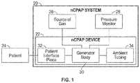
- FIG. 1is a block diagram illustrating one embodiment of a nasal continuous positive airway pressure system including an nCPAP device in accordance with principles of the present disclosure
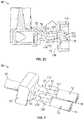
- FIG. 2 Ais a perspective view of a generator body in accordance with principles of the present disclosure and useful with the nCPAP device of FIG. 1 ;
- FIG. 2 Bis a perspective cross-sectional view of the generator body of FIG. 2 A ;
- FIG. 2 Cis a longitudinal cross-sectional view of the generator body of FIG. 2 A ;
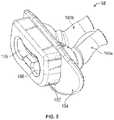
- FIG. 3is a perspective modeling of an internal fluid volume of the generator body of FIG. 2 A ;
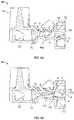
- FIG. 4 Ais a cross-sectional view of the generator body of FIG. 2 A and illustrating fluid flow during an inspiratory phase of operation;
- FIG. 4 Bis a cross-sectional view of the generator body of FIG. 2 A and illustrating fluid flow during an expiratory phase of operation;
- FIG. 5is a perspective view of a patient interface piece useful with the system of FIG. 1 ;
- FIG. 6 Ais a perspective view of another generator body in accordance with principles of the present disclosure and useful with the nCPAP device of FIG. 1 ;
- FIG. 6 Bis a perspective cross-sectional view of the generator body of FIG. 6 A ;
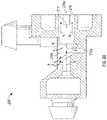
- FIG. 7is a longitudinal cross-sectional view of another generator body in accordance with principles of the present disclosure.
- FIG. 8 Ais a cross-sectional view of the generator body of FIG. 7 and illustrating formation of a jet stream during use;
- FIG. 8 Bis a cross-sectional view of the generator body of FIG. 7 and illustrating fluid flow during an inspiratory phase of operation;
- FIG. 8 Cis a cross-sectional view of the generator body of FIG. 7 and illustrating fluid flow during an expiratory phase of operation;
- FIG. 9is a perspective modeling of an internal fluid volume of the generator body of FIG. 7 ;
- FIG. 10is a graph of experimental test results comparing driving pressure requirements of generator bodies of the present disclosure with those of currently available nCPAP generator products.
- FIG. 11is a graph of experimental test results comparing the total imposed work-of-breathing requirements of the generator bodies of the present disclosure with those of currently available nCPAP generator products.
- nCPAPnasal continuous positive airway pressure
- the system 20is adapted to provide CPAP therapy to a patient 24 , and includes the nCPAP device 22 and a source of pressurized gas 26 .
- the nCPAP system 20can further optionally include a pressure monitor 28 .
- the nCPAP device 22is described in greater detail below, and generally includes a generator body 30 and a patient interface piece 32 .
- ambient air tubing 34can also be provided.
- the generator body 30is fluidly connected to the patient interface 32 and the optional ambient air tubing 34 , with the patient interface piece 32 being adapted to establish fluid communication with the patient's 24 nasal airways.
- the source of pressurized gas 26provides the generator body 30 with a continuous flow of gas (e.g., air and/or oxygen).
- the pressure monitor 28is also fluidly connected to the generator body 30 and samples or measures pressure therein.
- the generator body 30acts upon gas from the source 26 to generate and deliver a continuous positive airway pressure to the patient 24 via the patient interface piece 32 . As the patient 24 exhales, the exhaled air readily flows through the patient interface piece 32 /generator body 30 , and is exhausted from the nCPAP device 22 as described below.
- FIGS. 2 A and 2 BOne embodiment of the generator body 30 in accordance with principles of the present disclosure is shown in FIGS. 2 A and 2 B .
- the generator body 30is configured to establish CPAP for inspiratory and expiratory flow of gas to and from the patient 24 ( FIG. 1 ).
- the generator body 30forms or defines a supply gas inlet 40 , a chamber 42 (shown in FIG. 2 B ), and first and second flow circuits 44 a , 44 b (referenced generally in FIG. 2 A ; the first flow circuit 44 a being shown in greater detail in FIG. 2 B ).
- the inlet 40is configured for fluid connection to the source of pressurized gas 26 ( FIG. 1 ), and directs incoming gas into the chamber 42 .
- the flow circuits 44 a , 44 bare fluidly connected to the chamber 42 .
- gas flow provided at the inlet 40is directed through the chamber 42 and then toward the patient via the flow circuits 44 a , 44 b .
- the flow circuits 44 a , 44 bincorporate one or more features that promote exhausting of supplied gas and exhaled air during inspiratory and expiratory phases of operation with minimal patient work-of-breathing effort.
- the generator body 30can incorporate additional, optional components, such as a pressure monitoring port 48 , an exterior flange 50 , etc.
- the generator body 30can have a two (or more) piece construction, including a supply section 60 and a circuit section 62 .
- the sections 60 , 62can be separately formed (e.g., molded plastic) and assembled to another, with the supply section 60 forming the inlet 40 and the chamber 42 .
- the circuit section 62forms the flow circuits 44 a , 44 b .
- other constructionsare also envisioned, such as integrally constructing the generator body 30 as a single, homogenous body.
- the inlet 40can assume various forms (e.g., size and shape) appropriate for fluid connection to a supply tube (not shown) extending from the source of gas 26 ( FIG. 1 ).
- the chamber 42is fluidly connected to the supply inlet 40 and is fluidly open to the first and second flow circuits 44 a , 44 b , with FIG. 2 B illustrating fluid communication between the chamber 42 and the first flow circuit 44 a .
- an internal wall 64(referenced generally in FIG. 2 B ) provides or forms a manifold that is fluidly open to the chamber 42 and the flow circuits 44 a , 44 b.
- the first and second flow circuits 44 a , 44 bare, in some embodiments, identical such that the following description of the first flow circuit 44 a is equally applicable to the second flow circuit 44 b .
- the first flow circuit 44 aincludes or defines a nozzle 70 , a channel 72 , and at least one open port 74 .
- the nozzle 70is fluidly open to the channel 72 , as is the open port(s) 74 .
- gas flow from the nozzle 70is forced into the channel 72 in a direction of a naris or patient side 76 of the channel 72 .
- ambient aircan be entrained into the delivered gas flow and/or excess gas exhausted via the port 74 depending upon the patient's inspiratory requirements.
- exhaled air from the patient at the patient side 76can be exhausted through the open port(s) 74 , as can diverted jet stream flow from the nozzle 70 .
- the nozzle 70can assume various forms, and generally includes or defines an inlet end 80 and an outlet end 82 .
- the inlet end 80is fluidly connected to the chamber 42 .
- the outlet end 82is opposite the inlet end 80 , and is positioned to direct gas flow into the channel 72 .
- the outlet end 82has a reduced diameter as compared to the inlet end 80 .
- the channel 72is generally defined by a tube-like body 90 extending from the patient side 76 to a nozzle side 92 that is fluidly connected to the outlet end 82 of the nozzle 70 .
- the open port 74is formed through a thickness of a wall of the tubular body 90 , and thus is fluidly open to the channel 72 .
- a geometry of the channel 72 in extension from the open port 74 to the patient side 76establishes desired gas flow patterns during the inspiratory and expiratory phases of operation as described below.
- the channel 72can be described as having or being defined by an upper wall surface 100 and a lower wall surface 102 .
- the open port 74is fluidly open to the channel 72 at the upper wall surface 100 .
- the lower wall surface 102is defined opposite the upper wall surface 100 and includes first and second ramp regions 110 , 112 .
- the first ramp region 110extends from a port location 114 (otherwise aligned with the open port 74 ) to a transition location or peak 116 that is longitudinally displaced from the open port 74 in a direction of the patient side 76 .
- the channel 72can have an increased or elevated diameter at the port location 114 , for example by forming an angled guide surface 118 at the nozzle side 92 (e.g., the angled guide surface 118 can be arranged at an angle on the order of 40 degree from vertical in some embodiments).
- the first ramp region 110has an inclined or ascending orientation relative to the upper wall surface 100 in extension from the port location 114 to the transition location 116 . Stated otherwise, a linear distance between a plane (relative to the longitudinal cross-sectional view of FIG. 2 C ) of the upper wall surface 100 and the lower wall surface 102 at the port location 114 is greater than a linear distance between the upper wall surface 100 and the lower wall surface 102 at the transition location 116 .
- the second ramp region 112extends from the transition location 116 to or toward the patient side 76 .
- the second ramp region 112can be characterized as terminating at an intermediate location 120 that is spatially between the patient side 76 and the transition location 116 .
- the second ramp region 112has a declined or descending arrangement relative to the upper wall surface 100 in extension from the transition location 116 to the intermediate location 120 . Stated otherwise, a linear distance between the upper wall surface 100 and the lower wall surface 102 at the transition location 116 is less than a linear distance between the upper wall surface 100 and the lower wall surface 102 at the intermediate location 120 .
- the descending orientation or arrangement of the second ramp region 112can continue to the patient side 76 . With the one embodiment of FIG. 2 C , however, the channel 72 has a relatively uniform diameter in extension from the intermediate location 120 to the patient side 76 .
- a slope of the first ramp region 110can be less than a slope of the second ramp region 112 as shown. Alternatively, other slope relationships are also envisioned. Regardless, the ramp regions 110 , 112 serve as flow directors relative to gas flow to and from the patient side 76 as described below.
- the open port 74is open to the channel 72 at an interior aperture 120 in the upper wall surface 100 , and is open to ambient at an exterior aperture 122 .
- the port 74can have an expanding cross-sectional area in extension from the interior aperture 120 to the exterior aperture 122 .
- opposing side walls 124(theoretically represented in FIG. 3 ) of the port 74 can have an angular extension to the exterior aperture 122 , further contributing to the expanding cross-sectional area construction of the port 74 .
- the open port 74can be referred to as an ambient port, serving to fluidly connect the channel 72 with ambient air/pressure.
- an intermediate body or devicee.g., exhaust tubing, return line, etc.
- an intermediate body or devicee.g., exhaust tubing, return line, etc.
- the generator body 30is shown as including the single port 74 with each of the flow circuits 44 , in other embodiments, one or more secondary ports can be provided as described below.
- pressurized gase.g., from the source of gas 26 ( FIG. 1 )
- the supplied gasis forced into the flow circuits 44 .
- the nozzle 70converts the gas flow to a jet stream N that is directed into the channel 72 .
- FIG. 4 Aillustrates the generator body 30 during an inspiratory stage of operation.
- Pressurized gasis delivered to the chamber 42 via the supply inlet 40 and is directed toward the flow circuits 44 .
- the nozzle 70converts the delivered gas into a jet stream (represented by arrows N in FIG.
- the jet stream Nestablishes a continuous positive airway pressure within the channel 72 (i.e., the jet stream N momentum is converted into pressure) that is applied to the patient side 76 , and thus the patient. At least a portion of the jet stream N flow is directed through the channel 72 and delivered to/inhaled by the patient at the patient side 76 .
- ambient airrepresented by arrows A in FIG. 4 A
- a portion of the jet stream Nexperiences a recirculating flow R adjacent the open port 74 as well as along the second ramp region 112 .
- These recirculating flows Rdivert an excess portion (represented by arrow E in FIG. 4 A ) of the jet stream N and/or entrained air A to the open port 74 as exhaust flow.
- excess gasis exhausted via the port 74 .
- the jet stream Ncontinues to be generated by and emitted from the nozzle 70 into the channel 72 , maintaining the continuous positive airway pressure delivered to the patient due to the jet stream's momentum.
- Exhaled air(represented by arrows X in FIG. 4 B ) enters the channel 72 at the patient side 76 , and acts upon the jet stream N flow.
- the second ramp region 112defines a tapering hydraulic diameter that increases the magnitude of the velocity of the exhaled air X at the transition location or peak 116 .
- the second ramp region 112effectively “focuses” a portion of the exhaled air X “upwardly” toward the jet stream N flow. This focused, upward flow diverts or “turns” the jet stream N (and any entrained ambient air A) toward the open port 74 . Also, a recirculating flow (represented by arrow R in FIG. 4 B ) is formed between the jet stream N and the exhaled air X adjacent the upper wall surface 100 in a zone of the first ramp region 110 that enhances diversion of the jet stream N toward the open port 74 .
- the open port 74 the ramp regions 110 , 112 , and a geometry of the jet stream Ncombine to establish flow patterns that minimize resistance to the exhaled air X and patient effort required to draw the jet stream N back into the channel 72 upon inspiration. This results in low patient work-of-breathing during both inspiratory and expiratory operation.
- the ramp features described above in combination with one or more geometry characteristicsrender the generator body 30 capable of establishing desired CPAP levels at low driving pressures and with minimal patient work-of-breathing.
- the nozzle outlet end 82has a diameter (and thus a diameter of the resultant jet stream N) on the order of 0.04-0.07 inch, optionally 0.058 inch.
- a diameter (or height) of the channel 72 at the patient side 76is on the order of 0.10-0.16 inch, optionally 0.136 inch.
- the generator body 30optionally establishes a ratio of channel height (at the patient side 76 ) to jet diameter in the range of 2.29-2.50, optionally 2.34.
- An angle of incline (relative to horizontal) along the first ramp region 110is in the range of 5°-10°, optionally 7.1°; an angle of decline (relative to horizontal) along the second ramp region 112 is in the range of 12°-19°, optionally 16.5°.
- the optional pressure monitoring port 48is located to tap or sample air pressure within the generator body 30 .
- the pressure monitoring port 48can be fluidly connected to one or both of the flow circuits 44 a , 44 b , and provides a surface appropriate for connection to monitoring tubing (not shown) extending to the pressure monitor 28 ( FIG. 1 ). In other embodiments, the pressure monitoring port 48 can be omitted.
- the optional exterior flange 50surrounds the tube bodies 90 , and serves to direct or deflect exhausted airflow away from the patient.
- the exterior flange 50provides a surface for mounting of various other components, such as the patient interface 32 described below.
- the flange 50can be omitted.
- the generator body 30can incorporate additional features facilitating connection with other components of the nCPAP system 20 ( FIG. 1 ) and/or desired functioning.
- the tube bodies 90 associated with the flow circuits 44 a , 44 bcan form or define an exterior taper 140 adapted to promote a secured, sealed attachment with the patient interface piece 32 ( FIG. 1 ), along with radial slots 142 that provide a region from which pressure otherwise present in the corresponding channel 72 can be tapped or sampled.
- FIG. 5generally illustrates one exemplary embodiment of the patient interface piece 32 that includes a pair of nasal prongs 150 a , 150 b projecting from a base 152 .
- the base 152can incorporate additional features, such as a sealing flange 154 .
- the base 152is generally sized and shaped for assembly to the generator body 30 , for example via a perimeter shape including a shape of the flange 50 .
- the base 152forms a pair of apertures 156 sized to be received over respective ones of the fluid circuit tubular bodies 90 .
- the nasal prongs 150 a , 150 bmay be of any size and shape as are suitable for interacting with the patient's nares, and are fluidly open to the apertures 154 .
- Assembly of the patient interface piece 32 to the generator body 30generally entails establishing a fluid connection between the nasal prongs 150 a , 150 b , and the patient side 76 of a respective one of the flow circuits 44 a , 44 b .
- the patient interface 32can be a nasal mask.
- FIGS. 6 A and 6 BAnother generator body 200 in accordance with principles of the present disclosure and useful with the nCPAP system 20 ( FIG. 1 ) is shown in FIGS. 6 A and 6 B .
- the generator body 200forms or defines a gas supply inlet 202 , a chamber 204 , and first and second flow circuits 206 a , 206 b (one of which is more clearly visible in the view of FIG. 6 B ).
- the supply inlet 202 and the chamber 204are akin to the inlet 40 ( FIG. 2 A ) and the chamber 42 ( FIG. 2 B ) described above, with the chamber 204 fluidly connecting the supply inlet 202 with the flow circuits 206 a , 206 b .
- the flow circuits 206 a , 206 beach include a nozzle 210 , a channel 212 , and at least two open ports 214 .
- the nozzle 210is configured to convert gas flow from the chamber 204 into a jet stream directed to the channel 212 .
- the channel 212extends from the nozzle 210 , and terminates at a patient side 216 .
- the open ports 214are akin to the open port 74 ( FIG. 2 C ) described above, and are generally configured to facilitate exhaust of gas during an expiratory phase of operation and entrainment of ambient air (if necessary) during an inspiratory phase.
- the first flow circuit 206 aincludes a first or primary port 214 a and a second or secondary port 214 b .
- the primary port 214 ais open to the channel 212 at an interior aperture 220 and is open to ambient via an exterior aperture 222 in the generator body 200 .
- the secondary port 214 bis similarly open to the channel 212 at an interior aperture 224 and to ambient air via an exterior aperture 226 formed in a tubular body 228 of the channel 212 .
- the secondary port exterior aperture 222is fluidly open to a secondary chamber 230 defined between inner and outer housing sections 232 , 234 , with the secondary chamber 230 , in turn, being open to ambient via a passageway 236 through the generator body 200 .
- FIG. 7represents an alternative generator body 200 ′ that is highly akin to the generator body 200 of FIGS. 6 A and 6 B .
- the gas supply inlet 202is arranged parallel with the channel 212 (as compared to the more perpendicular arrangement of FIGS. 6 A and 6 B ).
- the secondary port 214 bis shown as being directly open to ambient at the exterior aperture 226 (i.e., the secondary chamber 230 and the passageway 236 of FIG. 6 B are omitted), with the secondary port exterior aperture 222 being formed in or at an exterior of the generator body 200 ′. From a functional standpoint, however, the generator bodies 200 , 200 ′ are identical.
- the primary port 214 ais formed through a thickness of the generator body 200 ′, and is generally defined by a leading end wall 240 and a trailing end wall 242 (relative to the longitudinal cross-sectional view of FIG. 7 ). As shown, the leading end wall 240 is proximate the nozzle 210 (as compared to the trailing end wall 242 ), and projects radially outwardly in extension from the channel 212 . Stated otherwise, the leading end wall 240 tapers inwardly from the exterior aperture 222 to the interior aperture 220 . Thus, relative to a centerline C of the channel 212 , extension of the leading end wall 240 defines an included angle ⁇ of less than 90°.
- the trailing end wall 242can extend between the apertures 220 , 222 in a more perpendicular fashion relative to the centerline C.
- the primary port 214 aoptionally has an expanding cross-sectional area in extension from the channel 212 to the exterior aperture 222 (i.e., a size of the primary port 214 a at the interior aperture 220 is less than a size at the exterior aperture 222 ).
- the secondary port 214 bextends from the channel 212 at a location generally opposite that of the primary port 214 a .
- the primary port 214 ais located at an upper wall surface 250 of the channel 212
- the secondary port 214 bis located at a lower wall surface 252 .
- the secondary port 214 bcan have the generally linear shape shown (in extension from the channel 212 ), and can be radially aligned with the primary port 214 a .
- the secondary port 214 bcan be located such that an axis of the secondary port 214 b extends through the primary port 214 a .
- the channel 212forms a region of increasing diameter between the nozzle 210 and the secondary port 214 b .
- an angled guide surface 254can be defined between a nozzle side 256 of the channel 212 and the secondary port interior aperture 224 .
- the secondary port 214 band in particular the secondary port interior aperture 224 , is “below” a centerline or axis of the nozzle 210 for reasons made clear below.
- the primary port 214 ais larger than the secondary port 214 b .
- a cross-sectional area of the primary port 214 a at the primary port interior aperture 220is greater than a cross-sectional area of the secondary port 214 b at the secondary port interior aperture 224 .
- a cross-sectional area of the primary port 214 a at the primary port exterior aperture 222is greater than a cross-sectional area of the secondary port exterior aperture 226 .
- the primary port 214 afacilitates a greater volumetric gas flow as compared to the secondary port 214 b.
- the open ports 214 a , 214 bare located in highly close proximity to the nozzle 210 .
- the flow direction of a jet stream (illustrated by arrow N in FIG. 8 A ) from the nozzle 210is generally unaligned with the ports 214 a , 214 b such that in the absence of other counteractive gas flows or pressures, the jet stream flow N from the nozzle 210 is primarily directed past the ports 214 a , 214 b and toward the patient side of the channel 212 .
- pressurized gase.g., from the source of gas 26 ( FIG. 1 )
- pressurized gasis provided to the chamber 204 via the supply inlet 202 .
- the supplied gasis forced into the flow circuits 206 .
- the nozzle 210 of each flow circuit 206converts the gas flow to the jet stream N that is directed into the corresponding channel 212 .
- an inspiratory phase of operationi.e., patient inhaling
- FIG. 8 Bat least a portion of the jet stream N passes through the channel 212 and is supplied to the patient via the patient side 216 .
- the jet stream N momentumdelivers a continuous positive pressure to the patient side 216 .
- ambient airis entrained into the delivered flow primarily via the primary port 214 a (represented by arrows A in FIG. 8 B ).
- the jet stream Nis generated so as to enhance entrainment of supplemental ambient air A for delivery to the patient side 216 , and thus the patient.
- excess gascan be exhausted from the channel 212 primarily via the secondary port 214 b (identified by arrows E in FIG. 8 B ).
- the jet stream N flow rateexceeds the inspiratory demand of the patient, excess gas is exhausted via the port(s) 214 a , 214 b.
- FIG. 8 CAn expiratory phase of operation (i.e., patient exhaling) is reflected in FIG. 8 C .
- the gas jet stream Nis delivered to the channel 212 at a fixed rate, maintaining the continuous positive airway pressure delivered to the patient by the jet stream's N momentum.
- Exhaled air(represented by arrows X in FIG. 8 C ) from the patient is delivered to the channel 212 via the patient side 216 and acts upon the jet stream N (as well as any entrained ambient air A). Because the jet stream N flow has a relatively low momentum, it is easily disrupted by the exhaled air X. Further, the secondary port 214 b presents a path of least resistance for the exhaled air X.
- the secondary port 214 bis located “below” the centerline of the jet stream N so that the exhaled air X is able to more easily flow “under” the jet stream N to the secondary port 214 b .
- the entrained ambient air A at the primary port 214 b(in combination with the jet stream N) slightly increases a resistance to flow of the exhaled air X to the primary port 214 a .
- the exhaled air Xflows primarily to the secondary port 214 b , with this flow direction causing the jet stream N flow to divert or “turn” toward the primary port 214 a .
- a significant portion of the jet stream Nreadily exhausts from the channel 212 .
- the open ports 214 a , 214 bcombine to establish flow patterns that minimize flow resistance to the exhaled air X and thus the corresponding patient's work-of-breathing.
- FIG. 9represents a modeling of an internal or fluid volume of the generator body 200 ′ and reflects the first and second flow circuits 206 a , 206 b as each having the nozzle 210 fluidly connected to the chamber 204 , as well as the primary and secondary ports 214 a , 214 b facilitating entrainment and exhaust of gas to/from the corresponding channel 212 .
- the generator body 200 ′can facilitate targeted patient CPAP levels at relatively low supply gas pressures. Further, the secondary exhaust port 214 b reduces fluctuation in the delivered CPAP pressure during both inhalation and exhalation such that the work-of-breathing required by a patient is kept very low.
- FIG. 10graphically illustrates test results of driving pressure as a function of supplied CPAP for the generator bodies 30 ( FIG. 2 A ), 200 ′ ( FIG. 7 ), as well as two currently available CPAP generator bodies.
- prototype CPAP generatorswere constructed in accordance with FIGS. 2 A and 7 , and were subjected to testing by supplying pressurized gas at varying levels to the generator body and recording the resulting level of produced CPAP.
- Test results for the generator body 30 of FIG. 2 Aare represented by the plot line 30 A in FIG. 10 ; the test results for the generator body 200 ′ of FIG. 7 are represented by the plot line 200 A in FIG. 10 .
- an Infant FlowTM CPAP generatoravailable from CareFusion, Inc.
- an AirLifeTM CPAP generatoravailable from CareFusion, Inc.
- the plot line IF in FIG. 10represents the test results for the Infant FlowTM generator;
- the plot line ALreflects the test results for the AirLifeTM generator.
- FIG. 10reveals that a target patient CPAP level can be achieved with the generator bodies of the present disclosure at a driving pressure that is less than those required by existing devices.
- a target patient CPAP level of 5 cm H 2 Omay be achieved with a driving pressure not greater than 18 cm H 2 O with the generator bodies 30 , 200 ′ of the present disclosure; in contrast, existing CPAP generators generally require a driving pressure of greater than 75 cm H 2 O to achieve a CPAP level of 5 cm H 2 O.
- a target patient CPAP level of 20 cm H 2 Ocan be achieved with the generator bodies 30 , 200 ′ of the present disclosure with a driving pressure of not greater than 60 cm H 2 O; by way of comparison, existing CPAP generators generally require a driving pressure of greater than 275 cm H 2 O to achieve a CPAP level of 20 cm H 2 O.
- the reduced driving pressure requirementscan provide enhanced safety in that the source of pressurized gas 26 ( FIG. 1 ), that is otherwise in relatively close proximity to the patient during use, operates at a lower pressure as compared to conventional nCPAP systems.
- the generator bodies of the present disclosureare capable of operating within the driving pressure limits of common ventilators, thereby obviating the need for the caregiver to maintain a separate source of pressurized gas (apart from a ventilator that is otherwise normally on-hand) to perform CPAP procedures.
- the generator bodies of the present disclosurehave surprisingly been found to reduce the total imposed work-of-breathing (WOB) of the patient.
- the flow directing featuree.g., the ramp regions 110 , 112 of FIG. 2 C
- the optimized primary and secondary ambient portse.g., the ports 214 a , 214 b of FIG. 7
- the generator bodies 200FIG. 6 A
- 200 ′FIG. 7
- the CPAP-generating jet streamto optimally self-adjust thereby keeping pressure fluctuations beneficially low (as compared to currently available CPAP generators) in turn lowering the total imposed WOB.
- Total imposed WOB testingwas performed on the prototype generator bodies 30 , 200 ′, the Infant FlowTM generator, and the AirLifeTM generator samples used with the driving pressure tests described above by connecting the samples to an industry-accepted lung simulator (IngMar Medical ASL 5000 Breathing Simulator utilizing Software Version 2.2.22a and available from IngMar Medical, Ltd., of Pittsburgh, Pa.).
- Total imposed WOBwas measured and recorded at several simulated patient tidal volumes for each generator at a CPAP setting of 5 cm H 2 O.
- the total imposed WOB test resultsare shown in FIG. 11 .
- the results for the generator body 30are plotted by the line 30 B in FIG. 11 ; the test results for the generator body 200 ′ are plotted by the line 200 B.
- the total imposed WOB test results for the available Infant FlowTM CPAP generatorare plotted by the line IF, whereas the test results for the available AirLifeTM CPAP generator are plotted by the line AL.
- the total imposed WOB for a 9 mL patient tidal volumeis not greater than 80 mJ/L using the generator bodies of the present disclosure.
- the total imposed WOB for a 9 mL patient tidal volumeis greater than 115 mJ/L with currently available CPAP generators (that otherwise require the comparatively higher driving pressures as described above).
- the total imposed WOB for a 24 mL patient tidal volumeis not greater than 130 mJ/L with the generator bodies of the present disclosure; in contrast, the total imposed WOB requirements at a 24 mL patient tidal volume is greater than 140 mJ/L with currently available CPAP generators (that require comparatively higher driving pressures).
- a total imposed WOB parameter of a generator bodyis determined by testing with the above-identified. IngMar Medical ASL 5000 Breathing Simulator.
- the CPAP devices, and related systems and methods, of the present disclosureprovide a marked improvement over previous designs.
- the generator bodies envisioned by the present disclosurehave reduced driving pressure requirements necessary for delivering desired levels of CPAP, as well as reduced total imposed WOB properties.
- the generator bodies of the present disclosurecan be relatively small as compared to existing designs.
Landscapes
- Health & Medical Sciences (AREA)
- Pulmonology (AREA)
- Emergency Medicine (AREA)
- Life Sciences & Earth Sciences (AREA)
- General Health & Medical Sciences (AREA)
- Biomedical Technology (AREA)
- Heart & Thoracic Surgery (AREA)
- Hematology (AREA)
- Engineering & Computer Science (AREA)
- Animal Behavior & Ethology (AREA)
- Anesthesiology (AREA)
- Public Health (AREA)
- Veterinary Medicine (AREA)
- Otolaryngology (AREA)
- Measurement Of The Respiration, Hearing Ability, Form, And Blood Characteristics Of Living Organisms (AREA)
- Respiratory Apparatuses And Protective Means (AREA)
- Infusion, Injection, And Reservoir Apparatuses (AREA)
- Percussion Or Vibration Massage (AREA)
- Surgical Instruments (AREA)
Abstract
Description
Claims (16)
Priority Applications (2)
| Application Number | Priority Date | Filing Date | Title |
|---|---|---|---|
| US16/390,068US11547826B2 (en) | 2010-10-05 | 2019-04-22 | Non-invasive breathing assistance apparatus and method |
| US17/972,221US20230058528A1 (en) | 2010-10-05 | 2022-10-24 | Non-invasive breathing assistance apparatus and method |
Applications Claiming Priority (3)
| Application Number | Priority Date | Filing Date | Title |
|---|---|---|---|
| US12/898,265US8607794B2 (en) | 2010-10-05 | 2010-10-05 | Non-invasive breathing assistance apparatus and method |
| US14/085,708US10307553B2 (en) | 2010-10-05 | 2013-11-20 | Non-invasive breathing assistance apparatus and method |
| US16/390,068US11547826B2 (en) | 2010-10-05 | 2019-04-22 | Non-invasive breathing assistance apparatus and method |
Related Parent Applications (1)
| Application Number | Title | Priority Date | Filing Date |
|---|---|---|---|
| US14/085,708ContinuationUS10307553B2 (en) | 2010-10-05 | 2013-11-20 | Non-invasive breathing assistance apparatus and method |
Related Child Applications (1)
| Application Number | Title | Priority Date | Filing Date |
|---|---|---|---|
| US17/972,221ContinuationUS20230058528A1 (en) | 2010-10-05 | 2022-10-24 | Non-invasive breathing assistance apparatus and method |
Publications (2)
| Publication Number | Publication Date |
|---|---|
| US20190247603A1 US20190247603A1 (en) | 2019-08-15 |
| US11547826B2true US11547826B2 (en) | 2023-01-10 |
Family
ID=45888724
Family Applications (4)
| Application Number | Title | Priority Date | Filing Date |
|---|---|---|---|
| US12/898,265Active2031-05-22US8607794B2 (en) | 2010-10-05 | 2010-10-05 | Non-invasive breathing assistance apparatus and method |
| US14/085,708Active2031-11-15US10307553B2 (en) | 2010-10-05 | 2013-11-20 | Non-invasive breathing assistance apparatus and method |
| US16/390,068Active2033-02-17US11547826B2 (en) | 2010-10-05 | 2019-04-22 | Non-invasive breathing assistance apparatus and method |
| US17/972,221PendingUS20230058528A1 (en) | 2010-10-05 | 2022-10-24 | Non-invasive breathing assistance apparatus and method |
Family Applications Before (2)
| Application Number | Title | Priority Date | Filing Date |
|---|---|---|---|
| US12/898,265Active2031-05-22US8607794B2 (en) | 2010-10-05 | 2010-10-05 | Non-invasive breathing assistance apparatus and method |
| US14/085,708Active2031-11-15US10307553B2 (en) | 2010-10-05 | 2013-11-20 | Non-invasive breathing assistance apparatus and method |
Family Applications After (1)
| Application Number | Title | Priority Date | Filing Date |
|---|---|---|---|
| US17/972,221PendingUS20230058528A1 (en) | 2010-10-05 | 2022-10-24 | Non-invasive breathing assistance apparatus and method |
Country Status (9)
| Country | Link |
|---|---|
| US (4) | US8607794B2 (en) |
| EP (1) | EP2624901B1 (en) |
| CN (2) | CN105688317B (en) |
| AU (1) | AU2011312232B2 (en) |
| BR (1) | BR112013007769A2 (en) |
| CA (1) | CA2812235C (en) |
| ES (1) | ES2627123T3 (en) |
| MX (2) | MX384455B (en) |
| WO (1) | WO2012047903A2 (en) |
Families Citing this family (27)
| Publication number | Priority date | Publication date | Assignee | Title |
|---|---|---|---|---|
| CA3117178C (en) | 2009-12-23 | 2023-06-13 | Fisher & Paykel Healthcare Limited | An interface and a method of supplying breathing gas |
| US10159812B2 (en)* | 2011-03-29 | 2018-12-25 | Carefusion 207, Inc. | Flow splitting nCPAP device |
| US20130284176A1 (en)* | 2012-04-03 | 2013-10-31 | Benjamin D. Dickerson | Force gauged continuous positive airway pressure nasal interface |
| US9259548B2 (en)* | 2012-04-30 | 2016-02-16 | Carefusion 207, Inc. | Patient nasal interface for use with a nasal airway pressure system |
| US9375542B2 (en) | 2012-11-08 | 2016-06-28 | Covidien Lp | Systems and methods for monitoring, managing, and/or preventing fatigue during ventilation |
| WO2014091362A1 (en)* | 2012-12-11 | 2014-06-19 | Koninklijke Philips N.V. | Nasal cannula system and method |
| US10307552B2 (en)* | 2013-09-06 | 2019-06-04 | Breathe Technologies, Inc. | Jet pump adaptor for ventilation system |
| CN110711304B (en)* | 2014-06-18 | 2024-03-15 | 费雪派克医疗保健有限公司 | Patient interface and components |
| WO2016159784A1 (en)* | 2015-03-30 | 2016-10-06 | Fisher & Paykel Healthcare Limited | Adaptor for respiratory assistance systems |
| EP4186548A1 (en) | 2015-04-02 | 2023-05-31 | Hill-Rom Services PTE. LTD. | Mask leakage detection for a respiratory device |
| CN108144168A (en)* | 2015-05-16 | 2018-06-12 | 苏州汉方医药有限公司 | A kind for the treatment of medicine box of manual microactuator suspension particle generator and chemicals medicine composition |
| USD833599S1 (en)* | 2015-09-09 | 2018-11-13 | Neores Ab | Mask for respiratory therapies |
| FR3046552B1 (en)* | 2016-01-07 | 2018-02-16 | Aptar France Sas | NASAL POWDER DISTRIBUTION DEVICE. |
| RU167390U1 (en)* | 2016-06-21 | 2017-01-10 | Публичное акционерное общество "Техприбор" | DEVICE FOR NON-INVASIVE ARTIFICIAL VENTILATION OF LUNG NEWBORNS |
| AU2017343672A1 (en)* | 2016-10-10 | 2019-05-30 | Oventus Medical Limited | A breathing assist system including an oral appliance and connector system therefor |
| GB2555625B (en) | 2016-11-04 | 2020-10-14 | Viomedex Ltd | Therapy delivery device |
| GB2570053B (en)* | 2016-11-04 | 2020-04-29 | Viomedex Ltd | Therapy delivery device |
| US11202879B2 (en)* | 2017-12-29 | 2021-12-21 | Koninklijke Philips N.V. | Humidifier and airway pressure support system including same |
| GB201818584D0 (en)* | 2018-11-14 | 2018-12-26 | Exhalation Tech Limited | A device to measure breath humidity |
| WO2020150905A1 (en)* | 2019-01-22 | 2020-07-30 | 深圳迈瑞生物医疗电子股份有限公司 | Ventilation fitting and patient ventilation interface |
| CA3163431A1 (en)* | 2020-01-13 | 2021-07-22 | David M. Kane | New nasal respiratory apparatus |
| CA3172937A1 (en)* | 2020-04-16 | 2021-10-21 | Neores Ab | Device and system for respiratory support |
| CN115427096A (en)* | 2020-04-16 | 2022-12-02 | 尼奥雷斯公司 | Device and system for respiratory support |
| CN113491351A (en)* | 2021-06-07 | 2021-10-12 | 中国科学院深圳先进技术研究院 | Electronic cigarette utensil |
| CN113893418B (en)* | 2021-12-02 | 2022-07-12 | 时新(上海)产品设计有限公司 | Spray device |
| EP4587087A1 (en)* | 2022-09-14 | 2025-07-23 | Fisher & Paykel Healthcare Limited | A breathing assistance apparatus for providing resipratory therapy |
| USD1071205S1 (en)* | 2024-08-01 | 2025-04-15 | Miao Li | Water reservoir lid adapter for CPAP cleaner |
Citations (59)
| Publication number | Priority date | Publication date | Assignee | Title |
|---|---|---|---|---|
| US4098290A (en) | 1976-12-02 | 1978-07-04 | Glenn Joseph G | Miniature intermittent positive pressure breathing valve |
| US4248218A (en) | 1978-09-22 | 1981-02-03 | Fischer Charles M | Gas administration scavenging mask |
| US4262665A (en) | 1979-06-27 | 1981-04-21 | Roalstad W L | Intramedullary compression device |
| US4274406A (en) | 1979-09-04 | 1981-06-23 | Bartholomew Victor L | Tracheotomy mask |
| US4681100A (en) | 1984-12-28 | 1987-07-21 | Konstruktiva Trencin, Narodny Podnik | Multinozzle generator for high frequency nozzle ventilation of lungs |
| US4782832A (en) | 1987-07-30 | 1988-11-08 | Puritan-Bennett Corporation | Nasal puff with adjustable sealing means |
| US4821736A (en) | 1988-03-22 | 1989-04-18 | Dale Medical Products, Inc. | Head-mounted device for supporting breathing circuit tubes and sensor |
| US4915105A (en) | 1988-10-28 | 1990-04-10 | Lee Tien Chu | Miniature respiratory apparatus |
| WO1990006149A1 (en) | 1988-12-06 | 1990-06-14 | Conny Peder Gunnar Moa | A device for generating by means of ejector action a continuous positive airway pressure (cpap) during spontaneous breathing |
| US5046491A (en) | 1990-03-27 | 1991-09-10 | Derrick Steven J | Apparatus and method for respired gas collection and analysis |
| US5113857A (en) | 1990-08-27 | 1992-05-19 | Stair Dickerman | Breathing gas delivery system and holding clip member therefor |
| US5231979A (en) | 1992-02-14 | 1993-08-03 | Puritan-Bennett Corporation | Humidifier for CPAP device |
| US5451190A (en) | 1992-04-10 | 1995-09-19 | Varioraw Percutive S.A. | Apparatus for respiratory therapy |
| US5477852A (en) | 1991-10-29 | 1995-12-26 | Airways Ltd., Inc. | Nasal positive airway pressure apparatus and method |
| US5687715A (en) | 1991-10-29 | 1997-11-18 | Airways Ltd Inc | Nasal positive airway pressure apparatus and method |
| US5806516A (en) | 1997-03-27 | 1998-09-15 | Beattie; Kathy | Endotracheal tube stabilizer |
| US5975077A (en) | 1998-07-28 | 1999-11-02 | Hamilton Medical, Inc. | Method and apparatus for assisting in breathing |
| US6119694A (en) | 1997-07-24 | 2000-09-19 | Respironics Georgia, Inc. | Nasal mask and headgear |
| US6253766B1 (en)* | 1999-08-24 | 2001-07-03 | Dhd Healthcare Corporation | Continuous positive airway pressure therapy device |
| US20020053347A1 (en) | 1999-06-18 | 2002-05-09 | Saeed Ziaee | Nasal Mask |
| US20030000527A1 (en) | 2000-05-12 | 2003-01-02 | Alex Stenzler | Method and apparatus for injecting sighs during the administration of continuous positive airway pressure therapy |
| US20030010339A1 (en) | 1999-02-03 | 2003-01-16 | University Of Florida | Method and apparatus for nullifying the imposed work of breathing |
| US20030047185A1 (en) | 2001-09-13 | 2003-03-13 | Olsen Gregory James | Breathing assistance apparatus |
| US20030079749A1 (en) | 2001-10-25 | 2003-05-01 | Roger Strickland | Nasal cannula |
| US6595215B2 (en) | 2000-03-13 | 2003-07-22 | Innomed Technologies, Inc. | Ventilation interface for sleep apnea therapy |
| US20030200970A1 (en) | 2002-04-29 | 2003-10-30 | Alex Stenzler | Infant breathing assist apparatus |
| US20040040560A1 (en) | 2002-08-30 | 2004-03-04 | Euliano Neil R | Method and apparatus for predicting work of breathing |
| US20040065330A1 (en) | 2002-07-15 | 2004-04-08 | Landis Robert M. | Dynamic infant nasal CPAP system and method |
| US6769432B1 (en) | 2002-04-10 | 2004-08-03 | Hamilton Medical, Inc. | Method and apparatus for non-abrasive cushioning seal of assisted breathing devices |
| WO2004105846A2 (en) | 2003-05-21 | 2004-12-09 | Seleon Gmbh | Control device for anti-snoring apparatus and an anti-snoring apparatus, for example for copd treatment |
| US20050011524A1 (en) | 2003-07-17 | 2005-01-20 | Marguerite Thomlinson | Nasal interface apparatus |
| US20050133039A1 (en) | 2003-08-05 | 2005-06-23 | Wood Thomas J. | Nasal ventilation interface and system |
| US20050199242A1 (en) | 2004-03-11 | 2005-09-15 | Ric Investments, Llc | Patient interface device |
| US20050241644A1 (en) | 2004-04-09 | 2005-11-03 | Resmed Limited | Nasal assembly |
| US6997187B2 (en) | 2003-09-10 | 2006-02-14 | Innomed Technologies, Inc. | Nasal interface and system including ventilation insert |
| US7000613B2 (en) | 2003-08-06 | 2006-02-21 | Innomed Technologies, Inc. | Nasal interface and system including ventilation insert |
| US20060042634A1 (en) | 2004-08-31 | 2006-03-02 | Nalagatla Anil K | Device for connecting a cannula to a medical effector system |
| US20060130840A1 (en) | 2004-11-22 | 2006-06-22 | Oridion Medical (1987) Ltd. | Oral nasal cannula |
| US20060174887A1 (en) | 2004-12-10 | 2006-08-10 | Sanjay Chandran | Ventilation interface |
| US20060180149A1 (en) | 2003-07-22 | 2006-08-17 | Hasdi Matarasso | A respiratory aid system and method |
| US20060266361A1 (en) | 2005-05-31 | 2006-11-30 | Shara Hernandez | Ventilation interface |
| US7152604B2 (en) | 2000-06-13 | 2006-12-26 | Scott Laboratories, Inc. | Apparatus and method for mask free delivery of an inspired gas mixture and gas sampling |
| EP1759731A1 (en) | 2005-09-01 | 2007-03-07 | Deas S.R.L. | Ventilatory support device |
| US20070074724A1 (en) | 2005-09-30 | 2007-04-05 | Steven Duquette | Venturi geometry design for flow-generator patient circuit |
| US7219669B1 (en) | 1999-06-08 | 2007-05-22 | Sleepnet Corporation | Nose mask |
| US20070125379A1 (en)* | 2005-12-02 | 2007-06-07 | Brian Pierro | Nasal continuous positive airway pressure device and system |
| US20070125384A1 (en) | 2005-12-02 | 2007-06-07 | Chris Zollinger | Infant nasal interface mask |
| US20070125387A1 (en) | 2005-12-02 | 2007-06-07 | Chris Zollinger | Infant nasal interface prong device |
| US20070163600A1 (en) | 2006-01-11 | 2007-07-19 | Leslie Hoffman | User interface and head gear for a continuous positive airway pressure device |
| US20070175473A1 (en) | 2005-09-12 | 2007-08-02 | Lewis Charles A | High flow therapy device utilizing a non-sealing respiratory interface and related methods |
| US20070186930A1 (en) | 2003-12-31 | 2007-08-16 | Resmed Limited | Compact oronasal patient interface |
| US20070246043A1 (en) | 2004-04-15 | 2007-10-25 | Resmed Limited | Positive-Air-Pressure Machine Conduit |
| US7353826B2 (en) | 2003-08-08 | 2008-04-08 | Cardinal Health 205, Inc. | Sealing nasal cannula |
| US20080295846A1 (en) | 2007-05-29 | 2008-12-04 | Steve Han | Integrated mask and prongs for nasal CPAP |
| US20090126731A1 (en) | 2007-11-19 | 2009-05-21 | Allegiance Corporation | Patient interface assembly for respiratory therapy |
| WO2009078805A1 (en) | 2007-12-19 | 2009-06-25 | Ventinvent Ab | A nebulising device for use in a cpap-system |
| US20090165799A1 (en)* | 2007-12-28 | 2009-07-02 | Viasys Manufacturing, Inc. | Continuous positive airway pressure device |
| US20100252044A1 (en) | 2007-12-28 | 2010-10-07 | Care Fusion | Continuous positive airway pressure device and method |
| US20100252039A1 (en)* | 2009-04-02 | 2010-10-07 | Breathe Technologies, Inc. | Methods, systems and devices for non-invasive open ventilation with gas delivery nozzles in free space |
- 2010
- 2010-10-05USUS12/898,265patent/US8607794B2/enactiveActive
- 2011
- 2011-10-04BRBR112013007769Apatent/BR112013007769A2/ennot_activeApplication Discontinuation
- 2011-10-04CNCN201610127270.8Apatent/CN105688317B/enactiveActive
- 2011-10-04ESES11831465.7Tpatent/ES2627123T3/enactiveActive
- 2011-10-04EPEP11831465.7Apatent/EP2624901B1/enactiveActive
- 2011-10-04WOPCT/US2011/054787patent/WO2012047903A2/enactiveApplication Filing
- 2011-10-04CACA2812235Apatent/CA2812235C/enactiveActive
- 2011-10-04CNCN201180047696.8Apatent/CN103140253B/enactiveActive
- 2011-10-04MXMX2019001329Apatent/MX384455B/enunknown
- 2011-10-04MXMX2013003720Apatent/MX341635B/enactiveIP Right Grant
- 2011-10-04AUAU2011312232Apatent/AU2011312232B2/enactiveActive
- 2013
- 2013-11-20USUS14/085,708patent/US10307553B2/enactiveActive
- 2019
- 2019-04-22USUS16/390,068patent/US11547826B2/enactiveActive
- 2022
- 2022-10-24USUS17/972,221patent/US20230058528A1/enactivePending
Patent Citations (77)
| Publication number | Priority date | Publication date | Assignee | Title |
|---|---|---|---|---|
| US4098290A (en) | 1976-12-02 | 1978-07-04 | Glenn Joseph G | Miniature intermittent positive pressure breathing valve |
| US4248218A (en) | 1978-09-22 | 1981-02-03 | Fischer Charles M | Gas administration scavenging mask |
| US4262665A (en) | 1979-06-27 | 1981-04-21 | Roalstad W L | Intramedullary compression device |
| US4274406A (en) | 1979-09-04 | 1981-06-23 | Bartholomew Victor L | Tracheotomy mask |
| US4681100A (en) | 1984-12-28 | 1987-07-21 | Konstruktiva Trencin, Narodny Podnik | Multinozzle generator for high frequency nozzle ventilation of lungs |
| US4782832A (en) | 1987-07-30 | 1988-11-08 | Puritan-Bennett Corporation | Nasal puff with adjustable sealing means |
| US4821736A (en) | 1988-03-22 | 1989-04-18 | Dale Medical Products, Inc. | Head-mounted device for supporting breathing circuit tubes and sensor |
| US4915105A (en) | 1988-10-28 | 1990-04-10 | Lee Tien Chu | Miniature respiratory apparatus |
| WO1990006149A1 (en) | 1988-12-06 | 1990-06-14 | Conny Peder Gunnar Moa | A device for generating by means of ejector action a continuous positive airway pressure (cpap) during spontaneous breathing |
| US5193532A (en) | 1988-12-06 | 1993-03-16 | Moa Conny P G | Device for generating by means of ejector action a continuous positive airway pressure (cpap) during spontaneous breathing |
| US5046491A (en) | 1990-03-27 | 1991-09-10 | Derrick Steven J | Apparatus and method for respired gas collection and analysis |
| US5113857A (en) | 1990-08-27 | 1992-05-19 | Stair Dickerman | Breathing gas delivery system and holding clip member therefor |
| US5477852A (en) | 1991-10-29 | 1995-12-26 | Airways Ltd., Inc. | Nasal positive airway pressure apparatus and method |
| US5687715A (en) | 1991-10-29 | 1997-11-18 | Airways Ltd Inc | Nasal positive airway pressure apparatus and method |
| US5231979A (en) | 1992-02-14 | 1993-08-03 | Puritan-Bennett Corporation | Humidifier for CPAP device |
| US5451190A (en) | 1992-04-10 | 1995-09-19 | Varioraw Percutive S.A. | Apparatus for respiratory therapy |
| US5806516A (en) | 1997-03-27 | 1998-09-15 | Beattie; Kathy | Endotracheal tube stabilizer |
| US6119694A (en) | 1997-07-24 | 2000-09-19 | Respironics Georgia, Inc. | Nasal mask and headgear |
| US5975077A (en) | 1998-07-28 | 1999-11-02 | Hamilton Medical, Inc. | Method and apparatus for assisting in breathing |
| US6820618B2 (en) | 1999-02-03 | 2004-11-23 | University Of Florida Research Foundation, Incorporated | Method and apparatus for nullifying the imposed work of breathing |
| US20030010339A1 (en) | 1999-02-03 | 2003-01-16 | University Of Florida | Method and apparatus for nullifying the imposed work of breathing |
| US7219669B1 (en) | 1999-06-08 | 2007-05-22 | Sleepnet Corporation | Nose mask |
| US20020053347A1 (en) | 1999-06-18 | 2002-05-09 | Saeed Ziaee | Nasal Mask |
| US6253766B1 (en)* | 1999-08-24 | 2001-07-03 | Dhd Healthcare Corporation | Continuous positive airway pressure therapy device |
| US6595215B2 (en) | 2000-03-13 | 2003-07-22 | Innomed Technologies, Inc. | Ventilation interface for sleep apnea therapy |
| US6863069B2 (en) | 2000-03-13 | 2005-03-08 | Innomed Technologies, Inc. | Nasal ventilation interface |
| US20030000527A1 (en) | 2000-05-12 | 2003-01-02 | Alex Stenzler | Method and apparatus for injecting sighs during the administration of continuous positive airway pressure therapy |
| US7152604B2 (en) | 2000-06-13 | 2006-12-26 | Scott Laboratories, Inc. | Apparatus and method for mask free delivery of an inspired gas mixture and gas sampling |
| US20030047185A1 (en) | 2001-09-13 | 2003-03-13 | Olsen Gregory James | Breathing assistance apparatus |
| US20040244804A1 (en) | 2001-09-13 | 2004-12-09 | Olsen Gregory James | Breathing assistance apparatus |
| US20030079749A1 (en) | 2001-10-25 | 2003-05-01 | Roger Strickland | Nasal cannula |
| US6769432B1 (en) | 2002-04-10 | 2004-08-03 | Hamilton Medical, Inc. | Method and apparatus for non-abrasive cushioning seal of assisted breathing devices |
| US20030200970A1 (en) | 2002-04-29 | 2003-10-30 | Alex Stenzler | Infant breathing assist apparatus |
| US20040065330A1 (en) | 2002-07-15 | 2004-04-08 | Landis Robert M. | Dynamic infant nasal CPAP system and method |
| US7156096B2 (en) | 2002-07-15 | 2007-01-02 | Landis Robert M | Dynamic infant nasal CPAP system and method |
| US20040040560A1 (en) | 2002-08-30 | 2004-03-04 | Euliano Neil R | Method and apparatus for predicting work of breathing |
| WO2004105846A2 (en) | 2003-05-21 | 2004-12-09 | Seleon Gmbh | Control device for anti-snoring apparatus and an anti-snoring apparatus, for example for copd treatment |
| US20050011524A1 (en) | 2003-07-17 | 2005-01-20 | Marguerite Thomlinson | Nasal interface apparatus |
| US20060180149A1 (en) | 2003-07-22 | 2006-08-17 | Hasdi Matarasso | A respiratory aid system and method |
| US7191781B2 (en) | 2003-08-05 | 2007-03-20 | Innomed Technologies, Inc. | Nasal ventilation interface and system |
| US20050133039A1 (en) | 2003-08-05 | 2005-06-23 | Wood Thomas J. | Nasal ventilation interface and system |
| US7000613B2 (en) | 2003-08-06 | 2006-02-21 | Innomed Technologies, Inc. | Nasal interface and system including ventilation insert |
| US7353826B2 (en) | 2003-08-08 | 2008-04-08 | Cardinal Health 205, Inc. | Sealing nasal cannula |
| US6997187B2 (en) | 2003-09-10 | 2006-02-14 | Innomed Technologies, Inc. | Nasal interface and system including ventilation insert |
| US20070186930A1 (en) | 2003-12-31 | 2007-08-16 | Resmed Limited | Compact oronasal patient interface |
| US20060231103A1 (en) | 2004-03-11 | 2006-10-19 | Matula Jerome Jr | Patient interface device |
| US20050199242A1 (en) | 2004-03-11 | 2005-09-15 | Ric Investments, Llc | Patient interface device |
| US20050241644A1 (en) | 2004-04-09 | 2005-11-03 | Resmed Limited | Nasal assembly |
| US20070246043A1 (en) | 2004-04-15 | 2007-10-25 | Resmed Limited | Positive-Air-Pressure Machine Conduit |
| US20060042634A1 (en) | 2004-08-31 | 2006-03-02 | Nalagatla Anil K | Device for connecting a cannula to a medical effector system |
| US20060042631A1 (en) | 2004-08-31 | 2006-03-02 | Martin James F | Apparatus to deliver oxygen to a patient |
| US20060130840A1 (en) | 2004-11-22 | 2006-06-22 | Oridion Medical (1987) Ltd. | Oral nasal cannula |
| US20060174887A1 (en) | 2004-12-10 | 2006-08-10 | Sanjay Chandran | Ventilation interface |
| US20060266361A1 (en) | 2005-05-31 | 2006-11-30 | Shara Hernandez | Ventilation interface |
| US20070056587A1 (en) | 2005-09-01 | 2007-03-15 | Deas S.R.L. | Medical device for a patient's ventilatory support |
| EP1759731A1 (en) | 2005-09-01 | 2007-03-07 | Deas S.R.L. | Ventilatory support device |
| US20070175473A1 (en) | 2005-09-12 | 2007-08-02 | Lewis Charles A | High flow therapy device utilizing a non-sealing respiratory interface and related methods |
| US20070074724A1 (en) | 2005-09-30 | 2007-04-05 | Steven Duquette | Venturi geometry design for flow-generator patient circuit |
| CN101365508A (en) | 2005-09-30 | 2009-02-11 | 伟亚医疗系统制造有限公司 | Venturi geometry design for flow-generator patient circuit |
| US8100125B2 (en) | 2005-09-30 | 2012-01-24 | Carefusion 207, Inc. | Venturi geometry design for flow-generator patient circuit |
| CN101541288A (en) | 2005-12-02 | 2009-09-23 | 阿利吉安斯公司 | Baby Nasal Interface Mask |
| US20070125387A1 (en) | 2005-12-02 | 2007-06-07 | Chris Zollinger | Infant nasal interface prong device |
| US20070125384A1 (en) | 2005-12-02 | 2007-06-07 | Chris Zollinger | Infant nasal interface mask |
| US20070125379A1 (en)* | 2005-12-02 | 2007-06-07 | Brian Pierro | Nasal continuous positive airway pressure device and system |
| CN101370548A (en) | 2005-12-02 | 2009-02-18 | 阿利吉安斯公司 | Infant Nasal Interface Prong Device |
| US20100108073A1 (en) | 2005-12-02 | 2010-05-06 | Carefusion 2200, Inc. | Nasal interface prong device |
| CN101588833A (en) | 2005-12-02 | 2009-11-25 | 阿利吉安斯公司 | Nasal continuous positive airway pressure device and system |
| US7578294B2 (en) | 2005-12-02 | 2009-08-25 | Allegiance Corporation | Nasal continuous positive airway pressure device and system |
| US20070163600A1 (en) | 2006-01-11 | 2007-07-19 | Leslie Hoffman | User interface and head gear for a continuous positive airway pressure device |
| US20080295846A1 (en) | 2007-05-29 | 2008-12-04 | Steve Han | Integrated mask and prongs for nasal CPAP |
| CN101678188A (en) | 2007-05-29 | 2010-03-24 | 卡迪纳尔健康207公司 | Integrated mask and prongs for nasal cpap |
| US8833372B2 (en) | 2007-05-29 | 2014-09-16 | Carefusion 207, Inc. | Integrated mask and prongs for nasal CPAP |
| US20090126731A1 (en) | 2007-11-19 | 2009-05-21 | Allegiance Corporation | Patient interface assembly for respiratory therapy |
| WO2009078805A1 (en) | 2007-12-19 | 2009-06-25 | Ventinvent Ab | A nebulising device for use in a cpap-system |
| US20090165799A1 (en)* | 2007-12-28 | 2009-07-02 | Viasys Manufacturing, Inc. | Continuous positive airway pressure device |
| US20100252044A1 (en) | 2007-12-28 | 2010-10-07 | Care Fusion | Continuous positive airway pressure device and method |
| US20100252039A1 (en)* | 2009-04-02 | 2010-10-07 | Breathe Technologies, Inc. | Methods, systems and devices for non-invasive open ventilation with gas delivery nozzles in free space |
Non-Patent Citations (12)
| Title |
|---|
| Australian Examination Report No. 1 for Application No. 2011312232, dated Aug. 3, 2015, 3 pages. |
| Canadian Office Action for Application No. 2812235, dated Jun. 20, 2017, 5 pages. |
| Chinese Office Action for Application No. 201610127270.8, dated Jul. 26, 2017, 3 pages excluding translation. |
| Chinese Office Action in Chinese Patent Application No. CN201180047696.8 dated Jan. 5, 2015, 15 pages including English summary. |
| European Office Action for Application No. 11831465.7, dated Nov. 10, 2015, 6 pages. |
| European Search Report in European Patent Application No. 11831465.7 dated Dec. 5, 2014, 13 pages. |
| International Preliminary Report on Patentability in International Patent Application No. PCT/US2011/054787 dated Apr. 9, 2013, 6 pages. |
| International Search Report in International Application No. PCT/US2011/054787 dated May 4, 2012, 4 pages. |
| Mexican 2nd Office Action for Application No. MX/a/2013/003720, date unknown, 6 pages. |
| Mexican Office Action for Application No. MX/a/20161011028, dated Dec. 12, 2017, 3 pages excluding machine translation. |
| Mexican Office Action for Application No. Mx/a/2019/001329, dated Mar. 23, 2020, 17 pages. |
| Mexican Third Office Action for Application No. MX/a/2013/003720, dated Apr. 8, 2016, 2 pages excluding machine translation. |
Also Published As
| Publication number | Publication date |
|---|---|
| EP2624901A2 (en) | 2013-08-14 |
| CN103140253B (en) | 2016-03-30 |
| CA2812235C (en) | 2019-09-17 |
| AU2011312232B2 (en) | 2016-08-11 |
| BR112013007769A2 (en) | 2016-06-07 |
| CN105688317B (en) | 2018-05-29 |
| ES2627123T3 (en) | 2017-07-26 |
| MX2019001329A (en) | 2019-07-08 |
| WO2012047903A2 (en) | 2012-04-12 |
| US20230058528A1 (en) | 2023-02-23 |
| AU2011312232A1 (en) | 2013-05-02 |
| US20190247603A1 (en) | 2019-08-15 |
| CA2812235A1 (en) | 2012-04-12 |
| EP2624901B1 (en) | 2017-03-01 |
| CN103140253A (en) | 2013-06-05 |
| MX2013003720A (en) | 2013-10-17 |
| MX341635B (en) | 2016-08-25 |
| EP2624901A4 (en) | 2015-01-07 |
| CN105688317A (en) | 2016-06-22 |
| WO2012047903A3 (en) | 2012-06-21 |
| MX384455B (en) | 2025-03-14 |
| US10307553B2 (en) | 2019-06-04 |
| US20120080033A1 (en) | 2012-04-05 |
| US20140076320A1 (en) | 2014-03-20 |
| US8607794B2 (en) | 2013-12-17 |
Similar Documents
| Publication | Publication Date | Title |
|---|---|---|
| US11547826B2 (en) | Non-invasive breathing assistance apparatus and method | |
| US8567400B2 (en) | Non-invasive breathing assistance device with flow director | |
| US10143813B2 (en) | Nasal continuous positive airway pressure device | |
| CN102196837B (en) | Methods and devices for providing mechanical ventilation utilizing an open airway interface | |
| CA2774902C (en) | Methods, systems and devices for non-invasive ventilation including a non-sealing ventilation interface with an entrainment port and/or pressure feature | |
| EP4039312B1 (en) | Variable throat jet venturi and method |
Legal Events
| Date | Code | Title | Description |
|---|---|---|---|
| FEPP | Fee payment procedure | Free format text:ENTITY STATUS SET TO UNDISCOUNTED (ORIGINAL EVENT CODE: BIG.); ENTITY STATUS OF PATENT OWNER: LARGE ENTITY | |
| AS | Assignment | Owner name:CAREFUSION 207, INC., CALIFORNIA Free format text:ASSIGNMENT OF ASSIGNORS INTEREST;ASSIGNORS:VARGA, CHRISTOPHER M.;WISE, GEOFFREY C.;SIGNING DATES FROM 20100927 TO 20101004;REEL/FRAME:049835/0650 | |
| AS | Assignment | Owner name:VYAIRE MEDICAL 207, INC., ILLINOIS Free format text:CHANGE OF NAME;ASSIGNOR:CAREFUSION 207, INC.;REEL/FRAME:059852/0577 Effective date:20210401 | |
| STPP | Information on status: patent application and granting procedure in general | Free format text:NON FINAL ACTION MAILED | |
| AS | Assignment | Owner name:BANK OF AMERICA, N.A., AS COLLATERAL AGENT, NORTH CAROLINA Free format text:FIRST LIEN SECURITY AGREEMENT;ASSIGNORS:VYAIRE MEDICAL, INC.;CIEL MEDICAL, INC.;REVOLUTIONARY MEDICAL DEVICES, INC.;AND OTHERS;REEL/FRAME:060363/0460 Effective date:20220606 Owner name:WILMINGTON TRUST, NATIONAL ASSOCIATION, AS COLLATERAL AGENT, MINNESOTA Free format text:PATENT SECURITY AGREEMENT (2ND LIEN);ASSIGNORS:VYAIRE MEDICAL, INC.;CIEL MEDICAL, INC.;REVOLUTIONARY MEDICAL DEVICES, INC.;AND OTHERS;REEL/FRAME:060363/0915 Effective date:20220606 Owner name:WILMINGTON TRUST, NATIONAL ASSOCIATION, AS COLLATERAL AGENT, MINNESOTA Free format text:SECURITY INTEREST;ASSIGNORS:VYAIRE MEDICAL, INC.;CIEL MEDICAL, INC.;REVOLUTIONARY MEDICAL DEVICES, INC.;AND OTHERS;REEL/FRAME:060187/0171 Effective date:20220606 | |
| STPP | Information on status: patent application and granting procedure in general | Free format text:RESPONSE TO NON-FINAL OFFICE ACTION ENTERED AND FORWARDED TO EXAMINER | |
| STPP | Information on status: patent application and granting procedure in general | Free format text:NOTICE OF ALLOWANCE MAILED -- APPLICATION RECEIVED IN OFFICE OF PUBLICATIONS | |
| AS | Assignment | Owner name:VYAIRE MEDICAL 211, INC., ILLINOIS Free format text:MERGER;ASSIGNOR:VYAIRE MEDICAL 207, INC.;REEL/FRAME:061329/0785 Effective date:20220411 | |
| STPP | Information on status: patent application and granting procedure in general | Free format text:AWAITING TC RESP, ISSUE FEE PAYMENT VERIFIED | |
| STPP | Information on status: patent application and granting procedure in general | Free format text:PUBLICATIONS -- ISSUE FEE PAYMENT VERIFIED | |
| STCF | Information on status: patent grant | Free format text:PATENTED CASE | |
| AS | Assignment | Owner name:ZOLL MEDICAL CORPORATION, MASSACHUSETTS Free format text:ASSIGNMENT OF ASSIGNORS INTEREST;ASSIGNOR:VYAIRE MEDICAL 211, INC.;REEL/FRAME:069454/0907 Effective date:20241011 | |
| AS | Assignment | Owner name:ZOLL MEDICAL CORPORATION, MASSACHUSETTS Free format text:RELEASE BY SECURED PARTY;ASSIGNOR:VYAIRE MEDICAL, INC., ET AL.'S CREDITORS;REEL/FRAME:069635/0201 Effective date:20240903 |