US11547532B2 - Method to modify aligner by modifying tooth position - Google Patents
Method to modify aligner by modifying tooth positionDownload PDFInfo
- Publication number
- US11547532B2 US11547532B2US16/164,287US201816164287AUS11547532B2US 11547532 B2US11547532 B2US 11547532B2US 201816164287 AUS201816164287 AUS 201816164287AUS 11547532 B2US11547532 B2US 11547532B2
- Authority
- US
- United States
- Prior art keywords
- teeth
- tooth
- moment
- forces
- counter
- Prior art date
- Legal status (The legal status is an assumption and is not a legal conclusion. Google has not performed a legal analysis and makes no representation as to the accuracy of the status listed.)
- Active
Links
- 238000000034methodMethods0.000titleclaimsdescription61
- 230000033001locomotionEffects0.000claimsabstractdescription109
- 230000004913activationEffects0.000claimsabstractdescription58
- 238000011282treatmentMethods0.000claimsdescription43
- 238000000605extractionMethods0.000claimsdescription21
- 210000004195gingivaAnatomy0.000claimsdescription13
- 238000013519translationMethods0.000claimsdescription8
- 230000008878couplingEffects0.000claims6
- 238000010168coupling processMethods0.000claims6
- 238000005859coupling reactionMethods0.000claims6
- 230000007246mechanismEffects0.000description46
- 210000004283incisorAnatomy0.000description25
- 239000013598vectorSubstances0.000description17
- 210000004763bicuspidAnatomy0.000description16
- 238000004873anchoringMethods0.000description14
- 230000004044responseEffects0.000description12
- 238000001125extrusionMethods0.000description11
- 238000012545processingMethods0.000description11
- 210000003464cuspidAnatomy0.000description10
- 238000003860storageMethods0.000description10
- 238000004519manufacturing processMethods0.000description9
- 210000000332tooth crownAnatomy0.000description9
- 241000282465CanisSpecies0.000description8
- 230000001965increasing effectEffects0.000description7
- 230000014616translationEffects0.000description7
- 238000009826distributionMethods0.000description5
- 230000015654memoryEffects0.000description5
- 2380000101463D printingMethods0.000description4
- 230000003247decreasing effectEffects0.000description4
- 230000008021depositionEffects0.000description4
- 238000010348incorporationMethods0.000description4
- 230000009286beneficial effectEffects0.000description3
- 230000008859changeEffects0.000description3
- 238000012937correctionMethods0.000description3
- 238000010586diagramMethods0.000description3
- 238000001459lithographyMethods0.000description3
- 238000013459approachMethods0.000description2
- 230000008901benefitEffects0.000description2
- 230000008933bodily movementEffects0.000description2
- 210000000988bone and boneAnatomy0.000description2
- 239000002131composite materialSubstances0.000description2
- 230000003993interactionEffects0.000description2
- 238000003754machiningMethods0.000description2
- 239000000463materialSubstances0.000description2
- 238000012986modificationMethods0.000description2
- 230000004048modificationEffects0.000description2
- 230000002093peripheral effectEffects0.000description2
- 238000003856thermoformingMethods0.000description2
- 210000004357third molarAnatomy0.000description2
- 230000000007visual effectEffects0.000description2
- 229920000049Carbon (fiber)Polymers0.000description1
- 239000012190activatorSubstances0.000description1
- 239000000853adhesiveSubstances0.000description1
- 230000001070adhesive effectEffects0.000description1
- 229910052782aluminiumInorganic materials0.000description1
- XAGFODPZIPBFFR-UHFFFAOYSA-NaluminiumChemical compound[Al]XAGFODPZIPBFFR-UHFFFAOYSA-N0.000description1
- 239000012620biological materialSubstances0.000description1
- 230000005540biological transmissionEffects0.000description1
- 239000004917carbon fiberSubstances0.000description1
- 238000004891communicationMethods0.000description1
- 238000013461designMethods0.000description1
- 238000006073displacement reactionMethods0.000description1
- 238000005516engineering processMethods0.000description1
- 239000000835fiberSubstances0.000description1
- 230000014509gene expressionEffects0.000description1
- 239000011521glassSubstances0.000description1
- 230000001939inductive effectEffects0.000description1
- 230000002401inhibitory effectEffects0.000description1
- 230000002452interceptive effectEffects0.000description1
- 230000014759maintenance of locationEffects0.000description1
- 229910052751metalInorganic materials0.000description1
- 239000002184metalSubstances0.000description1
- VNWKTOKETHGBQD-UHFFFAOYSA-NmethaneChemical compoundCVNWKTOKETHGBQD-UHFFFAOYSA-N0.000description1
- 238000011022operating instructionMethods0.000description1
- 230000003287optical effectEffects0.000description1
- 210000002379periodontal ligamentAnatomy0.000description1
- 230000002085persistent effectEffects0.000description1
- 229920000642polymerPolymers0.000description1
- 238000012552reviewMethods0.000description1
- 238000000926separation methodMethods0.000description1
- 210000004872soft tissueAnatomy0.000description1
- 238000006467substitution reactionMethods0.000description1
- 238000012360testing methodMethods0.000description1
- 238000012876topographyMethods0.000description1
Images


Classifications
- A—HUMAN NECESSITIES
- A61—MEDICAL OR VETERINARY SCIENCE; HYGIENE
- A61C—DENTISTRY; APPARATUS OR METHODS FOR ORAL OR DENTAL HYGIENE
- A61C7/00—Orthodontics, i.e. obtaining or maintaining the desired position of teeth, e.g. by straightening, evening, regulating, separating, or by correcting malocclusions
- A61C7/08—Mouthpiece-type retainers or positioners, e.g. for both the lower and upper arch
- A—HUMAN NECESSITIES
- A61—MEDICAL OR VETERINARY SCIENCE; HYGIENE
- A61C—DENTISTRY; APPARATUS OR METHODS FOR ORAL OR DENTAL HYGIENE
- A61C7/00—Orthodontics, i.e. obtaining or maintaining the desired position of teeth, e.g. by straightening, evening, regulating, separating, or by correcting malocclusions
- A61C7/002—Orthodontic computer assisted systems
- A—HUMAN NECESSITIES
- A61—MEDICAL OR VETERINARY SCIENCE; HYGIENE
- A61C—DENTISTRY; APPARATUS OR METHODS FOR ORAL OR DENTAL HYGIENE
- A61C7/00—Orthodontics, i.e. obtaining or maintaining the desired position of teeth, e.g. by straightening, evening, regulating, separating, or by correcting malocclusions
- A61C7/06—Extra-oral force transmitting means, i.e. means worn externally of the mouth and placing a member in the mouth under tension
- A—HUMAN NECESSITIES
- A61—MEDICAL OR VETERINARY SCIENCE; HYGIENE
- A61C—DENTISTRY; APPARATUS OR METHODS FOR ORAL OR DENTAL HYGIENE
- A61C7/00—Orthodontics, i.e. obtaining or maintaining the desired position of teeth, e.g. by straightening, evening, regulating, separating, or by correcting malocclusions
- A61C7/12—Brackets; Arch wires; Combinations thereof; Accessories therefor
- A61C7/14—Brackets; Fixing brackets to teeth
- A—HUMAN NECESSITIES
- A61—MEDICAL OR VETERINARY SCIENCE; HYGIENE
- A61C—DENTISTRY; APPARATUS OR METHODS FOR ORAL OR DENTAL HYGIENE
- A61C7/00—Orthodontics, i.e. obtaining or maintaining the desired position of teeth, e.g. by straightening, evening, regulating, separating, or by correcting malocclusions
- A61C7/002—Orthodontic computer assisted systems
- A61C2007/004—Automatic construction of a set of axes for a tooth or a plurality of teeth
- B—PERFORMING OPERATIONS; TRANSPORTING
- B33—ADDITIVE MANUFACTURING TECHNOLOGY
- B33Y—ADDITIVE MANUFACTURING, i.e. MANUFACTURING OF THREE-DIMENSIONAL [3-D] OBJECTS BY ADDITIVE DEPOSITION, ADDITIVE AGGLOMERATION OR ADDITIVE LAYERING, e.g. BY 3-D PRINTING, STEREOLITHOGRAPHY OR SELECTIVE LASER SINTERING
- B33Y80/00—Products made by additive manufacturing
Definitions
- bracescan be used to move teeth into alignment
- bracescan be cumbersome to wear and can require expertise to place on the subject.
- complex movementscan be difficult to achieve and orthodontic placement may less than ideally address the complex movements of several teeth in at least some instances.
- Transparent shell applianceshave been used to successfully move teeth.
- a usercan be provided with a series of transparent shell appliances.
- Each shell of the series of shellsmay correspond to a stage of the treatment.
- a fourth shell in a series of ten shellsmay correspond to the fourth state of treatment.
- transparent shell appliancescan be used to successfully reposition teeth, the transparent shell appliances can provide less than ideal results in at least some instances.
- complex movements of teethsuch as to fill an extraction, can be difficult to treat with transparent shell appliances.
- a wearer of a transparent shell appliancemay not complete treatment, for example when teeth do not move sufficiently with the appliance and the user stops treatment.
- Prior methods and apparatus of aligning teeth with transparent shell appliancescan rely on providing shells with cavities shaped to the tooth profile at a final intended position and orientation at a stage of the treatment.
- Work in relation to embodimentssuggests cavities shaped to position a tooth at a final intended position and orientation at a stage of the treatment can provide less than ideal movement.
- attachmentscan be placed on teeth to facilitate movement of the teeth with polymeric shell appliances, the resulting movements can be less than ideal in at least some instances.
- the force applied to the toothcan decrease as the tooth moves toward the target position.
- the movement of a toothmay not be uniform, and the tooth may move more easily along some dimensions than others.
- the movement of a toothcan occur along six degrees of freedom, and relative movement compared to a target movement can differ among the degrees of freedom of the tooth.
- the movement of teethcan be coupled, such that movement of a first tooth can affect movement adjacent teeth.
- Prior user interface softwarecan provide the user with teeth shown at target positions for each stage of treatment.
- the polymeric shell appliancecan be manufactured in accordance with target positions of the teeth.
- Embodiments of the present disclosureimproved methods and apparatus for moving teeth.
- appliancessuch as polymeric shell appliances are provided in which the appliances are configured to provide one or more activation forces to facilitate tooth movement.
- the activation forces provided by each applianceare arranged to provide force in a direction opposite to an intended direction of tooth movement for each of a plurality of teeth, and the tooth movement may comprise a movement vector composed of translations and rotations of the tooth for each of the plurality of teeth.
- the activation forcesmay comprise one or more of a force to urge a tooth in target direction of tooth movement, or a counter force opposite the force.
- a toothmoves about a center of resistance, and the tooth is urged with the force in the targeted direction of tooth movement so as to generate a moment about the center of resistance.
- the counter forcecan generate a counter moment about the center of resistance, such that the tooth can be moved with a differential moment comprising a differential of the moment and the counter moment.
- the differential momentcan be related to tipping of the tooth along the targeted direction of movement, and tipping of the tooth along the targeted direction of movement can be controlled in order to facilitate movement and may decrease an amount of force to move the tooth along the targeted direction for each of the plurality of teeth.
- each polymeric shell appliancecomprises a plurality of engagement structures shaped to engage a plurality of attachments to generate a plurality of counter forces and counter moments for a stage of treatment.
- the polymeric shell appliancemay comprise a plurality of tooth receiving cavities with an inner surface profile shaped so as to correspond to a surface profile of a received tooth, in which each of the plurality of tooth receiving cavities is positioned and/or oriented away from a corresponding target position and orientation of the received tooth for the corresponding stage of treatment.
- a processorcomprises a user input and display for a user to position and orient a plurality of teeth at target positions and orientations for each stage of a treatment.
- the processormay comprise instructions to position teeth receiving cavities of the appliance at positions away from the target positions and orientations for each stage of the treatment in order to provide activation energy to the appliance.
- the processormay comprise instructions to manufacture a plurality of appliances with indirect manufacturing comprising thermoforming or direct manufacturing comprising one or more of 3D printing, stereolithography, or fused deposition modeling.
- FIG. 1 Ashows a jaw, a plurality of teeth, and a polymeric shell appliance to align teeth, in accordance with embodiments
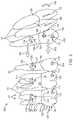
- FIG. 1 Bshows a cross-sectional diagram of an appliance engaging a tooth crown and positioned attachment, in accordance with embodiments
- FIG. 2shows components of an alignment apparatus and corresponding forces, in accordance with embodiments
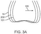
- FIG. 3 Ashows a tooth position prior to completion of a stage of treatment, a target position upon completion of the stage, and a position and orientation of a tooth receiving cavity to complete the stage of treatment, in accordance with embodiments;
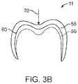
- FIG. 3 Bshows a polymeric shell appliance configured with one or more activation sites to store energy with a tooth at a target position and orientation comprising a non-extruded position and orientation of the tooth, wherein the force is oriented in an intrusive direction and insufficient to intrude the tooth and sufficient to inhibit extrusion of the tooth, in accordance with embodiments.
- FIG. 4shows a method of determining tooth receiving cavities of an appliance away from the target locations, in accordance with embodiments
- FIG. 5shows a simplified block diagram of a data processing system, in accordance with embodiments
- FIG. 6 Ashows an alignment apparatus with an external force producing mechanism, in accordance with embodiments
- FIG. 6 Bshows an alignment apparatus with an external force producing mechanism, in accordance with embodiments.
- FIG. 7shows an alignment apparatus with an external force producing mechanism, in accordance with embodiments.
- a and/or Bencompasses A alone, B alone, and A and B together.
- a “plurality of teeth”encompasses two or more teeth.
- a “moment”encompasses a force acting on an object such as a tooth at a distance from a center of resistance.
- the momentmay be calculated with a vector cross product of a vector force applied to a location corresponding to a displacement vector from the center of resistance, for example.
- the momentmay comprise a vector pointing in a direction.
- a moment opposing another momentmay encompass one of the moment vectors oriented toward a first side of the object such as the tooth and the other moment vector oriented toward an opposite side of the object such as the tooth, for example.
- a “differential moment”encompasses two or more moments coupled to each other to provide opposing moments to one or more teeth.
- the differential momentmay comprise a first moment and a second opposing moment applied to a tooth.
- the differential momentmay comprise a first moment of a first one or more teeth of the arch coupled to a second, opposing moment of a second one or more teeth of the arch.
- the first one or more teeth of the archmay comprise a first segment of the arch and the second one or more teeth of the arch may comprise a second segment of the arch, in which the first moment of the first segment of the arch is coupled to the second, opposing moment of the second segment of the arch.
- the first one or more teethmay comprise a first plurality of adjacent teeth of the first segment of the arch
- the second one or more teethmay comprise a second plurality of adjacent teeth of the second segment of the arch, in which the first moment of the first plurality of adjacent teeth of the arch opposes the second, counter moment of the second plurality of adjacent teeth of the arch.
- a tooth comprising a momentrefers to a tooth with a force acting on the tooth about a center of resistance.
- the forcecan be generated by an appliance coupled to the tooth, either directly or with an attachment on the tooth, and combinations thereof.
- a plurality of posterior teethcomprises counter moments to improve anchoring of the posterior teeth
- one or more anterior teethcomprise a lesser counter moment and are moved toward the plurality of posterior anchor teeth.
- counter moments of one or more of the plurality of posterior teethcan be configured to allow the one or more posterior teeth to move toward the anterior tooth or teeth.
- the moments of a plurality of groups of one or more teethcan be coupled to each other in order to control movement of the teeth, and the moments of the one or more groups of teeth can be coupled to each other in many ways.
- the moments of the groups of one or more teethcan be coupled to each other with offset moments and/or balanced moments in order to provide preferential movement to one or more of the groups of one or more teeth.
- posterior teethcan be provided with a larger counter moment than anterior teeth in order to move the anterior teeth to the posterior teeth.
- the moments and counter moments as disclosed hereinare well suited for moving many types of teeth and conditions of teeth, and are well suited for use with many conditions of teeth.
- the embodiments disclosed hereincan be used to treat one or more of: cant of an occlusal plane, to raise teeth on one side of the mouth and lower teeth on an opposite side of the mouth, en masse expansion of teeth along an arch, closure of an extraction site, intrusion, extrusion, rotation, or tipping, or combinations thereof, for example.
- one or more posterior teethcomprise one or more of a molar, a premolar, or a canine
- one or more anterior teethcomprise one or more of a central incisor, a lateral incisor, a cuspid, a first bicuspid or a second bicuspid.
- posterior teethmay be used herein to refer to the molars and premolars
- anterior teethmay be used herein to refer to the incisors and canines.
- posterior and anteriormay also refer to the relative positioning of groups of one or more teeth, e.g., “posterior teeth” may refer to any teeth that are disposed posteriorly relative to one or more “anterior teeth,” and “anterior teeth” may refer to any teeth that are disposed anteriorly relative to one or more “posterior teeth.”
- the embodiments disclosed hereincan be used to couple groups of one or more teeth to each other.
- the groups of one or more teethmay comprise a first group of one or more anterior teeth and a second group of one or more posterior teeth.
- the first group of teethcan be coupled to the second group of teeth with the polymeric shell appliances as disclosed herein.
- the first group of teethcan be coupled to the second group of teeth in many ways, and in many embodiments the first group of one or more teeth comprises a first moment and a first counter moment, and the second group of one or more teeth comprises a second moment and a second counter moment.
- the first moment and the first counter momentmay comprise a combined first moment and a combined first counter moment of the first group of one or more teeth, and the second moment and the second counter moment may comprise a combined second moment and a combined second counter moment of the second group of teeth.
- the combined first moment, combined first counter moment, combined second moment and combined second counter momentcan be coupled to each other with the polymeric shell appliance in order to move the first group of one or more teeth, the second group of one or more teeth, or combinations thereof.
- each of the first group of one or more teethcomprises a first moment and a counter moment
- each of the second group of one or more teethcomprises a second moment and a second counter moment.
- the first momentcan be generated with a first force to one or more of the first teeth at a first region or location of the first tooth and the counter moment generated with a counter force to the one of the first teeth at a counter location.
- the second momentcan be generated with a second force to one or more of the second teeth at a region of the second tooth and the counter moment generated with a counter force to the one of the second teeth at a counter location.
- the center of resistance of an individual toothcan be located near the bifurcation or trifurcation of the root of the tooth, for example.
- the center of resistancecan be located somewhere between about 25% and about 70% of the distance from the alveolar crest to the apex of the root, for example about 40% of the distance.
- the center of resistance of a group of a segment of teeth comprising a plurality of teethcan be determined in one or more of many ways.
- the center of resistancecan be determined with finite element modeling, published values in the scientific literature, bench testing with experimental loads, mathematical formula and approximations, and/or combinations thereof, for example.
- the center of resistancecan be determined in response to supporting dental structures such as the periodontal ligaments, soft tissue, and bony supporting structures, for example.
- the center of resistance of a group of teethmay change with the direction of movement, a person of ordinary skill in the art can determine the center of resistance in accordance with embodiments disclosed herein.
- the embodiments disclosed hereinare well suited for moving one or more teeth of the first group of one or more teeth or moving one or more teeth of the second group of one or more teeth, or combinations thereof.
- the embodiments disclosed hereinare well suited for combination with one or known commercially available tooth moving components such as attachments and polymeric shell appliances.
- the appliance and one or more attachmentsare configured to move one or more teeth along a tooth movement vector comprising six degrees of freedom, in which three degrees of freedom are rotational and three degrees of freedom are translational.
- Embodiments disclosed hereincan provide differential moment vectors based on a moment and a counter moment to each of a plurality of teeth. The differential moment vector can provide improved accuracy of movement of the teeth and may result in decreased amounts of force to move one or more teeth.
- the present disclosureprovides orthodontic systems and related methods for designing and providing improved or more effective tooth moving systems for eliciting a desired tooth movement and/or repositioning teeth into a desired arrangement.
- a method of moving a plurality of teeth with an appliancecomprises: providing an appliance shaped for placement on the plurality of teeth, the appliance comprising a plurality of tooth receiving cavities shaped to receive each of the plurality of teeth and provide a differential moment to the plurality of teeth in order to move and/or anchor the teeth, the plurality of teeth comprising a first one or more teeth and a second one or more teeth, the first one or more teeth comprising a first counter moment and the second one or more teeth comprising a second counter moment, the first counter moment opposite the second counter moment.
- the differential moment of said each of the plurality of teethcomprises a moment and a counter moment opposite the moment, the moment generated with a force about a center of resistance, the counter moment generated with a counter force about the center of resistance, the counter force opposite the force, the force greater than the counter force for said each of the plurality of teeth in order to move the teeth.
- each of the plurality of tooth receiving cavitiesis shaped and arranged to produce a summed moment comprising a sum of the moment and the counter moment for said each of the plurality of teeth.
- the applianceis shaped to urge a first portion of the first one or more teeth and a second portion of the second one or more teeth away from each other in order to move the first one or more teeth toward the second one or more teeth.
- the appliancecan be shaped to urge a first portion of the first one or more teeth and a second portion of the second one or more teeth away from each other in order to move the first one or more teeth and the second one or more teeth toward each other.
- the first one or more teethcomprise a first plurality of teeth and the appliance comprises a shape to generate the first counter moment with each of the first plurality of adjacent teeth, the first counter moment comprising a combination of similarly oriented moments from said each of the first plurality of adjacent teeth.
- the second one or more teethcomprise a second plurality of teeth and the appliance comprises a shape to generate the second counter moment with each of the second plurality of adjacent teeth, the second counter moment comprising a combination of similarly oriented moments from said each of the second plurality of adjacent teeth.
- the plurality of tooth receiving cavitiesis shaped and arranged to balance the differential moment between the first one or more teeth and the second one or more teeth and to balance the first counter moment and the second counter moment between the first one or more teeth and the second one or more teeth.
- the first one or more teethcomprises an anterior group of one or more teeth and the second one or more teeth comprises a posterior group of one or more teeth, wherein the first counter moment of the anterior group of one or more teeth opposes the second counter moment of the posterior group of one or more teeth.
- the anterior group of one or more teethcan comprise a single anterior tooth, the appliance shaped to generate the first counter moment with the single anterior tooth.
- the posterior group of one or more teethcan comprise a plurality of adjacent posterior teeth, the appliance shaped to generate the second counter moment with the plurality of adjacent posterior teeth.
- the appliancecan be shaped to generate the second counter moment with each of the plurality of adjacent posterior teeth, the second counter moment comprising a combination of similarly oriented moments from said each of the adjacent posterior teeth.
- the first counter momentcan be less than the second counter moment in order to move the anterior group of one or more teeth toward the plurality of adjacent posterior teeth.
- the plurality of adjacent posterior teethcan comprise three adjacent posterior teeth, the appliance shaped to generate the second counter moment with the three adjacent posterior teeth.
- the three adjacent posterior teethcan comprise three adjacent posterior anchor teeth coupled together as a block of teeth having a combined center of resistance away from the center of resistance of each tooth of the three adjacent posterior teeth.
- the first one or more teethcomprises a posterior group of one or more teeth and the second one or more teeth comprises an anterior group of teeth, and the first counter moment of the anterior group of one or more teeth opposes the second counter moment of the anterior group of one or more teeth.
- the group of one or more anterior teethcan comprise a plurality of adjacent anterior teeth and the plurality of adjacent tooth receiving cavities can comprise a plurality of adjacent anterior tooth receiving cavities shaped to generate the first counter moment.
- the methodfurther comprises providing an external force or anchorage producing mechanism coupled to the plurality of teeth, wherein the external force or anchorage producing mechanism is arranged to apply a force and/or anchorage to the posterior group of one or more teeth so as to reduce movement of the posterior group of one or more teeth.
- the force applied to the posterior group of one or more teeth by the external force producing mechanismcan comprise a distal force component.
- the external force or anchorage producing mechanismcan comprise a class II or class III elastic.
- each of the plurality of tooth receiving cavitiescomprises an inner surface profile corresponding to a surface profile of the tooth in order to generate a moment and a counter moment with said each of the plurality of teeth.
- the plurality of tooth receiving cavitiescomprises a first one or more cavities shaped to receive the first one or more teeth and a second one or more cavities shaped to receive the second one or more teeth, the first one or more tooth receiving cavities shaped to generate the first counter moment and the second one or more tooth receiving cavities shaped to generate the second counter moment with the first counter moment opposite the second counter moment.
- the first counter moment of the first one or more teethis sufficient to move first one or more roots of the first one or more teeth toward the second one or more teeth.
- the differential moment to said each of the plurality of teethcomprises a moment and a counter moment opposite the moment, wherein a force at a location generates the moment about a center of resistance and a counter force at a counter location generates the counter moment about the center of resistance for said each of the plurality of teeth and wherein a sum of the force and the counter force comprises a combined overall force to the tooth for said each of the plurality of teeth.
- a combined overall force of the first one or more teethcan urge the first one or more teeth toward the second one or more teeth.
- the combined overall forcecan be lower than each of the force and the counter force for said each of the plurality of teeth in order to move the first one or more teeth toward the second one or more teeth with decreased amounts of force.
- the one or more of the plurality of tooth receiving cavitiescomprise one or more engagement structures shaped to receive one or more attachments and urge the first one or more teeth away from the second one or more teeth with a counter force in order to facilitate movement of the first one or more teeth toward the second one or more teeth.
- the one or more engagement structures shaped to receive the one or more attachmentscan generate a force opposite the counter force to move the first one or more teeth in a target direction toward the second one or more teeth.
- the forcecan be greater than the counter force to move the one or more target teeth in the target direction and the counter force can decrease a total amount of force to the one or more target teeth and generate the first counter moment.
- the appliancecomprises a plurality of structures shaped to receive a plurality of attachments and urge a first tooth away from a second tooth in order to facilitate movement of the first tooth toward the second tooth.
- the appliancecomprises a polymeric shell, the polymeric shell comprising a plurality of activation sites to store energy with a plurality of deflections of the polymeric shell in order to direct movement of the teeth.
- One or more of the plurality of deflectionscan store energy with a force against the tooth, the force can be insufficient to move the tooth in a direction opposite the deflection when the tooth comprises a target position and orientation, and additional deflection can generate sufficient increased force to move the tooth in response to the tooth moving away from the target position and orientation.
- the target position and orientationcan comprise a non-extruded position and orientation of the tooth and the force can be oriented in an intrusive direction and insufficient to intrude the tooth and sufficient to inhibit extrusion of the tooth.
- the target position and orientationcan comprise a non-intruded position and orientation of the tooth corresponding to a stage of the appliance and the force can be oriented in an extrusive direction and insufficient to extrude the tooth and sufficient to inhibit intrusion of the tooth.
- the plurality of teethcomprises a plurality of adjacent teeth and a target tooth to be moved toward the plurality of adjacent teeth, the plurality of appliance cavities shaped to receive each of the plurality of adjacent teeth and the target tooth in order to move the target tooth toward the plurality of adjacent teeth, wherein the plurality of cavities is shaped and arranged to provide opposing forces to the plurality of adjacent teeth and the target tooth in order to distribute forces among the plurality of adjacent teeth and inhibit movement.
- the plurality of adjacent teethcan comprise a plurality of adjacent molars and the target tooth can comprise an anterior tooth retracted toward an extraction site. The target tooth can move in a sagittal direction.
- a useradjusts positions and orientations of the teeth shown on a display with user input for a stage of treatment corresponding to the appliance, wherein each of the plurality of tooth receiving cavities comprises a cavity shape profile corresponding to a tooth shape profile of a tooth to be received in the cavity, and wherein each cavity shape profile is positioned and/or oriented away from a corresponding tooth shape profile position and orientation shown on the display in order to provide activation energy to the appliance when placed on the plurality of teeth.
- each cavity shapematches at least a portion of a surface of the received tooth.
- each cavity shapecan match opposing surfaces of the received tooth in order to engage each of the opposing surfaces of the tooth.
- Each cavity shape profilecan comprise first and second opposing surfaces to engage said each of the opposing surfaces of the tooth, wherein said first and second opposing surfaces are shaped to contact the tooth together along a direction of tooth movement.
- the first one or more teeth and a second one or more teethmove toward each other in order to provide differential space closure to a space extending between the first one or more teeth and the second one or more teeth.
- the first one or more teethcan comprise a plurality of anterior teeth and the second one or more teeth can comprise a plurality of posterior teeth, and the plurality of posterior teeth can comprise a combined center of resistance away from a center of resistance of each of the plurality of posterior teeth.
- the first counter momentcorresponds to a first force to the first one or more teeth from the appliance at a first location about a first center of resistance and the second counter moment corresponds to a second counter force to the second one or more teeth about a second center of resistance.
- the appliancecomprises a polymeric shell appliance.
- the appliancecan comprise a polymeric shell appliance directly manufactured with one or more of 3D printing, stereo lithography, or fused deposition modeling.
- the plurality of teeth receiving cavitiesprovide the differential moment to the plurality of teeth in order to increase anchorage of one or more of the plurality of teeth.
- an appliance shaped for placement on a plurality of teethcomprises a plurality of tooth receiving cavities shaped to receive each of the plurality of teeth and provide a differential moment to the plurality of teeth in order to move and/or anchor one or more teeth of the plurality of teeth, the plurality of tooth receiving cavities comprising a first one or more tooth receiving cavities shaped to receive a first one or more teeth and a second one or more tooth receiving cavities shaped to receive a second one or more teeth, the first one or more tooth receiving cavities shaped to provide a first counter moment to the first one or more teeth, the second one or more tooth receiving cavities shaped to provide a second counter moment to the second one or more teeth, the first counter moment opposite the second counter moment.
- each of the plurality of tooth receiving cavitiesis shaped and arranged to provide the differential moment comprising a moment and a counter moment opposite the moment to a received tooth, the moment generated with a force about a center of resistance, the counter moment generated with a counter force about the center of resistance, the counter force opposite the force, the force greater than the counter force for said each of the plurality of teeth.
- the first one or more tooth receiving cavitiesis shaped and arranged to receive one or more anterior teeth and generate the first counter moment and the second one or more tooth receiving cavities is shaped and arranged to receive posterior teeth and generate the second counter moment, the second counter moment greater than the first counter moment.
- each of the plurality of tooth receiving cavitiesis shaped and arranged to produce a summed moment comprising a sum of the moment and the counter moment for said each of the plurality of teeth.
- the first one or more tooth receiving cavitiescomprises a plurality of adjacent teeth receiving cavities shaped and arranged to receive a plurality of adjacent teeth, wherein the first counter moment comprises a combined counter moment of the plurality of adjacent teeth about a center of resistance away from a center of resistance of said each of the plurality of adjacent teeth.
- the second one or more tooth receiving cavitiescomprises a plurality of adjacent teeth receiving cavities shaped and arranged to receive a plurality of adjacent teeth, wherein the second counter moment comprises a combined counter moment of the plurality of adjacent teeth about a center of resistance away from a center of resistance of said each of the plurality of adjacent teeth.
- each of the plurality of tooth receiving cavitiescomprises a cavity shape profile corresponding to a tooth shape profile of a tooth to be received in the cavity, wherein each cavity shape profile is positioned and/or oriented away from a corresponding tooth shape profile position and orientation in order to provide activation energy to the polymeric shell appliance when placed on the plurality of teeth.
- Each cavity shape profilecan comprise first and second opposing surfaces to engage said each of the opposing surfaces of the tooth and said first and second opposing surfaces can be shaped to contact the tooth together along a direction of tooth movement.
- the polymeric shell applianceis shaped to urge a first portion of the first one or more teeth and a second portion of the second one or more teeth away from each other in order to move the first one or more teeth toward the second one or more teeth.
- the polymeric shell appliancecan be shaped to urge a first portion of the first one or more teeth and a second portion of the second one or more teeth away from each other in order to move the first one or more teeth and the second one or more teeth toward each other.
- the first one or more teethcan comprise a first plurality of teeth and the polymeric shell appliance can comprise a shape to generate the first counter moment with each of the first plurality of adjacent teeth, the first counter moment comprising a combination of similarly oriented moments from said each of the first plurality of adjacent teeth.
- the second one or more teethcan comprise a second plurality of teeth and the polymeric shell appliance can comprise a shape to generate the second counter moment with each of the second plurality of adjacent teeth, the second counter moment comprising a combination of similarly oriented moments from said each of the second plurality of adjacent teeth.
- the plurality of tooth receiving cavitiesis shaped and arranged to balance the differential moment between the first one or more teeth and the second one or more teeth and to balance the first counter moment and the second counter moment between the first one or more teeth and the second one or more teeth.
- the first one or more teethcan comprise an anterior group of one or more teeth and the second one or more teeth can comprise a posterior group of teeth, wherein the first counter moment of the anterior group of one or more teeth opposes the second counter moment of the posterior group of one or more teeth.
- the posterior group of one or more teethcan comprise a plurality of adjacent posterior teeth, the polymeric shell appliance being shaped to generate the second counter moment with the plurality of adjacent posterior teeth.
- the plurality of adjacent posterior teethcan comprise three adjacent posterior teeth, the polymeric shell appliance being shaped to generate the second counter moment with the three adjacent posterior teeth.
- the three adjacent posterior teethcan comprise three adjacent posterior anchor teeth coupled together as a block of teeth having a combined center of resistance away from the center of resistance of each tooth of the three adjacent posterior teeth.
- the anterior group of one or more teethcan comprise a single anterior tooth, the polymeric shell appliance being shaped to generate the first counter moment with the single anterior tooth.
- the polymeric shell applianceis shaped to generate the second counter moment with each of the plurality of adjacent posterior teeth, the second counter moment comprising a combination of similarly oriented moments from said each of the adjacent posterior teeth.
- the first counter momentcan be less than the second counter moment in order to move the anterior group of one or more teeth toward the plurality of adjacent posterior teeth.
- the first one or more teethcomprises a posterior group of one or more teeth and the second one or more teeth comprises an anterior group of teeth, wherein the first counter moment of the anterior group of one or more teeth opposes the second counter moment of the anterior group of one or more teeth.
- the group of one or more anterior teethcan comprise a plurality of adjacent anterior teeth and the plurality of adjacent tooth receiving cavities can comprise a plurality of adjacent anterior tooth receiving cavities shaped to generate the first counter moment.
- the appliancesfurther comprises an external force or anchorage producing mechanism coupled to the plurality of teeth, wherein the external force or anchorage producing mechanism is arranged to apply a force and/or anchorage to the posterior group of one or more teeth so as to reduce movement of the posterior group of one or more teeth.
- the force applied to the posterior group of one or more teeth by the external force producing mechanismcan comprise a distal force component.
- the external force or anchorage producing mechanismcan comprise a class II or class III elastic.
- each of the plurality of tooth receiving cavitiescomprises an inner surface profile corresponding to a surface profile of the tooth in order to generate a moment and a counter moment with said each of the plurality of teeth.
- the plurality of tooth receiving cavitiescomprises a first one or more cavities shaped to receive a first one or more teeth and a second one or more cavities shaped to receive a second one or more teeth, the first one or more tooth receiving cavities shaped to generate the first counter moment and the second one or more tooth receiving cavities shaped to generate the second counter moment with the first counter moment opposite the second counter moment.
- the first counter moment of the first one or more teethis sufficient to move first one or more roots of the first one or more teeth toward the second one or more teeth.
- the differential moment to said each of the plurality of teethcomprises a moment and a counter moment opposite the moment, wherein a force at a location generates the moment about a center of resistance and a counter force at a counter location generates the counter moment about the center of resistance for said each of the plurality of teeth and wherein a sum of the force and the counter force comprises a combined overall force to the tooth for said each of the plurality of teeth.
- a combined overall force of the first one or more teethcan urge the first one or more teeth toward the second one or more teeth.
- the combined overall forcecan be lower than each of the force and the counter force for said each of the plurality of teeth in order to move the first one or more teeth toward the second one or more teeth with decreased amounts of force.
- one or more of the plurality of tooth receiving cavitiescomprises one or more engagement structures shaped to receive one or more attachments and urge the first one or more teeth away from the second one or more teeth with a counter force in order to facilitate movement of the first one or more teeth toward the second one or more teeth.
- the one or more engagement structures shaped to receive the one or more attachmentscan generate a force opposite the counter force to move the first one or more teeth in a target direction toward the second one or more teeth, and the force can be greater than the counter force to move the one or more target teeth in the target direction, and the counter force can decrease a total amount of force to the one or more target teeth and generates the first counter moment.
- the appliancefurther comprises the one or more attachments.
- the polymeric shell appliancecomprises a plurality of engagement structures shaped to receive a plurality of attachments and urge a first tooth away from a second tooth in order to facilitate movement of the first tooth toward the second tooth.
- the appliancefurther comprises the plurality of attachments.
- the appliancecomprises a polymeric shell, the polymeric shell comprising a plurality of activation sites to store energy with a plurality of deflections of the polymeric shell in order to direct movement of the teeth.
- One or more of the plurality of deflectionscan store energy with a force against the tooth, wherein the force is insufficient to move the tooth in a direction opposite the deflection when the tooth comprises a target position and orientation corresponding to a stage of the polymeric shell, and wherein additional deflection generates sufficient increased force to move the tooth in response to the tooth moving away from the target position and orientation.
- the target position and orientationcan comprise a non-extruded position and orientation of the tooth and the force can be oriented in an intrusive direction and insufficient to intrude the tooth and sufficient to inhibit extrusion of the tooth.
- the target position and orientationcan comprise a non-intruded position and orientation of the tooth and the force can be oriented in an extrusive direction and insufficient to extrude the tooth and sufficient to inhibit intrusion of the tooth.
- the plurality of teethcomprises a plurality of adjacent teeth and a target tooth to be moved toward the plurality of adjacent teeth, the plurality of polymeric shell appliance cavities shaped to receive each of the plurality of adjacent teeth and the target tooth in order to move the target tooth toward the plurality of adjacent teeth and wherein the plurality of cavities is shaped and arranged to provide opposing forces to the plurality of adjacent teeth and the target tooth in order to distribute forces among the plurality of adjacent teeth and inhibit movement.
- the plurality of adjacent teethcan comprise a plurality of adjacent molars and the target tooth can comprise an anterior tooth retracted toward an extraction site. The target tooth can move in a sagittal direction.
- a useradjusts positions and orientations of the teeth shown on a display with user input for a stage of treatment corresponding to the polymeric shell appliance
- each of the plurality of tooth receiving cavitiescomprises a cavity shape profile corresponding to a tooth shape profile of a tooth to be received in the cavity, and wherein each cavity shape profile is positioned and/or oriented away from a corresponding tooth shape profile position and orientation shown on the display in order to provide activation energy to the polymeric shell appliance when placed on the plurality of teeth.
- Each cavity shape profilecan match opposing surfaces of the received tooth in order to engage each of the opposing surfaces of the tooth.
- Each cavity shape profilecan comprise first and second opposing surfaces to engage said each of the opposing surfaces of the tooth and said first and second opposing surfaces can be shaped to contact the tooth together along a direction of tooth movement.
- the applianceis configured to move the first one or more teeth and the second one or more teeth toward each other in order to provide differential space closure to a space extending between the first one or more teeth and the second one or more teeth.
- the first one or more teethcan comprise a plurality of anterior teeth and the second one or more teeth can comprise posterior teeth and the plurality of posterior teeth can comprise a combined center of resistance away from a center of resistance of each of the plurality of posterior teeth.
- the first counter momentcorresponds to a first force to the first one or more teeth from the appliance at a first location about a first center of resistance and the second counter moment corresponds to a second counter force to the second one or more teeth about a second center of resistance.
- the appliancecomprises a polymeric shell appliance.
- the appliancecan comprise a polymeric shell appliance directly manufactured with one or more of 3D printing, stereo lithography, or fused deposition modeling.
- the plurality of teeth receiving cavitiesprovide the differential moment to the plurality of teeth in order to increase anchorage of one or more of the plurality of teeth.
- a system to generate a plurality of appliances for moving a plurality of teeth of a subjectcomprises: an input; a display; and a processor coupled to the display and the input.
- the processorcan comprise instructions embodied on a tangible medium to: display the plurality of teeth of the subject at a plurality of stages of a treatment, each stage corresponding to an appliance of the plurality of appliances, adjust each of the plurality of teeth on the display to a position and an orientation in response to user input to position the teeth at each of a plurality of stages of the treatment, and determine a shape profile of a polymeric shell appliance shaped for placement on the plurality of teeth at a corresponding stage of treatment, the polymeric shell appliance comprising a plurality of tooth receiving cavities, each of the plurality of tooth receiving cavities comprising a shape profile corresponding to a shape profile of a received tooth, wherein the shape profile of said each of the plurality of tooth receiving cavities is one or more of located or oriented away from the position and orientation shown on the display for
- the processorcomprises instructions to include an attachment on one or more of the plurality of teeth in response to a force to the one or more of the plurality of teeth.
- the processorcomprises instructions to generate one or more attachment engaging structures on the polymeric shell appliance.
- the shape profile of said each of the plurality of tooth receiving cavitiesmatches the shape profile of the received tooth.
- the shape profile of said each of the plurality of tooth receiving cavitiescan be configured to engage opposing surfaces of the received tooth.
- Each cavity shape profilecan comprise first and second opposing surfaces to engage said each of the opposing surfaces of the received tooth and said first and second opposing surfaces can be shaped to contact the tooth together along a direction of tooth movement.
- the processorcomprises instructions to determine a center of resistance of each of a plurality of individual teeth, wherein the processor comprises instructions to determine a center of resistance of a group of adjacent teeth, in which the center of resistance of the group of adjacent teeth is located away from a center of resistance of each of the group of adjacent teeth.
- the processorcomprises instructions to determine a differential moment about a center of resistance for each of the plurality of teeth.
- the differential momentcan comprise a first moment about the center of resistance in response to a first force and a second moment about the center of resistance in response to a second force opposite the first force for said each of the plurality of teeth.
- the differential momentcan be related to tipping along a direction of tooth movement for said each of the plurality of teeth.
- the processorcomprises instructions to generate an appliance as in any one of the embodiments herein.
- a method of moving teeth with a polymeric shell appliancecomprises: providing a first force to a first crown of a first tooth and a second force to a second crown of a second tooth in order to move the first tooth toward the second tooth, the force resulting in a first moment on the first tooth and a second moment on the second tooth; and providing a first counter force to the first crown opposite the first force and a second counter force to the second crown opposite the second force in order to inhibit the first moment in the first tooth and the second moment in the second tooth, the first force greater than the first counter force and the second force greater than the second counter force in order to move one or more of the first tooth toward the second tooth or the second tooth toward the first tooth.
- a methodcomprises providing a polymeric shell appliance.
- the polymeric shell applianceis configured to provide: a first force to a first crown of a first tooth and a second force to a second crown of a second tooth in order to move the first tooth toward the second tooth, the force resulting in a first moment on the first tooth and a second moment on the second tooth; and a first counter force to the first crown opposite the first force and a second counter force to the second crown opposite the second force in order to inhibit the first moment in the first tooth and the second moment in the second tooth, the first force greater than the first counter force and the second force greater than the second counter force in order to move one or more of the first tooth toward the second tooth or the second tooth toward the first tooth.
- the polymeric shell applianceis configured to couple the first force to the first crown and the second force to the second crown with the polymeric shell extending between the first crown and the second crown and the polymeric shell appliance is configured to provide the first counter force to the first crown with a first attachment on the first crown engaging the polymeric shell appliance and to provide the second counter force to the second crown with a second attachment on the second crown engaging the polymeric shell.
- the polymeric shell applianceis shaped to engage the first crown at a first location to generate the first force and to engage the second crown at a second location to generate the second force.
- the polymeric shell applianceis configured to couple the first force to the first crown at a first location and the second force to the second crown at a second location, wherein the polymeric shell appliance is configured to couple the first counter force to the first crown at a third location and the second counter force to the second crown at a fourth location, the first location closer to the gingiva than the third location and the second location closer to the gingiva than the second location.
- the polymeric shell applianceis configured to generate a first counter moment with the first counter force and a second counter moment with the second counter force with the first counter moment less than the second counter moment in order to encourage the first tooth to move toward the second tooth.
- the first toothcomprises an anterior tooth and the second tooth comprises a posterior tooth.
- the first toothcomprises a posterior tooth and the second tooth comprises an anterior tooth.
- the posterior toothcomprises one or more posterior teeth comprising one or more of a molar, a premolar, or a canine
- the anterior toothcomprises one or more anterior teeth comprising one or more of a central incisor, a lateral incisor, a cuspid, a first bicuspid, or a second bicuspid.
- one or more of the one or more anterior teeth or the one or more of the posterior teethare moved together with en masse separation along an arch.
- the methodfurther comprises providing an appliance as in any one of the preceding claims.
- a method of moving a first tooth toward a second toothcomprises applying a first force to the first tooth directed away from the second tooth and a second force to the second tooth directed away from first tooth in order to inhibit rotation of the first and the second tooth as one or more of the first tooth or the second tooth are urged toward the other tooth.
- an appliance for moving one or more teethcomprises: a plurality of tooth receiving cavities to engage a plurality of teeth comprising a first tooth and a second tooth, the plurality of tooth receiving cavities comprising a first cavity shaped to receive the first tooth and a second cavity shaped to receive the second tooth, the first cavity and the second cavity arranged to urge the first tooth in a first direction and the second tooth in a second direction; a first engagement structure to engage a first tooth of the plurality of teeth; and a second engagement structure to engage a second tooth of the plurality of teeth; wherein the first engagement structure and the second engagement structure are arranged to urge the first tooth in a third direction opposite the first direction and the second tooth in a fourth direction opposite the second direction.
- first toothcomprises a first attachment and the first engagement structure comprises a first attachment engaging structure
- the second toothcomprises a second attachment and the second engagement structure comprises a second attachment engaging structure
- the first engagement structure, the second engagement structure, the first tooth receiving cavity and the second tooth receiving cavitycan be arranged to provide a first counter moment to the first tooth to decrease rotation of the first tooth and a second counter moment to decrease rotation of the second tooth.
- the first engagement structurecan comprise one or more of a first attachment engaging structure, a first power ridge, or a first shape profile corresponding to a surface of the first tooth and the second engagement structure can comprise one or more of a second attachment engaging structure, a second power ridge, or a second shape profile corresponding to the surface of the first tooth.
- the appliancecomprises the appliance of any one of the embodiments provided herein.
- a system to generate a plurality of appliances for moving a plurality of teeth of a subjectcomprises: an input; a display; and a processor coupled to the display and the input.
- the processorcomprises instructions embodied on a tangible medium to: display the plurality of teeth of the subject at a plurality of stages of a treatment, each stage corresponding to an appliance of the plurality of appliances; adjust each of the plurality of teeth on the display in response to user input to position the teeth at each stage of the treatment; and determine a shape profile of a polymeric shell appliance shaped for placement on the plurality of teeth, the polymeric shell appliance comprising a plurality of tooth receiving cavities shaped to receive each of the plurality of teeth and provide a differential moments to each of the plurality of teeth in order to move the teeth.
- the processorcomprises instructions to determine the shape profile of the appliance with a plurality of attachment engaging structures shaped to engage a plurality of attachments with the plurality of attachments and the plurality of attachment engaging structures shaped and arranged to engage each other and provide the plurality of differential moments to said each of the plurality of teeth.
- the processorcomprises instructions to generate an appliance as in any one of the embodiments herein.
- the processorcomprises instructions to directly fabricate the polymeric shell appliance with one or more of 3D printing, fused deposition modeling, or stereo lithography.
- an appliancecomprising a polymeric shell appliance
- the embodiments disclosed hereinare well suited for use with many appliances that receive teeth, for example appliances without one or more of polymers or shells.
- the appliancecan be fabricated with one or more of many materials such as metal, glass, reinforced fibers, carbon fiber, composites, reinforced composites, aluminum, biological materials, and combinations thereof for example.
- the appliancecan be shaped in many ways, such as with thermoforming or direct fabrication as described herein, for example.
- the appliancecan be fabricated with machining such as an appliance fabricated from a block of material with computer numeric control machining.
- Orthodontic systems of the present disclosurecan include tooth attachments and one or more orthodontic appliances that engage the attachments when worn by a patient.
- Appliances having teeth receiving cavities that receive and reposition teeth, e.g., via application of force due to appliance resiliency,are generally illustrated with regard to FIG. 1 A .
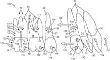
- FIG. 1 Ashows one exemplary adjustment polymeric shell appliance 11 which is worn by the patient in order to achieve an incremental repositioning of each of a plurality of teeth 10 in the jaw.
- the appliancecan include a shell (e.g., polymeric shell) having teeth-receiving cavities that receive and resiliently reposition the teeth.
- Similar appliancesincluding those utilized in the InvisalignTM System, are described in numerous patents and patent applications assigned to Align Technology, Inc.
- Appliances according to the present disclosurecan be designed to engage one or more attachments positioned on a tooth of the patient, as further described below.
- tooth attachmentscan be designed, oriented, and/or located on a patient's tooth to precisely control the moments produced on a patient's tooth as the appliance is worn by the patient.
- Customized design and use in orthodontic treatment as described hereincan advantageously improve effectiveness of treatment and clinical results by more precisely applying force vectors of necessary magnitude and direction for desired movement.
- Orthodontic systems of the present disclosure including appliances and tooth attachments as describedfurther provide an efficient force distribution mechanism that can more effectively reduce unwanted force and moment.
- the plurality of teeth 10may comprise one or more attachments 102 .
- the polymeric shell appliance 11comprises a plurality of tooth receiving cavities 101 shaped to receive each of the plurality of teeth. Each of the plurality of tooth receiving cavities comprises an inner surface profile shaped to correspond to the exterior surface of the received tooth. In many embodiments, the interior surface of the polymeric shell appliance matches at least a portion of the surface of the received tooth, such as opposing surfaces of the profile of the received tooth.
- the polymeric shell appliance 11may comprise one or more engagement structures 104 to engage the one or more attachments. In many embodiments, the one or more engagement structures are configured to provide force to the tooth when the appliance engages the one or more attachments.
- the one or more engagement structures 104can be configured in many ways to provide force in a predetermined direction to the one or more attachments 102 .
- the one or more engagement structuresmay comprise a structure configured to receive the one or more attachments 102 with at least some deflection and/or distortion of the engagement structure 104 in order to apply force to the attachment and tooth.
- the engagement structure 104may comprise one or more protrusions 105 , for example, configured to engage the attachment.
- the engagement structure 104comprises a cavity 106 shaped to receive the attachment.
- the one or more protrusions 105protrudes from the polymeric shell inside the cavity 106 with a shape to engage a flat surface of the attachment and apply force in a direction substantially normal to the flat surface of the attachment.
- Tooth attachment devices for delivering forces similar to the attachment of FIG. 1 B and suitable for incorporation in accordance with embodiments as disclosed hereinare described in U.S. application Ser. No. 12/623,340, filed on Nov. 20, 2009, published as U.S. 2010/0138025 on Jun. 3, 2010, entitled “Orthodontic systems and methods including parametric attachments,” the entire disclosure of which is incorporated herein by reference.
- Methods and systems for determining dental aligner geometries suitable for incorporation in accordance with embodiments disclosed hereinare described in U.S. application Ser. No. 13/865,091, filed on Apr. 17, 2013, published as U.S. 2013/0230818, entitled “Method and system for optimizing dental aligner geometry,” the entire disclosure of which is incorporated herein by reference.
- the attachmentis coupled to a surface of the tooth on the tooth crown and can couple with or engage a dental appliance or aligner as illustrated in FIG. 1 A when the appliance is worn by the patient.
- the applianceengages the tooth crown and attachment, with interaction/contact between an activator, e.g., one or more surfaces or portions of the internal cavity of the appliance, and corresponding surfaces/portions of the tooth attachment and/or tooth crown to apply a system of forces for eliciting tooth movement.
- an activatore.g., one or more surfaces or portions of the internal cavity of the appliance
- corresponding surfaces/portions of the tooth attachment and/or tooth crownto apply a system of forces for eliciting tooth movement.
- Various tooth movementscan be accomplished, as further noted below.
- an appliancecan be designed and/or provided as part of a set or plurality of appliances and treatment can be administered according to a treatment plan.
- each appliancemay be configured so that one or more tooth-receiving cavities have a geometry corresponding to an intermediate or final tooth arrangement intended for the appliance.
- Appliance geometriescan be further designed or modified (e.g., modified to accommodate or operate in conjunction with tooth attachments) so as to apply a desired force or system of forces to the patient's teeth and elicit a desired tooth movement and gradually reposition teeth to an intended arrangement.
- the patient's teethare progressively repositioned from their initial tooth arrangement toward a final tooth arrangement by placing a series of incremental position adjustment appliances over the patient's teeth.
- the adjustment appliancescan be generated all at the same stage or in sets or batches, e.g., at the beginning of a stage of the treatment, and the patient wears each appliance until the pressure of each appliance on the teeth can no longer be felt.
- a plurality of different appliancese.g., set
- the appliancesare generally not affixed to the teeth and the patient may place and replace the appliances at any time during the procedure.
- the final appliance or several appliances in the seriesmay have a geometry or geometries selected to overcorrect the tooth arrangement, i.e., have a geometry which would (if fully achieved) move individual teeth beyond the tooth arrangement which has been selected as the “final.”
- Such over-correctionmay be desirable in order to offset potential relapse after the repositioning method has been terminated, e.g., to permit movement of individual teeth back toward their pre-corrected positions.
- Over-correctionmay also be beneficial to speed the rate of correction, e.g., by having an appliance with a geometry that is positioned beyond a desired intermediate or final position, the individual teeth will be shifted toward the position at a greater rate. In such cases, the use of an appliance can be terminated before the teeth reach the positions defined by the appliance.
- Orthodontic appliancessuch as the appliance illustrated in FIG. 1 A , impart forces to the crown of a tooth and/or an attachment positioned on the tooth at each point of contact between a tooth receiving cavity of the appliance and received tooth and/or attachment.
- the magnitude of each of these forces and their distribution on the surface of the toothdetermines the type of orthodontic tooth movement which results.
- Types of tooth movementsare conventionally delineated as extrusion, intrusion, rotation, tipping, translation and root movement. Tooth movement of the crown greater than the movement of the root is referred to as tipping. Equivalent movement of the crown and root is referred to as translation. Movement of the root greater than the crown is referred to as root movement. Tooth movements may be in any direction in any plane of space, and may comprise one or more of rotation or translation along one or more axes.
- the appliances hereinare used to reposition one or more of the patient's teeth in order to treat an orthodontic condition and/or achieve a desired tooth arrangement.
- an orthodontic appliance as described hereincan be used to reposition teeth in order to reduce the size of a space between teeth, also known as “space closure.”
- a spacemay be present in a patient's arch due to extraction of one or more teeth, such as a first bicuspid extraction or a second bicuspid extraction.
- Space closuremay be performed by repositioning one or more teeth near the extraction site, e.g., by moving one or more teeth anterior to the extraction site in a posterior direction, by moving one or more teeth posterior to the extraction site in an anterior direction, or a combination thereof.
- space closureinvolves moving one or more anterior teeth towards the space while maintaining the posterior teeth in their current locations.
- space closurecan involve moving one or more posterior teeth towards the space while maintaining the anterior teeth in their current locations.
- one or more anterior teeth and one or more posterior teethare moved towards each other in order to close a space.
- the anterior teethmay be moved prior to, concurrently with, or after moving the posterior teeth, and the distance over which the anterior teeth are moved can be greater than, less than, or equal to the distance over which the posterior teeth are moved.
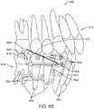
- FIG. 2shows components of an alignment apparatus 100 and corresponding forces.
- the alignment apparatus 100may comprise one or more of the attachments and polymeric shell appliances configured and arranged to provide teeth moving forces as described herein.
- Each tooth of the plurality of teeth 10comprises a root 12 and a crown 14 , and the polymeric appliance (omitted for clarity) can apply forces to the crown and/or attachments on the crown in order to move each tooth.
- Each tooth of the plurality of teethcan move with respect to a center of resistance.
- the plurality of teeth 10may comprise two or more of any teeth of the mouth.
- the plurality of teeth 10may comprise one or more of a plurality of posterior teeth 20 such as a plurality of molars or bicuspids or combinations thereof.
- the plurality of posterior teeth 20may comprise one or more of a bicuspid 26 , a first molar 24 or a second molar 22 , for example.
- the plurality of posterior teethmay comprise a third molar comprising a wisdom tooth, for example.
- the plurality of teeth 10may comprise one or more of a plurality of anterior teeth 30 .
- the plurality of anterior teethmay comprise one or more of a bicuspid, a cuspid (canine), or incisor, for example.
- the plurality of anterior teeth 30comprises a cuspid 32 (canine), and one or more adjacent incisors, such as incisor 34 and incisor 36 .
- each of the plurality of attachmentscomprises a flat surface to engage a corresponding respective engagement structure of the aligner (not shown).
- the engagement structure of the alignermay comprise a protrusion that engages the flat surface in order to impart force from the polymeric shell appliance to the attachment and tooth with the attachment.
- the protrusion of the engagement structurecan be configured in many ways, and may comprise a protrusion on an inner surface of an attachment receiving cavity of the appliance or a ball shaped structure that engages the flat surface, for example.
- the attachment engaging structure of the applianceengages the attachment so as to exert force in a direction substantially normal to the flat surface of the attachment.
- one or more teethare moved to fill an extraction site with a movement in a target direction 105 .
- the target direction 105can extend in any direction, in many embodiments the target direction 105 extends along a sagittal direction (e.g., along a mesial-distal direction).
- the amount of tipping and/or counter rotation of the teethcan be controlled with the size and shape of the appliance, engagement structures of the appliance, and/or attachments, in order to direct movement of one or more teeth with appropriate amounts of force.
- the tooth rootwhen moving a tooth in order to perform space closure or other orthodontic treatments, it is desirable to move the tooth root concurrently with the tooth crown, such that the tooth translates along the target direction with little or no tipping, also known as a “bodily movement” of the tooth.
- Tipping of a toothmay occur when the appliance applies force primarily to the tooth crown and/or when the amount of force on the tooth crown exceeds a certain threshold value.
- each toothcomprises a center of resistance to forces applied to the tooth, and the tooth may rotate about the center of resistance, or approximately rotate in three dimensions about the center of resistance.
- the center of resistance of the toothmay be located away from the tooth crown such that application of force onto the crown results in a moment to the tooth about the center of resistance that elicits tooth rotation.
- the first molar 24may comprise a center of resistance 25 located near the trifurcation of the roots.
- the second molar 22may comprise a center of resistance 23 located near the trifurcation of the roots.
- the bicuspid 26may comprise a center of resistance 27 , for example.
- the cuspid 32may comprise a center of resistance 33 .
- Each of the incisor 34 and the incisor 36may comprise a center of resistance. The location of each of the centers of resistance of the plurality of teeth as described herein may correspond to a center of resistance known to a person of ordinary skill the art.
- a target tooth to be movedsuch as cuspid 32 receives a force from the polymeric shell appliance, which can be a direct force from the surface of the interior of the shell or indirect force through an attachment, or combinations thereof.
- attachment 140can be optionally placed on the tooth 32 in order to direct the tooth 32 with a planned movement.
- Engagement of attachment 140 with polymeric shell appliance 11e.g., via an engagement structure located on polymeric shell appliance 11 ) can result in a force vector to the attachment 140 and tooth as indicated with arrow 141 .
- a moment 146 about the center of resistancecan result.
- the moment 146can result in rotation of tooth 32 , e.g., tipping.
- the appliances hereinare shaped to modify the force system applied to the tooth so as to elicit translational tooth movement with little or no tipping movement.
- the appliances hereincan be shaped to reduce the amount of force applied to the crown, e.g., to within a range from about 0.5 N to about 3 N.
- Modification of the force systemcan be achieved by modifying the shape of a tooth receiving cavity, use of attachments and attachment engagement structures, use of external force producing mechanisms such as elastics, or combinations thereof, as discussed above and herein.
- the appliances hereincan be shaped to modify the energy distribution on the tooth so as to elicit translational tooth movement with little or no tipping movement.
- the appliances hereincan be shaped to distribute energy onto the tooth roots as well as onto the tooth crown. Modification of the energy distribution can be achieved by modifying the shape of a tooth receiving cavity, use of attachments and attachment engagement structures, use of external force producing mechanisms such as elastics, or combinations thereof, as discussed above and herein.
- the appliances hereinare shaped to apply a counter moment onto the tooth that opposes the moment that would otherwise produce tooth rotation, such that the movement of a tooth is provided with a differential moment between the moment and the counter moment.
- the counter momentcan be produced by modifying a position and/or orientation of the tooth receiving cavity relative to the position and/or orientation of the corresponding received tooth such that when the appliance is worn by the patient, the tooth receiving cavity applies the counter moment onto the tooth.
- an attachment on a toothis provided to generate a counter moment, such that the movement of a tooth is provided with a differential moment between the moment and the counter moment.
- the counter momentcan be generated by interaction between the attachment and an engagement structure located on the appliance when the appliance is worn.
- the attachment provided to generate the counter momentis located farther away from the center of resistance than the locus of engagement of the attachment or crown surface that urges the target tooth in the target direction, such that the force vector in the target direction is greater than the counter force in the opposite direction in order to generate the differential moment and urge the target tooth in the target direction.
- a counter moment 136can be provided with an attachment 130 or directed engagement of the tooth with the polymeric shell appliance 11 or combinations thereof, which generates a force vector as shown with arrow 131 , opposite the force vector of attachment 140 shown with arrow 141 .
- the attachment 140 that urges the tooth 32 in target direction 105is located closer to the center of resistance 33 and gingiva than the counter attachment 130 , such that counter moment 136 can approximate moment 146 in order to control rotation of tooth 32 as the tooth moves along target direction 105 .
- counter moment 136can be less than moment 146 to allow the tooth to tip with rotation in the target direction 105 , greater than moment 146 in order to rotate the crown away from target direction 105 , or similar to moment 146 in order to maintain an orientation of tooth 32 when the tooth moves along target direction 105 .
- the appliance 11 comprising the polymeric shellcomprises engagement structures to engage the attachments, and the locations and shapes of the engagement structures can be arranged to provide suitable amounts of counter forces in order to provide counter moments to direct tooth movement along a target path.
- a posterior most toothcomprises a substantial exposed surface 16 suitable for engagement with the polymeric appliance.
- the polymeric shell appliance 11can generate force along the posterior surface of the crown at a locus of engagement as indicated with arrows 122 .
- the anteriorly directed force indicated with arrows 122generates a moment 126 about the center of resistance 23 of second molar 22 , for example.
- the force of the appliance indicated with arrows 122generates a moment 127 around the center of resistance 25 of first molar 24 , and a moment 128 about the center of resistance 27 of the bicuspid 26 , for example.
- One or more of the plurality of posterior teethmay have an attachment placed thereon to generate a counter moment.
- Attachment 110can generate a counter force as indicated with arrow 111 opposite the force indicated with arrows 122 in order to generate a counter moment 116 .
- the counter moment 116can be greater than moment 126 , such that the crown of second molar 22 is rotated away from first molar 24 , for example with the differential moment resulting from the sum of moment 126 with counter moment 116 .
- counter moment 116can be less than moment 126 and also inhibit rotation of second molar 22 toward first molar 24 .
- the moment and counter moment of each toothcan be determined based on the amount of force applied to the tooth and the distance from the center of resistance to the location of the force along the elongate axis of the tooth.
- the force shown with arrows 122is applied at distance 160 along the elongate axis of the tooth from the center of resistance 23 .
- the counter force shown with arrows 111is applied at a distance 162 from the center of resistance 23 .
- the moment 126approximately equals the product of the distance 160 and the force represented by arrows 122 .
- the counter moment 112approximately equals the product of distance 162 and the counter force on attachment 110 represented by arrow 111 .
- a person of ordinary skill in the artwill recognize may ways to determine the moments as described herein, for example with finite element modeling and integrating the moments at a plurality of positions relative to the center of resistance along the tooth.
- Attachment 112can generate a counter force as indicated with arrow 113 opposite the force indicated with arrows 122 in order to generate a counter moment 117 .
- the counter moment 117can be greater than moment 127 , such that the crown of first molar 24 is rotated away from bicuspid 26 , for example with the differential moment resulting from the sum of moment 127 with counter moment 117 .
- counter moment 117can be less than moment 127 and also inhibit rotation of first molar 24 toward bicuspid 26 .
- Attachment 114can generate a counter force as indicated with arrow 115 opposite the force indicated with arrows 122 in order to generate a counter moment 118 .
- the counter moment 118can be greater than moment 128 , such that the crown of bicuspid 26 is rotated away from the target tooth comprising cuspid 32 , for example with the differential moment resulting from the sum of moment 128 with counter moment 118 .
- counter moment 118can be less than moment 128 and also inhibit rotation of bicuspid 26 toward the target tooth comprising cuspid 32 .
- a ratiois defined between the magnitude of the total moment applied to the tooth and the amount of force applied to the tooth along the targeted movement direction, referred to herein as the “moment-force ratio.”
- the moment-force ratio for tooth 32is defined as the ratio between the sum of moment 146 and counter moment 136 , and force 141 .
- the value of the moment-force ratiomay determine the resultant movement of the tooth, e.g., whether the tooth translates, rotates, or both.
- the appropriate moment-force ratio to be applied to a tooth in order to produce translation while reducing rotationvaries based on the characteristics of the particular tooth, e.g., tooth size, complexity of the root structure, and/or location of the center of resistance.
- the moment-force ratio to produce translation with little or no rotationcan be within a range from about 4 mm to about 10 mm.
- the moment-force ratio to produce translation with little or no rotationcan be within a range from about 6 mm to about 15 mm.
- first group of one or more teethwhile maintaining a second group of one or more teeth (“anchoring teeth”) in their current arrangement.
- space closuremay be performed by retracting one or more anterior teeth while anchoring one or more posterior teeth, or by advancing one or more posterior teeth while anchoring one or more anterior teeth.
- one or more of the plurality of posterior teeth 20can be configured with differential moments in order to control orientation of the one or more teeth.
- counter moments of posterior teethare arranged to inhibit movement of the posterior teeth.
- the plurality of posterior teeth 20comprises a block of adjacent teeth configured to anchor the appliance and move the target tooth with little or no movement of the plurality of adjacent anchor teeth.
- one or more of the plurality of posterior teeth 20can be configured to move toward the target tooth, for example.
- an orthodontic applianceis shaped to apply a moment to a first group of one or more teeth to be moved (e.g., to close a space) and apply a counter moment to a second group of one or more anchoring teeth, thereby producing a differential moment between the first and second groups of teeth.
- a differential momentcan be produced by modifying the shape of one or more tooth receiving cavities, use of attachments and attachment engagement structures, use of external force producing mechanisms such as elastics, or combinations thereof, as discussed above and herein.
- differential momentsare provided between groups of teeth as described herein in order to provide tooth movement with improved control.
- a first group of teethcomprises a first moment and a second group of teeth comprises a second moment
- a differential moment between a first moment of the first group of teeth and a second moment of the second group of teethallows selective movement of the teeth, e.g., anterior and/or posterior teeth.
- a large differential momentis provided between a group of one or more posterior teeth and a group of one or more anterior teeth in order to anchor the posterior teeth.
- the counter moment of the posterior teethcan be greater than the moment of the anterior teeth in order to anchor the posterior teeth, for example, to provide maximum anchorage to the posterior teeth.
- a large differential momentis provided between a group of one or more posterior teeth and a group of one or more anterior teeth in order to anchor the anterior teeth.
- the counter moment of the anterior teethcan be greater than the moment of the posterior teeth in order to anchor the anterior teeth, for example, to provide maximum anchorage to the anterior teeth.
- a plurality of teethare coupled together such that they collectively behave as a single unit, e.g., in order to increase anchorage of the teeth. Teeth that are coupled together in this manner may exhibit greater resistance to repositioning.
- the shell appliances described hereinmay provide a greater capacity for creating anchorage compared to other types of appliances (e.g., wire and bracket appliances) due to the increased degree of contact between the appliance surface and the surfaces of the received teeth (e.g., occlusal, lingual, and/or buccal surfaces).
- a polymeric shell appliancecan be configured to couple groups of one or more teeth to each other in many ways. For example, a first group of one or more teeth can be coupled to a second group of one or more teeth.
- the first group of one or more teethcomprises a first plurality of teeth
- the polymeric shell appliancecomprises a shape to generate the first counter moment with each of the first plurality of adjacent teeth, in which the first counter moment comprises a combination of similarly oriented moments from said each of the first plurality of adjacent teeth as shown and described herein, for example with reference to FIG. 2
- the second group of one or more teethmay comprise a second plurality of teeth and the polymeric shell appliance may comprise a shape to generate the second counter moment with each of the second plurality of adjacent teeth, in which the second counter moment comprises a combination of similarly oriented moments from said each of the second plurality of adjacent teeth.
- a tooth comprising a momentcomprises a tooth with a force applied from an appliance to generate a moment or counter moment about the center of resistance.
- a group of teeth comprising a moment or a counter momentmay comprise an appliance engaging one or more of the teeth to provide the moment or counter moment about the center of resistance.
- the plurality of tooth receiving cavitiesis shaped and arranged to balance the differential moment between the first one or more teeth and the second one or more teeth with the polymeric appliance extending between the first group of one or more teeth and the second group of one or more teeth.
- the plurality of tooth receiving cavitiescan be shaped and arranged to balance the first counter moment and the second counter moment between the first one or more teeth and the second one or more teeth
- a counter momentis provided with a group of one or more teeth, for example with a plurality of posterior teeth.
- the counter momentmay comprise a sum of the counter moments of the each tooth of the group of teeth.
- the combined counter momentmay comprise a counter moment about a combined center of resistance away from the center of resistance of each of the teeth of the group.
- moment 136opposes moment 116 , moment 117 and moment 118 , for example.
- Moments 116 , 117 and 118are similarly oriented as shown.
- moment 136will be oriented toward one side of the plurality of teeth (outward from the page toward the viewer) and moment 116 , moment 117 , and moment 118 will be similarly oriented (inwardly from the page away from the viewer) toward an opposite side of the teeth from moment 136 .
- moment 136can be oriented toward a buccal side of the group of teeth
- moment 116 , moment 117 , and moment 118can be similarly oriented toward a lingual side of the group of teeth.
- moment 116 , moment 117 , and moment 118can be considered as a counter moment on the posterior teeth 20 that opposes the moment 136 on the one or more anterior teeth 20 .
- the counter moment on the posterior teeth 20increases anchorage of the posterior teeth 20 while the moment 136 on the anterior teeth 20 induces movement of the anterior teeth.
- the plurality of posterior teethcan be configured as an anchoring block without counter rotation and counter moments and without attachments in order to move one or more target teeth with the polymeric shell coupled to the plurality of posterior teeth and the one or more target teeth.
- movement of one or more teeth along a target vectorcan result in movement of one or more adjacent teeth.
- movement of cuspid 32 toward the extraction sitecan result in extrusion of one or more adjacent incisors, for example incisor 34 and incisor 36 .
- polymeric shell appliance 11is configured to provide one or more activation forces to one or more teeth.
- the polymeric shell appliance 11can be configured with activation of the polymeric shell to apply an activation force 150 to incisor 34 .
- the activation force 150is not sufficient to intrude incisor 34 with incisor 34 in the target position, and activation force 150 is sufficient to inhibit extrusion of incisor 34 .
- Extrusion of incisor 34 with movement of cuspid 32can result in an increased deflection of appliance 11 and increased activation force 150 in order to inhibit further extrusion of incisor 34 .
- the polymeric shell appliancecan be configured to apply an activation force 152 to incisor 36 , and the activation force 152 may be insufficient to intrude incisor 36 while inhibiting extrusion of incisor 36 .
- the polymeric shell appliancecan be configured to apply a counter moment 154 (e.g., lingual root torque) to incisors 32 , 34 , and 36 to prevent tipping while the incisors are being retracted.
- a counter moment 154e.g., lingual root torque
- the appliances hereincan include one or more external force producing mechanisms.
- the external force producing mechanismcan be any device capable of being coupled to the teeth in order to exert force onto the teeth, such as an elastic (e.g., class I elastic, class II elastic, class III elastic), spring, wire, or the like.
- the external force producing mechanismcan be separate from an orthodontic appliance worn over the teeth.
- the external force producing mechanismcan be coupled directly to one or more teeth (e.g., via bonding or adhesives), or may be indirectly coupled to one or more teeth (e.g., via an attachment or button mounted on a surface of a tooth, a hook or other fastening feature located on an aligner, a temporary anchorage device (TAD) implanted into bone of the upper jaw or lower jaw, or combinations thereof).
- TADtemporary anchorage device
- the shell appliancecan include a hole or cut-out accommodating the attachment or button.
- the external force producing mechanismincludes a first end coupled directly or indirectly to a tooth in the patient's upper jaw and a second end coupled directly or indirectly to a tooth in the patient's lower jaw.
- the ends of the external force producing mechanismcan be directly or indirectly coupled to different teeth on the same jaw (e.g., upper jaw or lower jaw).
- An external force producing mechanismcan be used to refine the delivery of a force, moment, and/or counter moment on teeth in order to provide increased control over movement or anchorage of the teeth.
- an external force producing mechanismis coupled to one or more teeth in order to increase anchorage of one or more anchoring teeth.
- the external force producing mechanismcan apply a force to a group of one or more anchoring teeth along a direction that reduces or inhibits movement of the group of anchoring teeth, also known as “backing up anchorage.”
- An external force producing mechanismcan be referred to herein as an “external anchorage producing mechanism.”
- an external force producing mechanismcan be coupled to one or more teeth in order to increase movement of one or more teeth, e.g., for space closure.
- FIG. 6 Aillustrates an alignment apparatus 600 including an external force producing mechanism 602 .
- the alignment apparatus 600includes a shell appliance (omitted for clarity) worn over a plurality of upper teeth 604 .
- the alignment apparatus 600includes a plurality of attachments 606 attached to the upper teeth 604 and arranged to interact with the shell appliance in order to exert forces onto the teeth 604 .
- the teeth 604include a group of one or more anterior teeth 608 and a group of one or more posterior teeth 610 , and the alignment apparatus produces one or more moments 612 on the anterior teeth 608 and one or more counter moments 614 on the posterior teeth 610 .
- the moment(s) 612 and counter moment(s) 614can elicit retraction of the anterior teeth 608 while maintaining anchorage of the posterior teeth 610 as described above and herein, e.g., to close a space between the anterior teeth 608 and posterior teeth 610 .
- the external force producing mechanism 602is a class II elastic with a first end 616 coupled to one or more upper teeth 604 (e.g., an upper canine) and a second end 618 coupled to one or more lower teeth 620 (e.g., a lower molar).
- the first end 616can be coupled directly to the crown of an upper tooth 604 or indirectly (e.g., via a tooth-mounted attachment or the shell appliance).
- the second end 618can be coupled directly to the crown of a lower tooth 620 or indirectly (e.g., via a tooth-mounted attachment or a shell appliance worn over the lower teeth 620 ).
- the first end 616can be positioned anteriorly relative to the second end 618 so as to produce a tension within the external force producing mechanism 602 that pulls the upper arch in a posterior direction.
- This tensioncan be considered as being made up of a distal force component 622 and an extrusive force component 624 that are exerted on the upper arch. It shall be appreciated that the tension can also be considered as being made up of a mesial force component and an extrusive force component that are exerted on the lower arch (not shown).
- the distal force component 622is transmitted to the posterior teeth 610 of the upper arch so as to enhance anchorage and maintain their position within the upper arch (e.g., inhibit anterior movement).
- the distal force component 622is transmitted to the anterior teeth 608 of the upper arch in order to enhance posterior movement, e.g., for space closure.
- FIG. 6 Billustrates an alignment apparatus 650 including an external force producing mechanism 652 .
- the alignment apparatus 650includes a shell appliance (omitted for clarity) worn over a plurality of lower teeth 654 .
- the alignment apparatus 650includes a plurality of attachments 656 attached to the lower teeth 654 and arranged to interact with the shell appliance in order to exert forces onto the teeth 654 .
- the teeth 654include a group of one or more anterior teeth 658 and a group of one or more posterior teeth 660
- the alignment apparatusproduces one or more moments 662 on the anterior teeth 658 and one or more counter moments 664 on the posterior teeth 660 .
- the moment(s) 662 and counter moment(s) 664can elicit retraction of the anterior teeth 658 while maintaining anchorage of the posterior teeth 660 as described above and herein, e.g., to close a space between the anterior teeth 658 and posterior teeth 660 .
- the external force producing mechanism 652is a class III elastic with a first end 666 coupled to one or more lower teeth 654 (e.g., a lower canine) and a second end 668 coupled to one or more upper teeth 670 (e.g., an upper molar).
- the first end 666can be coupled directly to the crown of a lower tooth 654 or indirectly (e.g., via a tooth-mounted attachment or the shell appliance).
- the second end 668can be coupled directly to the crown of a upper tooth 670 or indirectly (e.g., via a tooth-mounted attachment or a shell appliance worn over the upper teeth 670 ).
- the first end 666can be positioned anteriorly relative to the second end 668 so as to produce a tension within the external force producing mechanism 652 that pulls the lower arch in a posterior direction.
- This tensioncan be considered as being made up of a distal force component 672 and an extrusive force component 674 . It shall be appreciated that the tension can also be considered as being made up of a mesial force component and an extrusive force component that are exerted on the upper arch (not shown).
- the distal force component 672is transmitted to the posterior teeth 660 of the lower arch so as to enhance anchorage and maintain their position within the lower arch (e.g., inhibit anterior movement).
- the distal force component 672is transmitted to the anterior teeth 658 of the lower arch in order to enhance posterior movement, e.g., for space closure.
- FIG. 7illustrates an alignment apparatus 700 including an external force producing mechanism 702 .
- the alignment apparatus 700includes a shell appliance (omitted for clarity) worn over a plurality of upper teeth 704 .
- the alignment apparatus 700includes a plurality of attachments 706 attached to the upper teeth 704 and arranged to interact with the shell appliance in order to exert forces onto the teeth 704 .
- the teeth 704include a group of one or more anterior teeth 708 and a group of one or more posterior teeth 710 , and the alignment apparatus produces one or more moments 712 on the anterior teeth 708 and one or more counter moments 714 on the posterior teeth 710 .
- the moment 712 and counter moment(s) 714can elicit retraction of the anterior teeth 708 while maintaining anchorage of the posterior teeth 710 as described above and herein, e.g., to close a space between the anterior teeth 708 and posterior teeth 710 .
- the external force producing mechanism 702has a first end 716 coupled to one or more upper teeth 704 (e.g., an upper canine) and a second end 718 coupled to a temporary anchorage device (TAD) 720 implanted in the bone of the patient's upper jaw.
- the first end 716can be coupled directly to the crown of an upper tooth 704 or indirectly (e.g., via a tooth-mounted attachment or the shell appliance).
- the first end 716can be positioned anteriorly relative to the second end 718 so as to produce a tension within the external force producing mechanism 702 that pulls the upper arch in a posterior direction. This tension can be considered as being made up of a distal force component 722 and an extrusive force component 724 .
- the distal force component 722is transmitted to the posterior teeth 710 so as to enhance anchorage and maintain their position within the upper arch (e.g., inhibit anterior movement).
- the distal force component 722is transmitted to the anterior teeth 708 in order to enhance posterior movement, e.g., for space closure.
- an external force producing mechanismcan be coupled between a lower tooth and a TAD in the patient's lower jaw so as to apply a distal force component to the teeth of the lower jaw.
- Other configurations and combinationsare also possible (e.g., an external force producing mechanism coupled between a TAD in the upper jaw and a lower tooth, or an external force producing mechanism coupled between a TAD in the lower jaw and an upper tooth) and fall within the scope of the present disclosure.
- the embodiments of external force producing mechanisms described hereincan be modified in order to increase anchorage of one or more anterior teeth while inducing movement of one or more posterior teeth, or vice-versa.
- a class III elasticcan be used to support anchorage of one or more posterior teeth in the lower arch, e.g., with one end of the class III elastic coupled to a TAD in the posterior region of the upper arch so as to facilitate retraction of one or more anterior teeth in the lower arch.
- a class II elasticcan be used to support anchorage of one or more posterior teeth in the upper arch, e.g., with one end of the class II elastic coupled to a TAD in the posterior region of the lower arch so as to facilitate retraction of one or more anterior teeth in upper arch.
- a tooth receiving cavitycomprises a position and/or orientation that is away from (e.g., different from) the current position and/or orientation of a corresponding received tooth, and the deflection and/or deformation of the tooth-receiving cavity due to the mismatch between the positions and/or orientations results in application of force to the tooth.
- the position and/or orientation of the tooth receiving cavitycan be configured to apply a force system to the tooth in order to elicit repositioning of the tooth to a targeted position and/or orientation.
- the position and/or orientation of the tooth receiving cavitymay be substantially similar to the targeted position and/or orientation of the received tooth.
- the position and/or orientation of the tooth receiving cavitymay be away from (e.g., different from) a targeted position and/or orientation of the received tooth.
- FIG. 3 Ashows a tooth position prior to completion of a stage of treatment, a target position upon completion of the stage, and a position and orientation of a tooth receiving cavity to complete the stage of treatment.
- a received tooth of the plurality of teeth 10comprises a position and orientation prior to placement of the appliance 11 .
- a target position and orientation 200 of the tooth upon completion of the treatment stagecan be determined with user input.
- Each of the plurality of tooth receiving cavities 101 of the polymeric shell appliance 11comprises one or more of a position or orientation away from the target position and orientation along the targeted direction of movement 105 .
- the targeted movementmay comprise a movement vector, with the position and orientation of the tooth receiving cavity position away from the targeted position and orientation, for example.
- the received toothmay comprise one or more attachments and the polymeric shell may comprise one or more engagement structures to provide a differential moment as described herein.
- FIG. 3 Bshows a polymeric shell appliance configured with one or more activation sites to store energy with a tooth at a target position and orientation comprising a non-extruded position and orientation of the tooth.
- the forceis oriented in an intrusive direction and insufficient to intrude the tooth and sufficient to inhibit extrusion of the tooth.
- the tooth receiving cavity of the polymeric shell appliancecomprises a shape profile 50 in a free standing unloaded configuration.
- the activation site of the polymeric shell appliancedeflects to deflected shape profile 55 in order to store energy and conforms to the shape profile 60 of the received tooth.
- the stored energyprovides a force 70 oriented in an intrusive direction that is insufficient to intrude the tooth.
- the target position and orientationcomprises a non-intruded position and orientation of the tooth, and the force is oriented in an extrusive direction and insufficient to extrude the tooth and sufficient to inhibit intrusion of the tooth.
- FIG. 4shows a method 400 of determining tooth receiving cavities of an appliance away from the target locations in accordance with embodiments.
- Some or all of the steps of the method 400can be performed by one or more processors. In many embodiments, some or all of the steps of the method 400 are performed automatically without requiring user input. Alternatively or in addition, some or all of the steps of the method 400 may involve user input, e.g., received via a user input interface or device.
- an initial data set of initial locations of one or more teethis received.
- the initial data setcan represent an initial arrangement of the patient's teeth, for example.
- the initial data setcan comprise one or more three-dimensional digital models of the teeth in an initial arrangement, e.g., obtained via scanning techniques known to one of skill in the art.
- the initial data setis manipulated by the user to determine target locations of one or more teeth for each of a plurality of stages of treatment.
- the usere.g., an orthodontic practitioner or technician
- inputs commands via a user interfacee.g., a user interface implemented as part of treatment planning software and presented to the user on a display
- the teeth of the initial data setcan be segmented from each other so as to be individually manipulable, and the user can move each tooth from the initial location to the target location.
- the usercan view and teeth and determine that the locations of the teeth are suitable for each of a plurality of treatment stages.
- a target data set of target locations of the one or more teethis received.
- the target data setcan represent a target arrangement of the patient's teeth that is desired to be achieved through treatment with the appliances described herein.
- the processor systemmay comprise instructions to include an attachment on one or more of the plurality of teeth.
- the processor systemcomprises instructions to determine a shape of an attachment and an attachment engaging structure of the appliances.
- the processor systemmay comprise instructions to include an external force producing mechanism coupled to one or more of the plurality of teeth.
- the processor systemcomprises instructions to determine a shape and location of an external force producing mechanism in order to exert a targeted force onto one or more teeth, e.g., to back up anchorage of posterior teeth as described herein.
- step 430one or more intermediate data sets representing one or more intermediate locations of the one or more teeth are generated.
- Each intermediate data setcan correspond to a treatment stage comprising an intermediate arrangement of the teeth between the initial arrangement and the target arrangement.
- the intermediate data setsrepresent a sequence of successive tooth arrangements traversed by the one or more teeth as they move from their initial locations to their target locations.
- the intermediate data setscan be displayed to the user (e.g., as manipulable three-dimensional digital tooth models on a display) to allow the user to directly view and/or modify the intermediate arrangements as desired.
- the intermediate data setsare not displayed to the user, such that treatment staging of step 430 is performed automatically without involving any user input.
- one or more appliance geometries for moving the one or more teeth from the initial locations to the target locationsare generated.
- the geometriescan comprise geometries (e.g., positions, orientations, inner surface profiles, attachment engagement structures) for tooth receiving cavities of the appliances described herein.
- Various techniquescan be used to determine appropriate appliance geometries for moving the teeth. For instance, each appliance can be designed to move one or more teeth from a previous arrangement to a subsequent arrangement in the sequence of initial, intermediate, and target arrangements.
- the appliancecan be designed to retain one or more teeth when the locations of the teeth in the previous and subsequent arrangements do not change (e.g., anchor teeth).
- each applianceis shaped to impart a force system on each tooth (e.g., directly on the tooth surface or indirectly via tooth-mounted attachments) in order to elicit the desired tooth movement (or retention).
- the force systemcan comprise any suitable combination of forces, counter forces, moments, or counter moments, as provided herein.
- the appliance geometrycan be designed to elicit a paired moment and counter moment on a tooth (or a plurality of teeth) when worn by the patient in order to generate a differential moment for controlling tooth movement, as described herein.
- the processormay comprise instructions to include an attachment in response to a target differential moment to a tooth in order to move a tooth in a target direction.
- the processormay comprise instructions to include an external force producing mechanism in order to modify a force system applied to one or more teeth.
- the processor systemcomprises instructions to determine one or more forces as described herein.
- the processor systemmay comprise instructions to determine one or more of a first force about a first center of resistance of a first tooth, the first center of resistance of the first tooth, a first counter force of the first tooth, a first moment about the first tooth, a first counter force of the first tooth, a first counter moment of the first tooth, the first force opposite the second force, the first moment opposite the second moment, a sum of the first force and the second force, the sum of the first force along a targeted direction of tooth movement, and iterations thereof for the first tooth to move the first tooth in a targeted direction.
- the processor systemcan be configured to determine each of these forces for a second tooth, and similar forces for each of a plurality of teeth.
- the tooth arrangement of an applianceis away from (offset from or different from) the corresponding tooth arrangement desired to be achieved by wearing the appliance.
- at least one tooth receiving cavity of the appliancecan comprise a position and/or orientation away from the desired position and/or orientation of the corresponding received tooth.
- This offset between the appliance geometry and the corresponding desired tooth arrangementcan allow for more precise control and application of force systems for moving (or retaining) teeth (e.g., via the application of differential moments).
- This approachcan be advantageous compared to alternative approaches where the appliance geometry is shaped to match the desired tooth arrangement (e.g., the positions and/or orientations of tooth receiving cavities match the desired positions and/or orientations of the teeth).
- Tooth response data for achieved movements in response to a movement goal and related forces suitable for incorporation in accordance with embodiments disclosed hereinare described in described in U.S. application Ser. No. 12/623,340, filed on Nov. 20, 2009, published as U.S. 2010/0138025 on Jun. 3, 2010, entitled “Orthodontic systems and methods including parametric attachments” and U.S. application Ser. No. 13/865,091, filed on Apr. 17, 2013, published as U.S. 2013/0230818, entitled “Method and system for optimizing dental aligner geometry,” the entire disclosures of which have been previously incorporated herein by reference.
- the appliancecan be designed with tooth receiving cavities positioned and/or oriented in response to tooth movement data and the target tooth position for each of a plurality of teeth for each of a plurality of stages of the treatment.
- the use of appliance geometries that do not match the corresponding tooth arrangements as described hereincan improve the performance of orthodontic appliances for achieving planned tooth movements.
- the generated appliance geometriesare not displayed to the user, such that the user only sees the sequence of successive tooth arrangements for moving the teeth, without seeing the corresponding appliance geometries used to achieve such arrangements.
- Thiscan be beneficial for simplifying and streamlining the information that is presented to the user, particularly when the appliance geometries comprising the positions and orientations of the shape profiles of the tooth receiving cavities are offset from the desired tooth arrangements for each of a plurality of stages of treatment.
- the generated appliance geometriescan be output, e.g., as instructions for controlling a fabrication machine for manufacturing orthodontic appliances having the specified geometries, and optionally tooth attachments and/or external force producing mechanisms to be used in conjunction with the appliances.
- steps 400show method 400 of determining appliance geometries in accordance with embodiments
- Some of the stepsmay comprise sub-steps. Many of the steps may be repeated as often as is beneficial. Some of the steps can be removed, and additional steps provided.
- One or more steps of the method 400may be performed with any data processing system, such as the embodiments described herein. Some of the steps may be optional, such as step 430 .
- the order of the stepscan be varied. For example, steps 410 , 415 , 420 , and 430 may be performed in any suitable order.
- FIG. 5is a simplified block diagram of a data processing system 500 that may be used in executing methods and processes described herein in accordance with embodiments.
- the data processing system 500typically includes at least one processor 502 that communicates with one or more peripheral devices via bus subsystem 504 .
- peripheral devicestypically include a storage subsystem 506 (memory subsystem 508 and file storage subsystem 514 ), a set of user interface input and output devices 518 , and an interface to outside networks 516 .
- This interfaceis shown schematically as “Network Interface” block 516 , and is coupled to corresponding interface devices in other data processing systems via communication network interface 524 .
- Data processing system 500can include, for example, one or more computers, such as a personal computer, workstation, mainframe, laptop, and the like.
- the user interface input devices 518are not limited to any particular device, and can typically include, for example, a keyboard, pointing device, mouse, scanner, interactive displays, touchpad, joysticks, etc.
- various user interface output devicescan be employed in a system of the invention, and can include, for example, one or more of a printer, display (e.g., visual, non-visual) system/subsystem, controller, projection device, audio output, and the like.
- Storage subsystem 506maintains the basic required programming, including computer readable media having instructions (e.g., operating instructions, etc.), and data constructs.
- the program modules discussed hereinare typically stored in storage subsystem 506 .
- Storage subsystem 506typically includes memory subsystem 508 and file storage subsystem 514 .
- Memory subsystem 508typically includes a number of memories (e.g., RAM 510 , ROM 512 , etc.) including computer readable memory for storage of fixed instructions, instructions and data during program execution, basic input/output system, etc.
- File storage subsystem 514provides persistent (non-volatile) storage for program and data files, and can include one or more removable or fixed drives or media, hard disk, floppy disk, CD-ROM, DVD, optical drives, and the like.
- One or more of the storage systems, drives, etcmay be located at a remote location, such coupled via a server on a network or via the internet/World Wide Web.
- bus subsystemis used generically so as to include any mechanism for letting the various components and subsystems communicate with each other as intended and can include a variety of suitable components/systems that would be known or recognized as suitable for use therein. It will be recognized that various components of the system can be, but need not necessarily be at the same physical location, but could be connected via various local-area or wide-area network media, transmission systems, etc.
- Scanner 520includes any means for obtaining a digital representation (e.g., images, surface topography data, etc.) of a patient's teeth (e.g., by scanning physical models of the teeth such as casts 521 , by scanning impressions taken of the teeth, or by directly scanning the intraoral cavity), which can be obtained either from the patient or from treating professional, such as an orthodontist, and includes means of providing the digital representation to data processing system 500 for further processing.
- Scanner 520may be located at a location remote with respect to other components of the system and can communicate image data and/or information to data processing system 500 , for example, via a network interface 524 .
- Fabrication system 522fabricates appliances 523 based on a treatment plan, including data set information received from data processing system 500 .
- Fabrication machine 522can, for example, be located at a remote location and receive data set information from data processing system 500 via network interface 524 .
Landscapes
- Health & Medical Sciences (AREA)
- Oral & Maxillofacial Surgery (AREA)
- Dentistry (AREA)
- Epidemiology (AREA)
- Life Sciences & Earth Sciences (AREA)
- Animal Behavior & Ethology (AREA)
- General Health & Medical Sciences (AREA)
- Public Health (AREA)
- Veterinary Medicine (AREA)
- Engineering & Computer Science (AREA)
- General Engineering & Computer Science (AREA)
- Dental Tools And Instruments Or Auxiliary Dental Instruments (AREA)
- Moulds For Moulding Plastics Or The Like (AREA)
Abstract
Description
Claims (23)
Priority Applications (1)
| Application Number | Priority Date | Filing Date | Title |
|---|---|---|---|
| US16/164,287US11547532B2 (en) | 2015-01-05 | 2018-10-18 | Method to modify aligner by modifying tooth position |
Applications Claiming Priority (3)
| Application Number | Priority Date | Filing Date | Title |
|---|---|---|---|
| US201562099965P | 2015-01-05 | 2015-01-05 | |
| US14/985,904US11980523B2 (en) | 2015-01-05 | 2015-12-31 | Method to modify aligner by modifying tooth position |
| US16/164,287US11547532B2 (en) | 2015-01-05 | 2018-10-18 | Method to modify aligner by modifying tooth position |
Related Parent Applications (1)
| Application Number | Title | Priority Date | Filing Date |
|---|---|---|---|
| US14/985,904ContinuationUS11980523B2 (en) | 2015-01-05 | 2015-12-31 | Method to modify aligner by modifying tooth position |
Publications (2)
| Publication Number | Publication Date |
|---|---|
| US20190046295A1 US20190046295A1 (en) | 2019-02-14 |
| US11547532B2true US11547532B2 (en) | 2023-01-10 |
Family
ID=55273301
Family Applications (4)
| Application Number | Title | Priority Date | Filing Date |
|---|---|---|---|
| US14/985,904ActiveUS11980523B2 (en) | 2015-01-05 | 2015-12-31 | Method to modify aligner by modifying tooth position |
| US16/164,287ActiveUS11547532B2 (en) | 2015-01-05 | 2018-10-18 | Method to modify aligner by modifying tooth position |
| US18/633,717PendingUS20240252286A1 (en) | 2015-01-05 | 2024-04-12 | Dental appliances for creating opposing counter moments between teeth |
| US19/025,679PendingUS20250152310A1 (en) | 2015-01-05 | 2025-01-16 | Dental appliances for creating opposing counter moments between teeth |
Family Applications Before (1)
| Application Number | Title | Priority Date | Filing Date |
|---|---|---|---|
| US14/985,904ActiveUS11980523B2 (en) | 2015-01-05 | 2015-12-31 | Method to modify aligner by modifying tooth position |
Family Applications After (2)
| Application Number | Title | Priority Date | Filing Date |
|---|---|---|---|
| US18/633,717PendingUS20240252286A1 (en) | 2015-01-05 | 2024-04-12 | Dental appliances for creating opposing counter moments between teeth |
| US19/025,679PendingUS20250152310A1 (en) | 2015-01-05 | 2025-01-16 | Dental appliances for creating opposing counter moments between teeth |
Country Status (6)
| Country | Link |
|---|---|
| US (4) | US11980523B2 (en) |
| EP (2) | EP4295806A3 (en) |
| JP (2) | JP6820257B2 (en) |
| KR (3) | KR102454582B1 (en) |
| CN (3) | CN107106262B (en) |
| WO (1) | WO2016110779A1 (en) |
Cited By (1)
| Publication number | Priority date | Publication date | Assignee | Title |
|---|---|---|---|---|
| RU233393U1 (en)* | 2024-11-12 | 2025-04-17 | Общество с ограниченной ответственностью "Стар Смайл" | ATTACHMENT |
Families Citing this family (139)
| Publication number | Priority date | Publication date | Assignee | Title |
|---|---|---|---|---|
| US9326831B2 (en) | 2006-10-20 | 2016-05-03 | Align Technology, Inc. | System and method for positioning three-dimensional brackets on teeth |
| US8899977B2 (en) | 2008-01-29 | 2014-12-02 | Align Technology, Inc. | Orthodontic repositioning appliances having improved geometry, methods and systems |
| US9119691B2 (en) | 2008-05-23 | 2015-09-01 | Align Technology, Inc. | Orthodontic tooth movement device, systems and methods |
| US8172569B2 (en) | 2008-06-12 | 2012-05-08 | Align Technology, Inc. | Dental appliance |
| US20100129763A1 (en) | 2008-11-24 | 2010-05-27 | Align Technology, Inc. | Sequential sports guard |
| US8292617B2 (en) | 2009-03-19 | 2012-10-23 | Align Technology, Inc. | Dental wire attachment |
| US8765031B2 (en) | 2009-08-13 | 2014-07-01 | Align Technology, Inc. | Method of forming a dental appliance |
| US8708697B2 (en) | 2009-12-08 | 2014-04-29 | Align Technology, Inc. | Tactile objects for orthodontics, systems and methods |
| US9241774B2 (en) | 2010-04-30 | 2016-01-26 | Align Technology, Inc. | Patterned dental positioning appliance |
| US20110269092A1 (en) | 2010-04-30 | 2011-11-03 | Align Technology, Inc. | Reinforced aligner hooks |
| US8641414B2 (en) | 2011-10-10 | 2014-02-04 | Align Technology, Inc. | Automatic placement of precision cuts |
| US9433476B2 (en)* | 2012-03-01 | 2016-09-06 | Align Technology, Inc. | Interproximal reduction planning |
| US9655691B2 (en) | 2012-05-14 | 2017-05-23 | Align Technology, Inc. | Multilayer dental appliances and related methods and systems |
| US20140067334A1 (en) | 2012-09-06 | 2014-03-06 | Align Technology Inc. | Method and a system usable in creating a subsequent dental appliance |
| US10537406B2 (en) | 2014-02-21 | 2020-01-21 | Align Technology, Inc. | Dental appliance with repositioning jaw elements |
| CN106413623B (en) | 2014-03-21 | 2020-07-03 | 阿莱恩技术有限公司 | Segmented orthodontic appliance with elastomer |
| CN111631832B (en) | 2014-06-20 | 2022-02-25 | 阿莱恩技术有限公司 | Orthotic with elastic layer |
| US9700385B2 (en) | 2014-08-22 | 2017-07-11 | Alitn Technology, Inc. | Attachment structure |
| US9610141B2 (en) | 2014-09-19 | 2017-04-04 | Align Technology, Inc. | Arch expanding appliance |
| US10449016B2 (en)* | 2014-09-19 | 2019-10-22 | Align Technology, Inc. | Arch adjustment appliance |
| US10111730B2 (en) | 2014-11-12 | 2018-10-30 | Align Technology, Inc. | Orthodontic aligner with isolated segments |
| US9744001B2 (en) | 2014-11-13 | 2017-08-29 | Align Technology, Inc. | Dental appliance with cavity for an unerupted or erupting tooth |
| US11980523B2 (en) | 2015-01-05 | 2024-05-14 | Align Technology, Inc. | Method to modify aligner by modifying tooth position |
| US10588776B2 (en) | 2015-01-13 | 2020-03-17 | Align Technology, Inc. | Systems, methods, and devices for applying distributed forces for mandibular advancement |
| US10537463B2 (en) | 2015-01-13 | 2020-01-21 | Align Technology, Inc. | Systems and methods for positioning a patient's mandible in response to sleep apnea status |
| US10517701B2 (en) | 2015-01-13 | 2019-12-31 | Align Technology, Inc. | Mandibular advancement and retraction via bone anchoring devices |
| JP6855380B2 (en) | 2015-02-23 | 2021-04-07 | アライン テクノロジー, インコーポレイテッドAlign Technology,Inc. | Early stage clear liner stage to solve the delay problem in treatment |
| WO2016135549A1 (en) | 2015-02-23 | 2016-09-01 | Align Technology, Inc. | Method to manufacture aligner by modifying tooth position |
| US11484390B2 (en)* | 2015-03-04 | 2022-11-01 | Real 3D Polymers Llc | Direct 3D-printed orthodontic aligners with torque, rotation, and full control anchors |
| US10179035B2 (en)* | 2015-03-04 | 2019-01-15 | Real 3D Polymers Group Llc | Direct 3D-printed orthodontic aligners with torque, rotation, and full control anchors |
| US11045282B2 (en)* | 2015-07-07 | 2021-06-29 | Align Technology, Inc. | Direct fabrication of aligners with interproximal force coupling |
| US11963842B2 (en) | 2015-07-07 | 2024-04-23 | Align Technology, Inc. | Appliances for intraoral delivery of agents |
| US12193906B2 (en) | 2015-07-07 | 2025-01-14 | Align Technology, Inc. | Systems for fabricating orthodontic appliances with power arms |
| US11944514B2 (en) | 2015-07-07 | 2024-04-02 | Align Technology, Inc. | Methods for fabricating dental appliances with integrally formed components |
| US11642194B2 (en) | 2015-07-07 | 2023-05-09 | Align Technology, Inc. | Multi-material aligners |
| US11576750B2 (en) | 2015-07-07 | 2023-02-14 | Align Technology, Inc. | Direct fabrication of aligners for arch expansion |
| US10492888B2 (en) | 2015-07-07 | 2019-12-03 | Align Technology, Inc. | Dental materials using thermoset polymers |
| US11583365B2 (en) | 2015-10-07 | 2023-02-21 | uLab Systems, Inc. | System and methods for tooth movement as a flock |
| US10624717B2 (en) | 2015-10-07 | 2020-04-21 | Ulab Systems Inc. | Tooth modeling system |
| US10357336B2 (en) | 2015-10-07 | 2019-07-23 | uLab Systems, Inc. | Systems and methods for fabricating dental appliances or shells |
| US10548690B2 (en) | 2015-10-07 | 2020-02-04 | uLab Systems, Inc. | Orthodontic planning systems |
| US10631953B2 (en) | 2015-10-07 | 2020-04-28 | uLab Systems, Inc. | Three-dimensional printed dental appliances using support structures |
| US10335250B2 (en) | 2015-10-07 | 2019-07-02 | uLab Systems, Inc. | Three-dimensional printed dental appliances using lattices |
| US11931222B2 (en) | 2015-11-12 | 2024-03-19 | Align Technology, Inc. | Dental attachment formation structures |
| US11554000B2 (en) | 2015-11-12 | 2023-01-17 | Align Technology, Inc. | Dental attachment formation structure |
| US11596502B2 (en) | 2015-12-09 | 2023-03-07 | Align Technology, Inc. | Dental attachment placement structure |
| US11103330B2 (en) | 2015-12-09 | 2021-08-31 | Align Technology, Inc. | Dental attachment placement structure |
| US10045835B2 (en) | 2016-02-17 | 2018-08-14 | Align Technology, Inc. | Variable direction tooth attachments |
| US10319119B2 (en)* | 2016-03-08 | 2019-06-11 | Siemens Healthcare Gmbh | Methods and systems for accelerated reading of a 3D medical volume |
| US10383705B2 (en) | 2016-06-17 | 2019-08-20 | Align Technology, Inc. | Orthodontic appliance performance monitor |
| WO2017218947A1 (en) | 2016-06-17 | 2017-12-21 | Align Technology, Inc. | Intraoral appliances with sensing |
| US10952821B2 (en) | 2016-09-21 | 2021-03-23 | uLab Systems, Inc. | Combined orthodontic movement of teeth with temporomandibular joint therapy |
| AU2017332257B2 (en) | 2016-09-21 | 2020-12-10 | uLab Systems, Inc. | Combined orthodontic movement of teeth with airway development therapy |
| US12150831B2 (en) | 2016-09-21 | 2024-11-26 | uLab Systems, Inc. | Combined orthodontic movement of teeth with cosmetic restoration |
| US10357342B2 (en) | 2016-09-21 | 2019-07-23 | uLab Systems, Inc. | Digital dental examination and documentation |
| AU2017366755B2 (en) | 2016-12-02 | 2022-07-28 | Align Technology, Inc. | Methods and apparatuses for customizing rapid palatal expanders using digital models |
| US11026831B2 (en) | 2016-12-02 | 2021-06-08 | Align Technology, Inc. | Dental appliance features for speech enhancement |
| US10548700B2 (en) | 2016-12-16 | 2020-02-04 | Align Technology, Inc. | Dental appliance etch template |
| WO2018118769A1 (en) | 2016-12-19 | 2018-06-28 | Align Technology, Inc. | Aligners with enhanced gable bends |
| US10613515B2 (en) | 2017-03-31 | 2020-04-07 | Align Technology, Inc. | Orthodontic appliances including at least partially un-erupted teeth and method of forming them |
| US11045283B2 (en) | 2017-06-09 | 2021-06-29 | Align Technology, Inc. | Palatal expander with skeletal anchorage devices |
| US10639134B2 (en) | 2017-06-26 | 2020-05-05 | Align Technology, Inc. | Biosensor performance indicator for intraoral appliances |
| US11793606B2 (en)* | 2017-06-30 | 2023-10-24 | Align Technology, Inc. | Devices, systems, and methods for dental arch expansion |
| CN111107806B (en) | 2017-07-21 | 2022-04-19 | 阿莱恩技术有限公司 | Jaw profile anchoring |
| US11331166B2 (en) | 2017-07-27 | 2022-05-17 | Align Technology, Inc. | Surgical stabilizer aligner |
| US11123156B2 (en) | 2017-08-17 | 2021-09-21 | Align Technology, Inc. | Dental appliance compliance monitoring |
| EP3687439B1 (en) | 2017-09-29 | 2024-05-15 | Align Technology, Inc. | Cellular architecture for controlled focal stiffness across intraoral appliances |
| US10813720B2 (en) | 2017-10-05 | 2020-10-27 | Align Technology, Inc. | Interproximal reduction templates |
| CN111182851B (en)* | 2017-10-06 | 2022-05-13 | 3M创新有限公司 | Removable dental appliance including a jumper wire |
| EP3691559B1 (en)* | 2017-10-06 | 2022-09-07 | 3M Innovative Properties Company | Automated process for intermediate orthodontic digital setup generation |
| US11058516B2 (en) | 2017-10-06 | 2021-07-13 | 3M Innovative Properties Company | Orthodontic palatal expander including split beams |
| CN111182848B (en) | 2017-10-06 | 2022-04-26 | 3M创新有限公司 | Removable dental appliance including a positioning member |
| EP4585184A3 (en) | 2017-10-06 | 2025-08-27 | Solventum Intellectual Properties Company | Removable dental appliance including spring member and computer method of designing said appliance |
| US11517401B2 (en) | 2017-10-06 | 2022-12-06 | 3M Innovative Properties Company | Removable dental appliance including spring bellows |
| CN111295153B (en)* | 2017-10-31 | 2023-06-16 | 阿莱恩技术有限公司 | Dental appliance with selective bite loading and controlled tip staggering |
| WO2019089782A1 (en) | 2017-11-01 | 2019-05-09 | Align Technology, Inc. | Systems and methods for correcting malocclusions of teeth |
| US11219506B2 (en) | 2017-11-30 | 2022-01-11 | Align Technology, Inc. | Sensors for monitoring oral appliances |
| US11432908B2 (en) | 2017-12-15 | 2022-09-06 | Align Technology, Inc. | Closed loop adaptive orthodontic treatment methods and apparatuses |
| CN110192923B (en)* | 2018-02-27 | 2020-11-03 | 无锡时代天使医疗器械科技有限公司 | Shell-shaped appliance and manufacturing method thereof |
| WO2019193650A1 (en)* | 2018-04-03 | 2019-10-10 | 岡本化学工業株式会社 | Orthodontic aligner and method for producing same |
| EP3773320B1 (en) | 2018-04-11 | 2024-05-15 | Align Technology, Inc. | Releasable palatal expanders |
| CA3098622A1 (en) | 2018-05-04 | 2019-11-07 | Align Technology, Inc. | Polymerizable monomers and method of polymerizing the same |
| WO2019213585A1 (en) | 2018-05-04 | 2019-11-07 | Align Technology, Inc. | Curable composition for use in a high temperature lithography-based photopolymerization process and method of producing crosslinked polymers therefrom |
| US11504214B2 (en) | 2018-05-11 | 2022-11-22 | Align Technology, Inc. | Devices, systems, and computer-implemented methods for dental attachment templates |
| US10217237B1 (en) | 2018-06-21 | 2019-02-26 | 3D Med Ag | Systems and methods for forming a desired bend angle in an orthodontic appliance |
| US11701203B2 (en) | 2018-06-29 | 2023-07-18 | Align Technology, Inc. | Dental appliance hook placement and visualization |
| US10251729B1 (en) | 2018-08-31 | 2019-04-09 | 3D Med Ag | Intra-oral device |
| US11318667B2 (en) | 2018-09-14 | 2022-05-03 | Align Technology, Inc. | Hybrid 3D printing with photo-curable materials |
| US11737856B2 (en)* | 2018-11-15 | 2023-08-29 | 3M Innovative Properties Company | Removable dental appliance with gingival ridges |
| CN212661979U (en)* | 2018-12-12 | 2021-03-09 | 阿莱恩技术有限公司 | Tooth attachment placing structure |
| US11771527B2 (en) | 2019-02-20 | 2023-10-03 | Sdc U.S. Smilepay Spv | Limited wear aligner and treatment methods |
| CR20210560A (en)* | 2019-04-11 | 2022-04-07 | Candid Care Co | Dental aligners and procedures for aligning teeth |
| US12064315B2 (en) | 2019-04-30 | 2024-08-20 | uLab Systems, Inc. | Indirect bonding tray system |
| US11602414B2 (en) | 2019-06-11 | 2023-03-14 | Align Technology, Inc. | Aligner material, cleanliness, and quality detection via aligner case |
| EP4031063A1 (en) | 2019-09-16 | 2022-07-27 | Align Technology, Inc. | Durable ornamental indicia carrier |
| US10631956B1 (en) | 2019-12-04 | 2020-04-28 | Oxilio Ltd | Methods and systems for making an orthodontic aligner having fixing blocks |
| US10695146B1 (en) | 2019-12-04 | 2020-06-30 | Oxilio Ltd | Systems and methods for determining orthodontic treatments |
| US11273008B2 (en) | 2019-12-04 | 2022-03-15 | Oxilio Ltd | Systems and methods for generating 3D-representation of tooth-specific appliance |
| US10717208B1 (en) | 2019-12-04 | 2020-07-21 | Oxilio Ltd | Methods and systems for thermoforming orthodontic aligners |
| US10631954B1 (en) | 2019-12-04 | 2020-04-28 | Oxilio Ltd | Systems and methods for determining orthodontic treatments |
| US10726949B1 (en) | 2019-12-05 | 2020-07-28 | Oxilio Ltd | Systems and methods for generating 3D-representation of tooth-specific platform for dental appliance |
| CN114786616B (en) | 2019-12-09 | 2025-02-18 | 阿莱恩技术有限公司 | Bite block design for lateral locking |
| US11723748B2 (en) | 2019-12-23 | 2023-08-15 | Align Technology, Inc. | 2D-to-3D tooth reconstruction, optimization, and positioning frameworks using a differentiable renderer |
| US11622836B2 (en) | 2019-12-31 | 2023-04-11 | Align Technology, Inc. | Aligner stage analysis to obtain mechanical interactions of aligners and teeth for treatment planning |
| US12226280B2 (en) | 2020-01-21 | 2025-02-18 | Align Technology, Inc. | Direct fabrication of orthodontic appliances with 4D printing |
| US10751149B1 (en) | 2020-02-18 | 2020-08-25 | Oxilio Ltd | Method of determining deformation of gingiva |
| US20210259809A1 (en) | 2020-02-24 | 2021-08-26 | Align Technology, Inc. | Flexible 3d printed orthodontic device |
| US11851510B2 (en) | 2020-03-02 | 2023-12-26 | Align Technology, Inc. | Low viscosity photo-curable resins for the direct fabrication of orthodontic appliances |
| WO2021183925A1 (en) | 2020-03-13 | 2021-09-16 | Align Technology, Inc. | Weak covalent crosslinks in thermoset materials for increased toughness |
| US10898298B1 (en) | 2020-04-08 | 2021-01-26 | Oxilio Ltd | Systems and methods for determining orthodontic treatment |
| KR102348952B1 (en)* | 2020-05-15 | 2022-01-10 | 이화여자대학교 산학협력단 | Orthodontic device |
| US10856954B1 (en) | 2020-05-19 | 2020-12-08 | Oxilio Ltd | Systems and methods for determining tooth center of resistance |
| CN113749798A (en)* | 2020-06-02 | 2021-12-07 | 无锡时代天使生物科技有限公司 | Attachment and shell-shaped tooth appliance combination |
| US11026767B1 (en) | 2020-07-23 | 2021-06-08 | Oxilio Ltd | Systems and methods for planning an orthodontic treatment |
| US10950061B1 (en) | 2020-07-23 | 2021-03-16 | Oxilio Ltd | Systems and methods for planning an orthodontic treatment |
| US10945812B1 (en) | 2020-07-24 | 2021-03-16 | Oxilio Ltd | Systems and methods for planning an orthodontic treatment |
| WO2022027071A1 (en) | 2020-07-31 | 2022-02-03 | Align Technology, Inc. | Direct fabrication of mixed metal and polymer orthodontic devices |
| WO2022040671A1 (en) | 2020-08-19 | 2022-02-24 | uLab Systems, Inc. | Smile treatment planning systems and methods |
| US11661468B2 (en) | 2020-08-27 | 2023-05-30 | Align Technology, Inc. | Additive manufacturing using variable temperature-controlled resins |
| EP4188274A1 (en) | 2020-08-31 | 2023-06-07 | Align Technology, Inc. | 3d printed composites from phase separated materials |
| US10993782B1 (en) | 2020-09-08 | 2021-05-04 | Oxilio Ltd | Systems and methods for determining a tooth trajectory |
| USD958170S1 (en) | 2020-09-08 | 2022-07-19 | Arkimos Ltd | Display screen or portion thereof with graphical user interface |
| EP4225204B1 (en) | 2020-10-09 | 2024-12-25 | Align Technology, Inc. | Multiple material dental apparatuses and techniques for making the same |
| KR102238417B1 (en)* | 2020-12-02 | 2021-04-09 | 유정은 | Mouthpiece |
| US11969311B2 (en) | 2020-12-14 | 2024-04-30 | Align Technology, Inc. | Replacement attachment system |
| US11191618B1 (en) | 2021-01-06 | 2021-12-07 | Arkimos Ltd | Systems and methods for forming a dental appliance |
| US11116606B1 (en) | 2021-01-06 | 2021-09-14 | Arkimos Ltd. | Systems and methods for determining a jaw curve |
| US11166787B1 (en) | 2021-01-06 | 2021-11-09 | Arkimos Ltd | Orthodontic attachment systems and methods |
| US11197744B1 (en) | 2021-01-06 | 2021-12-14 | Arkimos Ltd | Method and system for generating interdental filler models |
| US11055850B1 (en) | 2021-01-06 | 2021-07-06 | Oxilio Ltd | Systems and methods for tooth segmentation |
| US11058515B1 (en) | 2021-01-06 | 2021-07-13 | Arkimos Ltd. | Systems and methods for forming dental appliances |
| WO2022226424A1 (en) | 2021-04-23 | 2022-10-27 | Align Technology, Inc. | Photopolymerizable block polymers and methods of producing and using the same |
| CN117412727A (en)* | 2021-06-01 | 2024-01-16 | 阿莱恩技术有限公司 | Automated management of clinical modifications to treatment plans using three-dimensional controls |
| US11992383B2 (en) | 2021-06-23 | 2024-05-28 | uLab Systems, Inc. | System for force measurement upon orthodontic appliances |
| CN117545799A (en) | 2021-06-24 | 2024-02-09 | 阿莱恩技术有限公司 | Recovery of monomer and oligomer components from polymer materials |
| DE202021106975U1 (en) | 2021-12-21 | 2022-01-17 | Pouran Vali-Pursche | Orthodontic tooth position regulation device |
| US12042352B2 (en)* | 2022-01-24 | 2024-07-23 | Amin Aminian | Butterfly attachment for clear aligner therapy in orthodontics |
| KR102499868B1 (en) | 2022-02-23 | 2023-02-13 | 이선희 | System for orthodontic treatment having function of positioning by using selective hybrid type |
| USD1035006S1 (en) | 2022-09-12 | 2024-07-09 | Align Technology, Inc. | Dental aligner storage case |
Citations (196)
| Publication number | Priority date | Publication date | Assignee | Title |
|---|---|---|---|---|
| US2467432A (en) | 1943-07-23 | 1949-04-19 | Harold D Kesling | Method of making orthodontic appliances and of positioning teeth |
| US3407500A (en) | 1966-05-06 | 1968-10-29 | Peter C. Kesling | Tooth positioner |
| US3600808A (en) | 1970-01-22 | 1971-08-24 | James Jackson Reeve | Anterior root-torquing auxiliary wire |
| US3660900A (en) | 1969-11-10 | 1972-05-09 | Lawrence F Andrews | Method and apparatus for improved orthodontic bracket and arch wire technique |
| US3683502A (en) | 1970-09-14 | 1972-08-15 | Melvin Wallshein | Orthodontic systems |
| US3738005A (en) | 1972-03-22 | 1973-06-12 | M Cohen | Method and apparatus for applying orthodontic brackets and the like |
| US3860803A (en) | 1970-08-24 | 1975-01-14 | Diecomp Inc | Automatic method and apparatus for fabricating progressive dies |
| US3916526A (en) | 1973-05-10 | 1975-11-04 | Fred Frank Schudy | Method and apparatus for orthodontic treatment |
| US3922786A (en) | 1974-01-30 | 1975-12-02 | Joseph L Lavin | Method and apparatus for forming and fitting orthodontic appliances |
| US3950851A (en) | 1975-03-05 | 1976-04-20 | Bergersen Earl Olaf | Orthodontic positioner and method for improving retention of tooth alignment therewith |
| US3983628A (en) | 1975-01-24 | 1976-10-05 | Raul Acevedo | Dental articulator, new bite registration guide, and diagnostic procedure associated with stereodont orthodontic study model |
| US4014096A (en) | 1975-03-25 | 1977-03-29 | Dellinger Eugene L | Method and apparatus for orthodontic treatment |
| DE2749802A1 (en) | 1976-11-05 | 1978-05-11 | Suyehiro Hito | DENTAL TREATMENT DEVICE AND ITS MANUFACTURING PROCESS |
| US4195046A (en) | 1978-05-04 | 1980-03-25 | Kesling Peter C | Method for molding air holes into a tooth positioning and retaining appliance |
| US4253828A (en) | 1979-04-09 | 1981-03-03 | Coles Donna C | Orthodontic appliance |
| US4324546A (en) | 1979-09-12 | 1982-04-13 | Paul Heitlinger | Method for the manufacture of dentures and device for carrying out the method |
| US4324547A (en) | 1978-09-16 | 1982-04-13 | Vishay Intertechnology, Inc. | Dentistry technique |
| US4348178A (en) | 1977-01-03 | 1982-09-07 | Kurz Craven H | Vibrational orthodontic appliance |
| EP0091876A1 (en) | 1982-04-14 | 1983-10-19 | Duret, François | Device for taking impressions by optical means, particularly for the automatic shaping of dental prostheses |
| US4478580A (en) | 1982-02-05 | 1984-10-23 | Barrut Luc P | Process and apparatus for treating teeth |
| US4500294A (en) | 1983-10-03 | 1985-02-19 | Epic International Corporation | Method and device for detecting dental cavities |
| US4526540A (en) | 1983-12-19 | 1985-07-02 | Dellinger Eugene L | Orthodontic apparatus and method for treating malocclusion |
| US4575805A (en) | 1980-12-24 | 1986-03-11 | Moermann Werner H | Method and apparatus for the fabrication of custom-shaped implants |
| US4575330A (en) | 1984-08-08 | 1986-03-11 | Uvp, Inc. | Apparatus for production of three-dimensional objects by stereolithography |
| US4591341A (en) | 1984-10-03 | 1986-05-27 | Andrews Lawrence F | Orthodontic positioner and method of manufacturing same |
| US4609349A (en) | 1984-09-24 | 1986-09-02 | Cain Steve B | Active removable orthodontic appliance and method of straightening teeth |
| US4656860A (en) | 1984-04-19 | 1987-04-14 | Wolfgang Orthuber | Dental apparatus for bending and twisting wire pieces |
| US4663720A (en) | 1984-02-21 | 1987-05-05 | Francois Duret | Method of and apparatus for making a prosthesis, especially a dental prosthesis |
| US4664626A (en) | 1985-03-19 | 1987-05-12 | Kesling Peter C | System for automatically preventing overtipping and/or overuprighting in the begg technique |
| US4676747A (en) | 1986-08-06 | 1987-06-30 | Tp Orthodontics, Inc. | Torquing auxiliary |
| US4755139A (en) | 1987-01-29 | 1988-07-05 | Great Lakes Orthodontics, Ltd. | Orthodontic anchor appliance and method for teeth positioning and method of constructing the appliance |
| US4763791A (en) | 1985-06-06 | 1988-08-16 | Excel Dental Studios, Inc. | Dental impression supply kit |
| US4793803A (en) | 1987-10-08 | 1988-12-27 | Martz Martin G | Removable tooth positioning appliance and method |
| US4798534A (en) | 1984-08-03 | 1989-01-17 | Great Lakes Orthodontic Laboratories Inc. | Method of making a dental appliance |
| EP0299490A2 (en) | 1987-07-16 | 1989-01-18 | Hans Dr. Steinbichler | Method for producing dental prosthesis |
| US4836778A (en) | 1987-05-26 | 1989-06-06 | Vexcel Corporation | Mandibular motion monitoring system |
| US4837732A (en) | 1986-06-24 | 1989-06-06 | Marco Brandestini | Method and apparatus for the three-dimensional registration and display of prepared teeth |
| US4850865A (en) | 1987-04-30 | 1989-07-25 | Napolitano John R | Orthodontic method and apparatus |
| US4850864A (en) | 1987-03-30 | 1989-07-25 | Diamond Michael K | Bracket placing instrument |
| US4856991A (en) | 1987-05-05 | 1989-08-15 | Great Lakes Orthodontics, Ltd. | Orthodontic finishing positioner and method of construction |
| US4877398A (en) | 1987-04-16 | 1989-10-31 | Tp Orthodontics, Inc. | Bracket for permitting tipping and limiting uprighting |
| US4880380A (en) | 1987-10-13 | 1989-11-14 | Martz Martin G | Orthodonture appliance which may be manually installed and removed by the patient |
| US4889238A (en) | 1989-04-03 | 1989-12-26 | The Procter & Gamble Company | Medicament package for increasing compliance with complex therapeutic regimens |
| US4890608A (en) | 1985-06-20 | 1990-01-02 | E. R. Squibb And Sons, Inc. | Attachment assembly for use on the human skin |
| US4935635A (en) | 1988-12-09 | 1990-06-19 | Harra Dale G O | System for measuring objects in three dimensions |
| US4936862A (en) | 1986-05-30 | 1990-06-26 | Walker Peter S | Method of designing and manufacturing a human joint prosthesis |
| US4937928A (en) | 1987-10-07 | 1990-07-03 | Elephant Edelmetaal B.V. | Method of making a dental crown for a dental preparation by means of a CAD-CAM system |
| EP0376873A2 (en) | 1988-12-30 | 1990-07-04 | Aaron Shafir | Apparatus for digitizing the contour of a dental surface, particularly useful for preparing a dental crown |
| US4941826A (en) | 1988-06-09 | 1990-07-17 | William Loran | Apparatus for indirect dental machining |
| WO1990008512A1 (en) | 1989-01-24 | 1990-08-09 | Dolphin Imaging Systems Inc. | A method of producing an orthodontic bracket |
| US4975052A (en) | 1989-04-18 | 1990-12-04 | William Spencer | Orthodontic appliance for reducing tooth rotation |
| US4983334A (en) | 1986-08-28 | 1991-01-08 | Loren S. Adell | Method of making an orthodontic appliance |
| FR2652256A1 (en) | 1989-09-26 | 1991-03-29 | Jourda Gerard | DEVICE FOR ESTABLISHING THE TRACE OF A REMOVABLE PARTIAL DENTAL PLATE. |
| US5017133A (en) | 1989-06-20 | 1991-05-21 | Gac International, Inc. | Orthodontic archwire |
| US5027281A (en) | 1989-06-09 | 1991-06-25 | Regents Of The University Of Minnesota | Method and apparatus for scanning and recording of coordinates describing three dimensional objects of complex and unique geometry |
| US5055039A (en) | 1988-10-06 | 1991-10-08 | Great Lakes Orthodontics, Ltd. | Orthodontic positioner and methods of making and using same |
| JPH0428359A (en) | 1990-05-24 | 1992-01-30 | Mitsubishi Petrochem Co Ltd | Manufacturing method for orthodontic mouthpieces |
| US5100316A (en) | 1988-09-26 | 1992-03-31 | Wildman Alexander J | Orthodontic archwire shaping method |
| US5121333A (en) | 1989-06-09 | 1992-06-09 | Regents Of The University Of Minnesota | Method and apparatus for manipulating computer-based representations of objects of complex and unique geometry |
| EP0490848A2 (en) | 1990-12-12 | 1992-06-17 | Nobelpharma AB | A procedure and apparatus for producing individually designed, three-dimensional bodies usable as tooth replacements, prostheses, etc. |
| US5125832A (en) | 1986-06-26 | 1992-06-30 | Tp Orthodontics, Inc. | Bracket for permitting tipping and limiting uprighting |
| US5128870A (en) | 1989-06-09 | 1992-07-07 | Regents Of The University Of Minnesota | Automated high-precision fabrication of objects of complex and unique geometry |
| US5130064A (en) | 1988-04-18 | 1992-07-14 | 3D Systems, Inc. | Method of making a three dimensional object by stereolithography |
| US5131843A (en) | 1991-05-06 | 1992-07-21 | Ormco Corporation | Orthodontic archwire |
| US5131844A (en) | 1991-04-08 | 1992-07-21 | Foster-Miller, Inc. | Contact digitizer, particularly for dental applications |
| US5139419A (en) | 1990-01-19 | 1992-08-18 | Ormco Corporation | Method of forming an orthodontic brace |
| US5145364A (en) | 1991-05-15 | 1992-09-08 | M-B Orthodontics, Inc. | Removable orthodontic appliance |
| US5176517A (en) | 1991-10-24 | 1993-01-05 | Tru-Tain, Inc. | Dental undercut application device and method of use |
| US5184306A (en) | 1989-06-09 | 1993-02-02 | Regents Of The University Of Minnesota | Automated high-precision fabrication of objects of complex and unique geometry |
| US5186623A (en) | 1987-05-05 | 1993-02-16 | Great Lakes Orthodontics, Ltd. | Orthodontic finishing positioner and method of construction |
| EP0541500A1 (en) | 1991-11-01 | 1993-05-12 | Nobelpharma AB | Scanning device |
| US5257203A (en) | 1989-06-09 | 1993-10-26 | Regents Of The University Of Minnesota | Method and apparatus for manipulating computer-based representations of objects of complex and unique geometry |
| US5273429A (en) | 1992-04-03 | 1993-12-28 | Foster-Miller, Inc. | Method and apparatus for modeling a dental prosthesis |
| US5278756A (en) | 1989-01-24 | 1994-01-11 | Dolphin Imaging Systems | Method and apparatus for generating cephalometric images |
| WO1994010935A1 (en) | 1992-11-09 | 1994-05-26 | Ormco Corporation | Custom orthodontic appliance forming method and apparatus |
| US5328362A (en) | 1992-03-11 | 1994-07-12 | Watson Sherman L | Soft resilient interocclusal dental appliance, method of forming same and composition for same |
| US5338198A (en) | 1993-11-22 | 1994-08-16 | Dacim Laboratory Inc. | Dental modeling simulator |
| US5340309A (en) | 1990-09-06 | 1994-08-23 | Robertson James G | Apparatus and method for recording jaw motion |
| US5342202A (en) | 1992-07-06 | 1994-08-30 | Deshayes Marie Josephe | Method for modelling cranio-facial architecture |
| US5368478A (en) | 1990-01-19 | 1994-11-29 | Ormco Corporation | Method for forming jigs for custom placement of orthodontic appliances on teeth |
| US5382164A (en) | 1993-07-27 | 1995-01-17 | Stern; Sylvan S. | Method for making dental restorations and the dental restoration made thereby |
| US5395238A (en) | 1990-01-19 | 1995-03-07 | Ormco Corporation | Method of forming orthodontic brace |
| US5431562A (en) | 1990-01-19 | 1995-07-11 | Ormco Corporation | Method and apparatus for designing and forming a custom orthodontic appliance and for the straightening of teeth therewith |
| US5440326A (en) | 1990-03-21 | 1995-08-08 | Gyration, Inc. | Gyroscopic pointer |
| US5447432A (en) | 1990-01-19 | 1995-09-05 | Ormco Corporation | Custom orthodontic archwire forming method and apparatus |
| US5452219A (en) | 1990-06-11 | 1995-09-19 | Dentsply Research & Development Corp. | Method of making a tooth mold |
| US5454717A (en) | 1990-01-19 | 1995-10-03 | Ormco Corporation | Custom orthodontic brackets and bracket forming method and apparatus |
| US5456600A (en) | 1992-11-09 | 1995-10-10 | Ormco Corporation | Coordinated orthodontic archwires and method of making same |
| US5474448A (en) | 1990-01-19 | 1995-12-12 | Ormco Corporation | Low profile orthodontic appliance |
| US5528735A (en) | 1993-03-23 | 1996-06-18 | Silicon Graphics Inc. | Method and apparatus for displaying data within a three-dimensional information landscape |
| US5533895A (en) | 1990-01-19 | 1996-07-09 | Ormco Corporation | Orthodontic appliance and group standardized brackets therefor and methods of making, assembling and using appliance to straighten teeth |
| US5542842A (en) | 1992-11-09 | 1996-08-06 | Ormco Corporation | Bracket placement jig assembly and method of placing orthodontic brackets on teeth therewith |
| US5549476A (en) | 1995-03-27 | 1996-08-27 | Stern; Sylvan S. | Method for making dental restorations and the dental restoration made thereby |
| US5562448A (en) | 1990-04-10 | 1996-10-08 | Mushabac; David R. | Method for facilitating dental diagnosis and treatment |
| US5587912A (en) | 1993-07-12 | 1996-12-24 | Nobelpharma Ab | Computer aided processing of three-dimensional object and apparatus therefor |
| US5605459A (en) | 1995-04-14 | 1997-02-25 | Unisn Incorporated | Method of and apparatus for making a dental set-up model |
| US5607305A (en) | 1993-07-12 | 1997-03-04 | Nobelpharma Ab | Process and device for production of three-dimensional dental bodies |
| US5614075A (en) | 1993-10-01 | 1997-03-25 | Andre Sr.; Larry E. | Method of incremental object fabrication |
| US5621648A (en) | 1994-08-02 | 1997-04-15 | Crump; Craig D. | Apparatus and method for creating three-dimensional modeling data from an object |
| US5645420A (en) | 1993-07-12 | 1997-07-08 | Ortho-Tain, Inc. | Multi-racial preformed orthodontic treatment applicance |
| US5645421A (en) | 1995-04-28 | 1997-07-08 | Great Lakes Orthodontics Ltd. | Orthodontic appliance debonder |
| US5655653A (en) | 1995-07-11 | 1997-08-12 | Minnesota Mining And Manufacturing Company | Pouch for orthodontic appliance |
| US5692894A (en) | 1996-04-08 | 1997-12-02 | Raintree Essix, Inc. | Thermoformed plastic dental retainer and method of construction |
| US5725378A (en) | 1996-08-16 | 1998-03-10 | Wang; Hong-Chi | Artificial tooth assembly |
| US5725376A (en) | 1996-02-27 | 1998-03-10 | Poirier; Michel | Methods for manufacturing a dental implant drill guide and a dental implant superstructure |
| US5740267A (en) | 1992-05-29 | 1998-04-14 | Echerer; Scott J. | Radiographic image enhancement comparison and storage requirement reduction system |
| US5742700A (en) | 1995-08-10 | 1998-04-21 | Logicon, Inc. | Quantitative dental caries detection system and method |
| WO1998032394A1 (en) | 1997-01-28 | 1998-07-30 | Bruce Willard Hultgren | Dental scanning method and apparatus |
| US5799100A (en) | 1996-06-03 | 1998-08-25 | University Of South Florida | Computer-assisted method and apparatus for analysis of x-ray images using wavelet transforms |
| US5800174A (en) | 1994-02-18 | 1998-09-01 | Nobel Biocare Ab | Method using an articulator and computer to represent an individual's bite |
| WO1998044865A1 (en) | 1997-04-10 | 1998-10-15 | Nobel Biocare Ab (Publ) | Arrangement and system for production of dental products and transmission of information |
| US5823778A (en) | 1996-06-14 | 1998-10-20 | The United States Of America As Represented By The Secretary Of The Air Force | Imaging method for fabricating dental devices |
| US5848115A (en) | 1997-05-02 | 1998-12-08 | General Electric Company | Computed tomography metrology |
| WO1998058596A1 (en) | 1997-06-20 | 1998-12-30 | Align Technology, Inc. | Method and system for incrementally moving teeth |
| US5857853A (en) | 1993-07-26 | 1999-01-12 | Nobel Biocare Ab | Method of manufacturing a prosthesis to be fixed to implants in the jawbone of a patient, and a system for manufacturing such prostheses |
| US5866058A (en) | 1997-05-29 | 1999-02-02 | Stratasys Inc. | Method for rapid prototyping of solid models |
| US5879158A (en) | 1997-05-20 | 1999-03-09 | Doyle; Walter A. | Orthodontic bracketing system and method therefor |
| US5880961A (en) | 1994-08-02 | 1999-03-09 | Crump; Craig D. | Appararus and method for creating three-dimensional modeling data from an object |
| US5934288A (en) | 1998-04-23 | 1999-08-10 | General Electric Company | Method and apparatus for displaying 3D ultrasound data using three modes of operation |
| US5957686A (en) | 1997-04-29 | 1999-09-28 | Anthony; Wayne L. | Incisor block |
| US5964587A (en) | 1998-09-16 | 1999-10-12 | Sato; Mikio | Bite control point and a method to form a projection on tooth surface |
| US5971754A (en) | 1998-07-30 | 1999-10-26 | Sondhi; Anoop | Indirect bonding method and adhesive for orthodontic treatment |
| US6044309A (en) | 1996-11-07 | 2000-03-28 | Kabushiki Kaisha F A Labo | Three-dimensional machining method and recording medium stored with a three-dimensional machining control program |
| US6049743A (en) | 1996-09-06 | 2000-04-11 | Technology Research Association Of Medical And Welfare Appartus | Method of designing dental prosthesis model and computer program product therefor |
| US6068482A (en) | 1996-10-04 | 2000-05-30 | Snow; Michael Desmond | Method for creation and utilization of individualized 3-dimensional teeth models |
| WO2000041643A1 (en) | 1999-01-15 | 2000-07-20 | Align Technology, Inc. | System and method for producing tooth movement |
| US6099314A (en) | 1995-07-21 | 2000-08-08 | Cadent Ltd. | Method and system for acquiring three-dimensional teeth image |
| US6123544A (en) | 1998-12-18 | 2000-09-26 | 3M Innovative Properties Company | Method and apparatus for precise bond placement of orthodontic appliances |
| US6152731A (en) | 1997-09-22 | 2000-11-28 | 3M Innovative Properties Company | Methods for use in dental articulation |
| EP0774933B1 (en) | 1993-05-27 | 2000-12-06 | Sandvik Aktiebolag | Method of manufacturing ceramic tooth restorations |
| US6183248B1 (en) | 1998-11-30 | 2001-02-06 | Muhammad Chishti | System and method for releasing tooth positioning appliances |
| US6190165B1 (en) | 1999-03-23 | 2001-02-20 | Ormco Corporation | Plastic orthodontic appliance having mechanical bonding base and method of making same |
| EP0731673B1 (en) | 1994-10-04 | 2001-05-30 | Nobel Biocare AB (reg. no. 556002-0231) | Method and device for a product intended to be introduced into the human body. |
| US6309215B1 (en) | 1997-06-20 | 2001-10-30 | Align Technology Inc. | Attachment devices and method for a dental applicance |
| WO2001080762A2 (en) | 2000-04-25 | 2001-11-01 | Align Technology, Inc. | Embedded features and methods of a dental appliance |
| WO2001080764A1 (en) | 2000-04-25 | 2001-11-01 | Align Technology, Inc. | Systems and methods for varying elastic modulus appliances |
| US6315553B1 (en) | 1999-11-30 | 2001-11-13 | Orametrix, Inc. | Method and apparatus for site treatment of an orthodontic patient |
| US6350120B1 (en) | 1999-11-30 | 2002-02-26 | Orametrix, Inc. | Method and apparatus for designing an orthodontic apparatus to provide tooth movement |
| US6382975B1 (en) | 1997-02-26 | 2002-05-07 | Technique D'usinage Sinlab Inc. | Manufacturing a dental implant drill guide and a dental implant superstructure |
| US6394801B2 (en) | 1998-12-04 | 2002-05-28 | Align Technology, Inc. | Manipulable dental model system for fabrication of dental appliances |
| US20020064746A1 (en) | 1999-05-13 | 2002-05-30 | Chishti Muhammad | Tooth path treatment plan |
| US6402707B1 (en) | 2000-06-28 | 2002-06-11 | Denupp Corporation Bvi | Method and system for real time intra-orally acquiring and registering three-dimensional measurements and images of intra-oral objects and features |
| US6450807B1 (en) | 1997-06-20 | 2002-09-17 | Align Technology, Inc. | System and method for positioning teeth |
| US6457972B1 (en) | 1999-05-13 | 2002-10-01 | Align Technology, Inc. | System for determining final position of teeth |
| US6471511B1 (en) | 1997-06-20 | 2002-10-29 | Align Technology, Inc. | Defining tooth-moving appliances computationally |
| US6482298B1 (en) | 2000-09-27 | 2002-11-19 | International Business Machines Corporation | Apparatus for electroplating alloy films |
| US20030009252A1 (en) | 2000-02-17 | 2003-01-09 | Align Technology, Inc. | Efficient data representation of teeth model |
| US6524101B1 (en)* | 2000-04-25 | 2003-02-25 | Align Technology, Inc. | System and methods for varying elastic modulus appliances |
| US6554611B2 (en) | 1997-06-20 | 2003-04-29 | Align Technology, Inc. | Method and system for incrementally moving teeth |
| US6572372B1 (en)* | 2000-04-25 | 2003-06-03 | Align Technology, Inc. | Embedded features and methods of a dental appliance |
| US20030139834A1 (en) | 2000-02-17 | 2003-07-24 | Align Technology, Inc. | Efficient data representation of teeth model |
| US20030190575A1 (en) | 2002-04-03 | 2003-10-09 | Hilliard Jack Keith | Orthodontic aligner auxiliary system |
| US20030198912A1 (en)* | 2002-04-23 | 2003-10-23 | James Mah | Thin, polymeric orthodontic appliance with headgear channels |
| US20030224311A1 (en) | 2002-05-31 | 2003-12-04 | Cronauer Edward A. | Orthodontic appliance with embedded wire for moving teeth and method |
| KR20040004484A (en) | 2001-07-02 | 2004-01-13 | 최영규 | Orthodontic appliance by using a shape memory polymer |
| US20040009449A1 (en) | 2002-07-09 | 2004-01-15 | James Mah | Removable expansion appliance |
| US6705863B2 (en) | 1997-06-20 | 2004-03-16 | Align Technology, Inc. | Attachment devices and methods for a dental appliance |
| US20050026102A1 (en)* | 2000-12-29 | 2005-02-03 | Align Technology, Inc. | Methods and systems for treating teeth |
| US20050106525A1 (en)* | 2002-04-18 | 2005-05-19 | Align Technology, Inc. | Systems and methods for improved engagement between aligners and teeth |
| JP2005161081A (en) | 1999-05-13 | 2005-06-23 | Align Technology Inc | System for determining final dental position |
| US20050233276A1 (en)* | 2004-04-15 | 2005-10-20 | Avi Kopelman | Dental targetting device and method |
| US20060177789A1 (en)* | 2005-02-04 | 2006-08-10 | O'bryan Robert | Orthodontic system |
| US20060223022A1 (en)* | 2005-03-31 | 2006-10-05 | Frederick Solomon | System and method for improved control of tooth movement with elastic repositioning appliances |
| CN101188981A (en) | 2005-03-07 | 2008-05-28 | 奥索可利尔所有物公司 | Variations of dental aligners |
| WO2008115654A1 (en) | 2007-03-19 | 2008-09-25 | Align Technology, Inc. | Active attachments for interacting with a polymeric shell dental appliance |
| US20080268400A1 (en) | 1998-10-08 | 2008-10-30 | Align Technology, Inc. | Dental appliance reinforcement |
| US7481121B1 (en) | 2007-07-27 | 2009-01-27 | Align Technology, Inc. | Orthodontic force measurement system |
| US20090081604A1 (en) | 2007-09-20 | 2009-03-26 | Coleman Fisher | Method for Repositioning Teeth |
| US20090098500A1 (en) | 2006-05-05 | 2009-04-16 | Juan Carlos Diaz Rendon | Orthodontic apparatus and device |
| US20090191502A1 (en)* | 2008-01-29 | 2009-07-30 | Align Technology, Inc. | Orthodontic repositioning appliances having improved geometry, methods and systems |
| EP2138124A1 (en) | 2006-11-30 | 2009-12-30 | Josep Duran Von Arx | Prefabricated elements applicable in a system of ferrules for correcting orthodontic malocclusions |
| US20100015565A1 (en)* | 2008-06-13 | 2010-01-21 | Roberto J. Carrillo Gonzalez | Orthodontic Devices |
| US20100068671A1 (en)* | 2008-09-12 | 2010-03-18 | Ali Kakavand | Dental appliance with resilient portion |
| US20100138025A1 (en)* | 2008-11-20 | 2010-06-03 | Align Technology, Inc. | Orthodontic systems and methods including parametric attachments |
| CN201668522U (en) | 2010-01-11 | 2010-12-15 | 西安交通大学口腔医院 | Vacuum-molded improved FRIII type appliance |
| JP2011510745A (en) | 2008-01-29 | 2011-04-07 | アライン テクノロジー, インコーポレイテッド | Method and system for optimizing the geometry of a dental aligner |
| US20110269092A1 (en) | 2010-04-30 | 2011-11-03 | Align Technology, Inc. | Reinforced aligner hooks |
| KR200460320Y1 (en) | 2011-12-12 | 2012-05-21 | 윤성원 | Orthodontic Appliance |
| CN102688102A (en) | 2011-03-23 | 2012-09-26 | 张国彬 | Accessories of orthodontic balance appliance |
| US20130029285A1 (en)* | 2010-04-29 | 2013-01-31 | Teasdale Russell C | Orthodontic attachment device systems and methods |
| US20130122447A1 (en) | 2011-11-14 | 2013-05-16 | Marc Lemchen | Method for Making and Using Aligners for Orthodontic Treatments |
| US20130204583A1 (en) | 2012-02-02 | 2013-08-08 | Align Technology, Inc. | Identifying forces on a tooth |
| US20130302742A1 (en) | 2012-05-14 | 2013-11-14 | Align Technology, Inc. | Multilayer dental appliances and related methods and systems |
| US20140120490A1 (en) | 2011-10-10 | 2014-05-01 | Align Technology, Inc. | Automatic placement of precision cuts |
| EP2745799A2 (en) | 2011-08-17 | 2014-06-25 | Tae-Weon Kim | Clear aligner and manufacturing method thereof, traction device for clear aligner, and aid for traction device for clear aligner |
| CN104144655A (en) | 2012-02-15 | 2014-11-12 | 阿莱恩技术有限公司 | Shell aligners that accommodate incremental and continuous tooth movement with brackets, systems and methods |
| CN104161596A (en) | 2014-08-04 | 2014-11-26 | 浙江工业大学 | Shape memory material-based oral appliance production method and invisible appliance thereby |
| US20140363779A1 (en)* | 2013-06-07 | 2014-12-11 | Align Technology, Inc. | Adjusting a tooth position |
| US20150216627A1 (en)* | 2014-01-31 | 2015-08-06 | Align Technology, Inc. | Orthodontic appliances with elastics |
| US20150238280A1 (en)* | 2014-02-21 | 2015-08-27 | Align Technology, Inc. | Dental appliance with repositioning jaw elements |
| US20150257856A1 (en)* | 2014-03-13 | 2015-09-17 | Martin G. Martz | Tooth-positioning appliance for closing spaces |
| US20160128803A1 (en) | 2014-11-12 | 2016-05-12 | Align Technology, Inc. | Orthodontic aligner with isolated segments |
| US20160193014A1 (en) | 2015-01-05 | 2016-07-07 | Align Technology, Inc. | Method to modify aligner by modifying tooth position |
| US20170007365A1 (en) | 2015-07-07 | 2017-01-12 | Align Technology, Inc. | Direct fabrication of aligners with interproximal force coupling |
| US20170273760A1 (en) | 2016-03-28 | 2017-09-28 | Align Technology, Inc. | Systems, methods, and devices for predictable orthodontic treatment |
| US20170367791A1 (en) | 2014-12-30 | 2017-12-28 | 3M Innovative Properties Company | Dental appliance providing exposed occlusal surfaces |
Family Cites Families (1)
| Publication number | Priority date | Publication date | Assignee | Title |
|---|---|---|---|---|
| CN202589687U (en)* | 2012-03-31 | 2012-12-12 | 西安市恒惠科技有限公司 | High polymer material braces with tooth compressing function |
- 2015
- 2015-12-31USUS14/985,904patent/US11980523B2/enactiveActive
- 2016
- 2016-01-05KRKR1020217034602Apatent/KR102454582B1/enactiveActive
- 2016-01-05KRKR1020177017336Apatent/KR102171194B1/enactiveActive
- 2016-01-05WOPCT/IB2016/000005patent/WO2016110779A1/ennot_activeCeased
- 2016-01-05CNCN201680005058.2Apatent/CN107106262B/enactiveActive
- 2016-01-05KRKR1020207030428Apatent/KR102319442B1/enactiveActive
- 2016-01-05EPEP23194336.6Apatent/EP4295806A3/enactivePending
- 2016-01-05JPJP2017520901Apatent/JP6820257B2/enactiveActive
- 2016-01-05EPEP16702445.4Apatent/EP3242624A1/ennot_activeCeased
- 2016-01-05CNCN202311302515.2Apatent/CN117297807A/enactivePending
- 2016-01-05CNCN202110801167.8Apatent/CN113693748B/enactiveActive
- 2018
- 2018-10-18USUS16/164,287patent/US11547532B2/enactiveActive
- 2021
- 2021-01-04JPJP2021000039Apatent/JP7377227B2/enactiveActive
- 2024
- 2024-04-12USUS18/633,717patent/US20240252286A1/enactivePending
- 2025
- 2025-01-16USUS19/025,679patent/US20250152310A1/enactivePending
Patent Citations (243)
| Publication number | Priority date | Publication date | Assignee | Title |
|---|---|---|---|---|
| US2467432A (en) | 1943-07-23 | 1949-04-19 | Harold D Kesling | Method of making orthodontic appliances and of positioning teeth |
| US3407500A (en) | 1966-05-06 | 1968-10-29 | Peter C. Kesling | Tooth positioner |
| US3660900A (en) | 1969-11-10 | 1972-05-09 | Lawrence F Andrews | Method and apparatus for improved orthodontic bracket and arch wire technique |
| US3600808A (en) | 1970-01-22 | 1971-08-24 | James Jackson Reeve | Anterior root-torquing auxiliary wire |
| US3860803A (en) | 1970-08-24 | 1975-01-14 | Diecomp Inc | Automatic method and apparatus for fabricating progressive dies |
| US3683502A (en) | 1970-09-14 | 1972-08-15 | Melvin Wallshein | Orthodontic systems |
| US3738005A (en) | 1972-03-22 | 1973-06-12 | M Cohen | Method and apparatus for applying orthodontic brackets and the like |
| US3916526A (en) | 1973-05-10 | 1975-11-04 | Fred Frank Schudy | Method and apparatus for orthodontic treatment |
| US3922786A (en) | 1974-01-30 | 1975-12-02 | Joseph L Lavin | Method and apparatus for forming and fitting orthodontic appliances |
| US3983628A (en) | 1975-01-24 | 1976-10-05 | Raul Acevedo | Dental articulator, new bite registration guide, and diagnostic procedure associated with stereodont orthodontic study model |
| US3950851A (en) | 1975-03-05 | 1976-04-20 | Bergersen Earl Olaf | Orthodontic positioner and method for improving retention of tooth alignment therewith |
| US4014096A (en) | 1975-03-25 | 1977-03-29 | Dellinger Eugene L | Method and apparatus for orthodontic treatment |
| GB1550777A (en) | 1976-11-05 | 1979-08-22 | Suyehiro H | Orthodontic treating device and method of manufacturing same |
| US4504225A (en) | 1976-11-05 | 1985-03-12 | Osamu Yoshii | Orthodontic treating device and method of manufacturing same |
| FR2369828A1 (en) | 1976-11-05 | 1978-06-02 | Suyehiro Hito | ORTHODONTIC TREATMENT DEVICE AND MANUFACTURING METHOD |
| AU3031677A (en) | 1976-11-05 | 1979-05-10 | Suyehiro, Hito | Orthodontic treating device j |
| DE2749802A1 (en) | 1976-11-05 | 1978-05-11 | Suyehiro Hito | DENTAL TREATMENT DEVICE AND ITS MANUFACTURING PROCESS |
| ES463897A1 (en) | 1976-11-05 | 1980-01-01 | Hito Suyehiro D | Orthodontic treating device and method of manufacturing same |
| US4505673A (en) | 1976-11-05 | 1985-03-19 | Hito Suyehiro | Orthodontic treating device and method of manufacturing same |
| JPS5358191A (en) | 1976-11-05 | 1978-05-25 | Osamu Yoshii | Method of producing dental correction treating instrument using silicon resin material |
| AU517102B2 (en) | 1976-11-05 | 1981-07-09 | Suyehiro, Hito | Orthodontic treating device j |
| CA1121955A (en) | 1976-11-05 | 1982-04-20 | Osamu Yoshii | Orthodontic treating device and method of manufacturing same |
| US4348178A (en) | 1977-01-03 | 1982-09-07 | Kurz Craven H | Vibrational orthodontic appliance |
| US4195046A (en) | 1978-05-04 | 1980-03-25 | Kesling Peter C | Method for molding air holes into a tooth positioning and retaining appliance |
| US4324547A (en) | 1978-09-16 | 1982-04-13 | Vishay Intertechnology, Inc. | Dentistry technique |
| US4253828A (en) | 1979-04-09 | 1981-03-03 | Coles Donna C | Orthodontic appliance |
| US4324546A (en) | 1979-09-12 | 1982-04-13 | Paul Heitlinger | Method for the manufacture of dentures and device for carrying out the method |
| US4575805A (en) | 1980-12-24 | 1986-03-11 | Moermann Werner H | Method and apparatus for the fabrication of custom-shaped implants |
| US4478580A (en) | 1982-02-05 | 1984-10-23 | Barrut Luc P | Process and apparatus for treating teeth |
| EP0091876A1 (en) | 1982-04-14 | 1983-10-19 | Duret, François | Device for taking impressions by optical means, particularly for the automatic shaping of dental prostheses |
| US4611288A (en) | 1982-04-14 | 1986-09-09 | Francois Duret | Apparatus for taking odontological or medical impressions |
| US4742464A (en) | 1983-04-14 | 1988-05-03 | Francois Duret | Method of making a prosthesis, especially a dental prosthesis |
| US4500294A (en) | 1983-10-03 | 1985-02-19 | Epic International Corporation | Method and device for detecting dental cavities |
| US4526540A (en) | 1983-12-19 | 1985-07-02 | Dellinger Eugene L | Orthodontic apparatus and method for treating malocclusion |
| US4663720A (en) | 1984-02-21 | 1987-05-05 | Francois Duret | Method of and apparatus for making a prosthesis, especially a dental prosthesis |
| US4656860A (en) | 1984-04-19 | 1987-04-14 | Wolfgang Orthuber | Dental apparatus for bending and twisting wire pieces |
| US4798534A (en) | 1984-08-03 | 1989-01-17 | Great Lakes Orthodontic Laboratories Inc. | Method of making a dental appliance |
| US4575330B1 (en) | 1984-08-08 | 1989-12-19 | ||
| US4575330A (en) | 1984-08-08 | 1986-03-11 | Uvp, Inc. | Apparatus for production of three-dimensional objects by stereolithography |
| US4609349A (en) | 1984-09-24 | 1986-09-02 | Cain Steve B | Active removable orthodontic appliance and method of straightening teeth |
| US4591341A (en) | 1984-10-03 | 1986-05-27 | Andrews Lawrence F | Orthodontic positioner and method of manufacturing same |
| US4664626A (en) | 1985-03-19 | 1987-05-12 | Kesling Peter C | System for automatically preventing overtipping and/or overuprighting in the begg technique |
| US4763791A (en) | 1985-06-06 | 1988-08-16 | Excel Dental Studios, Inc. | Dental impression supply kit |
| US4890608A (en) | 1985-06-20 | 1990-01-02 | E. R. Squibb And Sons, Inc. | Attachment assembly for use on the human skin |
| US4936862A (en) | 1986-05-30 | 1990-06-26 | Walker Peter S | Method of designing and manufacturing a human joint prosthesis |
| US4837732A (en) | 1986-06-24 | 1989-06-06 | Marco Brandestini | Method and apparatus for the three-dimensional registration and display of prepared teeth |
| US5125832A (en) | 1986-06-26 | 1992-06-30 | Tp Orthodontics, Inc. | Bracket for permitting tipping and limiting uprighting |
| US4676747A (en) | 1986-08-06 | 1987-06-30 | Tp Orthodontics, Inc. | Torquing auxiliary |
| US4983334A (en) | 1986-08-28 | 1991-01-08 | Loren S. Adell | Method of making an orthodontic appliance |
| US4755139A (en) | 1987-01-29 | 1988-07-05 | Great Lakes Orthodontics, Ltd. | Orthodontic anchor appliance and method for teeth positioning and method of constructing the appliance |
| US4850864A (en) | 1987-03-30 | 1989-07-25 | Diamond Michael K | Bracket placing instrument |
| US4877398A (en) | 1987-04-16 | 1989-10-31 | Tp Orthodontics, Inc. | Bracket for permitting tipping and limiting uprighting |
| US4850865A (en) | 1987-04-30 | 1989-07-25 | Napolitano John R | Orthodontic method and apparatus |
| US4856991A (en) | 1987-05-05 | 1989-08-15 | Great Lakes Orthodontics, Ltd. | Orthodontic finishing positioner and method of construction |
| US5059118A (en) | 1987-05-05 | 1991-10-22 | Great Lakes Orthodontics, Ltd. | Orthodontic finishing positioner and method of construction |
| US5186623A (en) | 1987-05-05 | 1993-02-16 | Great Lakes Orthodontics, Ltd. | Orthodontic finishing positioner and method of construction |
| US5035613A (en) | 1987-05-05 | 1991-07-30 | Great Lakes Orthodontics, Ltd. | Orthodontic finishing positioner and method of construction |
| US4836778A (en) | 1987-05-26 | 1989-06-06 | Vexcel Corporation | Mandibular motion monitoring system |
| EP0299490A2 (en) | 1987-07-16 | 1989-01-18 | Hans Dr. Steinbichler | Method for producing dental prosthesis |
| US4964770A (en) | 1987-07-16 | 1990-10-23 | Hans Steinbichler | Process of making artificial teeth |
| US4937928A (en) | 1987-10-07 | 1990-07-03 | Elephant Edelmetaal B.V. | Method of making a dental crown for a dental preparation by means of a CAD-CAM system |
| US4793803A (en) | 1987-10-08 | 1988-12-27 | Martz Martin G | Removable tooth positioning appliance and method |
| US4880380A (en) | 1987-10-13 | 1989-11-14 | Martz Martin G | Orthodonture appliance which may be manually installed and removed by the patient |
| US5130064A (en) | 1988-04-18 | 1992-07-14 | 3D Systems, Inc. | Method of making a three dimensional object by stereolithography |
| US4941826A (en) | 1988-06-09 | 1990-07-17 | William Loran | Apparatus for indirect dental machining |
| US5100316A (en) | 1988-09-26 | 1992-03-31 | Wildman Alexander J | Orthodontic archwire shaping method |
| US5055039A (en) | 1988-10-06 | 1991-10-08 | Great Lakes Orthodontics, Ltd. | Orthodontic positioner and methods of making and using same |
| US4935635A (en) | 1988-12-09 | 1990-06-19 | Harra Dale G O | System for measuring objects in three dimensions |
| EP0376873A2 (en) | 1988-12-30 | 1990-07-04 | Aaron Shafir | Apparatus for digitizing the contour of a dental surface, particularly useful for preparing a dental crown |
| US5011405A (en) | 1989-01-24 | 1991-04-30 | Dolphin Imaging Systems | Method for determining orthodontic bracket placement |
| US5278756A (en) | 1989-01-24 | 1994-01-11 | Dolphin Imaging Systems | Method and apparatus for generating cephalometric images |
| USRE35169E (en) | 1989-01-24 | 1996-03-05 | Ormco Corporation | Method for determining orthodontic bracket placement |
| WO1990008512A1 (en) | 1989-01-24 | 1990-08-09 | Dolphin Imaging Systems Inc. | A method of producing an orthodontic bracket |
| US4889238A (en) | 1989-04-03 | 1989-12-26 | The Procter & Gamble Company | Medicament package for increasing compliance with complex therapeutic regimens |
| US4975052A (en) | 1989-04-18 | 1990-12-04 | William Spencer | Orthodontic appliance for reducing tooth rotation |
| US5184306A (en) | 1989-06-09 | 1993-02-02 | Regents Of The University Of Minnesota | Automated high-precision fabrication of objects of complex and unique geometry |
| US5128870A (en) | 1989-06-09 | 1992-07-07 | Regents Of The University Of Minnesota | Automated high-precision fabrication of objects of complex and unique geometry |
| US5027281A (en) | 1989-06-09 | 1991-06-25 | Regents Of The University Of Minnesota | Method and apparatus for scanning and recording of coordinates describing three dimensional objects of complex and unique geometry |
| US5257203A (en) | 1989-06-09 | 1993-10-26 | Regents Of The University Of Minnesota | Method and apparatus for manipulating computer-based representations of objects of complex and unique geometry |
| US5121333A (en) | 1989-06-09 | 1992-06-09 | Regents Of The University Of Minnesota | Method and apparatus for manipulating computer-based representations of objects of complex and unique geometry |
| US5017133A (en) | 1989-06-20 | 1991-05-21 | Gac International, Inc. | Orthodontic archwire |
| FR2652256A1 (en) | 1989-09-26 | 1991-03-29 | Jourda Gerard | DEVICE FOR ESTABLISHING THE TRACE OF A REMOVABLE PARTIAL DENTAL PLATE. |
| WO1991004713A1 (en) | 1989-09-26 | 1991-04-18 | Jourda Gerard | Device for tracing a removable partial dental plate |
| US5454717A (en) | 1990-01-19 | 1995-10-03 | Ormco Corporation | Custom orthodontic brackets and bracket forming method and apparatus |
| US5447432A (en) | 1990-01-19 | 1995-09-05 | Ormco Corporation | Custom orthodontic archwire forming method and apparatus |
| US5431562A (en) | 1990-01-19 | 1995-07-11 | Ormco Corporation | Method and apparatus for designing and forming a custom orthodontic appliance and for the straightening of teeth therewith |
| US5139419A (en) | 1990-01-19 | 1992-08-18 | Ormco Corporation | Method of forming an orthodontic brace |
| US5395238A (en) | 1990-01-19 | 1995-03-07 | Ormco Corporation | Method of forming orthodontic brace |
| US5368478A (en) | 1990-01-19 | 1994-11-29 | Ormco Corporation | Method for forming jigs for custom placement of orthodontic appliances on teeth |
| US5474448A (en) | 1990-01-19 | 1995-12-12 | Ormco Corporation | Low profile orthodontic appliance |
| US5518397A (en) | 1990-01-19 | 1996-05-21 | Ormco Corporation | Method of forming an orthodontic brace |
| US5533895A (en) | 1990-01-19 | 1996-07-09 | Ormco Corporation | Orthodontic appliance and group standardized brackets therefor and methods of making, assembling and using appliance to straighten teeth |
| US5440326A (en) | 1990-03-21 | 1995-08-08 | Gyration, Inc. | Gyroscopic pointer |
| US5562448A (en) | 1990-04-10 | 1996-10-08 | Mushabac; David R. | Method for facilitating dental diagnosis and treatment |
| JPH0428359A (en) | 1990-05-24 | 1992-01-30 | Mitsubishi Petrochem Co Ltd | Manufacturing method for orthodontic mouthpieces |
| US5452219A (en) | 1990-06-11 | 1995-09-19 | Dentsply Research & Development Corp. | Method of making a tooth mold |
| US5340309A (en) | 1990-09-06 | 1994-08-23 | Robertson James G | Apparatus and method for recording jaw motion |
| EP0490848A2 (en) | 1990-12-12 | 1992-06-17 | Nobelpharma AB | A procedure and apparatus for producing individually designed, three-dimensional bodies usable as tooth replacements, prostheses, etc. |
| US5440496A (en) | 1990-12-12 | 1995-08-08 | Nobelpharma Ab | Procedure and apparatus for producing individually designed, three-dimensional bodies usable as tooth replacements, prostheses, etc. |
| US5131844A (en) | 1991-04-08 | 1992-07-21 | Foster-Miller, Inc. | Contact digitizer, particularly for dental applications |
| US5131843A (en) | 1991-05-06 | 1992-07-21 | Ormco Corporation | Orthodontic archwire |
| US5145364A (en) | 1991-05-15 | 1992-09-08 | M-B Orthodontics, Inc. | Removable orthodontic appliance |
| US5176517A (en) | 1991-10-24 | 1993-01-05 | Tru-Tain, Inc. | Dental undercut application device and method of use |
| EP0541500A1 (en) | 1991-11-01 | 1993-05-12 | Nobelpharma AB | Scanning device |
| US5328362A (en) | 1992-03-11 | 1994-07-12 | Watson Sherman L | Soft resilient interocclusal dental appliance, method of forming same and composition for same |
| US5273429A (en) | 1992-04-03 | 1993-12-28 | Foster-Miller, Inc. | Method and apparatus for modeling a dental prosthesis |
| US5740267A (en) | 1992-05-29 | 1998-04-14 | Echerer; Scott J. | Radiographic image enhancement comparison and storage requirement reduction system |
| US5342202A (en) | 1992-07-06 | 1994-08-30 | Deshayes Marie Josephe | Method for modelling cranio-facial architecture |
| US20020006597A1 (en) | 1992-11-09 | 2002-01-17 | Ormco Corporation | Custom orthodontic appliance forming method and apparatus |
| AU5598894A (en) | 1992-11-09 | 1994-06-08 | Ormco Corporation | Custom orthodontic appliance forming method and apparatus |
| DE69327661T2 (en) | 1992-11-09 | 2000-07-20 | Ormco Corp., Glendora | METHOD AND DEVICE FOR MANUFACTURING INDIVIDUALLY ADAPTED ORTHODONTIC DEVICES |
| WO1994010935A1 (en) | 1992-11-09 | 1994-05-26 | Ormco Corporation | Custom orthodontic appliance forming method and apparatus |
| US5542842A (en) | 1992-11-09 | 1996-08-06 | Ormco Corporation | Bracket placement jig assembly and method of placing orthodontic brackets on teeth therewith |
| US6244861B1 (en) | 1992-11-09 | 2001-06-12 | Ormco Corporation | Custom orthodontic appliance forming method and apparatus |
| JPH08508174A (en) | 1992-11-09 | 1996-09-03 | オルムコ コーポレイション | Custom orthodontic appliance forming method and apparatus |
| US5456600A (en) | 1992-11-09 | 1995-10-10 | Ormco Corporation | Coordinated orthodontic archwires and method of making same |
| US5683243A (en) | 1992-11-09 | 1997-11-04 | Ormco Corporation | Custom orthodontic appliance forming apparatus |
| US6015289A (en) | 1992-11-09 | 2000-01-18 | Ormco Corporation | Custom orthodontic appliance forming method and apparatus |
| EP0667753B1 (en) | 1992-11-09 | 2000-01-19 | Ormco Corporation | Custom orthodontic appliance forming method and apparatus |
| US5528735A (en) | 1993-03-23 | 1996-06-18 | Silicon Graphics Inc. | Method and apparatus for displaying data within a three-dimensional information landscape |
| EP0774933B1 (en) | 1993-05-27 | 2000-12-06 | Sandvik Aktiebolag | Method of manufacturing ceramic tooth restorations |
| US5733126A (en) | 1993-07-12 | 1998-03-31 | Nobel Biocare Ab | Process and device for production of three-dimensional bodies |
| US5645420A (en) | 1993-07-12 | 1997-07-08 | Ortho-Tain, Inc. | Multi-racial preformed orthodontic treatment applicance |
| US5607305A (en) | 1993-07-12 | 1997-03-04 | Nobelpharma Ab | Process and device for production of three-dimensional dental bodies |
| US5587912A (en) | 1993-07-12 | 1996-12-24 | Nobelpharma Ab | Computer aided processing of three-dimensional object and apparatus therefor |
| US5880962A (en) | 1993-07-12 | 1999-03-09 | Nobel Biocare Ab | Computer aided processing of three-dimensional object and apparatus thereof |
| US5857853A (en) | 1993-07-26 | 1999-01-12 | Nobel Biocare Ab | Method of manufacturing a prosthesis to be fixed to implants in the jawbone of a patient, and a system for manufacturing such prostheses |
| US5382164A (en) | 1993-07-27 | 1995-01-17 | Stern; Sylvan S. | Method for making dental restorations and the dental restoration made thereby |
| US5614075A (en) | 1993-10-01 | 1997-03-25 | Andre Sr.; Larry E. | Method of incremental object fabrication |
| US5338198A (en) | 1993-11-22 | 1994-08-16 | Dacim Laboratory Inc. | Dental modeling simulator |
| US5800174A (en) | 1994-02-18 | 1998-09-01 | Nobel Biocare Ab | Method using an articulator and computer to represent an individual's bite |
| US6062861A (en) | 1994-02-18 | 2000-05-16 | Nobelpharma Ab | Method and arrangement using an articulator and computer equipment |
| US5880961A (en) | 1994-08-02 | 1999-03-09 | Crump; Craig D. | Appararus and method for creating three-dimensional modeling data from an object |
| US5621648A (en) | 1994-08-02 | 1997-04-15 | Crump; Craig D. | Apparatus and method for creating three-dimensional modeling data from an object |
| EP0731673B1 (en) | 1994-10-04 | 2001-05-30 | Nobel Biocare AB (reg. no. 556002-0231) | Method and device for a product intended to be introduced into the human body. |
| US5549476A (en) | 1995-03-27 | 1996-08-27 | Stern; Sylvan S. | Method for making dental restorations and the dental restoration made thereby |
| US5605459A (en) | 1995-04-14 | 1997-02-25 | Unisn Incorporated | Method of and apparatus for making a dental set-up model |
| US5645421A (en) | 1995-04-28 | 1997-07-08 | Great Lakes Orthodontics Ltd. | Orthodontic appliance debonder |
| US5655653A (en) | 1995-07-11 | 1997-08-12 | Minnesota Mining And Manufacturing Company | Pouch for orthodontic appliance |
| US6099314A (en) | 1995-07-21 | 2000-08-08 | Cadent Ltd. | Method and system for acquiring three-dimensional teeth image |
| US5742700A (en) | 1995-08-10 | 1998-04-21 | Logicon, Inc. | Quantitative dental caries detection system and method |
| US5725376A (en) | 1996-02-27 | 1998-03-10 | Poirier; Michel | Methods for manufacturing a dental implant drill guide and a dental implant superstructure |
| US5692894A (en) | 1996-04-08 | 1997-12-02 | Raintree Essix, Inc. | Thermoformed plastic dental retainer and method of construction |
| US5799100A (en) | 1996-06-03 | 1998-08-25 | University Of South Florida | Computer-assisted method and apparatus for analysis of x-ray images using wavelet transforms |
| US5823778A (en) | 1996-06-14 | 1998-10-20 | The United States Of America As Represented By The Secretary Of The Air Force | Imaging method for fabricating dental devices |
| US5725378A (en) | 1996-08-16 | 1998-03-10 | Wang; Hong-Chi | Artificial tooth assembly |
| US6049743A (en) | 1996-09-06 | 2000-04-11 | Technology Research Association Of Medical And Welfare Appartus | Method of designing dental prosthesis model and computer program product therefor |
| US6068482A (en) | 1996-10-04 | 2000-05-30 | Snow; Michael Desmond | Method for creation and utilization of individualized 3-dimensional teeth models |
| US6044309A (en) | 1996-11-07 | 2000-03-28 | Kabushiki Kaisha F A Labo | Three-dimensional machining method and recording medium stored with a three-dimensional machining control program |
| WO1998032394A1 (en) | 1997-01-28 | 1998-07-30 | Bruce Willard Hultgren | Dental scanning method and apparatus |
| US6217334B1 (en) | 1997-01-28 | 2001-04-17 | Iris Development Corporation | Dental scanning method and apparatus |
| US6382975B1 (en) | 1997-02-26 | 2002-05-07 | Technique D'usinage Sinlab Inc. | Manufacturing a dental implant drill guide and a dental implant superstructure |
| WO1998044865A1 (en) | 1997-04-10 | 1998-10-15 | Nobel Biocare Ab (Publ) | Arrangement and system for production of dental products and transmission of information |
| US5957686A (en) | 1997-04-29 | 1999-09-28 | Anthony; Wayne L. | Incisor block |
| US5848115A (en) | 1997-05-02 | 1998-12-08 | General Electric Company | Computed tomography metrology |
| US5879158A (en) | 1997-05-20 | 1999-03-09 | Doyle; Walter A. | Orthodontic bracketing system and method therefor |
| US5866058A (en) | 1997-05-29 | 1999-02-02 | Stratasys Inc. | Method for rapid prototyping of solid models |
| WO1998058596A1 (en) | 1997-06-20 | 1998-12-30 | Align Technology, Inc. | Method and system for incrementally moving teeth |
| US6554611B2 (en) | 1997-06-20 | 2003-04-29 | Align Technology, Inc. | Method and system for incrementally moving teeth |
| US6471511B1 (en) | 1997-06-20 | 2002-10-29 | Align Technology, Inc. | Defining tooth-moving appliances computationally |
| US6722880B2 (en) | 1997-06-20 | 2004-04-20 | Align Technology, Inc. | Method and system for incrementally moving teeth |
| US6398548B1 (en) | 1997-06-20 | 2002-06-04 | Align Technology, Inc. | Method and system for incrementally moving teeth |
| US6217325B1 (en) | 1997-06-20 | 2001-04-17 | Align Technology, Inc. | Method and system for incrementally moving teeth |
| US5975893A (en) | 1997-06-20 | 1999-11-02 | Align Technology, Inc. | Method and system for incrementally moving teeth |
| US6705863B2 (en) | 1997-06-20 | 2004-03-16 | Align Technology, Inc. | Attachment devices and methods for a dental appliance |
| US6450807B1 (en) | 1997-06-20 | 2002-09-17 | Align Technology, Inc. | System and method for positioning teeth |
| US20010006770A1 (en) | 1997-06-20 | 2001-07-05 | Align Technology, Inc. | Method and system for incrementally moving teeth |
| US6629840B2 (en) | 1997-06-20 | 2003-10-07 | Align Technology, Inc. | Method and system for incrementally moving teeth |
| US6309215B1 (en) | 1997-06-20 | 2001-10-30 | Align Technology Inc. | Attachment devices and method for a dental applicance |
| US6152731A (en) | 1997-09-22 | 2000-11-28 | 3M Innovative Properties Company | Methods for use in dental articulation |
| US6322359B1 (en) | 1997-09-22 | 2001-11-27 | 3M Innovative Properties Company | Method for use in dental articulation |
| US5934288A (en) | 1998-04-23 | 1999-08-10 | General Electric Company | Method and apparatus for displaying 3D ultrasound data using three modes of operation |
| US5971754A (en) | 1998-07-30 | 1999-10-26 | Sondhi; Anoop | Indirect bonding method and adhesive for orthodontic treatment |
| US5964587A (en) | 1998-09-16 | 1999-10-12 | Sato; Mikio | Bite control point and a method to form a projection on tooth surface |
| US20080268400A1 (en) | 1998-10-08 | 2008-10-30 | Align Technology, Inc. | Dental appliance reinforcement |
| US6183248B1 (en) | 1998-11-30 | 2001-02-06 | Muhammad Chishti | System and method for releasing tooth positioning appliances |
| US6394801B2 (en) | 1998-12-04 | 2002-05-28 | Align Technology, Inc. | Manipulable dental model system for fabrication of dental appliances |
| US6123544A (en) | 1998-12-18 | 2000-09-26 | 3M Innovative Properties Company | Method and apparatus for precise bond placement of orthodontic appliances |
| US6299440B1 (en)* | 1999-01-15 | 2001-10-09 | Align Technology, Inc | System and method for producing tooth movement |
| WO2000041643A1 (en) | 1999-01-15 | 2000-07-20 | Align Technology, Inc. | System and method for producing tooth movement |
| US6190165B1 (en) | 1999-03-23 | 2001-02-20 | Ormco Corporation | Plastic orthodontic appliance having mechanical bonding base and method of making same |
| US6457972B1 (en) | 1999-05-13 | 2002-10-01 | Align Technology, Inc. | System for determining final position of teeth |
| JP2005161081A (en) | 1999-05-13 | 2005-06-23 | Align Technology Inc | System for determining final dental position |
| US20020064746A1 (en) | 1999-05-13 | 2002-05-30 | Chishti Muhammad | Tooth path treatment plan |
| US6350120B1 (en) | 1999-11-30 | 2002-02-26 | Orametrix, Inc. | Method and apparatus for designing an orthodontic apparatus to provide tooth movement |
| US6315553B1 (en) | 1999-11-30 | 2001-11-13 | Orametrix, Inc. | Method and apparatus for site treatment of an orthodontic patient |
| US20030009252A1 (en) | 2000-02-17 | 2003-01-09 | Align Technology, Inc. | Efficient data representation of teeth model |
| US20040128010A1 (en) | 2000-02-17 | 2004-07-01 | Align Technology, Inc. | Efficient data representation of teeth model |
| US20030139834A1 (en) | 2000-02-17 | 2003-07-24 | Align Technology, Inc. | Efficient data representation of teeth model |
| US20050055118A1 (en) | 2000-02-17 | 2005-03-10 | Align Technology, Inc. | Efficient data representation of teeth model |
| WO2001080762A2 (en) | 2000-04-25 | 2001-11-01 | Align Technology, Inc. | Embedded features and methods of a dental appliance |
| US6524101B1 (en)* | 2000-04-25 | 2003-02-25 | Align Technology, Inc. | System and methods for varying elastic modulus appliances |
| WO2001080764A1 (en) | 2000-04-25 | 2001-11-01 | Align Technology, Inc. | Systems and methods for varying elastic modulus appliances |
| US6572372B1 (en)* | 2000-04-25 | 2003-06-03 | Align Technology, Inc. | Embedded features and methods of a dental appliance |
| US6402707B1 (en) | 2000-06-28 | 2002-06-11 | Denupp Corporation Bvi | Method and system for real time intra-orally acquiring and registering three-dimensional measurements and images of intra-oral objects and features |
| US6482298B1 (en) | 2000-09-27 | 2002-11-19 | International Business Machines Corporation | Apparatus for electroplating alloy films |
| US20050026102A1 (en)* | 2000-12-29 | 2005-02-03 | Align Technology, Inc. | Methods and systems for treating teeth |
| KR20040004484A (en) | 2001-07-02 | 2004-01-13 | 최영규 | Orthodontic appliance by using a shape memory polymer |
| US20030190575A1 (en) | 2002-04-03 | 2003-10-09 | Hilliard Jack Keith | Orthodontic aligner auxiliary system |
| US20050106525A1 (en)* | 2002-04-18 | 2005-05-19 | Align Technology, Inc. | Systems and methods for improved engagement between aligners and teeth |
| US20030198912A1 (en)* | 2002-04-23 | 2003-10-23 | James Mah | Thin, polymeric orthodontic appliance with headgear channels |
| US20030224311A1 (en) | 2002-05-31 | 2003-12-04 | Cronauer Edward A. | Orthodontic appliance with embedded wire for moving teeth and method |
| US20040009449A1 (en) | 2002-07-09 | 2004-01-15 | James Mah | Removable expansion appliance |
| US20050233276A1 (en)* | 2004-04-15 | 2005-10-20 | Avi Kopelman | Dental targetting device and method |
| US20060177789A1 (en)* | 2005-02-04 | 2006-08-10 | O'bryan Robert | Orthodontic system |
| CN101188981A (en) | 2005-03-07 | 2008-05-28 | 奥索可利尔所有物公司 | Variations of dental aligners |
| US20060223022A1 (en)* | 2005-03-31 | 2006-10-05 | Frederick Solomon | System and method for improved control of tooth movement with elastic repositioning appliances |
| US20090098500A1 (en) | 2006-05-05 | 2009-04-16 | Juan Carlos Diaz Rendon | Orthodontic apparatus and device |
| EP2138124A1 (en) | 2006-11-30 | 2009-12-30 | Josep Duran Von Arx | Prefabricated elements applicable in a system of ferrules for correcting orthodontic malocclusions |
| WO2008115654A1 (en) | 2007-03-19 | 2008-09-25 | Align Technology, Inc. | Active attachments for interacting with a polymeric shell dental appliance |
| US20080233529A1 (en)* | 2007-03-19 | 2008-09-25 | Eric Kuo | Active attachments for interacting with a polymeric shell dental appliance |
| US7481121B1 (en) | 2007-07-27 | 2009-01-27 | Align Technology, Inc. | Orthodontic force measurement system |
| US20090081604A1 (en) | 2007-09-20 | 2009-03-26 | Coleman Fisher | Method for Repositioning Teeth |
| JP2011510745A (en) | 2008-01-29 | 2011-04-07 | アライン テクノロジー, インコーポレイテッド | Method and system for optimizing the geometry of a dental aligner |
| US20090191502A1 (en)* | 2008-01-29 | 2009-07-30 | Align Technology, Inc. | Orthodontic repositioning appliances having improved geometry, methods and systems |
| US8899977B2 (en) | 2008-01-29 | 2014-12-02 | Align Technology, Inc. | Orthodontic repositioning appliances having improved geometry, methods and systems |
| US20130230818A1 (en) | 2008-01-29 | 2013-09-05 | Align Technology, Inc. | Method and system for optimizing dental aligner geometry |
| US20100015565A1 (en)* | 2008-06-13 | 2010-01-21 | Roberto J. Carrillo Gonzalez | Orthodontic Devices |
| US20100068671A1 (en)* | 2008-09-12 | 2010-03-18 | Ali Kakavand | Dental appliance with resilient portion |
| US20100138025A1 (en)* | 2008-11-20 | 2010-06-03 | Align Technology, Inc. | Orthodontic systems and methods including parametric attachments |
| CN201668522U (en) | 2010-01-11 | 2010-12-15 | 西安交通大学口腔医院 | Vacuum-molded improved FRIII type appliance |
| US20130029285A1 (en)* | 2010-04-29 | 2013-01-31 | Teasdale Russell C | Orthodontic attachment device systems and methods |
| US20110269092A1 (en) | 2010-04-30 | 2011-11-03 | Align Technology, Inc. | Reinforced aligner hooks |
| CN102688102A (en) | 2011-03-23 | 2012-09-26 | 张国彬 | Accessories of orthodontic balance appliance |
| EP2745799A2 (en) | 2011-08-17 | 2014-06-25 | Tae-Weon Kim | Clear aligner and manufacturing method thereof, traction device for clear aligner, and aid for traction device for clear aligner |
| US20140120490A1 (en) | 2011-10-10 | 2014-05-01 | Align Technology, Inc. | Automatic placement of precision cuts |
| US20130122447A1 (en) | 2011-11-14 | 2013-05-16 | Marc Lemchen | Method for Making and Using Aligners for Orthodontic Treatments |
| KR200460320Y1 (en) | 2011-12-12 | 2012-05-21 | 윤성원 | Orthodontic Appliance |
| US20130204583A1 (en) | 2012-02-02 | 2013-08-08 | Align Technology, Inc. | Identifying forces on a tooth |
| CN104144655A (en) | 2012-02-15 | 2014-11-12 | 阿莱恩技术有限公司 | Shell aligners that accommodate incremental and continuous tooth movement with brackets, systems and methods |
| US20130302742A1 (en) | 2012-05-14 | 2013-11-14 | Align Technology, Inc. | Multilayer dental appliances and related methods and systems |
| US9655691B2 (en) | 2012-05-14 | 2017-05-23 | Align Technology, Inc. | Multilayer dental appliances and related methods and systems |
| US20140363779A1 (en)* | 2013-06-07 | 2014-12-11 | Align Technology, Inc. | Adjusting a tooth position |
| US20170258555A1 (en) | 2013-06-07 | 2017-09-14 | Align Technology, Inc. | Adjusting a tooth position |
| US20150216627A1 (en)* | 2014-01-31 | 2015-08-06 | Align Technology, Inc. | Orthodontic appliances with elastics |
| US20150238280A1 (en)* | 2014-02-21 | 2015-08-27 | Align Technology, Inc. | Dental appliance with repositioning jaw elements |
| US20150257856A1 (en)* | 2014-03-13 | 2015-09-17 | Martin G. Martz | Tooth-positioning appliance for closing spaces |
| CN104161596A (en) | 2014-08-04 | 2014-11-26 | 浙江工业大学 | Shape memory material-based oral appliance production method and invisible appliance thereby |
| US20160128803A1 (en) | 2014-11-12 | 2016-05-12 | Align Technology, Inc. | Orthodontic aligner with isolated segments |
| US20170367791A1 (en) | 2014-12-30 | 2017-12-28 | 3M Innovative Properties Company | Dental appliance providing exposed occlusal surfaces |
| US20160193014A1 (en) | 2015-01-05 | 2016-07-07 | Align Technology, Inc. | Method to modify aligner by modifying tooth position |
| US20170007365A1 (en) | 2015-07-07 | 2017-01-12 | Align Technology, Inc. | Direct fabrication of aligners with interproximal force coupling |
| US20170273760A1 (en) | 2016-03-28 | 2017-09-28 | Align Technology, Inc. | Systems, methods, and devices for predictable orthodontic treatment |
Non-Patent Citations (157)
| Title |
|---|
| AADR. American Association for Dental Research, Summary of Activities, Mar. 20-23, 1980, Los Angeles, CA, p. 195. |
| Alcaniz, et aL, "An Advanced System for the Simulation and Planning of Orthodontic Treatments," Karl Heinz Hohne and Ron Kikinis (eds.), Visualization in Biomedical Computing, 4th Intl. Conf., VBC '96, Hamburg, Germany, Sep. 22-25, 1996, Springer-Verlag, pp. 511-520. |
| Alexander et al., "The DigiGraph Work Station Part 2 Clinical Management," JCO, pp. 402-407 (Jul. 1990). |
| Altschuler et al., "Analysis of 3-D Data for Comparative 3-D Serial Growth Pattern Studies of Oral-Facial Structures," IADR Abstracts, Program and Abstracts of Papers, 57th General Session, IADR Annual Session, Mar. 29, 1979-Apr. 1, 1979, New Orleans Marriot, Journal of Dental Research, vol. 58, Jan. 1979, Special Issue A, p. 221. |
| Altschuler et al., "Laser Electro-Optic System for Rapid Three-Dimensional (3D) Topographic Mapping of Surfaces," Optical Engineering, 20(6):953-961 (1981). |
| Altschuler et al., "Measuring Surfaces Space-Coded by a Laser-Projected Dot Matrix," SPIE Imaging Applications for Automated Industrial Inspection and Assembly, vol. 182, p. 187-191 (1979). |
| Altschuler, "3D Mapping of Maxillo-Facial Prosthesis," AADR Abstract #607, 2 pages total, (1980). |
| Andersson et al., "Clinical Results with Titanium Crowns Fabricated with Machine Duplication and Spark Erosion," Acta. Odontol. Scand., 47:279-286 (1989). |
| Andrews, The Six Keys to Optimal Occlusion Straight Wire, Chapters, pp. 13-24 (1989). |
| Bartels, et al., An Introduction to Splines for Use in Computer Graphics and Geometric Modeling, Morgan Kaufmann Publishers, pp. 422-425 (1987). |
| Baumrind et al., "A Stereophotogrammetric System for the Detection of Prosthesis Loosening in Total Hip Arthroplasty," NATO Symposium on Applications of Human Biostereometrics, Jul. 9-13, 1978, SPIE, vol. 166, pp. 112-123. |
| Baumrind et al., "Mapping the Skull in 3-D," reprinted from J. Calif. Dent. Assoc., 48(2), 11 pages total, (1972 Fall Issue). |
| Baumrind, "A System for Craniofacial Mapping Through the Integration of Data from Stereo X-Ray Films and Stereo Photographs," an invited paper submitted to the 1975 American Society of Photogram Symposium on Close-Range Photogram Systems, University of III., Aug. 26-30, 1975, pp. 142-166. |
| Baumrind, "Integrated Three-Dimensional Craniofacial Mapping: Background, Principles, and Perspectives," Semin. in Orthod., 7(4):223-232 (Dec. 2001). |
| Begole et al., "A Computer System for the Analysis of Dental Casts," The Angle Orthod., 51(3):253-259 (Jul. 1981). |
| Bernard et al.,"Computerized Diagnosis in Orthodontics for Epidemiological Studies: A Progress Report," Abstract, J. Dental Res. Special Issue, vol. 67, p. 169, paper presented at International Association for Dental Research 66th General Session, Mar. 9-13, 1988, Montreal, Canada. |
| Bhatia et al., "A Computer-Aided Design for Orthognathic Surgery," Br. J. Oral Maxillofac. Surg., 22:237-253 (1984). |
| Biggerstaff et al., "Computerized Analysis of Occlusion in the Postcanine Dentition," Am. J. Orthod., 61(3): 245-254 (Mar. 1972). |
| Biggerstaff, "Computerized Diagnostic Setups and Simulations," Angle Orthod., 40(1):28-36 (Jan. 1970). |
| Biostar Opeation & Training Manual. Great Lakes Orthodontics, Ltd. 199 Fire Tower Drive, Tonawanda, New York. 14150-5890, 20 pages total (1990). |
| Blu, et al., "Linear interpolation revitalized", IEEE Trans. Image Proc., 13(5):710-719 (May 2004. |
| Bourke, "Coordinate System Transformation," (Jun. 1996), p. 1, retrieved from the Internet Nov. 5, 2004, URL< http://astronomy.swin.edu.au/-pbourke/prolection/coords>. |
| Boyd et al., "Three Dimensional Diagnosis and Orthodontic Treatment of Complex Malocclusions With the Invisalipn Appliance," Semin. Orthod., 7(4):274-293 (Dec. 2001). |
| Brandestini et al., "Computer Machined Ceramic Inlays: In Vitro Marginal Adaptation," J. Dent. Res. Special Issue, Abstract 305, vol. 64, p. 208 (1985). |
| Brook et al., "An Image Analysis System for the Determination of Tooth Dimensions from Study Casts: Comparison with Manual Measurements of Mesio-distal Diameter," J. Dent. Res., 65(3):428-431 (Mar. 1986). |
| Burstone (interview), "Dr. Charles J. Burstone on The Uses of the Computer in Orthodontic Practice (Part 1)," J. Clin. Orthod., 13(7):442-453 (Jul. 1979). |
| Burstone (interview), "Dr. Charles J. Burstone on The Uses of the Computer in Orthodontic Practice (Part 2)," J. Clin. Orthod., 13(8):539-551 (Aug. 1979). |
| Burstone et al., Precision Adjustment of the Transpalatal Lingual Arch: Computer Arch Form IN Predetermination, Am, Journal of Orthodontics, vol. 79, No. 2 (Feb. 1981), pp. 115-133. |
| Cardinal Industrial Finishes, Powder Coatings information posted at<http://www.cardinalpaint.com> on Aug. 25, 2000, 2 pages. |
| Carnaghan, "An Alternative to Holograms for the Portrayal of Human Teeth," 4th Int'l. Conf. on Holographic Systems, Components and Applications, Sep. 15, 1993, pp. 228-231. |
| Chaconas et al., "The DigiGraph Work Station, Part 1, Basic Concepts," JCO, pp. 360-367 (Jun. 1990). |
| Chafetz et al., "Subsidence of the Femoral Prosthesis, A Stereophotogrammetric Evaluation," Clin. Orthop. Relat. Res., No. 201, pp. 60-67 (Dec. 1985). |
| Chiappone, (1980). Constructing the Gnathologic Setup and Positioner, J. Clin. Orthod, vol. 14, pp. 121-133. |
| Cottingham, (1969). Gnathologic Clear Plastic Positioner, Am. J. Orthod, vol. 55, pp. 23-31. |
| Crawford, "CAD/CAM in the Dental Office: Does It Work?", Canadian Dental Journal, vol. 57, No. 2, pp. 121-123 (Feb. 1991). |
| Crawford, "Computers in Dentistry: Part 1 CAD/CAM: The Computer Moves Chairside," Part 2 F. Duret—A Man with a Vision, "Part 3 The Computer Gives New Vision—Literally," Part 4 Bytes 'N Bites—The Computer Moves from the Front Desk to the Operatory, Canadian Dental Journal, vol. 54 (9), pp. 661-666 (1988). |
| Crooks, "CAD/CAM Comes to USC," USC Dentistry, pp. 14-17 (Spring 1990). |
| Cureton, Correcting Malaligned Mandibular Incisors with Removable Retainers, J. Clin. Orthod, vol. 30, No. 7 (1996) pp. 390-395. |
| Curry et al., "Integrated Three-Dimensional Craniofacial Mapping at the Craniofacial Research Instrumentation Laboratory/University of the Pacific," Semin. Orthod., 7(4):258-265 (Dec. 2001). |
| Cutting et al., "Three-Dimensional Computer-Assisted Design of Craniofacial Surgical Procedures: Optimization and Interaction with Cephalometric and CT-Based Models," Plast. 77(6):877-885 (Jun. 1986). |
| DCS Dental AG, "The CAD/CAM ‘DCS Titan System’ for Production of Crowns/Bridges," DSC Production AG, pp. 1-7 (Jan. 1992. |
| Definition for gingiva. Dictionary.com p. 1-3. Retrieved from the internet Nov. 5, 2004<http://reference.com/search/search?q=gingiva>. |
| Defranco et al., "Three-Dimensional Large Displacement Analysis of Orthodontic Appliances," J. Biomechanics, 9:793-801 (1976). |
| Dental Institute University of Zurich Switzerland, Program for International Symposium JD on Computer Restorations: State of the Art of the CEREC-Method, May 1991, 2 pages total. |
| Dentrac Corporation, Dentrac document, pp. 4-13 (1992). |
| Dent-X posted on Sep. 24, 1998 at< http://www.dent-x.com/DentSim.htm>, 6 pages. |
| Doyle, "Digital Dentistry," Computer Graphics World, pp. 50-52, 54 (Oct. 2000). |
| DuraClearTM product information, Allesee Orthodontic Appliances—Pro Lab, 1 page (1997). |
| Duret et al., "CAD/CAM Imaging in Dentistry," Curr. Opin. Dent., 1:150-154 (1991). |
| Duret et al., "CAD-CAM in Dentistry," J. Am. Dent. Assoc. 117:715-720 (Nov. 1988). |
| Duret, "The Dental CAD/CAM, General Description of the Project," Hennson International Product Brochure, 18 pages total, Jan. 1986. |
| Duret,"Vers Une Prosthese Informatisee," (English translation attached), Tonus, vol. 75, pp. 55-57 (Nov. 15, 1985). |
| Economides, "The Microcomputer in the Orthodontic Office," JCO, pp. 767-772 (Nov. 1979). |
| Elsasser, Some Observations on the History and Uses of the Kesling Positioner, Am. J. Orthod. (1950) 36:368-374. |
| English translation of Japanese Laid-Open Publication No. 63-11148 to inventor T. Ozukuri (Laid-Open on Jan. 18, 1998) pp. 1-7. |
| Felton et al., "A Computerized Analysis of the Shape and Stability of Mandibular Arch Form," Am. J. Orthod. Dentofacial Orthop., 92(6):478-483 (Dec. 1987). |
| Friede et al., "Accuracy of Cephalometric Prediction in Orthognathic Surgery," Abstract of Papers, J. Dent. Res., 70:754-760 (1987). |
| Futterling et al., "Automated Finite Element Modeling of a Human Mandible with Dental Implants," JS WSCG '98—Conference Program, retrieved from the Internets http://wscg.zcu.cz/wscg98/papers98/Strasser 98.pdf>, 8 pages. |
| Gao et al., "3-D element Generation for Multi-Connected Complex Dental and Mandibular Structure," Proc. Intl Workshop on Medical Imaging and Augmented Reality, pp. 267-271 (Jun. 12, 2001). |
| Gim-Alldent Deutschland, "Das DUX System: Die Technik," 2 pages total (2002). |
| Gottleib et al., "JCO Interviews Dr. James A. McNamura, Jr., on the Frankel Appliance: Part 2: Clinical 1-1 Management," J. Clin. Orthod., 16(6):390-407 (Jun. 1982). |
| Grayson, "New Methods for Three Dimensional Analysis of Craniofacial Deformity, Symposium: JW Computerized Facial Imaging in Oral and Maxiiofacial Surgery," AAOMS, 3 pages total, (Sep. 13, 1990). |
| Guess et al., "Computer Treatment Estimates In Orthodontics and Orthognathic Surgery," JCO, pp. 262-28 (Apr. 1989). |
| Heaven et a/., "Computer-Based Image Analysis of Artificial Root Surface Caries," Abstracts of Papers, J. Dent. Res., 70:528 (Apr. 17-21, 1991). |
| Highbeam Research, "Simulating Stress Put on Jaw," Tooling & Production [online], Nov. 1996, n pp. 1-2, retrieved from the Internet on Nov. 5, 2004, URL http://static.highbeam.com/t/toolingampproduction/november011996/simulatingstressputonfa . . . >. |
| Hikage, "Integrated Orthodontic Management System for Virtual Three-Dimensional Computer Graphic Simulation and Optical Video Image Database for Diagnosis and Treatment Planning", Journal of Japan KA Orthodontic Society, Feb. 1987, English translation, pp. 1-38, Japanese version, 46(2), pp. 248-269 (60 pages total). |
| Hoffmann, et al., "Role of Cephalometry for Planning of Jaw Orthopedics and Jaw Surgery Procedures," (Article Summary in English, article in German), Informatbnen, pp. 375-396 (Mar. 1991). |
| Hojjatie et al., "Three-Dimensional Finite Element Analysis of Glass-Ceramic Dental Crowns," J. Biomech., 23(11):1157-1166 (1990). |
| Huckins, "CAD-CAM Generated Mandibular Model Prototype from MRI Data," AAOMS, p. 96 (1999). |
| Important Tip About Wearing the Red White & Blue Active Clear Retainer System, Allesee Orthodontic Appliances-Pro Lab, 1 page 1998). |
| International search report and written opinion dated Mar. 18, 2016 for PCT/IB2016/000005. |
| JCO Interviews, Craig Andreiko , DDS, MS on the Elan and Orthos Systems, JCO, pp. 459-468 (Aug. 1994). |
| JCO Interviews, Dr. Homer W. Phillips on Computers in Orthodontic Practice, Part 2, JCO. 1997; 1983:819-831. |
| Jerrold, "The Problem, Electronic Data Transmission and the Law," AJO-DO, pp. 478-479 (Apr. 1988). |
| Jones et al., "An Assessment of the Fit of a Parabolic Curve to Pre- and Post-Treatment Dental Arches," Br. J. Orthod., 16:85-93 (1989). |
| JP Faber et al., "Computerized Interactive Orthodontic Treatment Planning," Am. J. Orthod., 73(1):36-46 (Jan. 1978). |
| Kamada et.al., Case Reports On Tooth Positioners Using LTV Vinyl Silicone Rubber, J. Nihon University School of Dentistry (1984) 26(1): 11-29. |
| Kamada et.al., Construction of Tooth Positioners with LTV Vinyl Silicone Rubber and Some Case KJ Reports, J. Nihon University School of Dentistry (1982) 24(1):1-27. |
| Kanazawa et al., "Three-Dimensional Measurements of the Occlusal Surfaces of Upper Molars in a Dutch Population," J. Dent Res., 63(11):1298-1301 (Nov. 1984). |
| Kawamura, et al. Effect of bending angles in orthodontic retraction springs made from a titanium molybdenum alloy wire: A finite element analysis. The Journal of Japanese Society for Dental Materials and Devices. 2013, vol. 32, Issue 1, pp. 59-66. |
| Kesling et al., The Philosophy of the Tooth Positioning Appliance, American Journal of Orthodontics and Oral surgery. 1945; 31:297-304. |
| Kesling, Coordinating the Predetermined Pattern and Tooth Positioner with Conventional Treatment, KN Am. J. Orthod. Oral Surg. (1946) 32:285-293. |
| Kleeman et al., The Speed Positioner, J. Clin. Orthod. (1996) 30:673-680. |
| Kochanek, "Interpolating Splines with Local Tension, Continuity and Bias Control," Computer Graphics, ri 18(3):33-41 (Jul. 1984). KM Oral Surgery (1945) 31 :297-30. |
| Kunii et al., "Articulation Simulation for an Intelligent Dental Care System," Displays 15:181-188 (1994). |
| Kuroda et al., Three-Dimensional Dental Cast Analyzing System Using Laser Scanning, Am. J. Orthod. Dentofac. Orthop. (1996) 110:365-369. |
| Laurendeau, et al., "A Computer-Vision Technique for the Acquisition and Processing of 3-D Profiles of 7 KR Dental Imprints: An Application in Orthodontics," IEEE Transactions on Medical Imaging, 10(3):453-461 (Sep. 1991. |
| Leinfelder, et al., "A New Method for Generating Ceramic Restorations: a CAD-CAM System," J. Am. 1-1 Dent. Assoc., 118(6):703-707 (Jun. 1989). |
| Manetti, et al., "Computer-Aided Cefalometry and New Mechanics in Orthodontics," (Article Summary in English, article in German), Fortschr Kieferorthop. 44, 370-376 (Nr. 5), 1983. |
| McCann, "Inside the ADA," J. Amer. Dent. Assoc., 118:286-294 (Mar. 1989). |
| McNamara et al., "Invisible Retainers," J. Cfin. Orthod., pp. 570-578 (Aug. 1985). |
| McNamara et al., Orthodontic and Orthopedic Treatment in the Mixed Dentition, Needham Press, pp. 347-353 (Jan. 1993). |
| Moermann et al., "Computer Machined Adhesive Porcelain Inlays: Margin Adaptation after Fatigue Stress," IADR Abstract 339, J. Dent. Res., 66(a):763 (1987). |
| Moles, "Correcting Mild Malalignments—As Easy As One, Two, Three," AOA/Pro Corner, vol. 11, No. 1, 2 pages (2002). |
| Mormann et al., "Marginale Adaptation von adhasuven Porzellaninlays in vitro," Separatdruck aus: Schweiz. Mschr. Zahnmed. 95: 1118-1129, 1985. |
| Nahoum, "The Vacuum Formed Dental Contour Appliance," N. Y. State Dent. J., 30(9):385-390 (Nov. 1964). |
| Nash, "CEREC CAD/CAM Inlays: Aesthetics and Durability in a Single Appointment," Dent. Today, 9(8):20, 22-23 (Oct. 1990). |
| National Council of Dental Hygienists Education, I, Basic Knowledge on Orthodontic Treatment, 3 Modes of Tooth Movement, Masticatory Disorders and Occlusal Abnormality 2 Orthodontics, 1st Edition, 6th Printing, Japan, Medical and Dental Publishing Company, Feb. 20, 2014, pp. 58-59. |
| Nishiyama et al., "A New Construction of Tooth Repositioner by LTV Vinyl Silicone Rubber," J. Nihon Univ. Sch. Dent., 19(2):93-102 (1977). |
| Paul et al., "Digital Documentation of Individual Human Jaw and Tooth Forms for Applications in Orthodontics, Oral Surgery and Forensic Medicine" Proc. of the 24th Annual Conf. of the IEEE Industrial Electronics Society (IECON '98), Sep. 4, 1998, pp. 2415-2418. |
| Pinkham, "Foolish Concept Propels Technology," Dentist, 3 pages total, Jan./Feb. 1989. |
| Pinkham, "Inventor's CAD/CAM May Transform Dentistry," Dentist, 3 pages total, Sep. 1990. |
| Ponitz, "Invisible Retainers," Am. J. Orthod., 59(3):266-272 (Mar. 1971). |
| Procera Research Projects, "Procera Research Projects 1993—Abstract Collection," pp. 3-7; 28 (1993). |
| Proffit et al., Contemporary Orthodontics, (Second Ed.), Chapter 15, Mosby Inc., pp. 470-533 (Oct. 1993. |
| Raintree Essix & ARS Materials, Inc., Raintree Essix, Technical Magazine Table of contents and Essix Appliances,< http:// www.essix.com/magazine/defaulthtml> Aug. 13, 1997. |
| Redmond et al., "Clinical Implications of Digital Orthodontics," Am. J. Orthod. Dentofacial Orthop., 117(2):240-242 (2000). |
| Rekow et al., "CAD/CAM for Dental Restorations—Some of the Curious Challenges," IEEE Trans. Biomed. Eng., 38(4):314-318 (Apr. 1991). |
| Rekow et al., "Comparison of Three Data Acquisition Techniques for 3-D Tooth Surface Mapping," Annual International Conference of the IEEE Engineering in Medicine and Biology Society, 13(1):344-345 1991. |
| Rekow, "A Review of the Developments in Dental CAD/CAM Systems," (contains references to Japanese efforts and content of the papers of particular interest to the clinician are indicated with a one line summary of their content in the bibliography), Curr. Opin. Dent., 2:25-33 (Jun. 1992). |
| Rekow, "CAD/CAM in Dentistry: A Historical Perspective and View of the Future," J. Can. Dent. Assoc., 58(4):283, 287-288 (Apr. 1992). |
| Rekow, "Computer-Aided Design and Manufacturing in Dentistry: A Review of the State of the Art," J. Prosthet. Dent., 58(4):512-516 (Oct. 1987). |
| Rekow, "Dental CAD-CAM Systems: What is the State of the Art?", J. Amer. Dent. Assoc., 122:43-48 1991. |
| Rekow, "Feasibility of an Automated System for Production of Dental Restorations, Ph.D. Thesis," Univ. of Minnesota, 244 pages total, Nov. 1988. |
| Richmond et al., "The Development of a 3D Cast Analysis System," Br. J. Orthod., 13(1):53-54 (Jan. 1986). |
| Richmond et al., "The Development of the PAR Index (Peer Assessment Rating): Reliability and Validity," Eur. J. Orthod., 14:125-139 (1992). |
| Richmond, "Recording The Dental Cast In Three Dimensions," Am. J. Orthod. Dentofacial Orthop., 92(3):199-206 (Sep. 1987). |
| Rudge, "Dental Arch Analysis: Arch Form, A Review of the Literature," Eur. J. Orthod., 3(4):279-284 1981. |
| Sakuda et al., "Integrated Information-Processing System In Clinical Orthodontics: An Approach with Use of a Computer Network System," Am. J. Orthod. Dentofacial Orthop., 101(3): 210-220 (Mar. 1992). |
| Schellhas et al., "Three-Dimensional Computed Tomography in Maxillofacial Surgical Planning," Arch. Otolamp!. Head Neck Sur9., 114:438-442 (Apr. 1988). |
| Schroeder et al., Eds. The Visual Toolkit, Prentice Hall PTR, New Jersey (1998) Chapters 6, 8 & 9, (pp. 153-210,309-354, and 355-428, respectively. |
| Shilliday, (1971). Minimizing finishing problems with the mini-positioner, Am. J. Orthod. 59:596-599. |
| Siemens, "CEREC—Computer-Reconstruction," High Tech in derZahnmedizin, 14 pages total (2004). |
| Sinclair, "The Readers' Corner," J. Clin. Orthod., 26(6):369-372 (Jun. 1992). |
| Sirona Dental Systems GmbH, CEREC 3D, Manuel utiiisateur, Version 2.0X (in French), 2003,114 pages total. |
| Stoll et al., "Computer-aided Technologies in Dentistry," (article summary in English, article in German), Dtsch Zahna'rztl Z 45, pp. 314-322 (1990). |
| Sturman, "Interactive Keyframe Animation of 3-D Articulated Models," Proceedings Graphics Interface '84, May-Jun. 1984, pp. 35-40. |
| The Choice is Clear: Red, White & Blue . . . The Simple, Affordable, No. Braces Treatment, Allesee HJ Orthodontic Appliances-Pro Lab product information for patients,<http://ormco.com/aoa/appliancesservices/RWB/patients.html>, 2 pages (May 19, 2003). |
| The Choice Is Clear: Red, White & Blue . . . The Simple, Affordable, No-Braces Treatment, Allesee HI Orthodontic Appliances-Pro Lab product information for doctors. http://ormco.com/aoa/appliancesservices/RWB/doctorhtml>, 5 pages (May 19, 2003). |
| The Choice Is Clear: Red, White & Blue . . . The Simple, Affordable, No-Braces Treatment, Allesee Orthodontic Appliances-Pro Lab product information, 6 pages (2003). |
| The Red, White & Blue Way to Improve Your Smile!Allesee Orthodontic Appliances-Pro Lab product information for patients, 2 pages 1992. |
| Truax L., "Truax Clasp-Less(TM) Appliance System," Funct. Orthod., 9(5):22-4, 26-8 (Sep.-Oct. 1992). |
| Tru-Tain Orthodontic & Dental Supplies, Product Brochure, Rochester, Minnesota 55902, 16 pages total (1996). |
| U.S. Appl. No. 60/050,342, filed Jun. 20, 1997, 41 pages total. |
| U.S. Department of Commerce, National Technical Information Service, "Automated Crown Replication Using Solid Photography SM," Solid Photography Inc., Melville NY, Oct. 1977, 20 pages total. |
| U.S. Department of Commerce, National Technical Information Service, "Holodontography: An Introduction to Dental Laser Holography," School of Aerospace Medicine Brooks AFB Tex, Mar. 1973, 37 pages total. |
| Van Der Linden et al., "Three-Dimensional Analysis of Dental Casts by Means of the Optocom," J. Dent. Res., p. 1100 (Jul.-Aug. 1972). |
| Van Der Linden, "A New Method to Determine Tooth Positions and Dental Arch Dimensions," J. Dent. Res., 51(4):1104 (Jul.-Aug. 1972). |
| Van Der Zel, "Ceramic-Fused-to-Metal Restorations with a New CAD/CAM System," Quintessence Int., 24(11):769-778 (1993. |
| Varady et al., "Reverse Engineering Of Geometric Models—An Introduction," Computer-Aided Design, 29(4):255-268,1997. |
| Verstreken et al., "An Image-Guided Planning System for Endosseous Oral Implants," IEEE Trans. Med. Imaging, 17(5):842-852 (Oct. 1998). |
| Warunek et al., Physical and Mechanical Properties of Elastomers in Orthodonic Positioners, Am J. Orthod. Dentofac. Orthop, vol. 95, No. 5, (May 1989) pp. 399-400. |
| Warunek et.al., Clinical Use of Silicone Elastomer Applicances, JCO (1989) XXIII(10):694-700. |
| Wells, Application of the Positioner Appliance in Orthodontic Treatment, Am. J. Orthodont. (1970) 58:351-366. |
| Williams, "Dentistry and CAD/CAM: Another French Revolution," J. Dent. Practice Admin., pp. 2-5 (Jan./Mar. 1987). |
| Williams, "The Switzerland and Minnesota Developments in CAD/CAM," J. Dent. Practice Admin., pp. 50-55 (Apr./Jun. 1987. |
| Wishan, "New Advances in Personal Computer Applications for Cephalometric Analysis, Growth Prediction, Surgical Treatment Planning and Imaging Processing," Symposium: Computerized Facial Imaging in Oral and Maxiiofacial Surgery Presented on Sep. 13, 1990. |
| WSCG'98—Conference Program, "The Sixth International Conference in Central Europe on Computer Graphics and Visualization '98," Feb. 9-13, 1998, pp. 1-7, retrieved from the Internet on Nov. 5, 2004, URL<http://wscg.zcu.cz/wscg98/wscg98.h>. |
| Xia et al., "Three-Dimensional Virtual-Reality Surgical Planning and Soft-Tissue Prediction for Orthognathic Surgery," IEEE Trans. Inf. Technol. Biomed., 5(2):97-107 (Jun. 2001). |
| Yamamoto et al., "Optical Measurement of Dental Cast Profile and Application to Analysis of Three-Dimensional Tooth Movement in Orthodontics," Front. Med. Biol. Eng., 1(2):119-130 (1988). |
| Yamamoto et al., "Three-Dimensional Measurement of Dental Cast Profiles and Its Applications to Orthodontics," Conf. Proc. IEEE Eng. Med. Biol. Soc., 12(5):2051-2053 (1990). |
| Yamany et al., "A System for Human Jaw Modeling Using Intra-Oral Images," Proc. of the 20th Annual Conf. of the IEEE Engineering in Medicine and Biology Society, Nov. 1, 1998, vol. 2, pp. 563-566. |
| Yoshii, "Research on a New Orthodontic Appliance: The Dynamic Positioner (D.P.); I. The D.P. Concept and Implementation of Transparent Silicone Resin (Orthocon)," Nippon Dental Review, 452:61-74 (Jun. 1980). |
| Yoshii, "Research on a New Orthodontic Appliance: The Dynamic Positioner (D.P.); II. The D.P. Manufacturing Procedure and Clinical Applications," Nippon Dental Review, 454:107-130 (Aug. 1980). |
| Yoshii, "Research on a New Orthodontic Appliance: The Dynamic Positioner (D.P.); III. The General Concept of the D.P. Method and Its Therapeutic Effect, Part 1, Dental and Functional Reversed Occlusion Case Reports," Nippon Dental Review, 457:146-164 (Nov. 1980). |
| Yoshii, "Research on a New Orthodontic Appliance: The Dynamic Positioner (D.P.); III.—The General Concept of the D.P. Method and Its Therapeutic Effect, Part 2. Skeletal Reversed Occlusion Case Reports," Nippon Dental Review, 458:112-129 (Dec. 1980). |
| You May Be A Candidate For This Invisible No. Braces Treatment, Allesee Orthodontic Appliances-Pro Lab product information for patients, 2 pages (2002). |
Cited By (1)
| Publication number | Priority date | Publication date | Assignee | Title |
|---|---|---|---|---|
| RU233393U1 (en)* | 2024-11-12 | 2025-04-17 | Общество с ограниченной ответственностью "Стар Смайл" | ATTACHMENT |
Also Published As
| Publication number | Publication date |
|---|---|
| CN107106262A (en) | 2017-08-29 |
| US20160193014A1 (en) | 2016-07-07 |
| JP2018504147A (en) | 2018-02-15 |
| KR102319442B1 (en) | 2021-11-01 |
| KR102454582B1 (en) | 2022-10-17 |
| US20250152310A1 (en) | 2025-05-15 |
| CN117297807A (en) | 2023-12-29 |
| KR102171194B1 (en) | 2020-10-28 |
| JP2021058677A (en) | 2021-04-15 |
| KR20210134063A (en) | 2021-11-08 |
| EP4295806A3 (en) | 2024-02-21 |
| KR20200123288A (en) | 2020-10-28 |
| EP4295806A2 (en) | 2023-12-27 |
| US20240252286A1 (en) | 2024-08-01 |
| JP6820257B2 (en) | 2021-01-27 |
| US11980523B2 (en) | 2024-05-14 |
| KR20170102471A (en) | 2017-09-11 |
| JP7377227B2 (en) | 2023-11-09 |
| CN113693748B (en) | 2023-10-27 |
| US20190046295A1 (en) | 2019-02-14 |
| CN107106262B (en) | 2021-08-03 |
| CN113693748A (en) | 2021-11-26 |
| EP3242624A1 (en) | 2017-11-15 |
| WO2016110779A1 (en) | 2016-07-14 |
Similar Documents
| Publication | Publication Date | Title |
|---|---|---|
| US20240252286A1 (en) | Dental appliances for creating opposing counter moments between teeth | |
| US12251288B2 (en) | Variable direction tooth attachments | |
| Morton et al. | Design of the Invisalign system performance | |
| US20220015867A1 (en) | Matching assets in 3d treatment plans | |
| US20240398511A1 (en) | Systems, methods, and apparatus for correcting malocclusions of teeth | |
| US11642198B2 (en) | Elastic-coated orthodontic appliance | |
| CN114145863B (en) | Systems, methods, and devices for predictable orthodontic treatment | |
| CN116602778A (en) | Dental appliance with selective bite loading and controlled tip staggering | |
| EP4241726A2 (en) | System and method to manufacture aligner by modifying tooth position | |
| US20250090283A1 (en) | Orthodontic appliance retention-activation systems and methods | |
| US20240423760A1 (en) | Dental appliance system and an orthodontic method using the same |
Legal Events
| Date | Code | Title | Description |
|---|---|---|---|
| FEPP | Fee payment procedure | Free format text:ENTITY STATUS SET TO UNDISCOUNTED (ORIGINAL EVENT CODE: BIG.); ENTITY STATUS OF PATENT OWNER: LARGE ENTITY | |
| STPP | Information on status: patent application and granting procedure in general | Free format text:NON FINAL ACTION MAILED | |
| STPP | Information on status: patent application and granting procedure in general | Free format text:RESPONSE TO NON-FINAL OFFICE ACTION ENTERED AND FORWARDED TO EXAMINER | |
| STPP | Information on status: patent application and granting procedure in general | Free format text:FINAL REJECTION MAILED | |
| STPP | Information on status: patent application and granting procedure in general | Free format text:DOCKETED NEW CASE - READY FOR EXAMINATION | |
| STPP | Information on status: patent application and granting procedure in general | Free format text:RESPONSE TO NON-FINAL OFFICE ACTION ENTERED AND FORWARDED TO EXAMINER | |
| STPP | Information on status: patent application and granting procedure in general | Free format text:FINAL REJECTION MAILED | |
| AS | Assignment | Owner name:ALIGN TECHNOLOGY, INC., CALIFORNIA Free format text:ASSIGNMENT OF ASSIGNORS INTEREST;ASSIGNORS:MORTON, JOHN;DERAKHSHAN, MITRA;SIGNING DATES FROM 20160104 TO 20160125;REEL/FRAME:059287/0767 | |
| STPP | Information on status: patent application and granting procedure in general | Free format text:DOCKETED NEW CASE - READY FOR EXAMINATION | |
| STPP | Information on status: patent application and granting procedure in general | Free format text:NOTICE OF ALLOWANCE MAILED -- APPLICATION RECEIVED IN OFFICE OF PUBLICATIONS | |
| STPP | Information on status: patent application and granting procedure in general | Free format text:AWAITING TC RESP., ISSUE FEE NOT PAID | |
| STPP | Information on status: patent application and granting procedure in general | Free format text:NOTICE OF ALLOWANCE MAILED -- APPLICATION RECEIVED IN OFFICE OF PUBLICATIONS | |
| STPP | Information on status: patent application and granting procedure in general | Free format text:NOTICE OF ALLOWANCE MAILED -- APPLICATION RECEIVED IN OFFICE OF PUBLICATIONS | |
| STPP | Information on status: patent application and granting procedure in general | Free format text:PUBLICATIONS -- ISSUE FEE PAYMENT VERIFIED | |
| STCF | Information on status: patent grant | Free format text:PATENTED CASE |