US11542690B2 - Hydrant nozzle cap adapter - Google Patents
Hydrant nozzle cap adapterDownload PDFInfo
- Publication number
- US11542690B2 US11542690B2US16/874,340US202016874340AUS11542690B2US 11542690 B2US11542690 B2US 11542690B2US 202016874340 AUS202016874340 AUS 202016874340AUS 11542690 B2US11542690 B2US 11542690B2
- Authority
- US
- United States
- Prior art keywords
- adapter
- nozzle
- adapter ring
- nozzle cap
- segment
- Prior art date
- Legal status (The legal status is an assumption and is not a legal conclusion. Google has not performed a legal analysis and makes no representation as to the accuracy of the status listed.)
- Active, expires
Links
- 239000011800void materialSubstances0.000claimsabstractdescription11
- 230000002787reinforcementEffects0.000claimsdescription2
- 238000000034methodMethods0.000abstractdescription19
- 239000000463materialSubstances0.000description11
- XLYOFNOQVPJJNP-UHFFFAOYSA-NwaterSubstancesOXLYOFNOQVPJJNP-UHFFFAOYSA-N0.000description10
- 239000012530fluidSubstances0.000description8
- 238000003780insertionMethods0.000description6
- 230000037431insertionEffects0.000description6
- 230000008878couplingEffects0.000description5
- 238000010168coupling processMethods0.000description5
- 238000005859coupling reactionMethods0.000description5
- 238000001514detection methodMethods0.000description4
- 238000005259measurementMethods0.000description4
- 239000007769metal materialSubstances0.000description4
- 229910001141Ductile ironInorganic materials0.000description3
- 230000008901benefitEffects0.000description3
- 238000012986modificationMethods0.000description3
- 230000004048modificationEffects0.000description3
- 230000008569processEffects0.000description3
- 229910001018Cast ironInorganic materials0.000description2
- 230000006870functionEffects0.000description2
- 230000013011matingEffects0.000description2
- 230000006978adaptationEffects0.000description1
- 239000000853adhesiveSubstances0.000description1
- 230000001070adhesive effectEffects0.000description1
- 229910052782aluminiumInorganic materials0.000description1
- XAGFODPZIPBFFR-UHFFFAOYSA-NaluminiumChemical compound[Al]XAGFODPZIPBFFR-UHFFFAOYSA-N0.000description1
- 230000000712assemblyEffects0.000description1
- 238000000429assemblyMethods0.000description1
- 230000009286beneficial effectEffects0.000description1
- 238000010586diagramMethods0.000description1
- 239000011213glass-filled polymerSubstances0.000description1
- 230000003993interactionEffects0.000description1
- 238000004519manufacturing processMethods0.000description1
- 238000012544monitoring processMethods0.000description1
- 230000002093peripheral effectEffects0.000description1
- 230000008439repair processEffects0.000description1
- 238000007789sealingMethods0.000description1
- 238000003466weldingMethods0.000description1
Images


Classifications
- E—FIXED CONSTRUCTIONS
- E03—WATER SUPPLY; SEWERAGE
- E03B—INSTALLATIONS OR METHODS FOR OBTAINING, COLLECTING, OR DISTRIBUTING WATER
- E03B9/00—Methods or installations for drawing-off water
- E03B9/02—Hydrants; Arrangements of valves therein; Keys for hydrants
- E03B9/04—Column hydrants
- E03B9/06—Covers
- E—FIXED CONSTRUCTIONS
- E03—WATER SUPPLY; SEWERAGE
- E03B—INSTALLATIONS OR METHODS FOR OBTAINING, COLLECTING, OR DISTRIBUTING WATER
- E03B9/00—Methods or installations for drawing-off water
- E03B9/02—Hydrants; Arrangements of valves therein; Keys for hydrants
- F—MECHANICAL ENGINEERING; LIGHTING; HEATING; WEAPONS; BLASTING
- F16—ENGINEERING ELEMENTS AND UNITS; GENERAL MEASURES FOR PRODUCING AND MAINTAINING EFFECTIVE FUNCTIONING OF MACHINES OR INSTALLATIONS; THERMAL INSULATION IN GENERAL
- F16L—PIPES; JOINTS OR FITTINGS FOR PIPES; SUPPORTS FOR PIPES, CABLES OR PROTECTIVE TUBING; MEANS FOR THERMAL INSULATION IN GENERAL
- F16L37/00—Couplings of the quick-acting type
- F16L37/24—Couplings of the quick-acting type in which the connection is made by inserting one member axially into the other and rotating it to a limited extent, e.g. with bayonet-action
- F16L37/244—Couplings of the quick-acting type in which the connection is made by inserting one member axially into the other and rotating it to a limited extent, e.g. with bayonet-action the coupling being co-axial with the pipe
- F16L37/248—Bayonet-type couplings
- F—MECHANICAL ENGINEERING; LIGHTING; HEATING; WEAPONS; BLASTING
- F16—ENGINEERING ELEMENTS AND UNITS; GENERAL MEASURES FOR PRODUCING AND MAINTAINING EFFECTIVE FUNCTIONING OF MACHINES OR INSTALLATIONS; THERMAL INSULATION IN GENERAL
- F16L—PIPES; JOINTS OR FITTINGS FOR PIPES; SUPPORTS FOR PIPES, CABLES OR PROTECTIVE TUBING; MEANS FOR THERMAL INSULATION IN GENERAL
- F16L37/00—Couplings of the quick-acting type
- F16L37/24—Couplings of the quick-acting type in which the connection is made by inserting one member axially into the other and rotating it to a limited extent, e.g. with bayonet-action
- F16L37/244—Couplings of the quick-acting type in which the connection is made by inserting one member axially into the other and rotating it to a limited extent, e.g. with bayonet-action the coupling being co-axial with the pipe
- F16L37/252—Couplings of the quick-acting type in which the connection is made by inserting one member axially into the other and rotating it to a limited extent, e.g. with bayonet-action the coupling being co-axial with the pipe the male part having lugs on its periphery penetrating into the corresponding slots provided in the female part
- F—MECHANICAL ENGINEERING; LIGHTING; HEATING; WEAPONS; BLASTING
- F16—ENGINEERING ELEMENTS AND UNITS; GENERAL MEASURES FOR PRODUCING AND MAINTAINING EFFECTIVE FUNCTIONING OF MACHINES OR INSTALLATIONS; THERMAL INSULATION IN GENERAL
- F16L—PIPES; JOINTS OR FITTINGS FOR PIPES; SUPPORTS FOR PIPES, CABLES OR PROTECTIVE TUBING; MEANS FOR THERMAL INSULATION IN GENERAL
- F16L55/00—Devices or appurtenances for use in, or in connection with, pipes or pipe systems
- F16L55/10—Means for stopping flow in pipes or hoses
- F16L55/115—Caps
- F16L55/1155—Caps fixed by rotating a limited amplitude
- F—MECHANICAL ENGINEERING; LIGHTING; HEATING; WEAPONS; BLASTING
- F16—ENGINEERING ELEMENTS AND UNITS; GENERAL MEASURES FOR PRODUCING AND MAINTAINING EFFECTIVE FUNCTIONING OF MACHINES OR INSTALLATIONS; THERMAL INSULATION IN GENERAL
- F16L—PIPES; JOINTS OR FITTINGS FOR PIPES; SUPPORTS FOR PIPES, CABLES OR PROTECTIVE TUBING; MEANS FOR THERMAL INSULATION IN GENERAL
- F16L55/00—Devices or appurtenances for use in, or in connection with, pipes or pipe systems
- F16L55/10—Means for stopping flow in pipes or hoses
- F16L55/115—Caps
- F16L55/1157—Caps using hooks, pawls, or other movable or insertable locking members
- A—HUMAN NECESSITIES
- A62—LIFE-SAVING; FIRE-FIGHTING
- A62C—FIRE-FIGHTING
- A62C35/00—Permanently-installed equipment
- A62C35/20—Hydrants, e.g. wall-hoses, wall units, plug-in cabinets
- F—MECHANICAL ENGINEERING; LIGHTING; HEATING; WEAPONS; BLASTING
- F16—ENGINEERING ELEMENTS AND UNITS; GENERAL MEASURES FOR PRODUCING AND MAINTAINING EFFECTIVE FUNCTIONING OF MACHINES OR INSTALLATIONS; THERMAL INSULATION IN GENERAL
- F16L—PIPES; JOINTS OR FITTINGS FOR PIPES; SUPPORTS FOR PIPES, CABLES OR PROTECTIVE TUBING; MEANS FOR THERMAL INSULATION IN GENERAL
- F16L55/00—Devices or appurtenances for use in, or in connection with, pipes or pipe systems
- F16L55/10—Means for stopping flow in pipes or hoses
- F16L55/115—Caps
- F16L55/1152—Caps fixed by screwing or by means of a screw-threaded ring
- Y—GENERAL TAGGING OF NEW TECHNOLOGICAL DEVELOPMENTS; GENERAL TAGGING OF CROSS-SECTIONAL TECHNOLOGIES SPANNING OVER SEVERAL SECTIONS OF THE IPC; TECHNICAL SUBJECTS COVERED BY FORMER USPC CROSS-REFERENCE ART COLLECTIONS [XRACs] AND DIGESTS
- Y10—TECHNICAL SUBJECTS COVERED BY FORMER USPC
- Y10T—TECHNICAL SUBJECTS COVERED BY FORMER US CLASSIFICATION
- Y10T137/00—Fluid handling
- Y10T137/5327—Hydrant type
- Y10T137/5456—With casing
- Y10T137/5468—Cap, cover or hood
Definitions
- This disclosurerelates to fire hydrants. More specifically, this disclosure relates to a nozzle cap adapter for mounting a nozzle cap to a hydrant nozzle.
- Fire hydrantsare commonly connected to fluid systems, such as municipal water infrastructure systems and water mains, through standpipes.
- Nozzle capscan be connected to nozzles of the fire hydrant to seal the nozzles when they are not in use and/or to mount various systems (e.g., a leak detection system) to the nozzles.
- Fire hydrantscan define varying styles of nozzle connections (e.g., threaded nozzle connection, U.S. Storz nozzle connection, Canadian Storz nozzle connection, etc.) to which the nozzle cap can be connected.
- Nozzle caps configured to connect to a particular style of nozzle connectionmay be unable to connect to nozzle connections of another style.
- a nozzle cap adaptercomprising an adapter ring defining a first adapter ring end, a second adapter ring end opposite the first adapter ring end, and an interior void extending from the first adapter ring end to the second adapter ring end; a nozzle connector extending from the second end of the adapter ring, the nozzle connector configured to rotatably engage a fire hydrant nozzle; and a latch coupled to the adapter ring and configured to removably lock the nozzle cap adapter onto the fire hydrant nozzle.
- a nozzle cap assemblycomprising a nozzle cap comprising an outer housing and an inner housing; and a nozzle cap adapter coupled to the inner housing, the nozzle cap adapter comprising: an adapter ring; and a nozzle connector extending from the adapter ring, the nozzle connector configured to engage a fire hydrant nozzle.
- a method for mounting a nozzle cap to a fire hydrant nozzlecomprising providing a nozzle cap assembly, the nozzle cap assembly comprising a nozzle cap and a nozzle cap adapter, the nozzle cap adapter coupled to an inner housing of the nozzle cap, the nozzle cap adapter comprising an adapter ring and a nozzle connector extending from the adapter ring; engaging the nozzle connector with a fire hydrant nozzle; and rotating the nozzle cap assembly relative to the fire hydrant nozzle to secure the nozzle cap assembly to the fire hydrant nozzle.
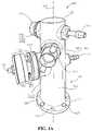
- FIG. 1 Ais a top perspective view of a fire hydrant comprising a nozzle cap assembly, in accordance with another aspect of the present disclosure, wherein the nozzle cap assembly comprises a nozzle cap and a nozzle cap adapter.
- FIG. 1 Bis a front view of the fire hydrant of FIG. 1 A with the nozzle cap assembly removed.
- FIG. 2is a rear perspective view of the nozzle cap of FIG. 1 A , in accordance with one aspect of the present disclosure.
- FIG. 3is a rear perspective view of the nozzle cap of FIG. 1 A coupled to the nozzle cap adapter of FIG. 1 .
- FIG. 4 Ais an exploded view of the nozzle cap adapter of FIG. 1 A .
- FIG. 4 Bis a perspective view of a first adapter segment of the nozzle cap adapter of FIG. 1 A .
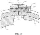
- FIG. 4 Cis a detail cross-sectional view of a first adapter segment of the nozzle cap adapter of FIG. 1 A coupled to a second adapter segment of the nozzle cap adapter of FIG. 1 A , taken along line 4 - 4 of FIG. 3 .
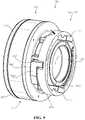
- FIG. 5is a rear perspective view of the nozzle cap coupled to the nozzle cap adapter, in accordance with another aspect of the present disclosure.
- FIG. 6is an exploded view of the nozzle cap adapter of FIG. 5 .
- FIG. 7is a rear perspective view of the nozzle cap coupled to the nozzle cap adapter, in accordance with another aspect of the present disclosure.
- FIG. 8is an exploded view of the nozzle cap adapter of FIG. 7 .
- FIG. 9is a rear perspective view of the nozzle cap coupled to the nozzle cap adapter, in accordance with another aspect of the present disclosure.
- FIG. 10is an exploded view of the nozzle cap adapter of FIG. 9 .
- Rangescan be expressed herein as from “about” one particular value, and/or to “about” another particular value. When such a range is expressed, another aspect includes from the one particular value and/or to the other particular value. Similarly, when values are expressed as approximations, by use of the antecedent “about,” it will be understood that the particular value forms another aspect. It will be further understood that the endpoints of each of the ranges are significant both in relation to the other endpoint, and independently of the other endpoint.
- a material property or dimension measuring about X or substantially X on a particular measurement scalemeasures within a range between X plus an industry-standard upper tolerance for the specified measurement and X minus an industry-standard lower tolerance for the specified measurement. Because tolerances can vary between different materials, processes and between different models, the tolerance for a particular measurement of a particular component can fall within a range of tolerances.
- the terms “optional” or “optionally”mean that the subsequently described event or circumstance can or cannot occur, and that the description includes instances where said event or circumstance occurs and instances where it does not.
- a nozzle cap adapterand associated methods, systems, devices, and various apparatus.
- Example aspects of the nozzle cap adaptercan be configured to mount a nozzle cap to a nozzle of a fire hydrant.
- the nozzle capcan comprise an adapter ring defining one or more nozzle connectors.
- the nozzle cap adaptercan be a U.S. Storz adapter configured to attach to a U.S. Storz nozzle. It would be understood by one of skill in the art that the disclosed nozzle cap adapter is described in but a few exemplary aspects among many. No particular terminology or description should be considered limiting on the disclosure or the scope of any claims issuing therefrom.
- FIG. 1 Ais a perspective view of a hydrant assembly 100 comprising a fire hydrant 110 and a nozzle cap assembly 130 , in accordance with one aspect of the present disclosure.
- the nozzle cap assembly 130can comprise a nozzle cap 150 and a nozzle cap adapter 160 .
- Example aspects of the fire hydrant 110can be a wet barrel hydrant, as shown; however, in other aspects, the fire hydrant 110 can be any other type of hydrant known in the art, such as, for example, a dry barrel hydrant.
- the fire hydrant 110can comprise a barrel 120 and one or more nozzles 140 (such as nozzles 140 a,b,c ).
- the nozzles 140 a,b,ccan comprise a U.S. Storz nozzles 142 a,b,c .
- the U.S. Storz nozzles 142can be non-threaded nozzles that can provide a quarter-turn connection.
- the nozzle cap adapter 160can be, for example, a U.S. Storz adapter 162 configured to mount the nozzle cap 150 to a U.S. Storz connector 141 of the U.S. Storz nozzle 142 a .
- the U.S. Storz connector 141is shown in further detail in FIG. 1 B .
- the barrel 120can be closed at a top barrel end 122 of the barrel 120 , as shown.
- other aspectsmay comprise a hydrant cap or bonnet (not shown) at the top barrel end 122 .
- a hydrant cap or bonnet(not shown) at the top barrel end 122 .
- watercan be present and fill the barrel 120 at all times, even when the fire hydrant 110 is not in use.
- Each of the nozzles 140 a,b,ccan house its own independent valve (not shown) to prevent or allow water flow to the respective nozzle 140 a,b,c .
- the barrel 120can be drained of water when the fire hydrant 110 is not in use, and a valve for preventing or allowing water flow to the nozzles 140 a,b,c can be housed below ground, such that water will not freeze in the barrel 120 in cold conditions.
- example aspects of the barrel 120can define the top barrel end 122 and a bottom barrel end 124 disposed opposite from the top barrel end 122 .
- Example aspects of the barrel 120can be substantially tubular and can define a barrel axis 101 extending from the top barrel end 122 to the bottom barrel end 124 . In the present aspect, the barrel axis 101 can be substantially vertically aligned.
- the barrel 120can comprise a base flange 128 disposed at the bottom barrel end 124 .
- the base flange 128can be fastened to a fluid system (not shown), such as a water main.
- the base flange 128can be fastened to a standpipe flange of a standpipe, for example and without limitation.
- the base flange 128 of the barrel 120can define a plurality of fastener openings 129 and can be fastened to the fluid system (e.g., to the standpipe flange) by one or more fasteners 127 , such as bolt and nut assemblies, engaged with the fastener openings 129 .
- the base flange 128can be fastened to the standpipe flange by any other suitable connection method known in the art, such as, for example and without limitation, threading, adhesives, welding, any suitable mechanical fasteners, or the like.
- example aspects of the barrel 120can comprise a first operation nut 184 a , or “op nut”, positioned opposite the nozzle 140 a and nozzle cap 150 , which can be rotated to open and close a first valve (not shown) mounted in the nozzle 140 a in order to respectively supply or cut off pressurized water flow through the nozzle 140 a from the barrel 120 .
- Example aspects of the barrel 120can further comprise a second operation nut 184 b positioned opposite the nozzle 140 b , which can be operated to open and close a second valve (not shown) mounted in the nozzle 140 b , and a third operation nut (not shown) positioned opposite the nozzle 140 c , which can be operated to open and close a third valve (not shown) mounted in the nozzle 140 c.
- the nozzle cap 150can be screwed onto the nozzle 140 a to seal the nozzle 140 a in a sealed orientation. With the nozzle cap 150 sealing the nozzle 140 a , pressurized water from the fluid system cannot escape through the nozzle 140 a . As shown, the nozzle cap 150 can define a cap nut 152 that can be turned, such as with a wrench or another suitable tool, to tighten or loosen the nozzle cap 150 on the nozzle 140 a . Furthermore, in some aspects, a hose cap 170 can be screwed onto the nozzle 140 b to seal the nozzle 140 b in a sealed orientation.
- the fire hydrant 110can be formed from a metal material, such as, for example, cast or ductile iron, and some or all of the nozzles 140 a,b,c can be formed from a metal material, such as cast or ductile iron. In other aspects, however, the fire hydrant 110 and/or the nozzles 140 a,b,c can be formed from any other suitable material or combination of materials known in the art.
- the nozzle cap 150can comprise a leak detection system (not shown).
- the nozzle cap 150may comprise a vibration sensor, which can be configured to detect leaks within the fluid system by monitoring vibrations travelling up the standpipe and through the fire hydrant 110 when the nozzle cap 150 is mounted on the nozzle 140 a . Vibration patterns within the fluid system can indicate the presence of leaks within the fluid system.
- the nozzle cap 150can further comprise an antenna (not shown), which can be configured to transmit a signal outwards from the nozzle cap 150 to convey whether leaks have been identified within the fluid system.
- FIG. 1 Billustrates the U.S. Storz connector 141 of the U.S. Storz nozzle 142 a with the nozzle cap assembly 130 (shown in FIG. 1 A ) removed.
- the U.S. Storz connector 141can generally comprise an outer ring 143 and an inner ring 144 connected to the outer ring 143 , and can define a substantially circular shape.
- the U.S. Storz connector 141can further define an opening 149 formed through a center thereof in some aspects, and the opening 149 can define a connector axis 103 (extending substantially into the page in the present view).
- a first arcuate slot 145 acan be defined between the outer and inner rings 143 , 144 .
- a second arcuate slot 145 bcan also be defined between the outer and inner rings 143 , 144 opposite the first arcuate slot 145 a .
- the first and second arcuate slots 145 a,bcan be substantially concentric to the connector axis 103 in some aspects, as shown.
- Each of the first and second arcuate slots 145 a,bcan define an insertion region 146 and a locking region 147 extending from the insertion region 146 , wherein the insertion region 146 can define a width greater than a width of the locking region 147 .
- Storz connector 141can further comprise a first connector arm 148 a and a second connector arm 148 b , wherein each of the first and second connector arms 148 a,b can extend substantially in the axial direction from a first end 105 of the U.S. Storz connector 141 .
- the first end 105 of the U.S. Storz connector 141can be distal to the fire hydrant 110 .
- the nozzle cap adapter 160shown in FIG. 1 A
- the U.S. Storz adapter 162shown in FIG. 1 A
- each of the nozzle connectors 310can be configured to engage one of the arcuate slots 145 a,b to couple the nozzle cap assembly 130 (shown in FIG. 1 A ) to the U.S. Storz nozzle 142 a , as described in further detail below.
- each of the of the first and second connector arms 148 a , 148 b of the U.S. Storz connector 141can be configured to engage a corresponding ramped surface 403 of the nozzle cap adapter 160 to tighten the nozzle cap assembly 130 with the U.S. Storz nozzle 142 a , as described in further detail below.
- FIG. 2is a rear perspective view of the nozzle cap 150 of FIG. 1 A .
- the nozzle cap 150can comprise a cap body 210 and a cap cover 280 .
- Example aspects of the cap cover 280can be formed from a metal material, such as for example, ductile iron, or can be formed from a plastic material, or any other suitable material known in the art.
- the cap body 210can comprise an outer housing 230 and an inner housing 340 (shown in FIG. 3 ).
- the outer housing 230can be substantially cylindrical in shape and can define a first outer housing end 232 and a second outer housing end 234 disposed opposite from the first outer housing end 232 .
- the cap cover 280can be mounted to the outer housing 230 at the first outer housing end 232
- the inner housing 340can be mounted to the outer housing 230 at the second outer housing end 234
- the outer housing 230can define a cap axis 201 extending generally through a center thereof, and the cap axis 201 can extend from the first outer housing end 232 to the second outer housing end 234 .
- the outer housing 230 and/or the inner housing 340can be formed from a substantially rigid material.
- the inner housing 340can be formed from a metal material, such as, for example, aluminum, and the outer housing 230 can be formed from a plastic material.
- Example aspects of the plastic material of the outer housing 230can be a glass-filled plastic material to provide an improved acoustic performance for the leak detection system.
- the leak detection systemcan be housed, or primarily housed, in the outer housing 230 .
- each of the inner housing 340 and outer housing 230can be formed from any other suitable material known in the art.
- the outer housing 230can define one or more mounting recesses 236 formed at the second outer housing end 234 thereof, wherein each of the mounting recesses 236 can be configured to receive a corresponding primary mounting leg 442 (shown in FIG. 4 A ) of the inner housing 340 .
- a mounting recess hole(not shown) can be formed through each mounting recess 236
- a corresponding cap cover hole(not shown) can be formed through the cap cover 280 and aligned with each of the mounting recess holes.
- a primary mounting leg hole 544(shown in FIG. 5 ) can be formed through each of the primary mounting legs 442 .
- a nozzle cap fastener(not shown), such as, for example and without limitation, a bolt or a screw, can be configured to extend through each corresponding cap cover hole, mounting recess hole, and primary mounting leg hole 544 to couple the cap cover 280 , inner housing 340 , and outer housing 230 together.
- three mounting recesses 236 and three primary mounting legs 442are present, but other aspects can comprise more or fewer mounting recesses 236 and primary mounting legs 442 .
- the nozzle cap 150can be a modular system wherein various components of the nozzle cap 150 , such as the outer housing 230 , can be easily removed and/or replaced, as desired.
- the nozzle cap 150can be similar to the modular nozzle cap disclosed in U.S. patent application Ser. No. 16/428,744, filed May 31, 2019, which is hereby specifically incorporated by reference herein in its entirety.
- FIG. 3illustrates a rear perspective view of the nozzle cap assembly 130 comprising the nozzle cap 150 and the nozzle cap adapter 160 .
- the inner housing 340 of the cap body 210is mounted to the outer housing 230 of the cap body 210 .
- the inner housing 340can comprise a housing body 342 , which can be substantially disc-shaped in the present aspect. Other aspects of the housing body 342 can define any other suitable shape.
- the housing body 342can generally define a first housing body end 344 and a second housing body end 345 , wherein the primary mounting legs 442 (shown in FIG. 4 A ) can extend from the first housing body end 344 .
- the first housing body end 344 of the housing body 342can be configured to abut the outer housing 230 at the second outer housing end 234 thereof.
- the nozzle cap adapter 160can be coupled to the inner housing 340 , wherein the nozzle cap adapter 160 can be configured to attach the nozzle cap 150 to the nozzle 140 a .
- the inner housing 340can define an annular outer flange 346 and an annular inner flange 348 , each of which can be substantially concentric to the cap axis 201 .
- annular outer flange 346 and annular inner flange 348can extend generally axially away from the second housing body end 345 of the housing body 342 , relative to the cap axis 201 .
- an annular gasket groove 460(shown in FIG. 4 A ) can be defined between the annular outer flange 346 and the annular inner flange 348 , and an annular gasket 350 can be received within the annular gasket groove 460 , as shown.
- the gasket 350can be configured to abut an end of the nozzle 140 a when the nozzle cap 150 is mounted thereto, in order to create a seal between the nozzle cap 150 and the nozzle 140 a.
- Example aspects of the nozzle cap adapter 160can comprise a first adapter segment 362 and a second adapter segment 364 .
- Each of the first and second adapter segments 362 , 364can be substantially semi-cylindrical in shape, such that the first and second adapter segments 362 , 364 can together define a substantially circular adapter ring 370 .
- the circular adapter ring 370can define an interior void 372 , as shown.
- the first adapter segment 362 and second adapter segment 364can be joined together by one or more adapter segment fasteners 365 , as described in further detail below with respect to FIG. 4 A .
- first and second adapter segments 362 , 364can be clamped around the outer flange 346 of the inner housing 340 to secure the adapter ring 370 thereto, as is also described in further detail below with respect to FIG. 4 A .
- Example aspects of the nozzle cap adapter 160can further comprise a latch 380 pivotally coupled to the first adapter segment 362 by a latch fastener 382 .
- the latch 380can be coupled to the second adapter segment 364 .
- the latch 380can be configured to engage the nozzle 140 a (shown in FIG.
- the latch 380can be spring-loaded.
- each of the first and second adapter segments 362 , 364can define a first adapter segment end 366 and a second adapter segment end 368 .
- the first adapter segment end 366 of each of the first and second adapter segments 362 , 364can be substantially aligned to generally define a first adapter ring end 376 of the adapter ring 370
- the second adapter segment end 368 of each of the first and second adapter segments 362 , 364can be substantially aligned to generally define a second adapter ring end 378 of the adapter ring 370 .
- each of the first and second adapter segments 362 , 364can comprise a one of the nozzle connectors 310 extending from the corresponding second adapter segment end 368 , away from the inner housing 340 .
- the nozzle connectors 310can be oriented on substantially opposite circumferential sides of the adapter ring 370 .
- each of the nozzle connectors 310can generally define an L-shape, wherein a leg 312 of the nozzle connector 310 is coupled at a proximal end 314 thereof to the second adapter ring end 378 and extends substantially axially therefrom, and an arm 318 of the nozzle connector 310 extends from a distal end 316 of the leg 312 and extends substantially radially outward therefrom.
- the arm 318 of the nozzle connector 310can be oriented about perpendicular to the leg 312 of the nozzle connector 310 .
- one or both of the first and second adapter segments 362 , 364can further define the ramped surface 403 extending from of the inner adapter segment surface 478 at or near the second adapter segment end 368 .
- a height of each of the ramped surfaces 403can increase along its length.
- each of the nozzle connectors 310can be configured to rotatably engage the U.S. Storz connector 141 (shown in FIG. 1 A- 1 B ) of the nozzle 140 a .
- each of the nozzle connectors 310can be inserted into the insertion region 146 (shown in FIG. 1 B ) of a corresponding one of the arcuate slots 145 a,b (shown in FIG. 1 B ) of the U.S. Storz connector 141 .
- the nozzle cap assembly 130can then be rotated in a first direction (e.g., clockwise) relative to the nozzle 140 a to rotate each of the nozzle connectors 310 into the locking region 147 of the corresponding arcuate slot 145 a,b .
- a first directione.g., clockwise
- the nozzle cap assembly 130can be rotated a quarter turn relative to the U.S. Storz nozzle 142 a to engage the U.S. Storz adapter 162 therewith and to secure the nozzle cap assembly 130 thereto.
- each locking region 147can be lesser than the width of the corresponding insertion region 146 .
- the arm 318 of each nozzle connectorcan engage the outer ring 143 of the U.S. Storz connector 141 to prohibit movement and/or removal of the nozzle cap assembly 130 in the axial direction.
- the latch 380can be configured to catch on one of the first and second connector arms 148 a,b to prohibit rotation movement and/or removal of the nozzle cap assembly 130 in a reverse direction (e.g., counter-clockwise), as described in further detail below with respect to FIG. 4 B .
- each of the connector arms 148 a,b of the U.S. Storz connector 141can be configured to engage a corresponding one of the ramped surfaces 403 as the nozzle cap assembly 130 is rotated.
- the height of each of the ramped surfaces 403can increase along its length. The rotation of the nozzle cap assembly 130 can move the connector arms 148 a,b in the direction of the increasing height of the ramped surfaces 403 , and as such, the ramped surfaces 403 can increasingly engage the connector arms 148 a,b to tighten the nozzle cap assembly 130 onto the U.S. Storz connector 141 .
- FIG. 4 Aillustrates an exploded view of the nozzle cap adapter 160 and the inner housing 340 .
- the inner housing 340can define the primary mounting legs 442 extending away from the first housing body end 344 of the housing body 342 in a substantially axial direction.
- the inner housing 340can further define the outer flange 346 and inner flange 348 extending away from the second housing body end 345 of the housing body 342 in a substantially axial direction, and the gasket groove 460 can be defined between the outer and inner flanges 346 , 348 .
- the annular gasket 350is provided and can be received within the gasket groove 460 when assembled with the inner housing 340 .
- one or more arcuate recesses 446formed about a circumference of the outer flange 346 at a proximal flange end 445 of the outer flange 346 , adjacent to the second housing body end 345 .
- the arcuate recesses 446can extend generally radially inward from an outer flange surface 448 of the outer flange 346 , as shown, and a non-recessed portion 452 of the outer flange 346 .
- example aspects of the outer flange 346can further define a semi-cylindrical recess 454 formed in the outer flange surface 448 thereof.
- the semi-cylindrical recess 454can extend substantially along a length of the outer flange 346 , from the proximal flange end 445 thereof to a distal flange end 447 thereof.
- Each of the first and second adapter segments 362 , 364can be substantially semicircular in shape and can define a first adapter segment circumferential end 466 and a second adapter segment circumferential end 468 .
- Each of the first and second adapter segments 362 , 364can further define an outer adapter segment surface 476 and an inner adapter segment surface 478 .
- the first adapter segment circumferential ends 466 of the corresponding first and second adapter segments 362 , 364can be joined together and the second adapter segment circumferential ends 468 of the corresponding first and second adapter segments 362 , 364 can be joined together to couple the first adapter segment 362 to the second adapter segment 364 .
- each of the first and second adapter segments 362 , 364can define a first fastener block 480 at the corresponding first adapter segment circumferential end 466 thereof.
- Each of the first and second adapter segments 362 , 364can further define a second fastener block 482 at the corresponding second adapter segment circumferential end 468 thereof.
- Each of the first and second fastener blocks 480 , 482can extend outward from the outer adapter segment surface 476 of the corresponding first and second adapter segments 362 , 364 .
- an adapter segment fastener hole 484can be formed through each of the first and second fastener blocks 480 , 482 .
- a first one of the adapter segment fasteners 365can engage the adapter segment fastener holes 484 of the pair of first fastener blocks 480 to couple the first adapter segment circumferential ends 466 to one another, and a second one of the adapter segment fasteners 365 can engage the adapter segment fastener holes 484 of the pair of second fastener blocks 482 to couple the second adapter segment circumferential ends 468 to one another.
- each of the adapter segment fasteners 365can define threading configured to engage mating threading formed in the corresponding adapter segment fastener holes 484 .
- first and second adapter segments 362 , 364can define one or more arcuate ribs 402 projecting generally radially inward from the corresponding inner adapter segment surface 478 and extending at least partially along a circumference of the inner adapter segment surface 478 adjacent to the first adapter segment end 366 .
- one or both of the first and second adapter segments 362 , 364can further define one or more substantially semi-cylindrical ribs 404 projecting generally radially inward from the corresponding inner adapter segment surface 478 and defining a substantially semi-circular cross section.
- the semi-cylindrical rib 404can define a rib fastener hole 406 therethrough, as shown, as will be described in further detail below.
- the semi-cylindrical rib 404can be formed adjacent to the first adapter segment end 366 and can be oriented between a pair of the arcuate ribs 402 .
- each of the first and second adapter segments 362 , 364can be clamped around the outer flange 346 of the inner housing 340 , and each of the arcuate ribs 402 can be configured to engage the arcuate recesses 446 formed in the outer flange 346 to prevent axial movement of the first and second adapter segments 362 , 364 relative to the inner housing 340 .
- axial movementcan be prevented by the interference of the non-recessed portion 452 of the outer flange 346 with the arcuate ribs 402 .
- the semi-cylindrical rib(s) 404can engage the corresponding semi-cylindrical recess(es) 454 formed in the outer flange 346 to prevent rotational movement of the first and/or second adapter segments 362 , 364 relative to the inner housing 340 .
- the adapter segment fasteners 365can then couple the first adapter segment 362 to the second adapter segment 364 to define the adapter ring 370 and to prevent removal of the adapter ring 370 from the inner housing 340 .
- the latch 380can be a substantially L-shaped latch 380 .
- the latch 380can define any other suitable shape.
- the latch 380can define a key fastener hole 490 extending therethrough.
- the latch 380can be configured to nest in a latch cutout 410 formed in the first adapter segment 362 .
- the latch cutout 410can be substantially L-shaped to generally match the L-shape of the latch 380 .
- example aspects of the latch cutout 410can be formed at the first adapter segment end 366 and can extend from the outer adapter segment surface 476 to the inner adapter segment surface 478 . In other aspects, the latch cutout 410 can be differently configured.
- first adapter segment 362 and second adapter segment 364can be substantially the same; for example, in some aspects, the first and second adapter segments 362 , 364 may be formed from the same mold or an identical mold for ease of manufacturing. As such, in the present aspect, the second adapter segment 364 can also define the latch cutout 410 , but the latch cutout 410 of the second adapter segment 364 can be superfluous. In other aspects, the first and second adapter segments 362 , 364 can differ in configuration.
- the inner housing 340can define an inner housing cutout 415 defined by a boundary 418 .
- the inner housing cutout 415can be aligned with the latch cutout 410 of the first adapter segment 362 and can be configured to receive at least a portion of the latch 380 .
- Example aspects of the inner housing cutout 415can extend radially inward from a peripheral edge 416 of the housing body 342 , and in the present aspect, can extend from the first housing body end 344 to the second housing body end 345 .
- the inner housing cutout 415can also extend radially inward from the outer flange surface 448 of the outer flange 346 and can span the length of the outer flange 346 from the proximal flange end 445 to the distal flange end 447 . As such, the inner housing cutout 415 can span a full length of the inner housing 340 , from the first housing body end 344 to the distal flange end 447 . In other aspects, the inner housing cutout 415 may not span the full length of the inner housing 340 and/or may not extend into the outer flange 346 .
- the key fastener hole 490 of the latch 380can be aligned with the rib fastener hole 406 of the semi-cylindrical rib 404 located on the first adapter segment 362 . (In the present view, only the semi-cylindrical rib 404 of the second adapter segment 364 is visible.) In this configuration, the latch 380 can be received within the latch cutout 410 of the first adapter segment 362 . To couple the latch 380 to the first adapter segment 362 , the latch fastener 382 can extend through each of the key fastener hole 490 and the rib fastener hole 406 .
- the latch fastener 382can define an un-threaded portion 492 configured to extend through the key fastener hole 490 and a threaded portion 494 configured to thread with mating threading (not shown) formed in the rib fastener hole 406 .
- the latch fastener 382can be inserted through the key fastener hole 490 , and then rotated to advance the engagement of the threaded portion 494 with the rib fastener hole 406 , tightening the latch fastener 382 into the first adapter segment 362 .
- the latch 380When the nozzle cap adapter 160 is assembled to the inner housing 340 , the latch 380 , or portions thereof, can be received within the inner housing cutout 415 , as illustrated in FIG. 3 .
- the latch 380can be configured to engage the nozzle 140 a (shown in FIG. 1 A ) when the nozzle cap assembly 130 (shown in FIG. 1 A ) is mounted thereto.
- the spring-loaded latch 380can be configured to slip over and catch on one of the connector arms 148 a,b of the nozzle 140 a to aid in securing the nozzle cap assembly 130 thereto.
- a usercan push the latch 380 in to disengage the latch 380 from the first or second connector arms 148 a,b , as described in further detail below, allowing for removal of the nozzle cap assembly 130 .
- FIG. 4 Billustrates the latch 380 in further detail.
- the latch 380can be received within the latch cutout 410 and can be pivotably mounted to the first adapter segment 362 by the latch fastener 382 .
- Example aspects of the latch 380can be spring-biased to an engaged configuration, as shown, but can be rotatable to a disengaged configuration upon application of a sufficient force, as described in additional detail below.
- the latch 380can define a latch leg 482 defining a first latch leg end 481 and a second latch leg end 483 .
- the latch 380can further define a latch arm 486 extending from the latch leg 482 proximate to the first latch leg end 481 and oriented substantially perpendicular to the latch leg 482 .
- the latch arm 486may define a sloped latch surface 487 , as shown.
- the spring-biased latch 380can be oriented such that the latch arm 486 can be rotated generally inward toward the cap axis 201 (shown in FIG. 3 ), while the second latch leg end 483 can rotated generally outward.
- a forcee.g., a manual force or a force supplied by a tool
- a forcecan be applied to the second latch leg end 483 of the latch leg 482 to rotate the second latch leg end 483 inward and to rotate the latch arm 486 outward.
- the nozzle connectors 310 of the nozzle cap adapter 160can engage the insertion region 146 (shown in FIG. 1 B ) of a corresponding one of the arcuate slots 145 a,b (shown in FIG. 1 B ) of the U.S. Storz connector 141 (shown in FIGS. 1 A- 1 B ), and the nozzle connectors 310 can be rotated in the first direction (e.g., clockwise) into the locking region 147 (shown in FIG. 1 B ) of the corresponding arcuate slot 145 a,b .
- the first directione.g., clockwise
- the latch 380can also be rotated towards a corresponding one of the connector arms 148 a or 148 b .
- the latch arm 486 of the spring-biased latch 380can be biased inward (i.e., the latch arm 486 can pivot inward about the latch fastener 382 towards the cap axis 201 ), such that the latch 380 can catch against the corresponding connector arm 148 a,b .
- the engagement of the latch arm 486 with the corresponding connector arm 148 a,bcan prohibit the nozzle cap adapter 160 from being rotated in the reverse direction (e.g., counter-clockwise), and thus, can prohibit removal of the nozzle cap assembly 130 (shown in FIG. 1 A ) from the fire hydrant 110 (shown in FIG. 1 A ).
- the latch arm 486can be pivoted outward, such that the latch 380 can clear the corresponding connector arm 148 a,b , and the nozzle cap assembly 130 can be rotated in the reverse direction for removal from the fire hydrant 110 .
- FIG. 4 Cillustrates a cross-sectional detail view of the first adapter segment circumferential ends 466 of the first and second adapter segments 362 , 364 joined together by the corresponding adapter segment fastener 365 .
- the adapter segment fastener 365can define a fastener head 367 and a fastener tail 369 extending from the fastener head 367 .
- the fastener tail 369can define fastener threading 371 in some aspects.
- the fastener tail 369can be inserted through the adapter segment fastener hole 484 of the first fastener block 480 of the first adapter segment 362 , which can be an unthreaded hole in some aspects.
- the adapter segment fastener 365can then thread into the adapter segment fastener hole 484 of the second adapter segment 364 , which can be a threaded hole in the present aspect, to secure the first adapter segment 362 to the second adapter segment 364 at the first adapter segment circumferential ends 466 thereof.
- the second adapter segment circumferential ends 468can be secured together in substantially the same manner.
- FIG. 5illustrates the nozzle cap assembly 130 comprising the nozzle cap 150 and the nozzle cap adapter 160 , in accordance with another aspect of the present disclosure.
- the nozzle cap 150can comprise the cap cover 280 and the cap body 210
- the cap body 210can comprise the outer housing 230 and the inner housing 340 .
- the nozzle cap adapter 160can be coupled to the inner housing 340 of the nozzle cap 150 to allow the nozzle cap 150 to be mounted to the nozzle 140 a (shown in FIG. 1 A ) of the fire hydrant 110 (shown in FIG. 1 A ).
- the nozzle cap adapter 160can again be the U.S.
- Storz adapter 162which can be configured to mount the nozzle cap 150 to the U.S. Storz nozzle 142 a (shown in FIG. 1 A ).
- the nozzle cap adapter 160can comprise the adapter ring 370 , latch 380 , and gasket 350 , as shown.
- the inner housing 340may not comprise the outer and inner flanges 346 , 348 .
- the nozzle cap adapter 160can comprise a gasket housing 560
- the gasket housing 560can comprise the outer and inner flanges 346 , 348 .
- the outer and inner flanges 346 , 348 of the gasket housing 560can define the gasket groove 460 (shown in FIG.
- the gasket housing 560can be coupled to one or both of the inner housing 340 and adapter ring 370 , as described in further detail below with respect to FIG. 6 .
- the inner housing 340also may not comprise the inner housing cutout 415 (shown in FIG. 4 A ).
- FIG. 6illustrates an exploded view of the inner housing 340 of FIG. 5 and the nozzle cap adapter 160 of FIG. 5 .
- the inner housing 340comprises the housing body 342 defining the first housing body end 344 and second housing body end 345 .
- the primary mounting legs 442can extend from the first housing body end 344 for mounting the inner housing 340 to the outer housing 230 (shown in FIG. 2 ).
- the inner housing 340can further comprising a clearance hole 642
- the adapter ring 370can define a first adapter ring key hole 672 .
- the clearance hole 642 and the first adapter ring key hole 672can be substantially aligned, as described in further detail below.
- the inner housing 340can define one or more secondary mounting legs 644 extending from the second housing body end 345 generally in the axial direction.
- the secondary mounting legs 644can be oriented radially inward from the primary mounting legs 442 in some aspects.
- each of the secondary mounting legs 644can define a secondary mounting leg hole 646 configured to receive a gasket housing fastener (not shown) therethrough.
- the gasket housing fastenermay be a screw or a bolt in some aspects.
- the gasket housing fastener(s)can be configured to engage the gasket housing 560 , as described in further detail below, to couple the gasket housing 560 to the inner housing 340 .
- the adapter ring 370can be monolithically formed and may not comprise the first and second adapter segments 362 , 364 (shown in FIG. 3 ).
- the adapter ring 370 of the present aspectcan be configured differently from the adapter ring 370 shown in the aspect of FIGS. 3 - 4 C .
- the present adapter ring 370can define the first adapter ring end 376 and the second adapter ring end 378 .
- the adapter ring 370can further generally define an outer adapter ring surface 676 and an inner adapter ring surface 678 .
- one or more adapter ring reinforcement ribs 680can extend from and be spaced about a circumference of the outer adapter ring surface 676 .
- an annular adapter ring flange 682can extend generally radially inward from the inner adapter ring surface 678 , and can define a flange upper surface 684 and a flange lower surface (not shown).
- the nozzle connectors 310can extend from the second adapter ring end 378 and can be oriented on substantially opposite sides of the adapter ring 370 .
- the nozzle connectors 310 of the present aspectcan define the L-shape, comprising the leg 312 and arm 318 as described above, and can be configured to engage the nozzle 140 a (shown in FIG. 1 A ) to secure the nozzle cap assembly 130 (shown in FIG. 1 A ) to the nozzle 140 a.
- the adapter ring 370can define a latch alcove 686 formed therein for receiving the latch 380 , similar to the latch cutout 410 (shown in FIG. 4 A ) described above.
- the latch 380can be substantially similar to the latch 380 described above with respect to FIGS. 3 - 4 A.
- the latch 380can be substantially L-shaped and can define the key fastener hole 490 extending therethrough.
- the latch alcove 686can be partially bound by a latch shelf 688 extending from the outer adapter ring surface 676 , proximate to the first adapter ring end 376 thereof.
- the latch shelf 688can define the first adapter ring key hole 672 formed therethrough.
- the adapter ring 370can define a second adapter ring key hole (not shown) formed therein, wherein the second adapter ring key hole can be aligned with the first adapter ring key hole 672 and oriented at an opposing side of the latch alcove 686 .
- the latch fastener 382(shown in FIG. 3 ) can extend through the first adapter ring key hole 672 and key fastener hole 490 , and into the second adapter ring key hole, to couple the latch 380 to the adapter ring 370 .
- a portion of the latch fastener 382may extend into the clearance hole 642 .
- the latch fastener 382may not extend into the clearance hole 642 .
- Example aspects of the gasket housing 560can define a first gasket housing end 662 and a second gasket housing end 664 .
- the outer and inner flanges 346 , 348can be formed at the second gasket housing end 664 , as shown.
- an annular gasket housing shoulder 666can extend generally radially outward from an outer gasket housing surface 668 at a location between the first gasket housing end 662 and the outer and inner flanges 346 , 348 .
- the gasket housing 560may not be directly coupled to the adapter ring 370 . However, in other aspects, the gasket housing 560 may be directly coupled to the adapter ring 370 .
- mechanical fastenerse.g., screws, nuts and bolts, etc.
- the gasket housing 560may define external threading configured to thread into internal threading the adapter ring 370 (or vice versa) to couple the gasket housing 560 to the adapter ring 370 .
- the first adapter ring end 376 of the adapter ring 370can be positioned to abut the second housing body end 345 of the housing body 342 .
- the gasket housing 560can then be inserted into the interior void 372 of the adapter ring 370 .
- the annular gasket housing shoulder 666can engage the flange upper surface 684 of the annular adapter ring flange 682 to retain the adapter ring 370 between the gasket housing 560 and the inner housing 340 .
- Each of the secondary mounting legs 644can extend into the interior void 372 of the adapter ring 370 , and the secondary mounting leg hole 646 of each secondary mounting leg 644 can be aligned with a gasket housing hole (not shown) formed at the first gasket housing end 662 .
- the gasket housing fastener(not shown) can be configured to extend through each of secondary mounting leg 644 holes 646 and into a corresponding one of the gasket housing holes to couple the gasket housing 560 , and thus couple the nozzle cap adapter 160 , to the inner housing 340 .
- FIG. 7illustrates the nozzle cap assembly 130 comprising the nozzle cap 150 and the nozzle cap adapter 160 , in accordance with another aspect of the present disclosure.
- the nozzle cap 150can comprise the cap cover 280 and the cap body 210
- the cap body 210can comprise the outer housing 230 and the inner housing 340 .
- the nozzle cap adapter 160such as the U.S. Storz adapter 162
- the nozzle cap adapter 160can be coupled to the inner housing 340 of the nozzle cap 150 to allow the nozzle cap 150 to be mounted to the nozzle 140 a , such as the U.S. Storz nozzle 142 a (both 140 a and 142 a shown in FIG. 1 A ), of the fire hydrant 110 (shown in FIG.
- the nozzle cap adapter 160 of the present aspectcan be similar to the nozzle cap adapter 160 of FIGS. 5 - 6 .
- the nozzle cap adapter 160can comprise the adapter ring 370 and the gasket housing 560 .
- the latch 380can be received in the latch cutout 410 of the adapter ring 370
- the gasket 350can be received in the gasket groove 460 (shown in FIG. 8 ) of the gasket housing 560 .
- the inner housing 340 and portions of the adapter ring 370can be configured differently from the aspect of FIGS. 5 - 6 , as shown and described in further detail below with respect to FIG. 8 .
- FIG. 8illustrates an exploded an exploded view of the inner housing 340 of FIG. 7 and the nozzle cap adapter 160 of FIG. 7 .
- the nozzle cap adapter 160can be similar to the nozzle cap adapter 160 of FIGS. 5 - 6 , as described above.
- the adapter ring 370can comprise the latch cutout 410 instead of the latch alcove 686 (shown in FIG. 6 ).
- the inner housing 340can define the housing body 342
- the housing body 342can define the first housing body end 344 and the second housing body end 345 .
- the primary mounting legs 442can extend from the first housing body end 344 for engaging the mounting recesses 236 (shown in FIG.
- a housing body opening 844can be formed substantially through a center of the housing body 342 , such that the housing body opening 844 is substantially concentric to the cap axis 201 , and can extend from the first housing body end 344 to the second housing body end 345 .
- a first locking ring 810can be provided for coupling the adapter ring 370 to the inner housing 340 . As shown, the first locking ring 810 can abut an inner housing shoulder 848 formed at a boundary 846 of the housing body opening 844 , preventing the first locking ring 810 from advancing through the housing body opening 844 in a direction towards the second housing body end 345 .
- the first adapter ring end 376can pass through the housing body opening 844 , and the first locking ring 810 can be configured to engage an annular adapter ring slot 872 formed in the outer adapter ring surface 676 to couple the adapter ring 370 to the inner housing 340 .
- a second locking ring 815can be provided for coupling the gasket housing 560 to the adapter ring 370 .
- the second locking ring 815can abut the flange lower surface of the annular adapter ring flange 682 to prevent the second locking ring 815 from advancing through the interior void 372 of the adapter ring 370 in a direction towards the nozzle connectors 310 .
- the gasket housing 560can be inserted into the interior void 372 through the second adapter ring end 378 , and the second locking ring 815 can be configured to engage an annular gasket housing slot 862 formed in the outer gasket housing surface 668 of the gasket housing 560 to couple the gasket housing 560 to the adapter ring 370 .
- FIG. 9illustrates the nozzle cap assembly 130 comprising the nozzle cap 150 and the nozzle cap adapter 160 , in accordance with another aspect of the present disclosure.
- the nozzle cap 150can comprise the cap cover 280 and the cap body 210
- the cap body 210can comprise the outer housing 230 and the inner housing 340 .
- the nozzle cap adapter 160can be coupled to the inner housing 340 of the nozzle cap 150 to allow the nozzle cap 150 to be mounted to the nozzle 140 a (shown in FIG. 1 A ).
- the nozzle cap adapter 160 of the present aspectcan be similar to the nozzle cap adapters 160 of FIGS. 5 - 6 and FIGS. 7 - 8 .
- the nozzle cap adapter 160can comprise the adapter ring 370 and the gasket housing 560 .
- the latch 380can be received in the latch cutout 410 of the adapter ring 370
- the gasket 350can be received in the gasket groove 460 (shown in FIG. 10 ) of the gasket housing 560 .
- the inner housing 340 and portions of the adapter ring 370can be configured differently from the aspect of FIGS. 5 - 6 , as shown and described in further detail below with respect to FIG. 10 .
- FIG. 10illustrates the inner housing 340 of FIG. 9 and the nozzle cap adapter 160 of FIG. 9 .
- the gasket housing 560can be substantially the same as the gasket housing 560 of FIGS. 7 - 9 , and the second locking ring 815 can couple the gasket housing 560 to the adapter ring 370 in the same manner.
- the present aspectdoes not comprise the first locking ring 810 (shown in FIG. 8 ).
- the inner housing 340can define internal threading 1042 formed at the boundary 846 of the housing body opening 844 .
- the adapter ring 370can define external threading 1072 formed on the outer adapter ring surface 676 proximate to the first adapter ring end 376 .
- the external threading 1072 of the adapter ring 370can thread into the internal threading 1042 of the inner housing 340 to couple the nozzle cap adapter 160 to the inner housing 340 .
- the inner housing 340can define a housing body shoulder 1044 extending radially inward from the boundary 846 of the housing body opening 844 at the first housing body end 344 thereof.
- the housing body shoulder 1044can serve as a stop by engaging the first adapter ring end 376 of the adapter ring 370 when the adapter ring 370 is appropriately tightened onto the inner housing 340 .
- conditional languagesuch as, among others, “can,” “could,” “might,” or “may,” unless specifically stated otherwise, or otherwise understood within the context as used, is generally intended to convey that certain embodiments include, while other embodiments do not include, certain features, elements and/or steps. Thus, such conditional language is not generally intended to imply that features, elements and/or steps are in any way required for one or more particular embodiments or that one or more particular embodiments necessarily include logic for deciding, with or without user input or prompting, whether these features, elements and/or steps are included or are to be performed in any particular embodiment.
Landscapes
- Engineering & Computer Science (AREA)
- General Engineering & Computer Science (AREA)
- Mechanical Engineering (AREA)
- Health & Medical Sciences (AREA)
- Life Sciences & Earth Sciences (AREA)
- Hydrology & Water Resources (AREA)
- Public Health (AREA)
- Water Supply & Treatment (AREA)
- Quick-Acting Or Multi-Walled Pipe Joints (AREA)
- Fire-Extinguishing By Fire Departments, And Fire-Extinguishing Equipment And Control Thereof (AREA)
- Nozzles (AREA)
Abstract
Description
This disclosure relates to fire hydrants. More specifically, this disclosure relates to a nozzle cap adapter for mounting a nozzle cap to a hydrant nozzle.
Fire hydrants are commonly connected to fluid systems, such as municipal water infrastructure systems and water mains, through standpipes. Nozzle caps can be connected to nozzles of the fire hydrant to seal the nozzles when they are not in use and/or to mount various systems (e.g., a leak detection system) to the nozzles. Fire hydrants can define varying styles of nozzle connections (e.g., threaded nozzle connection, U.S. Storz nozzle connection, Canadian Storz nozzle connection, etc.) to which the nozzle cap can be connected. Nozzle caps configured to connect to a particular style of nozzle connection may be unable to connect to nozzle connections of another style.
It is to be understood that this summary is not an extensive overview of the disclosure. This summary is exemplary and not restrictive, and it is intended neither to identify key or critical elements of the disclosure nor delineate the scope thereof. The sole purpose of this summary is to explain and exemplify certain concepts of the disclosure as an introduction to the following complete and extensive detailed description.
Disclosed is a nozzle cap adapter comprising an adapter ring defining a first adapter ring end, a second adapter ring end opposite the first adapter ring end, and an interior void extending from the first adapter ring end to the second adapter ring end; a nozzle connector extending from the second end of the adapter ring, the nozzle connector configured to rotatably engage a fire hydrant nozzle; and a latch coupled to the adapter ring and configured to removably lock the nozzle cap adapter onto the fire hydrant nozzle.
Also disclosed is a nozzle cap assembly comprising a nozzle cap comprising an outer housing and an inner housing; and a nozzle cap adapter coupled to the inner housing, the nozzle cap adapter comprising: an adapter ring; and a nozzle connector extending from the adapter ring, the nozzle connector configured to engage a fire hydrant nozzle.
A method for mounting a nozzle cap to a fire hydrant nozzle is also disclosed, the method comprising providing a nozzle cap assembly, the nozzle cap assembly comprising a nozzle cap and a nozzle cap adapter, the nozzle cap adapter coupled to an inner housing of the nozzle cap, the nozzle cap adapter comprising an adapter ring and a nozzle connector extending from the adapter ring; engaging the nozzle connector with a fire hydrant nozzle; and rotating the nozzle cap assembly relative to the fire hydrant nozzle to secure the nozzle cap assembly to the fire hydrant nozzle.
Various implementations described in the present disclosure may include additional systems, methods, features, and advantages, which may not necessarily be expressly disclosed herein but will be apparent to one of ordinary skill in the art upon examination of the following detailed description and accompanying drawings. It is intended that all such systems, methods, features, and advantages be included within the present disclosure and protected by the accompanying claims.
The features and components of the following figures are illustrated to emphasize the general principles of the present disclosure. Corresponding features and components throughout the figures may be designated by matching reference characters for the sake of consistency and clarity.
The present disclosure can be understood more readily by reference to the following detailed description, examples, drawings, and claims, and the previous and following description. However, before the present devices, systems, and/or methods are disclosed and described, it is to be understood that this disclosure is not limited to the specific devices, systems, and/or methods disclosed unless otherwise specified, and, as such, can, of course, vary. It is also to be understood that the terminology used herein is for the purpose of describing particular aspects only and is not intended to be limiting.
The following description is provided as an enabling teaching of the present devices, systems, and/or methods in its best, currently known aspect. To this end, those skilled in the relevant art will recognize and appreciate that many changes can be made to the various aspects of the present devices, systems, and/or methods described herein, while still obtaining the beneficial results of the present disclosure. It will also be apparent that some of the desired benefits of the present disclosure can be obtained by selecting some of the features of the present disclosure without utilizing other features. Accordingly, those who work in the art will recognize that many modifications and adaptations to the present disclosure are possible and can even be desirable in certain circumstances and are a part of the present disclosure. Thus, the following description is provided as illustrative of the principles of the present disclosure and not in limitation thereof.
As used throughout, the singular forms “a,” “an” and “the” include plural referents unless the context clearly dictates otherwise. Thus, for example, reference to “an element” can include two or more such elements unless the context indicates otherwise.
Ranges can be expressed herein as from “about” one particular value, and/or to “about” another particular value. When such a range is expressed, another aspect includes from the one particular value and/or to the other particular value. Similarly, when values are expressed as approximations, by use of the antecedent “about,” it will be understood that the particular value forms another aspect. It will be further understood that the endpoints of each of the ranges are significant both in relation to the other endpoint, and independently of the other endpoint.
For purposes of the current disclosure, a material property or dimension measuring about X or substantially X on a particular measurement scale measures within a range between X plus an industry-standard upper tolerance for the specified measurement and X minus an industry-standard lower tolerance for the specified measurement. Because tolerances can vary between different materials, processes and between different models, the tolerance for a particular measurement of a particular component can fall within a range of tolerances.
As used herein, the terms “optional” or “optionally” mean that the subsequently described event or circumstance can or cannot occur, and that the description includes instances where said event or circumstance occurs and instances where it does not.
The word “or” as used herein means any one member of a particular list and also includes any combination of members of that list. Further, one should note that conditional language, such as, among others, “can,” “could,” “might,” or “may,” unless specifically stated otherwise, or otherwise understood within the context as used, is generally intended to convey that certain aspects include, while other aspects do not include, certain features, elements and/or steps. Thus, such conditional language is not generally intended to imply that features, elements and/or steps are in any way required for one or more particular aspects or that one or more particular aspects necessarily include logic for deciding, with or without user input or prompting, whether these features, elements and/or steps are included or are to be performed in any particular aspect.
Disclosed are components that can be used to perform the disclosed methods and systems. These and other components are disclosed herein, and it is understood that when combinations, subsets, interactions, groups, etc. of these components are disclosed that while specific reference of each various individual and collective combinations and permutations of these may not be explicitly disclosed, each is specifically contemplated and described herein, for all methods and systems. This applies to all aspects of this application including, but not limited to, steps in disclosed methods. Thus, if there are a variety of additional steps that can be performed it is understood that each of these additional steps can be performed with any specific aspect or combination of aspects of the disclosed methods.
Disclosed in the present application is a nozzle cap adapter and associated methods, systems, devices, and various apparatus. Example aspects of the nozzle cap adapter can be configured to mount a nozzle cap to a nozzle of a fire hydrant. The nozzle cap can comprise an adapter ring defining one or more nozzle connectors. In some aspects, the nozzle cap adapter can be a U.S. Storz adapter configured to attach to a U.S. Storz nozzle. It would be understood by one of skill in the art that the disclosed nozzle cap adapter is described in but a few exemplary aspects among many. No particular terminology or description should be considered limiting on the disclosure or the scope of any claims issuing therefrom.
According to example aspects, thebarrel 120 can comprise abase flange 128 disposed at thebottom barrel end 124. Thebase flange 128 can be fastened to a fluid system (not shown), such as a water main. In one aspect, thebase flange 128 can be fastened to a standpipe flange of a standpipe, for example and without limitation. Thebase flange 128 of thebarrel 120 can define a plurality offastener openings 129 and can be fastened to the fluid system (e.g., to the standpipe flange) by one ormore fasteners 127, such as bolt and nut assemblies, engaged with thefastener openings 129. In other aspects, thebase flange 128 can be fastened to the standpipe flange by any other suitable connection method known in the art, such as, for example and without limitation, threading, adhesives, welding, any suitable mechanical fasteners, or the like. As shown, example aspects of thebarrel 120 can comprise afirst operation nut 184a, or “op nut”, positioned opposite thenozzle 140aandnozzle cap 150, which can be rotated to open and close a first valve (not shown) mounted in thenozzle 140ain order to respectively supply or cut off pressurized water flow through thenozzle 140afrom thebarrel 120. Example aspects of thebarrel 120 can further comprise asecond operation nut 184bpositioned opposite thenozzle 140b, which can be operated to open and close a second valve (not shown) mounted in thenozzle 140b, and a third operation nut (not shown) positioned opposite thenozzle 140c, which can be operated to open and close a third valve (not shown) mounted in thenozzle 140c.
According to example aspects, thenozzle cap 150 can be screwed onto thenozzle 140ato seal thenozzle 140ain a sealed orientation. With thenozzle cap 150 sealing thenozzle 140a, pressurized water from the fluid system cannot escape through thenozzle 140a. As shown, thenozzle cap 150 can define acap nut 152 that can be turned, such as with a wrench or another suitable tool, to tighten or loosen thenozzle cap 150 on thenozzle 140a. Furthermore, in some aspects, ahose cap 170 can be screwed onto thenozzle 140bto seal thenozzle 140bin a sealed orientation. Some aspects, such as the present aspect, can further comprise aquick connect adapter 175 attached to thenozzle 140cfor to facilitate the attachment of a fire hose (not shown) to thenozzle 140c. According to example aspects, thefire hydrant 110 can be formed from a metal material, such as, for example, cast or ductile iron, and some or all of thenozzles 140a,b,ccan be formed from a metal material, such as cast or ductile iron. In other aspects, however, thefire hydrant 110 and/or thenozzles 140a,b,ccan be formed from any other suitable material or combination of materials known in the art.
In example aspects, thenozzle cap 150 can comprise a leak detection system (not shown). For example, thenozzle cap 150 may comprise a vibration sensor, which can be configured to detect leaks within the fluid system by monitoring vibrations travelling up the standpipe and through thefire hydrant 110 when thenozzle cap 150 is mounted on thenozzle 140a. Vibration patterns within the fluid system can indicate the presence of leaks within the fluid system. According to example aspects, thenozzle cap 150 can further comprise an antenna (not shown), which can be configured to transmit a signal outwards from thenozzle cap 150 to convey whether leaks have been identified within the fluid system.
According to example aspects, theouter housing 230 and/or theinner housing 340 can be formed from a substantially rigid material. For example, theinner housing 340 can be formed from a metal material, such as, for example, aluminum, and theouter housing 230 can be formed from a plastic material. Example aspects of the plastic material of theouter housing 230 can be a glass-filled plastic material to provide an improved acoustic performance for the leak detection system. In example aspects, the leak detection system can be housed, or primarily housed, in theouter housing 230. In other aspects, each of theinner housing 340 andouter housing 230 can be formed from any other suitable material known in the art.
As shown, in the present aspect, theouter housing 230 can define one or more mounting recesses236 formed at the secondouter housing end 234 thereof, wherein each of the mountingrecesses 236 can be configured to receive a corresponding primary mounting leg442 (shown inFIG.4A ) of theinner housing 340. In some example aspects, a mounting recess hole (not shown) can be formed through each mountingrecess 236, and a corresponding cap cover hole (not shown) can be formed through thecap cover 280 and aligned with each of the mounting recess holes. Furthermore, a primary mounting leg hole544 (shown inFIG.5 ) can be formed through each of the primary mountinglegs 442. A nozzle cap fastener (not shown), such as, for example and without limitation, a bolt or a screw, can be configured to extend through each corresponding cap cover hole, mounting recess hole, and primary mountingleg hole 544 to couple thecap cover 280,inner housing 340, andouter housing 230 together. In the present aspect, three mountingrecesses 236 and three primary mountinglegs 442 are present, but other aspects can comprise more or fewer mounting recesses236 and primary mountinglegs 442. Furthermore, according to example aspects, thenozzle cap 150 can be a modular system wherein various components of thenozzle cap 150, such as theouter housing 230, can be easily removed and/or replaced, as desired. For example, it may be desired to remove theouter housing 230 temporarily for repair or to replace the removedouter housing 230 with a newouter housing 230 or a different cap body module. For example, thenozzle cap 150 can be similar to the modular nozzle cap disclosed in U.S. patent application Ser. No. 16/428,744, filed May 31, 2019, which is hereby specifically incorporated by reference herein in its entirety.
Example aspects of thenozzle cap adapter 160 can comprise afirst adapter segment 362 and asecond adapter segment 364. Each of the first andsecond adapter segments second adapter segments circular adapter ring 370. Thecircular adapter ring 370 can define aninterior void 372, as shown. Thefirst adapter segment 362 andsecond adapter segment 364 can be joined together by one or moreadapter segment fasteners 365, as described in further detail below with respect toFIG.4A . In example aspects, the first andsecond adapter segments outer flange 346 of theinner housing 340 to secure theadapter ring 370 thereto, as is also described in further detail below with respect toFIG.4A . Example aspects of thenozzle cap adapter 160 can further comprise alatch 380 pivotally coupled to thefirst adapter segment 362 by alatch fastener 382. In other aspects, thelatch 380 can be coupled to thesecond adapter segment 364. Thelatch 380 can be configured to engage thenozzle 140a(shown inFIG.1A ) to lock thenozzle cap assembly 130 onto thenozzle 140, preventing unintentional removable of thenozzle cap assembly 130 from the fire hydrant110 (shown inFIG.1A ), as is described in further detail below with respect toFIG.4A . In some example aspects, thelatch 380 can be spring-loaded.
According to example aspects, as shown, each of the first andsecond adapter segments adapter segment end 366 and a secondadapter segment end 368. The firstadapter segment end 366 of each of the first andsecond adapter segments adapter ring end 376 of theadapter ring 370, and the secondadapter segment end 368 of each of the first andsecond adapter segments adapter ring end 378 of theadapter ring 370. As shown, each of the first andsecond adapter segments nozzle connectors 310 extending from the corresponding secondadapter segment end 368, away from theinner housing 340. In the present aspect, thenozzle connectors 310 can be oriented on substantially opposite circumferential sides of theadapter ring 370. In some aspects, as shown, each of thenozzle connectors 310 can generally define an L-shape, wherein aleg 312 of thenozzle connector 310 is coupled at aproximal end 314 thereof to the secondadapter ring end 378 and extends substantially axially therefrom, and anarm 318 of thenozzle connector 310 extends from adistal end 316 of theleg 312 and extends substantially radially outward therefrom. As such, thearm 318 of thenozzle connector 310 can be oriented about perpendicular to theleg 312 of thenozzle connector 310. According to example aspects, one or both of the first andsecond adapter segments surface 403 extending from of the inneradapter segment surface 478 at or near the secondadapter segment end 368. In example aspects, a height of each of the rampedsurfaces 403 can increase along its length.
In example aspects, each of thenozzle connectors 310 can be configured to rotatably engage the U.S. Storz connector141 (shown inFIG.1A-1B ) of thenozzle 140a. For example, in some aspects, each of thenozzle connectors 310 can be inserted into the insertion region146 (shown inFIG.1B ) of a corresponding one of thearcuate slots 145a,b(shown inFIG.1B ) of theU.S. Storz connector 141. Thenozzle cap assembly 130 can then be rotated in a first direction (e.g., clockwise) relative to thenozzle 140ato rotate each of thenozzle connectors 310 into the lockingregion 147 of the correspondingarcuate slot 145a,b. For example, in aspects wherein thenozzle cap adapter 160 is theU.S. Storz adapter 162, and thenozzle 140ais theU.S. Storz nozzle 142a, thenozzle cap assembly 130 can be rotated a quarter turn relative to theU.S. Storz nozzle 142ato engage theU.S. Storz adapter 162 therewith and to secure thenozzle cap assembly 130 thereto. As described above, the width of each lockingregion 147 can be lesser than the width of thecorresponding insertion region 146. As such, when thenozzle connectors 310 are rotated into the corresponding lockingregions 147, thearm 318 of each nozzle connector can engage theouter ring 143 of theU.S. Storz connector 141 to prohibit movement and/or removal of thenozzle cap assembly 130 in the axial direction. According to example aspects, thelatch 380 can be configured to catch on one of the first andsecond connector arms 148a,bto prohibit rotation movement and/or removal of thenozzle cap assembly 130 in a reverse direction (e.g., counter-clockwise), as described in further detail below with respect toFIG.4B . Moreover, each of theconnector arms 148a,bof theU.S. Storz connector 141 can be configured to engage a corresponding one of the rampedsurfaces 403 as thenozzle cap assembly 130 is rotated. In example aspects, as described above, the height of each of the rampedsurfaces 403 can increase along its length. The rotation of thenozzle cap assembly 130 can move theconnector arms 148a,bin the direction of the increasing height of the rampedsurfaces 403, and as such, the rampedsurfaces 403 can increasingly engage theconnector arms 148a,bto tighten thenozzle cap assembly 130 onto theU.S. Storz connector 141.
Each of the first andsecond adapter segments circumferential end 466 and a second adapter segmentcircumferential end 468. Each of the first andsecond adapter segments adapter segment surface 476 and an inneradapter segment surface 478. In the assembled configuration, the first adapter segment circumferential ends466 of the corresponding first andsecond adapter segments second adapter segments first adapter segment 362 to thesecond adapter segment 364. Coupling the first andsecond adapter segments FIG.3 ). In the present aspect, each of the first andsecond adapter segments first fastener block 480 at the corresponding first adapter segmentcircumferential end 466 thereof. Each of the first andsecond adapter segments second fastener block 482 at the corresponding second adapter segmentcircumferential end 468 thereof. Each of the first and second fastener blocks480,482 can extend outward from the outeradapter segment surface 476 of the corresponding first andsecond adapter segments segment fastener hole 484 can be formed through each of the first and second fastener blocks480,482. A first one of theadapter segment fasteners 365 can engage the adapter segment fastener holes484 of the pair of first fastener blocks480 to couple the first adapter segment circumferential ends466 to one another, and a second one of theadapter segment fasteners 365 can engage the adapter segment fastener holes484 of the pair of second fastener blocks482 to couple the second adapter segment circumferential ends468 to one another. In example aspects, each of theadapter segment fasteners 365 can define threading configured to engage mating threading formed in the corresponding adapter segment fastener holes484. The coupling of thefirst adapter segment 362 to thesecond adapter segment 364 by theadapter segment fasteners 365 is shown and described in further detail below with respect toFIG.4C .
One or both of the first andsecond adapter segments arcuate ribs 402 projecting generally radially inward from the corresponding inneradapter segment surface 478 and extending at least partially along a circumference of the inneradapter segment surface 478 adjacent to the firstadapter segment end 366. In some aspects, one or both of the first andsecond adapter segments semi-cylindrical ribs 404 projecting generally radially inward from the corresponding inneradapter segment surface 478 and defining a substantially semi-circular cross section. In some aspects, thesemi-cylindrical rib 404 can define arib fastener hole 406 therethrough, as shown, as will be described in further detail below. Referring to thesecond adapter segment 364, in the present aspect, thesemi-cylindrical rib 404 can be formed adjacent to the firstadapter segment end 366 and can be oriented between a pair of thearcuate ribs 402.
To secure the first andsecond adapter segments inner housing 340, each of the first andsecond adapter segments outer flange 346 of theinner housing 340, and each of thearcuate ribs 402 can be configured to engage thearcuate recesses 446 formed in theouter flange 346 to prevent axial movement of the first andsecond adapter segments inner housing 340. For example, axial movement can be prevented by the interference of thenon-recessed portion 452 of theouter flange 346 with thearcuate ribs 402. Furthermore, the semi-cylindrical rib(s)404 can engage the corresponding semi-cylindrical recess(es)454 formed in theouter flange 346 to prevent rotational movement of the first and/orsecond adapter segments inner housing 340. Theadapter segment fasteners 365 can then couple thefirst adapter segment 362 to thesecond adapter segment 364 to define theadapter ring 370 and to prevent removal of theadapter ring 370 from theinner housing 340.
As shown, thelatch 380 can be a substantially L-shapedlatch 380. In other aspects, thelatch 380 can define any other suitable shape. Thelatch 380 can define akey fastener hole 490 extending therethrough. According to example aspects, thelatch 380 can be configured to nest in alatch cutout 410 formed in thefirst adapter segment 362. In the present aspect, thelatch cutout 410 can be substantially L-shaped to generally match the L-shape of thelatch 380. Furthermore, example aspects of thelatch cutout 410 can be formed at the firstadapter segment end 366 and can extend from the outeradapter segment surface 476 to the inneradapter segment surface 478. In other aspects, thelatch cutout 410 can be differently configured. In the present aspect, thefirst adapter segment 362 andsecond adapter segment 364 can be substantially the same; for example, in some aspects, the first andsecond adapter segments second adapter segment 364 can also define thelatch cutout 410, but thelatch cutout 410 of thesecond adapter segment 364 can be superfluous. In other aspects, the first andsecond adapter segments
Theinner housing 340 can define aninner housing cutout 415 defined by aboundary 418. In example aspects, theinner housing cutout 415 can be aligned with thelatch cutout 410 of thefirst adapter segment 362 and can be configured to receive at least a portion of thelatch 380. Example aspects of theinner housing cutout 415 can extend radially inward from aperipheral edge 416 of thehousing body 342, and in the present aspect, can extend from the firsthousing body end 344 to the secondhousing body end 345. In some aspects, as shown, theinner housing cutout 415 can also extend radially inward from theouter flange surface 448 of theouter flange 346 and can span the length of theouter flange 346 from theproximal flange end 445 to thedistal flange end 447. As such, theinner housing cutout 415 can span a full length of theinner housing 340, from the firsthousing body end 344 to thedistal flange end 447. In other aspects, theinner housing cutout 415 may not span the full length of theinner housing 340 and/or may not extend into theouter flange 346.
According to example aspects, thekey fastener hole 490 of thelatch 380 can be aligned with therib fastener hole 406 of thesemi-cylindrical rib 404 located on thefirst adapter segment 362. (In the present view, only thesemi-cylindrical rib 404 of thesecond adapter segment 364 is visible.) In this configuration, thelatch 380 can be received within thelatch cutout 410 of thefirst adapter segment 362. To couple thelatch 380 to thefirst adapter segment 362, thelatch fastener 382 can extend through each of thekey fastener hole 490 and therib fastener hole 406. In the present aspect, as shown, thelatch fastener 382 can define anun-threaded portion 492 configured to extend through thekey fastener hole 490 and a threadedportion 494 configured to thread with mating threading (not shown) formed in therib fastener hole 406. As such, thelatch fastener 382 can be inserted through thekey fastener hole 490, and then rotated to advance the engagement of the threadedportion 494 with therib fastener hole 406, tightening thelatch fastener 382 into thefirst adapter segment 362.
When thenozzle cap adapter 160 is assembled to theinner housing 340, thelatch 380, or portions thereof, can be received within theinner housing cutout 415, as illustrated inFIG.3 . In example aspects, thelatch 380 can be configured to engage thenozzle 140a(shown inFIG.1A ) when the nozzle cap assembly130 (shown inFIG.1A ) is mounted thereto. For example, in a particular aspect, the spring-loadedlatch 380 can be configured to slip over and catch on one of theconnector arms 148a,bof thenozzle 140ato aid in securing thenozzle cap assembly 130 thereto. To remove thenozzle cap assembly 130 from thenozzle 140a, a user can push thelatch 380 in to disengage thelatch 380 from the first orsecond connector arms 148a,b, as described in further detail below, allowing for removal of thenozzle cap assembly 130.
In example aspects, as described above, thenozzle connectors 310 of the nozzle cap adapter160 (shown inFIG.1A ) can engage the insertion region146 (shown inFIG.1B ) of a corresponding one of thearcuate slots 145a,b(shown inFIG.1B ) of the U.S. Storz connector141 (shown inFIGS.1A-1B ), and thenozzle connectors 310 can be rotated in the first direction (e.g., clockwise) into the locking region147 (shown inFIG.1B ) of the correspondingarcuate slot 145a,b. As thenozzle cap adapter 160 is rotated, thelatch 380 can also be rotated towards a corresponding one of theconnector arms latch 380 passes the correspondingconnector arm 148a,b, thelatch arm 486 of the spring-biasedlatch 380 can be biased inward (i.e., thelatch arm 486 can pivot inward about thelatch fastener 382 towards the cap axis201), such that thelatch 380 can catch against the correspondingconnector arm 148a,b. The engagement of thelatch arm 486 with the correspondingconnector arm 148a,bcan prohibit thenozzle cap adapter 160 from being rotated in the reverse direction (e.g., counter-clockwise), and thus, can prohibit removal of the nozzle cap assembly130 (shown inFIG.1A ) from the fire hydrant110 (shown inFIG.1A ). However, when a suitable force is applied to the secondlatch leg end 483 of thelatch leg 482, thelatch arm 486 can be pivoted outward, such that thelatch 380 can clear thecorresponding connector arm 148a,b, and thenozzle cap assembly 130 can be rotated in the reverse direction for removal from thefire hydrant 110.
In some example aspects, as shown, theadapter ring 370 can be monolithically formed and may not comprise the first andsecond adapter segments 362,364 (shown inFIG.3 ). Theadapter ring 370 of the present aspect can be configured differently from theadapter ring 370 shown in the aspect ofFIGS.3-4C . However, similar to the aspect ofFIGS.3-4C , thepresent adapter ring 370 can define the firstadapter ring end 376 and the secondadapter ring end 378. Theadapter ring 370 can further generally define an outeradapter ring surface 676 and an inneradapter ring surface 678. In the present aspect, one or more adapterring reinforcement ribs 680 can extend from and be spaced about a circumference of the outeradapter ring surface 676. Furthermore, as shown, an annularadapter ring flange 682 can extend generally radially inward from the inneradapter ring surface 678, and can define a flangeupper surface 684 and a flange lower surface (not shown). Thenozzle connectors 310 can extend from the secondadapter ring end 378 and can be oriented on substantially opposite sides of theadapter ring 370. Thenozzle connectors 310 of the present aspect can define the L-shape, comprising theleg 312 andarm 318 as described above, and can be configured to engage thenozzle 140a(shown inFIG.1A ) to secure the nozzle cap assembly130 (shown inFIG.1A ) to thenozzle 140a.
Moreover, theadapter ring 370 can define alatch alcove 686 formed therein for receiving thelatch 380, similar to the latch cutout410 (shown inFIG.4A ) described above. As shown, thelatch 380 can be substantially similar to thelatch 380 described above with respect to FIGS.3-4A. For example, thelatch 380 can be substantially L-shaped and can define thekey fastener hole 490 extending therethrough. In the present aspect, thelatch alcove 686 can be partially bound by alatch shelf 688 extending from the outeradapter ring surface 676, proximate to the firstadapter ring end 376 thereof. Thelatch shelf 688 can define the first adapter ringkey hole 672 formed therethrough. In some aspects, theadapter ring 370 can define a second adapter ring key hole (not shown) formed therein, wherein the second adapter ring key hole can be aligned with the first adapter ringkey hole 672 and oriented at an opposing side of thelatch alcove 686. As such, in example aspects, the latch fastener382 (shown inFIG.3 ) can extend through the first adapter ringkey hole 672 andkey fastener hole 490, and into the second adapter ring key hole, to couple thelatch 380 to theadapter ring 370. In some aspects, when thenozzle cap adapter 160 is mounted to theinner housing 340, a portion of thelatch fastener 382 may extend into theclearance hole 642. However, in other aspects, thelatch fastener 382 may not extend into theclearance hole 642.
Example aspects of thegasket housing 560 can define a firstgasket housing end 662 and a secondgasket housing end 664. The outer andinner flanges gasket housing end 664, as shown. Furthermore, an annulargasket housing shoulder 666 can extend generally radially outward from an outergasket housing surface 668 at a location between the firstgasket housing end 662 and the outer andinner flanges gasket housing 560 may not be directly coupled to theadapter ring 370. However, in other aspects, thegasket housing 560 may be directly coupled to theadapter ring 370. For example, in one aspect, mechanical fasteners (e.g., screws, nuts and bolts, etc.) may be provided for coupling thegasket housing 560 to theadapter ring 370. In another example aspect, thegasket housing 560 may define external threading configured to thread into internal threading the adapter ring370 (or vice versa) to couple thegasket housing 560 to theadapter ring 370. To mount thenozzle cap adapter 160 to theinner housing 340, the firstadapter ring end 376 of theadapter ring 370 can be positioned to abut the second housing body end345 of thehousing body 342. Thegasket housing 560 can then be inserted into theinterior void 372 of theadapter ring 370. The annulargasket housing shoulder 666 can engage the flangeupper surface 684 of the annularadapter ring flange 682 to retain theadapter ring 370 between thegasket housing 560 and theinner housing 340. Each of the secondary mountinglegs 644 can extend into theinterior void 372 of theadapter ring 370, and the secondary mountingleg hole 646 of each secondary mountingleg 644 can be aligned with a gasket housing hole (not shown) formed at the firstgasket housing end 662. The gasket housing fastener (not shown) can be configured to extend through each of secondary mountingleg 644holes 646 and into a corresponding one of the gasket housing holes to couple thegasket housing 560, and thus couple thenozzle cap adapter 160, to theinner housing 340.
One should note that conditional language, such as, among others, “can,” “could,” “might,” or “may,” unless specifically stated otherwise, or otherwise understood within the context as used, is generally intended to convey that certain embodiments include, while other embodiments do not include, certain features, elements and/or steps. Thus, such conditional language is not generally intended to imply that features, elements and/or steps are in any way required for one or more particular embodiments or that one or more particular embodiments necessarily include logic for deciding, with or without user input or prompting, whether these features, elements and/or steps are included or are to be performed in any particular embodiment.
It should be emphasized that the above-described embodiments are merely possible examples of implementations, merely set forth for a clear understanding of the principles of the present disclosure. Any process descriptions or blocks in flow diagrams should be understood as representing modules, segments, or portions of code which include one or more executable instructions for implementing specific logical functions or steps in the process, and alternate implementations are included in which functions may not be included or executed at all, may be executed out of order from that shown or discussed, including substantially concurrently or in reverse order, depending on the functionality involved, as would be understood by those reasonably skilled in the art of the present disclosure. Many variations and modifications may be made to the above-described embodiment(s) without departing substantially from the spirit and principles of the present disclosure. Further, the scope of the present disclosure is intended to cover any and all combinations and sub-combinations of all elements, features, and aspects discussed above. All such modifications and variations are intended to be included herein within the scope of the present disclosure, and all possible claims to individual aspects or combinations of elements or steps are intended to be supported by the present disclosure.
Claims (16)
1. A nozzle cap adapter comprising:
an adapter ring defining a first adapter ring end, a second adapter ring end opposite the first adapter ring end, and an interior void extending from the first adapter ring end to the second adapter ring end;
a nozzle connector extending from the second adapter ring end of the adapter ring, the nozzle connector configured to rotatably engage a fire hydrant nozzle; and
a latch coupled to the adapter ring and configured to removably lock the nozzle cap adapter onto the fire hydrant nozzle;
wherein the adapter ring defines an arcuate rib extending radially inward from an inner adapter segment surface of the adapter ring at the first adapter ring end, the arcuate rib configured to engage an arcuate recess of a nozzle cap.
2. The nozzle cap adapter ofclaim 1 , wherein:
the nozzle connector defines a leg and an arm;
a proximal end of the leg is coupled to the adapter ring; and
the arm extends from a distal end of the leg.
3. The nozzle cap adapter ofclaim 2 , wherein the arm extends radially outward from the leg and is oriented about perpendicular to the leg.
4. The nozzle cap adapter ofclaim 1 , wherein the adapter ring defines one of a latch cutout and a latch alcove, and the latch is received within the one of the latch cutout and latch alcove.
5. The nozzle cap adapter ofclaim 1 , wherein:
the adapter ring comprises a first adapter segment and a second adapter segment; and
the first adapter segment is coupled to the second adapter segment by a first adapter segment fastener.
6. The nozzle cap adapter ofclaim 5 , wherein:
each of the first and second adapter segments define a first adapter segment circumferential end and a second adapter segment circumferential end;
a first fastener block is formed at each of the first adapter segment circumferential ends;
a second fastener block is formed at each of the second adapter segment circumferential ends;
the first adapter segment fastener engages each of the first fastener blocks to couple the first adapter segment circumferential ends together; and
a second adapter segment fastener engages each of the second fastener blocks to couple the second adapter segment circumferential ends together.
7. The nozzle cap adapter ofclaim 1 , wherein the adapter ring defines a semi-cylindrical rib extending radially inward from an inner adapter segment surface of the adapter ring from the first adapter ring end to the second adapter ring end, the semi-cylindrical rib configured to engage a semi-cylindrical recess of a nozzle cap.
8. The nozzle cap adapter ofclaim 1 , further comprising:
a gasket housing defining a first gasket housing end, a second gasket housing end, and a gasket groove; and
a gasket received within the gasket groove, the gasket configured to engage the fire hydrant nozzle.
9. The nozzle cap adapter ofclaim 8 , wherein:
the gasket housing defines an outer flange at the second gasket housing end and an inner flange at the second gasket housing end; and
the gasket groove is defined between the inner flange and the outer flange.
10. A nozzle cap assembly comprising:
a nozzle cap comprising an outer housing and an inner housing; and
a nozzle cap adapter coupled to the inner housing, the nozzle cap adapter comprising:
an adapter ring; and
a nozzle connector extending from the adapter ring, the nozzle connector configured to engage a fire hydrant nozzle;
wherein the inner housing defines a housing body, an outer flange, and an inner flange, the outer flange and inner flange define a gasket groove therebetween, and a gasket is received within the gasket groove; and
wherein the adapter ring comprises an arcuate rib, the outer flange defines an arcuate recess, and the arcuate rib engages the arcuate recess.
11. The nozzle cap assembly ofclaim 10 , further comprising a latch coupled to the adapter ring and configured to removably lock the nozzle cap assembly onto the fire hydrant nozzle.
12. The nozzle cap assembly ofclaim 10 , wherein:
the adapter ring comprises a first adapter segment and a second adapter segment; and
the first adapter segment and second adapter segment are clamped around the outer flange to couple the nozzle cap adapter to the inner housing.
13. The nozzle cap assembly ofclaim 10 , the nozzle cap adapter further comprising a gasket housing received in an interior void of the adapter ring, the gasket housing defining a gasket groove and a gasket received within the gasket groove.
14. The nozzle cap assembly ofclaim 10 , wherein the adapter ring comprises a plurality of adapter ring reinforcement ribs spaced about a circumference of an outer adapter ring surface of the adapter ring.
15. A nozzle cap adapter comprising:
an adapter ring defining a first adapter ring end, a second adapter ring end opposite the first adapter ring end, and an interior void extending from the first adapter ring end to the second adapter ring end;
a nozzle connector extending from the second adapter ring end of the adapter ring, the nozzle connector configured to rotatably engage a fire hydrant nozzle; and
a latch coupled to the adapter ring and configured to removably lock the nozzle cap adapter onto the fire hydrant nozzle;
wherein:
the adapter ring comprises a first adapter segment and a second adapter segment; and
the first adapter segment is coupled to the second adapter segment by a first adapter segment fastener;
each of the first and second adapter segments define a first adapter segment circumferential end and a second adapter segment circumferential end;
a first fastener block is formed at each of the first adapter segment circumferential ends;
a second fastener block is formed at each of the second adapter segment circumferential ends;
the first adapter segment fastener engages each of the first fastener blocks to couple the first adapter segment circumferential ends together; and
a second adapter segment fastener engages each of the second fastener blocks to couple the second adapter segment circumferential ends together.
16. A nozzle cap adapter comprising:
an adapter ring defining a first adapter ring end, a second adapter ring end opposite the first adapter ring end, and an interior void extending from the first adapter ring end to the second adapter ring end;
a nozzle connector extending from the second adapter ring end of the adapter ring, the nozzle connector configured to rotatably engage a fire hydrant nozzle; and
a latch coupled to the adapter ring and configured to removably lock the nozzle cap adapter onto the fire hydrant nozzle;
wherein the adapter ring defines a semi-cylindrical rib extending radially inward from an inner adapter segment surface of the adapter ring from the first adapter ring end to the second adapter ring end, the semi-cylindrical rib configured to engage a semi-cylindrical recess of a nozzle cap.
Priority Applications (5)
| Application Number | Priority Date | Filing Date | Title |
|---|---|---|---|
| US16/874,340US11542690B2 (en) | 2020-05-14 | 2020-05-14 | Hydrant nozzle cap adapter |
| CA3178637ACA3178637A1 (en) | 2020-05-14 | 2021-05-06 | Hydrant nozzle cap adapter |
| PCT/US2021/031033WO2021231163A1 (en) | 2020-05-14 | 2021-05-06 | Hydrant nozzle cap adapter |
| US18/071,359US12084844B2 (en) | 2020-05-14 | 2022-11-29 | Hydrant nozzle cap adapter |
| US18/790,252US20240392543A1 (en) | 2020-05-14 | 2024-07-31 | Hydrant nozzle cap adapter |
Applications Claiming Priority (1)
| Application Number | Priority Date | Filing Date | Title |
|---|---|---|---|
| US16/874,340US11542690B2 (en) | 2020-05-14 | 2020-05-14 | Hydrant nozzle cap adapter |
Related Child Applications (1)
| Application Number | Title | Priority Date | Filing Date |
|---|---|---|---|
| US18/071,359ContinuationUS12084844B2 (en) | 2020-05-14 | 2022-11-29 | Hydrant nozzle cap adapter |
Publications (2)
| Publication Number | Publication Date |
|---|---|
| US20210355661A1 US20210355661A1 (en) | 2021-11-18 |
| US11542690B2true US11542690B2 (en) | 2023-01-03 |
Family
ID=78512311
Family Applications (3)
| Application Number | Title | Priority Date | Filing Date |
|---|---|---|---|
| US16/874,340Active2041-01-08US11542690B2 (en) | 2020-05-14 | 2020-05-14 | Hydrant nozzle cap adapter |
| US18/071,359ActiveUS12084844B2 (en) | 2020-05-14 | 2022-11-29 | Hydrant nozzle cap adapter |
| US18/790,252PendingUS20240392543A1 (en) | 2020-05-14 | 2024-07-31 | Hydrant nozzle cap adapter |
Family Applications After (2)
| Application Number | Title | Priority Date | Filing Date |
|---|---|---|---|
| US18/071,359ActiveUS12084844B2 (en) | 2020-05-14 | 2022-11-29 | Hydrant nozzle cap adapter |
| US18/790,252PendingUS20240392543A1 (en) | 2020-05-14 | 2024-07-31 | Hydrant nozzle cap adapter |
Country Status (3)
| Country | Link |
|---|---|
| US (3) | US11542690B2 (en) |
| CA (1) | CA3178637A1 (en) |
| WO (1) | WO2021231163A1 (en) |
Cited By (10)
| Publication number | Priority date | Publication date | Assignee | Title |
|---|---|---|---|---|
| US20220041194A1 (en)* | 2018-01-24 | 2022-02-10 | Amsted Rail Company, Inc. | Sensing method, system and assembly for railway assets |
| US20220135093A1 (en)* | 2018-01-24 | 2022-05-05 | Amsted Rail Company, Inc. | Discharge Gate Sensing Method, System and Assembly |
| US11624674B2 (en) | 2019-05-31 | 2023-04-11 | Mueller International, Llc | Hydrant nozzle cap with antenna |
| US11630021B2 (en) | 2011-08-12 | 2023-04-18 | Mueller International, Llc | Enclosure for leak detector |
| US11652284B2 (en) | 2016-02-12 | 2023-05-16 | Mueller International, Llc | Nozzle cap assembly |
| US11692901B2 (en) | 2018-09-04 | 2023-07-04 | Mueller International, Llc | Hydrant cap leak detector with oriented sensor |
| USD1024281S1 (en)* | 2020-10-14 | 2024-04-23 | Mcwane, Inc. | Hydrant monitoring cap |
| US12084844B2 (en) | 2020-05-14 | 2024-09-10 | Mueller International, Llc | Hydrant nozzle cap adapter |
| US12212053B2 (en) | 2016-02-12 | 2025-01-28 | Mueller International, Llc | Nozzle cap multi-band antenna assembly |
| US12370995B2 (en) | 2018-07-12 | 2025-07-29 | Amsted Rail Company, Inc. | Brake monitoring systems for railcars |
Families Citing this family (3)
| Publication number | Priority date | Publication date | Assignee | Title |
|---|---|---|---|---|
| US8931505B2 (en) | 2010-06-16 | 2015-01-13 | Gregory E. HYLAND | Infrastructure monitoring devices, systems, and methods |
| US11342656B2 (en) | 2018-12-28 | 2022-05-24 | Mueller International, Llc | Nozzle cap encapsulated antenna system |
| US11613877B2 (en) | 2020-10-01 | 2023-03-28 | AMI Investments, LLC | Monitoring apparatus for hydrant |
Citations (348)
| Publication number | Priority date | Publication date | Assignee | Title |
|---|---|---|---|---|
| US1738094A (en) | 1928-12-03 | 1929-12-03 | Caldwell | Sound-locating apparatus |
| US2171173A (en) | 1936-12-11 | 1939-08-29 | Frederick C Coyer | Sound pick-up unit |
| US3254528A (en) | 1962-11-23 | 1966-06-07 | Paul L Michael | Transducer mount |
| US3592967A (en) | 1968-05-20 | 1971-07-13 | George A Harris | Ultrasonic detector |
| US3612922A (en) | 1970-11-10 | 1971-10-12 | Gen Motors Corp | Method of mounting a piezoelectric device |
| US3662600A (en) | 1969-11-05 | 1972-05-16 | Gamon Calmet Ind Inc | Fluid meter |
| US3673856A (en) | 1970-01-20 | 1972-07-04 | Pier L Panigati | Fluid operated sensor |
| US3731534A (en) | 1970-11-18 | 1973-05-08 | Rockwell Mfg Co | Housing structure for meters |
| US3815129A (en) | 1970-08-20 | 1974-06-04 | Mallory & Co Inc P R | Piezoelectric transducer and noise making device utilizing same |
| US4000753A (en) | 1975-07-29 | 1977-01-04 | Mueller Co. | Means for locking replaceable nozzles to fire hydrants |
| US4056970A (en) | 1975-10-30 | 1977-11-08 | Yeda Research And Development Co., Ltd. | Ultrasonic velocity and thickness gage |
| US4083229A (en) | 1976-09-28 | 1978-04-11 | Plaunt & Anderson Company, Inc. | Method and apparatus for detecting and locating fluid leaks |
| US4156156A (en) | 1977-08-18 | 1979-05-22 | P. R. Mallory & Co. Inc. | Method for reducing the resonant frequency of a piezoelectric transducer |
| FR2439990A1 (en) | 1978-10-25 | 1980-05-23 | Gaz De France | Detecting leakage from gas pipeline - requires hollow cylindrical element to isolate section while allowing continuing gas flow |
| JPS5654124A (en) | 1979-10-11 | 1981-05-14 | Hitachi Ltd | Contact read-in circuit |
| US4333028A (en) | 1980-04-21 | 1982-06-01 | Milltronics Ltd. | Damped acoustic transducers with piezoelectric drivers |
| JPS595856B2 (en) | 1975-03-14 | 1984-02-07 | 株式会社日立製作所 | Fouct Kouka Omochiita Bunko Bunseki Kei |
| US4431873A (en) | 1981-01-09 | 1984-02-14 | Her Majesty The Queen In Right Of Canada, As Represented By The Minister Of National Defence | Diaphragm design for a bender type acoustic sensor |
| US4462249A (en) | 1981-03-13 | 1984-07-31 | Adams Thomas E | Tank leakage detection method |
| US4467236A (en) | 1981-01-05 | 1984-08-21 | Piezo Electric Products, Inc. | Piezoelectric acousto-electric generator |
| JPS59170739A (en) | 1983-03-16 | 1984-09-27 | Tokiko Yuki Kk | Leak inspecting method of tank |
| JPS60111132A (en) | 1983-11-18 | 1985-06-17 | Tokiko Yuki Kk | Leakage inspecting method of tank |
| US4543817A (en) | 1982-03-31 | 1985-10-01 | Hitachi, Ltd. | Method of detecting a leakage of fluid |
| US4763686A (en) | 1988-01-22 | 1988-08-16 | Halliburton Company | Hydrant and components thereof |
| US4796466A (en) | 1987-02-17 | 1989-01-10 | Ed Farmer | System for monitoring pipelines |
| US4844396A (en) | 1987-02-20 | 1989-07-04 | Badger Meter, Inc. | Strap on pipe mounting |
| US4893679A (en) | 1988-03-01 | 1990-01-16 | Grinnell Corporation | Heat-responsive element for fire protection sprinklers or the like |
| US4930358A (en) | 1987-03-27 | 1990-06-05 | Tokyo Keiki Co., Ltd. | Method of and apparatus for measuring flow velocity by using ultrasonic waves |
| US4984498A (en) | 1987-10-26 | 1991-01-15 | Lawrence Fishman | Percussion transducer |
| US5038614A (en) | 1989-08-10 | 1991-08-13 | Atlantic Richfield Company | Acoustic vibration detection of fluid leakage from conduits |
| US5052215A (en) | 1990-10-18 | 1991-10-01 | Lewis Donald E | Leak detection in storage tank bottoms by pneumatic enhancement of acoustic emissions |
| US5078006A (en) | 1990-08-30 | 1992-01-07 | Vista Research, Inc. | Methods for detection of leaks in pressurized pipeline systems |
| US5085082A (en) | 1990-10-24 | 1992-02-04 | The Babcock & Wilcox Company | Apparatus and method of discriminating flaw depths in the inspection of tubular products |
| US5090234A (en) | 1990-08-30 | 1992-02-25 | Vista Research, Inc. | Positive displacement pump apparatus and methods for detection of leaks in pressurized pipeline systems |
| US5117676A (en) | 1991-02-25 | 1992-06-02 | Hughes Aircraft Company | Leak detector for natural gas pipelines |
| US5118464A (en) | 1991-03-15 | 1992-06-02 | General Electric Company | Method of ultrasonic inspection of materials through opaque barriers |
| GB2250820A (en) | 1990-12-12 | 1992-06-17 | Christopher David Hill | Method of and apparatus for detecting leaks in liquid storage tanks acoustically |
| US5163314A (en) | 1990-08-30 | 1992-11-17 | Vista Research, Inc. | Temperature compensated methods for detection of leaks in pressurized pipeline systems using gas controlled apparatus |
| US5165280A (en) | 1990-08-28 | 1992-11-24 | Nukem Gmbh | Device for testing of oblong objects by means of ultrasonic waves |
| US5170657A (en) | 1990-08-30 | 1992-12-15 | Vista Research, Inc. | Temperature compensated methods for detection of leaks in pressurized pipeline systems |
| US5174155A (en) | 1990-03-07 | 1992-12-29 | Mitsubishi Denki Kabushiki Kaisha | Ultrasonic pipe inspection system |
| US5184851A (en)* | 1991-09-25 | 1993-02-09 | Fred Sparling | Coupling with auxiliary latch and release mechanism |
| US5187973A (en) | 1989-05-19 | 1993-02-23 | Silvia Kunze | Leak monitor for hydraulic drive systems |
| US5189904A (en) | 1990-08-30 | 1993-03-02 | Vista Research, Inc. | Temperature compensated methods for detection of leaks in pressurized pipeline systems using piston displacement apparatus |
| US5201226A (en) | 1990-07-20 | 1993-04-13 | Westinghouse Electric Corp. | Ultrasonic tube inspection station for a rapid changeover multi-diameter tube inspection system |
| US5203202A (en) | 1992-02-25 | 1993-04-20 | W. L. Gore & Associates, Inc. | Apparatus for detecting leaks in circuits |
| US5205173A (en) | 1991-06-21 | 1993-04-27 | Palmer Environmental Services | Method and apparatus for detecting leaks in pipelines using cross-correlation techniques |
| US5209125A (en) | 1989-12-22 | 1993-05-11 | The Foxboro Company | Piezoelectric pressure sensor |
| US5218859A (en) | 1989-02-15 | 1993-06-15 | Danfoss A/S | Method and apparatus for monitoring a conduit system for an incompressible fluid for leaks |
| US5243862A (en) | 1991-06-04 | 1993-09-14 | The Babcock & Wilcox Company | Confirmation of hydrogen damage in boiler tubes by refracted shear waves |
| DE4211038A1 (en) | 1992-04-02 | 1993-10-07 | Karl Rekers Maschinenbau Fa Di | Leak testing system for pipes - has generator for producing pressure difference between inside and outside of pipe and microphones for detecting noises typical of leaks inside pipe and correction microphones outside. |
| US5254944A (en) | 1992-04-16 | 1993-10-19 | Westinghouse Electric Corp. | Inspection probe for inspecting irregularly-shaped tubular members for anomalies |
| US5272646A (en) | 1991-04-11 | 1993-12-21 | Farmer Edward J | Method for locating leaks in a fluid pipeline and apparatus therefore |
| US5279160A (en) | 1990-08-07 | 1994-01-18 | Nukem Gmbh | Array for non-destructive material testing of cylindrical workpieces by means of electrodynamic ultrasonic measurement |
| US5287884A (en) | 1992-07-24 | 1994-02-22 | Cohen Jeffrey D | Water flow monitoring system for determining the presence of leaks and stopping flow in plumbing pipes |
| GB2269900A (en) | 1992-08-19 | 1994-02-23 | Christopher David Hill | Acoustic leak detection method for liquid storage tanks |
| US5298894A (en) | 1992-06-17 | 1994-03-29 | Badger Meter, Inc. | Utility meter transponder/antenna assembly for underground installations |
| US5301985A (en) | 1993-03-05 | 1994-04-12 | Angus Fire Armour Corp. | Double point supported locking lever for a hose coupling assembly |
| US5303592A (en) | 1991-12-05 | 1994-04-19 | Livingston Waylon A | Method and apparatus for coiled tubing inspection |
| US5319956A (en) | 1991-10-07 | 1994-06-14 | Tanknology Corporation International | Method of confirming the presence of a leak in a liquid storage tank |
| US5333501A (en) | 1989-09-19 | 1994-08-02 | Tokyo Gas Co., Ltd. | Abnormality monitoring apparatus for a pipeline |
| US5335547A (en) | 1989-08-21 | 1994-08-09 | Hitachi Construction Machinery Co., Ltd. | Ultrasonic flaw detector |
| US5343737A (en) | 1992-09-22 | 1994-09-06 | Joseph Baumoel | Method and apparatus for leak detection and pipeline temperature modelling method and apparatus |
| US5349568A (en) | 1993-09-27 | 1994-09-20 | The University Of Chicago | Leak locating microphone, method and system for locating fluid leaks in pipes |
| US5351655A (en) | 1994-01-18 | 1994-10-04 | The Babcock & Wilcox Company | Acoustic emission signal collector manifold |
| US5361636A (en) | 1992-09-23 | 1994-11-08 | Columbia Gas Of Ohio, Inc. | Apparatus and process for measuring the magnitude of leaks |
| US5367911A (en) | 1991-03-21 | 1994-11-29 | Halliburton Logging Services, Inc. | Device for sensing fluid behavior |
| US5385049A (en) | 1990-11-22 | 1995-01-31 | Hunt; Hugh E. M. | Pipeline pig and method of pipeline inspection |
| US5396800A (en) | 1993-03-17 | 1995-03-14 | Westinghouse Electric Corporation | Apparatus and method for inspecting a control rod drive mechanism penetration tube for degradation |
| US5408883A (en) | 1992-06-09 | 1995-04-25 | Westinghouse Electric Corporation | Remotely operated diagnostic tube sampling device and method of sampling |
| US5416724A (en) | 1992-10-09 | 1995-05-16 | Rensselaer Polytechnic Institute | Detection of leaks in pipelines |
| EP0711986A2 (en) | 1994-11-09 | 1996-05-15 | AT&T Corp. | Underground conduit defect localization |
| US5519184A (en) | 1994-05-20 | 1996-05-21 | Litton Systems, Inc. | Reusable laser welded hermetic enclosure and method |
| US5526691A (en) | 1993-07-12 | 1996-06-18 | The Babcock & Wilcox Company | Detection of corrosion fatigue cracks in membrane boiler tubes |
| US5548530A (en) | 1995-04-24 | 1996-08-20 | Baumoel; Joseph | High-precision leak detector and locator |
| JPH08250777A (en) | 1995-03-10 | 1996-09-27 | Chichibu Onoda Cement Corp | Coupled multilayer piezoelectric actuator element |
| US5581037A (en) | 1992-11-06 | 1996-12-03 | Southwest Research Institute | Nondestructive evaluation of pipes and tubes using magnetostrictive sensors |
| US5591912A (en) | 1995-03-10 | 1997-01-07 | The United States Of America As Represented By The United States Department Of Energy | Method and apparatus for inspecting conduits |
| CA2154433A1 (en) | 1995-07-21 | 1997-01-22 | Mario Parisi | Freeze and water detector for a fire hydrant |
| US5602327A (en) | 1993-02-12 | 1997-02-11 | Fuji Tecom, Inc. | Leakage-sound detecting apparatus |
| US5611948A (en) | 1994-10-31 | 1997-03-18 | Westinghouse Electric Corporation | Apparatus and method for remotely positioning a probe in a tubular member |
| US5619423A (en) | 1994-01-21 | 1997-04-08 | Scrantz; Leonard | System, method and apparatus for the ultrasonic inspection of liquid filled tubulars and vessels |
| US5623203A (en) | 1994-08-01 | 1997-04-22 | Tokyo Gas Co., Ltd. | Remote field flaw sensor including an energizing coil, first and second receiving coil groups oriented perpendicular and a third receiving coil oriented parallel to pipe |
| US5633467A (en) | 1993-06-04 | 1997-05-27 | Pure Technologies Inc. | Apparatus and method for non-destructive testing of structures |
| US5639958A (en) | 1993-03-29 | 1997-06-17 | Ingenjorsfirma Ultrac Ab | Device and a method for localizing leakages in conduit networks |
| US5655561A (en) | 1995-11-27 | 1997-08-12 | Wendel; A. Christopher | Wireless system for detecting and stopping water leaks |
| US5686828A (en) | 1995-12-19 | 1997-11-11 | New York State Electric & Gas Corporation | Method for locating the joints and fracture points of underground jointed metallic pipes and cast-iron-gas-main-pipeline joint locator system |
| JPH102744A (en) | 1996-06-17 | 1998-01-06 | Fujitsu Ten Ltd | Hydrant display system and hydrant and navigation device |
| US5708211A (en) | 1996-05-28 | 1998-01-13 | Ohio University | Flow regime determination and flow measurement in multiphase flow pipelines |
| US5746611A (en) | 1996-07-15 | 1998-05-05 | The Whitaker Corporation | Electrical connector seal cap assembly |
| US5754101A (en) | 1994-12-22 | 1998-05-19 | Pacific Industrial Co., Ltd. | Tire air pressure warning apparatus |
| US5760306A (en) | 1996-08-30 | 1998-06-02 | Framatome Technologies, Inc. | Probe head orientation indicator |
| DE19757581A1 (en) | 1996-12-27 | 1998-07-02 | Von Roll Armaturen Ag | Water or gas tap with integrated leakage monitoring |
| US5789720A (en) | 1992-12-30 | 1998-08-04 | Westinghouse Electric Corporation | Method of repairing a discontinuity on a tube by welding |
| US5798457A (en) | 1993-06-25 | 1998-08-25 | Pure Technologies Inc. | Continuous monitoring of reinforcements in structures |
| WO1998050771A1 (en) | 1997-05-06 | 1998-11-12 | Paul Lander | Improved method for detecting leaks in pipelines |
| US5838633A (en) | 1997-01-27 | 1998-11-17 | Schlumberger Technology Corporation | Method for estimating formation in-situ stress magnitudes using a sonic borehole tool |
| US5866820A (en) | 1996-09-20 | 1999-02-02 | Camplin; Kenneth R. | Coil volumetric and surface defect detection system |
| US5892163A (en) | 1998-01-27 | 1999-04-06 | Geophysical Survey Systems, Inc. | Sewer and pipeline inspection transporter tool |
| US5898412A (en) | 1996-08-02 | 1999-04-27 | Ericsson Inc. | Transmit/receive antenna mounting enclosure |
| US5907100A (en) | 1997-06-30 | 1999-05-25 | Gas Research Institute | Method and system for detecting and displaying defects in piping |
| JPH11201859A (en) | 1998-01-13 | 1999-07-30 | Mitsui Eng & Shipbuild Co Ltd | Piping leak detection method by frequency band division |
| JPH11210028A (en) | 1998-01-26 | 1999-08-03 | Miyata:Kk | Fire hydrant |
| FR2776065A1 (en) | 1998-03-10 | 1999-09-17 | Roulements Soc Nouvelle | RESISTANT FORCE SENSOR WITH PIEZOELECTRIC ELEMENTS |
| US5965818A (en) | 1998-01-15 | 1999-10-12 | Shell Oil Company | Ultrasonic Lamb wave technique for measurement of pipe wall thickness at pipe supports |
| US5970434A (en) | 1998-01-29 | 1999-10-19 | Southwest Research Institute | Method for determining average wall thickness for pipes and tubes using guided waves |
| US5987990A (en) | 1997-05-13 | 1999-11-23 | Pipeline Technologies, Inc. | System of autonomous sensors for pipeline inspection |
| US6000277A (en) | 1998-06-05 | 1999-12-14 | Southwest Research Institute | Method for the prediction of rupture in corroded transmission pipes subjected to combined loads |
| US6000288A (en) | 1998-04-21 | 1999-12-14 | Southwest Research Institute | Determining average wall thickness and wall-thickness variation of a liquid-carrying pipe |
| US6003376A (en) | 1998-06-11 | 1999-12-21 | Vista Research, Inc. | Acoustic system for measuring the location and depth of underground pipe |
| US6023986A (en) | 1997-03-24 | 2000-02-15 | Bj Services Company | Magnetic flux leakage inspection tool for pipelines |
| US6035717A (en) | 1998-05-12 | 2000-03-14 | Krautkramer Branson, Inc. | Method and apparatus for measuring the thickness of a coated material |
| US6058957A (en) | 1997-09-08 | 2000-05-09 | Honigsbaum; Richard | Water saver fire hydrant |
| JP2000131179A (en) | 1998-10-22 | 2000-05-12 | Sonoda Engineering:Kk | Method and device for detecting leakage position of conduct |
| US6076407A (en) | 1998-05-15 | 2000-06-20 | Framatome Technologies, Inc. | Pipe inspection probe |
| US6082193A (en) | 1997-04-11 | 2000-07-04 | Pure Technologies Ltd. | Pipeline monitoring array |
| US6089253A (en) | 1999-06-16 | 2000-07-18 | Hydra-Shield Manufacturing, Inc. | Fire hydrant security systems |
| US6104349A (en) | 1995-08-09 | 2000-08-15 | Cohen; Nathan | Tuning fractal antennas and fractal resonators |
| US6102444A (en) | 1998-07-09 | 2000-08-15 | Kochek Company, Inc. | Storz type coupling |
| US6125703A (en) | 1998-06-26 | 2000-10-03 | Mcdermott Technology, Inc. | Detection of corrosion fatigue in boiler tubes using a spike EMAT pulser |
| US6127823A (en) | 1997-10-08 | 2000-10-03 | Atherton; David L. | Electromagnetic method for non-destructive testing of prestressed concrete pipes for broken prestressing wires |
| US6127987A (en) | 1997-05-09 | 2000-10-03 | Nippon Telegraph And Telephone Corporation | Antenna and manufacturing method therefor |
| US6133885A (en) | 1998-11-03 | 2000-10-17 | Motorola, Inc. | Non-telescoping antenna assembly for a wireless communication device |
| US6138514A (en) | 1997-09-30 | 2000-10-31 | Mitsubishi Heavy Industries, Ltd. | Tube flaw detecting method using two probes |
| US6138512A (en) | 1997-07-30 | 2000-10-31 | Iowa State University Research Foundation, Inc. | Method and apparatus for determining source location of energy carried in the form of propagating waves through a conducting medium |
| EP1052492A1 (en) | 1999-05-10 | 2000-11-15 | Wagamet AG | Arrangement and system for detecting leaks |
| US6164137A (en) | 1999-02-03 | 2000-12-26 | Mcdermott Technology, Inc. | Electromagnetic acoustic transducer (EMAT) inspection of tubes for surface defects |
| US6175380B1 (en) | 1996-08-28 | 2001-01-16 | Peninsular Technologies, Llc | Method for randomly accessing stored imagery and a field inspection system employing the same |
| US6181294B1 (en) | 1998-03-17 | 2001-01-30 | Transdata, Inc. | Antenna for electric meter and method of manufacture thereof |
| US6192352B1 (en) | 1998-02-20 | 2001-02-20 | Tennessee Valley Authority | Artificial neural network and fuzzy logic based boiler tube leak detection systems |
| EP1077371A1 (en) | 1999-08-14 | 2001-02-21 | Hinni AG | Procedure, device and fitting for monitoring a pipeline system |
| EP1077370A2 (en) | 1999-08-14 | 2001-02-21 | WT Thermo TEC Ltd. | A method of testing for a leak |
| US6243657B1 (en) | 1997-12-23 | 2001-06-05 | Pii North America, Inc. | Method and apparatus for determining location of characteristics of a pipeline |
| WO2001051904A2 (en) | 2000-01-14 | 2001-07-19 | National Research Council Of Canada | Pc multimedia-based leak detection system for water transmission and distribution pipes |
| US6267000B1 (en) | 1996-10-25 | 2001-07-31 | Aw Creative Technologies Limited | Leak location |
| US6276213B1 (en) | 1999-12-23 | 2001-08-21 | Maars, Incorporated | Signal conditioner for a vibration sensor |
| US6296066B1 (en) | 1997-10-27 | 2001-10-02 | Halliburton Energy Services, Inc. | Well system |
| US20010045129A1 (en) | 2000-01-05 | 2001-11-29 | Williams Andrew John | Apparatus for determining the position of a signal from a pipe |
| US6343510B1 (en) | 1999-04-22 | 2002-02-05 | Vn Instruments Limited | Ultrasonic testing using synthetic impulses |
| US6363788B1 (en) | 2000-06-07 | 2002-04-02 | Digital Wave Corporation | Noninvasive detection of corrosion, mic, and foreign objects in containers, using guided ultrasonic waves |
| GB2367362A (en) | 2000-06-07 | 2002-04-03 | Metrika Ltd | Detecting leaks in water distribution systems |
| US20020043549A1 (en) | 2000-10-02 | 2002-04-18 | Russell Taylor | Sealant against potting compound |
| US6389881B1 (en) | 1999-05-27 | 2002-05-21 | Acoustic Systems, Inc. | Method and apparatus for pattern match filtering for real time acoustic pipeline leak detection and location |
| US6401525B1 (en) | 1998-05-29 | 2002-06-11 | I.P.R. Co. (21) Limited | Leak detection in liquid carrying conduits |
| US6404343B1 (en) | 1999-06-25 | 2002-06-11 | Act Lsi Inc. | Water leakage monitoring apparatus |
| JP2002206965A (en) | 2001-01-10 | 2002-07-26 | Oki Electric Ind Co Ltd | Underwater acoustic sensor and its method of manufacture |
| US6442999B1 (en) | 2001-03-22 | 2002-09-03 | Joseph Baumoel | Leak locator for pipe systems |
| US6450542B1 (en) | 2001-06-01 | 2002-09-17 | Mccue David N. | Fire hydrant hose adapter |
| JP2002310840A (en) | 2001-04-10 | 2002-10-23 | Noriyuki Uto | Control system for water pipe |
| US6470749B1 (en) | 2001-05-08 | 2002-10-29 | Halliburton Energy Services, Inc. | Method and apparatus for pulsed ultrasonic doppler measurement of wall deposition |
| US20020159584A1 (en) | 2001-03-29 | 2002-10-31 | Vladimir Sindalovsky | Low power signal detection |
| US6530263B1 (en) | 2000-09-29 | 2003-03-11 | Radcom Technologies Ltd | Method and system for localizing and correlating leaks in fluid conveying conduits |
| US6561032B1 (en) | 2000-05-15 | 2003-05-13 | National Research Council Of Canada | Non-destructive measurement of pipe wall thickness |
| US6567006B1 (en) | 1999-11-19 | 2003-05-20 | Flow Metrix, Inc. | Monitoring vibrations in a pipeline network |
| US6578422B2 (en) | 2001-08-14 | 2003-06-17 | Varco I/P, Inc. | Ultrasonic detection of flaws in tubular members |
| WO2003049528A2 (en) | 2001-12-07 | 2003-06-19 | Michael Zoratti | Fire hydrant anti-tamper device |
| US6606059B1 (en) | 2000-08-28 | 2003-08-12 | Intel Corporation | Antenna for nomadic wireless modems |
| US20030150488A1 (en) | 2002-02-08 | 2003-08-14 | Fleury Leo W. | Hydrant security device |
| US6624628B1 (en) | 1999-03-17 | 2003-09-23 | Southwest Research Institute | Method and apparatus generating and detecting torsional waves for long range inspection of pipes and tubes |
| US20030193193A1 (en) | 2002-04-12 | 2003-10-16 | Harrington David T. | Coupling assembly for fluid delivery |
| US6639562B2 (en) | 2001-12-17 | 2003-10-28 | Centurion Wireless Tech., Inc. | GSM/DCS stubby antenna |
| US6647762B1 (en) | 1998-03-05 | 2003-11-18 | Palmer Environmental Limited | Detecting leaks in pipes |
| US6651503B2 (en) | 2001-05-25 | 2003-11-25 | Ngks International Corp. | Method of in-tube ultrasonic flaw detection |
| US6666095B2 (en) | 2001-11-30 | 2003-12-23 | The Regents Of The University Of California | Ultrasonic pipe assessment |
| US6667709B1 (en) | 2003-01-14 | 2003-12-23 | Witten Technologies Inc. | Method and apparatus for detecting leaks in buried pipes by using a selected combination of geophysical instruments |
| US6707762B1 (en) | 2002-11-12 | 2004-03-16 | U-E Systems, Inc. | System and method for heterodyning an ultrasonic signal |
| US6710600B1 (en) | 1994-08-01 | 2004-03-23 | Baker Hughes Incorporated | Drillpipe structures to accommodate downhole testing |
| US6725705B1 (en) | 2003-05-15 | 2004-04-27 | Gas Technology Institute | Enhanced acoustic detection of gas leaks in underground gas pipelines |
| US6734674B1 (en) | 2000-08-14 | 2004-05-11 | Jared H. Struse | Method for locating and inspecting underground or other non-visible non-electrically conductive pipes |
| US6745136B2 (en) | 2002-07-02 | 2004-06-01 | Varco I/P, Inc. | Pipe inspection systems and methods |
| US6751560B1 (en) | 2000-08-01 | 2004-06-15 | The Charles Stark Draper Laboratory, Inc. | Non-invasive pipeline inspection system |
| US20040129312A1 (en) | 2003-01-03 | 2004-07-08 | Joseph Cuzzo | Water system tampering sensing device |
| US6763730B1 (en) | 1999-05-25 | 2004-07-20 | Abb Limited | Vibrating tube meter |
| US6772638B2 (en) | 2001-10-30 | 2004-08-10 | Framatome Anp, Inc. | UT detection and sizing method for thin wall tubes |
| US6772636B2 (en) | 2002-11-06 | 2004-08-10 | Varco I/P, Inc. | Pipe flaw detector |
| US6772637B2 (en) | 2001-09-18 | 2004-08-10 | Ngks International Corp. | Method for in-tube flaw detection |
| US6781369B2 (en) | 2001-01-29 | 2004-08-24 | Pure Technologies Ltd. | Electromagnetic analysis of concrete tensioning wires |
| WO2004073115A1 (en) | 2003-02-14 | 2004-08-26 | Nortel Networks Limited | Multibeam planar antenna structure and method of fabrication |
| US6782751B2 (en) | 2002-09-13 | 2004-08-31 | Ctes, L.C. | Pipe inspection systems and methods |
| US20040173006A1 (en) | 2003-03-06 | 2004-09-09 | Mccoy Fred Grant | Method and apparatus for detecting leaks |
| US6789427B2 (en) | 2002-09-16 | 2004-09-14 | General Electric Company | Phased array ultrasonic inspection method for industrial applications |
| US20040187922A1 (en) | 2002-12-20 | 2004-09-30 | Fleury Leo W. | Wet barrel fire hydrant flow preventer |
| US6799455B1 (en) | 2001-08-09 | 2004-10-05 | Edward F. Neefeldt | Vehicle tire air monitor |
| US6799466B2 (en) | 2001-03-22 | 2004-10-05 | The Regents Of The University Of California | Guided acoustic wave inspection system |
| US20040201215A1 (en) | 2003-04-10 | 2004-10-14 | Steingass Robert W. | Safety lock for a hose coupling |
| US6813949B2 (en) | 2001-03-21 | 2004-11-09 | Mirant Corporation | Pipeline inspection system |
| US6813950B2 (en) | 2002-07-25 | 2004-11-09 | R/D Tech Inc. | Phased array ultrasonic NDT system for tubes and pipes |
| US6820016B2 (en) | 2000-06-26 | 2004-11-16 | Palmer Environmental Limited | Leak detection apparatus and method |
| US6822742B1 (en) | 2003-12-19 | 2004-11-23 | Eastman Kodak Company | System and method for remote quantitative detection of fluid leaks from a natural gas or oil pipeline |
| JP3595856B2 (en) | 1994-10-17 | 2004-12-02 | 三省電機株式会社 | Method for connecting antenna for mobile communication device and connection structure |
| US20050005680A1 (en) | 2002-09-17 | 2005-01-13 | Neutronics, Inc. | Sensing unit for detecting refrigerant leak sealant additive |
| US6843131B2 (en) | 2002-04-29 | 2005-01-18 | Mannesmannröhren | Method of detecting discontinuities on elongated workpieces |
| US6848313B2 (en) | 2002-01-22 | 2005-02-01 | Pii Pipetronix Gmbh | Method and device for inspecting pipelines |
| US6851319B2 (en) | 2000-09-27 | 2005-02-08 | Digital Wave Corporation | Device and method designed for ultrasonically inspecting cylinders for longitudinal and circumferential defects and to measure wall thickness |
| US20050067022A1 (en) | 2003-09-25 | 2005-03-31 | Roy Istre | Sexless coupling for fire hydrant-fire hose connection |
| US20050072214A1 (en) | 2003-09-18 | 2005-04-07 | Michigan Aqua Tech | Leak detection system |
| US6889703B2 (en) | 1999-09-07 | 2005-05-10 | Wrc Plc | Deployment of equipment into fluid containers and conduits |
| WO2005052573A1 (en) | 2003-11-15 | 2005-06-09 | Intelisys Ltd | Fluid monitoring apparatus and method |
| US20050121880A1 (en) | 2003-12-04 | 2005-06-09 | Anthony Santangelo | Receiver tube mounted trailer hitch cover |
| US6904818B2 (en) | 2002-04-05 | 2005-06-14 | Vetco Gray Inc. | Internal riser inspection device |
| US6912472B2 (en) | 2002-11-08 | 2005-06-28 | Enegene Co., Ltd. | Method of estimating location of abnormality in fluid feed pipeline network |
| US20050153586A1 (en) | 2004-01-08 | 2005-07-14 | Airbus France | Electrical connection device to make a metallisation point, support equipped with such a connection device and aircraft equipped with such a support |
| US6920792B2 (en) | 2003-05-05 | 2005-07-26 | John H. Flora | Transducer guided wave electromagnetic acoustic |
| US6931931B2 (en) | 2001-07-05 | 2005-08-23 | Mannesmannröhren-Werke Ag | Device for ultrasonic weld seam testing of longitudinally welded pipes for longitudinal and transversal errors |
| US6935178B2 (en) | 2001-08-29 | 2005-08-30 | Ge Inspections Technologies Systems Gmbh | Device for inspecting pipes using ultrasound |
| US6945113B2 (en) | 2002-08-02 | 2005-09-20 | Siverling David E | End-to-end ultrasonic inspection of tubular goods |
| US6957157B2 (en) | 2002-11-12 | 2005-10-18 | Flow Metrix, Inc. | Tracking vibrations in a pipeline network |
| JP2005315663A (en) | 2004-04-27 | 2005-11-10 | Kyocera Corp | Water leakage detection device, electronic device and water leakage detection method |
| JP2005321935A (en) | 2004-05-07 | 2005-11-17 | Toyo Seikan Kaisha Ltd | Ic tag incorporated cap |
| US6968727B2 (en) | 2003-04-29 | 2005-11-29 | Southwest Research Institute | Calibration method and device for long range guided wave inspection of piping |
| US20050279169A1 (en) | 2002-11-12 | 2005-12-22 | Paul Lander | Tracking vibrations in a pipeline network |
| US6978832B2 (en) | 2002-09-09 | 2005-12-27 | Halliburton Energy Services, Inc. | Downhole sensing with fiber in the formation |
| JP2006062716A (en) | 2004-08-27 | 2006-03-09 | Nec Tokin Corp | Cap type rf-id and rf-id system using the same |
| JP2006062414A (en) | 2004-08-24 | 2006-03-09 | Honda Motor Co Ltd | Sensor unit |
| US7051577B2 (en) | 2003-12-12 | 2006-05-30 | Radiaulics, Inc. | Multi-functional leak detection instrument along with sensor mounting assembly and methodology utilizing the same |
| GB2421311A (en) | 2004-11-16 | 2006-06-21 | Metrika Ltd | Assessing the size of a leak in a pipeline by detecting leak noise and pressure |
| US7080557B2 (en) | 2003-04-08 | 2006-07-25 | Schlumberger Technology Corp. | Method and apparatus for inspecting a tubular using acoustic signals |
| US20060174707A1 (en) | 2005-02-09 | 2006-08-10 | Zhang Jack K | Intelligent valve control methods and systems |
| CN1831478A (en) | 2005-02-28 | 2006-09-13 | 索尼株式会社 | Method for manufacturing vibrating gyrosensor and vibrating element |
| US20060201550A1 (en) | 2005-03-14 | 2006-09-14 | Blyth Peter C | Polymeric fire hydrant |
| US7109929B1 (en) | 2003-09-19 | 2006-09-19 | The United States Of America As Represented By The Secretary Of The Navy | TM microstrip antenna |
| US7111516B2 (en) | 2001-10-25 | 2006-09-26 | Ngks International Corporation | In-tube ultrasonic device for wall thickness metering |
| US7140253B2 (en) | 2003-06-23 | 2006-11-28 | Zumbach Electronic Ag | Device for the ultrasound measuring of cylindrical test models |
| US7143659B2 (en) | 2002-12-17 | 2006-12-05 | Pinnacle West Capital Corporation | Pipe-inspection system |
| US20060283251A1 (en) | 2005-06-21 | 2006-12-21 | National Research Council Of Canada | Non-destructive testing of pipes |
| US7171854B2 (en) | 2003-06-20 | 2007-02-06 | Hitachi, Ltd. | Nondestructive inspection apparatus and nondestructive inspection method using elastic guided wave |
| JP2007047139A (en) | 2005-08-05 | 2007-02-22 | Ripuro:Kk | Marking pile |
| US20070044552A1 (en) | 2005-08-31 | 2007-03-01 | Teng-Wen Huang | Tire pressure detector |
| US20070051187A1 (en) | 2005-09-06 | 2007-03-08 | The Timken Company | Load-sensing bearing |
| US20070113618A1 (en) | 2005-11-22 | 2007-05-24 | Mitsubishi Denki Kabushiki Kaisha | Knock sensor |
| US7231331B2 (en) | 2001-07-16 | 2007-06-12 | Kinder Morgan, Inc. | Method and system to detect stress corrosion cracking in pipeline systems |
| US7234355B2 (en) | 2004-12-27 | 2007-06-26 | General Electric Company | Method and system for inspecting flaws using ultrasound scan data |
| US7240574B2 (en) | 2002-03-28 | 2007-07-10 | Caleste Hills Trading Limited | Sensors carrier for in-tube inspection scraper |
| US7255007B2 (en) | 2003-01-14 | 2007-08-14 | Fluor Technologies Corporation | Configurations and methods for ultrasound time of flight diffraction analysis |
| US7261002B1 (en) | 1999-07-02 | 2007-08-28 | Cidra Corporation | Flow rate measurement for industrial sensing applications using unsteady pressures |
| US7266992B2 (en) | 2001-11-30 | 2007-09-11 | The Victoria University Of Manchester | Remote pipeline acoustic inspection |
| US7274996B2 (en) | 2003-10-20 | 2007-09-25 | Genscape Intangible Holding, Inc. | Method and system for monitoring fluid flow |
| US7284433B2 (en) | 2002-06-17 | 2007-10-23 | Swagelok Company | Ultrasonic testing of fitting assembly for fluid conduits with a hand-held apparatus |
| US7293461B1 (en) | 2003-10-22 | 2007-11-13 | Richard Girndt | Ultrasonic tubulars inspection device |
| US7299697B2 (en) | 2005-03-31 | 2007-11-27 | General Electric Company | Method and system for inspecting objects using ultrasound scan data |
| US7310877B2 (en) | 2003-08-29 | 2007-12-25 | Thermal Power Research Institute | Method of producing sensors for monitoring corrosion of heat-exchanger tubes |
| US20070295406A1 (en) | 2006-06-21 | 2007-12-27 | Mueller International, Inc. | Hydrant shoe with backflow prevention assembly |
| US7331215B2 (en) | 1999-09-07 | 2008-02-19 | Wrc Plc | Deployment of equipment into fluid containers and conduits |
| US20080079640A1 (en) | 2006-10-02 | 2008-04-03 | Airgain, Inc. | Compact multi-element antenna with phase shift |
| US20080078567A1 (en) | 2006-09-08 | 2008-04-03 | Miller Donald J | Antenna cable |
| US7356444B2 (en) | 2000-09-28 | 2008-04-08 | Kenneth Gerald Blemel | Embedded system for diagnostics and prognostics of conduits |
| US7360462B2 (en) | 2002-05-08 | 2008-04-22 | Sekisui Chemical Co., Ltd. | Method and equipment for inspecting reinforced concrete pipe |
| WO2008047159A1 (en) | 2006-10-18 | 2008-04-24 | Intelisys Limited | A fluid monitoring apparatus and a method of operating the same |
| US7373808B2 (en) | 2005-06-01 | 2008-05-20 | Daniel Measurement And Control, Inc. | Method and ultrasonic meter system for determining pipe roughness |
| US7380466B2 (en) | 2005-08-18 | 2008-06-03 | Halliburton Energy Services, Inc. | Apparatus and method for determining mechanical properties of cement for a well bore |
| US7383721B2 (en) | 2002-06-24 | 2008-06-10 | Arichell Technologies Inc. | Leak Detector |
| US7392709B2 (en) | 2005-05-16 | 2008-07-01 | Endress + Hauser Flowtec Ag | Inline measuring device with a vibration-type measurement pickup |
| US20080168840A1 (en) | 2007-01-12 | 2008-07-17 | Lockheed Martin Corporation | Low-power shock and vibration sensors and methods of making sensors |
| US7405391B2 (en) | 2004-12-15 | 2008-07-29 | Fuji Jukogyo Kabushiki Kaisha | Modular sensor for damage detection, manufacturing method, and structural composite material |
| US20080189056A1 (en) | 2006-08-08 | 2008-08-07 | Heidl Jeremy N | Portable hydrant meter and system of use thereof |
| US7414395B2 (en) | 2006-03-27 | 2008-08-19 | General Electric Company | Method and apparatus inspecting pipelines using magnetic flux sensors |
| US7412882B2 (en) | 2006-02-14 | 2008-08-19 | Badger Meter, Inc. | Meter with integral register having no visual display of consumption |
| US7412890B1 (en) | 2003-12-31 | 2008-08-19 | General Electric Company | Methods and apparatus for detecting cracks in welds |
| US20080238711A1 (en) | 2007-04-02 | 2008-10-02 | Robert Kent Payne | Automated meter reader direct mount endpoint module |
| US20080281534A1 (en) | 2007-05-07 | 2008-11-13 | Hurley Lyndon J | Flow testing system for fluid networks |
| US7458267B2 (en) | 2004-11-17 | 2008-12-02 | Halliburton Energy Services, Inc. | Acoustic emission inspection of coiled tubing |
| US20080307623A1 (en) | 2007-06-12 | 2008-12-18 | Mitsumi Electric Co., Ltd. | Method of manufacturing an ultrasonic sensor |
| CA2634739A1 (en) | 2007-06-21 | 2008-12-21 | National Research Council Of Canada | Monitoring of leakage in wastewater force mains and other pipes carrying fluid under pressure |
| US20090044628A1 (en) | 2006-04-03 | 2009-02-19 | Vonroll Infratec (Investment) Ag | Vibration Sensor Array |
| US7493817B2 (en) | 2005-06-23 | 2009-02-24 | Operations Technology Development, Nfp | Underground pipe inspection device and method |
| US7523666B2 (en) | 2002-12-27 | 2009-04-28 | Advnaced Engineering Solutions Ltd. | Leak locator |
| US7526944B2 (en) | 2004-01-07 | 2009-05-05 | Ashok Sabata | Remote monitoring of pipelines using wireless sensor network |
| WO2009057214A1 (en) | 2007-11-01 | 2009-05-07 | Renesas Technology Corp. | Automobile control system and valve |
| US20090133887A1 (en) | 2007-07-23 | 2009-05-28 | Rodolfo Garcia | Adaptable water connection for fire fighting equipment and connection device |
| US20090139336A1 (en) | 2005-11-14 | 2009-06-04 | Trowbridge Jr Jack I | Systems and methods for monitoring system performance |
| US7543500B2 (en) | 2005-10-21 | 2009-06-09 | Rolls-Royce Deutschland Ltd & Co Kg | Method and apparatus for non-destructive testing of components of gas turbine engines made of monocrystalline materials |
| US7554345B2 (en) | 2007-12-03 | 2009-06-30 | Detec Systems Llc | Method and apparatus to detect and locate damage and breaches in roof membranes |
| US20090182099A1 (en) | 2006-02-16 | 2009-07-16 | Noriko Noro | Curable composition |
| US7564540B2 (en) | 2004-05-21 | 2009-07-21 | Pure Technologies Ltd. | Fibre optic sensor method and apparatus |
| US20090214941A1 (en) | 2006-10-13 | 2009-08-27 | Derrick Scott Buck | Battery assembly |
| US7587942B2 (en) | 2006-11-29 | 2009-09-15 | General Electric Company | Ultrasonic inspection crawler and method for inspecting welds of jet pumps in a nuclear reactor vessel |
| US7607351B2 (en) | 2007-06-26 | 2009-10-27 | General Electric Company | Acoustic impact detection and monitoring system |
| US20090278293A1 (en) | 2005-08-29 | 2009-11-12 | Satoshi Yoshinaka | Damping material and method for production thereof |
| US7623427B2 (en) | 2006-01-18 | 2009-11-24 | Seagate Technology Llc | Surface inspection by amplitude modulated specular light detection |
| US20090301571A1 (en) | 2008-06-04 | 2009-12-10 | Jack Ruhs | Fire hydrant security cap closure system |
| US7647829B2 (en) | 2005-11-28 | 2010-01-19 | Westinghouse Electric Co. Llc | Steam generator nondestructive examination method |
| US7650790B2 (en) | 2006-08-15 | 2010-01-26 | Rolls-Royce Plc | Method of inspecting a component and an apparatus for inspecting a component |
| US7657403B2 (en) | 2005-02-05 | 2010-02-02 | Forschungszentrum Karlsruhe Gmbh | Method for reducing digital data in an EMAT pig |
| JP2010068017A (en) | 2008-09-08 | 2010-03-25 | Hitachi Kokusai Electric Inc | Cover for potable communication device |
| US20100077234A1 (en) | 2007-02-01 | 2010-03-25 | Nxp, B.V. | Control of awake time in mobile device |
| US7690258B2 (en) | 2004-07-26 | 2010-04-06 | Sekisui Chemical Co., Ltd. | Buried pipe examining method |
| US7694564B2 (en) | 2007-05-21 | 2010-04-13 | Alstom Technology Ltd. | Boiler tube inspection probe with centering mechanism and method of operating the same |
| US7696940B1 (en) | 2005-05-04 | 2010-04-13 | hField Technologies, Inc. | Wireless networking adapter and variable beam width antenna |
| US7711217B2 (en) | 2007-04-13 | 2010-05-04 | Kabushiki Kaisha Toshiba | Active sensor, multipoint active sensor, method for diagnosing deterioration of pipe, and apparatus for diagnosing deterioration of pipe, and apparatus for diagnosis deterioration of pipe |
| US20100156632A1 (en) | 2008-10-27 | 2010-06-24 | Mueller International, Inc. | Infrastructure monitoring system and method |
| US7751989B2 (en) | 2006-11-30 | 2010-07-06 | Fbs, Inc. | Guided wave pipeline inspection system with enhanced focusing capability |
| US20100259461A1 (en) | 2007-05-17 | 2010-10-14 | Clyde Thomas Eisenbeis | Antenna apparatus for explosive environments |
| US20100290201A1 (en) | 2009-05-13 | 2010-11-18 | Hitoshi Takeuchi | Electronic component, manufacturing method for electronic component, and electronic device |
| US20100295672A1 (en) | 2009-05-22 | 2010-11-25 | Mueller International, Inc. | Infrastructure monitoring devices, systems, and methods |
| WO2011021039A1 (en) | 2009-08-19 | 2011-02-24 | Severn Trent Water Limited | Leak detector |
| US20110063172A1 (en) | 2009-09-14 | 2011-03-17 | Podduturi Bharadvaj R | Optimized conformal-to-meter antennas |
| US20110066297A1 (en) | 2008-05-20 | 2011-03-17 | LiveMeters, Inc. | Remote monitoring and control system comprising mesh and time synchronization technology |
| US20110079402A1 (en) | 2009-10-02 | 2011-04-07 | Bj Services Company | Apparatus And Method For Directionally Disposing A Flexible Member In A Pressurized Conduit |
| US20110102281A1 (en) | 2009-10-29 | 2011-05-05 | Silitek Electronic (Guangzhou) Co., Ltd. | Multi-loop antenna module with wide beamwidth |
| WO2011058561A2 (en) | 2009-11-16 | 2011-05-19 | Aquarius Spectrum Ltd. | System method and device for leak detection and localization in a pipe network |
| US20110162463A1 (en) | 2010-01-06 | 2011-07-07 | Daniel Measurement And Control, Inc. | Ultrasonic Flow Meter Having A Port Cover Assembly |
| US20110308638A1 (en) | 2010-06-16 | 2011-12-22 | Mueller International, Llc | Infrastructure monitoring devices, systems, and methods |
| WO2012000088A1 (en) | 2010-06-30 | 2012-01-05 | 2236128 Ontario Inc. | Non interrupting on-line water distribution pressure monitoring system for compression type wet and dry barrel fire hydrants |
| US20120169560A1 (en) | 2009-10-30 | 2012-07-05 | Laird Technologies, Inc. | Omnidirectional multi-band antennas |
| WO2012153147A1 (en) | 2011-05-11 | 2012-11-15 | Syrinix Limited | Pipeline fault detection system, sensor head and method of detecting pipeline faults |
| US20120296580A1 (en) | 2011-05-16 | 2012-11-22 | Dov Barkay | Method and system for identifying leaks in liquid pipe construction |
| US8319508B2 (en) | 2007-08-17 | 2012-11-27 | Detec Systems Llc | Method and apparatus to detect and locate roof leaks |
| US20120324985A1 (en) | 2011-06-23 | 2012-12-27 | General Electric Company | Fluid leak detection system |
| US8353309B1 (en) | 2010-04-16 | 2013-01-15 | Joel Embry | Hydrant lock |
| US20130036796A1 (en) | 2011-08-12 | 2013-02-14 | Mueller International, Llc | Enclosure for leak detector |
| US20130211797A1 (en) | 2012-02-13 | 2013-08-15 | TaKaDu Ltd. | System and method for analyzing gis data to improve operation and monitoring of water distribution networks |
| US20130229262A1 (en) | 2012-03-05 | 2013-09-05 | Symbol Technologies, Inc. | Radio frequency identification reader antenna arrangement with multiple linearly-polarized elements |
| US20130298664A1 (en) | 2012-05-08 | 2013-11-14 | Logimesh IP, LLC | Pipe with vibrational analytics |
| US20130321231A1 (en) | 2010-11-23 | 2013-12-05 | Taoglas Group Holdings | Coupled Dual-Band Dipole Antenna with Interference Cancellation Gap, Method of Manufacture and Kits Therefor |
| US8614745B1 (en) | 2013-02-04 | 2013-12-24 | Wasmeyyah M. A. S. Al Azemi | Fire hydrant monitoring system |
| WO2014016625A2 (en) | 2012-07-23 | 2014-01-30 | Ignac Igor | Telemetric hydrant for measuring, collecting and wireless transfer of measured values to the database on the remote computer |
| US8657021B1 (en) | 2004-11-16 | 2014-02-25 | Joseph Frank Preta | Smart fire hydrants |
| US8668206B2 (en) | 2009-06-11 | 2014-03-11 | Mueller International, Llc | Face seal gasket |
| US8674830B2 (en) | 2009-12-21 | 2014-03-18 | Mcgard Llc | Manhole security cover |
| US20140206210A1 (en) | 2012-05-31 | 2014-07-24 | Hi Rel Connectors, Inc. | Apparatus for Electrically Connecting a Flexible Circuit to a Receiver |
| US20140225787A1 (en) | 2011-02-11 | 2014-08-14 | Pulse Finland Oy | Chassis-excited antenna apparatus and methods |
| US20140373941A1 (en) | 2011-09-12 | 2014-12-25 | Raziel Varman | Protective fire hydrant casing and method of use thereof |
| US20150070221A1 (en) | 2013-09-06 | 2015-03-12 | Centurylink Intellectual Property Llc | Wireless Distribution Using Cabinets, Pedestals, and Hand Holes |
| US20150128714A1 (en) | 2013-10-18 | 2015-05-14 | Dwyer Instruments Inc. | Ruggedized pressure transducer with integrated wireless antenna and rechargable battery system |
| AU2015202550A1 (en) | 2010-06-16 | 2015-05-28 | Mueller International, Llc | Infrastructure monitoring devices, systems, and methods |
| US20150247777A1 (en) | 2012-09-24 | 2015-09-03 | Sekisui Chemical Co., Ltd. | Leakage detector, leakage detection method, and pipe network monitoring apparatus |
| US20160013565A1 (en) | 2014-07-14 | 2016-01-14 | Mueller International, Llc | Multi-band antenna assembly |
| US20160097696A1 (en) | 2014-10-01 | 2016-04-07 | Mueller International, Llc | Piezoelectric vibration sensor for fluid leak detection |
| US9496943B2 (en) | 2012-04-20 | 2016-11-15 | Mueller International, Llc | Tamper-resistant relay modules for communication within a mesh network |
| US9562623B2 (en) | 2012-05-25 | 2017-02-07 | Mueller International, Llc | Position indicator for valves |
| US20170072238A1 (en) | 2013-05-21 | 2017-03-16 | Silversmith, Inc. | Hydrant monitoring system and method |
| US20170130431A1 (en) | 2015-11-09 | 2017-05-11 | Sensus Spectrum Llc | Fire hydrant monitoring system |
| CA3010333A1 (en) | 2016-02-12 | 2017-08-17 | Mueller International, Llc | Nozzle cap multi-band antenna assembly |
| CA3010345A1 (en) | 2016-02-12 | 2017-08-17 | Mueller International, Llc | Nozzle cap multi-band antenna assembly |
| KR101785664B1 (en) | 2017-04-28 | 2017-11-06 | (주)선진전력기술단 | a Outdoor fire hydrant |
| GB2550908A (en) | 2016-05-27 | 2017-12-06 | Perkins Engines Co Ltd | Engine data logger |
| EP3293315A1 (en) | 2016-09-09 | 2018-03-14 | Hawle Service GmbH | Device for monitoring a hydrant |
| US20180080849A1 (en) | 2016-09-22 | 2018-03-22 | Itron, Inc. | Mounting Device for Acoustic Leak Detection Sensors |
| US9970805B2 (en) | 2014-09-18 | 2018-05-15 | Mueller International, Llc | Adjustable meter with tamper detection |
| US20190024352A1 (en) | 2017-07-21 | 2019-01-24 | Albert Glenn Ozburn | Protective devices, silicone sleeves and related systems |
| US10317384B2 (en) | 2015-09-21 | 2019-06-11 | AMI Investments, L.L.C. | Remote monitoring of water distribution system |
| CA3057202A1 (en) | 2019-05-31 | 2019-12-06 | Mueller International, Llc | Hydrant nozzle cap |
| CA3057167A1 (en) | 2018-09-04 | 2019-12-06 | Mueller International, Llc | Hydrant cap leak detector with oriented sensor |
| US20200212549A1 (en) | 2018-12-28 | 2020-07-02 | Mueller International, Llc | Nozzle cap encapsulated antenna system |
| US20200232864A1 (en) | 2019-01-18 | 2020-07-23 | Mueller International, Llc | Pressure monitoring system and housing therefor |
| US20200232863A1 (en) | 2019-01-18 | 2020-07-23 | Mueller International, Llc | Pressure monitoring system for wet barrel hydrant |
| US11047761B1 (en) | 2018-02-08 | 2021-06-29 | Moen Incorporated | Integrated leak detection |
| WO2021231163A1 (en) | 2020-05-14 | 2021-11-18 | Mueller International, Llc | Hydrant nozzle cap adapter |
Family Cites Families (13)
| Publication number | Priority date | Publication date | Assignee | Title |
|---|---|---|---|---|
| JPS59170739U (en) | 1983-04-28 | 1984-11-15 | 株式会社日立ホームテック | Refueling device |
| JPS60111132U (en) | 1983-12-27 | 1985-07-27 | 株式会社明電舎 | Digital data input circuit |
| US4827969A (en) | 1988-09-30 | 1989-05-09 | Peter Lyasko | Cover for a hydrant |
| JP3543426B2 (en) | 1995-07-06 | 2004-07-14 | 株式会社日立製作所 | Pipe network management method and system |
| US7283063B2 (en) | 2005-07-07 | 2007-10-16 | Mars Company | Above ground antenna and transmitter for utility meters |
| US7980317B1 (en) | 2007-03-15 | 2011-07-19 | F.C. Patents | Smart monitor for fire hydrants |
| US7089147B1 (en) | 2005-02-01 | 2006-08-08 | Hung-Sen Chang | Wireless tire-pressure monitor |
| US20060284784A1 (en) | 2005-06-17 | 2006-12-21 | Norman Smith | Universal antenna housing |
| US7509970B2 (en) | 2007-07-23 | 2009-03-31 | Rodolfo Garcia | Adaptable water connection for fire fighting equipment and connection device |
| CA2712766C (en) | 2009-09-11 | 2014-02-18 | Elster Amco Water, Inc. | Improved pit mount interface device |
| TW201117974A (en) | 2009-11-23 | 2011-06-01 | Kuender Co Ltd | Air faucet lid type tire pressure detector |
| US9222582B2 (en) | 2013-03-15 | 2015-12-29 | Mueller International, Llc | Main valve with internal rigid structure |
| US20240142331A1 (en) | 2022-10-28 | 2024-05-02 | Mueller International, Llc | Self-leveling sensor assembly |
- 2020
- 2020-05-14USUS16/874,340patent/US11542690B2/enactiveActive
- 2021
- 2021-05-06CACA3178637Apatent/CA3178637A1/enactivePending
- 2021-05-06WOPCT/US2021/031033patent/WO2021231163A1/ennot_activeCeased
- 2022
- 2022-11-29USUS18/071,359patent/US12084844B2/enactiveActive
- 2024
- 2024-07-31USUS18/790,252patent/US20240392543A1/enactivePending
Patent Citations (438)
| Publication number | Priority date | Publication date | Assignee | Title |
|---|---|---|---|---|
| US1738094A (en) | 1928-12-03 | 1929-12-03 | Caldwell | Sound-locating apparatus |
| US2171173A (en) | 1936-12-11 | 1939-08-29 | Frederick C Coyer | Sound pick-up unit |
| US3254528A (en) | 1962-11-23 | 1966-06-07 | Paul L Michael | Transducer mount |
| US3592967A (en) | 1968-05-20 | 1971-07-13 | George A Harris | Ultrasonic detector |
| US3662600A (en) | 1969-11-05 | 1972-05-16 | Gamon Calmet Ind Inc | Fluid meter |
| US3673856A (en) | 1970-01-20 | 1972-07-04 | Pier L Panigati | Fluid operated sensor |
| US3815129A (en) | 1970-08-20 | 1974-06-04 | Mallory & Co Inc P R | Piezoelectric transducer and noise making device utilizing same |
| US3612922A (en) | 1970-11-10 | 1971-10-12 | Gen Motors Corp | Method of mounting a piezoelectric device |
| US3731534A (en) | 1970-11-18 | 1973-05-08 | Rockwell Mfg Co | Housing structure for meters |
| JPS595856B2 (en) | 1975-03-14 | 1984-02-07 | 株式会社日立製作所 | Fouct Kouka Omochiita Bunko Bunseki Kei |
| US4000753A (en) | 1975-07-29 | 1977-01-04 | Mueller Co. | Means for locking replaceable nozzles to fire hydrants |
| US4056970A (en) | 1975-10-30 | 1977-11-08 | Yeda Research And Development Co., Ltd. | Ultrasonic velocity and thickness gage |
| US4083229B1 (en) | 1976-09-28 | 1983-02-01 | ||
| US4083229A (en) | 1976-09-28 | 1978-04-11 | Plaunt & Anderson Company, Inc. | Method and apparatus for detecting and locating fluid leaks |
| US4083229B2 (en) | 1976-09-28 | 1984-09-11 | Method and apparatus for detecting and locating fluid leaks | |
| US4156156A (en) | 1977-08-18 | 1979-05-22 | P. R. Mallory & Co. Inc. | Method for reducing the resonant frequency of a piezoelectric transducer |
| FR2439990A1 (en) | 1978-10-25 | 1980-05-23 | Gaz De France | Detecting leakage from gas pipeline - requires hollow cylindrical element to isolate section while allowing continuing gas flow |
| JPS5654124A (en) | 1979-10-11 | 1981-05-14 | Hitachi Ltd | Contact read-in circuit |
| US4333028A (en) | 1980-04-21 | 1982-06-01 | Milltronics Ltd. | Damped acoustic transducers with piezoelectric drivers |
| US4467236A (en) | 1981-01-05 | 1984-08-21 | Piezo Electric Products, Inc. | Piezoelectric acousto-electric generator |
| US4431873A (en) | 1981-01-09 | 1984-02-14 | Her Majesty The Queen In Right Of Canada, As Represented By The Minister Of National Defence | Diaphragm design for a bender type acoustic sensor |
| US4462249A (en) | 1981-03-13 | 1984-07-31 | Adams Thomas E | Tank leakage detection method |
| US4543817A (en) | 1982-03-31 | 1985-10-01 | Hitachi, Ltd. | Method of detecting a leakage of fluid |
| JPS59170739A (en) | 1983-03-16 | 1984-09-27 | Tokiko Yuki Kk | Leak inspecting method of tank |
| JPS60111132A (en) | 1983-11-18 | 1985-06-17 | Tokiko Yuki Kk | Leakage inspecting method of tank |
| US4796466A (en) | 1987-02-17 | 1989-01-10 | Ed Farmer | System for monitoring pipelines |
| US4844396A (en) | 1987-02-20 | 1989-07-04 | Badger Meter, Inc. | Strap on pipe mounting |
| US4930358A (en) | 1987-03-27 | 1990-06-05 | Tokyo Keiki Co., Ltd. | Method of and apparatus for measuring flow velocity by using ultrasonic waves |
| US4984498A (en) | 1987-10-26 | 1991-01-15 | Lawrence Fishman | Percussion transducer |
| US4763686A (en) | 1988-01-22 | 1988-08-16 | Halliburton Company | Hydrant and components thereof |
| US4893679A (en) | 1988-03-01 | 1990-01-16 | Grinnell Corporation | Heat-responsive element for fire protection sprinklers or the like |
| US5218859A (en) | 1989-02-15 | 1993-06-15 | Danfoss A/S | Method and apparatus for monitoring a conduit system for an incompressible fluid for leaks |
| US5187973A (en) | 1989-05-19 | 1993-02-23 | Silvia Kunze | Leak monitor for hydraulic drive systems |
| US5038614A (en) | 1989-08-10 | 1991-08-13 | Atlantic Richfield Company | Acoustic vibration detection of fluid leakage from conduits |
| US5335547A (en) | 1989-08-21 | 1994-08-09 | Hitachi Construction Machinery Co., Ltd. | Ultrasonic flaw detector |
| US5333501A (en) | 1989-09-19 | 1994-08-02 | Tokyo Gas Co., Ltd. | Abnormality monitoring apparatus for a pipeline |
| US5209125A (en) | 1989-12-22 | 1993-05-11 | The Foxboro Company | Piezoelectric pressure sensor |
| US5174155A (en) | 1990-03-07 | 1992-12-29 | Mitsubishi Denki Kabushiki Kaisha | Ultrasonic pipe inspection system |
| US5201226A (en) | 1990-07-20 | 1993-04-13 | Westinghouse Electric Corp. | Ultrasonic tube inspection station for a rapid changeover multi-diameter tube inspection system |
| US5279160A (en) | 1990-08-07 | 1994-01-18 | Nukem Gmbh | Array for non-destructive material testing of cylindrical workpieces by means of electrodynamic ultrasonic measurement |
| US5165280A (en) | 1990-08-28 | 1992-11-24 | Nukem Gmbh | Device for testing of oblong objects by means of ultrasonic waves |
| US5163314A (en) | 1990-08-30 | 1992-11-17 | Vista Research, Inc. | Temperature compensated methods for detection of leaks in pressurized pipeline systems using gas controlled apparatus |
| US5170657A (en) | 1990-08-30 | 1992-12-15 | Vista Research, Inc. | Temperature compensated methods for detection of leaks in pressurized pipeline systems |
| US5189904A (en) | 1990-08-30 | 1993-03-02 | Vista Research, Inc. | Temperature compensated methods for detection of leaks in pressurized pipeline systems using piston displacement apparatus |
| US5090234A (en) | 1990-08-30 | 1992-02-25 | Vista Research, Inc. | Positive displacement pump apparatus and methods for detection of leaks in pressurized pipeline systems |
| US5078006A (en) | 1990-08-30 | 1992-01-07 | Vista Research, Inc. | Methods for detection of leaks in pressurized pipeline systems |
| US5052215A (en) | 1990-10-18 | 1991-10-01 | Lewis Donald E | Leak detection in storage tank bottoms by pneumatic enhancement of acoustic emissions |
| US5085082A (en) | 1990-10-24 | 1992-02-04 | The Babcock & Wilcox Company | Apparatus and method of discriminating flaw depths in the inspection of tubular products |
| US5385049A (en) | 1990-11-22 | 1995-01-31 | Hunt; Hugh E. M. | Pipeline pig and method of pipeline inspection |
| GB2250820A (en) | 1990-12-12 | 1992-06-17 | Christopher David Hill | Method of and apparatus for detecting leaks in liquid storage tanks acoustically |
| US5117676A (en) | 1991-02-25 | 1992-06-02 | Hughes Aircraft Company | Leak detector for natural gas pipelines |
| US5118464A (en) | 1991-03-15 | 1992-06-02 | General Electric Company | Method of ultrasonic inspection of materials through opaque barriers |
| US5367911A (en) | 1991-03-21 | 1994-11-29 | Halliburton Logging Services, Inc. | Device for sensing fluid behavior |
| US5272646A (en) | 1991-04-11 | 1993-12-21 | Farmer Edward J | Method for locating leaks in a fluid pipeline and apparatus therefore |
| US5243862A (en) | 1991-06-04 | 1993-09-14 | The Babcock & Wilcox Company | Confirmation of hydrogen damage in boiler tubes by refracted shear waves |
| US5205173A (en) | 1991-06-21 | 1993-04-27 | Palmer Environmental Services | Method and apparatus for detecting leaks in pipelines using cross-correlation techniques |
| US5184851A (en)* | 1991-09-25 | 1993-02-09 | Fred Sparling | Coupling with auxiliary latch and release mechanism |
| US5461906A (en) | 1991-10-07 | 1995-10-31 | Tanknology Corporation International | Apparatus for confirming the presence of a leak in a liquid storage tank |
| US5319956A (en) | 1991-10-07 | 1994-06-14 | Tanknology Corporation International | Method of confirming the presence of a leak in a liquid storage tank |
| US5303592A (en) | 1991-12-05 | 1994-04-19 | Livingston Waylon A | Method and apparatus for coiled tubing inspection |
| US5203202A (en) | 1992-02-25 | 1993-04-20 | W. L. Gore & Associates, Inc. | Apparatus for detecting leaks in circuits |
| DE4211038A1 (en) | 1992-04-02 | 1993-10-07 | Karl Rekers Maschinenbau Fa Di | Leak testing system for pipes - has generator for producing pressure difference between inside and outside of pipe and microphones for detecting noises typical of leaks inside pipe and correction microphones outside. |
| US5254944A (en) | 1992-04-16 | 1993-10-19 | Westinghouse Electric Corp. | Inspection probe for inspecting irregularly-shaped tubular members for anomalies |
| US5408883A (en) | 1992-06-09 | 1995-04-25 | Westinghouse Electric Corporation | Remotely operated diagnostic tube sampling device and method of sampling |
| US5298894A (en) | 1992-06-17 | 1994-03-29 | Badger Meter, Inc. | Utility meter transponder/antenna assembly for underground installations |
| US5287884A (en) | 1992-07-24 | 1994-02-22 | Cohen Jeffrey D | Water flow monitoring system for determining the presence of leaks and stopping flow in plumbing pipes |
| GB2269900A (en) | 1992-08-19 | 1994-02-23 | Christopher David Hill | Acoustic leak detection method for liquid storage tanks |
| US5343737A (en) | 1992-09-22 | 1994-09-06 | Joseph Baumoel | Method and apparatus for leak detection and pipeline temperature modelling method and apparatus |
| US5361636A (en) | 1992-09-23 | 1994-11-08 | Columbia Gas Of Ohio, Inc. | Apparatus and process for measuring the magnitude of leaks |
| US5416724A (en) | 1992-10-09 | 1995-05-16 | Rensselaer Polytechnic Institute | Detection of leaks in pipelines |
| US5581037A (en) | 1992-11-06 | 1996-12-03 | Southwest Research Institute | Nondestructive evaluation of pipes and tubes using magnetostrictive sensors |
| US5789720A (en) | 1992-12-30 | 1998-08-04 | Westinghouse Electric Corporation | Method of repairing a discontinuity on a tube by welding |
| US5602327A (en) | 1993-02-12 | 1997-02-11 | Fuji Tecom, Inc. | Leakage-sound detecting apparatus |
| US5301985A (en) | 1993-03-05 | 1994-04-12 | Angus Fire Armour Corp. | Double point supported locking lever for a hose coupling assembly |
| US5396800A (en) | 1993-03-17 | 1995-03-14 | Westinghouse Electric Corporation | Apparatus and method for inspecting a control rod drive mechanism penetration tube for degradation |
| US5639958A (en) | 1993-03-29 | 1997-06-17 | Ingenjorsfirma Ultrac Ab | Device and a method for localizing leakages in conduit networks |
| US5633467A (en) | 1993-06-04 | 1997-05-27 | Pure Technologies Inc. | Apparatus and method for non-destructive testing of structures |
| US5798457A (en) | 1993-06-25 | 1998-08-25 | Pure Technologies Inc. | Continuous monitoring of reinforcements in structures |
| US6170334B1 (en) | 1993-06-25 | 2001-01-09 | Pure Technologies, Ltd. | Continuous monitoring of reinforcements in structures |
| US5526691A (en) | 1993-07-12 | 1996-06-18 | The Babcock & Wilcox Company | Detection of corrosion fatigue cracks in membrane boiler tubes |
| US5349568A (en) | 1993-09-27 | 1994-09-20 | The University Of Chicago | Leak locating microphone, method and system for locating fluid leaks in pipes |
| US5351655A (en) | 1994-01-18 | 1994-10-04 | The Babcock & Wilcox Company | Acoustic emission signal collector manifold |
| US5619423A (en) | 1994-01-21 | 1997-04-08 | Scrantz; Leonard | System, method and apparatus for the ultrasonic inspection of liquid filled tubulars and vessels |
| US5519184A (en) | 1994-05-20 | 1996-05-21 | Litton Systems, Inc. | Reusable laser welded hermetic enclosure and method |
| US5623203A (en) | 1994-08-01 | 1997-04-22 | Tokyo Gas Co., Ltd. | Remote field flaw sensor including an energizing coil, first and second receiving coil groups oriented perpendicular and a third receiving coil oriented parallel to pipe |
| US6710600B1 (en) | 1994-08-01 | 2004-03-23 | Baker Hughes Incorporated | Drillpipe structures to accommodate downhole testing |
| JP3595856B2 (en) | 1994-10-17 | 2004-12-02 | 三省電機株式会社 | Method for connecting antenna for mobile communication device and connection structure |
| US5611948A (en) | 1994-10-31 | 1997-03-18 | Westinghouse Electric Corporation | Apparatus and method for remotely positioning a probe in a tubular member |
| EP0711986A2 (en) | 1994-11-09 | 1996-05-15 | AT&T Corp. | Underground conduit defect localization |
| US5531099A (en) | 1994-11-09 | 1996-07-02 | At&T Corp. | Underground conduit defect localization |
| US5754101A (en) | 1994-12-22 | 1998-05-19 | Pacific Industrial Co., Ltd. | Tire air pressure warning apparatus |
| US5591912A (en) | 1995-03-10 | 1997-01-07 | The United States Of America As Represented By The United States Department Of Energy | Method and apparatus for inspecting conduits |
| JPH08250777A (en) | 1995-03-10 | 1996-09-27 | Chichibu Onoda Cement Corp | Coupled multilayer piezoelectric actuator element |
| US5548530A (en) | 1995-04-24 | 1996-08-20 | Baumoel; Joseph | High-precision leak detector and locator |
| CA2154433A1 (en) | 1995-07-21 | 1997-01-22 | Mario Parisi | Freeze and water detector for a fire hydrant |
| US6104349A (en) | 1995-08-09 | 2000-08-15 | Cohen; Nathan | Tuning fractal antennas and fractal resonators |
| US5655561A (en) | 1995-11-27 | 1997-08-12 | Wendel; A. Christopher | Wireless system for detecting and stopping water leaks |
| US5686828A (en) | 1995-12-19 | 1997-11-11 | New York State Electric & Gas Corporation | Method for locating the joints and fracture points of underground jointed metallic pipes and cast-iron-gas-main-pipeline joint locator system |
| US5708211A (en) | 1996-05-28 | 1998-01-13 | Ohio University | Flow regime determination and flow measurement in multiphase flow pipelines |
| JPH102744A (en) | 1996-06-17 | 1998-01-06 | Fujitsu Ten Ltd | Hydrant display system and hydrant and navigation device |
| US5746611A (en) | 1996-07-15 | 1998-05-05 | The Whitaker Corporation | Electrical connector seal cap assembly |
| US5898412A (en) | 1996-08-02 | 1999-04-27 | Ericsson Inc. | Transmit/receive antenna mounting enclosure |
| US6175380B1 (en) | 1996-08-28 | 2001-01-16 | Peninsular Technologies, Llc | Method for randomly accessing stored imagery and a field inspection system employing the same |
| US5760306A (en) | 1996-08-30 | 1998-06-02 | Framatome Technologies, Inc. | Probe head orientation indicator |
| US5866820A (en) | 1996-09-20 | 1999-02-02 | Camplin; Kenneth R. | Coil volumetric and surface defect detection system |
| US6267000B1 (en) | 1996-10-25 | 2001-07-31 | Aw Creative Technologies Limited | Leak location |
| DE19757581A1 (en) | 1996-12-27 | 1998-07-02 | Von Roll Armaturen Ag | Water or gas tap with integrated leakage monitoring |
| US5838633A (en) | 1997-01-27 | 1998-11-17 | Schlumberger Technology Corporation | Method for estimating formation in-situ stress magnitudes using a sonic borehole tool |
| US6023986A (en) | 1997-03-24 | 2000-02-15 | Bj Services Company | Magnetic flux leakage inspection tool for pipelines |
| US6082193A (en) | 1997-04-11 | 2000-07-04 | Pure Technologies Ltd. | Pipeline monitoring array |
| WO1998050771A1 (en) | 1997-05-06 | 1998-11-12 | Paul Lander | Improved method for detecting leaks in pipelines |
| US5974862A (en) | 1997-05-06 | 1999-11-02 | Flow Metrix, Inc. | Method for detecting leaks in pipelines |
| US6127987A (en) | 1997-05-09 | 2000-10-03 | Nippon Telegraph And Telephone Corporation | Antenna and manufacturing method therefor |
| US5987990A (en) | 1997-05-13 | 1999-11-23 | Pipeline Technologies, Inc. | System of autonomous sensors for pipeline inspection |
| US5907100A (en) | 1997-06-30 | 1999-05-25 | Gas Research Institute | Method and system for detecting and displaying defects in piping |
| US6138512A (en) | 1997-07-30 | 2000-10-31 | Iowa State University Research Foundation, Inc. | Method and apparatus for determining source location of energy carried in the form of propagating waves through a conducting medium |
| US6058957A (en) | 1997-09-08 | 2000-05-09 | Honigsbaum; Richard | Water saver fire hydrant |
| US6138514A (en) | 1997-09-30 | 2000-10-31 | Mitsubishi Heavy Industries, Ltd. | Tube flaw detecting method using two probes |
| US6127823A (en) | 1997-10-08 | 2000-10-03 | Atherton; David L. | Electromagnetic method for non-destructive testing of prestressed concrete pipes for broken prestressing wires |
| US6296066B1 (en) | 1997-10-27 | 2001-10-02 | Halliburton Energy Services, Inc. | Well system |
| US6243657B1 (en) | 1997-12-23 | 2001-06-05 | Pii North America, Inc. | Method and apparatus for determining location of characteristics of a pipeline |
| JPH11201859A (en) | 1998-01-13 | 1999-07-30 | Mitsui Eng & Shipbuild Co Ltd | Piping leak detection method by frequency band division |
| US5965818A (en) | 1998-01-15 | 1999-10-12 | Shell Oil Company | Ultrasonic Lamb wave technique for measurement of pipe wall thickness at pipe supports |
| JPH11210028A (en) | 1998-01-26 | 1999-08-03 | Miyata:Kk | Fire hydrant |
| US5892163A (en) | 1998-01-27 | 1999-04-06 | Geophysical Survey Systems, Inc. | Sewer and pipeline inspection transporter tool |
| US5970434A (en) | 1998-01-29 | 1999-10-19 | Southwest Research Institute | Method for determining average wall thickness for pipes and tubes using guided waves |
| US6192352B1 (en) | 1998-02-20 | 2001-02-20 | Tennessee Valley Authority | Artificial neural network and fuzzy logic based boiler tube leak detection systems |
| US6647762B1 (en) | 1998-03-05 | 2003-11-18 | Palmer Environmental Limited | Detecting leaks in pipes |
| FR2776065A1 (en) | 1998-03-10 | 1999-09-17 | Roulements Soc Nouvelle | RESISTANT FORCE SENSOR WITH PIEZOELECTRIC ELEMENTS |
| US6181294B1 (en) | 1998-03-17 | 2001-01-30 | Transdata, Inc. | Antenna for electric meter and method of manufacture thereof |
| US6000288A (en) | 1998-04-21 | 1999-12-14 | Southwest Research Institute | Determining average wall thickness and wall-thickness variation of a liquid-carrying pipe |
| US6035717A (en) | 1998-05-12 | 2000-03-14 | Krautkramer Branson, Inc. | Method and apparatus for measuring the thickness of a coated material |
| US6076407A (en) | 1998-05-15 | 2000-06-20 | Framatome Technologies, Inc. | Pipe inspection probe |
| US6401525B1 (en) | 1998-05-29 | 2002-06-11 | I.P.R. Co. (21) Limited | Leak detection in liquid carrying conduits |
| US6000277A (en) | 1998-06-05 | 1999-12-14 | Southwest Research Institute | Method for the prediction of rupture in corroded transmission pipes subjected to combined loads |
| US6003376A (en) | 1998-06-11 | 1999-12-21 | Vista Research, Inc. | Acoustic system for measuring the location and depth of underground pipe |
| US6125703A (en) | 1998-06-26 | 2000-10-03 | Mcdermott Technology, Inc. | Detection of corrosion fatigue in boiler tubes using a spike EMAT pulser |
| US6102444A (en) | 1998-07-09 | 2000-08-15 | Kochek Company, Inc. | Storz type coupling |
| JP2000131179A (en) | 1998-10-22 | 2000-05-12 | Sonoda Engineering:Kk | Method and device for detecting leakage position of conduct |
| US6133885A (en) | 1998-11-03 | 2000-10-17 | Motorola, Inc. | Non-telescoping antenna assembly for a wireless communication device |
| US6164137A (en) | 1999-02-03 | 2000-12-26 | Mcdermott Technology, Inc. | Electromagnetic acoustic transducer (EMAT) inspection of tubes for surface defects |
| US6624628B1 (en) | 1999-03-17 | 2003-09-23 | Southwest Research Institute | Method and apparatus generating and detecting torsional waves for long range inspection of pipes and tubes |
| US6343510B1 (en) | 1999-04-22 | 2002-02-05 | Vn Instruments Limited | Ultrasonic testing using synthetic impulses |
| EP1052492A1 (en) | 1999-05-10 | 2000-11-15 | Wagamet AG | Arrangement and system for detecting leaks |
| US6763730B1 (en) | 1999-05-25 | 2004-07-20 | Abb Limited | Vibrating tube meter |
| US20020124633A1 (en) | 1999-05-27 | 2002-09-12 | Bao-Wen Yang | Method and apparatus for pattern match filtering for real time acoustic pipeline leak detection and location |
| US6389881B1 (en) | 1999-05-27 | 2002-05-21 | Acoustic Systems, Inc. | Method and apparatus for pattern match filtering for real time acoustic pipeline leak detection and location |
| US6089253A (en) | 1999-06-16 | 2000-07-18 | Hydra-Shield Manufacturing, Inc. | Fire hydrant security systems |
| US6404343B1 (en) | 1999-06-25 | 2002-06-11 | Act Lsi Inc. | Water leakage monitoring apparatus |
| US7261002B1 (en) | 1999-07-02 | 2007-08-28 | Cidra Corporation | Flow rate measurement for industrial sensing applications using unsteady pressures |
| EP1077370A2 (en) | 1999-08-14 | 2001-02-21 | WT Thermo TEC Ltd. | A method of testing for a leak |
| EP1077371A1 (en) | 1999-08-14 | 2001-02-21 | Hinni AG | Procedure, device and fitting for monitoring a pipeline system |
| US6889703B2 (en) | 1999-09-07 | 2005-05-10 | Wrc Plc | Deployment of equipment into fluid containers and conduits |
| US7331215B2 (en) | 1999-09-07 | 2008-02-19 | Wrc Plc | Deployment of equipment into fluid containers and conduits |
| US6567006B1 (en) | 1999-11-19 | 2003-05-20 | Flow Metrix, Inc. | Monitoring vibrations in a pipeline network |
| US6276213B1 (en) | 1999-12-23 | 2001-08-21 | Maars, Incorporated | Signal conditioner for a vibration sensor |
| US20010045129A1 (en) | 2000-01-05 | 2001-11-29 | Williams Andrew John | Apparatus for determining the position of a signal from a pipe |
| US6595038B2 (en) | 2000-01-05 | 2003-07-22 | Palmer Environmental Limited | Apparatus for determining the position of a signal from a pipe |
| WO2001051904A2 (en) | 2000-01-14 | 2001-07-19 | National Research Council Of Canada | Pc multimedia-based leak detection system for water transmission and distribution pipes |
| CA2397174A1 (en) | 2000-01-14 | 2001-07-19 | National Research Council Of Canada | Pc multimedia-based leak detection system for water transmission and distribution pipes |
| US6561032B1 (en) | 2000-05-15 | 2003-05-13 | National Research Council Of Canada | Non-destructive measurement of pipe wall thickness |
| US6363788B1 (en) | 2000-06-07 | 2002-04-02 | Digital Wave Corporation | Noninvasive detection of corrosion, mic, and foreign objects in containers, using guided ultrasonic waves |
| GB2367362A (en) | 2000-06-07 | 2002-04-03 | Metrika Ltd | Detecting leaks in water distribution systems |
| US6820016B2 (en) | 2000-06-26 | 2004-11-16 | Palmer Environmental Limited | Leak detection apparatus and method |
| US6751560B1 (en) | 2000-08-01 | 2004-06-15 | The Charles Stark Draper Laboratory, Inc. | Non-invasive pipeline inspection system |
| US6734674B1 (en) | 2000-08-14 | 2004-05-11 | Jared H. Struse | Method for locating and inspecting underground or other non-visible non-electrically conductive pipes |
| US6606059B1 (en) | 2000-08-28 | 2003-08-12 | Intel Corporation | Antenna for nomadic wireless modems |
| US6851319B2 (en) | 2000-09-27 | 2005-02-08 | Digital Wave Corporation | Device and method designed for ultrasonically inspecting cylinders for longitudinal and circumferential defects and to measure wall thickness |
| US7356444B2 (en) | 2000-09-28 | 2008-04-08 | Kenneth Gerald Blemel | Embedded system for diagnostics and prognostics of conduits |
| US7590496B2 (en) | 2000-09-28 | 2009-09-15 | Kenneth Gerald Blemel | Embedded system for diagnostics and prognostics of conduits |
| US6530263B1 (en) | 2000-09-29 | 2003-03-11 | Radcom Technologies Ltd | Method and system for localizing and correlating leaks in fluid conveying conduits |
| US20020043549A1 (en) | 2000-10-02 | 2002-04-18 | Russell Taylor | Sealant against potting compound |
| JP2002206965A (en) | 2001-01-10 | 2002-07-26 | Oki Electric Ind Co Ltd | Underwater acoustic sensor and its method of manufacture |
| US6781369B2 (en) | 2001-01-29 | 2004-08-24 | Pure Technologies Ltd. | Electromagnetic analysis of concrete tensioning wires |
| US6791318B2 (en) | 2001-01-29 | 2004-09-14 | Pure Technologies Ltd. | Electromagnetic analysis of concrete tensioning wires |
| US6813949B2 (en) | 2001-03-21 | 2004-11-09 | Mirant Corporation | Pipeline inspection system |
| US6799466B2 (en) | 2001-03-22 | 2004-10-05 | The Regents Of The University Of California | Guided acoustic wave inspection system |
| US6442999B1 (en) | 2001-03-22 | 2002-09-03 | Joseph Baumoel | Leak locator for pipe systems |
| US20020159584A1 (en) | 2001-03-29 | 2002-10-31 | Vladimir Sindalovsky | Low power signal detection |
| JP2002310840A (en) | 2001-04-10 | 2002-10-23 | Noriyuki Uto | Control system for water pipe |
| US6470749B1 (en) | 2001-05-08 | 2002-10-29 | Halliburton Energy Services, Inc. | Method and apparatus for pulsed ultrasonic doppler measurement of wall deposition |
| US6651503B2 (en) | 2001-05-25 | 2003-11-25 | Ngks International Corp. | Method of in-tube ultrasonic flaw detection |
| US6450542B1 (en) | 2001-06-01 | 2002-09-17 | Mccue David N. | Fire hydrant hose adapter |
| US6931931B2 (en) | 2001-07-05 | 2005-08-23 | Mannesmannröhren-Werke Ag | Device for ultrasonic weld seam testing of longitudinally welded pipes for longitudinal and transversal errors |
| US7231331B2 (en) | 2001-07-16 | 2007-06-12 | Kinder Morgan, Inc. | Method and system to detect stress corrosion cracking in pipeline systems |
| US6799455B1 (en) | 2001-08-09 | 2004-10-05 | Edward F. Neefeldt | Vehicle tire air monitor |
| US6578422B2 (en) | 2001-08-14 | 2003-06-17 | Varco I/P, Inc. | Ultrasonic detection of flaws in tubular members |
| US6935178B2 (en) | 2001-08-29 | 2005-08-30 | Ge Inspections Technologies Systems Gmbh | Device for inspecting pipes using ultrasound |
| US6772637B2 (en) | 2001-09-18 | 2004-08-10 | Ngks International Corp. | Method for in-tube flaw detection |
| US7111516B2 (en) | 2001-10-25 | 2006-09-26 | Ngks International Corporation | In-tube ultrasonic device for wall thickness metering |
| US6772638B2 (en) | 2001-10-30 | 2004-08-10 | Framatome Anp, Inc. | UT detection and sizing method for thin wall tubes |
| US6666095B2 (en) | 2001-11-30 | 2003-12-23 | The Regents Of The University Of California | Ultrasonic pipe assessment |
| US7266992B2 (en) | 2001-11-30 | 2007-09-11 | The Victoria University Of Manchester | Remote pipeline acoustic inspection |
| WO2003049528A2 (en) | 2001-12-07 | 2003-06-19 | Michael Zoratti | Fire hydrant anti-tamper device |
| US6639562B2 (en) | 2001-12-17 | 2003-10-28 | Centurion Wireless Tech., Inc. | GSM/DCS stubby antenna |
| US6848313B2 (en) | 2002-01-22 | 2005-02-01 | Pii Pipetronix Gmbh | Method and device for inspecting pipelines |
| US20030150488A1 (en) | 2002-02-08 | 2003-08-14 | Fleury Leo W. | Hydrant security device |
| US7240574B2 (en) | 2002-03-28 | 2007-07-10 | Caleste Hills Trading Limited | Sensors carrier for in-tube inspection scraper |
| US6904818B2 (en) | 2002-04-05 | 2005-06-14 | Vetco Gray Inc. | Internal riser inspection device |
| US20030193193A1 (en) | 2002-04-12 | 2003-10-16 | Harrington David T. | Coupling assembly for fluid delivery |
| US6843131B2 (en) | 2002-04-29 | 2005-01-18 | Mannesmannröhren | Method of detecting discontinuities on elongated workpieces |
| US7426879B2 (en) | 2002-05-08 | 2008-09-23 | Sekisui Chemical Co., Ltd. | Inspection method and inspection apparatus of reinforced concrete pipe |
| US7530270B2 (en) | 2002-05-08 | 2009-05-12 | Sekisui Chemical Co., Ltd. | Inspection method and inspection apparatus of reinforced concrete pipe |
| US7360462B2 (en) | 2002-05-08 | 2008-04-22 | Sekisui Chemical Co., Ltd. | Method and equipment for inspecting reinforced concrete pipe |
| US7284433B2 (en) | 2002-06-17 | 2007-10-23 | Swagelok Company | Ultrasonic testing of fitting assembly for fluid conduits with a hand-held apparatus |
| US7383721B2 (en) | 2002-06-24 | 2008-06-10 | Arichell Technologies Inc. | Leak Detector |
| US6745136B2 (en) | 2002-07-02 | 2004-06-01 | Varco I/P, Inc. | Pipe inspection systems and methods |
| US6813950B2 (en) | 2002-07-25 | 2004-11-09 | R/D Tech Inc. | Phased array ultrasonic NDT system for tubes and pipes |
| US6945113B2 (en) | 2002-08-02 | 2005-09-20 | Siverling David E | End-to-end ultrasonic inspection of tubular goods |
| US6978832B2 (en) | 2002-09-09 | 2005-12-27 | Halliburton Energy Services, Inc. | Downhole sensing with fiber in the formation |
| US6782751B2 (en) | 2002-09-13 | 2004-08-31 | Ctes, L.C. | Pipe inspection systems and methods |
| US6789427B2 (en) | 2002-09-16 | 2004-09-14 | General Electric Company | Phased array ultrasonic inspection method for industrial applications |
| US20050005680A1 (en) | 2002-09-17 | 2005-01-13 | Neutronics, Inc. | Sensing unit for detecting refrigerant leak sealant additive |
| US6772636B2 (en) | 2002-11-06 | 2004-08-10 | Varco I/P, Inc. | Pipe flaw detector |
| US6912472B2 (en) | 2002-11-08 | 2005-06-28 | Enegene Co., Ltd. | Method of estimating location of abnormality in fluid feed pipeline network |
| US6957157B2 (en) | 2002-11-12 | 2005-10-18 | Flow Metrix, Inc. | Tracking vibrations in a pipeline network |
| US6707762B1 (en) | 2002-11-12 | 2004-03-16 | U-E Systems, Inc. | System and method for heterodyning an ultrasonic signal |
| US7668670B2 (en) | 2002-11-12 | 2010-02-23 | Itron, Inc. | Tracking vibrations in a pipeline network |
| US20050279169A1 (en) | 2002-11-12 | 2005-12-22 | Paul Lander | Tracking vibrations in a pipeline network |
| US20070130317A1 (en) | 2002-11-12 | 2007-06-07 | Flow Metrix, Inc. | Tracking vibrations in a pipeline network |
| US7596458B2 (en) | 2002-11-12 | 2009-09-29 | Flow Metrix, Inc. | Tracking vibrations in a pipeline network |
| US7143659B2 (en) | 2002-12-17 | 2006-12-05 | Pinnacle West Capital Corporation | Pipe-inspection system |
| US20040187922A1 (en) | 2002-12-20 | 2004-09-30 | Fleury Leo W. | Wet barrel fire hydrant flow preventer |
| US7523666B2 (en) | 2002-12-27 | 2009-04-28 | Advnaced Engineering Solutions Ltd. | Leak locator |
| US20040129312A1 (en) | 2003-01-03 | 2004-07-08 | Joseph Cuzzo | Water system tampering sensing device |
| US7255007B2 (en) | 2003-01-14 | 2007-08-14 | Fluor Technologies Corporation | Configurations and methods for ultrasound time of flight diffraction analysis |
| US6667709B1 (en) | 2003-01-14 | 2003-12-23 | Witten Technologies Inc. | Method and apparatus for detecting leaks in buried pipes by using a selected combination of geophysical instruments |
| WO2004073115A1 (en) | 2003-02-14 | 2004-08-26 | Nortel Networks Limited | Multibeam planar antenna structure and method of fabrication |
| US20040173006A1 (en) | 2003-03-06 | 2004-09-09 | Mccoy Fred Grant | Method and apparatus for detecting leaks |
| US7080557B2 (en) | 2003-04-08 | 2006-07-25 | Schlumberger Technology Corp. | Method and apparatus for inspecting a tubular using acoustic signals |
| US20040201215A1 (en) | 2003-04-10 | 2004-10-14 | Steingass Robert W. | Safety lock for a hose coupling |
| US6968727B2 (en) | 2003-04-29 | 2005-11-29 | Southwest Research Institute | Calibration method and device for long range guided wave inspection of piping |
| US6920792B2 (en) | 2003-05-05 | 2005-07-26 | John H. Flora | Transducer guided wave electromagnetic acoustic |
| US6725705B1 (en) | 2003-05-15 | 2004-04-27 | Gas Technology Institute | Enhanced acoustic detection of gas leaks in underground gas pipelines |
| US7171854B2 (en) | 2003-06-20 | 2007-02-06 | Hitachi, Ltd. | Nondestructive inspection apparatus and nondestructive inspection method using elastic guided wave |
| US7140253B2 (en) | 2003-06-23 | 2006-11-28 | Zumbach Electronic Ag | Device for the ultrasound measuring of cylindrical test models |
| US7310877B2 (en) | 2003-08-29 | 2007-12-25 | Thermal Power Research Institute | Method of producing sensors for monitoring corrosion of heat-exchanger tubes |
| US20050072214A1 (en) | 2003-09-18 | 2005-04-07 | Michigan Aqua Tech | Leak detection system |
| US7109929B1 (en) | 2003-09-19 | 2006-09-19 | The United States Of America As Represented By The Secretary Of The Navy | TM microstrip antenna |
| US20050067022A1 (en) | 2003-09-25 | 2005-03-31 | Roy Istre | Sexless coupling for fire hydrant-fire hose connection |
| US7274996B2 (en) | 2003-10-20 | 2007-09-25 | Genscape Intangible Holding, Inc. | Method and system for monitoring fluid flow |
| US7293461B1 (en) | 2003-10-22 | 2007-11-13 | Richard Girndt | Ultrasonic tubulars inspection device |
| WO2005052573A1 (en) | 2003-11-15 | 2005-06-09 | Intelisys Ltd | Fluid monitoring apparatus and method |
| US20050121880A1 (en) | 2003-12-04 | 2005-06-09 | Anthony Santangelo | Receiver tube mounted trailer hitch cover |
| US7051577B2 (en) | 2003-12-12 | 2006-05-30 | Radiaulics, Inc. | Multi-functional leak detection instrument along with sensor mounting assembly and methodology utilizing the same |
| US6822742B1 (en) | 2003-12-19 | 2004-11-23 | Eastman Kodak Company | System and method for remote quantitative detection of fluid leaks from a natural gas or oil pipeline |
| US7412890B1 (en) | 2003-12-31 | 2008-08-19 | General Electric Company | Methods and apparatus for detecting cracks in welds |
| US7526944B2 (en) | 2004-01-07 | 2009-05-05 | Ashok Sabata | Remote monitoring of pipelines using wireless sensor network |
| US20050153586A1 (en) | 2004-01-08 | 2005-07-14 | Airbus France | Electrical connection device to make a metallisation point, support equipped with such a connection device and aircraft equipped with such a support |
| JP2005315663A (en) | 2004-04-27 | 2005-11-10 | Kyocera Corp | Water leakage detection device, electronic device and water leakage detection method |
| JP2005321935A (en) | 2004-05-07 | 2005-11-17 | Toyo Seikan Kaisha Ltd | Ic tag incorporated cap |
| US7564540B2 (en) | 2004-05-21 | 2009-07-21 | Pure Technologies Ltd. | Fibre optic sensor method and apparatus |
| US7690258B2 (en) | 2004-07-26 | 2010-04-06 | Sekisui Chemical Co., Ltd. | Buried pipe examining method |
| JP2006062414A (en) | 2004-08-24 | 2006-03-09 | Honda Motor Co Ltd | Sensor unit |
| JP2006062716A (en) | 2004-08-27 | 2006-03-09 | Nec Tokin Corp | Cap type rf-id and rf-id system using the same |
| US8657021B1 (en) | 2004-11-16 | 2014-02-25 | Joseph Frank Preta | Smart fire hydrants |
| GB2421311A (en) | 2004-11-16 | 2006-06-21 | Metrika Ltd | Assessing the size of a leak in a pipeline by detecting leak noise and pressure |
| US7458267B2 (en) | 2004-11-17 | 2008-12-02 | Halliburton Energy Services, Inc. | Acoustic emission inspection of coiled tubing |
| US7405391B2 (en) | 2004-12-15 | 2008-07-29 | Fuji Jukogyo Kabushiki Kaisha | Modular sensor for damage detection, manufacturing method, and structural composite material |
| US7234355B2 (en) | 2004-12-27 | 2007-06-26 | General Electric Company | Method and system for inspecting flaws using ultrasound scan data |
| US7657403B2 (en) | 2005-02-05 | 2010-02-02 | Forschungszentrum Karlsruhe Gmbh | Method for reducing digital data in an EMAT pig |
| US20060174707A1 (en) | 2005-02-09 | 2006-08-10 | Zhang Jack K | Intelligent valve control methods and systems |
| CN1831478A (en) | 2005-02-28 | 2006-09-13 | 索尼株式会社 | Method for manufacturing vibrating gyrosensor and vibrating element |
| US20060201550A1 (en) | 2005-03-14 | 2006-09-14 | Blyth Peter C | Polymeric fire hydrant |
| US7299697B2 (en) | 2005-03-31 | 2007-11-27 | General Electric Company | Method and system for inspecting objects using ultrasound scan data |
| US7696940B1 (en) | 2005-05-04 | 2010-04-13 | hField Technologies, Inc. | Wireless networking adapter and variable beam width antenna |
| US7392709B2 (en) | 2005-05-16 | 2008-07-01 | Endress + Hauser Flowtec Ag | Inline measuring device with a vibration-type measurement pickup |
| US7373808B2 (en) | 2005-06-01 | 2008-05-20 | Daniel Measurement And Control, Inc. | Method and ultrasonic meter system for determining pipe roughness |
| US7328618B2 (en) | 2005-06-21 | 2008-02-12 | National Research Council Of Canada | Non-destructive testing of pipes |
| US20060283251A1 (en) | 2005-06-21 | 2006-12-21 | National Research Council Of Canada | Non-destructive testing of pipes |
| US7475596B2 (en) | 2005-06-21 | 2009-01-13 | National Research Council Of Canada | Non-destructive testing of pipes |
| US7493817B2 (en) | 2005-06-23 | 2009-02-24 | Operations Technology Development, Nfp | Underground pipe inspection device and method |
| JP2007047139A (en) | 2005-08-05 | 2007-02-22 | Ripuro:Kk | Marking pile |
| US7380466B2 (en) | 2005-08-18 | 2008-06-03 | Halliburton Energy Services, Inc. | Apparatus and method for determining mechanical properties of cement for a well bore |
| US20090278293A1 (en) | 2005-08-29 | 2009-11-12 | Satoshi Yoshinaka | Damping material and method for production thereof |
| US20070044552A1 (en) | 2005-08-31 | 2007-03-01 | Teng-Wen Huang | Tire pressure detector |
| US20070051187A1 (en) | 2005-09-06 | 2007-03-08 | The Timken Company | Load-sensing bearing |
| US7543500B2 (en) | 2005-10-21 | 2009-06-09 | Rolls-Royce Deutschland Ltd & Co Kg | Method and apparatus for non-destructive testing of components of gas turbine engines made of monocrystalline materials |
| US20090139336A1 (en) | 2005-11-14 | 2009-06-04 | Trowbridge Jr Jack I | Systems and methods for monitoring system performance |
| US7680625B2 (en) | 2005-11-14 | 2010-03-16 | Macsema, Inc. | Systems and methods for monitoring system performance |
| US20070113618A1 (en) | 2005-11-22 | 2007-05-24 | Mitsubishi Denki Kabushiki Kaisha | Knock sensor |
| US7647829B2 (en) | 2005-11-28 | 2010-01-19 | Westinghouse Electric Co. Llc | Steam generator nondestructive examination method |
| US7623427B2 (en) | 2006-01-18 | 2009-11-24 | Seagate Technology Llc | Surface inspection by amplitude modulated specular light detection |
| US7412882B2 (en) | 2006-02-14 | 2008-08-19 | Badger Meter, Inc. | Meter with integral register having no visual display of consumption |
| US20090182099A1 (en) | 2006-02-16 | 2009-07-16 | Noriko Noro | Curable composition |
| US7414395B2 (en) | 2006-03-27 | 2008-08-19 | General Electric Company | Method and apparatus inspecting pipelines using magnetic flux sensors |
| US20090044628A1 (en) | 2006-04-03 | 2009-02-19 | Vonroll Infratec (Investment) Ag | Vibration Sensor Array |
| US20070295406A1 (en) | 2006-06-21 | 2007-12-27 | Mueller International, Inc. | Hydrant shoe with backflow prevention assembly |
| US20080189056A1 (en) | 2006-08-08 | 2008-08-07 | Heidl Jeremy N | Portable hydrant meter and system of use thereof |
| US7650790B2 (en) | 2006-08-15 | 2010-01-26 | Rolls-Royce Plc | Method of inspecting a component and an apparatus for inspecting a component |
| US20080078567A1 (en) | 2006-09-08 | 2008-04-03 | Miller Donald J | Antenna cable |
| US20080079640A1 (en) | 2006-10-02 | 2008-04-03 | Airgain, Inc. | Compact multi-element antenna with phase shift |
| US20090214941A1 (en) | 2006-10-13 | 2009-08-27 | Derrick Scott Buck | Battery assembly |
| WO2008047159A1 (en) | 2006-10-18 | 2008-04-24 | Intelisys Limited | A fluid monitoring apparatus and a method of operating the same |
| US7587942B2 (en) | 2006-11-29 | 2009-09-15 | General Electric Company | Ultrasonic inspection crawler and method for inspecting welds of jet pumps in a nuclear reactor vessel |
| US7751989B2 (en) | 2006-11-30 | 2010-07-06 | Fbs, Inc. | Guided wave pipeline inspection system with enhanced focusing capability |
| US20080168840A1 (en) | 2007-01-12 | 2008-07-17 | Lockheed Martin Corporation | Low-power shock and vibration sensors and methods of making sensors |
| US20100077234A1 (en) | 2007-02-01 | 2010-03-25 | Nxp, B.V. | Control of awake time in mobile device |
| US20080238711A1 (en) | 2007-04-02 | 2008-10-02 | Robert Kent Payne | Automated meter reader direct mount endpoint module |
| US7711217B2 (en) | 2007-04-13 | 2010-05-04 | Kabushiki Kaisha Toshiba | Active sensor, multipoint active sensor, method for diagnosing deterioration of pipe, and apparatus for diagnosing deterioration of pipe, and apparatus for diagnosis deterioration of pipe |
| US20080281534A1 (en) | 2007-05-07 | 2008-11-13 | Hurley Lyndon J | Flow testing system for fluid networks |
| US20100259461A1 (en) | 2007-05-17 | 2010-10-14 | Clyde Thomas Eisenbeis | Antenna apparatus for explosive environments |
| US7694564B2 (en) | 2007-05-21 | 2010-04-13 | Alstom Technology Ltd. | Boiler tube inspection probe with centering mechanism and method of operating the same |
| US20080307623A1 (en) | 2007-06-12 | 2008-12-18 | Mitsumi Electric Co., Ltd. | Method of manufacturing an ultrasonic sensor |
| CA2634739A1 (en) | 2007-06-21 | 2008-12-21 | National Research Council Of Canada | Monitoring of leakage in wastewater force mains and other pipes carrying fluid under pressure |
| US20080314122A1 (en) | 2007-06-21 | 2008-12-25 | National Research Council Of Canada | Monitoring of leakage in wastewater force mains and other pipes carrying fluid under pressure |
| US7810378B2 (en) | 2007-06-21 | 2010-10-12 | National Research Council Of Canada | Monitoring of leakage in wastewater force mains and other pipes carrying fluid under pressure |
| US7607351B2 (en) | 2007-06-26 | 2009-10-27 | General Electric Company | Acoustic impact detection and monitoring system |
| US20090133887A1 (en) | 2007-07-23 | 2009-05-28 | Rodolfo Garcia | Adaptable water connection for fire fighting equipment and connection device |
| US8319508B2 (en) | 2007-08-17 | 2012-11-27 | Detec Systems Llc | Method and apparatus to detect and locate roof leaks |
| WO2009057214A1 (en) | 2007-11-01 | 2009-05-07 | Renesas Technology Corp. | Automobile control system and valve |
| US7554345B2 (en) | 2007-12-03 | 2009-06-30 | Detec Systems Llc | Method and apparatus to detect and locate damage and breaches in roof membranes |
| US20110066297A1 (en) | 2008-05-20 | 2011-03-17 | LiveMeters, Inc. | Remote monitoring and control system comprising mesh and time synchronization technology |
| US8843241B2 (en) | 2008-05-20 | 2014-09-23 | LiveMeters, Inc. | Remote monitoring and control system comprising mesh and time synchronization technology |
| US20090301571A1 (en) | 2008-06-04 | 2009-12-10 | Jack Ruhs | Fire hydrant security cap closure system |
| JP2010068017A (en) | 2008-09-08 | 2010-03-25 | Hitachi Kokusai Electric Inc | Cover for potable communication device |
| US20100156632A1 (en) | 2008-10-27 | 2010-06-24 | Mueller International, Inc. | Infrastructure monitoring system and method |
| US20100290201A1 (en) | 2009-05-13 | 2010-11-18 | Hitoshi Takeuchi | Electronic component, manufacturing method for electronic component, and electronic device |
| US9799204B2 (en) | 2009-05-22 | 2017-10-24 | Mueller International, Llc | Infrastructure monitoring system and method and particularly as related to fire hydrants and water distribution |
| WO2010135587A1 (en) | 2009-05-22 | 2010-11-25 | Mueller International, Inc. | Infrastructure monitoring devices, systems, and methods |
| US20100295672A1 (en) | 2009-05-22 | 2010-11-25 | Mueller International, Inc. | Infrastructure monitoring devices, systems, and methods |
| US8668206B2 (en) | 2009-06-11 | 2014-03-11 | Mueller International, Llc | Face seal gasket |
| WO2011021039A1 (en) | 2009-08-19 | 2011-02-24 | Severn Trent Water Limited | Leak detector |
| US20120007744A1 (en) | 2009-08-19 | 2012-01-12 | Maninder Pal | Leak detector |
| US20110063172A1 (en) | 2009-09-14 | 2011-03-17 | Podduturi Bharadvaj R | Optimized conformal-to-meter antennas |
| US20110079402A1 (en) | 2009-10-02 | 2011-04-07 | Bj Services Company | Apparatus And Method For Directionally Disposing A Flexible Member In A Pressurized Conduit |
| US20110102281A1 (en) | 2009-10-29 | 2011-05-05 | Silitek Electronic (Guangzhou) Co., Ltd. | Multi-loop antenna module with wide beamwidth |
| US20120169560A1 (en) | 2009-10-30 | 2012-07-05 | Laird Technologies, Inc. | Omnidirectional multi-band antennas |
| WO2011058561A2 (en) | 2009-11-16 | 2011-05-19 | Aquarius Spectrum Ltd. | System method and device for leak detection and localization in a pipe network |
| US20120007743A1 (en) | 2009-11-16 | 2012-01-12 | Aquarius Spectrum Ltd. | System method and device for leak detection and localization in a pipe network |
| US8674830B2 (en) | 2009-12-21 | 2014-03-18 | Mcgard Llc | Manhole security cover |
| US20110162463A1 (en) | 2010-01-06 | 2011-07-07 | Daniel Measurement And Control, Inc. | Ultrasonic Flow Meter Having A Port Cover Assembly |
| US8353309B1 (en) | 2010-04-16 | 2013-01-15 | Joel Embry | Hydrant lock |
| US9849322B2 (en) | 2010-06-16 | 2017-12-26 | Mueller International, Llc | Infrastructure monitoring devices, systems, and methods |
| US10857403B2 (en) | 2010-06-16 | 2020-12-08 | Mueller International, Llc | Infrastructure monitoring devices, systems, and methods |
| US20150082868A1 (en) | 2010-06-16 | 2015-03-26 | Mueller International, Llc | Infrastructure monitoring devices, systems, and methods |
| CA3060512A1 (en) | 2010-06-16 | 2011-12-22 | Mueller International, Llc | Infrastructure monitoring devices, systems, and methods |
| AU2011265675A1 (en) | 2010-06-16 | 2012-02-02 | Mueller International, Llc | Infrastructure monitoring devices, systems, and methods |
| WO2011159403A1 (en) | 2010-06-16 | 2011-12-22 | Mueller International, Llc | Infrastructure monitoring devices, systems, and methods |
| AU2017248541A1 (en) | 2010-06-16 | 2017-11-09 | Mueller International, Llc | Infrastructure monitoring devices, systems, and methods |
| US20110308638A1 (en) | 2010-06-16 | 2011-12-22 | Mueller International, Llc | Infrastructure monitoring devices, systems, and methods |
| US9861848B2 (en) | 2010-06-16 | 2018-01-09 | Mueller International, Llc | Infrastructure monitoring devices, systems, and methods |
| US20180093117A1 (en) | 2010-06-16 | 2018-04-05 | Mueller International, Llc | Infrastructure monitoring devices, systems, and methods |
| US20210023408A1 (en) | 2010-06-16 | 2021-01-28 | Mueller International, Llc | Infrastructure monitoring devices, systems, and methods |
| JP2013528732A (en) | 2010-06-16 | 2013-07-11 | ミューラー インターナショナル エルエルシー | Infrastructure monitoring apparatus, system, and method |
| US20200069987A1 (en) | 2010-06-16 | 2020-03-05 | Mueller International, Llc | Infrastructure monitoring devices, systems, and methods |
| US8931505B2 (en) | 2010-06-16 | 2015-01-13 | Gregory E. HYLAND | Infrastructure monitoring devices, systems, and methods |
| US10881888B2 (en) | 2010-06-16 | 2021-01-05 | Mueller International, Llc | Infrastructure monitoring devices, systems, and methods |
| CA2766850A1 (en) | 2010-06-16 | 2011-12-22 | Mueller International, Llc | Infrastructure monitoring devices, systems, and methods |
| US20160001114A1 (en) | 2010-06-16 | 2016-01-07 | Mueller International, Llc | Infrastructure monitoring devices, systems, and methods |
| AU2015202550A1 (en) | 2010-06-16 | 2015-05-28 | Mueller International, Llc | Infrastructure monitoring devices, systems, and methods |
| CA3023529A1 (en) | 2010-06-16 | 2011-12-22 | Mueller International, Llc | Infrastructure monitoring devices, systems, and methods |
| WO2012000088A1 (en) | 2010-06-30 | 2012-01-05 | 2236128 Ontario Inc. | Non interrupting on-line water distribution pressure monitoring system for compression type wet and dry barrel fire hydrants |
| US20130321231A1 (en) | 2010-11-23 | 2013-12-05 | Taoglas Group Holdings | Coupled Dual-Band Dipole Antenna with Interference Cancellation Gap, Method of Manufacture and Kits Therefor |
| US20140225787A1 (en) | 2011-02-11 | 2014-08-14 | Pulse Finland Oy | Chassis-excited antenna apparatus and methods |
| WO2012153147A1 (en) | 2011-05-11 | 2012-11-15 | Syrinix Limited | Pipeline fault detection system, sensor head and method of detecting pipeline faults |
| US20120296580A1 (en) | 2011-05-16 | 2012-11-22 | Dov Barkay | Method and system for identifying leaks in liquid pipe construction |
| US20120324985A1 (en) | 2011-06-23 | 2012-12-27 | General Electric Company | Fluid leak detection system |
| US9593999B2 (en) | 2011-08-12 | 2017-03-14 | Mueller International, Llc | Enclosure for leak detector |
| US20130145826A1 (en) | 2011-08-12 | 2013-06-13 | Mueller International, Llc | Leak detector and sensor |
| US10175135B2 (en) | 2011-08-12 | 2019-01-08 | Mueller International, Llc | Leak detector |
| US9772250B2 (en) | 2011-08-12 | 2017-09-26 | Mueller International, Llc | Leak detector and sensor |
| US20130036796A1 (en) | 2011-08-12 | 2013-02-14 | Mueller International, Llc | Enclosure for leak detector |
| US10386257B2 (en) | 2011-08-12 | 2019-08-20 | Mueller International, Llc | Enclosure for leak detector |
| US20130041601A1 (en) | 2011-08-12 | 2013-02-14 | Mueller International, Llc | Leak detector |
| CA2842042A1 (en) | 2011-08-12 | 2013-02-21 | Mueller International, Llc | Fire hydrant leak detector |
| US20220082467A1 (en) | 2011-08-12 | 2022-03-17 | Mueller International, Llc | Leak detection in water distribution systems using acoustic signals |
| US20160018283A1 (en) | 2011-08-12 | 2016-01-21 | Mueller International Llc | Leak detector |
| US9291520B2 (en) | 2011-08-12 | 2016-03-22 | Mueller International, Llc | Fire hydrant leak detector |
| US20190316983A1 (en) | 2011-08-12 | 2019-10-17 | Mueller International, Llc | Enclosure for leak detector |
| US20170121949A1 (en) | 2011-08-12 | 2017-05-04 | Mueller International, Llc | Enclosure for leak detector |
| US20130049968A1 (en) | 2011-08-12 | 2013-02-28 | Mueller International, Llc | Fire hydrant leak detector |
| US20180224349A1 (en) | 2011-08-12 | 2018-08-09 | Mueller International, Llc | Leak detection in water distribution systems using acoustic signals |
| WO2013025526A1 (en) | 2011-08-12 | 2013-02-21 | Mueller International, Llc | Fire hydrant leak detector |
| US9315973B2 (en) | 2011-09-12 | 2016-04-19 | Miltel Communication Ltd. | Fire hydrant cover including a controller coupled with a transceiver and a lock mechanism |
| US20140373941A1 (en) | 2011-09-12 | 2014-12-25 | Raziel Varman | Protective fire hydrant casing and method of use thereof |
| US20130211797A1 (en) | 2012-02-13 | 2013-08-15 | TaKaDu Ltd. | System and method for analyzing gis data to improve operation and monitoring of water distribution networks |
| US9053519B2 (en) | 2012-02-13 | 2015-06-09 | TaKaDu Ltd. | System and method for analyzing GIS data to improve operation and monitoring of water distribution networks |
| US20130229262A1 (en) | 2012-03-05 | 2013-09-05 | Symbol Technologies, Inc. | Radio frequency identification reader antenna arrangement with multiple linearly-polarized elements |
| US9496943B2 (en) | 2012-04-20 | 2016-11-15 | Mueller International, Llc | Tamper-resistant relay modules for communication within a mesh network |
| US20130298664A1 (en) | 2012-05-08 | 2013-11-14 | Logimesh IP, LLC | Pipe with vibrational analytics |
| US9562623B2 (en) | 2012-05-25 | 2017-02-07 | Mueller International, Llc | Position indicator for valves |
| US20140206210A1 (en) | 2012-05-31 | 2014-07-24 | Hi Rel Connectors, Inc. | Apparatus for Electrically Connecting a Flexible Circuit to a Receiver |
| WO2014016625A2 (en) | 2012-07-23 | 2014-01-30 | Ignac Igor | Telemetric hydrant for measuring, collecting and wireless transfer of measured values to the database on the remote computer |
| US20150247777A1 (en) | 2012-09-24 | 2015-09-03 | Sekisui Chemical Co., Ltd. | Leakage detector, leakage detection method, and pipe network monitoring apparatus |
| US8614745B1 (en) | 2013-02-04 | 2013-12-24 | Wasmeyyah M. A. S. Al Azemi | Fire hydrant monitoring system |
| US20170072238A1 (en) | 2013-05-21 | 2017-03-16 | Silversmith, Inc. | Hydrant monitoring system and method |
| US9780433B2 (en) | 2013-09-06 | 2017-10-03 | Centurylink Intellectual Property Llc | Wireless distribution using cabinets, pedestals, and hand holes |
| US20150070221A1 (en) | 2013-09-06 | 2015-03-12 | Centurylink Intellectual Property Llc | Wireless Distribution Using Cabinets, Pedestals, and Hand Holes |
| US20150128714A1 (en) | 2013-10-18 | 2015-05-14 | Dwyer Instruments Inc. | Ruggedized pressure transducer with integrated wireless antenna and rechargable battery system |
| US20160013565A1 (en) | 2014-07-14 | 2016-01-14 | Mueller International, Llc | Multi-band antenna assembly |
| US9970805B2 (en) | 2014-09-18 | 2018-05-15 | Mueller International, Llc | Adjustable meter with tamper detection |
| US20160097696A1 (en) | 2014-10-01 | 2016-04-07 | Mueller International, Llc | Piezoelectric vibration sensor for fluid leak detection |
| US9528903B2 (en) | 2014-10-01 | 2016-12-27 | Mueller International, Llc | Piezoelectric vibration sensor for fluid leak detection |
| US10317384B2 (en) | 2015-09-21 | 2019-06-11 | AMI Investments, L.L.C. | Remote monitoring of water distribution system |
| US20170130431A1 (en) | 2015-11-09 | 2017-05-11 | Sensus Spectrum Llc | Fire hydrant monitoring system |
| US20190214718A1 (en) | 2016-02-12 | 2019-07-11 | Mueller International, Llc | Nozzle cap multi-band antenna assembly |
| US20170237158A1 (en) | 2016-02-12 | 2017-08-17 | Mueller International, Llc | Nozzle cap multi-band antenna assembly |
| CA3070690A1 (en) | 2016-02-12 | 2017-08-17 | Mueller International, Llc | Nozzle cap multi-band antenna assembly |
| CA3010345A1 (en) | 2016-02-12 | 2017-08-17 | Mueller International, Llc | Nozzle cap multi-band antenna assembly |
| WO2017139030A1 (en) | 2016-02-12 | 2017-08-17 | Mueller International, Llc | Nozzle cap multi-band antenna assembly |
| US10283857B2 (en) | 2016-02-12 | 2019-05-07 | Mueller International, Llc | Nozzle cap multi-band antenna assembly |
| US10305178B2 (en) | 2016-02-12 | 2019-05-28 | Mueller International, Llc | Nozzle cap multi-band antenna assembly |
| US20210249765A1 (en) | 2016-02-12 | 2021-08-12 | Mueller International, Llc | Nozzle cap assembly |
| US11336004B2 (en) | 2016-02-12 | 2022-05-17 | Mueller International, Llc | Nozzle cap multi-band antenna assembly |
| US20190214717A1 (en) | 2016-02-12 | 2019-07-11 | Mueller International, Llc | Nozzle cap multi-band antenna assembly |
| CA3010333A1 (en) | 2016-02-12 | 2017-08-17 | Mueller International, Llc | Nozzle cap multi-band antenna assembly |
| US20170237165A1 (en) | 2016-02-12 | 2017-08-17 | Mueller International, Llc | Nozzle cap multi-band antenna assembly |
| US11469494B2 (en) | 2016-02-12 | 2022-10-11 | Mueller International, Llc | Nozzle cap multi-band antenna assembly |
| US20220302580A1 (en) | 2016-02-12 | 2022-09-22 | Mueller International, Llc | Nozzle cap assembly |
| US20220294104A1 (en) | 2016-02-12 | 2022-09-15 | Mueller International, Llc | Nozzle cap assembly |
| WO2017139029A1 (en) | 2016-02-12 | 2017-08-17 | Mueller International, Llc | Nozzle cap multi-band antenna assembly |
| CA3095465A1 (en) | 2016-02-12 | 2017-08-17 | Mueller International, Llc | Nozzle cap multi-band antenna assembly |
| US20220190471A1 (en) | 2016-02-12 | 2022-06-16 | Mueller International, Llc | Nozzle cap multi-band antenna assembly |
| GB2550908A (en) | 2016-05-27 | 2017-12-06 | Perkins Engines Co Ltd | Engine data logger |
| EP3293315A1 (en) | 2016-09-09 | 2018-03-14 | Hawle Service GmbH | Device for monitoring a hydrant |
| US20180080849A1 (en) | 2016-09-22 | 2018-03-22 | Itron, Inc. | Mounting Device for Acoustic Leak Detection Sensors |
| KR101785664B1 (en) | 2017-04-28 | 2017-11-06 | (주)선진전력기술단 | a Outdoor fire hydrant |
| US20190024352A1 (en) | 2017-07-21 | 2019-01-24 | Albert Glenn Ozburn | Protective devices, silicone sleeves and related systems |
| US11047761B1 (en) | 2018-02-08 | 2021-06-29 | Moen Incorporated | Integrated leak detection |
| WO2020050946A1 (en) | 2018-09-04 | 2020-03-12 | Mueller International, Llc | Hydrant cap leak detector with oriented sensor |
| US20210041323A1 (en) | 2018-09-04 | 2021-02-11 | Mueller International, Llc | Hydrant cap leak detector with oriented sensor |
| US10859462B2 (en) | 2018-09-04 | 2020-12-08 | Mueller International, Llc | Hydrant cap leak detector with oriented sensor |
| CA3057167A1 (en) | 2018-09-04 | 2019-12-06 | Mueller International, Llc | Hydrant cap leak detector with oriented sensor |
| US20200072697A1 (en) | 2018-09-04 | 2020-03-05 | Mueller International, Llc | Hydrant cap leak detector with oriented sensor |
| US20220291073A1 (en) | 2018-09-04 | 2022-09-15 | Mueller International, Llc | Hydrant cap leak detector with oriented sensor |
| US11422054B2 (en) | 2018-09-04 | 2022-08-23 | Mueller International, Llc | Hydrant cap leak detector with oriented sensor |
| US11342656B2 (en) | 2018-12-28 | 2022-05-24 | Mueller International, Llc | Nozzle cap encapsulated antenna system |
| US20200212549A1 (en) | 2018-12-28 | 2020-07-02 | Mueller International, Llc | Nozzle cap encapsulated antenna system |
| US20220320721A1 (en) | 2018-12-28 | 2022-10-06 | Mueller International, Llc | Nozzle cap encapsulated antenna system |
| US20200232864A1 (en) | 2019-01-18 | 2020-07-23 | Mueller International, Llc | Pressure monitoring system and housing therefor |
| US20200232863A1 (en) | 2019-01-18 | 2020-07-23 | Mueller International, Llc | Pressure monitoring system for wet barrel hydrant |
| US11067464B2 (en) | 2019-01-18 | 2021-07-20 | Mueller International, Llc | Wet barrel hydrant with pressure monitoring and leak detection |
| US20200378859A1 (en) | 2019-05-31 | 2020-12-03 | Mueller International, Llc | Hydrant nozzle cap |
| US20210247261A1 (en) | 2019-05-31 | 2021-08-12 | Mueller International, Llc | Hydrant nozzle cap with antenna |
| CA3057202A1 (en) | 2019-05-31 | 2019-12-06 | Mueller International, Llc | Hydrant nozzle cap |
| US11473993B2 (en) | 2019-05-31 | 2022-10-18 | Mueller International, Llc | Hydrant nozzle cap |
| WO2021231163A1 (en) | 2020-05-14 | 2021-11-18 | Mueller International, Llc | Hydrant nozzle cap adapter |
Non-Patent Citations (229)
| Title |
|---|
| "Non-Patent Literature Bimorph (entitled ""Bimoprh actuators""), accessed at http://web.archive.org/web/20080122050424/http://www.elpapiezo.ru/eng/curve_e.shtml, archived on Jan. 22, 2008.", 3 pgs. |
| "Non-Patent Literature Murata (entitled ""Piezoelectric Sounds Components""), accessed at http://web.archive.org/web/20030806141815/http://www.murata.com/catalog/p37e17.pdf, archived on Aug. 6, 2003.", 39 pgs. |
| "Non-Patent Literature NerdKits, accessed at http://web.archive.org/web/20090510051850/http://www.nerdkits.com/videos/sound_meter/, archived on May 10, 2009.", 6 pgs. |
| ABT, Inc., Installation Instructions Belleville Washer springs (Year: 2014), 1 pg. |
| Antenna. Merriam-Webster Dictionary, 2014 [retrieved on Jun. 1, 2014]. Retrieved from the Internet: <URL: www.merriam-webster.com/dictionary/antenna>, 1 pg. |
| Chou, et al.; Article entitled: "Non-invasive Acceleration-based Methodology for Damage Detection and Assessment of Water Distribution System", Mar. 2010, 17 pgs. |
| Dintakurti, Ganapathi Deva Varma; Corrected Notice of Allowance for U.S. Appl. No. 13/492,794, filed Jun. 8, 2012, dated Dec. 6, 2018, 6 pgs. |
| Dintakurti, Ganapathi Deva Varma; Final Office Action for U.S. Appl. No. 13/492,794, filed Jun. 8, 2012, dated Jun. 22, 2018, 39 pgs. |
| Dintakurti, Ganapathi Deva Varma; Final Office Action for U.S. Appl. No. 13/492,794, filed Jun. 8, 2012, dated Nov. 8, 2016, 31 pgs. |
| Dintakurti, Ganapathi Deva Varma; Final Office Action for U.S. Appl. No. 13/492,794, filed Jun. 8, 2012, dated Oct. 18, 2017, 38 pgs. |
| Dintakurti, Ganapathi Deva Varma; Issue Notification for U.S. Appl. No. 13/492,794, filed Jun. 8, 2012, dated Dec. 19, 2018, 1 pg. |
| Dintakurti, Ganapathi Deva Varma; Non-Final Office Action for U.S. Appl. No. 13/492,794, filed Jun. 8, 2012, dated Jan. 11, 2018, 38 pgs. |
| Dintakurti, Ganapathi Deva Varma; Non-Final Office Action for U.S. Appl. No. 13/492,794, filed Jun. 8, 2012, dated Jan. 16, 2015, 60 pgs. |
| Dintakurti, Ganapathi Deva Varma; Non-Final Office Action for U.S. Appl. No. 13/492,794, filed Jun. 8, 2012, dated Mar. 16, 2017, 30 pgs. |
| Dintakurti, Ganapathi Deva Varma; Non-Final Office Action for U.S. Appl. No. 13/492,794, filed Jun. 8, 2012, dated May 17, 2016, 48 pgs. |
| Dintakurti, Ganapathi Deva Varma; Notice of Allowance for U.S. Appl. No. 13/492,794, filed Jun. 8, 2012, dated Sep. 24, 2018, 21 pgs. |
| Fleury Jr, Leo W.; Non-Final Office Action for U.S. Appl. No. 13/492,795, filed Jun. 8, 2012, dated Sep. 23, 2013; 35 pgs. |
| Fleury Jr., Leo W., Advisory Action for U.S. Appl. No. 15/939,942, filed Mar. 29, 2018, dated Dec. 7, 2021, 2 pgs. |
| Fleury Jr., Leo W.; European Search Report for serial No. 12/823,594, filed Aug. 10, 2012, dated May 10, 2017, 4 pgs. |
| Fleury Jr., Leo W.; European Search Report for Serial No. 12823594, filed Aug. 10, 2012, dated Dec. 21, 2017, 4 pgs. |
| Fleury Jr., Leo W.; European Search Report for serial No. 12823594, filed Aug. 10, 2012, dated Jun. 8, 2015, 11 pgs. |
| Fleury Jr., Leo W.; Final Office Action for U.S. Appl. No. 16/453,318, filed Jun. 26, 2019, dated Aug. 8, 2022, 53 pgs. |
| Fleury Jr., Leo W.; Non-Final Office Action for U.S. Appl. No. 13/492,790, filed Jun. 8, 2012, dated Nov. 5, 2014, 30 pgs. |
| Fleury Jr., Leo W.; Notice of Allowance for U.S. Appl. No. 16/453,318, filed Jun. 26, 2019, dated Oct. 25, 2022, 43 pgs. |
| Fleury, et al.; Supplemental European Search Report for application No. 12823594.2, filed Aug. 20, 2012, dated Feb. 18, 2015, 6 pgs. |
| Fleury, Jr., Leo W.; Advisory Action for U.S. Appl. No. 13/492,790, filed Jun. 8, 2012, dated Jul. 9, 2014, 3 pgs. |
| Fleury, Jr., Leo W.; Advisory Action for U.S. Appl. No. 13/492,795, filed Jun. 8, 2012, dated Jun. 18, 2014, 4 pgs. |
| Fleury, Jr., Leo W.; Advisory Action for U.S. Appl. No. 13/492,795, filed Jun. 8, 2012, dated Sep. 9, 2015, 3 pgs. |
| Fleury, Jr., Leo W.; Corrected Notice of Allowability for U.S. Appl. No. 13/492,795, filed Jun. 8, 2012, dated Feb. 14, 2017; 8 pgs. |
| Fleury, Jr., Leo W.; Corrected Notice of Allowance for U.S. Appl. No. 15/401,457, filed Jan. 9, 2017, dated Jun. 26, 2019, 55 pgs. |
| Fleury, Jr., Leo W.; Final Office Action for U.S. Appl. No. 13/492,790, filed Jun. 8, 2012, dated Mar. 12, 2014; 19 pgs. |
| Fleury, Jr., Leo W.; Final Office Action for U.S. Appl. No. 13/492,795, filed Jun. 8, 2012, dated Apr. 23, 2014, 19 pgs. |
| Fleury, Jr., Leo W.; Final Office Action for U.S. Appl. No. 13/492,795, filed Jun. 8, 2012, dated May 22, 2015, 28 pgs. |
| Fleury, Jr., Leo W.; Final Office Action for U.S. Appl. No. 15/939,942, filed Mar. 29, 2018, dated Feb. 19, 2020, 29 pgs. |
| Fleury, Jr., Leo W.; Final Office Action for U.S. Appl. No. 15/939,942, filed Mar. 29, 2018, dated Nov. 25, 2020, 37 pgs. |
| Fleury, Jr., Leo W.; Issue Notification for U.S. Appl. No. 13/492,790, filed Jun. 8, 2012, dated Mar. 2, 2016, 1 pg. |
| Fleury, Jr., Leo W.; Issue Notification for U.S. Appl. No. 13/492,795, filed Jun. 8, 2012, dated Feb. 22, 2017; 1 page. |
| Fleury, Jr., Leo W.; Non-Final Office Action for U.S. Appl. No. 13/492,790, filed Jun. 8, 2012, dated Sep. 12, 2013; 37 pgs. |
| Fleury, Jr., Leo W.; Non-Final Office Action for U.S. Appl. No. 13/492,795, filed Jun. 8, 2012, dated Mar. 1, 2016, 42 pgs. |
| Fleury, Jr., Leo W.; Non-Final Office Action for U.S. Appl. No. 13/492,795, filed Jun. 8, 2012, dated Oct. 21, 2014, 37 pgs. |
| Fleury, Jr., Leo W.; Non-Final Office Action for U.S. Appl. No. 15/939,942, filed Mar. 29, 2018, dated Mar. 24, 2021, 32 pgs. |
| Fleury, Jr., Leo W.; Non-Final Office Action for U.S. Appl. No. 15/939,942, filed Mar. 29, 2018, dated May 27, 2020, 23 pgs. |
| Fleury, Jr., Leo W.; Non-Final Office Action for U.S. Appl. No. 15/939,942, filed Mar. 29, 2018, dated Sep. 25, 2019, 92 pgs. |
| Fleury, Jr., Leo W.; Notice of Allowability for U.S. Appl. No. 13/492,795, filed Jun. 8, 2012, dated Oct. 24, 2016, 13 pgs. |
| Fleury, Jr., Leo W.; Notice of Allowance for U.S. Appl. No. 13/492,790, filed Jun. 8, 2012, dated Feb. 2, 2016, 9 pgs. |
| Fleury, Jr., Leo W.; Notice of Allowance for U.S. Appl. No. 13/492,790, filed Jun. 8, 2012, dated May 12, 2015, 9 pgs. |
| Fleury, Jr., Leo W.; Notice of Allowance for U.S. Appl. No. 13/492,790, filed Jun. 8, 2012, dated Sep. 23, 2015, 11 pgs. |
| Fleury, Jr., Leo W.; Notice of Allowance for U.S. Appl. No. 13/492,795, filed Jun. 8, 2012, dated Sep. 21, 2016, 18 pgs. |
| Fleury, Jr., Leo W.; Notice of Allowance for U.S. Appl. No. 15/401,457, filed Jan. 9, 2017, dated Apr. 16, 2019, 88 pgs. |
| Fleury, Jr., Leo W.; Supplemental Notice of Allowance for U.S. Appl. No. 13/492,795, filed Jun. 8, 2012, dated Nov. 22, 2016; 8 pgs. |
| Fleury, Jr.; Non-Final Office Action for U.S. Appl. No. 16/453,318, filed Jun. 26, 2019, dated Mar. 2, 2022, 129 pgs. |
| Fleury, Leo W., Jr.; Office Action for Canadian patent application No. 3,102,529, filed Aug. 10, 2012, dated Mar. 16, 2022, 4 pgs. |
| Fleury, Leo W., Jr.; Office Action for Canadian patent application No. 3,102,529, filed Aug. 10, 2012, dated Oct. 25, 2022, 4 pgs. |
| Fleury, Leo W.; Applicant-Initiated Interview Summary for U.S. Appl. No. 14/870,070, filed Sep. 30, 2015, dated Feb. 28, 2018, 4 pgs. |
| Fleury, Leo W.; Final Office Action for U.S. Appl. No. 14/870,070, filed Sep. 30, 2015, dated Dec. 29, 2017, 24 pgs. |
| Fleury, Leo W.; International Preliminary Report on Patentability for serial No. PCT/US12/50390 filed Aug. 10, 2012, dated Feb. 18, 2014, 14 pgs. |
| Fleury, Leo W.; International Search Report and Written Opinion for serial No. PCT/US12/50390 filed Aug. 10, 2012, dated Dec. 17, 2012, 18 pgs. |
| Fleury, Leo W.; Office Action for Canadian application No. 2,842,042, filed Aug. 10, 2012, dated Apr. 24, 2018, 3 pgs. |
| Fleury, Leo W.; Office Action for Canadian application No. 2,842,042, filed Aug. 10, 2012, dated Feb. 28, 2019, 3 pgs. |
| Fleury, Leo W.; Office Action for Canadian patent application No. 2,842,042, filed Aug. 10, 2012, dated Dec. 5, 2019, 3 pgs. |
| Fleury, Leo; Non-Final Office Action for U.S. Appl. No. 14/870,070, filed Sep. 30, 2015, dated Jun. 21, 2017, 88 pgs. |
| FleuryJr., Leo W.; Final Office Action for U.S. Appl. No. 15/939,942, filed Mar. 29, 2018, dated Aug. 27, 2021, 30 pgs. |
| Gibson, Daryl Lee; Applicant-Initiated Interview Summary for U.S. Appl. No. 16/234,715, filed Dec. 28, 2018, dated Oct. 14, 2021, 2 pgs. |
| Gibson, Daryl Lee; Applicant-Initiated Interview Summary for U.S. Appl. No. 17/079,642, filed Oct. 26, 2020, dated Feb. 9, 2022, 2 pgs. |
| Gibson, Daryl Lee; Applicant-Initiated Interview Summary for U.S. Appl. No. 17/245,419, filed Apr. 30, 2021, dated Dec. 2, 2021, 2 pgs. |
| Gibson, Daryl Lee; Applicant-Initiated Interview Summary for U.S. Appl. No. 17/245,419, filed Apr. 30, 2021, dated Mar. 8, 2022, 2 pgs. |
| Gibson, Daryl Lee; Corrected Notice of Allowance for U.S. Appl. No. 15/255,795, filed Sep. 2, 2016, dated Mar. 21, 2019, 6 pgs. |
| Gibson, Daryl Lee; Corrected Notice of Allowance for U.S. Appl. No. 16/121,136, filed Sep. 4, 2018, dated Nov. 9, 2020, 6 pgs. |
| Gibson, Daryl Lee; Extended European Search Report for 16890115.5, filed Dec. 20, 2016, dated Jan. 24, 2020, 10 pgs. |
| Gibson, Daryl Lee; Extended European Search Report for application No. 19857477.4, filed Aug. 7, 2019, dated Apr. 5, 2022, 7 pgs. |
| Gibson, Daryl Lee; Extended European Search Report for application No. 21180958.7, filed Aug. 7, 2019, dated Oct. 5, 2021, 8 pgs. |
| Gibson, Daryl Lee; Final Office Action for U.S. Appl. No. 15/255,795, filed Sep. 2, 2016, dated Aug. 31, 2018, 33 pgs. |
| Gibson, Daryl Lee; Final Office Action for U.S. Appl. No. 16/234,715, filed Dec. 28, 2018, dated Aug. 5, 2021, 21 pgs. |
| Gibson, Daryl Lee; Final Office Action for U.S. Appl. No. 16/352,045, filed Mar. 13, 2019, dated May 4, 2021, 33 pgs. |
| Gibson, Daryl Lee; Final Office Action for U.S. Appl. No. 17/079,642, filed Oct. 26, 2020, dated Dec. 14, 2021, 17 pgs. |
| Gibson, Daryl Lee; Final Office Action for U.S. Appl. No. 17/245,419, filed Apr. 30, 2021, dated Apr. 8, 2022, 31 pgs. |
| Gibson, Daryl Lee; Final Office Action for U.S. Appl. No. 17/245,419, filed Apr. 30, 2021, dated Oct. 25, 2021, 27 pgs. |
| Gibson, Daryl Lee; International Preliminary Report on Patentability for PCT Application No. PCT/US19/45451, filed Mar. 7, 2019, dated Mar. 18, 2021, 8 pgs. |
| Gibson, Daryl Lee; International Preliminary Report on Patentability for PCT Application No. PCT/US2016/067692, filed Dec. 20, 2016, dated Aug. 23, 2018, 9 pgs. |
| Gibson, Daryl Lee; International Preliminary Reporton Patentability for PCT Application No. PCT/US21/31033, filed May 6, 2021, dated Nov. 24, 2022, 9 pgs. |
| Gibson, Daryl Lee; International Search Report and Written Opinion for PCT Application No. PCT/US19/45451, filed Aug. 7, 2019, dated Feb. 3, 2020, 11 pgs. |
| Gibson, Daryl Lee; International Search Report and Written Opinion for PCT Application No. PCT/US2016/067692, filed Dec. 20, 2016, dated Mar. 2, 2017, 10 pgs. |
| Gibson, Daryl Lee; International Search Report and Written Opinion for PCT Application No. PCT/US21/31033, filed May 6, 2021, dated Sep. 24, 2021, 12 pgs. |
| Gibson, Daryl Lee; Invitation to Pay Additional Fees for PCT/US19/45451, filed Aug. 7, 2019, dated Oct. 10, 2019, 2 pgs. |
| Gibson, Daryl Lee; Invitation to Pay Additional Fees for PCT/US21/31033, filed May 6, 2021, dated Jul. 15, 2021, 2 pgs. |
| Gibson, Daryl Lee; Non-Final Office Action for U.S. Appl. No. 15/255,795, filed Sep. 2, 2016, dated Feb. 23, 2018, 86 pgs. |
| Gibson, Daryl Lee; Non-Final Office Action for U.S. Appl. No. 16/121,136, filed Sep. 4, 2018, dated Jun. 22, 2020, 94 pgs. |
| Gibson, Daryl Lee; Non-Final Office Action for U.S. Appl. No. 16/234,715, filed Dec. 28, 2018, dated Jan. 1, 2021, 105 pgs. |
| Gibson, Daryl Lee; Non-Final Office Action for U.S. Appl. No. 16/352,045, filed Mar. 13, 2019, dated Aug. 13, 2021, 20 pgs. |
| Gibson, Daryl Lee; Non-Final Office Action for U.S. Appl. No. 16/352,045, filed Mar. 13, 2019, dated Nov. 25, 2020, 106 pgs. |
| Gibson, Daryl Lee; Non-Final Office Action for U.S. Appl. No. 16/428,744, filed May 31, 2019, dated Aug. 2, 2021, 121 pgs. |
| Gibson, Daryl Lee; Non-Final Office Action for U.S. Appl. No. 17/079,642, filed Oct. 26, 2020, dated Aug. 30, 2021, 84 pgs. |
| Gibson, Daryl Lee; Non-Final Office Action for U.S. Appl. No. 17/245,419, filed Apr. 30, 2021, dated Jan. 14, 2022, 27 pgs. |
| Gibson, Daryl Lee; Non-Final Office Action for U.S. Appl. No. 17/245,419, filed Apr. 30, 2021, dated Jul. 20, 2022, 37 pgs. |
| Gibson, Daryl Lee; Non-Final Office Action for U.S. Appl. No. 17/245,419, filed Apr. 30, 2021, dated Sep. 2, 2021, 82 pgs. |
| Gibson, Daryl Lee; Notice of Allowance for U.S. Appl. No. 15/255,795, filed Sep. 2, 2016, dated Jan. 17, 2019, 17 pgs. |
| Gibson, Daryl Lee; Notice of Allowance for U.S. Appl. No. 16/121,136, filed Sep. 4, 2018, dated Sep. 29, 2020, 15 pgs. |
| Gibson, Daryl Lee; Notice of Allowance for U.S. Appl. No. 16/234,715, filed Dec. 28, 2018, dated Dec. 7, 2021, 23 pgs. |
| Gibson, Daryl Lee; Notice of Allowance for U.S. Appl. No. 16/352,045, filed Mar. 13, 2019, dated Dec. 1, 2021, 24 pgs. |
| Gibson, Daryl Lee; Notice of Allowance for U.S. Appl. No. 16/428,744, filed May 31, 2019, dated Mar. 16, 2022, 34 pgs. |
| Gibson, Daryl Lee; Notice of Allowance for U.S. Appl. No. 16/428,744, filed May 31, 2019, dated Sep. 14, 2022, 12 pgs. |
| Gibson, Daryl Lee; Notice of Allowance for U.S. Appl. No. 17/079,642, filed Oct. 26, 2020, dated Mar. 1, 2022, 11 pgs. |
| Gibson, Daryl Lee; Notice of Allowance for U.S. Appl. No. 17/245,419, filed Apr. 30, 2021, dated Nov. 4, 2022, 22 pgs. |
| Gibson, Daryl Lee; Office Action for Canadian application No. 3,057,202, filed Oct. 1, 2019, dated Apr. 2, 2020, 4 pgs. |
| Gibson, Daryl Lee; Office Action for Canadian application No. 3,057,202, filed Oct. 1, 2019, dated Aug. 31, 2020, 4 pgs. |
| Gibson, Daryl Lee; Office Action for Canadian application No. 3,057,202, filed Oct. 1, 2019, dated Dec. 19, 2019, 3 pgs. |
| Gibson, Daryl Lee; Office Action for Canadian patent application No. 3,010,345, filed Dec. 20, 2016, dated Dec. 16, 2019, 4 pgs. |
| Gibson, Daryl Lee; Office Action for Canadian patent application No. 3,010,345, filed Dec. 20, 2016, dated Oct. 6, 2020, 4 pgs. |
| Gibson, Daryl Lee; Office Action for Canadian patent application No. 3,057,167, filed Aug. 7, 2019, dated May 25, 2020, 3 pgs. |
| Gibson, Daryl Lee; Office Action for Canadian patent application No. 3,057,167, filed Aug. 7, 2019, dated Nov. 19, 2019, 7 pgs. |
| Gibson, Daryl Lee; Office Action for Canadian patent application No. 3,057,224, filed Oct. 1, 2019, dated Nov. 10, 2020, 4 pgs. |
| Gibson, Daryl Lee; Office Action for Canadian patent application No. 3,105,683, filed Aug. 7, 2019, dated Mar. 8, 2022, 4 pgs. |
| Gibson, Daryl Lee; Office Action for Canadian patent application No. 3,113,517, filed Oct. 1, 2019, dated Jul. 8, 2022, 5 pgs. |
| Gibson, Daryl Lee; Office Action for Canadian patent application No. 3,119,150, filed Dec. 20, 2016, dated Sep. 15, 2022, 6 pgs. |
| Gibson, Daryl Lee; Requirement for Restriction/Election for U.S. Appl. No. 16/121,136, filed Sep. 14, 2018, dated May 7, 2020, 5 pgs. |
| Gibson, Daryl Lee; Requirement for Restriction/Election for U.S. Appl. No. 17/683,090, filed Feb. 28, 2022, dated Nov. 9, 2022, 5 pgs. |
| Gibson, Daryl Lee; Supplementary Examination Written Opinion for Singapore patent application No. 11202101803V, filed Jul. 8, 2019, dated Nov. 2, 2022, 4 pgs. |
| Gibson, Daryl; Office Action for U.S. Appl. No. 3,057,224, filed Oct. 1, 2019, dated Jun. 23, 2021, 4 pgs. |
| Hunaidi, Osama; Issue Notification for U.S. Appl. No. 11/766,288, filed Jun. 21, 2007, dated Sep. 22, 2010, 1 pg. |
| Hunaidi, Osama; Non-final Office Action for U.S. Appl. No. 09/482,317, filed Jan. 14, 2000, dated Dec. 17, 2001, 6 pgs. |
| Hunaidi, Osama; Non-Final Office Action for U.S. Appl. No. 11/766,288, filed Jun. 21, 2007, dated Jan. 20, 2010, 50 pgs. |
| Hunaidi, Osama; Notice of Allowance for U.S. Appl. No. 09/482,317, filed Jan. 14, 2000, dated May 13, 2002, 4 pgs. |
| Hunaidi, Osama; Notice of Allowance for U.S. Appl. No. 11/766,288, filed Jun. 21, 2007, dated Jun. 24, 2010, 8 pgs. |
| Hyland, Gregory E., Non-Final Office Action for U.S. Appl. No. 13/101,235, filed May 5, 2011, dated Jul. 31, 2013; 57 pgs. |
| Hyland, Gregory E..; Office Action for Canadian Patent Application No. 2,766,850, filed May 5, 2011, dated Mar. 13, 2017, 4 pgs. |
| Hyland, Gregory E.; Applicant-Initiated Interview Summary for U.S. Appl. No. 14/557,754, filed Dec. 2, 2014, dated Apr. 19, 2017, 4 pgs. |
| Hyland, Gregory E.; Australian Examination Report for serial No. 2015202550, filed May 5, 2011, dated Aug. 12, 2016, 4 pgs. |
| Hyland, Gregory E.; Australian Examination Report for serial No. 2015202550, filed May 5, 2011, dated Feb. 9, 2017, 4 pgs. |
| Hyland, Gregory E.; Australian Examination Report for Serial No. 2015202550, filed May 5, 2011, dated Jul. 5, 2017, 4 pgs. |
| Hyland, Gregory E.; Australian Examination Report for Serial No. 2015202550, filed May 5, 2011, dated May 16, 2017, 5 pgs. |
| Hyland, Gregory E.; Australian Patent Examination Report for serial No. 2011265675, filed Jan. 21, 2012, dated Oct. 1, 2014, 3 pgs. |
| Hyland, Gregory E.; Examination Report for Australian patent application No. 2017248541, filed Oct. 20, 2017, dated Apr. 20, 2018, 5 pgs. |
| Hyland, Gregory E.; Final Office Action for U.S. Appl. No. 13/101,235, filed May 5, 2011, dated Feb. 20, 2014; 29 pgs. |
| Hyland, Gregory E.; Final Office Action for U.S. Appl. No. 14/557,754, filed Dec. 2, 2014, dated Apr. 5, 2017, 23 pgs. |
| Hyland, Gregory E.; Final Office Action for U.S. Appl. No. 14/557,754, filed Dec. 2, 2014, dated Jun. 30, 2016, 24 pgs. |
| Hyland, Gregory E.; Final Office Action for U.S. Appl. No. 14/848,676, filed Sep. 9, 2015, dated Aug. 19, 2016; 20 pgs. |
| Hyland, Gregory E.; Final Office Action for U.S. Appl. No. 15/817,172, filed Nov. 18, 2017, dated Jun. 11, 2020, 33 pgs. |
| Hyland, Gregory E.; Final Office Action for U.S. Appl. No. 16/675,507, filed Nov. 6, 2019, dated May 26, 2020, 70 pgs. |
| Hyland, Gregory E.; Issue Notification for U.S. Appl. No. 13/101,235, filed May 5, 2011, dated Dec. 23, 2014, 1 pg. |
| Hyland, Gregory E.; Issue Notification for U.S. Appl. No. 14/848,676, filed Sep. 9, 2015, dated Dec. 6, 2017, 1 pg. |
| Hyland, Gregory E.; Japanese Office Action for serial No. 2013515338, filed Jan. 30, 2012, dated Jun. 10, 2014, 8 pgs. |
| Hyland, Gregory E.; Japanese Office Action for serial No. 2014-234642, filed May 5, 2011, dated Jul. 7, 2015, 9 pgs. |
| Hyland, Gregory E.; Japanese Office Action for serial No. 2014-234642, filed May 5, 2011, dated Nov. 4, 2015,9 pgs. |
| Hyland, Gregory E.; Mexico Office Action for serial No. MX/a/2012/000347, filed May 5, 2011, dated Aug. 31, 2016, 4 pgs. |
| Hyland, Gregory E.; Mexico Office Action for serial No. MX/a/2012/000347, filed May 5, 2011, dated Dec. 13, 2016, 5 pgs. |
| Hyland, Gregory E.; Mexico Office Action for serial No. MX/a/2012/000347, filed May 5, 2011, dated May 30, 2016, 4 pgs. |
| Hyland, Gregory E.; Non-Final Office Action for U.S. Appl. No. 13/101,235, filed May 5, 2011, dated Jun. 5, 2014, 29 pgs. |
| Hyland, Gregory E.; Non-Final Office Action for U.S. Appl. No. 14/557,754, filed Dec. 2, 2014, dated Jan. 19, 2016, 101 pgs. |
| Hyland, Gregory E.; Non-Final Office Action for U.S. Appl. No. 14/557,754, filed Dec. 2, 2014, dated Nov. 8, 2016, 48 pgs. |
| Hyland, Gregory E.; Non-Final Office Action for U.S. Appl. No. 14/848,676, filed Sep. 9, 2015, dated Dec. 13, 2016, 52 pgs. |
| Hyland, Gregory E.; Non-Final Office Action for U.S. Appl. No. 15/817,172, filed Nov. 18, 2017, dated Dec. 17, 2019, 23 pgs. |
| Hyland, Gregory E.; Non-Final Office Action for U.S. Appl. No. 15/817,172, filed Nov. 18, 2017, dated Jul. 10, 2019, 74 pgs. |
| Hyland, Gregory E.; Non-Final Office Action for U.S. Appl. No. 16/675,507, filed Nov. 6, 2019, dated Jan. 28, 2020, 18 pgs. |
| Hyland, Gregory E.; Non-Final Office Action for U.S. Appl. No. 17/071,632, filed Oct. 15, 2020, dated Mar. 30, 2022, 89 pgs. |
| Hyland, Gregory E.; Notice of Allowance for U.S. Appl. No. 13/101,235, filed May 5, 2011, dated Sep. 11, 2014, 11 pgs. |
| Hyland, Gregory E.; Notice of Allowance for U.S. Appl. No. 14/557,754, filed Dec. 2, 2014, dated Jul. 17, 2017, 14 pgs. |
| Hyland, Gregory E.; Notice of Allowance for U.S. Appl. No. 14/848,676, filed Sep. 9, 2015, dated Sep. 6, 2017, 12 pgs. |
| Hyland, Gregory E.; Notice of Allowance for U.S. Appl. No. 15/817,172, filed Nov. 18, 2017, dated Aug. 21, 2020, 9 pgs. |
| Hyland, Gregory E.; Notice of Allowance for U.S. Appl. No. 16/675,507, filed Nov. 6, 2019, dated Oct. 23, 2020, 16 pgs. |
| Hyland, Gregory E.; Notice of Allowance for U.S. Appl. No. 17/071,632, filed Oct. 15, 2020, dated Jun. 24, 2022, 11 pgs. |
| Hyland, Gregory E.; Notice of Allowance for U.S. Appl. No. 17/071,632, filed Oct. 15, 2020, dated Mar. 29, 2022, 10 pgs. |
| Hyland, Gregory E.; Notice of Decision from Post-Prosecution Pilot Program (P3) Conference for U.S. Appl. No. 14/557,754, filed Dec. 2, 2014, dated Sep. 14, 2016, 4 pgs. |
| Hyland, Gregory E.; Office Action for Canadian application No. 2,766,850, filed May 5, 2011, dated Aug. 16, 2018, 4 pgs. |
| Hyland, Gregory E.; Office Action for Canadian patent application No. 2,766,850, filed May 5, 2011, dated Jun. 19, 2019, 4 pgs. |
| Hyland, Gregory E.; Office Action for Canadian patent application No. 3,023,529, filed May 5, 2011, dated Nov. 26, 2019, 4 pgs. |
| Hyland, Gregory E.; Office Action for Canadian patent application No. 3,116,787, filed Apr. 29, 2020, dated Aug. 15, 2022, 4 pgs. |
| Hyland, Gregory E.; Office Action for European patent application No. 11796120.1, filed May 5, 2011, dated Feb. 9, 2018, 4 pgs. |
| Hyland, Gregory E.; Office Action for Mexico Patent Application No. MX/a/2017/006090, filed May 5, 2011, dated Sep. 26, 2018, 4 pgs. |
| Hyland, Gregory E.; Supplemental Notice of Allowability for U.S. Appl. No. 13/101,235, filed May 5, 2011, dated Nov. 25, 2014, 5 pgs. |
| Hyland, Gregory E.; Supplemental Notice of Allowability for U.S. Appl. No. 14/557,754, filed Dec. 2, 2014, dated Oct. 20, 2017, 11 pgs. |
| Hyland, Gregory E.; Supplemental Notice of Allowability for U.S. Appl. No. 14/848,676, filed Sep. 9, 2015, dated Nov. 27, 2017, 6 pgs. |
| Hyland, Gregory E.; Supplemental Notice of Allowability for U.S. Appl. No. 14/848,676, filed Sep. 9, 2015, dated Sep. 19, 2017, 8 pgs. |
| Hyland, Gregory E.; Supplemental Notice of Allowance for U.S. Appl. No. 15/817,172, filed Nov. 18, 2017, dated Dec. 7, 2020, 4 pgs. |
| Hyland, Gregory E.; Supplemental Notice of Allowance for U.S. Appl. No. 15/817,172, filed Nov. 18, 2017, dated Oct. 28, 2020, 4 pgs. |
| Hyland, Gregory E.; Supplemental Notice of Allowance for U.S. Appl. No. 16/675,507, filed Nov. 6, 2019, dated Nov. 10, 2020, 4 pgs. |
| Hyland, Gregory; Extended European Search Report for serial No. 11796120.1, filed May 5, 2011, dated Nov. 4, 2016, 8 pgs. |
| Hyland, Gregory; Final Office Action for U.S. Appl. No. 14/848,676, filed Sep. 9, 2015, dated Jun. 7, 2017, 25 pgs. |
| Hyland, Gregory; Issue Notification for U.S. Appl. No. 14/557,754, filed Dec. 2, 2014, dated Dec. 20, 2017, 1 pg. |
| Hyland, Gregory; Non-Final Office Action for U.S. Appl. No. 14/848,676, filed Sep. 9, 2015, dated Mar. 4, 2016, 94 pgs. |
| Hyland, Gregory; Supplemental Notice of Allowance for U.S. Appl. No. 15/817,172, filed Nov. 18, 2017, dated Oct. 9, 2020, 4 pgs. |
| Hyland; International Preliminary Report on Patentability for serial No. PCT/US2011/035374, filed May 5, 2011, dated Dec. 19, 2012; 5 pgs. |
| Hyland; International Search Report and Written Opinion for serial No. PCT/US2011/035374, filed May 5, 2011, dated Sep. 13, 2011; 7 pgs. |
| J.A. Gallego-Juarez, G. Rodriguez-Corral and L. Gaete-Garreton, An ultrasonic transducer for high power applications in gases, Nov. 1978, Ultrasonics, published by IPC Business Press, p. 267-271. |
| Keefe, Robert Paul, Office Action for Canadian application No. 3,060,512, filed May 5, 2011, dated Apr. 22, 2020, 5 pgs. |
| Keefe, Robert Paul, Office Action for Canadian application No. 3,060,512, filed May 5, 2011, dated Jul. 13, 2020, 6 pgs. |
| Non-Patent Literature "Radiodetection Water Leak Detection Products", 2008, Radiodetection Ltd.—SPX Corporation, 16 pgs. |
| Ortiz, Jorge Isaac, Notice of Allowance for U.S. Appl. No. 16/354,939, filed Mar. 15, 2019, dated Jun. 9, 2022, 10 pgs. |
| Ortiz, Jorge Isaac; Extended European Search Report for serial No. 16890114.8, filed Dec. 20, 2016, dated Sep. 26, 2019, 11 pgs. |
| Ortiz, Jorge Isaac; Final Office Action for U.S. Appl. No. 15/043,057, filed Feb. 12, 2016, dated Dec. 12, 2018, 25 pgs. |
| Ortiz, Jorge Isaac; Final Office Action for U.S. Appl. No. 16/354,939, filed Mar. 15, 2019, dated Mar. 17, 2022, 40 pgs. |
| Ortiz, Jorge Isaac; Final Office Action for U.S. Appl. No. 17/245,181, filed Apr. 30, 2021, dated Dec. 7, 2021, 28 pgs. |
| Ortiz, Jorge Isaac; International Preliminary Report on Patentability for PCT Application No. PCT/US2016/067689, filed Dec. 20, 2016, dated Aug. 23, 2018, 8 pgs. |
| Ortiz, Jorge Isaac; Issue Notification for U.S. Appl. No. 15/043,057, filed Feb. 12, 2016, dated Apr. 17, 2019, 1 pg. |
| Ortiz, Jorge Isaac; Non-Final Office Action for U.S. Appl. No. 15/043,057, filed Feb. 12, 2016, dated Jun. 4, 2018, 94 pgs. |
| Ortiz, Jorge Isaac; Non-Final Office Action for U.S. Appl. No. 16/354,939, filed Mar. 15, 2019, dated Aug. 10, 2021, 126 pgs. |
| Ortiz, Jorge Isaac; Non-Final Office Action for U.S. Appl. No. 17/245,181, filed Apr. 30, 2021, dated Sep. 16, 2021, 82 pgs. |
| Ortiz, Jorge Isaac; Non-Final Office Action for U.S. Appl. No. 17/829,759, filed Jun. 1, 2022, dated Oct. 24, 2022, 92 pgs. |
| Ortiz, Jorge Isaac; Non-Final Office Action for U.S. Appl. No. 17/833,230, filed Jun. 6, 2022, dated Oct. 25, 2022, 98 pgs. |
| Ortiz, Jorge Isaac; Notice of Allowance for U.S. Appl. No. 15/043,057, filed Feb. 12, 2016, dated Feb. 19, 2019, 8 pgs. |
| Ortiz, Jorge Isaac; Notice of Allowance for U.S. Appl. No. 16/354,939, filed Mar. 15, 2019, dated Sep. 2, 2022, 9 pgs. |
| Ortiz, Jorge Isaac; Notice of Allowance for U.S. Appl. No. 17/245,181, filed Apr. 30, 2021, dated Mar. 7, 2022, 13 pgs. |
| Ortiz, Jorge Isaac; Notice of Allowance for U.S. Appl. No. 17/245,181, filed Apr. 30, 2021, dated Sep. 19, 2022, 11 pgs. |
| Ortiz, Jorge Isaac; Office Action for Canadian patent application No. 3,010,333, filed Dec. 20, 2016, dated Dec. 6, 2019, 4 pgs. |
| Ortiz, Jorge Isaac; Office Action for Canadian patent application No. 3,070,690, filed Dec. 20, 2016, dated Mar. 10, 2020, 3 pgs. |
| Ortiz, Jorge Isaac; Office Action for Canadian patent application No. 3,095,465, filed Dec. 20, 2016, dated Nov. 8, 2021, 4 pgs. |
| Ortiz, Jorge Isaac; Office Action for European patent application No. 16890114.8, filed Dec. 20, 2016, dated Oct. 4, 2021, 7 pgs. |
| Ortiz, Jorge Isaac; Requirement for Restriction/Election for U.S. Appl. No. 17/245,181, filed Apr. 30, 2021, dated Jul. 22, 2021, 6 pgs. |
| Ortiz, Jorge Isaac; Supplemental Notice of Allowance for U.S. Appl. No. 15/043,057, filed Feb. 12, 2016, dated Mar. 13, 2019, 6 pgs. |
| Ortiz, Jorge; International Search Report and Written Opinion for PCT/US16/67689, filed Dec. 20, 2016, dated Mar. 8, 2017, 9 pgs. |
| Peter, Russo Anthony; European Search Report for Patent Application No. EP95307807, filed Nov. 1, 1995, dated Jul. 22, 1998, 5 pgs. |
| QRFS, Storz FDCs and fire Hydrant Storz connections: Adapters or integral Storz, Mar. 2019 (Year: 2019), 21 pgs. |
| Richarz, Werner Guenther; Corrected Notice of Allowability for U.S. Appl. No. 13/492,792, filed Jun. 8, 2012, dated Aug. 29, 2017, 6 pgs. |
| Richarz, Werner Guenther; Final Office Action for U.S. Appl. No. 13/492,792, filed Jun. 8, 2012, dated Oct. 20, 2014, 17 pgs. |
| Richarz, Werner Guenther; Final Office Action for U.S. Appl. No. 13/492,792, filed Jun. 8, 2012, dated Sep. 10, 2015, 20 pgs. |
| Richarz, Werner Guenther; Final Office Action for U.S. Appl. No. 13/492,792, filed Jun. 8, 2012, dated Sep. 8, 2016, 36 pgs. |
| Richarz, Werner Guenther; Issue Notification for U.S. Appl. No. 13/492,792, filed Jun. 8, 2012, dated Sep. 6, 2017, 1 pg. |
| Richarz, Werner Guenther; Non-Final Office Action for U.S. Appl. No. 13/492,792, filed Jun. 8, 2012, dated Feb. 27, 2015, 15 pgs. |
| Richarz, Werner Guenther; Non-Final Office Action for U.S. Appl. No. 13/492,792, filed Jun. 8, 2012, dated Jun. 4, 2014, 24 pgs. |
| Richarz, Werner Guenther; Non-Final Office Action for U.S. Appl. No. 13/492,792, filed Jun. 8, 2012, dated Mar. 8, 2016, 27 pgs. |
| Richarz, Werner Guenther; Non-Final Office Action for U.S. Appl. No. 13/492,792, filed Jun. 8, 2012, dated Nov. 6, 2013, 39 pgs. |
| Richarz, Werner Guenther; Notice of Allowance for U.S. Appl. No. 13/492,792, filed Jun. 8, 2012, dated Jun. 13, 2017, 31 pgs. |
| Richarz, Werner Guenther; Restriction Requirement for U.S. Appl. No. 13/492,792, filed Jun. 8, 2012, dated Sep. 27, 2013; 5 pgs. |
| Sansei Denki KK; Translation for JP3595856(B2), published on Dec. 2, 2004, 12 pgs. |
| Speacialinsert, Inserts for plastic (Year: 2016), 36 pgs. |
| US 11,296,403 B2, 04/2022, Gibson et al. (withdrawn) |
| US 11,309,624 B2, 04/2022, Gibson et al. (withdrawn) |
| Wallace & Tiernan; Brochure for Hydraclam continuous water quality monitoring via hydrants, Allegedly Available as Early as 2008, 3 pgs. |
| Wallace & Tiernan; Brochure for HYDRACLAM Distribution Water Quality Monitoring SB.50.700GE, Allegedly Available as Early as 2008, 8 pgs. |
| Wallace & Tiernan; Product Sheet for Wallace & Tiernan Analysers and Controllers-HydraClam Water Quality Monitor with Remote Communications, Allegedly Available as Early as 2008, 4 pgs. |
Cited By (15)
| Publication number | Priority date | Publication date | Assignee | Title |
|---|---|---|---|---|
| US11630021B2 (en) | 2011-08-12 | 2023-04-18 | Mueller International, Llc | Enclosure for leak detector |
| US11680865B2 (en) | 2011-08-12 | 2023-06-20 | Mueller International, Llc | Leak detection in water distribution systems using acoustic signals |
| US12212053B2 (en) | 2016-02-12 | 2025-01-28 | Mueller International, Llc | Nozzle cap multi-band antenna assembly |
| US11652284B2 (en) | 2016-02-12 | 2023-05-16 | Mueller International, Llc | Nozzle cap assembly |
| US11837782B2 (en) | 2016-02-12 | 2023-12-05 | Mueller International, Llc | Nozzle cap assembly |
| US20220135093A1 (en)* | 2018-01-24 | 2022-05-05 | Amsted Rail Company, Inc. | Discharge Gate Sensing Method, System and Assembly |
| US20220041194A1 (en)* | 2018-01-24 | 2022-02-10 | Amsted Rail Company, Inc. | Sensing method, system and assembly for railway assets |
| US12371077B2 (en)* | 2018-01-24 | 2025-07-29 | Amsted Rail Company, Inc. | Sensing method, system and assembly for railway assets |
| US12351218B2 (en)* | 2018-01-24 | 2025-07-08 | Amsted Rail Company, Inc. | Discharge gate sensing method, system and assembly |
| US12370995B2 (en) | 2018-07-12 | 2025-07-29 | Amsted Rail Company, Inc. | Brake monitoring systems for railcars |
| US11692901B2 (en) | 2018-09-04 | 2023-07-04 | Mueller International, Llc | Hydrant cap leak detector with oriented sensor |
| US12078572B2 (en) | 2019-05-31 | 2024-09-03 | Mueller International, Llc | Hydrant nozzle cap |
| US11624674B2 (en) | 2019-05-31 | 2023-04-11 | Mueller International, Llc | Hydrant nozzle cap with antenna |
| US12084844B2 (en) | 2020-05-14 | 2024-09-10 | Mueller International, Llc | Hydrant nozzle cap adapter |
| USD1024281S1 (en)* | 2020-10-14 | 2024-04-23 | Mcwane, Inc. | Hydrant monitoring cap |
Also Published As
| Publication number | Publication date |
|---|---|
| US20210355661A1 (en) | 2021-11-18 |
| US12084844B2 (en) | 2024-09-10 |
| CA3178637A1 (en) | 2021-11-18 |
| US20240392543A1 (en) | 2024-11-28 |
| WO2021231163A1 (en) | 2021-11-18 |
| US20230092513A1 (en) | 2023-03-23 |
Similar Documents
| Publication | Publication Date | Title |
|---|---|---|
| US12084844B2 (en) | Hydrant nozzle cap adapter | |
| US6578876B2 (en) | Plumbing connection and disconnection system and method | |
| US6606753B2 (en) | Waste and overflow system for a bathtub | |
| US6733045B2 (en) | Coupling assembly for fluid delivery | |
| US11959260B2 (en) | Hydrant nozzle cap spacer | |
| EP0225752A2 (en) | Ball valve | |
| JP2006200608A (en) | Pipe connection structure | |
| JPH09324885A (en) | Pipe coupling locking device | |
| KR101952075B1 (en) | Adaptor for connecting pipes | |
| JP2000193129A (en) | Valve with actuator | |
| KR101796002B1 (en) | Vacuum pipe clamp | |
| JP7290464B2 (en) | Fluidic device replacement method and device replacement jig | |
| KR100914153B1 (en) | Pipe Connecting Pressure Wheel Assembly | |
| US7530370B2 (en) | Marine valve adapter | |
| US4852403A (en) | Water meter lock | |
| US6227892B1 (en) | Securement collar for marine shore electrical power cord set | |
| JP5275824B2 (en) | Fitting | |
| US20030080563A1 (en) | Irrigation valve | |
| US20090290951A1 (en) | Sleeve For a T-Bolt and a Sleeve and T-Bolt Combination to Prevent T-Bolt Rotation | |
| US6085793A (en) | Safety blinding device | |
| JP4660186B2 (en) | Joint holding member and instrument comprising joint holding member and joint member | |
| EP3757440A1 (en) | Rotatable connection assembly for metal water tubes | |
| JPH032775Y2 (en) | ||
| KR100624009B1 (en) | Manhole Pipe Connection | |
| JP4079477B2 (en) | Branch pipe connection method |
Legal Events
| Date | Code | Title | Description |
|---|---|---|---|
| FEPP | Fee payment procedure | Free format text:ENTITY STATUS SET TO UNDISCOUNTED (ORIGINAL EVENT CODE: BIG.); ENTITY STATUS OF PATENT OWNER: LARGE ENTITY | |
| AS | Assignment | Owner name:MUELLER INTERNATIONAL, LLC, GEORGIA Free format text:ASSIGNMENT OF ASSIGNORS INTEREST;ASSIGNORS:GIBSON, DARYL LEE;SITNIKOV, TIMOFEY;GIFFORD, PAUL S.;SIGNING DATES FROM 20200430 TO 20200512;REEL/FRAME:052825/0830 | |
| STPP | Information on status: patent application and granting procedure in general | Free format text:NON FINAL ACTION MAILED | |
| STPP | Information on status: patent application and granting procedure in general | Free format text:NOTICE OF ALLOWANCE MAILED -- APPLICATION RECEIVED IN OFFICE OF PUBLICATIONS | |
| STPP | Information on status: patent application and granting procedure in general | Free format text:NOTICE OF ALLOWANCE MAILED -- APPLICATION RECEIVED IN OFFICE OF PUBLICATIONS | |
| STPP | Information on status: patent application and granting procedure in general | Free format text:AWAITING TC RESP, ISSUE FEE PAYMENT VERIFIED | |
| STCF | Information on status: patent grant | Free format text:PATENTED CASE |