US11540962B2 - Product bag retention assembly - Google Patents
Product bag retention assemblyDownload PDFInfo
- Publication number
- US11540962B2 US11540962B2US16/193,989US201816193989AUS11540962B2US 11540962 B2US11540962 B2US 11540962B2US 201816193989 AUS201816193989 AUS 201816193989AUS 11540962 B2US11540962 B2US 11540962B2
- Authority
- US
- United States
- Prior art keywords
- platform
- bag
- handle
- product bag
- hook
- Prior art date
- Legal status (The legal status is an assumption and is not a legal conclusion. Google has not performed a legal analysis and makes no representation as to the accuracy of the status listed.)
- Active, expires
Links
- 230000014759maintenance of locationEffects0.000titleclaimsdescription27
- 238000000034methodMethods0.000claimsdescription38
- 238000010168coupling processMethods0.000claimsdescription14
- 230000008878couplingEffects0.000claimsdescription13
- 238000005859coupling reactionMethods0.000claimsdescription13
- 239000000725suspensionSubstances0.000abstract1
- 239000000463materialSubstances0.000description11
- 230000008569processEffects0.000description10
- 239000012530fluidSubstances0.000description6
- 230000000712assemblyEffects0.000description5
- 238000000429assemblyMethods0.000description5
- 239000004033plasticSubstances0.000description3
- 229920003023plasticPolymers0.000description3
- 239000000853adhesiveSubstances0.000description2
- 230000001070adhesive effectEffects0.000description2
- 230000008021depositionEffects0.000description2
- 238000005137deposition processMethods0.000description2
- 238000013461designMethods0.000description2
- -1for exampleSubstances0.000description2
- 238000004519manufacturing processMethods0.000description2
- 229940127554medical productDrugs0.000description2
- 230000008018meltingEffects0.000description2
- 238000002844meltingMethods0.000description2
- 239000002184metalSubstances0.000description2
- 238000003466weldingMethods0.000description2
- 239000004698PolyethyleneSubstances0.000description1
- 210000001015abdomenAnatomy0.000description1
- 239000000654additiveSubstances0.000description1
- 230000000996additive effectEffects0.000description1
- 238000004891communicationMethods0.000description1
- 238000000748compression mouldingMethods0.000description1
- 238000011960computer-aided designMethods0.000description1
- 238000010276constructionMethods0.000description1
- 230000000694effectsEffects0.000description1
- 239000004744fabricSubstances0.000description1
- 239000011152fibreglassSubstances0.000description1
- 238000001746injection mouldingMethods0.000description1
- 238000007689inspectionMethods0.000description1
- 239000007788liquidSubstances0.000description1
- 230000007246mechanismEffects0.000description1
- 238000012986modificationMethods0.000description1
- 230000004048modificationEffects0.000description1
- 229920000573polyethylenePolymers0.000description1
- 229920000642polymerPolymers0.000description1
- 239000000843powderSubstances0.000description1
- 238000012545processingMethods0.000description1
- 238000000110selective laser sinteringMethods0.000description1
- 230000007958sleepEffects0.000description1
- 230000003319supportive effectEffects0.000description1
- 238000003856thermoformingMethods0.000description1
- 230000007306turnoverEffects0.000description1
- 210000002700urineAnatomy0.000description1
- 239000002699waste materialSubstances0.000description1
Images


Classifications
- A—HUMAN NECESSITIES
- A61—MEDICAL OR VETERINARY SCIENCE; HYGIENE
- A61F—FILTERS IMPLANTABLE INTO BLOOD VESSELS; PROSTHESES; DEVICES PROVIDING PATENCY TO, OR PREVENTING COLLAPSING OF, TUBULAR STRUCTURES OF THE BODY, e.g. STENTS; ORTHOPAEDIC, NURSING OR CONTRACEPTIVE DEVICES; FOMENTATION; TREATMENT OR PROTECTION OF EYES OR EARS; BANDAGES, DRESSINGS OR ABSORBENT PADS; FIRST-AID KITS
- A61F5/00—Orthopaedic methods or devices for non-surgical treatment of bones or joints; Nursing devices ; Anti-rape devices
- A61F5/44—Devices worn by the patient for reception of urine, faeces, catamenial or other discharge; Colostomy devices
- A61F5/4404—Details or parts
- A—HUMAN NECESSITIES
- A61—MEDICAL OR VETERINARY SCIENCE; HYGIENE
- A61G—TRANSPORT, PERSONAL CONVEYANCES, OR ACCOMMODATION SPECIALLY ADAPTED FOR PATIENTS OR DISABLED PERSONS; OPERATING TABLES OR CHAIRS; CHAIRS FOR DENTISTRY; FUNERAL DEVICES
- A61G7/00—Beds specially adapted for nursing; Devices for lifting patients or disabled persons
- A61G7/05—Parts, details or accessories of beds
- A61G7/0503—Holders, support devices for receptacles, e.g. for drainage or urine bags
- A—HUMAN NECESSITIES
- A61—MEDICAL OR VETERINARY SCIENCE; HYGIENE
- A61M—DEVICES FOR INTRODUCING MEDIA INTO, OR ONTO, THE BODY; DEVICES FOR TRANSDUCING BODY MEDIA OR FOR TAKING MEDIA FROM THE BODY; DEVICES FOR PRODUCING OR ENDING SLEEP OR STUPOR
- A61M1/00—Suction or pumping devices for medical purposes; Devices for carrying-off, for treatment of, or for carrying-over, body-liquids; Drainage systems
- A61M1/69—Drainage containers not being adapted for subjection to vacuum, e.g. bags
- B—PERFORMING OPERATIONS; TRANSPORTING
- B65—CONVEYING; PACKING; STORING; HANDLING THIN OR FILAMENTARY MATERIAL
- B65F—GATHERING OR REMOVAL OF DOMESTIC OR LIKE REFUSE
- B65F1/00—Refuse receptacles; Accessories therefor
- B65F1/14—Other constructional features; Accessories
- B65F1/141—Supports, racks, stands, posts or the like for holding refuse receptacles
- B65F1/1415—Supports, racks, stands, posts or the like for holding refuse receptacles for flexible receptables, e.g. bags, sacks
- A—HUMAN NECESSITIES
- A61—MEDICAL OR VETERINARY SCIENCE; HYGIENE
- A61G—TRANSPORT, PERSONAL CONVEYANCES, OR ACCOMMODATION SPECIALLY ADAPTED FOR PATIENTS OR DISABLED PERSONS; OPERATING TABLES OR CHAIRS; CHAIRS FOR DENTISTRY; FUNERAL DEVICES
- A61G7/00—Beds specially adapted for nursing; Devices for lifting patients or disabled persons
- A61G7/05—Parts, details or accessories of beds
- A—HUMAN NECESSITIES
- A61—MEDICAL OR VETERINARY SCIENCE; HYGIENE
- A61M—DEVICES FOR INTRODUCING MEDIA INTO, OR ONTO, THE BODY; DEVICES FOR TRANSDUCING BODY MEDIA OR FOR TAKING MEDIA FROM THE BODY; DEVICES FOR PRODUCING OR ENDING SLEEP OR STUPOR
- A61M2209/00—Ancillary equipment
- A61M2209/08—Supports for equipment
- A61M2209/082—Mounting brackets, arm supports for equipment
- A—HUMAN NECESSITIES
- A61—MEDICAL OR VETERINARY SCIENCE; HYGIENE
- A61M—DEVICES FOR INTRODUCING MEDIA INTO, OR ONTO, THE BODY; DEVICES FOR TRANSDUCING BODY MEDIA OR FOR TAKING MEDIA FROM THE BODY; DEVICES FOR PRODUCING OR ENDING SLEEP OR STUPOR
- A61M2209/00—Ancillary equipment
- A61M2209/08—Supports for equipment
- A61M2209/088—Supports for equipment on the body
Definitions
- the present disclosureis directed to an assembly for holding a product bag, and in particular, to an assembly for holding a product bag in an upright position.
- an ostomy bagis a medical product bag that is fluidly connected to an ostomy, which is a port made in a patient's abdomen to permit stool or urine to leave the patient's body.
- an ostomy bagWhen the patient is active, for example, during the day, the patient wears an ostomy bag underneath their clothing and empties the ostomy bag as needed.
- the patientWhen the patient is inactive, for example, at night, the patient can connect their ostomy bag to a night-time drainage bag to collect overflow of the ostomy bag while the patient is asleep.
- a product bag retention assemblymay include a brace having a first end and a second end defining a hook.
- a handlemay include a grip portion and a support portion extending from the grip portion. The grip portion may be removably coupled to the hook of the brace, and the support portion may have a first surface and a second surface.
- a platformmay be operatively coupled to the support portion of the handle and may extend away from the first surface of the support portion. The platform may define an aperture sized to receive a mounting device of a product bag.
- the assemblymay further include a bag including a wall defining a chamber to receive the product bag. The bag may include a hole formed in the wall and sized to receive the platform.
- a ringmay be removably coupled to the platform. A portion of the bag may be clamped between the ring and the platform when the platform is disposed through the hole of the bag and the ring is coupled to the platform.
- a product bag retention assemblymay include a brace having a first end, a second end, and a body extending between the first end and the second end.
- a platformmay be operatively coupled to the second end of the brace.
- the platformmay define an aperture arrangement configured to receive a mounting device of a product bag.
- the bracemay be configured to suspend the product bag in an upright position when the product bag is coupled to the platform.
- a method for suspending a product bag from a piece of furnituremay include providing a rod having a first end, a second end, and a body extending between the first end and the second end.
- the second endmay be operatively coupled to a platform for receiving a mounting device of a product bag.
- the methodmay include disposing the first end of the rod between a first surface and a second surface of a piece of furniture such that the second end of the rod is spaced away from the piece of furniture.
- the methodmay include coupling a product bag to the platform such that the product bag is suspended outwardly and away from the piece of furniture and hangs from the platform in an upright position.
- a product bag retention assembly and/or a method of suspending a product bagmay further include any one or more of the following preferred forms.
- the platformmay be integrally formed with the handle.
- the bracewhen the hook is coupled to the grip portion of the handle, the brace may suspend the bag in an upright position.
- the ringwhen the ring is coupled to the platform, the ring may clamp a portion of the bag against the support portion of the handle.
- the platformmay define a plurality of apertures arranged to receive and support a mounting device of a product bag.
- the platformmay have an oval-shaped perimeter and the ring may have an oval-shaped opening sized to receive the perimeter of the platform.
- a latchmay be formed in the platform and may be configured to elastically deform to allow the ring to snap fit to the platform.
- a notchmay be formed in the grip portion of the handle.
- the notchmay be sized to receive the hook of the brace.
- the platformmay include a hook adjacent to the second surface of the support portion.
- the hook of the platformmay be removably coupled to a second hole of the bag.
- the aperture arrangementmay define a first aperture, a second aperture, a first slot, a second slot, and a third slot.
- first, second, and third slotsmay be disposed between the first and second apertures.
- a handlemay include a grip portion and a support portion extending from the grip portion.
- the grip portionmay be removably coupled to the second end of the brace and the platform may be coupled to the support portion.
- the platformmay be operatively coupled to the brace by way of the support portion of the handle.
- the second end of the bracemay define a hook arranged to couple to the grip portion of the handle.
- the platformmay be integrally formed with the second end of the rod.
- a bagmay include a wall having a hole extending through the wall and sized to receive the platform.
- the bagmay define a chamber sized to receive the product bag.
- the bracemay be configured to suspend the product bag in an upright position when the platform extends through the hole in the bag and is coupled to the platform.
- a ringmay be removably coupled to the platform to secure the bag to the platform.
- the platformmay have an oval-shaped perimeter and the ring may have an oval-shaped opening sized to receive the perimeter of the platform.
- the platformmay include a guide plate perpendicular relative to the platform.
- the platformmay extend away from the first surface of the support portion a first distance and may extend away from the second surface of the support portion a second distance greater than the first distance.
- the guide platemay define a slot sized to slidably receive a portion of a mounting device of a product bag.
- a pegmay extend from the platform and may be configured to securably engage the ring.
- the bracemay be a rod and the first end of the rod may be bent.
- the rodmay include a ridge extending between the first end and the second end.
- the platformmay have an oval-shaped perimeter.
- the platformmay extend in a perpendicular direction relative to the support portion.
- the platformmay extend away from the second surface of the support portion.
- the support portionmay include a base plate stepped relative to the grip portion.
- the base platemay define the first surface and the second surface of the support portion.
- a product bagmay include a mounting arm attached to a wall of the product bag.
- the aperture of the platformmay be sized to receive a portion of the mounting device of the product bag.
- the aperture arrangementmay include a plurality of apertures.
- the handlemay be coupled to the hook of the brace by a snap-fit connection.
- the ringmay be removably attached to an exterior surface of the bag wall when the ring is coupled to the platform.
- the platformmay be symmetrical about a centerline.
- coupling a product bag to the platformmay include sliding a mounting device of the product bag through an aperture formed in the platform.
- the methodmay include coupling a handle to a hook formed in the second end of the rod.
- the handlemay include a grip portion and a support portion extending from the grip portion.
- the platformmay extend outwardly from the support portion of the handle.
- the methodmay include coupling a bag to the platform by disposing a portion of the platform through a hole in the bag.
- the bagmay include a wall defining a chamber sized to receive the product bag.
- the holemay be formed in the wall of the bag.
- coupling the handle to the hookmay include snap-fitting the hook into a notch formed in the grip portion of the handle.
- the methodmay include securably attaching a ring to the platform such that a portion of the bag is clamped between the ring and the platform.
- the methodmay include coupling a second bag to the platform by disposing a portion of the platform through a hole in the second bag.
- the methodmay include removing the ring from the platform and removing the bag from the platform.
- the methodmay include attaching the ring to the platform to clamp a portion of the second bag between the ring and the platform.
- any one or more of these aspectsmay be considered separately and/or combined with each other in any functionally appropriate manner.
- any one or more of these aspectsmay further include and/or be implemented in any one or more of the optional exemplary arrangements and/or features described hereinafter.
- FIG. 1is a perspective view of a first exemplary product bag retention assembly in accordance with the teachings of the present disclosure
- FIG. 2is an exploded perspective view of the product bag retention assembly of FIG. 1 ;
- FIG. 3is a perspective view of a rod of the product bag retention assembly of FIG. 1 ;
- FIG. 4is a side view of the rod of FIG. 3 ;
- FIG. 5is a front perspective view of a handle of the product bag retention assembly of FIG. 1 ;
- FIG. 6is a back perspective view of the handle of FIG. 5 ;
- FIG. 7is a back view of the handle of FIG. 5 ;
- FIG. 8is a perspective view of a ring of the product bag retention assembly of FIG. 1 ;
- FIG. 9is a perspective view of a second exemplary product bag retention assembly in accordance with the teachings of the present disclosure.
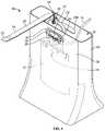
- a first exemplary product bag retention assembly 10safeguards against leakage of a product bag 12 , such as a night-time drainage bag that is attached to a patient or to a drainage bag connected to the patient via a tube 14 .
- the product bag 12may be used by an ostomy patient such that a first end (not shown) of the tube 14 is connected to the ostomy patient's ostomy bag via the tube 14 to collect fluids, and a second end 16 of the tube 14 is in fluid communication with an interior chamber of the product bag 12 .
- the product bag 12may be used by a catheter patient and is connected to the catheter patient's drainage bag via the tube 14 .
- a mounting device 26(e.g., first and second mounting arms) of the product bag 12 is attached to the handle 22 of the assembly 10 to hang the product bag 12 from the handle 22 .
- the handle 22is partially disposed within the bag 24 such that the product bag 12 is suspended within a chamber 25 defined by a wall 29 of the bag 24 .
- the bag 24is a reusable and/or disposable bag that is sized to surround the product bag 12 and catch any fluid leaking from the product bag 12 (e.g., through a loose valve or leaking tube).
- a platform 27 of the handle 22is disposed within a handle defined by a hole 28 A ( FIG. 2 ) formed in the wall 29 of the bag 24 , and, optionally, a ring 30 is removably coupled to the handle 22 to clamp the bag 24 between the ring 30 and the handle 22 .
- the brace 18which is a rod 18 , may be inserted between two surfaces of a piece of furniture, for example, between a box spring and a mattress of a typical bed, to securely suspend the product bag 12 in an upright position, above the ground, and away from the piece of furniture.
- the product bag 12When the product bag 12 is attached to the assembly 10 , the product bag 12 is kept out of the way from the patient, is discreetly suspended with the security bag 24 from a bedside or other piece of furniture, and remains connected to the patient to collect an overflow of fluid while the patient rests.
- Coupledand “connected” along with their derivatives.
- some examplesmay be described using the term “coupled” to indicate that two or more elements are in direct physical contact.
- the term “coupled,” however,may also mean that two or more elements are not in direct contact with each other, but yet still co-operate or interact with each other.
- the disclosed examplesare not limited in this context.
- the product bag 12may be coupled to the handle 22 before attaching the handle 22 to the security bag 24 or to the rod 18 .
- the product bag 12can hang directly from the handle 22 and can be used separately from the assembly 10 (i.e., without using the rod 18 or the bag 24 ) to transport the product bag 12 .
- a patientmay carry the product bag 12 to the bathroom to empty and rinse the product bag 12 before using the product bag 12 again.
- the rod 18remains attached to a piece of furniture so that the patient can easily connect the handle 22 to the rod 18 for use.
- the security bag 24 of the illustrated examplemay prop against a ground surface or may be spaced away from the ground surface when suspended from the rod 18 .
- the security bag 24includes first and second holes 28 A, 28 B, however, in other examples, the holes 28 A, 28 B may instead be slits formed in the wall 29 of the bag 24 .
- the security bag 24may not have any holes, but is instead capable of being trapped between the ring 30 and the handle 22 and/or cut to form holes to accommodate the platform 27 .
- the security bag 24is made of a plastic material that is leak-proof and durable to hold a product bag 12 full of fluid without breaking or leaking.
- the rod 18includes a first end 32 , a second end 34 defining a hook 36 , and a body 38 extending between the first end 32 and the second end 34 .
- the body 38 of the rod 18is generally flat and relatively thin to discreetly fit between two horizontal surfaces of a piece of furniture without noticeably affecting the comfort or feel of the furniture.
- the first end 32is slightly bent upward to provide resistance to the rod 18 so that the rod 18 does not pull out of the furniture when added weight of fluid is in the bag 12 .
- the first end 32 of the rod 18may be ribbed to provide added resistance and to frictionally engage the rod 18 with the horizontal surfaces of the piece of furniture.
- the body 38has a flat first surface 40 , and a spine 42 extending from a second surface 44 .
- the spine 42is a centrally-located ridge protruding from the second surface 44 and extends at least partially along the body 38 of the rod 18 for added structural support and to provide rigidity such that the rod 18 cantilevers a suspended product bag 12 without snapping or permanently deforming.
- the second end 34 of the rod 18is bent downwardly and away from the flat portion of the body 38 at substantially a right angle before curving to form the hook 36 .
- the hook 36curves outwardly (i.e., away from the first end 32 ) to flexibly receive the handle 22 of the assembly 10 .
- the hook 36may be shaped differently and may instead curve inwardly toward the first end 32 of the rod 18 .
- the hook 36may instead be a loop, clasp, or other structure that securely receives the handle 22 defined by the holes 28 A, 28 B extending through the wall 29 of the bag 24 .
- the product bag 12may hang directly from the hook 36 without the use of the security bag 24 .
- the hook 36is configured to slightly deform by opening in a direction H to receive the handle 22 before returning to its initially closed configuration.
- the handle 22engages the hook 36 by forcing the hook 36 to open in the H direction before the hook returns to its initial configuration.
- the hook 36securely retains the handle 22 to the rod 18 .
- the hook 36has a width W 1 that is sized to fit in a notch 46 ( FIG. 2 ) formed in the handle 22 such that the hook 36 securely fits into the notch 46 and keeps the handle 22 from sliding relative to the hook 36 .
- the hook 36may couple to the handle 22 by a snap-fit connection, and more particularly, the hook 36 may snap-fit into the notch 46 of the handle 22 .
- To remove the handle 22 from the rod 18the hook 36 is held relative to the handle 22 while the handle 22 is lifted upwardly and out of the hook 36 .
- the hook 36flexibly bends once more to remove the handle 22 from the rod 18 .
- the support brace 18is a rod that may be a flexible or rigid material.
- the support brace 18may be a belt or a strap made of a woven or flexible material such as, for example, fabric, polymer, metal, or a combination of materials.
- the support brace 18would include a locking component, such as a buckle, that would secure the belt around the piece of furniture such that a portion of the belt would protrude from the piece of furniture to removably couple to the product bag 12 .
- the handle 22which is more clearly shown in FIGS. 5 - 7 , includes a grip portion 50 and a support portion 54 extending from the grip portion 50 .
- the grip portion 50is shaped for a user to comfortably hold the handle 22 and defines an opening 58 .
- the opening 58is sized to receive a person's hand and also to receive the hook 36 to couple the hook 36 to the handle 22 .
- the notch 46 of the handle 22is sized to receive the hook 36 of the rod 18 .
- the notch 46is formed in the grip portion 50 and is adjacent to the opening 58 of the handle 22 .
- the support portion 54includes a base plate 62 stepped inwardly relative to the grip portion 54 of the handle 22 and includes a first surface 66 ( FIG. 5 ) and a second surface 70 ( FIGS. 6 and 7 ).
- the grip portion 50provides a curved grip with a tubular body, and the base plate 62 is flat by comparison.
- the grip portion 50meets the support portion 54 at a seam 72 , which is sloped to smoothly integrate the rounded grip portion 50 with the flat base plate 62 of the handle 22 .
- the seam 72may align with an opening of the bag 24 , as shown in FIG. 1 .
- the grip portion 50 and the support portion 54are integrally formed, however, in other examples, the grip portion 50 and the support portion 54 may be separate components that are securely coupled by fasteners, welding, adhesive, or other suitable methods.
- the handle 22includes the platform 27 that is operatively coupled to the support portion 54 , and is configured to receive and support a mounting device (e.g., mounting arms 26 ) of a product bag 12 .
- the platform 27couples to the security bag 24 by extending through one of the holes 28 A, 28 B (e.g., defining handles) formed in the wall 29 of the bag 24 .
- a first portion 76 of the platform 27extends away from the first surface 66 of the base plate 62 a length L 1 .
- the platform 27includes an aperture arrangement 78 including various apertures sized and shaped to receive a variety of different mounting devices of product bags 12 commonly used in the medical industry.
- a second portion 80 of the platform 27extends away from the second surface 70 of the base plate 72 a length L 2 .
- the length L 2 of the second portion 80is greater than the length L 1 of the first portion 76 , however, in other examples, the platform 27 may extend equally away from either surface 66 , 70 of the base plate 62 .
- a hook 82Adjacent a distal edge of the platform 27 , a hook 82 curves upwardly and inwardly toward the base plate 62 before curving in a perpendicular direction relative to the platform 27 .
- the hook 82is configured to retain a top edge of the second hole 28 B of the bag 24 (e.g., the handle of the bag 24 ).
- the hook 82is formed in the second portion 80 of the platform 27 . In this way, the hook 82 is configured to partially close the security bag 24 around the handle 22 and the product bag 12 when the first portion 76 of the platform 27 is secured to the security bag 24 .
- the platform 27is shaped to extend through at least one hole 28 A, 28 B formed in the bag 24 such that the support portion 54 of the handle 22 is disposed within the bag 24 and the grip portion 50 is outside of the bag 24 , as shown in FIG. 1 .
- the first portion 76 of the platform 27protrudes through the first hole 28 A in the bag 24
- the second portion 80 of the platform 27is configured to protrude through the second hole 28 B in the bag 24 .
- the safety bag 24may be secured directly to the rod 18 rather than directly coupled to the platform 27 .
- the safety bag 24may include a drawstring, adhesive, or other fastening device that permits a user to cinch the bag 24 around the rod 18 without securing the bag 24 to the platform 27 .
- the aperture arrangement 78 of the platform 27includes a plurality of apertures to receive different mounting devices of various product bags 12 .
- the aperture arrangement 78 of the platform 27includes first and second semi-circular apertures 83 , and a guide plate 84 defining first, second, and third vertical slots 86 , 88 , and 90 , and a horizontal rectangular opening 94 disposed beneath and connected to the vertical slots 86 , 88 , 90 .
- the guide plate 84is disposed at an outer edge of the first portion 76 and extends in a perpendicular direction relative to the length L 1 of the platform 27 . As more clearly shown in FIG.
- the first, second, and third slots 86 , 88 , and 90 formed in the guide plate 84are different sizes.
- the first and third slots 86 and 90are identical and evenly spaced from the second vertical slot 88 , which is centrally located relative to the handle 22 .
- the second slot 88is also slightly wider in both vertical and horizontal directions (in FIG. 7 ).
- the handle 22is symmetrical about a centerline axis X, and the second vertical slot 88 is parallel relative to the axis X.
- the first and second semi-circular apertures 83are configured to receive the mounting arms 26 of the product bag 12 .
- the platform 27 of the illustrated exampleis also configured to receive mounting devices (e.g., strings, hooks, ties, rings) of a number of different product bags manufactured by, for example, Rusch, Medline, Dover, Hollister, Bard, and Coveen.
- the aperture arrangement 78may be configured differently in other examples, and may include more or less apertures than what is illustrated.
- the guide plate 84may be removably attached to the base plate 62 such that the platform 27 can be adaptable to a particular product bag manufacturer.
- the product bag 12may be directly attached to the rod 18 instead mounting to the platform 27 .
- the platform 27 of the handle 22is removably coupled to the bag 24 by securing the ring 30 of FIG. 8 around an outer perimeter of the platform 27 and clamping a portion of the security bag 24 between the ring 30 and the handle 22 .
- the platform 27has an oval-shaped perimeter to match an oval opening 100 of the ring 30 , and engages with an upper ledge 102 and a lower ledge 104 of the platform 27 .
- the upper ledge 102 of the first portion 76 of the platform 27includes first and second pegs 110 , 114 that engage a linear portion 106 of the ring 30 .
- the pegs 110 , 114protrude from the ledge 102 of the platform 27 to securably engage the ring 30 between the pegs 110 , 114 and the first surface 66 of the base plate 62 .
- the pegs 110 , 114are spaced away from the first surface 66 of the base plate 62 by a gap G that is sized to receive the linear portion 106 of the ring 30 .
- the ring 30may be pushed downward and toward the platform 27 to engage a flexible latch 118 .
- the latch 118has an angled end 120 and is formed in the lower ledge 104 the platform 27 , and therefore is disposed below the upper ledge 102 .
- the latch 118is configured to slightly deform (e.g., flex, bend, deflect) upward in a direction J before returning to its original, unbiased position. By returning back to its initial position, the latch 118 securely retains the ring 30 to the platform 27 and the angled end 120 engages the ring 30 .
- the linear portion 106 of the ring 30is inserted into the gap G defined between the platform 27 and the base plate 62 , and a tab 122 of the ring 30 is pivoted downward and inward relative to the platform 27 until the ring 30 engages the latch 118 of the platform 27 .
- the ring 30pushes the latch 118 upward (in the J direction) until the angled end 120 of the latch 118 snaps against the ring 30 .
- the latch 118may be pushed upward in the J direction to disengage the ring 30 from the platform 27 , and a user may pull the tab 122 away from the latch 118 .
- the ring 30 and the platform 27may removably couple by other coupling methods.
- the pegs 110 , 114are positioned above and on either side of the guide plate 84 , however, in other examples, the platform 27 may include one peg or more than two pegs protruding from different locations around the perimeter of the platform 27 .
- the platform 27may be a separate component from the handle 22 such that the platform 27 is disposed within a cut-out (e.g., aperture, opening) formed in the base plate 62 .
- the cut-outmay be sized and shaped to receive the oval perimeter of the platform 27 , the first and second pegs 110 , 114 , the deflecting latch 118 , and the hook 82 when sliding the platform 27 into the cut-out of the base plate 62 . For example, as shown in FIG.
- the base plate 62includes first and second cut-outs 130 , 134 that are shaped to receive the first and second pegs 110 , 114 , a third cut-out 138 that is shaped to receive the latch 118 and to permit the latch 118 to deflect in the J direction, and a fourth cut-out 142 that is shaped to receive the hook 82 of the platform 27 .
- the platform 27is inserted through the cut-out of the base plate 62 until the length L 1 of the first portion 76 extends from the first surface 66 of the base plate 62 .
- the ring 30 and the platform 27are oval to facilitate coupling the ring 30 to the platform 27 .
- the platform 27 and the ring 30may have a different geometry and shape, such as, for example, rectangular, circular, or polygonal.
- the second exemplary product bag retention assembly 210includes a second exemplary rod 218 and a second exemplary platform 227 that may be used with the security bag 24 and product bag 12 of FIGS. 1 and 2 to suspend the product bag 12 from a piece of furniture in an upright position.
- the second exemplary rod 218 and second exemplary platform 227are similar to the rod 18 and platform 27 , respectively, of the first exemplary product bag retention assembly 10 of FIGS. 1 - 7 .
- the same or similar components of the second exemplary rod 218will retain the same reference numbers as outlined above with respect to the first exemplary rod 18 although the reference numbers will be increased by 200.
- the same or similar components of the second exemplary platform 227will retain the same reference numbers as outlined above with respect to the first exemplary platform 27 , although the reference numbers will be increased by 200.
- the second exemplary rod 218 and the second exemplary platform 227differ from the first exemplary rod 18 and first exemplary platform 27 , respectively, in the manner discussed below.
- the second exemplary rod 218includes a first end 232 that is configured to engage with a piece of furniture and a second end 234 that is operatively coupled to the platform 227 .
- the rod 218differs from the first exemplary rod 18 as the second exemplary rod 218 does not provide a hook 36 .
- the second end 234 of the rod 218is fastened to the platform 227 such that a mounting device 26 of a product bag 12 may be directly mounted to the rod 218 via the platform 227 .
- the second end 234 of the rod 218is integrally formed with the platform 227 . Similar to the first exemplary platform 27 of FIGS.
- the second exemplary platform 227is arranged to clamp a portion of the security bag 24 between the platform 227 and the ring 30 when the ring 30 is coupled to first and second pegs 310 , 314 and a latch 318 of the platform 227 .
- the platform 227 of FIG. 9includes a flange 262 , which surrounds the oval-shaped perimeter of the platform 227 and also serves to separate a first portion 276 of the platform 227 from a second portion 280 of the platform 227 .
- a method of assembling and suspending a product bag 12 from a piece of furnituregenerally includes the steps of providing the rod 18 , 218 in which the second end 34 , 234 is operatively coupled to the platform 27 , 227 for receiving a mounting device 26 of the product bag 12 , and disposing the first end 32 , 232 of the rod 18 , 218 between a first surface and a second surface of a piece of furniture such that the second end 34 , 234 of the rod 18 , 218 is spaced away from the piece of furniture.
- first end 32 , 232 of the rod 18 , 218may be inserted between a box spring and a mattress of a typical bed to suspend the product bag 12 from the bed.
- first end 32 , 232 of the rod 18 , 218may be inserted between a chair or couch frame and a cushion.
- the product bag 12is coupled to the platform 27 , 227 before inserting the rod 18 , 218 into the piece of furniture.
- the product bag 12is coupled to the platform 27 , 227 such that the product bag 12 is suspended outwardly and away from the piece of furniture and hangs from the platform 27 , 227 in an upright position.
- the product bag 12may be coupled to the platform 27 , 227 by sliding the mounting device 26 of the product bag 12 through an aperture (e.g., the aperture arrangements 78 , 278 ) formed in the platform 27 , 227 .
- the security bag 24is coupled to the platform 27 , 227 by disposing the first portion 76 , 276 of the platform 27 , 227 through the hole 28 A in the bag 24 .
- the ring 30is securely attached to the platform 27 , 227 such that a portion of the security bag 24 is clamped between the ring 30 and the platform 27 , 227 .
- the bag 24may be attached to the platform 27 , 227 prior to mounting the product bag 12 to the platform 27 , 227 .
- the methodincludes removing the ring 30 from the platform 27 , 227 and removing the security bag 24 from the platform 27 , 227 .
- a second security bag 24is then coupled to the platform 27 , 227 by disposing a portion of the platform 27 , 227 through a hole 28 A in the second bag 24 .
- the ring 30may again be secured to the platform 27 , 227 to clamp a portion of the second bag 24 between the ring 30 and the platform 27 , 227 .
- the platform 27is coupled to the support portion 54 of the handle 22 of the first exemplary product bag retention assembly 10 .
- the handle 22is coupled to the hook 36 of the rod 18 by engaging the handle 22 with the hook 36 .
- the handle 22couples to the hook 36 by snap-fitting the hook 36 into the notch 46 formed the handle 22 .
- the product bag 12can be mounted to the handle 22 before or after disposing the product bag 12 into the bag 24 .
- the ring 30may securably coupled to the handle 22 , thereby clamping the bag 24 between the handle 22 and the ring 30 .
- the handle 22is removable from the disposable bag 24 by removing the ring 30 and attaching the handle 22 of a different plastic bag 24 .
- the handle 22By removing the handle 22 from the hook 36 of the rod 18 , the patient may carry the product bag 12 to the bathroom to empty and rinse the product bag 12 before using the product bag 12 again.
- the rod 18remains attached to the piece of furniture so that the patient can easily connect the handle 22 to the hook 36 for use.
- the first and second exemplary product bag retention assemblies 10 , 210may provide a patient with confidence that their connected medical product bag is safely secured and out of the way while the patient rests. As described herein, the product bag retention assembly 10 , 210 safeguards against accidental leaks of the connected product bag 12 while the patient is asleep. In case the product bag 12 were to leak, the security bag 24 guards against any spilling on the floor or furniture. The patient can easily disassemble the assembly 10 , 210 , discard or wash the removable disposable bag 24 , and replace the security bag 24 with a new bag 24 or a clean bag 24 .
- the rod 18 , 218may be light-weight and easy to use such that a patient can travel with it and use it with a variety of different pieces of furniture.
- the slim body 38 , 238 of the rod 18 , 218permits a patient to slip the assembly 10 , 210 between two horizontal surfaces without worrying that the product bag 12 will fall, turn-over, or become detached while the patient sleeps.
- the design of the assembly 10 , 210is compact such the patient can place the security bag 24 flat against a bed, discreetly hidden from view.
- the flexible coupling mechanismse.g., the hook 36 and handle 22 , the platform 27 , 227 and the ring 30 ) facilitate easy assembly and disassembly of the product bag 12 from the handle 22 and/or from the rod 18 , 218 .
- the different components of the assemblies 10 , 210are preferably made of a durable plastic, such as polyethylene, that may be formed by injection molding, thermoforming, or compression molding, but may instead be formed of any other suitable and durable material including metal, fiberglass, or other similar materials, or any combination of these materials.
- the components of the assemblies 10 , 210may be made using an additive manufacturing (AM) technique or process that builds three-dimensional objects by adding successive layers of material on a material or receiving surface.
- the AM techniquemay be performed by any suitable machine or combination of machines.
- the AM techniquemay typically involve or use a computer, three-dimensional modeling software (e.g., Computer Aided Design, or CAD, software), machine equipment, and layering material.
- CADComputer Aided Design
- the machine equipmentmay read in data from the CAD file and layer or add successive layers of liquid, powder, sheet material (for example) in a layer-upon-layer fashion to fabricate a three-dimensional object.
- the AM techniquemay include any of several techniques or processes, such as, for example, a stereolithography (“SLA”) process, digital light processing (“DLP”), a fused deposition modeling (“FDM”) process, a multi-jet modeling (“MJM”) process, a selective laser sintering (“SLS”) process, a selective laser melting (“SLM”) process, an electronic beam melting (“EBM”) process, and an arc welding AM process.
- the AM processmay include a directed energy laser deposition process.
- Such a directed energy laser deposition processmay be performed by a multi-axis computer-numerically-controlled (“CNC”) lathe with directed energy laser deposition capabilities.
- CNCcomputer-numerically-controlled
- Other manufacturing techniquesmay be utilized to create the assemblies 10 , 210 according to the present disclosure, and are not limited to the techniques herein.
Landscapes
- Health & Medical Sciences (AREA)
- General Health & Medical Sciences (AREA)
- Veterinary Medicine (AREA)
- Public Health (AREA)
- Life Sciences & Earth Sciences (AREA)
- Animal Behavior & Ethology (AREA)
- Nursing (AREA)
- Engineering & Computer Science (AREA)
- Heart & Thoracic Surgery (AREA)
- Biomedical Technology (AREA)
- Vascular Medicine (AREA)
- Epidemiology (AREA)
- Orthopedic Medicine & Surgery (AREA)
- Mechanical Engineering (AREA)
- Hematology (AREA)
- Anesthesiology (AREA)
- Purses, Travelling Bags, Baskets, Or Suitcases (AREA)
- Supports Or Holders For Household Use (AREA)
- Auxiliary Apparatuses For Manual Packaging Operations (AREA)
- Supplying Of Containers To The Packaging Station (AREA)
- Bag Frames (AREA)
Abstract
Description
Claims (13)
Priority Applications (3)
| Application Number | Priority Date | Filing Date | Title |
|---|---|---|---|
| US16/193,989US11540962B2 (en) | 2018-11-16 | 2018-11-16 | Product bag retention assembly |
| EP19209317.7AEP3653181A3 (en) | 2018-11-16 | 2019-11-15 | Product bag retention assembly |
| US18/068,266US20230117017A1 (en) | 2018-11-16 | 2022-12-19 | Product bag retention assembly |
Applications Claiming Priority (1)
| Application Number | Priority Date | Filing Date | Title |
|---|---|---|---|
| US16/193,989US11540962B2 (en) | 2018-11-16 | 2018-11-16 | Product bag retention assembly |
Related Child Applications (1)
| Application Number | Title | Priority Date | Filing Date |
|---|---|---|---|
| US18/068,266ContinuationUS20230117017A1 (en) | 2018-11-16 | 2022-12-19 | Product bag retention assembly |
Publications (2)
| Publication Number | Publication Date |
|---|---|
| US20200155394A1 US20200155394A1 (en) | 2020-05-21 |
| US11540962B2true US11540962B2 (en) | 2023-01-03 |
Family
ID=68583110
Family Applications (2)
| Application Number | Title | Priority Date | Filing Date |
|---|---|---|---|
| US16/193,989Active2041-05-18US11540962B2 (en) | 2018-11-16 | 2018-11-16 | Product bag retention assembly |
| US18/068,266PendingUS20230117017A1 (en) | 2018-11-16 | 2022-12-19 | Product bag retention assembly |
Family Applications After (1)
| Application Number | Title | Priority Date | Filing Date |
|---|---|---|---|
| US18/068,266PendingUS20230117017A1 (en) | 2018-11-16 | 2022-12-19 | Product bag retention assembly |
Country Status (2)
| Country | Link |
|---|---|
| US (2) | US11540962B2 (en) |
| EP (1) | EP3653181A3 (en) |
Cited By (1)
| Publication number | Priority date | Publication date | Assignee | Title |
|---|---|---|---|---|
| GB2636328A (en)* | 2023-03-20 | 2025-06-18 | Optimum Medical Solutions Ltd | Container assembly |
Families Citing this family (1)
| Publication number | Priority date | Publication date | Assignee | Title |
|---|---|---|---|---|
| EP4262674A4 (en)* | 2021-01-26 | 2024-12-11 | Potrero Medical, Inc. | EQUIPMENT ADAPTER ARRANGEMENT AND EQUIPMENT STAND |
Citations (101)
| Publication number | Priority date | Publication date | Assignee | Title |
|---|---|---|---|---|
| US1876230A (en)* | 1930-08-28 | 1932-09-06 | Birdie O Horner | Tray mounting means for attachment to beds |
| US2557674A (en) | 1949-09-20 | 1951-06-19 | Gaylord R Hawkins | Appliance for sickrooms and other purposes |
| US2784423A (en)* | 1954-12-13 | 1957-03-12 | Carl C Droeger | Hospital-bed accessory |
| US2886036A (en)* | 1956-02-24 | 1959-05-12 | Russell W Price | Hospital drain bag |
| US2999387A (en)* | 1959-02-16 | 1961-09-12 | Falcon Plastics Company | Fluid tight container |
| US3180384A (en)* | 1963-05-29 | 1965-04-27 | Emil M Seifert | Litter bag |
| US3220434A (en) | 1964-12-23 | 1965-11-30 | Andrew B Young | Bedside hanger and surgical bag |
| US3231901A (en) | 1963-05-14 | 1966-02-01 | Floyd E Kennedy | Hospital drain bag hanger |
| US3254817A (en) | 1964-08-31 | 1966-06-07 | Frank J Bartz | Holder for surgical drainage bags |
| US3345023A (en)* | 1965-05-27 | 1967-10-03 | Resiflex Lab | Bedside drainage receptacle support means |
| US3371897A (en)* | 1965-07-22 | 1968-03-05 | Bard Inc C R | Drain bag support assembly |
| US3471871A (en)* | 1967-01-31 | 1969-10-14 | Fairchild Hiller Corp | Waste collection bags |
| US3534738A (en)* | 1964-10-13 | 1970-10-20 | Charles M Huck | Bedside and ambulatory portable drainage system |
| US3537109A (en)* | 1968-04-15 | 1970-11-03 | American Hospital Supply Corp | Hanger structure for medical liquid collection container |
| US3548827A (en)* | 1968-07-01 | 1970-12-22 | Allen J Abel | Body fluid drainage and collecting apparatus |
| US3716055A (en)* | 1971-08-02 | 1973-02-13 | Plastronics Inc | Support apparatus for a bedside drainage bag |
| US3809577A (en)* | 1971-03-10 | 1974-05-07 | Motala Verkstad Ab | Method of emptying drainage bags and apparatus for carrying out the method |
| US3865165A (en)* | 1973-10-25 | 1975-02-11 | Daniel S Glass | Universal faced body fluid drainage bag with universal drainage means |
| US4027842A (en)* | 1975-09-24 | 1977-06-07 | Baxter Travenol Laboratories, Inc. | Flexible hanger member for drainage bags and the like |
| US4178934A (en)* | 1977-12-27 | 1979-12-18 | G. D. Searle & Co. | Urine meter and collection assembly |
| US4194715A (en)* | 1977-12-27 | 1980-03-25 | G. D. Searle & Co. | Container support means |
| US4219177A (en)* | 1978-08-25 | 1980-08-26 | American Hospital Supply Corporation | Bed rail hanger system |
| US4235350A (en)* | 1979-08-20 | 1980-11-25 | Valentino Pearl T | Bed side rail container with removable liner |
| US4254771A (en)* | 1978-08-25 | 1981-03-10 | American Hospital Supply Corporation | Folded top urine bag with elongated stiffening panel |
| USRE30607E (en)* | 1979-06-18 | 1981-05-12 | Plastronics, Inc. | Combination urine meter and drainage receptacle |
| US4305405A (en)* | 1980-03-25 | 1981-12-15 | C. R. Bard, Inc. | Urine meter bag |
| US4312352A (en)* | 1980-01-29 | 1982-01-26 | C. R. Bard, Inc. | Hanger, hook and handle assembly for urinary drainage bag |
| US4317550A (en)* | 1979-09-17 | 1982-03-02 | Baxter Travenol Laboratories, Inc. | Apparatus for suspending a drainage bag |
| US4326521A (en)* | 1976-11-11 | 1982-04-27 | Marsan Arthur E | Appliance for the treatment of colostomy and the like |
| US4332252A (en)* | 1980-07-11 | 1982-06-01 | The Kendall Company | Drainage receptacle with support member |
| US4393880A (en)* | 1981-03-25 | 1983-07-19 | The Kendall Company | Device for collecting body liquids |
| US4496354A (en)* | 1981-11-23 | 1985-01-29 | Craig Medical Products Limited | Drainage bag assembly with drip tray |
| US4501584A (en)* | 1983-03-04 | 1985-02-26 | The Kendall Company | Liquid drainage system with formed hinged support sheet |
| US4534766A (en)* | 1982-04-16 | 1985-08-13 | Craig Medical Products Limited | Drainage bag for urine and support therefor |
| US4562984A (en) | 1983-08-08 | 1986-01-07 | Sherwood Medical Company | Drainage bag support |
| US4579126A (en)* | 1983-03-04 | 1986-04-01 | The Kendall Company | Liquid drainage system with emptying system |
| US4606736A (en)* | 1985-01-23 | 1986-08-19 | Van De Weghe Associates, Inc. | Cover assembly for closed bodily fluid drainage unit |
| US4650478A (en)* | 1983-06-28 | 1987-03-17 | The Kendall Company | Liquid drainage system having a hook support member |
| US4673401A (en)* | 1984-04-02 | 1987-06-16 | Jensen Ole R | Male incontinence device |
| US4731062A (en)* | 1986-06-20 | 1988-03-15 | The Kendall Company | Urine meter |
| US4773768A (en) | 1987-12-01 | 1988-09-27 | Leeper Charles E | Tube retaining and disposal container |
| US4787584A (en) | 1988-03-11 | 1988-11-29 | David Palmer | Trash bag supporting device |
| US4850375A (en)* | 1987-11-09 | 1989-07-25 | The Kendall Company | Urine meter with tilting guide |
| US4874387A (en)* | 1988-11-01 | 1989-10-17 | Boone Delores A | Cover for body fluid drainage bag and tubing |
| US4946451A (en)* | 1983-01-27 | 1990-08-07 | The Kendall Company | Liquid valve system |
| US4988062A (en)* | 1988-03-10 | 1991-01-29 | London Robert A | Apparatus, system and method for organizing and maintaining a plurality of medical catheters and the like |
| US5119675A (en)* | 1990-08-13 | 1992-06-09 | The Kendall Company | Liquid drainage system |
| US5282599A (en)* | 1992-12-02 | 1994-02-01 | Arpaia Josephine J | Portable urinal and receptacle for portable urinal |
| US5349710A (en) | 1992-10-15 | 1994-09-27 | Dunn William P | Flexible bag retaining device |
| US5375799A (en) | 1992-09-25 | 1994-12-27 | Hollister Incorporated | Collection bag hanger with rail width-adjustable hook arms |
| US5382244A (en)* | 1991-02-25 | 1995-01-17 | Baxter International Inc. | Stand alone control module |
| US5393113A (en)* | 1993-10-15 | 1995-02-28 | Sherwood Medical Company | Handle attachment for chest drainage unit |
| US5423782A (en) | 1994-06-17 | 1995-06-13 | Wolrich; Douglas H. | Disposable ostomy bag liner |
| US5472167A (en)* | 1994-01-26 | 1995-12-05 | Med-Safe Systems, Inc. | Secure mounting bracket for disposable sharps container |
| US5489281A (en)* | 1991-01-18 | 1996-02-06 | Alza Corporation | Process for controlling pathogens in container |
| US5527007A (en)* | 1993-08-24 | 1996-06-18 | Sherwood Medical Company | Movable hanger mount for chest drainage unit |
| US5651152A (en)* | 1996-04-16 | 1997-07-29 | Ritchie; Jane E. | Storage organizer for hospital bed |
| US5829723A (en)* | 1995-06-28 | 1998-11-03 | Medex, Inc. | Medical device mounting structure |
| US5836553A (en)* | 1996-02-08 | 1998-11-17 | Bergaila; Steven W. | Folding bag holder |
| US5938646A (en) | 1997-10-17 | 1999-08-17 | Carter; Thomas E. | Medical utility storage assembly for reusable medical equipment |
| US6109460A (en)* | 1996-11-26 | 2000-08-29 | Instrumentarium Corporation | Suspension rack |
| US6129684A (en)* | 1998-09-02 | 2000-10-10 | B. Braun Melsungen Ag | Urine measuring device |
| US20010011166A1 (en)* | 1999-04-30 | 2001-08-02 | Harper Derek J. | External medical drainage system having a stopcock attachable to a mounting assembly |
| US6423041B1 (en)* | 2000-07-31 | 2002-07-23 | Candace Lynn Grant | Catheter caddy |
| US6637938B2 (en)* | 2001-12-06 | 2003-10-28 | Deborah H. Watkins | Laundry apparatus |
| US6675998B2 (en)* | 2000-07-10 | 2004-01-13 | Camelbak Products, Inc. | Hydration system with improved fluid reservoir |
| US20050087660A1 (en)* | 2003-10-27 | 2005-04-28 | Nicholas Want | Method and apparatus for hanging a medical device |
| US20060011784A1 (en)* | 2002-04-10 | 2006-01-19 | Erik Liebermann | Receptacle mounting device |
| US7014077B2 (en)* | 2003-08-13 | 2006-03-21 | Nalge Nunc International | Portable container |
| US7090179B2 (en) | 2004-01-23 | 2006-08-15 | Dimaggio Edward G | Mounting assembly for a waste line of a medical treatment apparatus |
| US20070057134A1 (en)* | 2005-09-14 | 2007-03-15 | Pao-Hsien Cheng | Structure of an article holder |
| US20070107130A1 (en)* | 2005-11-16 | 2007-05-17 | Basim Elhabashy | Surgical coordinator for anesthesiologist and methods of use |
| US20070203463A1 (en)* | 2006-02-24 | 2007-08-30 | Larry Salvadori | Urine collection system with needleless sampling port |
| US20070215782A1 (en)* | 2006-03-17 | 2007-09-20 | Phung Trinh D | Chest drainage unit adjustable hanger and method |
| US7398951B1 (en)* | 2005-01-05 | 2008-07-15 | Vivian Sugalski | Urinal holder |
| US7462171B2 (en)* | 2006-02-24 | 2008-12-09 | Tyco Healthcare Group Lp | Urine collection bag with angled valve support |
| US20080319406A1 (en) | 2006-03-16 | 2008-12-25 | Yvette Garrett | Bedside caddy |
| US20090030384A1 (en)* | 2006-01-27 | 2009-01-29 | Medela Holding Ag | Fastening Device for a Drainage Container |
| US20090216206A1 (en)* | 2006-10-17 | 2009-08-27 | C. R. Bard, Inc. | Waste Management System |
| US7703723B1 (en)* | 2007-03-09 | 2010-04-27 | Charles Cooper | Bag support device |
| US7814590B2 (en) | 2008-11-25 | 2010-10-19 | Oregon Health & Science University | Accessory panel for diagnostic platform, patient bed and other support surfaces |
| US20110128152A1 (en)* | 2009-11-30 | 2011-06-02 | Frederic Bregeon | Device for monitoring the condition of a fluid receptacle |
| US8177097B2 (en)* | 2009-12-08 | 2012-05-15 | Camelbak Products, Llc | Personal hydration systems, dryer mechanisms for use with personal hydration systems, and methods of drying personal hydration system reservoirs |
| US20120216348A1 (en)* | 2009-10-30 | 2012-08-30 | Cox Larry E | Accessory bar for a treatment bed |
| US8267358B1 (en) | 2011-05-10 | 2012-09-18 | Letson Philip D | Bag holder |
| US20130094786A1 (en) | 2010-10-04 | 2013-04-18 | Medline Industries, Inc. | Cover for a Fluid Collection Device |
| US8430855B2 (en)* | 2006-12-06 | 2013-04-30 | Medline Industries, Inc. | Fluid collection system and methods of using same |
| US20130161350A1 (en)* | 2009-05-05 | 2013-06-27 | Eugene Murrieta | Medical patient oral hydration system |
| US8672402B1 (en)* | 2010-08-27 | 2014-03-18 | Aletha Arnold | Removable net baskets for child car seats |
| US9072637B1 (en)* | 2012-07-13 | 2015-07-07 | Kathleen F. Puri | Self leveling cradle and removable container |
| US9095222B2 (en)* | 2012-05-21 | 2015-08-04 | Amikam ASAF | Bedside storage caddy |
| US20160324708A1 (en)* | 2015-05-08 | 2016-11-10 | Jerry Ellis | Bed Rail Organizer |
| US20170121104A1 (en)* | 2015-11-01 | 2017-05-04 | Nicholas Michael Degnan | Waste Receptacle Attachment for Composting Kitchen Waste |
| US20170281836A1 (en)* | 2014-09-02 | 2017-10-05 | Medela Holding Ag | Suspension device of a drainage container |
| US20180049909A1 (en) | 2016-08-16 | 2018-02-22 | Althia Johnson | Ostomy leak proof protection bag |
| US20180245967A1 (en)* | 2016-05-13 | 2018-08-30 | Adaptec Medical Devices LLC | Fluid container measurement system |
| US20190358075A1 (en)* | 2018-05-22 | 2019-11-28 | Stryker Corporation | Urine Collection System For Use On Patient Support Apparatus |
| US20200030191A1 (en)* | 2018-07-25 | 2020-01-30 | Joseph Santillan | Adjustable Feeding Tube Holder |
| US20200306421A1 (en)* | 2019-04-01 | 2020-10-01 | Sterigear, Llc | Dual drainage bag, assemblies, and related methods |
| US20210080054A1 (en)* | 2018-06-19 | 2021-03-18 | Potrero Medical, Inc. | Equipment adaptor assembly and equipment stand |
| US20210138135A1 (en)* | 2019-11-12 | 2021-05-13 | Fresenius Medical Care Deutschland Gmbh | Blood Treatment Systems |
- 2018
- 2018-11-16USUS16/193,989patent/US11540962B2/enactiveActive
- 2019
- 2019-11-15EPEP19209317.7Apatent/EP3653181A3/ennot_activeWithdrawn
- 2022
- 2022-12-19USUS18/068,266patent/US20230117017A1/enactivePending
Patent Citations (103)
| Publication number | Priority date | Publication date | Assignee | Title |
|---|---|---|---|---|
| US1876230A (en)* | 1930-08-28 | 1932-09-06 | Birdie O Horner | Tray mounting means for attachment to beds |
| US2557674A (en) | 1949-09-20 | 1951-06-19 | Gaylord R Hawkins | Appliance for sickrooms and other purposes |
| US2784423A (en)* | 1954-12-13 | 1957-03-12 | Carl C Droeger | Hospital-bed accessory |
| US2886036A (en)* | 1956-02-24 | 1959-05-12 | Russell W Price | Hospital drain bag |
| US2999387A (en)* | 1959-02-16 | 1961-09-12 | Falcon Plastics Company | Fluid tight container |
| US3231901A (en) | 1963-05-14 | 1966-02-01 | Floyd E Kennedy | Hospital drain bag hanger |
| US3180384A (en)* | 1963-05-29 | 1965-04-27 | Emil M Seifert | Litter bag |
| US3254817A (en) | 1964-08-31 | 1966-06-07 | Frank J Bartz | Holder for surgical drainage bags |
| US3534738A (en)* | 1964-10-13 | 1970-10-20 | Charles M Huck | Bedside and ambulatory portable drainage system |
| US3220434A (en) | 1964-12-23 | 1965-11-30 | Andrew B Young | Bedside hanger and surgical bag |
| US3345023A (en)* | 1965-05-27 | 1967-10-03 | Resiflex Lab | Bedside drainage receptacle support means |
| US3371897A (en)* | 1965-07-22 | 1968-03-05 | Bard Inc C R | Drain bag support assembly |
| US3471871A (en)* | 1967-01-31 | 1969-10-14 | Fairchild Hiller Corp | Waste collection bags |
| US3537109A (en)* | 1968-04-15 | 1970-11-03 | American Hospital Supply Corp | Hanger structure for medical liquid collection container |
| US3548827A (en)* | 1968-07-01 | 1970-12-22 | Allen J Abel | Body fluid drainage and collecting apparatus |
| US3809577A (en)* | 1971-03-10 | 1974-05-07 | Motala Verkstad Ab | Method of emptying drainage bags and apparatus for carrying out the method |
| US3716055A (en)* | 1971-08-02 | 1973-02-13 | Plastronics Inc | Support apparatus for a bedside drainage bag |
| US3865165A (en)* | 1973-10-25 | 1975-02-11 | Daniel S Glass | Universal faced body fluid drainage bag with universal drainage means |
| US4027842A (en)* | 1975-09-24 | 1977-06-07 | Baxter Travenol Laboratories, Inc. | Flexible hanger member for drainage bags and the like |
| US4326521A (en)* | 1976-11-11 | 1982-04-27 | Marsan Arthur E | Appliance for the treatment of colostomy and the like |
| US4178934A (en)* | 1977-12-27 | 1979-12-18 | G. D. Searle & Co. | Urine meter and collection assembly |
| US4194715A (en)* | 1977-12-27 | 1980-03-25 | G. D. Searle & Co. | Container support means |
| US4219177A (en)* | 1978-08-25 | 1980-08-26 | American Hospital Supply Corporation | Bed rail hanger system |
| US4254771A (en)* | 1978-08-25 | 1981-03-10 | American Hospital Supply Corporation | Folded top urine bag with elongated stiffening panel |
| USRE30607E (en)* | 1979-06-18 | 1981-05-12 | Plastronics, Inc. | Combination urine meter and drainage receptacle |
| US4235350A (en)* | 1979-08-20 | 1980-11-25 | Valentino Pearl T | Bed side rail container with removable liner |
| US4317550A (en)* | 1979-09-17 | 1982-03-02 | Baxter Travenol Laboratories, Inc. | Apparatus for suspending a drainage bag |
| US4312352A (en)* | 1980-01-29 | 1982-01-26 | C. R. Bard, Inc. | Hanger, hook and handle assembly for urinary drainage bag |
| US4305405A (en)* | 1980-03-25 | 1981-12-15 | C. R. Bard, Inc. | Urine meter bag |
| US4332252A (en)* | 1980-07-11 | 1982-06-01 | The Kendall Company | Drainage receptacle with support member |
| US4393880A (en)* | 1981-03-25 | 1983-07-19 | The Kendall Company | Device for collecting body liquids |
| US4496354A (en)* | 1981-11-23 | 1985-01-29 | Craig Medical Products Limited | Drainage bag assembly with drip tray |
| US4534766A (en)* | 1982-04-16 | 1985-08-13 | Craig Medical Products Limited | Drainage bag for urine and support therefor |
| US4946451A (en)* | 1983-01-27 | 1990-08-07 | The Kendall Company | Liquid valve system |
| US4501584A (en)* | 1983-03-04 | 1985-02-26 | The Kendall Company | Liquid drainage system with formed hinged support sheet |
| US4579126A (en)* | 1983-03-04 | 1986-04-01 | The Kendall Company | Liquid drainage system with emptying system |
| US4650478A (en)* | 1983-06-28 | 1987-03-17 | The Kendall Company | Liquid drainage system having a hook support member |
| US4562984A (en) | 1983-08-08 | 1986-01-07 | Sherwood Medical Company | Drainage bag support |
| US4673401A (en)* | 1984-04-02 | 1987-06-16 | Jensen Ole R | Male incontinence device |
| US4606736A (en)* | 1985-01-23 | 1986-08-19 | Van De Weghe Associates, Inc. | Cover assembly for closed bodily fluid drainage unit |
| US4731062A (en)* | 1986-06-20 | 1988-03-15 | The Kendall Company | Urine meter |
| US4850375A (en)* | 1987-11-09 | 1989-07-25 | The Kendall Company | Urine meter with tilting guide |
| US4773768A (en) | 1987-12-01 | 1988-09-27 | Leeper Charles E | Tube retaining and disposal container |
| US4988062A (en)* | 1988-03-10 | 1991-01-29 | London Robert A | Apparatus, system and method for organizing and maintaining a plurality of medical catheters and the like |
| US4787584A (en) | 1988-03-11 | 1988-11-29 | David Palmer | Trash bag supporting device |
| US4874387A (en)* | 1988-11-01 | 1989-10-17 | Boone Delores A | Cover for body fluid drainage bag and tubing |
| US5119675A (en)* | 1990-08-13 | 1992-06-09 | The Kendall Company | Liquid drainage system |
| US5489281A (en)* | 1991-01-18 | 1996-02-06 | Alza Corporation | Process for controlling pathogens in container |
| US5382244A (en)* | 1991-02-25 | 1995-01-17 | Baxter International Inc. | Stand alone control module |
| US5375799A (en) | 1992-09-25 | 1994-12-27 | Hollister Incorporated | Collection bag hanger with rail width-adjustable hook arms |
| US5349710A (en) | 1992-10-15 | 1994-09-27 | Dunn William P | Flexible bag retaining device |
| US5282599A (en)* | 1992-12-02 | 1994-02-01 | Arpaia Josephine J | Portable urinal and receptacle for portable urinal |
| US5527007A (en)* | 1993-08-24 | 1996-06-18 | Sherwood Medical Company | Movable hanger mount for chest drainage unit |
| US5393113A (en)* | 1993-10-15 | 1995-02-28 | Sherwood Medical Company | Handle attachment for chest drainage unit |
| US5472167A (en)* | 1994-01-26 | 1995-12-05 | Med-Safe Systems, Inc. | Secure mounting bracket for disposable sharps container |
| US5423782A (en) | 1994-06-17 | 1995-06-13 | Wolrich; Douglas H. | Disposable ostomy bag liner |
| US5829723A (en)* | 1995-06-28 | 1998-11-03 | Medex, Inc. | Medical device mounting structure |
| US5836553A (en)* | 1996-02-08 | 1998-11-17 | Bergaila; Steven W. | Folding bag holder |
| US5651152A (en)* | 1996-04-16 | 1997-07-29 | Ritchie; Jane E. | Storage organizer for hospital bed |
| US6109460A (en)* | 1996-11-26 | 2000-08-29 | Instrumentarium Corporation | Suspension rack |
| US5938646A (en) | 1997-10-17 | 1999-08-17 | Carter; Thomas E. | Medical utility storage assembly for reusable medical equipment |
| US6129684A (en)* | 1998-09-02 | 2000-10-10 | B. Braun Melsungen Ag | Urine measuring device |
| US20010011166A1 (en)* | 1999-04-30 | 2001-08-02 | Harper Derek J. | External medical drainage system having a stopcock attachable to a mounting assembly |
| US6675998B2 (en)* | 2000-07-10 | 2004-01-13 | Camelbak Products, Inc. | Hydration system with improved fluid reservoir |
| US6423041B1 (en)* | 2000-07-31 | 2002-07-23 | Candace Lynn Grant | Catheter caddy |
| US6637938B2 (en)* | 2001-12-06 | 2003-10-28 | Deborah H. Watkins | Laundry apparatus |
| US20060011784A1 (en)* | 2002-04-10 | 2006-01-19 | Erik Liebermann | Receptacle mounting device |
| US7014077B2 (en)* | 2003-08-13 | 2006-03-21 | Nalge Nunc International | Portable container |
| US20050087660A1 (en)* | 2003-10-27 | 2005-04-28 | Nicholas Want | Method and apparatus for hanging a medical device |
| US7090179B2 (en) | 2004-01-23 | 2006-08-15 | Dimaggio Edward G | Mounting assembly for a waste line of a medical treatment apparatus |
| US7398951B1 (en)* | 2005-01-05 | 2008-07-15 | Vivian Sugalski | Urinal holder |
| US20070057134A1 (en)* | 2005-09-14 | 2007-03-15 | Pao-Hsien Cheng | Structure of an article holder |
| US20070107130A1 (en)* | 2005-11-16 | 2007-05-17 | Basim Elhabashy | Surgical coordinator for anesthesiologist and methods of use |
| US20090030384A1 (en)* | 2006-01-27 | 2009-01-29 | Medela Holding Ag | Fastening Device for a Drainage Container |
| US7462171B2 (en)* | 2006-02-24 | 2008-12-09 | Tyco Healthcare Group Lp | Urine collection bag with angled valve support |
| US20070203463A1 (en)* | 2006-02-24 | 2007-08-30 | Larry Salvadori | Urine collection system with needleless sampling port |
| US20080319406A1 (en) | 2006-03-16 | 2008-12-25 | Yvette Garrett | Bedside caddy |
| US8109914B2 (en)* | 2006-03-16 | 2012-02-07 | Yvette Garrett | Bedside caddy |
| US20070215782A1 (en)* | 2006-03-17 | 2007-09-20 | Phung Trinh D | Chest drainage unit adjustable hanger and method |
| US20170020711A1 (en) | 2006-10-17 | 2017-01-26 | C. R. Bard, Inc. | Waste management system |
| US20090216206A1 (en)* | 2006-10-17 | 2009-08-27 | C. R. Bard, Inc. | Waste Management System |
| US8430855B2 (en)* | 2006-12-06 | 2013-04-30 | Medline Industries, Inc. | Fluid collection system and methods of using same |
| US7703723B1 (en)* | 2007-03-09 | 2010-04-27 | Charles Cooper | Bag support device |
| US7814590B2 (en) | 2008-11-25 | 2010-10-19 | Oregon Health & Science University | Accessory panel for diagnostic platform, patient bed and other support surfaces |
| US20130161350A1 (en)* | 2009-05-05 | 2013-06-27 | Eugene Murrieta | Medical patient oral hydration system |
| US20120216348A1 (en)* | 2009-10-30 | 2012-08-30 | Cox Larry E | Accessory bar for a treatment bed |
| US20110128152A1 (en)* | 2009-11-30 | 2011-06-02 | Frederic Bregeon | Device for monitoring the condition of a fluid receptacle |
| US8177097B2 (en)* | 2009-12-08 | 2012-05-15 | Camelbak Products, Llc | Personal hydration systems, dryer mechanisms for use with personal hydration systems, and methods of drying personal hydration system reservoirs |
| US8672402B1 (en)* | 2010-08-27 | 2014-03-18 | Aletha Arnold | Removable net baskets for child car seats |
| US20130094786A1 (en) | 2010-10-04 | 2013-04-18 | Medline Industries, Inc. | Cover for a Fluid Collection Device |
| US8267358B1 (en) | 2011-05-10 | 2012-09-18 | Letson Philip D | Bag holder |
| US9095222B2 (en)* | 2012-05-21 | 2015-08-04 | Amikam ASAF | Bedside storage caddy |
| US9072637B1 (en)* | 2012-07-13 | 2015-07-07 | Kathleen F. Puri | Self leveling cradle and removable container |
| US20170281836A1 (en)* | 2014-09-02 | 2017-10-05 | Medela Holding Ag | Suspension device of a drainage container |
| US20160324708A1 (en)* | 2015-05-08 | 2016-11-10 | Jerry Ellis | Bed Rail Organizer |
| US20170121104A1 (en)* | 2015-11-01 | 2017-05-04 | Nicholas Michael Degnan | Waste Receptacle Attachment for Composting Kitchen Waste |
| US20180245967A1 (en)* | 2016-05-13 | 2018-08-30 | Adaptec Medical Devices LLC | Fluid container measurement system |
| US20180049909A1 (en) | 2016-08-16 | 2018-02-22 | Althia Johnson | Ostomy leak proof protection bag |
| US20190358075A1 (en)* | 2018-05-22 | 2019-11-28 | Stryker Corporation | Urine Collection System For Use On Patient Support Apparatus |
| US20210080054A1 (en)* | 2018-06-19 | 2021-03-18 | Potrero Medical, Inc. | Equipment adaptor assembly and equipment stand |
| US20200030191A1 (en)* | 2018-07-25 | 2020-01-30 | Joseph Santillan | Adjustable Feeding Tube Holder |
| US20200306421A1 (en)* | 2019-04-01 | 2020-10-01 | Sterigear, Llc | Dual drainage bag, assemblies, and related methods |
| US20210138135A1 (en)* | 2019-11-12 | 2021-05-13 | Fresenius Medical Care Deutschland Gmbh | Blood Treatment Systems |
Non-Patent Citations (2)
| Title |
|---|
| European Patent Application No. 19209317, Partial European Search Report, dated Mar. 31, 2020. |
| European Patent Application No. 19209317.7, Extended European Search Report, dated Jul. 1, 2020. |
Cited By (1)
| Publication number | Priority date | Publication date | Assignee | Title |
|---|---|---|---|---|
| GB2636328A (en)* | 2023-03-20 | 2025-06-18 | Optimum Medical Solutions Ltd | Container assembly |
Also Published As
| Publication number | Publication date |
|---|---|
| US20200155394A1 (en) | 2020-05-21 |
| EP3653181A3 (en) | 2020-07-29 |
| US20230117017A1 (en) | 2023-04-20 |
| EP3653181A2 (en) | 2020-05-20 |
Similar Documents
| Publication | Publication Date | Title |
|---|---|---|
| US20230117017A1 (en) | Product bag retention assembly | |
| US11633070B2 (en) | Baby bath-support device | |
| CA1044684A (en) | Flexible hanger member for drainage bags and the like | |
| US5967345A (en) | Baby bottle and accessories holder | |
| US4998700A (en) | Bed side rail holding bracket | |
| US6952849B2 (en) | Organizer for a playard | |
| US4562984A (en) | Drainage bag support | |
| US11234545B2 (en) | Urinal bottle holding apparatus | |
| JPH09294667A (en) | Hanger | |
| US8075538B2 (en) | Urine receptacle and apparatus for automated disposal of urine | |
| US20200029719A1 (en) | Hangable Apparatus and Systems and Methods Therefor | |
| US4317550A (en) | Apparatus for suspending a drainage bag | |
| US5022538A (en) | I.V. bag organizer | |
| US20070215782A1 (en) | Chest drainage unit adjustable hanger and method | |
| US20060224130A1 (en) | Bedside caddy | |
| US8109914B2 (en) | Bedside caddy | |
| US20250089912A1 (en) | Method of adapting an easy-access bassinet | |
| EP0352043A1 (en) | A hanger | |
| US7691091B1 (en) | Cover for a urine drainage bag | |
| US9386891B1 (en) | Urinal device for nighttime use in men | |
| US7814590B2 (en) | Accessory panel for diagnostic platform, patient bed and other support surfaces | |
| WO2017095680A1 (en) | Portable changing table | |
| CN210185003U (en) | Hospital bedside table convenient for patient to use | |
| US6423041B1 (en) | Catheter caddy | |
| CN210158359U (en) | Hidden integrated home peritoneal dialysis sofa |
Legal Events
| Date | Code | Title | Description |
|---|---|---|---|
| FEPP | Fee payment procedure | Free format text:ENTITY STATUS SET TO UNDISCOUNTED (ORIGINAL EVENT CODE: BIG.); ENTITY STATUS OF PATENT OWNER: SMALL ENTITY | |
| FEPP | Fee payment procedure | Free format text:ENTITY STATUS SET TO SMALL (ORIGINAL EVENT CODE: SMAL); ENTITY STATUS OF PATENT OWNER: SMALL ENTITY | |
| AS | Assignment | Owner name:ELITE BIOMEDICAL SOLUTIONS, LLC., OHIO Free format text:ASSIGNMENT OF ASSIGNORS INTEREST;ASSIGNOR:MEISER, DANIEL G.;REEL/FRAME:056731/0399 Effective date:20210413 Owner name:DONNA WEAVER, ILLINOIS Free format text:ASSIGNMENT OF ASSIGNORS INTEREST;ASSIGNOR:ELITE BIOMEDICAL SOLUTIONS, LLC.;REEL/FRAME:056731/0507 Effective date:20210414 | |
| STPP | Information on status: patent application and granting procedure in general | Free format text:NON FINAL ACTION MAILED | |
| STPP | Information on status: patent application and granting procedure in general | Free format text:NON FINAL ACTION MAILED | |
| STPP | Information on status: patent application and granting procedure in general | Free format text:RESPONSE TO NON-FINAL OFFICE ACTION ENTERED AND FORWARDED TO EXAMINER | |
| STPP | Information on status: patent application and granting procedure in general | Free format text:FINAL REJECTION MAILED | |
| STPP | Information on status: patent application and granting procedure in general | Free format text:RESPONSE AFTER FINAL ACTION FORWARDED TO EXAMINER | |
| STPP | Information on status: patent application and granting procedure in general | Free format text:ADVISORY ACTION MAILED | |
| STPP | Information on status: patent application and granting procedure in general | Free format text:NOTICE OF ALLOWANCE MAILED -- APPLICATION RECEIVED IN OFFICE OF PUBLICATIONS | |
| STCF | Information on status: patent grant | Free format text:PATENTED CASE |