US11540577B2 - Helmet system - Google Patents
Helmet systemDownload PDFInfo
- Publication number
- US11540577B2 US11540577B2US16/817,223US202016817223AUS11540577B2US 11540577 B2US11540577 B2US 11540577B2US 202016817223 AUS202016817223 AUS 202016817223AUS 11540577 B2US11540577 B2US 11540577B2
- Authority
- US
- United States
- Prior art keywords
- helmet
- face
- orbital
- slip disc
- strap
- Prior art date
- Legal status (The legal status is an assumption and is not a legal conclusion. Google has not performed a legal analysis and makes no representation as to the accuracy of the status listed.)
- Active, expires
Links
Images


Classifications
- A—HUMAN NECESSITIES
- A42—HEADWEAR
- A42B—HATS; HEAD COVERINGS
- A42B3/00—Helmets; Helmet covers ; Other protective head coverings
- A42B3/04—Parts, details or accessories of helmets
- A42B3/06—Impact-absorbing shells, e.g. of crash helmets
- A42B3/062—Impact-absorbing shells, e.g. of crash helmets with reinforcing means
- A42B3/063—Impact-absorbing shells, e.g. of crash helmets with reinforcing means using layered structures
- A42B3/064—Impact-absorbing shells, e.g. of crash helmets with reinforcing means using layered structures with relative movement between layers
Definitions
- the inventionrelates generally to the field of protective headgear, and more particularly, to helmet systems providing improved impact dispersion and attenuation.
- participant in “contact” sportse.g., wrestling, football, rugby, baseball, lacrosse, cricket, skiing, snowboarding, hockey, skateboarding, action sports, snow spots, and bicycling
- participants in other sport activitiessuch as bicycling, skiing, horseback riding, and so on, often wear protective headgear to protect against occasional falls or contact with environmental obstacles.
- a helmet systemhaving an outer helmet, an inner helmet, and a first orbital connector joining the outer helmet to the inner helmet.
- the first orbital connectorhas a slip disc housing, a slip disc, and a post.
- the slip disc housingis mounted on one of the outer helmet and the inner helmet, and has a first face and an opening through the first face.
- the slip dischas a second face abutting the first face, the second face being movable in sliding contact with the first face relative to a spherical center.
- the postextends through the opening and mounts the slip disc to the other of the outer helmet and the inner helmet.
- the postis dimensioned to move within the opening to allow the second face to move tangentially to the spherical center in sliding contact with the first face.
- the slip disc housingis mounted to the outer helmet and the slip disc is mounted to the inner helmet.
- the slip disc housingis mounted to the inner housing and the slip disc is mounted to the outer helmet.
- the first orbital connectorfurther comprises: a housing perimeter wall attached to and extending away from an outer perimeter of the first face; a disc perimeter wall attached to the slip disc and extending away from the first face; and a resilient barrier positioned between the housing perimeter wall and the disc perimeter wall, at least a portion of the resilient barrier being deformable to allow the second face to move tangentially to the spherical center in sliding contact with the first face.
- the resilient barriermay have one or more holes configured to selectively reduce a resilience of the resilient barrier in a direction tangential to the spherical center.
- the first orbital connectorfurther comprises a resilient pad extending from the slip disc to the one of the outer helmet and the inner helmet, the resilient pad being compressed to generate a restoring force against the slip disc and the one of the outer helmet and the inner helmet, wherein the restoring force generates a frictional force to frictionally hold the slip disc relative to the slip disc housing.
- the first orbital connectormay also have a disc perimeter wall attached to the slip disc and extending away from the first face, and the resilient pad may be contained, in a direction tangential to the spherical center, within the disc perimeter wall.
- the first orbital connectorfurther comprises a housing perimeter wall attached to and extending away from an outer perimeter of the first face, and a plurality of fastener interfaces surrounding the housing perimeter wall and facing away from the first face, the plurality of fastener interfaces each being configured to receive a respective fastener to rigidly connect the first face to the one of the outer helmet and the inner helmet.
- the postcomprises a flexible spacer connected between the slip disc and the other of the outer helmet and the inner helmet.
- the postmay have a fastener interface facing away from the second face and configured to receive a fastener to rigidly connect the post to the other of the outer helmet and the inner helmet.
- the first orbital connectorfurther comprises a resilient support positioned between the slip disc housing and the other of the outer helmet and the inner helmet.
- the resilient supportmay have a support opening surrounding the post, wherein the post is dimensioned to move within the support opening to allow the second face to move tangentially to the spherical center in sliding contact with the first face.
- the outer helmetcomprises: a main body configured to surround a wearer's superior and posterior skull regions, an anterior opening configured to be adjacent the wearer's eyes, and a chin guard extending from the main body and below the anterior opening and configured to surround the wearer's chin.
- the inner helmetcomprises: an outer shell and a foam layer located inside the outer shell, wherein the foam layer is configured to be more flexible than the outer shell.
- the helmet systemalso includes an inner strap assembly comprising a first inner strap attached to a first lateral side of the inner helmet, and a second inner strap attached to a second lateral side of the inner helmet, and an outer strap assembly comprising a first outer strap attached to the first lateral side of the outer helmet, and a second outer strap attached to the second lateral side of the outer helmet.
- the first inner strap and the second inner strapmay be configured to be connected to each other at a location below the wearer's chin, and the first outer strap and the second outer strap may be configured to be connected to each other at a location surrounding a front of the wearer's chin.
- the first inner strap and the second inner strapmay be configured to be connected to each other at a location surrounding a front of the wearer's chin, and the first outer strap and the second outer strap may be configured to be connected to each other at a location below the wearer's chin.
- the helmet systemalso includes one or more additional orbital connectors joining the outer helmet to the inner helmet.
- Each additional orbital connectorsmay have a respective slip disc housing and slip disc.
- the respective spherical centers of the first orbital connector and the respective spherical center of each of the one or more additional orbital connectorsmay be spherically concentric.
- the first orbital connectoris located at a medial, anterior position relative to the inner helmet and the outer helmet and the two additional orbital connectors are located at posterior and opposite lateral positions relative to the inner helmet and the outer helmet.
- the first orbital connectoris located at a first location at which the outer helmet is located a first distance from the inner helmet
- one of the one or more additional orbital connectorsis located at a second location at which the outer helmet is a second distance from the inner helmet, the second distance being greater than the first distance
- the helmet systemfurther comprises a spacer connecting the one of the one or more additional orbital connectors to the outer helmet.
- the spaceris dimensioned to hold the one of the one or more additional orbital connectors with its respective spherical center spherically concentric with the spherical center of the first orbital connector.
- an orbital connector for a helmet systemwhich may be provided separately from the outer helmet and inner helmet.
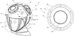
- FIG. 1is an isometric view of an exemplary embodiment of a helmet system.
- FIG. 2is an isometric view of the helmet system of FIG. 1 , with the outer helmet rendered transparently.
- FIG. 3is a top plan view of the helmet system of FIG. 1 , with the outer helmet rendered transparently.
- FIG. 4is a front elevation view of the helmet system of FIG. 1 , with the outer helmet rendered transparently.
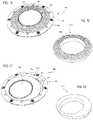
- FIG. 5is an exploded cutaway view of an exemplary orbital connector and resilient support.
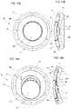
- FIG. 6is a detail view of the slip disc housing of the embodiment of FIG. 5 .
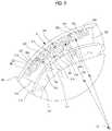
- FIG. 7is a detail view of the slip disc and post of the embodiment of FIG. 5 .
- FIG. 8is a cross-sectional side elevation view of the orbital connector of FIG. 5 , shown attached to a helmet system.
- FIG. 9is a partially exploded view illustrating multiple orbital connectors in various states of assembly with an inner helmet and an outer helmet.
- FIG. 10is a detail view of the spacer of FIG. 9 .
- FIG. 11is a cross-sectional side elevation view of the helmet system of FIG. 1 as shown on a wearer's head.
- FIG. 12is a bottom cross-sectional plan view of the helmet system of FIG. 1 .
- FIGS. 13 A and 13 Bare plan and cross-sectional side views, respectively, of an exemplary orbital spacer in a rest position.
- FIGS. 14 A and 14 Bare plan and cross-sectional side views, respectively, of the orbital spacer of FIGS. 13 A and 13 B in a deformed state during an impact load.
- FIG. 15illustrates another exemplary embodiment of an orbital spacer.
- FIG. 16is a detail view of the resilient barrier of the orbital spacer of FIG. 15 .
- FIG. 17illustrates the orbital spacer of FIG. 15 in a deformed state during an impact load.
- FIG. 18is a detail view of the resilient barrier of the orbital spacer of FIG. 15 in a deformed state during an impact load.
- FIG. 19is a plan view of another alternative embodiment of an orbital spacer.
- FIG. 20is a plan view of another alternative embodiment of an orbital spacer.
- FIG. 21is a detail view of alternative embodiment of a slip disc.
- FIG. 22is a detail view of another alternative embodiment of a slip disc.
- FIG. 23is a cutaway side view of another alternative embodiment of an orbital spacer.
- FIG. 24is a partially exploded view illustrating multiple orbital connectors in various states of assembly with an inner helmet and an outer helmet.
- FIG. 25is a cross-sectional side elevation view of another exemplary embodiment of a helmet system.
- FIG. 26is a cross-sectional side elevation view of another exemplary embodiment of a helmet system showing an alternative strap arrangement.
- FIG. 27is a cross-sectional side elevation view of another exemplary embodiment of a helmet system showing an alternative strap arrangement.
- FIG. 28is a cross-sectional side elevation view of another exemplary embodiment of a helmet system showing an alternative strap arrangement.
- FIG. 29is an isometric view of another exemplary embodiment of a helmet system showing an alternative strap arrangement, with the outer helmet rendered transparently.
- FIG. 30is a front isometric view of another exemplary embodiment of a helmet system showing an alternative padding arrangement.
- FIG. 31is a rear isometric view of the helmet system of FIG. 30 .
- FIG. 32is a top plan view of the helmet system of FIG. 30 .
- FIG. 33is cross-sectional side elevation view of the helmet of FIG. 30 , shown along line A-A in FIG. 32 .
- the embodiments of the invention described hereinrelate to protective headgear in the form of helmet systems.
- helmetis not intended to be limited, but is meant to encompass any headgear worn for protection during an activity in which an impact to the head may occur.
- embodiments described hereinrelate to helmet systems having an outer helmet, an inner helmet, and one or more orbital connectors that join the outer helmet to the inner helmet.
- the orbital connectorsallow the outer and inner helmets to displace relative to one another along a spherical path. Such displacement is believed to be effective to mitigate the impact force in some circumstances.
- Embodimentsmay be provided as complete helmet assemblies, or as components of such assemblies (e.g., replacement orbital connectors or orbital connectors adapted to work in other helmet systems).
- FIGS. 1 through 4illustrate an example of a helmet system 100 having an outer helmet 102 , an inner helmet 104 , and orbital connectors 106 joining the outer helmet 102 to the inner helmet 104 .
- the outer helmet 102preferably comprises a rigid shell structure formed from molded or layered plastics, composites, or the like. Exemplary materials include layers, weaves or random distributions of aramid (e.g., KEVLARTM) fibers, carbon fibers, glass fibers, and so on, that are rigidly bound together by a resin matrix. Other exemplary materials include plastics, such as polycarbonate, ABS (acrylonitrile butadiene styrene), and so on.
- the outer helmet 102 materialpreferably is relatively rigid, impact resistant, and lightweight.
- the exemplary outer helmet 102is formed with a main body 108 that is configured to surround the wearer's superior and posterior skull regions (i.e., the top and back of the head), an anterior opening 110 that is configured to be adjacent the wearer's eyes to permit viewing through the outer helmet 102 , and a chin guard 112 that extends from the main body 108 and below the anterior opening 110 and is configured to surround the wearer's chin.
- One or more air vents 114also may be provided, and a visor or facemask (not shown) may be installed over the anterior opening 110 . It will be understood that this configuration is exemplary, and other embodiments may lack the chin guard 112 , or have other shapes or features as generally known in helmet design.
- the inner helmet 104also preferably comprises a rigid outer shell 116 comprising materials such as those described above, and a pliable inner shell 118 comprising an impact-absorbing material such as those discussed below.
- the inner shell 118is configured to receive a portion of the wearer's head, and may include moldable or repositionable padding or the like to help with customizing the fit for the particular wearer.
- the outer shell 116 and inner shell 118are configured, via material selection and dimensioning of the parts, such that the inner shell 118 is more flexible than the outer shell 116 . Thus, loads on the inner helmet 104 will generally tend to deform the inner shell 118 to a greater degree than the outer shell 116 .
- the helmet system 100also may include a strap system for securing the helmet system 100 to the wearer's head.
- the shown strap systemcomprises an inner strap assembly for securing the inner helmet 104 to the wearer's head, and an outer strap assembly for securing the outer helmet 102 to the wearer's head.
- the inner strap assemblyincludes a first inner strap 120 attached to a first lateral side of the inner helmet 104 , and a second inner strap 122 attached to a second lateral side of the inner helmet 104 .
- Each inner strap 120 , 122may comprise multiple portions (i.e., multiple strap elements), such as shown in FIG. 2 .
- the outer strap assemblyincludes a first outer strap 124 attached to a first lateral side of the outer helmet 102 , and a second outer strap 126 attached to a second lateral side of the outer helmet 102 .
- Permanent or releasable connectors 128such as rivets, bolts, screws, snaps, or the like, may be used to secure the strap assemblies to the outer helmet 102 and inner helmet 104 .
- Each strap assemblymay include suitable clasps, snaps or other connectors to hold the strap assembly in place.
- the strap assembliesalso may be configured as chin straps (i.e., straps that are connected to each other to surround the front of the wearer's chin), or as under-chin straps (i.e., straps that are connected to each other at a location below the wearers chin).
- chin strapsi.e., straps that are connected to each other to surround the front of the wearer's chin
- under-chin strapsi.e., straps that are connected to each other at a location below the wearers chin.
- the outer strap assembly and inner strap assemblyare both configured as under-chin straps.
- Each strap assemblymay have a separate openable clasp to connect below the chin, or the straps 120 , 122 , 124 , 126 may be joined by a single openable clasp (e.g., straps 120 and 124 terminate at a first clasp element, and straps 122 and 126 terminate at a second clasp element, and the first and second clasp elements are connectable by snap connectors, latches, hooks or the like).
- a single openable claspe.g., straps 120 and 124 terminate at a first clasp element, and straps 122 and 126 terminate at a second clasp element, and the first and second clasp elements are connectable by snap connectors, latches, hooks or the like.
- one or both strap assembliesmay be omitted or replaced by different strap assemblies or holding systems.
- the orbital connectors 106are arranged to deflect and absorb impact loads that might come from a variety of directions.
- three orbital connectors 106may join the outer helmet 102 to the inner helmet 104 , and be configured with a front orbital connector 106 a at a medial, anterior position relative to the inner helmet 104 and the outer helmet 102 , and the two rear orbital connectors 106 b located at posterior and opposite lateral positions relative to the inner helmet 104 and the outer helmet 102 .
- This configurationis expected to be suitable for addressing impacts that occur in contact sports, such as American football, which might be coming from virtually any direction relative to the helmet system 100 .
- the use of three or more orbital connectors 106is preferred to ensure that at least one orbital connector 106 is at or near the point of impact. However, more than three orbital connectors 106 may be used, and may be preferable if the orbital connectors 106 are relatively small. Also, fewer than three orbital connectors 106 may be used, in which case additional padding might be positioned between the outer helmet 102 and inner helmet 104 to enhance protection against impacts coming from different directions.
- each orbital connector 106includes a slip disc housing 500 having a first face 502 , and a slip disc 504 having a second face 506 .
- the slip disc housing 500is mounted with the first face 502 facing towards the outer helmet 102
- the slip disc 504is mounted with the second face 506 facing towards the inner helmet 104 .
- the first face 502 and second face 506face each other and abut each other directly or via an intermediate layer of bearing material (e.g., lubricant, polytetrafluoroethylene sheet, or the like).
- the first face 502 and second face 506preferably are configured to slide relative to each other about a common spherical center SC.
- the first face 502 and second face 506may have matching radii of curvature, such that the second face 506 can slide smoothly along the first face 502 while maintaining contact with the first face 502 .
- An example of thisis illustrated in FIG.
- first face 502may have a first radius of curvature R 1 about a spherical center SC
- second face 506may have a second radius of curvature R 2 about the same spherical center SC, with the first radius of curvature R 1 and the second radius of curvature R 2 being equal or nearly equal (i.e., off by an amount attributable to normal manufacturing tolerances or an amount that does not affect performance as discussed below).
- the second face 506also has a smaller area than the first face 502 , as viewed radially with respect to its spherical center SC, which facilitates sliding of the second face 506 along the first face 502 .
- the first face 502surrounds an opening 508 through the slip disc housing 500 , and the slip disc 504 is attached to a post 510 that extends through the opening 508 .
- the post 510is dimensioned to move within the opening 508 , such that it does not fully inhibit the relative sliding between the first face 502 and second face 506 .
- the opening 508 and post 510have respective circular cross sections as viewed radially from the spherical center SC, with the opening 508 being larger than the post 510 to allow the post 510 to move in any direction from a starting central position until (assuming nothing else stops the movement) the post 510 contacts the edge of the opening 508 .
- the cross section of the opening 508may be selected to inhibit movement of the post 510 , and thus limit sliding movement between the first face 502 and the second face 506 .
- the opening 508could be shaped as a slot that allows relatively little movement of the post 510 in one direction, and relatively more movement of the post 510 in another direction.
- the opening 508is also dimensioned to be smaller than the second face 506 , such that the slip disc 504 cannot pass through the opening 508 .
- the orbital connector 106is assembled to the outer helmet 102 and inner helmet 104 by securing the slip disc housing 500 to the outer helmet 102 , and the slip disc 504 to the inner helmet 104 .
- the slip disc housing 500may be attached to the outer helmet 102 by fasteners 800 , such as rivets, bolts, screws (shown) or the like. If screws are used, the slip disc housing 500 may include threaded holes 512 formed by threading the material of the slip disc housing 500 or installing threaded inserts into the slip disc housing 500 .
- the slip disc housing 500has six threaded holes 512 , each formed by a threaded metal insert, surrounding the first face 502 .
- the slip disc 504is mounted to the inner helmet 104 in a similar manner. Specifically, the slip disc 504 may be attached to the post 510 and the post 510 may be secured to the inner helmet 104 by a fastener 800 such as those described above.
- the fastener 800is installed through an access hole 802 formed in the inner shell 118 , which allows loosening of the fastener 800 to reposition or service the orbital connector 106 .
- the inner shell 118may cover the fastener 800 , or the access holes 802 may be filled with additional impact attenuating material.
- the post 510may be integrally formed with the slip disc 504 (i.e., both formed from a unitary molded or machined part).
- the post 510comprises an elastomeric support 514 that is secured to the slip disc 504 , and a fastener interface 516 that is secured to the support 514 .
- the support 514provides a flexible connection between the slip disc 504 and the inner helmet 104 , which is expected to help attenuate impact loads transmitted to the post 510 , and help prevent the post 510 and slip disc 504 from being damaged by tensile loads during normal use.
- the support 514may comprise any suitable elastomeric material, such as styrene-butadiene, natural rubber, isoprene, neoprene, nitrile rubbers, or the like. As shown in FIG.
- the fastener interface 516may include one or more threaded holes that each receive a respective fastener 800 extending through the outer shell 116 of the inner helmet 104 .
- the fastener interface 516may comprise metal, durable plastic, or the like, and may include threaded inserts to receive the fasteners 800 .
- the second face 506abuts the first face 502 , and the first face 502 is located between the second face 506 and the inner helmet 104 to which it is attached by the post 510 .
- the second face 506is captured in place between the outer helmet 102 and the first face 502 , and is constrained to slide along and in contact with the first face 502 along a spherical path (i.e., tangentially to the spherical center SC, or stated another way, in a direction that is perpendicular to the first radius of curvature R 1 ).
- the post 510may connect the slip disc 504 to the inner helmet 104 with a tensile preload that pulls the second face 506 against the first face 502 , to help assure sliding contact throughout the range of movement.
- the orbital connector 106is configured to allow the outer helmet 102 to move along a generally spherical path relative to the inner helmet 104 . Such motion is expected to help divert impact loads to reduce the severity of impact experienced at the wearer's head. However, such movements preferably are restricted by absorb energy during the movement to reduce the severity of acceleration loads, and to prevent the outer helmet 102 from becoming improperly oriented relative to the inner helmet 104 (e.g., such that the outer helmet 102 impairs the wearer's vision).
- the orbital connector 106preferably includes a resilient barrier 518 located adjacent to the first face 502 and positioned to at least partially inhibit movement of the slip disc 504 relative to the slip disc housing 500 , and to return the orbital connector 106 to (or near) the starting position at the end of an impact.
- the orbital connector 106may include a resilient pad 520 that extends between the slip disc 504 and the outer helmet 102 to generate a friction force that holds the outer helmet 102 still relative to the inner helmet 104 until a force of sufficient magnitude is applied to the helmet system 100 .
- the resilient barrier 518may have an annular shape that fits into an annular space formed between a housing perimeter wall 522 and a disc perimeter wall 524 .
- the housing perimeter wall 522is formed as part of or otherwise attached to the slip disc housing 500 , and extends away from an outer perimeter of the first face 502 towards the outer helmet 102 .
- the disc perimeter wall 524is formed as part of or otherwise attached to the slip disc 504 , and extends away from the first face 502 towards the outer helmet 102 .
- the resilient barrier 518fits within the annular space, and preferably is in contact both the housing perimeter wall 522 and the disc perimeter wall 524 .
- some embodimentsmay include a gap between the resilient barrier 518 and the housing perimeter wall 522 or the disc perimeter wall 524 , in which case the gap will allow some degree of spherical sliding without impact attenuation until the resilient barrier 518 begins compression, and the slip disc 504 may not return to its starting position at the end of the impact.
- the resilient barrier 518may comprise any suitable impact absorbing material, such as those discussed below.
- the resilient barrier 518also may comprise a pressurized resilient gas bladder, an arrangement of springs or smaller segments of elastomeric material, and so on.
- the degree of resilience and impact absorbingcan be tailored by varying the shape of the resilient barrier 518 , as known in the art and as discussed below.
- the resilient pad 520is provided to hold the outer helmet 102 and inner helmet 104 in a fixed position until the helmet system 100 experiences a load of sufficient magnitude to overcome frictional contact between the resilient pad 520 , slip disc 504 and outer helmet 102 .
- the resilient pad 520may be connected to the slip disc 504 by adhesives, fasteners, or the like. Alternatively, or in addition, the resilient pad 520 may be captured in place in the spherical direction by a disc perimeter wall 524 if one is provided. The resilient pad 520 is slightly compressed between the slip disc 504 and the outer helmet 102 , thus generating a resilient restoring force against the slip disc 504 and outer helmet 102 .
- the resilient pad 520may be attached to the outer helmet 102 , such that the slip disc 504 slides relative to the resilient pad 520 when a sufficiently large impact force is applied.
- the resilient pad 520may comprise any suitable material, such as those discussed below.
- the resilient pad 520also may include layers of additional material or surface treatments at the interface with the outer helmet 102 or slip disc 504 to modify the coefficient of friction at the interface, and thereby regulate the magnitude of load required to initiate the spherical sliding movement.
- the resilient barrier 518 and resilient pad 520also may be functional to absorb impact loads in a direction perpendicular to the outer helmet 102 surface.
- an impact load F that strikes the outer helmet 102 as shown in FIG. 8can be attenuated by compression of the resilient barrier 518 and resilient pad 520 along the line of the force F.
- the helmet system 100may include supplemental impact attenuators between the orbital connector 106 and the inner helmet 104 .
- the helmet system 100may include a resilient support 526 positioned between the slip disc housing 500 and the inner helmet 104 .
- the shown exemplary resilient support 526has an annular base 528 that is positioned between the slip disc housing 500 and the inner helmet 104 , where it will compress under a load such as the shown impact force F.
- the resilient support 526also may include an outer wall 530 that surrounds the slip disc housing 500 to help absorb tangential forces, and to keep the resilient support 526 properly centered on the slip disc housing 500 .
- the resilient support 526surrounds the slip disc housing 500 and has a support opening 532 through which the post 510 passes.
- the opening 532is may be dimensioned to allow the post 510 to move a predetermined distance before contacting the opening 532 during sliding movement of the second face 506 relative to the first face 502 .
- the opening 532may be dimensioned to be contacted by the post 510 to provide additional impact attenuation at this interface.
- the exemplary resilient support 526is captured in place relative to the orbital connector 106 , and therefore it is not necessary to directly attach the resilient support 526 to any other part.
- the resilient support 526may be secured to the outer helmet 102 , inner helmet 104 and/or slip disc housing 500 by adhesives or fasteners.
- the resilient support 526may comprise other alternative structures, such as multiple separate parts that are positioned around the orbital connector 106 , or the like. Other alternatives and variations will be apparent to persons of ordinary skill in the art in view of the present disclosure.
- the resilient support 526comprises an impact-absorbing material, such as those discussed below.
- FIG. 9illustrates the assembly of multiple orbital connectors 106 onto the inner helmet 104 .
- a first orbital connector 106 ais attached by connecting the post 510 of the slip disc 504 to a first mounting point 900 on the inner helmet 104 using a fastener 800 , and by connecting the slip disc housing 500 to the outer helmet 102 using fasteners 800 (in FIG. 9 , the post 510 is preassembled with the inner helmet 104 and not visible, and only a portion of the outer helmet 102 is shown).
- the first orbital connector 106 ais secured between the outer helmet 102 and inner helmet 104 with a direct connection to each.
- the remaining orbital connectors 106 bare attached directly to the inner helmet 104 via their respective posts 510 .
- the remaining orbital connectors 106 bare indirectly attached to the outer helmet 102 via respective spacers 902 .
- the spacers 902are configured to bridge gaps that might otherwise exist between the outer helmet 102 and the inner helmet 104 . Such gaps may arise, for example, because the outer helmet 102 has a different shape than the inner helmet 104 .
- each spacer 902may comprise a plate 904 that fits over the respective slip disc housing 500 and has holes 906 for securing the spacer 902 to the slip disc housing 500 using a first set of fasteners 800 a .
- Mounting posts 908extend from the plate 904 towards the outer helmet 102 , and have respective threaded holes for receiving a second set of fasteners 800 b to secure the spacer 902 to the outer helmet 102 .
- Reinforcing ribs 910 and other structuresmay be provided to enhance the rigidity of the spacer 902 .
- the spacer 902also may include a layer of impact absorbing material (not shown) between the plate 904 and the outer helmet 102 .
- the entire spacer 902may comprise an impact absorbing material that is bonded at one end to the slip disc housing 500 and the other end to the outer helmet 102 .
- Other alternatives and variationswill be apparent to persons of ordinary skill in the art in view of the present disclosure.
- Spacers 902alternatively or additionally may be provided between an orbital connector 106 and the inner helmet 104 .
- the mounting points 900 for each orbital connector 106may have a different shape to hold the orbital connector 106 at a different distance from or orientation relative to the surrounding surface of the inner helmet 104 , as shown in FIGS. 9 and 12 .
- none of the orbital spacers 106may require a spacer 902 .
- each orbital connector 106may have a custom-shaped slip disc housing 500 that eliminates the need for a spacer 902 , or the gap between the outer helmet 102 and inner helmet 104 may be uniform at each orbital connector 106 location such that an identical orbital connector 106 may be used without any spacers 902 .
- the orbital spacers 106are preferably arranged such that they slide around a common spherical center SC. This principle is illustrated in FIGS. 11 and 12 .
- the three orbital spacers 106are all arranged with their respective first faces 502 having a common radius of curvature R 1 and a common spherical center.
- R 1radius of curvature
- R 2radius of curvature
- each orbital connector 106slides in unison with the remaining orbital connectors 106 , such that the outer helmet 102 moves uniformly relative to the inner helmet 104 .
- the outer helmet 102 and inner helmet 104are spherical in shape, this arrangement can be achieved simply by attaching identical orbital spacers 106 at various locations between the outer helmet 102 and inner helmet 104 .
- mounting posts 900 and spacers 902 of various shapesmay be used to help facilitate proper placement of the orbital connectors 106 at the desired locations.
- the foregoing concentric slidingis preferred because it is expected to allow relatively free movement of the outer helmet 102 relative to the inner helmet 104 , and allow control of that sliding movement using a selection of impact absorbing structures such as resilient barriers 518 and the like.
- this arrangementis not strictly necessary in all embodiments.
- embodiments having a single orbital connector 106will not have this arrangement.
- one or more of the orbital spacers 106may slide about a different spherical center SC, but binding can be avoided by allowing the outer helmet 102 or inner helmet 104 to flex to accommodate such independent movement. This may be accomplished by surrounding the interface between the orbital connector 106 and the outer helmet 102 with slots or flexible material that allows the orbital connector 106 to slide along a different spherical center SC than the other orbital connectors 106 .
- FIGS. 13 A and 13 Billustrate one embodiment of an orbital connector 106 .
- the resilient barrier 518fits tightly between the slip disc housing 500 and slip disc 504 (more specifically, between the housing perimeter wall 522 and the disc perimeter wall 524 ).
- the slip disc 504cannot move relative to the slip disc housing 500 without compressing at least a portion of the resilient barrier 518 .
- This configurationis expected to provide uniform impact attenuation in all sliding directions.
- FIGS. 14 A and 14 Bshow the embodiment of FIGS. 13 A and 13 B during an impact loading.
- the resilient barrier 518deforms to allow the slip disc 504 to spherically slide relative to the slip disc housing 500 .
- the resilient barrier 518may distort as shown, by elongating to form a gap 1400 between the disc perimeter wall 524 and the resilient barrier 518 .
- the resilient barrier 518preferably exerts a resilient force to reposition the slip disc 504 at the starting location shown in FIG. 13 A .
- FIGS. 15 and 16illustrate another alternative orbital connector 106 .
- the orbital connector 106has an resilient barrier 518 having a plurality of holes 1500 .
- the holes 1500reduce the resilience of the resilient barrier 518 , thereby allowing the resilient barrier 518 to compress more easily.
- the holes 1500are provided in a uniform pattern of concentric rings, to provide uniform impact attenuation in all directions.
- the holes 1500alternatively may be provided in a non-uniform pattern to provide different degrees of impact attenuation depending on the impact direction.
- FIGS. 17 and 18show the embodiment of FIGS. 15 and 16 during an impact loading, with the holes 1500 omitted for simplicity of illustration.
- the slip disc 504spherically slides relative to the slip disc housing 500 , and the resilient barrier 518 moves with the slip disc 504 , thus forming a gap 1700 between the resilient barrier 518 and the housing perimeter wall 522 .
- the resilient barrier 518exerts a resilient force to reposition the slip disc 504 at the starting position shown in FIG. 15 .
- FIG. 19shows another exemplary orbital connector 106 having two variations on the orbital connectors 106 shown in FIGS. 13 A through 18 .
- the resilient barrier 518is formed with radial arms 1900 instead of a solid (or perforated) block of material. This allows the resilience of the resilient barrier 518 to be modified depending on the angle of impact, such as by changing the spacing or thickness of the arms 1900 .
- the arms 1900have different lengths extending from a central ring 1902 , to thereby locate the slip disc 504 at a predetermined non-centered location relative to the slip disc housing 500 . This may be useful to help locate the orbital connector 106 at the desired location relative to the outer helmet 102 and inner helmet 104 , and to adjust user fit.
- resilient barrier 518may have other modifications to regulate the resilience of the resilient barrier 518 , such as regions of different depth (i.e., thickness along the radius of the spherical center SC), cutouts of various shape, or the like.
- FIG. 20illustrates another example of an orbital connector 106 .
- the housing perimeter wall 522 and the disc perimeter wall 524are both non-circular.
- the resilient barrier 518is provided as a plurality of discs of material that may or may not be connected to each other.
- one of the housing perimeter wall 522 and the disc perimeter wall 524may be circular and the other may be non-circular, or they could have other different geometric shapes.
- the orbital connector 106may have a variety of different shapes and configurations, while still providing a spherical sliding function to help redirect and attenuate impact loads.
- spherical slidingis provided at an interface between the first face 502 and second face 506 , in which the first face 502 and second face 506 both comprise continuous hemispherical surfaces (i.e., surfaces that extend continuously at a fixed distance from the spherical center SC.
- continuous hemispherical surfacesis not strictly required.
- first face 502 and second face 506may comprise a discontinuous surface formed by discrete component faces that contact with the other of the first face 502 and second face 506 .
- FIG. 21An example of this construction is shown in FIG. 21 .
- the second face 506is formed by three or more discrete second face 506 segments that protrude from a base surface 2000 towards and into contact with the first face 502 .
- the second face 506 segmentshave portions that are arranged at a common radius from a spherical center, and positioned such that they remain in contact with the second face 506 throughout the range of motion of the slip disc 504 .
- each face segmentmay comprise a small concave hemispherical surface that is concentric with the spherical center SC, a flat planar surface, a convex spherical surface, or any other shape that allows sliding tangentially to the spherical center SC.
- the slip disc 504obtains the desired spherical sliding against the slip disc housing 500 by use of a discontinuous surface.
- FIG. 22shows another alternative example of a second face 506 .
- the second face 506is formed as a circular rib that protrudes from a base surface 2000 of the slip disc 504 .
- Other embodimentsmay have surfaces having different shapes (e.g., cross shapes, square shapes, etc.). These and other variations can also be made to the first face 502 .
- the first face 502 and second face 506should be configured such that they do not have gaps or discontinuities that would interrupt the spherical sliding motion between the slip disc housing 500 and the slip disc 504 .
- FIG. 23Another alternative embodiment is illustrated in FIG. 23 .
- This embodimentis generally the same as the embodiment shown in FIG. 8 , but the slip disc housing 500 is mounted to the inner helmet 104 , and the slip disc 504 is mounted to the outer helmet 102 .
- the partshave the reverse orientation, but otherwise operate in the same manner as previously described.
- FIG. 24shows another example of a helmet system 100 in partial exploded view.
- the resilient barrier 518has holes to reduce deflection resistance, such as described in relation to FIGS. 15 and 16 .
- the resilient supports 526are provided as relatively simple pads that may be attached directly to the inner helmet 104 by adhesives or the like.
- FIG. 25shows additional alternative features, which may be used separately or together, or in combination with the other embodiments described herein.
- the helmet system 100comprises an outer helmet 102 and inner helmet 104 that are connected by a single orbital connector 106 .
- the orbital connector 106preferably is located at a likely location for impacts.
- the orbital connector 106is located at the anterior skull region between the forehead and the top of the head, where it is intended to mitigate impacts caused by falling forward.
- Such a configurationmay be useful in bicycle helmets, skiing helmets, and other helmets intended for use in non-contact sports where impacts from the rear are less likely.
- the orbital connector 106may be located on a lateral side of the skull region, as may be desirable to deflect impacts from oncoming objects such as baseballs and cricket balls.
- the helmet system 100 of FIG. 25also incorporates conventional impact padding 2500 to hold the outer helmet 102 and inner helmet 104 in proper position.
- This examplealso has an outer helmet 102 that lacks a chin guard.
- Other alternatives and variationswill be apparent to persons of ordinary skill in the art in view of the present disclosure.
- the helmet system 100may include one or more strap assemblies, such as under-shin straps and chin straps, that are configured to hold the helmet system 100 to the wearer's head.
- FIGS. 26 - 29show various alternative arrangements of strap assemblies.
- FIG. 26shows a helmet system 100 having an under-chin strap 2600 that wraps around below the wearer's chin 2602 , and a chin strap 2604 that wraps around the front of the wearer's chin 2602 .
- the under-chin strap 2600is connected, on each lateral side of the helmet system 100 , to the inner helmet 104 via an inner strap assembly.
- the inner strap assemblyincludes a front inner strap 122 a and a rear inner strap 122 b on each side of the helmet system 100 .
- the inner strap assemblyis connected to the inner helmet 104 by a first set of connectors 128 a .
- the chin strap 2604is connected, on each lateral side of the helmet system 100 , to the outer helmet 102 via an outer strap assembly.
- the outer strap assemblyincludes a front outer strap 124 a and a rear outer strap 124 b on each side of the helmet system 100 .
- the outer straps 124 a , 124 bare connected to the outer helmet 102 by a second set of connectors 128 b .
- the strap assembliesmay have any suitable construction, such as nylon webbing straps that are connected by sliding adjusters or snaps, openable clasps or hooks, and so on.
- FIG. 27is the same as the embodiment of FIG. 26 , except that the under-chin strap 2600 is connected via the outer strap assembly to the outer helmet 102 , and the chin strap 2604 is connected via the inner strap assembly to the inner helmet 104 .
- FIG. 28the helmet system 100 has chin strap 2604 , but no under-chin strap 2600 .
- the outer strap assembly and the inner strap assemblyare all connected to the chin strap 2604 .
- FIG. 28also shows another alternative configuration, in which the inner strap assembly comprises a single inner strap 122 on each side of the helmet system 100 .
- FIG. 29shows another exemplary embodiment of a helmet system 100 .
- the inner strap assemblyis formed as an under-chin strap having a bifurcated and Y-shaped inner strap 122 that joins a single strap under the chin, but splits on each side of the helmet system 100 to connect to the inner helmet 104 at two locations.
- This examplealso shows the outer strap assembly being attached to connectors 128 located on the outer surface of the outer helmet 102 , to thereby allow rapid connection of the outer strap assembly.
- any strap forming a strap assemblymay comprise a single webbing or band of material (e.g., the single inner strap 122 in FIG. 28 ), or it may comprise multiple webbings or bands, or webbings or bands that are bifurcated or otherwise divided into multiple components.
- the various parts of the helmet system 100 and orbital connector 106may be made from any suitable materials, such as plastic, metal, composites, elastomers, or the like.
- suitable materialssuch as plastic, metal, composites, elastomers, or the like.
- the selection of suitable materialswill be possible to persons of ordinary skill in the art, without undue experimentation, upon practicing embodiments of the invention.
- FIGS. 30 to 33an example of a helmet system 100 configured for use in a contact sport, such as American Football, is described with a selection of exemplary materials and other properties that may be suitable in some embodiments.
- the exemplary helmet system 100 of FIGS. 30 to 33comprises an outer helmet 102 that is connected to an inner helmet 104 by three orbital connectors 106 , such as those described herein.
- the outer helmet 102comprises a shell of rigid material such as polycarbonate plastic, a composite formed by high-strength fibers (e.g., aramid) and a resin matrix, or the like.
- Each orbital connector 106has a slip disc housing 500 mounted to the outer helmet 102 , and a slip disc 504 mounted to the inner helmet 104 .
- Each orbital connector 106includes a resilient barrier 518 and a resilient pad 520 , and a resilient support 526 is positioned between each orbital connector 106 and the inner helmet 104 .
- the resilient supports 526may be captured in place, adhered to the inner helmet 104 , or adhered to the orbital spacer 106 (e.g., attached to the slip disc housing 500 ).
- the helmet system 100also includes a plurality of inserts 3000 comprising impact-attenuating material to provide further impact absorption.
- the inserts 3000may be connected to one or both of the outer helmet 102 and the inner helmet 104 , but preferably are not connected in such a manner to inhibit the desired degree of movement of the orbital spacers 106 .
- the inserts 3000also preferably are not formed of a material that is rigid enough to impair the operation of the orbital spacers 106 .
- the resilient barrier 518 , resilient pad 520 , resilient support 526 and spacers 3000may comprise any suitable impact attenuating material, such as synthetic or natural rubbers, polyurethanes, and the like.
- the materialmay be provided in block form, as an open-cell or closed-cell foam, as a high-density foam or low-density foam, or in any other suitable form.
- Exemplary materialsinclude, but are not limited to: polyvinyl nitrile foam (PVN), Poly(vinyl formal) (PVF) foam, neoprene and neoprene blends, high-density polyurethane, expanded polystyrene and so on.
- the resilient barriers 518are selected to allow at least about 0.5 inches of relative movement between the outer helmet and the inner helmet in a direction tangential to the spherical center SC defined by the orbital spacers 106 .
- the resilient barriers 518may be configured to allow the slip disc 504 and slip disc housing 500 of each orbital spacer 106 to move at least about 0.5 inches relative to each other in a direction tangential to the spherical center SC defined by the orbital spacer 106 .
- Other embodimentsmay allow different degrees of motion, and may be tailored to particular sports or activities, or to individual users.
- the helmet system 100may be assembled using any suitable method.
- the helmet system 100is assembled by: (1) assembling each slip disc 504 , post 510 , resilient barrier 518 and slip disc housing 500 into an orbital connector 106 ; (2) attaching each orbital connector 106 to the inside of the outer helmet 102 using screws (e.g., six #8, 32 thread per inch screws) that pass through the outer helmet 102 and into the slip disc housing 500 ; and then (3) attaching the inner helmet 104 to each orbital connector 106 using screws (e.g., a single #10, 24 thread per inch screw) that pass through the inner helmet 104 and into the post 510 .
- Other assembly methodsmay be used in other embodiments.
Landscapes
- Helmets And Other Head Coverings (AREA)
Abstract
Description
Claims (18)
Priority Applications (3)
| Application Number | Priority Date | Filing Date | Title |
|---|---|---|---|
| US16/817,223US11540577B2 (en) | 2020-03-12 | 2020-03-12 | Helmet system |
| US16/861,792US11540578B2 (en) | 2020-03-12 | 2020-04-29 | Helmet system |
| PCT/US2021/021807WO2021183708A1 (en) | 2020-03-12 | 2021-03-11 | Helmet system |
Applications Claiming Priority (1)
| Application Number | Priority Date | Filing Date | Title |
|---|---|---|---|
| US16/817,223US11540577B2 (en) | 2020-03-12 | 2020-03-12 | Helmet system |
Related Child Applications (1)
| Application Number | Title | Priority Date | Filing Date |
|---|---|---|---|
| US16/861,792Continuation-In-PartUS11540578B2 (en) | 2020-03-12 | 2020-04-29 | Helmet system |
Publications (2)
| Publication Number | Publication Date |
|---|---|
| US20210282488A1 US20210282488A1 (en) | 2021-09-16 |
| US11540577B2true US11540577B2 (en) | 2023-01-03 |
Family
ID=77664030
Family Applications (1)
| Application Number | Title | Priority Date | Filing Date |
|---|---|---|---|
| US16/817,223Active2040-11-02US11540577B2 (en) | 2020-03-12 | 2020-03-12 | Helmet system |
Country Status (1)
| Country | Link |
|---|---|
| US (1) | US11540577B2 (en) |
Families Citing this family (1)
| Publication number | Priority date | Publication date | Assignee | Title |
|---|---|---|---|---|
| WO2022093675A1 (en)* | 2020-10-26 | 2022-05-05 | Baptist Health South Florida, Inc. | Dual-shell helmet |
Citations (303)
| Publication number | Priority date | Publication date | Assignee | Title |
|---|---|---|---|---|
| US1522952A (en) | 1922-11-20 | 1925-01-13 | P Goldsmith Sons Company | Football helmet |
| US1602727A (en) | 1924-05-29 | 1926-10-12 | Wilson Western Sporting Goods | Helmet or head guard |
| DE508419C (en) | 1930-09-26 | Robert Larsen | Insert for headgear, especially for steel helmets | |
| US2250725A (en) | 1939-12-01 | 1941-07-29 | Willard G Ranson | Brake mechanism |
| US2420522A (en) | 1942-03-09 | 1947-05-13 | Daly Le Grand | Method of making articles from plastic treated materials |
| US2455797A (en) | 1946-07-06 | 1948-12-07 | Mine Safety Appliances Co | Helmet |
| US2532442A (en) | 1942-03-09 | 1950-12-05 | Daly Le Grand | Molded article |
| US2610332A (en) | 1950-12-22 | 1952-09-16 | John J Field | Combination crib and playpen |
| US2753561A (en) | 1955-03-07 | 1956-07-10 | Mauro Eugene | Head protector |
| US2969547A (en) | 1958-12-17 | 1961-01-31 | Edward R Dye | Protective head covering |
| US3067427A (en) | 1960-08-26 | 1962-12-11 | Sr Howard W Mcclintock | Face guards for batters' helmets |
| US3153792A (en) | 1963-07-09 | 1964-10-27 | Michael T Marietta | Two part detachable liner for safety helmets |
| US3166761A (en) | 1961-09-27 | 1965-01-26 | Brunswick Corp | Chin strap construction for football helmets |
| US3197784A (en) | 1962-09-04 | 1965-08-03 | Carlisle Res And Dev Corp | Segmented helmet |
| US3208080A (en) | 1964-03-30 | 1965-09-28 | Hirsch Arthur Ernest | Protective helmet |
| US3290693A (en) | 1964-12-14 | 1966-12-13 | American Baseball Cap Inc | Baseball batter's helmet |
| US3315273A (en) | 1965-06-01 | 1967-04-25 | Ethan C Bullard | Safety cap |
| US3500473A (en) | 1967-12-14 | 1970-03-17 | Wolverine World Wide Inc | Safety headgear assembly |
| US3529306A (en) | 1968-12-17 | 1970-09-22 | Edward P Thorne | Equalizer device |
| US3568210A (en) | 1968-10-10 | 1971-03-09 | Michael T Marietta | Protective headgear |
| US3577562A (en) | 1969-10-01 | 1971-05-04 | Mike C Holt | Athletes{3 {0 protective helmet particularly football |
| US3582990A (en) | 1969-10-07 | 1971-06-08 | Gentex Corp | Ballistic cover for protective helmet |
| US3609764A (en) | 1969-03-20 | 1971-10-05 | Riddell | Energy absorbing and sizing means for helmets |
| US3665514A (en) | 1970-09-22 | 1972-05-30 | Us Army | Low profile size adjustable protective helmet |
| DE2210205B1 (en) | 1972-03-03 | 1973-03-22 | Fa. Hans Römer, 7910 Neu -Ulm | INTERIOR FOR PROTECTIVE HELMETS |
| US3783450A (en) | 1973-02-05 | 1974-01-08 | Connor W O | Hockey helmet |
| US3845389A (en) | 1973-09-26 | 1974-10-29 | Int Signal & Control Corp | Helmet transceiver assembly for a firemen{40 s helmet assembly or the like |
| US3897596A (en) | 1974-08-26 | 1975-08-05 | Gentex Corp | Protective helmet |
| US3906546A (en) | 1973-04-16 | 1975-09-23 | Elwyn R Gooding | Hand gun bullet proof protective headgear |
| US3994023A (en) | 1975-10-23 | 1976-11-30 | Gentex Corporation | Simplified protective helmet assembly |
| US3994020A (en) | 1975-06-05 | 1976-11-30 | The Kendall Company | Protective helmet with liner means |
| US3994021A (en) | 1975-06-05 | 1976-11-30 | The Kendall Company | Protective helmet |
| US4233687A (en) | 1978-08-14 | 1980-11-18 | Lancellotti William E | Sports helmet with face mask |
| US4282610A (en) | 1978-01-16 | 1981-08-11 | The Kendall Company | Protective headgear |
| USD267287S (en) | 1980-09-11 | 1982-12-21 | The Regents Of The University Of Michigan | Pneumatic liner for protective headgear |
| US4375108A (en) | 1981-01-28 | 1983-03-01 | The Regents Of The University Of Michigan | Energy-absorbing insert for protective headgear |
| US4404690A (en) | 1981-08-21 | 1983-09-20 | Amer Sport International Inc. | Hockey helmet |
| US4432099A (en) | 1982-07-09 | 1984-02-21 | Gentex Corporation | Individually fitted helmet liner |
| US4484364A (en) | 1980-09-08 | 1984-11-27 | A-T-O Inc. | Shock attenuation system for headgear |
| US4596056A (en) | 1983-02-22 | 1986-06-24 | Gentex Corporation | Helmet shell fabric layer and method of making the same |
| US4627114A (en) | 1984-08-23 | 1986-12-09 | Figgie International, Inc. | Shock attenuation structure |
| EP0217996A1 (en) | 1985-10-11 | 1987-04-15 | Ab Akta Barnsäkerhet | Protective recreational helmet |
| US4729132A (en) | 1986-11-03 | 1988-03-08 | Fierro Mark F | Sports helmet |
| DE8804821U1 (en) | 1988-04-13 | 1988-06-01 | Peter Küpper "Codeba" GmbH & Co, 5600 Wuppertal | Headgear such as helmet, cap, hat or similar, especially for riders |
| US4821341A (en) | 1987-05-13 | 1989-04-18 | Baptiste Trevor I | Sun-visor and headpiece combination and package therefor |
| US4833735A (en) | 1987-07-01 | 1989-05-30 | Gentex Corporation | Helmet suspension with integrated crown straps and headband |
| US4856119A (en) | 1987-08-01 | 1989-08-15 | Romer Gmbh | Helmet with three-point chin strap |
| US4903381A (en) | 1988-01-28 | 1990-02-27 | Foehl Artur | Fastener mechanism for the chin strap of a helmet |
| US4996724A (en) | 1989-10-20 | 1991-03-05 | Innova-Dex Sports, Inc. | Protective rim configuration for hard-shelled safety helmet |
| US5012533A (en) | 1989-04-04 | 1991-05-07 | K. W. Hochschorner Gmbh | Helmet |
| US5014365A (en) | 1989-01-23 | 1991-05-14 | Maxpro Helmets, Inc. | Gas-fitted protective helmet |
| US5035009A (en) | 1990-09-27 | 1991-07-30 | Riddell, Inc. | Protective helmet and liner |
| US5088129A (en) | 1990-08-20 | 1992-02-18 | Shoei Kako Kabushiki Kaisha | Helmet |
| US5088126A (en) | 1990-04-26 | 1992-02-18 | Mathis Richard M | Disposable liner for protective head coverings |
| US5119505A (en) | 1989-08-11 | 1992-06-02 | Andre Tisseront | Protective helmet with removable protective lining for cushioning radio circuitry |
| US5119514A (en) | 1990-10-05 | 1992-06-09 | Woehl William L | Ear shield cap |
| US5173970A (en) | 1992-01-15 | 1992-12-29 | Roy Shifrin | Combined visored cap type protective helmet and pouch for bicyclists or the like |
| US5177815A (en) | 1990-04-09 | 1993-01-12 | Andujar Edward M | Protective headgear |
| US5226180A (en) | 1991-12-02 | 1993-07-13 | Leach Robert E | Protective cap for golfers |
| US5249347A (en) | 1992-01-30 | 1993-10-05 | Canstar Sports Group Inc. | Face mask for sports gear |
| US5269026A (en) | 1992-06-19 | 1993-12-14 | Mcmanus Eugene E | Adjustable cap with safety liner |
| US5269025A (en) | 1988-09-26 | 1993-12-14 | Bell Bicycles, Inc. | Reinforced expanded plastic helmet construction |
| US5271103A (en) | 1992-10-19 | 1993-12-21 | Darnell Eric A | Impact protective headgear |
| US5289591A (en) | 1991-10-25 | 1994-03-01 | Andersen Kelvin D | Hard ball golf hat |
| US5298208A (en) | 1991-11-01 | 1994-03-29 | Athletic Helmet, Inc. | Method for molding a protective helmet |
| US5337420A (en) | 1992-11-03 | 1994-08-16 | Haysom Elbert M | Method and apparatus for mounting and locating a helmet comfortably on the head of a person, and combination resulting therefrom |
| EP0623292A1 (en) | 1993-03-26 | 1994-11-09 | Gec-Marconi Limited | Helmets |
| USD364496S (en) | 1994-09-26 | 1995-11-28 | Clifford Lejuez | Shock absorbing insert for a cap |
| US5515546A (en) | 1994-09-14 | 1996-05-14 | Shifrin; Roy | Foldable padded helmet |
| DE29605144U1 (en) | 1996-03-20 | 1996-05-15 | Burger, Hans-Joachim, 92245 Kümmersbruck | Fitting hard hat |
| US5517691A (en) | 1993-04-02 | 1996-05-21 | Lion Apparel, Inc. | Protective helmet |
| US5519895A (en) | 1993-04-28 | 1996-05-28 | Barnes, Jr.; Montie M. | Cap for sports helmet |
| US5587239A (en) | 1993-06-29 | 1996-12-24 | Kureha Kagaku Kogyo Kabushiki | Ball-like structures and contacting materials for wastewater-treatment |
| US5598588A (en) | 1995-09-05 | 1997-02-04 | Simmons International Korea Ltd. | Cycling helmet |
| US5603117A (en) | 1995-09-13 | 1997-02-18 | The United States Of America As Represented By The Secretary Of The Army | Protective helmet assembly |
| US5625901A (en) | 1995-10-04 | 1997-05-06 | Healy; James W. | Ventilating hat band |
| US5661854A (en) | 1994-09-01 | 1997-09-02 | March, Ii; Richard W. | Flexible helmet |
| US5666670A (en) | 1994-08-01 | 1997-09-16 | Pamela S. Ryan | Protective helmet |
| US5687426A (en) | 1993-02-25 | 1997-11-18 | Elasto Form | Bicycle helmet |
| US5713082A (en) | 1996-03-13 | 1998-02-03 | A.V.E. | Sports helmet |
| US5752298A (en) | 1996-10-15 | 1998-05-19 | Down East, Inc. | Earcup tension adjustment strap assembly |
| CH689008A5 (en) | 1997-08-12 | 1998-07-31 | Renato Pellegrini | Head protector for small children |
| US5815847A (en) | 1997-06-23 | 1998-10-06 | Ampac Enterprises, Inc. | One size fits all baseball batter's helmet |
| WO1998046095A2 (en) | 1997-04-11 | 1998-10-22 | Bell Sports, Inc. | Safety helmet |
| US5887289A (en) | 1997-06-19 | 1999-03-30 | Theoret; Normand | Safety cap with removable fabric cover |
| USD410768S (en) | 1998-05-28 | 1999-06-08 | Hirsh Donald W | Soccer helmet |
| US5913412A (en) | 1994-03-22 | 1999-06-22 | So Services Ag | Protective helmet |
| US5915538A (en) | 1995-01-09 | 1999-06-29 | Gallet S.A. | Protective helmet and chin strap attachment device therefor |
| US5915537A (en) | 1997-01-09 | 1999-06-29 | Red Corp. | Helmet |
| US5987649A (en) | 1998-03-06 | 1999-11-23 | Robertson; Richard K. | Cap insert |
| US5996126A (en) | 1998-07-22 | 1999-12-07 | Cairns & Brother Inc. | Crown pad and head-protective helmet |
| GB2342845A (en) | 1998-08-28 | 2000-04-26 | Jsp Ltd | Improvements relating to safety caps |
| US6073272A (en) | 1998-01-07 | 2000-06-13 | Red Corp. | Helmet with ear protection and a hearing enhancement feature |
| US6073271A (en) | 1999-02-09 | 2000-06-13 | Adams Usa, Inc. | Football helmet with inflatable liner |
| WO2000035307A1 (en) | 1998-12-11 | 2000-06-22 | Cunningham, Gary, Richard | Head wear and method of forming same |
| US6081929A (en) | 1998-12-04 | 2000-07-04 | Bell Sports, Inc. | Impact protection helmet with air extraction |
| US6093468A (en) | 1997-03-14 | 2000-07-25 | The Procter & Gamble Company | Flexible lightweight protective pad with energy absorbing inserts |
| US6094750A (en) | 1999-03-31 | 2000-08-01 | Lung Huei Safety Helmet Co., Ltd. | Modified safety helmet heat sink |
| US6108824A (en) | 1998-08-12 | 2000-08-29 | Sport Maska Inc. | Helmet adjustment mechanism with quick release |
| USD431329S (en) | 1999-03-30 | 2000-09-26 | Asics Corporation | Knee pad cushion |
| US6138283A (en) | 1998-03-10 | 2000-10-31 | Kress; James R. | Protective helmet with medical emergency removal feature |
| US6154889A (en) | 1998-02-20 | 2000-12-05 | Team Wendy, Llc | Protective helmet |
| JP2001073218A (en) | 1999-08-27 | 2001-03-21 | Takenaka Komuten Co Ltd | Head-protection tool |
| US6219850B1 (en) | 1999-06-04 | 2001-04-24 | Lexington Safety Products, Inc. | Helmet |
| US6240571B1 (en) | 1999-11-09 | 2001-06-05 | Riddell, Inc. | Protective helmet with adjustable sizes |
| US6256799B1 (en) | 1999-08-10 | 2001-07-10 | Mcglasson Shirley J. | Helmet covers |
| US6256798B1 (en) | 1997-05-14 | 2001-07-10 | Heinz Egolf | Helmet with adjustable safety strap |
| US6282724B1 (en) | 2001-02-21 | 2001-09-04 | Carl Joel Abraham | Apparatus for enhancing absorption and dissipation of impact forces for all helmets and protective equipment |
| EP1136007A2 (en) | 2000-03-15 | 2001-09-26 | Hermann Wolfgang Schwan | Protective cap |
| US6298497B1 (en) | 1996-11-29 | 2001-10-09 | Bauer Nike Hockey, Inc. | Hockey helmet with self-adjusting padding |
| US6301719B1 (en) | 2000-09-28 | 2001-10-16 | Itech Sport Products Inc. | Helmet face protector attachment system |
| US6324700B1 (en) | 1999-11-24 | 2001-12-04 | Bauer Nike Hockey Inc. | Adjustable protective helmet |
| US20020000004A1 (en) | 1999-02-25 | 2002-01-03 | Wise Layton A. | Suspension for protective headgear |
| US20020002730A1 (en) | 1998-09-03 | 2002-01-10 | Mike Dennis | Body- contact cushioning interface structure and method |
| US20020007508A1 (en) | 2000-04-26 | 2002-01-24 | Grepper Theo H. | Adjustable helmet |
| US6343385B1 (en) | 1996-12-02 | 2002-02-05 | Jeffrey P. Katz | Impact absorbing protective apparatus for the frontal, temporal and occipital basilar skull |
| US6349416B1 (en) | 1999-07-23 | 2002-02-26 | Soccordocs, Inc. | Headguard-protective sports headband |
| US20020023290A1 (en) | 1998-09-25 | 2002-02-28 | Sportscope Inc. | Insert-molded helmet |
| US6360376B1 (en) | 1997-04-10 | 2002-03-26 | Plum Enterprises, Inc. | Protective hat |
| US20020035748A1 (en) | 2000-09-28 | 2002-03-28 | Bertrand Racine | Protective helmet with adjustable padding |
| US6367090B1 (en) | 2001-03-07 | 2002-04-09 | Sang Jun Im | Reversible two color protective headgear and blank therefor |
| US6370697B1 (en) | 2000-01-13 | 2002-04-16 | Cool Hat, Inc. | Device and method of allowing air to circulate into and out of a hat |
| US6374423B1 (en) | 2001-05-18 | 2002-04-23 | Kris A. Anderson | Sports helmet with full flexible brim |
| US6381759B1 (en) | 1996-12-02 | 2002-05-07 | Jeffrey P. Katz | Impact absorbing protective apparatus for the frontal, temporal and occipital basilar skull |
| US6389607B1 (en) | 2000-09-26 | 2002-05-21 | James C. Wood | Soft foam sport helmet |
| US6418564B1 (en) | 2001-05-11 | 2002-07-16 | Patrick Sheridan | Two piece helmet with optional airbag |
| US6425143B1 (en) | 2001-02-08 | 2002-07-30 | Arctic Cat, Inc. | Helmet with ventilation for fog management and respiration |
| US20020114959A1 (en) | 2000-12-13 | 2002-08-22 | Soonkun Kang | Sporting goods having a ceramer coating |
| US6442765B1 (en) | 1999-03-27 | 2002-09-03 | Vincent Fallon | Safety helmet |
| US6453476B1 (en) | 2000-09-27 | 2002-09-24 | Team Wendy, Llc | Protective helmet |
| US6457210B1 (en) | 1998-04-23 | 2002-10-01 | Builmatel Co., Ltd. | Buckle and band with this buckle |
| US6499139B1 (en) | 2002-01-07 | 2002-12-31 | 13-31-Sport, Inc. | Face guard |
| WO2003005843A1 (en) | 2001-07-13 | 2003-01-23 | Scott International Limited | Protective headgear |
| US6519781B1 (en) | 2001-09-07 | 2003-02-18 | Salomon S.A. | Energy absorbing protective device that protects areas of articulation |
| US20030070209A1 (en) | 2001-10-16 | 2003-04-17 | Thomas Falone | Athletic clothing with sting reduction padding |
| US6550071B2 (en) | 2001-09-04 | 2003-04-22 | Louis Garneau Sports Inc. | Cyclist helmet with reinforcing hoops |
| USD479020S1 (en) | 2003-01-14 | 2003-08-26 | Virgil D. Heinrich | Safety insert for cap |
| US20030167558A1 (en) | 2002-03-05 | 2003-09-11 | Lester Broersma | Full coverage protective head gear |
| US6694529B1 (en) | 2002-11-25 | 2004-02-24 | Tzu Tao Chiu | Helmet structure |
| US20040034903A1 (en) | 2000-10-06 | 2004-02-26 | Blair Mary Lynne | Protective sports hat insert device |
| WO2004016122A1 (en) | 2002-08-16 | 2004-02-26 | Di Giovanni, Frances, Grace | Protective garment |
| US20040040073A1 (en) | 2002-08-30 | 2004-03-04 | David Morrow | Protective sport helmet |
| US20040107482A1 (en) | 2001-08-07 | 2004-06-10 | Brooke Picotte | Head protector for infants, small children, senior citizens, adults or physically disabled individuals |
| US6751808B2 (en) | 2002-09-09 | 2004-06-22 | Ione G. Puchalski | Sports helmet having impact absorbing crumple or shear zone |
| US6760927B2 (en) | 2000-01-28 | 2004-07-13 | Louis Guay | Device for adjusting head band for protective helmet |
| US20040172739A1 (en) | 2001-09-25 | 2004-09-09 | Bertrand Racine | Locking device for adjustable helmets |
| US20040226077A1 (en) | 2003-05-14 | 2004-11-18 | Toth Gregory T. | Systems and methods for providing a headgear cooling liner |
| DE202004012916U1 (en) | 2004-08-18 | 2004-12-30 | Sinotec Sicherheitssysteme Gmbh | Plastic cap protects head of wearer against knocks and blows of not too serious nature, has wall thickness of approximately 1mm and is matched in shape to largest skull |
| US20050034223A1 (en) | 2003-08-15 | 2005-02-17 | Jacques Durocher | Hockey helmet comprising a lateral adjustment mechanism |
| US20050060908A1 (en) | 2001-08-27 | 2005-03-24 | Vito Robert A. | Vibration dampening material and method of making same |
| WO2005027671A1 (en) | 2003-09-19 | 2005-03-31 | Sancheong Co., Ltd. | Safety helmet |
| US6883181B2 (en) | 2003-07-08 | 2005-04-26 | Gentex Corporation | Adjustable padset for protective helmet |
| US20050166302A1 (en) | 1998-09-03 | 2005-08-04 | Mjd Innovations, L.L.C. | Non-resiliency body-contact protective helmet interface structure |
| US6961963B2 (en) | 2002-04-04 | 2005-11-08 | Modular Helmet Systems Limited | Modular helmet |
| US20050257312A1 (en) | 2002-09-09 | 2005-11-24 | Puchalski Ione G | Protective head covering having impact absorbing crumple zone |
| US20050268383A1 (en) | 2004-06-07 | 2005-12-08 | Acsas Technology Corporation | Shock balance controller |
| US20060010579A1 (en) | 2004-01-27 | 2006-01-19 | Wiles William A | Helmet head cushion |
| US7010814B2 (en) | 2003-02-24 | 2006-03-14 | John Reed Benziger | Weight-bearing headwear, components thereof, and methods of use |
| US20060059605A1 (en) | 2004-09-22 | 2006-03-23 | Xenith Athletics, Inc. | Layered construction of protective headgear with one or more compressible layers of thermoplastic elastomer material |
| US20060096011A1 (en) | 2004-11-09 | 2006-05-11 | Mjd Innovations, L.L.C. | Self-balancing, load-distributing helmet structure |
| US20060143807A1 (en) | 2004-12-13 | 2006-07-06 | Wilson Sporting Goods Co. | Sports helmet having slotted padding for receiving the ears of a user |
| US20060168712A1 (en) | 2005-01-31 | 2006-08-03 | Mazzoccoli Jeff C | Universal safety cap |
| US20060260026A1 (en) | 2005-05-19 | 2006-11-23 | Doria Mason T | Protective padding and protective padding systems |
| US20070130670A1 (en) | 2005-12-14 | 2007-06-14 | Richard Henf | Novelty sports cap |
| US20070130673A1 (en) | 2005-12-12 | 2007-06-14 | Stealth Headgear Llc | Protective headgear |
| US20070157370A1 (en) | 2004-01-28 | 2007-07-12 | Pascal Joubert Des Ouches | Semi-rigid protective helmet |
| US20070163031A1 (en) | 2006-01-19 | 2007-07-19 | Lewis Robert Jr | Size adjustable safety and comfort liner for a helmet |
| US7246383B2 (en) | 2004-05-27 | 2007-07-24 | Bell Sports, Inc. | Fit adjustment mechanism for helmets |
| USD556951S1 (en) | 2006-07-07 | 2007-12-04 | Ricky James Gath | Sports helmet |
| US20080092279A1 (en) | 2006-09-01 | 2008-04-24 | Wen-Tsai Chiang | Baseball batter's helmet with adjustable protective padding system |
| DE102006058782A1 (en) | 2006-12-12 | 2008-06-19 | Gudo Ag | Head protection device has hard shell made so as to be adaptable to shape and/or size of head of user in region of back of head |
| USD577866S1 (en) | 2004-08-12 | 2008-09-30 | Frye William H | Comfort military helmet liner |
| USD582607S1 (en) | 2007-09-20 | 2008-12-09 | Xenith, Llc | Protective helmet |
| US7475434B2 (en) | 2003-12-05 | 2009-01-13 | K-2 Corporation | Helmet with in-mold and post-applied hard shell |
| US20090083890A1 (en) | 2007-08-31 | 2009-04-02 | Bae Systems Aerospace And Defense Group, Inc. | Headborne Integration System |
| GB2453775A (en) | 2007-10-18 | 2009-04-22 | Ursula Martin | Baseball cap with impact protection |
| US20090106882A1 (en) | 2007-10-31 | 2009-04-30 | Melas, Inc. | Helmet with an attachment mechanism for a faceguard |
| USD592380S1 (en) | 2006-10-20 | 2009-05-19 | Mclaughlin Gerald | Hat |
| US20090158506A1 (en) | 2007-12-21 | 2009-06-25 | Harley-Davidson Motor Company Group, Inc. | Liner for a protective helmet |
| US20090222964A1 (en) | 2007-01-26 | 2009-09-10 | Wiles William A | Advanced Combat Helmet (ACH) system replacement padding system |
| US20090222976A1 (en) | 2005-12-15 | 2009-09-10 | Pjdo | Foldable Protective Helmet |
| JP3154479U (en) | 2009-06-19 | 2009-10-22 | 二郎 富樫 | Sports cap-in headgear |
| USD604461S1 (en) | 2008-03-31 | 2009-11-17 | Blackhawk Industries Product Group Unlimited Llc | Suspension system and chin strap assembly for a helmet |
| USD612545S1 (en) | 2007-03-19 | 2010-03-23 | Pliszka Jodi A | Headwear protective device |
| USD617503S1 (en) | 2010-01-27 | 2010-06-08 | Intellectual Property Holdings, Llc | Helmet pad structure |
| US20100258988A1 (en) | 2005-09-20 | 2010-10-14 | Sport Helmets, Inc. | Embodiments of Lateral Displacement Shock Absorbing Technology and Applications Thereof |
| US20100306904A1 (en) | 2009-06-03 | 2010-12-09 | HatMet.Inc. | Protective headwear for winter activities |
| US20110047679A1 (en) | 2009-08-26 | 2011-03-03 | Warrior Sports, Inc. | Adjustable helmet and related method of use |
| US20110047680A1 (en) | 2009-08-31 | 2011-03-03 | Brian Hoying | Batting Helmet Having Localized Impact Protection |
| USD637356S1 (en) | 2009-03-10 | 2011-05-03 | Green Michael S | Protective head guard cap insert |
| US20110113533A1 (en) | 2009-11-19 | 2011-05-19 | Manuel Guillen | Sports/swimming head protection device |
| US7950073B2 (en) | 2007-08-06 | 2011-05-31 | Xenith, Llc | Headgear securement system |
| US7958570B1 (en) | 2009-08-04 | 2011-06-14 | John Joseph Mooney | Cap shape retainer insert |
| USD640422S1 (en) | 2010-11-12 | 2011-06-21 | Green Michael S | Protective head guard cap insert |
| US8001624B1 (en) | 2008-01-25 | 2011-08-23 | Dennis Leedom | Removable hunter knit liner for use with a protective helmet |
| US8001622B1 (en) | 2009-03-26 | 2011-08-23 | Remington Products Company | Pad for helmet or the like |
| KR200456037Y1 (en) | 2010-01-22 | 2011-10-10 | 주식회사 모리스레포츠 | Leisure sports helmet with headband size adjustment |
| US8046845B1 (en) | 2009-01-09 | 2011-11-01 | The United States Of America As Represented By The Secretary Of The Navy | Lightweight combat helmet |
| US20110302700A1 (en) | 2001-08-27 | 2011-12-15 | Vito Robert A | Vibration dampening material |
| US20110307997A1 (en) | 2010-06-18 | 2011-12-22 | Mary Lynne Blair | Protective headgear |
| US8087099B2 (en) | 2007-02-06 | 2012-01-03 | Shoei Co., Ltd. | Helmet and helmet size adjusting method |
| US20120000011A1 (en) | 2010-07-01 | 2012-01-05 | Jay Grewall | Triple locking, bi-hemispheric safety helmet |
| US8095995B2 (en) | 2004-07-14 | 2012-01-17 | Sport Maska Inc. | Adjustable helmet shell |
| US20120036620A1 (en) | 2010-08-16 | 2012-02-16 | Kerry Sheldon Harris | Helmet padding systems |
| US20120047635A1 (en) | 2009-02-13 | 2012-03-01 | Kuji Sports Ltd | Deformable safety helmet |
| US8146178B2 (en) | 2009-12-09 | 2012-04-03 | Kranos Ip Corporation | Quick release faceguard retainer |
| US8156569B2 (en) | 2006-10-13 | 2012-04-17 | The University Of British Columbia | Protective helmet with movable outer shell relative to inner shell |
| US8156574B2 (en) | 2007-05-08 | 2012-04-17 | Warrior Sports, Inc. | Helmet adjustment system |
| USD660519S1 (en) | 2011-03-28 | 2012-05-22 | Victoire et Compagnie | Protective helmet |
| WO2012074400A1 (en) | 2010-12-01 | 2012-06-07 | Egg International B.V. | Impact core for insertion inside an outer shell of a helmet |
| US8196226B1 (en) | 2011-01-07 | 2012-06-12 | Allen John Schuh | Protective head device for reducing mTBI |
| US8205272B2 (en) | 2008-03-10 | 2012-06-26 | Sportsguard, Llc | Protective head guard |
| USD663076S1 (en) | 2012-03-12 | 2012-07-03 | Roho, Inc. | Helmet liner |
| USD663901S1 (en) | 2011-06-08 | 2012-07-17 | Matscitechno Licensing Company | Shock absorbing cap |
| US20120186003A1 (en) | 2011-01-24 | 2012-07-26 | University Of Florida Research Foundation, Inc. | Energy-absorbing system, methods of manufacturing thereof and articles comprising the same |
| US20120210482A1 (en) | 2010-03-17 | 2012-08-23 | Rip-It Holdings, Llc. | Face guard frame, system and method |
| USD666779S1 (en) | 2011-06-15 | 2012-09-04 | A7 Helmet Systems, Llc | Helmet padding |
| USD670868S1 (en) | 2011-05-09 | 2012-11-13 | A7 Helmet Systems, Llc | Helmet padding |
| USD670869S1 (en) | 2011-05-09 | 2012-11-13 | A7 Helmet Systems, Llc | Helmet padding |
| USD670870S1 (en) | 2011-05-09 | 2012-11-13 | A7 Helmet Systems, Llc | Helmet padding |
| USD671270S1 (en) | 2011-09-01 | 2012-11-20 | Chang-Hsien Ho | Safety helmet |
| US20120317705A1 (en) | 2011-06-15 | 2012-12-20 | Vyatek Sports, Inc. | Modular sports helmet |
| US20130000017A1 (en) | 2011-07-01 | 2013-01-03 | Intellectual Property Holdings, Llc | Helmet impact liner system |
| US8353066B2 (en) | 2006-02-04 | 2013-01-15 | Artisent, Llc | Easily adjusted retention system for helmets |
| KR20130025534A (en) | 2011-09-02 | 2013-03-12 | 문병선 | Welding hood |
| WO2013068708A1 (en) | 2011-11-10 | 2013-05-16 | Lee Richard Roberts | A protective insert for an item of headwear |
| USD687215S1 (en) | 2012-10-02 | 2013-08-06 | Erb Industries | Hat insert |
| US8534279B2 (en) | 2008-04-04 | 2013-09-17 | 3M Innovative Properties Company | Respirator system including convertible head covering member |
| KR20130104004A (en) | 2012-03-12 | 2013-09-25 | 곽영문 | Equipment wear on the head that includes connectivity tools |
| US8544118B2 (en) | 2008-01-11 | 2013-10-01 | Bauer Performance Lacrosse Inc. | Sport helmet |
| US8572767B2 (en) | 2010-11-01 | 2013-11-05 | Voztec Pty Ltd | Protective helmet |
| USD695966S1 (en) | 2013-03-06 | 2013-12-17 | Pse Technology, Llc | Head protective gear |
| USD697267S1 (en) | 2012-03-30 | 2014-01-07 | Safilo Societa Azionaria Fabbrica Italiana Lavorazione Occhiali S.P.A. | Protective helmet of reducible dimensions for sports use, in particular for use by cyclists |
| US20140007322A1 (en) | 2010-10-06 | 2014-01-09 | Cortex Armour Inc. | Shock absorbing layer with independent elements |
| US20140020158A1 (en) | 2011-04-29 | 2014-01-23 | Roho, Inc. | Multilayer impact attenuating insert for headgear |
| US8640267B1 (en) | 2012-09-14 | 2014-02-04 | Yochanan Cohen | Protective helmet |
| USD701348S1 (en) | 2010-03-18 | 2014-03-18 | Scott Health & Safety Ltd. | Protective helmet |
| US20140097052A1 (en) | 2011-12-14 | 2014-04-10 | Alexander Reynolds | Shock absorbers for protective body gear |
| US8739316B1 (en) | 2010-06-09 | 2014-06-03 | No Problem, Inc. | Protective headgear and inserts |
| US20140189941A1 (en) | 2013-01-04 | 2014-07-10 | Anthony J. Domenico | Anti-Fog Visor with Opposed Vents |
| US8776273B2 (en) | 2011-06-08 | 2014-07-15 | Joseph Krause | Safety hat system |
| US20140201889A1 (en) | 2013-01-18 | 2014-07-24 | Bell Sports, Inc. | System and method for custom forming a protective helmet for a customer's head |
| US8789212B2 (en) | 2011-09-13 | 2014-07-29 | Robert E. Cleva | Protective athletic headwear with open top |
| US20140223644A1 (en) | 2013-02-12 | 2014-08-14 | Riddell, Inc. | Football helmet with impact attenuation system |
| US20140245524A1 (en) | 2012-01-24 | 2014-09-04 | Lee Stephens | Protective face covering |
| US20140317835A1 (en) | 2013-04-24 | 2014-10-30 | Alexander Mejia | Tactical Helmet System |
| US20140325745A1 (en) | 2013-05-01 | 2014-11-06 | Kranos Ip Corporation | Batting helmet |
| US20140338104A1 (en) | 2013-05-17 | 2014-11-20 | Matscitechno Licensing Company | Helmet padding system |
| CN104244755A (en) | 2012-04-24 | 2014-12-24 | 贝尔运动股份有限公司 | Protective snow and ski helmet |
| US20150000015A1 (en) | 2013-06-28 | 2015-01-01 | Sport Maska Inc. | Helmet with rear adjustment mechanism |
| US20150013050A1 (en) | 2013-07-15 | 2015-01-15 | Cornelius C. Floyd, JR. | Protective ball cap |
| US20150020294A1 (en) | 2010-12-20 | 2015-01-22 | Jason Edward Kirshon | Flexible helmet liner |
| USD724294S1 (en) | 2013-05-29 | 2015-03-17 | Matscitechno Licensing Company | Sports cap |
| US20150089726A1 (en) | 2012-06-18 | 2015-04-02 | Gentex Corporation | Helmet Cover Assembly Having at Least One Mounting Device |
| US20150096113A1 (en) | 2013-10-09 | 2015-04-09 | Louis Garneau Sports Inc. | Sport helmet |
| US20150245621A1 (en) | 2014-02-28 | 2015-09-03 | Laura Stewart | Headgear liners and disposable headgear liners |
| US9131744B2 (en) | 2012-06-18 | 2015-09-15 | Kranos Ip Corporation | Football helmet |
| US20150264993A1 (en) | 2014-02-21 | 2015-09-24 | Matscitechno Licensing Company | Helmet padding system |
| US20150272257A1 (en) | 2014-04-01 | 2015-10-01 | Bell Sports, Inc. | Locking liner for helmet |
| US20150282550A1 (en) | 2014-04-03 | 2015-10-08 | Bell Sports, Inc. | Adaptive fit helmet and method for fitting helmet to customer head |
| US9155924B1 (en) | 2007-02-08 | 2015-10-13 | The United States Of America As Represented By The Secretary Of The Army | Modular chemical/biological headgear system |
| US20150305423A1 (en) | 2014-04-29 | 2015-10-29 | Julie A. Pusateri | Device for providing protection against minor head injury and for stabilizing a hat |
| US20150320134A1 (en) | 2014-05-08 | 2015-11-12 | Robert H. Stolker | Protective lightweight helmet |
| US20150359285A1 (en) | 2014-06-16 | 2015-12-17 | Pangolin Design, LLC | Helmet |
| US20160021965A1 (en) | 2013-10-03 | 2016-01-28 | Myron Dave Mayerovitch | Multi-layer safety helmet assembly |
| USD749272S1 (en) | 2014-02-24 | 2016-02-09 | Matscitechno Licensing Company | Helmet padding system |
| US9277781B2 (en) | 2011-02-04 | 2016-03-08 | Jonathan James Ean Hardy | Sports face guard |
| US9307800B2 (en) | 2013-12-04 | 2016-04-12 | LDR Headgear, LLC | Headgear safety apparatus |
| US9332798B2 (en) | 2011-08-03 | 2016-05-10 | Nolangroup S.P.A. | Device for regulating and fastening a strap of protecting helmets |
| WO2016112987A1 (en) | 2015-01-15 | 2016-07-21 | Cato Composite Innovations B.V. | Flexible sports helmet |
| US9414636B2 (en) | 2012-04-06 | 2016-08-16 | Bell Sports, Inc. | Protective bicycle helmet with internal ventilation system |
| WO2016132227A1 (en) | 2015-02-19 | 2016-08-25 | Morgan Donald Edward | Pendulum impact damping system |
| USD769541S1 (en) | 2015-03-19 | 2016-10-18 | Safer Sports Technologies | Protective head guard insert |
| US9474316B2 (en) | 2013-10-02 | 2016-10-25 | Bret Berry | Dual shell helmet for minimizing rotational acceleration |
| US9504288B2 (en) | 2012-03-13 | 2016-11-29 | Agv S.P.A. | Protection helmet |
| WO2016196724A1 (en) | 2015-06-03 | 2016-12-08 | Matscitechno Licensing Company | Helmet padding system |
| WO2017006078A1 (en) | 2015-07-09 | 2017-01-12 | Jsp Limited | Protective headgear |
| US20170105461A1 (en) | 2015-10-14 | 2017-04-20 | Impact Reduction Apparel, Inc. | Impact reduction apparel and impact absorbing liner for apparel |
| US9642409B2 (en) | 2007-08-20 | 2017-05-09 | Rose Plastic Ag | Industrial impact protection helmet |
| US20170224042A1 (en) | 2016-02-08 | 2017-08-10 | Carl J. Abraham | Head protective insert technology for significantly reducing subconcussive level impacts to protective headgear used in contact and collision sports |
| US20170273388A1 (en) | 2014-02-21 | 2017-09-28 | Matscitechno Licensing Company | Helmet padding system |
| US20170280811A1 (en) | 2016-04-04 | 2017-10-05 | Pro-Tekt Athletic Sciences, Inc. | Protective Headgear With Non-Rigid Outer Shell |
| US20170340045A1 (en) | 2016-05-25 | 2017-11-30 | Joshua R&D Technologies, LLC | Impact-absorbing coating |
| US20180049508A1 (en) | 2015-03-11 | 2018-02-22 | Samuel Scott Terry | Collapsible helmet |
| US9907347B2 (en) | 2014-07-03 | 2018-03-06 | Bell Sports, Inc. | Flex spring helmet |
| USD812313S1 (en) | 2015-09-28 | 2018-03-06 | Jsp Limited | Bump cap liner |
| US10076149B2 (en) | 2010-06-03 | 2018-09-18 | Eye Safety Systems, Inc. | Adjustable facial protection systems |
| US10092056B2 (en) | 2010-09-03 | 2018-10-09 | Bauer Hockey, Llc | Helmet comprising an occipital adjustment mechanism |
| US20180325203A1 (en) | 2017-05-09 | 2018-11-15 | Boa Technology Inc. | Closure components for a helmet layer and methods for installing same |
| US20190090573A1 (en) | 2017-09-26 | 2019-03-28 | Tenacious Holdings, Inc. | Bump cap |
| US10362829B2 (en) | 2013-12-06 | 2019-07-30 | Bell Sports, Inc. | Multi-layer helmet and method for making the same |
| US10433610B2 (en) | 2017-11-16 | 2019-10-08 | Choon Kee Lee | Mechanical-waves attenuating protective headgear |
| USD867672S1 (en) | 2017-09-26 | 2019-11-19 | Tenacious Holdings, Inc. | Bump cap |
| US20200029643A1 (en) | 2018-07-25 | 2020-01-30 | Nolangroup S.P.A. | Safety helmet with adjustable comfort liner |
| US20200121016A1 (en) | 2018-10-21 | 2020-04-23 | Tenacious Holdings, Inc. | Bump cap hat |
| US10709190B2 (en) | 2016-06-16 | 2020-07-14 | Avon Rubber P.L.C. | Ballistic protection layer for helmet pad system |
| US10791789B2 (en) | 2015-07-07 | 2020-10-06 | Headkayse Ltd | Helmet |
| USD903947S1 (en) | 2016-10-25 | 2020-12-01 | ABUS August Bremicker Söhne KG | Bicycle helmet |
| US10905187B1 (en) | 2020-03-30 | 2021-02-02 | Gwenventions, Llc | Collapsible helmet |
| US20210282489A1 (en)* | 2020-03-12 | 2021-09-16 | Matscitechno Licensing Company | Helmet system |
| US20210323623A1 (en) | 2020-04-16 | 2021-10-21 | Bond Mobility Inc. | Cycle vehicles with adjustable seat and handlebars |
| WO2021224755A1 (en) | 2020-05-04 | 2021-11-11 | SETHI, Anupama | Dual helmet |
| US11253021B2 (en) | 2017-05-22 | 2022-02-22 | Shoei Co., Ltd. | Helmet |
- 2020
- 2020-03-12USUS16/817,223patent/US11540577B2/enactiveActive
Patent Citations (327)
| Publication number | Priority date | Publication date | Assignee | Title |
|---|---|---|---|---|
| DE508419C (en) | 1930-09-26 | Robert Larsen | Insert for headgear, especially for steel helmets | |
| US1522952A (en) | 1922-11-20 | 1925-01-13 | P Goldsmith Sons Company | Football helmet |
| US1602727A (en) | 1924-05-29 | 1926-10-12 | Wilson Western Sporting Goods | Helmet or head guard |
| US2250725A (en) | 1939-12-01 | 1941-07-29 | Willard G Ranson | Brake mechanism |
| US2420522A (en) | 1942-03-09 | 1947-05-13 | Daly Le Grand | Method of making articles from plastic treated materials |
| US2532442A (en) | 1942-03-09 | 1950-12-05 | Daly Le Grand | Molded article |
| US2455797A (en) | 1946-07-06 | 1948-12-07 | Mine Safety Appliances Co | Helmet |
| US2610332A (en) | 1950-12-22 | 1952-09-16 | John J Field | Combination crib and playpen |
| US2753561A (en) | 1955-03-07 | 1956-07-10 | Mauro Eugene | Head protector |
| US2969547A (en) | 1958-12-17 | 1961-01-31 | Edward R Dye | Protective head covering |
| US3067427A (en) | 1960-08-26 | 1962-12-11 | Sr Howard W Mcclintock | Face guards for batters' helmets |
| US3166761A (en) | 1961-09-27 | 1965-01-26 | Brunswick Corp | Chin strap construction for football helmets |
| US3197784A (en) | 1962-09-04 | 1965-08-03 | Carlisle Res And Dev Corp | Segmented helmet |
| US3153792A (en) | 1963-07-09 | 1964-10-27 | Michael T Marietta | Two part detachable liner for safety helmets |
| US3208080A (en) | 1964-03-30 | 1965-09-28 | Hirsch Arthur Ernest | Protective helmet |
| US3290693A (en) | 1964-12-14 | 1966-12-13 | American Baseball Cap Inc | Baseball batter's helmet |
| US3315273A (en) | 1965-06-01 | 1967-04-25 | Ethan C Bullard | Safety cap |
| US3500473A (en) | 1967-12-14 | 1970-03-17 | Wolverine World Wide Inc | Safety headgear assembly |
| US3568210A (en) | 1968-10-10 | 1971-03-09 | Michael T Marietta | Protective headgear |
| US3529306A (en) | 1968-12-17 | 1970-09-22 | Edward P Thorne | Equalizer device |
| US3609764A (en) | 1969-03-20 | 1971-10-05 | Riddell | Energy absorbing and sizing means for helmets |
| US3577562A (en) | 1969-10-01 | 1971-05-04 | Mike C Holt | Athletes{3 {0 protective helmet particularly football |
| US3582990A (en) | 1969-10-07 | 1971-06-08 | Gentex Corp | Ballistic cover for protective helmet |
| US3665514A (en) | 1970-09-22 | 1972-05-30 | Us Army | Low profile size adjustable protective helmet |
| DE2210205B1 (en) | 1972-03-03 | 1973-03-22 | Fa. Hans Römer, 7910 Neu -Ulm | INTERIOR FOR PROTECTIVE HELMETS |
| US3783450A (en) | 1973-02-05 | 1974-01-08 | Connor W O | Hockey helmet |
| US3906546A (en) | 1973-04-16 | 1975-09-23 | Elwyn R Gooding | Hand gun bullet proof protective headgear |
| US3845389A (en) | 1973-09-26 | 1974-10-29 | Int Signal & Control Corp | Helmet transceiver assembly for a firemen{40 s helmet assembly or the like |
| US3897596A (en) | 1974-08-26 | 1975-08-05 | Gentex Corp | Protective helmet |
| US3994020A (en) | 1975-06-05 | 1976-11-30 | The Kendall Company | Protective helmet with liner means |
| US3994021A (en) | 1975-06-05 | 1976-11-30 | The Kendall Company | Protective helmet |
| US3994023A (en) | 1975-10-23 | 1976-11-30 | Gentex Corporation | Simplified protective helmet assembly |
| US4282610A (en) | 1978-01-16 | 1981-08-11 | The Kendall Company | Protective headgear |
| US4233687A (en) | 1978-08-14 | 1980-11-18 | Lancellotti William E | Sports helmet with face mask |
| US4484364A (en) | 1980-09-08 | 1984-11-27 | A-T-O Inc. | Shock attenuation system for headgear |
| USD267287S (en) | 1980-09-11 | 1982-12-21 | The Regents Of The University Of Michigan | Pneumatic liner for protective headgear |
| US4375108A (en) | 1981-01-28 | 1983-03-01 | The Regents Of The University Of Michigan | Energy-absorbing insert for protective headgear |
| US4404690A (en) | 1981-08-21 | 1983-09-20 | Amer Sport International Inc. | Hockey helmet |
| US4432099A (en) | 1982-07-09 | 1984-02-21 | Gentex Corporation | Individually fitted helmet liner |
| US4596056A (en) | 1983-02-22 | 1986-06-24 | Gentex Corporation | Helmet shell fabric layer and method of making the same |
| US4627114A (en) | 1984-08-23 | 1986-12-09 | Figgie International, Inc. | Shock attenuation structure |
| EP0217996A1 (en) | 1985-10-11 | 1987-04-15 | Ab Akta Barnsäkerhet | Protective recreational helmet |
| US4729132A (en) | 1986-11-03 | 1988-03-08 | Fierro Mark F | Sports helmet |
| US4821341A (en) | 1987-05-13 | 1989-04-18 | Baptiste Trevor I | Sun-visor and headpiece combination and package therefor |
| US4833735A (en) | 1987-07-01 | 1989-05-30 | Gentex Corporation | Helmet suspension with integrated crown straps and headband |
| US4856119A (en) | 1987-08-01 | 1989-08-15 | Romer Gmbh | Helmet with three-point chin strap |
| US4903381A (en) | 1988-01-28 | 1990-02-27 | Foehl Artur | Fastener mechanism for the chin strap of a helmet |
| DE8804821U1 (en) | 1988-04-13 | 1988-06-01 | Peter Küpper "Codeba" GmbH & Co, 5600 Wuppertal | Headgear such as helmet, cap, hat or similar, especially for riders |
| US5269025A (en) | 1988-09-26 | 1993-12-14 | Bell Bicycles, Inc. | Reinforced expanded plastic helmet construction |
| US5014365A (en) | 1989-01-23 | 1991-05-14 | Maxpro Helmets, Inc. | Gas-fitted protective helmet |
| US5012533A (en) | 1989-04-04 | 1991-05-07 | K. W. Hochschorner Gmbh | Helmet |
| US5119505A (en) | 1989-08-11 | 1992-06-02 | Andre Tisseront | Protective helmet with removable protective lining for cushioning radio circuitry |
| US4996724A (en) | 1989-10-20 | 1991-03-05 | Innova-Dex Sports, Inc. | Protective rim configuration for hard-shelled safety helmet |
| US5177815A (en) | 1990-04-09 | 1993-01-12 | Andujar Edward M | Protective headgear |
| US5088126A (en) | 1990-04-26 | 1992-02-18 | Mathis Richard M | Disposable liner for protective head coverings |
| US5088129A (en) | 1990-08-20 | 1992-02-18 | Shoei Kako Kabushiki Kaisha | Helmet |
| US5035009A (en) | 1990-09-27 | 1991-07-30 | Riddell, Inc. | Protective helmet and liner |
| US5119514A (en) | 1990-10-05 | 1992-06-09 | Woehl William L | Ear shield cap |
| US5289591A (en) | 1991-10-25 | 1994-03-01 | Andersen Kelvin D | Hard ball golf hat |
| US5298208A (en) | 1991-11-01 | 1994-03-29 | Athletic Helmet, Inc. | Method for molding a protective helmet |
| US5226180A (en) | 1991-12-02 | 1993-07-13 | Leach Robert E | Protective cap for golfers |
| US5173970A (en) | 1992-01-15 | 1992-12-29 | Roy Shifrin | Combined visored cap type protective helmet and pouch for bicyclists or the like |
| US5249347A (en) | 1992-01-30 | 1993-10-05 | Canstar Sports Group Inc. | Face mask for sports gear |
| US5269026A (en) | 1992-06-19 | 1993-12-14 | Mcmanus Eugene E | Adjustable cap with safety liner |
| US5271103A (en) | 1992-10-19 | 1993-12-21 | Darnell Eric A | Impact protective headgear |
| US5337420A (en) | 1992-11-03 | 1994-08-16 | Haysom Elbert M | Method and apparatus for mounting and locating a helmet comfortably on the head of a person, and combination resulting therefrom |
| US5687426A (en) | 1993-02-25 | 1997-11-18 | Elasto Form | Bicycle helmet |
| EP0623292A1 (en) | 1993-03-26 | 1994-11-09 | Gec-Marconi Limited | Helmets |
| US5517691A (en) | 1993-04-02 | 1996-05-21 | Lion Apparel, Inc. | Protective helmet |
| US5519895A (en) | 1993-04-28 | 1996-05-28 | Barnes, Jr.; Montie M. | Cap for sports helmet |
| US5587239A (en) | 1993-06-29 | 1996-12-24 | Kureha Kagaku Kogyo Kabushiki | Ball-like structures and contacting materials for wastewater-treatment |
| US5913412A (en) | 1994-03-22 | 1999-06-22 | So Services Ag | Protective helmet |
| US5666670A (en) | 1994-08-01 | 1997-09-16 | Pamela S. Ryan | Protective helmet |
| US5661854A (en) | 1994-09-01 | 1997-09-02 | March, Ii; Richard W. | Flexible helmet |
| US5515546A (en) | 1994-09-14 | 1996-05-14 | Shifrin; Roy | Foldable padded helmet |
| USD364496S (en) | 1994-09-26 | 1995-11-28 | Clifford Lejuez | Shock absorbing insert for a cap |
| US5915538A (en) | 1995-01-09 | 1999-06-29 | Gallet S.A. | Protective helmet and chin strap attachment device therefor |
| US5598588A (en) | 1995-09-05 | 1997-02-04 | Simmons International Korea Ltd. | Cycling helmet |
| US5603117A (en) | 1995-09-13 | 1997-02-18 | The United States Of America As Represented By The Secretary Of The Army | Protective helmet assembly |
| US5625901A (en) | 1995-10-04 | 1997-05-06 | Healy; James W. | Ventilating hat band |
| US5713082A (en) | 1996-03-13 | 1998-02-03 | A.V.E. | Sports helmet |
| DE29605144U1 (en) | 1996-03-20 | 1996-05-15 | Burger, Hans-Joachim, 92245 Kümmersbruck | Fitting hard hat |
| US5752298A (en) | 1996-10-15 | 1998-05-19 | Down East, Inc. | Earcup tension adjustment strap assembly |
| US6298497B1 (en) | 1996-11-29 | 2001-10-09 | Bauer Nike Hockey, Inc. | Hockey helmet with self-adjusting padding |
| US6381759B1 (en) | 1996-12-02 | 2002-05-07 | Jeffrey P. Katz | Impact absorbing protective apparatus for the frontal, temporal and occipital basilar skull |
| US6343385B1 (en) | 1996-12-02 | 2002-02-05 | Jeffrey P. Katz | Impact absorbing protective apparatus for the frontal, temporal and occipital basilar skull |
| US5915537A (en) | 1997-01-09 | 1999-06-29 | Red Corp. | Helmet |
| US6093468A (en) | 1997-03-14 | 2000-07-25 | The Procter & Gamble Company | Flexible lightweight protective pad with energy absorbing inserts |
| US6360376B1 (en) | 1997-04-10 | 2002-03-26 | Plum Enterprises, Inc. | Protective hat |
| WO1998046095A2 (en) | 1997-04-11 | 1998-10-22 | Bell Sports, Inc. | Safety helmet |
| US6256798B1 (en) | 1997-05-14 | 2001-07-10 | Heinz Egolf | Helmet with adjustable safety strap |
| US5887289A (en) | 1997-06-19 | 1999-03-30 | Theoret; Normand | Safety cap with removable fabric cover |
| US5815847A (en) | 1997-06-23 | 1998-10-06 | Ampac Enterprises, Inc. | One size fits all baseball batter's helmet |
| CH689008A5 (en) | 1997-08-12 | 1998-07-31 | Renato Pellegrini | Head protector for small children |
| US6073272A (en) | 1998-01-07 | 2000-06-13 | Red Corp. | Helmet with ear protection and a hearing enhancement feature |
| US6154889A (en) | 1998-02-20 | 2000-12-05 | Team Wendy, Llc | Protective helmet |
| US5987649A (en) | 1998-03-06 | 1999-11-23 | Robertson; Richard K. | Cap insert |
| US6138283A (en) | 1998-03-10 | 2000-10-31 | Kress; James R. | Protective helmet with medical emergency removal feature |
| US6457210B1 (en) | 1998-04-23 | 2002-10-01 | Builmatel Co., Ltd. | Buckle and band with this buckle |
| USD410768S (en) | 1998-05-28 | 1999-06-08 | Hirsh Donald W | Soccer helmet |
| US5996126A (en) | 1998-07-22 | 1999-12-07 | Cairns & Brother Inc. | Crown pad and head-protective helmet |
| US6108824A (en) | 1998-08-12 | 2000-08-29 | Sport Maska Inc. | Helmet adjustment mechanism with quick release |
| GB2342845A (en) | 1998-08-28 | 2000-04-26 | Jsp Ltd | Improvements relating to safety caps |
| US20020002730A1 (en) | 1998-09-03 | 2002-01-10 | Mike Dennis | Body- contact cushioning interface structure and method |
| US20050251899A1 (en) | 1998-09-03 | 2005-11-17 | Dennis Michael R | Helmet cushioning pad with variable, motion-reactive applied-load response, and associated methodology |
| US20020152542A1 (en) | 1998-09-03 | 2002-10-24 | Dennis Michael R. | Body-contact protective interface structure and method |
| US20050166302A1 (en) | 1998-09-03 | 2005-08-04 | Mjd Innovations, L.L.C. | Non-resiliency body-contact protective helmet interface structure |
| US20020023290A1 (en) | 1998-09-25 | 2002-02-28 | Sportscope Inc. | Insert-molded helmet |
| US6081929A (en) | 1998-12-04 | 2000-07-04 | Bell Sports, Inc. | Impact protection helmet with air extraction |
| WO2000035307A1 (en) | 1998-12-11 | 2000-06-22 | Cunningham, Gary, Richard | Head wear and method of forming same |
| US6073271A (en) | 1999-02-09 | 2000-06-13 | Adams Usa, Inc. | Football helmet with inflatable liner |
| US20020000004A1 (en) | 1999-02-25 | 2002-01-03 | Wise Layton A. | Suspension for protective headgear |
| US6442765B1 (en) | 1999-03-27 | 2002-09-03 | Vincent Fallon | Safety helmet |
| USD431329S (en) | 1999-03-30 | 2000-09-26 | Asics Corporation | Knee pad cushion |
| US6094750A (en) | 1999-03-31 | 2000-08-01 | Lung Huei Safety Helmet Co., Ltd. | Modified safety helmet heat sink |
| US6219850B1 (en) | 1999-06-04 | 2001-04-24 | Lexington Safety Products, Inc. | Helmet |
| US6434755B1 (en) | 1999-06-04 | 2002-08-20 | Southern Impact Research Center, Llc | Helmet |
| US6349416B1 (en) | 1999-07-23 | 2002-02-26 | Soccordocs, Inc. | Headguard-protective sports headband |
| US6256799B1 (en) | 1999-08-10 | 2001-07-10 | Mcglasson Shirley J. | Helmet covers |
| JP2001073218A (en) | 1999-08-27 | 2001-03-21 | Takenaka Komuten Co Ltd | Head-protection tool |
| US6240571B1 (en) | 1999-11-09 | 2001-06-05 | Riddell, Inc. | Protective helmet with adjustable sizes |
| US6324700B1 (en) | 1999-11-24 | 2001-12-04 | Bauer Nike Hockey Inc. | Adjustable protective helmet |
| US6370697B1 (en) | 2000-01-13 | 2002-04-16 | Cool Hat, Inc. | Device and method of allowing air to circulate into and out of a hat |
| US6760927B2 (en) | 2000-01-28 | 2004-07-13 | Louis Guay | Device for adjusting head band for protective helmet |
| EP1136007A2 (en) | 2000-03-15 | 2001-09-26 | Hermann Wolfgang Schwan | Protective cap |
| US6647556B2 (en) | 2000-04-26 | 2003-11-18 | Plim Cooperation Ltd. | Adjustable helmet |
| US20020007508A1 (en) | 2000-04-26 | 2002-01-24 | Grepper Theo H. | Adjustable helmet |
| US6389607B1 (en) | 2000-09-26 | 2002-05-21 | James C. Wood | Soft foam sport helmet |
| US6453476B1 (en) | 2000-09-27 | 2002-09-24 | Team Wendy, Llc | Protective helmet |
| US6301719B1 (en) | 2000-09-28 | 2001-10-16 | Itech Sport Products Inc. | Helmet face protector attachment system |
| US6385780B1 (en) | 2000-09-28 | 2002-05-14 | Bauer Nike Hockey Inc. | Protective helmet with adjustable padding |
| US20020035748A1 (en) | 2000-09-28 | 2002-03-28 | Bertrand Racine | Protective helmet with adjustable padding |
| US7096512B2 (en) | 2000-10-06 | 2006-08-29 | Mary Lynne Blair | Protective sports hat insert device |
| US20040034903A1 (en) | 2000-10-06 | 2004-02-26 | Blair Mary Lynne | Protective sports hat insert device |
| US20020114959A1 (en) | 2000-12-13 | 2002-08-22 | Soonkun Kang | Sporting goods having a ceramer coating |
| US6425143B1 (en) | 2001-02-08 | 2002-07-30 | Arctic Cat, Inc. | Helmet with ventilation for fog management and respiration |
| US6282724B1 (en) | 2001-02-21 | 2001-09-04 | Carl Joel Abraham | Apparatus for enhancing absorption and dissipation of impact forces for all helmets and protective equipment |
| US6367090B1 (en) | 2001-03-07 | 2002-04-09 | Sang Jun Im | Reversible two color protective headgear and blank therefor |
| US6418564B1 (en) | 2001-05-11 | 2002-07-16 | Patrick Sheridan | Two piece helmet with optional airbag |
| US6374423B1 (en) | 2001-05-18 | 2002-04-23 | Kris A. Anderson | Sports helmet with full flexible brim |
| US20040181854A1 (en) | 2001-07-13 | 2004-09-23 | Scott International Limited | Protective headgear |
| WO2003005843A1 (en) | 2001-07-13 | 2003-01-23 | Scott International Limited | Protective headgear |
| US20040107482A1 (en) | 2001-08-07 | 2004-06-10 | Brooke Picotte | Head protector for infants, small children, senior citizens, adults or physically disabled individuals |
| US20110302700A1 (en) | 2001-08-27 | 2011-12-15 | Vito Robert A | Vibration dampening material |
| US20050060908A1 (en) | 2001-08-27 | 2005-03-24 | Vito Robert A. | Vibration dampening material and method of making same |
| US6550071B2 (en) | 2001-09-04 | 2003-04-22 | Louis Garneau Sports Inc. | Cyclist helmet with reinforcing hoops |
| US6519781B1 (en) | 2001-09-07 | 2003-02-18 | Salomon S.A. | Energy absorbing protective device that protects areas of articulation |
| US20040172739A1 (en) | 2001-09-25 | 2004-09-09 | Bertrand Racine | Locking device for adjustable helmets |
| US20030070209A1 (en) | 2001-10-16 | 2003-04-17 | Thomas Falone | Athletic clothing with sting reduction padding |
| US6499139B1 (en) | 2002-01-07 | 2002-12-31 | 13-31-Sport, Inc. | Face guard |
| US20030167558A1 (en) | 2002-03-05 | 2003-09-11 | Lester Broersma | Full coverage protective head gear |
| US6961963B2 (en) | 2002-04-04 | 2005-11-08 | Modular Helmet Systems Limited | Modular helmet |
| WO2004016122A1 (en) | 2002-08-16 | 2004-02-26 | Di Giovanni, Frances, Grace | Protective garment |
| US20040040073A1 (en) | 2002-08-30 | 2004-03-04 | David Morrow | Protective sport helmet |
| US20050257312A1 (en) | 2002-09-09 | 2005-11-24 | Puchalski Ione G | Protective head covering having impact absorbing crumple zone |
| US6751808B2 (en) | 2002-09-09 | 2004-06-22 | Ione G. Puchalski | Sports helmet having impact absorbing crumple or shear zone |
| US6996856B2 (en) | 2002-09-09 | 2006-02-14 | Puchalski Ione G | Protective head covering having impact absorbing crumple zone |
| US6694529B1 (en) | 2002-11-25 | 2004-02-24 | Tzu Tao Chiu | Helmet structure |
| USD479020S1 (en) | 2003-01-14 | 2003-08-26 | Virgil D. Heinrich | Safety insert for cap |
| US7010814B2 (en) | 2003-02-24 | 2006-03-14 | John Reed Benziger | Weight-bearing headwear, components thereof, and methods of use |
| US20040226077A1 (en) | 2003-05-14 | 2004-11-18 | Toth Gregory T. | Systems and methods for providing a headgear cooling liner |
| US6883181B2 (en) | 2003-07-08 | 2005-04-26 | Gentex Corporation | Adjustable padset for protective helmet |
| US20050034223A1 (en) | 2003-08-15 | 2005-02-17 | Jacques Durocher | Hockey helmet comprising a lateral adjustment mechanism |
| WO2005027671A1 (en) | 2003-09-19 | 2005-03-31 | Sancheong Co., Ltd. | Safety helmet |
| US7475434B2 (en) | 2003-12-05 | 2009-01-13 | K-2 Corporation | Helmet with in-mold and post-applied hard shell |
| US20060010579A1 (en) | 2004-01-27 | 2006-01-19 | Wiles William A | Helmet head cushion |
| US20070157370A1 (en) | 2004-01-28 | 2007-07-12 | Pascal Joubert Des Ouches | Semi-rigid protective helmet |
| US7246383B2 (en) | 2004-05-27 | 2007-07-24 | Bell Sports, Inc. | Fit adjustment mechanism for helmets |
| US20050268383A1 (en) | 2004-06-07 | 2005-12-08 | Acsas Technology Corporation | Shock balance controller |
| US8095995B2 (en) | 2004-07-14 | 2012-01-17 | Sport Maska Inc. | Adjustable helmet shell |
| USD577866S1 (en) | 2004-08-12 | 2008-09-30 | Frye William H | Comfort military helmet liner |
| DE202004012916U1 (en) | 2004-08-18 | 2004-12-30 | Sinotec Sicherheitssysteme Gmbh | Plastic cap protects head of wearer against knocks and blows of not too serious nature, has wall thickness of approximately 1mm and is matched in shape to largest skull |
| US20060059605A1 (en) | 2004-09-22 | 2006-03-23 | Xenith Athletics, Inc. | Layered construction of protective headgear with one or more compressible layers of thermoplastic elastomer material |
| US7159249B2 (en) | 2004-11-09 | 2007-01-09 | Mjd Innovations, Llc | Self-balancing, load-distributing helmet structure |
| US20060096011A1 (en) | 2004-11-09 | 2006-05-11 | Mjd Innovations, L.L.C. | Self-balancing, load-distributing helmet structure |
| US20060143807A1 (en) | 2004-12-13 | 2006-07-06 | Wilson Sporting Goods Co. | Sports helmet having slotted padding for receiving the ears of a user |
| US7673350B2 (en) | 2005-01-31 | 2010-03-09 | Mazz Enterprises, Llc | Universal safety cap |
| US20060168712A1 (en) | 2005-01-31 | 2006-08-03 | Mazzoccoli Jeff C | Universal safety cap |
| US20060260026A1 (en) | 2005-05-19 | 2006-11-23 | Doria Mason T | Protective padding and protective padding systems |
| US20100258988A1 (en) | 2005-09-20 | 2010-10-14 | Sport Helmets, Inc. | Embodiments of Lateral Displacement Shock Absorbing Technology and Applications Thereof |
| US20070130673A1 (en) | 2005-12-12 | 2007-06-14 | Stealth Headgear Llc | Protective headgear |
| US20070130670A1 (en) | 2005-12-14 | 2007-06-14 | Richard Henf | Novelty sports cap |
| US20090222976A1 (en) | 2005-12-15 | 2009-09-10 | Pjdo | Foldable Protective Helmet |
| US7958573B2 (en) | 2006-01-19 | 2011-06-14 | Gentex Corporation | Size adjustable safety and comfort liner for a helmet |
| US20070163031A1 (en) | 2006-01-19 | 2007-07-19 | Lewis Robert Jr | Size adjustable safety and comfort liner for a helmet |
| US8353066B2 (en) | 2006-02-04 | 2013-01-15 | Artisent, Llc | Easily adjusted retention system for helmets |
| USD556951S1 (en) | 2006-07-07 | 2007-12-04 | Ricky James Gath | Sports helmet |
| US20080092279A1 (en) | 2006-09-01 | 2008-04-24 | Wen-Tsai Chiang | Baseball batter's helmet with adjustable protective padding system |
| US8156569B2 (en) | 2006-10-13 | 2012-04-17 | The University Of British Columbia | Protective helmet with movable outer shell relative to inner shell |
| USD592380S1 (en) | 2006-10-20 | 2009-05-19 | Mclaughlin Gerald | Hat |
| DE102006058782A1 (en) | 2006-12-12 | 2008-06-19 | Gudo Ag | Head protection device has hard shell made so as to be adaptable to shape and/or size of head of user in region of back of head |
| US20090222964A1 (en) | 2007-01-26 | 2009-09-10 | Wiles William A | Advanced Combat Helmet (ACH) system replacement padding system |
| US7765622B2 (en) | 2007-01-26 | 2010-08-03 | Wiles William A | Advanced combat helmet (ACH) system replacement padding system |
| US8087099B2 (en) | 2007-02-06 | 2012-01-03 | Shoei Co., Ltd. | Helmet and helmet size adjusting method |
| US9155924B1 (en) | 2007-02-08 | 2015-10-13 | The United States Of America As Represented By The Secretary Of The Army | Modular chemical/biological headgear system |
| USD612545S1 (en) | 2007-03-19 | 2010-03-23 | Pliszka Jodi A | Headwear protective device |
| US8156574B2 (en) | 2007-05-08 | 2012-04-17 | Warrior Sports, Inc. | Helmet adjustment system |
| US7950073B2 (en) | 2007-08-06 | 2011-05-31 | Xenith, Llc | Headgear securement system |
| US9642409B2 (en) | 2007-08-20 | 2017-05-09 | Rose Plastic Ag | Industrial impact protection helmet |
| US20090083890A1 (en) | 2007-08-31 | 2009-04-02 | Bae Systems Aerospace And Defense Group, Inc. | Headborne Integration System |
| USD582607S1 (en) | 2007-09-20 | 2008-12-09 | Xenith, Llc | Protective helmet |
| GB2453775A (en) | 2007-10-18 | 2009-04-22 | Ursula Martin | Baseball cap with impact protection |
| US20090106882A1 (en) | 2007-10-31 | 2009-04-30 | Melas, Inc. | Helmet with an attachment mechanism for a faceguard |
| US20090158506A1 (en) | 2007-12-21 | 2009-06-25 | Harley-Davidson Motor Company Group, Inc. | Liner for a protective helmet |
| US8544118B2 (en) | 2008-01-11 | 2013-10-01 | Bauer Performance Lacrosse Inc. | Sport helmet |
| US8001624B1 (en) | 2008-01-25 | 2011-08-23 | Dennis Leedom | Removable hunter knit liner for use with a protective helmet |
| US8205272B2 (en) | 2008-03-10 | 2012-06-26 | Sportsguard, Llc | Protective head guard |
| USD604461S1 (en) | 2008-03-31 | 2009-11-17 | Blackhawk Industries Product Group Unlimited Llc | Suspension system and chin strap assembly for a helmet |
| US8534279B2 (en) | 2008-04-04 | 2013-09-17 | 3M Innovative Properties Company | Respirator system including convertible head covering member |
| US8046845B1 (en) | 2009-01-09 | 2011-11-01 | The United States Of America As Represented By The Secretary Of The Navy | Lightweight combat helmet |
| US20120047635A1 (en) | 2009-02-13 | 2012-03-01 | Kuji Sports Ltd | Deformable safety helmet |
| US8850622B2 (en) | 2009-02-13 | 2014-10-07 | Kuji Sports Ltd. | Deformable safety helmet |
| USD637356S1 (en) | 2009-03-10 | 2011-05-03 | Green Michael S | Protective head guard cap insert |
| US8001622B1 (en) | 2009-03-26 | 2011-08-23 | Remington Products Company | Pad for helmet or the like |
| US20100306904A1 (en) | 2009-06-03 | 2010-12-09 | HatMet.Inc. | Protective headwear for winter activities |
| JP3154479U (en) | 2009-06-19 | 2009-10-22 | 二郎 富樫 | Sports cap-in headgear |
| US7958570B1 (en) | 2009-08-04 | 2011-06-14 | John Joseph Mooney | Cap shape retainer insert |
| US20110047679A1 (en) | 2009-08-26 | 2011-03-03 | Warrior Sports, Inc. | Adjustable helmet and related method of use |
| US20110047680A1 (en) | 2009-08-31 | 2011-03-03 | Brian Hoying | Batting Helmet Having Localized Impact Protection |
| US20110113533A1 (en) | 2009-11-19 | 2011-05-19 | Manuel Guillen | Sports/swimming head protection device |
| US8146178B2 (en) | 2009-12-09 | 2012-04-03 | Kranos Ip Corporation | Quick release faceguard retainer |
| KR200456037Y1 (en) | 2010-01-22 | 2011-10-10 | 주식회사 모리스레포츠 | Leisure sports helmet with headband size adjustment |
| USD617503S1 (en) | 2010-01-27 | 2010-06-08 | Intellectual Property Holdings, Llc | Helmet pad structure |
| US20120210482A1 (en) | 2010-03-17 | 2012-08-23 | Rip-It Holdings, Llc. | Face guard frame, system and method |
| USD701348S1 (en) | 2010-03-18 | 2014-03-18 | Scott Health & Safety Ltd. | Protective helmet |
| US10076149B2 (en) | 2010-06-03 | 2018-09-18 | Eye Safety Systems, Inc. | Adjustable facial protection systems |
| US8739316B1 (en) | 2010-06-09 | 2014-06-03 | No Problem, Inc. | Protective headgear and inserts |
| US20110307997A1 (en) | 2010-06-18 | 2011-12-22 | Mary Lynne Blair | Protective headgear |
| US8978167B2 (en) | 2010-06-18 | 2015-03-17 | Mary Lynne Blair | Protective headgear |
| US20120000011A1 (en) | 2010-07-01 | 2012-01-05 | Jay Grewall | Triple locking, bi-hemispheric safety helmet |
| US20120036620A1 (en) | 2010-08-16 | 2012-02-16 | Kerry Sheldon Harris | Helmet padding systems |
| US10092056B2 (en) | 2010-09-03 | 2018-10-09 | Bauer Hockey, Llc | Helmet comprising an occipital adjustment mechanism |
| US20140007322A1 (en) | 2010-10-06 | 2014-01-09 | Cortex Armour Inc. | Shock absorbing layer with independent elements |
| US8572767B2 (en) | 2010-11-01 | 2013-11-05 | Voztec Pty Ltd | Protective helmet |
| USD640422S1 (en) | 2010-11-12 | 2011-06-21 | Green Michael S | Protective head guard cap insert |
| US20130340146A1 (en) | 2010-12-01 | 2013-12-26 | Egg International B.V. | Impact core for insertion inside an outer shell of a helmet |
| WO2012074400A1 (en) | 2010-12-01 | 2012-06-07 | Egg International B.V. | Impact core for insertion inside an outer shell of a helmet |
| US20150020294A1 (en) | 2010-12-20 | 2015-01-22 | Jason Edward Kirshon | Flexible helmet liner |
| US8196226B1 (en) | 2011-01-07 | 2012-06-12 | Allen John Schuh | Protective head device for reducing mTBI |
| US20120186003A1 (en) | 2011-01-24 | 2012-07-26 | University Of Florida Research Foundation, Inc. | Energy-absorbing system, methods of manufacturing thereof and articles comprising the same |
| US9277781B2 (en) | 2011-02-04 | 2016-03-08 | Jonathan James Ean Hardy | Sports face guard |
| USD660519S1 (en) | 2011-03-28 | 2012-05-22 | Victoire et Compagnie | Protective helmet |
| US20140020158A1 (en) | 2011-04-29 | 2014-01-23 | Roho, Inc. | Multilayer impact attenuating insert for headgear |
| USD670869S1 (en) | 2011-05-09 | 2012-11-13 | A7 Helmet Systems, Llc | Helmet padding |
| USD670870S1 (en) | 2011-05-09 | 2012-11-13 | A7 Helmet Systems, Llc | Helmet padding |
| USD670868S1 (en) | 2011-05-09 | 2012-11-13 | A7 Helmet Systems, Llc | Helmet padding |
| US8776273B2 (en) | 2011-06-08 | 2014-07-15 | Joseph Krause | Safety hat system |
| USD663901S1 (en) | 2011-06-08 | 2012-07-17 | Matscitechno Licensing Company | Shock absorbing cap |
| USD667592S1 (en) | 2011-06-08 | 2012-09-18 | Matscitechno Licensing Company | Shock-absorbing cap |
| USD666779S1 (en) | 2011-06-15 | 2012-09-04 | A7 Helmet Systems, Llc | Helmet padding |
| US20120317705A1 (en) | 2011-06-15 | 2012-12-20 | Vyatek Sports, Inc. | Modular sports helmet |
| US20130000017A1 (en) | 2011-07-01 | 2013-01-03 | Intellectual Property Holdings, Llc | Helmet impact liner system |
| US9332798B2 (en) | 2011-08-03 | 2016-05-10 | Nolangroup S.P.A. | Device for regulating and fastening a strap of protecting helmets |
| USD671270S1 (en) | 2011-09-01 | 2012-11-20 | Chang-Hsien Ho | Safety helmet |
| KR20130025534A (en) | 2011-09-02 | 2013-03-12 | 문병선 | Welding hood |
| US8789212B2 (en) | 2011-09-13 | 2014-07-29 | Robert E. Cleva | Protective athletic headwear with open top |
| WO2013068708A1 (en) | 2011-11-10 | 2013-05-16 | Lee Richard Roberts | A protective insert for an item of headwear |
| US20140097052A1 (en) | 2011-12-14 | 2014-04-10 | Alexander Reynolds | Shock absorbers for protective body gear |
| US20140245524A1 (en) | 2012-01-24 | 2014-09-04 | Lee Stephens | Protective face covering |
| USD663076S1 (en) | 2012-03-12 | 2012-07-03 | Roho, Inc. | Helmet liner |
| KR20130104004A (en) | 2012-03-12 | 2013-09-25 | 곽영문 | Equipment wear on the head that includes connectivity tools |
| US9504288B2 (en) | 2012-03-13 | 2016-11-29 | Agv S.P.A. | Protection helmet |
| USD697267S1 (en) | 2012-03-30 | 2014-01-07 | Safilo Societa Azionaria Fabbrica Italiana Lavorazione Occhiali S.P.A. | Protective helmet of reducible dimensions for sports use, in particular for use by cyclists |
| US10357077B2 (en) | 2012-04-06 | 2019-07-23 | Bell Sports, Inc. | Protective bicycle helmet with internal ventilation system |
| US9414636B2 (en) | 2012-04-06 | 2016-08-16 | Bell Sports, Inc. | Protective bicycle helmet with internal ventilation system |
| JP2017150126A (en) | 2012-04-06 | 2017-08-31 | ベル スポーツ, インコーポレイテッド | Protective bicycle helmet with internal ventilation system |
| CN104244755A (en) | 2012-04-24 | 2014-12-24 | 贝尔运动股份有限公司 | Protective snow and ski helmet |
| US9474318B2 (en) | 2012-04-24 | 2016-10-25 | Bell Sports, Inc. | Protective snow and ski helmet |
| US20150089726A1 (en) | 2012-06-18 | 2015-04-02 | Gentex Corporation | Helmet Cover Assembly Having at Least One Mounting Device |
| US9131744B2 (en) | 2012-06-18 | 2015-09-15 | Kranos Ip Corporation | Football helmet |
| US8640267B1 (en) | 2012-09-14 | 2014-02-04 | Yochanan Cohen | Protective helmet |
| USD687215S1 (en) | 2012-10-02 | 2013-08-06 | Erb Industries | Hat insert |
| US20140189941A1 (en) | 2013-01-04 | 2014-07-10 | Anthony J. Domenico | Anti-Fog Visor with Opposed Vents |
| US20140201889A1 (en) | 2013-01-18 | 2014-07-24 | Bell Sports, Inc. | System and method for custom forming a protective helmet for a customer's head |
| US20140223644A1 (en) | 2013-02-12 | 2014-08-14 | Riddell, Inc. | Football helmet with impact attenuation system |
| USD695966S1 (en) | 2013-03-06 | 2013-12-17 | Pse Technology, Llc | Head protective gear |
| US20140317835A1 (en) | 2013-04-24 | 2014-10-30 | Alexander Mejia | Tactical Helmet System |
| US20140325745A1 (en) | 2013-05-01 | 2014-11-06 | Kranos Ip Corporation | Batting helmet |
| US20140338104A1 (en) | 2013-05-17 | 2014-11-20 | Matscitechno Licensing Company | Helmet padding system |
| USD724294S1 (en) | 2013-05-29 | 2015-03-17 | Matscitechno Licensing Company | Sports cap |
| US20150000015A1 (en) | 2013-06-28 | 2015-01-01 | Sport Maska Inc. | Helmet with rear adjustment mechanism |
| US9526291B2 (en) | 2013-06-28 | 2016-12-27 | Sport Maska Inc. | Helmet with rear adjustment mechanism |
| US20150013050A1 (en) | 2013-07-15 | 2015-01-15 | Cornelius C. Floyd, JR. | Protective ball cap |
| US9474316B2 (en) | 2013-10-02 | 2016-10-25 | Bret Berry | Dual shell helmet for minimizing rotational acceleration |
| US20160021965A1 (en) | 2013-10-03 | 2016-01-28 | Myron Dave Mayerovitch | Multi-layer safety helmet assembly |
| US20150096113A1 (en) | 2013-10-09 | 2015-04-09 | Louis Garneau Sports Inc. | Sport helmet |
| US9307800B2 (en) | 2013-12-04 | 2016-04-12 | LDR Headgear, LLC | Headgear safety apparatus |
| US10362829B2 (en) | 2013-12-06 | 2019-07-30 | Bell Sports, Inc. | Multi-layer helmet and method for making the same |
| US20170273388A1 (en) | 2014-02-21 | 2017-09-28 | Matscitechno Licensing Company | Helmet padding system |
| US20150264993A1 (en) | 2014-02-21 | 2015-09-24 | Matscitechno Licensing Company | Helmet padding system |
| USD749272S1 (en) | 2014-02-24 | 2016-02-09 | Matscitechno Licensing Company | Helmet padding system |
| USD754930S1 (en) | 2014-02-24 | 2016-04-26 | Matscitechno Licensing Company | Helmet padding system |
| US20150245621A1 (en) | 2014-02-28 | 2015-09-03 | Laura Stewart | Headgear liners and disposable headgear liners |
| US20150272257A1 (en) | 2014-04-01 | 2015-10-01 | Bell Sports, Inc. | Locking liner for helmet |
| US20150282550A1 (en) | 2014-04-03 | 2015-10-08 | Bell Sports, Inc. | Adaptive fit helmet and method for fitting helmet to customer head |
| US9364039B2 (en) | 2014-04-29 | 2016-06-14 | Julie A. Pusateri | Device for providing protection against minor head injury and for stabilizing a hat |
| US20150305423A1 (en) | 2014-04-29 | 2015-10-29 | Julie A. Pusateri | Device for providing protection against minor head injury and for stabilizing a hat |
| US20150320134A1 (en) | 2014-05-08 | 2015-11-12 | Robert H. Stolker | Protective lightweight helmet |
| US20150359285A1 (en) | 2014-06-16 | 2015-12-17 | Pangolin Design, LLC | Helmet |
| US9907347B2 (en) | 2014-07-03 | 2018-03-06 | Bell Sports, Inc. | Flex spring helmet |
| WO2016112987A1 (en) | 2015-01-15 | 2016-07-21 | Cato Composite Innovations B.V. | Flexible sports helmet |
| WO2016132227A1 (en) | 2015-02-19 | 2016-08-25 | Morgan Donald Edward | Pendulum impact damping system |
| US20180049508A1 (en) | 2015-03-11 | 2018-02-22 | Samuel Scott Terry | Collapsible helmet |
| USD769541S1 (en) | 2015-03-19 | 2016-10-18 | Safer Sports Technologies | Protective head guard insert |
| WO2016196724A1 (en) | 2015-06-03 | 2016-12-08 | Matscitechno Licensing Company | Helmet padding system |
| US10791789B2 (en) | 2015-07-07 | 2020-10-06 | Headkayse Ltd | Helmet |
| WO2017006078A1 (en) | 2015-07-09 | 2017-01-12 | Jsp Limited | Protective headgear |
| USD812313S1 (en) | 2015-09-28 | 2018-03-06 | Jsp Limited | Bump cap liner |
| US20170105461A1 (en) | 2015-10-14 | 2017-04-20 | Impact Reduction Apparel, Inc. | Impact reduction apparel and impact absorbing liner for apparel |
| US20170224042A1 (en) | 2016-02-08 | 2017-08-10 | Carl J. Abraham | Head protective insert technology for significantly reducing subconcussive level impacts to protective headgear used in contact and collision sports |
| US9861153B2 (en) | 2016-04-04 | 2018-01-09 | Pro-Tekt Athletic Sciences, Inc. | Protective headgear with non-rigid outer shell |
| US20170280811A1 (en) | 2016-04-04 | 2017-10-05 | Pro-Tekt Athletic Sciences, Inc. | Protective Headgear With Non-Rigid Outer Shell |
| US20170340045A1 (en) | 2016-05-25 | 2017-11-30 | Joshua R&D Technologies, LLC | Impact-absorbing coating |
| US10709190B2 (en) | 2016-06-16 | 2020-07-14 | Avon Rubber P.L.C. | Ballistic protection layer for helmet pad system |
| USD903947S1 (en) | 2016-10-25 | 2020-12-01 | ABUS August Bremicker Söhne KG | Bicycle helmet |
| US20180325203A1 (en) | 2017-05-09 | 2018-11-15 | Boa Technology Inc. | Closure components for a helmet layer and methods for installing same |
| US11253021B2 (en) | 2017-05-22 | 2022-02-22 | Shoei Co., Ltd. | Helmet |
| US10779599B2 (en) | 2017-09-26 | 2020-09-22 | Tenacious Holdings, Inc. | Bump cap |
| USD867672S1 (en) | 2017-09-26 | 2019-11-19 | Tenacious Holdings, Inc. | Bump cap |
| US20190090573A1 (en) | 2017-09-26 | 2019-03-28 | Tenacious Holdings, Inc. | Bump cap |
| US10433610B2 (en) | 2017-11-16 | 2019-10-08 | Choon Kee Lee | Mechanical-waves attenuating protective headgear |
| US20200029643A1 (en) | 2018-07-25 | 2020-01-30 | Nolangroup S.P.A. | Safety helmet with adjustable comfort liner |
| US20200121016A1 (en) | 2018-10-21 | 2020-04-23 | Tenacious Holdings, Inc. | Bump cap hat |
| US20210282489A1 (en)* | 2020-03-12 | 2021-09-16 | Matscitechno Licensing Company | Helmet system |
| US10905187B1 (en) | 2020-03-30 | 2021-02-02 | Gwenventions, Llc | Collapsible helmet |
| US20210323623A1 (en) | 2020-04-16 | 2021-10-21 | Bond Mobility Inc. | Cycle vehicles with adjustable seat and handlebars |
| WO2021224755A1 (en) | 2020-05-04 | 2021-11-11 | SETHI, Anupama | Dual helmet |
Non-Patent Citations (82)
| Title |
|---|
| ABS vs Polycarbonate: Which Helmet Shell Material is Better?Helmets [online]. Things That Fold, retrieved from the internet at https://thingsthatfold.com/abs-vs-polycarbonate, 2020, 14 pages. |
| Brookman, "PVC Thermoplastic Elastomers", Journal of Vinyl Technology, vol. 10, Issue 1, 1988, pp. 33-36 Abstract Only. |
| Carhartt—Mens Workflex Ear Flap Cap, http://www.amazon.com/carhartt-mens-workflex-ear-flap/dp/B00A51XG28, 1 page. |
| Chinese Office Action for Chinese Application No. 201680039517.9, dated Feb. 25, 2020, 26 pages. |
| European Communication for European Application No. 13 837 348.5, dated Jun. 20, 2017, 5 pages. |
| European Communication for European Application No. 13 837 366.7, dated Feb. 12, 2018, 3 pages. |
| European Communication for European Application No. 13 837 366.7, dated Mar. 17, 2017, 4 pages. |
| European Communication for European Application No. 13 841 097.2, dated Nov. 22, 2017, 4 pages. |
| European Communication for European Application No. 14 798 462.9, dated Jan. 9, 2017, 1 page. |
| European Communication for European Application No. 16 804 386.7, dated Nov. 7, 2019, 4 pages. |
| Extended European Search Report for European Application No. 13 837 348.5, dated Apr. 22, 2016, 6 pages. |
| Extended European Search Report for European Application No. 13 837 366.7, dated Apr. 28, 2016, 6 pages. |
| Extended European Search Report for European Application No. 13 841 097.2, dated Feb. 8, 2017, 13 pages. |
| Extended European Search Report for European Application No. 14 798 462.9, dated Dec. 19, 2016, 7 pages. 2018. |
| Extended European Search Report for European Application No. 16 804 386.7, dated Dec. 19, 2018, 7 pages. |
| Extended European Search Report for European Application No. 18787617.2, dated Dec. 10, 2020, 6 pages. |
| Extended European Search Report for European Application No. 19213884.0, dated May 13, 2020, 9 pages. |
| Final Office Action for U.S. Appl. No. 13/740,443, dated Jul. 26, 2016, 19 pages. |
| Final Office Action for U.S. Appl. No. 13/803,539, dated Aug. 18, 2015, 21 pages. |
| Final Office Action for U.S. Appl. No. 13/803,539, dated Dec. 15, 2016, 16 pages. |
| Final Office Action for U.S. Appl. No. 13/803,539, dated Feb. 25, 2019, 26 pages. |
| Final Office Action for U.S. Appl. No. 14/023,945, dated Jul. 7, 2017, 42 pages. |
| Final Office Action for U.S. Appl. No. 14/275,046, dated Sep. 24, 2015, 15 pages. |
| Final Office Action for U.S. Appl. No. 14/493,869, dated Aug. 22, 2019, 31 pages. |
| Final Office Action for U.S. Appl. No. 14/493,869, dated Dec. 27, 2017, 37 pages. |
| Final Office Action for U.S. Appl. No. 14/493,869, dated Feb. 8, 2019, 34 pages. |
| Final Office Action for U.S. Appl. No. 15/644,145, dated Jun. 23, 2022, 23 pages. |
| Final Office Action for U.S. Appl. No. 15/898,814, dated Jul. 1, 2022, 27 pages. |
| Final Office Action for U.S. Appl. No. 15/898,814, dated Mar. 12, 2021, 49 pages. |
| Final Office Action for U.S. Appl. No. 15/923,117, dated Jan. 25, 2021, 54 pages. |
| Final Office Action for U.S. Appl. No. 16/210,271, dated Jun. 10, 2022, 28 pages. |
| Final Office Action for U.S. Appl. No. 16/774,494, dated Mar. 10, 2022, 29 pages. |
| International Preliminary Report on Patentability for International Application No. PCT/US2013/058396, dated Mar. 17, 2015, 9 pages. |
| International Preliminary Report on Patentability for International Application No. PCT/US2013/058399, dated Mar. 17, 2015, 9 pages. |
| International Preliminary Report on Patentability for International Application No. PCT/US2013/060327, dated Mar. 31, 2015, 10 pages. |
| International Preliminary Report on Patentability for International Application No. PCT/US2014/037764, dated Nov. 17, 2015, 6 pages. |
| International Preliminary Report on Patentability for International Application No. PCT/US2016/035407, dated Dec. 5, 2017, 14 pages. |
| International Preliminary Report on Patentability for International Application No. PCT/US2018/027729, dated Oct. 22, 2019, 9 pages. |
| International Preliminary Report on Patentability for International Application No. PCT/US2018/040741, dated Jan. 7, 2020, 7 pages. |
| International Preliminary Report on Patentability with Written Opinion for PCT/US2015/014352, dated Aug. 23, 2016, 10 pages. |
| International Search Report and Written Opinion for International Application No. PCT/US2013/058396, dated Dec. 19, 2013, 11 pages. |
| International Search Report and Written Opinion for International Application No. PCT/US2013/058399, dated Dec. 30, 2013, 11 pages. |
| International Search Report and Written Opinion for International Application No. PCT/US2013/060327, dated Dec. 23, 2013, 12 pages. |
| International Search Report and Written Opinion for International Application No. PCT/US2014/037764, dated Sep. 26, 2014, 8 pages. |
| International Search Report and Written Opinion for International Application No. PCT/US2016/035407, dated Sep. 19, 2016, 16 pages. |
| International Search Report and Written Opinion for International Application No. PCT/US2018/027729, dated Aug. 3, 2018, 13 pages. |
| International Search Report and Written Opinion for International Application No. PCT/US2018/040741, dated Mar. 7, 2019, 9 pages. |
| International Search Report and Written Opinion for International Application No. PCT/US2019/019507, dated Jun. 12, 2019, 10 pages. |
| International Search Report and Written Opinion for International Application No. PCT/US2021/021807, dated Jun. 24, 2021, 9 pages. |
| International Search Report for International Application No. PCT/US2015/014352, dated May 29, 2015, 12 pages. |
| Mexican Office Action for Mexican Application No. MX/a/2015/003126, dated Sep. 4, 2017, 4 pages. |
| Mexican Office Action for Mexican Application No. MX/f/2014/002555, dated Oct. 8, 2015, 4 pages. |
| Non Final Office Action for U.S. Appl. No. 14/493,869, dated Apr. 1, 2020, 36 pages. |
| Non Final Office Action for U.S. Appl. No. 14/493,869, dated Apr. 11, 2017, 45 pages. |
| Non Final Office Action for U.S. Appl. No. 15/488,650, dated Oct. 28, 2019, 52 pages. |
| Non Final Office Action for U.S. Appl. No. 15/644,145, dated Dec. 11, 2019, 46 pages. |
| Non Final Office Action for U.S. Appl. No. 15/644,145, dated Nov. 26, 2021, 34 pages. |
| Non Final Office Action for U.S. Appl. No. 15/898,814, dated Dec. 2, 2021, 31 pages. |
| Non Final Office Action for U.S. Appl. No. 15/898,814, dated Jun. 25, 2020, 81 pages. |
| Non Final Office Action for U.S. Appl. No. 16/210,271, dated May 12, 2021, 114 pages. |
| Non Final Office Action for U.S. Appl. No. 16/210,271, dated Nov. 24, 2021, 33 pages. |
| Non Final Office Action for U.S. Appl. No. 16/774,494, dated Sep. 1, 2021, 101 pages. |
| Non Final Office Action for U.S. Appl. No. 16/861,792, dated Apr. 12, 2022, 87 pages. |
| Non Final Office Action for U.S. Appl. No. 17/100,267, dated Oct. 17, 2022, 99 pages. |
| Non-Final Office Action for U.S. Appl. No. 13/740,443, dated Dec. 17, 2015, 41 pages. |
| Non-Final Office Action for U.S. Appl. No. 13/740,443, dated Sep. 21, 2017, 53 pages. |
| Non-Final Office Action for U.S. Appl. No. 13/803,539, dated Feb. 20, 2015, 21 pages. |
| Non-Final Office Action for U.S. Appl. No. 13/803,539, dated Jan. 24, 2018, 14 pages. |
| Non-Final Office Action for U.S. Appl. No. 13/803,539, dated Mar. 10, 2016, 18 pages. |
| Non-Final Office Action for U.S. Appl. No. 14/023,945, dated Oct. 7, 2016, 39 pages. |
| Non-Final Office Action for U.S. Appl. No. 14/275,046, dated Jul. 20, 2015, 16 pages. |
| Notice of Allowance for U.S. Appl. No. 14/023,945, dated Aug. 9, 2018, 27 pages. |
| Notice of Allowance for U.S. Appl. No. 14/488,650, dated Oct. 15, 2021, 34 pages. |
| Notice of Allowance for U.S. Appl. No. 14/493,869, dated Jan. 11, 2021, 23 pages. |
| Notice of Allowance for U.S. Appl. No. 29/448,874, dated Sep. 16, 2014, 13 pages. |
| Notice of Allowance for U.S. Appl. No. 29/448,876, dated May 27, 2014, 9 pages. |
| Notice of Allowance for U.S. Appl. No. 29/449,385, dated Feb. 13, 2015, 16 pages. |
| Notice of Allowance for U.S. Appl. No. 29/449,389, dated Feb. 17, 2015, 15 pages. |
| Notice of Allowance for U.S. Appl. No. 29/482,916, dated Sep. 25, 2015, 9 pages. |
| Notice of Allowance for U.S. Appl. No. 29/537,184, dated Dec. 9, 2015, 13 pages. |
| Notice of Allowance for U.S. Appl. No. 29/537,185, dated Nov. 12, 2015, 10 pages. |
| Taiwanese Office Action for Taiwanese Application No. 103117352, dated Jul. 26, 2017, 6 pages. |
Also Published As
| Publication number | Publication date |
|---|---|
| US20210282488A1 (en) | 2021-09-16 |
Similar Documents
| Publication | Publication Date | Title |
|---|---|---|
| US20200253314A1 (en) | Omnidirectional energy management systems and methods | |
| EP3310197B1 (en) | Helmet and method for assembling the helmet | |
| US12336585B2 (en) | Omnidirectional energy management systems and methods | |
| US11540578B2 (en) | Helmet system | |
| CN110913714A (en) | helmet | |
| CN113365524B (en) | Connector for a helmet and helmet comprising such a connector | |
| EP3873286B1 (en) | A cheek pad for a helmet | |
| TW202203796A (en) | Helmet | |
| US12376655B2 (en) | Connector | |
| US11540577B2 (en) | Helmet system | |
| US20250089837A1 (en) | Connector | |
| CN115151156B (en) | helmet | |
| EP3787431B1 (en) | Omnidirectional energy management systems and methods | |
| EP3737252B1 (en) | Helmet |
Legal Events
| Date | Code | Title | Description |
|---|---|---|---|
| FEPP | Fee payment procedure | Free format text:ENTITY STATUS SET TO UNDISCOUNTED (ORIGINAL EVENT CODE: BIG.); ENTITY STATUS OF PATENT OWNER: SMALL ENTITY | |
| AS | Assignment | Owner name:MATSCITECHNO LICENSING COMPANY, PENNSYLVANIA Free format text:ASSIGNMENT OF ASSIGNORS INTEREST;ASSIGNOR:VITO, ROBERT A.;REEL/FRAME:052136/0269 Effective date:20200312 | |
| FEPP | Fee payment procedure | Free format text:ENTITY STATUS SET TO SMALL (ORIGINAL EVENT CODE: SMAL); ENTITY STATUS OF PATENT OWNER: SMALL ENTITY | |
| STPP | Information on status: patent application and granting procedure in general | Free format text:DOCKETED NEW CASE - READY FOR EXAMINATION | |
| STPP | Information on status: patent application and granting procedure in general | Free format text:NON FINAL ACTION MAILED | |
| STPP | Information on status: patent application and granting procedure in general | Free format text:RESPONSE TO NON-FINAL OFFICE ACTION ENTERED AND FORWARDED TO EXAMINER | |
| STPP | Information on status: patent application and granting procedure in general | Free format text:NOTICE OF ALLOWANCE MAILED -- APPLICATION RECEIVED IN OFFICE OF PUBLICATIONS | |
| STPP | Information on status: patent application and granting procedure in general | Free format text:NOTICE OF ALLOWANCE MAILED -- APPLICATION RECEIVED IN OFFICE OF PUBLICATIONS | |
| STPP | Information on status: patent application and granting procedure in general | Free format text:NOTICE OF ALLOWANCE MAILED -- APPLICATION RECEIVED IN OFFICE OF PUBLICATIONS | |
| STPP | Information on status: patent application and granting procedure in general | Free format text:PUBLICATIONS -- ISSUE FEE PAYMENT VERIFIED | |
| STCF | Information on status: patent grant | Free format text:PATENTED CASE | |
| CC | Certificate of correction |