US11535551B2 - Thermoformed cover glass for an electronic device - Google Patents
Thermoformed cover glass for an electronic deviceDownload PDFInfo
- Publication number
- US11535551B2 US11535551B2US15/676,860US201715676860AUS11535551B2US 11535551 B2US11535551 B2US 11535551B2US 201715676860 AUS201715676860 AUS 201715676860AUS 11535551 B2US11535551 B2US 11535551B2
- Authority
- US
- United States
- Prior art keywords
- glass
- sheet
- cover sheet
- contoured
- region
- Prior art date
- Legal status (The legal status is an assumption and is not a legal conclusion. Google has not performed a legal analysis and makes no representation as to the accuracy of the status listed.)
- Active, expires
Links
- 239000006059cover glassSubstances0.000titledescription10
- 239000011521glassSubstances0.000claimsabstractdescription427
- 239000000463materialSubstances0.000claimsabstractdescription113
- 238000000034methodMethods0.000claimsabstractdescription41
- 238000001816coolingMethods0.000claimsdescription41
- 150000002500ionsChemical class0.000claimsdescription33
- 230000009477glass transitionEffects0.000claimsdescription17
- 238000005728strengtheningMethods0.000claimsdescription16
- 238000002844meltingMethods0.000claimsdescription10
- 230000008018meltingEffects0.000claimsdescription10
- 238000010438heat treatmentMethods0.000claimsdescription7
- 229910001414potassium ionInorganic materials0.000claimsdescription5
- 238000005342ion exchangeMethods0.000claims3
- 239000005354aluminosilicate glassSubstances0.000claims1
- 230000002093peripheral effectEffects0.000claims1
- 238000003856thermoformingMethods0.000abstractdescription87
- 239000000919ceramicSubstances0.000description48
- 239000000843powderSubstances0.000description42
- 239000010410layerSubstances0.000description40
- 238000005253claddingMethods0.000description31
- 235000019589hardnessNutrition0.000description26
- 230000006835compressionEffects0.000description19
- 238000007906compressionMethods0.000description19
- 238000010586diagramMethods0.000description18
- 235000019587textureNutrition0.000description16
- 229910052783alkali metalInorganic materials0.000description15
- 150000001340alkali metalsChemical class0.000description15
- 238000005304joiningMethods0.000description15
- 238000009792diffusion processMethods0.000description13
- 238000003426chemical strengthening reactionMethods0.000description12
- MCMNRKCIXSYSNV-UHFFFAOYSA-NZirconium dioxideChemical compoundO=[Zr]=OMCMNRKCIXSYSNV-UHFFFAOYSA-N0.000description10
- 230000004048modificationEffects0.000description10
- 238000012986modificationMethods0.000description10
- 230000035515penetrationEffects0.000description10
- 230000001965increasing effectEffects0.000description9
- 230000008569processEffects0.000description9
- 230000003075superhydrophobic effectEffects0.000description7
- DGAQECJNVWCQMB-PUAWFVPOSA-MIlexoside XXIXChemical compoundC[C@@H]1CC[C@@]2(CC[C@@]3(C(=CC[C@H]4[C@]3(CC[C@@H]5[C@@]4(CC[C@@H](C5(C)C)OS(=O)(=O)[O-])C)C)[C@@H]2[C@]1(C)O)C)C(=O)O[C@H]6[C@@H]([C@H]([C@@H]([C@H](O6)CO)O)O)O.[Na+]DGAQECJNVWCQMB-PUAWFVPOSA-M0.000description5
- 230000015572biosynthetic processEffects0.000description5
- 238000000280densificationMethods0.000description5
- 238000009826distributionMethods0.000description5
- 238000004519manufacturing processMethods0.000description5
- 230000003678scratch resistant effectEffects0.000description5
- 239000011734sodiumSubstances0.000description5
- 229910052708sodiumInorganic materials0.000description5
- 229910001415sodium ionInorganic materials0.000description5
- 239000000758substrateSubstances0.000description5
- 239000002344surface layerSubstances0.000description5
- 238000011282treatmentMethods0.000description5
- 230000008901benefitEffects0.000description4
- 229910010293ceramic materialInorganic materials0.000description4
- 238000007654immersionMethods0.000description4
- 230000006872improvementEffects0.000description4
- 238000010348incorporationMethods0.000description4
- 238000000608laser ablationMethods0.000description4
- 238000000465mouldingMethods0.000description4
- 229910052594sapphireInorganic materials0.000description4
- 239000010980sapphireSubstances0.000description4
- 229910052596spinelInorganic materials0.000description4
- 229910026161MgAl2O4Inorganic materials0.000description3
- NPYPAHLBTDXSSS-UHFFFAOYSA-NPotassium ionChemical compound[K+]NPYPAHLBTDXSSS-UHFFFAOYSA-N0.000description3
- 239000003513alkaliSubstances0.000description3
- 238000003486chemical etchingMethods0.000description3
- 238000000576coating methodMethods0.000description3
- 238000005530etchingMethods0.000description3
- 230000002209hydrophobic effectEffects0.000description3
- 238000003754machiningMethods0.000description3
- 239000000203mixtureSubstances0.000description3
- 238000012805post-processingMethods0.000description3
- 238000006748scratchingMethods0.000description3
- 230000002393scratching effectEffects0.000description3
- 239000000243solutionSubstances0.000description3
- ZLMJMSJWJFRBEC-UHFFFAOYSA-NPotassiumChemical compound[K]ZLMJMSJWJFRBEC-UHFFFAOYSA-N0.000description2
- VYPSYNLAJGMNEJ-UHFFFAOYSA-NSilicium dioxideChemical compoundO=[Si]=OVYPSYNLAJGMNEJ-UHFFFAOYSA-N0.000description2
- FKNQFGJONOIPTF-UHFFFAOYSA-NSodium cationChemical compound[Na+]FKNQFGJONOIPTF-UHFFFAOYSA-N0.000description2
- 229910001413alkali metal ionInorganic materials0.000description2
- 239000002585baseSubstances0.000description2
- 239000006121base glassSubstances0.000description2
- 230000007547defectEffects0.000description2
- 230000000694effectsEffects0.000description2
- 230000005489elastic deformationEffects0.000description2
- 239000005357flat glassSubstances0.000description2
- 230000003993interactionEffects0.000description2
- 229910052751metalInorganic materials0.000description2
- 239000002184metalSubstances0.000description2
- 229910052700potassiumInorganic materials0.000description2
- 239000011591potassiumSubstances0.000description2
- 238000003825pressingMethods0.000description2
- 239000012266salt solutionSubstances0.000description2
- 159000000000sodium saltsChemical class0.000description2
- 239000000126substanceSubstances0.000description2
- 230000003746surface roughnessEffects0.000description2
- 229910000838Al alloyInorganic materials0.000description1
- 229910011255B2O3Inorganic materials0.000description1
- 241001634830GeometridaeSpecies0.000description1
- FUJCRWPEOMXPAD-UHFFFAOYSA-NLi2OInorganic materials[Li+].[Li+].[O-2]FUJCRWPEOMXPAD-UHFFFAOYSA-N0.000description1
- WHXSMMKQMYFTQS-UHFFFAOYSA-NLithiumChemical compound[Li]WHXSMMKQMYFTQS-UHFFFAOYSA-N0.000description1
- KKCBUQHMOMHUOY-UHFFFAOYSA-NNa2OInorganic materials[O-2].[Na+].[Na+]KKCBUQHMOMHUOY-UHFFFAOYSA-N0.000description1
- BPQQTUXANYXVAA-UHFFFAOYSA-NOrthosilicateChemical compound[O-][Si]([O-])([O-])[O-]BPQQTUXANYXVAA-UHFFFAOYSA-N0.000description1
- 206010041662SplinterDiseases0.000description1
- QCWXUUIWCKQGHC-UHFFFAOYSA-NZirconiumChemical compound[Zr]QCWXUUIWCKQGHC-UHFFFAOYSA-N0.000description1
- 230000004075alterationEffects0.000description1
- PNEYBMLMFCGWSK-UHFFFAOYSA-Naluminium oxideInorganic materials[O-2].[O-2].[O-2].[Al+3].[Al+3]PNEYBMLMFCGWSK-UHFFFAOYSA-N0.000description1
- 238000000137annealingMethods0.000description1
- 230000004888barrier functionEffects0.000description1
- 239000013590bulk materialSubstances0.000description1
- BRPQOXSCLDDYGP-UHFFFAOYSA-Ncalcium oxideChemical compound[O-2].[Ca+2]BRPQOXSCLDDYGP-UHFFFAOYSA-N0.000description1
- 239000000292calcium oxideSubstances0.000description1
- ODINCKMPIJJUCX-UHFFFAOYSA-Ncalcium oxideInorganic materials[Ca]=OODINCKMPIJJUCX-UHFFFAOYSA-N0.000description1
- 230000008859changeEffects0.000description1
- 238000007385chemical modificationMethods0.000description1
- 239000005345chemically strengthened glassSubstances0.000description1
- 239000011248coating agentSubstances0.000description1
- 229910052681coesiteInorganic materials0.000description1
- 150000001875compoundsChemical class0.000description1
- 239000000470constituentSubstances0.000description1
- 239000012809cooling fluidSubstances0.000description1
- 229910052593corundumInorganic materials0.000description1
- 239000002537cosmeticSubstances0.000description1
- 229910052906cristobaliteInorganic materials0.000description1
- 230000001186cumulative effectEffects0.000description1
- 230000001419dependent effectEffects0.000description1
- 238000013461designMethods0.000description1
- XUCJHNOBJLKZNU-UHFFFAOYSA-Mdilithium;hydroxideChemical compound[Li+].[Li+].[OH-]XUCJHNOBJLKZNU-UHFFFAOYSA-M0.000description1
- 230000002708enhancing effectEffects0.000description1
- 230000007717exclusionEffects0.000description1
- 238000007496glass formingMethods0.000description1
- 230000005661hydrophobic surfaceEffects0.000description1
- 238000009413insulationMethods0.000description1
- 239000007788liquidSubstances0.000description1
- 239000004973liquid crystal related substanceSubstances0.000description1
- 229910052744lithiumInorganic materials0.000description1
- 230000000873masking effectEffects0.000description1
- 239000011159matrix materialSubstances0.000description1
- 238000012806monitoring deviceMethods0.000description1
- 230000007935neutral effectEffects0.000description1
- 239000004033plasticSubstances0.000description1
- 229920000642polymerPolymers0.000description1
- 230000008092positive effectEffects0.000description1
- XAEFZNCEHLXOMS-UHFFFAOYSA-Mpotassium benzoateChemical compound[K+].[O-]C(=O)C1=CC=CC=C1XAEFZNCEHLXOMS-UHFFFAOYSA-M0.000description1
- 238000012545processingMethods0.000description1
- 238000000926separation methodMethods0.000description1
- 239000005368silicate glassSubstances0.000description1
- 150000004760silicatesChemical class0.000description1
- 239000000377silicon dioxideSubstances0.000description1
- 239000005361soda-lime glassSubstances0.000description1
- -1sodium or potassiumChemical class0.000description1
- 239000011029spinelSubstances0.000description1
- 229910052682stishoviteInorganic materials0.000description1
- 229920001169thermoplasticPolymers0.000description1
- 239000004416thermosoftening plasticSubstances0.000description1
- 238000012546transferMethods0.000description1
- 229910052905tridymiteInorganic materials0.000description1
- 238000009827uniform distributionMethods0.000description1
- XLYOFNOQVPJJNP-UHFFFAOYSA-NwaterSubstancesOXLYOFNOQVPJJNP-UHFFFAOYSA-N0.000description1
- 229910001845yogo sapphireInorganic materials0.000description1
- XLOMVQKBTHCTTD-UHFFFAOYSA-Nzinc oxideInorganic materials[Zn]=OXLOMVQKBTHCTTD-UHFFFAOYSA-N0.000description1
- 229910052726zirconiumInorganic materials0.000description1
Images


Classifications
- C—CHEMISTRY; METALLURGY
- C03—GLASS; MINERAL OR SLAG WOOL
- C03C—CHEMICAL COMPOSITION OF GLASSES, GLAZES OR VITREOUS ENAMELS; SURFACE TREATMENT OF GLASS; SURFACE TREATMENT OF FIBRES OR FILAMENTS MADE FROM GLASS, MINERALS OR SLAGS; JOINING GLASS TO GLASS OR OTHER MATERIALS
- C03C15/00—Surface treatment of glass, not in the form of fibres or filaments, by etching
- C03C15/02—Surface treatment of glass, not in the form of fibres or filaments, by etching for making a smooth surface
- B—PERFORMING OPERATIONS; TRANSPORTING
- B32—LAYERED PRODUCTS
- B32B—LAYERED PRODUCTS, i.e. PRODUCTS BUILT-UP OF STRATA OF FLAT OR NON-FLAT, e.g. CELLULAR OR HONEYCOMB, FORM
- B32B17/00—Layered products essentially comprising sheet glass, or glass, slag, or like fibres
- B32B17/06—Layered products essentially comprising sheet glass, or glass, slag, or like fibres comprising glass as the main or only constituent of a layer, next to another layer of a specific material
- B32B17/10—Layered products essentially comprising sheet glass, or glass, slag, or like fibres comprising glass as the main or only constituent of a layer, next to another layer of a specific material of synthetic resin
- B32B17/10005—Layered products essentially comprising sheet glass, or glass, slag, or like fibres comprising glass as the main or only constituent of a layer, next to another layer of a specific material of synthetic resin laminated safety glass or glazing
- B32B17/10009—Layered products essentially comprising sheet glass, or glass, slag, or like fibres comprising glass as the main or only constituent of a layer, next to another layer of a specific material of synthetic resin laminated safety glass or glazing characterized by the number, the constitution or treatment of glass sheets
- B32B17/10036—Layered products essentially comprising sheet glass, or glass, slag, or like fibres comprising glass as the main or only constituent of a layer, next to another layer of a specific material of synthetic resin laminated safety glass or glazing characterized by the number, the constitution or treatment of glass sheets comprising two outer glass sheets
- C—CHEMISTRY; METALLURGY
- C03—GLASS; MINERAL OR SLAG WOOL
- C03B—MANUFACTURE, SHAPING, OR SUPPLEMENTARY PROCESSES
- C03B23/00—Re-forming shaped glass
- C03B23/02—Re-forming glass sheets
- C03B23/023—Re-forming glass sheets by bending
- C03B23/03—Re-forming glass sheets by bending by press-bending between shaping moulds
- C03B23/0302—Re-forming glass sheets by bending by press-bending between shaping moulds between opposing full-face shaping moulds
- C—CHEMISTRY; METALLURGY
- C03—GLASS; MINERAL OR SLAG WOOL
- C03B—MANUFACTURE, SHAPING, OR SUPPLEMENTARY PROCESSES
- C03B23/00—Re-forming shaped glass
- C03B23/02—Re-forming glass sheets
- C03B23/023—Re-forming glass sheets by bending
- C03B23/03—Re-forming glass sheets by bending by press-bending between shaping moulds
- C03B23/0305—Press-bending accelerated by applying mechanical forces, e.g. inertia, weights or local forces
- C—CHEMISTRY; METALLURGY
- C03—GLASS; MINERAL OR SLAG WOOL
- C03B—MANUFACTURE, SHAPING, OR SUPPLEMENTARY PROCESSES
- C03B23/00—Re-forming shaped glass
- C03B23/20—Uniting glass pieces by fusing without substantial reshaping
- C03B23/203—Uniting glass sheets
- C—CHEMISTRY; METALLURGY
- C03—GLASS; MINERAL OR SLAG WOOL
- C03C—CHEMICAL COMPOSITION OF GLASSES, GLAZES OR VITREOUS ENAMELS; SURFACE TREATMENT OF GLASS; SURFACE TREATMENT OF FIBRES OR FILAMENTS MADE FROM GLASS, MINERALS OR SLAGS; JOINING GLASS TO GLASS OR OTHER MATERIALS
- C03C15/00—Surface treatment of glass, not in the form of fibres or filaments, by etching
- C—CHEMISTRY; METALLURGY
- C03—GLASS; MINERAL OR SLAG WOOL
- C03C—CHEMICAL COMPOSITION OF GLASSES, GLAZES OR VITREOUS ENAMELS; SURFACE TREATMENT OF GLASS; SURFACE TREATMENT OF FIBRES OR FILAMENTS MADE FROM GLASS, MINERALS OR SLAGS; JOINING GLASS TO GLASS OR OTHER MATERIALS
- C03C17/00—Surface treatment of glass, not in the form of fibres or filaments, by coating
- C03C17/006—Surface treatment of glass, not in the form of fibres or filaments, by coating with materials of composite character
- C03C17/007—Surface treatment of glass, not in the form of fibres or filaments, by coating with materials of composite character containing a dispersed phase, e.g. particles, fibres or flakes, in a continuous phase
- C—CHEMISTRY; METALLURGY
- C03—GLASS; MINERAL OR SLAG WOOL
- C03C—CHEMICAL COMPOSITION OF GLASSES, GLAZES OR VITREOUS ENAMELS; SURFACE TREATMENT OF GLASS; SURFACE TREATMENT OF FIBRES OR FILAMENTS MADE FROM GLASS, MINERALS OR SLAGS; JOINING GLASS TO GLASS OR OTHER MATERIALS
- C03C19/00—Surface treatment of glass, not in the form of fibres or filaments, by mechanical means
- C—CHEMISTRY; METALLURGY
- C03—GLASS; MINERAL OR SLAG WOOL
- C03C—CHEMICAL COMPOSITION OF GLASSES, GLAZES OR VITREOUS ENAMELS; SURFACE TREATMENT OF GLASS; SURFACE TREATMENT OF FIBRES OR FILAMENTS MADE FROM GLASS, MINERALS OR SLAGS; JOINING GLASS TO GLASS OR OTHER MATERIALS
- C03C21/00—Treatment of glass, not in the form of fibres or filaments, by diffusing ions or metals in the surface
- C03C21/001—Treatment of glass, not in the form of fibres or filaments, by diffusing ions or metals in the surface in liquid phase, e.g. molten salts, solutions
- C03C21/002—Treatment of glass, not in the form of fibres or filaments, by diffusing ions or metals in the surface in liquid phase, e.g. molten salts, solutions to perform ion-exchange between alkali ions
- C—CHEMISTRY; METALLURGY
- C03—GLASS; MINERAL OR SLAG WOOL
- C03C—CHEMICAL COMPOSITION OF GLASSES, GLAZES OR VITREOUS ENAMELS; SURFACE TREATMENT OF GLASS; SURFACE TREATMENT OF FIBRES OR FILAMENTS MADE FROM GLASS, MINERALS OR SLAGS; JOINING GLASS TO GLASS OR OTHER MATERIALS
- C03C27/00—Joining pieces of glass to pieces of other inorganic material; Joining glass to glass other than by fusing
- C03C27/06—Joining glass to glass by processes other than fusing
- B—PERFORMING OPERATIONS; TRANSPORTING
- B32—LAYERED PRODUCTS
- B32B—LAYERED PRODUCTS, i.e. PRODUCTS BUILT-UP OF STRATA OF FLAT OR NON-FLAT, e.g. CELLULAR OR HONEYCOMB, FORM
- B32B2307/00—Properties of the layers or laminate
- B32B2307/50—Properties of the layers or laminate having particular mechanical properties
- B32B2307/536—Hardness
- B—PERFORMING OPERATIONS; TRANSPORTING
- B32—LAYERED PRODUCTS
- B32B—LAYERED PRODUCTS, i.e. PRODUCTS BUILT-UP OF STRATA OF FLAT OR NON-FLAT, e.g. CELLULAR OR HONEYCOMB, FORM
- B32B2307/00—Properties of the layers or laminate
- B32B2307/50—Properties of the layers or laminate having particular mechanical properties
- B32B2307/584—Scratch resistance
- C—CHEMISTRY; METALLURGY
- C03—GLASS; MINERAL OR SLAG WOOL
- C03C—CHEMICAL COMPOSITION OF GLASSES, GLAZES OR VITREOUS ENAMELS; SURFACE TREATMENT OF GLASS; SURFACE TREATMENT OF FIBRES OR FILAMENTS MADE FROM GLASS, MINERALS OR SLAGS; JOINING GLASS TO GLASS OR OTHER MATERIALS
- C03C2217/00—Coatings on glass
- C03C2217/40—Coatings comprising at least one inhomogeneous layer
- C03C2217/42—Coatings comprising at least one inhomogeneous layer consisting of particles only
- C—CHEMISTRY; METALLURGY
- C03—GLASS; MINERAL OR SLAG WOOL
- C03C—CHEMICAL COMPOSITION OF GLASSES, GLAZES OR VITREOUS ENAMELS; SURFACE TREATMENT OF GLASS; SURFACE TREATMENT OF FIBRES OR FILAMENTS MADE FROM GLASS, MINERALS OR SLAGS; JOINING GLASS TO GLASS OR OTHER MATERIALS
- C03C2217/00—Coatings on glass
- C03C2217/40—Coatings comprising at least one inhomogeneous layer
- C03C2217/43—Coatings comprising at least one inhomogeneous layer consisting of a dispersed phase in a continuous phase
- C03C2217/44—Coatings comprising at least one inhomogeneous layer consisting of a dispersed phase in a continuous phase characterized by the composition of the continuous phase
- C03C2217/45—Inorganic continuous phases
- C03C2217/452—Glass
- C—CHEMISTRY; METALLURGY
- C03—GLASS; MINERAL OR SLAG WOOL
- C03C—CHEMICAL COMPOSITION OF GLASSES, GLAZES OR VITREOUS ENAMELS; SURFACE TREATMENT OF GLASS; SURFACE TREATMENT OF FIBRES OR FILAMENTS MADE FROM GLASS, MINERALS OR SLAGS; JOINING GLASS TO GLASS OR OTHER MATERIALS
- C03C2217/00—Coatings on glass
- C03C2217/40—Coatings comprising at least one inhomogeneous layer
- C03C2217/43—Coatings comprising at least one inhomogeneous layer consisting of a dispersed phase in a continuous phase
- C03C2217/46—Coatings comprising at least one inhomogeneous layer consisting of a dispersed phase in a continuous phase characterized by the dispersed phase
- C03C2217/47—Coatings comprising at least one inhomogeneous layer consisting of a dispersed phase in a continuous phase characterized by the dispersed phase consisting of a specific material
- C03C2217/475—Inorganic materials
- C—CHEMISTRY; METALLURGY
- C03—GLASS; MINERAL OR SLAG WOOL
- C03C—CHEMICAL COMPOSITION OF GLASSES, GLAZES OR VITREOUS ENAMELS; SURFACE TREATMENT OF GLASS; SURFACE TREATMENT OF FIBRES OR FILAMENTS MADE FROM GLASS, MINERALS OR SLAGS; JOINING GLASS TO GLASS OR OTHER MATERIALS
- C03C2217/00—Coatings on glass
- C03C2217/70—Properties of coatings
- C03C2217/76—Hydrophobic and oleophobic coatings
- C—CHEMISTRY; METALLURGY
- C03—GLASS; MINERAL OR SLAG WOOL
- C03C—CHEMICAL COMPOSITION OF GLASSES, GLAZES OR VITREOUS ENAMELS; SURFACE TREATMENT OF GLASS; SURFACE TREATMENT OF FIBRES OR FILAMENTS MADE FROM GLASS, MINERALS OR SLAGS; JOINING GLASS TO GLASS OR OTHER MATERIALS
- C03C2217/00—Coatings on glass
- C03C2217/70—Properties of coatings
- C03C2217/77—Coatings having a rough surface
- C—CHEMISTRY; METALLURGY
- C03—GLASS; MINERAL OR SLAG WOOL
- C03C—CHEMICAL COMPOSITION OF GLASSES, GLAZES OR VITREOUS ENAMELS; SURFACE TREATMENT OF GLASS; SURFACE TREATMENT OF FIBRES OR FILAMENTS MADE FROM GLASS, MINERALS OR SLAGS; JOINING GLASS TO GLASS OR OTHER MATERIALS
- C03C2217/00—Coatings on glass
- C03C2217/70—Properties of coatings
- C03C2217/78—Coatings specially designed to be durable, e.g. scratch-resistant
Definitions
- thermoformed glass articlesMore particularly, the present embodiments relate to thermoforming glass articles with improved performance attributes.
- the cover sheet for a small form factor deviceis typically made of polished glass. While polished glass is readily available and relatively inexpensive, it may be susceptible to damage due to an impact or fall. Additionally, glass sheets are typically flat, which may limit the form factor or shape of the electronic device.
- the articles, systems, and techniques described hereinare directed to glass that has been strengthened in conjunction with a thermoforming process used to provide a contoured or curved shape.
- Various embodiments described hereinencompass improving a glasses properties during thermoforming of the glass into a specified contoured shape.
- Thermoformed glasscan include complex contoured shapes, including curvatures, necessary for cover sheets in handheld and wearable electronic devices.
- Properties that can be improved during thermoforminginclude, hardness, strength, scratch resistance, tactile feel, superhydrophobicity, elasticity, and improved outer geometries.
- a method for forming a cover sheet for an electronic deviceincludes, applying a property-enhancing material to a surface of a glass sheet, where the glass sheet has a mechanical property or characteristic. Apply heat to the surface of the glass sheet. Applying pressure to the heated surface of the glass sheet which conforms the glass sheet to a contoured shape of a mold. Once heated and formed to the mold shape, the glass sheet is termed a contoured sheet.
- the contoured sheethas been chemically modified by addition of the property-enhancing material during the heating and pressure application steps such that the mechanical characteristic is altered.
- the contoured sheetis cooled to form a cover sheet.
- the property-enhancing materialis a hard ceramic powder.
- the hard ceramic powdermodifies the surface of the cover sheet to be scratch resistant.
- Hard ceramic powders as described hereininclude: MgAl 2 O 4 powder, sapphire powder and powdered zirconia.
- the property-enhancing materialis an alkali metal.
- the alkali metalis used to modify the surface of the cover sheet so as to have greater strength.
- the alkali metalcan be a potassium ion, and the cover sheet can be modified to have an increase in potassium ions distributed along and within the cover sheet surface.
- the applying pressure to the heated surfaceincludes applying a first pressure to a first portion of the glass sheet, and a second pressure to a second portion of the glass sheet.
- the differential application of pressure on the glass sheetscauses a density difference between the first and second portions of the glass sheet.
- the cooling of the contoured sheetcan include cooling a first portion of the glass sheet surface at a first cooling rate, while cooling a second portion of the glass sheet at a second cooling rate. the differential cooling on the glass sheets causes a density or compression difference between the first and second portions of the glass sheet.
- an electronic devicehaving a housing, a display positioned within the housing, and a cover glass positioned over the display.
- the cover glassfurther has a contoured shape formed by the thermoforming process and a strengthened layer having a penetration profile resulting from the thermoforming process.
- the cover glasshas a base glass having a first melting point with a cladding layer formed over the base glass.
- the cladding layerincludes a glass material that has a second melting point that is lower than the first melting point.
- Aspectsalso include having the contoured shape of the cover glass formed using a thermoforming process, where a ceramic material is embedded during the thermoforming process.
- the ceramic materialcan be one or more of: MgAl 2 O 4 powder, sapphire powder, or powdered zirconia.
- the contoured shape of the cover glassincludes a pair of curved portions that extend along a corresponding pair of edges of the contoured sheet.
- the curved portionsin this case, form a continuous curved surface with the housing of the electronic device.
- Embodiments hereinalso describe a cover glass for an electronic device that includes a glass substrate with a strengthened surface layer formed within the glass substrate.
- the strengthened surface layerhas a contoured shape and a penetration profile created by a thermoforming process.
- aspects of the cover glassinclude a transparent window that acts a display.
- the contour shape and strengthened surface layerare formed during the thermoforming process.
- the strengthened surface layerhas an increased sodium ion density.
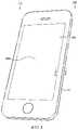
- FIG. 1shows an electronic device having a housing in accordance with embodiments herein;
- FIG. 2shows a wearable electronic device having a housing in accordance with embodiments herein;
- FIG. 3 Ais a cross-sectional view of an enclosure having a housing body and cover sheet in accordance with embodiments herein;
- FIG. 3 Bis another cross-sectional view of an enclosure having a housing body and cover sheet in accordance with embodiments herein;
- FIG. 3 Cis a still another cross-sectional view of an enclosure having a housing body and cover sheet in accordance with embodiments herein;
- FIG. 4shows a schematic of thermoforming a glass sheet into a contoured glass sheet
- FIG. 5shows an illustrative view of a female mold face or surface in accordance with embodiments herein;
- FIG. 6shows an illustrative view of a male mold face or surface in accordance with embodiments herein;
- FIG. 7shows a flow diagram for preparing a thermoformed glass article having hard ceramic powder embedded therein
- FIG. 8shows a cross-sectional schematic view of a cover sheet having hard ceramic powder imbedded therein by thermoforming
- FIG. 9shows a flow diagram for preparing a thermoformed glass article having alkali metal strengthening
- FIG. 10 Ashows a flow diagram for preparing a thermoformed glass article with increased density using multiple mold cooling zones
- FIG. 10 Bshows a flow diagram for preparing a thermoformed glass with increased density using multiple mold parts under differential pressure requirements
- FIG. 11shows a schematic of thermoforming a glass sheet into a contoured glass sheet have one or more zones of textured surface
- FIG. 12shows a schematic for thermoforming a glass sheet into a contoured glass sheet having one or more zones of superhydrophobicity
- FIG. 13shows an illustrative view of a glass surface face having a superhydrophobic imprint
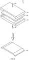
- FIG. 14shows a schematic of thermoforming two dissimilar materials into a bonded contoured sheet in accordance with an embodiment herein;
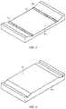
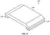
- FIG. 15shows a schematic of thermoforming two dissimilar materials into a bonded contoured sheet in accordance with an alternative embodiment herein;
- FIG. 16shows a flow diagram for preparing a thermoformed glass article having two separate glass sheets bonded together, each glass sheet having a different coefficient of thermal expansion (CTE);
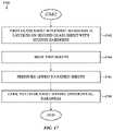
- FIG. 17shows a flow diagram for preparing a thermoformed glass article having two separate glass sheets bonded together, each glass sheet having a different hardness
- FIG. 18shows a flow diagram for preparing a thermoformed glass article having two separate glass sheets bonded together, each sheet having a different capacity for ion diffusion;
- FIG. 19shows a flow diagram for preparing a thermoformed glass article having two separate glass sheets bonded together, each sheet having a different Young's modulus
- FIG. 20shows a flow diagram for preparing a thermoformed material having one glass sheet and one ceramic sheet bonded together
- FIG. 21 Ashows a schematic of two glass sheets with uneven surfaces in need of joining
- FIG. 21 Bshows a schematic of the two glass sheets in FIG. 21 A having a cladding layer positioned there-between;
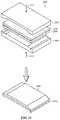
- FIG. 21 Cshows a schematic of thermoforming two dissimilar materials with a sandwiched cladding layer into a bonded contoured sheet in accordance with an embodiment herein.
- cross-hatching or shading in the accompanying figuresis generally provided to clarify the boundaries between adjacent elements and also to facilitate legibility of the figures. Accordingly, neither the presence nor the absence of cross-hatching or shading conveys or indicates any preference or requirement for particular materials, material properties, element proportions, element dimensions, commonalties of similarly illustrated elements, or any other characteristic, attribute, or property for any element illustrated in the accompanying figures.
- the following disclosurerelates to glass articles, methods of producing glass articles, and to the utility of such glass articles in an electronic device.
- Embodimentsalso relate to an increase in the strength, hardness and/or elasticity of glass, especially related to glass in an electronic device, as well as to the cosmetic feel or superhydrophobicity (a glass surface that is hydrophobic and prevents water retention) of glass in an electronic device.
- Methods of producing such glass articlesrelate to thermoforming glass to a desired contour or geometry while, at the same time, enhancing one or more of its mechanical characteristics or properties.
- a mechanical characteristic or propertyrefers to strength, hardness, elasticity, tactile feel, superhydrophobicity, and the like.
- thermoforming a glass sheet to a desired contour shape and property attributeThe glass sheet can have one or more mechanical characteristics.
- the mechanical characteristicis present in the glass sheet prior to the thermoforming processes described herein. Utilization of modified thermoforming processes alleviates the need for additional post processing treatments, particularly as these treatments relate to an electronic device. Modifications to the thermoforming process, thermoforming molds, and glass formed by thermoforming allows for a significant improvement in glass for a particular use, as well as to the methods for manufacturing the glass for a particular use. In this manner, the mechanical characteristic of the glass sheet is altered to an improved mechanical characteristic, for example, an improvement in glass strength, hardness, elasticity, texture and the like.
- the glass articlemay be an outer surface of an electronic device.
- the glass articlemay correspond to a cover sheet that helps form part of a display area, or, in some instances, be involved in forming part of the housing.
- a displaymay comprise a transparent window.
- the embodiments hereinare particularly relevant for use in portable electronic devices, and small form factor electronic devices, e.g., laptops, mobile phones, tablet computers, smart watches, media players, health-monitoring devices, remote control units, and the like.
- Typical glass articles hereinare thin, and typically less than 5 mm in thickness, and more typically less than 3 mm in thickness.
- the glass articlecan be from about 0.1 mm to 2 mm in thickness, and more typically from 0.15 mm to 1 mm in thickness.
- FIGS. 1 - 21These and other embodiments are discussed below with reference to FIGS. 1 - 21 . However, those skilled in the art will readily appreciate that the detailed description given herein with respect to these Figures is for explanatory purposes only and should not be construed as limiting.
- FIG. 1illustrates one embodiment of a portable electronic device 100 .
- the portable electronic device 100includes a glass article 102 (which in this case is a cover sheet) and an enclosure or housing 104 .
- the cover sheet 102can have a front surface 106 , back surface (not shown), and side surfaces (not shown).
- the various surfacescan be composed of zones and/or portions.
- An example zone of the cover sheetcould be the entire front surface 106 , while the back surface would be considered a different zone.
- the cover sheet 102may also define a window region through which the display of the device is visible.
- Various properties of the zonesmay differ on the use, for example, a front surface, exposed to the outside environment, may require a different mechanical property or characteristic, hardness for example, than the back surface, enclosed away from the environment.
- the enclosureincludes a housing body 108 and cover sheet 102 that together define an interior volume that is configured to enclose the various electronic components of the device.
- the housing body 108may define an opening in which a display is positioned.
- the cover sheet 102is positioned over the display and forms a portion of the exterior surface of the device.
- the displaymay include a liquid crystal display (LCD), an organic light-emitting diode (OLED) display, a transparent window, or other suitable display elements or components.
- LCDliquid crystal display
- OLEDorganic light-emitting diode
- the cover sheet 102has been thermoformed to a required contoured shape for the electronic device, with enhanced properties.
- Enhanced propertiescan be localized to specific zones of the cover sheet 102 or can be globally modified during the thermoforming process.
- Some embodiments hereinutilize property-enhancing materials to improve scratch resistance, hardness, and strength, and the like, for example.
- the contoured shape of the cover sheetforms a continuous curved surface with the housing body.
- FIG. 2illustrates another embodiment of a portable electronic device, in this case a wearable electronic device 200 .
- the glass article 202 in this illustrative embodimentis a thermoformed cover sheet with enhanced strengthening.
- a watch housing body 204captures the glass 202 .
- the cover sheet 202has a complex shape that includes a pair of curved portions 206 that extend along a corresponding pair or edges of the contoured shape.
- the curved portions 206can be configured during thermoforming to form a continuous curved surface with the housing of the electronic device.
- thermoforming various glass article geometriescan eliminate the need for post processing steps and allows for improved manufacturing of electronic device having a need for thin, complex shapes with high tolerances.
- Illustrative buttons 208extend from the device for user interface.
- FIG. 3 Ais an illustrative cross-sectional view of an enclosure 104 along section A-A of a device similar to the one shown in FIG. 1 .
- a housing body 108composed of an aluminum alloy, ceramic or other like material defines an opening.
- a thermoformed cover sheet 102is attached to the housing body 108 to cover the opening and define an enclosed volume 109 .
- the housing bodyhas an internal 110 and external surface 112 , where the internal surface 110 supports and surrounds various structural and electronic components of the mobile phone (not shown).
- the cover sheet 102has a front surface 114 , back surface 116 , and side surface 118 .
- the cover sheet 102is positioned over the display 111 .
- Each surface of the cover sheetcan be composed or one or more zones or portions.
- the front surface 114 of the cover sheet 102is exposed to the environment, while the back surface 116 is exposed to the enclosed volume 109 of the illustrative electronic device 100 .
- the cover sheet 102is thin, and typically less than 5 mm in thickness, and in most cases less than 3 mm in thickness. In some aspects, the cover sheet has a thickness of from about 0.1 mm and 2 mm, and in other aspects from about 0.15 mm to 1 mm.
- the cover sheet 102can be shaped to a desired contour during thermoforming so as to fit the use, including at the side surfaces 118 (or edges), where a pair of curved portions can occur. As shown in FIG. 3 A- 3 C , the curved portions 120 can be configured to form a continuous curved surface with the housing body 108 of the electronic device 100 .
- FIG. 3 Bshows a similar cross-sectional view of an enclosure 104 , as shown in FIG. 3 A , except the thermoformed cover sheet 102 extends to form a top half of the enclosure, while the housing body 108 has a symmetrical curve 122 to form the bottom half of the enclosure.
- the cover sheet 102 in this embodimentshows a more pronounced curvature 120 , as available through the thermoforming process.
- An antenna 124 and insulation 126is also shown.
- a displayis shown. Post machining the curvature shown in the cover sheet of FIG. 3 B would be difficult to impossible to attain from a starting piece of flat glass sheet.
- FIG. 3 Cshows another cross-section view of an enclosure, as shown in FIG. 3 A , having a highly contoured cover sheet 102 , matching housing body 108 .
- the thermoformed glassshows a pronounced curvature 120 , not available in post-processing of a flat glass sheet.
- a display 111is provided for reference.
- Glass for use hereincan be composed of a transparent glass and can include a combination of SiO 2 , Al 2 O 3 , B 2 O 3 , Na 2 O, ZnO, Li 2 O, and other known constituents.
- the glassis ion-exchangeable and composed of a lattice having a defined volume.
- Glass sheetsrepresent glass materials prior to thermoforming, and may include various types and kinds of glass feedstock. Glass sheets have a size, thickness and composition useful for the intended use after thermoforming and property enhancement.
- the property or characteristicis a mechanical property or characteristic, and the glass sheet is described as having a first mechanical property or characteristic that is altered by the thermoforming process to a second mechanical property or characteristic.
- Glass sheetscan also be described as having a glass substrate such that the glass substrate can be modified with a surface layer of performance-enhancing materials. Glass substrates typically are formed of glass silicates or similar type compounds as is known in the art.
- FIG. 4illustrates a simplified schematic of thermoforming a glass sheet to a desired contoured shape in accordance with embodiments herein 400 .
- a glass sheet 402 in need of a particular shapeis heated under pressure to above its glass transition temperature to form the desired glass article. Heating of the glass sheet does not reach the glass melting point, as this would render the glass completely liquid.
- a glass sheet 102is heated to above its glass transition temperature, but below its melting temperature, and placed in an appropriate mold 404 (or the glass sheet is placed in a heated mold), and pressure applied (illustrated by arrow 406 ) to the glass sheet, in the presence or absence of an applied vacuum (not shown).
- This state of glassis receptive to pressure 406 and allows for contour modifications of the glass, based on the contours and pressure points applied by the mold 404 .
- the geometric shape and thickness of the glass 402can be modified to create the appropriate glass article 408 , for example a cover sheet for an electronic device.
- cover sheetsmay be formed having non-uniform thickness where the utility of the sheet requires.
- the glass 402is also receptive to various property modifications.
- Glass that is thermoformed and being shapedis soft and compliable, and can accept various property modifications, for example, strength, surface hardness, scratch resistant surface, surface tactile feel, surface superhydrophobicity and the like.
- a property or characteristic of the glassmay be modified or altered while the glass is in a soft or rubber-like state.
- the property being modifiedcan correspond to a zone or portion of the surface of the glass (local), or can correspond to an entire surface (global).
- the propertycan be changed to a depth and/or distribution based on a penetration profile that results from the thermoforming process.
- a property-enhancing materialis applied to the zones of a glass sheet in need of improvement.
- the glass sheethas a first mechanical property or characteristic.
- the property-enhancing materialis applied prior to the glass thermoforming procedure.
- the property-enhancing materialis applied to the one or more zones of the glass article by a mold, and a mold face or surface in particular.
- a zone or portion of glasscorresponds to a mold surface, or some portion of the mold surface, such that the mold applies the property-enhancing material to the glass sheet surface during the thermoforming process.
- the resultant glasshas an altered mechanical property or characteristic due to the application of the property-enhancing material.
- the property being modified in the glassis an intrinsic property, such as density.
- the mold face or surfaceapplies a change in thermoforming parameters, like temperature or pressure, to modify a property of the glass itself.
- FIG. 5 and FIG. 6illustrate the inside face or surface of the top and bottom mold of FIG. 4 , respectively.
- the mold surfaceis negatively contoured to provide the desired glass article shape during thermoforming.
- the mold surface, or some portion of the mold surface 506can also be utilized to apply a property-enhancing material to the glass sheet, while the glass sheet is in a softened or “thermoplastic” state.
- modification of a glass propertycan be through application of a property-enhancing material, for example a mechanical property, to the glass surface (termed chemical strengthening) via the mold surface 506 .
- a property-enhancing materialfor example a mechanical property
- a hard ceramic powderis deposited locally or globally on the mold surface.
- an alkali metalis deposited locally or globally on the mold surface.
- the hard ceramic powder and alkali metalare referred to as property-enhancing materials.
- the property-enhancing materialscan also be applied to the glass sheet prior to placement in the mold, in such cases the material is coated directly on the glass sheet and then placed in an appropriated mold.
- Application of the property-enhancing material directly to the glass sheetcan be prior to the glass sheet being heated, during heating of the glass sheet or after the glass sheet has been appropriately heated, but prior to the glass sheet being placed in the mold.
- FIG. 7is a flow diagram illustrating a process for increasing the hardness and scratch resistance of one or more zones of a surface in a glass article (for example a cover sheet) 700 .
- a glass sheet that fits the required thickness and area for the intended useis obtained.
- an amount of hard ceramic powderis deposited on the appropriate surface of the glass sheet.
- the sheethas a first mechanical property associated with its hardness.
- the hard ceramic powderis deposited directly to the appropriate glass surface, prior to placement in the mold.
- the hard ceramic powderis applied by an appropriately coated mold surface(s).
- Hard ceramic powders for use hereininclude zirconium (powdered zirconia), sapphire (sapphire powder), and spinel (MgAl 2 O 4 powder), although other like ceramic powders can be used.
- the glass sheetis heated to above its glass transition temperature.
- pressureis applied through the mold, to conform the glass sheet to a contoured shape of the mold to form a contoured sheet.
- the hard ceramic powder located on the mold surfacebecomes embedded in the corresponding zone or zones of the contoured sheet.
- An appropriate amount of heat and pressureis used to deposit the hard ceramic powder to an appropriate depth and distribution in the contoured sheet, termed the penetration profile.
- the cover sheetforms during cooling of the contoured sheet, having a penetration profile for the hard ceramic powder imbedded in its surface.
- the imbedded hard ceramic powdergives the cover sheet improved hardness and scratch resistance wherever the powder has been incorporated.
- one, two or more, three or more, four or more, etc. different hard ceramic powderscan be used to provide a desired hardness/scratch resistance.
- the powderscan be used alone in a zone, or can be combined and then used in a zone.
- a uniform distribution of hard ceramic powderis incorporated into the surface of the entire cover sheet.
- the entire front surface of a cover sheetcan be imbedded with hard ceramic powder, while the back surface remains untreated.
- only a portion of the front surface of the cover sheetis embedded with hard ceramic powder, the portion corresponding to greater user interaction.
- Thermoforming parametersheat, pressure, cooling rate, presence of vacuum, and the like
- Thermoforming parameterscan be altered or modified to imbed the property-enhancing material to a required depth in the glass article.
- the resultant inclusion of the property-enhancing materialprovides a penetration profile for that material. For example, use of higher pressure, greater temperature, or both, will typically result in a profile having a deeper distribution of the property-enhancing material into the glass thickness.
- FIG. 8shows the differential incorporation of hard ceramic powder into a surface of a glass article upon thermoforming 800 .
- the glass article 802along any surface area 804 , can incorporate the hard ceramic powder 806 to a particular depth and concentration based on the thermoforming parameters and the amount of hard ceramic powder deposited on the glass surface, and therefor incorporated into the glass article when thermoformed.
- the hard ceramic powdermodifies the glass surface and glass internal stress relationship.
- the incorporation of the powdergenerally increases the glass compression and adds hard powder to the glass composition, the combination of which provides a hardened, and scratch resistant, surface.
- the front 808 , back 810 and side 812 surfaces of the cover sheet 802have been modified to include hard ceramic powder 806 .
- the hard ceramic powderwas embedded to a consistent depth and distribution, penetration profile. As discussed above, numerous embodiments are available to alter the penetration profile, so for local distribution of the hard ceramic powder, or for differences in the depth and concentration of the hard ceramic powder into a surface of the glass article, and the like.
- FIG. 9is a flow diagram illustrating a process for increasing the chemical strength of one or more zones of a surface in a glass article 900 , i.e, via alkali metal incorporation.
- Alkali treating of a glass articleeffectively strengthens the surface of glass by adding stress to the glass.
- the combination of stresses on a glass articleare budgeted to avoid failure and maintain safety, i.e., if you put too much stress into a glass article, the energy will eventually cause the article to break or fracture. Therefore, each glass article has a stress budget, an amount of compressive stress verse tensile strength that provides a safe and reliable glass article.
- alkali metal ionsare added to the glass surface to a depth of particular utility. Ions that diffuse into the glass article surface form a compressive stress layer that enhances the surfaces strength.
- a glass sheet that fits the required thickness and area for the intended useis obtained.
- the required contour shape and strengthis identified for the cover sheet, including zones or portions of the cover sheet in need of an increase in strength.
- Both symmetric and asymmetric chemical strengtheningis contemplated for this embodiment, where the effect of chemical strengthening the glass sheet during thermoforming will keep the inner portion of the cover sheet under tension, while the chemically strengthened layer will be under compression.
- the depth and compression of the chemically strengthened layerwill vary upon the requirements of a particular use, but will depend on the type of alkali ion incorporated into the glass (partly based on the ions size and ability to add compression to the limited volume of the glass) and the thermoforming parameters used to diffuse the ions into the softened glass.
- the alteration in the mechanical property, strengthening,will result in a penetration profile for the glass sheet.
- an alkali metalis deposited on a glass sheet surface, typically via direct contact with the glass sheet or through contact via a corresponding mold face or surface.
- the glass sheethas a first mechanical property, in this case strength, prior to the thermoforming process.
- the alkali metalis deposited on the mold surface via a alkali metal rich liner, or via a coating or paste.
- the alkali metalis sodium, particularly where the glass is a silicate or soda lime glass, or where the glass has been enriched with lithium.
- the sodium ionswill diffuse into the thermoformed glass surface and form a local or global (depending on the deposit to the mold surface) surface compression layer.
- the alkali metalis potassium, particularly where the glass article already incorporates sodium, and requires a larger ion to add compression to the surface.
- the glass sheetis thermoformed (heated first and pressure added second) into the correct contoured shape (contoured sheet), while incorporating the alkali metal into the glass surface.
- the contoured sheetis cooled into a cover sheet, having a distributed ion, like sodium or potassium, diffused in the surface of the target zones (penetration profile).
- the first mechanical propertyhas now been altered to a second mechanical property consistent with the incorporation of the alkali metal.
- the strengthening of the cover sheetis symmetric.
- the glasswill be strengthened asymmetrically. Asymmetric strengthening allows for an increase in strengthening at that localized portion or zone of the glass, i.e., a strengthened layer, as the surface compression layer is localized to one side of the glass (front versus back in this example).
- Additional embodiments hereininclude immersing the thermoformed and chemically strengthened glass article, for example cover sheet, in an ion solution bath to further modify and/or enhance the glass articles strength.
- a glass article having been thermoformed and strengthened by addition of sodium ionmay be further strengthened by immersion in a potassium salt solution bath at an appropriate temperature and for an appropriate amount of time.
- a glass articlemay be designed to include multiple zones of symmetric and asymmetric chemical strengthening, formed through a combination of thermoformed chemical strengthening followed by chemical strengthening in ion solution baths.
- a glass article feedstockcould first be chemically strengthened via ion bath immersion, for example in a sodium salt solution, followed by targeted strengthening during thermoforming to the geometric shape of the glass article, for example, lining one zone of a mold surface with potassium ion.
- chemical bath strengtheningmay also include use of masking or ion-diffusion barriers to cover portions of the glass article prior to immersion in the ion containing baths, or can include materials to promote ion diffusion into the glass article, e.g., high concentration ion pastes or coatings.
- a glass articlemay include hard ceramic powder and alkali ion strengthening, both incorporated during the same thermoforming process.
- a zone of the moldcould be coated with zirconia, while another zone of the mold lined with a sodium rich liner.
- a zonemay include both a hard ceramic powder and an alkali metal ion (same zone include both zirconia and sodium ions). In this manner, the hardness and strength of a glass article can be modified during the same thermoforming procedure.
- the moldis physically modified to alter portions of the mold surface to have a different cooling rate, or capacity to exert pressure. Cooling or pressure changes on various portions of the glass sheet can modify the glass articles' density (densification) and thereby its performance, as is discuss in more detail below.
- the property enhancementis accomplished by modification of the thermoforming parameters themselves.
- Embodiments hereinillustrate a thermoforming mold embodiment where the mold itself includes a number of different zones capable of differential cooling or differential pressure inducement.
- the moldmodifies an intrinsic property of the glass via the thermoforming process itself.
- the thermoforming processcan be used to modify the density of different portions or zones of the glass article. An increase in glass density, densification, at the surface of a glass can have an effect on the hardness at the surface, for example.
- a thermoforming moldcan cool at different rates to induce a stress profile in the glass article to result in differential densification of the glass article.
- the glass lattice structurecan be modified to provide different volumes for ions to move through, and thus surface areas of hardness or scratch resistance to occur. For example, where a mold zone is cooled at a lower rate, than an adjacent zone, the slower cooling rate results in the glass being more dense at room temperature, than a zone where a fast cooling rate is performed.
- the slower cooling ratesallow structural equilibrium/relaxation in the glass to be maintained during cooling, whereas fast cooling results in the relaxation becoming fixed and therefor the density becoming fixed.
- thermoforming moldcan also exert pressure at different rates to induce compression in the glass article to result in differential densification of the glass article. So in one zone of the mold, the pressure may be enhanced as compared to an adjacent zone of the mold. The zone where the pressure is greater will result in a glass article having a compressed glass volume in that zone and thereby show greater densification. The adjacent zone, under lower pressure, would have greater volume for ions to move through than the densified zone.
- FIG. 10 Ais a flow diagram illustrating production of a glass article having modified glass density 1000 .
- a glass sheet that fits the required thickness and area for the intended useis obtained.
- the required geometric or contoured shapeis identified for the cover sheet, including zones or portions of the cover sheet in need of an increase or decrease in density.
- an appropriate moldis modified to exhibit the required cover sheet density pattern. Molds may be modified through the use of different mold materials, having different thermal conductivity, or may be altered to include cooling lines that run below the surface of the mold, such that the temperature of the cooling fluid can be modified to adjust the temperature at the surface of the mold.
- Control over a cooling zone in the moldallows for control over the cooling rate of the glass sheet, and thus the glass sheet density at that corresponding zone.
- the glass sheetis thermoformed to a geometry for a particular use, using the cooling modified mold as described herein.
- the heated and formed glass sheetis a contoured sheet.
- the glass sheetis differentially cooled in the mold to result in a cover sheet having modified glass surface densities, and therefore, hardness.
- a mold in accordance with embodiments described abovemay result in a cover glass where the density of the glass is increased on the front surface, but remain unchanged on the back surface, for example.
- zones on the front or back sheethave locally modified glass density that correspond to a particular need.
- the density of zones on the front surfacecan be densified where user interactions are required.
- FIG. 10 Bis a flow diagram illustrating production of a glass article also having modified surface glass density 1010 .
- a glass sheet that fits the required thickness and area for the intended useis obtained.
- the required geometric shapeis identified for the final glass article, a cover sheet for example, including zones or portions of the glass article in need of an increase or decrease in density.
- an appropriate moldis modified to exhibit the required glass article density pattern.
- Multi-part moldsmay be modified to exert differential pressure on different zones or portions of the glass sheet.
- a moldmay be composed of multiple parts, where each part is controlled to exert an independent pressure or force.
- Mold partsmay include a single top mold, and a single bottom mold (able to exert different levels of force), or a top mold composed of two independent parts under independent control (able to exert two different levels of force through the top mold), and a single bottom mold (able to exert one level of force). Mold parts may include any combination that would be useful in forming a desired density pattern on a glass article, including molds that have multiple top and bottom parts, each under its own pressure control.
- the multi-part moldis heated to above the glass transition temperature (or the mold is not heated but the glass pre-heated to above the glass transition temperature), followed by the differential application of pressure to zones of the glass sheet.
- the differential pressureresults in formation of the glass sheet contoured shape as well as differential density zones upon cooling.
- the formed glass sheetis a contoured sheet. As noted above, having a glass sheet with modified density allows for inclusion of higher density and scratch resistance.
- the contoured sheetis then cooled in accordance with embodiment herein in operation 1018 .
- a glass article having one or more different surface densitiescan be further manipulated using chemical strengthening.
- Chemical strengtheningis limited by the saturation limit of the glass for an amount or volume or ions. At saturation, no additional compression layer or depth may be accomplished.
- a more limited lattice structureis available for ion diffusion.
- the increased density in the glass surfaceallows fewer ions to move inwardly, while the concentration of the ion increases at the surface of the glass.
- Additional chemical strengthening in a densified glass surfaceresults in a glass surface having a shallow compression layer. Shallow compression layers with increased ion inclusion form a shallow, hard surface that is resistant to scratching, for example, i.e., are scratch-resistant.
- glass sheetscan be modified to include chemical strengthening on top of normal to densified glass. This allows for a wide array of glass treatments during the thermoforming process to prepare a glass article of numerous useful properties.
- the glass texture on a glass articleis controlled by having a texture imprinted (texturing) in the glass surface during the thermoforming process (thereby forming a textured surface).
- softened glass during the thermoforming processcan be imprinted with a textured pattern, typically via a mold surface or face. The negative imprint or pattern of the mold surface is used to add texture to the glass sheet while the glass sheet is undergoing the thermoforming contour changes required for the cover sheet or other like glass article.
- a mold 1100 having a negative imprint or pattern of a desired textureis used to thermoform a desired glass article 1102 (part of a thermoform molding machine).
- the moldexhibits the corresponding negative texture pattern 1104 as required in the glass article 1106 , as shown in the corresponding exploded view.
- the mold surface or face 1108 , having the negative imprint 1104is heated to above the glass transition temperature and pressure applied (arrow 1105 ) to imprint the textured pattern on the softened glass.
- the molddoes not have to be heated, where the glass sheet 1110 is first heated to above the glass transition temperature, and then placed in the mold 1100 .
- the moldmay have portions that include the textured pattern and portions that remain smooth.
- textured and smooth portions of the moldmay be adjacent to one another.
- various different textured patternsmay form portions adjacent one another.
- zones or portions of the glass surfacehave the imprinted texture 1106 , and are cooled to form the desired glass article having the desired glass article contoured shape.
- the resultant glass article 1102can have localized or global texture added to the glass surface useful for an improved tactile feel, or enhanced capability for the function of the glass surface, bonding other materials due to its enhanced surface area, for example (e.g., Datum bonding to a frame/anti-splinter film), i.e., function.
- Texture addition to a glass article hereincan also allow for a glass surface having a controlled texture gradient, useful in functional attributes like Haze Control for various sensors or displays. Texture can be added in zones or portions of the glass and can be accomplished by gradients or steps.
- the addition of texture to a glass article during the thermoforming processis a significant advantage over chemical etching of texture into an already formed glass article, both in complexity and precision.
- the textured surface added by the thermoforming processis substantially free of the damage caused by chemical etching, for example, scratching or etching damage. Any useful texture can be added to a glass article herein as long as the negative imprint can be accommodated on the thermoforming mold surfaces.
- the glass articlecan exhibit an average surface roughness of from 0.5 to 10 ⁇ m and more typically 0.5 ⁇ m to 7 ⁇ m.
- FIG. 12 and FIG. 13show an illustrate mold 1200 (part of a thermoform molding machine) for use in accordance with embodiments herein.
- a mold face 1202is prepared, i.e, media blasted, machined, etched, to include a desired negative imprint for inclusion on the glass article surface 1204 .
- inclusion of a texture to a glass article during the thermoforming processis a significant improvement over etching or machining each completed glass article after formation, this is particularly true where significant numbers of textured articles are needed.
- the textured surfaceis substantially free of damage caused by chemical etching, particularly scratching or etching damage.
- FIG. 13shows addition of a superhydrophobic surface 1206 to a glass article 1208 using the thermoforming processes in accordance with embodiments herein.
- a negative hydrophobic pattern 1210is formed on the mold 1200 used in the thermoforming process discussed above.
- FIG. 12 and FIG. 13show the hydrophobic pattern 1210 can be applied to all or a portion of the mold surface by laser ablation.
- the process for laser ablation on a mold surfaceis achievable due to the metal's high material opacity. However, this same laser ablation procedure has shown little positive effect when performed on glass (glass has a high transparency).
- transfer of the superhydrophobic surface from the metal mold surface 1202 to the glass article surface 1208 during thermoformingprovides a significant achievement in glass surface utility.
- the imprint pattern required for a superhydrophobic surfaceis on the nanoscale.
- the superhydrophobic surfacecan include an array of protrusions having a diameter of less than 50 nm. In some cases, the protrusions have a diameter of less than 30 nm.
- a glass surface that exhibits a superhydrophobic surfaceis able to resist water, debris, and fingerprinting. The capacity to form a hydrophobic surface in the absence of laser ablation to the glass surface is a significant advancement in the glass forming art.
- the superhydrophobic surfacecan be included globally on the glass article, or can be included only on select zones, dependent on the targeted use.
- Embodiments hereinalso include thermoforming two or more dissimilar materials together so as to join them and form one unitary material with different bulk material properties. As above, the joining occurs while the unitary material is being thermoformed into a contoured desired shape.
- Dissimilar materials hereincan be glass articles having different material properties, i.e, coefficient of thermal expansion, hardness, strength, Young's Modulus, and the like, or can be two different materials all together, for example, joining a glass sheet with a ceramic sheet.
- the materialscan be the same shape, size and thickness or can be of different shapes, sizes and thicknesses.
- the dissimilar materialshave a joining surface that is flat and smooth and allows for the thermoforming process to integrate the contacting surfaces into one co-material, but where the surfaces do not form sufficient contact, a cladding layer may be sandwiched between the dissimilar materials to allow for formation of a unitarily joined, and contoured end material.
- FIG. 14illustrates a simplified schematic of thermoforming two dissimilar materials into a single part having a desired contoured shape in accordance with embodiments herein 1400 .
- this embodimentcan be applied to numerous types of materials, it will be discussed in relation to glass sheets having dissimilar material properties or to a glass sheet and ceramic combination. Also, it can be envisioned that more than two dissimilar materials can be thermoformed into a single part having a desired shape, however, the description will be limited to two with the understanding that additional materials can be added to the thermoforming process, for example, 3, 4, 5 and the like, to form a single part.
- the two dissimilar materials, top 1402 and bottom 1404are layered on each other and positioned in a mold (part of a thermoform molding machine) 1406 to be contoured under heat and pressure.
- the two materials, 1402 and 1404must be heated to above each materials glass transition temperature, but not above either materials melting temperature. As above, the heating of the materials can be performed in a vacuum. Heating the two materials, for example two different glass sheets, above each materials glass transition temperature will result in the two materials being joined or bonded into one single sheet or part 1408 along the contact surface 1410 . As noted above, the contact surface of each glass sheet must be smooth. This same state of the two materials also allows for the joined sheet to be receptive to pressure (arrow 1412 ) that allows for contour modifications.
- FIG. 15illustrates joining two dissimilar materials that have different material properties and sizes/thicknesses 1500 .
- the second material 1502is joined to only a portion or zone of the first material 1504 , in order to provide a particular outer geometer, for example.
- joining multiple layers of material, having differing material properties, shapes and thicknessesprovides a significant advantage over conventional machining or post production processes.
- a matrix of different opportunitiescan be utilized to form an appropriate final part having the correct shape, material property and thickness.
- FIG. 16is a flow diagram illustrating a process for bonding two glass sheets together to form a cover sheet having a top surface under compression as compared to a bottom surface 1600 .
- the two glass sheets having differing coefficients of thermal expansion (CTE)are joined.
- the two sheetsare heated under pressure and contract differently due to their differences in CTE, while the unitary part is thermoformed to a specified contour shape.
- a first glass sheet having a low CTEis layered on top of a second glass sheet having a high CTE (CTE is relative to each other).
- the joining surfaceis smooth.
- the two glass sheetsare heated to above the glass transition temperature for each sheet.
- pressureis exerted by the mold faces to join the two glass sheets together and form a desired shape of the now joined cover sheet.
- the exerted pressure and heatmust also be sufficient to allow for atomic bonding between the two contacting glass sheets.
- the cover sheetis cooled, where the second glass sheet, having the higher CTE, contracts to a greater degree than the material of the first glass sheet (lower CTE).
- the interfaceprevents the second glass sheet material from fully contracting, but results in the first glass sheet material, i.e., the outer surface of the cover sheet to be under compression.
- the outer surface of the cover sheetwill have asymmetric surface compression that acts to protect the surface from damage introduction.
- the inner material of the cover sheetis away from the environment and at lower risk of damage.
- FIG. 17is a flow diagram illustrating a process for bonding two glass sheets together to form a cover sheet having a top and bottom surface with differing harnesses 1700 .
- the two glass sheets having different hardnessesare joined through thermoforming to form a cover sheet with a desired contour shape.
- the first glass sheet having a high material hardnessis layered on top of a second glass sheet having a lower material hardness.
- the joining surfacemust be smooth.
- the two glass sheetsare heated to above the glass transition temperature for each sheet.
- pressureis exerted by the mold faces to join the two glass sheets together and form a desired shape of the now unitary cover sheet.
- the cover sheetis cooled forming a unitary material where the top surface (corresponding to glass sheet one) is able to resist damage to a greater extent than the bottom surface (corresponding to glass sheet two).
- the hardness of glass sheet oneis consistent with the needs of an exterior surface of an electronic device.
- the second sheetcan be optimized for price and processing since it is located on the interior side of the electronic device.
- the thickness of each sheetcan also be optimized to allow for damage protection on the upper surface of the cover sheet, for example, the first sheet could be 0.5 mm, while the second sheet could be 2 mm thick.
- FIG. 18is a flow diagram illustrating a process for bonding two glass sheets together to form a cover sheet having a top and bottom surface with differing capacity for ion diffusion 1800 .
- Ion diffusioncan be controlled by a number of parameters which are all envisioned to be within the scope of the present disclosure. For example, the composition and ion placement in the glass, density of the glass, ion limiting coatings on the glass, and the like.
- the two glass sheets having different ion diffusion capacityare joined together via thermoforming to form a cover sheet with a desired contour shape.
- the first glass sheet, having rapid ion diffusionis layered on top of a second glass sheet, having lower ion diffusion (relative to each other).
- the joining surfacemust be smooth.
- the two glass sheetsare heated to above the glass transition temperature for each sheet.
- pressureis exerted by the mold faces to join the two glass sheets together, and form a desired shape of the now unitary cover sheet. As above, the pressure and heat must be sufficient to allow for atomic bonding between the two hardness materials.
- the cover sheetis cooled forming a unitary material where the top surface (corresponding to glass sheet one) has a greater capacity to be chemically strengthened than the bottom surface (corresponding to glass sheet two).
- Cover sheets formed as described in FIG. 18can be further processed by alkali metal solution bath treatments. For example, upon cooling, the cover sheet, having dissimilar ion diffusion surfaces, would be subjected to a sodium bath to allow for asymmetric diffusion of sodium ions into the top surface of the cover sheet, as compared to the lower cover sheet surface. Further, potassium ion bath treatment may also be utilized to add compression to the top surface and further strengthen the top or outer surface of the cover sheet as compared to the bottom or inner surface.
- Asymmetric strengtheningis particularly advantageous for cover sheets, where a compression budget exists across a thickness of all glass, but can be maximized to the outer surface—essentially taking some of the compression from the bottom and moving it to the top to keep the budget equal (as compared to symmetrical strengthening, where the two sides must be equally compressed, using the same or equal compression budget, the case where both glass sheets have the same capacity for ion diffusion).
- any number of chemical strengthening stepscan be taken that take advantage of the differential ion diffusion capacity of the jointed glass materials.
- FIG. 19is a flow diagram illustrating a process for bonding two glass sheets together to form a cover sheet having a top and bottom surface with differing Young's Modulus (elastic modulus) 1900 .
- the two glass sheets having different elastic deformation propertiesare joined together via thermoforming to form a cover sheet with a desired contour shape.
- the first glass sheet, having a high Young's Modulusis layered on top of a second glass sheet, having a lower Young's Modulus (relative to each other).
- the joining surfacemust be smooth.
- the two glass sheetsare heated to above the glass transition temperature for each sheet.
- cover sheetis cooled forming a unitary material where the top surface (glass sheet one) resists damage introduction due to its higher elastic deformation properties, whereas the inner or lower surface (glass sheet two) is able to deflect or flex to a relatively greater extent.
- the lower glass sheetwill be positioned on the inside of the enclosure (see FIG. 3 ), where its lower Young's Modulus will allow it to internally bend during failures commonly seen during drop events.
- FIG. 20is a flow diagram illustrating a process for bonding a glass sheet to a ceramic sheet 2000 .
- the ceramic sheet or portionacts as a foundation for the surface glass sheet.
- the ceramic materialcan be a ceramic ring with an appropriate geometry preloaded into a mold.
- the ceramicis acting as a “ceramic foot” on which the glass sheet will be overlaid.
- the first glass sheethaving an appropriate hardness and strength to act as the outer surface of a cover sheet, is layered on top of the underlying ceramic footer. As in previous embodiments, the joining surface must be smooth.
- the glass sheet and ceramic footerare heated to a temperature that allows thermoforming of the glass to the pre-formed ceramic.
- pressureis added to contour the glass sheet to a desired shape (again refer to FIG. 15 ) on the ceramic.
- the glass and ceramic cover sheetis cooled, forming a curved glass surface that can be integrated directly into a housing body.
- Embodiments related to joining two or more dissimilar materials using the thermoforming processes hereinmay include a sandwiched cladding layer.
- the two dissimilar materialsfor example, a ceramic and glass sheet
- do not form a smooth contact surfacean incomplete bond will form. Incomplete bonds between otherwise thermoformed materials results in an unacceptable air gap.
- a cladding layercan be sandwiched between the two dissimilar materials.
- FIG. 21 Ashows a cross-section of two glass sheets that do not form a smooth joining surface 2100 .
- a top sheet 2102 and a bottom or base sheet 2104are layered together, but air gaps exist between the surfaces of each respective sheet 2106 . Where the two sheets undergo thermoforming, with an imperfect joining, the air gaps that forms in the cover sheet minimizes the utility of the cover sheet.
- FIG. 21 Bshows a cross-sectional schematic of two glass sheets with a sandwiched cladding layer 2108 positioned therebetween.
- a cladding layer 2110is positioned between the two glass sheets, 2102 and 2104 , such that the cladding layer 2110 acts to fill in the surface gaps between the two glass sheets.
- the cladding layereliminates air gaps and enhances the bonding formed between the two glass sheets during the thermoforming process 2112 , as show in FIG. 21 C .
- a cladding layer 2110is selected to have enhanced plastic flow at the thermoforming temperature, necessary for the top 2102 and bottom (base) 2104 glass sheets.
- the cladding layer 2110need not provide any additional mechanical properties but rather will remain at the neutral axis of the formed cover sheet.
- multiple cladding layerscan be positioned between the two glass sheets, each cladding layer having a different refractive index.
- a first cladding layer and second cladding layercan be positioned such that the cumulative refractive index for the two layers is 0.
- one or more, two or more, three or more, and the like, cladding layerscan be combined to obtain a combined cladding layer with an appropriate index of refraction.
- the cladding materialis an oxide, like calcium oxide. In other embodiments, the cladding material is a transparent or colored polymer (depending on the use). Typically, cladding layers are added between a glass sheet and ceramic material, or when one or both of the two glass sheets has a surface roughness that prevents atomic bonding during the thermoforming process.
- cladding layerscan be joined to the exterior surface(s) of cover sheets herein as well.
- a cladding layercan be coated to the exterior surface(s) of a glass sheet during the thermoforming processes described herein.
- the cladding layercan also be added to the exterior surface of either the first glass sheet or second glass sheet during the joining of two materials discussed herein.
- the cladding layeris deposited on the exterior surface of a glass sheet so as to fill in any defects or gaps in the glass sheet.
- the cladding layercan be used in conjunction with a cladding layer positioned between two glass sheets to remove gaps, or can be used on two glass sheets or a glass and ceramic sheet joined together in the absence of a cladding layer.
- the cladding layertypically is formed from a glass material that has a melting point lower than the melting point of the exterior surface of the glass sheet.
- cover sheets formed from two dissimilar glass sheetscan have one of the glass sheet surfaces modified with a property-enhancing material during the thermoforming process, the same process that joins the two sheets and contours the cover sheet.
- a cover sheet formed from two materials having dissimilar CTEcould further include a hard ceramic powder embedded in the upper sheet having the lower CTE.
- a cover sheet formed from two materials having dissimilar elastic propertiescould further include a localized strengthening in the surface of the glass sheet having a higher Young's Modulus. Cladding layers may be required, either internally between two dissimilar glass sheets or exterior, to fill in defects on any surface of a glass sheet.
- any useful combinationcan be utilized to maximize the glass article's utility.
- all embodiments described hereinmay be further treated via chemical strengthening baths, annealing or other glass modifying techniques.
- the many options created in the embodiments hereinprovide for design and formation of a significant number of useful glass articles, particularly in the electronics industry, where the cover sheets require well suited properties for a particular use.
Landscapes
- Chemical & Material Sciences (AREA)
- Engineering & Computer Science (AREA)
- Materials Engineering (AREA)
- Organic Chemistry (AREA)
- Life Sciences & Earth Sciences (AREA)
- Chemical Kinetics & Catalysis (AREA)
- General Chemical & Material Sciences (AREA)
- Geochemistry & Mineralogy (AREA)
- Composite Materials (AREA)
- Dispersion Chemistry (AREA)
- Ceramic Engineering (AREA)
- Mechanical Engineering (AREA)
- Surface Treatment Of Glass (AREA)
- Re-Forming, After-Treatment, Cutting And Transporting Of Glass Products (AREA)
Abstract
Description
Claims (20)
Priority Applications (7)
| Application Number | Priority Date | Filing Date | Title |
|---|---|---|---|
| US15/676,860US11535551B2 (en) | 2016-09-23 | 2017-08-14 | Thermoformed cover glass for an electronic device |
| PCT/US2017/051128WO2018057342A1 (en) | 2016-09-23 | 2017-09-12 | Thermoformed cover glass for an electronic device |
| CN201780058943.1ACN109923078A (en) | 2016-09-23 | 2017-09-12 | Thermoformed cover glass for electronic devices |
| US16/143,309US11565506B2 (en) | 2016-09-23 | 2018-09-26 | Thermoformed cover glass for an electronic device |
| US16/262,855US10800141B2 (en) | 2016-09-23 | 2019-01-30 | Electronic device having a glass component with crack hindering internal stress regions |
| US17/033,022US11850822B2 (en) | 2016-09-23 | 2020-09-25 | Electronic device having a component with crack hindering internal stress regions |
| US18/388,519US20240075713A1 (en) | 2016-09-23 | 2023-11-09 | Electronic device having a glass component with crack hindering internal stress regions |
Applications Claiming Priority (4)
| Application Number | Priority Date | Filing Date | Title |
|---|---|---|---|
| US201662398616P | 2016-09-23 | 2016-09-23 | |
| US201662398611P | 2016-09-23 | 2016-09-23 | |
| US201662398627P | 2016-09-23 | 2016-09-23 | |
| US15/676,860US11535551B2 (en) | 2016-09-23 | 2017-08-14 | Thermoformed cover glass for an electronic device |
Related Child Applications (1)
| Application Number | Title | Priority Date | Filing Date |
|---|---|---|---|
| US16/143,309Continuation-In-PartUS11565506B2 (en) | 2016-09-23 | 2018-09-26 | Thermoformed cover glass for an electronic device |
Publications (2)
| Publication Number | Publication Date |
|---|---|
| US20180086663A1 US20180086663A1 (en) | 2018-03-29 |
| US11535551B2true US11535551B2 (en) | 2022-12-27 |
Family
ID=61687629
Family Applications (1)
| Application Number | Title | Priority Date | Filing Date |
|---|---|---|---|
| US15/676,860Active2039-02-08US11535551B2 (en) | 2016-09-23 | 2017-08-14 | Thermoformed cover glass for an electronic device |
Country Status (3)
| Country | Link |
|---|---|
| US (1) | US11535551B2 (en) |
| CN (1) | CN109923078A (en) |
| WO (1) | WO2018057342A1 (en) |
Families Citing this family (21)
| Publication number | Priority date | Publication date | Assignee | Title |
|---|---|---|---|---|
| KR101697158B1 (en)* | 2014-12-19 | 2017-01-17 | 삼성전자주식회사 | Apparatus for forming glass curve and method using the same |
| US10206298B2 (en) | 2016-04-21 | 2019-02-12 | Apple Inc. | Witness layers for glass articles |
| US11419231B1 (en) | 2016-09-22 | 2022-08-16 | Apple Inc. | Forming glass covers for electronic devices |
| US11565506B2 (en)* | 2016-09-23 | 2023-01-31 | Apple Inc. | Thermoformed cover glass for an electronic device |
| US10800141B2 (en) | 2016-09-23 | 2020-10-13 | Apple Inc. | Electronic device having a glass component with crack hindering internal stress regions |
| US11066322B2 (en) | 2017-12-01 | 2021-07-20 | Apple Inc. | Selectively heat-treated glass-ceramic for an electronic device |
| US10611666B2 (en) | 2017-12-01 | 2020-04-07 | Apple Inc. | Controlled crystallization of glass ceramics for electronic devices |
| US11420900B2 (en) | 2018-09-26 | 2022-08-23 | Apple Inc. | Localized control of bulk material properties |
| US11680010B2 (en) | 2019-07-09 | 2023-06-20 | Apple Inc. | Evaluation of transparent components for electronic devices |
| CN110342795A (en)* | 2019-07-31 | 2019-10-18 | 江西沃格光电股份有限公司 | Hot bending die, cover board and preparation method thereof and mobile communication equipment |
| CN110491295B (en)* | 2019-08-26 | 2020-07-17 | 苹果公司 | Display in fabric covered electronic device |
| DE102019217611A1 (en)* | 2019-11-14 | 2021-05-20 | Volkswagen Aktiengesellschaft | Method and device for producing a pane of glass, pane of glass |
| CN115955798A (en) | 2020-03-28 | 2023-04-11 | 苹果公司 | Glass cover member for housing of electronic equipment |
| US11460892B2 (en) | 2020-03-28 | 2022-10-04 | Apple Inc. | Glass cover member for an electronic device enclosure |
| US11666273B2 (en) | 2020-05-20 | 2023-06-06 | Apple Inc. | Electronic device enclosure including a glass ceramic region |
| WO2022133136A1 (en) | 2020-12-17 | 2022-06-23 | Apple Inc. | Fluid forming a glass component for a portable electronic device |
| WO2022133133A1 (en) | 2020-12-17 | 2022-06-23 | Apple Inc. | Forming of glass components for portable electronic devices |
| US11945048B2 (en) | 2020-12-23 | 2024-04-02 | Apple Inc. | Laser-based cutting of transparent components for an electronic device |
| US12408282B2 (en)* | 2022-01-19 | 2025-09-02 | Apple Inc. | Electronic devices having differentially strengthened cover members |
| WO2023210949A1 (en)* | 2022-04-29 | 2023-11-02 | 삼성전자 주식회사 | Electronic apparatus comprising cover glass |
| US12234175B1 (en)* | 2024-04-16 | 2025-02-25 | Corning Incorporated | Glass parts and gob-pressing methods for making such |
Citations (229)
| Publication number | Priority date | Publication date | Assignee | Title |
|---|---|---|---|---|
| US2795084A (en)* | 1954-10-22 | 1957-06-11 | Corning Glass Works | Method of shaping a glass article |
| US3410673A (en) | 1964-01-31 | 1968-11-12 | Corning Glass Works | Double ion exchange method for making glass article |
| US3433611A (en) | 1965-09-09 | 1969-03-18 | Ppg Industries Inc | Strengthening glass by multiple alkali ion exchange |
| US3464880A (en) | 1963-11-21 | 1969-09-02 | Ppg Industries Inc | Surface crystallized glass and method of producing |
| US3737294A (en) | 1970-08-28 | 1973-06-05 | Corning Glass Works | Method for making multi-layer laminated bodies |
| US3746526A (en) | 1971-03-10 | 1973-07-17 | Corning Glass Works | Method for forming subsurface fortified laminates |
| US3899315A (en)* | 1974-04-15 | 1975-08-12 | American Optical Corp | Method of making glass clad glass lenses |
| US4054895A (en) | 1976-12-27 | 1977-10-18 | Rca Corporation | Silicon-on-sapphire mesa transistor having doped edges |
| US4070211A (en) | 1977-04-04 | 1978-01-24 | The United States Of America As Represented By The Secretary Of The Navy | Technique for threshold control over edges of devices on silicon-on-sapphire |
| US4209229A (en) | 1978-09-25 | 1980-06-24 | Corning Glass Works | Glass-ceramic coated optical waveguides |
| US4339300A (en) | 1977-07-25 | 1982-07-13 | Noble Lowell A | Process for smoothing surfaces of crystalline materials |
| JPS6042176A (en) | 1983-08-18 | 1985-03-06 | 本田技研工業株式会社 | Frame structure for saddling type car |
| JPS6271215A (en) | 1985-09-25 | 1987-04-01 | Toshiba Corp | Wafer bonding equipment |
| US4735917A (en) | 1986-04-28 | 1988-04-05 | General Electric Company | Silicon-on-sapphire integrated circuits |
| US4849299A (en) | 1986-06-19 | 1989-07-18 | Montres Rado S.A. | Watch cover glass and process for the manufacture of such a glass |
| JPH03122036A (en) | 1989-06-22 | 1991-05-24 | Toyota Motor Corp | Molding method of glass substrate for curved liquid crystal cell |
| US5122177A (en) | 1990-01-11 | 1992-06-16 | Nippon Sheet Glass Co., Ltd. | Method of and system for pressing sheet glass |
| US5173453A (en) | 1991-10-09 | 1992-12-22 | Corning Incorporated | Variably translucent glass-ceramic article and method for making |
| US5273553A (en) | 1989-08-28 | 1993-12-28 | Kabushiki Kaisha Toshiba | Apparatus for bonding semiconductor substrates |
| US6055053A (en) | 1997-06-02 | 2000-04-25 | Stress Photonics, Inc. | Full field photoelastic stress analysis |
| US6067005A (en) | 1997-10-14 | 2000-05-23 | Devolpi; Dean R. | Multi-speed multi-direction analog pointing device |
| US6169256B1 (en) | 1998-10-23 | 2001-01-02 | Matsushita Electric Industrial Co., Ltd. | Panel switch and method of mounting the same |
| US6406769B1 (en) | 1998-04-02 | 2002-06-18 | Comadur S.A. | Watch crystal including a lens and manufacturing method for such a lens |
| US20030040346A1 (en) | 2001-08-27 | 2003-02-27 | Olympus Optical Co., Ltd. | Portable information terminal device having camera feature |
| US20030062490A1 (en) | 2001-09-28 | 2003-04-03 | Nec Corporation | Imaging device and electronic equipment incorporated therein the same |
| US20040003627A1 (en) | 2002-07-03 | 2004-01-08 | Nihon Yamamura Glass Co., Ltd. | Locally crystallized glass |
| US20040041504A1 (en) | 2002-09-03 | 2004-03-04 | Ozolins Helmars E. | Bezel-less electronic display |
| US20040105026A1 (en) | 1998-12-24 | 2004-06-03 | Campbell Scott Patrick | Contoured surface cover plate for image sensor array |
| US6809278B2 (en) | 2003-03-18 | 2004-10-26 | Matsushita Electric Industrial Co., Ltd. | Electronic equipment and pushbutton used therein |
| US20050135724A1 (en) | 2003-12-19 | 2005-06-23 | Henry Helvajian | Integrated glass ceramic systems |
| US20050166639A1 (en)* | 2004-01-29 | 2005-08-04 | Skeen W. J. | Method of and apparatus for strengthening edges of one or more glass sheets |
| US6928224B2 (en) | 2001-03-09 | 2005-08-09 | Corning Incorporated | Laser-induced crystallization of transparent glass-ceramics |
| US20050176506A1 (en) | 1996-10-11 | 2005-08-11 | Sony Computer Entertainment Inc. | Operating device for game machine |
| US7115827B2 (en) | 2002-08-13 | 2006-10-03 | Jen-Shou Tseng | Button structure and design method for latching prevention |
| US7240519B2 (en)* | 2002-11-18 | 2007-07-10 | Ppg Industries Ohio, Inc. | Apparatus and method for bending glass sheets |
| US20080049980A1 (en) | 2006-08-28 | 2008-02-28 | Motorola, Inc. | Button with integrated biometric sensor |
| US20090040737A1 (en) | 2007-08-07 | 2009-02-12 | Denso Corporation | Portable device for transmitting signal |
| US7497093B2 (en) | 2004-07-29 | 2009-03-03 | 3M Innovative Properties Company | Method of making ceramic articles |
| US7507918B2 (en) | 2007-03-30 | 2009-03-24 | Sony Corporation | Multidirectional input apparatus and electronic device |
| US20090108477A1 (en)* | 2005-11-18 | 2009-04-30 | Hoya Corporation | Method of Manufacturing Formed Article, Glass Material, and Method of Determining Shape of Glass Material and Mold |
| US20090127727A1 (en)* | 2005-11-18 | 2009-05-21 | Hoya Corporation | Method of manufacturing formed article, mold and method of manufacturing the same |
| CN101475300A (en) | 2008-11-20 | 2009-07-08 | 广州兴华玻璃工业有限公司 | Hot bending process for big step glass |
| US20090194913A1 (en)* | 2008-01-31 | 2009-08-06 | National Taiwan University | Method of micro/nano imprinting |
| US20100013786A1 (en) | 2007-03-09 | 2010-01-21 | Kazuhiro Nishikawa | Protective panel with touch input function for electronic apparatus display window |
| US20100108486A1 (en) | 2007-04-18 | 2010-05-06 | Minoru Yoshida | Metal dome sheet having pressing projection, push button switch, and method of producing the push button switch |
| US20100127420A1 (en) | 2008-11-25 | 2010-05-27 | Thierry Luc Alain Dannoux | Method of forming a shaped article from a sheet of material |
| US20100148996A1 (en) | 2008-12-16 | 2010-06-17 | Kinpo Electronics, Inc. | Light guide structure for a keyboard |
| WO2010077845A2 (en) | 2008-12-17 | 2010-07-08 | Electro Scientific Industries, Inc. | Method for laser processing glass with a chamfered edge |
| US7799158B2 (en) | 2007-05-28 | 2010-09-21 | Ngk Insulators, Ltd. | Method for producing crystallographically-oriented ceramic |
| US20100263708A1 (en) | 2009-04-20 | 2010-10-21 | Chris John Reichart | Method for powering a liftgate with solar energy |
| US20100279068A1 (en) | 2009-05-04 | 2010-11-04 | Glen Bennett Cook | Embossed glass articles for anti-fingerprinting applications and methods of making |
| US20100285310A1 (en)* | 2008-01-09 | 2010-11-11 | Central Glass Company ,Limited | Process for Producing Laminated Glass with Inserted Plastic Film and Laminated Glass with Inserted Plastic Film |
| US20100316847A1 (en)* | 2009-05-28 | 2010-12-16 | Horst Schillert | Method for bending and thermally prestressing radiation shielding glass |
| US20100330814A1 (en) | 2009-06-29 | 2010-12-30 | Applied Materials, Inc. | Methods of forming oxide layers on substrates |
| US20110038115A1 (en) | 2006-12-22 | 2011-02-17 | Nokia Corporation | Illumination Arrangement |
| US20110041987A1 (en) | 2009-08-24 | 2011-02-24 | Ngk Insulators, Ltd. | Method for manufacturing composite substrate |
| US7902474B2 (en) | 2008-05-01 | 2011-03-08 | Apple Inc. | Button assembly with inverted dome switch |
| US7915556B2 (en) | 2007-10-25 | 2011-03-29 | Htc Corporation | Input panel and portable electronic device using the same |
| US7966785B2 (en) | 2007-08-22 | 2011-06-28 | Apple Inc. | Laminated display window and device incorporating same |
| US20110177300A1 (en) | 2009-12-17 | 2011-07-21 | Apple Inc. | Dichroic glass for cosmetic appeal in an electronic device |
| US8003217B2 (en) | 2001-08-02 | 2011-08-23 | 3M Innovative Properties Company | Metal oxide ceramic and method of making articles therewith |
| US20110221993A1 (en)* | 2010-03-12 | 2011-09-15 | Roger Wen-Yi Hsu | Method and Apparatus for Improved Retarder of 3D Glasses |
| US20110253520A1 (en) | 2008-12-17 | 2011-10-20 | Jit Ming Bryan Lim | Light diffuser actuator film (ldaf) keypad module |
| US8050019B2 (en) | 2008-03-18 | 2011-11-01 | Research In Motion Limited | Keypad with water and dust protection |
| US20110281093A1 (en)* | 2010-05-14 | 2011-11-17 | Suresh Thakordas Gulati | Damage-resistant glass articles and method |
| WO2012027660A1 (en) | 2010-08-26 | 2012-03-01 | Corning Incorporated | Two-step method for strengthening glass |
| WO2012074983A1 (en) | 2010-11-30 | 2012-06-07 | Corning Incorporated | Glass with surface and central regions under compression |
| US8212455B2 (en) | 2008-01-30 | 2012-07-03 | Ngk Insulators, Ltd. | Piezoelectric/electrostrictive film element and method manufacturing the same |
| US20120176760A1 (en) | 2011-01-10 | 2012-07-12 | Apple Inc. | Systems and methods for grounding a movable component |
| US20120206669A1 (en) | 2011-02-14 | 2012-08-16 | Kim Dongyong | Display apparatus |
| US20120236526A1 (en) | 2011-03-16 | 2012-09-20 | Weber Douglas J | Strengthening variable thickness glass |
| US20120250273A1 (en) | 2011-03-31 | 2012-10-04 | Inventec Corporation | Button structure and electronic device using the same |
| US20120304376A1 (en)* | 2011-06-01 | 2012-12-06 | Safety Tubs Company, Llc | Method of manufacturing a side door for a walk-in tub |
| US20120327325A1 (en) | 2011-06-24 | 2012-12-27 | Lg Display Co., Ltd. | Display Apparatus |
| US20130083506A1 (en)* | 2011-09-29 | 2013-04-04 | Derek W. Wright | Multi-layer transparent structures for electronic device housings |
| US8431849B2 (en) | 2010-09-24 | 2013-04-30 | Research In Motion Limited | Backlighting apparatus for a keypad assembly |
| US8446264B2 (en) | 2010-07-21 | 2013-05-21 | Research In Motion Limited | Portable electronic device having a waterproof keypad |
| US20130128434A1 (en) | 2011-03-17 | 2013-05-23 | Asahi Glass Company, Limited | Colored glass housing |
| US20130141693A1 (en)* | 2011-10-20 | 2013-06-06 | Oakley, Inc. | Eyewear with chroma enhancement |
| US20130236699A1 (en) | 2012-03-06 | 2013-09-12 | Apple Inc. | Sapphire laminates |
| WO2014022681A1 (en) | 2012-08-01 | 2014-02-06 | Gentex Corporation | Assembly with laser induced channel edge and method thereof |
| WO2014022356A1 (en) | 2012-07-30 | 2014-02-06 | Raydiance, Inc. | Cutting of brittle materials with tailored edge shape and roughness |
| US8665160B2 (en) | 2011-01-31 | 2014-03-04 | Apple Inc. | Antenna, shielding and grounding |
| US20140065374A1 (en)* | 2011-04-01 | 2014-03-06 | Asahi Glass Company, Limited | Laminated glass and its production process |
| US20140093702A1 (en) | 2011-06-20 | 2014-04-03 | Asahi Glass Company, Limited | Method for producing laminated glass, and laminated glass |
| US20140116090A1 (en)* | 2012-11-01 | 2014-05-01 | Samsung Corning Precision Materials Co., Ltd. | Apparatus for chemically toughening glass and method of chemically toughening glass using the same |
| US20140151320A1 (en)* | 2012-11-30 | 2014-06-05 | Corning Incorporated | Glass containers with delamination resistance and improved damage tolerance |
| CN103986803A (en) | 2013-02-08 | 2014-08-13 | 宏达国际电子股份有限公司 | Electronic device and manufacturing method thereof |
| US20140272298A1 (en) | 2013-03-15 | 2014-09-18 | Apple Inc. | Layered coatings for sapphire substrate |
| US8840997B2 (en) | 2010-12-29 | 2014-09-23 | Avanstrate Inc. | Cover glass and method for producing same |
| US20140285956A1 (en) | 2012-01-25 | 2014-09-25 | Apple Inc. | Fused glass device housings |
| US20140311882A1 (en) | 2013-04-19 | 2014-10-23 | Mitsumi Electric Co., Ltd. | Switch |
| US20150002993A1 (en) | 2013-06-26 | 2015-01-01 | Dreamtech Co., Ltd | Method of manufacturing fingerprint recognition home key having offset structure of decorative part and structure of fingerprint recognition home key |
| US20150030859A1 (en) | 2013-07-25 | 2015-01-29 | Apple Inc. | Chemical strengthening of anti-reflective coatings (arc) |
| US20150030834A1 (en) | 2013-07-26 | 2015-01-29 | Corning Incorporated | Strengthened glass articles having improved survivability |
| US20150044445A1 (en)* | 2013-08-07 | 2015-02-12 | Corning Incorporated | Laser controlled ion exchange process and glass articles formed therefrom |
| WO2015031420A1 (en) | 2013-08-29 | 2015-03-05 | Corning Incorporated | Ion exchangeable glass containing boron and phosphorous |
| US20150077830A1 (en) | 2013-09-18 | 2015-03-19 | Htc Corporation | Portable electronic device |
| US20150093581A1 (en)* | 2012-06-25 | 2015-04-02 | Nippon Electric Glass Co., Ltd. | Toughened glass substrate and manufacturing process therefor |
| US9001503B1 (en) | 2013-11-27 | 2015-04-07 | Kyocera Corporation | Electronic apparatus |
| US20150104618A1 (en)* | 2012-03-29 | 2015-04-16 | Mitsuboshi Belting Ltd. | Ceramic color paste, ceramic color, glass having ceramic color, and manufacturing method thereof |
| US20150122406A1 (en)* | 2012-06-08 | 2015-05-07 | Corning Incorporated | Process for laminating thin glass laminates |
| US9030440B2 (en) | 2012-05-18 | 2015-05-12 | Apple Inc. | Capacitive sensor packaging |
| US20150163382A1 (en) | 2013-12-11 | 2015-06-11 | Apple Inc. | Cover glass arrangement for an electronic device |
| US20150165548A1 (en) | 2013-12-17 | 2015-06-18 | Corning Incorporated | Edge chamfering methods |
| US20150202854A1 (en)* | 2012-10-02 | 2015-07-23 | Asahi Glass Company, Limited | Laminated glass production method |
| US20150210588A1 (en)* | 2014-01-29 | 2015-07-30 | Corning Incorporated | Bendable glass stack assemblies, articles and methods of making the same |
| US20150212247A1 (en)* | 2013-09-17 | 2015-07-30 | Corning Incorporated | Broadband polarizer made using ion exchangable fusion drawn glass sheets |
| CN104837781A (en) | 2012-12-07 | 2015-08-12 | 日本电气硝子株式会社 | Method for manufacturing reinforced glass plate having curved sections, and reinforced glass plate having curved sections |
| US9110230B2 (en) | 2013-05-07 | 2015-08-18 | Corning Incorporated | Scratch-resistant articles with retained optical properties |
| US20150232366A1 (en)* | 2014-02-18 | 2015-08-20 | Corning Incorporated | Tunable mold system for glass press bending equipment |
| US20150245514A1 (en) | 2014-02-21 | 2015-08-27 | Samsung Electronics Co., Ltd. | Electronic device including physical key |
| US9140522B1 (en) | 2012-09-05 | 2015-09-22 | The United States Of America As Represented By The Secretary Of The Army | Compositionally graded transparent ceramic armor |
| US20150274572A1 (en)* | 2012-11-07 | 2015-10-01 | Nippon Electric Glass Co., Ltd. | Method for manufacturing cover glass for display and device for manufacturing cover glass for display |
| US20150299036A1 (en)* | 2012-11-20 | 2015-10-22 | Ljerka Ukrainczyk | Method of making three dimensional glass ceramic article |
| US9232672B2 (en) | 2013-01-10 | 2016-01-05 | Apple Inc. | Ceramic insert control mechanism |
| US9249045B2 (en) | 2010-07-17 | 2016-02-02 | Schott Ag | Transparent lithium glass-ceramic material, production and use thereof |
| US9263209B2 (en) | 2010-09-02 | 2016-02-16 | Blackberry Limited | Backlighting assembly for a keypad |
| US20160083282A1 (en)* | 2013-04-19 | 2016-03-24 | Corning Incorporated | Methods of forming laminated glass structures |
| WO2016065118A1 (en) | 2014-10-22 | 2016-04-28 | Corning Incorporated | Glass strengthening by ion exchange and lamination |
| US20160121583A1 (en)* | 2013-06-14 | 2016-05-05 | Corning Incorporated | Laminated sealing sheet |
| US20160137550A1 (en)* | 2013-07-08 | 2016-05-19 | Nippon Electric Glass Co., Ltd. | Tempered glass and glass for tempering |
| US9359251B2 (en) | 2012-02-29 | 2016-06-07 | Corning Incorporated | Ion exchanged glasses via non-error function compressive stress profiles |
| US9392706B2 (en) | 2012-03-16 | 2016-07-12 | Lg Electronics Inc. | Mobile terminal |
| US9390930B2 (en) | 2011-09-20 | 2016-07-12 | Applied Materials, Inc. | Surface stabilization process to reduce dopant diffusion |
| CN105765722A (en) | 2013-11-22 | 2016-07-13 | 赫普塔冈微光有限公司 | Compact optoelectronic modules |
| US20160224142A1 (en) | 2015-02-03 | 2016-08-04 | Tpk Touch Solutions (Xiamen) Inc. | Touch device |
| US9429997B2 (en) | 2012-06-12 | 2016-08-30 | Apple Inc. | Electronic device with wrapped display |
| US20160270247A1 (en) | 2015-03-11 | 2016-09-15 | Apple Inc. | Laminating sapphire and glass using intermolecular force adhesion |
| US20160272530A1 (en)* | 2015-03-20 | 2016-09-22 | Corning Incorporated | Molds for shaping glass-based materials and methods for making the same |
| CN106007345A (en) | 2015-03-24 | 2016-10-12 | 肖特股份有限公司 | Method for changing the geometry of glass ceramics and coated glass ceramic article produced by such method |
| US9474174B2 (en) | 2014-05-21 | 2016-10-18 | Kyocera Corporation | Electronic apparatus |
| US20160357294A1 (en) | 2015-06-05 | 2016-12-08 | Asahi Glass Company, Limited | Glass substrate and method for manufacturing the same, cover glass and method for manufacturing the same, personal digital assistant, and display device |
| US20160354996A1 (en)* | 2015-06-03 | 2016-12-08 | Precision Glass Bending Corporation | Bent, veneer-encapsulated heat-treated safety glass panels and methods of manufacture |
| US9524413B2 (en) | 2013-09-09 | 2016-12-20 | Samsung Electronics Co., Ltd. | Apparatus and method for recognizing fingerprint |
| US9522836B2 (en) | 2011-07-25 | 2016-12-20 | Corning Incorporated | Laminated and ion-exchanged strengthened glass laminates |
| US20160377768A1 (en) | 2015-06-25 | 2016-12-29 | Apple Inc. | High-luminance surface |
| CN106341962A (en) | 2015-07-06 | 2017-01-18 | 三星电子株式会社 | Electronic device including glass cover |
| US20170059749A1 (en)* | 2014-05-15 | 2017-03-02 | Asahi Glass Company, Limited | Glass article and production method for glass article |
| CN106485275A (en) | 2016-10-10 | 2017-03-08 | 厦门理工学院 | A kind of cover-plate glass of realizing positions, with liquid crystal display screen, the method fitted |
| US20170066223A1 (en)* | 2015-09-07 | 2017-03-09 | Asahi Glass Company, Limited | Laminated glass |
| US9632537B2 (en) | 2013-09-23 | 2017-04-25 | Apple Inc. | Electronic component embedded in ceramic material |
| US9674322B2 (en) | 2014-05-28 | 2017-06-06 | Kyocera Corporation | Electronic apparatus |
| US9678540B2 (en) | 2013-09-23 | 2017-06-13 | Apple Inc. | Electronic component embedded in ceramic material |
| US20170182739A1 (en)* | 2015-12-29 | 2017-06-29 | Corning Incorporated | Asymmetric processing method for reducing bow in laminate structures |
| US9697409B2 (en) | 2013-09-10 | 2017-07-04 | Apple Inc. | Biometric sensor stack structure |
| US9728349B2 (en) | 2015-07-22 | 2017-08-08 | Chiun Mai Communication Systems, Inc. | Button struture and electronic device with same |
| US20170282503A1 (en)* | 2014-08-28 | 2017-10-05 | Corning Incorporated | Laminated glass article with ion exchangeable core and clads layers having diffusivity contrast and methods of making the same |
| US20170300114A1 (en) | 2016-04-14 | 2017-10-19 | Apple Inc. | Substrate Having a Visually Imperceptible Texture for Providing Variable Coefficients of Friction Between Objects |
| US20170311466A1 (en) | 2016-04-21 | 2017-10-26 | Apple Inc. | Witness layers for glass articles |
| DE102016107630A1 (en) | 2016-04-25 | 2017-10-26 | Schott Ag | Process for the production of a shaped body of glass ceramic with complex geometry and moldings produced in this way |
| WO2017196800A1 (en)* | 2016-05-09 | 2017-11-16 | Corning Incorporated | Glass laminates having a controlled coefficient of thermal expansion and methods for making the same |
| US20170334770A1 (en)* | 2016-05-19 | 2017-11-23 | Apple Inc. | Asymmetric chemical strengthening |
| US20170340518A1 (en)* | 2016-05-31 | 2017-11-30 | Corning Incorporated | Anti-counterfeiting measures for glass articles |
| US9840435B2 (en) | 2011-12-16 | 2017-12-12 | Asahi Glass Company, Limited | Display cover glass and display cover glass fabrication method |
| US20170355633A1 (en)* | 2014-10-30 | 2017-12-14 | Corning Incorporated | Method and apparatus for sealing the edge of a glass article |
| US9846473B1 (en) | 2015-03-25 | 2017-12-19 | Apple Inc. | Display with windows for visible and infrared components |
| US20170364172A1 (en) | 2016-06-21 | 2017-12-21 | Samsung Electronics Co., Ltd. | Cover window and electronic device including same |
| US20180009697A1 (en)* | 2015-03-20 | 2018-01-11 | Schott Glass Technologies (Suzhou) Co. Ltd. | Shaped glass article and method for producing such a shaped glass article |
| US9870880B2 (en) | 2014-09-30 | 2018-01-16 | Apple Inc. | Dome switch and switch housing for keyboard assembly |
| US20180024274A1 (en) | 2016-07-25 | 2018-01-25 | Apple Inc. | Electronic Devices Having Transparent Crystalline Structures With Antireflection Coatings |
| US9890074B2 (en) | 2013-02-21 | 2018-02-13 | Htc Corporation | Electronic device, glass cover and method of manufacturing glass cover |
| US9897574B2 (en) | 2015-09-17 | 2018-02-20 | Corning Incorporated | Methods of characterizing ion-exchanged chemically strengthened glasses containing lithium |
| US20180067212A1 (en) | 2016-09-02 | 2018-03-08 | Apple Inc. | Infrared-Transparent Window Coatings for Electronic Device Sensors |
| US20180088399A1 (en)* | 2016-09-27 | 2018-03-29 | Asahi Glass Company, Limited | Method for producing glass article, and glass article |
| US20180086026A1 (en) | 2016-09-23 | 2018-03-29 | Apple Inc. | Sapphire and glass laminates with a gradient layer |
| US9941074B2 (en) | 2015-11-04 | 2018-04-10 | Asustek Computer Inc. | Key structure and keyboard using the same |
| US9946302B2 (en) | 2012-09-19 | 2018-04-17 | Apple Inc. | Exposed glass article with inner recessed area for portable electronic device housing |
| US20180125756A1 (en)* | 2016-11-04 | 2018-05-10 | Corning Incorporated | Glass bio-containers and methods for manufacturing the same |
| US20180126704A1 (en)* | 2016-11-04 | 2018-05-10 | Apple Inc. | Structured glass for an electronic device |
| CN108017263A (en) | 2017-12-25 | 2018-05-11 | 深圳市海杰瑞实业有限公司 | A kind of 3D glass self-heating bending mould |
| US20180134606A1 (en) | 2015-07-15 | 2018-05-17 | Schott Ag | Method and device for laser-assisted separation of a portion from a sheet glass element |
| US20180154615A1 (en)* | 2015-06-02 | 2018-06-07 | Corning Incorporated | Glass laminate with pane having glass-glass laminate structure |
| CN108285263A (en) | 2017-01-10 | 2018-07-17 | 爱元福科技股份有限公司 | Method for manufacturing curved glass |
| US20180237325A1 (en) | 2015-08-13 | 2018-08-23 | Corning Incorporated | Additive manufacturing processes and manufactured article |
| CN108545917A (en) | 2018-06-22 | 2018-09-18 | 惠州达特尔机器人有限公司 | A kind of glass plate hot bending method and applied to the device in this method |
| CN108600419A (en) | 2018-03-09 | 2018-09-28 | 广东欧珀移动通信有限公司 | Electronic device and its manufacturing method |
| US20180282207A1 (en)* | 2017-04-04 | 2018-10-04 | Asahi Glass Company, Limited | Manufacturing method of processed member, plate member, and opening member |
| CN108632510A (en) | 2018-05-10 | 2018-10-09 | Oppo广东移动通信有限公司 | Shell assembly and electronic equipment |
| US20180304825A1 (en)* | 2015-10-16 | 2018-10-25 | Agc Glass Europe | Method for fixing a glass interior trim element into a motor vehicle |
| US20180304588A1 (en)* | 2015-10-14 | 2018-10-25 | Corning Incorporated | Laminated glass article with determined stress profile and method for forming the same |
| US20180326704A1 (en)* | 2015-11-05 | 2018-11-15 | Corning Incorporated | Laminated glass article with determined modulus contrast and method for forming the same |
| US10133156B2 (en) | 2012-01-10 | 2018-11-20 | Apple Inc. | Fused opaque and clear glass for camera or display window |
| US10141133B2 (en) | 2016-02-19 | 2018-11-27 | Samsung Electronics Co., Ltd. | Electronic device including key |
| US10146982B2 (en) | 2016-08-05 | 2018-12-04 | Primax Electronics Ltd. | Method for assembling fingerprint identification module |
| US20180370843A1 (en)* | 2017-06-22 | 2018-12-27 | Corning Incorporated | Automotive glass compositions, articles and hybrid laminates |
| US20190022979A1 (en) | 2016-09-23 | 2019-01-24 | Apple Inc. | Thermoformed cover glass for an electronic device |
| US20190037690A1 (en) | 2017-07-31 | 2019-01-31 | Apple Inc. | Patterned Bonded Glass Layers in Electronic Devices |
| US20190030861A1 (en)* | 2017-07-27 | 2019-01-31 | Corning Incorporated | Composite laminate with high depth of compression |
| US20190033144A1 (en) | 2017-07-28 | 2019-01-31 | Corning Incorporated | Methods of improving the measurement of knee stress in ion-exchanged chemically strengthened glasses containing lithium |
| TW201912602A (en) | 2017-09-11 | 2019-04-01 | 美商康寧公司 | Devices with bleached discrete region and methods of manufacture |
| US20190160787A1 (en) | 2016-09-23 | 2019-05-30 | Apple Inc. | Electronic device having a glass component with crack hindering internal stress regions |
| US20190161402A1 (en)* | 2017-11-30 | 2019-05-30 | Corning Incorporated | Glass-based articles having stress profiles with high stored energy and methods of manufacture |
| US20190169061A1 (en) | 2017-12-01 | 2019-06-06 | Apple Inc. | Controlled crystallization of glass ceramics for electronic devices |
| US10318783B2 (en) | 2015-09-25 | 2019-06-11 | Lg Electronics Inc. | Mobile terminal |
| US20190177215A1 (en) | 2016-08-31 | 2019-06-13 | Corning Incorporated | Strengthened glass-based articles having filled holes and method of making the same |
| US20190219463A1 (en) | 2016-09-26 | 2019-07-18 | Orihara Industrial Co., Ltd. | Stress measurement device for strengthened glass, stress measuring method for strengthened glass, manufacturing method of strengthened glass, and strengthened glass |
| US10357945B2 (en) | 2012-10-04 | 2019-07-23 | Corning Incorporated | Laminated glass article with ceramic phase and method of making the article |
| US20190263708A1 (en)* | 2016-06-07 | 2019-08-29 | Corning Incorporated | Methods for manufacturing three-dimensional laminate glass articles |
| US10425994B2 (en) | 2013-04-15 | 2019-09-24 | Schott Ag | Glass ceramic cooking plate with locally increased transmission and method for producing such a glass ceramic cooking plate |
| US20190293838A1 (en) | 2018-03-20 | 2019-09-26 | Invensas Bonding Technologies, Inc. | Direct-bonded lamination for improved image clarity in optical devices |
| WO2019199791A1 (en) | 2018-04-09 | 2019-10-17 | Corning Incorporated | Locally strengthened glass-ceramics and methods of making the same |
| WO2019213364A1 (en) | 2018-05-03 | 2019-11-07 | Corning Incorporated | Glass angle limiting filters, methods for making the same, and pulse oximeters including the same |
| US10494860B1 (en) | 2016-08-09 | 2019-12-03 | Apple Inc. | Glazings and processes for producing glazings |
| US20200014780A1 (en) | 2018-07-06 | 2020-01-09 | Apple Inc. | Cover sheet and incorporated lens for a camera of an electronic device |
| US20200039186A1 (en)* | 2018-08-03 | 2020-02-06 | AAC Technologies Pte. Ltd. | Glass sheet processing method and glass sheet processing mold |
| US20200055281A1 (en)* | 2016-12-21 | 2020-02-20 | Lg Chem, Ltd. | Method of manufacturing curved laminated glass and curved laminated glass |
| CN110857865A (en) | 2018-08-23 | 2020-03-03 | 苹果公司 | Electronic device with optical sensor interference mitigation structure |
| US20200095159A1 (en) | 2018-09-26 | 2020-03-26 | Apple Inc. | Localized control of bulk material properties |
| US10702211B2 (en) | 2016-07-15 | 2020-07-07 | Apple Inc. | Sensor window with integrated isolation feature |
| US20200301527A1 (en) | 2019-03-21 | 2020-09-24 | Apple Inc. | Antireflective treatment for textured enclosure components |
| US20200323440A1 (en) | 2019-04-12 | 2020-10-15 | Beijing Shunyuan Kaihua Technology Limited | Blood pressure measurement |
| US20200339472A1 (en)* | 2018-05-21 | 2020-10-29 | Lg Chem, Ltd. | Method of manufacturing curved joined glass sheet and curved joined glass sheet manufactured by the same |
| US10827635B1 (en) | 2019-06-05 | 2020-11-03 | Apple Inc. | Electronic device enclosure having a textured glass component |
| US20200346525A1 (en)* | 2017-12-31 | 2020-11-05 | Agp America S.A. | Vehicle glazing with improved stiffness |
| US20200369560A1 (en) | 2018-02-16 | 2020-11-26 | AGC Inc. | Cover glass and in-cell liquid-crystal display device |
| US10875277B2 (en)* | 2017-10-05 | 2020-12-29 | AGC Inc. | Laminated glass |
| US20200407266A1 (en)* | 2018-02-20 | 2020-12-31 | Nippon Electric Glass Co., Ltd. | Glass |
| US20210009469A1 (en) | 2019-07-09 | 2021-01-14 | Apple Inc. | Evaluation of transparent components for electronic devices |
| US10899660B2 (en) | 2016-05-19 | 2021-01-26 | Apple Inc. | Asymmetric chemical strengthening |
| US20210033757A1 (en) | 2019-07-30 | 2021-02-04 | Apple Inc. | Textured Glass Layers in Electronic Devices |
| US10919270B2 (en)* | 2016-04-26 | 2021-02-16 | Lg Chem, Ltd. | Laminated glass and manufacturing method for laminated glass |
| US20210072789A1 (en) | 2019-09-11 | 2021-03-11 | Apple Inc. | Electronic device with a cover assembly having an adhesion layer |
| US20210303031A1 (en) | 2020-03-28 | 2021-09-30 | Apple Inc. | Glass cover member for an electronic device enclosure |
| US20210361233A1 (en) | 2020-05-20 | 2021-11-25 | Apple Inc. | Electronic device enclosure including a glass ceramic region |
| CN215010334U (en) | 2021-06-28 | 2021-12-03 | 信利光电股份有限公司 | Beautiful and elegant mobile phone rear cover and display module |
| US11192823B2 (en) | 2019-06-05 | 2021-12-07 | Apple Inc. | Electronic devices including laser-textured glass cover members |
| US20220009823A1 (en) | 2018-11-16 | 2022-01-13 | Corning Incorporated | Glass ceramic devices and methods with tunable infrared transmittance |
| US20220117094A1 (en) | 2020-10-12 | 2022-04-14 | Apple Inc. | Electronic devices including glass ceramic components |
Family Cites Families (11)
| Publication number | Priority date | Publication date | Assignee | Title |
|---|---|---|---|---|
| DE68919429T2 (en)* | 1988-02-25 | 1995-05-11 | Asahi Glass Co Ltd | Method and device for bending glass sheets for laminated glass. |
| JP3342114B2 (en)* | 1992-12-18 | 2002-11-05 | 旭硝子株式会社 | Ceramic color composition and method for producing curved glass plate using the same |
| JP2793160B2 (en)* | 1995-10-30 | 1998-09-03 | 奥野製薬工業株式会社 | Sheet glass bending method |
| US6472032B1 (en)* | 1998-03-17 | 2002-10-29 | Nippon Sheet Glass Co., Ltd. | Double-glazing unit |
| US9010153B2 (en)* | 2008-07-02 | 2015-04-21 | Corning Incorporated | Method of making shaped glass articles |
| US20110281072A1 (en)* | 2010-05-17 | 2011-11-17 | Robert Sabia | Laminable shaped glass article and method of making the same |
| EP2978600A1 (en)* | 2013-03-25 | 2016-02-03 | Corning Incorporated | Textured glass laminates using low-tg clad layer |
| WO2015031148A1 (en)* | 2013-08-26 | 2015-03-05 | Corning Incorporated | Methods for localized annealing of chemically strengthened glass |
| GB201322240D0 (en)* | 2013-12-16 | 2014-01-29 | Pilkington Group Ltd | Laminated glazing |
| CN105776880B (en)* | 2016-03-03 | 2019-11-26 | 深圳市东丽华科技有限公司 | A kind of glass coating |
| CN105948474A (en)* | 2016-06-24 | 2016-09-21 | 维沃移动通信有限公司 | Manufacture method of glass cover plate, glass cover plate and mobile terminal |
- 2017
- 2017-08-14USUS15/676,860patent/US11535551B2/enactiveActive
- 2017-09-12CNCN201780058943.1Apatent/CN109923078A/enactivePending
- 2017-09-12WOPCT/US2017/051128patent/WO2018057342A1/ennot_activeCeased
Patent Citations (248)
| Publication number | Priority date | Publication date | Assignee | Title |
|---|---|---|---|---|
| US2795084A (en)* | 1954-10-22 | 1957-06-11 | Corning Glass Works | Method of shaping a glass article |
| US3464880A (en) | 1963-11-21 | 1969-09-02 | Ppg Industries Inc | Surface crystallized glass and method of producing |
| US3410673A (en) | 1964-01-31 | 1968-11-12 | Corning Glass Works | Double ion exchange method for making glass article |
| US3433611A (en) | 1965-09-09 | 1969-03-18 | Ppg Industries Inc | Strengthening glass by multiple alkali ion exchange |
| US3737294A (en) | 1970-08-28 | 1973-06-05 | Corning Glass Works | Method for making multi-layer laminated bodies |
| US3746526A (en) | 1971-03-10 | 1973-07-17 | Corning Glass Works | Method for forming subsurface fortified laminates |
| US3899315A (en)* | 1974-04-15 | 1975-08-12 | American Optical Corp | Method of making glass clad glass lenses |
| US4054895A (en) | 1976-12-27 | 1977-10-18 | Rca Corporation | Silicon-on-sapphire mesa transistor having doped edges |
| US4070211A (en) | 1977-04-04 | 1978-01-24 | The United States Of America As Represented By The Secretary Of The Navy | Technique for threshold control over edges of devices on silicon-on-sapphire |
| US4339300A (en) | 1977-07-25 | 1982-07-13 | Noble Lowell A | Process for smoothing surfaces of crystalline materials |
| US4209229A (en) | 1978-09-25 | 1980-06-24 | Corning Glass Works | Glass-ceramic coated optical waveguides |
| JPS6042176A (en) | 1983-08-18 | 1985-03-06 | 本田技研工業株式会社 | Frame structure for saddling type car |
| JPS6271215A (en) | 1985-09-25 | 1987-04-01 | Toshiba Corp | Wafer bonding equipment |
| US4735917A (en) | 1986-04-28 | 1988-04-05 | General Electric Company | Silicon-on-sapphire integrated circuits |
| US4849299A (en) | 1986-06-19 | 1989-07-18 | Montres Rado S.A. | Watch cover glass and process for the manufacture of such a glass |
| JPH03122036A (en) | 1989-06-22 | 1991-05-24 | Toyota Motor Corp | Molding method of glass substrate for curved liquid crystal cell |
| US5273553A (en) | 1989-08-28 | 1993-12-28 | Kabushiki Kaisha Toshiba | Apparatus for bonding semiconductor substrates |
| US5122177A (en) | 1990-01-11 | 1992-06-16 | Nippon Sheet Glass Co., Ltd. | Method of and system for pressing sheet glass |
| US5173453A (en) | 1991-10-09 | 1992-12-22 | Corning Incorporated | Variably translucent glass-ceramic article and method for making |
| US20050176506A1 (en) | 1996-10-11 | 2005-08-11 | Sony Computer Entertainment Inc. | Operating device for game machine |
| US6055053A (en) | 1997-06-02 | 2000-04-25 | Stress Photonics, Inc. | Full field photoelastic stress analysis |
| US6067005A (en) | 1997-10-14 | 2000-05-23 | Devolpi; Dean R. | Multi-speed multi-direction analog pointing device |
| US6406769B1 (en) | 1998-04-02 | 2002-06-18 | Comadur S.A. | Watch crystal including a lens and manufacturing method for such a lens |
| US6169256B1 (en) | 1998-10-23 | 2001-01-02 | Matsushita Electric Industrial Co., Ltd. | Panel switch and method of mounting the same |
| US20040105026A1 (en) | 1998-12-24 | 2004-06-03 | Campbell Scott Patrick | Contoured surface cover plate for image sensor array |
| US6928224B2 (en) | 2001-03-09 | 2005-08-09 | Corning Incorporated | Laser-induced crystallization of transparent glass-ceramics |
| US8003217B2 (en) | 2001-08-02 | 2011-08-23 | 3M Innovative Properties Company | Metal oxide ceramic and method of making articles therewith |
| US20030040346A1 (en) | 2001-08-27 | 2003-02-27 | Olympus Optical Co., Ltd. | Portable information terminal device having camera feature |
| US20030062490A1 (en) | 2001-09-28 | 2003-04-03 | Nec Corporation | Imaging device and electronic equipment incorporated therein the same |
| US20040003627A1 (en) | 2002-07-03 | 2004-01-08 | Nihon Yamamura Glass Co., Ltd. | Locally crystallized glass |
| US7115827B2 (en) | 2002-08-13 | 2006-10-03 | Jen-Shou Tseng | Button structure and design method for latching prevention |
| US20040041504A1 (en) | 2002-09-03 | 2004-03-04 | Ozolins Helmars E. | Bezel-less electronic display |
| US7240519B2 (en)* | 2002-11-18 | 2007-07-10 | Ppg Industries Ohio, Inc. | Apparatus and method for bending glass sheets |
| US6809278B2 (en) | 2003-03-18 | 2004-10-26 | Matsushita Electric Industrial Co., Ltd. | Electronic equipment and pushbutton used therein |
| US20050135724A1 (en) | 2003-12-19 | 2005-06-23 | Henry Helvajian | Integrated glass ceramic systems |
| US20050166639A1 (en)* | 2004-01-29 | 2005-08-04 | Skeen W. J. | Method of and apparatus for strengthening edges of one or more glass sheets |
| US7497093B2 (en) | 2004-07-29 | 2009-03-03 | 3M Innovative Properties Company | Method of making ceramic articles |
| US20090108477A1 (en)* | 2005-11-18 | 2009-04-30 | Hoya Corporation | Method of Manufacturing Formed Article, Glass Material, and Method of Determining Shape of Glass Material and Mold |
| US20090127727A1 (en)* | 2005-11-18 | 2009-05-21 | Hoya Corporation | Method of manufacturing formed article, mold and method of manufacturing the same |
| US20080049980A1 (en) | 2006-08-28 | 2008-02-28 | Motorola, Inc. | Button with integrated biometric sensor |
| US20110038115A1 (en) | 2006-12-22 | 2011-02-17 | Nokia Corporation | Illumination Arrangement |
| US20100013786A1 (en) | 2007-03-09 | 2010-01-21 | Kazuhiro Nishikawa | Protective panel with touch input function for electronic apparatus display window |
| US7507918B2 (en) | 2007-03-30 | 2009-03-24 | Sony Corporation | Multidirectional input apparatus and electronic device |
| US20100108486A1 (en) | 2007-04-18 | 2010-05-06 | Minoru Yoshida | Metal dome sheet having pressing projection, push button switch, and method of producing the push button switch |
| US7799158B2 (en) | 2007-05-28 | 2010-09-21 | Ngk Insulators, Ltd. | Method for producing crystallographically-oriented ceramic |
| US20090040737A1 (en) | 2007-08-07 | 2009-02-12 | Denso Corporation | Portable device for transmitting signal |
| US7966785B2 (en) | 2007-08-22 | 2011-06-28 | Apple Inc. | Laminated display window and device incorporating same |
| US7915556B2 (en) | 2007-10-25 | 2011-03-29 | Htc Corporation | Input panel and portable electronic device using the same |
| US20100285310A1 (en)* | 2008-01-09 | 2010-11-11 | Central Glass Company ,Limited | Process for Producing Laminated Glass with Inserted Plastic Film and Laminated Glass with Inserted Plastic Film |
| US8212455B2 (en) | 2008-01-30 | 2012-07-03 | Ngk Insulators, Ltd. | Piezoelectric/electrostrictive film element and method manufacturing the same |
| US20090194913A1 (en)* | 2008-01-31 | 2009-08-06 | National Taiwan University | Method of micro/nano imprinting |
| US8050019B2 (en) | 2008-03-18 | 2011-11-01 | Research In Motion Limited | Keypad with water and dust protection |
| US7902474B2 (en) | 2008-05-01 | 2011-03-08 | Apple Inc. | Button assembly with inverted dome switch |
| CN101475300A (en) | 2008-11-20 | 2009-07-08 | 广州兴华玻璃工业有限公司 | Hot bending process for big step glass |
| US20100127420A1 (en) | 2008-11-25 | 2010-05-27 | Thierry Luc Alain Dannoux | Method of forming a shaped article from a sheet of material |
| US20100148996A1 (en) | 2008-12-16 | 2010-06-17 | Kinpo Electronics, Inc. | Light guide structure for a keyboard |
| WO2010077845A2 (en) | 2008-12-17 | 2010-07-08 | Electro Scientific Industries, Inc. | Method for laser processing glass with a chamfered edge |
| US20110253520A1 (en) | 2008-12-17 | 2011-10-20 | Jit Ming Bryan Lim | Light diffuser actuator film (ldaf) keypad module |
| US20100263708A1 (en) | 2009-04-20 | 2010-10-21 | Chris John Reichart | Method for powering a liftgate with solar energy |
| US20100279068A1 (en) | 2009-05-04 | 2010-11-04 | Glen Bennett Cook | Embossed glass articles for anti-fingerprinting applications and methods of making |
| US20100316847A1 (en)* | 2009-05-28 | 2010-12-16 | Horst Schillert | Method for bending and thermally prestressing radiation shielding glass |
| US20100330814A1 (en) | 2009-06-29 | 2010-12-30 | Applied Materials, Inc. | Methods of forming oxide layers on substrates |
| US20110041987A1 (en) | 2009-08-24 | 2011-02-24 | Ngk Insulators, Ltd. | Method for manufacturing composite substrate |
| US20110177300A1 (en) | 2009-12-17 | 2011-07-21 | Apple Inc. | Dichroic glass for cosmetic appeal in an electronic device |
| US20110221993A1 (en)* | 2010-03-12 | 2011-09-15 | Roger Wen-Yi Hsu | Method and Apparatus for Improved Retarder of 3D Glasses |
| US20110281093A1 (en)* | 2010-05-14 | 2011-11-17 | Suresh Thakordas Gulati | Damage-resistant glass articles and method |
| US9249045B2 (en) | 2010-07-17 | 2016-02-02 | Schott Ag | Transparent lithium glass-ceramic material, production and use thereof |
| US8446264B2 (en) | 2010-07-21 | 2013-05-21 | Research In Motion Limited | Portable electronic device having a waterproof keypad |
| US20120052271A1 (en) | 2010-08-26 | 2012-03-01 | Sinue Gomez | Two-step method for strengthening glass |
| WO2012027660A1 (en) | 2010-08-26 | 2012-03-01 | Corning Incorporated | Two-step method for strengthening glass |
| US9263209B2 (en) | 2010-09-02 | 2016-02-16 | Blackberry Limited | Backlighting assembly for a keypad |
| US8431849B2 (en) | 2010-09-24 | 2013-04-30 | Research In Motion Limited | Backlighting apparatus for a keypad assembly |
| US9193625B2 (en) | 2010-11-30 | 2015-11-24 | Corning Incorporated | Glass with surface and central regions under compression |
| WO2012074983A1 (en) | 2010-11-30 | 2012-06-07 | Corning Incorporated | Glass with surface and central regions under compression |
| US8840997B2 (en) | 2010-12-29 | 2014-09-23 | Avanstrate Inc. | Cover glass and method for producing same |
| US20120176760A1 (en) | 2011-01-10 | 2012-07-12 | Apple Inc. | Systems and methods for grounding a movable component |
| US8665160B2 (en) | 2011-01-31 | 2014-03-04 | Apple Inc. | Antenna, shielding and grounding |
| US20150241732A1 (en) | 2011-02-14 | 2015-08-27 | Lg Display Co., Ltd. | Display apparatus |
| US20120206669A1 (en) | 2011-02-14 | 2012-08-16 | Kim Dongyong | Display apparatus |
| US9069198B2 (en) | 2011-02-14 | 2015-06-30 | Lg Display Co., Ltd. | Display apparatus |
| US20120236526A1 (en) | 2011-03-16 | 2012-09-20 | Weber Douglas J | Strengthening variable thickness glass |
| US20130128434A1 (en) | 2011-03-17 | 2013-05-23 | Asahi Glass Company, Limited | Colored glass housing |
| US20120250273A1 (en) | 2011-03-31 | 2012-10-04 | Inventec Corporation | Button structure and electronic device using the same |
| US20140065374A1 (en)* | 2011-04-01 | 2014-03-06 | Asahi Glass Company, Limited | Laminated glass and its production process |
| US20120304376A1 (en)* | 2011-06-01 | 2012-12-06 | Safety Tubs Company, Llc | Method of manufacturing a side door for a walk-in tub |
| US20140093702A1 (en) | 2011-06-20 | 2014-04-03 | Asahi Glass Company, Limited | Method for producing laminated glass, and laminated glass |
| US20120327325A1 (en) | 2011-06-24 | 2012-12-27 | Lg Display Co., Ltd. | Display Apparatus |
| US8717513B2 (en) | 2011-06-24 | 2014-05-06 | Lg Display Co., Ltd. | Display apparatus |
| US9522836B2 (en) | 2011-07-25 | 2016-12-20 | Corning Incorporated | Laminated and ion-exchanged strengthened glass laminates |
| US9390930B2 (en) | 2011-09-20 | 2016-07-12 | Applied Materials, Inc. | Surface stabilization process to reduce dopant diffusion |
| US20130083506A1 (en)* | 2011-09-29 | 2013-04-04 | Derek W. Wright | Multi-layer transparent structures for electronic device housings |
| US20130141693A1 (en)* | 2011-10-20 | 2013-06-06 | Oakley, Inc. | Eyewear with chroma enhancement |
| US9840435B2 (en) | 2011-12-16 | 2017-12-12 | Asahi Glass Company, Limited | Display cover glass and display cover glass fabrication method |
| US10133156B2 (en) | 2012-01-10 | 2018-11-20 | Apple Inc. | Fused opaque and clear glass for camera or display window |
| US9125298B2 (en)* | 2012-01-25 | 2015-09-01 | Apple Inc. | Fused glass device housings |
| US20140285956A1 (en) | 2012-01-25 | 2014-09-25 | Apple Inc. | Fused glass device housings |
| US9718727B2 (en) | 2012-02-29 | 2017-08-01 | Corning Incorporated | Ion exchanged glasses via non-error function compressive stress profiles |
| US9359251B2 (en) | 2012-02-29 | 2016-06-07 | Corning Incorporated | Ion exchanged glasses via non-error function compressive stress profiles |
| US20130236699A1 (en) | 2012-03-06 | 2013-09-12 | Apple Inc. | Sapphire laminates |
| US9392706B2 (en) | 2012-03-16 | 2016-07-12 | Lg Electronics Inc. | Mobile terminal |
| US20150104618A1 (en)* | 2012-03-29 | 2015-04-16 | Mitsuboshi Belting Ltd. | Ceramic color paste, ceramic color, glass having ceramic color, and manufacturing method thereof |
| US9030440B2 (en) | 2012-05-18 | 2015-05-12 | Apple Inc. | Capacitive sensor packaging |
| US20150122406A1 (en)* | 2012-06-08 | 2015-05-07 | Corning Incorporated | Process for laminating thin glass laminates |
| US9429997B2 (en) | 2012-06-12 | 2016-08-30 | Apple Inc. | Electronic device with wrapped display |
| US20150093581A1 (en)* | 2012-06-25 | 2015-04-02 | Nippon Electric Glass Co., Ltd. | Toughened glass substrate and manufacturing process therefor |
| WO2014022356A1 (en) | 2012-07-30 | 2014-02-06 | Raydiance, Inc. | Cutting of brittle materials with tailored edge shape and roughness |
| WO2014022681A1 (en) | 2012-08-01 | 2014-02-06 | Gentex Corporation | Assembly with laser induced channel edge and method thereof |
| US9140522B1 (en) | 2012-09-05 | 2015-09-22 | The United States Of America As Represented By The Secretary Of The Army | Compositionally graded transparent ceramic armor |
| US9946302B2 (en) | 2012-09-19 | 2018-04-17 | Apple Inc. | Exposed glass article with inner recessed area for portable electronic device housing |
| US20150202854A1 (en)* | 2012-10-02 | 2015-07-23 | Asahi Glass Company, Limited | Laminated glass production method |
| US10357945B2 (en) | 2012-10-04 | 2019-07-23 | Corning Incorporated | Laminated glass article with ceramic phase and method of making the article |
| US20140116090A1 (en)* | 2012-11-01 | 2014-05-01 | Samsung Corning Precision Materials Co., Ltd. | Apparatus for chemically toughening glass and method of chemically toughening glass using the same |
| US20150274572A1 (en)* | 2012-11-07 | 2015-10-01 | Nippon Electric Glass Co., Ltd. | Method for manufacturing cover glass for display and device for manufacturing cover glass for display |
| US20150299036A1 (en)* | 2012-11-20 | 2015-10-22 | Ljerka Ukrainczyk | Method of making three dimensional glass ceramic article |
| US20140151320A1 (en)* | 2012-11-30 | 2014-06-05 | Corning Incorporated | Glass containers with delamination resistance and improved damage tolerance |
| CN104837781A (en) | 2012-12-07 | 2015-08-12 | 日本电气硝子株式会社 | Method for manufacturing reinforced glass plate having curved sections, and reinforced glass plate having curved sections |
| US9232672B2 (en) | 2013-01-10 | 2016-01-05 | Apple Inc. | Ceramic insert control mechanism |
| CN103986803A (en) | 2013-02-08 | 2014-08-13 | 宏达国际电子股份有限公司 | Electronic device and manufacturing method thereof |
| US9890074B2 (en) | 2013-02-21 | 2018-02-13 | Htc Corporation | Electronic device, glass cover and method of manufacturing glass cover |
| US20140272298A1 (en) | 2013-03-15 | 2014-09-18 | Apple Inc. | Layered coatings for sapphire substrate |
| US10425994B2 (en) | 2013-04-15 | 2019-09-24 | Schott Ag | Glass ceramic cooking plate with locally increased transmission and method for producing such a glass ceramic cooking plate |
| US20140311882A1 (en) | 2013-04-19 | 2014-10-23 | Mitsumi Electric Co., Ltd. | Switch |
| US20160083282A1 (en)* | 2013-04-19 | 2016-03-24 | Corning Incorporated | Methods of forming laminated glass structures |
| US9110230B2 (en) | 2013-05-07 | 2015-08-18 | Corning Incorporated | Scratch-resistant articles with retained optical properties |
| US20160121583A1 (en)* | 2013-06-14 | 2016-05-05 | Corning Incorporated | Laminated sealing sheet |
| US20150002993A1 (en) | 2013-06-26 | 2015-01-01 | Dreamtech Co., Ltd | Method of manufacturing fingerprint recognition home key having offset structure of decorative part and structure of fingerprint recognition home key |
| US20160137550A1 (en)* | 2013-07-08 | 2016-05-19 | Nippon Electric Glass Co., Ltd. | Tempered glass and glass for tempering |
| US20150030859A1 (en) | 2013-07-25 | 2015-01-29 | Apple Inc. | Chemical strengthening of anti-reflective coatings (arc) |
| US20150030834A1 (en) | 2013-07-26 | 2015-01-29 | Corning Incorporated | Strengthened glass articles having improved survivability |
| US20150044445A1 (en)* | 2013-08-07 | 2015-02-12 | Corning Incorporated | Laser controlled ion exchange process and glass articles formed therefrom |
| WO2015031420A1 (en) | 2013-08-29 | 2015-03-05 | Corning Incorporated | Ion exchangeable glass containing boron and phosphorous |
| US9524413B2 (en) | 2013-09-09 | 2016-12-20 | Samsung Electronics Co., Ltd. | Apparatus and method for recognizing fingerprint |
| US9697409B2 (en) | 2013-09-10 | 2017-07-04 | Apple Inc. | Biometric sensor stack structure |
| US20150212247A1 (en)* | 2013-09-17 | 2015-07-30 | Corning Incorporated | Broadband polarizer made using ion exchangable fusion drawn glass sheets |
| US20150077830A1 (en) | 2013-09-18 | 2015-03-19 | Htc Corporation | Portable electronic device |
| US9678540B2 (en) | 2013-09-23 | 2017-06-13 | Apple Inc. | Electronic component embedded in ceramic material |
| US9632537B2 (en) | 2013-09-23 | 2017-04-25 | Apple Inc. | Electronic component embedded in ceramic material |
| CN105765722A (en) | 2013-11-22 | 2016-07-13 | 赫普塔冈微光有限公司 | Compact optoelectronic modules |
| US9001503B1 (en) | 2013-11-27 | 2015-04-07 | Kyocera Corporation | Electronic apparatus |
| US10324496B2 (en) | 2013-12-11 | 2019-06-18 | Apple Inc. | Cover glass arrangement for an electronic device |
| US20150163382A1 (en) | 2013-12-11 | 2015-06-11 | Apple Inc. | Cover glass arrangement for an electronic device |
| US20160028931A1 (en) | 2013-12-11 | 2016-01-28 | Apple Inc. | Cover glass arrangement for an electronic device |
| US9154678B2 (en) | 2013-12-11 | 2015-10-06 | Apple Inc. | Cover glass arrangement for an electronic device |
| US20150165548A1 (en) | 2013-12-17 | 2015-06-18 | Corning Incorporated | Edge chamfering methods |
| WO2015095089A2 (en) | 2013-12-17 | 2015-06-25 | Corning Incorporated | Edge chamfering methods |
| US20150210588A1 (en)* | 2014-01-29 | 2015-07-30 | Corning Incorporated | Bendable glass stack assemblies, articles and methods of making the same |
| US20150232366A1 (en)* | 2014-02-18 | 2015-08-20 | Corning Incorporated | Tunable mold system for glass press bending equipment |
| US20150245514A1 (en) | 2014-02-21 | 2015-08-27 | Samsung Electronics Co., Ltd. | Electronic device including physical key |
| US20170059749A1 (en)* | 2014-05-15 | 2017-03-02 | Asahi Glass Company, Limited | Glass article and production method for glass article |
| US9474174B2 (en) | 2014-05-21 | 2016-10-18 | Kyocera Corporation | Electronic apparatus |
| US9674322B2 (en) | 2014-05-28 | 2017-06-06 | Kyocera Corporation | Electronic apparatus |
| US20170282503A1 (en)* | 2014-08-28 | 2017-10-05 | Corning Incorporated | Laminated glass article with ion exchangeable core and clads layers having diffusivity contrast and methods of making the same |
| US9870880B2 (en) | 2014-09-30 | 2018-01-16 | Apple Inc. | Dome switch and switch housing for keyboard assembly |
| WO2016065118A1 (en) | 2014-10-22 | 2016-04-28 | Corning Incorporated | Glass strengthening by ion exchange and lamination |
| US20170305788A1 (en)* | 2014-10-22 | 2017-10-26 | Corning Incorporation | Glass strengthening by ion exchange and lamination |
| US20170355633A1 (en)* | 2014-10-30 | 2017-12-14 | Corning Incorporated | Method and apparatus for sealing the edge of a glass article |
| US20160224142A1 (en) | 2015-02-03 | 2016-08-04 | Tpk Touch Solutions (Xiamen) Inc. | Touch device |
| US20160270247A1 (en) | 2015-03-11 | 2016-09-15 | Apple Inc. | Laminating sapphire and glass using intermolecular force adhesion |
| US20180009697A1 (en)* | 2015-03-20 | 2018-01-11 | Schott Glass Technologies (Suzhou) Co. Ltd. | Shaped glass article and method for producing such a shaped glass article |
| US20160272530A1 (en)* | 2015-03-20 | 2016-09-22 | Corning Incorporated | Molds for shaping glass-based materials and methods for making the same |
| CN106007345A (en) | 2015-03-24 | 2016-10-12 | 肖特股份有限公司 | Method for changing the geometry of glass ceramics and coated glass ceramic article produced by such method |
| US9846473B1 (en) | 2015-03-25 | 2017-12-19 | Apple Inc. | Display with windows for visible and infrared components |
| US20180154615A1 (en)* | 2015-06-02 | 2018-06-07 | Corning Incorporated | Glass laminate with pane having glass-glass laminate structure |
| US20160354996A1 (en)* | 2015-06-03 | 2016-12-08 | Precision Glass Bending Corporation | Bent, veneer-encapsulated heat-treated safety glass panels and methods of manufacture |
| US20160357294A1 (en) | 2015-06-05 | 2016-12-08 | Asahi Glass Company, Limited | Glass substrate and method for manufacturing the same, cover glass and method for manufacturing the same, personal digital assistant, and display device |
| US20160377768A1 (en) | 2015-06-25 | 2016-12-29 | Apple Inc. | High-luminance surface |
| CN106341962A (en) | 2015-07-06 | 2017-01-18 | 三星电子株式会社 | Electronic device including glass cover |
| US20180134606A1 (en) | 2015-07-15 | 2018-05-17 | Schott Ag | Method and device for laser-assisted separation of a portion from a sheet glass element |
| US9728349B2 (en) | 2015-07-22 | 2017-08-08 | Chiun Mai Communication Systems, Inc. | Button struture and electronic device with same |
| US20180237325A1 (en) | 2015-08-13 | 2018-08-23 | Corning Incorporated | Additive manufacturing processes and manufactured article |
| US20170066223A1 (en)* | 2015-09-07 | 2017-03-09 | Asahi Glass Company, Limited | Laminated glass |
| US9897574B2 (en) | 2015-09-17 | 2018-02-20 | Corning Incorporated | Methods of characterizing ion-exchanged chemically strengthened glasses containing lithium |
| US10318783B2 (en) | 2015-09-25 | 2019-06-11 | Lg Electronics Inc. | Mobile terminal |
| US20180304588A1 (en)* | 2015-10-14 | 2018-10-25 | Corning Incorporated | Laminated glass article with determined stress profile and method for forming the same |
| US20180304825A1 (en)* | 2015-10-16 | 2018-10-25 | Agc Glass Europe | Method for fixing a glass interior trim element into a motor vehicle |
| US9941074B2 (en) | 2015-11-04 | 2018-04-10 | Asustek Computer Inc. | Key structure and keyboard using the same |
| US20180326704A1 (en)* | 2015-11-05 | 2018-11-15 | Corning Incorporated | Laminated glass article with determined modulus contrast and method for forming the same |
| US20170182739A1 (en)* | 2015-12-29 | 2017-06-29 | Corning Incorporated | Asymmetric processing method for reducing bow in laminate structures |
| US10141133B2 (en) | 2016-02-19 | 2018-11-27 | Samsung Electronics Co., Ltd. | Electronic device including key |
| US20170300114A1 (en) | 2016-04-14 | 2017-10-19 | Apple Inc. | Substrate Having a Visually Imperceptible Texture for Providing Variable Coefficients of Friction Between Objects |
| US20170311466A1 (en) | 2016-04-21 | 2017-10-26 | Apple Inc. | Witness layers for glass articles |
| DE102016107630A1 (en) | 2016-04-25 | 2017-10-26 | Schott Ag | Process for the production of a shaped body of glass ceramic with complex geometry and moldings produced in this way |
| US10919270B2 (en)* | 2016-04-26 | 2021-02-16 | Lg Chem, Ltd. | Laminated glass and manufacturing method for laminated glass |
| US20190134944A1 (en)* | 2016-05-09 | 2019-05-09 | Corning Incorporated | Glass laminates having a controlled coefficient of thermal expansion and methods for making the same |
| WO2017196800A1 (en)* | 2016-05-09 | 2017-11-16 | Corning Incorporated | Glass laminates having a controlled coefficient of thermal expansion and methods for making the same |
| US20170334770A1 (en)* | 2016-05-19 | 2017-11-23 | Apple Inc. | Asymmetric chemical strengthening |
| US10899660B2 (en) | 2016-05-19 | 2021-01-26 | Apple Inc. | Asymmetric chemical strengthening |
| US20170340518A1 (en)* | 2016-05-31 | 2017-11-30 | Corning Incorporated | Anti-counterfeiting measures for glass articles |
| US20190263708A1 (en)* | 2016-06-07 | 2019-08-29 | Corning Incorporated | Methods for manufacturing three-dimensional laminate glass articles |
| US20170364172A1 (en) | 2016-06-21 | 2017-12-21 | Samsung Electronics Co., Ltd. | Cover window and electronic device including same |
| US10702211B2 (en) | 2016-07-15 | 2020-07-07 | Apple Inc. | Sensor window with integrated isolation feature |
| US20180024274A1 (en) | 2016-07-25 | 2018-01-25 | Apple Inc. | Electronic Devices Having Transparent Crystalline Structures With Antireflection Coatings |
| US10146982B2 (en) | 2016-08-05 | 2018-12-04 | Primax Electronics Ltd. | Method for assembling fingerprint identification module |
| US10494860B1 (en) | 2016-08-09 | 2019-12-03 | Apple Inc. | Glazings and processes for producing glazings |
| US20190177215A1 (en) | 2016-08-31 | 2019-06-13 | Corning Incorporated | Strengthened glass-based articles having filled holes and method of making the same |
| US20180067212A1 (en) | 2016-09-02 | 2018-03-08 | Apple Inc. | Infrared-Transparent Window Coatings for Electronic Device Sensors |
| US20180086026A1 (en) | 2016-09-23 | 2018-03-29 | Apple Inc. | Sapphire and glass laminates with a gradient layer |
| US20190022979A1 (en) | 2016-09-23 | 2019-01-24 | Apple Inc. | Thermoformed cover glass for an electronic device |
| US10800141B2 (en)* | 2016-09-23 | 2020-10-13 | Apple Inc. | Electronic device having a glass component with crack hindering internal stress regions |
| US20210016547A1 (en) | 2016-09-23 | 2021-01-21 | Apple Inc. | Electronic device having a component with crack hindering internal stress regions |
| US20190160787A1 (en) | 2016-09-23 | 2019-05-30 | Apple Inc. | Electronic device having a glass component with crack hindering internal stress regions |
| US20190219463A1 (en) | 2016-09-26 | 2019-07-18 | Orihara Industrial Co., Ltd. | Stress measurement device for strengthened glass, stress measuring method for strengthened glass, manufacturing method of strengthened glass, and strengthened glass |
| US20180088399A1 (en)* | 2016-09-27 | 2018-03-29 | Asahi Glass Company, Limited | Method for producing glass article, and glass article |
| CN106485275A (en) | 2016-10-10 | 2017-03-08 | 厦门理工学院 | A kind of cover-plate glass of realizing positions, with liquid crystal display screen, the method fitted |
| US20180126704A1 (en)* | 2016-11-04 | 2018-05-10 | Apple Inc. | Structured glass for an electronic device |
| US20180125756A1 (en)* | 2016-11-04 | 2018-05-10 | Corning Incorporated | Glass bio-containers and methods for manufacturing the same |
| US20200055281A1 (en)* | 2016-12-21 | 2020-02-20 | Lg Chem, Ltd. | Method of manufacturing curved laminated glass and curved laminated glass |
| CN108285263A (en) | 2017-01-10 | 2018-07-17 | 爱元福科技股份有限公司 | Method for manufacturing curved glass |
| US20180282207A1 (en)* | 2017-04-04 | 2018-10-04 | Asahi Glass Company, Limited | Manufacturing method of processed member, plate member, and opening member |
| US20180370843A1 (en)* | 2017-06-22 | 2018-12-27 | Corning Incorporated | Automotive glass compositions, articles and hybrid laminates |
| US20190030861A1 (en)* | 2017-07-27 | 2019-01-31 | Corning Incorporated | Composite laminate with high depth of compression |
| US20190033144A1 (en) | 2017-07-28 | 2019-01-31 | Corning Incorporated | Methods of improving the measurement of knee stress in ion-exchanged chemically strengthened glasses containing lithium |
| US20190037690A1 (en) | 2017-07-31 | 2019-01-31 | Apple Inc. | Patterned Bonded Glass Layers in Electronic Devices |
| TW201912602A (en) | 2017-09-11 | 2019-04-01 | 美商康寧公司 | Devices with bleached discrete region and methods of manufacture |
| US10875277B2 (en)* | 2017-10-05 | 2020-12-29 | AGC Inc. | Laminated glass |
| US20190161402A1 (en)* | 2017-11-30 | 2019-05-30 | Corning Incorporated | Glass-based articles having stress profiles with high stored energy and methods of manufacture |
| US20190169061A1 (en) | 2017-12-01 | 2019-06-06 | Apple Inc. | Controlled crystallization of glass ceramics for electronic devices |
| CN108017263A (en) | 2017-12-25 | 2018-05-11 | 深圳市海杰瑞实业有限公司 | A kind of 3D glass self-heating bending mould |
| US20200346525A1 (en)* | 2017-12-31 | 2020-11-05 | Agp America S.A. | Vehicle glazing with improved stiffness |
| US20200369560A1 (en) | 2018-02-16 | 2020-11-26 | AGC Inc. | Cover glass and in-cell liquid-crystal display device |
| US20200407266A1 (en)* | 2018-02-20 | 2020-12-31 | Nippon Electric Glass Co., Ltd. | Glass |
| CN108600419A (en) | 2018-03-09 | 2018-09-28 | 广东欧珀移动通信有限公司 | Electronic device and its manufacturing method |
| US20190293838A1 (en) | 2018-03-20 | 2019-09-26 | Invensas Bonding Technologies, Inc. | Direct-bonded lamination for improved image clarity in optical devices |
| WO2019199791A1 (en) | 2018-04-09 | 2019-10-17 | Corning Incorporated | Locally strengthened glass-ceramics and methods of making the same |
| WO2019213364A1 (en) | 2018-05-03 | 2019-11-07 | Corning Incorporated | Glass angle limiting filters, methods for making the same, and pulse oximeters including the same |
| CN108632510A (en) | 2018-05-10 | 2018-10-09 | Oppo广东移动通信有限公司 | Shell assembly and electronic equipment |
| US20200339472A1 (en)* | 2018-05-21 | 2020-10-29 | Lg Chem, Ltd. | Method of manufacturing curved joined glass sheet and curved joined glass sheet manufactured by the same |
| CN108545917A (en) | 2018-06-22 | 2018-09-18 | 惠州达特尔机器人有限公司 | A kind of glass plate hot bending method and applied to the device in this method |
| US10917505B2 (en) | 2018-07-06 | 2021-02-09 | Apple Inc. | Cover sheet and incorporated lens for a camera of an electronic device |
| US20200014780A1 (en) | 2018-07-06 | 2020-01-09 | Apple Inc. | Cover sheet and incorporated lens for a camera of an electronic device |
| US10694010B2 (en) | 2018-07-06 | 2020-06-23 | Apple Inc. | Cover sheet and incorporated lens for a camera of an electronic device |
| US20200039186A1 (en)* | 2018-08-03 | 2020-02-06 | AAC Technologies Pte. Ltd. | Glass sheet processing method and glass sheet processing mold |
| CN110857865A (en) | 2018-08-23 | 2020-03-03 | 苹果公司 | Electronic device with optical sensor interference mitigation structure |
| US20200095159A1 (en) | 2018-09-26 | 2020-03-26 | Apple Inc. | Localized control of bulk material properties |
| US20220009823A1 (en) | 2018-11-16 | 2022-01-13 | Corning Incorporated | Glass ceramic devices and methods with tunable infrared transmittance |
| US11199929B2 (en) | 2019-03-21 | 2021-12-14 | Apple Inc. | Antireflective treatment for textured enclosure components |
| US20200301527A1 (en) | 2019-03-21 | 2020-09-24 | Apple Inc. | Antireflective treatment for textured enclosure components |
| US20200323440A1 (en) | 2019-04-12 | 2020-10-15 | Beijing Shunyuan Kaihua Technology Limited | Blood pressure measurement |
| US11192823B2 (en) | 2019-06-05 | 2021-12-07 | Apple Inc. | Electronic devices including laser-textured glass cover members |
| US10827635B1 (en) | 2019-06-05 | 2020-11-03 | Apple Inc. | Electronic device enclosure having a textured glass component |
| US20210014992A1 (en) | 2019-06-05 | 2021-01-14 | Apple Inc | Electronic device enclosure having a textured glass component |
| US20210009469A1 (en) | 2019-07-09 | 2021-01-14 | Apple Inc. | Evaluation of transparent components for electronic devices |
| US20210033757A1 (en) | 2019-07-30 | 2021-02-04 | Apple Inc. | Textured Glass Layers in Electronic Devices |
| US20210072789A1 (en) | 2019-09-11 | 2021-03-11 | Apple Inc. | Electronic device with a cover assembly having an adhesion layer |
| US20210303031A1 (en) | 2020-03-28 | 2021-09-30 | Apple Inc. | Glass cover member for an electronic device enclosure |
| US20210361233A1 (en) | 2020-05-20 | 2021-11-25 | Apple Inc. | Electronic device enclosure including a glass ceramic region |
| US20220117094A1 (en) | 2020-10-12 | 2022-04-14 | Apple Inc. | Electronic devices including glass ceramic components |
| CN215010334U (en) | 2021-06-28 | 2021-12-03 | 信利光电股份有限公司 | Beautiful and elegant mobile phone rear cover and display module |
Non-Patent Citations (11)
| Title |
|---|
| Aben et al., "A New Method for Tempering Stress Measurement in Glass Panels," Estonian Journal of Engineering, vol. 19, No. 4, pp. 292-297, 2013. |
| Author Unknown, "Handbook for Interior Designers," 3 pages, 1998. |
| Bourhis, "Production Control of Residual Stresses," Glass Mechanics and Technology, Second Edition, pp. 236-243, 2014. |
| Decourcelle, et al., "Controlling Anisotropy," Conference Proceedings, All Eyes on Glass, Glass Performance Days, Tampere, Finland, Jun. 28-30, 2017. |
| Dudutis et al., Bessel beam asymmetry control for glass dicing applications, Procedia CIRP 74, pp. 333-338, 2018. |
| Eric Le Bourhis, Glass Mechanics and Technology. 2007 WILEY-VCH Verlag GmbH & KGaA, Weinheim Apendix 3: Thermal Expansion and Elasticity (Year: 2007).* |
| Gottmann et al., "Microcutting and Hollow 3D Microstructures in Glasses by In-Volume Selective Laser-induced Etching," Journal of Laser Micro / Nanoengineering, vol. 8, No. 1, pp. 15-18, Jan. 2013. |
| Jenne et al., "High-quality Tailored-edge Cleaving Using Aberration-corrected Bessel-like Beams," arXiv:2010.10226v1 [physics.optics], May 8, 2018. |
| Mao et al., "Fabrication and characterization of 20 nm planar nanofluidic channels by glass-glass and glass-silicon bonding," www.rsc.org/loc, 8 pages, Jun. 30, 2005. |
| Moriceau et al., "Overview of recent direct wafer bonding advances and applications," Advances in Natural Sciences: Nanoscience and Nanotechnology, vol. 1, No. 043004, 11 pages, 2010. |
| Ungaro et al., "Using phase-corrected Bessel beams to cut glass substrates with a chamfered edge," Applied Optics, vol. 60, No. 3, p. 714, Dec. 10, 2020. |
Also Published As
| Publication number | Publication date |
|---|---|
| CN109923078A (en) | 2019-06-21 |
| WO2018057342A1 (en) | 2018-03-29 |
| US20180086663A1 (en) | 2018-03-29 |
Similar Documents
| Publication | Publication Date | Title |
|---|---|---|
| US11535551B2 (en) | Thermoformed cover glass for an electronic device | |
| US11565506B2 (en) | Thermoformed cover glass for an electronic device | |
| TWI730140B (en) | Cold-formed glass article and assembly process thereof | |
| US11691912B2 (en) | Chemically strengthened and textured glass housing member | |
| TW201531897A (en) | Dynamic tactile interface and methods | |
| TW201808836A (en) | Laminated thin tempered glass to curved molded plastic surfaces for decorative and display cover applications | |
| JP2018067709A (en) | Electronic device structure and ultra-thin glass sheet used therein | |
| CN111591080A (en) | Glass shell assembly, manufacturing method thereof and electronic equipment | |
| CN113132510B (en) | Housings and electronics | |
| CN106603768A (en) | Mobile phone shell with 3D structure and processing technology thereof | |
| KR102642005B1 (en) | Glass-based products with sections of different thickness | |
| KR102389697B1 (en) | Curved Tempered Glass, Curved Tempered Glass Film And Method For Manufacturing The Same | |
| WO2019076284A1 (en) | Curved glass sheet and method for manufacturing same, and electronic device | |
| CN112123899A (en) | Electronic device casing and its manufacturing method and electronic device | |
| US11976005B2 (en) | Methods of making coated glass-based parts | |
| CN111491471A (en) | Housing assembly, method of making, and electronic device | |
| CN108966538A (en) | Plastic shell and electronic equipment | |
| KR101932258B1 (en) | Protective film for display pannel of portable electronic device with curved surface and manufacturing method thereof | |
| US20200087219A1 (en) | Ceramic substrate with glass fill for decoration and housing materials | |
| CN110868819A (en) | Preparation method of casing, casing and electronic device | |
| CN111777321A (en) | Curved surface toughened film and preparation process thereof | |
| CN112867301A (en) | Shell assembly, preparation method and electronic equipment | |
| CN113132511B (en) | Housings and electronics | |
| CN110627377A (en) | Curved tempered glass and preparation method thereof | |
| CN110895426A (en) | 3D glass cover plate and manufacturing method thereof |
Legal Events
| Date | Code | Title | Description |
|---|---|---|---|
| AS | Assignment | Owner name:APPLE INC., CALIFORNIA Free format text:ASSIGNMENT OF ASSIGNORS INTEREST;ASSIGNORS:MEMERING, DALE N.;BARTLOW, CHRISTOPHER C.;LUZZATO, VICTOR;SIGNING DATES FROM 20170725 TO 20170918;REEL/FRAME:044419/0971 | |
| STPP | Information on status: patent application and granting procedure in general | Free format text:DOCKETED NEW CASE - READY FOR EXAMINATION | |
| STPP | Information on status: patent application and granting procedure in general | Free format text:NON FINAL ACTION MAILED | |
| STPP | Information on status: patent application and granting procedure in general | Free format text:RESPONSE TO NON-FINAL OFFICE ACTION ENTERED AND FORWARDED TO EXAMINER | |
| STPP | Information on status: patent application and granting procedure in general | Free format text:FINAL REJECTION MAILED | |
| STPP | Information on status: patent application and granting procedure in general | Free format text:DOCKETED NEW CASE - READY FOR EXAMINATION | |
| STPP | Information on status: patent application and granting procedure in general | Free format text:NON FINAL ACTION MAILED | |
| STPP | Information on status: patent application and granting procedure in general | Free format text:RESPONSE TO NON-FINAL OFFICE ACTION ENTERED AND FORWARDED TO EXAMINER | |
| STPP | Information on status: patent application and granting procedure in general | Free format text:FINAL REJECTION MAILED | |
| STPP | Information on status: patent application and granting procedure in general | Free format text:RESPONSE AFTER FINAL ACTION FORWARDED TO EXAMINER | |
| STPP | Information on status: patent application and granting procedure in general | Free format text:NOTICE OF ALLOWANCE MAILED -- APPLICATION RECEIVED IN OFFICE OF PUBLICATIONS | |
| STPP | Information on status: patent application and granting procedure in general | Free format text:AWAITING TC RESP., ISSUE FEE NOT PAID | |
| STPP | Information on status: patent application and granting procedure in general | Free format text:NOTICE OF ALLOWANCE MAILED -- APPLICATION RECEIVED IN OFFICE OF PUBLICATIONS | |
| STPP | Information on status: patent application and granting procedure in general | Free format text:PUBLICATIONS -- ISSUE FEE PAYMENT VERIFIED | |
| STPP | Information on status: patent application and granting procedure in general | Free format text:PUBLICATIONS -- ISSUE FEE PAYMENT VERIFIED | |
| STCF | Information on status: patent grant | Free format text:PATENTED CASE |