US11534617B2 - Method and apparatus for discriminating tachycardia events in a medical device - Google Patents
Method and apparatus for discriminating tachycardia events in a medical deviceDownload PDFInfo
- Publication number
- US11534617B2 US11534617B2US16/707,378US201916707378AUS11534617B2US 11534617 B2US11534617 B2US 11534617B2US 201916707378 AUS201916707378 AUS 201916707378AUS 11534617 B2US11534617 B2US 11534617B2
- Authority
- US
- United States
- Prior art keywords
- analysis
- shockable
- cardiac signal
- interval
- determined
- Prior art date
- Legal status (The legal status is an assumption and is not a legal conclusion. Google has not performed a legal analysis and makes no representation as to the accuracy of the status listed.)
- Active, expires
Links
- 238000000034methodMethods0.000titleclaimsabstractdescription47
- 208000001871TachycardiaDiseases0.000titleclaimsdescription30
- 230000006794tachycardiaEffects0.000titledescription8
- 230000000747cardiac effectEffects0.000claimsabstractdescription71
- 239000013598vectorSubstances0.000claimsabstractdescription53
- 238000002560therapeutic procedureMethods0.000claimsabstractdescription32
- 230000004044responseEffects0.000claimsabstractdescription12
- 238000004458analytical methodMethods0.000claimsdescription128
- 239000003990capacitorSubstances0.000claimsdescription22
- 206010049447TachyarrhythmiaDiseases0.000claimsdescription19
- 238000007599dischargingMethods0.000claims1
- 238000012545processingMethods0.000abstractdescription14
- 230000035939shockEffects0.000description71
- 101001053302Homo sapiens Serine protease inhibitor Kazal-type 7Proteins0.000description52
- 102100024376Serine protease inhibitor Kazal-type 7Human genes0.000description52
- 208000003663ventricular fibrillationDiseases0.000description52
- 206010047302ventricular tachycardiaDiseases0.000description46
- 238000002565electrocardiographyMethods0.000description38
- 210000003205muscleAnatomy0.000description34
- 230000003595spectral effectEffects0.000description34
- 238000001514detection methodMethods0.000description25
- 238000007920subcutaneous administrationMethods0.000description23
- 230000007704transitionEffects0.000description23
- 230000033764rhythmic processEffects0.000description17
- 210000001562sternumAnatomy0.000description17
- 239000000872bufferSubstances0.000description15
- 239000004020conductorSubstances0.000description12
- 230000000694effectsEffects0.000description11
- 238000012360testing methodMethods0.000description11
- 206010003119arrhythmiaDiseases0.000description10
- 230000006793arrhythmiaEffects0.000description10
- 238000002633shock therapyMethods0.000description10
- 238000002513implantationMethods0.000description8
- 102100026827Protein associated with UVRAG as autophagy enhancerHuman genes0.000description7
- 101710102978Protein associated with UVRAG as autophagy enhancerProteins0.000description7
- 230000006870functionEffects0.000description7
- 210000001370mediastinumAnatomy0.000description7
- 230000036544postureEffects0.000description7
- 238000010586diagramMethods0.000description6
- 230000008569processEffects0.000description6
- 208000010496Heart ArrestDiseases0.000description4
- 239000007943implantSubstances0.000description4
- 230000003211malignant effectEffects0.000description4
- 238000005259measurementMethods0.000description4
- 230000007246mechanismEffects0.000description4
- 230000001960triggered effectEffects0.000description4
- 210000002417xiphoid boneAnatomy0.000description4
- 230000002051biphasic effectEffects0.000description3
- 230000000287tissue oxygenationEffects0.000description3
- 230000003442weekly effectEffects0.000description3
- 229910002993LiMnO2Inorganic materials0.000description2
- 229960003965antiepilepticsDrugs0.000description2
- 208000006218bradycardiaDiseases0.000description2
- 230000036471bradycardiaEffects0.000description2
- 238000004364calculation methodMethods0.000description2
- 238000013194cardioversionMethods0.000description2
- 238000010276constructionMethods0.000description2
- 230000001862defibrillatory effectEffects0.000description2
- 230000002600fibrillogenic effectEffects0.000description2
- 239000011159matrix materialSubstances0.000description2
- 230000028161membrane depolarizationEffects0.000description2
- 230000015654memoryEffects0.000description2
- 229910052751metalInorganic materials0.000description2
- 239000002184metalSubstances0.000description2
- 239000012811non-conductive materialSubstances0.000description2
- 238000013442quality metricsMethods0.000description2
- 230000029058respiratory gaseous exchangeEffects0.000description2
- 238000005070samplingMethods0.000description2
- 230000002269spontaneous effectEffects0.000description2
- 230000000153supplemental effectEffects0.000description2
- 210000001519tissueAnatomy0.000description2
- 208000001193Accelerated Idioventricular RhythmDiseases0.000description1
- 206010003658Atrial FibrillationDiseases0.000description1
- 238000012935AveragingMethods0.000description1
- 208000032366OversensingDiseases0.000description1
- 206010042434Sudden deathDiseases0.000description1
- 208000003734Supraventricular TachycardiaDiseases0.000description1
- RTAQQCXQSZGOHL-UHFFFAOYSA-NTitaniumChemical compound[Ti]RTAQQCXQSZGOHL-UHFFFAOYSA-N0.000description1
- 206010065341Ventricular tachyarrhythmiaDiseases0.000description1
- 241001433070XiphoidesSpecies0.000description1
- 230000004308accommodationEffects0.000description1
- 229910052782aluminiumInorganic materials0.000description1
- XAGFODPZIPBFFR-UHFFFAOYSA-NaluminiumChemical compound[Al]XAGFODPZIPBFFR-UHFFFAOYSA-N0.000description1
- QVGXLLKOCUKJST-UHFFFAOYSA-Natomic oxygenChemical compound[O]QVGXLLKOCUKJST-UHFFFAOYSA-N0.000description1
- 230000001746atrial effectEffects0.000description1
- 230000005540biological transmissionEffects0.000description1
- 230000003139buffering effectEffects0.000description1
- 206010061592cardiac fibrillationDiseases0.000description1
- 230000008859changeEffects0.000description1
- 210000000038chestAnatomy0.000description1
- 238000004891communicationMethods0.000description1
- 238000012937correctionMethods0.000description1
- 230000001419dependent effectEffects0.000description1
- 238000003745diagnosisMethods0.000description1
- 238000012377drug deliveryMethods0.000description1
- 238000011156evaluationMethods0.000description1
- 230000005669field effectEffects0.000description1
- 239000004811fluoropolymerSubstances0.000description1
- 229920002313fluoropolymerPolymers0.000description1
- 210000002837heart atriumAnatomy0.000description1
- 230000000004hemodynamic effectEffects0.000description1
- 230000001788irregularEffects0.000description1
- 239000003550markerSubstances0.000description1
- 239000000463materialSubstances0.000description1
- 239000000203mixtureSubstances0.000description1
- 238000012986modificationMethods0.000description1
- 230000004048modificationEffects0.000description1
- 238000012544monitoring processMethods0.000description1
- 230000000877morphologic effectEffects0.000description1
- 238000005457optimizationMethods0.000description1
- 229910052760oxygenInorganic materials0.000description1
- 239000001301oxygenSubstances0.000description1
- 210000003516pericardiumAnatomy0.000description1
- 230000000737periodic effectEffects0.000description1
- 229920000642polymerPolymers0.000description1
- 229920001296polysiloxanePolymers0.000description1
- 229920002635polyurethanePolymers0.000description1
- 239000004814polyurethaneSubstances0.000description1
- 238000003825pressingMethods0.000description1
- 238000003672processing methodMethods0.000description1
- 230000000069prophylactic effectEffects0.000description1
- 238000012552reviewMethods0.000description1
- 238000005096rolling processMethods0.000description1
- 230000035945sensitivityEffects0.000description1
- 238000000926separation methodMethods0.000description1
- 230000000638stimulationEffects0.000description1
- 229910052715tantalumInorganic materials0.000description1
- GUVRBAGPIYLISA-UHFFFAOYSA-Ntantalum atomChemical compound[Ta]GUVRBAGPIYLISA-UHFFFAOYSA-N0.000description1
- 239000010936titaniumSubstances0.000description1
- 229910052719titaniumInorganic materials0.000description1
- 230000002861ventricularEffects0.000description1
- 238000004804windingMethods0.000description1
Images


Classifications
- A—HUMAN NECESSITIES
- A61—MEDICAL OR VETERINARY SCIENCE; HYGIENE
- A61B—DIAGNOSIS; SURGERY; IDENTIFICATION
- A61B5/00—Measuring for diagnostic purposes; Identification of persons
- A61B5/24—Detecting, measuring or recording bioelectric or biomagnetic signals of the body or parts thereof
- A61B5/25—Bioelectric electrodes therefor
- A61B5/279—Bioelectric electrodes therefor specially adapted for particular uses
- A61B5/28—Bioelectric electrodes therefor specially adapted for particular uses for electrocardiography [ECG]
- A61B5/283—Invasive
- A61B5/287—Holders for multiple electrodes, e.g. electrode catheters for electrophysiological study [EPS]
- A—HUMAN NECESSITIES
- A61—MEDICAL OR VETERINARY SCIENCE; HYGIENE
- A61B—DIAGNOSIS; SURGERY; IDENTIFICATION
- A61B5/00—Measuring for diagnostic purposes; Identification of persons
- A61B5/24—Detecting, measuring or recording bioelectric or biomagnetic signals of the body or parts thereof
- A61B5/316—Modalities, i.e. specific diagnostic methods
- A61B5/318—Heart-related electrical modalities, e.g. electrocardiography [ECG]
- A61B5/339—Displays specially adapted therefor
- A61B5/341—Vectorcardiography [VCG]
- A—HUMAN NECESSITIES
- A61—MEDICAL OR VETERINARY SCIENCE; HYGIENE
- A61B—DIAGNOSIS; SURGERY; IDENTIFICATION
- A61B5/00—Measuring for diagnostic purposes; Identification of persons
- A61B5/24—Detecting, measuring or recording bioelectric or biomagnetic signals of the body or parts thereof
- A61B5/316—Modalities, i.e. specific diagnostic methods
- A61B5/318—Heart-related electrical modalities, e.g. electrocardiography [ECG]
- A61B5/346—Analysis of electrocardiograms
- A61B5/349—Detecting specific parameters of the electrocardiograph cycle
- A61B5/35—Detecting specific parameters of the electrocardiograph cycle by template matching
- A—HUMAN NECESSITIES
- A61—MEDICAL OR VETERINARY SCIENCE; HYGIENE
- A61B—DIAGNOSIS; SURGERY; IDENTIFICATION
- A61B5/00—Measuring for diagnostic purposes; Identification of persons
- A61B5/24—Detecting, measuring or recording bioelectric or biomagnetic signals of the body or parts thereof
- A61B5/316—Modalities, i.e. specific diagnostic methods
- A61B5/318—Heart-related electrical modalities, e.g. electrocardiography [ECG]
- A61B5/346—Analysis of electrocardiograms
- A61B5/349—Detecting specific parameters of the electrocardiograph cycle
- A61B5/361—Detecting fibrillation
- A—HUMAN NECESSITIES
- A61—MEDICAL OR VETERINARY SCIENCE; HYGIENE
- A61B—DIAGNOSIS; SURGERY; IDENTIFICATION
- A61B5/00—Measuring for diagnostic purposes; Identification of persons
- A61B5/24—Detecting, measuring or recording bioelectric or biomagnetic signals of the body or parts thereof
- A61B5/316—Modalities, i.e. specific diagnostic methods
- A61B5/318—Heart-related electrical modalities, e.g. electrocardiography [ECG]
- A61B5/346—Analysis of electrocardiograms
- A61B5/349—Detecting specific parameters of the electrocardiograph cycle
- A61B5/363—Detecting tachycardia or bradycardia
- A—HUMAN NECESSITIES
- A61—MEDICAL OR VETERINARY SCIENCE; HYGIENE
- A61B—DIAGNOSIS; SURGERY; IDENTIFICATION
- A61B5/00—Measuring for diagnostic purposes; Identification of persons
- A61B5/72—Signal processing specially adapted for physiological signals or for diagnostic purposes
- A61B5/7203—Signal processing specially adapted for physiological signals or for diagnostic purposes for noise prevention, reduction or removal
- A61B5/7207—Signal processing specially adapted for physiological signals or for diagnostic purposes for noise prevention, reduction or removal of noise induced by motion artifacts
- A—HUMAN NECESSITIES
- A61—MEDICAL OR VETERINARY SCIENCE; HYGIENE
- A61N—ELECTROTHERAPY; MAGNETOTHERAPY; RADIATION THERAPY; ULTRASOUND THERAPY
- A61N1/00—Electrotherapy; Circuits therefor
- A61N1/18—Applying electric currents by contact electrodes
- A61N1/32—Applying electric currents by contact electrodes alternating or intermittent currents
- A61N1/38—Applying electric currents by contact electrodes alternating or intermittent currents for producing shock effects
- A61N1/39—Heart defibrillators
- A61N1/3987—Heart defibrillators characterised by the timing or triggering of the shock
Definitions
- the disclosurerelates generally to implantable medical devices and, in particular, to an apparatus and method for discriminating arrhythmias and delivering a therapy in a medical device.
- Implantable medical devicesare available for treating cardiac tachyarrhythmias by delivering anti-tachycardia pacing therapies and electrical shock therapies for cardioverting or defibrillating the heart.
- Such a devicecommonly known as an implantable cardioverter defibrillator or “ICD”, senses electrical activity from the heart, determines a patient's heart rate, and classifies the rate according to a number of heart rate zones in order to detect episodes of ventricular tachycardia or fibrillation.
- a number of rate zonesare defined according to programmable detection interval ranges for detecting slow ventricular tachycardia, fast ventricular tachycardia and ventricular fibrillation.
- Intervals between sensed R-waves, corresponding to the depolarization of the ventricles,are measured.
- Sensed R-R intervals falling into defined detection interval rangesare counted to provide a count of ventricular tachycardia (VT) or ventricular fibrillation (VF) intervals, for example.
- a programmable number of intervals to detect (NID)defines the number of tachycardia intervals occurring consecutively or out of a given number of preceding event intervals that are required to detect VT or VF.
- Tachyarrhythmia detectionmay begin with detecting a fast ventricular rate, referred to as rate- or interval-based detection.
- rate- or interval-based detectionOnce VT or VF is detected based on rate, the morphology of the sensed depolarization signals, e.g. wave shape, amplitude or other features, may be used in discriminating heart rhythms to improve the sensitivity and specificity of tachyarrhythmia detection methods.
- a primary goal of a tachycardia detection algorithmis to rapidly respond to a potentially malignant rhythm with a therapy that will terminate the arrhythmia with high certainty. Another goal, however, is to avoid excessive use of ICD battery charge, which shortens the life of the ICD, e.g. due to delivering unnecessary therapies or therapies at a higher voltage than needed to terminate a detected tachyarrhythmia. Minimizing the patient's exposure to painful shock therapies is also an important consideration. Accordingly, a need remains for ICDs that perform tachycardia discrimination with high specificity and control therapy delivery to successfully terminate a detected VT requiring therapy while conserving battery charge and limiting patient exposure to delivered shock therapy by withholding therapy delivery whenever possible in situations where the therapy may not be required.
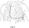
- FIG. 1is a conceptual diagram of a patient implanted with an example extravascular cardiac defibrillation system.
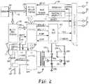
- FIG. 2is an exemplary schematic diagram of electronic circuitry within a hermetically sealed housing of a subcutaneous device according to an embodiment of the present invention.
- FIG. 3is a state diagram of detection of arrhythmias in a medical device according to an embodiment of the present invention.
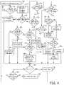
- FIG. 4is a flowchart of a method for detecting arrhythmias in a subcutaneous device according to an embodiment of the present disclosure.
- FIG. 5is a flowchart of a method of determining noise according to an embodiment of the present disclosure.
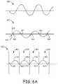
- FIG. 6 Ais a graphical representation of a determination of whether a signal is corrupted by muscle noise according to an embodiment of the present invention.
- FIG. 6 Bis a flowchart of a method of determining whether a signal is corrupted by muscle noise according to an embodiment of the present invention.
- FIG. 6 Cis a flowchart of a method of determining whether a signal is corrupted by muscle noise according to an embodiment of the present invention.
- FIG. 7is a graphical representation of a VF shock zone according to an embodiment of the present invention.
- FIGS. 8 A and 8 Bare graphical representations of the determination of whether an event is within a shock zone according to an embodiment of the present invention.
- FIG. 9is a flowchart of a method for discriminating cardiac events according to an embodiment of the disclosure.
- FIG. 10is a flowchart of a beat-based analysis during detection of arrhythmias in a medical device according to an embodiment of the present disclosure.
- FIG. 11is a flowchart of a beat-based analysis during detection of arrhythmias in a medical device according to an embodiment of the present disclosure.
- FIG. 1is a conceptual diagram of a patient 12 implanted with an example extravascular cardiac defibrillation system 10 .
- extravascular cardiac defibrillation system 10is an implanted subcutaneous ICD system.
- the techniques of this disclosuremay also be utilized with other extravascular implanted cardiac defibrillation systems, such as a cardiac defibrillation system having a lead implanted at least partially in a substernal or submuscular location.
- the techniques of this disclosuremay also be utilized with other implantable systems, such as implantable pacing systems, implantable neurostimulation systems, drug delivery systems or other systems in which leads, catheters or other components are implanted at extravascular locations within patient 12 .
- This disclosureis described in the context of an implantable extravascular cardiac defibrillation system for purposes of illustration.
- Extravascular cardiac defibrillation system 10includes an implantable cardioverter defibrillator (ICD) 14 connected to at least one implantable cardiac defibrillation lead 16 .
- ICD 14 of FIG. 1is implanted subcutaneously on the left side of patient 12 .
- Defibrillation lead 16which is connected to ICD 14 , extends medially from ICD 14 toward sternum 28 and xiphoid process 24 of patient 12 .
- defibrillation lead 16bends or turns and extends subcutaneously superior, substantially parallel to sternum 28 .
- defibrillation lead 16is implanted such that lead 16 is offset laterally to the left side of the body of sternum 28 (i.e., towards the left side of patient 12 ).
- Defibrillation lead 16is placed along sternum 28 such that a therapy vector between defibrillation electrode 18 and a second electrode (such as a housing or can 25 of ICD 14 or an electrode placed on a second lead) is substantially across the ventricle of heart 26 .
- the therapy vectormay, in one example, be viewed as a line that extends from a point on the defibrillation electrode 18 to a point on the housing or can 25 of ICD 14 .
- defibrillation lead 16may be placed along sternum 28 such that a therapy vector between defibrillation electrode 18 and the housing or can 25 of ICD 14 (or other electrode) is substantially across an atrium of heart 26 .
- extravascular ICD system 10may be used to provide atrial therapies, such as therapies to treat atrial fibrillation.
- defibrillation lead 16may be implanted such that lead 16 is offset to the right of sternum 28 or more centrally located over sternum 28 . Additionally, defibrillation lead 16 may be implanted such that it is not substantially parallel to sternum 28 , but instead offset from sternum 28 at an angle (e.g., angled lateral from sternum 28 at either the proximal or distal end).
- the distal end of defibrillation lead 16may be positioned near the second or third rib of patient 12 .
- the distal end of defibrillation lead 16may be positioned further superior or inferior depending on the location of ICD 14 , location of electrodes 18 , 20 , and 22 , or other factors.
- ICD 14is illustrated as being implanted near a midaxillary line of patient 12 , ICD 14 may also be implanted at other subcutaneous locations on patient 12 , such as further posterior on the torso toward the posterior axillary line, further anterior on the torso toward the anterior axillary line, in a pectoral region, or at other locations of patient 12 . In instances in which ICD 14 is implanted pectorally, lead 16 would follow a different path, e.g., across the upper chest area and inferior along sternum 28 .
- the extravascular ICD systemmay include a second lead including a defibrillation electrode that extends along the left side of the patient such that the defibrillation electrode of the second lead is located along the left side of the patient to function as an anode or cathode of the therapy vector of such an ICD system.
- ICD 14includes a housing or can 25 that forms a hermetic seal that protects components within ICD 14 .
- the housing 25 of ICD 14may be formed of a conductive material, such as titanium or other biocompatible conductive material or a combination of conductive and non-conductive materials.
- the housing 25 of ICD 14functions as an electrode (referred to as a housing electrode or can electrode) that is used in combination with one of electrodes 18 , 20 , or 22 to deliver a therapy to heart 26 or to sense electrical activity of heart 26 .
- ICD 14may also include a connector assembly (sometimes referred to as a connector block or header) that includes electrical feedthroughs through which electrical connections are made between conductors within defibrillation lead 16 and electronic components included within the housing.
- Housingmay enclose one or more components, including processors, memories, transmitters, receivers, sensors, sensing circuitry, therapy circuitry and other appropriate components (often referred to herein as modules).
- Defibrillation lead 16includes a lead body having a proximal end that includes a connector configured to connect to ICD 14 and a distal end that includes one or more electrodes 18 , 20 , and 22 .
- the lead body of defibrillation lead 16may be formed from a non-conductive material, including silicone, polyurethane, fluoropolymers, mixtures thereof, and other appropriate materials, and shaped to form one or more lumens within which the one or more conductors extend. However, the techniques are not limited to such constructions.
- defibrillation lead 16is illustrated as including three electrodes 18 , 20 and 22 , defibrillation lead 16 may include more or fewer electrodes.
- Defibrillation lead 16includes one or more elongated electrical conductors (not illustrated) that extend within the lead body from the connector on the proximal end of defibrillation lead 16 to electrodes 18 , 20 and 22 .
- each of the one or more elongated electrical conductors contained within the lead body of defibrillation lead 16may engage with respective ones of electrodes 18 , 20 and 22 .
- the respective conductorsmay electrically couple to circuitry, such as a therapy module or a sensing module, of ICD 14 via connections in connector assembly, including associated feedthroughs.
- the electrical conductorstransmit therapy from a therapy module within ICD 14 to one or more of electrodes 18 , 20 and 22 and transmit sensed electrical signals from one or more of electrodes 18 , 20 and 22 to the sensing module within ICD 14 .
- ICD 14may sense electrical activity of heart 26 via one or more sensing vectors that include combinations of electrodes 20 and 22 and the housing or can 25 of ICD 14 .
- ICD 14may obtain electrical signals sensed using a sensing vector between electrodes 20 and 22 , obtain electrical signals sensed using a sensing vector between electrode 20 and the conductive housing or can 25 of ICD 14 , obtain electrical signals sensed using a sensing vector between electrode 22 and the conductive housing or can 25 of ICD 14 , or a combination thereof.
- ICD 14may sense cardiac electrical signals using a sensing vector that includes defibrillation electrode 18 , such as a sensing vector between defibrillation electrode 18 and one of electrodes 20 or 22 , or a sensing vector between defibrillation electrode 18 and the housing or can 25 of ICD 14 .
- a sensing vector that includes defibrillation electrode 18such as a sensing vector between defibrillation electrode 18 and one of electrodes 20 or 22 , or a sensing vector between defibrillation electrode 18 and the housing or can 25 of ICD 14 .
- ICDmay analyze the sensed electrical signals to detect tachycardia, such as ventricular tachycardia or ventricular fibrillation, and in response to detecting tachycardia may generate and deliver an electrical therapy to heart 26 .
- ICD 14may deliver one or more defibrillation shocks via a therapy vector that includes defibrillation electrode 18 of defibrillation lead 16 and the housing or can 25 .
- Defibrillation electrode 18may, for example, be an elongated coil electrode or other type of electrode.
- ICD 14may deliver one or more pacing therapies prior to or after delivery of the defibrillation shock, such as anti-tachycardia pacing (ATP) or post shock pacing.
- ATPanti-tachycardia pacing
- ICD 14may generate and deliver pacing pulses via therapy vectors that include one or both of electrodes 20 and 22 and/or the housing or can 25 .
- Electrodes 20 and 22may comprise ring electrodes, hemispherical electrodes, coil electrodes, helix electrodes, segmented electrodes, directional electrodes, or other types of electrodes, or combination thereof. Electrodes 20 and 22 may be the same type of electrodes or different types of electrodes, although in the example of FIG. 1 both electrodes 20 and 22 are illustrated as ring electrodes.
- Defibrillation lead 16may also include an attachment feature 29 at or toward the distal end of lead 16 .
- the attachment feature 29may be a loop, link, or other attachment feature.
- attachment feature 29may be a loop formed by a suture.
- attachment feature 29may be a loop, link, ring of metal, coated metal or a polymer.
- the attachment feature 29may be formed into any of a number of shapes with uniform or varying thickness and varying dimensions. Attachment feature 29 may be integral to the lead or may be added by the user prior to implantation. Attachment feature 29 may be useful to aid in implantation of lead 16 and/or for securing lead 16 to a desired implant location.
- defibrillation lead 16may include a fixation mechanism in addition to or instead of the attachment feature. Although defibrillation lead 16 is illustrated with an attachment feature 29 , in other examples lead 16 may not include an attachment feature 29 .
- Lead 16may also include a connector at the proximal end of lead 16 , such as a DF4 connector, bifurcated connector (e.g., DF-1/IS-1 connector), or other type of connector.
- the connector at the proximal end of lead 16may include a terminal pin that couples to a port within the connector assembly of ICD 14 .
- lead 16may include an attachment feature at the proximal end of lead 16 that may be coupled to an implant tool to aid in implantation of lead 16 .
- the attachment feature at the proximal end of the leadmay separate from the connector and may be either integral to the lead or added by the user prior to implantation.
- Defibrillation lead 16may also include a suture sleeve or other fixation mechanism (not shown) located proximal to electrode 22 that is configured to fixate lead 16 near the xiphoid process or lower sternum location.
- the fixation mechanisme.g., suture sleeve or other mechanism
- the fixation mechanismmay be integral to the lead or may be added by the user prior to implantation.
- extravascular cardiac defibrillation system 10may include more than one lead.
- extravascular cardiac defibrillation system 10may include a pacing lead in addition to defibrillation lead 16 .
- defibrillation lead 16is implanted subcutaneously, e.g., between the skin and the ribs or sternum. In other instances, defibrillation lead 16 (and/or the optional pacing lead) may be implanted at other extravascular locations. In one example, defibrillation lead 16 may be implanted at least partially in a substernal location. In such a configuration, at least a portion of defibrillation lead 16 may be placed under or below the sternum in the mediastinum and, more particularly, in the anterior mediastinum. The anterior mediastinum is bounded laterally by pleurae, posteriorly by pericardium, and anteriorly by sternum 28 .
- Defibrillation lead 16may be at least partially implanted in other extra-pericardial locations, i.e., locations in the region around, but not in direct contact with, the outer surface of heart 26 .
- These other extra-pericardial locationsmay include in the mediastinum but offset from sternum 28 , in the superior mediastinum, in the middle mediastinum, in the posterior mediastinum, in the sub-xiphoid or inferior xiphoid area, near the apex of the heart, or other location not in direct contact with heart 26 and not subcutaneous.
- the leadmay be implanted at a pericardial or epicardial location outside of the heart 26 .
- FIG. 2is an exemplary schematic diagram of electronic circuitry within a hermetically sealed housing of a subcutaneous device according to an embodiment of the present invention.
- subcutaneous device 14includes a low voltage battery 153 coupled to a power supply (not shown) that supplies power to the circuitry of the subcutaneous device 14 and the pacing output capacitors to supply pacing energy in a manner well known in the art.
- the low voltage battery 153may be formed of one or two conventional LiCF x , LiMnO 2 or LiI 2 cells, for example.
- the subcutaneous device 14also includes a high voltage battery 112 that may be formed of one or two conventional LiSVO or LiMnO 2 cells. Although two both low voltage battery and a high voltage battery are shown in FIG. 2 , according to an embodiment of the present invention, the device 14 could utilize a single battery for both high and low voltage uses.
- subcutaneous device 14 functionsare controlled by means of software, firmware and hardware that cooperatively monitor the ECG signal, determine when a cardioversion-defibrillation shock or pacing is necessary, and deliver prescribed cardioversion-defibrillation and pacing therapies.
- the subcutaneous device 14may incorporate circuitry set forth in commonly assigned U.S. Pat. No.
- the cardioversion-defibrillation shock energy and capacitor charge voltagescan be intermediate to those supplied by ICDs having at least one cardioversion-defibrillation electrode in contact with the heart and most AEDs having cardioversion-defibrillation electrodes in contact with the skin.
- the typical maximum voltage necessary for ICDs using most biphasic waveformsis approximately 750 Volts with an associated maximum energy of approximately 40 Joules.
- the typical maximum voltage necessary for AEDsis approximately 2000-5000 Volts with an associated maximum energy of approximately 200-360 Joules depending upon the model and waveform used.
- the subcutaneous device 14 of the present inventionuses maximum voltages in the range of about 300 to approximately 1000 Volts and is associated with energies of approximately 25 to 150 joules or more.
- the total high voltage capacitancecould range from about 50 to about 300 microfarads.
- Such cardioversion-defibrillation shocksare only delivered when a malignant tachyarrhythmia, e.g., ventricular fibrillation is detected through processing of the far field cardiac ECG employing the detection algorithms as described herein below.
- sense amp 190in conjunction with pacer/device timing circuit 178 processes the far field ECG sense signal that is developed across a particular ECG sense vector defined by a selected pair of the subcutaneous electrodes 18 , 20 , 22 and the can or housing 25 of the device 14 , or, optionally, a virtual signal (i.e., a mathematical combination of two vectors) if selected.
- the selection of the sensing electrode pairis made through the switch matrix/MUX 191 in a manner to provide the most reliable sensing of the ECG signal of interest, which would be the R wave for patients who are believed to be at risk of ventricular fibrillation leading to sudden death.
- the far field ECG signalsare passed through the switch matrix/MUX 191 to the input of the sense amplifier 190 that, in conjunction with pacer/device timing circuit 178 , evaluates the sensed EGM. Bradycardia, or asystole, is typically determined by an escape interval timer within the pacer timing circuit 178 and/or the control circuit 144 . Pace Trigger signals are applied to the pacing pulse generator 192 generating pacing stimulation when the interval between successive R-waves exceeds the escape interval. Bradycardia pacing is often temporarily provided to maintain cardiac output after delivery of a cardioversion-defibrillation shock that may cause the heart to slowly beat as it recovers back to normal function.
- Sensing subcutaneous far field signals in the presence of noisemay be aided by the use of appropriate denial and extensible accommodation periods as described in U.S. Pat. No. 6,236,882 “Noise Rejection for Monitoring ECGs” to Lee, et al and incorporated herein by reference in its' entirety.
- Detection of a malignant tachyarrhythmiais determined in the Control circuit 144 as a function of the intervals between R-wave sense event signals that are output from the pacer/device timing 178 and sense amplifier circuit 190 to the timing and control circuit 144 . It should be noted that the present invention utilizes not only interval based signal analysis method but also supplemental sensors and morphology processing method and apparatus as described herein below.
- Supplemental sensorssuch as tissue color, tissue oxygenation, respiration, patient activity and the like may be used to contribute to the decision to apply or withhold a defibrillation therapy as described generally in U.S. Pat. No. 5,464,434 “Medical Interventional Device Responsive to Sudden Hemodynamic Change” to Alt and incorporated herein by reference in its entirety.
- Sensor processing block 194provides sensor data to microprocessor 142 via data bus 146 .
- patient activity and/or posturemay be determined by the apparatus and method as described in U.S. Pat. No. 5,593,431 “Medical Service Employing Multiple DC Accelerometers for Patient Activity and Posture Sensing and Method” to Sheldon and incorporated herein by reference in its entirety.
- Patient respirationmay be determined by the apparatus and method as described in U.S. Pat. No. 4,567,892 “Implantable Cardiac Pacemaker” to Plicchi, et al and incorporated herein by reference in its entirety.
- Patient tissue oxygenation or tissue colormay be determined by the sensor apparatus and method as described in U.S. Pat. No. 5,176,137 to Erickson, et al and incorporated herein by reference in its entirety.
- the oxygen sensor of the '137 patentmay be located in the subcutaneous device pocket or, alternatively, located on the lead 18 to enable the sensing of contacting or near-contacting tissue oxygenation or color.
- microcomputer 142including microprocessor, RAM and ROM, associated circuitry, and stored detection criteria that may be programmed into RAM via a telemetry interface (not shown) conventional in the art.
- Data and commandsare exchanged between microcomputer 142 and timing and control circuit 144 , pacer timing/amplifier circuit 178 , and high voltage output circuit 140 via a bi-directional data/control bus 146 .
- the pacer timing/amplifier circuit 178 and the control circuit 144are clocked at a slow clock rate.
- the microcomputer 142is normally asleep, but is awakened and operated by a fast clock by interrupts developed by each R-wave sense event, on receipt of a downlink telemetry programming instruction or upon delivery of cardiac pacing pulses to perform any necessary mathematical calculations, to perform tachycardia and fibrillation detection procedures, and to update the time intervals monitored and controlled by the timers in pacer/device timing circuitry 178 .
- High voltage capacitors 156 , 158 , 160 , and 162are charged to a pre-programmed voltage level by a high-voltage charging circuit 164 . It is generally considered inefficient to maintain a constant charge on the high voltage output capacitors 156 , 158 , 160 , 162 . Instead, charging is initiated when control circuit 144 issues a high voltage charge command HVCHG delivered on line 145 to high voltage charge circuit 164 and charging is controlled by means of bi-directional control/data bus 166 and a feedback signal VCAP from the HV output circuit 140 .
- High voltage output capacitors 156 , 158 , 160 and 162may be of film, aluminum electrolytic or wet tantalum construction.
- Switch circuit 114is normally open so that the positive terminal of high voltage battery 112 is disconnected from the positive power input of the high voltage charge circuit 164 .
- the high voltage charge command HVCHGis also conducted via conductor 149 to the control input of switch circuit 114 , and switch circuit 114 closes in response to connect positive high voltage battery voltage EXT B+ to the positive power input of high voltage charge circuit 164 .
- Switch circuit 114may be, for example, a field effect transistor (FET) with its source-to-drain path interrupting the EXT B+ conductor 118 and its gate receiving the HVCHG signal on conductor 145 .
- High voltage charge circuit 164is thereby rendered ready to begin charging the high voltage output capacitors 156 , 158 , 160 , and 162 with charging current from high voltage battery 112 .
- FETfield effect transistor
- High voltage output capacitors 156 , 158 , 160 , and 162may be charged to very high voltages, e.g., 300-1000V, to be discharged through the body and heart between the electrode pair of subcutaneous cardioversion-defibrillation electrodes 113 and 123 .
- the details of the voltage charging circuitryare also not deemed to be critical with regard to practicing the present invention; one high voltage charging circuit believed to be suitable for the purposes of the present invention is disclosed.
- High voltage capacitors 156 , 158 , 160 and 162may be charged, for example, by high voltage charge circuit 164 and a high frequency, high-voltage transformer 168 as described in detail in commonly assigned U.S. Pat. No.
- 4,548,209“Energy Converter for Implantable Cardioverter” to Wielders, et al. Proper charging polarities are maintained by diodes 170 , 172 , 174 and 176 interconnecting the output windings of high-voltage transformer 168 and the capacitors 156 , 158 , 160 , and 162 .
- the state of capacitor chargeis monitored by circuitry within the high voltage output circuit 140 that provides a VCAP, feedback signal indicative of the voltage to the timing and control circuit 144 .
- Timing and control circuit 144terminates the high voltage charge command HVCHG when the VCAP signal matches the programmed capacitor output voltage, i.e., the cardioversion-defibrillation peak shock voltage.
- Control circuit 144then develops first and second control signals NPULSE 1 and NPULSE 2, respectively, that are applied to the high voltage output circuit 140 for triggering the delivery of cardioverting or defibrillating shocks.
- the NPULSE 1 signaltriggers discharge of the first capacitor bank, comprising capacitors 156 and 158 .
- the NPULSE 2 signaltriggers discharge of the first capacitor bank and a second capacitor bank, comprising capacitors 160 and 162 . It is possible to select between a plurality of output pulse regimes simply by modifying the number and time order of assertion of the NPULSE 1 and NPULSE 2 signals.
- the NPULSE 1 signals and NPULSE 2 signalsmay be provided sequentially, simultaneously or individually.
- control circuitry 144serves to control operation of the high voltage output stage 140 , which delivers high energy cardioversion-defibrillation shocks between the pair of the cardioversion-defibrillation electrodes 18 and 25 coupled to the HV-1 and COMMON output as shown in FIG. 2 .
- subcutaneous device 14monitors the patient's cardiac status and initiates the delivery of a cardioversion-defibrillation shock through the cardioversion-defibrillation electrodes 18 and 25 in response to detection of a tachyarrhythmia requiring cardioversion-defibrillation.
- the high HVCHG signalcauses the high voltage battery 112 to be connected through the switch circuit 114 with the high voltage charge circuit 164 and the charging of output capacitors 156 , 158 , 160 , and 162 to commence. Charging continues until the programmed charge voltage is reflected by the VCAP signal, at which point control and timing circuit 144 sets the HVCHG signal low terminating charging and opening switch circuit 114 .
- the subcutaneous device 14can be programmed to attempt to deliver cardioversion shocks to the heart in the manners described above in timed synchrony with a detected R-wave or can be programmed or fabricated to deliver defibrillation shocks to the heart in the manners described above without attempting to synchronize the delivery to a detected R-wave.
- Episode data related to the detection of the tachyarrhythmia and delivery of the cardioversion-defibrillation shockcan be stored in RAM for uplink telemetry transmission to an external programmer as is well known in the art to facilitate in diagnosis of the patient's cardiac state.
- a patient receiving the device 14 on a prophylactic basiswould be instructed to report each such episode to the attending physician for further evaluation of the patient's condition and assessment for the need for implantation of a more sophisticated ICD.
- Subcutaneous device 14desirably includes telemetry circuit (not shown in FIG. 2 ), so that it is capable of being programmed by means of external programmer 20 via a 2-way telemetry link (not shown).
- Uplink telemetryallows device status and diagnostic/event data to be sent to external programmer 20 for review by the patient's physician.
- Downlink telemetryallows the external programmer via physician control to allow the programming of device function and the optimization of the detection and therapy for a specific patient.
- Programmers and telemetry systems suitable for use in the practice of the present inventionhave been well known for many years.
- Known programmerstypically communicate with an implanted device via a bi-directional radio-frequency telemetry link, so that the programmer can transmit control commands and operational parameter values to be received by the implanted device, so that the implanted device can communicate diagnostic and operational data to the programmer.
- Programmers believed to be suitable for the purposes of practicing the present inventioninclude the Models 9790 and CareLink® programmers, commercially available from Medtronic, Inc., Minneapolis, Minn.
- “Quality”is defined as the signal's ability to provide accurate heart rate estimation and accurate morphological waveform separation between the patient's usual sinus rhythm and the patient's ventricular tachyarrhythmia.
- Appropriate indicesmay include R-wave amplitude, R-wave peak amplitude to waveform amplitude between R-waves (i.e., signal to noise ratio), low slope content, relative high versus low frequency power, mean frequency estimation, probability density function, or some combination of these metrics.
- Automatic vector selectionmight be done at implantation or periodically (daily, weekly, monthly) or both.
- automatic vector selectionmay be initiated as part of an automatic device turn-on procedure that performs such activities as measure lead impedances and battery voltages.
- the device turn-on proceduremay be initiated by the implanting physician (e.g., by pressing a programmer button) or, alternatively, may be initiated automatically upon automatic detection of device/lead implantation.
- the turn-on proceduremay also use the automatic vector selection criteria to determine if ECG vector quality is adequate for the current patient and for the device and lead position, prior to suturing the subcutaneous device 14 device in place and closing the incision.
- the preferred ECG vector or vectorsmay also be selected at implant as part of the device turn-on procedure.
- the preferred vectorsmight be those vectors with the indices that maximize rate estimation and detection accuracy.
- the ECG signal quality metricmay be measured on the range of vectors (or alternatively, a subset) as often as desired. Data may be gathered, for example, on a minute, hourly, daily, weekly or monthly basis. More frequent measurements (e.g., every minute) may be averaged over time and used to select vectors based upon susceptibility of vectors to occasional noise, motion noise, or EMI, for example.
- the subcutaneous device 14may have an indicator/sensor of patient activity (piezo-resistive, accelerometer, impedance, or the like) and delay automatic vector measurement during periods of moderate or high patient activity to periods of minimal to no activity.
- an indicator/sensor of patient activitypiezo-resistive, accelerometer, impedance, or the like
- One representative scenariomay include testing/evaluating ECG vectors once daily or weekly while the patient has been determined to be asleep (using an internal clock (e.g., 2:00 am) or, alternatively, infer sleep by determining the patient's position (via a 2- or 3-axis accelerometer) and a lack of activity).
- noisee.g., muscle, motion, EMI, etc.
- Subcutaneous device 14may optionally have an indicator of the patient's posture (via a 2- or 3-axis accelerometer).
- This sensormay be used to ensure that the differences in ECG quality are not simply a result of changing posture/position.
- the sensormay be used to gather data in a number of postures so that ECG quality may be averaged over these postures or, alternatively, selected for a preferred posture.
- vector quality metric calculationswould occur a number of times over approximately 1 minute, once per day, for each vector. These values would be averaged for each vector over the course of one week. Averaging may consist of a moving average or recursive average depending on time weighting and memory considerations. In this example, the preferred vector(s) would be selected once per week.
- FIG. 3is a state diagram of detection of arrhythmias in a medical device according to an embodiment of the present invention.
- the device 14is in a not concerned state 302 , during which R-wave intervals are being evaluated to identify periods of rapid rates and/or the presence of asystole.
- the device 14transitions from the not concerned state 302 to a concerned state 304 .
- the device 14evaluates a predetermined window of ECG signals to determine the likelihood that the signal is corrupted with noise and to discriminate rhythms requiring shock therapy from those that do not require shock therapy, using a combination of R-wave intervals and ECG signal morphology information.
- the device 14transitions from the concerned state 304 to an armed state 306 . If a rhythm requiring shock therapy is no longer detected while the device is in the concerned state 304 and the R-wave intervals are determined to no longer be short, the device 14 returns to the not concerned state 302 . However, if a rhythm requiring shock therapy is no longer detected while the device is in the concerned state 304 , but the R-wave intervals continue to be detected as being short, processing continues in the concerned state 304 .
- the device 14charges the high voltage shocking capacitors and continues to monitor R-wave intervals and ECG signal morphology for spontaneous termination. If spontaneous termination of the rhythm requiring shock therapy occurs, the device 14 returns to the not concerned state 302 . If the rhythm requiring shock therapy is still determined to be occurring once the charging of the capacitors is completed, the device 14 transitions from the armed state 306 to a shock state 308 . In the shock state 308 , the device 14 delivers a shock and returns to the armed state 306 to evaluate the success of the therapy delivered.
- the transitioning between the not concerned state 302 , the concerned state 304 , the armed state 306 and the shock state 308may be performed as described in detail in U.S. Pat. No. 7,894,894 to Stadler et al., incorporated herein by reference in it's entirety.
- FIG. 4is a flowchart of a method for detecting arrhythmias in a subcutaneous device according to an embodiment of the present disclosure.
- device 14continuously evaluates the two channels ECG1 and ECG2 associated with two predetermined electrode vectors to determine when sensed events occur.
- the electrode vectors for the two channels ECG1 and ECG2may include a first vector (ECG1) selected between electrode 20 positioned on lead 16 and the housing or can 25 of ICD 14 , while the other electrode vector (ECG 2) is a vertical electrode vector between electrode 20 and electrode 22 positioned along the lead 16 .
- the two sensing channelsmay in any combination of possible vectors, including those formed by the electrodes shown in FIG. 2 , or other additional electrodes (not shown) that may be included along the lead or positioned along the housing of ICD 14 .
- the device 14determines whether to transition from the not concerned state 302 to the concerned state 304 by determining a heart rate estimate in response to the sensing of R-waves, as described in U.S. Pat. No. 7,894,894 to Stadler et al., incorporated herein by reference in it's entirety.
- Block 305Upon transition from the not concerned state to the concerned state, Block 305 , a most recent window of ECG data from both channels ECG1 and ECG2 are utilized, such as three seconds, for example, so that processing is triggered in the concerned state 304 by a three-second timeout, rather than by the sensing of an R-wave, which is utilized when in the not concerned state 302 . It is understood that while the processing is described as being triggered over a three second period, other times periods for the processing time utilized when in the concerned state 304 may be chosen, but should preferably be within a range of 0.5 to 10 seconds.
- the present inventiondetermines how sinusoidal and how noisy the signals are in order to determine the likelihood that a ventricular fibrillation (VF) or fast ventricular tachycardia (VT) event is taking place, since the more sinusoidal and low noise the signal is, the more likely a VT/VF event is taking place.
- Block 305a buffer for each of the two channels ECG 1 and ECG2 for storing classifications of 3-second segments of data as “shockable” or “non-shockable” is cleared. Processing of signals of the two channels ECG1 and ECG2 while in the concerned state 304 is then triggered by the three second time period, rather than by the sensing of an R-wave utilized during the not concerned state 302 .
- morphology characteristics of the signal during the three second time interval for each channelare utilized to determine whether the signals are likely corrupted by noise artifacts and to characterize the morphology of the signal as “shockable” or “not shockable”. For example, using the signals associated with the three second time interval, a determination is made for each channel ECG1 and ECG 2 as to whether the channel is likely corrupted by noise, Block 342 , and a determination is then made as to whether both channels ECG1 and ECG2 are corrupted by noise, Block 344 .
- FIG. 5is a flowchart of a method of determining noise according to an embodiment of the present disclosure.
- the determination as to whether the signal associated with each of the channels ECG1 and ECG2 is likely corrupted by noise, Block 342 of FIG. 4includes multiple sequential noise tests that are performed on each channel ECG and ECG2.
- a first noise testfor example, a determination is made as to whether a metric of signal energy content of the signal for the channel is within predetermined limits, Block 380 .
- the mean rectified amplitudeis calculated, a determination is made as to whether the mean rectified amplitude is between an upper average amplitude limit and a lower average amplitude limit, the lower average amplitude limit being associated with asystole episodes without artifact and the upper average amplitude limit being associated with a value greater than what would be associated with ventricular tachycardia and ventricular fibrillation events.
- the upper average amplitude limitis set as 1.5 mV
- the lower average amplitude limitis set as 0.013 mV. While the metric of signal energy content is described above as the mean rectified amplitude, it is understood that other signal of energy contents could be utilized.
- the three second segment for that channelis identified as being likely corrupted with noise, Block 386 , and no further noise tests are initiated for that channel's segment.
- a noise to signal ratiois calculated and a determination is made as to whether the noise to signal ratio is less than a predetermined noise to signal threshold, Block 382 .
- the amplitude of each sample associated with the three second windowis determined, resulting in N raw sample amplitudes.
- the raw signalis lowpass filtered, resulting in L lowpass sample amplitudes.
- the raw mean rectified amplitudeis determined as the average of the absolute values of the raw sample amplitudes.
- the lowpass mean rectified amplitudeis determined as the average of the absolute values of the lowpass sample amplitudes.
- a highpass mean rectified amplitudeis then calculated as the difference between the raw mean rectified amplitude and the lowpass mean rectified amplitude.
- the noise to signal ratiois then determined as the ratio of the highpass mean rectified amplitude to the lowpass mean rectified amplitude. If the noise to signal ratio is greater than a predetermined threshold, such as 0.0703, for example, the three second segment for that channel is identified as being likely corrupted with noise, Block 386 , and no further noise tests are initiated for the segment.
- the determination as to whether the signal is corrupted by muscle noiseis made by determining whether the signal includes a predetermined number of signal inflections indicative of the likelihood of the signal being corrupted by muscle noise, using a muscle noise pulse count that is calculated to quantify the number of signal inflections in the three second interval for each channel ECG1 and ECG2. The presence of a significant number of inflections is likely indicative of muscle noise.
- FIG. 6 Ais a graphical representation of a determination of whether a signal is corrupted by muscle noise according to an embodiment of the present invention.
- FIG. 6 Bis a flowchart of a method of determining whether a signal is corrupted by muscle noise according to an embodiment of the present invention.
- the raw signal 420is applied to a first order derivative filter to obtain a derivative signal 422 , and all of the zero-crossings 424 in the derivative signal 422 are located, Block 460 .
- a data pair corresponding to the data points immediately prior to and subsequent to the zero crossings 424 , points 426 and 428 respectively, for each crossingis obtained.
- the value of the data point in each data pair with smaller absolute valueis zeroed in order to allow a clear demarcation of each pulse when a rectified signal 430 is derived from the derivative signal 422 with zeroed zero-crossing points 432 .
- a pulse amplitude threshold Tdfor determining whether the identified inflection is of a significant amplitude to be identified as being associated with muscle noise, is determined, Block 462 , by dividing the rectified signal from the three second segment into equal sub-segments 434 , estimating a local maximum amplitude 436 - 442 for each of the sub-segments 434 , and determining whether the local amplitudes 436 - 442 are less than a portion of the maximum amplitude, which is maximum amplitude 440 in the example of FIG. 6 A , for the whole three second segment. If the local maximum amplitude is less than the portion of the maximum amplitude for the whole three second segment, the local maximum amplitude is replaced by the maximum for the whole three second segment for the sub-segment corresponding to that local maximum amplitude.
- each of the sub-segments 434which have a length of approximately 750 milliseconds, will contain many inflections, such as every 25 milliseconds, for example.
- the three second segmentis divided into four sub-segments and the local maximum amplitudes are replaced by the maximum amplitude for the whole segment if the local maximum amplitude is less than one fifth of the maximum amplitude for the whole segment.
- the pulse amplitude threshold Td for the segmentis set equal to a predetermined fraction of the mean of the local maximum amplitudes for each of the sub-segments.
- the pulse amplitude threshold Td for the three second segmentis set equal to one sixth of the mean of the local maximum amplitudes 436 - 440 .
- the inflections associated with the signal for the three second segmentis classified as being of significant level to be likely indicative of noise by determining whether the pulse amplitude threshold Td is less than a pulse threshold, Block 464 .
- the pulse thresholdis set as 1 microvolt. If the pulse amplitude threshold Td is less than the pulse threshold, the signal strength is too small for a determination of muscle noise, and therefore the signal is determined to be not likely corrupted by noise and therefore the channel is determined to be not noise corrupted, Block 466 .
- the three second segmentis divided into twelve sub-segments of 250 ms window length, the number of muscle noise pulses in each sub-segment is counted, and both the sub-segment having the maximum number of muscle noise pulses and the number of sub-segments having 6 or more muscle noise pulses that are greater than a predetermined minimum threshold is determined.
- Muscle noiseis determined to be present in the signal if either the maximum number of muscle noise pulses in a single sub-segment is greater than a noise pulse number threshold or the number of sub-segments of the twelve sub-segments having 6 or more muscle noise pulses greater than the minimum threshold is greater than or equal to a sub-segment pulse count threshold.
- the noise pulse number thresholdis set equal to eight and the sub-segment pulse count threshold is set equal to three.
- the pulse amplitude threshold Tdis greater than or equal to the pulse threshold, No in Block 464 , the maximum number of muscle noise counts in a single sub-segment is determined, Block 468 . If the maximum number of muscle noise counts is greater than the noise pulse number threshold, Yes in Block 470 , the channel is determined to be noise corrupted, Block 472 .
- the maximum number of muscle noise counts for the channelis less than or equal to the noise pulse number threshold, No in Block 470 , the number of sub-segments of the twelve sub-segments having 6 or more muscle noise pulses greater than the minimum threshold is determined, Block 474 , and if the number is greater than or equal to a sub-segment pulse count threshold, Yes in Block 476 , the channel is determined to be noise corrupted, Block 472 . If the number is less than the sub-segment pulse count threshold, No in Block 476 , the channel is determined not to be noise corrupted, Block 466 .
- FIG. 6 Cis a flowchart of a method of determining whether a signal is corrupted by muscle noise according to an embodiment of the present invention. Since muscle noise can be present during an episode of ventricular tachycardia, the width of the overall signal pulse waveform is determined in order to distinguish between signals that are determined likely to be purely noise related and signals that are both shockable events and determined to include noise. Therefore, as illustrated in FIG. 6 C , according to an embodiment of the present invention, once muscle noise is determined to be present as a result of the muscle noise pulse count being satisfied, No in Block 470 and Yes in Block 476 , a determination is made as to whether the signal is both noise corrupted and shockable, Block 480 .
- the determination in Block 480 as to whether the signal is both noisy and shockableis made, for example, by dividing the rectified signal, having 768 data points, into four sub-segments and determining a maximum amplitude for each of the four sub-segments by determining whether a maximum amplitude for the sub-segment is less than a portion of the maximum amplitude for the entire rectified signal in the three second segment. For example, a determination is made for each sub-segment as to whether the maximum amplitude for the sub-segment is less than one fourth of the maximum amplitude for the entire rectified signal. If less than a portion of the maximum amplitude for the entire rectified signal in the three second segment, the maximum amplitude for the sub-segment is set equal to the maximum amplitude for the entire rectified signal.
- a mean rectified amplitude for each of the sub-segmentsis determined by dividing the sum of the rectified amplitudes for the sub-segment by the number of samples in the sub-segment, i.e., 768 ⁇ 4. Then the normalized mean rectified amplitude for each sub-segment is determined by dividing the mean rectified amplitude for each of the sub-segments by the peak amplitude for the sub-segment. The normalized mean rectified amplitude for the three second segment is then determined as the sum of the normalized mean rectified amplitudes for each sub-segment divided by the number of sub-segments, i.e., four.
- Block 480based on whether the normalized mean rectified amplitude for the three second segment is greater than a predetermined threshold for identifying signals that, despite being indicative of a likelihood of being associated with noise, nevertheless are associated with a shockable event. For example, according to an embodiment of the present invention, a determination is made as to whether the normalized mean rectified amplitude for the three second segment is greater than 18 microvolts. If the normalized mean rectified amplitude for the three second segment is less than or equal to the predetermined threshold, the channel is likely corrupted by muscle noise and not shockable, No in Block 480 , and is therefore identified as being corrupted by noise, Block 472 .
- the channelis determined to be likely corrupted by muscle noise and shockable, Yes in Block 480 , and is therefore identified as not to be likely corrupted by muscle noise, Block 478 .
- the mean frequency of the signal during the 3 second segment for each channel ECG 1 and ECG2is generated, for example, by calculating the ratio of the mean absolute amplitude of the first derivative of the 3 second segment to the mean absolute amplitude of the 3 second segment, multiplied by a constant scaling factor. If the mean frequency is determined to be greater than or equal to the predetermined mean frequency threshold, No in Block 388 , the three second segment for that channel is identified as being likely corrupted with noise, Block 386 . If the mean frequency is determined to be less than the predetermined mean frequency threshold, Yes in Block 388 , the three second segment for that channel is identified as being not noise corrupted, Block 390 .
- the determination in Block 388includes determining whether the mean frequency is less than a predetermined upper mean frequency threshold, such as 11 Hz (i.e., mean period T of approximately 91 milliseconds) for example, and whether the mean frequency is less than a predetermined lower mean frequency, such as 3 Hz for example. If the mean frequency is below a second, lower threshold, such as 3 Hz, for example, the signal is also rejected as noise and no further noise tests are initiated.
- a predetermined upper mean frequency thresholdsuch as 11 Hz (i.e., mean period T of approximately 91 milliseconds) for example, and whether the mean frequency is less than a predetermined lower mean frequency, such as 3 Hz for example. If the mean frequency is below a second, lower threshold, such as 3 Hz, for example, the signal is also rejected as noise and no further noise tests are initiated.
- This comparison of the mean frequency to a second lower thresholdis intended to identify instances of oversensing, resulting in appropriate transition to the concerned state. If the mean frequency of the signal is less than 3 Hz, it is generally not possible for the heart rate to be greater than 180 beats per minute. In practice, it may be advantageous to set the lower frequency threshold equal to the programmed VT/VF detection rate, which is typically approximately 3 Hz.
- Block 388if the mean frequency is determined to be either greater than or equal to the predetermined upper mean frequency threshold or less than the lower threshold, the three second segment for that channel is identified as being likely corrupted with noise, Block 386 . If the mean frequency is determined to be both less than the predetermined upper mean frequency threshold and greater than the lower threshold, the three second segment for that channel is identified as not being noise corrupted, Block 390 .
- Block 342a determination is made as to whether both channels are determined to be noise corrupted, Block 344 . If the signal associated with both channels ECG1 and ECG2 is determined to likely be corrupted by noise, both channels are classified as being not shockable, Block 347 , and therefore a buffer for each channel ECG1 and ECG 2 containing the last three classifications of the channel is updated accordingly and the process is repeated for the next three-second windows.
- the devicedistinguishes between either one of the channels being not corrupted by noise or both channels being not corrupted by noise by determining whether noise was determined to be likely in only one of the two channels ECG1 and ECG2, Block 346 .
- Block 346If noise was not likely for both of the channels, No in Block 346 , i.e., both channels are determined to be clean channels, a determination is made whether the signal for both channels is more likely associated with a VT event or with a VF event by determining whether the signal for both channels includes R-R intervals that are regular and can be therefore classified as being relatively stable, Block 356 .
- the determination in Block 356 of whether the R-R intervals are determined to be relatively stablemay be made using the method described in U.S. Pat. No. 7,894,894 to Stadler et al., incorporated herein by reference in it's entirety.
- the signal for both channelsis identified as likely being associated with VF, which is then verified by determining whether the signal for each channel is in a VF shock zone, Block 360 , described below. If R-R intervals for both channels are determined to be stable, YES in Block 356 , the signal is identified as likely being associated with VT, which is then verified by determining, based on both channels, whether the signal is in a VT shock zone, Block 358 .
- FIG. 7is a graphical representation of a VF shock zone according to an embodiment of the present invention.
- a VF shock zone 500is defined for each channel ECG1 and ECG2 based on the relationship between the calculated low slope content and the spectral width associated with the channel.
- the low slope content metricis calculated as the ratio of the number of data points with low slope to the total number of samples in the 3-second segment.
- the difference between successive ECG samplesis determined as an approximation of the first derivative (i.e, the slope) of the ECG signal.
- the raw signal for each channelis applied to a first order derivative filter to obtain a derivative signal for the three-second segment.
- the derivative signalis then rectified, divided into four equal sub-segments, and the largest absolute slope is estimated for each of the four sub-segments.
- the average of the four slopesis calculated and divided by a predetermined factor, such as 16 for example, to obtain a low slope threshold.
- the low slope contentis then obtained by determining the number of sample points in the three-second segment having an absolute slope less than or equal to the low slope threshold.
- the low slope thresholdis a fraction, rather than a whole number
- a correctionis made to the low slope content to add a corresponding fraction of the samples. For example, if the threshold is determined to be 4.5, then the low slope content is the number of sample points having an absolute slope less than or equal to 4 plus one half of the number of sample points with slope equal to 5.
- the spectral width metricwhich corresponds to an estimate of the spectral width of the signal for the three-second segment associated with each channel ECG1 and ECG2, is defined, for example, as the difference between the mean frequency and the fundamental frequency of the signal.
- the spectral width metricis calculated by determining the difference between the most recent estimate of the RR-cycle length and the mean spectral period of the signal for that channel.
- the mean spectral periodis the inverse of the mean spectral frequency.
- noise 506tends to have a relatively higher spectral width
- normal sinus rhythm 508tends to have a relatively higher low slope content relative to VF
- both noise 506 and normal sinus rhythm 508would be located outside the VF shock zone 500 .
- the eventis determined to be associated with VF, i.e., the intervals for both channels are determined to be irregular
- a determination is made that channel ECG1 is in the VF shock zone, Yes in Block 360if, for channel ECG1, both the low slope content is less than the first boundary 502 and the spectral width is less than the second boundary 504 .
- the three second segment for that channel ECG1is then determined to be shockable, Block 363 and the associated buffer for that channel is updated accordingly. If either the low slope content for the channel is not less than the first boundary 502 or the spectral width is not less than the second boundary, the channel ECG1 is determined not to be in the VF shock zone, No in Block 360 , the three second segment for that channel ECG1 is then determined to be not shockable, Block 365 , and the associated buffer is updated accordingly.
- channel ECG2is in the VF shock zone, Yes in Block 362 , if, for channel ECG2, both the low slope content is less than the first boundary 502 and the spectral width is less than the second boundary 504 .
- the three second segment for that channel ECG2is then determined to be shockable, Block 369 and the associated buffer for that channel is updated accordingly. If either the low slope content for the channel is not less than the first boundary 502 or the spectral width is not less than the second boundary, the channel ECG2 is determined not to be in the VF shock zone, No in Block 362 , the three second segment for that channel ECG2 is then determined to be not shockable, Block 367 , and the associated buffer is updated accordingly.
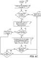
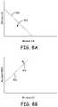
- FIGS. 8 A and 8 Bare graphical representations of the determination of whether an event is within a shock zone according to an embodiment of the present invention.
- the low slope content and the spectral widthis determined for each channel ECG1 and ECG2, as described above in reference to determining the VF shock zone.
- a determinationis made as to which channel of the two signal channels ECG1 and ECG2 contains the minimum low slope content and which channel of the two signal channels ECG 1 and ECG2 contains the minimum spectral width.
- a first VT shock zone 520is defined based on the relationship between the low slope content associated with the channel determined to have the minimum low slope content and the spectral width associated with the channel determined to have the minimum spectral width.
- a second VT shock zone 524is defined based on the relationship between the low slope content associated with the channel determined to have the minimum low slope content and the normalized mean rectified amplitude associated with the channel determined to have the maximum normalized mean rectified amplitude.
- both the minimum low slope countis less than the first boundary 522 , i.e., ⁇ 0.004 ⁇ minimum spectral width+0.93, and the maximum normalized mean rectified amplitude is greater than the second boundary 526 , i.e., 68 ⁇ minimum low slope count+8.16, the event is determined to be in the VT shock zone, YES in Block 358 , and both channels ECG1 and ECG2 are determined to be shockable, Block 357 , and the associated buffers are updated accordingly.
- the eventis determined to be outside the VT shock zone, NO in Block 358 , and both channels ECG1 and ECG2 are determined to be not shockable, Block 359 .
- the test results for each channel ECG1 and ECG2 as being classified as shockable or not shockableare stored in a rolling buffer containing the most recent eight such designations, for example, for each of the two channels ECG1 and ECG2 that is utilized in the determination of Block 356 , as described below.
- Block 346a determination is made whether the signal for the channel not corrupted by noise, i.e., the “clean channel”, is more likely associated with a VT event or with a VF event by determining whether the signal for the clean channel includes R-R intervals that are regular and can be therefore classified as being relatively stable, Block 348 . If the R-R intervals are determined not to be relatively stable, NO in Block 348 , the signal for the clean channel is identified as likely being associated with VF, which is then verified by determining whether the signal for the clean channel is in a VF shock zone, Block 350 , described below.
- the signalis identified as likely being associated with VT, which is then verified by determining whether the signal for the clean channel is in a VT shock zone, Block 352 .
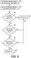
- FIG. 9is a flowchart of a method for discriminating cardiac events according to an embodiment of the disclosure. For example, as illustrated in FIG. 9 , predetermined maximum and minimum intervals for the clean channel are identified from the updated buffer of 12 RR-intervals, Block 342 of FIG. 4 . According to an embodiment of the present invention, the largest RR-interval and the sixth largest RR-interval of the twelve RR-intervals are utilized as the maximum interval and the minimum interval, respectively.
- the difference between the maximum RR-interval and the minimum RR-interval of the 12 RR-intervalsis calculated to generate an interval difference associated with the clean channel, 702 .
- a determinationis then made as to whether the interval difference is greater than a predetermined stability threshold, Block 704 , such as 110 milliseconds, for example.
- the eventis classified as an unstable event, Block 706 , and therefore the clean channel is determined not to include regular intervals, No in Block 348 , and a determination is made as to whether the signal associated with the clean channel is within a predetermined VF shock zone, Block 350 of FIG. 4 , described below. If the interval difference is less than or equal to the stability threshold, No in Block 704 , the device determines whether the minimum RR interval is greater than a minimum interval threshold, Block 710 , such as 200 milliseconds, for example.
- a minimum interval thresholdBlock 710 , such as 200 milliseconds, for example.
- the devicedetermines whether the maximum interval is less than or equal to a maximum interval threshold, Block 712 , such as 333 milliseconds for example.
- the eventis classified as an unstable event, Block 706 , and therefore the clean channel is determined not to include regular intervals, No in Block 348 , and a determination is made as to whether the signal associated with the clean channel is within a predetermined VF shock zone, Block 350 of FIG. 4 , described below. If the maximum interval is less than or equal to the maximum interval threshold, the event is classified as a stable event, Block 714 , and therefore the clean channel is determined to include regular intervals, Yes in Block 348 , and a determination is made as to whether the signal associated with the clean channel is within a predetermined VT shock zone, Block 352 of FIG. 4 , described below.
- the determination of whether the clean channel is within the VF shock zone, Block 350is made based upon a low slope content metric and a spectral width metric, similar to the VF shock zone determination described above in reference to Blocks 360 and 362 , both of which are determined for the clean channel using the method described above.
- the determination of whether the clean channel is in the VF shock zoneis made using Equations 1 and 2, so that if either the low slope content for the clean channel is not less than the first boundary 502 or the spectral width is not less than the second boundary 504 , the clean channel is determined not to be in the VF zone, No in Block 350 and both channels are classified as not shockable, Block 351 , and the associated buffers are updated accordingly.
- the clean channelis determined to be in the VF zone, Yes in Block 350 .
- a determinationis then made as to whether the channel determined to be corrupted by noise, i.e., the “noisy channel”, is within the VF shock zone, Block 354 . If either the low slope content for the noisy channel is not less than the first boundary 502 or the spectral width is not less than the second boundary 504 , the noisy channel is determined not to be in the VF zone, No in Block 354 , the clean channel is classified as shockable and the noisy channel is classified as not shockable, Block 355 , and the associated buffers are updated accordingly.
- the noisy channelis determined to be in the VF zone, Yes in Block 354 , both the clean channel and the noisy channel are classified as being shockable, Block 353 , and the associated buffers are updated accordingly.
- the low slope content and the spectral widthis determined for the clean channel as described above in reference to determining the VF shock zone.
- the first VT shock zone 520is defined based on the relationship between the low slope content and the spectral width associated with the clean channel according to Equation 3, for example, and the second VT shock zone 524 is defined based on the relationship between the low slope count and the normalized mean rectified amplitude associated with the clean channel.
- the normalized mean rectified amplitudes for the clean channelis the same as described above in reference to the noise detection tests of Block 344 .
- the second VT shock zone 524is defined by a second boundary 526 associated with the relationship between the low slope count and the normalized mean rectified amplitude of the clean channel using Equation 4.
- both the low slope countis less than the first boundary 522 , i.e., ⁇ 0.004 ⁇ spectral width of clean channel+0.93, and the normalized mean rectified amplitude is greater than the second boundary 526 , i.e., 68 ⁇ low slope count of clean channel+8.16, the clean channel is determined to be in the VT shock zone, Yes in Block 352 , both channels are classified as being shockable, Block 353 , and the associated buffers are updated accordingly.
- the clean channelis determined to be outside the VT shock zone, No in Block 352 , both channels are classified as being not shockable, Block 351 , and the associated buffers are updated accordingly.
- the devicein addition to the classification of the sensing channels ECG1 and ECG2 as being shockable or not shockable using a gross morphology analysis, as described in FIG. 4 , for example, the device also performs a beat-based analysis of the beats within each of the three-second windows, Block 368 , so that the decision on state transitions (e.g.
- the devicedetermines whether a predetermined number, such as two out of three for example, of three-second segments for both channels ECG1 and ECG2 have been classified as being shockable during the gross morphology analysis, Blocks 353 , 357 , 363 and 369 , and determines whether those three-second segments for both channels have also been classified as being shockable during the beat-based analysis, Block 368 .
- a predetermined numbersuch as two out of three for example, of three-second segments for both channels ECG1 and ECG2 have been classified as being shockable during the gross morphology analysis, Blocks 353 , 357 , 363 and 369 , and determines whether those three-second segments for both channels have also been classified as being shockable during the beat-based analysis, Block 368 .
- the devicetransitions from the concerned state 304 to the armed state 306 , Yes in Block 370 .
- processingcontinues to be triggered by a three-second time out as is utilized during the concerned state 304 , described above.
- the devicedoes not transition from the concerned state 304 to the armed state 306 , No in Block 370 , and a determination as to whether to transition back to the not concerned state 302 is made, Block 372 .
- the determination as to whether to transition from the concerned state 304 back to the not concerned state 302is made, for example, by determining whether a heart rate estimate is less than a heart rate threshold level in both of the two channels ECG1 and ECG2, using the method for determining a heart rate estimate as described in U.S. Pat. No.
- Blocks 353 , 355 , 357 , and 363 - 369is performed by analyzing the gross morphology of a sensed waveform occurring within the three-second windows.
- the ECG signalis segmented into n-second intervals, i.e., 3 second intervals, that are used for determining gross morphology features of the three-second waveform.
- the gross morphology featuresare determined across an n-second time interval without relying on R-wave sensing and are therefore features making up the whole waveform signal that can be determined from the ECG signal independent of individual cardiac signals of the cardiac cycle, i.e., individual beats or R-waves contained within the three-second window that are within the entire three-second window.
- a single waveform in the n-second windowbegins at the start of the window, extends through entire window, ending at the end of the three-second window so that a single morphology determination is made for the single waveform included within the single three-second window.
- n-second windowmay start and end at any time point relative to each of the individual R-wave signals irrespective of where an individual R-wave signal starts and ends, so that multiple individual beat-based determinations are made for the multiple beat waveforms included within the single three-second window.
- Morphology features computed for the single waveform extending across the n-second time periodare referred to as “gross” morphology features because the features are characteristics of the single signal, extending from the start to the end of the window, that is extracted, independent of cardiac cycle timing, from a time segment that includes multiple individual cardiac cycles.
- morphology features extracted from the ECG signal during a cardiac cycleare referred to as “beat-based” features.
- Beat-based featuresare determined from an ECG signal segment over a time interval of one cardiac cycle of multiple cardiac cycles contained within a single three-second window. Beat-based features may be averaged or determined from multiple cardiac cycles but are representative of a single feature of the ECG signal during a cardiac cycle. Determination of a beat feature is dependent on identifying the timing of a cardiac cycle, or at least a sensed event such as an R-wave, as opposed to determining gross features independent of the cardiac cycle over a time segment that is typically longer than one cardiac cycle.
- FIG. 10is a flowchart of a beat-based analysis during detection of arrhythmias in a medical device according to an embodiment of the present disclosure. Therefore, as described above, in addition to performing the morphology analysis of the whole waveform within the three-second windows associated with each sensing channel ECG1 and ECG2, the device performs a beat-based analysis of the signal sensed simultaneously within both channels ECG1 and ECG2, Block 368 . In particular, as illustrated in FIG.
- the devicelocates a beat, i.e., R-wave, Block 800 , and compares the individual beat to a predetermined beat template, Block 802 , such as a normal sinus rhythm template, for example. Based upon the comparison of the beat to the template, the device determines whether the beat is either a match beat or a non-match beat by determining the extent to which the beat matches the template, Block 804 . For example, in order to identify the beat as either a match beat or a non-match beat, the device determines in Block 804 whether the beat matches the sinus rhythm template within a predetermined percentage, such as 60 percent, for example.
- a predetermined beat templatesuch as a normal sinus rhythm template
- Block 804If the beat matches the template by the predetermined percentage or greater, Yes in Block 804 , the beat is identified as a match beat and the number of match beats for the three-second window is updated, Block 806 . If the beat matches the template by less than the predetermined percentage, No in Block 804 , the beat is identified as a non-match beat and the number of non-match beats for the three-second window is updated, Block 808 .
- the devicedetermines whether the match/non-match determination has been made for all of the beats in the three-second window, Block 810 . If the determination has not been made for all of the beats in the three-second window, No in Block 810 , the process is repeated with another beat located within the three-second window. Once the determination has been made for all of the beats in the three-second window, Yes in Block 810 , a determination is made as to whether the number of non-match beats in the three-second window is greater than a non-match threshold, Block 812 .
- the non-match thresholdis set as a predetermined percentage, such as 75 percent for example, so that if the number of individual beats in the three-second window that are identified as being non-match beats is greater than 75 percent of the number of all of the beats in the window, Yes in Block 812 , the three-second window is identified as being shockable based on beat-based analysis, Block 814 . On the other hand, if the number of individual beats in the three-second window that are identified as being non-match beats is not greater than 75 percent of the number of all of the beats in the window, No in Block 812 , the three-second window is identified as being not shockable based on beat based analysis, Block 814 .
- a predetermined percentagesuch as 75 percent for example
- Block 816The beat-based analysis determination of the three-second windows as being shockable 814 or not shockable, Block 816 is then used in combination with the waveform morphology analysis of both of the three-second windows being shockable, Blocks 353 , 357 , 363 and 369 or both not shockable, Blocks 351 , 355 , 359 , 365 and 367 to determine whether to transition to the next state, Block 370 , as described above.
- both channels ECG1 and ECG2could have been determined to be shockable can vary. First, if noise was not determined to be occurring in either channel, No in Block 346 , but both channels are determined to have regular intervals, Yes in Block 356 , and both channels are determined to be in the VT shock zone, Yes in Block 358 , both of the sensing channels ECG1 and ECG2 are determined to be shockable, Block 359 .
- both channelsare not determined to have regular intervals, No in Block 356 , and both channels are determined to be in the VF shock zone, Yes in Blocks 360 and 362 , both of the sensing channels ECG1 and ECG2 are determined to be shockable.
- both of the sensing channels ECG1 and ECG2are determined to be shockable, Block 353 .
- the clean channelwas determined not to have regular intervals, No in Block 348 , and both the clean and the noisy channel are determined to be in the VF shock zone, Yes in Blocks 350 and 354 , both of the sensing channels ECG1 and ECG2 are determined to be shockable, Block 353 .
- both channelsmay be determined to be shockable based on a determination that both channels are either in the VF shock zone, Blocks 363 and 369 , or Block 353 via Blocks 350 and 354 , based on a determination that both channels are in the VT shock zone, Block 357 , or based on a determination that only one channel, i.e., the clean channel, is within the VT shock zone, Block 353 via Block 352 .
- FIG. 11is a flowchart of a beat-based analysis during detection of arrhythmias in a medical device according to an embodiment of the present disclosure. Therefore, according to an embodiment of the present disclosure, the device may initially identify how the three-second windows were determined to be shockable during the gross morphology analysis, i.e., by using both channels or only one channel, and based on this determination, determine which channels that are to be utilized in the beat morphology analysis.
- the devicedetermines whether both channels were used in the identification of both channels being shockable, Block 820 , so that if both channels were utilized, Yes in Block 820 , the beat-based analysis, Block 368 , is performed for both channels, Block 822 , as described above in FIG. 10 .
- the beat-based analysis, Block 368is performed for only one channel, i.e., the clean channel, Block 824 .
- the devicelocates a beat, i.e., R-wave, in only the clean channel, Block 800 , and compares the individual beat to a predetermined beat template, Block 802 , such as a normal sinus rhythm template, for example. Based upon the comparison of the beat to the template, the device determines whether the beat is either a match beat or a non-match beat by determining the extent to which the beat matches the template, Block 804 .
- the devicedetermines in Block 804 whether the beat matches the sinus rhythm template within a predetermined percentage, such as 60 percent, for example. If the beat matches the template by the predetermined percentage or greater, Yes in Block 804 , the beat is identified as a match beat and the number of match beats for the three-second window is updated, Block 806 . If the beat matches the template by less than the predetermined percentage, No in Block 804 , the beat is identified as a non-match beat and the number of non-match beats for the three-second window is updated, Block 808 .
- a predetermined percentagesuch as 60 percent, for example.
- the devicedetermines whether the match/non-match determination has been made for all of the beats in the three-second window of only the clean channel, Block 810 . If the determination has not been made for all of the beats in the three-second window for the clean channel, No in Block 810 , the process is repeated with another beat located within the three-second window of the clean channel. Once the determination has been made for all of the beats in the three-second window of the clean channel, Yes in Block 810 , a determination is made as to whether the number of non-match beats in the three-second window is greater than a non-match threshold, Block 812 .
- the non-match thresholdis set as a predetermined percentage, such as 75 percent for example, so that if the number of individual beats in the three-second window that are identified as being non-match beats is greater than 75 percent of the number of all of the beats in the window, Yes in Block 812 , the three-second window of the clean channel is identified as being shockable based on the beat-based analysis, Block 814 .
- the decision as to whether to transition from the concerned operating state 304 to the armed operating state 306 in Block 370is made based on the results of both an analysis of the morphology of the signal in the three-second window or windows for each sensing channel ECG1 and ECG2, and an analysis of morphology of individual beats or R-waves in the three-second window or windows for each sensing channel ECG1 and ECG2, as described above.
- Block 370the determination of whether to transition to the next state, Block 370 , would be satisfied if both the predetermined number of three-second segments in both channels ECG1 and ECG2 have been classified as shockable during the gross morphology analysis, and the beat-based analysis, Block 368 , is satisfied for only the clean channel, and therefore the device transitions from the concerned state 304 to the armed state 306 , Yes in Block 370 .
- the devicedoes not transition from the concerned state 304 to the armed state 306 , No in Block 370 , and a determination as to whether to transition back to the not concerned state 302 is made, Block 372 , as described above.
Landscapes
- Health & Medical Sciences (AREA)
- Life Sciences & Earth Sciences (AREA)
- Cardiology (AREA)
- Engineering & Computer Science (AREA)
- Public Health (AREA)
- Biomedical Technology (AREA)
- Veterinary Medicine (AREA)
- General Health & Medical Sciences (AREA)
- Animal Behavior & Ethology (AREA)
- Heart & Thoracic Surgery (AREA)
- Biophysics (AREA)
- Physics & Mathematics (AREA)
- Pathology (AREA)
- Medical Informatics (AREA)
- Molecular Biology (AREA)
- Surgery (AREA)
- Signal Processing (AREA)
- Physiology (AREA)
- Computer Vision & Pattern Recognition (AREA)
- Artificial Intelligence (AREA)
- Psychiatry (AREA)
- Nuclear Medicine, Radiotherapy & Molecular Imaging (AREA)
- Radiology & Medical Imaging (AREA)
- Electrotherapy Devices (AREA)
Abstract
Description
Low slope content=−0.0013×spectral width+0.415
and a
spectral width=200
LSC=−0.004×SW+0.93
NMRA=68×LSC+8.16 Equation 4
Claims (20)
Priority Applications (1)
| Application Number | Priority Date | Filing Date | Title |
|---|---|---|---|
| US16/707,378US11534617B2 (en) | 2014-04-10 | 2019-12-09 | Method and apparatus for discriminating tachycardia events in a medical device |
Applications Claiming Priority (3)
| Application Number | Priority Date | Filing Date | Title |
|---|---|---|---|
| US14/250,040US9808640B2 (en) | 2014-04-10 | 2014-04-10 | Method and apparatus for discriminating tachycardia events in a medical device using two sensing vectors |
| US15/801,522US10500406B2 (en) | 2014-04-10 | 2017-11-02 | Method and apparatus for discriminating tachycardia events in a medical device using two sensing vectors |
| US16/707,378US11534617B2 (en) | 2014-04-10 | 2019-12-09 | Method and apparatus for discriminating tachycardia events in a medical device |
Related Parent Applications (1)
| Application Number | Title | Priority Date | Filing Date |
|---|---|---|---|
| US15/801,522ContinuationUS10500406B2 (en) | 2014-04-10 | 2017-11-02 | Method and apparatus for discriminating tachycardia events in a medical device using two sensing vectors |
Publications (2)
| Publication Number | Publication Date |
|---|---|
| US20200114157A1 US20200114157A1 (en) | 2020-04-16 |
| US11534617B2true US11534617B2 (en) | 2022-12-27 |
Family
ID=53005689
Family Applications (3)
| Application Number | Title | Priority Date | Filing Date |
|---|---|---|---|
| US14/250,040Active2034-07-28US9808640B2 (en) | 2014-04-10 | 2014-04-10 | Method and apparatus for discriminating tachycardia events in a medical device using two sensing vectors |
| US15/801,522Active2034-10-24US10500406B2 (en) | 2014-04-10 | 2017-11-02 | Method and apparatus for discriminating tachycardia events in a medical device using two sensing vectors |
| US16/707,378Active2035-01-06US11534617B2 (en) | 2014-04-10 | 2019-12-09 | Method and apparatus for discriminating tachycardia events in a medical device |
Family Applications Before (2)
| Application Number | Title | Priority Date | Filing Date |
|---|---|---|---|
| US14/250,040Active2034-07-28US9808640B2 (en) | 2014-04-10 | 2014-04-10 | Method and apparatus for discriminating tachycardia events in a medical device using two sensing vectors |
| US15/801,522Active2034-10-24US10500406B2 (en) | 2014-04-10 | 2017-11-02 | Method and apparatus for discriminating tachycardia events in a medical device using two sensing vectors |
Country Status (5)
| Country | Link |
|---|---|
| US (3) | US9808640B2 (en) |
| EP (1) | EP3128907B1 (en) |
| JP (1) | JP6585703B2 (en) |
| CN (2) | CN111588374B (en) |
| WO (1) | WO2015157537A1 (en) |
Families Citing this family (94)
| Publication number | Priority date | Publication date | Assignee | Title |
|---|---|---|---|---|
| AU2015204693B2 (en) | 2014-01-10 | 2017-03-23 | Cardiac Pacemakers, Inc. | Methods and systems for improved communication between medical devices |
| WO2015106015A1 (en) | 2014-01-10 | 2015-07-16 | Cardiac Pacemakers, Inc. | Systems and methods for detecting cardiac arrhythmias |
| US9808640B2 (en) | 2014-04-10 | 2017-11-07 | Medtronic, Inc. | Method and apparatus for discriminating tachycardia events in a medical device using two sensing vectors |
| US10252067B2 (en) | 2014-04-24 | 2019-04-09 | Medtronic, Inc. | Method and apparatus for adjusting a blanking period during transitioning between operating states in a medical device |
| US10244957B2 (en) | 2014-04-24 | 2019-04-02 | Medtronic, Inc. | Method and apparatus for selecting a sensing vector configuration in a medical device |
| US10448855B2 (en) | 2014-04-25 | 2019-10-22 | Medtronic, Inc. | Implantable medical device (IMD) sensing modifications responsive to detected pacing pulses |
| US10154794B2 (en) | 2014-04-25 | 2018-12-18 | Medtronic, Inc. | Implantable cardioverter-defibrillator (ICD) tachyarrhythmia detection modifications responsive to detected pacing |
| US10226197B2 (en) | 2014-04-25 | 2019-03-12 | Medtronic, Inc. | Pace pulse detector for an implantable medical device |
| CN107073275B (en) | 2014-08-28 | 2020-09-01 | 心脏起搏器股份公司 | Medical device with triggered blanking period |
| EP3253449B1 (en) | 2015-02-06 | 2018-12-12 | Cardiac Pacemakers, Inc. | Systems for safe delivery of electrical stimulation therapy |
| AU2016215606B2 (en) | 2015-02-06 | 2018-05-31 | Cardiac Pacemakers, Inc. | Systems and methods for treating cardiac arrhythmias |
| US10046167B2 (en) | 2015-02-09 | 2018-08-14 | Cardiac Pacemakers, Inc. | Implantable medical device with radiopaque ID tag |
| CN107530002B (en) | 2015-03-04 | 2021-04-30 | 心脏起搏器股份公司 | System and method for treating cardiac arrhythmias |
| EP3270768B1 (en) | 2015-03-18 | 2023-12-13 | Cardiac Pacemakers, Inc. | Communications in a medical device system with link quality assessment |
| US10050700B2 (en) | 2015-03-18 | 2018-08-14 | Cardiac Pacemakers, Inc. | Communications in a medical device system with temporal optimization |
| CN108136187B (en) | 2015-08-20 | 2021-06-29 | 心脏起搏器股份公司 | System and method for communication between medical devices |
| CN108136186B (en) | 2015-08-20 | 2021-09-17 | 心脏起搏器股份公司 | System and method for communication between medical devices |
| US9956414B2 (en) | 2015-08-27 | 2018-05-01 | Cardiac Pacemakers, Inc. | Temporal configuration of a motion sensor in an implantable medical device |
| US9968787B2 (en) | 2015-08-27 | 2018-05-15 | Cardiac Pacemakers, Inc. | Spatial configuration of a motion sensor in an implantable medical device |
| WO2017040115A1 (en) | 2015-08-28 | 2017-03-09 | Cardiac Pacemakers, Inc. | System for detecting tamponade |
| US10226631B2 (en) | 2015-08-28 | 2019-03-12 | Cardiac Pacemakers, Inc. | Systems and methods for infarct detection |
| US10137305B2 (en) | 2015-08-28 | 2018-11-27 | Cardiac Pacemakers, Inc. | Systems and methods for behaviorally responsive signal detection and therapy delivery |
| WO2017044389A1 (en) | 2015-09-11 | 2017-03-16 | Cardiac Pacemakers, Inc. | Arrhythmia detection and confirmation |
| WO2017062806A1 (en) | 2015-10-08 | 2017-04-13 | Cardiac Pacemakers, Inc. | Devices and methods for adjusting pacing rates in an implantable medical device |
| EP3389775B1 (en) | 2015-12-17 | 2019-09-25 | Cardiac Pacemakers, Inc. | Conducted communication in a medical device system |
| US10905886B2 (en) | 2015-12-28 | 2021-02-02 | Cardiac Pacemakers, Inc. | Implantable medical device for deployment across the atrioventricular septum |
| WO2017127548A1 (en) | 2016-01-19 | 2017-07-27 | Cardiac Pacemakers, Inc. | Devices for wirelessly recharging a rechargeable battery of an implantable medical device |
| CN109069840B (en) | 2016-02-04 | 2022-03-15 | 心脏起搏器股份公司 | Delivery system with force sensor for leadless cardiac devices |
| US9997232B2 (en)* | 2016-03-10 | 2018-06-12 | Micron Technology, Inc. | Processing in memory (PIM) capable memory device having sensing circuitry performing logic operations |
| EP3436142B1 (en) | 2016-03-31 | 2025-04-30 | Cardiac Pacemakers, Inc. | Implantable medical device with rechargeable battery |
| US10668294B2 (en) | 2016-05-10 | 2020-06-02 | Cardiac Pacemakers, Inc. | Leadless cardiac pacemaker configured for over the wire delivery |
| US10328272B2 (en) | 2016-05-10 | 2019-06-25 | Cardiac Pacemakers, Inc. | Retrievability for implantable medical devices |
| EP3474945B1 (en) | 2016-06-27 | 2022-12-28 | Cardiac Pacemakers, Inc. | Cardiac therapy system using subcutaneously sensed p-waves for resynchronization pacing management |
| US11207527B2 (en) | 2016-07-06 | 2021-12-28 | Cardiac Pacemakers, Inc. | Method and system for determining an atrial contraction timing fiducial in a leadless cardiac pacemaker system |
| WO2018009392A1 (en) | 2016-07-07 | 2018-01-11 | Cardiac Pacemakers, Inc. | Leadless pacemaker using pressure measurements for pacing capture verification |
| EP3487579B1 (en) | 2016-07-20 | 2020-11-25 | Cardiac Pacemakers, Inc. | System for utilizing an atrial contraction timing fiducial in a leadless cardiac pacemaker system |
| US20180028087A1 (en)* | 2016-07-27 | 2018-02-01 | Medtronic, Inc. | Cardiac electrical signal gross morphology-based noise detection for rejection of ventricular tachyarrhythmia detection |
| WO2018035343A1 (en) | 2016-08-19 | 2018-02-22 | Cardiac Pacemakers, Inc. | Trans septal implantable medical device |
| EP3503799B1 (en) | 2016-08-24 | 2021-06-30 | Cardiac Pacemakers, Inc. | Integrated multi-device cardiac resynchronization therapy using p-wave to pace timing |
| EP3503970B1 (en) | 2016-08-24 | 2023-01-04 | Cardiac Pacemakers, Inc. | Cardiac resynchronization using fusion promotion for timing management |
| US10758737B2 (en) | 2016-09-21 | 2020-09-01 | Cardiac Pacemakers, Inc. | Using sensor data from an intracardially implanted medical device to influence operation of an extracardially implantable cardioverter |
| CN109803720B (en) | 2016-09-21 | 2023-08-15 | 心脏起搏器股份公司 | Leadless stimulation device having a housing containing its internal components and functioning as a terminal for a battery case and an internal battery |
| US10994145B2 (en) | 2016-09-21 | 2021-05-04 | Cardiac Pacemakers, Inc. | Implantable cardiac monitor |
| US10413733B2 (en) | 2016-10-27 | 2019-09-17 | Cardiac Pacemakers, Inc. | Implantable medical device with gyroscope |
| CN109922860B (en) | 2016-10-27 | 2023-07-04 | 心脏起搏器股份公司 | Implantable medical device delivery system with integrated sensor |
| US10434314B2 (en) | 2016-10-27 | 2019-10-08 | Cardiac Pacemakers, Inc. | Use of a separate device in managing the pace pulse energy of a cardiac pacemaker |
| EP3532161B1 (en) | 2016-10-27 | 2023-08-30 | Cardiac Pacemakers, Inc. | Implantable medical device with pressure sensor |
| US10561330B2 (en) | 2016-10-27 | 2020-02-18 | Cardiac Pacemakers, Inc. | Implantable medical device having a sense channel with performance adjustment |
| WO2018081275A1 (en) | 2016-10-27 | 2018-05-03 | Cardiac Pacemakers, Inc. | Multi-device cardiac resynchronization therapy with timing enhancements |
| EP3532157B1 (en) | 2016-10-31 | 2020-08-26 | Cardiac Pacemakers, Inc. | Systems for activity level pacing |
| US10434317B2 (en) | 2016-10-31 | 2019-10-08 | Cardiac Pacemakers, Inc. | Systems and methods for activity level pacing |
| WO2018089311A1 (en) | 2016-11-08 | 2018-05-17 | Cardiac Pacemakers, Inc | Implantable medical device for atrial deployment |
| WO2018089308A1 (en) | 2016-11-09 | 2018-05-17 | Cardiac Pacemakers, Inc. | Systems, devices, and methods for setting cardiac pacing pulse parameters for a cardiac pacing device |
| WO2018093605A1 (en) | 2016-11-21 | 2018-05-24 | Cardiac Pacemakers, Inc. | Leadless cardiac pacemaker providing cardiac resynchronization therapy |
| US10881869B2 (en) | 2016-11-21 | 2021-01-05 | Cardiac Pacemakers, Inc. | Wireless re-charge of an implantable medical device |
| CN109963618B (en) | 2016-11-21 | 2023-07-04 | 心脏起搏器股份公司 | Leadless cardiac pacemaker with multi-mode communication |
| US10639486B2 (en) | 2016-11-21 | 2020-05-05 | Cardiac Pacemakers, Inc. | Implantable medical device with recharge coil |
| US11147979B2 (en) | 2016-11-21 | 2021-10-19 | Cardiac Pacemakers, Inc. | Implantable medical device with a magnetically permeable housing and an inductive coil disposed about the housing |
| US11207532B2 (en) | 2017-01-04 | 2021-12-28 | Cardiac Pacemakers, Inc. | Dynamic sensing updates using postural input in a multiple device cardiac rhythm management system |
| US10029107B1 (en) | 2017-01-26 | 2018-07-24 | Cardiac Pacemakers, Inc. | Leadless device with overmolded components |
| US10583306B2 (en)* | 2017-01-26 | 2020-03-10 | Medtronic, Inc. | Detection of electromagnetic interference in a cardiac electrical signal by an implantable medical device |
| JP7000438B2 (en) | 2017-01-26 | 2022-01-19 | カーディアック ペースメイカーズ, インコーポレイテッド | Human device communication with redundant message transmission |
| CN110198759B (en) | 2017-01-26 | 2023-08-11 | 心脏起搏器股份公司 | Leadless implantable device with removable fasteners |
| CN110740779B (en) | 2017-04-03 | 2024-03-08 | 心脏起搏器股份公司 | Cardiac pacemaker with pacing pulse energy modulation based on sensed heart rate |
| US10905872B2 (en) | 2017-04-03 | 2021-02-02 | Cardiac Pacemakers, Inc. | Implantable medical device with a movable electrode biased toward an extended position |
| US10918875B2 (en) | 2017-08-18 | 2021-02-16 | Cardiac Pacemakers, Inc. | Implantable medical device with a flux concentrator and a receiving coil disposed about the flux concentrator |
| CN111032148B (en) | 2017-08-18 | 2024-04-02 | 心脏起搏器股份公司 | Implantable medical device with pressure sensor |
| US11235163B2 (en) | 2017-09-20 | 2022-02-01 | Cardiac Pacemakers, Inc. | Implantable medical device with multiple modes of operation |
| US11185703B2 (en) | 2017-11-07 | 2021-11-30 | Cardiac Pacemakers, Inc. | Leadless cardiac pacemaker for bundle of his pacing |
| EP3717059B1 (en) | 2017-12-01 | 2024-11-20 | Cardiac Pacemakers, Inc. | Systems for detecting atrial contraction timing fiducials within a search window from a ventricularly implanted leadless cardiac pacemaker |
| WO2019108830A1 (en) | 2017-12-01 | 2019-06-06 | Cardiac Pacemakers, Inc. | Leadless cardiac pacemaker with reversionary behavior |
| WO2019108482A1 (en) | 2017-12-01 | 2019-06-06 | Cardiac Pacemakers, Inc. | Methods and systems for detecting atrial contraction timing fiducials and determining a cardiac interval from a ventricularly implanted leadless cardiac pacemaker |
| CN111417433B (en) | 2017-12-01 | 2024-04-30 | 心脏起搏器股份公司 | Method and system for detecting atrial contraction timing reference during ventricular filling from a ventricularly implanted leadless cardiac pacemaker |
| US11529523B2 (en) | 2018-01-04 | 2022-12-20 | Cardiac Pacemakers, Inc. | Handheld bridge device for providing a communication bridge between an implanted medical device and a smartphone |
| WO2019136148A1 (en) | 2018-01-04 | 2019-07-11 | Cardiac Pacemakers, Inc. | Dual chamber pacing without beat-to-beat communication |
| EP3768160B1 (en) | 2018-03-23 | 2023-06-07 | Medtronic, Inc. | Vfa cardiac therapy for tachycardia |
| JP2021518192A (en) | 2018-03-23 | 2021-08-02 | メドトロニック,インコーポレイテッド | VfA cardiac resynchronization therapy |
| CN111886046B (en) | 2018-03-23 | 2025-05-27 | 美敦力公司 | AV-synchronized VFA cardiac therapy |
| US11154233B2 (en)* | 2018-06-21 | 2021-10-26 | Mayo Foundation For Medical Education And Research | Apparatus and method for differentiating wide complex heart beats |
| US11235161B2 (en) | 2018-09-26 | 2022-02-01 | Medtronic, Inc. | Capture in ventricle-from-atrium cardiac therapy |
| US11951313B2 (en) | 2018-11-17 | 2024-04-09 | Medtronic, Inc. | VFA delivery systems and methods |
| US12296177B2 (en) | 2018-12-21 | 2025-05-13 | Medtronic, Inc. | Delivery systems and methods for left ventricular pacing |
| US11679265B2 (en) | 2019-02-14 | 2023-06-20 | Medtronic, Inc. | Lead-in-lead systems and methods for cardiac therapy |
| US11697025B2 (en) | 2019-03-29 | 2023-07-11 | Medtronic, Inc. | Cardiac conduction system capture |
| US11213676B2 (en) | 2019-04-01 | 2022-01-04 | Medtronic, Inc. | Delivery systems for VfA cardiac therapy |
| US11712188B2 (en) | 2019-05-07 | 2023-08-01 | Medtronic, Inc. | Posterior left bundle branch engagement |
| US11305127B2 (en) | 2019-08-26 | 2022-04-19 | Medtronic Inc. | VfA delivery and implant region detection |
| US11559241B2 (en) | 2019-10-01 | 2023-01-24 | Pacesetter, Inc. | Methods and systems for reducing false declarations of arrhythmias |
| US11813466B2 (en) | 2020-01-27 | 2023-11-14 | Medtronic, Inc. | Atrioventricular nodal stimulation |
| US11911168B2 (en) | 2020-04-03 | 2024-02-27 | Medtronic, Inc. | Cardiac conduction system therapy benefit determination |
| US11737712B2 (en) | 2020-05-15 | 2023-08-29 | Medtronic, Inc. | Medical device and method for detecting electrical signal noise |
| US11813464B2 (en) | 2020-07-31 | 2023-11-14 | Medtronic, Inc. | Cardiac conduction system evaluation |
| US12310737B2 (en) | 2020-09-30 | 2025-05-27 | Boston Scientific Scimed, Inc. | Interactive 2D scatter plot of EGM characteristic metrics |
| CN115399785B (en)* | 2022-08-30 | 2023-07-14 | 洲瓴(上海)医疗器械有限公司 | An R-wave recognition system for electrocardiographic signals |
Citations (163)
| Publication number | Priority date | Publication date | Assignee | Title |
|---|---|---|---|---|
| US4374382A (en) | 1981-01-16 | 1983-02-15 | Medtronic, Inc. | Marker channel telemetry system for a medical device |
| US4548209A (en) | 1984-02-06 | 1985-10-22 | Medtronic, Inc. | Energy converter for implantable cardioverter |
| US4556063A (en) | 1980-10-07 | 1985-12-03 | Medtronic, Inc. | Telemetry system for a medical device |
| US4567892A (en) | 1982-03-16 | 1986-02-04 | Gianni Plicchi | Implantable cardiac pacemaker |
| US4870974A (en) | 1987-09-30 | 1989-10-03 | Chinese Pla General Hospital | Apparatus and method for detecting heart characteristics by way of electrical stimulation |
| US5127404A (en) | 1990-01-22 | 1992-07-07 | Medtronic, Inc. | Telemetry format for implanted medical device |
| US5163427A (en) | 1990-11-14 | 1992-11-17 | Medtronic, Inc. | Apparatus for delivering single and multiple cardioversion and defibrillation pulses |
| US5176137A (en) | 1991-03-01 | 1993-01-05 | Medtronic, Inc. | Apparatus for discrimination of stable and unstable ventricular tachycardia and for treatment thereof |
| US5178350A (en) | 1989-02-02 | 1993-01-12 | Lutron Electronics Co., Inc. | Mounting frame for ganged electrical devices |
| US5188105A (en) | 1990-11-14 | 1993-02-23 | Medtronic, Inc. | Apparatus and method for treating a tachyarrhythmia |
| US5191884A (en) | 1987-09-02 | 1993-03-09 | Telectronics N.V. | Reconfirmation prior to shock for implantable defibrillation |
| US5193535A (en) | 1991-08-27 | 1993-03-16 | Medtronic, Inc. | Method and apparatus for discrimination of ventricular tachycardia from ventricular fibrillation and for treatment thereof |
| US5257621A (en) | 1991-08-27 | 1993-11-02 | Medtronic, Inc. | Apparatus for detection of and discrimination between tachycardia and fibrillation and for treatment of both |
| US5312443A (en) | 1992-02-20 | 1994-05-17 | Angeion Corporation | Arrhythmia-detection criteria process for a cardioverter/defibrillator |
| US5330508A (en) | 1993-03-02 | 1994-07-19 | Medtronic, Inc. | Apparatus for detection and treatment of tachycardia and fibrillation |
| US5334966A (en) | 1991-12-05 | 1994-08-02 | Hitachi Medical Corp. | Magnetostatic field generator for magnetic resonance imaging apparatus |
| US5447519A (en) | 1994-03-19 | 1995-09-05 | Medtronic, Inc. | Method and apparatus for discrimination of monomorphic and polymorphic arrhythmias and for treatment thereof |
| US5464434A (en) | 1992-04-03 | 1995-11-07 | Intermedics, Inc. | Medical interventional device responsive to sudden hemodynamic change |
| US5545186A (en) | 1995-03-30 | 1996-08-13 | Medtronic, Inc. | Prioritized rule based method and apparatus for diagnosis and treatment of arrhythmias |
| US5593431A (en) | 1995-03-30 | 1997-01-14 | Medtronic, Inc. | Medical service employing multiple DC accelerometers for patient activity and posture sensing and method |
| US5687733A (en) | 1995-10-26 | 1997-11-18 | Baxter International Inc. | System and method for estimating cardiac output |
| WO1998005254A1 (en) | 1996-08-08 | 1998-02-12 | The Regents Of The University Of Michigan | Method and apparatus for separation of ventricular tachycardia from ventricular fibrillation for implantable cardioverter defibrillators |
| US5720295A (en) | 1996-10-15 | 1998-02-24 | Pacesetter, Inc. | Pacemaker with improved detection of atrial fibrillation |
| US5755736A (en) | 1996-05-14 | 1998-05-26 | Medtronic, Inc. | Prioritized rule based method and apparatus for diagnosis and treatment of arrhythmias |
| US5755737A (en) | 1996-12-13 | 1998-05-26 | Medtronic, Inc. | Method and apparatus for diagnosis and treatment of arrhythmias |
| US5755739A (en) | 1996-12-04 | 1998-05-26 | Medtronic, Inc. | Adaptive and morphological system for discriminating P-waves and R-waves inside the human body |
| US5800465A (en) | 1996-06-18 | 1998-09-01 | Medtronic, Inc. | System and method for multisite steering of cardiac stimuli |
| US5836975A (en) | 1996-12-19 | 1998-11-17 | Medtronic, Inc. | Method and apparatus for diagnosis and treatment of arrhythmias |
| US5846263A (en) | 1996-12-13 | 1998-12-08 | Medtronic, Inc. | Apparatus for diagnosis and treatment of arrhythmias |
| US5893882A (en) | 1996-12-17 | 1999-04-13 | Medtronic, Inc. | Method and apparatus for diagnosis and treatment of arrhythmias |
| US5894786A (en) | 1995-08-25 | 1999-04-20 | Miya; Isamu | Dripping apparatus for liquids |
| US5987356A (en) | 1997-06-05 | 1999-11-16 | Medtronic, Inc. | Method and apparatus for diagnosis and treatment of arrhythmias |
| WO2000047278A1 (en) | 1999-02-12 | 2000-08-17 | Cardiac Pacemakers, Inc. | System and method for classifying cardiac complexes |
| US6134479A (en) | 1998-07-09 | 2000-10-17 | Survivalink Corporation | Electrode triad for external defibrillation |
| US6230059B1 (en) | 1999-03-17 | 2001-05-08 | Medtronic, Inc. | Implantable monitor |
| US6236882B1 (en) | 1999-07-14 | 2001-05-22 | Medtronic, Inc. | Noise rejection for monitoring ECG's |
| US6287328B1 (en) | 1999-04-08 | 2001-09-11 | Agilent Technologies, Inc. | Multivariable artifact assessment |
| US6304773B1 (en) | 1998-05-21 | 2001-10-16 | Medtronic Physio-Control Manufacturing Corp. | Automatic detection and reporting of cardiac asystole |
| US6364251B1 (en) | 2000-05-19 | 2002-04-02 | James H. Yim | Airwing structure |
| US20020058878A1 (en) | 2000-03-10 | 2002-05-16 | Bert-Uwe Kohler | Signal evaluation method for detecting QRS complexes in electrocardiogram signals |
| US6397100B2 (en) | 1999-03-29 | 2002-05-28 | Medtronic, Inc. | Axis shift analysis of electrocardiogram signal parameters especially applicable for multivector analysis by implantable medical devices, and use of same |
| US6449503B1 (en) | 1999-07-14 | 2002-09-10 | Cardiac Pacemakers, Inc. | Classification of supraventricular and ventricular cardiac rhythms using cross channel timing algorithm |
| US20020165459A1 (en) | 2000-06-26 | 2002-11-07 | Starobin Joseph M. | Method and system for evaluating and locating cardiac ischemia |
| US6480734B1 (en) | 2000-06-30 | 2002-11-12 | Cardiac Science Inc. | Cardiac arrhythmia detector using ECG waveform-factor and its irregularity |
| US20030083587A1 (en) | 2001-10-31 | 2003-05-01 | Bozidar Ferek-Petric | Method and apparatus for developing a vectorcardiograph in an implantable medical devicee |
| US20030097153A1 (en) | 2001-11-21 | 2003-05-22 | Cameron Health, Inc. | Apparatus and method of arrhythmia detection in a subcutaneous implantable cardioverter/defibrillator |
| US20030120312A1 (en) | 1997-04-08 | 2003-06-26 | Leonardo Cammilli | Implantable electric heart defibrillator with attenuation of the pain resulting from the electric shock |
| US6618622B1 (en) | 1996-05-14 | 2003-09-09 | Pacesetter, Inc. | Method and apparatus of determining atrial capture threshold while avoiding pacemaker mediated tachycardia |
| US20040021523A1 (en) | 2000-07-13 | 2004-02-05 | Jerome Sadowy | Phase and amplitude digital modulation circuit and method |
| US20040030256A1 (en) | 2002-08-06 | 2004-02-12 | Yayun Lin | Cardiac rhythm management systems and methods for detecting or validating cardiac beats in the presence of noise |
| US20040049120A1 (en) | 2002-09-11 | 2004-03-11 | Jian Cao | Methods and apparatus for cardiac R-wave sensing in a subcutaneous ECG waveform |
| US20040059237A1 (en) | 2002-09-19 | 2004-03-25 | Narayan Sanjiv Mathur | Method and apparatus for classifying and localizing heart arrhythmias |
| US6718204B2 (en) | 2001-07-30 | 2004-04-06 | Medtronic, Inc. | Method and apparatus to control delivery of high-voltage and anti-tachy pacing therapy in an implantable medical device |
| US20040088018A1 (en) | 2002-10-31 | 2004-05-06 | Sawchuk Robert T. | Method of automatic evoked response sensing vector selection using evoked response waveform analysis |
| US20040093037A1 (en) | 2002-09-04 | 2004-05-13 | Christine Henry | Discrimination between ventricular tachycardia and ventricular fibrillation in an active implantable medical device of the defibrillator, cardiovertor and/or antitachycardia pacemaker type |
| US20040111121A1 (en) | 2002-12-04 | 2004-06-10 | Brown Mark L. | Methods and apparatus for discriminating polymorphic tachyarrhythmias from monomorphic tachyarrhythmias facilitating detection of fibrillation |
| US6754527B2 (en) | 2001-09-06 | 2004-06-22 | Medtronic, Inc. | System and method for reducing noise in an implantable medical device |
| WO2004093974A2 (en) | 2003-04-18 | 2004-11-04 | Medtronic, Inc. | Method and apparatus for identifying cardiac and non-cardiac oversensing using intracardiac electrograms |
| US20040220635A1 (en) | 2003-04-29 | 2004-11-04 | Medtronic, Inc. | Use of activation and recovery times and dispersions to monitor heart failure status and arrhythmia risk |
| WO2004105871A1 (en) | 2003-05-29 | 2004-12-09 | Cameron Health, Inc. | Method for discriminating between ventricular and supraventricular arrhythmias |
| US20050038478A1 (en) | 2003-08-11 | 2005-02-17 | Klepfer Ruth N. | Activation recovery interval for classification of cardiac beats in an implanted device |
| US6862477B1 (en) | 2001-06-13 | 2005-03-01 | Pacesetter, Inc. | Multi-site cardiac stimulation device and method for detecting retrograde conduction |
| US6879856B2 (en) | 2000-03-21 | 2005-04-12 | Medtronic, Inc. | Method and apparatus for detection and treatment of tachycardia and fibrillation |
| US6892094B2 (en) | 2002-04-30 | 2005-05-10 | Medtronic, Inc. | Combined anti-tachycardia pacing (ATP) and high voltage therapy for treating ventricular arrhythmias |
| US6925329B1 (en) | 2001-08-13 | 2005-08-02 | Pacesetter, Inc. | Automatic setting of cardiac operating parameters based upon capture threshold level |
| US20060025822A1 (en) | 2004-08-02 | 2006-02-02 | Yunlong Zhang | ATP therapy for tachyarrhythmias in VF zone |
| US20060042809A1 (en) | 2004-09-01 | 2006-03-02 | George Neufeld | Support assembly for a flexible line of an agricultural implement |
| US7010347B2 (en) | 2004-02-14 | 2006-03-07 | Pacesetter, Inc. | Optimization of impedance signals for closed loop programming of cardiac resynchronization therapy devices |
| US20060074331A1 (en) | 2004-09-30 | 2006-04-06 | Jaeho Kim | Arrhythmia classification and therapy selection |
| US7043299B2 (en) | 2000-09-18 | 2006-05-09 | Cameron Health, Inc. | Subcutaneous implantable cardioverter-defibrillator employing a telescoping lead |
| US7065410B2 (en) | 2000-09-18 | 2006-06-20 | Cameron Health, Inc. | Subcutaneous electrode with improved contact shape for transthorasic conduction |
| US7076289B2 (en) | 2002-12-04 | 2006-07-11 | Medtronic, Inc. | Methods and apparatus for discriminating polymorphic tachyarrhythmias from monomorphic tachyarrhythmias facilitating detection of fibrillation |
| US7103405B2 (en) | 2002-12-04 | 2006-09-05 | Medtronic, Inc. | Methods and apparatus for discriminating polymorphic tachyarrhythmias from monomorphic tachyarrhythmias facilitating detection of fibrillation |
| US7103464B2 (en) | 2003-04-24 | 2006-09-05 | Wabco Gmbh & Co. Ohg | Automatic distance control method and system for motor vehicles |
| US20060217621A1 (en) | 2005-03-24 | 2006-09-28 | Jaeho Kim | Blending cardiac rhythm detection processes |
| US7149577B2 (en) | 2002-12-02 | 2006-12-12 | Medtronic, Inc. | Apparatus and method using ATP return cycle length for arrhythmia discrimination |
| US7151962B2 (en) | 2004-04-29 | 2006-12-19 | Medtronic, Inc. | Method and apparatus to control delivery of high-voltage and anti-tachy pacing therapy in an implantable medical device |
| US7184831B2 (en) | 2004-04-29 | 2007-02-27 | Medtronic, Inc. | Method and apparatus to control delivery of high-voltage and anti-tachy pacing therapy in an implantable medical device |
| US7194302B2 (en) | 2000-09-18 | 2007-03-20 | Cameron Health, Inc. | Subcutaneous cardiac stimulator with small contact surface electrodes |
| US7239925B2 (en) | 2000-09-18 | 2007-07-03 | Cameron Health, Inc. | Subcutaneous electrode for transthoracic conduction with improved installation characteristics |
| US7248921B2 (en) | 2003-06-02 | 2007-07-24 | Cameron Health, Inc. | Method and devices for performing cardiac waveform appraisal |
| US7251757B2 (en) | 2003-12-02 | 2007-07-31 | International Business Machines Corporation | Memory testing |
| US20070233198A1 (en) | 2006-03-29 | 2007-10-04 | Ghanem Raja N | Method and apparatus for detecting arrhythmias in a subcutaneous medical device |
| US20070232945A1 (en) | 2006-03-29 | 2007-10-04 | Kleckner Karen J | Method and apparatus for detecting arrhythmias in a subcutaneous medical device |
| US20070233196A1 (en) | 2006-03-29 | 2007-10-04 | Stadler Robert W | Method and apparatus for detecting arrhythmias in a subcutaneous medical device |
| US20070239220A1 (en) | 2006-03-29 | 2007-10-11 | Greenhut Saul E | Implantable medical device system and method with signal quality monitoring and response |
| US7299092B2 (en) | 2000-09-18 | 2007-11-20 | Cameron Health, Inc. | Subcutaneous electrode for transthoracic conduction with low profile installation appendage |
| US7299097B2 (en) | 2000-09-18 | 2007-11-20 | Cameron Health, Inc. | Subcutaneous electrode for transthoracic conduction with insertion tool |
| US20070276445A1 (en) | 2006-05-26 | 2007-11-29 | Cameron Health, Inc. | Systems and methods for sensing vector selection in an implantable medical device |
| US20070276452A1 (en) | 2006-05-26 | 2007-11-29 | Cameron Health, Inc. | Implantable medical device systems having initialization functions and methods of operation |
| US7317942B2 (en) | 2004-05-05 | 2008-01-08 | Medtronic, Inc. | Dynamic discrimination utilizing anti-tachy pacing therapy in an implantable medical device |
| US20080103535A1 (en) | 2003-04-03 | 2008-05-01 | Cameron Health, Inc. | Implantable Medical Devices Including Selectable Notch Filter Circuits |
| US7374382B2 (en) | 2004-11-05 | 2008-05-20 | Pem Management, Inc. | Rotatable captivated nut |
| US7376458B2 (en) | 2004-11-29 | 2008-05-20 | Cameron Health, Inc. | Method for defining signal templates in implantable cardiac devices |
| US7392085B2 (en) | 2001-11-21 | 2008-06-24 | Cameron Health, Inc. | Multiple electrode vectors for implantable cardiac treatment devices |
| US7392082B2 (en) | 2003-09-26 | 2008-06-24 | Medtronic, Inc. | Inter-episode implementation of closed loop ATP |
| US20080269813A1 (en) | 2007-04-27 | 2008-10-30 | Greenhut Saul E | Method and apparatus for subcutaneous ecg vector acceptability and selection |
| US20080275516A1 (en) | 2007-05-01 | 2008-11-06 | Ghanem Raja N | Method and apparatus for detecting arrhythmias in a medical device |
| US20080275521A1 (en) | 2003-07-28 | 2008-11-06 | Cameron Health, Inc. | Vector Switching in an Implantable Cardiac Stimulus System |
| US20080288009A1 (en) | 2007-05-16 | 2008-11-20 | Jaeho Kim | Self-adjusting ecg morphological feature correlation threshold |
| US20090005828A1 (en) | 2007-06-27 | 2009-01-01 | Pacesetter, Inc. | Implantable medical device for identifying and managing intrinsic reentrant tachycardia |
| US7477935B2 (en) | 2004-11-29 | 2009-01-13 | Cameron Health, Inc. | Method and apparatus for beat alignment and comparison |
| EP2029224A1 (en) | 2006-05-26 | 2009-03-04 | Cameron Health, Inc. | Implantable medical devices and associated methods for sensing vector selection |
| US7583579B2 (en) | 1999-08-24 | 2009-09-01 | Victor Company Of Japan, Ltd. | Information recording medium, method and apparatus for recording and reproducing information |
| US7623909B2 (en) | 2006-05-26 | 2009-11-24 | Cameron Health, Inc. | Implantable medical devices and programmers adapted for sensing vector selection |
| US7623913B2 (en) | 2006-08-01 | 2009-11-24 | Cameron Health, Inc. | Implantable medical devices using heuristic filtering in cardiac event detection |
| US20100004713A1 (en) | 2008-05-07 | 2010-01-07 | Cameron Health, Inc. | Methods and Devices for Accurately Classifying Cardiac Activity |
| US20100023083A1 (en) | 2008-07-22 | 2010-01-28 | Pacesetter, Inc. | Methods and devices involving automatic atrial blanking |
| AU2010201351A1 (en) | 2003-05-29 | 2010-04-29 | Cameron Health, Inc. | Method for discriminating between ventricular and supraventricular arrhythmias |
| US20100114196A1 (en) | 2008-10-31 | 2010-05-06 | Medtronic, Inc. | Implantable medical device crosstalk evaluation and mitigation |
| US7728579B2 (en) | 2003-03-31 | 2010-06-01 | Intest Corporation | Test head positioning system and method |
| US7761152B2 (en) | 2001-04-20 | 2010-07-20 | Cardiac Pacemakers, Inc. | Delay to therapy following controlled atrial shock therapy request |
| US7774616B2 (en) | 2006-06-09 | 2010-08-10 | International Business Machines Corporation | Masking a boot sequence by providing a dummy processor |
| US7774049B2 (en) | 2007-05-01 | 2010-08-10 | Medtronic, Inc. | Method and apparatus for determining oversensing in a medical device |
| US7783340B2 (en) | 2007-01-16 | 2010-08-24 | Cameron Health, Inc. | Systems and methods for sensing vector selection in an implantable medical device using a polynomial approach |
| US20100331904A1 (en) | 2009-06-29 | 2010-12-30 | Cameron Health, Inc. | Adaptive Confirmation of Treatable Arrhythmia in Implantable Cardiac Stimulus Devices |
| WO2011036916A1 (en) | 2009-09-28 | 2011-03-31 | シャープ株式会社 | Display device and display method therefor |
| US7930024B2 (en) | 2004-01-08 | 2011-04-19 | Medtronic, Inc. | Reducing inappropriate delivery of therapy for suspected non-lethal arrhythmias |
| US7937135B2 (en) | 2007-05-01 | 2011-05-03 | Medtronic, Inc. | Method and apparatus for adjusting a sensing parameter |
| US7991471B2 (en) | 2006-03-29 | 2011-08-02 | Medtronic, Inc. | Method and apparatus for detecting arrhythmias in a subcutaneous medical device |
| US8014851B2 (en) | 2006-09-26 | 2011-09-06 | Cameron Health, Inc. | Signal analysis in implantable cardiac treatment devices |
| US8027791B2 (en) | 2004-06-23 | 2011-09-27 | Medtronic, Inc. | Self-improving classification system |
| US20110270102A1 (en) | 2010-04-28 | 2011-11-03 | Medtronic, Inc. | Method and apparatus for detecting and discriminating tachycardia |
| US20110270103A1 (en) | 2010-04-28 | 2011-11-03 | Medtronic, Inc. | Method and apparatus for detecting and discriminating tachycardia |
| US20110270107A1 (en) | 2010-04-28 | 2011-11-03 | Medtronic, Inc. | Method and apparatus for detecting and discriminating tachycardia |
| US20110270110A1 (en)* | 2010-04-28 | 2011-11-03 | Medtronic, Inc. | Method and apparatus for detecting and discriminating tachycardia |
| EP2133153B1 (en) | 2008-06-10 | 2011-12-14 | Rexam Dispensing Systems | Dispensing bottle comprising a pump with purge membrane |
| US20110319953A1 (en) | 2010-06-24 | 2011-12-29 | Pacesetter, Inc. | Systems and methods for use by an implantable medical device for controlling multi-site crt pacing in the presence of atrial tachycardia |
| US8095206B2 (en) | 2007-05-01 | 2012-01-10 | Medtronic, Inc. | Method and apparatus for detecting arrhythmias in a medical device |
| US20120029335A1 (en) | 2010-07-29 | 2012-02-02 | Cameron Health, Inc. | Subcutaneous Leads and Methods of Implant and Explant |
| US8116867B2 (en) | 2005-08-04 | 2012-02-14 | Cameron Health, Inc. | Methods and devices for tachyarrhythmia sensing and high-pass filter bypass |
| US20120053477A1 (en) | 2010-08-26 | 2012-03-01 | Medtronic, Inc. | Method and apparatus for enhancing treatable arrhythmia detection specificity by using accumulated patient activity |
| US8160697B2 (en) | 2005-01-25 | 2012-04-17 | Cameron Health, Inc. | Method for adapting charge initiation for an implantable cardioverter-defibrillator |
| US8160686B2 (en) | 2008-03-07 | 2012-04-17 | Cameron Health, Inc. | Methods and devices for accurately classifying cardiac activity |
| US20120095520A1 (en) | 2010-10-13 | 2012-04-19 | Medtronic, Inc. | Sequential discrimination approach for detecting treatable cardiac rhythms |
| WO2012075119A1 (en) | 2010-12-02 | 2012-06-07 | Cardiac Pacemakers, Inc. | Adjusting cardiac pacing response sensing intervals |
| US8200341B2 (en) | 2007-02-07 | 2012-06-12 | Cameron Health, Inc. | Sensing vector selection in a cardiac stimulus device with postural assessment |
| US8229563B2 (en) | 2005-01-25 | 2012-07-24 | Cameron Health, Inc. | Devices for adapting charge initiation for an implantable cardioverter-defibrillator |
| US8265737B2 (en) | 2009-10-27 | 2012-09-11 | Cameron Health, Inc. | Methods and devices for identifying overdetection of cardiac signals |
| US8332022B2 (en) | 2003-08-29 | 2012-12-11 | Medtronic, Inc. | Methods and apparatus for discriminating polymorphic tachyarrhythmias from monomorphic tachyarrhythmias facilitating detection of fibrillation |
| US20130030481A1 (en) | 2011-07-31 | 2013-01-31 | Medtronic, Inc. | Morphology-based discrimination algorithm based on relative amplitude differences and correlation of imprints of energy distribution |
| US8401629B2 (en) | 2010-04-28 | 2013-03-19 | Medtronic, Inc. | Method and apparatus for detecting and discriminating tachycardia |
| US20130109985A1 (en) | 2011-10-31 | 2013-05-02 | Medtronic, Inc. | Fault-tolerant sensing in an implantable medical device |
| EP2268358B1 (en) | 2008-03-07 | 2013-05-22 | Cameron Health, Inc. | Accurate cardiac event detection in an implantable cardiac stimulus device |
| US8478389B1 (en) | 2010-04-23 | 2013-07-02 | VivaQuant, LLC | System for processing physiological data |
| US8483813B2 (en) | 2010-06-30 | 2013-07-09 | Medtronic, Inc. | System and method for establishing episode profiles of detected tachycardia episodes |
| US8494630B2 (en) | 2008-01-18 | 2013-07-23 | Cameron Health, Inc. | Data manipulation following delivery of a cardiac stimulus in an implantable cardiac stimulus device |
| US20130197381A1 (en) | 2012-01-31 | 2013-08-01 | Medtronic, Inc. | Automatic selection of electrode vectors for assessing risk of heart failure decompensation events |
| US8548573B2 (en) | 2010-01-18 | 2013-10-01 | Cameron Health, Inc. | Dynamically filtered beat detection in an implantable cardiac device |
| US20130261471A1 (en) | 2012-03-27 | 2013-10-03 | Cardiac Pacemakers, Inc. | Baseline determination for phrenic nerve stimulation detection |
| US20130282072A1 (en)* | 2012-04-20 | 2013-10-24 | Faizal Abdeen | Aed faster time to shock method and device |
| US8588895B2 (en) | 2011-04-22 | 2013-11-19 | Cameron Health, Inc. | Robust rate calculation in an implantable cardiac stimulus or monitoring device |
| US8594775B2 (en) | 2011-05-10 | 2013-11-26 | Medtronic, Inc. | Techniques for determining morphological stability of cardiac cycles |
| US8611996B2 (en) | 2008-10-31 | 2013-12-17 | Medtronic, Inc. | Implantable medical device crosstalk evaluation and mitigation |
| US8712523B2 (en) | 2008-12-12 | 2014-04-29 | Cameron Health Inc. | Implantable defibrillator systems and methods with mitigations for saturation avoidance and accommodation |
| US8744555B2 (en) | 2009-10-27 | 2014-06-03 | Cameron Health, Inc. | Adaptive waveform appraisal in an implantable cardiac system |
| EP2166938B1 (en) | 2007-06-04 | 2014-08-13 | Medtronic, Inc. | Apparatus for detecting noise in an implantable medical device |
| US20140275917A1 (en) | 2013-03-12 | 2014-09-18 | Cameron Health, Inc. | Cardiac signal vector selection with monophasic and biphasic shape consideration |
| US20150046396A1 (en) | 2013-08-06 | 2015-02-12 | Telefonaktiebolaget L M Ericsson (Publ) | Reconciliation protocol after icr switchover during bulk sync |
| US8983586B2 (en) | 2013-03-14 | 2015-03-17 | Medtronic, Inc. | Beat-morphology matching scheme for cardiac sensing and event detection |
| US20150133954A1 (en) | 2013-11-12 | 2015-05-14 | Medtronic, Inc. | Implant tools with attachment feature and multi-positional sheath and implant techniques utilizing such tools |
| US9610025B2 (en) | 2014-07-01 | 2017-04-04 | Medtronic, Inc. | Method and apparatus for verifying discriminating of tachycardia events in a medical device having dual sensing vectors |
| US9808640B2 (en) | 2014-04-10 | 2017-11-07 | Medtronic, Inc. | Method and apparatus for discriminating tachycardia events in a medical device using two sensing vectors |
Family Cites Families (5)
| Publication number | Priority date | Publication date | Assignee | Title |
|---|---|---|---|---|
| US5797399A (en)* | 1996-04-19 | 1998-08-25 | The Regents Of The University Of Michigan | Method and apparatus for identifying and correctly responding to abnormal heart activity |
| US8527044B2 (en)* | 2002-05-15 | 2013-09-03 | Physio-Control, Inc. | User interface method and apparatus for a medical device |
| DE102005049009A1 (en)* | 2005-10-11 | 2007-04-12 | Biotronik Crm Patent Ag | Implantable heart stimulation unit has electrode input channels processed in periodic trigger time window for comparison with previous periods |
| CN102971045B (en) | 2010-04-28 | 2015-07-01 | 美敦力公司 | Method and apparatus for detecting and discriminating tachycardia |
| CN103110417B (en)* | 2013-02-28 | 2014-07-16 | 华东师范大学 | Automatic electrocardiogram recognition system |
- 2014
- 2014-04-10USUS14/250,040patent/US9808640B2/enactiveActive
- 2015
- 2015-04-09JPJP2017504611Apatent/JP6585703B2/enactiveActive
- 2015-04-09WOPCT/US2015/025152patent/WO2015157537A1/enactiveApplication Filing
- 2015-04-09EPEP15718710.5Apatent/EP3128907B1/enactiveActive
- 2015-04-09CNCN202010477495.2Apatent/CN111588374B/enactiveActive
- 2015-04-09CNCN201580028515.5Apatent/CN106413538B/enactiveActive
- 2017
- 2017-11-02USUS15/801,522patent/US10500406B2/enactiveActive
- 2019
- 2019-12-09USUS16/707,378patent/US11534617B2/enactiveActive
Patent Citations (254)
| Publication number | Priority date | Publication date | Assignee | Title |
|---|---|---|---|---|
| US4556063A (en) | 1980-10-07 | 1985-12-03 | Medtronic, Inc. | Telemetry system for a medical device |
| US4374382A (en) | 1981-01-16 | 1983-02-15 | Medtronic, Inc. | Marker channel telemetry system for a medical device |
| US4567892A (en) | 1982-03-16 | 1986-02-04 | Gianni Plicchi | Implantable cardiac pacemaker |
| US4548209A (en) | 1984-02-06 | 1985-10-22 | Medtronic, Inc. | Energy converter for implantable cardioverter |
| US5191884A (en) | 1987-09-02 | 1993-03-09 | Telectronics N.V. | Reconfirmation prior to shock for implantable defibrillation |
| US4870974A (en) | 1987-09-30 | 1989-10-03 | Chinese Pla General Hospital | Apparatus and method for detecting heart characteristics by way of electrical stimulation |
| US5178350A (en) | 1989-02-02 | 1993-01-12 | Lutron Electronics Co., Inc. | Mounting frame for ganged electrical devices |
| US5127404A (en) | 1990-01-22 | 1992-07-07 | Medtronic, Inc. | Telemetry format for implanted medical device |
| US5163427A (en) | 1990-11-14 | 1992-11-17 | Medtronic, Inc. | Apparatus for delivering single and multiple cardioversion and defibrillation pulses |
| US5188105A (en) | 1990-11-14 | 1993-02-23 | Medtronic, Inc. | Apparatus and method for treating a tachyarrhythmia |
| US5176137A (en) | 1991-03-01 | 1993-01-05 | Medtronic, Inc. | Apparatus for discrimination of stable and unstable ventricular tachycardia and for treatment thereof |
| US5193535A (en) | 1991-08-27 | 1993-03-16 | Medtronic, Inc. | Method and apparatus for discrimination of ventricular tachycardia from ventricular fibrillation and for treatment thereof |
| US5257621A (en) | 1991-08-27 | 1993-11-02 | Medtronic, Inc. | Apparatus for detection of and discrimination between tachycardia and fibrillation and for treatment of both |
| US5334966A (en) | 1991-12-05 | 1994-08-02 | Hitachi Medical Corp. | Magnetostatic field generator for magnetic resonance imaging apparatus |
| US5312443A (en) | 1992-02-20 | 1994-05-17 | Angeion Corporation | Arrhythmia-detection criteria process for a cardioverter/defibrillator |
| US5464434A (en) | 1992-04-03 | 1995-11-07 | Intermedics, Inc. | Medical interventional device responsive to sudden hemodynamic change |
| US5330508A (en) | 1993-03-02 | 1994-07-19 | Medtronic, Inc. | Apparatus for detection and treatment of tachycardia and fibrillation |
| US5447519A (en) | 1994-03-19 | 1995-09-05 | Medtronic, Inc. | Method and apparatus for discrimination of monomorphic and polymorphic arrhythmias and for treatment thereof |
| US5545186A (en) | 1995-03-30 | 1996-08-13 | Medtronic, Inc. | Prioritized rule based method and apparatus for diagnosis and treatment of arrhythmias |
| US6141581A (en) | 1995-03-30 | 2000-10-31 | Medtronic, Inc. | Prioritized rule based method and apparatus for diagnosis and treatment of arrhythmias |
| US5991656A (en) | 1995-03-30 | 1999-11-23 | Medtronic, Inc. | Prioritized rule based apparatus for diagnosis and treatment of arrhythmias |
| US6259947B1 (en) | 1995-03-30 | 2001-07-10 | Medtronic, Inc. | Prioritized rule based method and apparatus for diagnosis and treatment of arrhythmias |
| US5593431A (en) | 1995-03-30 | 1997-01-14 | Medtronic, Inc. | Medical service employing multiple DC accelerometers for patient activity and posture sensing and method |
| US5855593A (en) | 1995-03-30 | 1999-01-05 | Medtronic, Inc. | Prioritized rule based method and apparatus for diagnosis and treatment for arrhythmias |
| US6731978B2 (en) | 1995-03-30 | 2004-05-04 | Medtronic, Inc. | Prioritized rule based method and apparatus for diagnosis and treatment of arrhythmias |
| US6487443B2 (en) | 1995-03-30 | 2002-11-26 | Medtronic, Inc. | Prioritized rule based method and apparatus for diagnosis and treatment of arrhythmias |
| US5894786A (en) | 1995-08-25 | 1999-04-20 | Miya; Isamu | Dripping apparatus for liquids |
| US5687733A (en) | 1995-10-26 | 1997-11-18 | Baxter International Inc. | System and method for estimating cardiac output |
| US6618622B1 (en) | 1996-05-14 | 2003-09-09 | Pacesetter, Inc. | Method and apparatus of determining atrial capture threshold while avoiding pacemaker mediated tachycardia |
| US5755736A (en) | 1996-05-14 | 1998-05-26 | Medtronic, Inc. | Prioritized rule based method and apparatus for diagnosis and treatment of arrhythmias |
| US6178350B1 (en) | 1996-05-14 | 2001-01-23 | Medtronic, Inc. | Prioritized rule based method and apparatus for diagnosis and treatment of arrhythmias |
| US6052620A (en) | 1996-05-14 | 2000-04-18 | Medtronic, Inc. | Prioritized rule based method and apparatus for diagnosis and treatment of arrhythmias |
| US5800465A (en) | 1996-06-18 | 1998-09-01 | Medtronic, Inc. | System and method for multisite steering of cardiac stimuli |
| US5857977A (en) | 1996-08-08 | 1999-01-12 | The Regents Of The University Of Michigan | Method and apparatus for separation of ventricular tachycardia from ventricular fibrillation for implantable cardioverter defibrillators |
| WO1998005254A1 (en) | 1996-08-08 | 1998-02-12 | The Regents Of The University Of Michigan | Method and apparatus for separation of ventricular tachycardia from ventricular fibrillation for implantable cardioverter defibrillators |
| US5720295A (en) | 1996-10-15 | 1998-02-24 | Pacesetter, Inc. | Pacemaker with improved detection of atrial fibrillation |
| US5755739A (en) | 1996-12-04 | 1998-05-26 | Medtronic, Inc. | Adaptive and morphological system for discriminating P-waves and R-waves inside the human body |
| US5846263A (en) | 1996-12-13 | 1998-12-08 | Medtronic, Inc. | Apparatus for diagnosis and treatment of arrhythmias |
| US5755737A (en) | 1996-12-13 | 1998-05-26 | Medtronic, Inc. | Method and apparatus for diagnosis and treatment of arrhythmias |
| US5931857A (en) | 1996-12-13 | 1999-08-03 | Medtronic, Inc. | Method and apparatus for diagnosis and treatment of arrhythmias |
| US5893882A (en) | 1996-12-17 | 1999-04-13 | Medtronic, Inc. | Method and apparatus for diagnosis and treatment of arrhythmias |
| US5836975A (en) | 1996-12-19 | 1998-11-17 | Medtronic, Inc. | Method and apparatus for diagnosis and treatment of arrhythmias |
| US20030120312A1 (en) | 1997-04-08 | 2003-06-26 | Leonardo Cammilli | Implantable electric heart defibrillator with attenuation of the pain resulting from the electric shock |
| US5987356A (en) | 1997-06-05 | 1999-11-16 | Medtronic, Inc. | Method and apparatus for diagnosis and treatment of arrhythmias |
| US6304773B1 (en) | 1998-05-21 | 2001-10-16 | Medtronic Physio-Control Manufacturing Corp. | Automatic detection and reporting of cardiac asystole |
| US6134479A (en) | 1998-07-09 | 2000-10-17 | Survivalink Corporation | Electrode triad for external defibrillation |
| WO2000047278A1 (en) | 1999-02-12 | 2000-08-17 | Cardiac Pacemakers, Inc. | System and method for classifying cardiac complexes |
| US6230059B1 (en) | 1999-03-17 | 2001-05-08 | Medtronic, Inc. | Implantable monitor |
| US6397100B2 (en) | 1999-03-29 | 2002-05-28 | Medtronic, Inc. | Axis shift analysis of electrocardiogram signal parameters especially applicable for multivector analysis by implantable medical devices, and use of same |
| US6287328B1 (en) | 1999-04-08 | 2001-09-11 | Agilent Technologies, Inc. | Multivariable artifact assessment |
| US6449503B1 (en) | 1999-07-14 | 2002-09-10 | Cardiac Pacemakers, Inc. | Classification of supraventricular and ventricular cardiac rhythms using cross channel timing algorithm |
| US6236882B1 (en) | 1999-07-14 | 2001-05-22 | Medtronic, Inc. | Noise rejection for monitoring ECG's |
| US7583579B2 (en) | 1999-08-24 | 2009-09-01 | Victor Company Of Japan, Ltd. | Information recording medium, method and apparatus for recording and reproducing information |
| US20020058878A1 (en) | 2000-03-10 | 2002-05-16 | Bert-Uwe Kohler | Signal evaluation method for detecting QRS complexes in electrocardiogram signals |
| US6879856B2 (en) | 2000-03-21 | 2005-04-12 | Medtronic, Inc. | Method and apparatus for detection and treatment of tachycardia and fibrillation |
| US6364251B1 (en) | 2000-05-19 | 2002-04-02 | James H. Yim | Airwing structure |
| US20020165459A1 (en) | 2000-06-26 | 2002-11-07 | Starobin Joseph M. | Method and system for evaluating and locating cardiac ischemia |
| US6480734B1 (en) | 2000-06-30 | 2002-11-12 | Cardiac Science Inc. | Cardiac arrhythmia detector using ECG waveform-factor and its irregularity |
| US20040021523A1 (en) | 2000-07-13 | 2004-02-05 | Jerome Sadowy | Phase and amplitude digital modulation circuit and method |
| US7239925B2 (en) | 2000-09-18 | 2007-07-03 | Cameron Health, Inc. | Subcutaneous electrode for transthoracic conduction with improved installation characteristics |
| US7194302B2 (en) | 2000-09-18 | 2007-03-20 | Cameron Health, Inc. | Subcutaneous cardiac stimulator with small contact surface electrodes |
| US7657322B2 (en) | 2000-09-18 | 2010-02-02 | Cameron Health, Inc. | Subcutaneous electrode with improved contact shape for transthoracic conduction |
| US7299097B2 (en) | 2000-09-18 | 2007-11-20 | Cameron Health, Inc. | Subcutaneous electrode for transthoracic conduction with insertion tool |
| US7406350B2 (en) | 2000-09-18 | 2008-07-29 | Cameron Health, Inc. | Subcutaneous implantable cardioverter-defibrillator employing a telescoping lead |
| US7274962B2 (en) | 2000-09-18 | 2007-09-25 | Cameron Health, Inc. | Subcutaneous electrode with improved contact shape for transthoracic conduction |
| US8285375B2 (en) | 2000-09-18 | 2012-10-09 | Cameron Health, Inc. | Subcutaneous electrode with improved contact shape for transthoracic conduction |
| US7043299B2 (en) | 2000-09-18 | 2006-05-09 | Cameron Health, Inc. | Subcutaneous implantable cardioverter-defibrillator employing a telescoping lead |
| US7299092B2 (en) | 2000-09-18 | 2007-11-20 | Cameron Health, Inc. | Subcutaneous electrode for transthoracic conduction with low profile installation appendage |
| US7065410B2 (en) | 2000-09-18 | 2006-06-20 | Cameron Health, Inc. | Subcutaneous electrode with improved contact shape for transthorasic conduction |
| US7761152B2 (en) | 2001-04-20 | 2010-07-20 | Cardiac Pacemakers, Inc. | Delay to therapy following controlled atrial shock therapy request |
| US6862477B1 (en) | 2001-06-13 | 2005-03-01 | Pacesetter, Inc. | Multi-site cardiac stimulation device and method for detecting retrograde conduction |
| US8170663B2 (en) | 2001-07-30 | 2012-05-01 | Medtronic, Inc. | Method and apparatus to control delivery of high-voltage and anti-tachy pacing therapy in an implantable medical device |
| US6718204B2 (en) | 2001-07-30 | 2004-04-06 | Medtronic, Inc. | Method and apparatus to control delivery of high-voltage and anti-tachy pacing therapy in an implantable medical device |
| US6925329B1 (en) | 2001-08-13 | 2005-08-02 | Pacesetter, Inc. | Automatic setting of cardiac operating parameters based upon capture threshold level |
| US6754527B2 (en) | 2001-09-06 | 2004-06-22 | Medtronic, Inc. | System and method for reducing noise in an implantable medical device |
| US20030083587A1 (en) | 2001-10-31 | 2003-05-01 | Bozidar Ferek-Petric | Method and apparatus for developing a vectorcardiograph in an implantable medical devicee |
| US8027720B2 (en) | 2001-11-21 | 2011-09-27 | Cameron Health, Inc. | Apparatus and method of arrhythmia detection in a subcutaneous implantable cardioverter/defibrillator |
| US7379772B2 (en) | 2001-11-21 | 2008-05-27 | Cameron Health, Inc. | Apparatus and method of arrhythmia detection in a subcutaneous implantable cardioverter/defibrillator |
| US8750989B2 (en) | 2001-11-21 | 2014-06-10 | Cameron Health, Inc. | Apparatus and method for identifying atrial arrhythmia by far-field sensing |
| US7627367B2 (en) | 2001-11-21 | 2009-12-01 | Cameron Health, Inc. | Multiple electrode vectors for implantable cardiac treatment devices |
| US7953489B2 (en) | 2001-11-21 | 2011-05-31 | Cameron Health, Inc. | Multiple electrode vectors for implantable cardiac treatment devices |
| US7444182B2 (en) | 2001-11-21 | 2008-10-28 | Cameron Health, Inc. | Method for discriminating between ventricular and supraventricular arrhythmias |
| US20030097153A1 (en) | 2001-11-21 | 2003-05-22 | Cameron Health, Inc. | Apparatus and method of arrhythmia detection in a subcutaneous implantable cardioverter/defibrillator |
| US8457737B2 (en) | 2001-11-21 | 2013-06-04 | Cameron Health, Inc. | Apparatus and method for identifying atrial arrhythmia by far-field sensing |
| US6754528B2 (en) | 2001-11-21 | 2004-06-22 | Cameraon Health, Inc. | Apparatus and method of arrhythmia detection in a subcutaneous implantable cardioverter/defibrillator |
| US7392085B2 (en) | 2001-11-21 | 2008-06-24 | Cameron Health, Inc. | Multiple electrode vectors for implantable cardiac treatment devices |
| US7330757B2 (en) | 2001-11-21 | 2008-02-12 | Cameron Health, Inc. | Method for discriminating between ventricular and supraventricular arrhythmias |
| US20040254613A1 (en) | 2001-11-21 | 2004-12-16 | Cameron Health, Inc. | Method for discriminating between ventricular and supraventricular arrhythmias |
| US6892094B2 (en) | 2002-04-30 | 2005-05-10 | Medtronic, Inc. | Combined anti-tachycardia pacing (ATP) and high voltage therapy for treating ventricular arrhythmias |
| US20040030256A1 (en) | 2002-08-06 | 2004-02-12 | Yayun Lin | Cardiac rhythm management systems and methods for detecting or validating cardiac beats in the presence of noise |
| US20040093037A1 (en) | 2002-09-04 | 2004-05-13 | Christine Henry | Discrimination between ventricular tachycardia and ventricular fibrillation in an active implantable medical device of the defibrillator, cardiovertor and/or antitachycardia pacemaker type |
| US7027858B2 (en) | 2002-09-11 | 2006-04-11 | Medtronic, Inc. | Methods and apparatus for cardiac R-wave sensing in a subcutaneous ECG waveform |
| US20040049120A1 (en) | 2002-09-11 | 2004-03-11 | Jian Cao | Methods and apparatus for cardiac R-wave sensing in a subcutaneous ECG waveform |
| US20040059237A1 (en) | 2002-09-19 | 2004-03-25 | Narayan Sanjiv Mathur | Method and apparatus for classifying and localizing heart arrhythmias |
| US20040088018A1 (en) | 2002-10-31 | 2004-05-06 | Sawchuk Robert T. | Method of automatic evoked response sensing vector selection using evoked response waveform analysis |
| US7149577B2 (en) | 2002-12-02 | 2006-12-12 | Medtronic, Inc. | Apparatus and method using ATP return cycle length for arrhythmia discrimination |
| US20040111121A1 (en) | 2002-12-04 | 2004-06-10 | Brown Mark L. | Methods and apparatus for discriminating polymorphic tachyarrhythmias from monomorphic tachyarrhythmias facilitating detection of fibrillation |
| US7130677B2 (en) | 2002-12-04 | 2006-10-31 | Medtronic, Inc. | Methods and apparatus for discriminating polymorphic tachyarrhythmias from monomorphic tachyarrhythmias facilitating detection of fibrillation |
| US7103405B2 (en) | 2002-12-04 | 2006-09-05 | Medtronic, Inc. | Methods and apparatus for discriminating polymorphic tachyarrhythmias from monomorphic tachyarrhythmias facilitating detection of fibrillation |
| US7076289B2 (en) | 2002-12-04 | 2006-07-11 | Medtronic, Inc. | Methods and apparatus for discriminating polymorphic tachyarrhythmias from monomorphic tachyarrhythmias facilitating detection of fibrillation |
| US7728579B2 (en) | 2003-03-31 | 2010-06-01 | Intest Corporation | Test head positioning system and method |
| US20080103535A1 (en) | 2003-04-03 | 2008-05-01 | Cameron Health, Inc. | Implantable Medical Devices Including Selectable Notch Filter Circuits |
| WO2004093974A2 (en) | 2003-04-18 | 2004-11-04 | Medtronic, Inc. | Method and apparatus for identifying cardiac and non-cardiac oversensing using intracardiac electrograms |
| EP1615693B1 (en) | 2003-04-18 | 2011-01-05 | Medtronic, Inc. | Apparatus for identifying cardiac and non-cardiac oversensing using intracardiac electrograms |
| US7103464B2 (en) | 2003-04-24 | 2006-09-05 | Wabco Gmbh & Co. Ohg | Automatic distance control method and system for motor vehicles |
| US20040220635A1 (en) | 2003-04-29 | 2004-11-04 | Medtronic, Inc. | Use of activation and recovery times and dispersions to monitor heart failure status and arrhythmia risk |
| US20090054938A1 (en) | 2003-05-29 | 2009-02-26 | Cameron Health, Inc. | Method for Discriminating Between Ventricular and Supraventricular Arrhythmias |
| WO2004105871A1 (en) | 2003-05-29 | 2004-12-09 | Cameron Health, Inc. | Method for discriminating between ventricular and supraventricular arrhythmias |
| AU2010201351A1 (en) | 2003-05-29 | 2010-04-29 | Cameron Health, Inc. | Method for discriminating between ventricular and supraventricular arrhythmias |
| EP1631352B1 (en) | 2003-05-29 | 2008-11-12 | Cameron Health, Inc. | Discriminating between ventricular and supraventricular arrhythmias |
| US8050754B2 (en) | 2003-05-29 | 2011-11-01 | Cameron Health, Inc. | Method for discriminating between ventricular and supraventricular arrhythmias |
| EP2025363B1 (en) | 2003-05-29 | 2013-01-02 | Cameron Health, Inc. | Method for discriminating between ventricular and supraventricular arrhythmias |
| EP1803486B1 (en) | 2003-05-29 | 2014-02-12 | Cameron Health, Inc. | Method for discriminating between ventricular and supraventricular arrhythmias |
| US20080132965A1 (en) | 2003-05-29 | 2008-06-05 | Cameron Health, Inc. | Method for Discriminating Between Ventricular and Supraventricular Arrhythmias |
| EP1803485B1 (en) | 2003-05-29 | 2014-01-22 | Cameron Health, Inc. | Method for discriminating between ventricular and supraventricular arrhythmias |
| US7996082B2 (en) | 2003-06-02 | 2011-08-09 | Cameron Health, Inc. | Method and devices for performing cardiac waveform appraisal |
| US8626285B2 (en) | 2003-06-02 | 2014-01-07 | Cameron Health, Inc. | Method and devices for performing cardiac waveform appraisal |
| US8185198B2 (en) | 2003-06-02 | 2012-05-22 | Cameron Health, Inc. | Method and devices for performing cardiac waveform appraisal |
| EP1631350B1 (en) | 2003-06-02 | 2012-08-08 | Cameron Health, Inc. | Device for performing cardiac waveform appraisal |
| US7248921B2 (en) | 2003-06-02 | 2007-07-24 | Cameron Health, Inc. | Method and devices for performing cardiac waveform appraisal |
| US8346357B2 (en) | 2003-06-02 | 2013-01-01 | Cameron Health, Inc. | Method and devices for performing cardiac waveform appraisal |
| EP1659934B1 (en) | 2003-07-28 | 2008-11-12 | Cameron Health, Inc. | Multiple electrode vectors for implantable cardiac treatment devices |
| EP1774906B1 (en) | 2003-07-28 | 2013-05-29 | Cameron Health, Inc. | Method of cardiac signal analysis and implantable cardiac treatment system |
| US20080275521A1 (en) | 2003-07-28 | 2008-11-06 | Cameron Health, Inc. | Vector Switching in an Implantable Cardiac Stimulus System |
| US8825157B2 (en) | 2003-07-28 | 2014-09-02 | Cameron Health, Inc. | Vector switching in an implantable cardiac stimulus system |
| US20050038478A1 (en) | 2003-08-11 | 2005-02-17 | Klepfer Ruth N. | Activation recovery interval for classification of cardiac beats in an implanted device |
| US8332022B2 (en) | 2003-08-29 | 2012-12-11 | Medtronic, Inc. | Methods and apparatus for discriminating polymorphic tachyarrhythmias from monomorphic tachyarrhythmias facilitating detection of fibrillation |
| US7392082B2 (en) | 2003-09-26 | 2008-06-24 | Medtronic, Inc. | Inter-episode implementation of closed loop ATP |
| US7251757B2 (en) | 2003-12-02 | 2007-07-31 | International Business Machines Corporation | Memory testing |
| US8594786B2 (en) | 2004-01-08 | 2013-11-26 | Medtronic, Inc. | Reducing inappropriate delivery of therapy for suspected non-lethal arrhythmias |
| US7930024B2 (en) | 2004-01-08 | 2011-04-19 | Medtronic, Inc. | Reducing inappropriate delivery of therapy for suspected non-lethal arrhythmias |
| US7010347B2 (en) | 2004-02-14 | 2006-03-07 | Pacesetter, Inc. | Optimization of impedance signals for closed loop programming of cardiac resynchronization therapy devices |
| US7151962B2 (en) | 2004-04-29 | 2006-12-19 | Medtronic, Inc. | Method and apparatus to control delivery of high-voltage and anti-tachy pacing therapy in an implantable medical device |
| US7184831B2 (en) | 2004-04-29 | 2007-02-27 | Medtronic, Inc. | Method and apparatus to control delivery of high-voltage and anti-tachy pacing therapy in an implantable medical device |
| US7317942B2 (en) | 2004-05-05 | 2008-01-08 | Medtronic, Inc. | Dynamic discrimination utilizing anti-tachy pacing therapy in an implantable medical device |
| US8027791B2 (en) | 2004-06-23 | 2011-09-27 | Medtronic, Inc. | Self-improving classification system |
| US20060025822A1 (en) | 2004-08-02 | 2006-02-02 | Yunlong Zhang | ATP therapy for tachyarrhythmias in VF zone |
| US20060042809A1 (en) | 2004-09-01 | 2006-03-02 | George Neufeld | Support assembly for a flexible line of an agricultural implement |
| US20060074331A1 (en) | 2004-09-30 | 2006-04-06 | Jaeho Kim | Arrhythmia classification and therapy selection |
| US7374382B2 (en) | 2004-11-05 | 2008-05-20 | Pem Management, Inc. | Rotatable captivated nut |
| US7477935B2 (en) | 2004-11-29 | 2009-01-13 | Cameron Health, Inc. | Method and apparatus for beat alignment and comparison |
| US7376458B2 (en) | 2004-11-29 | 2008-05-20 | Cameron Health, Inc. | Method for defining signal templates in implantable cardiac devices |
| EP1827220B1 (en) | 2004-11-29 | 2018-11-28 | Cameron Health, Inc. | Signal templates in implantable cardiac devices |
| EP1827598B1 (en) | 2004-11-29 | 2012-03-21 | Cameron Health, Inc. | Method and apparatus for heartbeat alignment and comparison |
| US8073532B2 (en) | 2004-11-29 | 2011-12-06 | Cameron Health, Inc. | Method and apparatus for beat alignment and comparison |
| US7991459B2 (en) | 2004-11-29 | 2011-08-02 | Cameron Health, Inc. | Method for defining signal templates in implantable cardiac devices |
| US8249702B2 (en) | 2005-01-25 | 2012-08-21 | Cameron Health, Inc. | Method for adapting charge initiation for an implantable cardioverter-defibrillator |
| US20120316612A1 (en) | 2005-01-25 | 2012-12-13 | Cameron Health, Inc. | Methods and Devices for Adapting Charge Initiation for an Implantable Defibrillator |
| US8229563B2 (en) | 2005-01-25 | 2012-07-24 | Cameron Health, Inc. | Devices for adapting charge initiation for an implantable cardioverter-defibrillator |
| US8160697B2 (en) | 2005-01-25 | 2012-04-17 | Cameron Health, Inc. | Method for adapting charge initiation for an implantable cardioverter-defibrillator |
| US20060217621A1 (en) | 2005-03-24 | 2006-09-28 | Jaeho Kim | Blending cardiac rhythm detection processes |
| US8116867B2 (en) | 2005-08-04 | 2012-02-14 | Cameron Health, Inc. | Methods and devices for tachyarrhythmia sensing and high-pass filter bypass |
| US8435185B2 (en) | 2006-03-29 | 2013-05-07 | Medtronic, Inc. | Method and apparatus for detecting arrhythmias in a medical device |
| US20070233196A1 (en) | 2006-03-29 | 2007-10-04 | Stadler Robert W | Method and apparatus for detecting arrhythmias in a subcutaneous medical device |
| US7734333B2 (en) | 2006-03-29 | 2010-06-08 | Medtronic, Inc. | Method and apparatus for detecting arrhythmias in a medical device |
| US8306618B2 (en) | 2006-03-29 | 2012-11-06 | Medtronics, Inc. | Method and apparatus for detecting arrhythmias in a medical device |
| US7941214B2 (en) | 2006-03-29 | 2011-05-10 | Medtronic, Inc. | Method and apparatus for detecting arrhythmias in a subcutaneous medical device |
| US7907993B2 (en) | 2006-03-29 | 2011-03-15 | Medtronic, Inc. | Method and apparatus for detecting arrhythmias in a medical device |
| US7742812B2 (en) | 2006-03-29 | 2010-06-22 | Medtronic, Inc. | Method and apparatus for detecting arrhythmias in a medical device |
| US7991471B2 (en) | 2006-03-29 | 2011-08-02 | Medtronic, Inc. | Method and apparatus for detecting arrhythmias in a subcutaneous medical device |
| US8160684B2 (en) | 2006-03-29 | 2012-04-17 | Medtronic, Inc. | Method and apparatus for detecting arrhythmias in a medical device |
| US7761142B2 (en) | 2006-03-29 | 2010-07-20 | Medtronic, Inc. | Method and apparatus for detecting arrhythmias in a medical device |
| US7769452B2 (en) | 2006-03-29 | 2010-08-03 | Medtronic, Inc. | Method and apparatus for detecting arrhythmias in a medical device |
| US20070270704A1 (en) | 2006-03-29 | 2007-11-22 | Ghanem Raja N | Method and apparatus for detecting arrhythmias in a medical device |
| US7734336B2 (en) | 2006-03-29 | 2010-06-08 | Medtronic, Inc. | Method and apparatus for detecting arrhythmias in a medical device |
| US20070239220A1 (en) | 2006-03-29 | 2007-10-11 | Greenhut Saul E | Implantable medical device system and method with signal quality monitoring and response |
| US20070233198A1 (en) | 2006-03-29 | 2007-10-04 | Ghanem Raja N | Method and apparatus for detecting arrhythmias in a subcutaneous medical device |
| US20070232945A1 (en) | 2006-03-29 | 2007-10-04 | Kleckner Karen J | Method and apparatus for detecting arrhythmias in a subcutaneous medical device |
| US20070232948A1 (en) | 2006-03-29 | 2007-10-04 | Stadler Robert W | Method and apparatus for detecting arrhythmias in a subcutaneous medical device |
| US7761150B2 (en) | 2006-03-29 | 2010-07-20 | Medtronic, Inc. | Method and apparatus for detecting arrhythmias in a medical device |
| US7894894B2 (en) | 2006-03-29 | 2011-02-22 | Medtronic, Inc. | Method and apparatus for detecting arrhythmias in a subcutaneous medical device |
| US20070276445A1 (en) | 2006-05-26 | 2007-11-29 | Cameron Health, Inc. | Systems and methods for sensing vector selection in an implantable medical device |
| EP2029226B1 (en) | 2006-05-26 | 2012-07-11 | Cameron Health, Inc. | Programmer and associated method for use in sensing vector selection with an implantable medical device |
| US20070276452A1 (en) | 2006-05-26 | 2007-11-29 | Cameron Health, Inc. | Implantable medical device systems having initialization functions and methods of operation |
| EP2029224A1 (en) | 2006-05-26 | 2009-03-04 | Cameron Health, Inc. | Implantable medical devices and associated methods for sensing vector selection |
| US7623909B2 (en) | 2006-05-26 | 2009-11-24 | Cameron Health, Inc. | Implantable medical devices and programmers adapted for sensing vector selection |
| EP2029225B1 (en) | 2006-05-26 | 2016-08-17 | Cameron Health, Inc. | Systems and methods for sensing vector selection in an implantable medical device |
| US8788023B2 (en) | 2006-05-26 | 2014-07-22 | Cameron Health, Inc. | Systems and methods for sensing vector selection in an implantable medical device |
| US20140296932A1 (en) | 2006-05-26 | 2014-10-02 | Cameron Health, Inc. | Systems and methods for sensing vector selection in an implantable medical device |
| US7774616B2 (en) | 2006-06-09 | 2010-08-10 | International Business Machines Corporation | Masking a boot sequence by providing a dummy processor |
| US7623913B2 (en) | 2006-08-01 | 2009-11-24 | Cameron Health, Inc. | Implantable medical devices using heuristic filtering in cardiac event detection |
| US8364251B2 (en) | 2006-08-01 | 2013-01-29 | Cameron Health, Inc. | Implantable medical devices using heuristic filtering in cardiac event detection |
| US8781567B2 (en) | 2006-08-01 | 2014-07-15 | Cameron Health, Inc. | Implantable medical devices using heuristic filtering in cardiac event detection |
| EP2077889B1 (en) | 2006-09-26 | 2013-07-24 | Cameron Health, Inc. | Signal analysis in implantable cardiac treatment devices |
| US20110307024A1 (en) | 2006-09-26 | 2011-12-15 | Cameron Health, Inc. | Signal Analysis in Implantable Cardiac Treatment Devices |
| US8014851B2 (en) | 2006-09-26 | 2011-09-06 | Cameron Health, Inc. | Signal analysis in implantable cardiac treatment devices |
| US7783340B2 (en) | 2007-01-16 | 2010-08-24 | Cameron Health, Inc. | Systems and methods for sensing vector selection in an implantable medical device using a polynomial approach |
| EP2114244B1 (en) | 2007-02-07 | 2018-08-29 | Cameron Health, Inc. | Sensing vector selection in a cardiac stimulus device with postural assessment |
| US8483843B2 (en) | 2007-02-07 | 2013-07-09 | Cameron Health, Inc. | Sensing vector selection in a cardiac stimulus device with postural assessment |
| US8200341B2 (en) | 2007-02-07 | 2012-06-12 | Cameron Health, Inc. | Sensing vector selection in a cardiac stimulus device with postural assessment |
| US8781602B2 (en) | 2007-02-07 | 2014-07-15 | Cameron Health, Inc. | Sensing vector selection in a cardiac stimulus device with postural assessment |
| US7904153B2 (en) | 2007-04-27 | 2011-03-08 | Medtronic, Inc. | Method and apparatus for subcutaneous ECG vector acceptability and selection |
| US20080269813A1 (en) | 2007-04-27 | 2008-10-30 | Greenhut Saul E | Method and apparatus for subcutaneous ecg vector acceptability and selection |
| US8068901B2 (en) | 2007-05-01 | 2011-11-29 | Medtronic, Inc. | Method and apparatus for adjusting a sensing parameter |
| US8095206B2 (en) | 2007-05-01 | 2012-01-10 | Medtronic, Inc. | Method and apparatus for detecting arrhythmias in a medical device |
| US7774049B2 (en) | 2007-05-01 | 2010-08-10 | Medtronic, Inc. | Method and apparatus for determining oversensing in a medical device |
| US7937135B2 (en) | 2007-05-01 | 2011-05-03 | Medtronic, Inc. | Method and apparatus for adjusting a sensing parameter |
| US20080275516A1 (en) | 2007-05-01 | 2008-11-06 | Ghanem Raja N | Method and apparatus for detecting arrhythmias in a medical device |
| US20080288009A1 (en) | 2007-05-16 | 2008-11-20 | Jaeho Kim | Self-adjusting ecg morphological feature correlation threshold |
| EP2166938B1 (en) | 2007-06-04 | 2014-08-13 | Medtronic, Inc. | Apparatus for detecting noise in an implantable medical device |
| US20090005828A1 (en) | 2007-06-27 | 2009-01-01 | Pacesetter, Inc. | Implantable medical device for identifying and managing intrinsic reentrant tachycardia |
| US8700152B2 (en) | 2008-01-18 | 2014-04-15 | Cameron Health, Inc. | Data manipulation following delivery of a cardiac stimulus in an implantable cardiac stimulus device |
| US8494630B2 (en) | 2008-01-18 | 2013-07-23 | Cameron Health, Inc. | Data manipulation following delivery of a cardiac stimulus in an implantable cardiac stimulus device |
| US8160686B2 (en) | 2008-03-07 | 2012-04-17 | Cameron Health, Inc. | Methods and devices for accurately classifying cardiac activity |
| US8565878B2 (en) | 2008-03-07 | 2013-10-22 | Cameron Health, Inc. | Accurate cardiac event detection in an implantable cardiac stimulus device |
| US8265749B2 (en) | 2008-03-07 | 2012-09-11 | Cameron Health, Inc. | Methods and devices for accurately classifying cardiac activity |
| EP2268358B1 (en) | 2008-03-07 | 2013-05-22 | Cameron Health, Inc. | Accurate cardiac event detection in an implantable cardiac stimulus device |
| EP2268357B1 (en) | 2008-03-07 | 2016-11-02 | Cameron Health, Inc. | Devices for accurately classifying cardiac activity |
| US8626280B2 (en) | 2008-03-07 | 2014-01-07 | Cameron Health, Inc. | Methods and devices for accurately classifying cardiac activity |
| US8588896B2 (en) | 2008-03-07 | 2013-11-19 | Cameron Health, Inc. | Methods and devices for accurately classifying cardiac activity |
| EP2446926B1 (en) | 2008-05-07 | 2013-06-26 | Cameron Health, Inc. | Devices for accurately classifying cardiac activity |
| EP2455132B1 (en) | 2008-05-07 | 2013-06-26 | Cameron Health, Inc. | Devices for accurately classifying cardiac activity |
| US8600489B2 (en) | 2008-05-07 | 2013-12-03 | Cameron Health, Inc. | Methods and devices for accurately classifying cardiac activity |
| EP2446925B1 (en) | 2008-05-07 | 2013-06-26 | Cameron Health, Inc. | Devices for accurately classifying cardiac activity |
| US8160687B2 (en) | 2008-05-07 | 2012-04-17 | Cameron Health, Inc. | Methods and devices for accurately classifying cardiac activity |
| US20100004713A1 (en) | 2008-05-07 | 2010-01-07 | Cameron Health, Inc. | Methods and Devices for Accurately Classifying Cardiac Activity |
| EP2133153B1 (en) | 2008-06-10 | 2011-12-14 | Rexam Dispensing Systems | Dispensing bottle comprising a pump with purge membrane |
| US20100023083A1 (en) | 2008-07-22 | 2010-01-28 | Pacesetter, Inc. | Methods and devices involving automatic atrial blanking |
| US20100114196A1 (en) | 2008-10-31 | 2010-05-06 | Medtronic, Inc. | Implantable medical device crosstalk evaluation and mitigation |
| US8611996B2 (en) | 2008-10-31 | 2013-12-17 | Medtronic, Inc. | Implantable medical device crosstalk evaluation and mitigation |
| US8712523B2 (en) | 2008-12-12 | 2014-04-29 | Cameron Health Inc. | Implantable defibrillator systems and methods with mitigations for saturation avoidance and accommodation |
| US20100331904A1 (en) | 2009-06-29 | 2010-12-30 | Cameron Health, Inc. | Adaptive Confirmation of Treatable Arrhythmia in Implantable Cardiac Stimulus Devices |
| EP2459275B1 (en) | 2009-06-29 | 2018-01-10 | Cameron Health, Inc. | Adaptive confirmation of treatable arrhythmia in implantable cardiac stimulus devices |
| WO2011036916A1 (en) | 2009-09-28 | 2011-03-31 | シャープ株式会社 | Display device and display method therefor |
| US8437838B2 (en) | 2009-10-27 | 2013-05-07 | Cameron Health, Inc. | Methods and devices for identifying overdetection of cardiac signals |
| US8265737B2 (en) | 2009-10-27 | 2012-09-11 | Cameron Health, Inc. | Methods and devices for identifying overdetection of cardiac signals |
| US8744555B2 (en) | 2009-10-27 | 2014-06-03 | Cameron Health, Inc. | Adaptive waveform appraisal in an implantable cardiac system |
| US8548573B2 (en) | 2010-01-18 | 2013-10-01 | Cameron Health, Inc. | Dynamically filtered beat detection in an implantable cardiac device |
| US8478389B1 (en) | 2010-04-23 | 2013-07-02 | VivaQuant, LLC | System for processing physiological data |
| US20110270102A1 (en) | 2010-04-28 | 2011-11-03 | Medtronic, Inc. | Method and apparatus for detecting and discriminating tachycardia |
| US8401629B2 (en) | 2010-04-28 | 2013-03-19 | Medtronic, Inc. | Method and apparatus for detecting and discriminating tachycardia |
| US20110270107A1 (en) | 2010-04-28 | 2011-11-03 | Medtronic, Inc. | Method and apparatus for detecting and discriminating tachycardia |
| US20110270110A1 (en)* | 2010-04-28 | 2011-11-03 | Medtronic, Inc. | Method and apparatus for detecting and discriminating tachycardia |
| US20110270103A1 (en) | 2010-04-28 | 2011-11-03 | Medtronic, Inc. | Method and apparatus for detecting and discriminating tachycardia |
| US20110319953A1 (en) | 2010-06-24 | 2011-12-29 | Pacesetter, Inc. | Systems and methods for use by an implantable medical device for controlling multi-site crt pacing in the presence of atrial tachycardia |
| US8483813B2 (en) | 2010-06-30 | 2013-07-09 | Medtronic, Inc. | System and method for establishing episode profiles of detected tachycardia episodes |
| US20120029335A1 (en) | 2010-07-29 | 2012-02-02 | Cameron Health, Inc. | Subcutaneous Leads and Methods of Implant and Explant |
| US20120053477A1 (en) | 2010-08-26 | 2012-03-01 | Medtronic, Inc. | Method and apparatus for enhancing treatable arrhythmia detection specificity by using accumulated patient activity |
| US20120095520A1 (en) | 2010-10-13 | 2012-04-19 | Medtronic, Inc. | Sequential discrimination approach for detecting treatable cardiac rhythms |
| WO2012075119A1 (en) | 2010-12-02 | 2012-06-07 | Cardiac Pacemakers, Inc. | Adjusting cardiac pacing response sensing intervals |
| US8588895B2 (en) | 2011-04-22 | 2013-11-19 | Cameron Health, Inc. | Robust rate calculation in an implantable cardiac stimulus or monitoring device |
| US8594775B2 (en) | 2011-05-10 | 2013-11-26 | Medtronic, Inc. | Techniques for determining morphological stability of cardiac cycles |
| US20130030481A1 (en) | 2011-07-31 | 2013-01-31 | Medtronic, Inc. | Morphology-based discrimination algorithm based on relative amplitude differences and correlation of imprints of energy distribution |
| US20130109985A1 (en) | 2011-10-31 | 2013-05-02 | Medtronic, Inc. | Fault-tolerant sensing in an implantable medical device |
| US20130197381A1 (en) | 2012-01-31 | 2013-08-01 | Medtronic, Inc. | Automatic selection of electrode vectors for assessing risk of heart failure decompensation events |
| US20130261471A1 (en) | 2012-03-27 | 2013-10-03 | Cardiac Pacemakers, Inc. | Baseline determination for phrenic nerve stimulation detection |
| US20130282072A1 (en)* | 2012-04-20 | 2013-10-24 | Faizal Abdeen | Aed faster time to shock method and device |
| US20140275917A1 (en) | 2013-03-12 | 2014-09-18 | Cameron Health, Inc. | Cardiac signal vector selection with monophasic and biphasic shape consideration |
| US8983586B2 (en) | 2013-03-14 | 2015-03-17 | Medtronic, Inc. | Beat-morphology matching scheme for cardiac sensing and event detection |
| US20150046396A1 (en) | 2013-08-06 | 2015-02-12 | Telefonaktiebolaget L M Ericsson (Publ) | Reconciliation protocol after icr switchover during bulk sync |
| US20150133954A1 (en) | 2013-11-12 | 2015-05-14 | Medtronic, Inc. | Implant tools with attachment feature and multi-positional sheath and implant techniques utilizing such tools |
| US9808640B2 (en) | 2014-04-10 | 2017-11-07 | Medtronic, Inc. | Method and apparatus for discriminating tachycardia events in a medical device using two sensing vectors |
| US10500406B2 (en) | 2014-04-10 | 2019-12-10 | Medtronic, Inc. | Method and apparatus for discriminating tachycardia events in a medical device using two sensing vectors |
| US9610025B2 (en) | 2014-07-01 | 2017-04-04 | Medtronic, Inc. | Method and apparatus for verifying discriminating of tachycardia events in a medical device having dual sensing vectors |
Non-Patent Citations (11)
| Title |
|---|
| (PCT/US2015/023335) PCT Notification of Transmittal of the International Search Report and the Written Opinion of the International Searching Authority, dated Jun. 18, 2015, 11 pages. |
| (PCT/US2015/023341) PCT Notification of Transmittal of the International Search Report and the Written Opinion of the International Searching Authority, dated Jun. 18, 2015, 10 pages. |
| (PCT/US2015/023351) PCT Notification of Transmittal of the International Search Report and the Written Opinion of the International Searching Authority, dated Jun. 3, 2015, 12 pages. |
| (PCT/US2015/025152) PCT Notification of Transmittal of the International Search Report and the Written Opinion of the International Searching Authority, dated Jun. 18, 2015, 9 pages. |
| (PCT/US2015/026277) PCT Notification of Transmittal of the International Search Report and the Written Opinion of the International Searching Authority, dated Jun. 26, 2015, 11 pages. |
| (PCT/US2015/026743) PCT Notification of Transmittal of the International Search Report and the Written Opinion of the International Searching Authority, dated Jul. 29, 2015, 10 pages. |
| (PCT/US2015/026745) PCT Notification of Transmittal of the International Search Report and the Written Opinion of the International Searching Authority, dated Aug. 6, 2015, 8 pages. |
| (PCT/US2015/026954) PCT Notification of Transmittal of the International Search Report and the Written Opinion of the International Searching Authority, dated Jul. 29, 2015, 11 pages. |
| (PCT/US2015/032809) PCT Notification of Transmittal of the International Search Report and the Written Opinion of the International Searching Authority, dated Aug. 6, 2015, 11 pages. |
| Prosecution History from U.S. Appl. No. 14/250,040, dated Jul. 20, 2015 through Jun. 30, 2017, 117 pp. |
| Prosecution History from U.S. Appl. No. 15/801,522, dated Jul. 31, 2019 through Nov. 12, 2019, 18pp. |
Also Published As
| Publication number | Publication date |
|---|---|
| CN111588374A (en) | 2020-08-28 |
| US9808640B2 (en) | 2017-11-07 |
| US20180064949A1 (en) | 2018-03-08 |
| US10500406B2 (en) | 2019-12-10 |
| EP3128907A1 (en) | 2017-02-15 |
| EP3128907B1 (en) | 2025-10-15 |
| CN106413538A (en) | 2017-02-15 |
| CN106413538B (en) | 2020-05-19 |
| US20200114157A1 (en) | 2020-04-16 |
| JP6585703B2 (en) | 2019-10-02 |
| US20150290468A1 (en) | 2015-10-15 |
| JP2017510423A (en) | 2017-04-13 |
| WO2015157537A1 (en) | 2015-10-15 |
| CN111588374B (en) | 2023-08-22 |
Similar Documents
| Publication | Publication Date | Title |
|---|---|---|
| US11534617B2 (en) | Method and apparatus for discriminating tachycardia events in a medical device | |
| US10065045B2 (en) | Method and apparatus for verifying discriminating of tachycardia events in a medical device having dual sensing vectors | |
| US10226639B2 (en) | Method and apparatus for verifying discriminating of tachycardia events in a medical device having dual sensing vectors | |
| US10188867B2 (en) | Method and apparatus for beat acquisition during template generation in a medical device having dual sensing vectors | |
| US12383752B2 (en) | Method and apparatus for discriminating tachycardia events in a medical device | |
| US9561005B2 (en) | Method and apparatus for beat acquisition during template generation in a medical device having dual sensing vectors | |
| US9526908B2 (en) | Method and apparatus for discriminating tachycardia events in a medical device | |
| EP3125997B1 (en) | Apparatus for discriminating tachycardia events in a medical device | |
| US20150273228A1 (en) | Method and apparatus for discriminating tachycardia events in a medical device | |
| EP3247455B1 (en) | Method and apparatus for beat acquisition during template generation in a medical device having dual sensing vectors |
Legal Events
| Date | Code | Title | Description |
|---|---|---|---|
| AS | Assignment | Owner name:MEDTRONIC, INC. (CVG), MINNESOTA Free format text:ASSIGNMENT OF ASSIGNORS INTEREST;ASSIGNOR:ZHANG, XUSHENG;REEL/FRAME:051218/0236 Effective date:20140410 | |
| FEPP | Fee payment procedure | Free format text:ENTITY STATUS SET TO UNDISCOUNTED (ORIGINAL EVENT CODE: BIG.); ENTITY STATUS OF PATENT OWNER: LARGE ENTITY | |
| STPP | Information on status: patent application and granting procedure in general | Free format text:DOCKETED NEW CASE - READY FOR EXAMINATION | |
| STPP | Information on status: patent application and granting procedure in general | Free format text:NON FINAL ACTION MAILED | |
| STPP | Information on status: patent application and granting procedure in general | Free format text:RESPONSE TO NON-FINAL OFFICE ACTION ENTERED AND FORWARDED TO EXAMINER | |
| STPP | Information on status: patent application and granting procedure in general | Free format text:NOTICE OF ALLOWANCE MAILED -- APPLICATION RECEIVED IN OFFICE OF PUBLICATIONS | |
| STPP | Information on status: patent application and granting procedure in general | Free format text:AWAITING TC RESP., ISSUE FEE NOT PAID | |
| STPP | Information on status: patent application and granting procedure in general | Free format text:NOTICE OF ALLOWANCE MAILED -- APPLICATION RECEIVED IN OFFICE OF PUBLICATIONS | |
| STPP | Information on status: patent application and granting procedure in general | Free format text:NOTICE OF ALLOWANCE MAILED -- APPLICATION RECEIVED IN OFFICE OF PUBLICATIONS | |
| STPP | Information on status: patent application and granting procedure in general | Free format text:PUBLICATIONS -- ISSUE FEE PAYMENT RECEIVED | |
| STPP | Information on status: patent application and granting procedure in general | Free format text:AWAITING TC RESP, ISSUE FEE PAYMENT VERIFIED | |
| STPP | Information on status: patent application and granting procedure in general | Free format text:PUBLICATIONS -- ISSUE FEE PAYMENT VERIFIED | |
| STCF | Information on status: patent grant | Free format text:PATENTED CASE |