US11534307B2 - 3D printed cervical standalone implant - Google Patents
3D printed cervical standalone implantDownload PDFInfo
- Publication number
- US11534307B2 US11534307B2US17/019,912US202017019912AUS11534307B2US 11534307 B2US11534307 B2US 11534307B2US 202017019912 AUS202017019912 AUS 202017019912AUS 11534307 B2US11534307 B2US 11534307B2
- Authority
- US
- United States
- Prior art keywords
- implant
- locking element
- opening
- fastener
- trailing
- Prior art date
- Legal status (The legal status is an assumption and is not a legal conclusion. Google has not performed a legal analysis and makes no representation as to the accuracy of the status listed.)
- Active, expires
Links
Images


Classifications
- A—HUMAN NECESSITIES
- A61—MEDICAL OR VETERINARY SCIENCE; HYGIENE
- A61F—FILTERS IMPLANTABLE INTO BLOOD VESSELS; PROSTHESES; DEVICES PROVIDING PATENCY TO, OR PREVENTING COLLAPSING OF, TUBULAR STRUCTURES OF THE BODY, e.g. STENTS; ORTHOPAEDIC, NURSING OR CONTRACEPTIVE DEVICES; FOMENTATION; TREATMENT OR PROTECTION OF EYES OR EARS; BANDAGES, DRESSINGS OR ABSORBENT PADS; FIRST-AID KITS
- A61F2/00—Filters implantable into blood vessels; Prostheses, i.e. artificial substitutes or replacements for parts of the body; Appliances for connecting them with the body; Devices providing patency to, or preventing collapsing of, tubular structures of the body, e.g. stents
- A61F2/02—Prostheses implantable into the body
- A61F2/30—Joints
- A61F2/44—Joints for the spine, e.g. vertebrae, spinal discs
- A61F2/442—Intervertebral or spinal discs, e.g. resilient
- A—HUMAN NECESSITIES
- A61—MEDICAL OR VETERINARY SCIENCE; HYGIENE
- A61B—DIAGNOSIS; SURGERY; IDENTIFICATION
- A61B17/00—Surgical instruments, devices or methods
- A61B17/56—Surgical instruments or methods for treatment of bones or joints; Devices specially adapted therefor
- A61B17/58—Surgical instruments or methods for treatment of bones or joints; Devices specially adapted therefor for osteosynthesis, e.g. bone plates, screws or setting implements
- A61B17/68—Internal fixation devices, including fasteners and spinal fixators, even if a part thereof projects from the skin
- A61B17/80—Cortical plates, i.e. bone plates; Instruments for holding or positioning cortical plates, or for compressing bones attached to cortical plates
- A61B17/8033—Cortical plates, i.e. bone plates; Instruments for holding or positioning cortical plates, or for compressing bones attached to cortical plates having indirect contact with screw heads, or having contact with screw heads maintained with the aid of additional components, e.g. nuts, wedges or head covers
- A61B17/8042—Cortical plates, i.e. bone plates; Instruments for holding or positioning cortical plates, or for compressing bones attached to cortical plates having indirect contact with screw heads, or having contact with screw heads maintained with the aid of additional components, e.g. nuts, wedges or head covers the additional component being a cover over the screw head
- A—HUMAN NECESSITIES
- A61—MEDICAL OR VETERINARY SCIENCE; HYGIENE
- A61F—FILTERS IMPLANTABLE INTO BLOOD VESSELS; PROSTHESES; DEVICES PROVIDING PATENCY TO, OR PREVENTING COLLAPSING OF, TUBULAR STRUCTURES OF THE BODY, e.g. STENTS; ORTHOPAEDIC, NURSING OR CONTRACEPTIVE DEVICES; FOMENTATION; TREATMENT OR PROTECTION OF EYES OR EARS; BANDAGES, DRESSINGS OR ABSORBENT PADS; FIRST-AID KITS
- A61F2/00—Filters implantable into blood vessels; Prostheses, i.e. artificial substitutes or replacements for parts of the body; Appliances for connecting them with the body; Devices providing patency to, or preventing collapsing of, tubular structures of the body, e.g. stents
- A61F2/02—Prostheses implantable into the body
- A61F2/30—Joints
- A61F2/30767—Special external or bone-contacting surface, e.g. coating for improving bone ingrowth
- A61F2/30771—Special external or bone-contacting surface, e.g. coating for improving bone ingrowth applied in original prostheses, e.g. holes or grooves
- A—HUMAN NECESSITIES
- A61—MEDICAL OR VETERINARY SCIENCE; HYGIENE
- A61F—FILTERS IMPLANTABLE INTO BLOOD VESSELS; PROSTHESES; DEVICES PROVIDING PATENCY TO, OR PREVENTING COLLAPSING OF, TUBULAR STRUCTURES OF THE BODY, e.g. STENTS; ORTHOPAEDIC, NURSING OR CONTRACEPTIVE DEVICES; FOMENTATION; TREATMENT OR PROTECTION OF EYES OR EARS; BANDAGES, DRESSINGS OR ABSORBENT PADS; FIRST-AID KITS
- A61F2/00—Filters implantable into blood vessels; Prostheses, i.e. artificial substitutes or replacements for parts of the body; Appliances for connecting them with the body; Devices providing patency to, or preventing collapsing of, tubular structures of the body, e.g. stents
- A61F2/02—Prostheses implantable into the body
- A61F2/30—Joints
- A61F2/3094—Designing or manufacturing processes
- A—HUMAN NECESSITIES
- A61—MEDICAL OR VETERINARY SCIENCE; HYGIENE
- A61F—FILTERS IMPLANTABLE INTO BLOOD VESSELS; PROSTHESES; DEVICES PROVIDING PATENCY TO, OR PREVENTING COLLAPSING OF, TUBULAR STRUCTURES OF THE BODY, e.g. STENTS; ORTHOPAEDIC, NURSING OR CONTRACEPTIVE DEVICES; FOMENTATION; TREATMENT OR PROTECTION OF EYES OR EARS; BANDAGES, DRESSINGS OR ABSORBENT PADS; FIRST-AID KITS
- A61F2/00—Filters implantable into blood vessels; Prostheses, i.e. artificial substitutes or replacements for parts of the body; Appliances for connecting them with the body; Devices providing patency to, or preventing collapsing of, tubular structures of the body, e.g. stents
- A61F2/02—Prostheses implantable into the body
- A61F2/30—Joints
- A61F2/44—Joints for the spine, e.g. vertebrae, spinal discs
- A61F2/4455—Joints for the spine, e.g. vertebrae, spinal discs for the fusion of spinal bodies, e.g. intervertebral fusion of adjacent spinal bodies, e.g. fusion cages
- A61F2/447—Joints for the spine, e.g. vertebrae, spinal discs for the fusion of spinal bodies, e.g. intervertebral fusion of adjacent spinal bodies, e.g. fusion cages substantially parallelepipedal, e.g. having a rectangular or trapezoidal cross-section
- A—HUMAN NECESSITIES
- A61—MEDICAL OR VETERINARY SCIENCE; HYGIENE
- A61F—FILTERS IMPLANTABLE INTO BLOOD VESSELS; PROSTHESES; DEVICES PROVIDING PATENCY TO, OR PREVENTING COLLAPSING OF, TUBULAR STRUCTURES OF THE BODY, e.g. STENTS; ORTHOPAEDIC, NURSING OR CONTRACEPTIVE DEVICES; FOMENTATION; TREATMENT OR PROTECTION OF EYES OR EARS; BANDAGES, DRESSINGS OR ABSORBENT PADS; FIRST-AID KITS
- A61F2/00—Filters implantable into blood vessels; Prostheses, i.e. artificial substitutes or replacements for parts of the body; Appliances for connecting them with the body; Devices providing patency to, or preventing collapsing of, tubular structures of the body, e.g. stents
- A61F2/02—Prostheses implantable into the body
- A61F2/30—Joints
- A61F2/46—Special tools for implanting artificial joints
- A61F2/4603—Special tools for implanting artificial joints for insertion or extraction of endoprosthetic joints or of accessories thereof
- A61F2/4611—Special tools for implanting artificial joints for insertion or extraction of endoprosthetic joints or of accessories thereof of spinal prostheses
- A—HUMAN NECESSITIES
- A61—MEDICAL OR VETERINARY SCIENCE; HYGIENE
- A61F—FILTERS IMPLANTABLE INTO BLOOD VESSELS; PROSTHESES; DEVICES PROVIDING PATENCY TO, OR PREVENTING COLLAPSING OF, TUBULAR STRUCTURES OF THE BODY, e.g. STENTS; ORTHOPAEDIC, NURSING OR CONTRACEPTIVE DEVICES; FOMENTATION; TREATMENT OR PROTECTION OF EYES OR EARS; BANDAGES, DRESSINGS OR ABSORBENT PADS; FIRST-AID KITS
- A61F2/00—Filters implantable into blood vessels; Prostheses, i.e. artificial substitutes or replacements for parts of the body; Appliances for connecting them with the body; Devices providing patency to, or preventing collapsing of, tubular structures of the body, e.g. stents
- A61F2/02—Prostheses implantable into the body
- A61F2/30—Joints
- A61F2002/30001—Additional features of subject-matter classified in A61F2/28, A61F2/30 and subgroups thereof
- A61F2002/30003—Material related properties of the prosthesis or of a coating on the prosthesis
- A61F2002/30004—Material related properties of the prosthesis or of a coating on the prosthesis the prosthesis being made from materials having different values of a given property at different locations within the same prosthesis
- A61F2002/30011—Material related properties of the prosthesis or of a coating on the prosthesis the prosthesis being made from materials having different values of a given property at different locations within the same prosthesis differing in porosity
- A—HUMAN NECESSITIES
- A61—MEDICAL OR VETERINARY SCIENCE; HYGIENE
- A61F—FILTERS IMPLANTABLE INTO BLOOD VESSELS; PROSTHESES; DEVICES PROVIDING PATENCY TO, OR PREVENTING COLLAPSING OF, TUBULAR STRUCTURES OF THE BODY, e.g. STENTS; ORTHOPAEDIC, NURSING OR CONTRACEPTIVE DEVICES; FOMENTATION; TREATMENT OR PROTECTION OF EYES OR EARS; BANDAGES, DRESSINGS OR ABSORBENT PADS; FIRST-AID KITS
- A61F2/00—Filters implantable into blood vessels; Prostheses, i.e. artificial substitutes or replacements for parts of the body; Appliances for connecting them with the body; Devices providing patency to, or preventing collapsing of, tubular structures of the body, e.g. stents
- A61F2/02—Prostheses implantable into the body
- A61F2/30—Joints
- A61F2002/30001—Additional features of subject-matter classified in A61F2/28, A61F2/30 and subgroups thereof
- A61F2002/30108—Shapes
- A61F2002/3011—Cross-sections or two-dimensional shapes
- A61F2002/30112—Rounded shapes, e.g. with rounded corners
- A61F2002/30113—Rounded shapes, e.g. with rounded corners circular
- A61F2002/30121—Rounded shapes, e.g. with rounded corners circular with lobes
- A—HUMAN NECESSITIES
- A61—MEDICAL OR VETERINARY SCIENCE; HYGIENE
- A61F—FILTERS IMPLANTABLE INTO BLOOD VESSELS; PROSTHESES; DEVICES PROVIDING PATENCY TO, OR PREVENTING COLLAPSING OF, TUBULAR STRUCTURES OF THE BODY, e.g. STENTS; ORTHOPAEDIC, NURSING OR CONTRACEPTIVE DEVICES; FOMENTATION; TREATMENT OR PROTECTION OF EYES OR EARS; BANDAGES, DRESSINGS OR ABSORBENT PADS; FIRST-AID KITS
- A61F2/00—Filters implantable into blood vessels; Prostheses, i.e. artificial substitutes or replacements for parts of the body; Appliances for connecting them with the body; Devices providing patency to, or preventing collapsing of, tubular structures of the body, e.g. stents
- A61F2/02—Prostheses implantable into the body
- A61F2/30—Joints
- A61F2002/30001—Additional features of subject-matter classified in A61F2/28, A61F2/30 and subgroups thereof
- A61F2002/30316—The prosthesis having different structural features at different locations within the same prosthesis; Connections between prosthetic parts; Special structural features of bone or joint prostheses not otherwise provided for
- A61F2002/30329—Connections or couplings between prosthetic parts, e.g. between modular parts; Connecting elements
- A61F2002/30383—Connections or couplings between prosthetic parts, e.g. between modular parts; Connecting elements made by laterally inserting a protrusion, e.g. a rib into a complementarily-shaped groove
- A61F2002/3039—Connections or couplings between prosthetic parts, e.g. between modular parts; Connecting elements made by laterally inserting a protrusion, e.g. a rib into a complementarily-shaped groove with possibility of relative movement of the rib within the groove
- A61F2002/30392—Rotation
- A61F2002/30395—Rotation with additional means for preventing or locking said rotation
- A—HUMAN NECESSITIES
- A61—MEDICAL OR VETERINARY SCIENCE; HYGIENE
- A61F—FILTERS IMPLANTABLE INTO BLOOD VESSELS; PROSTHESES; DEVICES PROVIDING PATENCY TO, OR PREVENTING COLLAPSING OF, TUBULAR STRUCTURES OF THE BODY, e.g. STENTS; ORTHOPAEDIC, NURSING OR CONTRACEPTIVE DEVICES; FOMENTATION; TREATMENT OR PROTECTION OF EYES OR EARS; BANDAGES, DRESSINGS OR ABSORBENT PADS; FIRST-AID KITS
- A61F2/00—Filters implantable into blood vessels; Prostheses, i.e. artificial substitutes or replacements for parts of the body; Appliances for connecting them with the body; Devices providing patency to, or preventing collapsing of, tubular structures of the body, e.g. stents
- A61F2/02—Prostheses implantable into the body
- A61F2/30—Joints
- A61F2002/30001—Additional features of subject-matter classified in A61F2/28, A61F2/30 and subgroups thereof
- A61F2002/30316—The prosthesis having different structural features at different locations within the same prosthesis; Connections between prosthetic parts; Special structural features of bone or joint prostheses not otherwise provided for
- A61F2002/30329—Connections or couplings between prosthetic parts, e.g. between modular parts; Connecting elements
- A61F2002/30476—Connections or couplings between prosthetic parts, e.g. between modular parts; Connecting elements locked by an additional locking mechanism
- A61F2002/30517—Connections or couplings between prosthetic parts, e.g. between modular parts; Connecting elements locked by an additional locking mechanism using a locking plate
- A—HUMAN NECESSITIES
- A61—MEDICAL OR VETERINARY SCIENCE; HYGIENE
- A61F—FILTERS IMPLANTABLE INTO BLOOD VESSELS; PROSTHESES; DEVICES PROVIDING PATENCY TO, OR PREVENTING COLLAPSING OF, TUBULAR STRUCTURES OF THE BODY, e.g. STENTS; ORTHOPAEDIC, NURSING OR CONTRACEPTIVE DEVICES; FOMENTATION; TREATMENT OR PROTECTION OF EYES OR EARS; BANDAGES, DRESSINGS OR ABSORBENT PADS; FIRST-AID KITS
- A61F2/00—Filters implantable into blood vessels; Prostheses, i.e. artificial substitutes or replacements for parts of the body; Appliances for connecting them with the body; Devices providing patency to, or preventing collapsing of, tubular structures of the body, e.g. stents
- A61F2/02—Prostheses implantable into the body
- A61F2/30—Joints
- A61F2002/30001—Additional features of subject-matter classified in A61F2/28, A61F2/30 and subgroups thereof
- A61F2002/30316—The prosthesis having different structural features at different locations within the same prosthesis; Connections between prosthetic parts; Special structural features of bone or joint prostheses not otherwise provided for
- A61F2002/30535—Special structural features of bone or joint prostheses not otherwise provided for
- A61F2002/30576—Special structural features of bone or joint prostheses not otherwise provided for with extending fixation tabs
- A61F2002/30578—Special structural features of bone or joint prostheses not otherwise provided for with extending fixation tabs having apertures, e.g. for receiving fixation screws
- A—HUMAN NECESSITIES
- A61—MEDICAL OR VETERINARY SCIENCE; HYGIENE
- A61F—FILTERS IMPLANTABLE INTO BLOOD VESSELS; PROSTHESES; DEVICES PROVIDING PATENCY TO, OR PREVENTING COLLAPSING OF, TUBULAR STRUCTURES OF THE BODY, e.g. STENTS; ORTHOPAEDIC, NURSING OR CONTRACEPTIVE DEVICES; FOMENTATION; TREATMENT OR PROTECTION OF EYES OR EARS; BANDAGES, DRESSINGS OR ABSORBENT PADS; FIRST-AID KITS
- A61F2/00—Filters implantable into blood vessels; Prostheses, i.e. artificial substitutes or replacements for parts of the body; Appliances for connecting them with the body; Devices providing patency to, or preventing collapsing of, tubular structures of the body, e.g. stents
- A61F2/02—Prostheses implantable into the body
- A61F2/30—Joints
- A61F2002/30001—Additional features of subject-matter classified in A61F2/28, A61F2/30 and subgroups thereof
- A61F2002/30316—The prosthesis having different structural features at different locations within the same prosthesis; Connections between prosthetic parts; Special structural features of bone or joint prostheses not otherwise provided for
- A61F2002/30535—Special structural features of bone or joint prostheses not otherwise provided for
- A61F2002/30593—Special structural features of bone or joint prostheses not otherwise provided for hollow
- A—HUMAN NECESSITIES
- A61—MEDICAL OR VETERINARY SCIENCE; HYGIENE
- A61F—FILTERS IMPLANTABLE INTO BLOOD VESSELS; PROSTHESES; DEVICES PROVIDING PATENCY TO, OR PREVENTING COLLAPSING OF, TUBULAR STRUCTURES OF THE BODY, e.g. STENTS; ORTHOPAEDIC, NURSING OR CONTRACEPTIVE DEVICES; FOMENTATION; TREATMENT OR PROTECTION OF EYES OR EARS; BANDAGES, DRESSINGS OR ABSORBENT PADS; FIRST-AID KITS
- A61F2/00—Filters implantable into blood vessels; Prostheses, i.e. artificial substitutes or replacements for parts of the body; Appliances for connecting them with the body; Devices providing patency to, or preventing collapsing of, tubular structures of the body, e.g. stents
- A61F2/02—Prostheses implantable into the body
- A61F2/30—Joints
- A61F2/30767—Special external or bone-contacting surface, e.g. coating for improving bone ingrowth
- A61F2/30771—Special external or bone-contacting surface, e.g. coating for improving bone ingrowth applied in original prostheses, e.g. holes or grooves
- A61F2002/30772—Apertures or holes, e.g. of circular cross section
- A61F2002/30784—Plurality of holes
- A61F2002/30785—Plurality of holes parallel
- A—HUMAN NECESSITIES
- A61—MEDICAL OR VETERINARY SCIENCE; HYGIENE
- A61F—FILTERS IMPLANTABLE INTO BLOOD VESSELS; PROSTHESES; DEVICES PROVIDING PATENCY TO, OR PREVENTING COLLAPSING OF, TUBULAR STRUCTURES OF THE BODY, e.g. STENTS; ORTHOPAEDIC, NURSING OR CONTRACEPTIVE DEVICES; FOMENTATION; TREATMENT OR PROTECTION OF EYES OR EARS; BANDAGES, DRESSINGS OR ABSORBENT PADS; FIRST-AID KITS
- A61F2/00—Filters implantable into blood vessels; Prostheses, i.e. artificial substitutes or replacements for parts of the body; Appliances for connecting them with the body; Devices providing patency to, or preventing collapsing of, tubular structures of the body, e.g. stents
- A61F2/02—Prostheses implantable into the body
- A61F2/30—Joints
- A61F2/30767—Special external or bone-contacting surface, e.g. coating for improving bone ingrowth
- A61F2/30771—Special external or bone-contacting surface, e.g. coating for improving bone ingrowth applied in original prostheses, e.g. holes or grooves
- A61F2002/30772—Apertures or holes, e.g. of circular cross section
- A61F2002/30784—Plurality of holes
- A61F2002/30787—Plurality of holes inclined obliquely with respect to each other
- A—HUMAN NECESSITIES
- A61—MEDICAL OR VETERINARY SCIENCE; HYGIENE
- A61F—FILTERS IMPLANTABLE INTO BLOOD VESSELS; PROSTHESES; DEVICES PROVIDING PATENCY TO, OR PREVENTING COLLAPSING OF, TUBULAR STRUCTURES OF THE BODY, e.g. STENTS; ORTHOPAEDIC, NURSING OR CONTRACEPTIVE DEVICES; FOMENTATION; TREATMENT OR PROTECTION OF EYES OR EARS; BANDAGES, DRESSINGS OR ABSORBENT PADS; FIRST-AID KITS
- A61F2/00—Filters implantable into blood vessels; Prostheses, i.e. artificial substitutes or replacements for parts of the body; Appliances for connecting them with the body; Devices providing patency to, or preventing collapsing of, tubular structures of the body, e.g. stents
- A61F2/02—Prostheses implantable into the body
- A61F2/30—Joints
- A61F2/30767—Special external or bone-contacting surface, e.g. coating for improving bone ingrowth
- A61F2/30771—Special external or bone-contacting surface, e.g. coating for improving bone ingrowth applied in original prostheses, e.g. holes or grooves
- A61F2002/30841—Sharp anchoring protrusions for impaction into the bone, e.g. sharp pins, spikes
- A—HUMAN NECESSITIES
- A61—MEDICAL OR VETERINARY SCIENCE; HYGIENE
- A61F—FILTERS IMPLANTABLE INTO BLOOD VESSELS; PROSTHESES; DEVICES PROVIDING PATENCY TO, OR PREVENTING COLLAPSING OF, TUBULAR STRUCTURES OF THE BODY, e.g. STENTS; ORTHOPAEDIC, NURSING OR CONTRACEPTIVE DEVICES; FOMENTATION; TREATMENT OR PROTECTION OF EYES OR EARS; BANDAGES, DRESSINGS OR ABSORBENT PADS; FIRST-AID KITS
- A61F2/00—Filters implantable into blood vessels; Prostheses, i.e. artificial substitutes or replacements for parts of the body; Appliances for connecting them with the body; Devices providing patency to, or preventing collapsing of, tubular structures of the body, e.g. stents
- A61F2/02—Prostheses implantable into the body
- A61F2/30—Joints
- A61F2/30767—Special external or bone-contacting surface, e.g. coating for improving bone ingrowth
- A61F2002/3092—Special external or bone-contacting surface, e.g. coating for improving bone ingrowth having an open-celled or open-pored structure
- A—HUMAN NECESSITIES
- A61—MEDICAL OR VETERINARY SCIENCE; HYGIENE
- A61F—FILTERS IMPLANTABLE INTO BLOOD VESSELS; PROSTHESES; DEVICES PROVIDING PATENCY TO, OR PREVENTING COLLAPSING OF, TUBULAR STRUCTURES OF THE BODY, e.g. STENTS; ORTHOPAEDIC, NURSING OR CONTRACEPTIVE DEVICES; FOMENTATION; TREATMENT OR PROTECTION OF EYES OR EARS; BANDAGES, DRESSINGS OR ABSORBENT PADS; FIRST-AID KITS
- A61F2/00—Filters implantable into blood vessels; Prostheses, i.e. artificial substitutes or replacements for parts of the body; Appliances for connecting them with the body; Devices providing patency to, or preventing collapsing of, tubular structures of the body, e.g. stents
- A61F2/02—Prostheses implantable into the body
- A61F2/30—Joints
- A61F2/30767—Special external or bone-contacting surface, e.g. coating for improving bone ingrowth
- A61F2002/3093—Special external or bone-contacting surface, e.g. coating for improving bone ingrowth for promoting ingrowth of bone tissue
- A—HUMAN NECESSITIES
- A61—MEDICAL OR VETERINARY SCIENCE; HYGIENE
- A61F—FILTERS IMPLANTABLE INTO BLOOD VESSELS; PROSTHESES; DEVICES PROVIDING PATENCY TO, OR PREVENTING COLLAPSING OF, TUBULAR STRUCTURES OF THE BODY, e.g. STENTS; ORTHOPAEDIC, NURSING OR CONTRACEPTIVE DEVICES; FOMENTATION; TREATMENT OR PROTECTION OF EYES OR EARS; BANDAGES, DRESSINGS OR ABSORBENT PADS; FIRST-AID KITS
- A61F2/00—Filters implantable into blood vessels; Prostheses, i.e. artificial substitutes or replacements for parts of the body; Appliances for connecting them with the body; Devices providing patency to, or preventing collapsing of, tubular structures of the body, e.g. stents
- A61F2/02—Prostheses implantable into the body
- A61F2/30—Joints
- A61F2/3094—Designing or manufacturing processes
- A61F2/30942—Designing or manufacturing processes for designing or making customized prostheses, e.g. using templates, CT or NMR scans, finite-element analysis or CAD-CAM techniques
- A61F2002/30962—Designing or manufacturing processes for designing or making customized prostheses, e.g. using templates, CT or NMR scans, finite-element analysis or CAD-CAM techniques using stereolithography
- A—HUMAN NECESSITIES
- A61—MEDICAL OR VETERINARY SCIENCE; HYGIENE
- A61F—FILTERS IMPLANTABLE INTO BLOOD VESSELS; PROSTHESES; DEVICES PROVIDING PATENCY TO, OR PREVENTING COLLAPSING OF, TUBULAR STRUCTURES OF THE BODY, e.g. STENTS; ORTHOPAEDIC, NURSING OR CONTRACEPTIVE DEVICES; FOMENTATION; TREATMENT OR PROTECTION OF EYES OR EARS; BANDAGES, DRESSINGS OR ABSORBENT PADS; FIRST-AID KITS
- A61F2/00—Filters implantable into blood vessels; Prostheses, i.e. artificial substitutes or replacements for parts of the body; Appliances for connecting them with the body; Devices providing patency to, or preventing collapsing of, tubular structures of the body, e.g. stents
- A61F2/02—Prostheses implantable into the body
- A61F2/30—Joints
- A61F2/3094—Designing or manufacturing processes
- A61F2002/30985—Designing or manufacturing processes using three dimensional printing [3DP]
- A—HUMAN NECESSITIES
- A61—MEDICAL OR VETERINARY SCIENCE; HYGIENE
- A61F—FILTERS IMPLANTABLE INTO BLOOD VESSELS; PROSTHESES; DEVICES PROVIDING PATENCY TO, OR PREVENTING COLLAPSING OF, TUBULAR STRUCTURES OF THE BODY, e.g. STENTS; ORTHOPAEDIC, NURSING OR CONTRACEPTIVE DEVICES; FOMENTATION; TREATMENT OR PROTECTION OF EYES OR EARS; BANDAGES, DRESSINGS OR ABSORBENT PADS; FIRST-AID KITS
- A61F2/00—Filters implantable into blood vessels; Prostheses, i.e. artificial substitutes or replacements for parts of the body; Appliances for connecting them with the body; Devices providing patency to, or preventing collapsing of, tubular structures of the body, e.g. stents
- A61F2/02—Prostheses implantable into the body
- A61F2/30—Joints
- A61F2/46—Special tools for implanting artificial joints
- A61F2/4603—Special tools for implanting artificial joints for insertion or extraction of endoprosthetic joints or of accessories thereof
- A61F2002/4625—Special tools for implanting artificial joints for insertion or extraction of endoprosthetic joints or of accessories thereof with relative movement between parts of the instrument during use
- A61F2002/4627—Special tools for implanting artificial joints for insertion or extraction of endoprosthetic joints or of accessories thereof with relative movement between parts of the instrument during use with linear motion along or rotating motion about the instrument axis or the implantation direction, e.g. telescopic, along a guiding rod, screwing inside the instrument
- Y—GENERAL TAGGING OF NEW TECHNOLOGICAL DEVELOPMENTS; GENERAL TAGGING OF CROSS-SECTIONAL TECHNOLOGIES SPANNING OVER SEVERAL SECTIONS OF THE IPC; TECHNICAL SUBJECTS COVERED BY FORMER USPC CROSS-REFERENCE ART COLLECTIONS [XRACs] AND DIGESTS
- Y02—TECHNOLOGIES OR APPLICATIONS FOR MITIGATION OR ADAPTATION AGAINST CLIMATE CHANGE
- Y02P—CLIMATE CHANGE MITIGATION TECHNOLOGIES IN THE PRODUCTION OR PROCESSING OF GOODS
- Y02P10/00—Technologies related to metal processing
- Y02P10/25—Process efficiency
Definitions
- an implantWhen an implant is designed for use in an intervertebral space, the implant may serve to treat degenerative disc disease, misalignment of vertebral bodies, radiculopathy or myelopathy due to compression of the spine, or trauma (including that associated with a tumor), among other conditions.
- existing designsoften have screw openings that provide a trajectory for the screws that undesirably directs the screws into a vertebra at a shallow angle. Further, to the extent existing designs may have protruding surfaces surrounding the screw openings in the cage to aid in obtaining a desired screw trajectory, such designs often require the assembly of two separate components to form a complete cage. Additionally, existing designs with locking mechanisms may suffer from the locking mechanism becoming disengaged from a surface of the cage over time due to its open exposure on one side of the cage.
- the present disclosurerelates to an intervertebral implant.
- the intervertebral implantincludes an implant body and a locking element.
- the implant bodyincludes a leading surface and a trailing surface opposite the leading surface.
- the implant bodyalso includes first and second passageways through the implant body, each passageway sized for the disposal of a bone fastener therein.
- the implant bodyalso includes a cavity in between the first and second passageways, the cavity defined by a plurality of internal walls that include a trailing wall that separates the cavity from the trailing surface.
- the locking elementincludes a screw drive element and is disposed in the cavity such that the drive element is visible through an access opening in the trailing wall.
- the locking elementis rotatable about its center through actuation of the screw drive element such that in a first rotational position, a first part of the locking element is located within one of the first and second passageways and in a second rotational position, the first part of the locking element is inside the implant body covered by the trailing wall.
- the implant bodymay be monolithic.
- the cavitymay have a first perimeter measured in a plane parallel to the trailing surface and the access opening may have a second perimeter measured on the trailing surface. The first perimeter may entirely envelope the second perimeter when viewed facing the trailing surface.
- the locking elementmay include a head that includes the first part of the locking element and a shaft that extends from the head. The shaft may engage with the body of the implant in the first rotational position and in the second rotational position.
- the intervertebral implantmay include a head that encompasses the first part of the first locking element.
- the headmay have a width extending from a first end to a second end, the first end and the second end being inside the implant body and covered by the trailing wall in at least one rotational position of the locking element.
- the shaftmay include two separate parts extending longitudinally from the head of the locking element.
- the locking elementmay include an internal cavity throughout its length along the central longitudinal axis.
- the locking elementmay include a pin disposed in an opening through the locking element, the pin engaging directly with implant body so that the locking element is prevented from sliding out of the cavity.
- the first part of the locking elementmay be slidable into the implant through a second access opening in one of the passageways and in communication with the cavity. The first part of the locking element may be oriented so that the screw drive element is facing the trailing wall as the first part is inserted into the second access opening.
- the first part of the locking elementmay be slidable into the implant through a second access opening on an inferior surface or a superior surface of the implant body.
- the second access openingmay be in communication with the cavity.
- the first passagewaymay be defined in part by a protrusion on an inferior surface of the implant body.
- the second passagewaymay be defined in part by a protrusion on a superior surface of the implant body opposite the inferior surface.
- the above described intervertebral implantmay be formed through an additive manufacturing process.
- a method of forming the intervertebral implantmay involve: forming the implant body of the intervertebral implant utilizing an additive layer manufacturing process; and inserting the locking element through a slot in the implant body, the slot being in communication with the cavity so that following insertion, the locking element is disposed in the cavity.
- the methodmay include inserting a pin through the locking element and into the cavity, the pin engaging with the implant body so that the locking element is secured to the implant body.
- the additive layer manufacturing processmay be performed based on the execution of software that retrieves geometric and material parameters of the implant body stored in a database.
- forming the implantmay involve a continuous, single step additive manufacturing process.
- the above described intervertebral implantmay be formed through an additive manufacturing process.
- a method of forming the intervertebral implantmay involve: forming the implant body and the locking element of the intervertebral implant utilizing an additive layer manufacturing process.
- forming the implant and the locking elementmay involve a continuous, single step additive manufacturing process.
- the additive layer manufacturing processmay be performed based on the execution of software that retrieves geometric and material parameters of the implant body and the locking element that are stored in a database.
- the intervertebral implantin another embodiment, includes a monolithic implant body and a locking element.
- the monolithic implant bodyincludes a leading surface and a trailing surface opposite the leading surface along with a superior surface and an inferior surface opposite the superior surface.
- the implantincludes a protruding part on the inferior surface or the superior surface.
- the protruding partdefines a portion of a fastener opening that is sized for receipt of a bone fastener.
- the fastener openingextends from the trailing surface to the inferior surface or the superior surface.
- the implantalso includes a central opening extending into the implant body from the trailing surface. Turning to the locking element, the locking element is disposable in the central opening of the monolithic implant body.
- the locking elementincludes a first engagement feature for engagement with a complementary second engagement feature of the implant body within the central opening.
- the implantmay include a second protruding part, the second protruding part being on the inferior surface and defining a portion of a second fastener opening.
- the first protruding partmay be on the superior surface.
- the protruding partmay form an arch shape over its length.
- the fastener openingmay be aligned along a first axis at an angle between 25 and 45 degrees relative to a central plane parallel to and in between the superior surface and the inferior surface.
- the first axismay be at an angle of approximately 35 degrees relative to the central plane.
- the second axismay be at an angle of approximately 35 degrees relative to the central plane.
- the locking elementmay be centered on a central plane parallel to and in between the superior surface and the inferior surface and a center of the fastener opening at the trailing surface may be offset relative to the central plane.
- the first fastener openinghas a first center at the trailing surface and the second fastener opening has a second center at the trailing surface.
- the first centermay be on a first side of a central plane parallel to and in between the superior surface and the inferior surface and the second center may be on a second side of the central plane.
- the locking elementmay include a central cavity therein.
- the central cavitymay extend longitudinally through a head and a shaft extending from the head and be sized for the receipt of an insertion instrument engagement feature.
- the bodymay include a first plurality of channels extending inward from the leading surface and a second plurality of channels extending from the superior surface to the inferior surface.
- the first plurality of channelsmay have a first pattern and the second plurality of channels may have a second pattern, the second pattern being different from the first pattern.
- the intervertebral implantis part of a system that includes an insertion instrument.
- the insertion instrumentmay include a pair of prongs adapted to fit within the central cavity of the locking element.
- the insertion instrumentmay also include a shaft advanceable into a space in between the pair of prongs to cause the pair of prongs to spread apart from one another and apply force against the locking element, thereby engaging the insertion instrument with the implant body.
- the intervertebral implantin another embodiment, includes an implant body and a locking element with flexible characteristics.
- the implant bodyincludes a leading surface and a trailing surface opposite the leading surface.
- first and second passagewayswithin the implant body are first and second passageways, each passageway sized for the disposal of a bone fastener therein.
- the implant bodyalso includes a recessed surface that is recessed relative to the trailing surface and has a length that extends from an edge of the first passageway to an edge of the second passageway.
- the recessed surfaceincludes first and second dovetail grooves on sides of the recessed surface. Each dovetail groove extends from the edge of the first passageway to the edge of the second passageway.
- the locking elementhas a continuous perimeter with an opening therein, a width of the locking element being wider than a width of the recessed surface. Additionally, a length of the locking element is longer than the length of the recessed surface.
- the locking elementis flexible such that it is insertable into the respective dovetail grooves of the implant body.
- the present disclosurerelates to a spinal implant system.
- the systemincludes an intervertebral implant and an insertion instrument.
- the intervertebral implant of the systemincludes a body with a leading surface and a trailing surface opposite the leading surface.
- the implantalso includes a first opening within the body sized for the disposal of a bone fastener therein, the first opening extending from the trailing surface to an inferior surface of the body or a superior surface of the body.
- the implantincludes a second opening within the body, the second opening extending into the body from the trailing surface.
- the implantalso includes a hollow locking element that is engaged to the body within the second opening. The hollow locking element is rotatable about its axis to block and unblock the first opening.
- the insertion instrumentincludes an outer shaft with a cannulated body and two longitudinally extending prongs extending from an end of the cannulated body, each prong having a reverse taper toward a respective free end.
- the hollow locking elementalso includes an inner shaft axially translatable within the cannulated shaft.
- the insertion instrumentincludes an actuation mechanism adapted to control axial translation of the inner shaft.
- the insertion instrumentmay also include first and second longitudinally extending arms positioned on opposite sides of the two longitudinally extending prongs, each longitudinally extending arm including an inward facing protrusion sized for engagement with a notch in the body of the intervertebral implant.
- each of the first longitudinally extending arm and the second longitudinally extending armmay be biased so that respective distal ends of the arms are at a first distance from a central axis along the inner shaft and respective proximal ends of the arms are at a second distance from the central axis, the second distance greater than the first distance.
- the bodymay include a first notch on a first side edge of the trailing surface and a second notch on a second side edge of the trailing surface, the notches adapted to receive the respective inward facing protrusions of the first and second longitudinally extending arms.
- the insertion instrumentmay include a distal region adjacent to the end of the cannulated body, the distal region being wider than the cannulated body and including an inserter opening therethrough.
- the inserter openingmay have a first central longitudinal axis at a first angle relative to the inferior surface of the body such that when the insertion instrument is engaged with the body, the first central longitudinal axis through the inserter opening is coincident with a second central longitudinal axis through the first opening.
- the locking elementmay be disposed at a center of the trailing surface.
- the bodymay include a third opening within the body, the third opening sized for the disposal of a bone fastener therein and extending from the trailing surface to a superior surface of the body.
- the third openingmay be positioned so that the second opening is in between the first opening and the third opening.
- the systemmay include a drill guide slidably engageable with the insertion instrument.
- the drill guidemay include a first bore aligned at a first angle, and the first opening in the body may be aligned at the first angle.
- the hollow part of the hollow locking elementmay be entirely within an actuatable drive element of the hollow locking element.
- the present disclosurerelates to a method of manufacturing an intervertebral implant.
- the methodmay involve steps including: forming a first portion of the intervertebral implant using additive layer manufacturing, the first portion including at least part of an internal cavity sized for disposal of a locking element therein; after forming the first portion, inserting the locking element into the internal cavity; and, after inserting the locking element, forming a second portion of the intervertebral implant using additive layer manufacturing, the second portion including a wall at least partially enclosing the locking element within the intervertebral implant.
- the intervertebral implantmay be formed through a subtractive form of manufacture.
- the first portion and the second portion togethermay complete the formation of the intervertebral implant.
- the methodmay include inserting a pin through the locking element and into the internal cavity of the intervertebral implant such that the locking element is prevented from disengaging from the intervertebral implant.
- forming the first portion and the second portionmay be based on details of the intervertebral implant design processed by an additive layer manufacturing machine.
- a method of manufacturing an intervertebral implantmay involve forming an intervertebral implant and a locking element together using additive layer manufacturing in a single continuous step. Subsequent to formation through the single continuous step, the locking element is disposed within the intervertebral implant within a cavity that is internal to an outer perimeter of the intervertebral implant.
- the present disclosurerelates to a method of implanting an intervertebral implant into an intervertebral space.
- the methodincludes: inserting a locking element into a cavity of the intervertebral implant through a slot in an exterior surface of the intervertebral implant, a width of the cavity being greater than a width of the slot, the locking element being covered by an outer wall of the intervertebral implant once inserted; engaging an insertion instrument with the intervertebral implant; advancing the insertion instrument with the intervertebral implant into a prepared intervertebral space; positioning the implant within the prepared intervertebral space; inserting a bone fastener through a guide opening in the insertion instrument and subsequently through an opening in the intervertebral implant to anchor the bone fastener at an angle toward a corner of a vertebra adjacent to the prepared intervertebral space; removing the insertion instrument; and rotating the locking element to block the opening of the intervertebral implant to prevent back out of the bone fast
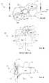
- FIGS. 1 A- 1 Care various views of an implant with a locking element disposed therein according to one embodiment of the disclosure.
- FIG. 1 Dis a sectional view of the implant and locking element of FIG. 1 A .
- FIG. 1 Eis a sectional view of the implant of FIG. 1 A .
- FIGS. 1 F- 1 Gare views of the locking element of FIG. 1 A .
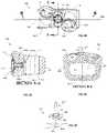
- FIGS. 2 A- 2 Care various views of an implant with a locking element disposed therein according to another embodiment of the disclosure.
- FIG. 2 Dis a sectional view of the implant and locking element of FIG. 2 B .
- FIGS. 2 E- 2 Fare views of the locking element of FIG. 2 B .
- FIGS. 3 A- 3 Care various views of an implant with a locking element disposed therein according to another embodiment of the disclosure.
- FIGS. 3 D- 3 Eare sectional views of the implant and locking element of FIG. 3 A .
- FIGS. 3 F- 3 Gare views of the locking element of FIG. 3 A .
- FIGS. 4 A- 4 Care various views of an implant with a locking element disposed therein according to another embodiment of the disclosure.
- FIGS. 4 D- 4 Eare sectional views of the implant and locking element of FIG. 4 A .
- FIGS. 5 A- 5 Care various views of an implant with a locking element disposed therein according to another embodiment of the disclosure.
- FIG. 5 Dis a perspective view of the implant and locking element of FIG. 5 A during assembly.
- FIG. 5 Eis a sectional view of the implant and locking element of FIG. 5 A .
- FIGS. 6 A- 6 Care various views of an implant with a locking element disposed therein according to another embodiment of the disclosure.
- FIG. 6 Dis a perspective view of the implant and locking element of FIG. 6 A during assembly.
- FIG. 6 Eis a sectional view of the implant and locking element of FIG. 6 A .
- FIGS. 7 A- 7 Care various views of an implant with a locking element disposed therein according to another embodiment of the disclosure.
- FIG. 7 Dis a perspective view of the implant and locking element of FIG. 7 A during assembly.
- FIG. 7 Eis a sectional view of the implant and locking element of FIG. 7 A .
- FIGS. 8 A- 8 Care various views of an implant with a locking element disposed therein according to another embodiment of the disclosure.
- FIG. 8 Dis a perspective view of the implant and locking element of FIG. 8 A during assembly.
- FIGS. 9 A- 9 Care various views of an implant with a locking element disposed therein according to another embodiment of the disclosure.
- FIG. 9 Dis a perspective view of the locking element of FIG. 9 A .
- FIG. 10is a side view of a locking element according to another embodiment of the disclosure.
- FIGS. 11 , 12 A- 12 Bare various views of a locking element according to another embodiment of the disclosure.
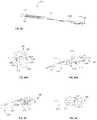
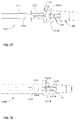
- FIGS. 13 , 14 A, 14 Bare views of an implant inserter system and implant according to another embodiment of the disclosure.
- FIGS. 15 and 16are views of an implant inserter system and implant according to another embodiment of the disclosure.
- FIGS. 17 - 18are steps in a method of engaging an implant with the inserter of FIG. 13 according to another embodiment of the disclosure.
- FIGS. 19 - 20are steps in a method of engaging an implant with an inserter according to another embodiment of the disclosure.
- FIGS. 21 - 24are steps in a method of implanting an intervertebral implant into an intervertebral space according to another embodiment of the disclosure.
- FIGS. 25 A-Bare perspective and close up sectional views of a first step in a method of assembly of an intervertebral implant according to one embodiment of the disclosure.
- FIGS. 26 A-Bare perspective and close up sectional views of a second step in the method of assembly of the intervertebral implant of FIGS. 25 A-B .
- the term “superior”refers to a portion of the implant nearer the patient's head, while the term “inferior” refers to a portion of the implant nearer the user's feet, when the implant is implanted in an intended position and orientation.
- the term “anterior”refers to a portion of the implant nearer the front of the patient
- the term “posterior”refers to a portion of the implant nearer the rear of the patient
- the term “medial”refers to a portion of the implant nearer the mid-line of the patient
- the term “lateral”refers to a portion of the implant farther away from the mid-line of the patient.
- leadingrefers to a portion of the implant that is inserted into the patient ahead of the remainder of the implant while conversely, the term “trailing” refers to a portion of the implant closest to an inserter instrument and is the last part of the implant inserted into the patient.
- the present disclosurerelates to an implant including a locking element adapted for use in an intervertebral region within a spine.
- locking elementis used interchangeably with the term “fastener blocker.”
- the implantis a standalone implant.
- the implantis a monolithic structure and as such does not require assembly of separate parts to form an entirety of the structure.
- the implant bodymay be monolithic with a separate locking element irremovably disposed therein.
- an additive manufacturing processis used because the combined implant and locking element cannot be manufactured using a subtractive manufacturing process.
- additive manufacturemay be layer-by-layer using an additive layer manufacturing (“ALM”), i.e., 3D printing, process.
- ALMadditive layer manufacturing
- SLSselective laser sintering
- SLMselective laser melting
- EBMelectron beam melting
- implant 100is an intervertebral cage as shown in FIGS. 1 A- 1 C and includes a complementary locking element 150 .
- the implantis generally shaped in the form a rectangular prism, though does include prominent protruding features adjacent to trailing surface 102 .
- the implantincludes a superior surface 110 , an inferior surface 112 , side surfaces 106 , 108 , a trailing surface 102 and a leading surface 104 .
- Superior and inferior surfaces 110 , 112are generally parallel to one another though taper slightly from the trailing surface toward the leading surface while trailing surface 102 and leading surface 104 are generally parallel to one another, as shown in FIG. 1 C .
- Side surfaces 106 , 108taper toward one another from the leading surface toward the trailing surface, as shown in FIG. 1 B .
- the above described regions of the implantdefine a generally uniform profile, although adjacent to trailing surface 102 , the above described external surfaces include protrusions, as shown in FIGS. 1 A and 1 C .
- superior surface 110includes a protrusion in the form of ridge 134 while inferior surface 112 includes a protrusion in the form of ridge 132 .
- superior surface 110 and inferior surface 112includes a plurality of fins 114 A, 114 B, respectively, shown in FIG. 1 C . Each fin is oriented so that a length of the fin extends from one side surface to the other.
- implant 100includes lamellar features in the form of channels through a body of the implant, as best shown in FIGS. 1 A- 1 C .
- the channels as shownare diamond shaped and provide the implant with a customized density and/or variation in density over the implant volume that may mirror that found in certain bone structures, e.g., lamellar patterns.
- the channelsmay be circular, another shape, or have more than one shape among the channels of the implant. Further examples and embodiments of implants with various channel configurations are described in U.S. Pat. Nos. 9,987,051, 10,028,841 and D824,518, the disclosures of which are hereby incorporated by reference herein in their entirety.
- implant 100includes three sets of channels, each oriented orthogonally relative to the other two.
- a first grouping of channelsare side channels 119 that extend approximately parallel with trailing and leading surfaces 102 , 104 .
- side channels 119are closely spaced and may be equidistant from one another measured in section approximately parallel to the side surfaces.
- Each channelis linear and includes a gap through central opening 113 , as shown in FIG. 1 B .
- one or more channelsmay extend fully between the side surfaces of the implant.
- a second group of channelsare vertical channels 118 , best shown in FIGS. 1 A and 1 B .
- Each vertical channel 118is oriented in the superior-inferior axis when the implant is disposed in a spine. Channels may be approximately equally spaced from one another and are distributed around a body of the implant on all sides of opening 113 , as shown in FIG. 1 B . Some of the individual channels of the vertical channels 118 extend from a surface defining one of openings 122 , 124 , described in greater detail below, to one of superior surface 110 and inferior surface 112 , as shown in FIG. 1 A . Finally, a third group of channels 117 extend in a leading-trailing axis from leading surface 104 to central opening 113 , as shown in FIG. 1 B .
- Channels 117may also be equally spaced from one another although as a group, as with the other channels, any pattern for the channels is contemplated. Additionally, channels may have varied spacing to fit around openings and other structural features of the implant body. The channels in the implant promote improved bone ingrowth and bone ongrowth. Further, inclusion of channels through the implant provides improved visualization through the implant both in person and via X-ray. For example, visualization is improved compared to solid titanium.
- the implantalso includes a central opening 113 that extends through the implant from the superior surface to the inferior surface, as shown in FIG. 1 B .
- Central opening 113is irregularly shaped, though an exact shape of the central opening may be different in alternative arrangements to accommodate particular surgical applications.
- the implantalso includes a series of surfaces recessed from trailing surface 102 and leading to central longitudinal opening 111 .
- central longitudinal opening 111is a passage extending an entirety of a distance between trailing surface 102 and central opening 113 .
- Central longitudinal opening 111is centered coincident with a central longitudinal axis 182 of implant 100 and is sized for disposal of locking element 150 therein. As shown in FIG. 1 B , central longitudinal axis 182 is midway between side surfaces 106 , 108 .
- FIG. 1 Eillustrates the trailing surface of the implant without the locking element.
- recessed surface 191Located internal to trailing surface 102 is recessed surface 191 , the recessed surface having an arcuate perimeter in superior and inferior directions and following a path of openings 122 , 124 on sides separating the superior and inferior sides.
- the perimeter of recessed surface 191is shaped to follow a footprint of the locking element through its range of rotational movement on the surface. This principle similarly applies to many of the other implants described herein.
- a depth of recessed surface 191is sufficient so that head 152 of locking element 150 may be disposed therein.
- opening 111Within recessed surface 191 is opening 111 , with additional recessed areas extending outward from opening 111 immediately below recessed surface 191 .
- indentations 192 , 193spaced apart from one another.
- groove 196with a surface that extends circumferentially around part of opening 111 from a first end 196 A to a second end 196 B.
- the above described surface featuresare sized and positioned to receive complementary features on locking element 150 .
- protrusion 163 of locking elementis disposable in either indentation 192 , 193 and movable between the two by rotation of locking element 150 when the locking element is in the implant.
- Upper protrusion 168slides within groove 196 between its ends 196 A-B. Details of locking element 150 are described below.
- trailing surface 102 of the implantalso includes two additional openings 122 , 124 , each located peripherally relative to central longitudinal opening 111 , as shown in FIGS. 1 A and 1 E . These openings are also interchangeably referred to as passageways throughout the disclosure.
- Each opening 122 , 124extends into a body of the implant at an angle relative to a transverse plane 184 through the implant, as shown in FIGS. 1 A and 1 C .
- Transverse plane 184is a central plane through the implant that is located in between the superior and the inferior surface.
- a vector representing a central path of opening 122 from the trailing surface into the body of the implantis in an inferior direction away from transverse plane 184
- a vector representing a central path of opening 124 from the trailing surface of the body into the body of the implantis in a superior direction away from transverse plane 184
- openings 122 , 124are angled in opposite directions relative to transverse plane 184 .
- Each opening 122 , 124may be angled from approximately 25 to 45 degrees relative to transverse plane 184 when the locking element is disposed in the implant.
- an angle between a central axis through opening 122 and a central axis through opening 124may be in a range from 50 degrees to 90 degrees.
- each opening 122 , 124is equal and opposite.
- each opening 122 , 124may be angled at 35 degrees relative to transverse plane 184 for a total angle of 70 degrees between central axes of openings 122 , 124 .
- one openingis at a 35 degree angle relative to transverse plane 184 .
- each opening sized for fastener placementis parallel to the other when viewed in the transverse plane. Put another way, the openings remain at the same lateral distance from central longitudinal axis 182 over their length.
- the location of openings 122 , 124 on the implant and their associated angulationis advantageous in that it allows for fasteners disposed in the openings to engage a vertebra near one of its corners when the implant is disposed in an intervertebral space.
- Trailing surface 102also includes notches 138 A-B on opposite sides of trailing surface 102 at side surfaces 106 , 108 , respectively. Each notch 138 A-B is approximately aligned with transverse plane 184 . Notches 138 A-B are sized for engagement by a tool, such as an insertion instrument, described in greater detail elsewhere in the present disclosure.
- implant 100includes ridges 132 , 134 that protrude relative to other more planar surfaces of the implant.
- ridge 132extends outward from inferior surface 112 while ridge 134 extends outward from superior surface 110 .
- Each ridge 132 , 134defines part of the respective opening 122 , 124 entry on trailing surface 102 .
- each ridge 132 , 134is arcuate in shape with a concave surface facing inward toward a respective opening.
- each ridge 132 , 134is angled to align with a pathway of a respective opening.
- the inside surface of ridges 132 , 134may define a partially cylindrical shape with a center becoming further from transverse plane 184 at locations of the implant further from trailing surface 102 .
- a superior apex of the inner surface of ridge 132may be at a 35 degree angle relative to the transverse plane.
- Each ridge 132 , 134is shallow in depth and recedes to the primary superior and inferior surfaces 110 , 112 , close to trailing surface 102 , as shown in FIG. 1 C .
- ridges 132 , 134on the implant provides geometry to allow for screw trajectories to place screws into corners of the adjacent vertebral bodies. By anchoring screws into corners of the adjacent vertebral bodies, bone purchase and stability is optimized. Additionally, ridges 132 , 134 may provide a stop surface to abut against vertebral bodies when the implant is positioned in an intervertebral space. Also on trailing surface 102 , immediately superior and inferior to central longitudinal opening 111 are respective secondary protrusions 132 A, 134 A that define convex external surfaces. As shown in FIG. 1 A , the curvature of these protrusions is approximately parallel to that of a head of locking element 150 .
- locking element 150includes a head 152 and a shaft 166 extending from one side of the head to a free end 169 .
- a cavity 153that extends through head 152 and into shaft 166 .
- the cavityis oriented and sized to accommodate receipt of a portion of a tool, such as insertion instrument 1300 , described in greater detail elsewhere in the present disclosure.
- a drive element 155shaped to receive a driver (not shown) for actuation of the locking element.
- the drivermay be a screw driver or other similar tool.
- Shaft 166includes an open volume 165 that is carved out of part of a cylindrical surface of shaft 166 .
- Open volume 165is partially enclosed by a flexible bar 161 .
- Flexible bar 161extends from a first end at a base of open volume 165 and opposite a main portion of shaft 166 , to a second, free end closer to head 152 , as shown in FIG. 1 F .
- a protrusion 163extending outward from flexible bar 161 . The inclusion of flexible bar 161 with protrusion 163 allows for locking element 150 to be rotated between at least two locked positions in the implant.
- flexible bar 161 of locking element 150is adapted to flex inward toward shaft 166 to bring protrusion 163 out of a first engagement feature, e.g., indentation 192 , within central longitudinal opening 111 of the implant, and locking element 150 is further adapted to be rotatable so that protrusion 163 may be rotated into a second engagement feature, e.g., indentation 193 , within central longitudinal opening 111 .
- head 152 of locking element 150may partially block openings 122 , 124 .
- openings 122 , 124may be unimpeded.
- rotational adjustment of the locking elementis accompanied by visual, audible and tactile feedback to signal a change in a position of the locking element on or in the implant.
- Locking element 150also includes upper protrusion 168 , shown in FIG. 1 F , directly abutting head 152 and extending outward from shaft 166 .
- Upper protrusion 168is adapted to be disposed in groove 196 , an arcuate-shaped recess in implant 100 , when locking element 150 is disposed in the implant.
- groove 196within recessed surface 191 , has an elongate dimension that limits a range of rotation of upper protrusion 168 by blocking its rotation beyond ends 196 A, 196 B of the arcuate shaped groove. In this manner, an overall rotation of locking element 150 is limited to a predetermined range.
- an implant 200 and complementary locking element 250are as shown in FIGS. 2 A- 2 F .
- implant 200unless otherwise noted, like reference numerals refer to like elements of implant 100 , but within the 200 series of numbers.
- Implant 200has generally the same outer shape as implant 100 , though central opening 213 is a different shape.
- locking element 250 for implant 200is disposed within an internal cavity 211 so that locking element 250 is not removable from the implant 200 after the implant is formed, a process described elsewhere in the present disclosure, e.g., ALM implant formation.
- the location of locking element 250 within implant 200is best shown in FIG. 2 B .
- Trailing access 225is an opening into cavity 211 that is aligned with a longitudinal axis 282 , although access 225 is smaller than head 252 of locking element 250 , thereby preventing locking element 250 from dislodging from implant 200 on the trailing side of the implant.
- cavity 211Within cavity 211 is an outer part and an inner part.
- the outer partis defined by a volume between a trailing wall 203 on the trailing side of the implant and internal surface 291 , as shown in FIGS. 2 B and 2 D .
- the volume of the outer part of cavityis sized for the rotatable disposal of head 252 of implant 200 therein.
- Superior and inferior sides of surface 291are generally arcuate, though each opposing side includes a protrusion 288 , 289 , respectively, sized and positioned to prevent over-rotation of locking element 250 .
- Between the opposing superior and inferior sides of surface 291are openings in the form of side accesses 226 , 227 , or slots, that place cavity 211 in direct communication with openings 222 , 224 .
- locking element 250may be rotatable so that part of the locking element structure enters the passageways through openings 222 , 224 .
- the inner part of cavity 211is recessed and internal to internal surface 291 .
- internal to surface 291are four indentations of which two, 292 A and 292 B, are shown in FIG. 2 D .
- the indentationsare positioned at approximately equal angles with respect to one another as measured from axis 282 , and are each sized for the disposal of one of protrusions 263 A, 263 B therein. In this manner, in any fixed rotational position of locking element 250 within implant 200 , protrusions 263 A, 263 B occupy two of the four indentations.
- the locking elementincludes a head 252 and a shaft 266 extending from the head. Extending outward from the shaft on opposite sides are flexible bars 261 A, 261 B, separated from a main body of shaft 266 by open volumes 265 A, 265 B, respectively.
- Each flexible bar 261 A, 261 Bis a cantilever and includes an exterior facing protrusion 263 A, 263 B at its respective free end. Protrusions 263 A, 263 B are sized for disposal in indentations 292 A, 292 B, and the other indentations internal to internal surface 291 .
- Head 252includes a first end portion 256 extending from a center of the locking element, i.e., at a center of drive element 255 , and a second end portion 258 also extending from drive element 255 , but in an opposite direction.
- Each end portionis offset from a superior-inferior axis centerline of locking element 250 , though portion 256 is offset in a first direction while portion 258 is offset in a second, opposite direction. This is best shown in FIGS. 2 D and 2 F .
- One advantage derived from the housing of locking element 250 internally within cavity 211is that locking element 250 is prevented from dislodging from the implant through the trailing face of the implant.
- implant 300 and complementary locking element 350are as shown in FIGS. 3 A- 3 G .
- like reference numeralsrefer to like elements of implant 200 , but within the 300 series of numbers.
- like reference numeralsrefer to like elements of implant 100 , but within the 300 series of numbers.
- implantincludes an inner cavity 311 with an outer part defined between a trailing wall 303 and surface 391 within implant 300 , as shown in FIGS. 3 C and 3 E , and an inner part recessed relative to surface 391 .
- the outer partis bounded by four separate and generally arcuate shaped walls, as shown in FIG. 3 E , each wall separated from the other by accesses 326 , 327 , 328 , 329 .
- Side accesses 326 , 327provide for direct communication between inner cavity 311 and openings 322 , 324 while superior and inferior accesses 328 , 329 provide for direct communication with a superior side and an inferior side of the implant, respectively.
- Two of the walls defining outer part of inner cavity 311oppose one another and include protrusions 388 , 389 , respectively, sized and positioned to limit rotational movement of locking element 350 .
- Interior to internal surface 391are indentations 392 A-D, best shown in FIG. 3 D . Each indentation extends internal relative to surface 391 as part of inner cavity 311 .
- Locking element 350shown in isolation in FIGS. 3 F and 3 G , is sized for disposal within implant 300 and is formed together with implant, e.g., via ALM, so that it is not detachable once the combined structure is formed.
- Locking element 350includes head 352 and two flexible bars 361 A, 361 B extending therefrom. Each flexible bar is a mirror opposite of the other, as shown in FIGS. 3 D and 3 G .
- flexible bar 361 Ahas an arcuate shape that is relatively uniform along its length as measured in a longitudinal axis of the locking element.
- a concave curved recessOn an internally facing surface of flexible bar 361 A is a concave curved recess, thereby providing a pathway through the implant from trailing surface 302 to central opening 313 even with locking element 350 disposed in the implant.
- a protrusion 363 AOn a central externally facing surface of flexible bar 361 A is a protrusion 363 A. Head 352 is sized for disposal in outer part of internal cavity 311 while protrusions 363 A. 363 B are each sized to snap-fit into any one of indentations 392 A-B, 393 A-B, a position of the locking element being adjustable through rotation of locking element within the internal cavity.
- One locked position of locking element 350 within implant 300is illustrated in FIG. 3 D .
- implant 400 and complementary locking element 450are as shown in FIGS. 4 A- 4 E .
- like reference numeralsrefer to like elements of implant 200 , but within the 400 series of numbers.
- like reference numeralsrefer to like elements of implant 100 , but within the 400 series of numbers.
- locking element 450is entirely disposed within implant 400 in a manner such that locking element 450 is held within an internal cavity 411 .
- internal to internal surface 491is an inner part of internal cavity 411 , shown in section in FIG. 4 D .
- the inner partis defined by a perimeter punctuated by protrusions 497 B, 497 D.
- Outer and inner parts of internal cavity 411are sized for the disposal of head 452 and shaft 466 of locking element 450 , respectively.
- Locking element 450includes head 452 and shaft 466 extending therefrom, as shown in FIG. 4 B .
- Shaft 466is a solid body with a partially cylindrical shape extending along a length from the head.
- the shaftincludes troughs 464 A-D, each oriented in a lengthwise manner and spaced apart from the others.
- the geometry of the internal cavity 411 and locking element 450are complementary such that locking element 450 is rotatable within the cavity into more than one locked setting whereby a trough, e.g., 464 A, may be moved from being unengaged with a protrusion to being engaged with protrusion 497 D.
- Such adjustmentschange an orientation of head 452 between a first orientation shown in FIG. 4 E , where head 452 is blocking openings 422 , 424 , and a second orientation where head 452 is entirely over interior surface 491 and no longer blocks either opening 422 , 424 .
- implant 500 and complementary locking element 550are as shown in FIGS. 5 A- 5 E .
- like reference numeralsrefer to like elements of implant 100 , but within the 500 series of numbers.
- like reference numeralsrefer to like elements of implant 100 , but within the 500 series of numbers.
- ridges 532 , 534are reversed relative to the ridges of implant 100 so that ridge 532 protrudes on superior surface 510 while ridge 534 protrudes on inferior surface 512 .
- This configurationis commensurate with opening 522 being angled in a superior direction from the trailing end toward the leading end of the implant while opening 524 is angled in an inferior direction from the trailing end toward the leading end.
- Implant 500includes an internal cavity 511 with an outer part sized to house locking element 550 and an inner part sized to receive pin 570 , as shown in FIGS. 5 B and 5 D . From trailing surface 502 , trailing access 525 through trailing wall 503 connects the trailing surface of the implant to internal cavity 511 .
- the outer part of internal cavity 511extends between wall 503 and internal surface 591 , and is bounded between openings 522 , 524 by four side walls each separated by two of accesses 526 , 527 , 528 , 529 , as shown in FIG. 5 E .
- Side accesses 526 , 527provide space to allow ends of locking element 550 to rotate into openings 522 , 524 , while superior and inferior accesses 528 , 529 connect exterior surfaces of the implant with the internal cavity.
- protrusions 588 , 589provide a blocking surface that limits the extent to which locking element 550 is rotatable within the implant.
- Interior to internal surface 591is inner part of internal cavity 511 including a second recessed volume 515 A and a third recessed volume 515 B, shown in FIGS. 5 B and 5 D .
- recessed volume 515 Bmay directly communicate with internal cavity 511 without a second recessed volume.
- pin 570may be entirely enclosed within recessed volume 515 B below internal cavity 511 .
- the internal cavityas a whole, is sized to accommodate disposal of locking element 550 and pin 570 therein, where pin is disposed through locking element 550 and into third recessed volume 515 B.
- the pin and internal cavityare both shaped and surfaced so that pin 570 engages walls within third recessed volume 515 B through an interference fit.
- Locking element 550is best shown in FIGS. 5 D and 5 E and includes end portions 556 , 558 , a central drive element 555 , and a central opening 553 through the drive element. Locking element 550 does not include a shaft. Rather, opening 553 is sized for the disposal of a pin 570 therein, as shown in FIG. 5 B . Additionally, side accesses 526 , 527 , or slots, in implant 500 are sized and positioned within respective openings 522 , 524 such that locking element 550 is insertable into cavity 511 by sliding it into one of side accesses 526 , 527 , as shown in FIG. 5 D .
- locking element 550complemented by pin 570 , is advantageous in that it can be inserted into a formed implant even when the implant otherwise prevents disengagement of a locking element through trailing surface 502 . It should be appreciated that the assembly of locking element 550 with implant 500 takes place during manufacture.
- implant 600 and complementary locking element 650are as shown in FIGS. 6 A- 6 E .
- like reference numeralsrefer to like elements of implant 200 , but within the 600 series of numbers.
- like reference numeralsrefer to like elements of implant 100 , but within the 600 series of numbers.
- ridges 632 , 634are reversed relative to the ridges of implant 100 , but that the ridge structures are otherwise the same as those described for implant 100 or contemplated alternatives.
- implant 600includes an interior cavity 611 in communication with trailing surface 602 via trailing access 625 .
- interior cavity 611Within interior cavity 611 is an outer part between wall 603 and internal surface 691 and an inner part within recessed volume 615 .
- a volume of upper partis defined by parallel walls that are diagonal to side surfaces 606 , 608 of implant 600 , as shown in FIG. 6 E , and includes blocking protrusions 688 , 689 to prevent over-rotation of locking element 650 .
- Outer part of interior cavity 611is in communication with four access regions, i.e. slots, including side accesses 626 , 627 , superior access 628 and inferior access 629 .
- Each access 626 , 627 , 628 , 629is fully enclosed on all sides and has dimensions sufficient so that locking element 650 may be slid from outside of the implant into cavity 611 via either opening 622 , 624 or via superior or inferior surfaces 610 , 612 .
- locking element 650is shown as ready for insertion through inferior access 629 .
- the implantmay include any sub combination of the four described access slots. For instance, three access openings in total: one on the superior surface and one in each fastener opening.
- the outer part of interior cavity 611is sized to house locking element 650 with a pin 670 disposed therein, the pin further extending into recessed volume 615 .
- Locking elementincludes a drive element 655 and an opening 653 through the drive element, the opening at a center of the locking element and sized for receipt of pin 670 .
- pinincludes a lip, though pin may have alternative surface features chosen to suit the interconnectivity between the pin and the locking element.
- Pin 670 disposed in locking element 650 within implant 600is shown in FIG. 6 E . Locking element 650 is held in position within implant 600 by pin 670 , which maintains an orientation of the locking element relative to the implant.
- Pin 670is held fixed via an interference fit, i.e., press or friction fit, between pin 670 and walls of recessed volume 615 , although it is contemplated that other forms of interconnection between the pin and the implant may also be employed.
- locking element 650is formed within or placed in implant 600 during manufacture.
- implant 700 and complementary locking element 750are as shown in FIGS. 7 A- 7 E .
- like reference numeralsrefer to like elements of implant 300 , but within the 700 series of numbers.
- like reference numeralsrefer to like elements of implant 100 , but within the 700 series of numbers.
- ridges 732 , 734are reversed relative to the ridges of implant 100 , but that the ridge structures are otherwise the same as those described for implant 100 or contemplated alternatives.
- implant 700includes an interior cavity 711 in communication with trailing surface 702 via trailing access 725 .
- an outer partbetween trailing wall 703 and internal surface 791 and an inner part corresponding to recessed volume 715 .
- a volume of upper partis defined by three walls, one on a superior side of the upper part, another on a side facing opening 722 , and a third on a side facing opening 724 .
- the second and third wallsare separated by inferior access 729 , while the first wall of the outer part is separated from the other walls by side accesses 726 , 727 .
- Each access 726 , 727 , 729is a fully enclosed on all sides.
- the first wall and the third wallinclude blocking protrusions 788 , 789 , respectively, to prevent over-rotation of locking element 750 , when disposed in the implant.
- outer part of interior cavity 711is in communication with three access regions, including side accesses 726 , 727 and inferior access 729 .
- Access 729has dimensions sufficient so that locking element 750 may be slid from outside of the implant into cavity 711 .
- FIG. 7 Dlocking element 750 is shown as ready for insertion through inferior access 729 .
- implant 700may also include an access opening from the superior surface in addition to or as a substitute for inferior access 729 .
- the outer part of interior cavity 711is sized to house locking element 750 with a pin 770 disposed therein, the pin also extending further into an inner part of interior cavity 711 , the inner part being recessed volume 715 that extends directly into central opening 713 of implant.
- Locking element 750includes an elongate slot 753 through its central axis with a widened opening 754 at its center, as shown in FIG. 7 D .
- Pin 770includes a head with a drive element 772 therein. In this manner, when pin 770 is engaged with locking element 750 , driving of the combined structure may be through the pin.
- Pin 770also includes protrusions along its shaft, particularly immediately underneath the head, to hold pin rotationally fixed relative to locking element 750 . In this manner, rotation of drive element 772 when pin is disposed in locking element causes the combined pin and locking element structure to rotate together.
- pin 770disposed through locking element 750 , is disposed within recessed volume 715 to form an interference fit with the implant body and locking element 750 is in turn held in place by pin. It should be appreciated that in alternative arrangements, other forms of interconnection between the pin and the implant may be employed.
- locking element 750is formed within or placed in implant 700 during manufacture.
- implant 800 and complementary locking element 850are as shown in FIGS. 8 A- 8 D .
- like reference numeralsrefer to like elements of implant 100 , but within the 800 series of numbers.
- Implant 800includes a recessed surface 891 for receipt of a head 852 of locking element 850 , as shown in FIGS. 8 A and 8 B .
- Recessed surface 891is shaped to accommodate rotation of locking element 850 when it is included therein, with protrusions 888 , 889 extending inward closer to central axis 882 to limit the rotation of locking element.
- Interior to recessed surface 891is central longitudinal opening 811 , best shown in FIG. 8 B , sized to accommodate disposal of a shaft of a locking element therein.
- central longitudinal opening 811includes a wider portion to match a shape of shaft 866 of locking element, which is wider at opposite ends, as shown in FIG. 8 B .
- implant 800is similar to that utilized for implant 200 , and is described in greater detail elsewhere in the disclosure.
- Locking element 850includes a head with offset end portions 856 , 858 extending to ends of the locking element and a drive element 855 at its center longitudinal axis, as shown in FIG. 8 A .
- Shaft 866extends from the head and includes indents 864 A-D similar to those described for implant 400 .
- the indents on shaft 866are sized and positioned so that locking element 850 may be rotatably fixed in different positions by moving an indentation into and out of one of protrusions 897 A, 897 C within central longitudinal opening 811 .
- indentation 864 Amay be moved from being on receiving protrusion 897 A, as shown in FIG. 8 D , to a position between protrusions 897 A, 897 C in a ninety degree rotation of locking element 850 about axis 882 .
- implant 900 and complementary locking element 950are as shown in FIGS. 9 A- 9 D .
- like reference numeralsrefer to like elements of implant 100 , but within the 900 series of numbers.
- ridges 932 , 934are reversed relative to the ridges of implant 100 , but the ridge structures are otherwise the same as those described for implant 100 or contemplated alternatives.
- Implant 900includes a recessed surface 991 internal to trailing surface 902 , and recessed relative to recessed surface 991 is internal cavity 911 , shown in FIGS. 9 B and 9 C .
- Internal cavity 911is generally of uniform size, though widens at its terminal end remote from trailing surface 902 .
- Recessed surfaceis sufficiently interior to trailing surface 902 so that locking element 950 head is disposable therein while internal cavity 911 is sized to receive a shaft in the form of flexible bars 961 A, 961 B extending from head 952 of locking element 950 .
- locking element 950is hollow with a central passage of sufficient size to accommodate disposal of pin 970 therein.
- locking element 950includes head 952 and a shaft 966 extending therefrom. Shaft 966 splits into two flexible bars 961 A-B, separated by a slit 965 . At free ends of each flexible bar are protrusions 963 A, 963 B extending outward from the shaft in opposite directions. Locking element 950 includes a drive element 955 and an opening or cannulation is internal to the drive element for disposal of a pin therein.
- pin 970is placed within locking element 950 and protrusions 963 A-B at a free end of the locking element are pushed outward against the walls of internal cavity 911 , thereby holding locking element 950 in place within the implant.
- the inclusion of pin 970 within locking element 950prevents withdrawal of the locking element from the implant.
- Both locking element 950 and pin 970provide an interference fit engagement.
- a locking elementmay engage an implant with a snap fit in a longitudinal direction instead of a radial direction, as with locking element 1050 shown in FIG. 10 .
- Locking element 1050includes head 1052 and shaft 1066 extending therefrom. Within head 1052 is a flexible bar 1061 separated by the remainder of the head by slot 1065 . At a free end of flexible bar 1061 is a protrusion 1063 extending toward a free end of shaft 1066 .
- screws in an intervertebral implantmay be blocked by snapping locking element 1050 into exterior/outward facing notches or recesses in the implant.
- the locking elementis adapted so that when rotated, flexible bar 1061 bends inward and narrows slot 1065 to disengage from a notch, then once rotated to another notch, snaps back into place.
- a locking element for an implantis in the form of a lever mechanism 1150 that is rotatable into a final position to hold a screw in place in the implant and prevent back out.
- lever mechanismis a two-part structure pivotable about a meeting point between the two parts.
- a first part 1152 and a second part 1154 of the lever mechanismare both U-shaped.
- the U-shaped bodies of lever mechanism 1150are sized to be narrower than a head of a screw to be inserted into the implant.
- Second part 1154is orthogonal to first part 1152 .
- At a free end of second part 1154 remote from the first partis an engagement feature 1155 .
- a diameter of second part 1154is less than a diameter of first part 1152 .
- Lever mechanism 1150is fixed to an implant 1100 at a juncture between the two parts, as shown in FIGS. 12 A, 12 B and is positioned so that it is rotatable until second part 1154 engages a wall of opening 1122 and engagement feature 1155 locks into place within a second engagement feature 1123 .
- two or more of the locking element structures and concepts described hereinmay be included on a trailing surface of an intervertebral implant to block, collectively, three or four or more bone fasteners.
- a locking elementmay be used to block a single bone fastener.
- an implant 1700includes a locking element 1750 in the form of a wave spring, as shown in FIGS. 25 A- 26 B .
- a locking element 1750in the form of a wave spring, as shown in FIGS. 25 A- 26 B .
- Implant 1700is sized to receive locking element 1750 and includes a recessed surface 1791 on its trailing surface 1702 , as shown in FIG. 25 B , for example.
- Recessed surface 1791extends between openings 1722 , 1724 , the openings being for receipt of fasteners within the implant.
- grooves 1788 , 1789 shown in FIG. 25 Bare grooves 1788 , 1789 shown in FIG. 25 B .
- Locking element 1750is flexible and sized to snap into grooves 1788 , 1789 , as described in greater detail in the method.
- Locking element 1750includes a widened central region with side portions 1751 , 1752 , and narrowed, loop ends 1756 , 1758 . Collectively, side portions and narrowed loop ends from a continuous, enclosed structure, as shown in FIG. 25 A .
- Locking element 1750has a length such that, when overlaid or within trailing surface 1702 , each loop end 1756 , 1758 covers a respective opening 1722 , 1724 in the implant. Further, when the locking element is not compressed, a dimension between outside edges of side surfaces 1751 , 1752 is greater than a width into recessed surface 1791 .
- On respective side portions 1751 , 1752are inward facing enclosed structures that encircle holes 1753 , 1754 . Holes 1753 , 1754 are sized for engagement with a holding instrument.
- insertion instrument 1300is as shown in FIGS. 13 , 14 A, 14 B and 17 - 18 .
- insertion instrument 1300includes a handle 1302 and an outer shaft 1311 extending from the handle. Additionally, within the handle and outer shaft is an axially translatable inner shaft 1313 shown in FIGS. 17 - 18 .
- engagement features for engagement to an implantsuch as implant 100 shown engaged to the insertion instrument in FIGS. 13 , 14 A, 14 B and 17 - 18 .
- Outer shaft 1311is generally tubular and extends to a distal end.
- first and second longitudinally extending prongs 1314 A, 1314 Bextend to free ends, as shown in FIGS. 17 and 18 .
- each prongbecomes wider in a direction facing the opposite prong.
- reference numerals 1315 A, 1315 Bare denoted by reference numerals 1315 A, 1315 B, respectively.
- tubular outer shaftmay extend to the distal end and include circumferentially spaced slots so that the entire tubular structure of the outer shaft expands upon receipt of the inner shaft as it advances distally.
- reverse-taper of the prongsmay be substituted with protrusions having other shapes that provide an increased thickness at the distal end of the insertion instrument.
- distal regionincludes a widened body with angled fastener openings 1322 , 1324 passing therethrough, as best shown in FIG. 14 A .
- the fastener openingsare positioned and angled to correspond to openings in the implant to be implanted, e.g., openings 122 , 124 for implant 100 .
- This arrangementis advantageous in that bone fasteners may be inserted into an implant while the insertion instrument is engaged to the implant, with space available to do so as shown in FIG. 14 A .
- alignment arms 1342 , 1344Peripherally and extending longitudinally on the outsides of fastener openings are alignment arms 1342 , 1344 , each including an inward facing prong (not shown) at a respective free end. While engaged to an implant, such as implant 100 , the prongs of arms 1342 , 1344 engage within notches 138 A, 138 B of the implant.
- the armsare advantageous in that while engaged to notches in the implant, the rotation of the implant relative to the insertion instrument is minimized.
- Axial translation of inner shaft 1313is controllable through a position of lever arm 1334 relative to handle 1302 .
- rotation of lever arm 1334 about a pivot point at base 1333causes inner shaft 1313 to move axially. Because the pivot point for lever arm is offset relative to a connection point between the lever arm and inner shaft 1313 , rotation of the lever arm causes inner shaft to be pushed or pulled with respect to the base of the lever arm upon its rotation.
- the actuation mechanism and the lever armare connected to one another through an internal link.
- the internal linkis connected to the inner shaft at one end and the lever arm at the other end, with a pin connection at both ends.
- the lever arm 34is connected to the handle via a third pin separate from the first and second pins, and located at a location closer to an internal end of the lever arm than the pin for the internal link. Through the pin connection, the lever arm is pivotable about an axis through the third pin.
- a bottom surface of the handle opposite the lever armincludes a lock button that is secured to the handle via a pin that is threaded into a corresponding thread in a ball detent, disposed internally within the handle.
- the ball detentis disposed within the handle such that it lies immediately proximal to an internally disposed portion of lever arm. Proximal to the ball detent is a spring and then an end cap closing the enclosed channel of the handle at an end of insertion instrument.
- the ball detentis axially adjustable from a biased position abutting the lever arm to a retracted position, with spring compressed, that is spaced apart from the lever arm.
- lock buttonis actuatable to retract the ball detent.
- This specific configurationprovides a mechanism to control whether the lever arm may be rotated. When the lock button is retracted, the lever arm may be rotated. When the lock button is not, then the lever arm is locked in place.
- the operative connection between the lever arm and the inner shaftis such that rotation of lever arm 1334 about the base causes inner shaft 1313 to move axially either distally or proximally.
- buttons 1320Toward a distal end of outer shaft 1311 is a button 1320 secured thereto via internal springs (not shown) internal within the outer shaft. Without load applied to button 1320 , button 1320 is biased in a raised position relative to a surface of outer shaft 1311 , as shown in FIG. 13 , for example. However, button 1320 may be depressed with the application of forces thereon, thereby compressing the internal springs.
- One function of the buttonis to prevent axial movement of drill guide 1350 in a proximal direction when attached to insertion instrument 1300 , as shown in FIG. 14 B .
- outer shaft 1311towards its distal end, also includes a pair of engagement features on opposing lateral sides that are in the form of longitudinally extending slots. These slots are sized for the disposal of engagement features of a drill guide 1350 therein.
- Insertion instrument 1400is shown in FIGS. 19 - 20 .
- Insertion instrument 1400includes a cannulated outer shaft 1409 with distally extending end arms 1442 , 1444 that extend longitudinally from an end region of the outer shaft.
- Each end arm 1442 , 1444is pivotably connected to the outer shaft so that inward facing protrusions 1443 , 1445 at the ends of the respective arms 1442 , 1444 may be actuated through pivoting of arms 1442 , 1444 .
- a sleeve slidable over arms 1442 , 1444may be included to function as an actuation mechanism, the sleeve sliding along a length of the arms to control their orientation relative to a central axis of the instrument.
- armsmaybe flexibly connected to the outer shaft and bend in an outward direction upon application of force from an inside of the arms.
- the armsmay be biased to be parallel with the central axis of the instrument or biased slightly inward.
- Arms 1442 , 1444may extend from outer shaft 1409 at respective hinge points, e.g., 1442 A, 1444 A, respectively.
- the actuation function of arms 1442 , 1444may be derived from a variety of arrangements. For example, from active control, the material properties of the arms themselves or from a living hinge, among others.
- intermediate shaft 1411Internal to outer shaft is cannulated intermediate shaft 1411 , and internal to intermediate shaft 1411 is inner shaft 1413 with a head 1415 extending radially outward relative to a central longitudinal axis of inner shaft 1413 .
- headis closer in size to inner shaft 1413 .
- headmay be threaded.
- any number of inner or outer sleeves and or shaftsmay be included with the instrument.
- protrusions 1443 , 1445 on arms 1442 , 1444are sized for engagement within notches, e.g., 1638 A, 1638 B on implant 1600 , on corner surfaces at the sides of an intervertebral implant while head 1415 of inner shaft 1413 is disposable within a complementary cavity within an appropriately sized implant, e.g., implant 1600 .
- head 1415may have elastically deformable physical properties to provide for bending of head 1415 when pressed against surfaces so that head 1415 may be advanced through passages smaller than dimensions of the head, such as a cannulation through a locking element, e.g., locking element 1650 .
- implant 1600may include threads on an interior surface adjacent to locking element 1650 , the threads being complementary to threads on head 1415 of inner shaft 1413 .
- inner shaft 1413may have both a smaller size than head 1415 and less flexibility while still being translatable through locking element 1650 in implant 1600 .
- Insertion instrument 1500is adapted for use with a variety of implant sizes although does not include openings to provide for fastener insertion while engaged to an implant.
- the insertion instrumentmay be varied in many ways.
- the distal end region of the outer shaft and/or intermediate shaftmay include prongs adapted to engage interior walls of an implant where the implant does not include a locking element disposed therein. This design may be desirable where a locking element to be used is not cannulated.
- the present disclosurerelates to a system including an insertion instrument and an intervertebral implant.
- an insertion instrumentsuch as those described herein may be used in conjunction with any implant having a vacant central opening so that longitudinally extending prongs of the insertion instrument may be inserted therein.
- a systemincludes an insertion instrument, an intervertebral implant and a drill guide structure, such as drill guide 1350 shown in FIG. 14 B .
- Drill guide 1350includes a longitudinally extending engagement feature (not shown) along its length to engage with an insertion instrument and may be held in place axially through a back stop provided by button 1320 , again, as shown in FIG. 14 B .
- Drill guide 1350includes guide holes 1352 , 1354 protruding from a main body and angled in opposite directions, the angulation corresponding to an angulation of openings in the implant attached to the insertion instrument.
- the present inventionrelates to a method of manufacturing an intervertebral implant.
- the implantis formed using an ALM fabrication process such as SLS, SLM or EBM described above, fused deposition modeling (FDM), or another appropriate 3D printing technology known to those skilled in the art.
- ALM fabrication processsuch as SLS, SLM or EBM described above, fused deposition modeling (FDM), or another appropriate 3D printing technology known to those skilled in the art.
- FDMfused deposition modeling
- articlesare produced in layer-wise fashion according to a predetermined digital model of such articles by heating, e.g., using a laser or an electron beam, multiple layers of powder, which may be a metallic powder, that are dispensed one layer at a time.
- the powderis sintered in the case of SLS technology and melted in the case of SLM technology, by the application of laser energy that is directed in raster-scan fashion to portions of the powder layer corresponding to a cross section of the article. After the sintering or melting of the powder on one particular layer, an additional layer of powder is dispensed, and the process repeated, with sintering or melting taking place between the current layer and the previously laid layers until the article is complete.
- the powder layerssimilarly may be heated with EBM technology. Additive manufacturing techniques such as the ALM processes described above may be employed to form the implant, the locking element, or the combination of the implant and the locking element. It should also be appreciated that other devices, instruments, or components therefor that are contemplated by this disclosure may also be formed through an ALM process. In some instances, materials for one layer may be different than the materials for successive layers.
- an implant and accompanying locking elementare formed through a single, continuous ALM process.
- the combined structuresare formed layer by layer through a single step.
- This approachmay be employed to form any one of implants 100 , 200 , 300 , 400 , 800 , 900 , for example.
- the geometry and other properties of the implant and the locking elementare programmed into software associated with the ALM system, e.g., computer and machine, and then used to produce both elements together in a single pass.
- the locking elementis located either on the implant (e.g., implants 100 , 800 , 900 ) or in the implant (e.g., implants 200 , 300 , 400 ).
- an implantis formed through a two-step ALM process where a first part of the implant is formed via ALM, then paused, and then later resumed to completion.
- This ALM processis focused on the implant itself and does not include formation of the locking element, as described in greater detail below.
- the two-step approachis particularly well suited for implants with a locking element enclosed within the implant. More particularly, where the locking element is not formed through ALM, this approach facilitates the inclusion of such locking elements in the implant even when the locking element is disposed in an internal cavity of the implant without openings large enough to insert or remove the locking element.
- the two-step processhas particular applicability as an option for implants 200 , 300 , 400 , 500 , 600 , 700 , 800 for example.
- a first portion of an implantis formed through an ALM technique.
- printingbegins from leading surface 204 and continues toward an opposite end of the implant until just shy of trailing wall 203 . These locations on implant 200 are best shown in FIGS. 2 A and 2 B .
- a moldmay be used to keep the partially formed implant in a fixed location.
- printingis stopped.
- locking element 250is retrieved and disposed in a formed portion of cavity 211 of implant 200 .
- Locking element 250may be formed by any desired method, either subtractive or additive.
- locking element 250may also be formed together with the implant body in a single continuous process. Locking element 250 is checked to confirm it is positioned within cavity 211 at a sufficient depth, then step two of the process may commence. ALM resumes and the remainder of the implant is printed, including trailing wall 203 . In each of the first and second steps, the same pre-programmed model is used to print the implant, so the final implant, even with the break in printing, still reflects the desired properties and dimensions. Indeed, the final implant is a monolithic structure. This method may be similarly performed for implants 300 , 400 , 500 , 600 , 700 .
- a first stepinvolves printing implant 800 from surface 804 to a location on the implant aligned with the narrower portion of the locking element. Then, printing is paused and locking element 850 is inserted from opening 813 into its intended position within the implant. To continue, locking element may need to be temporarily held in place so that it does not become displaced.
- the second stepis then performed by printing the remainder of implant 800 up to surface 802 so that locking element 850 is entirely held within implant 800 , as shown in FIG. 8 B .
- the implantitself may be formed in its entirety through ALM in a continuous single step process without the locking element.
- the locking elementmay be inserted into the implant after formation of the implant via ALM.
- an implantmay simply be inserted into a cavity on a trailing surface of the implant, such as with implants 100 , 900 .
- the cavity for the implantis blocked from the trailing side.
- the implantincludes access passages, i.e., slots, so that the locking element may be slid into the cavity within the implant and secured in place with a pin, for example. Examples of the latter configuration include implants 500 , 600 , 700 .
- implant 500is first formed through a single step continuous ALM process, layer by layer. Then, locking element 550 is slid into cavity 511 through either side access 526 or side access 527 , as shown in FIG. 5 D . Insertion may involve first orienting locking element 550 so its long dimension is perpendicular to a length of the side access opening edge and then advancing it into one of openings 522 , 524 before pushing it into one of the side access openings. Once locking element 550 is centered on central longitudinal axis 582 , pin 570 is used to secure locking element 550 in place. In this method, locking element 550 may be formed through ALM or any other manufacturing process.
- Materials used to form the implant, locking element and/or various components described above with an ALM processinclude, but are not limited to, metals (e.g., metal powder) that may be any one or any combination of titanium and its alloys, stainless steel, magnesium and its alloys, cobalt and its alloys including cobalt chromium alloys, nickel and its alloys, platinum, silver, tantalum niobium, and other super elastic materials such as copper-aluminum alloys.
- metalse.g., metal powder
- titaniume.g., metal powder
- Non-metallic materialsmay also be used and include, but are not limited to, implantable plastics.
- PEEKpolyetheretherketone
- PEKpolyetherketone
- ABSacrylonitrile butadiene styrene
- siliconesilicone
- cross-linked polymersbioabsorbable glass, ceramics, and biological active materials such as collagen/cell matrices.
- PEEKis particularly well suited for the implants described herein.
- Combinations of material typesare also contemplated.
- the implantmay be formed of a titanium coated PEEK. To the extent other materials are described elsewhere in the specification, such materials are also contemplated for use in ALM processes.
- the present disclosurerelates to a method of implanting an intervertebral implant using an implant insertion instrument.
- insertion instrument 1300is used to perform the method. For purposes of illustration, the method will be described with reference to implant 100 , the details of which are shown in FIGS. 1 A- 1 G , for placement into an intervertebral space.
- insertion instrument 1300is engaged with implant 100 , as shown generally in FIG. 21 . Because locking element 150 is built into central longitudinal opening 111 of implant during manufacture, i.e., prior to surgery, as shown in FIG. 1 B, no additional step is required during surgery to engage implant 100 with insertion instrument.
- arms 1342 , 1342are advanced into engagement with notches 138 A, 138 B on sides of trailing surface 102 . Engagement of the arms to the sides of implant stabilizes the implant relative to the insertion instrument and prevents relative rotation.
- a distal end of outer shaft 1311is advanced into a cavity 153 within locking element 150 disposed in implant 100 , a step illustrated in FIG. 17 .
- lever arm 1334is rotated toward the user to push inner shaft 1313 within outer shaft 1311 , advancing inner shaft 1313 as represented in a comparison of FIGS. 17 and 18 .
- the insertion toolis used to advance the implant into a prepared intervertebral space between vertebrae 2 , 4 , as shown in FIG. 22 .
- fastenersare inserted into respective openings 122 , 124 in implant 100 , as shown in FIG. 23 .
- a drill guidesuch as drill guide 1350
- the fastenersmay be advanced into respective vertebrae adjacent to the implant with the insertion instrument engaged to the implant, as shown in FIG. 23 .
- each fastenermay be anchored at a steep angle to provide for anchorage into an outer corner of a respective vertebra when inserted therein.
- instrument 1300is removed and locking element 150 is rotated into a blocking position, as shown in FIG. 24 , to prevent back out of fasteners (fasteners not shown in FIG. 24 ).
- a driveris used to engage drive element 155 , and locking element 150 is rotated ninety degrees to shift the end portions of locking element 150 from a superior-inferior orientation outside of the path of openings 122 , 124 to a sideways oriented direction whereby each end portion blocks a respective opening 122 , 124 .
- the locking elementprovides a visual of the partial coverage of the fastener heads in openings 122 , 124 .
- the locking elementprovides a tactile and audio feedback as it is rotated into a new locked position. For example, as the locking element is rotated into the blocking position, it makes a snap sound as it locks into place, and the user can also feel, through the driver engaged to the locking element, that the locking element is moved into a new locked position.
- Some or all of these visual, audio and tactile feedback mechanismsare similarly present in other implants described in the present disclosure. This completes the implantation of implant 100 . The method may be similarly performed with implant 300 .
- a locking elementis inserted into the implant and secured with a pin during manufacture prior to use of the implant in surgery.
- the locking elementmay be slid into the implant from a side access, e.g., 526 , 527 shown in FIG. 5 D , that is accessible from a fastener opening in the implant.
- the locking elementmay be inserted through an inferior access in the implant, e.g., 629 , 729 , shown in FIGS. 6 D and 7 D .
- a pinmay be inserted through the central opening in the locking element to secure the locking element in place.
- locking element 950 and pin 970may be snapped into place during manufacture of the implant.
- the implantmay be formed with the locking element together in an additive manufacturing process so there is no separate locking element insertion step.
- locking element 1750is inserted into implant 1700 .
- locking element 1750is advanced toward trailing end 1702 of implant, as shown in FIGS. 25 A-B .
- An instrumentmay be used to direct the locking element to the implant through insertion of arms on the instrument through openings 1753 , 1754 .
- the locking elementmay be engaged with another instrument or may be held by hand and placed into the implant.
- chamfers 1761 , 1762 on locking element 1750contact implant chamfers 1793 , 1794 .
- side portions 1751 , 1752flex inward to slide over the lip around the recessed surface of the implant, and then locking element 1750 snaps into place within recessed surface 1791 .
- side portions 1751 , 1752snap into grooves 1788 , 1789 , as shown in FIGS. 26 A-B .
- side portions 1751 , 1752are in tension, thereby holding locking element 1750 in place within implant 1700 .
- loop portions 1756 , 1758are positioned to block openings 1722 , 1724 .
- screwsmay be inserted through openings 1722 , 1724 prior to engagement of locking element 1750 to implant 1700 .
- the locking elementmay be modified to include a central longitudinal cavity for gripping by insertion instrument 1300 to insert the instrument into the implant.
- the pinmay be enlarged and include a cavity therein for insertion of prongs 1314 A, 1314 B.
- another instrumentmay be used to hold the implant and place it into the intervertebral disc space.
- an alternative instrumentmay be forceps or another insertion device with gripping arms structured for engagement with the fastener openings in the implant.
- the forcepsmay grip fastener openings 222 , 224 to hold the implant.
- a fully assembled implanthere, implant 200 with locking element 250 disposed therein, may be delivered to a target site in a patient even without a custom opening in the locking element for engagement by insertion instrument 1300 .
- the forcepsmay be removed and the fasteners implanted through the fastener openings. It should be appreciated that this method may also be used even when use of instrument 1300 is another available option, such as with implant 100 .
- an implantmay be implanted using insertion instrument 1400 in the same manner as that described for insertion instrument 1300 .
- widened head 1415 on inner shaft 1413is advanced through a central opening in a locking element, e.g. locking element 1650 within implant 1600 , and into a widened opening internal to the locking element, as shown FIG. 20 .
- a threaded connectionis formed between head 1415 and implant 1600 .
- inner shaft 1413is held in place with respect to the implant.
- inner shaftmay bend in an elastic manner.
- the headmay be sized to fit through an opening in locking element 1650 .
- arms 1442 , 1444may be actuated to lock into notches 1638 A-B through advancement of a sleeve along the arms.
- an implantmay be implanted using insertion instrument 1500 . Once implant is in position within an intervertebral space, instrument 1500 may be removed prior to advancing bone fasteners through the implant and into vertebral bone structures.
- the step of blocking fasteners inserted into an implantmay be performed with locking mechanism 1150 instead of a locking element such as locking element 150 , as shown in FIGS. 12 A-B .
- a fastenerWith implant in place within an intervertebral disc space, a fastener is directed to an opening 1122 in implant 1100 .
- the head of the fastener having a diameter larger than that of second part 1154causes the second part to be pushed and rotated downward with advancement of the fastener until second part 1154 contacts a wall of opening 1122 , as shown in FIG. 12 B .
- Engagement feature 1155engages with second engagement feature 1123 to secure locking mechanism 1150 in position, and the fastener is prevented from back out by first part 1152 , now parallel to trailing surface 1102 of implant 100 .
- any of the devices and methods disclosed hereincan be used in conjunction with robotic technology.
- any of the implants described hereincan be used with robotic surgical systems to place the implant in a patient.
- the implantcan be manipulated with a robotic system or a robotic arm to rotate or position the implant, and to anchor bone fasteners through the implant during a procedure.
- any or all of the steps described in the methods for performing an implant placement procedure of the present disclosuremay be performed using a robotic system.
- roboticsmay be used in methods of forming the implant with ALM processes.
Landscapes
- Health & Medical Sciences (AREA)
- Engineering & Computer Science (AREA)
- Biomedical Technology (AREA)
- Orthopedic Medicine & Surgery (AREA)
- Transplantation (AREA)
- Life Sciences & Earth Sciences (AREA)
- Neurology (AREA)
- Animal Behavior & Ethology (AREA)
- Veterinary Medicine (AREA)
- Public Health (AREA)
- General Health & Medical Sciences (AREA)
- Heart & Thoracic Surgery (AREA)
- Vascular Medicine (AREA)
- Oral & Maxillofacial Surgery (AREA)
- Cardiology (AREA)
- Physical Education & Sports Medicine (AREA)
- Surgery (AREA)
- Manufacturing & Machinery (AREA)
- Nuclear Medicine, Radiotherapy & Molecular Imaging (AREA)
- Medical Informatics (AREA)
- Molecular Biology (AREA)
- Prostheses (AREA)
Abstract
Description
Claims (20)
Priority Applications (2)
| Application Number | Priority Date | Filing Date | Title |
|---|---|---|---|
| US17/019,912US11534307B2 (en) | 2019-09-16 | 2020-09-14 | 3D printed cervical standalone implant |
| US18/071,137US12409045B2 (en) | 2019-09-16 | 2022-11-29 | 3D printed cervical standalone implant |
Applications Claiming Priority (2)
| Application Number | Priority Date | Filing Date | Title |
|---|---|---|---|
| US201962900937P | 2019-09-16 | 2019-09-16 | |
| US17/019,912US11534307B2 (en) | 2019-09-16 | 2020-09-14 | 3D printed cervical standalone implant |
Related Child Applications (1)
| Application Number | Title | Priority Date | Filing Date |
|---|---|---|---|
| US18/071,137ContinuationUS12409045B2 (en) | 2019-09-16 | 2022-11-29 | 3D printed cervical standalone implant |
Publications (2)
| Publication Number | Publication Date |
|---|---|
| US20210077268A1 US20210077268A1 (en) | 2021-03-18 |
| US11534307B2true US11534307B2 (en) | 2022-12-27 |
Family
ID=72521534
Family Applications (2)
| Application Number | Title | Priority Date | Filing Date |
|---|---|---|---|
| US17/019,912Active2041-01-07US11534307B2 (en) | 2019-09-16 | 2020-09-14 | 3D printed cervical standalone implant |
| US18/071,137Active2041-09-01US12409045B2 (en) | 2019-09-16 | 2022-11-29 | 3D printed cervical standalone implant |
Family Applications After (1)
| Application Number | Title | Priority Date | Filing Date |
|---|---|---|---|
| US18/071,137Active2041-09-01US12409045B2 (en) | 2019-09-16 | 2022-11-29 | 3D printed cervical standalone implant |
Country Status (2)
| Country | Link |
|---|---|
| US (2) | US11534307B2 (en) |
| EP (1) | EP3791832B1 (en) |
Cited By (2)
| Publication number | Priority date | Publication date | Assignee | Title |
|---|---|---|---|---|
| US20230157838A1 (en)* | 2021-02-01 | 2023-05-25 | GS Solutions, Inc. | Implant, system including implant, and method of using system |
| WO2025106249A1 (en)* | 2023-11-14 | 2025-05-22 | Evolution Spine, LLC | Cervical interbody |
Families Citing this family (7)
| Publication number | Priority date | Publication date | Assignee | Title |
|---|---|---|---|---|
| US11224521B2 (en) | 2008-06-06 | 2022-01-18 | Providence Medical Technology, Inc. | Cervical distraction/implant delivery device |
| US11298244B2 (en)* | 2019-01-31 | 2022-04-12 | K2M, Inc. | Interbody implants and instrumentation |
| US11534307B2 (en) | 2019-09-16 | 2022-12-27 | K2M, Inc. | 3D printed cervical standalone implant |
| US11957600B2 (en)* | 2020-02-18 | 2024-04-16 | Mirus Llc | Anterior lumbar interbody fusion device with bidirectional screws |
| WO2022232339A1 (en)* | 2021-04-29 | 2022-11-03 | Providence Medical Technology, Inc. | System and method for lumbar fusion |
| AU2024227340A1 (en) | 2023-10-24 | 2025-05-08 | Howmedica Osteonics Corp. | Modular instrument and methods of using and manufacturing the modular instrument |
| CN119367110B (en)* | 2024-10-29 | 2025-09-02 | 上海三友医疗器械股份有限公司 | Fusion cages and cervical spine surgical components |
Citations (143)
| Publication number | Priority date | Publication date | Assignee | Title |
|---|---|---|---|---|
| US5645084A (en) | 1995-06-07 | 1997-07-08 | Danek Medical, Inc. | Method for spinal fusion without decortication |
| US5669909A (en) | 1995-03-27 | 1997-09-23 | Danek Medical, Inc. | Interbody fusion device and method for restoration of normal spinal anatomy |
| US6086614A (en) | 1998-01-23 | 2000-07-11 | Sulzer Orthopedics Inc. | Orthopedic prosthesis having anti-backout screw |
| US6193721B1 (en) | 1997-02-11 | 2001-02-27 | Gary K. Michelson | Multi-lock anterior cervical plating system |
| US6206922B1 (en) | 1995-03-27 | 2001-03-27 | Sdgi Holdings, Inc. | Methods and instruments for interbody fusion |
| US6235033B1 (en) | 2000-04-19 | 2001-05-22 | Synthes (Usa) | Bone fixation assembly |
| US6245072B1 (en) | 1995-03-27 | 2001-06-12 | Sdgi Holdings, Inc. | Methods and instruments for interbody fusion |
| US6258089B1 (en) | 1998-05-19 | 2001-07-10 | Alphatec Manufacturing, Inc. | Anterior cervical plate and fixation system |
| US6306139B1 (en) | 1998-10-19 | 2001-10-23 | Scint'x | Intervertebral connection device with an anti-extraction device to prevent extraction of anchoring screws |
| US6331179B1 (en) | 2000-01-06 | 2001-12-18 | Spinal Concepts, Inc. | System and method for stabilizing the human spine with a bone plate |
| US6447512B1 (en) | 2000-01-06 | 2002-09-10 | Spinal Concepts, Inc. | Instrument and method for implanting an interbody fusion device |
| US6485517B1 (en) | 1999-05-05 | 2002-11-26 | Gary K. Michelson | Nested interbody spinal fusion implants |
| US6558423B1 (en) | 1999-05-05 | 2003-05-06 | Gary K. Michelson | Interbody spinal fusion implants with multi-lock for locking opposed screws |
| US20030149438A1 (en) | 2001-04-30 | 2003-08-07 | Howmedica Osteonics Corp. | Insertion instrument |
| US6613091B1 (en) | 1995-03-27 | 2003-09-02 | Sdgi Holdings, Inc. | Spinal fusion implants and tools for insertion and revision |
| US20040010259A1 (en) | 2002-03-12 | 2004-01-15 | Waldemar Link Gmbh & Co. | Cervical prosthesis and instrumentation therefor |
| US6695845B2 (en) | 2000-10-16 | 2004-02-24 | Robert A Dixon | Method and apparatus utilizing interference fit screw shanks for nonmetallic spinal stabilization |
| US6730127B2 (en) | 2000-07-10 | 2004-05-04 | Gary K. Michelson | Flanged interbody spinal fusion implants |
| US20040098129A1 (en) | 2002-11-13 | 2004-05-20 | Jo-Wen Lin | Spinal implant insertion adjustment instrument and implants for use therewith |
| US6749636B2 (en) | 2001-04-02 | 2004-06-15 | Gary K. Michelson | Contoured spinal fusion implants made of bone or a bone composite material |
| US6884242B2 (en) | 2001-04-06 | 2005-04-26 | Society De Fabrication De Materiel Orthopedique, S.A. | Anterior plating system and method |
| US6890355B2 (en) | 2001-04-02 | 2005-05-10 | Gary K. Michelson | Artificial contoured spinal fusion implants made of a material other than bone |
| US6902565B2 (en) | 2001-02-21 | 2005-06-07 | Synthes (U.S.A.) | Occipital plate and system for spinal stabilization |
| US6972019B2 (en) | 2001-01-23 | 2005-12-06 | Michelson Gary K | Interbody spinal implant with trailing end adapted to receive bone screws |
| US20050283245A1 (en) | 2003-08-05 | 2005-12-22 | Gordon Charles R | Method of insertion of an expandable intervertebral implant using a tool |
| US6989031B2 (en) | 2001-04-02 | 2006-01-24 | Sdgi Holdings, Inc. | Hemi-interbody spinal implant manufactured from a major long bone ring or a bone composite |
| US7131974B2 (en) | 2003-10-14 | 2006-11-07 | Keyer Thomas R | Surgical drill guide |
| US20070016218A1 (en) | 2005-05-10 | 2007-01-18 | Winslow Charles J | Inter-cervical facet implant with implantation tool |
| US7175624B2 (en) | 2002-12-31 | 2007-02-13 | Depuy Spine, Inc. | Bone plate and screw system allowing bi-directional assembly |
| US7288094B2 (en) | 2005-06-10 | 2007-10-30 | Sdgi Holdings, Inc. | System and method for retaining screws relative to a vertebral plate |
| US7294134B2 (en) | 2004-07-28 | 2007-11-13 | Weber Instrumente Gmbh | Surgical instrument for the introduction of a multi-component intervertebral prosthesis |
| US7306605B2 (en) | 2003-10-02 | 2007-12-11 | Zimmer Spine, Inc. | Anterior cervical plate |
| US7309340B2 (en) | 2003-06-20 | 2007-12-18 | Medicinelodge, Inc. | Method and apparatus for bone plating |
| US7318825B2 (en) | 2003-12-22 | 2008-01-15 | Life Spine Llc | Dynamic cervical plates and cervical plate constructs |
| US20080281425A1 (en) | 2007-02-21 | 2008-11-13 | John Thalgott | Orthopaedic Implants and Prostheses |
| US7527639B2 (en) | 2000-02-01 | 2009-05-05 | Depuy Products, Inc. | Fixation system with multidirectional bone supports |
| US7527629B2 (en) | 2002-03-12 | 2009-05-05 | Cervitech, Inc. | Instrument set for fitting an intervertebral joint prosthesis |
| US7537663B2 (en) | 2002-07-24 | 2009-05-26 | University Of Dayton | Corrosion-inhibiting coating |
| US7537664B2 (en) | 2002-11-08 | 2009-05-26 | Howmedica Osteonics Corp. | Laser-produced porous surface |
| US20090210062A1 (en) | 2008-02-20 | 2009-08-20 | John Thalgott | Orthopaedic Implants and Prostheses |
| US7608080B2 (en) | 2004-07-02 | 2009-10-27 | Warsaw Orthopedic, Inc. | Device for inserting implants |
| US7618418B2 (en) | 2004-04-16 | 2009-11-17 | Kyphon Sarl | Plate system for minimally invasive support of the spine |
| US7635366B2 (en) | 2003-12-29 | 2009-12-22 | Abdou M Samy | Plating system for bone fixation and method of implantation |
| WO2010011849A1 (en) | 2008-07-23 | 2010-01-28 | Malberg Marc I | Modular nucleus pulposus prosthesis |
| US7666185B2 (en) | 2003-09-03 | 2010-02-23 | Synthes Usa, Llc | Translatable carriage fixation system |
| US7674279B2 (en) | 2006-10-13 | 2010-03-09 | Spinal U.S.A. | Bone plate |
| US20100100138A1 (en) | 2005-09-21 | 2010-04-22 | Reynolds Joseph E | Endoscopic Insturments and Mehod for Delivery of Spinal Implant |
| US7736380B2 (en) | 2004-12-21 | 2010-06-15 | Rhausler, Inc. | Cervical plate system |
| US20100256760A1 (en)* | 2009-04-02 | 2010-10-07 | Noah Hansell | Method of Installation of Intervertebral Spacers |
| US7811292B2 (en) | 2004-03-02 | 2010-10-12 | Aesculap Implant Systems, Inc. | Surgical instrument for implants |
| US7875062B2 (en) | 2006-03-07 | 2011-01-25 | Warsaw Orthopedic, Inc. | Methods and devices for retaining bone plate anchors |
| US7901458B2 (en) | 2005-12-16 | 2011-03-08 | Warsaw Orthopedic, Inc. | Intervertebral spacer and insertion tool |
| US7905886B1 (en) | 2003-07-07 | 2011-03-15 | Nuvasive Inc. | System and methods for performing transforaminal lumbar interbody fusion |
| US7914561B2 (en) | 2002-12-31 | 2011-03-29 | Depuy Spine, Inc. | Resilient bone plate and screw system allowing bi-directional assembly |
| US7935137B2 (en) | 2004-12-08 | 2011-05-03 | Depuy Spine, Inc. | Locking bone screw and spinal plate system |
| US7963982B2 (en) | 2007-07-16 | 2011-06-21 | X-Spine Systems, Inc. | Implant plate screw locking system and screw having a locking member |
| US7988714B2 (en) | 2004-10-08 | 2011-08-02 | Aesculap Ag | Bone screw |
| US7998215B2 (en) | 1999-10-21 | 2011-08-16 | Warsaw Orthopedic, Inc. | Devices and techniques for a posterior lateral disc space approach |
| US8043343B2 (en) | 2007-06-28 | 2011-10-25 | Zimmer Spine, Inc. | Stabilization system and method |
| US8062342B2 (en) | 2009-05-15 | 2011-11-22 | Globus Medical, Inc. | Orthopedic plate blocking assembly |
| US8123788B2 (en) | 1997-02-11 | 2012-02-28 | Warsaw Orthopedic, Inc. | Plating system having retaining member that permits movement of at least one bone fastener |
| US8128628B2 (en) | 2002-02-01 | 2012-03-06 | Zimmer Spine, Inc. | Spinal plate system for stabilizing a portion of a spine |
| US8206399B2 (en) | 1998-10-22 | 2012-06-26 | Warsaw Orthopedic, Inc. | Artificial intervertebral joint permitting translational and rotational motion |
| US8216316B2 (en) | 2008-12-17 | 2012-07-10 | X-Spine Systems, Inc. | Prosthetic implant with biplanar angulation and compound angles |
| US8231633B2 (en) | 2005-04-15 | 2012-07-31 | Warsaw Orthopedic | Instruments, implants and methods for positioning implants into a spinal disc space |
| US8287575B2 (en) | 2006-11-09 | 2012-10-16 | Stryker Trauma Gmbh | Polyaxial locking mechanism |
| WO2012141715A1 (en) | 2011-04-15 | 2012-10-18 | Synthes Usa, Llc | Fixation assembly |
| US8298272B2 (en) | 2008-08-12 | 2012-10-30 | Warsaw Orthopedic Inc. | Self-locking surgical fastener |
| US8298235B2 (en) | 2004-09-30 | 2012-10-30 | Depuy Spine, Inc. | Instrument and method for the insertion and alignment of an intervertebral implant |
| US20120277870A1 (en) | 2011-04-29 | 2012-11-01 | Wolters Madeline C | Spinal Interbody Implant With Bone Screw Retention |
| US20120277873A1 (en) | 2007-06-06 | 2012-11-01 | Richard Kana | Interbody fusion device with lipped anterior plate and associated methods |
| US20120277803A1 (en) | 2011-04-26 | 2012-11-01 | Warsaw Orthopedic, Inc. | Bone plate & method for manufacturing |
| US8328872B2 (en) | 2008-09-02 | 2012-12-11 | Globus Medical, Inc. | Intervertebral fusion implant |
| US20130006314A1 (en) | 2011-06-28 | 2013-01-03 | Corelink, Llc | Locking Device for Fixation Mechanism of Medical Implant |
| US8353958B2 (en) | 2006-01-09 | 2013-01-15 | Warsaw Orthopedic, Inc. | Adjustable insertion device for a vertebral implant |
| US8425530B2 (en) | 2004-12-13 | 2013-04-23 | Warsaw Orthopedic, Inc. | Apparatus for sizing a facet joint |
| US8491598B2 (en) | 2008-03-03 | 2013-07-23 | Us Spine, Inc. | Surgical positioning assembly and associated spinal implant device and surgical methods |
| US20130218276A1 (en) | 2012-02-17 | 2013-08-22 | Medacta International Sa | Intervertebral implant with improved fastening system for the fixing plate |
| US8562655B2 (en) | 2008-07-17 | 2013-10-22 | Alphatec Spine, Inc. | Bone plate assembly |
| US20130345813A1 (en) | 2012-06-22 | 2013-12-26 | Sheryl Frank | Dual Anchor Lateral Vertebral Body Fixation Plates |
| US8636804B2 (en) | 2001-07-16 | 2014-01-28 | Spinecore, Inc. | Instrumentation for properly seating an artificial intervertebral disc in an intervertebral space |
| US20140066997A1 (en) | 2012-08-31 | 2014-03-06 | Warsaw Orthopedic, Inc. | Retaining mechanism |
| US8696681B2 (en) | 2005-09-29 | 2014-04-15 | K2M, Inc. | Adjustable interbody introducer device and method |
| US8709083B2 (en) | 2009-06-04 | 2014-04-29 | William E. Duffield | Intervertebral fusion implant |
| US8728387B2 (en) | 2005-12-06 | 2014-05-20 | Howmedica Osteonics Corp. | Laser-produced porous surface |
| US8740983B1 (en) | 2009-11-11 | 2014-06-03 | Nuvasive, Inc. | Spinal fusion implants and related methods |
| US20140200670A1 (en) | 2013-01-16 | 2014-07-17 | Spinefrontier Inc | System and method for a spinal stabilization implant assembly |
| US8795341B2 (en) | 2009-07-24 | 2014-08-05 | Spinal Usa, Inc. | Bone plate screw-blocking systems and methods |
| US8808304B2 (en) | 2010-04-21 | 2014-08-19 | Globus Medical, Inc | Insertion tool assembly |
| US8864829B1 (en) | 2007-07-02 | 2014-10-21 | Theken Spine, Llc | Spinal cage having deployable member |
| US8876835B2 (en) | 2009-12-28 | 2014-11-04 | Safe Orthopaedics | Device for positioning an implant |
| US8882813B2 (en) | 2007-10-19 | 2014-11-11 | Spinesmith Partners, L.P. | Locking mechanisms and associated methods |
| US8882814B2 (en) | 2010-02-02 | 2014-11-11 | Globus Medical, Inc. | Orthopedic plating assembly for bone fixation and subsidence |
| US8906097B2 (en) | 2010-06-02 | 2014-12-09 | Spinecraft, LLC | Intervertebral implant facilitating unilateral placement, instruments and methods |
| US8945227B2 (en) | 2010-02-01 | 2015-02-03 | X-Spine Systems, Inc. | Spinal implant co-insertion system and method |
| EP2865347A1 (en) | 2013-10-09 | 2015-04-29 | Stryker Spine | Pivoting vertebral plate |
| US9028498B2 (en) | 2013-03-14 | 2015-05-12 | Innovasis, Inc. | Modular bone fixation plate assembly |
| US20150216573A1 (en) | 2013-01-16 | 2015-08-06 | Spinefrontier, Inc | Bone fastener for a spinal fixation assembly |
| US9131969B2 (en) | 2011-06-30 | 2015-09-15 | Morgan Packard Lorio | Spinal plate and method for using same |
| US9180010B2 (en) | 2012-04-06 | 2015-11-10 | Howmedica Osteonics Corp. | Surface modified unit cell lattice structures for optimized secure freeform fabrication |
| US20150328009A1 (en) | 2014-05-15 | 2015-11-19 | Globus Medical, Inc. | Standalone Interbody Implants |
| US20150328005A1 (en)* | 2014-05-15 | 2015-11-19 | Globus Medical, Inc | Standalone Interbody Implants |
| US9192483B1 (en) | 2014-06-27 | 2015-11-24 | Amendia, Inc. | Spinal fusion system |
| US9192419B2 (en) | 2008-11-07 | 2015-11-24 | DePuy Synthes Products, Inc. | Zero-profile interbody spacer and coupled plate assembly |
| US9198769B2 (en) | 2011-12-23 | 2015-12-01 | Pioneer Surgical Technology, Inc. | Bone anchor assembly, bone plate system, and method |
| US9237957B2 (en) | 2011-09-16 | 2016-01-19 | Globus Medical, Inc. | Low profile plate |
| US9248027B2 (en) | 2011-07-12 | 2016-02-02 | Spinesmith Partners, L.P. | Cervical implant with exterior face plate |
| US9248028B2 (en) | 2011-09-16 | 2016-02-02 | DePuy Synthes Products, Inc. | Removable, bone-securing cover plate for intervertebral fusion cage |
| US9277943B2 (en) | 2013-09-19 | 2016-03-08 | Warsaw Orthopedic, Inc. | Surgical implant system and method |
| US9301854B2 (en) | 2005-04-12 | 2016-04-05 | Ahmnon D. Moskowitz | Bi-directional fixating transvertebral body screws and posterior cervical and lumbar interarticulating joint calibrated stapling devices for spinal fusion |
| US20160106553A1 (en) | 2013-10-07 | 2016-04-21 | Warsaw Orthopedic, Inc. | Spinal implant system and method |
| US9326861B2 (en) | 2012-08-03 | 2016-05-03 | Globus Medical, Inc. | Stabilizing joints |
| US9327359B2 (en) | 2014-04-23 | 2016-05-03 | Nissan North America, Inc. | Tap tool assembly |
| US20160128737A1 (en) | 2014-11-06 | 2016-05-12 | Warsaw Orthopedic, Inc. | Surgical implant system and method |
| US20160151171A1 (en) | 2013-07-17 | 2016-06-02 | Spinal Usa, Inc. | Modular intervertebral cage system |
| US9358123B2 (en) | 2011-08-09 | 2016-06-07 | Neuropro Spinal Jaxx, Inc. | Bone fusion device, apparatus and method |
| US9381045B2 (en) | 2010-01-13 | 2016-07-05 | Jcbd, Llc | Sacroiliac joint implant and sacroiliac joint instrument for fusing a sacroiliac joint |
| US9381093B1 (en) | 2015-02-09 | 2016-07-05 | Alliance Partners, Llc | Locking device for fixation mechanism of medical implant |
| US20160213488A1 (en)* | 2015-01-27 | 2016-07-28 | K2M, Inc. | Interbody spacer |
| US20160220388A1 (en) | 2015-02-02 | 2016-08-04 | Spinal Elements, Inc. | Interbody implant inserter |
| US20160235448A1 (en) | 2013-01-16 | 2016-08-18 | Retrospine Pty Ltd | Spinal plate selection and positioning system |
| US20160235548A1 (en) | 2013-03-15 | 2016-08-18 | Globus Medical, Inc. | Expandable intervertebral implant |
| US9427330B2 (en) | 2011-09-06 | 2016-08-30 | Globus Medical, Inc. | Spinal plate |
| US20160270920A1 (en) | 2014-10-23 | 2016-09-22 | Spinesmith Partners, L.P. | Treatment of skeletal voids with implantable substrate hydrated with bone marrow concentrate |
| US9456901B2 (en) | 2004-12-30 | 2016-10-04 | Howmedica Osteonics Corp. | Laser-produced porous structure |
| US20160361177A1 (en) | 2015-06-10 | 2016-12-15 | Lutz Biedermann | Intervertebral implant and system of an intervertebral implant and an instrument for inserting the intervertebral implant |
| US20170056199A1 (en)* | 2015-08-25 | 2017-03-02 | Moti Altarac | Interbody spacer |
| US9585762B2 (en) | 2014-10-09 | 2017-03-07 | K2M, Inc. | Expandable spinal interbody spacer and method of use |
| US9615838B2 (en) | 2015-01-13 | 2017-04-11 | Eca Medical Instruments | Trocar device with detachable handle and associated methods |
| US9693876B1 (en) | 2012-03-30 | 2017-07-04 | Ali H. MESIWALA | Spinal fusion implant and related methods |
| US20170189204A1 (en) | 2015-12-30 | 2017-07-06 | Nuvasive, Inc. | Interfixated vertebral body replacement and insertion methods |
| US20170196606A1 (en) | 2016-01-12 | 2017-07-13 | Globus Medical, Inc. | Spinal plate assembly having locking mechanism |
| US9757163B2 (en) | 2005-12-09 | 2017-09-12 | DePuy Synthes Products, Inc. | Spinal plate and drill guide |
| US9848996B2 (en) | 2015-06-17 | 2017-12-26 | Globus Medical, Inc. | Variable lordotic interbody spacer |
| US9895237B2 (en) | 2010-04-08 | 2018-02-20 | Globus Medical, Inc. | Intervertebral implant |
| US9913732B2 (en) | 2011-11-02 | 2018-03-13 | Spinesmith Partners, L.P. | Interbody fusion device with separable retention component for lateral approach and associated methods |
| US9918848B2 (en) | 2013-10-07 | 2018-03-20 | Warsaw Orthopedic, Inc. | Spinal implant system and method |
| US9987051B2 (en) | 2015-01-27 | 2018-06-05 | K2M, Inc. | Interbody spacer |
| US20180318100A1 (en)* | 2017-05-04 | 2018-11-08 | Neurostructures, Inc. | Interbody spacer |
| US20180318099A1 (en)* | 2017-05-04 | 2018-11-08 | Neurostructures, Inc. | Interbody spacer |
| US20180338841A1 (en)* | 2017-05-25 | 2018-11-29 | Stryker European Holdings I, Llc | Fusion Cage With Integrated Fixation And Insertion Features |
| US20190133778A1 (en) | 2017-11-03 | 2019-05-09 | Terry Johnston | Spinal lateral implant |
| US10850193B2 (en) | 2015-01-21 | 2020-12-01 | Warsaw Orthopedic, Inc. | Unitarily formed expandable spinal implant and method of manufacturing and implanting same |
Family Cites Families (167)
| Publication number | Priority date | Publication date | Assignee | Title |
|---|---|---|---|---|
| US4798610A (en) | 1982-09-29 | 1989-01-17 | Osteonics Corp. | Prosthetic implant device |
| US6120502A (en) | 1988-06-13 | 2000-09-19 | Michelson; Gary Karlin | Apparatus and method for the delivery of electrical current for interbody spinal arthrodesis |
| US6923810B1 (en) | 1988-06-13 | 2005-08-02 | Gary Karlin Michelson | Frusto-conical interbody spinal fusion implants |
| CA1333209C (en) | 1988-06-28 | 1994-11-29 | Gary Karlin Michelson | Artificial spinal fusion implants |
| US5609635A (en) | 1988-06-28 | 1997-03-11 | Michelson; Gary K. | Lordotic interbody spinal fusion implants |
| US5458638A (en) | 1989-07-06 | 1995-10-17 | Spine-Tech, Inc. | Non-threaded spinal implant |
| US5492697A (en) | 1990-03-05 | 1996-02-20 | Board Of Regents, Univ. Of Texas System | Biodegradable implant for fracture nonunions |
| WO1991016020A1 (en) | 1990-04-26 | 1991-10-31 | Danninger Medical Technology, Inc. | Transpedicular screw system and method of use |
| US5286573A (en) | 1990-12-03 | 1994-02-15 | Fritz Prinz | Method and support structures for creation of objects by layer deposition |
| US5192327A (en) | 1991-03-22 | 1993-03-09 | Brantigan John W | Surgical prosthetic implant for vertebrae |
| US5534031A (en)* | 1992-01-28 | 1996-07-09 | Asahi Kogaku Kogyo Kabushiki Kaisha | Prosthesis for spanning a space formed upon removal of an intervertebral disk |
| DE4305201C1 (en) | 1993-02-19 | 1994-04-07 | Eos Electro Optical Syst | Three dimensional component mfr with laser-cured resin and filler - involves mixing steel or ceramic powder in resin, laser curing given shape, heating in nitrogen@ atmosphere and nitric acid to remove resin and then sintering filler |
| US5397364A (en) | 1993-10-12 | 1995-03-14 | Danek Medical, Inc. | Anterior interbody fusion device |
| US5466237A (en) | 1993-11-19 | 1995-11-14 | Cross Medical Products, Inc. | Variable locking stabilizer anchor seat and screw |
| BE1008128A3 (en) | 1994-03-10 | 1996-01-23 | Materialise Nv | Method for supporting an object manufactured by stereo lithography or any rapid prototype manufacturing and method for manufacturing the taking used steunkonstruktie. |
| US5411523A (en) | 1994-04-11 | 1995-05-02 | Mitek Surgical Products, Inc. | Suture anchor and driver combination |
| BE1008372A3 (en) | 1994-04-19 | 1996-04-02 | Materialise Nv | METHOD FOR MANUFACTURING A perfected MEDICAL MODEL BASED ON DIGITAL IMAGE INFORMATION OF A BODY. |
| DE4433118A1 (en) | 1994-09-16 | 1996-03-21 | Eos Electro Optical Syst | Process for producing a three-dimensional object |
| US6758849B1 (en) | 1995-02-17 | 2004-07-06 | Sdgi Holdings, Inc. | Interbody spinal fusion implants |
| US6039762A (en) | 1995-06-07 | 2000-03-21 | Sdgi Holdings, Inc. | Reinforced bone graft substitutes |
| US5943235A (en) | 1995-09-27 | 1999-08-24 | 3D Systems, Inc. | Rapid prototyping system and method with support region data processing |
| US5709683A (en) | 1995-12-19 | 1998-01-20 | Spine-Tech, Inc. | Interbody bone implant having conjoining stabilization features for bony fusion |
| DE19610715C1 (en) | 1996-03-19 | 1997-06-26 | Axel Kirsch | Manufacture of bone replacement material |
| ATE247425T1 (en)* | 1996-07-09 | 2003-09-15 | Synthes Ag | APPARATUS FOR BONE SURGERY |
| US5968098A (en) | 1996-10-22 | 1999-10-19 | Surgical Dynamics, Inc. | Apparatus for fusing adjacent bone structures |
| US5733286A (en) | 1997-02-12 | 1998-03-31 | Third Millennium Engineering, Llc | Rod securing polyaxial locking screw and coupling element assembly |
| US6530956B1 (en) | 1998-09-10 | 2003-03-11 | Kevin A. Mansmann | Resorbable scaffolds to promote cartilage regeneration |
| EP1131020B1 (en) | 1998-10-30 | 2005-04-20 | Gary Karlin Michelson | Self-broaching, rotatable, push-in interbody fusion implant |
| US6200347B1 (en) | 1999-01-05 | 2001-03-13 | Lifenet | Composite bone graft, method of making and using same |
| US8133421B2 (en) | 1999-02-23 | 2012-03-13 | Warsaw Orthopedic, Inc. | Methods of making shaped load-bearing osteoimplant |
| US20070233272A1 (en) | 1999-02-23 | 2007-10-04 | Boyce Todd M | Shaped load-bearing osteoimplant and methods of making same |
| US20020128714A1 (en) | 1999-06-04 | 2002-09-12 | Mark Manasas | Orthopedic implant and method of making metal articles |
| US6520996B1 (en) | 1999-06-04 | 2003-02-18 | Depuy Acromed, Incorporated | Orthopedic implant |
| US6277149B1 (en) | 1999-06-08 | 2001-08-21 | Osteotech, Inc. | Ramp-shaped intervertebral implant |
| US6432107B1 (en) | 2000-01-15 | 2002-08-13 | Bret A. Ferree | Enhanced surface area spinal fusion devices |
| US6827740B1 (en) | 1999-12-08 | 2004-12-07 | Gary K. Michelson | Spinal implant surface configuration |
| US6716247B2 (en) | 2000-02-04 | 2004-04-06 | Gary K. Michelson | Expandable push-in interbody spinal fusion implant |
| US6436141B2 (en) | 2000-04-07 | 2002-08-20 | Surgical Dynamics, Inc. | Apparatus for fusing adjacent bone structures |
| US6447545B1 (en) | 2000-07-01 | 2002-09-10 | George W. Bagby | Self-aligning bone implant |
| ATE334644T1 (en) | 2000-10-11 | 2006-08-15 | Michael D Mason | INTEGRATED FUSION DEVICE |
| DE10055888C1 (en) | 2000-11-10 | 2002-04-25 | Biedermann Motech Gmbh | Bone screw, has connector rod receiving part with unsymmetrically arranged end bores |
| US20050177238A1 (en) | 2001-05-01 | 2005-08-11 | Khandkar Ashok C. | Radiolucent bone graft |
| DE10126085A1 (en) | 2001-05-29 | 2002-12-05 | Tutogen Medical Gmbh | bone implant |
| GB0119652D0 (en) | 2001-08-11 | 2001-10-03 | Stanmore Implants Worldwide | Surgical implant |
| US6974460B2 (en) | 2001-09-14 | 2005-12-13 | Stryker Spine | Biased angulation bone fixation assembly |
| US6645227B2 (en) | 2001-11-21 | 2003-11-11 | Stryker Endoscopy | Suture anchor |
| US7105023B2 (en) | 2002-01-17 | 2006-09-12 | Concept Matrix, L.L.C. | Vertebral defect device |
| DE10235427A1 (en) | 2002-08-02 | 2004-02-12 | Eos Gmbh Electro Optical Systems | Device for producing three-dimensional objects under the action of electromagnetic or particle radiation has a switching unit for switching the radiation between the construction regions so that each construction region is irradiated |
| US20040193270A1 (en) | 2003-03-31 | 2004-09-30 | Depuyacromed, Inc. | Implantable bone graft |
| WO2004093657A2 (en) | 2003-04-23 | 2004-11-04 | The Regents Of The University Of Michigan Et Al. | Integrated global layout and local microstructure topology optimization approach for spinal cage design and fabrication |
| US7252685B2 (en) | 2003-06-05 | 2007-08-07 | Sdgi Holdings, Inc. | Fusion implant and method of making same |
| US7087057B2 (en) | 2003-06-27 | 2006-08-08 | Depuy Acromed, Inc. | Polyaxial bone screw |
| EP1523963B1 (en) | 2003-10-17 | 2007-12-12 | Co-Ligne AG | Fusion implant |
| US20050149192A1 (en) | 2003-11-20 | 2005-07-07 | St. Francis Medical Technologies, Inc. | Intervertebral body fusion cage with keels and implantation method |
| US7473278B2 (en) | 2004-09-16 | 2009-01-06 | Smith & Nephew, Inc. | Method of surface oxidizing zirconium and zirconium alloys and resulting product |
| GB0501464D0 (en) | 2005-01-25 | 2005-03-02 | Leuven K U Res & Dev | Procedure for design and production of implant-based frameworks for complex dental prostheses |
| AU2006214001B2 (en) | 2005-02-18 | 2011-05-26 | Samy Abdou | Devices and methods for dynamic fixation of skeletal structure |
| US20060235403A1 (en) | 2005-03-17 | 2006-10-19 | Jason Blain | Flanged interbody fusion device with locking plate |
| US9168147B2 (en)* | 2005-05-06 | 2015-10-27 | Titan Spine, Llc | Self-deploying locking screw retention device |
| US7909872B2 (en) | 2005-06-03 | 2011-03-22 | Zipnick Richard I | Minimally invasive apparatus to manipulate and revitalize spinal column disc |
| FR2887760B1 (en) | 2005-06-30 | 2008-07-04 | Kasios Soc Par Actions Simplif | NEW THRUST FOR TIBIAL OR FEMALE OSTEOTOMY |
| EP1951156A2 (en) | 2005-11-18 | 2008-08-06 | Ceramatec, Inc. | Porous, load-bearing, ceramic or metal implant |
| US8198080B2 (en) | 2005-12-14 | 2012-06-12 | The Invention Science Fund I, Llc | Bone delivery device |
| DE102006023484A1 (en) | 2006-05-18 | 2007-11-22 | Eos Gmbh Electro Optical Systems | Apparatus and method for layering a three-dimensional object from a powdery building material |
| ES2335931T3 (en) | 2006-09-27 | 2010-04-06 | K2M, Inc. | SPACER BETWEEN VERTEBRAL BODIES. |
| US8275594B2 (en) | 2006-10-30 | 2012-09-25 | The Regents Of The University Of Michigan | Engineered scaffolds for intervertebral disc repair and regeneration and for articulating joint repair and regeneration |
| EP1961433A1 (en) | 2007-02-20 | 2008-08-27 | National University of Ireland Galway | Porous substrates for implantation |
| US8579910B2 (en) | 2007-05-18 | 2013-11-12 | DePuy Synthes Products, LLC | Insertion blade assembly and method of use |
| DE102007024469B4 (en) | 2007-05-25 | 2009-04-23 | Eos Gmbh Electro Optical Systems | Method of layering a three-dimensional object |
| US8545559B2 (en) | 2007-10-05 | 2013-10-01 | Washington State University | Modified metal materials, surface modifications to improve cell interactions and antimicrobial properties, and methods for modifying metal surface properties |
| GB0719747D0 (en) | 2007-10-10 | 2007-11-21 | Materialise Nv | Method and apparatus for automatic support generation for an object made by means of a rapid prototype production method |
| WO2009055537A1 (en) | 2007-10-23 | 2009-04-30 | K2M, Inc. | Dynamic cervical plate |
| JP5651472B2 (en) | 2007-10-23 | 2015-01-14 | ケー2エム, インコーポレイテッド | Posterior pedicle screw with taper lock |
| US8287576B2 (en) | 2007-10-23 | 2012-10-16 | K2M, Inc. | Mono-axial, taper lock bone screw |
| DE102007056993A1 (en) | 2007-11-27 | 2009-06-04 | Kilian Kraus | Bone-contacting implants |
| DE102007056984A1 (en) | 2007-11-27 | 2009-05-28 | Eos Gmbh Electro Optical Systems | Method for producing a three-dimensional object by means of laser sintering |
| EP2087857A1 (en) | 2008-02-07 | 2009-08-12 | K2M, Inc. | Expandable vertebral device with cam lock |
| EP2271289A4 (en) | 2008-03-28 | 2013-01-09 | K2M Inc | Expandable cage with locking device |
| WO2009151734A1 (en) | 2008-03-28 | 2009-12-17 | K2M, Inc. | Expandable cage |
| EP2441404B1 (en) | 2008-04-28 | 2013-07-31 | Biedermann Technologies GmbH & Co. KG | Rod-shaped implant, in particular for spinal stabilization, and method for producing the same |
| DE102008024288A1 (en) | 2008-05-20 | 2009-12-03 | Eos Gmbh Electro Optical Systems | Preparing a three-dimensional object from a powder, comprising polymer or copolymer containing an aromatic group that non-linearly links to the main chain, comprises selective sintering of the powder by electromagnetic radiation |
| DE102008024281A1 (en) | 2008-05-20 | 2009-12-03 | Eos Gmbh Electro Optical Systems | Producing a three-dimensional object by selectively sintering a polymer powder comprises using a polymer that has a branching group in the main chain, has a modified terminal group and/or has a bulky group in the main chain |
| US9895842B2 (en) | 2008-05-20 | 2018-02-20 | Eos Gmbh Electro Optical Systems | Selective sintering of structurally modified polymers |
| DE102008024465A1 (en) | 2008-05-21 | 2009-11-26 | Eos Gmbh Electro Optical Systems | Method and device for producing in layers a three-dimensional object made of a powdery material |
| EP2349107B1 (en) | 2008-08-14 | 2016-12-21 | Oxford Performance Materials, Inc. | Customized implants for bone replacement |
| US8137405B2 (en) | 2008-10-08 | 2012-03-20 | K2M, Inc. | Spinal interbody spacer |
| US9301785B2 (en) | 2008-10-21 | 2016-04-05 | K2M, Inc. | Spinal buttress plate |
| US8349015B2 (en) | 2009-02-11 | 2013-01-08 | Howmedica Osteonics Corp. | Intervertebral implant with integrated fixation |
| US8870957B2 (en) | 2009-03-04 | 2014-10-28 | Amendia, Inc. | Implant for mammalian bony segment stabilization |
| EP2403548A1 (en) | 2009-03-05 | 2012-01-11 | DSM IP Assets B.V. | Spinal fusion cage |
| DE102009016881A1 (en) | 2009-04-08 | 2010-10-14 | Arkema France, S.A. | A method of manufacturing a three-dimensional object using a plastic powder having antimicrobial properties and plastic powder having antimicrobial properties for such a method |
| WO2011006155A1 (en) | 2009-07-10 | 2011-01-13 | K2M, Inc. | Transverse connector |
| US20120123542A1 (en) | 2009-07-22 | 2012-05-17 | Next21 K.K. | Artificial Bone Constituent Unit And Artificial Bone Constituent System |
| FR2949667B1 (en) | 2009-09-09 | 2011-08-19 | Obl | POROUS STRUCTURE WITH A CONTROLLED PATTERN, REPEAT IN SPACE, FOR THE PRODUCTION OF SURGICAL IMPLANTS |
| WO2011057079A1 (en) | 2009-11-05 | 2011-05-12 | K2M, Inc. | Semi-constrained bone screw |
| EP2519193A1 (en) | 2009-12-30 | 2012-11-07 | Synthes GmbH | Intergrated multi-material implants and methods of manufacture |
| DE102010004035A1 (en) | 2010-01-05 | 2011-07-07 | EOS GmbH Electro Optical Systems, 82152 | Device for the generative production of a three-dimensional object with an insulated construction field |
| DE102010004036A1 (en) | 2010-01-05 | 2011-07-07 | EOS GmbH Electro Optical Systems, 82152 | Apparatus for generatively producing a three-dimensional object with continuous heat input |
| US20110301709A1 (en) | 2010-06-03 | 2011-12-08 | Kilian Kraus | Intervertebral implant |
| RU2012157129A (en) | 2010-06-08 | 2014-07-20 | Смит Энд Нефью, Инк. | IMPLANT AND METHODS OF ITS MANUFACTURE |
| US9233006B2 (en) | 2010-06-15 | 2016-01-12 | Zyga Technology, Inc. | Systems and methods for facet joint treatment |
| AU2011281934B2 (en) | 2010-07-23 | 2016-06-02 | Privelop-Spine Ag | Surgical implant |
| US9393049B2 (en) | 2010-08-20 | 2016-07-19 | K2M, Inc. | Spinal fixation system |
| US8894694B2 (en) | 2010-08-26 | 2014-11-25 | Mark Leonard Brandon | Locking plates having guided locking screws and methods therefor |
| DE102010040261A1 (en) | 2010-09-03 | 2012-03-08 | Eos Gmbh Electro Optical Systems | Method for producing a three-dimensional object with an internal structure |
| US9468535B2 (en) | 2010-12-17 | 2016-10-18 | K2M, Inc. | Interbody spacer |
| US9358122B2 (en) | 2011-01-07 | 2016-06-07 | K2M, Inc. | Interbody spacer |
| US20120191189A1 (en) | 2011-01-20 | 2012-07-26 | Huang meng-feng | Spinal implant with padded bone engaging projections |
| US20120191188A1 (en) | 2011-01-20 | 2012-07-26 | Huang meng-feng | Spinal implant with bone engaging projections |
| WO2012154534A1 (en) | 2011-05-06 | 2012-11-15 | Zimmer, Inc. | Patient-specific manufacturing of porous metal prostheses |
| US10166115B2 (en) | 2011-07-12 | 2019-01-01 | Spinesmith Partners, L.P. | Interbody fusion device |
| WO2013017647A1 (en) | 2011-08-02 | 2013-02-07 | Materialise Nv | Additive manufacturing of openings with reduced dimensions |
| US10149707B2 (en) | 2011-08-17 | 2018-12-11 | Globus Medical, Inc. | Bone fixation plate system and method |
| US8734491B2 (en) | 2011-08-24 | 2014-05-27 | Instratek, Inc. | Method and apparatus for the stabilization of the trapeziometacarpal joint |
| US10098760B2 (en) | 2011-09-16 | 2018-10-16 | Globus Medical, Inc. | Low profile plate |
| US8992619B2 (en) | 2011-11-01 | 2015-03-31 | Titan Spine, Llc | Microstructured implant surfaces |
| US8584853B2 (en) | 2012-02-16 | 2013-11-19 | Biomedical Enterprises, Inc. | Method and apparatus for an orthopedic fixation system |
| JP6174111B2 (en) | 2012-03-13 | 2017-08-02 | シンセス・ゲーエムベーハーSynthes GmbH | Dynamic bone fixation element |
| US9135374B2 (en) | 2012-04-06 | 2015-09-15 | Howmedica Osteonics Corp. | Surface modified unit cell lattice structures for optimized secure freeform fabrication |
| EP2836168B1 (en) | 2012-04-13 | 2016-09-28 | ConforMIS, Inc. | Methods for additive manufacturing of implant components |
| WO2013156545A1 (en) | 2012-04-18 | 2013-10-24 | Materialise N.V. | Orthopedic bone fixation systems and methods |
| DE102012013318A1 (en) | 2012-07-06 | 2014-01-09 | Eos Gmbh Electro Optical Systems | Method and device for layering a three-dimensional object |
| US8843229B2 (en) | 2012-07-20 | 2014-09-23 | Biomet Manufacturing, Llc | Metallic structures having porous regions from imaged bone at pre-defined anatomic locations |
| US9636229B2 (en) | 2012-09-20 | 2017-05-02 | Conformis, Inc. | Solid freeform fabrication of implant components |
| EP2897557A1 (en) | 2012-09-21 | 2015-07-29 | Zimmer, Inc. | Variable density implant and method |
| JP2015532858A (en) | 2012-09-21 | 2015-11-16 | コンフォーミス・インコーポレイテッドConforMIS, Inc. | Method and system for optimizing the design and manufacture of implant components using solid freeform manufacturing |
| US9283078B2 (en) | 2012-09-21 | 2016-03-15 | Materialise N.V. | Patient-specific intraluminal implants |
| US9186257B2 (en) | 2012-10-11 | 2015-11-17 | Rhausler, Inc. | Bone plate and fusion cage interface |
| US20140107786A1 (en) | 2012-10-11 | 2014-04-17 | Rhausler, Inc. | Fusion cage implant with lattice structure |
| EP2746319B1 (en) | 2012-12-21 | 2015-09-09 | Materialise N.V. | Method for manufacturing objects by selective sintering |
| AU2014200217B2 (en) | 2013-01-17 | 2018-02-01 | Stryker European Operations Holdings Llc | Retaining mechanism, implant, and tool |
| US9572680B2 (en) | 2013-01-25 | 2017-02-21 | K2M, Inc. | Spinal implants, spinal implant kits, and surgical methods |
| US9949837B2 (en) | 2013-03-07 | 2018-04-24 | Howmedica Osteonics Corp. | Partially porous bone implant keel |
| US9707096B2 (en) | 2013-03-14 | 2017-07-18 | K2M, Inc. | Spinal fixation device |
| US10327910B2 (en) | 2013-03-14 | 2019-06-25 | X-Spine Systems, Inc. | Spinal implant and assembly |
| US10292832B2 (en) | 2013-03-14 | 2019-05-21 | Ohio State Innovation Foundation | Spinal fixation device |
| WO2014145527A2 (en) | 2013-03-15 | 2014-09-18 | Lifenet Health | Medical implant for fixation and integration with hard tissue |
| JP6419181B2 (en) | 2013-07-24 | 2018-11-07 | レノビス サージカル テクノロジーズ,インコーポレイテッド | Surgical implant device incorporating a porous surface |
| GB201314421D0 (en) | 2013-08-12 | 2013-09-25 | Materialise Nv | Data Processing |
| US9566163B2 (en) | 2013-08-21 | 2017-02-14 | K2M, Inc. | Expandable spinal implant |
| WO2015051080A1 (en) | 2013-10-02 | 2015-04-09 | Renovis Surgical Technologies, Inc. | Surgical implant devices incorporating porous surfaces and a locking plate |
| US20150223899A1 (en)* | 2014-02-11 | 2015-08-13 | Brian Kieser | Method of manufacturing a structurally encoded implantable device |
| US10918419B2 (en) | 2014-04-01 | 2021-02-16 | K2M, Inc. | Spinal fixation device |
| JP6015713B2 (en) | 2014-04-30 | 2016-10-26 | 伊藤 幸男 | Bone reinforcing body, melt lamination molding method and melt lamination molding apparatus |
| JP6464470B2 (en) | 2014-05-07 | 2019-02-06 | 帝人ナカシマメディカル株式会社 | Implant and manufacturing method thereof |
| US10561456B2 (en) | 2014-07-24 | 2020-02-18 | KYOCERA Medical Technologies, Inc. | Bone screw incorporating a porous surface formed by an additive manufacturing process |
| US10363142B2 (en) | 2014-12-11 | 2019-07-30 | K2M, Inc. | Expandable spinal implants |
| HK1246626A1 (en) | 2015-01-09 | 2018-09-14 | 孚美公司 | Rigid segmented flexible anchors |
| US10238502B2 (en) | 2015-03-13 | 2019-03-26 | Xenco Medical LLC | Devices, methods, systems, and kits for the surgical treatment of cervical disc disease |
| US10500061B2 (en) | 2015-08-13 | 2019-12-10 | K2M, Inc. | Adjustable spinal implant |
| US10188524B2 (en) | 2015-08-28 | 2019-01-29 | Aesculap Implant Systems, Llc | Rotational drive mechanism, tool and methods for using same |
| US10327908B2 (en) | 2015-09-18 | 2019-06-25 | K2M, Inc. | Corpectomy device and methods of use thereof |
| US10543101B1 (en)* | 2015-12-01 | 2020-01-28 | Ctl Medical Corporation | Intervertebral implants and related systems and methods |
| US10433978B2 (en) | 2016-05-31 | 2019-10-08 | Bullard Spine, Llc | Systems and methods for adjacent vertebral fixation |
| US11510788B2 (en) | 2016-06-28 | 2022-11-29 | Eit Emerging Implant Technologies Gmbh | Expandable, angularly adjustable intervertebral cages |
| US11298747B2 (en) | 2017-05-18 | 2022-04-12 | Howmedica Osteonics Corp. | High fatigue strength porous structure |
| US11000321B2 (en) | 2017-05-25 | 2021-05-11 | Altus Partners Llc | Secondary screw blocking mechanism |
| US11006981B2 (en) | 2017-07-07 | 2021-05-18 | K2M, Inc. | Surgical implant and methods of additive manufacturing |
| US10307194B2 (en) | 2017-08-01 | 2019-06-04 | Warsaw Orthopedic, Inc. | Spinal implant and method of manufacture |
| US10531962B2 (en)* | 2018-05-08 | 2020-01-14 | Globus Medical, Inc. | Intervertebral spinal implant |
| US11065126B2 (en)* | 2018-08-09 | 2021-07-20 | Stryker European Operations Holdings Llc | Interbody implants and optimization features thereof |
| CN109288571A (en) | 2018-11-09 | 2019-02-01 | 中国人民解放军第二军医大学第二附属医院 | Cervical vertebra natural height fixing plate |
| US11298244B2 (en) | 2019-01-31 | 2022-04-12 | K2M, Inc. | Interbody implants and instrumentation |
| EP3962384A1 (en) | 2019-04-30 | 2022-03-09 | Life Spine, Inc. | Alif spine implant with cam screws for inhibiting bone anchor backout |
| US11534307B2 (en) | 2019-09-16 | 2022-12-27 | K2M, Inc. | 3D printed cervical standalone implant |
| US11173042B2 (en) | 2019-11-26 | 2021-11-16 | GetSet Surgical SA | Spinal surgery devices, systems, and methods |
| US11278426B2 (en) | 2019-11-26 | 2022-03-22 | GetSet Surgical SA | Spinal surgery assemblies, systems, and methods |
- 2020
- 2020-09-14USUS17/019,912patent/US11534307B2/enactiveActive
- 2020-09-16EPEP20196447.5Apatent/EP3791832B1/enactiveActive
- 2022
- 2022-11-29USUS18/071,137patent/US12409045B2/enactiveActive
Patent Citations (200)
| Publication number | Priority date | Publication date | Assignee | Title |
|---|---|---|---|---|
| US6245072B1 (en) | 1995-03-27 | 2001-06-12 | Sdgi Holdings, Inc. | Methods and instruments for interbody fusion |
| US6645206B1 (en) | 1995-03-27 | 2003-11-11 | Sdgi Holdings, Inc. | Interbody fusion device and method for restoration of normal spinal anatomy |
| US5782919A (en) | 1995-03-27 | 1998-07-21 | Sdgi Holdings, Inc. | Interbody fusion device and method for restoration of normal spinal anatomy |
| US5984967A (en) | 1995-03-27 | 1999-11-16 | Sdgi Holdings, Inc. | Osteogenic fusion devices |
| US20040153089A1 (en)* | 1995-03-27 | 2004-08-05 | Thomas Zdeblick | Methods and instruments for interbody fusion |
| US6695851B2 (en) | 1995-03-27 | 2004-02-24 | Sdgi Holdings, Inc. | Methods and instruments for interbody fusion |
| US6206922B1 (en) | 1995-03-27 | 2001-03-27 | Sdgi Holdings, Inc. | Methods and instruments for interbody fusion |
| US7621958B2 (en) | 1995-03-27 | 2009-11-24 | Warsaw Orthopedic, Inc. | Methods and instruments for interbody fusion |
| US5669909A (en) | 1995-03-27 | 1997-09-23 | Danek Medical, Inc. | Interbody fusion device and method for restoration of normal spinal anatomy |
| US6613091B1 (en) | 1995-03-27 | 2003-09-02 | Sdgi Holdings, Inc. | Spinal fusion implants and tools for insertion and revision |
| US7300440B2 (en) | 1995-03-27 | 2007-11-27 | Warsaw Orthopedic, Inc. | Methods and instruments for interbody fusion |
| US7238186B2 (en) | 1995-03-27 | 2007-07-03 | Warsaw Orthopedic, Inc. | Interbody fusion device and method for restoration of normal spinal anatomy |
| US6375655B1 (en) | 1995-03-27 | 2002-04-23 | Sdgi Holdings, Inc. | Interbody fusion device and method for restoration of normal spinal anatomy |
| US6595995B2 (en) | 1995-03-27 | 2003-07-22 | Sdgi Holdings, Inc. | Methods and instruments for interbody fusion |
| US6471724B2 (en) | 1995-03-27 | 2002-10-29 | Sdgi Holdings, Inc. | Methods and instruments for interbody fusion |
| US7985258B2 (en) | 1995-03-27 | 2011-07-26 | Warsaw Orthopedic Inc. | Methods and instruments for interbody fusion |
| US5645084A (en) | 1995-06-07 | 1997-07-08 | Danek Medical, Inc. | Method for spinal fusion without decortication |
| US6193721B1 (en) | 1997-02-11 | 2001-02-27 | Gary K. Michelson | Multi-lock anterior cervical plating system |
| US8123788B2 (en) | 1997-02-11 | 2012-02-28 | Warsaw Orthopedic, Inc. | Plating system having retaining member that permits movement of at least one bone fastener |
| US6086614A (en) | 1998-01-23 | 2000-07-11 | Sulzer Orthopedics Inc. | Orthopedic prosthesis having anti-backout screw |
| US6258089B1 (en) | 1998-05-19 | 2001-07-10 | Alphatec Manufacturing, Inc. | Anterior cervical plate and fixation system |
| US6306139B1 (en) | 1998-10-19 | 2001-10-23 | Scint'x | Intervertebral connection device with an anti-extraction device to prevent extraction of anchoring screws |
| US8206399B2 (en) | 1998-10-22 | 2012-06-26 | Warsaw Orthopedic, Inc. | Artificial intervertebral joint permitting translational and rotational motion |
| US8403986B2 (en) | 1999-05-05 | 2013-03-26 | Warsaw Orthopedic, Inc. | Push-in interbody spinal fusion implant with multi-lock for locking opposed screws and method for use thereof |
| US7033394B2 (en) | 1999-05-05 | 2006-04-25 | Sdgi Holdings, Inc. | Interbody spinal fusion implants with end cap for locking vertebral body penetrating members |
| US7637954B2 (en) | 1999-05-05 | 2009-12-29 | Warsaw Orthopedic, Inc. | Apparatus for inserting nested interbody spinal fusion implants |
| US6558423B1 (en) | 1999-05-05 | 2003-05-06 | Gary K. Michelson | Interbody spinal fusion implants with multi-lock for locking opposed screws |
| US7637951B2 (en) | 1999-05-05 | 2009-12-29 | Warsaw Orthopedic, Inc. | Nested interbody spinal fusion implants |
| US8353959B2 (en) | 1999-05-05 | 2013-01-15 | Warsaw Orthopedic, Inc. | Push-in interbody spinal fusion implants for use with self-locking screws |
| US8343220B2 (en) | 1999-05-05 | 2013-01-01 | Warsaw Orthopedic, Inc. | Nested interbody spinal fusion implants |
| US6485517B1 (en) | 1999-05-05 | 2002-11-26 | Gary K. Michelson | Nested interbody spinal fusion implants |
| US7041135B2 (en) | 1999-05-05 | 2006-05-09 | Sdgi Holdings, Inc. | Interbody spinal fusion implants with single-lock for locking opposed screws |
| US8491654B2 (en) | 1999-10-21 | 2013-07-23 | Warsaw Orthopedic Inc. | Devices and techniques for a posterior lateral disc space approach |
| US7998215B2 (en) | 1999-10-21 | 2011-08-16 | Warsaw Orthopedic, Inc. | Devices and techniques for a posterior lateral disc space approach |
| US6964664B2 (en) | 2000-01-06 | 2005-11-15 | Spinal Concepts Inc. | System and method for stabilizing the human spine with a bone plate |
| US6331179B1 (en) | 2000-01-06 | 2001-12-18 | Spinal Concepts, Inc. | System and method for stabilizing the human spine with a bone plate |
| US6524312B2 (en) | 2000-01-06 | 2003-02-25 | Spinal Concepts, Inc. | Instrument and method for implanting an interbody fusion device |
| US6447512B1 (en) | 2000-01-06 | 2002-09-10 | Spinal Concepts, Inc. | Instrument and method for implanting an interbody fusion device |
| US7527639B2 (en) | 2000-02-01 | 2009-05-05 | Depuy Products, Inc. | Fixation system with multidirectional bone supports |
| US6235033B1 (en) | 2000-04-19 | 2001-05-22 | Synthes (Usa) | Bone fixation assembly |
| US8323343B2 (en) | 2000-07-10 | 2012-12-04 | Warsaw Orthopedic, Inc. | Flanged interbody spinal fusion implants |
| US7163561B2 (en) | 2000-07-10 | 2007-01-16 | Warsaw Orthopedic, Inc. | Flanged interbody spinal fusion implants |
| US8882843B2 (en) | 2000-07-10 | 2014-11-11 | Warsaw Orthopedic, Inc. | Interbody spinal fusion implant having a trailing end with at least one stabilization element |
| US6730127B2 (en) | 2000-07-10 | 2004-05-04 | Gary K. Michelson | Flanged interbody spinal fusion implants |
| US6695845B2 (en) | 2000-10-16 | 2004-02-24 | Robert A Dixon | Method and apparatus utilizing interference fit screw shanks for nonmetallic spinal stabilization |
| US7794502B2 (en) | 2001-01-23 | 2010-09-14 | Warsaw Orthopedic, Inc. | Implant with openings adapted to receive bone screws |
| US8167946B2 (en) | 2001-01-23 | 2012-05-01 | Warsaw Orthopedic, Inc. | Implant with openings adapted to receive bone screws |
| US8668741B2 (en) | 2001-01-23 | 2014-03-11 | Warsaw Orthopedic, Inc. | Implant with openings adapted to receive bone screws |
| US6972019B2 (en) | 2001-01-23 | 2005-12-06 | Michelson Gary K | Interbody spinal implant with trailing end adapted to receive bone screws |
| US7442209B2 (en) | 2001-01-23 | 2008-10-28 | Warsaw Orthopedic, Inc. | Implant with trailing end adapted to receive bone screws |
| US6902565B2 (en) | 2001-02-21 | 2005-06-07 | Synthes (U.S.A.) | Occipital plate and system for spinal stabilization |
| US9463098B2 (en) | 2001-04-02 | 2016-10-11 | Warsaw Orthopedic, Inc. | Spinal fusion implant with bone screws and a bone screw lock |
| US6890355B2 (en) | 2001-04-02 | 2005-05-10 | Gary K. Michelson | Artificial contoured spinal fusion implants made of a material other than bone |
| US7435262B2 (en) | 2001-04-02 | 2008-10-14 | Warsaw Orthopedic, Inc. | Contoured cortical bone implants |
| US7455692B2 (en) | 2001-04-02 | 2008-11-25 | Warsaw Orthopedic, Inc. | Hemi-artificial contoured spinal fusion implants made of a material other than bone |
| US8926703B2 (en) | 2001-04-02 | 2015-01-06 | Warsaw Orthopedic, Inc. | Spinal fusion implant with bone screws and a bone screw lock |
| US6989031B2 (en) | 2001-04-02 | 2006-01-24 | Sdgi Holdings, Inc. | Hemi-interbody spinal implant manufactured from a major long bone ring or a bone composite |
| US7540882B2 (en) | 2001-04-02 | 2009-06-02 | Warsaw Orthopedic, Inc. | Artificial spinal fusion implant with asymmetrical leading end |
| US7935149B2 (en) | 2001-04-02 | 2011-05-03 | Warsaw Orthopedic, Inc. | Spinal fusion implant with bone screws |
| US8137403B2 (en) | 2001-04-02 | 2012-03-20 | Warsaw Orthopedic, Inc. | Hemi-interbody spinal fusion implants manufactured from a major long bone ring |
| US7611536B2 (en) | 2001-04-02 | 2009-11-03 | Warsaw Orthopedic, Inc. | Hemi-interbody spinal fusion implants manufactured from a major long bone ring |
| US6749636B2 (en) | 2001-04-02 | 2004-06-15 | Gary K. Michelson | Contoured spinal fusion implants made of bone or a bone composite material |
| US6884242B2 (en) | 2001-04-06 | 2005-04-26 | Society De Fabrication De Materiel Orthopedique, S.A. | Anterior plating system and method |
| US20030149438A1 (en) | 2001-04-30 | 2003-08-07 | Howmedica Osteonics Corp. | Insertion instrument |
| US8636804B2 (en) | 2001-07-16 | 2014-01-28 | Spinecore, Inc. | Instrumentation for properly seating an artificial intervertebral disc in an intervertebral space |
| US8128628B2 (en) | 2002-02-01 | 2012-03-06 | Zimmer Spine, Inc. | Spinal plate system for stabilizing a portion of a spine |
| US20040010259A1 (en) | 2002-03-12 | 2004-01-15 | Waldemar Link Gmbh & Co. | Cervical prosthesis and instrumentation therefor |
| US7527629B2 (en) | 2002-03-12 | 2009-05-05 | Cervitech, Inc. | Instrument set for fitting an intervertebral joint prosthesis |
| US7537663B2 (en) | 2002-07-24 | 2009-05-26 | University Of Dayton | Corrosion-inhibiting coating |
| US7537664B2 (en) | 2002-11-08 | 2009-05-26 | Howmedica Osteonics Corp. | Laser-produced porous surface |
| US20040098129A1 (en) | 2002-11-13 | 2004-05-20 | Jo-Wen Lin | Spinal implant insertion adjustment instrument and implants for use therewith |
| US7175624B2 (en) | 2002-12-31 | 2007-02-13 | Depuy Spine, Inc. | Bone plate and screw system allowing bi-directional assembly |
| US7914561B2 (en) | 2002-12-31 | 2011-03-29 | Depuy Spine, Inc. | Resilient bone plate and screw system allowing bi-directional assembly |
| US7981142B2 (en) | 2002-12-31 | 2011-07-19 | Depuy Spine, Inc. | Bone plate and screw system allowing bi-directional assembly |
| US7309340B2 (en) | 2003-06-20 | 2007-12-18 | Medicinelodge, Inc. | Method and apparatus for bone plating |
| US7905886B1 (en) | 2003-07-07 | 2011-03-15 | Nuvasive Inc. | System and methods for performing transforaminal lumbar interbody fusion |
| US20050283245A1 (en) | 2003-08-05 | 2005-12-22 | Gordon Charles R | Method of insertion of an expandable intervertebral implant using a tool |
| US7666185B2 (en) | 2003-09-03 | 2010-02-23 | Synthes Usa, Llc | Translatable carriage fixation system |
| US7306605B2 (en) | 2003-10-02 | 2007-12-11 | Zimmer Spine, Inc. | Anterior cervical plate |
| US7131974B2 (en) | 2003-10-14 | 2006-11-07 | Keyer Thomas R | Surgical drill guide |
| US8182518B2 (en) | 2003-12-22 | 2012-05-22 | Life Spine, Inc. | Static and dynamic cervical plates and cervical plate constructs |
| US7318825B2 (en) | 2003-12-22 | 2008-01-15 | Life Spine Llc | Dynamic cervical plates and cervical plate constructs |
| US7635366B2 (en) | 2003-12-29 | 2009-12-22 | Abdou M Samy | Plating system for bone fixation and method of implantation |
| US7811292B2 (en) | 2004-03-02 | 2010-10-12 | Aesculap Implant Systems, Inc. | Surgical instrument for implants |
| US7618418B2 (en) | 2004-04-16 | 2009-11-17 | Kyphon Sarl | Plate system for minimally invasive support of the spine |
| US7608080B2 (en) | 2004-07-02 | 2009-10-27 | Warsaw Orthopedic, Inc. | Device for inserting implants |
| US7294134B2 (en) | 2004-07-28 | 2007-11-13 | Weber Instrumente Gmbh | Surgical instrument for the introduction of a multi-component intervertebral prosthesis |
| US8298235B2 (en) | 2004-09-30 | 2012-10-30 | Depuy Spine, Inc. | Instrument and method for the insertion and alignment of an intervertebral implant |
| US7988714B2 (en) | 2004-10-08 | 2011-08-02 | Aesculap Ag | Bone screw |
| US8398688B2 (en) | 2004-10-08 | 2013-03-19 | Aesculap Ag | Bone screw |
| US7935137B2 (en) | 2004-12-08 | 2011-05-03 | Depuy Spine, Inc. | Locking bone screw and spinal plate system |
| US8425530B2 (en) | 2004-12-13 | 2013-04-23 | Warsaw Orthopedic, Inc. | Apparatus for sizing a facet joint |
| US7736380B2 (en) | 2004-12-21 | 2010-06-15 | Rhausler, Inc. | Cervical plate system |
| US9456901B2 (en) | 2004-12-30 | 2016-10-04 | Howmedica Osteonics Corp. | Laser-produced porous structure |
| US9301854B2 (en) | 2005-04-12 | 2016-04-05 | Ahmnon D. Moskowitz | Bi-directional fixating transvertebral body screws and posterior cervical and lumbar interarticulating joint calibrated stapling devices for spinal fusion |
| US8540725B2 (en) | 2005-04-15 | 2013-09-24 | Roy Lim | Instruments, implants and methods for positioning implants into a spinal disc space |
| US8231633B2 (en) | 2005-04-15 | 2012-07-31 | Warsaw Orthopedic | Instruments, implants and methods for positioning implants into a spinal disc space |
| US20070016218A1 (en) | 2005-05-10 | 2007-01-18 | Winslow Charles J | Inter-cervical facet implant with implantation tool |
| US7288094B2 (en) | 2005-06-10 | 2007-10-30 | Sdgi Holdings, Inc. | System and method for retaining screws relative to a vertebral plate |
| US20100100138A1 (en) | 2005-09-21 | 2010-04-22 | Reynolds Joseph E | Endoscopic Insturments and Mehod for Delivery of Spinal Implant |
| US8696681B2 (en) | 2005-09-29 | 2014-04-15 | K2M, Inc. | Adjustable interbody introducer device and method |
| US8728387B2 (en) | 2005-12-06 | 2014-05-20 | Howmedica Osteonics Corp. | Laser-produced porous surface |
| US9757163B2 (en) | 2005-12-09 | 2017-09-12 | DePuy Synthes Products, Inc. | Spinal plate and drill guide |
| US7901458B2 (en) | 2005-12-16 | 2011-03-08 | Warsaw Orthopedic, Inc. | Intervertebral spacer and insertion tool |
| US8353958B2 (en) | 2006-01-09 | 2013-01-15 | Warsaw Orthopedic, Inc. | Adjustable insertion device for a vertebral implant |
| US7875062B2 (en) | 2006-03-07 | 2011-01-25 | Warsaw Orthopedic, Inc. | Methods and devices for retaining bone plate anchors |
| US7674279B2 (en) | 2006-10-13 | 2010-03-09 | Spinal U.S.A. | Bone plate |
| US8287575B2 (en) | 2006-11-09 | 2012-10-16 | Stryker Trauma Gmbh | Polyaxial locking mechanism |
| US20080281425A1 (en) | 2007-02-21 | 2008-11-13 | John Thalgott | Orthopaedic Implants and Prostheses |
| US20120277873A1 (en) | 2007-06-06 | 2012-11-01 | Richard Kana | Interbody fusion device with lipped anterior plate and associated methods |
| US8043343B2 (en) | 2007-06-28 | 2011-10-25 | Zimmer Spine, Inc. | Stabilization system and method |
| US8864829B1 (en) | 2007-07-02 | 2014-10-21 | Theken Spine, Llc | Spinal cage having deployable member |
| US7963982B2 (en) | 2007-07-16 | 2011-06-21 | X-Spine Systems, Inc. | Implant plate screw locking system and screw having a locking member |
| US8882813B2 (en) | 2007-10-19 | 2014-11-11 | Spinesmith Partners, L.P. | Locking mechanisms and associated methods |
| US20090210062A1 (en) | 2008-02-20 | 2009-08-20 | John Thalgott | Orthopaedic Implants and Prostheses |
| US8491598B2 (en) | 2008-03-03 | 2013-07-23 | Us Spine, Inc. | Surgical positioning assembly and associated spinal implant device and surgical methods |
| US8562655B2 (en) | 2008-07-17 | 2013-10-22 | Alphatec Spine, Inc. | Bone plate assembly |
| WO2010011849A1 (en) | 2008-07-23 | 2010-01-28 | Malberg Marc I | Modular nucleus pulposus prosthesis |
| US8298272B2 (en) | 2008-08-12 | 2012-10-30 | Warsaw Orthopedic Inc. | Self-locking surgical fastener |
| US8328872B2 (en) | 2008-09-02 | 2012-12-11 | Globus Medical, Inc. | Intervertebral fusion implant |
| US8641768B2 (en) | 2008-09-02 | 2014-02-04 | Globus Medical, Inc. | Intervertebral fusion implant |
| US9675467B2 (en) | 2008-09-02 | 2017-06-13 | Globus Medical, Inc. | Intervertebral fusion implant |
| US9358127B2 (en) | 2008-09-02 | 2016-06-07 | Globus Medical, Inc. | Intervertebral fusion implant |
| US9364343B2 (en) | 2008-09-02 | 2016-06-14 | Globus Medical, Inc. | Intervertebral fusion implant |
| US9833333B2 (en) | 2008-09-02 | 2017-12-05 | Globus Medical, Inc. | Intervertebral fusion implant |
| US9402735B2 (en) | 2008-11-07 | 2016-08-02 | DePuy Synthes Products, Inc. | Zero-profile interbody spacer and coupled plate assembly |
| US9192419B2 (en) | 2008-11-07 | 2015-11-24 | DePuy Synthes Products, Inc. | Zero-profile interbody spacer and coupled plate assembly |
| US8216316B2 (en) | 2008-12-17 | 2012-07-10 | X-Spine Systems, Inc. | Prosthetic implant with biplanar angulation and compound angles |
| US20100256760A1 (en)* | 2009-04-02 | 2010-10-07 | Noah Hansell | Method of Installation of Intervertebral Spacers |
| US8062342B2 (en) | 2009-05-15 | 2011-11-22 | Globus Medical, Inc. | Orthopedic plate blocking assembly |
| US8709083B2 (en) | 2009-06-04 | 2014-04-29 | William E. Duffield | Intervertebral fusion implant |
| US9615936B2 (en) | 2009-06-04 | 2017-04-11 | Globus Medical, Inc. | Intervertebral fusion implant |
| US9445851B2 (en) | 2009-07-24 | 2016-09-20 | Spinal Usa, Inc. | Bone plate screw-blocking systems and methods |
| US8795341B2 (en) | 2009-07-24 | 2014-08-05 | Spinal Usa, Inc. | Bone plate screw-blocking systems and methods |
| US8740983B1 (en) | 2009-11-11 | 2014-06-03 | Nuvasive, Inc. | Spinal fusion implants and related methods |
| US8876835B2 (en) | 2009-12-28 | 2014-11-04 | Safe Orthopaedics | Device for positioning an implant |
| US9381045B2 (en) | 2010-01-13 | 2016-07-05 | Jcbd, Llc | Sacroiliac joint implant and sacroiliac joint instrument for fusing a sacroiliac joint |
| US8945227B2 (en) | 2010-02-01 | 2015-02-03 | X-Spine Systems, Inc. | Spinal implant co-insertion system and method |
| US8882814B2 (en) | 2010-02-02 | 2014-11-11 | Globus Medical, Inc. | Orthopedic plating assembly for bone fixation and subsidence |
| US9895237B2 (en) | 2010-04-08 | 2018-02-20 | Globus Medical, Inc. | Intervertebral implant |
| US8808304B2 (en) | 2010-04-21 | 2014-08-19 | Globus Medical, Inc | Insertion tool assembly |
| US9173750B2 (en) | 2010-04-21 | 2015-11-03 | Globus Medical, Inc. | Insertion tool assembly |
| US9510957B2 (en) | 2010-04-21 | 2016-12-06 | Globus Medical, Inc. | Insertion tool assembly |
| US9351849B2 (en) | 2010-06-02 | 2016-05-31 | Spinecraft, LLC | Intervertebral implant facilitating unilateral placement, instruments and methods |
| US8906097B2 (en) | 2010-06-02 | 2014-12-09 | Spinecraft, LLC | Intervertebral implant facilitating unilateral placement, instruments and methods |
| WO2012141715A1 (en) | 2011-04-15 | 2012-10-18 | Synthes Usa, Llc | Fixation assembly |
| US20120277803A1 (en) | 2011-04-26 | 2012-11-01 | Warsaw Orthopedic, Inc. | Bone plate & method for manufacturing |
| US20120277870A1 (en) | 2011-04-29 | 2012-11-01 | Wolters Madeline C | Spinal Interbody Implant With Bone Screw Retention |
| US9017412B2 (en) | 2011-04-29 | 2015-04-28 | Life Spine, Inc. | Spinal interbody implant with bone screw retention |
| US20130006314A1 (en) | 2011-06-28 | 2013-01-03 | Corelink, Llc | Locking Device for Fixation Mechanism of Medical Implant |
| US9131969B2 (en) | 2011-06-30 | 2015-09-15 | Morgan Packard Lorio | Spinal plate and method for using same |
| US9248027B2 (en) | 2011-07-12 | 2016-02-02 | Spinesmith Partners, L.P. | Cervical implant with exterior face plate |
| US9358123B2 (en) | 2011-08-09 | 2016-06-07 | Neuropro Spinal Jaxx, Inc. | Bone fusion device, apparatus and method |
| US9427330B2 (en) | 2011-09-06 | 2016-08-30 | Globus Medical, Inc. | Spinal plate |
| US9248028B2 (en) | 2011-09-16 | 2016-02-02 | DePuy Synthes Products, Inc. | Removable, bone-securing cover plate for intervertebral fusion cage |
| US9237957B2 (en) | 2011-09-16 | 2016-01-19 | Globus Medical, Inc. | Low profile plate |
| US9913732B2 (en) | 2011-11-02 | 2018-03-13 | Spinesmith Partners, L.P. | Interbody fusion device with separable retention component for lateral approach and associated methods |
| US9198769B2 (en) | 2011-12-23 | 2015-12-01 | Pioneer Surgical Technology, Inc. | Bone anchor assembly, bone plate system, and method |
| US20130218276A1 (en) | 2012-02-17 | 2013-08-22 | Medacta International Sa | Intervertebral implant with improved fastening system for the fixing plate |
| US9693876B1 (en) | 2012-03-30 | 2017-07-04 | Ali H. MESIWALA | Spinal fusion implant and related methods |
| US9180010B2 (en) | 2012-04-06 | 2015-11-10 | Howmedica Osteonics Corp. | Surface modified unit cell lattice structures for optimized secure freeform fabrication |
| US20130345813A1 (en) | 2012-06-22 | 2013-12-26 | Sheryl Frank | Dual Anchor Lateral Vertebral Body Fixation Plates |
| US9326861B2 (en) | 2012-08-03 | 2016-05-03 | Globus Medical, Inc. | Stabilizing joints |
| US20140066997A1 (en) | 2012-08-31 | 2014-03-06 | Warsaw Orthopedic, Inc. | Retaining mechanism |
| US20160235448A1 (en) | 2013-01-16 | 2016-08-18 | Retrospine Pty Ltd | Spinal plate selection and positioning system |
| US20150216573A1 (en) | 2013-01-16 | 2015-08-06 | Spinefrontier, Inc | Bone fastener for a spinal fixation assembly |
| US20140200670A1 (en) | 2013-01-16 | 2014-07-17 | Spinefrontier Inc | System and method for a spinal stabilization implant assembly |
| US9028498B2 (en) | 2013-03-14 | 2015-05-12 | Innovasis, Inc. | Modular bone fixation plate assembly |
| US20160235548A1 (en) | 2013-03-15 | 2016-08-18 | Globus Medical, Inc. | Expandable intervertebral implant |
| US20160151171A1 (en) | 2013-07-17 | 2016-06-02 | Spinal Usa, Inc. | Modular intervertebral cage system |
| US9277943B2 (en) | 2013-09-19 | 2016-03-08 | Warsaw Orthopedic, Inc. | Surgical implant system and method |
| US20160106553A1 (en) | 2013-10-07 | 2016-04-21 | Warsaw Orthopedic, Inc. | Spinal implant system and method |
| US9918848B2 (en) | 2013-10-07 | 2018-03-20 | Warsaw Orthopedic, Inc. | Spinal implant system and method |
| EP2865347A1 (en) | 2013-10-09 | 2015-04-29 | Stryker Spine | Pivoting vertebral plate |
| US9327359B2 (en) | 2014-04-23 | 2016-05-03 | Nissan North America, Inc. | Tap tool assembly |
| US20170245998A1 (en) | 2014-05-15 | 2017-08-31 | Globus Medical, Inc. | Standalone interbody implants |
| US20150328009A1 (en) | 2014-05-15 | 2015-11-19 | Globus Medical, Inc. | Standalone Interbody Implants |
| US20150328005A1 (en)* | 2014-05-15 | 2015-11-19 | Globus Medical, Inc | Standalone Interbody Implants |
| US9192483B1 (en) | 2014-06-27 | 2015-11-24 | Amendia, Inc. | Spinal fusion system |
| US9585762B2 (en) | 2014-10-09 | 2017-03-07 | K2M, Inc. | Expandable spinal interbody spacer and method of use |
| US20160270920A1 (en) | 2014-10-23 | 2016-09-22 | Spinesmith Partners, L.P. | Treatment of skeletal voids with implantable substrate hydrated with bone marrow concentrate |
| US20160128737A1 (en) | 2014-11-06 | 2016-05-12 | Warsaw Orthopedic, Inc. | Surgical implant system and method |
| US9615838B2 (en) | 2015-01-13 | 2017-04-11 | Eca Medical Instruments | Trocar device with detachable handle and associated methods |
| US10850193B2 (en) | 2015-01-21 | 2020-12-01 | Warsaw Orthopedic, Inc. | Unitarily formed expandable spinal implant and method of manufacturing and implanting same |
| US9987051B2 (en) | 2015-01-27 | 2018-06-05 | K2M, Inc. | Interbody spacer |
| USD824518S1 (en) | 2015-01-27 | 2018-07-31 | K2M, Inc. | Spinal implant |
| US20160213488A1 (en)* | 2015-01-27 | 2016-07-28 | K2M, Inc. | Interbody spacer |
| US10028841B2 (en) | 2015-01-27 | 2018-07-24 | K2M, Inc. | Interbody spacer |
| US20160220388A1 (en) | 2015-02-02 | 2016-08-04 | Spinal Elements, Inc. | Interbody implant inserter |
| US9381093B1 (en) | 2015-02-09 | 2016-07-05 | Alliance Partners, Llc | Locking device for fixation mechanism of medical implant |
| US20160361177A1 (en) | 2015-06-10 | 2016-12-15 | Lutz Biedermann | Intervertebral implant and system of an intervertebral implant and an instrument for inserting the intervertebral implant |
| US9848996B2 (en) | 2015-06-17 | 2017-12-26 | Globus Medical, Inc. | Variable lordotic interbody spacer |
| US9855150B2 (en) | 2015-08-25 | 2018-01-02 | Moti Altarac | Interbody spacer |
| US20170056199A1 (en)* | 2015-08-25 | 2017-03-02 | Moti Altarac | Interbody spacer |
| US20170189204A1 (en) | 2015-12-30 | 2017-07-06 | Nuvasive, Inc. | Interfixated vertebral body replacement and insertion methods |
| US20170196606A1 (en) | 2016-01-12 | 2017-07-13 | Globus Medical, Inc. | Spinal plate assembly having locking mechanism |
| US20180318100A1 (en)* | 2017-05-04 | 2018-11-08 | Neurostructures, Inc. | Interbody spacer |
| US20180318099A1 (en)* | 2017-05-04 | 2018-11-08 | Neurostructures, Inc. | Interbody spacer |
| US20180338841A1 (en)* | 2017-05-25 | 2018-11-29 | Stryker European Holdings I, Llc | Fusion Cage With Integrated Fixation And Insertion Features |
| US20190133778A1 (en) | 2017-11-03 | 2019-05-09 | Terry Johnston | Spinal lateral implant |
Non-Patent Citations (21)
| Title |
|---|
| Amendia: Spinal Elements; CERES-C: Stand-Alone Interbody: MM-156, May 17, 2018; Rev. 1; 2 pages (web.archive.org). |
| DePuy Synthes, companies of Johnson & Johnson—Zero-P VA Surgical Technique, 2016, 52 pages. |
| DePuy Synthes, Part of the Johnson & Johnson Family of Companies—Zero-P and Zero-P chronOS: Zero profile anterior cervical interbody fusion (ACIF) device, Oct. 2016, 72 pages. |
| European Extended Search Report for EP20196447.5 dated Feb. 15, 2021, 3 pages. |
| European Search Report for EP20154502.7 dated Jul. 10, 2020; 3 pages. |
| Globus Medical; Independence MIS: Anterior Lumbar Interbody Fushion System; 2017; 56 pages. |
| Globus Medical—COALITION Stand-Alone ACDF System, © 2013, 6 pages. |
| Medacta International; MectaLIF Anterior: Anterior Lumbar Interbody Fushion Device: Apr. 2017; 2 pages. |
| Medtronic—DivergenceTM Stand-Alone Interbody Cage Preoperative planning guide and surgical technique, © 2015, 24 pages. |
| Nuvasive., Base Interfixated Titanium: Rebuilding Spinal Foundation, 2016, 6 pages. |
| Nuvasive: Speed of Innovation: Brigade: Standalone ALIF: Surgical Technique; 2015, 28 pages. |
| Nuvasive; Speed of Innovation—Coroent Small Interlock Standalone Cervical Interbody Fixation Designed for Simplicity and Versatility, © 2011, 8 pages. |
| Precision Spine: Vault C: ACDF System; 2015, 8 pages. |
| SeaSpine: The Next Wave in Spine Technology—Zuma-C Cervical Stabilization System, © 2011, 13 pages. |
| Spine Smith: IN:C2—Now Open for Fusion; 2012, 2 pages. |
| Stryker Spine: AVS Anchor-L: Lumbar Cage System; Jul. 2013, 2 pages. |
| Stryker: Aero-C: Anterior Cervical Interboby and Fixation System; Apr. 2016; 28 pages. |
| Styrker Spine: AVS Anchor-C Cervical Cage System; Jul. 2014; 2 pages. |
| Unison—C Anterior Cervical Fixation System; Dec. 3, 2018, 3 pages (web.archive.org). |
| Zavation Z-Link Cervical; 2018; 13 pages. |
| Zimmer Biomet—Optio-C® Anterior Cervical PEEK Interbody System Surgical Technique Guide, © 2017, 36 pages. |
Cited By (3)
| Publication number | Priority date | Publication date | Assignee | Title |
|---|---|---|---|---|
| US20230157838A1 (en)* | 2021-02-01 | 2023-05-25 | GS Solutions, Inc. | Implant, system including implant, and method of using system |
| US12324746B2 (en)* | 2021-02-01 | 2025-06-10 | GS Solutions, Inc. | Implant, system including implant, and method of using system |
| WO2025106249A1 (en)* | 2023-11-14 | 2025-05-22 | Evolution Spine, LLC | Cervical interbody |
Also Published As
| Publication number | Publication date |
|---|---|
| EP3791832B1 (en) | 2024-10-09 |
| EP3791832A1 (en) | 2021-03-17 |
| US12409045B2 (en) | 2025-09-09 |
| US20230103107A1 (en) | 2023-03-30 |
| US20210077268A1 (en) | 2021-03-18 |
Similar Documents
| Publication | Publication Date | Title |
|---|---|---|
| US12409045B2 (en) | 3D printed cervical standalone implant | |
| CN106473844B (en) | Intervertebral implant and device for inserting an intervertebral implant | |
| US11583419B2 (en) | Steerable implant, installer, and method of installation | |
| US10080667B2 (en) | Intervertebral disc implant | |
| US8597357B2 (en) | System and method for sizing, inserting and securing artificial disc in intervertebral space | |
| EP2996592B1 (en) | Adjustable interbody fusion devices | |
| US8268002B2 (en) | Slide-on end cap for a vertebral implant | |
| JP6588551B2 (en) | Spine implant and method of embedding the same | |
| US20090198337A1 (en) | Medical implants and methods | |
| US12109128B2 (en) | Coiling implantable prostheses and methods for implanting | |
| JP7745704B2 (en) | Expandable Interbody Implant | |
| EP3795120B1 (en) | Intervertebral implant and insertion device therefor | |
| US20240000486A1 (en) | Coupling device for coupling a rod to a bone anchoring element and method of manufacturing the same | |
| JP2025100508A (en) | Expandable Intervertebral Interbody Implant | |
| WO2019183405A1 (en) | Steerable tlif implant and installer |
Legal Events
| Date | Code | Title | Description |
|---|---|---|---|
| FEPP | Fee payment procedure | Free format text:ENTITY STATUS SET TO UNDISCOUNTED (ORIGINAL EVENT CODE: BIG.); ENTITY STATUS OF PATENT OWNER: LARGE ENTITY | |
| STPP | Information on status: patent application and granting procedure in general | Free format text:APPLICATION DISPATCHED FROM PREEXAM, NOT YET DOCKETED | |
| STPP | Information on status: patent application and granting procedure in general | Free format text:DOCKETED NEW CASE - READY FOR EXAMINATION | |
| AS | Assignment | Owner name:K2M, INC., VIRGINIA Free format text:ASSIGNMENT OF ASSIGNORS INTEREST;ASSIGNORS:STRUCK, JARED GORDON;BOYD, ROBERT CLINT;JOHANNESSEN, DANE MATTHEW;AND OTHERS;SIGNING DATES FROM 20201124 TO 20220106;REEL/FRAME:058578/0343 | |
| STPP | Information on status: patent application and granting procedure in general | Free format text:NON FINAL ACTION MAILED | |
| STPP | Information on status: patent application and granting procedure in general | Free format text:RESPONSE TO NON-FINAL OFFICE ACTION ENTERED AND FORWARDED TO EXAMINER | |
| STPP | Information on status: patent application and granting procedure in general | Free format text:NOTICE OF ALLOWANCE MAILED -- APPLICATION RECEIVED IN OFFICE OF PUBLICATIONS | |
| STPP | Information on status: patent application and granting procedure in general | Free format text:PUBLICATIONS -- ISSUE FEE PAYMENT VERIFIED | |
| STCF | Information on status: patent grant | Free format text:PATENTED CASE | |
| AS | Assignment | Owner name:STRYKER CORPORATION, MICHIGAN Free format text:ASSIGNMENT OF ASSIGNORS INTEREST;ASSIGNOR:K2M, INC.;REEL/FRAME:071271/0170 Effective date:20250328 | |
| AS | Assignment | Owner name:VB SPINE US OPCO LLC, DELAWARE Free format text:ASSIGNMENT OF ASSIGNORS INTEREST;ASSIGNOR:STRYKER CORPORATION;REEL/FRAME:071312/0356 Effective date:20250505 | |
| AS | Assignment | Owner name:ANKURA TRUST COMPANY, LLC, AS COLLATERAL AGENT, CONNECTICUT Free format text:PATENT SECURITY AGREEMENT;ASSIGNORS:K2M, INC.;VB SPINE US OPCO LLC;VB SPINE LLC;REEL/FRAME:071682/0116 Effective date:20250616 |