US11534231B2 - Energy-based surgical instruments and systems configured to minimize thermal spread - Google Patents
Energy-based surgical instruments and systems configured to minimize thermal spreadDownload PDFInfo
- Publication number
- US11534231B2 US11534231B2US16/070,003US201716070003AUS11534231B2US 11534231 B2US11534231 B2US 11534231B2US 201716070003 AUS201716070003 AUS 201716070003AUS 11534231 B2US11534231 B2US 11534231B2
- Authority
- US
- United States
- Prior art keywords
- tissue
- lumen
- opening
- surgical instrument
- shaft
- Prior art date
- Legal status (The legal status is an assumption and is not a legal conclusion. Google has not performed a legal analysis and makes no representation as to the accuracy of the status listed.)
- Active, expires
Links
Images


Classifications
- A—HUMAN NECESSITIES
- A61—MEDICAL OR VETERINARY SCIENCE; HYGIENE
- A61B—DIAGNOSIS; SURGERY; IDENTIFICATION
- A61B18/00—Surgical instruments, devices or methods for transferring non-mechanical forms of energy to or from the body
- A61B18/04—Surgical instruments, devices or methods for transferring non-mechanical forms of energy to or from the body by heating
- A61B18/12—Surgical instruments, devices or methods for transferring non-mechanical forms of energy to or from the body by heating by passing a current through the tissue to be heated, e.g. high-frequency current
- A61B18/14—Probes or electrodes therefor
- A61B18/1442—Probes having pivoting end effectors, e.g. forceps
- A61B18/1445—Probes having pivoting end effectors, e.g. forceps at the distal end of a shaft, e.g. forceps or scissors at the end of a rigid rod
- A—HUMAN NECESSITIES
- A61—MEDICAL OR VETERINARY SCIENCE; HYGIENE
- A61B—DIAGNOSIS; SURGERY; IDENTIFICATION
- A61B18/00—Surgical instruments, devices or methods for transferring non-mechanical forms of energy to or from the body
- A61B18/04—Surgical instruments, devices or methods for transferring non-mechanical forms of energy to or from the body by heating
- A61B18/12—Surgical instruments, devices or methods for transferring non-mechanical forms of energy to or from the body by heating by passing a current through the tissue to be heated, e.g. high-frequency current
- A—HUMAN NECESSITIES
- A61—MEDICAL OR VETERINARY SCIENCE; HYGIENE
- A61B—DIAGNOSIS; SURGERY; IDENTIFICATION
- A61B17/00—Surgical instruments, devices or methods
- A61B17/32—Surgical cutting instruments
- A61B17/320068—Surgical cutting instruments using mechanical vibrations, e.g. ultrasonic
- A—HUMAN NECESSITIES
- A61—MEDICAL OR VETERINARY SCIENCE; HYGIENE
- A61B—DIAGNOSIS; SURGERY; IDENTIFICATION
- A61B17/00—Surgical instruments, devices or methods
- A61B17/32—Surgical cutting instruments
- A61B17/320068—Surgical cutting instruments using mechanical vibrations, e.g. ultrasonic
- A61B17/320092—Surgical cutting instruments using mechanical vibrations, e.g. ultrasonic with additional movable means for clamping or cutting tissue, e.g. with a pivoting jaw
- A—HUMAN NECESSITIES
- A61—MEDICAL OR VETERINARY SCIENCE; HYGIENE
- A61B—DIAGNOSIS; SURGERY; IDENTIFICATION
- A61B18/00—Surgical instruments, devices or methods for transferring non-mechanical forms of energy to or from the body
- A61B18/04—Surgical instruments, devices or methods for transferring non-mechanical forms of energy to or from the body by heating
- A61B18/12—Surgical instruments, devices or methods for transferring non-mechanical forms of energy to or from the body by heating by passing a current through the tissue to be heated, e.g. high-frequency current
- A61B18/14—Probes or electrodes therefor
- A61B18/1442—Probes having pivoting end effectors, e.g. forceps
- A—HUMAN NECESSITIES
- A61—MEDICAL OR VETERINARY SCIENCE; HYGIENE
- A61B—DIAGNOSIS; SURGERY; IDENTIFICATION
- A61B17/00—Surgical instruments, devices or methods
- A61B2017/00681—Aspects not otherwise provided for
- A61B2017/00734—Aspects not otherwise provided for battery operated
- A—HUMAN NECESSITIES
- A61—MEDICAL OR VETERINARY SCIENCE; HYGIENE
- A61B—DIAGNOSIS; SURGERY; IDENTIFICATION
- A61B17/00—Surgical instruments, devices or methods
- A61B17/28—Surgical forceps
- A61B17/2812—Surgical forceps with a single pivotal connection
- A61B17/282—Jaws
- A61B2017/2825—Inserts of different material in jaws
- A—HUMAN NECESSITIES
- A61—MEDICAL OR VETERINARY SCIENCE; HYGIENE
- A61B—DIAGNOSIS; SURGERY; IDENTIFICATION
- A61B17/00—Surgical instruments, devices or methods
- A61B17/30—Surgical pincettes, i.e. surgical tweezers without pivotal connections
- A61B2017/306—Surgical pincettes, i.e. surgical tweezers without pivotal connections holding by means of suction
- A—HUMAN NECESSITIES
- A61—MEDICAL OR VETERINARY SCIENCE; HYGIENE
- A61B—DIAGNOSIS; SURGERY; IDENTIFICATION
- A61B17/00—Surgical instruments, devices or methods
- A61B17/32—Surgical cutting instruments
- A61B17/320068—Surgical cutting instruments using mechanical vibrations, e.g. ultrasonic
- A61B2017/32007—Surgical cutting instruments using mechanical vibrations, e.g. ultrasonic with suction or vacuum means
- A—HUMAN NECESSITIES
- A61—MEDICAL OR VETERINARY SCIENCE; HYGIENE
- A61B—DIAGNOSIS; SURGERY; IDENTIFICATION
- A61B17/00—Surgical instruments, devices or methods
- A61B17/32—Surgical cutting instruments
- A61B17/320068—Surgical cutting instruments using mechanical vibrations, e.g. ultrasonic
- A61B2017/320072—Working tips with special features, e.g. extending parts
- A61B2017/32008—Working tips with special features, e.g. extending parts preventing clogging of suction channel
- A—HUMAN NECESSITIES
- A61—MEDICAL OR VETERINARY SCIENCE; HYGIENE
- A61B—DIAGNOSIS; SURGERY; IDENTIFICATION
- A61B17/00—Surgical instruments, devices or methods
- A61B17/32—Surgical cutting instruments
- A61B17/320068—Surgical cutting instruments using mechanical vibrations, e.g. ultrasonic
- A61B2017/320082—Surgical cutting instruments using mechanical vibrations, e.g. ultrasonic for incising tissue
- A—HUMAN NECESSITIES
- A61—MEDICAL OR VETERINARY SCIENCE; HYGIENE
- A61B—DIAGNOSIS; SURGERY; IDENTIFICATION
- A61B17/00—Surgical instruments, devices or methods
- A61B17/32—Surgical cutting instruments
- A61B17/320068—Surgical cutting instruments using mechanical vibrations, e.g. ultrasonic
- A61B17/320092—Surgical cutting instruments using mechanical vibrations, e.g. ultrasonic with additional movable means for clamping or cutting tissue, e.g. with a pivoting jaw
- A61B2017/320093—Surgical cutting instruments using mechanical vibrations, e.g. ultrasonic with additional movable means for clamping or cutting tissue, e.g. with a pivoting jaw additional movable means performing cutting operation
- A—HUMAN NECESSITIES
- A61—MEDICAL OR VETERINARY SCIENCE; HYGIENE
- A61B—DIAGNOSIS; SURGERY; IDENTIFICATION
- A61B18/00—Surgical instruments, devices or methods for transferring non-mechanical forms of energy to or from the body
- A61B2018/00005—Cooling or heating of the probe or tissue immediately surrounding the probe
- A—HUMAN NECESSITIES
- A61—MEDICAL OR VETERINARY SCIENCE; HYGIENE
- A61B—DIAGNOSIS; SURGERY; IDENTIFICATION
- A61B18/00—Surgical instruments, devices or methods for transferring non-mechanical forms of energy to or from the body
- A61B2018/00571—Surgical instruments, devices or methods for transferring non-mechanical forms of energy to or from the body for achieving a particular surgical effect
- A61B2018/0063—Sealing
- A—HUMAN NECESSITIES
- A61—MEDICAL OR VETERINARY SCIENCE; HYGIENE
- A61B—DIAGNOSIS; SURGERY; IDENTIFICATION
- A61B18/00—Surgical instruments, devices or methods for transferring non-mechanical forms of energy to or from the body
- A61B2018/00994—Surgical instruments, devices or methods for transferring non-mechanical forms of energy to or from the body combining two or more different kinds of non-mechanical energy or combining one or more non-mechanical energies with ultrasound
- A—HUMAN NECESSITIES
- A61—MEDICAL OR VETERINARY SCIENCE; HYGIENE
- A61B—DIAGNOSIS; SURGERY; IDENTIFICATION
- A61B18/00—Surgical instruments, devices or methods for transferring non-mechanical forms of energy to or from the body
- A61B18/04—Surgical instruments, devices or methods for transferring non-mechanical forms of energy to or from the body by heating
- A61B18/12—Surgical instruments, devices or methods for transferring non-mechanical forms of energy to or from the body by heating by passing a current through the tissue to be heated, e.g. high-frequency current
- A61B18/14—Probes or electrodes therefor
- A61B18/1442—Probes having pivoting end effectors, e.g. forceps
- A61B2018/1452—Probes having pivoting end effectors, e.g. forceps including means for cutting
- A—HUMAN NECESSITIES
- A61—MEDICAL OR VETERINARY SCIENCE; HYGIENE
- A61B—DIAGNOSIS; SURGERY; IDENTIFICATION
- A61B2217/00—General characteristics of surgical instruments
- A61B2217/002—Auxiliary appliance
- A61B2217/005—Auxiliary appliance with suction drainage system
- A—HUMAN NECESSITIES
- A61—MEDICAL OR VETERINARY SCIENCE; HYGIENE
- A61B—DIAGNOSIS; SURGERY; IDENTIFICATION
- A61B2218/00—Details of surgical instruments, devices or methods for transferring non-mechanical forms of energy to or from the body
- A61B2218/001—Details of surgical instruments, devices or methods for transferring non-mechanical forms of energy to or from the body having means for irrigation and/or aspiration of substances to and/or from the surgical site
- A61B2218/007—Aspiration
Definitions
- the present disclosurerelates to surgical instruments and systems and, more particularly, to energy-based surgical instruments and systems configured to minimize thermal spread.
- Energy-based surgical instrumentsutilize energy to affect hemostasis by heating tissue to treat tissue.
- Energy-based surgical instrumentsmay be configured to utilize both mechanical clamping action and energy, e.g., radiofrequency (RF) energy, ultrasonic energy, light energy, microwave energy, thermal energy, etc., to affect hemostasis by heating tissue to treat, e.g., coagulate, cauterize, and/or seal, tissue.
- RFradiofrequency
- distalrefers to the portion that is being described which is further from a user
- proximalrefers to the portion that is being described which is closer to a user
- a surgical instrumentincluding an end effector including first and second grasping components each defining a tissue-contacting portion.
- One or both of the first or second grasping componentsis movable relative to the other between an open position and a closed position. In the closed position, the first and second tissue-contacting portions cooperate to define a grasping area therebetween.
- One or both of the first or second grasping componentsis configured to apply energy from the tissue-contacting portion thereof to tissue disposed within the grasping area to treat tissue.
- the tissue-contacting portion of the first grasping componentdefines a first opening therethrough.
- the first openingis disposed within the grasping area and in communication with a first lumen defined at least partially through the first grasping component.
- the first lumenis adapted to connect to a source of vacuum to enable aspiration through the first opening.
- the tissue-contacting portion of the second grasping componentdefines a second opening therethrough.
- the second openingis disposed within the grasping area and in communication with a second lumen defined at least partially through the second grasping component.
- the second lumenis adapted to connect to a source of vacuum to enable aspiration through the second opening.
- the tissue-contacting portion of the first grasping componentis configured to conduct radiofrequency (RF) energy through tissue disposed within the grasping area and to the tissue-contacting portion of the second grasping component.
- RFradiofrequency
- the tissue-contacting portion of the first grasping componentis configured to supply ultrasonic energy to tissue disposed within the grasping area.
- the second grasping componentmay include a structural body having a jaw liner engaged therewith.
- the jaw linerdefines the tissue-contacting portion of the second grasping component.
- the tissue-contacting portion of the first grasping componentdefines a plurality of first openings therethrough.
- the plurality of first openingsare spaced longitudinally along a length of the tissue-contacting portion of the first grasping component.
- the surgical instrumentfurther includes a housing and at least one shaft extending distally from the housing and supporting the end effector assembly at a distal end portion thereof.
- the first lumencommunicates with a shaft lumen extending through the at least one shaft and the shaft lumen is adapted to connect to a source of vacuum to enable aspiration through the first opening.
- the surgical instrumentfurther includes first and second shafts pivotably coupled to one another and supporting the end effector assembly at distal end portions thereof.
- the first lumencommunicates with a first shaft lumen extending through the first shaft.
- the first shaft lumenis adapted to connect to a source of vacuum to enable aspiration through the first opening.
- a radiofrequency (RF) surgical instrumentprovided in accordance with aspects of the present disclosure includes an end effector assembly including first and second jaw members each defining a tissue-contacting portion.
- One or both of the first or second jaw membersis movable relative to the other between an open position and a closed position. In the closed position, the first and second tissue-contacting portions cooperate to define a grasping area therebetween.
- the first and second jaw membersare adapted to connect to a source of RF energy to conduct RF energy between the tissue-contacting portions and through tissue grasped within the grasping area to treat tissue.
- the tissue-contacting portion of the first jaw memberdefines a first opening therethrough disposed within the grasping area and in communication with a first lumen defined at least partially through the first jaw member.
- the first lumenis adapted to connect to a source of vacuum to enable aspiration through the first opening.
- the tissue-contacting portion of the second jaw memberdefines a second opening therethrough.
- the second openingis disposed within the grasping area and in communication with a second lumen defined at least partially through the second jaw member.
- the second lumenis adapted to connect to a source of vacuum to enable aspiration through the second opening.
- the tissue-contacting portion of the first jaw memberdefines a first tissue contacting surface, a second tissue-contacting surface, and a wall disposed between the first and second tissue-contacting surfaces.
- the first openingis defined through the wall in such aspects.
- the first and second tissue-contacting surfacesin such aspects, may be offset relative to one another via a step.
- the RF surgical instrumentfurther includes first and second shafts pivotably coupled to one another and supporting the first and second jaw members, respectively, at respective distal end portions thereof.
- the first lumencommunicates with a first shaft lumen extending through the first shaft.
- the first shaft lumenis adapted to connect to a source of vacuum to enable aspiration through the first opening.
- one of the first or second shaftssupports a housing thereon at a proximal end portion thereof.
- the housingincludes an activation button that is selectively activatable to supply RF energy to the first and second jaw members.
- An ultrasonic surgical instrumentprovided in accordance with aspects of the present disclosure includes an ultrasonic waveguide defining an ultrasonic blade at a distal end portion thereof.
- the ultrasonic waveguideis configured to transmit ultrasonic energy therealong to the ultrasonic blade.
- the ultrasonic surgical instrumentfurther includes a jaw member pivotable relative to the ultrasonic blade between an open position and a closed position.
- the jaw memberincludes a structural body and a jaw liner retained by the structural body.
- the jaw linerdefines a tissue-contacting surface, wherein, in the closed position, the tissue-contacting surface of the jaw liner and an opposed surface of the ultrasonic blade cooperate to define a grasping area therebetween.
- the ultrasonic blade and/or the jaw linerdefines an opening therethrough.
- the openingis disposed within the grasping area and in communication with a lumen defined at least partially through the ultrasonic blade and/or the jaw liner.
- the lumenis adapted to connect to a source of vacuum to enable aspiration through the opening.
- the ultrasonic waveguidedefines the lumen extending therethrough and into the ultrasonic blade.
- the ultrasonic bladedefines the opening therethrough in communication with the lumen.
- the jaw linerdefines the lumen such that the lumen has an open proximal end portion and a closed distal end portion. In such aspects, the jaw liner defines the opening therethrough in communication with the lumen.
- the ultrasonic surgical instrumentfurther includes a housing and an elongated assembly extending distally from the housing and supporting the end effector assembly at a distal end portion thereof.
- the lumencommunicates with a shaft lumen extending through the elongated assembly.
- the shaft lumenis adapted to connect to a source of vacuum to enable aspiration through the opening.
- the ultrasonic surgical instrumentfurther includes a transducer and generator assembly disposed on or in the housing and a battery assembly disposed on or in the housing.
- the battery assemblyis configured to power the transducer and generator assembly to, in turn, produce ultrasonic energy for transmission along the ultrasonic waveguide.
- a vacuum systemis disposed on or within the housing.
- the vacuum systemis configured to enable aspiration through the first opening.
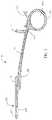
- FIG. 1is a side, perspective view of a radiofrequency (RF) surgical system including a surgical forceps and an electrosurgical generator in accordance with the present disclosure
- RFradiofrequency
- FIG. 2is a longitudinal, cross-sectional view of one of the shaft members of the surgical forceps of FIG. 1 ;
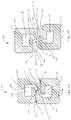
- FIG. 3 Ais a transverse, cross-sectional view of jaw members of the surgical forceps of FIG. 1 , disposed in a closed position;
- FIG. 3 Bis a transverse, cross-sectional view of the jaw members of the surgical forceps of FIG. 1 , disposed in a cutting position;
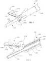
- FIG. 4is a side, perspective view of an ultrasonic surgical instrument including an onboard generator and battery in accordance with the present disclosure
- FIG. 5is an enlarged, perspective view of a distal end portion of the ultrasonic surgical instrument of FIG. 4 ;
- FIG. 6is a perspective, longitudinal, cross-sectional view of the distal end portion of the ultrasonic surgical instrument of FIG. 4 ;
- FIG. 7 Ais a side view of a jaw member of the ultrasonic surgical instrument of FIG. 4 ;
- FIG. 7 Bis a bottom view of the jaw member of FIG. 7 A ;
- FIG. 7 Cis a proximal end view of the jaw member of FIG. 7 A ;
- FIG. 8is a longitudinal, cross-sectional view of a waveguide of the ultrasonic surgical instrument of FIG. 4 .
- the present disclosurerelates to energy-based surgical instruments configured to reduce or eliminate thermal spread.
- An exemplary radiofrequency (RF) surgical forceps 100 ( FIG. 1 ) and an exemplary ultrasonic surgical instrument 1000 ( FIG. 4 )are detailed herein exemplifying the aspects and features of the present disclosure; however, the present disclosure is equally applicable for use with any suitable energy-based surgical instrument.
- RF surgical forceps 100 ( FIG. 1 )is shown as a hemostat-style instrument and ultrasonic surgical instrument 1000 ( FIG. 4 ) is shown as a shaft-based instrument, this configuration may be reversed, e.g., wherein the RF instrument is of a shaft-based style and the ultrasonic surgical instrument is of a hemostat-style.
- different electrical and mechanical considerationsapply to each particular type and/or style of instrument; however, the aspects and features of the present disclosure remain generally consistent regardless of the particular energy-based surgical instrument used.
- RF surgical forceps 100provided in accordance with the present disclosure includes first and second shaft members 110 , 120 each having a proximal end portion 112 a , 122 a and a distal end portion 112 b , 122 b , respectively.
- An end effector assembly 200 of forceps 100includes first and second jaw members 210 , 220 extending from distal end portions 112 b , 122 b of shaft members 110 , 120 , respectively.
- Forceps 100further includes a pivot 130 pivotably coupling first and second shaft members 110 , 120 with one another, and a housing 150 engaged with the proximal end portion of one of the shaft members, e.g., proximal end portion 112 a of shaft member 110 .
- a cable 152extends from housing 150 to couple forceps 100 to an electrosurgical generator (not shown) to enable the supply of RF energy to forceps 100
- tubes 119 , 129extend from proximal end portions 112 a , 122 a , respectively, of shaft members 110 , 120 , respectively, to couple forceps 100 to a vacuum source 300 , as detailed below.
- the electrosurgical generator and vacuum source 300may be provided as a single unit.
- the electrosurgical generator and/or vacuum source 300may be remote from forceps 100 or may be mounted thereon or therein.
- Shaft members 110 , 120are formed at least partially from an electrically-conductive material such that electrosurgical energy may be transmitted therealong to and from jaw members 210 , 220 , respectively.
- shaft members 110 , 120may house conductors (not shown) configured to transmit electrosurgical energy to and from jaw members 210 , 220 .
- Proximal end portions 112 a , 122 a of shaft members 110 , 120respectively, include handles 115 a , 125 a defining finger holes 115 b , 125 b configured to facilitate grasping and manipulating shaft members 110 , 120 .
- Distal end portions 112 b , 122 b of shaft members 110 , 120form uprights 116 , 126 defining apertures configured to receive pivot 130 therethrough for pivotably coupling distal end portions 112 b , 122 b of shaft members 110 , 120 with one another.
- handles 115 a , 125 aare movable relative to one another in directions substantially perpendicular to a pivot axis of pivot 130 to move shaft members 110 , 120 between a spaced-apart position and an approximated position to thereby pivot jaw members 210 , 220 about pivot 130 and relative to one another between an open position ( FIG. 1 ) and a closed position ( FIG. 3 A ).
- Handles 115 a , 125 aare further movable relative to one another in directions substantially parallel to the pivot axis of pivot pin 130 to move shaft members 110 , 120 from the approximated position to a yawed position to thereby move jaw members 210 , 220 from the closed position ( FIG. 3 A ) to a cutting position ( FIG. 3 B ).
- housing 150is mounted, e.g., releasably mounted, on proximal end portion 112 a of shaft member 110 and includes cable 152 extending proximally from therefrom and a switch assembly 154 having an activation button 155 extending from housing 150 towards shaft member 120 .
- Cable 152includes a plug 158 disposed at the free proximal end portion thereof to enable connection of forceps 100 to a source of energy (not shown), e.g., an electrosurgical generator.
- a plurality of electrical lead wiresextend through cable 152 and into housing 150 , communicating with switch assembly 154 and first and second electrical contacts (not shown) disposed within housing 152 .
- the first electrical contactis disposed in electrical communication with shaft member 110 to establish electrical communication between one or more of the plurality of electrical lead wires and first jaw member 210
- the second electrical contactis positioned such that, in the approximated position of shaft members 110 , 120 , respectively, an electrical connection pin 123 of shaft member 120 contacts the second electrical contact to establish electrical communication between one or more of the plurality of electrical lead wires and second jaw member 220 .
- other suitable electrical connection arrangementsare also contemplated.
- Switch assembly 154is positioned such that, upon movement of shaft members 110 , 120 to the approximated position, handle 125 a of shaft member 120 is sufficiently urged into contact with activation button 155 to actuate activation button 155 .
- One of more of the plurality of electrical lead wiresis coupled to switch assembly 154 , thus enabling initiation of the supply of RF energy to jaw members 210 , 220 of end effector assembly 200 upon actuation of activation button 155 of switch assembly 154 , e.g., for treating tissue grasped between jaw members 210 , 220 .
- each shaft member 110 , 120defines a lumen 118 , 128 extending longitudinally therethrough from proximal end portion 112 a , 122 a , through distal end portion 112 b , 122 b , respectively, thereof, and into the respective jaw member 210 , 220 thereof.
- shaft member 120 and lumen 128 thereofare illustrated in FIG. 2 , it is understood that shaft member 110 defines a similar configuration.
- Lumens 118 , 128communicate with respective tubes 119 , 129 at the proximal end portions 112 a , 122 a of shaft members 110 , 120 , respectively, such that lumens 118 , 128 are disposed in operable communicate with vacuum source 300 .
- vacuum source 300when vacuum source 300 is activated, a vacuum is applied through tubes 119 , 129 and, thus, through lumens 118 , 128 .
- End effector assembly 200includes first and second jaw members 210 , 220 pivotable relative to one another between the open position ( FIG. 1 ) and the closed position ( FIG. 3 A ). Jaw members 210 , 220 are further movable, as also noted above, to a cutting position ( FIG. 3 B ).
- Each jaw member 210 , 220includes a body 212 , 222 defining a first tissue-contacting surface portion 214 , 224 , a step 216 , 226 extending from the respective body 212 , 222 towards the other jaw members 210 , 220 , and a second tissue-contact surface portion 218 , 228 , respectively offset relative to the respective first tissue-contacting surface portion 214 , 224 via the respective step 216 , 226 .
- Steps 216 , 226 of jaw members 210 , 220include walls 217 , 227 , respectively, interconnecting respective first and second tissue-contacting surface portions 114 , 124 and 214 , 224 , of respective jaw members 210 , 220 with one another. Walls 217 , 227 extend in generally perpendicular orientation relative to each of the first and second tissue-contacting surface portions 114 , 124 and 214 , 224 , respectively, of the corresponding jaw member 210 , 220 .
- Steps 216 , 226are laterally offset relative to one another such that, in an aligned orientation of jaw members 210 , 220 , second tissue-contact surface portion 218 of jaw member 210 opposes a portion of first tissue-contacting surface portion 224 of jaw member 220 and such that second tissue-contact surface portion 228 of jaw member 220 opposes a portion of first tissue-contacting surface portion 214 of jaw member 210 .
- first tissue-contacting surface portions 214 , 224define greater widths as compared to second tissue-contacting surface portions 218 , 228 such that the portions of first tissue-contacting surface portions 214 , 224 extending between steps 216 , 226 also oppose one another.
- Walls 217 , 227 of steps 216 , 226define openings 219 , 229 therethrough in communication with lumens 118 , 128 .
- tissue-contacting surface portions 214 , 218 and 224 , 228are uninterrupted.
- Each opening 219 , 229may be defined as a slot extending along the length of the respective step 216 , 226 , or may define a plurality of apertures spaced-apart along the length of the respective step 216 , 226 .
- Other configurationsare also contemplated.
- Vacuum source 300may include a collection reservoir 310 , or a separate collection reservoir (not shown) may be provided, to collect any fluids and tissue debris aspirated from the surgical site via openings 219 , 229 .
- jaw members 210 , 220are disposed in the open position of wherein jaw members 210 , 220 are spaced-apart from one another and disposed in an aligned orientation relative to one another.
- forceps 100may be manipulated such that tissue to be grasped, treated, and/or divided is disposed between jaw members 210 , 220 .
- shaft members 110 , 120may be moved relative to one another in directions substantially perpendicular to the pivot axis of pivot 130 from the spaced-apart position to the approximated position to pivot jaw members 210 , 220 about pivot 130 and relative to one another from the open position ( FIG. 1 ) to the closed position ( FIG. 3 A ).
- jaw members 210 , 220are approximated relative to one another but maintained in the aligned orientation.
- second tissue-contact surface portion 218 of jaw member 210is approximated relative to the opposing portion of first tissue-contacting surface portion 224 of jaw member 220 and second tissue-contact surface portion 228 of jaw member 220 is approximated relative to the opposing portion of first tissue-contacting surface portion 214 of jaw member 210 .
- Movement of jaw members 210 , 220 between the open and closed positionsmay be effectuated in order to grasp and/or manipulate tissue.
- RF energymay be conducted between jaw members 210 , 220 to treat tissue grasped therebetween, e.g., upon actuation of activation button 155 ( FIG. 1 ).
- RF energyis conducted between second tissue-contact surface portion 218 of jaw member 210 and the opposing portion of first tissue-contacting surface portion 224 of jaw member 220 to treat, e.g., seal, tissue therebetween, and between second tissue-contact surface portion 228 of jaw member 220 and the opposing portion of first tissue-contacting surface portion 214 of jaw member 210 to treat, e.g., seal, tissue therebetween.
- RF energymay also be conducted transversely across the portions of first tissue-contacting surface portions 214 , 224 extending between steps 216 , 226 to treat, e.g., seal, tissue disposed therebetween.
- tissue grasped between jaw members 210 , 220is heated and, as a by-product thereof, high pressure and temperature steam may be produced.
- the high pressure and temperature steammay escape the area between jaw members 210 , 220 and potentially thermally damage surrounding tissue. This is known as thermal spread.
- vacuum source 300may be activated to apply vacuum through tubes 119 , 129 , lumens 118 , 128 , and thus, at openings 219 , 229 .
- Vacuum source 300may be activated automatically upon activation of switch assembly 154 , or manually.
- shaft members 110 , 120may be moved relative to one another in directions substantially parallel to the pivot axis of pivot 130 from the approximated position to the yawed position to move jaw members 210 , 220 relative to one another from the closed position ( FIG. 3 A ) to the cutting position ( FIG. 3 B ). In this manner, a shearing action between steps 216 , 226 is effected to cut tissue disposed therebetween.
- one or both of jaw members 210 , 220may define a knife channel (not shown) configured to enable reciprocation of a knife (not shown) therethrough.
- openings 219 , 229may be defined through the walls defining the knife channel.
- ultrasonic surgical instrument 1000generally includes a handle assembly 1100 , an elongated assembly 1200 extending distally from handle assembly 1100 , an ultrasonic transducer and generator assembly (“TAG”) 1300 configured for releasable engagement with handle assembly 1100 , a battery assembly 1400 configured for releasable receipt within handle assembly 1100 , and a vacuum system 1500 operably disposed within or mounted on handle assembly 1100 .
- TAGultrasonic transducer and generator assembly
- battery assembly 1400configured for releasable receipt within handle assembly 1100
- a vacuum system 1500operably disposed within or mounted on handle assembly 1100 .
- ultrasonic surgical instrument 1000is configured as a cordless, hand-held device.
- the present disclosureis equally applicable for use with corded ultrasonic surgical instruments configured to connect to a remote generator and/or vacuum source.
- Handle assembly 1100includes a housing 1110 defining a body portion 1112 configured to enable releasable mounting of TAG 1300 thereon and a fixed handle portion 1114 depending from body portion 1112 .
- Fixed handle portion 1114defines a battery compartment 1116 including a door 1118 configured to enable releasable receipt and enclosure of battery assembly 1400 within fixed handle portion 1114 .
- Handle assembly 1100further includes an activation button 1120 operably positioned to electrically couple between TAG 1300 and battery assembly 1400 when TAG 1300 is mounted on body portion 1112 of housing 1110 and battery assembly 1400 is enclosed within compartment 1116 of fixed handle portion 1114 of housing 1110 to enable selective energization of ultrasonic surgical instrument 1000 , as detailed below.
- a clamp trigger 1130extends from housing 1110 of handle assembly 1100 adjacent fixed handle portion 1114 of housing 1110 .
- Clamp trigger 1130includes a drive portion (not shown) extending into body portion 1112 of housing 1110 and operably coupled to a drive assembly (not shown) to enable actuation of ultrasonic surgical instrument 1000 in response to actuation of clamp trigger 1130 relative to fixed handle portion 1114 of housing 1110 , as detailed below.
- elongated assembly 1200 of ultrasonic surgical instrument 1000includes a waveguide 1210 which extends from housing 1110 to an end effector 1220 disposed at the distal end portion of elongated assembly 1200 .
- Elongated assembly 1200further includes an outer shaft 1230 and an inner shaft 1240 .
- Waveguide 1210includes a body portion 1212 that extends through housing 1110 and shafts 1230 , 1240 and a distal end portion that extends distally from shafts 1230 , 1240 and defines blade 1222 of end effector 1220 .
- Waveguide 1210further defines a lumen 1223 extending longitudinally therethrough, as detailed below.
- a proximal end portion of lumen 1223is disposed in communication, e.g., via one or more tubes, seals, and/or other connectors (not shown), with vacuum system 1500 .
- vacuum system 1500upon activation of vacuum system 1500 , negative pressure is created within lumen 1223 .
- Vacuum system 1500may include a collection reservoir 1510 , or a separate collection reservoir (not shown) may be provided, to collect any fluids and tissue debris aspirated from the surgical site through lumen 1223 , as detailed below.
- the proximal end portion of body portion 1212 of waveguide 1210includes features, e.g., threading, configured to enable operable engagement thereof with TAG 1300 , e.g., with a female threaded receiver of the transducer of TAG 1300 .
- Outer shaft 1230 and inner shaft 1240may cooperate to define a longitudinally-extending annular channel therebetween or may include a longitudinally-extending tube 1235 disposed in the annular space defined therebetween (as shown).
- a proximal end portion of tube 1235is disposed in communication, e.g., directly or via one or more tubes, seals, and/or other connectors (not shown), with vacuum system 1500 .
- tube 1235upon activation of vacuum system 1500 , negative pressure is created within tube 1235 .
- Outer shaft 1230is slidably disposed about inner shaft 1240 and waveguide 1210 and extends between housing 1110 and end effector 1220 .
- Inner shaft 1240is longitudinally fixed relative to housing 1110 and end effector 1220 .
- a rotating assembly 1250is rotatably mounted on housing 1110 and operably coupled to elongated assembly 1200 so as to enable rotation of elongated assembly 1200 and, thus, end effector 1220 relative to housing 1110 upon rotation of rotation wheel 1252 of rotating assembly 1250 relative to housing 1110 .
- End effector 1220is disposed at a distal end portion of elongated assembly 1200 and includes blade 1222 of waveguide 1210 and a jaw member 1224 .
- Jaw member 1224is pivotable supported at a distal end portion of inner shaft 1240 and is pivotable relative to blade 1222 between an open position, wherein jaw member 1224 is spaced-apart from blade 1222 , and a closed position, wherein jaw member 1224 is approximated relative to blade 1222 in juxtaposed alignment therewith for clamping tissue therebetween.
- jaw member 1224includes a structural body 1225 and a jaw liner 1226 secured to structural body 1225 .
- Structural body 1225may be formed from a rigid material and includes a proximal flange portion 1225 a and an elongated distal portion 1225 b extending distally from proximal flange portion 1225 a .
- Proximal flange portion 1225 aincludes pivot bosses 1225 c to enable pivotable coupling of jaw member 1224 with inner shaft 1240 .
- Proximal flange portion 1225 afurther includes feet 1225 d that enable operable coupling of jaw member 1224 with the distal end portion of outer shaft 1230 such that sliding of outer shaft 1230 about inner shaft 1240 pivots jaw member 1224 relative to blade 1222 between the open position and the closed position.
- Outer shaft 1230is operably coupled to clamp trigger 1130 by way of the drive assembly (not shown) such that, in response to actuation of clamp trigger 1130 relative to fixed handle portion 1114 of housing 1110 of handle assembly 1100 , jaw member 1224 is pivoted relative to blade 1222 between the open position and the closed position.
- Jaw liner 1226may be formed from a compliant material and is positioned to oppose blade 1222 such that blade 1222 is inhibited from contacting structural body 1225 of jaw member 1224 . As a result, the transfer of ultrasonic vibrations and/or thermal energy from blade 1222 to structural body 1225 during use is reduced.
- Jaw liner 1226defines a tissue-contacting surface 1226 a and may include a plurality of gripping teeth 1226 b disposed along the length of tissue-contacting surface 1226 a . Jaw liner 1226 further defines a lumen 1226 c extending longitudinally therethrough having a closed distal end. Lumen 1226 c defines an open proximal end 1226 d disposed in communication with tube 1235 , e.g., directly or via one or more tubes, seals, and/or other connectors (not shown). A plurality of openings 1226 e defined through tissue-contacting surface 1226 a along the length thereof in spaced-apart relation relative to one another are disposed in communication with lumen 1226 c .
- openings 1226 edisposed in communication with lumen 1226 c which, in turn, is disposed in communication with tube 1235
- negative pressureis created within tube 1235 and lumen 1226 c so as to provide aspiration through openings 1226 e , lumen 1226 c , and tube 1235 .
- blade 1222is configured to serve as an active or oscillating ultrasonic member that is selectively activatable to ultrasonically treat tissue grasped between blade 1222 and jaw liner 1226 of jaw member 1224 .
- Blade 1222may be formed to define a straight configuration or, alternatively, a curved configuration.
- Lumen 1223 of waveguide 1210extends at least partially through blade 1222 and defines a closed distal end portion.
- a plurality of openings 1228are defined through the tissue-contacting surface of blade 1222 oriented towards jaw member 1224 . Openings 1228 are disposed along the length of blade 1222 in spaced-apart relation relative to one another and are disposed in communication with lumen 1223 . With openings 1228 disposed in communication with lumen 1223 , upon activation of vacuum system 1500 ( FIG. 4 ), negative pressure is created within lumen 1223 so as to provide aspiration through openings 1228 and lumen 1223 .
- TAG 1300is configured to convert electrical energy provided by battery assembly 1400 into mechanical energy that is transmitted along waveguide 1210 to blade 1222 . More specifically, TAG 1300 is configured to convert the electrical energy provided by battery assembly 1400 into a high voltage alternating current (AC) waveform that drives the transducer (not shown) of TAG 1300 .
- Activation button 1120 of handle assembly 1100is electrically coupled between battery assembly 1400 and TAG 1300 . Activation button 1120 is selectively activatable in a first position and a second position to supply electrical energy from battery assembly 1400 to TAG 1300 for operating ultrasonic surgical instrument 1000 in a low-power mode of operation and a high-power mode of operation, respectively.
- ultrasonic surgical instrument 1000may be manipulated such that tissue to be treated, e.g., coagulated and/or dissected, is disposed between blade 1222 and jaw member 1224 .
- clamp trigger 1130may be actuated towards fixed handle portion 1114 of housing 1110 to pivot jaw member 1224 from the open position towards the closed position to grasp and/or manipulate tissue.
- activation button 1120may be activated to supply electrical energy from battery assembly 1400 to TAG 1300 such that TAG 1300 converts the electrical energy into ultrasonic energy that is transmitted along waveguide 1210 to blade 1222 .
- the ultrasonic energy transmitted to blade 1222ultrasonically vibrates blade 1222 to generate heat, thereby treating tissue grasped between blade 1222 and jaw member 1224 .
- high pressure and temperature steammay be produced and may escape, creating thermal spread.
- vacuum system 1500may be activated to apply vacuum through tube 1235 and lumen 1223 and, thus, at openings 1226 e and 1228 , respectively.
- Vacuum system 1500may be activated automatically upon activation of activation button 1120 , or manually.
- jaw member 1224may be returned to the open position to release the treated tissue.
Landscapes
- Health & Medical Sciences (AREA)
- Surgery (AREA)
- Engineering & Computer Science (AREA)
- Life Sciences & Earth Sciences (AREA)
- Biomedical Technology (AREA)
- Public Health (AREA)
- Nuclear Medicine, Radiotherapy & Molecular Imaging (AREA)
- Veterinary Medicine (AREA)
- General Health & Medical Sciences (AREA)
- Heart & Thoracic Surgery (AREA)
- Medical Informatics (AREA)
- Molecular Biology (AREA)
- Animal Behavior & Ethology (AREA)
- Physics & Mathematics (AREA)
- Otolaryngology (AREA)
- Plasma & Fusion (AREA)
- Dentistry (AREA)
- Mechanical Engineering (AREA)
- Surgical Instruments (AREA)
Abstract
Description
Claims (18)
Applications Claiming Priority (1)
| Application Number | Priority Date | Filing Date | Title |
|---|---|---|---|
| PCT/CN2017/098435WO2019036896A1 (en) | 2017-08-22 | 2017-08-22 | Energy-based surgical instruments and systems configured to minimize thermal spread |
Related Parent Applications (1)
| Application Number | Title | Priority Date | Filing Date |
|---|---|---|---|
| PCT/CN2017/098435A-371-Of-InternationalWO2019036896A1 (en) | 2017-08-22 | 2017-08-22 | Energy-based surgical instruments and systems configured to minimize thermal spread |
Related Child Applications (1)
| Application Number | Title | Priority Date | Filing Date |
|---|---|---|---|
| US17/992,978DivisionUS20230096146A1 (en) | 2017-08-22 | 2022-11-23 | Energy-based surgical instruments and systems configured to minimize thermal spread |
Publications (2)
| Publication Number | Publication Date |
|---|---|
| US20210212751A1 US20210212751A1 (en) | 2021-07-15 |
| US11534231B2true US11534231B2 (en) | 2022-12-27 |
Family
ID=63350369
Family Applications (2)
| Application Number | Title | Priority Date | Filing Date |
|---|---|---|---|
| US16/070,003Active2040-12-06US11534231B2 (en) | 2017-08-22 | 2017-08-22 | Energy-based surgical instruments and systems configured to minimize thermal spread |
| US17/992,978PendingUS20230096146A1 (en) | 2017-08-22 | 2022-11-23 | Energy-based surgical instruments and systems configured to minimize thermal spread |
Family Applications After (1)
| Application Number | Title | Priority Date | Filing Date |
|---|---|---|---|
| US17/992,978PendingUS20230096146A1 (en) | 2017-08-22 | 2022-11-23 | Energy-based surgical instruments and systems configured to minimize thermal spread |
Country Status (4)
| Country | Link |
|---|---|
| US (2) | US11534231B2 (en) |
| EP (1) | EP3446653B1 (en) |
| CN (1) | CN109419552B (en) |
| WO (1) | WO2019036896A1 (en) |
Families Citing this family (3)
| Publication number | Priority date | Publication date | Assignee | Title |
|---|---|---|---|---|
| US20220296415A1 (en)* | 2021-03-22 | 2022-09-22 | Tarek Hassan | Suction forceps |
| US20220313300A1 (en)* | 2021-04-02 | 2022-10-06 | Stryker European Operations Limited | Methods And Systems For Analyzing Surgical Smoke Using Atomic Absorption Spectroscopy |
| CN117045314A (en)* | 2023-09-26 | 2023-11-14 | 上海圣哲医疗科技有限公司 | Surgical knife |
Citations (52)
| Publication number | Priority date | Publication date | Assignee | Title |
|---|---|---|---|---|
| US3916909A (en)* | 1973-08-01 | 1975-11-04 | Bio Medicus Inc | Suction surgical instrument of the forceps type |
| US4074718A (en)* | 1976-03-17 | 1978-02-21 | Valleylab, Inc. | Electrosurgical instrument |
| US4096864A (en)* | 1975-03-26 | 1978-06-27 | Bio-Medicus, Inc. | Fluid carrying surgical instrument of the forceps type |
| US4681561A (en) | 1986-01-24 | 1987-07-21 | Coopervision, Inc. | Ultrasonic decoupling sleeve |
| JPS62177415A (en) | 1986-01-31 | 1987-08-04 | Kawasaki Steel Corp | Flow rate measuring instrument |
| US4724834A (en) | 1985-11-20 | 1988-02-16 | Tomsky Gosudarstvenny Meditsinsky Institut | Cryogenic-and-ultrasonic scalpel |
| JPH01151452A (en) | 1987-12-09 | 1989-06-14 | Olympus Optical Co Ltd | Ultrasonic suction apparatus |
| EP0514810A1 (en) | 1991-05-22 | 1992-11-25 | Antonio La Rosa | Ultrasonic dissector and detacher for atherosclerotic plaques |
| US5190541A (en)* | 1990-10-17 | 1993-03-02 | Boston Scientific Corporation | Surgical instrument and method |
| US5217460A (en)* | 1991-03-22 | 1993-06-08 | Knoepfler Dennis J | Multiple purpose forceps |
| US5250075A (en)* | 1992-09-02 | 1993-10-05 | Behnam Badie | Bayonet sucker forceps |
| US5383876A (en) | 1992-11-13 | 1995-01-24 | American Cardiac Ablation Co., Inc. | Fluid cooled electrosurgical probe for cutting and cauterizing tissue |
| US5391144A (en) | 1990-02-02 | 1995-02-21 | Olympus Optical Co., Ltd. | Ultrasonic treatment apparatus |
| US5603712A (en)* | 1995-06-05 | 1997-02-18 | Frank C. Koranda | Bipola suction tonsillar dissector |
| US5797958A (en)* | 1989-12-05 | 1998-08-25 | Yoon; Inbae | Endoscopic grasping instrument with scissors |
| US6206876B1 (en) | 1995-03-10 | 2001-03-27 | Seedling Enterprises, Llc | Electrosurgery with cooled electrodes |
| US6379371B1 (en) | 1999-11-15 | 2002-04-30 | Misonix, Incorporated | Ultrasonic cutting blade with cooling |
| US20020091404A1 (en) | 2001-01-08 | 2002-07-11 | Beaupre Jean M. | Laminated ultrasonic waveguides fabricated from sheet stock |
| US20030181904A1 (en) | 2002-01-23 | 2003-09-25 | Levine Andy H. | Electrosurgical cutting, coagulating and suction instrument |
| US20030204199A1 (en) | 2002-04-30 | 2003-10-30 | Novak Theodore A. D. | Device and method for ultrasonic tissue excision with tissue selectivity |
| US6764487B2 (en) | 1995-02-22 | 2004-07-20 | Medtronic, Inc. | Fluid-assisted electrosurgical device |
| JP2005160735A (en) | 2003-12-02 | 2005-06-23 | Olympus Corp | Controller for medical apparatus |
| US6939350B2 (en) | 2001-10-22 | 2005-09-06 | Boston Scientific Scimed, Inc. | Apparatus for supporting diagnostic and therapeutic elements in contact with tissue including electrode cooling device |
| US20050209578A1 (en) | 2004-01-29 | 2005-09-22 | Christian Evans Edward A | Ultrasonic catheter with segmented fluid delivery |
| US7074219B2 (en) | 1995-03-10 | 2006-07-11 | Ethicon Endo-Surgery, Inc. | Electrosurgery with cooled electrodes |
| US20060265035A1 (en)* | 2005-05-13 | 2006-11-23 | Olympus Medical Systems Corp. | Medical treatment instrument, water supply / suction system for medical treatment instrument |
| US20070233054A1 (en) | 2005-10-13 | 2007-10-04 | Bacoustics, Llc | Apparatus and methods for the selective removal of tissue |
| US20080015563A1 (en) | 1995-02-22 | 2008-01-17 | Hoey Michael F | Apparatus and method for creating, maintaining, and controlling a virtual electrode used for the ablation of tissue |
| JP4089043B2 (en) | 1998-10-20 | 2008-05-21 | 日立化成工業株式会社 | Planar antenna for beam scanning |
| US20090036914A1 (en) | 2007-07-31 | 2009-02-05 | Houser Kevin L | Temperature controlled ultrasonic surgical instruments |
| CN101511286A (en) | 2005-10-14 | 2009-08-19 | 伊西康内外科公司 | Ultrasonic device for cutting and coagulating |
| US20100087814A1 (en)* | 2006-06-08 | 2010-04-08 | Kai Desinger | Device for cutting and coagulating tissue |
| US20100087816A1 (en)* | 2008-10-07 | 2010-04-08 | Roy Jeffrey M | Apparatus, system, and method for performing an electrosurgical procedure |
| CN201939898U (en) | 2011-01-10 | 2011-08-24 | 武汉亚格光电技术有限公司 | Cooling-type ultrasonic therapeutic head |
| US20120078278A1 (en) | 2007-12-03 | 2012-03-29 | Bales Jr Thomas O | Battery-Powered Hand-Held Ultrasonic Surgical Cautery Cutting Device |
| US20120253371A1 (en) | 2011-03-30 | 2012-10-04 | Tyco Healthcare Group Lp | Ultrasonic surgical instruments |
| US8348880B2 (en)* | 2001-04-04 | 2013-01-08 | Ethicon Endo-Surgery, Inc. | Ultrasonic surgical instrument incorporating fluid management |
| US20130046337A1 (en) | 2011-08-18 | 2013-02-21 | Tyco Healthcare Group Lp | Surgical Forceps |
| US20130072950A1 (en) | 2011-09-20 | 2013-03-21 | Tyco Healthcare Group Lp | Ultrasonic Surgical System Having A Fluid Cooled Blade And Related Cooling Methods Therefor |
| US20130178842A1 (en) | 2012-01-05 | 2013-07-11 | Vivant Medical, Inc. | Ablation Systems, Probes, and Methods for Reducing Radiation from an Ablation Probe into the Environment |
| JP2014000311A (en) | 2012-06-20 | 2014-01-09 | Olympus Corp | Ultrasonic treatment instrument |
| US20140276369A1 (en) | 2008-06-26 | 2014-09-18 | Surgical Design Corporation | Surgical hand piece with rotatable dual lumen work tip |
| WO2014196226A1 (en) | 2013-06-04 | 2014-12-11 | オリンパス株式会社 | Ultrasonic treatment instrument |
| US20150080876A1 (en)* | 2013-09-16 | 2015-03-19 | Ethoicon Endo-Surgery, Inc | Integrated systems for electrosurgical steam or smoke control |
| US20150141980A1 (en) | 2013-11-19 | 2015-05-21 | Covidien Lp | Vessel sealing instrument with suction system |
| US9138285B2 (en)* | 2012-06-19 | 2015-09-22 | Sutter Medizintechnik Gmbh | Coagulation forceps with a tubular shaft |
| US9173707B2 (en)* | 2012-09-27 | 2015-11-03 | City Of Hope | Coaptive surgical sealing tool |
| US20170105752A1 (en)* | 2015-10-20 | 2017-04-20 | Ethicon Endo-Surgery, Llc | Surgical instrument providing ultrasonic tissue emulsification and ultrasonic shearing |
| US20170105789A1 (en)* | 2015-10-16 | 2017-04-20 | Ethicon Endo-Surgery, Llc | Suction and irrigation sealing grasper |
| US9764166B2 (en) | 2013-09-11 | 2017-09-19 | Covidien Lp | Ultrasonic surgical instrument with cooling system |
| US9788882B2 (en)* | 2011-09-08 | 2017-10-17 | Arthrocare Corporation | Plasma bipolar forceps |
| US10987159B2 (en)* | 2015-08-26 | 2021-04-27 | Covidien Lp | Electrosurgical end effector assemblies and electrosurgical forceps configured to reduce thermal spread |
Family Cites Families (8)
| Publication number | Priority date | Publication date | Assignee | Title |
|---|---|---|---|---|
| DE19629278C2 (en)* | 1996-07-19 | 2001-07-05 | Storz Karl Gmbh & Co Kg | Instrument for cutting tissue with HF current |
| US20020111624A1 (en)* | 2001-01-26 | 2002-08-15 | Witt David A. | Coagulating electrosurgical instrument with tissue dam |
| US20060079879A1 (en)* | 2004-10-08 | 2006-04-13 | Faller Craig N | Actuation mechanism for use with an ultrasonic surgical instrument |
| US20090024126A1 (en)* | 2007-07-19 | 2009-01-22 | Ryan Artale | Tissue fusion device |
| US8795327B2 (en)* | 2010-07-22 | 2014-08-05 | Ethicon Endo-Surgery, Inc. | Electrosurgical instrument with separate closure and cutting members |
| US20120253339A1 (en)* | 2011-03-31 | 2012-10-04 | Tyco Healthcare Group Lp | Radio frequency-based surgical implant fixation apparatus |
| US9913655B2 (en)* | 2013-11-18 | 2018-03-13 | Ethicon Llc | Surgical instrument with active element and suction cage |
| US10758257B2 (en)* | 2015-04-24 | 2020-09-01 | Covidien Lp | Vessel sealing device with fine dissection function |
- 2017
- 2017-08-22USUS16/070,003patent/US11534231B2/enactiveActive
- 2017-08-22WOPCT/CN2017/098435patent/WO2019036896A1/ennot_activeCeased
- 2018
- 2018-08-21EPEP18189867.7Apatent/EP3446653B1/enactiveActive
- 2018-08-22CNCN201810957180.0Apatent/CN109419552B/enactiveActive
- 2022
- 2022-11-23USUS17/992,978patent/US20230096146A1/enactivePending
Patent Citations (56)
| Publication number | Priority date | Publication date | Assignee | Title |
|---|---|---|---|---|
| US3916909A (en)* | 1973-08-01 | 1975-11-04 | Bio Medicus Inc | Suction surgical instrument of the forceps type |
| US4096864A (en)* | 1975-03-26 | 1978-06-27 | Bio-Medicus, Inc. | Fluid carrying surgical instrument of the forceps type |
| US4074718A (en)* | 1976-03-17 | 1978-02-21 | Valleylab, Inc. | Electrosurgical instrument |
| US4724834A (en) | 1985-11-20 | 1988-02-16 | Tomsky Gosudarstvenny Meditsinsky Institut | Cryogenic-and-ultrasonic scalpel |
| US4681561A (en) | 1986-01-24 | 1987-07-21 | Coopervision, Inc. | Ultrasonic decoupling sleeve |
| JPS62177415A (en) | 1986-01-31 | 1987-08-04 | Kawasaki Steel Corp | Flow rate measuring instrument |
| JPH01151452A (en) | 1987-12-09 | 1989-06-14 | Olympus Optical Co Ltd | Ultrasonic suction apparatus |
| US5797958A (en)* | 1989-12-05 | 1998-08-25 | Yoon; Inbae | Endoscopic grasping instrument with scissors |
| US5391144A (en) | 1990-02-02 | 1995-02-21 | Olympus Optical Co., Ltd. | Ultrasonic treatment apparatus |
| US5190541A (en)* | 1990-10-17 | 1993-03-02 | Boston Scientific Corporation | Surgical instrument and method |
| US5217460A (en)* | 1991-03-22 | 1993-06-08 | Knoepfler Dennis J | Multiple purpose forceps |
| EP0514810A1 (en) | 1991-05-22 | 1992-11-25 | Antonio La Rosa | Ultrasonic dissector and detacher for atherosclerotic plaques |
| US5250075A (en)* | 1992-09-02 | 1993-10-05 | Behnam Badie | Bayonet sucker forceps |
| US5383876A (en) | 1992-11-13 | 1995-01-24 | American Cardiac Ablation Co., Inc. | Fluid cooled electrosurgical probe for cutting and cauterizing tissue |
| US6764487B2 (en) | 1995-02-22 | 2004-07-20 | Medtronic, Inc. | Fluid-assisted electrosurgical device |
| US20080015563A1 (en) | 1995-02-22 | 2008-01-17 | Hoey Michael F | Apparatus and method for creating, maintaining, and controlling a virtual electrode used for the ablation of tissue |
| US6206876B1 (en) | 1995-03-10 | 2001-03-27 | Seedling Enterprises, Llc | Electrosurgery with cooled electrodes |
| US7074219B2 (en) | 1995-03-10 | 2006-07-11 | Ethicon Endo-Surgery, Inc. | Electrosurgery with cooled electrodes |
| US5603712A (en)* | 1995-06-05 | 1997-02-18 | Frank C. Koranda | Bipola suction tonsillar dissector |
| JP4089043B2 (en) | 1998-10-20 | 2008-05-21 | 日立化成工業株式会社 | Planar antenna for beam scanning |
| US6379371B1 (en) | 1999-11-15 | 2002-04-30 | Misonix, Incorporated | Ultrasonic cutting blade with cooling |
| US20020091404A1 (en) | 2001-01-08 | 2002-07-11 | Beaupre Jean M. | Laminated ultrasonic waveguides fabricated from sheet stock |
| US8348880B2 (en)* | 2001-04-04 | 2013-01-08 | Ethicon Endo-Surgery, Inc. | Ultrasonic surgical instrument incorporating fluid management |
| US6939350B2 (en) | 2001-10-22 | 2005-09-06 | Boston Scientific Scimed, Inc. | Apparatus for supporting diagnostic and therapeutic elements in contact with tissue including electrode cooling device |
| US20030181904A1 (en) | 2002-01-23 | 2003-09-25 | Levine Andy H. | Electrosurgical cutting, coagulating and suction instrument |
| US20030204199A1 (en) | 2002-04-30 | 2003-10-30 | Novak Theodore A. D. | Device and method for ultrasonic tissue excision with tissue selectivity |
| JP2005160735A (en) | 2003-12-02 | 2005-06-23 | Olympus Corp | Controller for medical apparatus |
| US20050209578A1 (en) | 2004-01-29 | 2005-09-22 | Christian Evans Edward A | Ultrasonic catheter with segmented fluid delivery |
| US20060265035A1 (en)* | 2005-05-13 | 2006-11-23 | Olympus Medical Systems Corp. | Medical treatment instrument, water supply / suction system for medical treatment instrument |
| US20070233054A1 (en) | 2005-10-13 | 2007-10-04 | Bacoustics, Llc | Apparatus and methods for the selective removal of tissue |
| CN101511286A (en) | 2005-10-14 | 2009-08-19 | 伊西康内外科公司 | Ultrasonic device for cutting and coagulating |
| US20100087814A1 (en)* | 2006-06-08 | 2010-04-08 | Kai Desinger | Device for cutting and coagulating tissue |
| WO2009032438A2 (en) | 2007-07-31 | 2009-03-12 | Ethicon Endo-Surgery, Inc | Temperature controlled ultrasonic surgical instruments |
| US20090036914A1 (en) | 2007-07-31 | 2009-02-05 | Houser Kevin L | Temperature controlled ultrasonic surgical instruments |
| US20120078278A1 (en) | 2007-12-03 | 2012-03-29 | Bales Jr Thomas O | Battery-Powered Hand-Held Ultrasonic Surgical Cautery Cutting Device |
| US20140276369A1 (en) | 2008-06-26 | 2014-09-18 | Surgical Design Corporation | Surgical hand piece with rotatable dual lumen work tip |
| US20100087816A1 (en)* | 2008-10-07 | 2010-04-08 | Roy Jeffrey M | Apparatus, system, and method for performing an electrosurgical procedure |
| US8469957B2 (en)* | 2008-10-07 | 2013-06-25 | Covidien Lp | Apparatus, system, and method for performing an electrosurgical procedure |
| CN201939898U (en) | 2011-01-10 | 2011-08-24 | 武汉亚格光电技术有限公司 | Cooling-type ultrasonic therapeutic head |
| US20120253371A1 (en) | 2011-03-30 | 2012-10-04 | Tyco Healthcare Group Lp | Ultrasonic surgical instruments |
| US20130046337A1 (en) | 2011-08-18 | 2013-02-21 | Tyco Healthcare Group Lp | Surgical Forceps |
| US9788882B2 (en)* | 2011-09-08 | 2017-10-17 | Arthrocare Corporation | Plasma bipolar forceps |
| US20130072950A1 (en) | 2011-09-20 | 2013-03-21 | Tyco Healthcare Group Lp | Ultrasonic Surgical System Having A Fluid Cooled Blade And Related Cooling Methods Therefor |
| EP2572660A2 (en) | 2011-09-20 | 2013-03-27 | Covidien LP | Ultrasonic surgical system having a fluid cooled blade and related cooling methods therefor |
| US20130178842A1 (en) | 2012-01-05 | 2013-07-11 | Vivant Medical, Inc. | Ablation Systems, Probes, and Methods for Reducing Radiation from an Ablation Probe into the Environment |
| US9138285B2 (en)* | 2012-06-19 | 2015-09-22 | Sutter Medizintechnik Gmbh | Coagulation forceps with a tubular shaft |
| JP2014000311A (en) | 2012-06-20 | 2014-01-09 | Olympus Corp | Ultrasonic treatment instrument |
| US9173707B2 (en)* | 2012-09-27 | 2015-11-03 | City Of Hope | Coaptive surgical sealing tool |
| JP2014233540A (en) | 2013-06-04 | 2014-12-15 | オリンパス株式会社 | Ultrasonic treatment instrument |
| WO2014196226A1 (en) | 2013-06-04 | 2014-12-11 | オリンパス株式会社 | Ultrasonic treatment instrument |
| US9764166B2 (en) | 2013-09-11 | 2017-09-19 | Covidien Lp | Ultrasonic surgical instrument with cooling system |
| US20150080876A1 (en)* | 2013-09-16 | 2015-03-19 | Ethoicon Endo-Surgery, Inc | Integrated systems for electrosurgical steam or smoke control |
| US20150141980A1 (en) | 2013-11-19 | 2015-05-21 | Covidien Lp | Vessel sealing instrument with suction system |
| US10987159B2 (en)* | 2015-08-26 | 2021-04-27 | Covidien Lp | Electrosurgical end effector assemblies and electrosurgical forceps configured to reduce thermal spread |
| US20170105789A1 (en)* | 2015-10-16 | 2017-04-20 | Ethicon Endo-Surgery, Llc | Suction and irrigation sealing grasper |
| US20170105752A1 (en)* | 2015-10-20 | 2017-04-20 | Ethicon Endo-Surgery, Llc | Surgical instrument providing ultrasonic tissue emulsification and ultrasonic shearing |
Non-Patent Citations (2)
| Title |
|---|
| Extended European Search Report issued in EP Application No. 18189867.7 dated Dec. 19, 2018, 8 pages. |
| Notification of Transmittal of the International Search Report and the Written Opinion of the International Searching Authority, or the Declaration issued in corresponding PCT Application No. PCT/CN2017/098435 dated May 22, 2018, 12 pages. |
Also Published As
| Publication number | Publication date |
|---|---|
| EP3446653A1 (en) | 2019-02-27 |
| CN109419552A (en) | 2019-03-05 |
| US20210212751A1 (en) | 2021-07-15 |
| WO2019036896A1 (en) | 2019-02-28 |
| CN109419552B (en) | 2023-06-23 |
| US20230096146A1 (en) | 2023-03-30 |
| EP3446653B1 (en) | 2023-07-12 |
Similar Documents
| Publication | Publication Date | Title |
|---|---|---|
| US20230096146A1 (en) | Energy-based surgical instruments and systems configured to minimize thermal spread | |
| US20210290299A1 (en) | Vessel sealing instrument with suction system | |
| US9113909B2 (en) | Surgical vessel sealer and divider | |
| US9265571B2 (en) | Surgical forceps | |
| US9636167B2 (en) | Surgical device with DC power connection | |
| CN103099670B (en) | surgical forceps | |
| JP5677633B2 (en) | Surgical high-frequency electrosurgical instrument and surgical high-frequency electrosurgical system | |
| CN105578980A (en) | Electrodes used in bipolar electrosurgical instruments | |
| US9987075B2 (en) | Surgical instrument with end-effector assembly including three jaw members | |
| US9987071B2 (en) | Surgical instrument with end-effector assembly including three jaw members | |
| EP3824826B1 (en) | Surgical ultrasonic instruments incorporating cooling features | |
| US9987035B2 (en) | Surgical instrument with end-effector assembly including three jaw members and methods of cutting tissue using same | |
| US11490953B2 (en) | Electrosurgical instrument and passively cooled jaw members thereof | |
| JP3746722B2 (en) | Medical equipment | |
| US11241275B2 (en) | Energy-based surgical instrument having multiple operational configurations | |
| EP3031420B1 (en) | Energizable attachment for surgical devices | |
| US20200008860A1 (en) | Ent advanced energy forceps | |
| US11771496B2 (en) | Surgical instruments incorporating light energy tissue treatment functionality | |
| US20240024019A1 (en) | Cooling system for dissection blade |
Legal Events
| Date | Code | Title | Description |
|---|---|---|---|
| AS | Assignment | Owner name:COVIDIEN (CHINA) MEDICAL DEVICES TECHNOLOGY CO., LTD., CHINA Free format text:ASSIGNMENT OF ASSIGNORS INTEREST;ASSIGNORS:DING, WEIJIANG;CAO, MING;LI, YUANXUN;AND OTHERS;SIGNING DATES FROM 20171101 TO 20171103;REEL/FRAME:046343/0761 Owner name:COVIDIEN PRIVATE LIMITED, SINGAPORE Free format text:ASSIGNMENT OF ASSIGNORS INTEREST;ASSIGNOR:COVIDIEN (CHINA) MEDICAL DEVICES TECHNOLOGY CO., LTD.;REEL/FRAME:046343/0878 Effective date:20171117 Owner name:COVIDIEN AG, SWITZERLAND Free format text:ASSIGNMENT OF ASSIGNORS INTEREST;ASSIGNOR:COVIDIEN PRIVATE LIMITED;REEL/FRAME:046344/0247 Effective date:20180118 Owner name:COVIDIEN LP, MASSACHUSETTS Free format text:ASSIGNMENT OF ASSIGNORS INTEREST;ASSIGNOR:COVIDIEN AG;REEL/FRAME:046344/0397 Effective date:20180122 | |
| FEPP | Fee payment procedure | Free format text:ENTITY STATUS SET TO UNDISCOUNTED (ORIGINAL EVENT CODE: BIG.); ENTITY STATUS OF PATENT OWNER: LARGE ENTITY | |
| AS | Assignment | Owner name:MEDTRONIC INTERNATIONAL IP GMBH, SWITZERLAND Free format text:NUNC PRO TUNC ASSIGNMENT;ASSIGNOR:COVIDIEN PRIVATE LIMITED;REEL/FRAME:047354/0200 Effective date:20180903 Owner name:COVIDIEN LP, MASSACHUSETTS Free format text:NUNC PRO TUNC ASSIGNMENT;ASSIGNOR:MEDTRONIC INTERNATIONAL IP GMBH;REEL/FRAME:047354/0354 Effective date:20180912 | |
| STPP | Information on status: patent application and granting procedure in general | Free format text:NON FINAL ACTION MAILED | |
| STPP | Information on status: patent application and granting procedure in general | Free format text:RESPONSE TO NON-FINAL OFFICE ACTION ENTERED AND FORWARDED TO EXAMINER | |
| STPP | Information on status: patent application and granting procedure in general | Free format text:NOTICE OF ALLOWANCE MAILED -- APPLICATION RECEIVED IN OFFICE OF PUBLICATIONS | |
| STPP | Information on status: patent application and granting procedure in general | Free format text:PUBLICATIONS -- ISSUE FEE PAYMENT VERIFIED | |
| STCF | Information on status: patent grant | Free format text:PATENTED CASE |