US11530979B2 - Multifocal photoacoustic microscopy through an ergodic relay - Google Patents
Multifocal photoacoustic microscopy through an ergodic relayDownload PDFInfo
- Publication number
- US11530979B2 US11530979B2US16/540,936US201916540936AUS11530979B2US 11530979 B2US11530979 B2US 11530979B2US 201916540936 AUS201916540936 AUS 201916540936AUS 11530979 B2US11530979 B2US 11530979B2
- Authority
- US
- United States
- Prior art keywords
- photoacoustic
- multifocal
- optical
- relay
- ergodic
- Prior art date
- Legal status (The legal status is an assumption and is not a legal conclusion. Google has not performed a legal analysis and makes no representation as to the accuracy of the status listed.)
- Active, expires
Links
Images


Classifications
- G—PHYSICS
- G01—MEASURING; TESTING
- G01N—INVESTIGATING OR ANALYSING MATERIALS BY DETERMINING THEIR CHEMICAL OR PHYSICAL PROPERTIES
- G01N21/00—Investigating or analysing materials by the use of optical means, i.e. using sub-millimetre waves, infrared, visible or ultraviolet light
- G01N21/17—Systems in which incident light is modified in accordance with the properties of the material investigated
- G01N21/1702—Systems in which incident light is modified in accordance with the properties of the material investigated with opto-acoustic detection, e.g. for gases or analysing solids
- G01N2021/1706—Systems in which incident light is modified in accordance with the properties of the material investigated with opto-acoustic detection, e.g. for gases or analysing solids in solids
- G—PHYSICS
- G01—MEASURING; TESTING
- G01N—INVESTIGATING OR ANALYSING MATERIALS BY DETERMINING THEIR CHEMICAL OR PHYSICAL PROPERTIES
- G01N21/00—Investigating or analysing materials by the use of optical means, i.e. using sub-millimetre waves, infrared, visible or ultraviolet light
- G01N21/17—Systems in which incident light is modified in accordance with the properties of the material investigated
- G01N2021/178—Methods for obtaining spatial resolution of the property being measured
- G—PHYSICS
- G01—MEASURING; TESTING
- G01N—INVESTIGATING OR ANALYSING MATERIALS BY DETERMINING THEIR CHEMICAL OR PHYSICAL PROPERTIES
- G01N2201/00—Features of devices classified in G01N21/00
- G01N2201/06—Illumination; Optics
- G01N2201/063—Illuminating optical parts
- G01N2201/0635—Structured illumination, e.g. with grating
- G—PHYSICS
- G01—MEASURING; TESTING
- G01N—INVESTIGATING OR ANALYSING MATERIALS BY DETERMINING THEIR CHEMICAL OR PHYSICAL PROPERTIES
- G01N2201/00—Features of devices classified in G01N21/00
- G01N2201/10—Scanning
- G01N2201/105—Purely optical scan
Definitions
- Certain implementationspertain generally to photoacoustic imaging, and more specifically, to photoacoustic imaging systems and methods that include an ergodic relay for encoding photoacoustic signals.
- Photoacoustic imagingis based on the photoacoustic effect where pulsed or modulated radiation is delivered to a sample and some of the delivered energy is absorbed and converted into heat, leading to transient thermoelastic expansion generating ultrasonic emissions.
- the ultrasonic emissionscan be detected by an ultrasonic transducer device and analyzed to produce photoacoustic images.
- a photoacoustic imagedepends on the optical absorption properties of the sample being imaged. As a consequence, it offers greater molecular specificity than conventional ultrasound imaging with the ability to detect hemoglobin, lipids, water and other light-absorbing chromophores, but with greater penetration depth than pure optical imaging modalities that rely on ballistic photons. These attributes lend photoacoustic imaging to a wide variety of applications in clinical medicine, preclinical research and basic biology for studying cancer, cardiovascular disease, abnormalities of the microcirculation and other conditions.
- a multifocal photoacoustic imaging systemcomprising a pattern-generating device (e.g., a microlens array, a spatial light modulator, a digital micromirror device, etc.), an ergodic relay (e.g., prism, plate, silicon wafer, etc.) in optical communication with the pattern-generating device, and an ultrasonic transducer device
- a pattern-generating devicee.g., a microlens array, a spatial light modulator, a digital micromirror device, etc.
- an ergodic relaye.g., prism, plate, silicon wafer, etc.
- the pattern-generating deviceis configured to generate a plurality of illumination beams, wherein the plurality of illumination beams generate a plurality of focal spots in a corresponding plurality of optical foci regions in a field-of-view of a sample being imaged.
- the ergodic relayis also acoustically coupled to the sample.
- the ergodic relayis configured to encode photoacoustic signals received from the illuminated optical foci regions.
- the multifocal photoacoustic imaging systemfurther comprises one or more optical elements configured to direct the plurality of illumination beams from the pattern-generating device to the field-of-view.
- the ergodic relayis further configured to reflect the plurality of illumination beams to the field-of view.
- the multifocal photoacoustic imaging systemfurther comprises a scanning mechanism (e.g., scanning mirror or one or more motors) configured to scan the plurality of illumination beams in the field-of-view, wherein the focal spot of each illumination beam is scanned to a plurality of scan locations in the corresponding optical foci region.
- the multifocal photoacoustic imaging systemfurther comprises one or more processors configured to execute instructions configured to reconstruct a photoacoustic image from the encoded photoacoustic signals.
- the one or more processorsmay be configured to execute instructions configured to: generate a plurality of snapshot photoacoustic images from the encoded photoacoustic signals, each snapshot photoacoustic image corresponding to one of the plurality of scan locations, for each of the plurality of snapshot photoacoustic images, localize pixel values within each focal spot of each optical foci region to generate a localized snapshot image, and combine the localized snapshot images to generate a multifocal optical resolution photoacoustic image.
- the pattern-generating deviceis in optical communication with a light source (e.g., pulsed laser or one or more light emitting diodes) configured to produce a light beam of pulsed and/or modulated radiation, wherein the pattern-generating device is configured to generate the plurality of illumination beams from the light beam.
- a light sourcee.g., pulsed laser or one or more light emitting diodes
- a multifocal photoacoustic imaging systemis configured to reconstruct a photoacoustic image having an acoustic spatial resolution of less than 220 ⁇ m. In another aspect, a multifocal photoacoustic imaging system is configured to reconstruct a photoacoustic image having an acoustic spatial resolution of less than 220 ⁇ m.
- a multifocal photoacoustic imaging systemis configured to reconstruct a photoacoustic image based on photoacoustic signals encoded by an ergodic relay in less than 10 seconds for a field-of-view of 100 mm 2 .
- a multifocal photoacoustic imaging systemis configured to reconstruct a photoacoustic image based on photoacoustic signals encoded by an ergodic relay in less than 1000 seconds for a field-of-view of 100 mm 2 .
- the pattern-generating deviceis in optical communication with a light source (e.g., pulsed laser or one or more light emitting diodes) configured to produce a light beam of pulsed and/or modulated radiation, wherein the pattern-generating device is configured to generate the plurality of illumination beams from the light beam.
- a light sourcee.g., pulsed laser or one or more light emitting diodes
- Certain implementationspertain to a multifocal photoacoustic imaging method comprising (a) communicating control signals to a pattern-generating device to cause generation of a plurality of illumination beams with focal spots illuminating a corresponding plurality of optical foci regions in a field-of-view of a sample being images, (b) receiving encoded photoacoustic signals detected by an ultrasound transducer device in acoustic communication with an ergodic relay, wherein the ergodic relay is in acoustic communication with the sample being imaged, and (c) reconstructing a snapshot photoacoustic image using calibrated system responses and the encoded photoacoustic signals.
- the multifocal photoacoustic imaging methodfurther comprises generating a localized photoacoustic image by assigning a calculated value (e.g., a maximum value or a mean value of pixels within the focal spot) to pixels within the focal spot of each optical foci region in the snapshot photoacoustic image and/or zeroing pixels outside of the focal spot of each optical foci region.
- a calculated valuee.g., a maximum value or a mean value of pixels within the focal spot
- the multifocal photoacoustic imaging methodfurther comprises communicating control signals to a scanning mechanism to cause scanning of the plurality of illumination beams, wherein each illumination beam is scanned to a plurality of scan locations within a corresponding optical foci region.
- the multifocal photoacoustic imaging methodfurther comprises repeating (c) for each of the plurality of scan locations to reconstruct a plurality of snapshot photoacoustic images.
- the multifocal photoacoustic imaging methodfurther comprises for each of the plurality of snapshot photoacoustic images, generating a localized photoacoustic image.
- the multifocal photoacoustic imaging methodfurther comprises combining the plurality of localized photoacoustic images to generate a multifocal optical resolution photoacoustic image of the field-of-view.
- Certain implementationspertain to a multifocal photoacoustic imaging method comprising: (a) receiving encoded photoacoustic signals detected by an ultrasound transducer device in acoustic communication with an ergodic relay, the photoacoustic signals detected while a plurality of illumination beams is scanned over a field-of-view being imaged, wherein a focal spot of each illumination beam is scanned to a plurality of locations within an optical foci region of a plurality of optical foci regions in the field-of-view, (b) reconstructing a plurality of snapshot photoacoustic images, each snapshot image reconstructed using calibrated system responses and encoded photoacoustic signals detected by the ultrasound transducer device while the plurality of illumination beams is at one of a plurality of scan locations, (c) for each of the plurality of snapshot photoacoustic images, generating a localized photoacoustic image by assigning pixels within the focal spot of each optical foci region to a calculated value (e.g.,
- FIG. 1is a schematic illustration of an MFOR-PAMER system, according to various implementations.
- FIG. 2is a schematic illustration of an MFOR-PAMER system, according to various implementations.
- FIG. 3is a schematic illustration of a side view of an ergodic relay in the form of a right-angle prism, according to certain aspects.
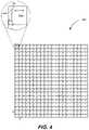
- FIG. 4is a schematic illustration of a field-of-view being imaged by an MFOR-PAMER system, according to certain aspects.
- FIG. 5is a schematic drawing of a plan view and a cross-sectional A-A view of a microlens array, according to one aspect.
- FIG. 6is a flowchart depicting operations of an MFOR-PAMER method, according to certain aspects.
- FIG. 7is a flowchart depicting operations of an MFOR-PAMER method, according to certain aspects.
- FIG. 8 Ais an illustration of the actual positions of simulated microlens focal spots of an MFOR-PAMER system, according to an aspect.
- FIG. 8 Bis a reconstructed image of the simulated microlens array pattern of an MFOR-PAMER system, according to an aspect.
- FIG. 8 Cis a reconstructed image, according to an aspect.
- FIG. 8 Dis an illustration of separation distance for two spots in an MFOR-PAMER system, according to certain implementations.
- FIG. 9 Ais an illustration of the quantification of the acoustical lateral resolution of an imaging system without localization.
- FIG. 9 Bis a graph of the contrast-to-noise ratio versus the distance between the two light spots.
- FIG. 9 Cis an illustration of the quantification of the optical lateral resolution of an MFOR-PAMER system, according to one implementation.
- FIG. 9 Dis an illustration of the edge-spread function used to calculate the line-spread function of an MFOR-PAMER system, according to one implementation.
- FIG. 10 Ais a single-frame reconstructed image from a single scanning step of the microlens array excitation pattern of an of an MFOR-PAMER system, according to one implementation.
- FIG. 10 Bis an image created by an imaging system without localization.
- FIG. 10 Cis an MFOR-PAMER image that was constructed by localizing the optical foci from the scanning steps, according to an aspect.
- FIG. 11 Ais an AR-PAMER image of the ear vasculature with a zoomed in portion.
- FIG. 11 Bis an MFOR-PAMER image of the ear vasculature with a zoomed in portion, according to an aspect.
- FIG. 12is a graph of line profiles across the two white dashed lines in the boxed regions in the zoomed in views from FIG. 11 A-B .
- an MFOR-PAMER systemincludes a pattern-generating device such as a microlens array that can generate multiple illumination beams from a beam such as a pulsed laser beam.
- the illumination beamsare scanned over a field-of-view of a sample being imaged.
- the focal spot of each illumination beamis scanned to a plurality of scan locations over a corresponding optical foci region of a plurality of optical foci regions in the field-of-view.
- An ergodic relayis acoustically coupled to the sample to receive photoacoustic signals generated at the illuminated optical foci regions based on the photoacoustic effect.
- the ergodic relayreflects the photoacoustic signals internally, which scrambles the photoacoustic signals based on their input locations.
- An ultrasonic transducer deviceacoustically-coupled to the ergodic relay can detect the coded photoacoustic signals. Using the calibrated system responses, the system can determine a plurality of snapshot photoacoustic images for the corresponding plurality of scan locations.
- the systemcan localize the pixel values in the optical foci regions of each snapshot photoacoustic image, e.g., by assigning the pixel values within each focal spot to a maximum or mean value of the pixels in that focal spot and zeroing out the pixel values around the focal spot in that optical foci region.
- the systemcombines the plurality of localized snapshot photoacoustic images to generate an MFOR-PAMER image.
- OR-PAMOptical-resolution photoacoustic microscopy
- OR-PAM systemshave found broad application in biomedical imaging technologies based on their ability to image rich optical absorption contrast in biological tissues. Examples of OR-PAM systems are described Wang, L. V & Yao, J., “A practical guide to photoacoustic tomography in the life sciences,” Nat. Methods 13, 627-638 (2016) and Wang, L. V., “Multiscale photoacoustic microscopy and computed tomography,” Nat. Photon. 3, 503-509 (2009), which are hereby incorporated by reference in their entireties.
- OR-PAM systemstypically rely on either mechanical scanning of a single beam with its confocally-aligned ultrasonic transducer for sensitive acoustic detection or mechanically scanning of the object to form an image, limiting the wide-field imaging speed of these systems.
- Some examples of such systemsare described in Yao, J., Wang, L., Yang, J Maslov, K. I., Wong, T. T. W., Li, L., Huang, C., Zou, J., and Wang, L. V., “High-speed label-free functional photoacoustic microscopy of mouse brain in action,” Nat. Methods 12, 407-410 (2015) and Wong, T. T.
- MFOR-PAmultifocal optical-resolution photoacoustic
- MFOR-PACTmultifocal optical-resolution photoacoustic computed tomography
- MFOR-PACT systemsare complex and costly due to their implementation of an ultrasonic transducer array and the associated multi-channel data acquisition system.
- an ultrasonic transducer array with 512 sensing elementsis used.
- the sensing elementsrequire their own amplifiers and data acquisition channels (i.e., 512 amplifiers and channels), making it not easy to implement.
- the applications of the MFOR-PA systemsare limited due to the space needed.
- MFOR-PAMERmultifocal optical-resolution photoacoustic microscopy through an ergodic relay
- the MFOR-PAMER systemsinclude a microlens array or other pattern-generating device that can generate optical excitation at multiple focal spots in a field-of-view of a sample being imaged and an acoustic ergodic relay that can simultaneously detect the photoacoustic responses to the multifocal optical illuminations with an ultrasonic transducer device such as a single-element ultrasonic transducer.
- the MFOR-PAMER systemincludes an ergodic relay (also sometimes referred to herein as an “acoustic ergodic relay” or an “acoustic ergodic cavity”).
- the ergodic relayis a low-loss acoustic propagation medium that scrambles input acoustic waves inside the medium by internally reflecting the waves at boundaries which results in distinct time delay characteristics at an output location for each input location. The waves are reflected at the boundaries due to the discontinuity in acoustic transmissivity between the medium of the ergodic relay and the air or other medium outside the boundaries.
- MFOR-PAMER techniquescan use calibrated time delay characteristics of the ergodic relay and/or the sample and to detect acoustic waves generated at multifocal optically illuminated regions (also sometimes referred to herein as “optical foci regions”) in the field-of-view in parallel using an ultrasound transducer device acoustically coupled to the ergodic relay.
- the ergodic relaycan also project one or more illumination beams to the optical foci regions to generate optical excitation.
- an MFOR-PAMER systemmay include an ergodic relay that projects one or more input illumination beams generated by a pattern-generating device to corresponding optical foci regions in a field-of-view at a sample plane of a sample being imaged and receive at different input locations the acoustic waves generated by the photoacoustic effect at the illuminated optical foci regions.
- An example of an ergodic relayis a light-transparent prism (e.g., prism made of fused silica) such as a right-angle prism.
- a schematically-illustrated example of an ergodic relay in the form of right-angle prismis the ergodic relay 340 shown in FIG. 3 .
- suitable commercially-available ergodic relaysare ultraviolet fused silica right-angle prisms (e.g., PS611, PS612, PS608, PS613, etc.) sold by Thorlabs, Inc. of Newton, N.J.
- the PS611 right-angle prismmade by Thorlabs, Inc. of Newton, N.J.
- MFOR-PAMER systemswith ergodic relays in the form of right-angle prisms or other prisms
- these systemscan implement other types of ergodic relays according to other implementations.
- suitable ergodic relaysinclude glass/quartz plates (e.g., slides, coverslips), silicon wafers, etc.
- an ergodic relaycan be used as an encoder to transform photoacoustic signals from acoustic waves at different input positions into unique temporal signals.
- Examples of systems that use ergodic relaysare described in Cox, B., Beard, P., “Photoacoustic tomography with a single detector in a reverberant cavity” J. Acoust. Soc. Am. 125, 1426 (2009) and Li, Y., Li, L., Zhu, L., Maslov, K., Shi, J., Yao, J., Liang, J., Wang, L., and Wang L.
- the time delay characteristics of the ergodic delaycan be established and the photoacoustic signals from a plurality of illuminated optical foci regions in the field-of-view can be detected by the ultrasound transducer device in parallel based on a single input beam such as a single pulsed laser shot.
- a pattern generating devicecan separate a single input beam into multiple illumination beams directed to illuminate a plurality of optical foci regions at a sample plane in the field-of-view.
- the encoded photoacoustic signalscan then be decoded mathematically to reconstruct a two-dimensional photoacoustic image of the object.
- an MFOR-PAMER systemincludes an ergodic relay that is acoustically coupled at one or more output locations to an ultrasound transducer device to detect encoded photoacoustic signals based on the time delay characteristics of the ergodic relay and/or the sample.
- the ergodic relayreceives a plurality of encoded photoacoustic signals from a plurality of illuminated optical foci regions in the field-of-view of the sample being imaged and delivers a photoacoustic signal for each illumination beam after multiple characteristic time delays relative to the delivery of the illumination beam at the input location to the ergodic relay which corresponds to the location at the sample plane illuminated by the illumination beam.
- the ergodic relayencodes the spatial location of the source of the photoacoustic signal as a characteristic delay between the time of delivery of the illumination beam and the time at which the photoacoustic signal is received from the ergodic relay by the ultrasound transducer device.
- suitable ultrasound transducer devicesinclude a single-element transducer (e.g., a pin-shaped ultrasound transducer), one or more linear transducer arrays, one or more two-dimensional transducer arrays, or any combination thereof.
- a suitable single-element transduceris a pin-shaped ultrasound transducer such as, e.g., the commercially-available VP-0.5 transducer made by CTS Electronics, Inc., which has a 10 MHz central frequency and 0.5 mm element size or the commercially-available VP-0.5-20 MHz transducer made by CTS Electronics, Inc., which has a 20 MHz central frequency, 56% one-way bandwidth, and 0.5 mm element size.
- the ultrasound transducer deviceis asymmetrically acoustically coupled (i.e.
- a single-element ultrasound transducermay be coupled to an ergodic relay at a corner to maximize the distinctions among the received signals from the different input locations.
- the ergodic relaymay be acoustically coupled directly to the ergodic relay or via acoustic coupling material (e.g., polyester resin) to the ergodic relay.
- an MFOR-PAMER systemalso includes a pattern-generating device capable of generating a plurality of N illumination beams with N focal spots in an optical foci pattern (also sometimes referred to herein simply as a “pattern”) where the illumination beams are capable of optical excitation at the focal spots that will generate acoustic waves by the photoacoustic effect in the sample being imaged.
- a pattern-generating devicecapable of generating a plurality of N illumination beams with N focal spots in an optical foci pattern (also sometimes referred to herein simply as a “pattern”) where the illumination beams are capable of optical excitation at the focal spots that will generate acoustic waves by the photoacoustic effect in the sample being imaged.
- suitable patternsinclude a rectangular array, a linear array, a circular array, etc.
- the illumination beamsare propagated from the pattern-generating device to the ergodic relay and the ergodic relay projects the illumination beams to form the optical foci pattern in a field-of-view of the sample
- the illumination beamsare propagated directly from the pattern-generating device to the field-of-view.
- the pattern-generating devicemay be located above a sample located on a surface of the ergodic relay or above the surface with an acoustic gel between the surface and the sample.
- the illumination beamsare propagated via one or more optical elements from the pattern-generating device to the field-of-view.
- FIG. 4An example of a rectangular grid pattern of four-hundred (400) focal spots 412 a from illumination beams propagated, directly or via other optical elements, from a pattern-generating device in the form of a 20 ⁇ 20 microlens array to a sample plane to illuminate a corresponding four-hundred (400) regions 401 a in a field-of-view 400 is shown in FIG. 4 .
- the ultrasonic transducer device coupled to the ergodic delaydetects the encoded photoacoustic signals and the data from these signals can be mapped using the system responses from the calibration data to the known locations of the focal spots in the pattern.
- the encoded photoacoustic signalsare decoded using the system responses (or impulse responses) from the calibration data.
- the reconstructed photoacoustic amplitude imagecan be calibrated by the RMS amplitude of the system responses from the calibration data.
- the pattern-generating deviceis an arrangement of optical elements capable of generating a plurality of illumination beams from a single beam that is propagated directly or via one or more optical elements from a light source.
- suitable pattern-generating devicesinclude a microlens array, a digital mirror, optical fibers, a spatial light modulator such as a liquid-crystal spatial light modulator, and any combination thereof.
- the microlens arrayis arranged to separate a single beam into multiple illumination beams and/or focus the illumination beams to corresponding focal spots.
- the illumination beamsare projected directly from the microlens array to the sample plane, and in other cases via one or more optical elements (e.g., a relay lens).
- the number of illumination beams produced by the microlens arraycorresponds to the number of microlenses in the array.
- a microlens arrayhas at least 100 microlenses. In another aspect, a microlens array has at least 200 microlenses.
- suitable pitch between adjacent microlenses in the arrayinclude 75 ⁇ m, 100 ⁇ m, 200 ⁇ m, 300 ⁇ m, 400 ⁇ m, and 500 ⁇ m.
- the pitch of the microlens arrayis greater than 220 ⁇ m. In another aspect, the pitch of the microlens array is greater than 75 ⁇ m.
- the pitch of a microlens array or other pattern-generating deviceis determined for a particular implementation based on a tradeoff between a desired acoustic resolution and a desired imaging speed.
- the pitch valueshave to be larger than the acoustic resolution. For example, if an MFOR-PAMER system has an acoustic resolution of 220 ⁇ m, the pitch must be greater than 220 ⁇ m.
- the imaging speed of an MFOR-PAMER systemcan be increased by reducing the pitch so that the area of the optical foci region of the field-of-view scanned by a single illumination beam is smaller.
- the microlens arrayis a rectangular array, a circular or curved array, a linear array, or combination thereof.
- the microlens arrayis a 20 ⁇ 20 rectangular array with four hundred (400) microlenses.
- the microlens arrayis a 10 ⁇ 10 rectangular array with one hundred (100) microlenses.
- the microlens arrayis a rectangular array with each dimension being at least 10 microlenses.
- the microlens arrayis a rectangular array with each dimension being at least 20 microlenses.
- a microlens arrayhas at least 100 microlenses.
- a microlens arrayhas at least 200 microlenses.
- microlens arrayAn example of a commercially-available microlens array is the 64-479 microlens array made by Edmund Optic of Barrington, N.J., which is a rectangular microlens array having dimensions 20 ⁇ 20, a 500 ⁇ m pitch between microlenses, and 1.2 degree divergence angle. An example of a microlens array is illustrated in FIG. 5 .
- the digital mirror deviceis capable of generating multiple illumination beams from a single beam and/or focusing the generated illumination beams to a corresponding plurality of focal spots.
- a digital micromirror devicecan be individually rotated to an angle, ⁇ . In this way, each micromirror can be transitioned to either an aperture setting at angle, ⁇ , or to a field setting at no rotation, or vice versa.
- An example of a suitable commercially-available digital micromirror deviceis the DLP9000/DLP9000X DLP® Digital Mirror Device by Texas Instruments®.
- micromirrorsare usually arranged in a rectangular array, other arrangements can be used.
- the pitch value of a digital mirror devicecan be controlled digitally, for example, more or fewer mirror units can be turned on to adjust the pitch value.
- the size of each micromirroris related to the highest acoustic resolution that can be achieved by the digital micromirror device.
- a relay lenscan be used to adjust (improve or degrade) the acoustic resolution.
- the spatial light modulatoris capable of separating a single beam into multiple illumination beams.
- a spatial light modulatoruses an electrical and/or optical signal from a spatial light modulator light source to modulate phase, ⁇ , and/or amplitude of light.
- the spatial light modulator light sourceis a collimated light source such as a laser (e.g., Excelsior® 532 SM).
- the spatial light modulator light sourcemay be spatially filtered light from a light emitting diode.
- the pitch value of a spatial light modulatorcan be adjusted by turning on or off more or fewer elements.
- An example of a commercially-available spatial light modulatoris the reflective HOLOEYE® spatial light modulator sold by Pluto, which is a phase only LCoS with 8 ⁇ m pixel size and a 1080 ⁇ 1920 pixels display.
- an MFOR-PAMER systemcombines the powerful capability of an ergodic relay with a single-element ultrasonic transducer to detect multiple photoacoustic signals in parallel with a simple system setup. In these cases, the MFOR-PAMER system is a low-cost alternative to systems that implement a transducer array. Additionally or alternatively, an MFOR-PAMER system may implement a microlens array or other pattern-generating device to shape a wide-field laser beam into multiple optical focal spots to reduce the scanning time. Since the excitation pattern through the microlens array or other pattern-generating device is known, the response from each optical focal spot can be computationally localized to improve the acoustically defined image resolution.
- an MFOR-PAMER systemincludes a pattern-generating device in the form of a two-dimensional microlens array having 20 ⁇ 20 microlens elements having a 500 ⁇ m pitch between the elements.
- the microlens arrayreceives a single pulsed laser beam and can generate four hundred (400) illumination beams that are projected through the ergodic relay to generate four hundred (400) optical foci in the field-of-view at a sample plane of the object.
- the MFOR-PAMER systemalso includes a single element transducer element coupled to a corner of the ergodic relay that can detect photoacoustic signals from the illuminated four-hundred (400) optical foci regions in the field-of-view in a single laser shot.
- This MFOR-PAMER systemimproves the imaging resolution from 220 ⁇ m to 13 ⁇ m, which is a factor of ⁇ 17, as compared to OR-PAM systems.
- this MFOR-PAMER systemachieves a 400 times improvement in imaging speed over a 10 mm ⁇ 10 mm field-of-view as compared to OR-PAM systems at the same resolution and laser repetition rate.
- microlens arrayscan be found in Prevedal, R., Yoon, Y., Hoffmann, M., Pak, N., Wetzstein, G., Kato, S., Schrodel, T., Raskar, R., Zimmer, M., Boyden, E. S., and Vaziri, A., “Simultaneous whole-animal 3D imaging of neuronal activity using light-field microscopy,” Nat. Methods 11, 727-730 (2014) and Fujitaa, K., Nakamuraa, O., Kanekoa, T., Oyamadab, M., Takamatsub, T., and Kawataa, S. “Confocal multipoint multiphoton excitation microscope with microlens and pinhole arrays,” Opt. Comm. 174, 7-12 (2000), which are hereby incorporated by reference in their entireties.
- Certain implementations of the MFOR-PAMER systems and methodshave one or more technical advantages.
- certain implementations of an MFOR-PAMER systeminclude a pattern-generating device that enable a simple and compact design that allows the system to be more flexible and portable which is compatible with various applications.
- one implementation of an MFOR-PAMER systemimproves the imaging resolution from 220 ⁇ m to 13 ⁇ m as compared to OR-PAM systems that do not have a pattern-generating device.
- one implementation of an MFOR-PAMER systemmay improve the imaging speed over a 10 mm ⁇ 10 mm field-of-view by 400 times as compared to an OR-PAM system at the same resolution and laser repetition rate.
- the MFOR-PAMER systems and methodshave promising potential use in many biomedical applications, such as utilizing ultra-violet illumination for high-speed, label-free histological study of biological tissues.
- using MFOR-PAMER systems and methodscan reduce the imaging time from several hours to less than a minute (as compared to ultra-violet optical resolution photoacoustic microscopy (OR-PAM) systems), which, if implemented, may significantly improve the efficiency of clinical histology and diagnostics.
- OR-PAMultra-violet optical resolution photoacoustic microscopy
- an MFOR-PAMER systemincludes one or more light sources that can provide pulsed or modulated radiation with properties that can generate temporal data and cause optical excitation resulting in the photoacoustic effect in the sample being imaged.
- suitable pulsed light sourcesinclude: pulsed (1) laser, (2) flash lamp, (3) laser diode, (4) light emitting diode, etc.
- suitable modulated light sourcesinclude modulated (i) continuous-wave laser, (ii) flash lamp, (iii) laser diode, (4) light-emitting diode, etc.
- a light source in the form of a pulsed laser or other pulsed light sourcethat can deliver a series of light pulses suitable for photoacoustic imaging.
- the light pulse wavelength, duration, and pulse repetition rate (pulses/sec)are selected based on one or more factors such as, e.g., selective absorbance of pulse wavelength by structures or objects of interest in the sample being imaged, scattering of the pulse wavelength through the sample being imaged, sufficient pulse duration to produce detectable photo acoustic signals, etc.
- the light pulsesare in a range of wavelengths between 200 nm and 6500 nm. In one aspect, the wavelength of the light pulses is about 266 nm. In another aspect, the wavelength of the light pulses is about 532 nm.
- the wavelength of the light pulsesis about 559 nm. In another aspect, the wavelength of the light pulses is about 650 nm. In another aspect, the wavelength of the light pulses is about 680 nm. In another aspect, the wavelength of the light pulses is about 930 nm. In another aspect, the wavelength of the light pulses is about 1064 nm. In another aspect, the wavelength of the light pulses is about 1210 nm. In another aspect, the wavelength of the light pulses is about 1710 nm.
- suitable ranges of wavelengthsinclude: ranges between 200 nm and 6500 nm, in particular (some examples) 266 nm, 532 nm, 559 nm, 650 nm, 680 nm, 930 nm, 1064 nm, 1210 nm, 1710 nm.
- the light pulseshave a pulse width less than 10 ns. In one aspect, the light pulses have a pulse width of 3 ns. In one aspect, the light pulses have a pulse width of 100 ps. In one aspect, the light pulses have a pulse width of 20 ps. In one aspect, the light pulses have a pulse width of 200 fs.
- a pulsed light sourceprovides light pulses at a repetition rate in the range between about 10 Hz and about 10 kHz. In one aspect, the pulsed light source provides light pulses at a repetition rate at or above 2 kHz. In another aspect, the pulsed light source provides light pulses at a repetition rate at or above 10 kHz. In another aspect, the pulsed light source provides light pulses at a repetition rate at or above 10 Hz. In another aspect, the pulsed light source provides light pulses at a repetition rate at or above 100 Hz. In another aspect, the pulsed light source provides light pulses at a repetition rate at or above 1 kHz.
- a suitable light sourceis a pulsed laser configured to deliver a series of laser pulses at a pulse wavelength of 532 nm.
- An example of a suitable commercially-available pulsed laseris the INNOSAB IS811-E sold by Edgewave® GmbH with a 2 KHz pulse repetition rate and 5-ns pulse width.
- a pattern-generating devicegenerates a plurality of illumination beams from a single light beam propagated directly, or via one or more optical elements, from a light source (e.g., a pulsed laser, a light-emitting diode, etc.).
- a light sourcee.g., a pulsed laser, a light-emitting diode, etc.
- the one or more optical elementsmay, in some cases, modify the light beam delivered to the pattern-generating device, e.g., by adjusting the amount or properties of the light energy delivered.
- suitable optical elementsinclude optical fibers, lenses, mirrors, beam splitters, optical filters, etc.
- one of the optical elementsmay be an aperture (e.g., pinhole) that can be contracted or dilated to spatially filter the light beam.
- two of the optical elementsmay be a pair of lenses that act together to expand the light beam.
- one or more of the optical elementsmay be a mirror or a beam splitter that reflects the beam or a portion of the light beam in another direction.
- one or more of the optical elementsmay be a lens, e.g., a focusing lens to focus the light beam to narrow the lateral dimensions of the beam or two lenses to widen the lateral dimensions of the beam.
- FIG. 2An illustrated example of one or more optical elements 212 a , 212 b , 212 c , 212 d , 212 e , 212 f , 212 g , and 212 h between the pattern-generating device 214 in the form of a microlens array and the light source 210 in the form of a pulse laser are shown in FIG. 2 .
- a pinhole mechanism 212 bis used to spatially filter a pulsed laser beam and the pair of lenses 212 e , 212 f to expand the lateral dimensions of the pulsed laser beam.
- the MFOR-PAMER systemincludes a beam sampler to monitor the energy of the light pulses from the pulsed laser. The energy of each light pulse is measured and the measurements are used to apply corrections to the measured photoacoustic signals.
- an MFOR-PAMER systemincludes a scanning mechanism capable of scanning one or more elements of the MFOR-PAMER system to cause the plurality of illumination beams generated by the pattern-generating device to be scanned.
- Each of the illumination beamsis scanned so that the its focal spot is moved to a plurality of locations in an optical foci region of the field-of-view being imaged.
- the scanning mechanismscans the focal spots of the illumination beams in one direction in the sample plane such as in a direction along a local x-axis in the corresponding optical foci regions.
- the scanning mechanismscans the focal spots in two directions in the sample plane, e.g., a first direction along the local x-axis and a second direction along a local y-axis in the corresponding optical foci regions.
- each of the focal spotsis scanned to a plurality of locations in the sample plane over the corresponding optical region of the field-of-view.
- the ultrasonic transducer device coupled to the ergodic relaysimultaneously detects encoded photoacoustic signals.
- the data from the encoded photoacoustic signalscan be mapped to pixel locations in the field-of-view using the system responses from the calibration data.
- suitable scanning mechanismsare an x-y stage, a galvanometric mirror (non-resonant/resonant), an acousto-optic device, one or more motorized scanning stages, a spinning polygon mirror, etc.
- the scanning mechanismincludes two motorized translation stages.
- An example of a commercially-available motorized translation stageis a PLS-85 stage made by PI Inc.® with US headquarters located in Auburn, Mass.
- an MFOR-PAMER systemincludes a digitizer such as, e.g., a two-channel digitizer, that can record data from the photoacoustic signals received from an ultrasonic transducer device.
- the digitizermay also record measurements taken by other system components.
- a commercially-available two-channel digitizeris the ATS9350 two-channel digitizer made by Alazar Tech Inc.® with a 50 MS/s sampling rate and 16384 samples/A-line sample length.
- the digitizermay also function to convert the electrical signals into digital data.
- an MFOR-PAMER systemincludes one or more processor(s) and a computer readable medium CRM.
- the processor(s)execute instructions stored on the CRM to perform one or more operations of the MFOR-PAMER system.
- the processor(s) of the MFOR-PAMER system and/or one or more external processorsmay execute instructions that construct a photoacoustic image of the field-of-view of the sample from the data in the photoacoustic signals received from the ultrasonic transducer device.
- processor(s) of the MFOR-PAMER system and/or one or more external processorsmay execute instructions that cause the communication of control signals to control operations of one or more system components (e.g., control light pulses delivered by the light source, control the scanning movement from a scanning mechanism, etc.).
- processorse.g., a general purpose processor (CPU), an application-specific integrated circuit, a programmable logic device (PLD) such as a field-programmable gate array (FPGA), and a System-on-Chip (SoC).
- CPUgeneral purpose processor
- PLDprogrammable logic device
- FPGAfield-programmable gate array
- SoCSystem-on-Chip
- the CRMincludes a non-volatile memory array for storing processor-executable code (or “instructions”) that is retrieved by the processor(s) to perform various functions or operations described herein for carrying out various logic or other operations on the photoacoustic signals or image data.
- the CRMcan also store raw data and/or processed image data.
- the CRM or a separate memorycan additionally or alternatively include a volatile memory for temporarily storing code to be executed as well as image data to be processed, stored, or displayed.
- the MFOR-PAMER systemincludes one or more communication interfaces (e.g., a universal serial bus (USB) interface).
- Communication interfacescan be used, for example, to connect various peripherals and input/output (I/O) devices such as a wired keyboard or mouse or to connect a dongle for use in wirelessly connecting various wireless-enabled peripherals.
- I/Oinput/output
- Such additional interfacesalso can include serial interfaces such as, for example, an interface to connect to a ribbon cable.
- serial interfacessuch as, for example, an interface to connect to a ribbon cable.
- the various system componentscan be electrically coupled to communicate with various components over one or more of a variety of suitable interfaces and cables such as, for example, USB interfaces and cables, ribbon cables, Ethernet cables, among other suitable interfaces and cables.
- FIG. 1is a schematic illustration of an MFOR-PAMER system 100 , according to various implementations.
- the MFOR-PAMER system 100includes a light source 110 (e.g., a pulsed laser or a light emitting diode) that can produce a light beam 111 of pulsed or modulated radiation.
- the MFOR-PAMER system 100also includes an optical system 120 with a pattern-generating device 122 (e.g., a microlens array, a digital mirror, or a spatial light modulator) in optical communication with the light source 110 to receive the light beam 111 .
- a pattern-generating device 122e.g., a microlens array, a digital mirror, or a spatial light modulator
- the optical system 120further includes one or more optical elements, e.g., one or more mirrors, that direct the light beam 111 from the light source 110 to the pattern-generating device 122 and/or modify the light beam 111 , e.g., an aperture that can spatially filter the light beam 111 and/or an two or more lenses that can expand the light beam 111 .
- the pattern-generating device 122receives the beam directly from the light source 110 .
- the pattern-generating device 122is configured or configurable to generate a plurality of illumination beams 123 from the light beam 111 (unmodified or unmodified by intervening optical elements) from the light source 110 .
- the pattern-generating device 122is illustrated as generating twelve (12) illumination beams. It would be understood that the pattern-generating device 122 can generate greater numbers of illumination beams and in any suitable pattern.
- the pattern-generating device 122may in certain implementations generate greater than one hundred (100) beams, greater than two hundred (200) beams, greater than three hundred (300) beams etc.
- the pattern-generating device 122is a 20 ⁇ 20 microlens array that generates two hundred (200) beams in a rectangular grid pattern.
- the MFOR-PAMER system 100also includes an ergodic relay 140 in acoustic communication with the sample 10 to receive acoustic waves from regions in a field-of-view of the sample 10 illuminated by the illumination beams 123 .
- the ergodic relay 140is either touching or coupled via a coupling material (e.g., acoustic gel) to a surface of the sample 10 being imaged during an imaging process.
- the MFOR-PAMER system 100also includes an ultrasonic transducer device 150 coupled to or otherwise in acoustic communication with the ergodic relay 140 at output locations(s) to detect photoacoustic signals from the illuminated regions of the sample 10 .
- the ergodic relay 140is also in optical communication with the pattern-generating device 122 to receive the plurality of illumination beams 123 from the pattern-generating device 122 and project the illumination beams 123 such that a pattern of focal spots 124 of the illumination beams 111 is projected to a sample plane 11 of a sample 10 being imaged.
- the pattern-generating device 122is located so that its focusing plane is imaged onto the imaging face of the ergodic relay 140 to illuminate the sample plane 11 of the sample 10 .
- one or more other optical elementsare implemented to propagate the plurality of illumination beams 123 to the sample 10 . In these cases, the ergodic relay 140 need not be in optical communication with the pattern-generating device 122 .
- one or more optical elementsare in the optical path between the pattern-generating device 122 and the ergodic relay 140 .
- a relay lensmay be in optical communication with the pattern-generating device 122 to receive the plurality of illumination beams 123 and extend their focal length to the sample plane 11 .
- the illustrated ergodic relay 140is in the form of a right-angle prism such as, e.g., the commercially-available right-angle prism PS611 sold by Thorlabs, Inc. of Newton, N.J. with 2,203 kg/m 3 density and 73.6 GPa Young's modulus.
- ergodic relayscan be used such as glass/quartz plates (e.g., slides, coverslips), silicon wafers, etc.
- the illustrated examplealso includes an x-axis and a y-axis (not shown) in the sample plane 11 , and a z-axis.
- the y-axisis orthogonal to the x-z plane.
- the ergodic relay 140is in acoustic communication with the sample 10 to receive acoustic waves from the illuminated regions of the sample 10 illuminated by the pattern of focal spots 124 of the illumination beams 123 .
- the ergodic relay 140is a low-loss acoustic propagation medium that scrambles input acoustic waves from the sample 10 and encodes the photoacoustic signals detected by the ultrasonic transducer device 150 with distinct time delay characteristics for each input location of acoustic waves from an illuminated region of the sample 10 .
- the ultrasonic transducer device 150e.g., a single element transducer, is in acoustic communication with the ergodic relay 150 to detect the encoded photoacoustic signals with the distinct time delay characteristics for each input location.
- the ultrasonic transducer deviceis in acoustic communication with, e.g., coupled directly or acoustically connected via an acoustic material (e.g., an acoustic gel) to, the ergodic relay at a location or multiple locations that creates an asymmetric relationship between the ultrasonic transducer device and ergodic relay.
- an acoustic materiale.g., an acoustic gel
- the illustrated ergodic relay 150is schematically depicted as coupled to a face of the ergodic relay 140 at the corner to provide such an asymmetric relationship between the ergodic relay 150 and the ultrasonic transducer device 150 to increase the distinctions among the photoacoustic signals from acoustic waves received at different input locations along the surface of the ergodic relay 150 coupled to the sample 10 .
- the ultrasonic transducer device 150is shown coupled directly to the ergodic relay 140 , it would be understood that there may be an acoustic material (e.g., an acoustic gel, a needle, etc.) located between the ultrasonic transducer device 150 and the ergodic relay 140 .
- the MFOR-PAMER system 100also includes a scanning mechanism 130 coupled to one or more elements of the optical system 120 .
- the scanning mechanism 130is coupled to the light source 110 , in addition to or in the alternative to, the one or more elements of the optical system 120 .
- the scanning mechanism 130is coupled to one or more components of the MFOR-PAMER system 100 to be able to move the focal spots 124 of the illumination beams 123 to different locations at the sample plane 11 .
- Each of the illumination beams 123is scanned to locate its focal spot 124 at a plurality of locations in a corresponding optical foci region in the field-of-view being imaged.
- the scanning mechanism 130moves the focal spot 124 in a first direction along the x-axis and/or in a second direction along the y-axis at the sample plane.
- the scanning mechanism 130includes one or more mechanical motors to move the one or more system components.
- the scanning mechanism 130includes a first motor or other mechanism to move one or more components in a first direction and a second motor or other mechanism to move one or more components in a second direction.
- suitable scanning mechanismsinclude an x-y stage, a galvanometric mirror (non-resonant/resonant), an acousto-optic device, one or more motorized scanning stages, a spinning polygon mirror, etc.
- the MFOR-PAMER system 100also includes a digitizer 180 (e.g., a two-channel digitizer) in electrical communication with the ultrasonic transducer device 150 to receive and record photoacoustic signals.
- the MFOR-PAMER system 100also includes one or more processors 160 and a computer readable medium (CRM) 170 in electronic communication with the processor(s) 160 .
- the processor 160is also in electronic communication with the scanning mechanism 130 , the light source 110 , and the digitizer 180 to be able to send control signals.
- the digitizer 180is in electronic communication with the CRM 170 to store the recorded photoacoustic signal data.
- the processor(s) 160executes instructions stored on the CRM 170 to perform one or more operations of the MFOR-PAMER system 100 .
- the processor(s) 160 and/or one or more external processorsexecute instructions that construct a photoacoustic image of the field-of-view of the sample 10 from the data in the photoacoustic signals received from the ultrasonic transducer device 150 and/or execute instructions that communicate control signals to system components.
- the processor(s) 160 and/or one or more external processorsmay execute instructions that communicate control signals to the scanning mechanism 130 to scan focal spots 124 of the illumination beams 123 to different locations in the regions of the field-of-view and communicate control signals to the digitizer 180 to simultaneously record photoacoustic signals relayed through the ergodic relay 140 from the illuminated regions of the sample 10 for each of the locations in the regions.
- the processor(s) 160 and/or one or more external processorsmay execute instructions that communicate control signals to the light source 110 to control the light pulses or other modulated light delivered by the light source 110 .
- the described electrical communications between components of the MFOR-PAMER system 100are able to provide power and/or communicate signals with data.
- the MFOR-PAMER system 100also includes an optional (denoted by dotted lines) first communication interface 191 , one or more optional input devices 190 in communication with the processor(s) 160 through the first communication interface 191 , a second communication interface 192 , and a display 192 in communication with the processor(s) 160 through the second communication interface 193 .
- the optional input device(s) 190are in communication with the processor(s) 160 through the first communication interface 191 to be able to send a signal with imaging operational parameters or display parameters based on input received at the input device(s) 190 .
- the processor(s) 160is configured or configurable to communicate data over the second communication interface 193 for display on the display 192 including, e.g., raw data from the photoacoustic signals and a constructed photoacoustic image.
- the second communication interface 192is in communication with the input device(s) 190 to receive input, e.g., from an operator.
- sample 10is illustrated as a block, it would be understood that the sample 10 can be in a variety of shapes and may have one or more objects of interest.
- the processor(s) 160executes instructions that send control signals to the light source 110 to deliver a beam of pulsed or modulated radiation which are converted into a plurality of illumination beams 123 , control signals to the scanning mechanism 130 to scan the illumination beams 123 , control signals to the digitizer 180 to record photoacoustic signals received from the ultrasonic transducer device 150 .
- the digitizer 180records photoacoustic signals for each of the locations of the focal spots of the illumination beams 123 in regions of the field-of-view of the sample 10 being imaged.
- the processor(s) 160executes instructions to perform operations to construct a photoacoustic image from the data in the photoacoustic signals.
- the calibrated system responsesare used to map the amplitudes of the recorded photoacoustic signals to: i) pixels within the areas of the focal spots in the optical foci regions of the field-of-view, or ii) the pixels within the field-of-view. This first operation is done for each illumination pattern (i.e., for each scanning location of the illumination beams).
- a localization operationis performed for the pixels in each optical foci region that: i) determines a maximum or mean amplitude value of the pixel values within the area of each focal spot, and ii) assigns the pixels within the area of the focal spot to the determined maximum or mean amplitude value and zeroes out the pixel values around the focal spot.
- the localization operationis performed for each illumination pattern to generate a plurality of localized images.
- the pixel values from the plurality of localized imagesare summed to generate a photoacoustic image of the field-of-view of the sample 10 .
- FIG. 2is a schematic illustration of an MFOR-PAMER system 200 , according to various implementations.
- the MFOR-PAMER system 200includes a light source 210 in the form of a pulsed laser that can produce laser pulses for optical excitation in a sample 20 being imaged.
- a light source 210in the form of a pulsed laser that can produce laser pulses for optical excitation in a sample 20 being imaged.
- An example of a suitable commercially-available pulsed laseris the INNOSAB IS811-E sold by Edgewave® GmbH with a 2 KHz pulse repetition rate and 5-ns pulse width.
- the illustrated examplealso includes an x-axis, a y-axis, and a z-axis. The x-axis and y-axis are in the sample plane.
- the MFOR-PAMER system 200also includes an optical system with a first lens 212 a configured to focus the beam from the light source 210 and an aperture (e.g., pinhole) 212 b configured to spatially filter the beam from the first lens 212 a .
- a suitable commercially-available first lens 212 a that can focus the beam to a 5 ⁇ m laser spotis the LA1509 lens made by Thorlabs, Inc.® with a 25.4 mm diameter and 100 mm focal length.
- the optical systemalso includes a second lens 212 c configured to collimate the beam spatially-filtered by the aperture 212 b , a first mirror 212 d configured to reflect the beam collimated by the second lens 212 c , a third lens 212 e configured to propagate the beam reflected from the first mirror 212 d , a fourth lens 212 f configured to collimate the beam, a second mirror 212 g configured to reflect the beam from the fourth lens 212 f , and a third mirror 212 h configured to reflect the beam from the second mirror 212 g .
- the third lens 212 e and the fourth lens 212 fact together to laterally expand the beam.
- the optical systemalso includes a pattern-generating device 222 (e.g., a microlens array, a digital mirror, or a spatial light modulator) located to receive the pulsed beam reflected by the third mirror 212 h and generate a plurality of illumination beams 223 , and a relay lens 216 configured to extend the focal lengths of the plurality of illumination beams 223 .
- a pattern-generating device 222e.g., a microlens array, a digital mirror, or a spatial light modulator
- a relay lens 216configured to extend the focal lengths of the plurality of illumination beams 223 .
- the lenses and mirrors of an MFOR-PAMER systemare selected based on the illumination wavelength. For the MFOR-PAMER system 200 , the focal lengths of a lens pair controls how much the light beam will be expanded.
- lens 212 fhas a focal length of 100 mm
- lens 212 ehas a focal length of 20 mm
- lenses 212 a and 212 ccan have the same focal length.
- the pattern-generating device 222is configured or configurable to generate a plurality of illumination beams 223 from the adjusted pulsed laser beam reflected by the third mirror 212 h .
- the pattern-generating device 222is illustrated as generating a small number of illumination beams. It would be understood that the pattern-generating device 222 can generate greater numbers of illumination beams and in any suitable pattern.
- the pattern-generating device 222may in certain implementations generate greater than one hundred (100) beams, greater than two hundred (200) beams, greater than three hundred (300) beams etc.
- the pattern-generating device 222is a 20 ⁇ 20 microlens array that generates two hundred (200) beams in a rectangular grid pattern.
- the MFOR-PAMER system 200also includes an ergodic relay 240 .
- the ergodic relay 240is depicted in the illustration in the form of a right-angle prism.
- An example of a suitable commercially-available ergodic relay that can be implementedis the PS611 right-angle prism sold by Thorlabs, Inc. of Newton, N.J. with 2,203 kg/m 3 density and 73.6 GPa Young's modulus.
- Other examples of a right-angle prismsare described in Li, Y., Li, L., Zhu, L., Maslov, K., Shi, J., Yao, J., Liang, J., Wang, L., and Wang L.
- the ergodic relay 240is also in optical communication with the relay lens 216 to receive the plurality of illumination beams 223 and propagate the plurality of illumination beams 123 to the sample 10 .
- one or more other optical elementsare implemented to propagate the plurality of illumination beams 223 to the sample 20 .
- the relay lens 216is in optical communication with the pattern-generating device 222 to receive the plurality of illumination beams 223 from the pattern-generating device 222 and extend their focal length to the sample plane 21 .
- An example of a suitable commercially-available relay lensis the 272EN II camera lens sold by Tamron Inc.® with a 0.29 m minimum focus distance and 1:1 maximum magnification ratio.
- the pattern-generating device 222is located so that its focusing plane is imaged onto the imaging face of the ergodic relay 240 to illuminate the sample plane of the sample 20 with a pattern of focal spots of the illumination beams 223 .
- the relay lens 216is not needed and can be removed where the focal length of the illumination beams 223 from the pattern-generating device 222 is sufficient to allow the focusing plane of the pattern-generating device 222 to be imaged onto the imaging face of the ergodic relay 240 without the relay lens.
- the sample 20 being imagedis touching the surface of the ergodic relay 240 and/or acoustically coupled via a coupling material (e.g., acoustic gel) to the surface of the ergodic relay 240 .
- the MFOR-PAMER system 200also includes an ultrasonic transducer device 250 coupled to or otherwise in acoustic communication with the ergodic relay 240 at a corner to break symmetry.
- An example of a suitable ultrasonic transducer device 250is a miniature single element miniature ultrasonic transducer such as the XMS-10 ultrasonic transducer by Olympus, Inc.® with a 10 MHz central frequency and 0.3 mm element size.
- the ultrasonic transducer device 250is configured to detect photoacoustic signals received at input locations from the illuminated regions of the sample 20 .
- the ergodic relay 240is a low-loss acoustic propagation medium that scrambles input acoustic waves from the sample 20 and encodes the photoacoustic signals detected by the ultrasonic transducer device 250 with distinct time delay characteristics for each input location of acoustic waves from an illuminated region of the sample 20 .
- the ultrasonic transducer device 250e.g., a single element transducer, is in acoustic communication with the ergodic relay 250 to detect the encoded photoacoustic signals with the distinct time delay characteristics for each input location.
- the ultrasonic transducer device 250is shown coupled directly to the ergodic relay 240 , it would be understood that there may be an acoustic material may be located between the ultrasonic transducer device 250 and the ergodic relay 240 .
- the MFOR-PAMER system 200also includes an x-scanning motor 230 a coupled to the third mirror 212 h and the pattern-generating device 222 and a y-scanning motor 230 b coupled to the second mirror 212 g .
- the x-scanning motor 230 ais configured to move the third mirror 212 h and the pattern-generating device 222 to cause the focal spots of the illumination beams 223 to move in the x-direction in the sample plane of the sample 20 .
- the y-scanning motor 230 ais configured to move the second mirror 212 g to cause the focal spots of the illumination beams 223 to move in the y-direction in the sample plane of the sample 20 .
- the x-scanning motor 230 a and y -scanning motor 230 bare configured to scan the illumination beams 223 in the sample plane such that the focal spot of each illumination beam 223 is moved to a plurality of locations in the corresponding optical foci region of the field-of-view being imaged.
- An illustration depicting focal spots of four hundred (400) illumination beams being scanned in a corresponding plurality of optical foci regionsis shown in FIG. 4 .
- the MFOR-PAMER system 200also includes a digitizer 280 (e.g., a two-channel digitizer) in electrical communication with the ultrasonic transducer device 250 to record the encoded photoacoustic signals.
- a digitizer 280e.g., a two-channel digitizer
- An example of a suitable commercially-available digitizeris the ATS9350 two-channel digitizer made by AlazarTech, Inc. that can be adjusted to have up to a 100 MS/s sampling rate.
- the MFOR-PAMER system 200also includes one or more processors 260 and a computer readable medium (CRM) 270 in electronic communication with the processor(s) 260 .
- the processor(s) 260is also in electronic communication with the x-scanning motor 230 a , the y-scanning motor 230 b , the digitizer 280 , and the light source 210 to send control signals.
- the processor(s) 260is in electronic communication with the digitizer 280 to send control signals to activate the digitizer 280 to record the encoded photoacoustic signals.
- the digitizer 280is in electronic communication with the CRM 270 to store the recorded photoacoustic signal data.
- the processor(s) 260executes instructions stored on the CRM 270 to perform one or more operations of the MFOR-PAMER system 200 .
- the processor(s) 260 and/or one or more external processorsexecute instructions that construct a photoacoustic image of the field-of-view of the sample 20 from the data in the photoacoustic signals recorded by the from the ultrasonic transducer device 250 and/or execute instructions that communicate control signals to system components.
- the processor(s) 260 and/or one or more external processorsmay execute instructions that communicate control signals to the x-scanning motor 230 a and the y-scanning motor 230 b to cause the scanning of the focal spots of the illumination beams 223 to different (x,y) locations in the regions of the field-of-view and to communicate control signals to the digitizer 280 to simultaneously record the encoded photoacoustic signals relayed through the ergodic relay 240 from the illuminated regions of the sample 20 for each of the locations in the regions.
- processor(s) 260 and/or one or more external processorsmay execute instructions that communicate control signals to the light source 210 to control the light pulses or other modulated light delivered by the light source 210 .
- the described electrical communications between components of the MFOR-PAMER system 200are able to provide power and/or communicate signals with data.
- electrical communication between components of the various MFOR-PAMER systems described hereincan be in wired or wireless form. It would also be understood that the sample 20 being imaged by the MFOR-PAMER system 100 can be of any variety of shapes and have one or more objects of interest.
- the processor(s) 260executes instructions that send control signals to the light source 210 to generate a pulsed beam which is spatially filtered and expanded and propagates to the pattern-generating device 222 .
- the pattern-generating device 222generates a plurality of plurality of illumination beams 123 from the beam.
- the processor(s) 260also executes instructions processor(s) 260 that send control signals to the x-scanning motor 230 a and y -scanning motor that cause the focal spots of the illumination beams 123 to be scanned over the field-of-view of the sample 20 being imaged.
- the processor(s) 260also executes instructions processor(s) 260 that send control signals to the digitizer 180 to simultaneously record photoacoustic signals received from the ultrasonic transducer device 150 .
- the digitizer 280records photoacoustic signals for each of the locations of the focal spots of the illumination beams 223 in regions of the field-of-view of the sample 20 being imaged.
- the processor(s) 260executes instructions to perform operations to construct a photoacoustic image from the data in the photoacoustic signals.
- the calibrated characteristic time delays of the ergodic relay 240are used to map the RMS amplitudes of system responses to: i) the pixels within the areas of the focal spots in the optical foci regions of the field-of-view, or ii) the pixels within the field-of-view.
- This first operationis done for each illumination pattern (i.e., for each scanning location of the illumination beams).
- a localization operationis performed that: i) determines a maximum or mean amplitude value of the pixel values within the area of each focal spot, and ii) assigns the pixels within the areas of each focal spot to the determined maximum or mean amplitude value and zeroes out the pixel values around the focal spot.
- the localization operationis performed for each illumination pattern to generate a plurality of localized images.
- the pixel values from the plurality of localized imagesare summed to generate a photoacoustic image of the field-of-view of the sample 10 .
- FIG. 3is a schematic illustration of a side view of an ergodic relay 340 in the form of a right-angle prism, according to certain aspects.
- the ergodic relay 340includes a first face 342 , a second face 344 , and a third face 346 .
- the illustrated exampleis shown at an instant in time during a data acquisition phase during which a plurality of illumination beams, including a first illumination beam 323 a with a first focal spot 324 a and a second illumination beam 323 b with a second focal spot 324 b , are simultaneously received at the first face 342 of the ergodic relay 340 .
- the first illumination beam 323 a and the second illumination beam 323 bare propagating through the ergodic relay 340 and the second face 344 reflects the illumination beams 202 a,b toward the third face 346 and enters the sample 30 being imaged.
- a single element ultrasonic transducer device 350is coupled to a location at the corner of the ergodic relay 340 along the second face 344 .
- the focal spots of the plurality of illumination beamsare scanned along a sample plane 31 over a field-of-view 328 of the sample 30 being imaged. Each focal spot is scanned in a corresponding optical focal region of the field-of-view 328 .
- the illumination beams 323 a,bare directed into the sample 30 through the third face 346 and carry sufficient energy to induce localized heating of sample 30 illuminated by the illumination beams 323 a,b , resulting in the production of photoacoustic signals due to the photoacoustic effect.
- the photoacoustic signals in the form of ultrasound waves induced by an illumination beampropagate in all directions away from the illuminated region of the sample 30 including in the direction of the third face 346 of the ergodic relay 340 .
- an acoustic coupling gel 38has been applied to the sample 30 and/or the surface of the third face 346 to enhance the efficiency of transfer of the photoacoustic signals into the third face 346 .
- a photoacoustic signal 326 ais shown entering the ergodic relay 340 through the third face 346 propagating across the material of the ergodic relay 340 and internally reflected due to the discontinuity in the acoustic transmissivity of the material between the ergodic relay 340 and the surrounding air. It would be understood that a plurality of photoacoustic signals are generated at the areas of the sample being illuminated by the plurality of focal spots of the illumination beams and that the plurality of photoacoustic signals are being propagating through the ergodic relay 340 during each scanning step in the data acquisition phase.
- Each photoacoustic signalreflects internally within ergodic relay 340 between the internal surfaces of the first face 342 , second face 344 , and third face 346 .
- the internal path of each photoacoustic signal from a particular location of the region illuminated at the sample plane 31 to the single element ultrasonic transducer device 350will have a distinct time delay characteristics based on the internal reflections.
- the internal path of the photoacoustic signal 326 a within the ergodic relay 340directs the photoacoustic signal 326 a to the single element ultrasonic transducer device 350 coupled to the corner of the ergodic relay 340 .
- the ultrasonic transducer device 350can detect the incoming photoacoustic signal 326 a encoded with a time delay due to its internal path. Since the internal path is associated with a particular location of the illuminated region of the sample 30 , the photoacoustic signal 326 a can be mapped to the location of the sample based on the time delay in the photoacoustic signal 326 a.
- FIG. 4is a schematic illustration of a field-of-view 400 being imaged by an MFOR-PAMER system that includes a pattern-generating device in the form of a 20 ⁇ 20 microlens array, according to certain aspects.
- the illustrated exampleis shown at an instant in time, t i , during a data acquisition phase when the plurality of four-hundred (400) illumination beams are projected to the sample plane and form an optical foci pattern (also sometimes referred to herein as “pattern”) in a rectangular grid pattern of focal spots at a sample plane.
- the field-of-view 400has four-hundred (400) optical foci regions.
- the illumination beamsare scanned so that each focal spot in the pattern is scanned to a plurality of locations in a corresponding optical foci region of the four-hundred (400) optical foci regions of the field-of-view 400 .
- the number of optical foci regions of the field-of-view 400corresponds to the number of illumination beams being scanned.
- An example of a 20 ⁇ 20 microlens array capable of generating a plurality of four-hundred (400) illumination beams with focal spots in a rectangular grid patternis the microlens array 500 shown in FIG. 5 .
- the illustrated exampleshows an enlarged portion of the field-of-view 400 at the upper right corner with an optical foci region 410 a with a focal spot 412 a (also sometimes referred to herein as an “optical foci”) of the corresponding illumination beam at an x, y location 420 a at this instant in time, t i , during the scanning of the illumination beams.
- a focal spot 412 aalso sometimes referred to herein as an “optical foci”
- the reference x,y location 420 a of the focal spot 412 ais defined as the center of the focal spot 412 a in this example, it would be understood that the x, y location 420 a can be defined as other locations within the area of the focal spot 412 a in other implementations.
- the illustrated examplealso includes a local x-axis and a y-axis of the field-of-view 400 .
- the illumination beamsare scanned in the x-direction and the y-direction so that their focal spots positioned at a plurality of N locations within the corresponding optical foci region 410 a over the course of the data acquisition phase.
- an ultrasonic transducer deviceWhile the plurality of illumination beams are scanned to the x,y locations, an ultrasonic transducer device detects photoacoustic signals encoded with time delay characteristics, which can be used to map each photoacoustic signal to the x-y location illuminated in the field-of-view 400 of the sample that generated the acoustic waves.
- optical foci region 410 ais representative of the four-hundred (400) optical foci regions shown in the field-of-view 400 and that in other implementations there may be fewer or greater numbers of optical foci regions depending on the number of illumination beams being scanned in the field-of-view 400 .
- the optical foci regionsmay have different areas. For example, reducing the area of the optical foci regions reduces the duration of the data acquisition phase and the imaging time.
- FIG. 5includes a schematic drawing of a plan view and a cross-sectional A-A view of a microlens array 500 , according to one aspect.
- the illustrated examplealso includes an x-axis and a y-axis.
- the microlens array 500has plan dimensions of 20 microlenses in the x-direction and 20 microlenses in the y-direction, a pitch between adjacent microlenses, and a thickness.
- the microlens array 500has four-hundred (400) microlenses and is capable of generating four-hundred (400) illumination beams from a single input beam. As depicted by the two-sided arrows, the microlens array 500 is scanned in the x-direction and the y-direction during data acquisition phase.
- microlens 510 ais representative of the four-hundred (400) microlens shown in microlens array 500 and that in other implementations there may be fewer or greater numbers of microlenses implemented depending on the number of illumination beams desired.
- an MFOR-PAMER imaging methodincludes a multifocal data acquisition phase and an image reconstruction phase that include localization operations.
- the data acquisition phasephotoacoustic signals are detected while the plurality of illumination beams is scanned through the field-of-view of the sample being imaged.
- an image reconstruction phasethe photoacoustic image is reconstructed using data from the encoded photoacoustic signals and the system responses determined during a training/calibration process.
- the image reconstruction phaseuses time-delay characteristics of the ergodic relay to map the measured photoacoustic signals to optical foci regions in the field-of-view.
- the time-delay characteristicsare determined in a training or calibration process, which is generally performed prior to the multifocal data acquisition phase.
- the operations an MFOR-PAMER imaging methodcan be performed by various implementations of an MFOR-PAMER system such as the MFOR-PAMER system 100 shown in FIG. 1 or the MFOR-PAMER system 200 shown in FIG. 2 .
- a point-by-point determination of the MFOR-PAMER system responseis conducted to quantify the impulse response for each pixel location across the field-of-view.
- a tightly focused light beam of pulsed or modulated radiationis scanned over the field-of-view of the sample being imaged while photoacoustic signals are recorded for the various locations of the light beam to map the response characteristics of the system for the sample.
- the system response being measuredcan include a signature time delay between the light beam being produced and the detection of the photoacoustic signal received at the ultrasound transducer device as a function of location within the field-of-view.
- the MFOR-PAMER systemis configured to generate a tightly focused light beam of pulsed or modulated radiation that is scanned over the field-of-view of the sample.
- photoacoustic wavesare generated by the focused beam excitation and propagated through the ergodic relay.
- Some examples of photoacoustic waves generated by focused laser excitationare described in Wang, L. V., Hu, S. “Photoacoustic Tomography: in vivo imaging from organelles to organs,” Science 335, 1458-1462 (2012) and Xia, J., Yao, J., Wang, L. V., “Photoacoustic tomography: principles and advances,” Electromagn.
- the focal spot diameter and pulse width of the focused beamare much narrower than the central wavelength and the reciprocal of the bandwidth of the ultrasonic transducer device, respectively. Consequently, the photoacoustic wave input to the MFOR-PAMER system can be approximated as a spatiotemporal delta function, and the detected photoacoustic signals can be used to quantify the impulse response of the linear system for each excitation position.
- the focal spot of the illuminationis raster scanned over the entire field-of-view and the point-by-point impulse responses are recorded.
- the time delay between the production of the illumination beam at the light source and the detected photoacoustic signalis determined and the determined time delay of each photoacoustic signal is mapped to the known location of the illumination beam within the field-of-view to determine the signature impulse response characteristics of the system.
- the MFOR-PAMER system 200 shown in FIG. 2can be modified to replace the pattern-generating device 222 (e.g., a microlens array such as the 64-479 microlens array made by Edmund Optic of Barrington, N.J.) with a focusing lens configured to focus the light beam of pulsed or modulated radiation into a narrow beam delivered to the sample 20 .
- a focusing lensconfigured to focus the light beam of pulsed or modulated radiation into a narrow beam delivered to the sample 20 .
- An example of a commercially-available focusing lens that can be used to focus the beam to a 5 ⁇ m spotis the LA1509 lens made by Thorlabs, Inc.® having a 25.4 mm diameter and 100 mm focal length) was used to focus the laser beam to a 5 ⁇ m spot.
- photoacoustic wavesare generated by the focused beam excitation and propagated through ergodic relay 240 .
- the MFOR-PAMER system 200can then be used to detect a photoacoustic signal from the ergodic relay 240 in response to illumination of an optical foci region of the field-of-view of the sample 20 for a plurality of optical foci regions.
- the focal diameter and pulse width of the illumination beamare much narrower than the central wavelength and the reciprocal of the bandwidth of the ultrasonic transducer device 250 , respectively.
- the photoacoustic wave input to the MFOR-PAMER system 200can be approximated as a spatiotemporal delta function, and the detected photoacoustic signals can be used to quantify the impulse response of the linear system for the excitation position.
- the focused laser spotis raster scanned over the entire field-of-view using the x-scanning motor 230 a and the y-scanning motor 230 b and the point-by-point impulse responses are detected by the ultrasonic transducer device 250 .
- the impulse responsemay be measured as a time delay between the production of the illumination beam at the light source 210 and the detected photoacoustic signal.
- the one or more processors 260can execute instructions to map the measured time delay of each photoacoustic signal recorded at each optical foci region within the field-of-view onto the location of the optical foci region. After the calibration/training process, the focusing lens can be replaced with the pattern-generating device to generate multiple optical foci in a data acquisition phase.
- FIG. 6depicts a flowchart 600 depicting operations of an MFOR-PAMER method, according to certain aspects.
- the operationsare performed by an MFOR-PAMER system such as the system 100 shown in FIG. 1 or the system 200 shown in FIG. 2 .
- One or more of the depicted operationsmay be caused by executing instructions retrieved from memory.
- each photoacoustic signal detected by the ultrasonic transducer device after passing through the ergodic relayincludes multiple acoustic modes in some cases.
- the root-mean-squared value of each photoacoustic signal in the calibration processis used to reconstruct the photoacoustic image.
- the measured calibration signal Ci(t)may be stored as a calibration signal C(n), where n is the number of samples obtained over time, t.
- the root-mean-square calibration value, X i,rmsfor each calibration location is the root-mean-squared value of the calibration signal C(n), calculated as:
- Nis the number of samples taken during the calibration operation.
- the MFOR-PAMER system being calibratedis arranged in a calibration setup to configure the system to generate a tightly focused light beam of pulsed or modulated radiation that is scanned over the field-of-view of the sample.
- a tightly focused beamis a beam that generates a 5 ⁇ m focal spot.
- the pattern-generating deviceis replaced with a focusing lens that can focus the light beam to a narrow beam (e.g., beam with focal spot of about 5 ⁇ m, beam with a focal spot less than 10 ⁇ m beam with focal spot of less than 5 ⁇ m etc.) delivered to the sample.
- An example of a commercially-available focusing lens that can be used to focus the beam to a 5 ⁇ m spotis the LA1509 lens made by Thorlabs, Inc.® having a 25.4 mm diameter and 100 mm focal length) was used to focus the laser beam to a 5 ⁇ m spot.
- photoacoustic wavesare generated by the focused beam excitation and propagated through ergodic relay.
- the focal spot diameter and pulse width of the focused beamare much narrower than the central wavelength and the reciprocal of the bandwidth of the ultrasonic transducer device, respectively. Consequently, the photoacoustic wave input to the MFOR-PAMER system can be approximated as a spatiotemporal delta function, and the detected photoacoustic signals can be used to quantify the impulse response of the linear system for each excitation position.
- the focal spot of the illumination beamis scanned over the entire field-of-view and photoacoustic signals at each of a plurality of locations are detected.
- the optical absorbers within the focal spotabsorb light energy from the illumination beam, e.g., absorb short-pulsed light energy from a laser pulse, and convert the light energy into heat, resulting in the photoacoustic signal emission from the focal spot due to thermoelastic expansion.
- the photoacoustic signals emittedare propagated through the ergodic relay and are detected by the ultrasound transducer device in acoustic communication with the ergodic relay.
- the focal spot of the focused illumination beamis directed to each of a plurality of locations in the field-of-view while the ultrasonic transducer device detects photoacoustic signals from the ergodic relay.
- the illumination beamis directed to one or more locations within each optical foci region that will used during an image acquisition phase.
- the illumination beamis directed to a location within each optical foci region that will used during an image acquisition phase.
- the illumination beamis directed to each of the plurality of locations within each optical foci region that will used during an image acquisition phase.
- a mapping of the point-by-point responses of the system for the plurality of illumination locationsis determined.
- the system response for each focal spot calibration locationis converted to the root-mean squared value of the calibration signal as described by Eqn. (1).
- the mappingis based on the RMS amplitude of the system responses.
- the determined RMS amplitudes for the plurality of focal spot locationsare mapped to the known locations of the focal spots within the field-of-view of the sample being imaged to calibrate the reconstructed photoacoustic amplitude image.
- the pattern generating devicee.g., a microlens array such as the 64-479 microlens array made by Edmund Optics® with a 500 ⁇ m pitch and 1.2° divergence angle
- the pattern generating devicegenerates a plurality of optical foci (also referred to herein as “focal spots”) at the sample plane.
- the focal plane of the pattern generating deviceis imaged to the imaging face of the ergodic relay directly or via a relay lens such as a camera lens (e.g., 272EN II camera lens made by Tamron® having a 0.29 m minimum focus distance and 1:1 maximum magnification ratio).
- a scanning mechanismcauses the plurality of focal spots to be scanned across the field-of-view such that each focal spot is scanned over one optical foci region of the field-of-view.
- the pattern-generating deviceis a microlens array
- the plurality of focal spotsis scanned, the photoacoustic signals generated by the multiple optical foci are detected by an ultrasonic transducer device coupled directly or via an acoustic material to the ergodic relay.
- a photoacoustic imagecan be reconstructed by solving the inverse problem of Eqn. 3 using various methods such as, for example, the two-step iterative shrinkage/thresholding (also referred to as “TwIST”) method.
- TwISTthe two-step iterative shrinkage/thresholding
- Examples of versions of the TwIST method that can be usedare described in Li, Y., Li, L., Zhu, L., Maslov, K., Shi, J., Yao, J., Liang, J., Wang, L., and Wang L. V., “Snapshot photoacoustic topography through an ergodic relay for high-throughput imaging of optical absorption” and Bioucas-Dias, J. M. and Figueiredo, M. A. T. “A new TwIST: two-step iterative shrinkage/thresholding algorithms for image restoration,” IEEE Trans. Image Process. 16, 2992-3004 (2007), each of which is hereby incorporated by reference in
- one or more photoacoustic images of a field-of-view of the sampleare reconstructed using the data from the photoacoustic signals detected by the ultrasonic transducer device during the multifocal data acquisition phase and the calibrated system response values determined during the calibration phase.
- the root-mean-square calibration values, X i,rms , determined by Eqn. 1are used to calibrate the reconstructed root-mean-squared amplitude photoacoustic image.
- the reconstruction phaseincludes localization operations that improve image quality. For example, when localization operations are employed by the MFOR-PAMER system 200 in FIG. 2 , the resolution is improved from acoustic resolution to optical resolution (from 220 ⁇ m to 13 ⁇ m). For each scanning location, an amplitude photoacoustic image (sometimes referred to herein as “reconstructed multifocal image”) is reconstructed based on the data from the photoacoustic signals and the calibrated system response values by solving the inverse problem of Eqn. 3.
- localization operationsare employed by the MFOR-PAMER system 200 in FIG. 2 , the resolution is improved from acoustic resolution to optical resolution (from 220 ⁇ m to 13 ⁇ m).
- an amplitude photoacoustic image(sometimes referred to herein as “reconstructed multifocal image”) is reconstructed based on the data from the photoacoustic signals and the calibrated system response values by solving the inverse problem of Eqn. 3.
- Each of the amplitude photoacoustic imagesis localized based on the known positions (e.g., center locations) of the focal spots at the sample plane in localization operations to generate a partial MFOR-PAMER image based on a single scan location.
- the localization operationsinclude determining a maximum or a mean amplitude pixel value for the pixels within each focal spot and setting pixels within the focal spot to the maximum or mean amplitude value. For example, a maximum or a mean amplitude pixel value may be determined for the pixels in a circular area (e.g., 13 ⁇ m diameter) centered around the location of the focal spot.
- the localization operationsalso include zeroing out the pixels around the focal spot in the corresponding optical foci region of the amplitude photoacoustic image.
- the pixel values for the localized amplitude photoacoustic imagesare summed.
- each optical foci or focal spot 412 aneed only be scanned across an optical foci region 410 a to be able to reconstruct a 2D MFOR-PAMER image of the of the total field-of-view 400 .
- the imaging speed of the MFOR-PAMER systemis improved by a factor of the number of optical elements (e.g., microlenses) generating the different illumination beams to cover and reconstruct an image of the same field-of-view.
- a pattern generating devicee.g., microlens array
- the focusing lenswas replaced with a microlens array (64-479, Edmund Optics, 500 ⁇ m pitch, 1.2° divergence angle) to generate multiple optical foci.
- the focal plane of the microlens arraywas imaged to the imaging face of the ER by a camera lens (272EN II camera lens made by Tamron Inc.® with a 0.29 m minimum focus distance and 1:1 maximum magnification ratio). Photoacoustic signals generated from the multiple optical foci were then detected by the single-element ultrasonic transducer.
- FIG. 7depicts a flowchart 700 depicting operations of an MFOR-PAMER method, according to certain aspects.
- the operationsare performed by an MFOR-PAMER system such as the system 100 shown in FIG. 7 or the system 200 shown in FIG. 700 .
- One or more of the depicted operationsmay be performed by one or more processors executing instructions retrieved from memory.
- the depicted MFOR-PAMER methodincludes a multifocal data acquisition phase including operations 710 , 720 , and 730 and an image reconstruction phase including operations 730 , 740 , and 750 , and 760 with localization operations.
- the MFOR-PAMER systemscans a plurality of illumination beams over a field-of-view being imaged such that each focal spot is scanned over a plurality of scan locations of a corresponding optical foci region in the field-of-view being imaged.
- control signals from a processor or processorsmay be communicated to a light source to active the light source to provide a light beam, which is separated into a plurality of illumination beams by a pattern-generating device.
- control signals from the processor or processorsmay be communicated to the scanning mechanism coupled to one or more components of the MFOR-PAMER system to cause the plurality of illumination beams to be scanned over the field-of-view.
- each illumination beamis scanned in a first direction along the local x-axis of the optical foci region and/or a second direction along a local y-axis of the optical foci region.
- photoacoustic wavesare generated at the illuminated areas of the sample at the focal spots and photoacoustic waves are propagated through the ergodic relay with characteristic time delays.
- Each focal spotmay be scanned to any suitable number of locations within the corresponding optical foci region such as, e.g., 100 (10 ⁇ 10), 400 (20 ⁇ 20), 1000 ( ⁇ 33 ⁇ 33), 1600 (40 ⁇ 40), 2500 (50 ⁇ 50), 4225 (65 ⁇ 65), etc.
- the ultrasonic transducer deviceis a single element transducer coupled to the ergodic relay.
- the ultrasonic transducer deviceis coupled to the ergodic relay at a location or multiple locations (e.g. corner) that create an asymmetric relationship between the ultrasonic transducer device and ergodic relay to increase the distinctions among the photoacoustic signals received from different input locations of the ergodic relay.
- the ultrasonic transducer devicetakes measurements at a rate of 50 MHz. In another aspect, the ultrasonic transducer device takes measurements at a rate of 75 MHz. In yet another aspect, the ultrasonic transducer device takes measurements at a rate of 100 MHz.
- control signals from a processor or processorsmay be communicated to digitizer (e.g., a two-channel digitizer) in electronic communication with the ultrasonic transducer device to cause the digitizer to record the data from the encoded photoacoustic signals received from the ultrasonic transducer device while the illumination beams are illuminating the field-of-view in operation 710 .
- the data from the encoded photoacoustic signalsis stored to a computer readable medium.
- a snapshot photoacoustic imageis reconstructed for each scan position.
- a plurality of N photoacoustic imagesis reconstructed where N is the number of scan positions.
- Each photoacoustic imagecan be reconstructed by solving the inverse problem of Eqn. 3 using various methods such as, for example, the two-step iterative shrinkage/thresholding (TwIST) method.
- TwISTtwo-step iterative shrinkage/thresholding
- the root-mean-square calibration values, X i,rmsdetermined by Eqn. 1 are used to calibrate the reconstructed root-mean-squared amplitude photoacoustic image.
- the MFOR-PAMER methoddepicted by the operations in the flowchart 700 , includes localization operations 740 and 750 .
- a maximum or mean amplitude value of the pixels in the focal spot of the optical foci regionis determined.
- a plurality N localized snapshot imagesis generated from the plurality of N photoacoustic images.
- Each localized snapshot imageis generated by assigning the pixels within the focal spot of each optical foci region to the determined maximum or mean amplitude value and assigning a zero value (zeroing) to the pixels outside the focal spot. This is done for each optical foci region to generate each localized snapshot image.
- an MFOR-PAMER imageis constructed by summing the pixel values from the plurality of localized snapshot images.
- FIG. 8 Ais an illustration of the actual positions of simulated microlens focal spots, according to an aspect.
- a zero-mean Gaussian random vector representing white noisewas added to the synthesized signals.
- FIG. 8 Bis a reconstructed image of the simulated microlens array pattern when the pitch is acoustically resolvable.
- FIG. 8 Bshows the reconstructed image from a synthesized multifocal measurement with a pitch of 500 ⁇ m. At this pitch, the photoacoustic signals from neighboring optical foci are clearly separated.
- Each reconstructed spotis larger than the optical focal spot size because the system resolution is acoustically defined and related to the central wavelength of the detector. Examples of systems with resolution that is acoustically defined and related to the central wavelength of the detector are described in Ing, R.
- FIG. 8 Cis a reconstructed image of the simulated pattern when the pitch is not acoustically resolvable.
- the 10 MHz transducerwas replaced with other transducers having similar physical parameters but different central wavelengths.
- the minimum separation pitchequals approximately 1 ⁇ 2 of the acoustic central wavelength in the ergodic relay, according to certain implementations.
- FIG. 8 Dis a quantification of the minimum separation distance required to separate two spots in the MFOR-PAMER system at various transducer central wavelengths, according to certain implementations.
- the MFOR-PAMER systemdiffers in several ways from a PAMER system with acoustically defined resolution (AR).
- the MFOR-PAMER systemincludes a pattern-generating device such as, e.g., a microlens array, and a scanning mechanism, which can significantly reduce the imaging time as compared to a PAMER system imaging the same size field-of-view.
- a pattern-generating devicesuch as, e.g., a microlens array
- a scanning mechanismwhich can significantly reduce the imaging time as compared to a PAMER system imaging the same size field-of-view.
- an MFOR-PAMER systemcan image at least 400 times faster than an OR-PAM system at the same imaging resolution.
- the MFOR-PAMER systemalso differs from the PAMER system in that the MFOR-PAMER system uses optical focal spot localization operations in its reconstruction process.
- PAMER systemAn example of a PAMER system is described in Li, Y., Li, L., Zhu, L., Maslov, K., Shi, J., Yao, J., Liang, J., Wang, L., and Wang L. V., “Snapshot photoacoustic topography through an ergodic relay for high-throughput imaging of optical absorption,” and in International PCT application PCT/US2018/032007, titled “SNAPSHOT PHOTOACOUSTIC PHOTOGRAPHY USING AN ERGODIC RELAY” and filed on May 10, 2018, which are hereby incorporated by reference in their entireties.
- FIG. 9 Ais an illustration of the quantification of the acoustical lateral resolution without localization. Two light spots shone on a black sheet were imaged to quantify the minimum distance needed to differentiate them in the reconstructed image.
- FIG. 9 Bis a graph of the contrast-to-noise ratio (CNR) versus the distance between the two light spots. The lateral resolution, measured as the distance with 6 dB CNR in FIG. 9 B , was 220 ⁇ m, which agrees well with the simulation results.
- CNRcontrast-to-noise ratio
- FIG. 9 Cis an illustration of the quantification of the optical lateral resolution of an MFOR-PAMER system, according to one implementation.
- An RMS photoacoustic amplitude projection image of a sharp edgeis reconstructed by summing the partial MFOR images.
- the averaged amplitude measurementwas fitted to an error function to obtain the edge-spread function (ESF).
- ESFedge-spread function
- LSFline-spread function
- FIG. 9 Dis an illustration of the edge-spread function (ESF) used to calculate the line-spread function (LSF) of an MFOR-PAMER system, according to one implementation.
- ESFedge-spread function
- LSFline-spread function
- the MFOR-PAMER system 200 shown in FIG. 2 with a pattern-generating device 222is in the form of a microlens array was used to image a leaf skeleton phantom in vitro.
- the imaged leaf skeleton phantomcontained a rich network of vessel-like structure.
- the microlens arraywas replaced with a focusing lens during the calibration/training process.
- a piece of transparency filmwas cut to a size of 25 mm ⁇ 25 mm and painted with black ink on one side for the calibration/training process. Since the imaged sample is effectively a part of the ergodic relay system response, the leaf skeleton was attached to the film with ultrasonic gel to facilitate acoustic coupling.
- microlens arraywas switched back and the painted film was replaced with an unpainted film to image the leaf skeleton with the microlens array.
- the microlens arraywas raster scanned with a 500 ⁇ m ⁇ 500 ⁇ m range and a step size of 6.3 ⁇ m to image the entire field-of-view.
- FIG. 10 Ais a single-frame reconstructed image from a single scanning step of the microlens array excitation pattern of an of an MFOR-PAMER system, according to one implementation. All the optical focal spots are well separated in the acoustically defined resolution pixels. Reconstructed images from all the scanning steps were summed directly to create an image without localization. The image created without localization is in FIG. 10 B . This image is equivalent to an image obtained from wide-field light illumination. To enable a fair comparison, the summation procedure ensures identical total energy depositions and optical illumination profiles for the AR- and MFOR-PAMER images.
- the AR-PAMER imageshows a blurry vessel skeleton in which many vessels cannot be visually separated and different vessel diameters cannot be differentiated.
- FIG. 10 Cis an MFOR-PAMER image that was constructed by localizing the optical foci from the scanning steps, according to an aspect.
- the 2D MFOR-PAM image with localizationpresents a detailed vascular skeletal network with different diameters and much finer image resolution.
- the MFOR-PAMER system 200 shown in FIG. 2 with a pattern-generating device 222is in the form of a microlens array, according to one implementation, was tested in vivo by imaging blood vessels in the ear of a female ND4 Swiss Webster mouse (Envigo; 18-20 g and 6-8 weeks). For comparison, a AR-PAMER system was also used to image the blood vasculature in the mouse ear.
- the laboratory animal protocolswere approved by the Institutional Animal Care and Use Committee of California Institute of Technology. The mouse was anesthetized with 5% vaporized isoflurane mixed with air to induce anesthesia, and then transferred to a customized animal mount allowing the mouse ear to be laid flat on the imaging face of the ER.
- the mousewas kept anesthetized with a continuous supply of 1.5% vaporized isoflurane during the experiment.
- the surface optical fluence at each optical focal spot through the microlens arraywas maintained at ⁇ 20 mJ/cm 2 to comply with the ANSI safety limit per laser pulse described in Laser Institute of America, “ American National Standard for the safe use of lasers,” American National Standard Institute (2000), which is hereby incorporated by reference in its entirety.
- FIGS. 11 A-Bare experimental in vivo images of the blood vasculature in a mouse ear.
- FIG. 11 Ais an AR-PAMER image of the ear vasculature with a zoomed in portion.
- the vasculatureappears blurry due to the poorer acoustically defined resolution.
- FIG. 11 Bis an MFOR-PAMER image of the ear vasculature with a zoomed in portion.
- the 2D MFOR-PAMER image in FIG. 11 Bshows a much better-resolved vasculature.
- FIG. 12is a graph of line profiles across the two white dashed lines in the boxed regions in the zoomed in views from FIG. 11 A-B .
- the MFOR-PAMER imagereveals small vascular structures that can hardly be seen in the AR-PAMER image.
- optical micro-resonator detectorAn example of an optical micro-resonator detector is described in Guggenheim, J. A., Li, J., Allen, T. J., Colchester, R. J., noisy, S., Ogunlade, O., Parkin, I. P., Papakonstantinou, I., Desjardins, A. E., Zhang, E. Z., Beard, P. C., “Ultrasensitive plano-concave optical microresonators for ultrasound sensing,”, Nat. Photon. 11, 714-721 (2017), which is hereby incorporated by reference in its entirety.
- the 2D MFOR-PAMER systemcan form an MFOR-PAMER image with a 13 ⁇ m spatial resolution, 10 mm ⁇ 10 mm FOV, and 2500 scanning steps in less than 10 seconds, excluding the training time.
- An example of such an MFOR-PAMER systemis the MFOR-PAMER system 200 described with respect to FIG. 2 .
- the training stepcan also be done within 10 seconds, because only AR-quality training is required.
- an MFOR-PAMER systemmay have improved image resolution, scanning time, and system sensitivity by employing an ultrasonic detector with higher sensitivity and broader bandwidth, and a microlens array with a larger NA and smaller pitch (in accordance with the minimum AR separation distance).
- the expected AR resolutionis 110 ⁇ m.
- the pitchcan be reduced to 150 ⁇ m (150 ⁇ m>110 ⁇ m) so that more optical foci ( ⁇ 65 ⁇ 65) can be packed into the field-of-view and scanning time can be reduced.
- an MFOR-PAMER systemcan reconstruct a photoacoustic image from the encoded photoacoustic signals where the acoustic spatial resolution of the photoacoustic image is less than 220 ⁇ m. In other aspects, an MFOR-PAMER system can reconstruct a photoacoustic image from the encoded photoacoustic signals where the acoustic spatial resolution of the photoacoustic image is less than 20 ⁇ m.
- an MFOR-PAMER systemcan reconstruct a photoacoustic image of a field-of-view of a 100 mm 2 area in less than 10 seconds. In certain aspects, an MFOR-PAMER system can reconstruct a photoacoustic image of a field-of-view of a 100 mm 2 area in less than 1000 seconds.
- the MFOR-PAMER system designcan image at least 400 times faster than OR-PAM systems at the same imaging resolution.
- the MFOR-PAMER systemhas promising potential for many biomedical applications, such as utilizing ultra-violet (UV) illumination for high-speed, label-free histological study of biological tissues.
- UVultra-violet
- An example of a label-free histological study of biological tissuesis described in Wong, T. T. W., Zhang, R., Hai, P., Zhang, C., Pleitez, M. A., Aft, R. L, Novack, D. V., and Wang, L. V., “Fast label-free multilayered histology-like imaging of human breast cancer by photoacoustic microscopy,” Sci. Adv.
- the MFOR-PAMER systemcan reduce the imaging time from several hours (with UV OR-PAM systems) to less than a minute, significantly improving the efficiency of clinical histology and diagnostics.
- Certain implementationspertains to a multifocal photoacoustic imaging method, comprising: (a) receiving encoded photoacoustic signals detected by an ultrasound transducer device in acoustic communication with an ergodic relay, the photoacoustic signals detected while a plurality of illumination beams is scanned over a field-of-view being imaged, wherein a focal spot of each illumination beam is scanned to a plurality of locations within an optical foci region of a plurality of optical foci regions in the field-of-view; (b) reconstructing a plurality of snapshot photoacoustic images, each snapshot image reconstructed using calibrated system responses and encoded photoacoustic signals detected by the ultrasound transducer device while the plurality of illumination beams is at one of a plurality of scan locations; (c) for each of the plurality of snapshot photoacoustic images, generating a localized photoacoustic image by assigning pixels within the focal spot of each optical foci region to a calculated value (e.g.
- an MFOR-PAMER systemmay have the plurality of illumination beams projected to the sample directly from the pattern-generating device or via one or more other optical elements (e.g., one or more mirrors) from the pattern-generating device.
- the samplemay be mounted to a surface of the ergodic relay and the illumination beams are directed toward the surface.
- the illumination beamsmay be projected onto the sample using a mirror.
- an MFOR-PAMER systemmay implement an ultrasound transducer device with multiple transducer elements.
- This MFOR-PAMER systemmay have the technical advantage of improved frame rate or imaging resolution over a single-element transducer element system by providing multiple parallel channels by which the acoustic waves from multiple photoacoustic source locations may be detected and signals recorded.
- this implementationcould be more costly and add complexity.
- an MFOR-PAMER systemdoes not implement scanning mechanism to move the illumination beams to different locations in the region.
- each of the illumination beamsilluminates a single corresponding optical foci region in the field-of-view and the system uses these signals to construct a photoacoustic image.
- Any of the software components or functions described in this applicationmay be implemented as software code to be executed by a processor using any suitable computer language such as, for example, Java, C++ or Perl using, for example, object-oriented techniques.
- the software codemay be stored as a series of instructions, or commands on a CRM such as a random access memory (RAM), a read only memory (ROM), a magnetic medium such as a hard-drive or a floppy disk, or an optical medium such as a CD-ROM.
- a CRMsuch as a random access memory (RAM), a read only memory (ROM), a magnetic medium such as a hard-drive or a floppy disk, or an optical medium such as a CD-ROM.
- Any such CRMmay reside on or within a single computational apparatus, and may be present on or within different computational apparatuses within a system or network.
Landscapes
- Physics & Mathematics (AREA)
- Health & Medical Sciences (AREA)
- Life Sciences & Earth Sciences (AREA)
- Chemical & Material Sciences (AREA)
- Analytical Chemistry (AREA)
- Biochemistry (AREA)
- General Health & Medical Sciences (AREA)
- General Physics & Mathematics (AREA)
- Immunology (AREA)
- Pathology (AREA)
- Ultra Sonic Daignosis Equipment (AREA)
- Investigating Or Analyzing Materials By The Use Of Ultrasonic Waves (AREA)
Abstract
Description
s(t)=Σi=1N
where s(t) is the measured photoacoustic signal detected through the ergodic relay, i is the calibration location index, Npthe total number of calibration locations, ki(t) is the normalized impulse response, and Piis the local photoacoustic amplitude at the ithcalibration location.
s=KP, (Eqn. 3)
where K=[k1, . . . , kN
{circumflex over (P)}=arg minP∥s−KP∥2+2λΦTV(P), (Eqn. 4)
where ΦTV(P) is the total variation regularization term and λ is the regularization parameter.
Claims (36)
Priority Applications (1)
| Application Number | Priority Date | Filing Date | Title |
|---|---|---|---|
| US16/540,936US11530979B2 (en) | 2018-08-14 | 2019-08-14 | Multifocal photoacoustic microscopy through an ergodic relay |
Applications Claiming Priority (2)
| Application Number | Priority Date | Filing Date | Title |
|---|---|---|---|
| US201862718777P | 2018-08-14 | 2018-08-14 | |
| US16/540,936US11530979B2 (en) | 2018-08-14 | 2019-08-14 | Multifocal photoacoustic microscopy through an ergodic relay |
Publications (2)
| Publication Number | Publication Date |
|---|---|
| US20200056986A1 US20200056986A1 (en) | 2020-02-20 |
| US11530979B2true US11530979B2 (en) | 2022-12-20 |
Family
ID=69523142
Family Applications (1)
| Application Number | Title | Priority Date | Filing Date |
|---|---|---|---|
| US16/540,936Active2040-04-27US11530979B2 (en) | 2018-08-14 | 2019-08-14 | Multifocal photoacoustic microscopy through an ergodic relay |
Country Status (3)
| Country | Link |
|---|---|
| US (1) | US11530979B2 (en) |
| EP (1) | EP3836831A4 (en) |
| WO (1) | WO2020037082A1 (en) |
Cited By (4)
| Publication number | Priority date | Publication date | Assignee | Title |
|---|---|---|---|---|
| US11592652B2 (en) | 2018-09-04 | 2023-02-28 | California Institute Of Technology | Enhanced-resolution infrared photoacoustic microscopy and spectroscopy |
| US11986269B2 (en) | 2019-11-05 | 2024-05-21 | California Institute Of Technology | Spatiotemporal antialiasing in photoacoustic computed tomography |
| US12050201B2 (en) | 2011-02-11 | 2024-07-30 | California Institute Of Technology | Multi-focus optical-resolution photoacoustic microscopy with ultrasonic array detection |
| US12408839B2 (en) | 2012-10-18 | 2025-09-09 | California Institute Of Technology | Transcranial photoacoustic/thermoacoustic tomography brain imaging informed by adjunct image data |
Families Citing this family (10)
| Publication number | Priority date | Publication date | Assignee | Title |
|---|---|---|---|---|
| WO2015077355A1 (en) | 2013-11-19 | 2015-05-28 | Washington University | Systems and methods of grueneisen-relaxation photoacoustic microscopy and photoacoustic wavefront shaping |
| US11672426B2 (en) | 2017-05-10 | 2023-06-13 | California Institute Of Technology | Snapshot photoacoustic photography using an ergodic relay |
| US11596313B2 (en) | 2017-10-13 | 2023-03-07 | Arizona Board Of Regents On Behalf Of Arizona State University | Photoacoustic targeting with micropipette electrodes |
| US12161295B2 (en) | 2018-03-16 | 2024-12-10 | Arizona Board Of Regents On Behalf Of Arizona State University | Deep brain stimulation electrode with photoacoustic and ultrasound imaging capabilities |
| US11369280B2 (en) | 2019-03-01 | 2022-06-28 | California Institute Of Technology | Velocity-matched ultrasonic tagging in photoacoustic flowgraphy |
| US11768182B2 (en)* | 2019-04-26 | 2023-09-26 | Arizona Board Of Regents On Behalf Of Arizona State University | Photoacoustic and optical microscopy combiner and method of generating a photoacoustic image of a sample |
| US11975327B2 (en) | 2019-06-19 | 2024-05-07 | Arizona Board Of Regents On Behalf Of Arizona State University | Integrated container adapter for photoacoustic microscopy |
| CN114931357B (en)* | 2022-02-11 | 2025-03-04 | 上海科技大学 | A method for adaptively positioning acoustic focus in photoacoustic microscopy and its application |
| CN114544776B (en)* | 2022-02-15 | 2025-06-06 | 南京华秦光声科技有限责任公司 | Super-resolution ultrasonic holographic ghost imaging device and imaging method based on photoacoustic waves |
| WO2023245290A1 (en)* | 2022-06-21 | 2023-12-28 | Jean Provost | System and method for ultrasound imaging |
Citations (237)
| Publication number | Priority date | Publication date | Assignee | Title |
|---|---|---|---|---|
| US4029756A (en) | 1975-11-26 | 1977-06-14 | Research Corporation | Serological procedure for determining presence of neisseria gonorrhoeae antibodies |
| US4127318A (en) | 1975-09-20 | 1978-11-28 | Ernst Leitz Wetzlar Gmbh | Direct illumination apparatus for light and dark field illumination |
| EP0012262A1 (en) | 1978-11-29 | 1980-06-25 | The Board Of Trustees Of The Leland Stanford Junior University | Apparatus and method for acoustically examining a microscopic portion of an object |
| US4255971A (en) | 1978-11-01 | 1981-03-17 | Allan Rosencwaig | Thermoacoustic microscopy |
| US4284324A (en) | 1977-06-24 | 1981-08-18 | Thomson-Csf | Acousto-optical imagery system based on coherent holographic detection in real time |
| US4375818A (en) | 1979-03-12 | 1983-03-08 | Olympus Optical Company Ltd. | Ultrasonic diagnosis system assembled into endoscope |
| US4385634A (en) | 1981-04-24 | 1983-05-31 | University Of Arizona Foundation | Radiation-induced thermoacoustic imaging |
| US4430987A (en) | 1980-12-10 | 1984-02-14 | Heller Anton H | Infrared heating system and apparatus |
| US4430897A (en) | 1981-05-14 | 1984-02-14 | The Board Of Trustees Of The Leland Stanford University | Acoustic microscope and method |
| US4462255A (en) | 1983-02-03 | 1984-07-31 | Technicare Corporation | Piezoelectric scanning systems for ultrasonic transducers |
| US4468136A (en) | 1982-02-12 | 1984-08-28 | The Johns Hopkins University | Optical beam deflection thermal imaging |
| US4489727A (en) | 1981-03-22 | 1984-12-25 | Olympus Optical Co., Ltd. | Device for diagnosing body cavity interior with supersonic waves |
| US4546771A (en) | 1982-03-04 | 1985-10-15 | Indianapolis Center For Advanced Research, Inc. (Icfar) | Acoustic microscope |
| US4596254A (en) | 1984-12-18 | 1986-06-24 | Tsi Research Associates Limited Partnership | Laser Doppler flow monitor |
| US4687304A (en) | 1984-11-19 | 1987-08-18 | Carl-Zeiss-Stiftung | Incident illumination apparatus for a microscope |
| US4740081A (en) | 1985-03-23 | 1988-04-26 | U.S. Philips Corporation | Optical measuring apparatus |
| US4802461A (en) | 1987-08-26 | 1989-02-07 | Candela Laser Corporation | Rigid endoscope with flexible tip |
| US4802487A (en) | 1987-03-26 | 1989-02-07 | Washington Research Foundation | Endoscopically deliverable ultrasound imaging system |
| US4809703A (en) | 1986-09-29 | 1989-03-07 | Hitachi Medical Corp. | Ultrasonic doppler blood flow meter |
| US4850363A (en) | 1986-10-16 | 1989-07-25 | Olympus Optical Co., Ltd. | Ultrasonic diagnostic apparatus with multiple focal lengths |
| US4860758A (en) | 1986-08-14 | 1989-08-29 | Olympus Optical Co. Ltd. | Multiple diagnosable distance range ultrasonic diagnostic apparatus |
| US4869256A (en) | 1987-04-22 | 1989-09-26 | Olympus Optical Co., Ltd. | Endoscope apparatus |
| US4872758A (en) | 1987-07-23 | 1989-10-10 | Nkk Corporation | Film thickness-measuring apparatus |
| US4921333A (en) | 1989-01-11 | 1990-05-01 | The United States Of America As Represented By The Secretary Of The Army | Phase contrast image microscopy using optical phase conjugation in a hybrid analog/digital design |
| US4929951A (en) | 1988-12-23 | 1990-05-29 | Hughes Aircraft Company | Apparatus and method for transform space scanning imaging |
| US4995396A (en) | 1988-12-08 | 1991-02-26 | Olympus Optical Co., Ltd. | Radioactive ray detecting endoscope |
| US5070455A (en) | 1989-11-22 | 1991-12-03 | Singer Imaging, Inc. | Imaging system and method using scattered and diffused radiation |
| US5083549A (en) | 1989-02-06 | 1992-01-28 | Candela Laser Corporation | Endoscope with tapered shaft |
| US5107844A (en) | 1989-04-06 | 1992-04-28 | Olympus Optical Co., Ltd. | Ultrasonic observing apparatus |
| US5115814A (en) | 1989-08-18 | 1992-05-26 | Intertherapy, Inc. | Intravascular ultrasonic imaging probe and methods of using same |
| US5125410A (en) | 1989-10-13 | 1992-06-30 | Olympus Optical Co., Ltd. | Integrated ultrasonic diagnosis device utilizing intra-blood-vessel probe |
| US5140463A (en) | 1990-03-08 | 1992-08-18 | Yoo Kwong M | Method and apparatus for improving the signal to noise ratio of an image formed of an object hidden in or behind a semi-opaque random media |
| US5170793A (en) | 1990-02-07 | 1992-12-15 | Kabushiki Kaisha Toshiba | Ultrasonic probe |
| US5194723A (en) | 1991-12-24 | 1993-03-16 | Maxwell Laboratories, Inc. | Photoacoustic control of a pulsed light material removal process |
| US5207672A (en) | 1989-05-03 | 1993-05-04 | Intra-Sonix, Inc. | Instrument and method for intraluminally relieving stenosis |
| JPH05126725A (en) | 1991-09-25 | 1993-05-21 | Fuji Photo Film Co Ltd | Scanning type analysis microscope |
| US5227912A (en) | 1991-10-30 | 1993-07-13 | Ho Ping Pei | Multiple-stage optical kerr gate system |
| US5305759A (en) | 1990-09-26 | 1994-04-26 | Olympus Optical Co., Ltd. | Examined body interior information observing apparatus by using photo-pulses controlling gains for depths |
| US5321501A (en) | 1991-04-29 | 1994-06-14 | Massachusetts Institute Of Technology | Method and apparatus for optical imaging with means for controlling the longitudinal range of the sample |
| US5331466A (en) | 1991-04-23 | 1994-07-19 | Lions Eye Institute Of Western Australia Inc. | Method and apparatus for homogenizing a collimated light beam |
| US5329817A (en) | 1991-11-22 | 1994-07-19 | Advanced Imaging Systems | Ultrasonic holography imaging method and apparatus |
| US5345938A (en) | 1991-09-30 | 1994-09-13 | Kabushiki Kaisha Toshiba | Diagnostic apparatus for circulatory systems |
| US5373845A (en) | 1992-05-22 | 1994-12-20 | Echo Cath, Ltd. | Apparatus and method for forward looking volume imaging |
| US5414623A (en) | 1992-05-08 | 1995-05-09 | Iowa State University Research Foundation | Optoelectronic system for implementation of iterative computer tomography algorithms |
| US5445155A (en) | 1991-03-13 | 1995-08-29 | Scimed Life Systems Incorporated | Intravascular imaging apparatus and methods for use and manufacture |
| US5465722A (en) | 1991-12-11 | 1995-11-14 | Fort; J. Robert | Synthetic aperture ultrasound imaging system |
| US5546187A (en) | 1995-03-15 | 1996-08-13 | Hughes Aircraft Company | Self-referencing laser-based ultrasonic wave receiver |
| US5546947A (en) | 1993-09-30 | 1996-08-20 | Terumo Kabushiki Kaisha | Ultrasonic endoprobe |
| US5546948A (en) | 1990-08-21 | 1996-08-20 | Boston Scientific Corporation | Ultrasound imaging guidewire |
| US5606975A (en) | 1994-09-19 | 1997-03-04 | The Board Of Trustees Of The Leland Stanford Junior University | Forward viewing ultrasonic imaging catheter |
| US5615675A (en) | 1996-04-19 | 1997-04-01 | Regents Of The University Of Michigan | Method and system for 3-D acoustic microscopy using short pulse excitation and 3-D acoustic microscope for use therein |
| US5635784A (en) | 1995-02-13 | 1997-06-03 | Seale; Joseph B. | Bearingless ultrasound-sweep rotor |
| US5713356A (en) | 1996-10-04 | 1998-02-03 | Optosonics, Inc. | Photoacoustic breast scanner |
| US5718231A (en) | 1993-06-15 | 1998-02-17 | British Technology Group Ltd. | Laser ultrasound probe and ablator |
| US5781294A (en) | 1991-12-24 | 1998-07-14 | Hitachi, Ltd. | Method and apparatus for detecting photoacoustic signal to detect surface and subsurface information of the specimen |
| US5836872A (en) | 1989-04-13 | 1998-11-17 | Vanguard Imaging, Ltd. | Digital optical visualization, enhancement, quantification, and classification of surface and subsurface features of body surfaces |
| US5840023A (en) | 1996-01-31 | 1998-11-24 | Oraevsky; Alexander A. | Optoacoustic imaging for medical diagnosis |
| US5860934A (en) | 1992-12-21 | 1999-01-19 | Artann Corporation | Method and device for mechanical imaging of breast |
| EP0919180A1 (en) | 1997-11-25 | 1999-06-02 | TRW Inc. | Method and apparatus for noninvasive measurement of blood glucose by photoacoustics |
| US5913234A (en) | 1996-11-05 | 1999-06-15 | Orbisphere Laboratories Neuchatel S.A. | Spectroscopic method and apparatus |
| US5971998A (en) | 1998-03-31 | 1999-10-26 | Donald G. Russell | Support device and method for controlling breast thickness during stereotactic guided needle biopsy |
| US5977538A (en) | 1998-05-11 | 1999-11-02 | Imarx Pharmaceutical Corp. | Optoacoustic imaging system |
| US5991697A (en) | 1996-12-31 | 1999-11-23 | The Regents Of The University Of California | Method and apparatus for optical Doppler tomographic imaging of fluid flow velocity in highly scattering media |
| US6055097A (en) | 1993-02-05 | 2000-04-25 | Carnegie Mellon University | Field synthesis and optical subsectioning for standing wave microscopy |
| US6104942A (en) | 1998-05-12 | 2000-08-15 | Optosonics, Inc. | Thermoacoustic tissue scanner |
| US6108576A (en) | 1996-03-18 | 2000-08-22 | The Research Foundation Of City College Of New York | Time-resolved diffusion tomographic 2D and 3D imaging in highly scattering turbid media |
| US6111645A (en) | 1991-04-29 | 2000-08-29 | Massachusetts Institute Of Technology | Grating based phase control optical delay line |
| US6134003A (en) | 1991-04-29 | 2000-10-17 | Massachusetts Institute Of Technology | Method and apparatus for performing optical measurements using a fiber optic imaging guidewire, catheter or endoscope |
| JP2000292416A (en) | 1999-04-06 | 2000-10-20 | Japan Science & Technology Corp | Photoacoustic microscope apparatus and imaging method therefor |
| US6216025B1 (en) | 1999-02-02 | 2001-04-10 | Optosonics, Inc. | Thermoacoustic computed tomography scanner |
| US6233055B1 (en) | 1998-03-13 | 2001-05-15 | Optical Biopsy Technologies, Inc. | Method and apparatus for performing optical coherence-domain reflectometry and imaging through a scattering medium |
| US6309352B1 (en) | 1996-01-31 | 2001-10-30 | Board Of Regents, The University Of Texas System | Real time optoacoustic monitoring of changes in tissue properties |
| US20010052979A1 (en) | 2000-03-07 | 2001-12-20 | Treado Patrick J. | Simultaneous imaging and spectroscopy apparatus |
| US6341036B1 (en) | 1998-02-26 | 2002-01-22 | The General Hospital Corporation | Confocal microscopy with multi-spectral encoding |
| US6379325B1 (en) | 1996-04-24 | 2002-04-30 | The Regents Of The University Of California | Opto-acoustic transducer for medical applications |
| US6405069B1 (en) | 1996-01-31 | 2002-06-11 | Board Of Regents, The University Of Texas System | Time-resolved optoacoustic method and system for noninvasive monitoring of glucose |
| US6413228B1 (en) | 1998-12-28 | 2002-07-02 | Pro Duct Health, Inc. | Devices, methods and systems for collecting material from a breast duct |
| US20020093637A1 (en) | 2001-01-16 | 2002-07-18 | Bausan Yuan | Reaction mass for a stage device |
| US6432067B1 (en) | 1997-10-31 | 2002-08-13 | University Of Washington | Method and apparatus for medical procedures using high-intensity focused ultrasound |
| US6466806B1 (en) | 2000-05-17 | 2002-10-15 | Card Guard Scientific Survival Ltd. | Photoacoustic material analysis |
| US20020173780A1 (en) | 2001-03-02 | 2002-11-21 | Altshuler Gregory B. | Apparatus and method for photocosmetic and photodermatological treatment |
| US6485413B1 (en) | 1991-04-29 | 2002-11-26 | The General Hospital Corporation | Methods and apparatus for forward-directed optical scanning instruments |
| US20020176092A1 (en) | 2001-05-22 | 2002-11-28 | Deck Leslie L. | Wavefront and intensity analyzer for collimated beams |
| US6490470B1 (en) | 2001-06-19 | 2002-12-03 | Optosonics, Inc. | Thermoacoustic tissue scanner |
| US6498942B1 (en) | 1999-08-06 | 2002-12-24 | The University Of Texas System | Optoacoustic monitoring of blood oxygenation |
| US6498945B1 (en) | 1997-05-19 | 2002-12-24 | Amersham Health As | Sonodynamic therapy using an ultrasound sensitizer compound |
| US6501551B1 (en) | 1991-04-29 | 2002-12-31 | Massachusetts Institute Of Technology | Fiber optic imaging endoscope interferometer with at least one faraday rotator |
| US6545264B1 (en) | 1998-10-30 | 2003-04-08 | Affymetrix, Inc. | Systems and methods for high performance scanning |
| US6564087B1 (en) | 1991-04-29 | 2003-05-13 | Massachusetts Institute Of Technology | Fiber optic needle probes for optical coherence tomography imaging |
| US6567688B1 (en) | 1999-08-19 | 2003-05-20 | The Texas A&M University System | Methods and apparatus for scanning electromagnetically-induced thermoacoustic tomography |
| US20030097066A1 (en) | 2001-11-19 | 2003-05-22 | Advanced Diagnostics, Inc. | System and method for tissue biopsy using ultrasonic imaging |
| US6590830B1 (en) | 2000-06-08 | 2003-07-08 | Advanced Imaging Technologies, Inc. | Apparatus and process modifications in ultrasonic holography to improve image quality |
| US20030160967A1 (en) | 2002-02-27 | 2003-08-28 | Houston Brian H. | Nanoscale vibrometric measurement apparatus and method |
| US20030160957A1 (en) | 2000-07-14 | 2003-08-28 | Applera Corporation | Scanning system and method for scanning a plurality of samples |
| US6628404B1 (en) | 2000-11-21 | 2003-09-30 | Sandia Corporation | Acoustic sensor for real-time control for the inductive heating process |
| US6626834B2 (en) | 2001-01-25 | 2003-09-30 | Shane Dunne | Spiral scanner with electronic control |
| US6654630B2 (en) | 2001-05-31 | 2003-11-25 | Infraredx, Inc. | Apparatus and method for the optical imaging of tissue samples |
| US6658279B2 (en) | 1996-10-28 | 2003-12-02 | Ep Technologies, Inc. | Ablation and imaging catheter |
| US20040030255A1 (en) | 2002-06-05 | 2004-02-12 | Research Foundation Of City University | Hybrid-dual-Fourier tomographic algorithm for a fast three-dimensional optical image reconstruction in turbid media |
| US6694173B1 (en) | 1999-11-12 | 2004-02-17 | Thomas Bende | Non-contact photoacoustic spectroscopy for photoablation control |
| US20040039379A1 (en) | 2002-04-10 | 2004-02-26 | Viator John A. | In vivo port wine stain, burn and melanin depth determination using a photoacoustic probe |
| US6701181B2 (en) | 2001-05-31 | 2004-03-02 | Infraredx, Inc. | Multi-path optical catheter |
| US20040082070A1 (en) | 2001-04-11 | 2004-04-29 | Jones Howland D. T. | Optically similar reference samples |
| US6751490B2 (en) | 2000-03-01 | 2004-06-15 | The Board Of Regents Of The University Of Texas System | Continuous optoacoustic monitoring of hemoglobin concentration and hematocrit |
| US6764450B2 (en) | 1986-02-28 | 2004-07-20 | Scimed Life Systems, Inc. | Method and apparatus for intravascular two-dimensional ultrasonography |
| US6831781B2 (en) | 1998-02-26 | 2004-12-14 | The General Hospital Corporation | Confocal microscopy with multi-spectral encoding and system and apparatus for spectroscopically encoded confocal microscopy |
| US20040254474A1 (en) | 2001-05-07 | 2004-12-16 | Eric Seibel | Optical fiber scanner for performing multimodal optical imaging |
| US6833540B2 (en) | 1997-03-07 | 2004-12-21 | Abbott Laboratories | System for measuring a biological parameter by means of photoacoustic interaction |
| US6839496B1 (en) | 1999-06-28 | 2005-01-04 | University College Of London | Optical fibre probe for photoacoustic material analysis |
| EP1493380A1 (en) | 2003-07-02 | 2005-01-05 | Kabushiki Kaisha Toshiba | Method and apparatus for forming an image |
| US20050015002A1 (en) | 2003-07-18 | 2005-01-20 | Dixon Gary S. | Integrated protocol for diagnosis, treatment, and prevention of bone mass degradation |
| US6846288B2 (en) | 2000-08-24 | 2005-01-25 | Glucon Inc. | Photoacoustic assay and imaging system |
| US6853446B1 (en) | 1999-08-16 | 2005-02-08 | Applied Materials, Inc. | Variable angle illumination wafer inspection system |
| US20050028482A1 (en) | 2003-07-01 | 2005-02-10 | Xenogen Corporation | Multi-mode internal imaging |
| US6877894B2 (en) | 2002-09-24 | 2005-04-12 | Siemens Westinghouse Power Corporation | Self-aligning apparatus for acoustic thermography |
| US20050143664A1 (en) | 2003-10-09 | 2005-06-30 | Zhongping Chen | Scanning probe using MEMS micromotor for endosocopic imaging |
| US20050154313A1 (en) | 2003-12-30 | 2005-07-14 | Liposonix, Inc. | Disposable transducer seal |
| US20050168749A1 (en) | 2002-07-08 | 2005-08-04 | Hongke Ye | Optical olfactory sensor with holographic readout |
| US6937886B2 (en) | 1996-10-18 | 2005-08-30 | Lucid, Inc. | System for confocal imaging within dermal tissue |
| US20050217381A1 (en) | 2004-03-31 | 2005-10-06 | Optometrix, Inc. | Thermal-acoustic scanning systems and methods |
| US6956650B2 (en) | 2001-01-12 | 2005-10-18 | General Hospital Corporation | System and method for enabling simultaneous calibration and imaging of a medium |
| US20050234315A1 (en) | 2002-03-20 | 2005-10-20 | Avraham Mayevsky | Diagnosis of body metabolic emergency state |
| US20050277824A1 (en) | 2002-08-28 | 2005-12-15 | Jean-Francois Aubry | Non-invasive method of obtaining a pre-determined acoustic wave field in an essentially uniform medium which is concealed by a bone barrier, imaging method and device for carrying out said methods |
| US20060055936A1 (en) | 2004-09-10 | 2006-03-16 | The General Hospital Corporation | System and method for optical coherence imaging |
| US20060058614A1 (en) | 2004-08-18 | 2006-03-16 | Fuji Photo Film Co., Ltd. | Tomographic image observation apparatus, endoscopic apparatus, and probe used therefor |
| US20060122516A1 (en) | 2002-06-13 | 2006-06-08 | Martin Schmidt | Method and instrument for surgical navigation |
| US7072045B2 (en) | 2002-01-16 | 2006-07-04 | The Regents Of The University Of California | High resolution optical coherence tomography with an improved depth range using an axicon lens |
| US20060184042A1 (en) | 2005-01-22 | 2006-08-17 | The Texas A&M University System | Method, system and apparatus for dark-field reflection-mode photoacoustic tomography |
| US20060181791A1 (en) | 2003-07-31 | 2006-08-17 | Van Beek Michael C | Method and apparatus for determining a property of a fluid which flows through a biological tubular structure with variable numerical aperture |
| US20060235299A1 (en) | 2005-04-13 | 2006-10-19 | Martinelli Michael A | Apparatus and method for intravascular imaging |
| WO2006111929A1 (en) | 2005-04-19 | 2006-10-26 | Koninklijke Philips Electronics N.V. | Spectroscopic determination of analyte concentration |
| US20060247510A1 (en) | 2003-04-04 | 2006-11-02 | Koninklijke Philips Electronics N.V. | Volume measurement in 3d datasets |
| US20060264717A1 (en) | 2003-01-13 | 2006-11-23 | Benny Pesach | Photoacoustic assay method and apparatus |
| CN1883379A (en) | 2006-06-09 | 2006-12-27 | 华南师范大学 | Photo-acoustic functional brain imaging method and device |
| US7198778B2 (en) | 2000-01-18 | 2007-04-03 | Mallinckrodt Inc. | Tumor-targeted optical contrast agents |
| US20070088206A1 (en) | 2005-10-14 | 2007-04-19 | Peyman Gholam A | Photoacoustic measurement of analyte concentration in the eye |
| US20070093702A1 (en) | 2005-10-26 | 2007-04-26 | Skyline Biomedical, Inc. | Apparatus and method for non-invasive and minimally-invasive sensing of parameters relating to blood |
| US7231243B2 (en) | 2000-10-30 | 2007-06-12 | The General Hospital Corporation | Optical methods for tissue analysis |
| US7245789B2 (en) | 2002-10-07 | 2007-07-17 | Vascular Imaging Corporation | Systems and methods for minimally-invasive optical-acoustic imaging |
| WO2007088709A1 (en) | 2006-01-31 | 2007-08-09 | Kansai Technology Licensing Organization Co., Ltd. | 3d acoustic imaging device and 3d acoustic imaging method |
| US7266407B2 (en) | 2003-11-17 | 2007-09-04 | University Of Florida Research Foundation, Inc. | Multi-frequency microwave-induced thermoacoustic imaging of biological tissue |
| US20070213693A1 (en) | 2004-08-27 | 2007-09-13 | Ellex Medical Pty Ltd | Selective ophthalmic laser treatment |
| US20070213590A1 (en) | 2003-10-09 | 2007-09-13 | Gyntec Medical, Inc. | Apparatus and methods for examining, visualizing, diagnosing, manipulating, treating and recording of abnormalities within interior regions of body cavities |
| US20070213618A1 (en) | 2006-01-17 | 2007-09-13 | University Of Washington | Scanning fiber-optic nonlinear optical imaging and spectroscopy endoscope |
| US20070282200A1 (en) | 1992-10-14 | 2007-12-06 | Johnson Steven A | Apparatus and method for imaging objects with wavefields |
| WO2007148239A2 (en) | 2006-06-23 | 2007-12-27 | Koninklijke Philips Electronics, N.V. | Timing controller for combined photoacoustic and ultrasound imager |
| US20070299341A1 (en) | 2006-01-20 | 2007-12-27 | Lihong Wang | Photoacoustic and thermoacoustic tomography for breast imaging |
| US20080029711A1 (en) | 2004-06-14 | 2008-02-07 | Mauna Kea Technologies | Multimarking Fibre-Type Fluorescence Microscopic Imaging Method And System |
| US20080037367A1 (en) | 2004-06-17 | 2008-02-14 | Centre National De La Recherche Scientifique-Cnrs- | Method And Installation For Acousto-Optic Imaging |
| US20080088838A1 (en) | 2006-09-29 | 2008-04-17 | Uwm Research Foundation, Inc. | Two-photon microscope with spectral resolution |
| WO2008062354A1 (en) | 2006-11-21 | 2008-05-29 | Koninklijke Philips Electronics N.V. | A system, device, method, computer-readable medium, and use for in vivo imaging of tissue in an anatomical structure |
| US20080123083A1 (en) | 2006-11-29 | 2008-05-29 | The Regents Of The University Of Michigan | System and Method for Photoacoustic Guided Diffuse Optical Imaging |
| US7382949B2 (en) | 2004-11-02 | 2008-06-03 | The General Hospital Corporation | Fiber-optic rotational device, optical system and method for imaging a sample |
| US20080173093A1 (en) | 2007-01-18 | 2008-07-24 | The Regents Of The University Of Michigan | System and method for photoacoustic tomography of joints |
| WO2008100386A2 (en) | 2007-02-09 | 2008-08-21 | Board Of Regents, The University Of Texas System | Intravascular photoacoustic and ultrasound echo imaging |
| US20080230717A1 (en) | 2007-03-19 | 2008-09-25 | Shai Ashkenazi | Photoacoustic indicators |
| US20090054763A1 (en) | 2006-01-19 | 2009-02-26 | The Regents Of The University Of Michigan | System and method for spectroscopic photoacoustic tomography |
| US20090051900A1 (en) | 2007-08-21 | 2009-02-26 | Korea Electric Power Corporation | Apparatus and Method for Detecting Particulates in Water |
| US20090088631A1 (en) | 2007-06-28 | 2009-04-02 | W.L. Gore & Associates - Englewood Group (Emd) | Catheter |
| JP2009068977A (en) | 2007-09-12 | 2009-04-02 | Canon Inc | measuring device |
| WO2009055705A2 (en) | 2007-10-25 | 2009-04-30 | Washington University In St. Louis | Confocal photoacoustic microscopy with optical lateral resolution |
| US20090116518A1 (en) | 2007-11-02 | 2009-05-07 | Pranalytica, Inc. | Multiplexing of optical beams using reversed laser scanning |
| US20090138215A1 (en) | 2007-10-18 | 2009-05-28 | Washington University In St. Louis | Photoacoustic Doppler Flow Sensing and Imaging |
| US7541602B2 (en) | 2007-06-04 | 2009-06-02 | Or-Nim Medical Ltd. | System and method for noninvasively monitoring conditions of a subject |
| US20090185191A1 (en) | 2008-01-18 | 2009-07-23 | Boppart Stephen A | Device and method for imaging the ear using optical coherence tomography |
| US20090227997A1 (en) | 2006-01-19 | 2009-09-10 | The Regents Of The University Of Michigan | System and method for photoacoustic imaging and monitoring of laser therapy |
| US7610080B1 (en) | 2002-11-08 | 2009-10-27 | Wintec, Llc | Method and device for determining tension in ligaments and tendons |
| JP2010017426A (en) | 2008-07-11 | 2010-01-28 | Canon Inc | Living body examination apparatus |
| JP2010040161A (en) | 2008-07-11 | 2010-02-18 | Nippon Hoso Kyokai <Nhk> | Hologram recording device, and method of controlling reference light of hologram using genetic algorithm |
| KR100946550B1 (en) | 2003-04-18 | 2010-03-11 | 주식회사 포스코 | Generator of Laser Ultrasound by Multi-beam Irradiation |
| US20100079768A1 (en) | 2008-10-01 | 2010-04-01 | Washington University In St. Louis | Optical coherence computed tomography |
| WO2010048258A1 (en) | 2008-10-23 | 2010-04-29 | Washington University In St. Louis | Reflection-mode photoacoustic tomography using a flexibly-supported cantilever beam |
| US20100134793A1 (en) | 2008-11-28 | 2010-06-03 | Leica Microsystems Cms Gmbh | Optical evaluation method by means of laser pulses and corresponding apparatus |
| US20100151188A1 (en) | 2008-12-16 | 2010-06-17 | Fujifilm Corporation | Structure having organic-inorganic composite layer and method of manufacturing the same |
| WO2010080991A2 (en) | 2009-01-09 | 2010-07-15 | Washington University In St. Louis | Miniaturized photoacoustic imaging apparatus including a rotatable reflector |
| US20100249562A1 (en) | 2009-03-17 | 2010-09-30 | Zhang Hao F | Ultrasonic imaging device |
| US20100285518A1 (en) | 2009-04-20 | 2010-11-11 | The Curators Of The University Of Missouri | Photoacoustic detection of analytes in solid tissue and detection system |
| US20100322497A1 (en) | 2009-06-19 | 2010-12-23 | Viewray, Incorporated | System and method for performing tomographic image acquisition and reconstruction |
| US20110071402A1 (en) | 2009-09-24 | 2011-03-24 | Canon Kabushiki Kaisha | Apparatus and method for irradiating a medium |
| WO2011060101A2 (en) | 2009-11-10 | 2011-05-19 | California Institute Of Technology | Turbidity suppression by optical phase conjugation using a spatial light modulator |
| WO2011091360A2 (en) | 2010-01-25 | 2011-07-28 | Washington University | Optical time reversal by ultrasonic encoding in biological tissue |
| WO2011127428A2 (en) | 2010-04-09 | 2011-10-13 | Washington University | Quantification of optical absorption coefficients using acoustic spectra in photoacoustic tomography |
| US20110251515A1 (en) | 2010-04-08 | 2011-10-13 | Washington University In St. Louis | Implantable pressure indicator with external interrogation |
| US20110282192A1 (en) | 2009-01-29 | 2011-11-17 | Noel Axelrod | Multimodal depth-resolving endoscope |
| US20110282181A1 (en) | 2009-11-12 | 2011-11-17 | Ge Wang | Extended interior methods and systems for spectral, optical, and photoacoustic imaging |
| US20120065490A1 (en) | 2007-12-13 | 2012-03-15 | Board Of Trustees Of The University Of Arkansas | Device and method for in vivo detection of clots within circulatory vessels |
| WO2012035472A1 (en) | 2010-09-16 | 2012-03-22 | Koninklijke Philips Electronics N.V. | Quantification of tissue strain in ultrasonic elastography images |
| US20120070817A1 (en)* | 2010-09-20 | 2012-03-22 | California Institute Of Technology | Acoustic-assisted iterative wave form optimization for deep tissue focusing |
| US20120074294A1 (en) | 2010-09-26 | 2012-03-29 | Raytheon Company | Discrete wavefront sampling using a variable transmission filter |
| US20120118052A1 (en) | 2009-07-08 | 2012-05-17 | University Of Washington | Method and system for background suppression in magneto-motive photoacoustic imaging of magnetic contrast agents |
| JP2012143384A (en) | 2011-01-12 | 2012-08-02 | Canon Inc | Photoacoustic mirror and acoustic wave acquisition apparatus |
| US20120204648A1 (en) | 2011-02-11 | 2012-08-16 | Washington University In St. Louis | Multi-focus optical-resolution photoacoustic microscopy with ultrasonic array detection |
| US20120275262A1 (en) | 2011-04-29 | 2012-11-01 | Washington University | Section-illumination photoacoustic microscopy with ultrasonic array detection |
| US8397573B2 (en) | 2008-09-10 | 2013-03-19 | Canon Kabushiki Kaisha | Photoacoustic apparatus |
| WO2013086293A1 (en) | 2011-12-08 | 2013-06-13 | Washington University | In vivo label-free histology by photoacoustic microscopy of cell nuclei |
| US20130218002A1 (en) | 2010-09-17 | 2013-08-22 | Siemens Corporation | Magnetic resonance elastography for ultrasound image simulation |
| JP2013244122A (en) | 2012-05-24 | 2013-12-09 | Panasonic Corp | Spectroscopic measurement device |
| US20140009808A1 (en)* | 2010-01-25 | 2014-01-09 | The Washington University | Iteration of optical time reversal by ultrasonic encoding in biological tissue |
| US20140029829A1 (en) | 2011-04-08 | 2014-01-30 | Huabei Jiang | Enhanced image reconstruction in photoacoustic tomography |
| US20140142404A1 (en) | 2008-10-23 | 2014-05-22 | The Washington University | Single-cell label-free photoacoustic flowoxigraphy in vivo |
| JP2014124242A (en) | 2012-12-25 | 2014-07-07 | Olympus Corp | Photoacoustic microscope |
| US8891088B2 (en) | 2012-01-20 | 2014-11-18 | The Curators Of The University Of Missouri | Total internal reflection photoacoustic spectroscopy |
| JP2014224806A (en) | 2013-04-19 | 2014-12-04 | キヤノン株式会社 | Specimen information acquisition device |
| US20150005613A1 (en) | 2011-12-22 | 2015-01-01 | University Of Pittsburgh- Of The Commonwealth System Of Higher Education | Method and apparatus to enhance light illuminating intensity and diffusivity |
| US20150178959A1 (en) | 2013-12-19 | 2015-06-25 | Board Of Regents, The University Of Texas System | Backprojection approach for photoacoustic image reconstruction |
| US9096365B2 (en) | 2010-01-15 | 2015-08-04 | Yong-Kug Kim | Vacuum generating apparatus and vacuum container provided with the same |
| WO2015118881A1 (en) | 2014-02-10 | 2015-08-13 | Canon Kabushiki Kaisha | Photoacoustic apparatus and signal processing method |
| US20150245771A1 (en) | 2012-10-18 | 2015-09-03 | Washington University | Transcranial photoacoustic/thermoacoustic tomography brain imaging informed by adjunct image data |
| US20150272444A1 (en) | 2012-08-14 | 2015-10-01 | Koninklijke Philips N.V. | Compact laser and efficient pulse delivery for photoacoustic imaging |
| US20150316510A1 (en) | 2012-12-25 | 2015-11-05 | Olympus Corporation | Photoacoustic microscope |
| US9220415B2 (en) | 2011-10-25 | 2015-12-29 | Andreas Mandelis | Systems and methods for frequency-domain photoacoustic phased array imaging |
| JP2016101260A (en) | 2014-11-27 | 2016-06-02 | キヤノン株式会社 | Subject information acquisition device |
| KR20160091059A (en) | 2015-01-23 | 2016-08-02 | 인텔렉추얼디스커버리 주식회사 | Apparatus and image processing method using optoacoustic sensing device |
| US20160242651A1 (en) | 2014-09-30 | 2016-08-25 | Washington University | Nonradiative voltage-sensitive dye for imaging neuronal action potential |
| US20160262628A1 (en) | 2013-11-12 | 2016-09-15 | Washington University | Photoacoustic computed tomography with an acoustic reflector |
| US20160305914A1 (en) | 2013-11-19 | 2016-10-20 | Washington University | Systems and methods of grueneisen-relaxation photoacoustic microscopy and photoacoustic wavefront shaping |
| US20160310083A1 (en) | 2013-12-20 | 2016-10-27 | Washington University | Respiratory motion compensation in photoacoustic computed tomography |
| CN106338473A (en) | 2016-09-24 | 2017-01-18 | 高飞 | Multi-wavelength photoacoustic sensing and imaging method and device based on mixed pulsed continuous laser |
| KR20170006470A (en) | 2015-07-08 | 2017-01-18 | 연세대학교 산학협력단 | Stimulated photoacoustic molecular vibrational imaging system |
| US20170065182A1 (en) | 2015-09-09 | 2017-03-09 | Washington University | Reversibly switchable photoacoustic imaging systems and methods |
| US9618445B2 (en) | 2013-12-09 | 2017-04-11 | National Taiwan University | Optical microscopy systems based on photoacoustic imaging |
| US20170105636A1 (en) | 2015-10-16 | 2017-04-20 | Washington University | Photoacoustic flowmetry systems and methods |
| US20180020920A1 (en) | 2016-07-25 | 2018-01-25 | PhotoSound Technologies, Inc. | Instrument for acquiring co-registered orthogonal fluorescence and photoacoustic volumetric projections of tissue and methods of its use |
| US20180088041A1 (en) | 2016-09-27 | 2018-03-29 | Purdue Research Foundation | Depth-resolved mid-infrared photothermal imaging of living cells and organisms with sub-mciron spatial resolution |
| US20180132728A1 (en) | 2016-11-02 | 2018-05-17 | Washington University | Dry coupling apparatus for photoacoustic computed tomography systems |
| WO2018102467A1 (en) | 2016-11-29 | 2018-06-07 | Anasys Instruments Corporation | Method and apparatus for enhanced photo-thermal imaging and spectroscopy |
| WO2018102446A2 (en) | 2016-11-29 | 2018-06-07 | Washington University | Single-impulse panoramic photoacoustic computed tomography (sip-pact) |
| US20180177407A1 (en) | 2015-09-29 | 2018-06-28 | Fujifilm Corporation | Photoacoustic measurement device and signal processing method of photoacoustic measurement device |
| WO2018209046A1 (en) | 2017-05-10 | 2018-11-15 | Washington University | Snapshot photoacoustic photography using an ergodic relay |
| US20190125583A1 (en) | 2017-11-01 | 2019-05-02 | California Institute Of Technology | Focusing light through cataractous lenses |
| US10285595B2 (en) | 2011-11-02 | 2019-05-14 | Seno Medical Instruments, Inc. | Interframe energy normalization in an optoacoustic imaging system |
| US20200073103A1 (en) | 2018-09-04 | 2020-03-05 | California Institute Of Technology | Enhanced-resolution infrared photoacoustic microscopy and spectroscopy |
| US20200268253A1 (en) | 2019-02-22 | 2020-08-27 | California Institute Of Technology | Photoacoustic computed tomography (pact) systems and methods |
| US20200275846A1 (en) | 2019-03-01 | 2020-09-03 | California Institute Of Technology | Velocity-matched ultrasonic tagging in photoacoustic flowgraphy |
| US20200397523A1 (en) | 2019-06-24 | 2020-12-24 | California Institute Of Technology | Image-guided microrobotic methods, systems, and devices |
| US20210132005A1 (en) | 2019-11-05 | 2021-05-06 | California Institute Of Technology | Spatiotemporal antialiasing in photoacoustic computed tomography |
| US11135375B2 (en) | 2012-08-28 | 2021-10-05 | Osprey Medical, Inc. | Volume monitoring systems |
- 2019
- 2019-08-14EPEP19849860.2Apatent/EP3836831A4/ennot_activeWithdrawn
- 2019-08-14USUS16/540,936patent/US11530979B2/enactiveActive
- 2019-08-14WOPCT/US2019/046574patent/WO2020037082A1/ennot_activeCeased
Patent Citations (290)
| Publication number | Priority date | Publication date | Assignee | Title |
|---|---|---|---|---|
| US4127318A (en) | 1975-09-20 | 1978-11-28 | Ernst Leitz Wetzlar Gmbh | Direct illumination apparatus for light and dark field illumination |
| US4029756A (en) | 1975-11-26 | 1977-06-14 | Research Corporation | Serological procedure for determining presence of neisseria gonorrhoeae antibodies |
| US4284324A (en) | 1977-06-24 | 1981-08-18 | Thomson-Csf | Acousto-optical imagery system based on coherent holographic detection in real time |
| US4255971A (en) | 1978-11-01 | 1981-03-17 | Allan Rosencwaig | Thermoacoustic microscopy |
| EP0012262A1 (en) | 1978-11-29 | 1980-06-25 | The Board Of Trustees Of The Leland Stanford Junior University | Apparatus and method for acoustically examining a microscopic portion of an object |
| US4267732A (en) | 1978-11-29 | 1981-05-19 | Stanford University Board Of Trustees | Acoustic microscope and method |
| US4375818A (en) | 1979-03-12 | 1983-03-08 | Olympus Optical Company Ltd. | Ultrasonic diagnosis system assembled into endoscope |
| US4430987A (en) | 1980-12-10 | 1984-02-14 | Heller Anton H | Infrared heating system and apparatus |
| US4489727A (en) | 1981-03-22 | 1984-12-25 | Olympus Optical Co., Ltd. | Device for diagnosing body cavity interior with supersonic waves |
| US4385634A (en) | 1981-04-24 | 1983-05-31 | University Of Arizona Foundation | Radiation-induced thermoacoustic imaging |
| US4430897A (en) | 1981-05-14 | 1984-02-14 | The Board Of Trustees Of The Leland Stanford University | Acoustic microscope and method |
| US4468136A (en) | 1982-02-12 | 1984-08-28 | The Johns Hopkins University | Optical beam deflection thermal imaging |
| US4546771A (en) | 1982-03-04 | 1985-10-15 | Indianapolis Center For Advanced Research, Inc. (Icfar) | Acoustic microscope |
| US4462255A (en) | 1983-02-03 | 1984-07-31 | Technicare Corporation | Piezoelectric scanning systems for ultrasonic transducers |
| US4687304A (en) | 1984-11-19 | 1987-08-18 | Carl-Zeiss-Stiftung | Incident illumination apparatus for a microscope |
| US4596254A (en) | 1984-12-18 | 1986-06-24 | Tsi Research Associates Limited Partnership | Laser Doppler flow monitor |
| US4740081A (en) | 1985-03-23 | 1988-04-26 | U.S. Philips Corporation | Optical measuring apparatus |
| US6764450B2 (en) | 1986-02-28 | 2004-07-20 | Scimed Life Systems, Inc. | Method and apparatus for intravascular two-dimensional ultrasonography |
| US4860758A (en) | 1986-08-14 | 1989-08-29 | Olympus Optical Co. Ltd. | Multiple diagnosable distance range ultrasonic diagnostic apparatus |
| US4809703A (en) | 1986-09-29 | 1989-03-07 | Hitachi Medical Corp. | Ultrasonic doppler blood flow meter |
| US4850363A (en) | 1986-10-16 | 1989-07-25 | Olympus Optical Co., Ltd. | Ultrasonic diagnostic apparatus with multiple focal lengths |
| US4802487A (en) | 1987-03-26 | 1989-02-07 | Washington Research Foundation | Endoscopically deliverable ultrasound imaging system |
| US4869256A (en) | 1987-04-22 | 1989-09-26 | Olympus Optical Co., Ltd. | Endoscope apparatus |
| US4872758A (en) | 1987-07-23 | 1989-10-10 | Nkk Corporation | Film thickness-measuring apparatus |
| US4802461A (en) | 1987-08-26 | 1989-02-07 | Candela Laser Corporation | Rigid endoscope with flexible tip |
| US4995396A (en) | 1988-12-08 | 1991-02-26 | Olympus Optical Co., Ltd. | Radioactive ray detecting endoscope |
| US4929951A (en) | 1988-12-23 | 1990-05-29 | Hughes Aircraft Company | Apparatus and method for transform space scanning imaging |
| US4921333A (en) | 1989-01-11 | 1990-05-01 | The United States Of America As Represented By The Secretary Of The Army | Phase contrast image microscopy using optical phase conjugation in a hybrid analog/digital design |
| US5083549A (en) | 1989-02-06 | 1992-01-28 | Candela Laser Corporation | Endoscope with tapered shaft |
| US5107844A (en) | 1989-04-06 | 1992-04-28 | Olympus Optical Co., Ltd. | Ultrasonic observing apparatus |
| US5836872A (en) | 1989-04-13 | 1998-11-17 | Vanguard Imaging, Ltd. | Digital optical visualization, enhancement, quantification, and classification of surface and subsurface features of body surfaces |
| US5207672A (en) | 1989-05-03 | 1993-05-04 | Intra-Sonix, Inc. | Instrument and method for intraluminally relieving stenosis |
| US5115814A (en) | 1989-08-18 | 1992-05-26 | Intertherapy, Inc. | Intravascular ultrasonic imaging probe and methods of using same |
| US5125410A (en) | 1989-10-13 | 1992-06-30 | Olympus Optical Co., Ltd. | Integrated ultrasonic diagnosis device utilizing intra-blood-vessel probe |
| US5070455A (en) | 1989-11-22 | 1991-12-03 | Singer Imaging, Inc. | Imaging system and method using scattered and diffused radiation |
| US5170793A (en) | 1990-02-07 | 1992-12-15 | Kabushiki Kaisha Toshiba | Ultrasonic probe |
| US5140463A (en) | 1990-03-08 | 1992-08-18 | Yoo Kwong M | Method and apparatus for improving the signal to noise ratio of an image formed of an object hidden in or behind a semi-opaque random media |
| US5546948A (en) | 1990-08-21 | 1996-08-20 | Boston Scientific Corporation | Ultrasound imaging guidewire |
| US5305759A (en) | 1990-09-26 | 1994-04-26 | Olympus Optical Co., Ltd. | Examined body interior information observing apparatus by using photo-pulses controlling gains for depths |
| US5445155A (en) | 1991-03-13 | 1995-08-29 | Scimed Life Systems Incorporated | Intravascular imaging apparatus and methods for use and manufacture |
| US5331466A (en) | 1991-04-23 | 1994-07-19 | Lions Eye Institute Of Western Australia Inc. | Method and apparatus for homogenizing a collimated light beam |
| US5321501A (en) | 1991-04-29 | 1994-06-14 | Massachusetts Institute Of Technology | Method and apparatus for optical imaging with means for controlling the longitudinal range of the sample |
| US6421164B2 (en) | 1991-04-29 | 2002-07-16 | Massachusetts Institute Of Technology | Interferometeric imaging with a grating based phase control optical delay line |
| US6282011B1 (en) | 1991-04-29 | 2001-08-28 | Massachusetts Institute Of Technology | Grating based phase control optical delay line |
| US6564087B1 (en) | 1991-04-29 | 2003-05-13 | Massachusetts Institute Of Technology | Fiber optic needle probes for optical coherence tomography imaging |
| US6485413B1 (en) | 1991-04-29 | 2002-11-26 | The General Hospital Corporation | Methods and apparatus for forward-directed optical scanning instruments |
| US6501551B1 (en) | 1991-04-29 | 2002-12-31 | Massachusetts Institute Of Technology | Fiber optic imaging endoscope interferometer with at least one faraday rotator |
| US6134003A (en) | 1991-04-29 | 2000-10-17 | Massachusetts Institute Of Technology | Method and apparatus for performing optical measurements using a fiber optic imaging guidewire, catheter or endoscope |
| US6111645A (en) | 1991-04-29 | 2000-08-29 | Massachusetts Institute Of Technology | Grating based phase control optical delay line |
| JPH05126725A (en) | 1991-09-25 | 1993-05-21 | Fuji Photo Film Co Ltd | Scanning type analysis microscope |
| US5345938A (en) | 1991-09-30 | 1994-09-13 | Kabushiki Kaisha Toshiba | Diagnostic apparatus for circulatory systems |
| US5227912A (en) | 1991-10-30 | 1993-07-13 | Ho Ping Pei | Multiple-stage optical kerr gate system |
| US5329817A (en) | 1991-11-22 | 1994-07-19 | Advanced Imaging Systems | Ultrasonic holography imaging method and apparatus |
| US5465722A (en) | 1991-12-11 | 1995-11-14 | Fort; J. Robert | Synthetic aperture ultrasound imaging system |
| US5194723A (en) | 1991-12-24 | 1993-03-16 | Maxwell Laboratories, Inc. | Photoacoustic control of a pulsed light material removal process |
| US5781294A (en) | 1991-12-24 | 1998-07-14 | Hitachi, Ltd. | Method and apparatus for detecting photoacoustic signal to detect surface and subsurface information of the specimen |
| US5414623A (en) | 1992-05-08 | 1995-05-09 | Iowa State University Research Foundation | Optoelectronic system for implementation of iterative computer tomography algorithms |
| US5373845A (en) | 1992-05-22 | 1994-12-20 | Echo Cath, Ltd. | Apparatus and method for forward looking volume imaging |
| US20070282200A1 (en) | 1992-10-14 | 2007-12-06 | Johnson Steven A | Apparatus and method for imaging objects with wavefields |
| US5860934A (en) | 1992-12-21 | 1999-01-19 | Artann Corporation | Method and device for mechanical imaging of breast |
| US6055097A (en) | 1993-02-05 | 2000-04-25 | Carnegie Mellon University | Field synthesis and optical subsectioning for standing wave microscopy |
| US5718231A (en) | 1993-06-15 | 1998-02-17 | British Technology Group Ltd. | Laser ultrasound probe and ablator |
| US5546947A (en) | 1993-09-30 | 1996-08-20 | Terumo Kabushiki Kaisha | Ultrasonic endoprobe |
| US5651366A (en) | 1994-09-19 | 1997-07-29 | Board Of Trustees Of The Leland Stanford Junior University | Forward viewing ultrasonic imaging catheter |
| US5606975A (en) | 1994-09-19 | 1997-03-04 | The Board Of Trustees Of The Leland Stanford Junior University | Forward viewing ultrasonic imaging catheter |
| US5635784A (en) | 1995-02-13 | 1997-06-03 | Seale; Joseph B. | Bearingless ultrasound-sweep rotor |
| US5546187A (en) | 1995-03-15 | 1996-08-13 | Hughes Aircraft Company | Self-referencing laser-based ultrasonic wave receiver |
| US6309352B1 (en) | 1996-01-31 | 2001-10-30 | Board Of Regents, The University Of Texas System | Real time optoacoustic monitoring of changes in tissue properties |
| US5840023A (en) | 1996-01-31 | 1998-11-24 | Oraevsky; Alexander A. | Optoacoustic imaging for medical diagnosis |
| US6405069B1 (en) | 1996-01-31 | 2002-06-11 | Board Of Regents, The University Of Texas System | Time-resolved optoacoustic method and system for noninvasive monitoring of glucose |
| US6108576A (en) | 1996-03-18 | 2000-08-22 | The Research Foundation Of City College Of New York | Time-resolved diffusion tomographic 2D and 3D imaging in highly scattering turbid media |
| US5615675A (en) | 1996-04-19 | 1997-04-01 | Regents Of The University Of Michigan | Method and system for 3-D acoustic microscopy using short pulse excitation and 3-D acoustic microscope for use therein |
| US6379325B1 (en) | 1996-04-24 | 2002-04-30 | The Regents Of The University Of California | Opto-acoustic transducer for medical applications |
| US6102857A (en) | 1996-10-04 | 2000-08-15 | Optosonics, Inc. | Photoacoustic breast scanner |
| US6292682B1 (en) | 1996-10-04 | 2001-09-18 | Optosonics, Inc. | Photoacoustic breast scanner |
| US5713356A (en) | 1996-10-04 | 1998-02-03 | Optosonics, Inc. | Photoacoustic breast scanner |
| US6937886B2 (en) | 1996-10-18 | 2005-08-30 | Lucid, Inc. | System for confocal imaging within dermal tissue |
| US6658279B2 (en) | 1996-10-28 | 2003-12-02 | Ep Technologies, Inc. | Ablation and imaging catheter |
| US5913234A (en) | 1996-11-05 | 1999-06-15 | Orbisphere Laboratories Neuchatel S.A. | Spectroscopic method and apparatus |
| US5991697A (en) | 1996-12-31 | 1999-11-23 | The Regents Of The University Of California | Method and apparatus for optical Doppler tomographic imaging of fluid flow velocity in highly scattering media |
| US6833540B2 (en) | 1997-03-07 | 2004-12-21 | Abbott Laboratories | System for measuring a biological parameter by means of photoacoustic interaction |
| US6498945B1 (en) | 1997-05-19 | 2002-12-24 | Amersham Health As | Sonodynamic therapy using an ultrasound sensitizer compound |
| US6432067B1 (en) | 1997-10-31 | 2002-08-13 | University Of Washington | Method and apparatus for medical procedures using high-intensity focused ultrasound |
| EP0919180A1 (en) | 1997-11-25 | 1999-06-02 | TRW Inc. | Method and apparatus for noninvasive measurement of blood glucose by photoacoustics |
| US6831781B2 (en) | 1998-02-26 | 2004-12-14 | The General Hospital Corporation | Confocal microscopy with multi-spectral encoding and system and apparatus for spectroscopically encoded confocal microscopy |
| US6341036B1 (en) | 1998-02-26 | 2002-01-22 | The General Hospital Corporation | Confocal microscopy with multi-spectral encoding |
| US6233055B1 (en) | 1998-03-13 | 2001-05-15 | Optical Biopsy Technologies, Inc. | Method and apparatus for performing optical coherence-domain reflectometry and imaging through a scattering medium |
| US5971998A (en) | 1998-03-31 | 1999-10-26 | Donald G. Russell | Support device and method for controlling breast thickness during stereotactic guided needle biopsy |
| US5977538A (en) | 1998-05-11 | 1999-11-02 | Imarx Pharmaceutical Corp. | Optoacoustic imaging system |
| US6104942A (en) | 1998-05-12 | 2000-08-15 | Optosonics, Inc. | Thermoacoustic tissue scanner |
| US6545264B1 (en) | 1998-10-30 | 2003-04-08 | Affymetrix, Inc. | Systems and methods for high performance scanning |
| US6413228B1 (en) | 1998-12-28 | 2002-07-02 | Pro Duct Health, Inc. | Devices, methods and systems for collecting material from a breast duct |
| US6216025B1 (en) | 1999-02-02 | 2001-04-10 | Optosonics, Inc. | Thermoacoustic computed tomography scanner |
| JP2000292416A (en) | 1999-04-06 | 2000-10-20 | Japan Science & Technology Corp | Photoacoustic microscope apparatus and imaging method therefor |
| US6839496B1 (en) | 1999-06-28 | 2005-01-04 | University College Of London | Optical fibre probe for photoacoustic material analysis |
| US6498942B1 (en) | 1999-08-06 | 2002-12-24 | The University Of Texas System | Optoacoustic monitoring of blood oxygenation |
| US6853446B1 (en) | 1999-08-16 | 2005-02-08 | Applied Materials, Inc. | Variable angle illumination wafer inspection system |
| US6567688B1 (en) | 1999-08-19 | 2003-05-20 | The Texas A&M University System | Methods and apparatus for scanning electromagnetically-induced thermoacoustic tomography |
| US6694173B1 (en) | 1999-11-12 | 2004-02-17 | Thomas Bende | Non-contact photoacoustic spectroscopy for photoablation control |
| US7198778B2 (en) | 2000-01-18 | 2007-04-03 | Mallinckrodt Inc. | Tumor-targeted optical contrast agents |
| US6751490B2 (en) | 2000-03-01 | 2004-06-15 | The Board Of Regents Of The University Of Texas System | Continuous optoacoustic monitoring of hemoglobin concentration and hematocrit |
| US20010052979A1 (en) | 2000-03-07 | 2001-12-20 | Treado Patrick J. | Simultaneous imaging and spectroscopy apparatus |
| US6466806B1 (en) | 2000-05-17 | 2002-10-15 | Card Guard Scientific Survival Ltd. | Photoacoustic material analysis |
| US6590830B1 (en) | 2000-06-08 | 2003-07-08 | Advanced Imaging Technologies, Inc. | Apparatus and process modifications in ultrasonic holography to improve image quality |
| US20030160957A1 (en) | 2000-07-14 | 2003-08-28 | Applera Corporation | Scanning system and method for scanning a plurality of samples |
| US6846288B2 (en) | 2000-08-24 | 2005-01-25 | Glucon Inc. | Photoacoustic assay and imaging system |
| US7231243B2 (en) | 2000-10-30 | 2007-06-12 | The General Hospital Corporation | Optical methods for tissue analysis |
| US6628404B1 (en) | 2000-11-21 | 2003-09-30 | Sandia Corporation | Acoustic sensor for real-time control for the inductive heating process |
| US6956650B2 (en) | 2001-01-12 | 2005-10-18 | General Hospital Corporation | System and method for enabling simultaneous calibration and imaging of a medium |
| US20020093637A1 (en) | 2001-01-16 | 2002-07-18 | Bausan Yuan | Reaction mass for a stage device |
| US6626834B2 (en) | 2001-01-25 | 2003-09-30 | Shane Dunne | Spiral scanner with electronic control |
| US20020173780A1 (en) | 2001-03-02 | 2002-11-21 | Altshuler Gregory B. | Apparatus and method for photocosmetic and photodermatological treatment |
| US20040082070A1 (en) | 2001-04-11 | 2004-04-29 | Jones Howland D. T. | Optically similar reference samples |
| US20040254474A1 (en) | 2001-05-07 | 2004-12-16 | Eric Seibel | Optical fiber scanner for performing multimodal optical imaging |
| US20020176092A1 (en) | 2001-05-22 | 2002-11-28 | Deck Leslie L. | Wavefront and intensity analyzer for collimated beams |
| US6654630B2 (en) | 2001-05-31 | 2003-11-25 | Infraredx, Inc. | Apparatus and method for the optical imaging of tissue samples |
| US6701181B2 (en) | 2001-05-31 | 2004-03-02 | Infraredx, Inc. | Multi-path optical catheter |
| US6633774B2 (en) | 2001-06-19 | 2003-10-14 | Optosonics, Inc. | Thermoacoustic tissue scanner |
| US6490470B1 (en) | 2001-06-19 | 2002-12-03 | Optosonics, Inc. | Thermoacoustic tissue scanner |
| US20030097066A1 (en) | 2001-11-19 | 2003-05-22 | Advanced Diagnostics, Inc. | System and method for tissue biopsy using ultrasonic imaging |
| US7072045B2 (en) | 2002-01-16 | 2006-07-04 | The Regents Of The University Of California | High resolution optical coherence tomography with an improved depth range using an axicon lens |
| US20030160967A1 (en) | 2002-02-27 | 2003-08-28 | Houston Brian H. | Nanoscale vibrometric measurement apparatus and method |
| US20050234315A1 (en) | 2002-03-20 | 2005-10-20 | Avraham Mayevsky | Diagnosis of body metabolic emergency state |
| US7322972B2 (en) | 2002-04-10 | 2008-01-29 | The Regents Of The University Of California | In vivo port wine stain, burn and melanin depth determination using a photoacoustic probe |
| US20040039379A1 (en) | 2002-04-10 | 2004-02-26 | Viator John A. | In vivo port wine stain, burn and melanin depth determination using a photoacoustic probe |
| US20040030255A1 (en) | 2002-06-05 | 2004-02-12 | Research Foundation Of City University | Hybrid-dual-Fourier tomographic algorithm for a fast three-dimensional optical image reconstruction in turbid media |
| US20060122516A1 (en) | 2002-06-13 | 2006-06-08 | Martin Schmidt | Method and instrument for surgical navigation |
| US20050168749A1 (en) | 2002-07-08 | 2005-08-04 | Hongke Ye | Optical olfactory sensor with holographic readout |
| US20050277824A1 (en) | 2002-08-28 | 2005-12-15 | Jean-Francois Aubry | Non-invasive method of obtaining a pre-determined acoustic wave field in an essentially uniform medium which is concealed by a bone barrier, imaging method and device for carrying out said methods |
| US6877894B2 (en) | 2002-09-24 | 2005-04-12 | Siemens Westinghouse Power Corporation | Self-aligning apparatus for acoustic thermography |
| US7245789B2 (en) | 2002-10-07 | 2007-07-17 | Vascular Imaging Corporation | Systems and methods for minimally-invasive optical-acoustic imaging |
| US7610080B1 (en) | 2002-11-08 | 2009-10-27 | Wintec, Llc | Method and device for determining tension in ligaments and tendons |
| US20060264717A1 (en) | 2003-01-13 | 2006-11-23 | Benny Pesach | Photoacoustic assay method and apparatus |
| US20060247510A1 (en) | 2003-04-04 | 2006-11-02 | Koninklijke Philips Electronics N.V. | Volume measurement in 3d datasets |
| KR100946550B1 (en) | 2003-04-18 | 2010-03-11 | 주식회사 포스코 | Generator of Laser Ultrasound by Multi-beam Irradiation |
| US20050028482A1 (en) | 2003-07-01 | 2005-02-10 | Xenogen Corporation | Multi-mode internal imaging |
| EP1493380A1 (en) | 2003-07-02 | 2005-01-05 | Kabushiki Kaisha Toshiba | Method and apparatus for forming an image |
| US20050015002A1 (en) | 2003-07-18 | 2005-01-20 | Dixon Gary S. | Integrated protocol for diagnosis, treatment, and prevention of bone mass degradation |
| US20060181791A1 (en) | 2003-07-31 | 2006-08-17 | Van Beek Michael C | Method and apparatus for determining a property of a fluid which flows through a biological tubular structure with variable numerical aperture |
| US20070213590A1 (en) | 2003-10-09 | 2007-09-13 | Gyntec Medical, Inc. | Apparatus and methods for examining, visualizing, diagnosing, manipulating, treating and recording of abnormalities within interior regions of body cavities |
| US20050143664A1 (en) | 2003-10-09 | 2005-06-30 | Zhongping Chen | Scanning probe using MEMS micromotor for endosocopic imaging |
| US7266407B2 (en) | 2003-11-17 | 2007-09-04 | University Of Florida Research Foundation, Inc. | Multi-frequency microwave-induced thermoacoustic imaging of biological tissue |
| US20050154313A1 (en) | 2003-12-30 | 2005-07-14 | Liposonix, Inc. | Disposable transducer seal |
| US7357029B2 (en) | 2004-03-31 | 2008-04-15 | Optometrix, Inc. | Thermal-acoustic scanning systems and methods |
| US20050217381A1 (en) | 2004-03-31 | 2005-10-06 | Optometrix, Inc. | Thermal-acoustic scanning systems and methods |
| US20080029711A1 (en) | 2004-06-14 | 2008-02-07 | Mauna Kea Technologies | Multimarking Fibre-Type Fluorescence Microscopic Imaging Method And System |
| US20080037367A1 (en) | 2004-06-17 | 2008-02-14 | Centre National De La Recherche Scientifique-Cnrs- | Method And Installation For Acousto-Optic Imaging |
| US20060058614A1 (en) | 2004-08-18 | 2006-03-16 | Fuji Photo Film Co., Ltd. | Tomographic image observation apparatus, endoscopic apparatus, and probe used therefor |
| US20070213693A1 (en) | 2004-08-27 | 2007-09-13 | Ellex Medical Pty Ltd | Selective ophthalmic laser treatment |
| US20060055936A1 (en) | 2004-09-10 | 2006-03-16 | The General Hospital Corporation | System and method for optical coherence imaging |
| US7382949B2 (en) | 2004-11-02 | 2008-06-03 | The General Hospital Corporation | Fiber-optic rotational device, optical system and method for imaging a sample |
| US20060184042A1 (en) | 2005-01-22 | 2006-08-17 | The Texas A&M University System | Method, system and apparatus for dark-field reflection-mode photoacoustic tomography |
| US20060235299A1 (en) | 2005-04-13 | 2006-10-19 | Martinelli Michael A | Apparatus and method for intravascular imaging |
| US20100309466A1 (en) | 2005-04-19 | 2010-12-09 | Koninklijke Philips Electronics, N.V. | Spectroscopic determination of analyte concentration |
| WO2006111929A1 (en) | 2005-04-19 | 2006-10-26 | Koninklijke Philips Electronics N.V. | Spectroscopic determination of analyte concentration |
| US20070088206A1 (en) | 2005-10-14 | 2007-04-19 | Peyman Gholam A | Photoacoustic measurement of analyte concentration in the eye |
| US20070093702A1 (en) | 2005-10-26 | 2007-04-26 | Skyline Biomedical, Inc. | Apparatus and method for non-invasive and minimally-invasive sensing of parameters relating to blood |
| US20070213618A1 (en) | 2006-01-17 | 2007-09-13 | University Of Washington | Scanning fiber-optic nonlinear optical imaging and spectroscopy endoscope |
| US20090227997A1 (en) | 2006-01-19 | 2009-09-10 | The Regents Of The University Of Michigan | System and method for photoacoustic imaging and monitoring of laser therapy |
| US20090054763A1 (en) | 2006-01-19 | 2009-02-26 | The Regents Of The University Of Michigan | System and method for spectroscopic photoacoustic tomography |
| US20070299341A1 (en) | 2006-01-20 | 2007-12-27 | Lihong Wang | Photoacoustic and thermoacoustic tomography for breast imaging |
| US20160345886A1 (en) | 2006-01-20 | 2016-12-01 | Washington University | Photoacoustic and thermoacoustic tomography for breast imaging |
| US20190008444A1 (en) | 2006-01-20 | 2019-01-10 | Washington University | Photoacoustic and thermoacoustic tomography for breast imaging |
| WO2007088709A1 (en) | 2006-01-31 | 2007-08-09 | Kansai Technology Licensing Organization Co., Ltd. | 3d acoustic imaging device and 3d acoustic imaging method |
| CN1883379A (en) | 2006-06-09 | 2006-12-27 | 华南师范大学 | Photo-acoustic functional brain imaging method and device |
| WO2007148239A2 (en) | 2006-06-23 | 2007-12-27 | Koninklijke Philips Electronics, N.V. | Timing controller for combined photoacoustic and ultrasound imager |
| US20080088838A1 (en) | 2006-09-29 | 2008-04-17 | Uwm Research Foundation, Inc. | Two-photon microscope with spectral resolution |
| WO2008062354A1 (en) | 2006-11-21 | 2008-05-29 | Koninklijke Philips Electronics N.V. | A system, device, method, computer-readable medium, and use for in vivo imaging of tissue in an anatomical structure |
| US20080123083A1 (en) | 2006-11-29 | 2008-05-29 | The Regents Of The University Of Michigan | System and Method for Photoacoustic Guided Diffuse Optical Imaging |
| US20080173093A1 (en) | 2007-01-18 | 2008-07-24 | The Regents Of The University Of Michigan | System and method for photoacoustic tomography of joints |
| WO2008100386A2 (en) | 2007-02-09 | 2008-08-21 | Board Of Regents, The University Of Texas System | Intravascular photoacoustic and ultrasound echo imaging |
| US20080230717A1 (en) | 2007-03-19 | 2008-09-25 | Shai Ashkenazi | Photoacoustic indicators |
| US8143605B2 (en) | 2007-06-04 | 2012-03-27 | Or-Nim Medical Ltd. | System and method for non-invasively monitoring conditions of a object |
| US7541602B2 (en) | 2007-06-04 | 2009-06-02 | Or-Nim Medical Ltd. | System and method for noninvasively monitoring conditions of a subject |
| US20090088631A1 (en) | 2007-06-28 | 2009-04-02 | W.L. Gore & Associates - Englewood Group (Emd) | Catheter |
| US20090051900A1 (en) | 2007-08-21 | 2009-02-26 | Korea Electric Power Corporation | Apparatus and Method for Detecting Particulates in Water |
| JP2009068977A (en) | 2007-09-12 | 2009-04-02 | Canon Inc | measuring device |
| US20090138215A1 (en) | 2007-10-18 | 2009-05-28 | Washington University In St. Louis | Photoacoustic Doppler Flow Sensing and Imaging |
| US7917312B2 (en) | 2007-10-18 | 2011-03-29 | Washington University | Photoacoustic doppler flow sensing and imaging |
| US20100268042A1 (en) | 2007-10-25 | 2010-10-21 | Washington University In St. Louis | Confocal photoacoustic microscopy with optical lateral resolution |
| US10433733B2 (en) | 2007-10-25 | 2019-10-08 | Washington University | Single-cell label-free photoacoustic flowoxigraphy in vivo |
| US20160249812A1 (en) | 2007-10-25 | 2016-09-01 | Washington University | Single-cell label-free photoacoustic flowoxigraphy in vivo |
| US20160081558A1 (en) | 2007-10-25 | 2016-03-24 | Washington University | Method of photoacoustic microscopy with lateral resolution of microvasculature |
| US8454512B2 (en) | 2007-10-25 | 2013-06-04 | Washington University | Confocal photoacoustic microscopy with optical lateral resolution |
| WO2009055705A2 (en) | 2007-10-25 | 2009-04-30 | Washington University In St. Louis | Confocal photoacoustic microscopy with optical lateral resolution |
| US20130245406A1 (en) | 2007-10-25 | 2013-09-19 | Washington University | Confocal photoacoustic microscopy with optical lateral resolution |
| US9226666B2 (en) | 2007-10-25 | 2016-01-05 | Washington University | Confocal photoacoustic microscopy with optical lateral resolution |
| US20090116518A1 (en) | 2007-11-02 | 2009-05-07 | Pranalytica, Inc. | Multiplexing of optical beams using reversed laser scanning |
| US20120065490A1 (en) | 2007-12-13 | 2012-03-15 | Board Of Trustees Of The University Of Arkansas | Device and method for in vivo detection of clots within circulatory vessels |
| US20090185191A1 (en) | 2008-01-18 | 2009-07-23 | Boppart Stephen A | Device and method for imaging the ear using optical coherence tomography |
| JP2010017426A (en) | 2008-07-11 | 2010-01-28 | Canon Inc | Living body examination apparatus |
| JP2010040161A (en) | 2008-07-11 | 2010-02-18 | Nippon Hoso Kyokai <Nhk> | Hologram recording device, and method of controlling reference light of hologram using genetic algorithm |
| US8397573B2 (en) | 2008-09-10 | 2013-03-19 | Canon Kabushiki Kaisha | Photoacoustic apparatus |
| US20100079768A1 (en) | 2008-10-01 | 2010-04-01 | Washington University In St. Louis | Optical coherence computed tomography |
| US8416421B2 (en) | 2008-10-01 | 2013-04-09 | Washington University | Optical coherence computed tomography |
| US20140142404A1 (en) | 2008-10-23 | 2014-05-22 | The Washington University | Single-cell label-free photoacoustic flowoxigraphy in vivo |
| WO2010048258A1 (en) | 2008-10-23 | 2010-04-29 | Washington University In St. Louis | Reflection-mode photoacoustic tomography using a flexibly-supported cantilever beam |
| US9528966B2 (en) | 2008-10-23 | 2016-12-27 | Washington University | Reflection-mode photoacoustic tomography using a flexibly-supported cantilever beam |
| US20110201914A1 (en) | 2008-10-23 | 2011-08-18 | Washington University In St. Louis | Reflection-Mode Photoacoustic Tomography Using A Flexibly-Supported Cantilever Beam |
| US20100134793A1 (en) | 2008-11-28 | 2010-06-03 | Leica Microsystems Cms Gmbh | Optical evaluation method by means of laser pulses and corresponding apparatus |
| US20100151188A1 (en) | 2008-12-16 | 2010-06-17 | Fujifilm Corporation | Structure having organic-inorganic composite layer and method of manufacturing the same |
| US20110275890A1 (en) | 2009-01-09 | 2011-11-10 | Washington University In St. Louis | Miniaturized photoacoustic imaging apparatus including a rotatable reflector |
| US20160235305A1 (en) | 2009-01-09 | 2016-08-18 | Washington University | Miniaturized photoacoustic imaging apparatus including a rotatable reflector |
| WO2010080991A2 (en) | 2009-01-09 | 2010-07-15 | Washington University In St. Louis | Miniaturized photoacoustic imaging apparatus including a rotatable reflector |
| US20110282192A1 (en) | 2009-01-29 | 2011-11-17 | Noel Axelrod | Multimodal depth-resolving endoscope |
| US8025406B2 (en) | 2009-03-17 | 2011-09-27 | The Uwm Research Foundation, Inc. | Systems and methods for photoacoustic opthalmoscopy |
| US8016419B2 (en) | 2009-03-17 | 2011-09-13 | The Uwm Research Foundation, Inc. | Systems and methods for photoacoustic opthalmoscopy |
| US20100245770A1 (en) | 2009-03-17 | 2010-09-30 | Zhang Hao F | Systems and methods for photoacoustic opthalmoscopy |
| US20100245769A1 (en) | 2009-03-17 | 2010-09-30 | Zhang Hao F | Systems and methods for photoacoustic opthalmoscopy |
| US20100245766A1 (en) | 2009-03-17 | 2010-09-30 | Zhang Hao F | Systems and methods for photoacoustic opthalmoscopy |
| US20100249562A1 (en) | 2009-03-17 | 2010-09-30 | Zhang Hao F | Ultrasonic imaging device |
| US20100285518A1 (en) | 2009-04-20 | 2010-11-11 | The Curators Of The University Of Missouri | Photoacoustic detection of analytes in solid tissue and detection system |
| US20100322497A1 (en) | 2009-06-19 | 2010-12-23 | Viewray, Incorporated | System and method for performing tomographic image acquisition and reconstruction |
| US20120118052A1 (en) | 2009-07-08 | 2012-05-17 | University Of Washington | Method and system for background suppression in magneto-motive photoacoustic imaging of magnetic contrast agents |
| US20110071402A1 (en) | 2009-09-24 | 2011-03-24 | Canon Kabushiki Kaisha | Apparatus and method for irradiating a medium |
| WO2011060101A2 (en) | 2009-11-10 | 2011-05-19 | California Institute Of Technology | Turbidity suppression by optical phase conjugation using a spatial light modulator |
| US20110122416A1 (en) | 2009-11-10 | 2011-05-26 | California Institute Of Technology | Turbidity suppression by optical phase conjugation using a spatial light modulator |
| US20110282181A1 (en) | 2009-11-12 | 2011-11-17 | Ge Wang | Extended interior methods and systems for spectral, optical, and photoacoustic imaging |
| US9096365B2 (en) | 2010-01-15 | 2015-08-04 | Yong-Kug Kim | Vacuum generating apparatus and vacuum container provided with the same |
| US9234841B2 (en)* | 2010-01-25 | 2016-01-12 | Washington University | Optical time reversal by ultrasonic encoding in biological tissue |
| US9335605B2 (en) | 2010-01-25 | 2016-05-10 | Washington University | Iteration of optical time reversal by ultrasonic encoding in biological tissue |
| US20120307250A1 (en) | 2010-01-25 | 2012-12-06 | The Washington University | Optical time reversal by ultrasonic encoding in biological tissue |
| WO2011091360A2 (en) | 2010-01-25 | 2011-07-28 | Washington University | Optical time reversal by ultrasonic encoding in biological tissue |
| US20140009808A1 (en)* | 2010-01-25 | 2014-01-09 | The Washington University | Iteration of optical time reversal by ultrasonic encoding in biological tissue |
| US20110251515A1 (en) | 2010-04-08 | 2011-10-13 | Washington University In St. Louis | Implantable pressure indicator with external interrogation |
| WO2011127428A2 (en) | 2010-04-09 | 2011-10-13 | Washington University | Quantification of optical absorption coefficients using acoustic spectra in photoacoustic tomography |
| US20150272446A1 (en) | 2010-04-09 | 2015-10-01 | Washington University | Quantification of optical absorption coefficients using acoustic spectra in photoacoustic tomography |
| US20130199299A1 (en) | 2010-04-09 | 2013-08-08 | Washington University | Quantification of optical absorption coefficients using acoustic spectra in photoacoustic tomography |
| US9086365B2 (en) | 2010-04-09 | 2015-07-21 | Lihong Wang | Quantification of optical absorption coefficients using acoustic spectra in photoacoustic tomography |
| WO2012035472A1 (en) | 2010-09-16 | 2012-03-22 | Koninklijke Philips Electronics N.V. | Quantification of tissue strain in ultrasonic elastography images |
| US20130218002A1 (en) | 2010-09-17 | 2013-08-22 | Siemens Corporation | Magnetic resonance elastography for ultrasound image simulation |
| US20120070817A1 (en)* | 2010-09-20 | 2012-03-22 | California Institute Of Technology | Acoustic-assisted iterative wave form optimization for deep tissue focusing |
| US20120074294A1 (en) | 2010-09-26 | 2012-03-29 | Raytheon Company | Discrete wavefront sampling using a variable transmission filter |
| JP2012143384A (en) | 2011-01-12 | 2012-08-02 | Canon Inc | Photoacoustic mirror and acoustic wave acquisition apparatus |
| US20150185187A1 (en) | 2011-02-11 | 2015-07-02 | Washington University In St. Louis | Multi-focus optical-resolution photoacoustic microscopy with ultrasonic array detection |
| US8997572B2 (en) | 2011-02-11 | 2015-04-07 | Washington University | Multi-focus optical-resolution photoacoustic microscopy with ultrasonic array detection |
| US10359400B2 (en) | 2011-02-11 | 2019-07-23 | Washington University | Multi-focus optical-resolution photoacoustic microscopy with ultrasonic array detection |
| US20190227038A1 (en) | 2011-02-11 | 2019-07-25 | Washington University | Multi-focus optical-resolution photoacoustic microscopy with ultrasonic array detection |
| US11029287B2 (en) | 2011-02-11 | 2021-06-08 | California Institute Of Technology | Multi-focus optical-resolution photoacoustic microscopy with ultrasonic array detection |
| US20210333241A1 (en) | 2011-02-11 | 2021-10-28 | California Institute Of Technology | Multi-focus optical-resolution photoacoustic microscopy with ultrasonic array detection |
| US20120204648A1 (en) | 2011-02-11 | 2012-08-16 | Washington University In St. Louis | Multi-focus optical-resolution photoacoustic microscopy with ultrasonic array detection |
| US20140029829A1 (en) | 2011-04-08 | 2014-01-30 | Huabei Jiang | Enhanced image reconstruction in photoacoustic tomography |
| US20120275262A1 (en) | 2011-04-29 | 2012-11-01 | Washington University | Section-illumination photoacoustic microscopy with ultrasonic array detection |
| US9220415B2 (en) | 2011-10-25 | 2015-12-29 | Andreas Mandelis | Systems and methods for frequency-domain photoacoustic phased array imaging |
| US10285595B2 (en) | 2011-11-02 | 2019-05-14 | Seno Medical Instruments, Inc. | Interframe energy normalization in an optoacoustic imaging system |
| US20140356897A1 (en) | 2011-12-08 | 2014-12-04 | The Washington University | In vivo label-free histology by photoacoustic microscopy of cell nuclei |
| WO2013086293A1 (en) | 2011-12-08 | 2013-06-13 | Washington University | In vivo label-free histology by photoacoustic microscopy of cell nuclei |
| US20150005613A1 (en) | 2011-12-22 | 2015-01-01 | University Of Pittsburgh- Of The Commonwealth System Of Higher Education | Method and apparatus to enhance light illuminating intensity and diffusivity |
| US8891088B2 (en) | 2012-01-20 | 2014-11-18 | The Curators Of The University Of Missouri | Total internal reflection photoacoustic spectroscopy |
| JP2013244122A (en) | 2012-05-24 | 2013-12-09 | Panasonic Corp | Spectroscopic measurement device |
| US20150272444A1 (en) | 2012-08-14 | 2015-10-01 | Koninklijke Philips N.V. | Compact laser and efficient pulse delivery for photoacoustic imaging |
| US11135375B2 (en) | 2012-08-28 | 2021-10-05 | Osprey Medical, Inc. | Volume monitoring systems |
| US20210321874A1 (en) | 2012-10-18 | 2021-10-21 | California Institute Of Technology | Transcranial photoacoustic/thermoacoustic tomography brain imaging informed by adjunct image data |
| US20150245771A1 (en) | 2012-10-18 | 2015-09-03 | Washington University | Transcranial photoacoustic/thermoacoustic tomography brain imaging informed by adjunct image data |
| US11020006B2 (en) | 2012-10-18 | 2021-06-01 | California Institute Of Technology | Transcranial photoacoustic/thermoacoustic tomography brain imaging informed by adjunct image data |
| JP2014124242A (en) | 2012-12-25 | 2014-07-07 | Olympus Corp | Photoacoustic microscope |
| US20150316510A1 (en) | 2012-12-25 | 2015-11-05 | Olympus Corporation | Photoacoustic microscope |
| JP6086718B2 (en) | 2012-12-25 | 2017-03-01 | オリンパス株式会社 | Photoacoustic microscope |
| JP2014224806A (en) | 2013-04-19 | 2014-12-04 | キヤノン株式会社 | Specimen information acquisition device |
| US20160262628A1 (en) | 2013-11-12 | 2016-09-15 | Washington University | Photoacoustic computed tomography with an acoustic reflector |
| US20170367586A9 (en) | 2013-11-12 | 2017-12-28 | Washington University | Photoacoustic computed tomography with an acoustic reflector |
| US20160305914A1 (en) | 2013-11-19 | 2016-10-20 | Washington University | Systems and methods of grueneisen-relaxation photoacoustic microscopy and photoacoustic wavefront shaping |
| US11137375B2 (en) | 2013-11-19 | 2021-10-05 | California Institute Of Technology | Systems and methods of grueneisen-relaxation photoacoustic microscopy and photoacoustic wavefront shaping |
| US9618445B2 (en) | 2013-12-09 | 2017-04-11 | National Taiwan University | Optical microscopy systems based on photoacoustic imaging |
| US20150178959A1 (en) | 2013-12-19 | 2015-06-25 | Board Of Regents, The University Of Texas System | Backprojection approach for photoacoustic image reconstruction |
| US20160310083A1 (en) | 2013-12-20 | 2016-10-27 | Washington University | Respiratory motion compensation in photoacoustic computed tomography |
| WO2015118881A1 (en) | 2014-02-10 | 2015-08-13 | Canon Kabushiki Kaisha | Photoacoustic apparatus and signal processing method |
| US20160242651A1 (en) | 2014-09-30 | 2016-08-25 | Washington University | Nonradiative voltage-sensitive dye for imaging neuronal action potential |
| JP2016101260A (en) | 2014-11-27 | 2016-06-02 | キヤノン株式会社 | Subject information acquisition device |
| KR20160091059A (en) | 2015-01-23 | 2016-08-02 | 인텔렉추얼디스커버리 주식회사 | Apparatus and image processing method using optoacoustic sensing device |
| KR20170006470A (en) | 2015-07-08 | 2017-01-18 | 연세대학교 산학협력단 | Stimulated photoacoustic molecular vibrational imaging system |
| US20170065182A1 (en) | 2015-09-09 | 2017-03-09 | Washington University | Reversibly switchable photoacoustic imaging systems and methods |
| US20180177407A1 (en) | 2015-09-29 | 2018-06-28 | Fujifilm Corporation | Photoacoustic measurement device and signal processing method of photoacoustic measurement device |
| US20170105636A1 (en) | 2015-10-16 | 2017-04-20 | Washington University | Photoacoustic flowmetry systems and methods |
| US10448850B2 (en) | 2015-10-16 | 2019-10-22 | Washington University | Photoacoustic flowmetry systems and methods |
| US20180020920A1 (en) | 2016-07-25 | 2018-01-25 | PhotoSound Technologies, Inc. | Instrument for acquiring co-registered orthogonal fluorescence and photoacoustic volumetric projections of tissue and methods of its use |
| CN106338473A (en) | 2016-09-24 | 2017-01-18 | 高飞 | Multi-wavelength photoacoustic sensing and imaging method and device based on mixed pulsed continuous laser |
| US20180088041A1 (en) | 2016-09-27 | 2018-03-29 | Purdue Research Foundation | Depth-resolved mid-infrared photothermal imaging of living cells and organisms with sub-mciron spatial resolution |
| US20180132728A1 (en) | 2016-11-02 | 2018-05-17 | Washington University | Dry coupling apparatus for photoacoustic computed tomography systems |
| WO2018102446A2 (en) | 2016-11-29 | 2018-06-07 | Washington University | Single-impulse panoramic photoacoustic computed tomography (sip-pact) |
| US20190307334A1 (en) | 2016-11-29 | 2019-10-10 | Washington University | Single-impulse panoramic photoacoustic computed tomography (sip-pact) |
| WO2018102467A1 (en) | 2016-11-29 | 2018-06-07 | Anasys Instruments Corporation | Method and apparatus for enhanced photo-thermal imaging and spectroscopy |
| US20210010976A1 (en) | 2017-05-10 | 2021-01-14 | California Institute Of Technology | Snapshot photoacoustic photography using an ergodic relay |
| WO2018209046A1 (en) | 2017-05-10 | 2018-11-15 | Washington University | Snapshot photoacoustic photography using an ergodic relay |
| US20190125583A1 (en) | 2017-11-01 | 2019-05-02 | California Institute Of Technology | Focusing light through cataractous lenses |
| US20200073103A1 (en) | 2018-09-04 | 2020-03-05 | California Institute Of Technology | Enhanced-resolution infrared photoacoustic microscopy and spectroscopy |
| US20200268253A1 (en) | 2019-02-22 | 2020-08-27 | California Institute Of Technology | Photoacoustic computed tomography (pact) systems and methods |
| US20200275846A1 (en) | 2019-03-01 | 2020-09-03 | California Institute Of Technology | Velocity-matched ultrasonic tagging in photoacoustic flowgraphy |
| US20200397523A1 (en) | 2019-06-24 | 2020-12-24 | California Institute Of Technology | Image-guided microrobotic methods, systems, and devices |
| US20210132005A1 (en) | 2019-11-05 | 2021-05-06 | California Institute Of Technology | Spatiotemporal antialiasing in photoacoustic computed tomography |
Non-Patent Citations (384)
| Title |
|---|
| Abdelmohsen, et al., "Micro- and nano-motors for biomedical applications," J. Mater. Chem. B 2, (2014) pp. 2395-2408. |
| Al, et al., "Spectral-domain optical coherence tomography: Removal of autocorrelation using an optical switch," Applied Physics Letters, (Mar. 15, 2006), 88(11): pp. 111115-1-111115-3. <doi:10.1063/1.2186520>. |
| Allen, et al. "Pulsed Near-Infrared Laser Diode Excitation System for Biomedical Photoacoustic Imaging," Optics Letters, Optical Society of America, USA., vol. 31 , No. 23, Dec. 1, 2006, pp. 3462-3464. |
| Alomair, et al., "In vivo high angular resolution diffusion-weighted imaging of mouse brain at 16.4 Tesla," PloS One 10, Jun. 25, 2015, e0130133, pp. 1-17. |
| Amendment and Request for Continued Examination dated Nov. 25, 2019 in U.S. Appl. No. 14/436,581. |
| Arridge, et al., "Accelerated high-resolution photoacoustic tomography via compressed sensing," ArXivPrepr. ArXivl60500133, 2016, pp. 8908-8940. |
| Aubry J.-F., et al. , "Experimental demonstration of noninvasive transskull adaptive focusing based on prior computed tomography scans," J. Acoust. Soc. Am. 113(1), 84-93 (2003). (Year: 2003). |
| Baheiraei, et al., "Investigation of magnesium incorporation within gelatin/calcium phosphate nanocomposite scaffold for bone tissue engineering," Int. J. Appl. Ceram. Technol. 12, (2015) pp. 245-253,. |
| Baker, M. J. et al., "Using Fourier transform IR spectroscopy to analyze biological materials," Nat. Protoc. 9, 1771-1791 (2014). |
| Bansil, et al., "The biology of mucus: Composition, synthesis and organization" Adv. DrugDeliv. Rev. 124, (2018) pp. 3-15. |
| Beaven, G. H. & Holiday, E. R., "Ultraviolet absorption spectra of proteins and amino acids," Adv. Protein Chern 7, 319-386 (1952). |
| Bell, A.G., "On the Production and Reproduction of Sound by Light," American Journal of Sciences, Oct. 1880, pp. 305-324, Third Series, vol. XX, USA. |
| Bellinger, et al., "Oral, ultra-long-lasting drug delivery: Application toward malaria elimination goals" Sci Transl. Med. 8(365), Nov. 16, 2016, 365ra157, pp. 1-25, <doi:10.1126/scitranslmed.aag2374>. |
| Bioucas-Dias, J.M. and Figueiredo, M.A.T. "A new TwIST: two-step iterative shrinkage/thresholding algorithms for image restoration," IEEE Trans. Image Process. 16, 2992-3004 (Dec. 2007). |
| Brenner, et al., "Computed Tomography—An Increasing Source of Radiation Exposure" N. Engl. J. Med 357;22, Nov. 29, 2007, pp. 2277-2284. |
| Calasso et al., "Photoacoustic Point Source," Physical Review Letters, vol. 86, No. 16, Apr. 16, 2001, pp. 3550-3553. |
| Cannata et al., "Development of a 35-MHz Piezo-Composite Ultrasound Array for Medical Imaging," IEE Transactions on Ultrasonics, Ferroelectrics, and Frequency Control, 53(1): pp. 224-236 (2006). |
| Celli, J. P., et al., "Helicobacter pylori moves through mucus by reducing mucin viscoelasticity," Proc. Natl. Acad. Sci. U. S. A. 106, (2009) pp. 14321-14326. |
| Chan, et al., "New opportunities in micro- and macro-attenuated total reflection infrared spectroscopic imaging: spatial resolution and sampling versatility," Appl. Spectrosc. 57, 381-389 (2003). |
| Cheng, J.-X Et al., "Vibrational spectroscopic imaging ofliving systems: an emerging platform for biology and medicine," Science, vol. 350 aaa8870, No. 6264, Nov. 27, 2015, pp. 1054-1063. |
| Cheong, et al., "A review of the optical properties of biological tissues," IEEE J. Quantum Electronics, 26(12): pp. 2166-2185 (1980). |
| Chourasia, et al., "Design and Development of Multiparticulate System for Targeted Drug Delivery to Colon," Drug Delivery, 11:3, (2004) pp. 201-207. |
| Cox, B., Beard, P., "Photoacoustic tomography with a single detector in a reverberant cavity" J. Acoust. Soc. Am. 125, 1426 (Mar. 2009). |
| Cox, et al., "Artifact trapping during time reversal photoacoustic imaging for acoustically heterogeneous media," IEEE Trans. Med. Imaging, vol. 29, No. 2, (2010) pp. 387-396. |
| Cui, Y., et al. "Transferring-conjugated magnetic silica PLGA nanoparticles loaded with doxorubicin and paclitaxel for brain glioma treatment," Biomaterials 34, (2013) pp. 8511-8520. |
| D'Andrea, et al., "Time-resolved optical imaging through turbid media using a fast data acquisition system based on a gated CCD camera" Journal of Physics D: Applied Physics, vol. 36, No. 14, Jul. 1, 2003, pp. 1675-1681. |
| Danielli, et al., "Label-free photoacoustic nanoscopy," Journal of Biomedical Optics, vol. 19, No. 8, Aug. 2014, pp. 086006-1-086006-10. |
| Dazzi, A. et al., "AFM-IR: technology and applications in nanoscale infrared spectroscopy and chemical imaging," Chem. Rev. 117, 5146-5173 (2017). |
| Dazzi, A., et al., "Local infrared microspectroscopy with subwavelength spatial resolution with an atomic force microscope tip used as a photothermal sensor," Optics Letters, vol. 30, No. 18, Sep. 15, 2005, pp. 2388-2390. |
| de Avila, et al., "Micromotor-enabled active drug delivery for in vivo treatment of stomach infection" Nat. Commun. 8: 272, (2017) pp. 1-9. |
| De Boer, et al., "Improved signal-to-noise ratio in spectral-domain compared with time-domain optical coherence tomography" Optics Letters, vol. 28, No. 21, Nov. 1, 2003, pp. 2067-2069. |
| de Zerda, et al., "Family of enhanced photoacoustic imaging agents for high-sensitivity and multiplexing studies in living mice," ACS Nano 6(6), Jun. 26, 2012, pp. 4694-4701. |
| Deán-Ben, et al., "Functional optoacoustic neuro-tomography for scalable whole-brain monitoring of calcium indicators," Light Sci. Appl., vol. 5, No. 12, p. e16201, 2016, pp. 1-7. |
| Deán-Ben, et al., "Portable spherical array probe for volumetric real-time optoacoustic imaging at centimeter-scale depths," Opt. Express, vol. 21, No. 23, 2013, pp. 28062-28071. |
| Deserno, M., "How to generate equidistributed points on the surface of a sphere," Polym. Ed, p. 99, 2004, p. 1. |
| Diebold, et al., "Photoacoustic Monopole Radiation in One, Two and Three Dimensions," Physical Review Letters, Figs. 1 and 2, vol. 67, No. 24, Dec. 9, 1991, pp. 3384-3387. |
| Diebold, et al., "Photoacoustic Signature of Particulate Matter: Optical Production of 9 Acoustic Monopole Radiation," Science New Series, Oct. 5, 1990, pp. 101-104, vol. 250, No. 4977, pp. 101-104. |
| Diem, M. et al., "Molecular pathology via IR and Raman spectral imaging." Journal of Biophotonics, vol. 6, No. 11-12 (2013) pp. 855-886. <doi:10.1002/jbio.201300131>. |
| Diem, M., et al., "A decade of vibrational micro-spectroscopy of human cells and tissue (1994-2004)†," Analyst, Oct. 2004, vol. 129, No. 10, pp. 880-885. <doi:10.1039/b408952a>. |
| Draeger, C., Fink, M., "One-channel time reversal of elastic waves in a chaotic 2D-silicon cavity," Phys. Rev. Lett. 79, 407-410 (Jul. 21, 1997). |
| Duan, T. et al., "Hybrid Multi-wavelength Photoacoustic Imaging", 40th Annual International Conference of the IEEE Engineering in Medicine and Biology Society (EMBC), Jul. 18, 2018, pp. 4804-4807. |
| Dunn, et al., "Transport-based image reconstruction in turbid media with small source-detector separations," Optics Letters, vol. 25, No. 24, Dec. 15, 2000, pp. 1777-1779. |
| Eghtedari, et al., "High Sensitivity of In Vivo Detection of Gold Nanorods Using a Laser Optoacoustic Imaging System," Nano Letters, vol. 7, No. 7, 2007, pp. 1914-1918. |
| EP Office Action dated May 11, 2022, in Application No. EP19849860.2. |
| Ermilov et al., "Laser optoacoustic imaging system for detection of breast cancer," Journal of Biomedical Optics, vol. 14 No. 2, pp. 24007-024007-14 (2009). |
| Erpelding et al., "Sentinel Lymph Nodes in the Rat: Noninvasive Photoacoustic and US Imaging with a Clinical US System," Radiology, 256(1): 102-110(2010). |
| Evans, et al., "Coherent Anti-Stokes Raman Scattering Microscopy: Chemical Imaging for Biology and Medicine," Annual Review of Analytical Chemistry 1, (2008), pp. 883-909. |
| Extended European Search Report dated Apr. 22, 2022, in Application No. 19849860.2. |
| Extended European search report dated May 23, 2022, in Application No. EP19857631.6. |
| Extended European Search Report from European Application Serial No. 08842292.8, dated Dec. 17, 2013 (8 pages). |
| Fan, et al., "Development of a Laser Photothermoacoustic Frequency-Swept System for Subsurface Imaging: Theory and Experiment," J. Acoust. Soc. Am., vol. 116 (6), Dec. 2004, pp. 3523-3533. |
| Fan, et al., "Sub-Cellular Resolution Delivery of a Cytokine via Precisely Manipulated Nanowires" Nat. Nanotechnol. 5(7), Jul. 2010, 545-551. <doi: 10.103 8/nnano.2010.104>. |
| Fang, et al., "Photoacoustic Doppler effect from flowing small light-absorbing particles," Physical Review Letters 99(18) 184501-(1-4) (Nov. 2, 2007). |
| Fercher, et al., "Measurement of Intraocular Distances by Backscattering Spectral Interferometry," Optics Communications, 1995, vol. 117, pp. 43-48. |
| Fernandez, D. C., Bhargava, R., Hewitt, S. M. & Levin, I. W., "Infrared spectroscopic imaging for histopathologic recognition," Nat. Biotechnol. 23, 469-474 (2005). |
| Final Office Action dated Mar. 3, 2016 issued in U.S. Appl. No. 13/125,522. |
| Final Office Action dated May 24, 2019 issued in U.S. Appl. No. 14/436,581. |
| Final Office Action dated Nov. 15, 2017 issued in U.S. Appl. No. 14/639,676. |
| Final Office Action dated Sep. 24, 2018, from U.S. Appl. No. 15/148,685. |
| Final Office Action dated Sep. 30, 2015, from U.S. Appl. No. 14/026,577. |
| Final Office Action from related Japanese Patent Application No. JP 2010-531281, dated Mar. 11, 2014, (5 pages). |
| Final Office Action from related U.S. Appl. No. 11/625,099, dated Apr. 20, 2010. |
| Final Office Action from related U.S. Appl. No. 12/568,069, dated Sep. 18, 2012. |
| Final Office Action from related U.S. Appl. No. 13/125,522, dated May 23, 2013. |
| Final Office Action from related U.S. Appl. No. 13/125,522, dated Oct. 29, 2014. |
| Final Office Action from related U.S. Appl. No. 13/450,793, dated Nov. 22, 2013. |
| Final Office Action from related U.S. Appl. No. 13/574,994, dated Aug. 26, 2014. |
| Foster, et al., "Advances in ultrasound biomicroscopy" Ultrasound in Medicine & Biology, vol. 26, No. 1, Jan. 2000, pp. 1-27. |
| Fujita, K., et al., "Confocal multipoint multiphoton excitation microscope with microlens and pinhole arrays," Opt. Comm. 174, 7-12 (Jan. 15, 2000). |
| Furstenberg, et al., "Chemical Imaging using Infrared Photo-thermal Microspectroscopy," In Proceedings of SPIE Defense, Security, and Sensing (eds Druy, M.A. & Crocombe, R. A.) 837411 (SPIE, 2012). |
| Gaihre, et al., "Gelatin-coated magnetic iron oxide nanoparticles as carrier system: Drug loading and in vitro drug release study," Int. J. Pharm. 365, (2009) pp. 180-189. |
| Gao, et al., "A review of snapshot multidimensional optical imaging: measuring photon tags in parallel" Phys Rep. 616, Feb. 29, 2016, pp. 1-37. <doi:10.1016/j.physrep.2015.12.004>. |
| Gao, et al., "Artificial micromotors in the mouse's stomach: A step toward in vivo use of synthetic motors,"ACS Nano 9, (2015) pp. 117-123. |
| Gao, et al., "Single-shot compressed ultrafast photography at one hundred billion frames per second," Nature 516(7529) 74-77 (Dec. 4, 2014). |
| Gibson, et al., "Recent advances in diffuse optical imaging" Physics in Medicine and Biology 50, 2005, pp. R1-R43, Inslilule of Physics Publishing, UK. |
| Gong, L. et al., "Breaking the diffraction limit by saturation in stimulated-Raman-scattering microscopy: a theoretical study," Phys. Rev. A 90, 13818 (2014). |
| Griffiths, P., "Fourier transform infrared spectrometry," Science 21, 297-302 (1983). |
| Guggenheim, et al., "Ultrasensitive planoconcave optical microresonators for ultrasound sensing", Nat. Photon. 11, 714-721 (2017). |
| Guittet C, et al., "In vivo high-frequency ultrasonic characterization of human dermis" IEEE Transactions on Bio-medical Engineering. Jun. 1999;46(6):740-746. <doi:10.1109/10.764950>. |
| Guo, et al., "Calibration-free absolute quantification of optical absorption coefficients using acoustic spectra in three-dimensional photoacoustic microscopy of biological tissue" Opt Lett. 2010; 35(12): 2067-2069. <doi: 10.1364/OL.35.002067>. |
| Haas, J. et al., "Advances in Mid-Infrared Spectroscopy for Chemical Analysis," Annu. Rev. Anal. Chem. 9 (2016) pp. 45-68. |
| Hai, et al., "High-throughput, label-free, single-cell photoacoustic microscopy of intratumoral metabolic heterogeneity," Nature Biomedical Engineering 3(5) 381-391 (May 2019). |
| Hai, et al., "Near-infrared optical-resolution photoacoustic microscopy", Opt. Lett. 39, 5192-5195 (Sep. 1, 2014). |
| Han, et al., "Optoacoustic image reconstruction and system analysis for finite-aperture detectors under the wavelet-packet framework," J. Biomed. Opt., vol. 21, No. 1, Jan. 2016, pp. 016002-1-016002-9. |
| Han, Y. et al., "Three-dimensional optoacoustic reconstruction using fast sparse representation," Opt. Lett., vol. 42, No. 5, (2017) pp. 979-982. |
| Hebden et al., "Enhanced time-resolved imaging with a diffusion model of photon transport" Optics Letters, vol. 19, No. 5, 1994, pp. 311-313. |
| Hee, et al., "Femtosecond transillumination tomography in thick tissues" Optics Letters, vol. 18, No. 13, 1993, pp. 1107-1109. |
| Hillman, et al., "Laminar optical tomography: demonstration of millimeter-scale depth-resolved imaging in turbid media," Optics Letters, vol. 29, No. 14, Jul. 15, 2004, pp. 1650-1652. |
| Hoelen, et al., "Three-Dimensional Photoacoustic Imaging of Blood Vessels in Tissue" Optics Letters, 1998, pp. 648-650, vol. 23, No. 8, Optical Society of America, USA. |
| Hong, et al., "Simple Method to Produce Janus Colloidal Particles in Large Quantity" Langmuir 22, (2006) pp. 9495-9499. |
| Hu, C., et al., "Soft Micro- and Nanorobotics," Annu. Rev. Control. Robot. Auton. Syst. 1, (2018) pp. 53-75. |
| Hu, S. et al., "Three-dimensional optical-resolution photoacoustic microscopy," Journal of Visualized Experiments 51 (2011). |
| Hu, S., et al., "Label-free Photoacoustic Ophthalmic Angiography" Optics Letters, 35(1), Jan. 1, 2010, pp. 1-3. |
| Hu, W., et al., "Small-scale soft-bodied robot with multimodal locomotion," Nature 554, 81-85, (2018). |
| Huang, et al., "Aberration correction for transcranial photoacoustic tomography of primates employing adjunct image data," Journal of Biomedical Optics, vol. 17, No. 6, Jun. 2012, pp. 066016-1 to 066016-8. |
| Huang, et al., "Full-wave iterative image reconstruction in photoacoustic tomography with acoustically inhomogeneous media," IEEE Trans. Med. Imaging, vol. 32, No. 6, Jun. 2013, pp. 1097-1110. |
| Huang, et al., "Optical Coherence Tomography," Science, New Series, vol. 254, No. 5035, Nov. 22, 1991, pp. 1178-1181. |
| Huber, et al., "Three-Dimensional and C-Mode 6 OCT Imaging with a Compact, Frequency Swept Laser Source at 1300 nn" Optics Express, vol. 13, No. 26, Dec. 26, 2005, pp. 10523-10526. |
| Imai, et al., "High-throughput ultraviolet photoacoustic microscopy with multifocal excitation," Journal of Biomedical Optics 23(3), pp. 036007-1-036007-6. (Mar. 15, 2018) <doi: 10.1117/1.JBO.23.3.036007>. |
| Ing, R. K., Quieffin, N., Catheline, S., Fink, M., "In solid localization of finger impacts using acoustic time-reversal process," Appl. Phys. Lett. 87, 204104 (Nov. 14, 2005). |
| International Preliminary Report on Patentability dated Feb. 25, 2021, issued in Application No. PCT/US2019/046574. |
| International Preliminary Report on Patentability dated Jan. 6, 2022 in PCT Application No. PCT/US2020/070174. |
| International Preliminary Report on Patentability dated Mar. 18, 2021, issued in Application No. PCT/US2019/049594. |
| International Preliminary Report on Patentability dated May 19, 2022, in PCT Application No. PCT/US2020/059214. |
| International Preliminary Report on Patentability dated Nov. 12, 2019 issued in PCT/US2018/032007. |
| International Preliminary Report on Patentability dated Sep. 2, 2021, issued in Application No. PCT/US2020/019368. |
| International Search Report and Written Opinion dated Apr. 22, 2009, from Application No. PCT/US2008/081167 (7 pages). |
| International Search Report and Written Opinion dated Aug. 31, 2020, issued in Application No. PCT/US2020/019368. |
| International Search Report and Written Opinion dated Aug. 9, 2018 issued in Application No. PCT/US2018/032007. |
| International Search Report and Written Opinion dated Dec. 2, 2019, issued in Application No. PCT/US2019/046574. |
| International Search Report and Written Opinion dated Dec. 23, 2019, issued in Application No. PCT/US2019/049594. |
| International Search Report and Written Opinion dated Mar. 2, 2021 issued in PCT/US2020/059214. |
| International Search Report and Written Opinion dated Oct. 14, 2020, issued in Application No. PCT/US2020/07174. |
| International Search Report and Written Opinion from Application Serial No. PCT/US2010/020488, dated Aug. 31, 2010 (10 pages). |
| International Search Report and Written Opinion from Application Serial No. PCT/US2011/031823, dated Dec. 26, 2011 (8 pages). |
| International Search Report and Written Opinion from Application Serial No. PCT1US2012/068403, dated Mar. 19, 2013 (10 pages). |
| International Search Report of International Application No. PCT/US2014/066437, dated Feb. 26, 2015, 3 pages. |
| Ji, M. et al., "Detection of human brain tumor infiltration with quantitative stimulated Raman scattering microscopy," Sci. Transl. Med 7, 309ra163 (2015). |
| Ji, T. et al. "Preparation, Characterization, and Application of Au-Shell/Polystyrene Beads and Au-Shell/Magnetic Beads" Adv. Mater. 13(16), Aug. 2001, pp. 1253-1256. |
| Karamata, et al., "Multiple Scattering in Optical Coherence Tomography I Investigation and Modeling" Journal of Optical Society of America, vol. 22, No. 7 (2005) pp. 1369-1379. |
| Karamata, et al., "Multiple scattering in optical coherence tomography. II. Experimental and theoretical investigation of cross talk in wide-field optical coherence tomography" J. Opt. Soc. Am. A/vol. 22, No. 7/Jul. 2005, pp. 1380-1388. |
| Karshalev, E. et al., "Micromotor Pills as a Dynamic Oral Delivery Platform" American Chemical Society Nano, 2018, vol. 12, No. 8, pp. 8397-8405 <DOI: 10.1021/acsnano.8b03760>. |
| Kim, C. et al., "In vivo molecular photoacoustic tomography of melanomas targeted by bio-conjugated gold nanocages" ACS Nano, 2010; 4(8), pp. 4559-4564. <doi:10.1021/nn100736c>. |
| Kirch, J., et al., "Optical tweezers reveal relationship between microstructure and nanoparticle penetration of pulmonary mucus," Proc. Natl. Acad. Sci. 109, (2012) pp. 18355-18360. |
| Knoll, B. & Keilmann, F., "Near-field probing of vibrational absorption for chemical microscopy," Nature 399, 134-137 (1999). |
| Kole, M. R., et al., "Discrete frequency infrared microspectroscopy and imaging with a tunable quantum cascade laser," Anal. Chem. 84, 10366-10372 (2012). |
| Kolkman, et al., "In Vivo Photoacoustic Imaging of Blood Vessels Using an Extreme-Narrow Aperture Sensor" IEEE Journal of Selected Topics in Quantum Electronics, vol. 9, No. 2, Mar./Apr. 2003, pp. 343-346. |
| Koziolek, et al., "Navigating the human gastrointestinal tract for oral drug delivery: Uncharted waters and new frontiers," Adv. Drug Delivery Rev. 101, (2016) pp. 75-88. |
| Kruger et al., "Photoacoustic Ultrasound (PAUS)-Reconstruction Tomography" Med. Phys., Oct. 1995, vol. 22 (10) Am. Assoc. Phys. Med., USA, pp. 1605-1609. |
| Kruger et al., "Thermoacoustic computed tomography using a conventional linear transducer array," Medical Physics, 30(5): 856-860 (2003). |
| Kruger, et al., "Breast Cancer in Vivo: Contrast Enhancement with Thermoacoustic CT at 434 MHz-Feasibility Study," Radiology, 216(1): 279-283 (2000). |
| Kruger, et al., "Thermoacoustic computed tomography-technical considerations" Medical Physics, 26(9): 1832-1837 (1999). |
| Kruger, et al., "Thermoacoustic CT: imaging principles," Proc. SPIE 3916, (2000) pp. 150-160. |
| Kruger, et al., "Thermoacoustic Molecular Imaging of Small Animals," Molecular Imaging, 2(2): 113-123 (2003). |
| Ku and Wang, "Deeply penetrating photoacoustic tomography in biological tissues enhanced with an optical contrast agent," Optics Letters, 30(5): 507-509 (2005). |
| Ku and Wang, "Scanning microwave-induced thermoacoustic tomography: Signal, resolution, and contrast," Medical Physics, 28(1): 4-10 (2001). |
| Ku and Wang, "Scanning thermoacoustic tomography in biological tissue." Medical physics 27.5 (2000): 1195-1202. |
| Ku, et al., "Imaging of tumor angiogenesis in rat brains in vivo by photoacoustic tomography," Applied Optics, 44(5): 770-775 (2005). |
| Ku, et al., "Thermoacoustic and Photoacoustic Tomography of Thick Biological Tissues Toward Breast Imaging," Technology in Cancer Research & Treatment, 4(5): 559-566 (2005). |
| Ku, G. et al., "Multiple-bandwidth photoacoustic tomography," Physics in Medicine & Biology, 49(7): 1329-1338 (2004). |
| Kunitz, M., "Crystalline desoxyribonuclease; isolation and general properties; spectrophotometric method for the measurement of desoxyribonuclease activity," The Journal General Physiology, vol. 33, Mar. 20, 1950, pp. 349-362. <URL:http://doi.org./10.1085/jgp.33.4.349>. |
| Kuppusami, S. et al., "Parylene Coatings in Medical Devices and Implants: A Review" Universal Journal of Biomedical Engineering, 2015, vol. 3, No. 2, pp. 9-14 <DOI: 10.13189/ujbe.2015.030201>. |
| Lai, P. et al., "Dependence of optical scattering from Intralipid in gelatin-gel based tissue-mimicking phantoms on mixing temperature and time" Journal of Biomedical Optics, vol. 19, No. 3, Mar. 2014, pp. 035002-1-035002-6. |
| Lai, P. et al., "Photoacoustically guided wavefront shaping for enhanced optical focusing in scattering media," Nature Photonics 9 126-132 (Jan. 19, 2015). |
| Lai, S. et al., "Mucus-penetrating nanoparticles for drug and gene delivery to mucosal tissues," Adv. Drug Deliv. Rev. 61(2), Feb. 27, 2009, pp. 158-171. <doi:10.1016/j.addr.2008.11.002>. |
| Larina, et al., Real-time optoacoustic monitoring of temperature in tissues: Journal of Physics D: Applied Physics, vol. 38, (2005) pp. 2633-2639. |
| Lasch, et al., "FT-IR spectroscopic investigations of single cells on the subcellular level," Vibr. Spectrosc. 28, 147-157 (2002). |
| Laser Institute of America, "American National Standard for the safe use of lasers," American National Standard Institute (ANSI Z136.1-2007 Revision of ANSI Z136.1-2000). |
| Leal, et al., "Physicochemical properties of mucus and their impact on transmucosal drug delivery," Int. J. Pharm. 532, (2017) pp. 555-572. |
| Leitgeb, et al., "Performance of fourier domain vs. time domain optical coherence tomography," Optical Express, vol. 11, No. 8, Apr. 21, 2003, pp. 889-894. |
| Lewis, E. N. et al., "Fourier transform spectroscopic imaging using an infrared focal-Plane array detector," Anal. Chem. 67, 3377-3381 (1995). |
| Li, et al., "An Enteric Micromotor Can Selectively Position and Spontaneously Propel in the Gastrointestinal Tract," ACS Nano. 10(10), Oct. 25, 2016, pp. 9536-9542, <doi:10.1021/acsnano.6b04795>. |
| Li, et al., "Autonomous Collision-Free Navigation of Microvehicles in Complex and Dynamically Changing Environments" ACS Nano, 11, (2017) pp. 9268-9275. |
| Li, et al., "Optical Coherence Computed Tomography," Applied Physics Letters, vol. 91, American Institute of Physics, 2007, pp. 141107-1-141107-3. |
| Li, et al., "Snapshot photoacoustic topography through an ergodic relay for high-throughput imaging of optical absorption," Nature Photonics, Jan. 20, 2020. <URL:https://doi.org/10.1038/s41566-019-0576-2>. |
| Li, G., et al., "Reflection-mode multifocal optical-resolution photoacoustic microscopy," J. Biomed. Opt. 18, 030501 (Feb. 12, 2013). |
| Li, J. et al., "Micro/Nanorobots for Biomedicine: Delivery, Surgery, Sensing, and Detoxification" Sci Robot, 2(4), Mar. 15, 2017, pp. 1-20. < doi:10.1126/scirobotics.aam6431>. |
| Li, J. et al., "Micromotors Spontaneously Neutralize Gastric Acid for pH-Responsive Payload Release" Angewandte Chemie International Edition, vol. 56, No. 8, 2017, pp. 2156-2161, <DOI: 10.1002/anie.201611774>. |
| Li, L., et al., "Small near-infrared photochromic protein for photoacoustic multi-contrast imaging and detection of protein interactions in vivo," Nature Communications 9(1) 2734 (Jul. 16, 2018). |
| Li, L.., et al., "Simultaneous Molecular and Hypoxia Imaging of Brain Tumors in Vivo Using Spectroscopic Photoacoustic Tomography," Proceedings of the IEEE, 96(3): 481-489 (2008). |
| Li, L.., et al., "Single-impulse panoramic photoacoustic computed tomography of small-animal whole-body dynamics at high spatiotemporal resolution," Nature Biomedical Engineering 1 0071 (May 10, 2017). |
| Li, Y. et al., "Multifocal photoacoustic microscopy through an ergodic relay (Conference Presentation)", Proc. SPIE 10878, Photons Plus Ultrasound: Imaging and Sensing 2019, 108781C, presented Feb. 4, 2019, published Mar. 4, 2019, https://doi.org/10.1117/12.2513502. |
| Li, Y. et al., "Multifocal Photoacoustic Microscopy Using a Single-element Ultrasonic Transducer Through an Ergodic Relay", Light: Science & Applications, Jul. 31, 2020, vol. 9, No. 135, pp. 1-7. |
| Li, Z., et al., "Super—resolution far-field infrared imaging by photothermal heterodyne imaging," The Journal of Physical Chemistry B, vol. 121 (2017) pp. 8838-8846. |
| Li, Z., et al., "Super-resolution imaging with mid-IR photothermal microscopy on the single particle level," In Proceedings of SPIE Physical Chemistry of Interfaces and Nano-materials XIV, vol. 9549, Aug. 20, 2015, pp. 954912-1-954912-8. |
| Liang, et al., "Single-shot real-time femtosecond imaging of temporal focusing," Light-Science & Applications 7(1) 42 (Aug. 8, 2018). |
| Liang, et al., "Single-shot real-time video recording of a photonic Mach cone induced by a scattered light pulse," Science Advances 3(1) e1601814 (Jan. 20, 2017). |
| Liang, et al., "Single-shot ultrafast optical imaging," Optica 5(9) 1113-1127 (Sep. 2018). |
| Lin, et al., "Single-breath-hold photoacoustic computed tomography of the breast," Nature Communications 9(1) 2352 (Jun. 15, 2018). |
| Liu, et al., "Label-free cell nuclear imaging by Grüneisen relaxation photoacoustic microscopy" Opt Lett. Feb. 15, 2018; 43(4), (2018) pp. 947-950. |
| Liu, et al., "Optical focusing deep inside dynamic scattering media with near-infrared time-reversed ultrasonically encoded (TRUE) light," Nature Communications 6 5409 (Jan. 5, 2015). |
| Lovell, et al., "Porphysome nanovesicles generated by porphyrin bilayers for use as multimodal biophotonic contrast agents," Nature Materials 10(4) 324-32 (Mar. 20, 2011). |
| Lu, F., et al., "Tip-enhanced infrared nanospectroscopy via molecular expansion force detection," Nat. Photon. 8, 307-312 (2014). |
| Lu, F.-K. et al., "Label-free DNA imaging in vivo with stimulated Raman scattering microscopy," Proc. Natl Acad Sci. USA 112, 11624-11629 (2015). |
| Ma, et al., "Time-reversed adapted-perturbation (TRAP) optical focusing onto dynamic objects inside scattering media," Nature Photonics 8(12) 931-936 (Nov. 2, 2014). |
| Manohar, et al., "Initial results of in vivo non-invasive cancer imaging in the human breast using near-infrared photoacoustics," Optics Express, 15(19): 12277-12285 (2007). |
| Maslov, et al., "In vivo dark-field reflection-mode photoacoustic microscopy," Optics Letters 30(6), Mar. 15, 2005, pp. 625-627. |
| Maslov, et al., "Optical-resolution photoacoustic microscropy for in vivo imaging of single capillaries," Optical Letters, 33(9): 929-931 (2008). |
| Maslov, et al., "Photoacoustic Imaging of biological tissue with Intensity-Modulated Continuous-Wave Laser" Journal of Biomedical Optics, 2008, pp. 024006 1-5, vol. 13(2), SPIE, USA. |
| Matsumoto, et al., "Label-free photoacoustic imaging of human palmar vessels: a structural morphological analysis," Sci. Rep., vol. 8, No. 1, (2018) p. 786. |
| Matthews, et al., "Parameterized Joint Reconstruction of the Initial Pressure and Sound Speed Distributions for Photoacoustic Computed Tomography," Siam J. Imaging Sci., vol. 11, No. 2, (2018) pp. 1560-1588. |
| Medina-Sanchez, et al., "Medical microbots need better imaging and control," Nature 545, (2017) pp. 406-408. |
| Michaelian, Kirk H. Photoacoustic IR spectroscopy: instrumentation, applications and data analysis. Pub: John Wiley & Sons; Dec. 1, 2010. <Preface Only>. |
| Miller, et al., "Synchrotron-based biological microspectroscopy: From the mid- infrared through the far-infrared regimes," Journal of Biological Physics 29, 219-230 (2003). |
| Mishra et al., "Development and comparison of the DTM, the DOM and the FVM formulations for the short-pulse laser transport through a participating medium" International Journal of Heat and Mass Transfer, vol. 49 (2006) pp. 1820-1832. |
| Mitsuhashi, et al., "A forward-adjoint operator pair based on the elastic wave equation for use in transcranial photoacoustic computed tomography," Siam J. Imaging Sci., vol. 10, No. 4, 2017, pp. 2022-2048. |
| Mitsuhashi, et al., "Investigation of the far-field approximation for modeling a transducer's spatial impulse response in photoacoustic computed tomography," Photoacoustics, vol. 2, No. 1, 2014, pp. 21-32. |
| Montaldo, et al., "Building three-dimensional images using time-reversal chaotic cavity", IEEE Trans. Ultrason. Ferroelectr. Freq. Control 52, pp. 1489-1497 (2005). |
| Morgner et al., "Spectroscopic optical coherence tomography," Optics Letters, vol. 25, No. 2, Jan. 15, 2000, pp. 111-113. |
| Murray et al., "High-Sensitivity Laser-Based Acoustic Microscopy Using a Modulated Excitation Source," Applied Physics Letters, vol. 85, No. 14, American Institute of Physics, USA., Oct. 4, 2004, pp. 2974-2976. |
| Nakajima, et al., "Three-dimensional analysis and classification of arteries in the skin and subcutaneous adipofascial tissue by computer graphics imaging," Plastic and Reconstructive Surgery, 102(3): 748-760 (1998). |
| Nasiriavanaki, et al., "High-resolution photoacoustic tomography of resting-state functional connectivity in the mouse brain," Proceedings of the National Academy of Sciences 111(1) 21-26 (Jan. 7, 2014). |
| Nasse, M. J. et al., "High-resolution Fourier-transform infrared chemical imaging with multiple synchrotron beams," Nat. Methods 8, 413-416 (2011). |
| Nelson et al., "Imaging Glioblastoma Multiforme," The Cancer Journal vol. 9, No. 2, Mar./Apr. 2003, pp. 134-145. |
| Niederhauser et al., "Combined Ultrasound and Optoacoustic System for Real-Time High-Contrast Vascular imaging in Vivo," IEEE Transactions on MedicalImaging, 24(4): 436-440 (2005). |
| Notice of Allowance dated Dec. 12, 2018 issued in U.S. Appl. No. 14/639,676. |
| Notice of Allowance dated Dec. 5, 2014 issued in U.S. Appl. No. 13/369,558. |
| Notice of Allowance dated Feb. 2, 2021 issued in U.S. Appl. No. 16/372,597. |
| Notice of Allowance dated Jan. 26, 2021 issued in U.S. Appl. No. 14/436,581. |
| Notice of Allowance dated Jan. 5, 2016, from U.S. Appl. No. 14/026,577. |
| Notice of Allowance dated Jul. 29, 2014 issued in U.S. Appl. No. 13/369,558. |
| Notice of Allowance dated Jun. 23, 2021 issued in U.S. Appl. No. 15/037,468. |
| Notice of Allowance dated Mar. 23, 2020 issued in U.S. Appl. No. 15/037,468. |
| Notice of Allowance dated May 16, 2019, from U.S. Appl. No. 15/148,685. |
| Notice of Allowance dated Nov. 17, 2015 from U.S. Appl. No. 13/574,994. |
| Notice of Allowance dated Oct. 28, 2020 issued in U.S. Appl. No. 15/037,468. |
| Notice of Allowance dated Sep. 19, 2016 issued in U.S. Appl. No. 13/125,522. |
| Notice of Allowance from related U.S. Appl. No. 12/254,643, dated Nov. 22, 2010. |
| Notice of Allowance from related U.S. Appl. No. 12/568,069, dated Feb. 22, 2013. |
| Notice of Allowance from related U.S. Appl. No. 12/739,589, dated Feb. 5, 2013. |
| Notice of Allowance from related U.S. Appl. No. 13/369,558, dated Jul. 29, 2014. |
| Nowak, D. et al., "Nanoscale chemical imaging by photoinduced force microscopy," Sci. Adv. 2, Mar. 25, 2016, e1501571, pp. 1-9. |
| Ntziachristos, V., "Going deeper than microscopy: the optical imaging frontier in biology" Nature Methods vol. 7, No. 8, Aug. 2010, pp. 603-614. |
| Office Action dated Apr. 21, 2017 issued in U.S. Appl. No. 14/639,676. |
| Office Action dated Apr. 3, 2020 issued in U.S. Appl. No. 14/436,581. |
| Office Action dated Aug. 19, 2019 issued in U.S. Appl. No. 16/372,597. |
| Office Action dated Aug. 26, 2015 issued in U.S. Appl. No. 13/125,522. |
| Office Action dated Dec. 13, 2019 issued in U.S. Appl. No. 15/037,468. |
| Office Action dated Feb. 28, 2020 issued in U.S. Appl. No. 16/372,597. |
| Office Action dated Jan. 20, 2015, from U.S. Appl. No. 14/026,577. |
| Office Action dated Jun. 20, 2014 issued in U.S. Appl. No. 13/369,558. |
| Office Action dated May 31, 2018 issued in U.S. Appl. No. 14/639,676. |
| Office Action dated Nov. 13, 2017, from U.S. Appl. No. 15/148,685. |
| Office Action dated Oct. 3, 2018 issued in U.S. Appl. No. 14/436,581. |
| Office Action dated Oct. 8, 2020 issued in U.S. Appl. No. 16/372,597. |
| Office Action from related U.S. Appl. No. 11/625,099, dated Nov. 1, 2010. |
| Office Action from related U.S. Appl. No. 12/254,643, dated Aug. 6, 2010. |
| Office Action from related U.S. Appl. No. 12/568,069, dated Dec. 21, 2012. |
| Office Action from related U.S. Appl. No. 12/568,069, dated Mar. 29, 2012. |
| Office Action from related U.S. Appl. No. 12/739,589, dated Jul. 19, 2012. |
| Office Action from related U.S. Appl. No. 13/125,522, dated Jan. 22, 2013. |
| Office Action from related U.S. Appl. No. 13/125,522, dated Jul. 17, 2014. |
| Office Action from related U.S. Appl. No. 13/143,832, dated Apr. 18, 2014. |
| Office Action from related U.S. Appl. No. 13/369,558, dated Jun. 20, 2014. |
| Office Action from related U.S. Appl. No. 13/450,793, dated Aug. 1, 2014 (21 pages). |
| Office Action from related U.S. Appl. No. 13/450,793, dated Jun. 5, 2013. |
| Office Action from related U.S. Appl. No. 13/450,793, dated Mar. 24, 2014 (22 pages). |
| Office Action from related U.S. Appl. No. 13/574,994, dated Mar. 17, 2014. |
| Office Action from related U.S. Appl. No. 13/637,897, dated Aug. 1, 2014 (7 pages). |
| Office Action from related U.S. Appl. No. 14/164,117, dated Dec. 11, 2015 (18 pages). |
| Ogunlade, et al., "In vivo three-dimensional photoacoustic imaging of the renal vasculature in preclinical rodent models," Am. J. Physiol.-Ren. Physiol., vol. 314, No. 6, (2018) pp. F1145-F1153. |
| Oraevsky et al., "Laser opto-acoustic imaging of the breast: Detection of cancer angiogenesis" Proceedings of SP1E, 3597: 352-363 (1999). |
| Oraevsky et al., "Laser Optoacoustic Tomography of Layered Tissues: Signal Processing" Proceedings of SPIE, 2979: 59-70 (1997). |
| Oraevsky et al., "Optoacoustic Tomography," Biomedical Photonics Handbook, 2003, chapter 34: pp. 931-964, CRC Press LLC, USA. |
| Oraevsky et al., "Ultimate Sensitivity of Time-Resolved Opto-Acoustic Detection," Biomedical Optoacoustics, 2000, pp. 228-239, vol. 3916, SPIE, USA. |
| Partial European Search Report issued for European Application No. 17159220.7, dated Aug. 23, 2017 (9 pages). |
| Patel, et al., "Pulsed optoacoustic spectroscopy of condensed matter," Rev. Mod. Phys., vol. 53 (1981) pp. 517-550. |
| Paxton, et al., "Catalytic nanomotors: Autonomous movement of striped nanorods," J. Am. Chem. Soc. 126, 13424-13431 (2004). |
| Petrov, et al., "Optoacoustic, Noninvasive, Real-Time, Continuous Monitoring of Cerebral Blood Oxygenation: An In Vivo Study in Sheep" Anesthesiology, vol. 102, No. 1, Jan. 2005, pp. 69-75. |
| Potter, et al., "Capillary diameter and geometry in cardiac and skeletal muscle studied by means of corrosion casts" Microvascular Research, 25(1): 68-84 (1983). |
| Pramanik, M., "Improving tangential resolution with a modified delayand-sum reconstruction algorithm in photoacoustic and thermoacoustic tomography," JOSA A, vol. 31, No. 3, (2014) pp. 621-627. |
| Prati, et al., "New advances in the application of FTIR microscopy and spectroscopy for the characterization of artistic materials," Accounts of Chemical Research, vol. 43, (2010) pp. 792-801. |
| Prevedel, et al., "Simultaneous whole-animal 3D imaging of neuronal activity using light-field microscopy," Nat. Methods 11, 727-730 (Jul. 2014). |
| Quickenden, et al., "The ultraviolet absorption spectrum of liquid water," J Chem. Phys. 72, 4416-4428 (1980). |
| R. A. Kruger, et al., "Dedicated 3D photoacoustic breast imaging," Med. Phys., vol. 40, No. 11, 2013, pp. 113301-1-113301-8. |
| Razansky, et al., "Multispectral opto-acoustic tomography of deep-seated fluorescent proteins in vivo," Nature Photonics 3, (2009) pp. 412-417. |
| Robert et al., "Fabrication of Focused Poly (Vinylidene Fluoride-Trifluoroethylene) P19 (VDF-TrFE) Copolymer 40-50 MHz Ultrasound Transducers on Curved Surfaces," Journal of Applied Physics, vol. 96, No. 1. Jul. 1, 2004, pp. 252-256. |
| Rockley, M.G., "Fourier-transformed infrared photoacoustic spectroscopy of polystyrene film," Chem. Phys. Lett. 68, 455-456 (1979). |
| Rosenblum, et al., "Progress and challenges towards targeted delivery of cancer therapeutics" Nat. Commun. 9, (2018) 1410, pp. 1-12. |
| Saager et al., "Direct characterization and removal of interfering absorption trends in two-layer turbid media" J. Opt. Soc. Am. A, vol. 22, No. 9, Sep. 2005, pp. 1874-1882. |
| Sakadzic, et al., "Correlation transfer and diffusion of ultrasound-modulated multiply scattered light," Physical Review Letters 96(16) 163902-(1-4) (Apr. 28, 2006). |
| Sanchez, et al., "Chemically powered micro- and nanomotors," Angew. Chem. Int. Ed. 54, (2015) pp. 1414-1444. |
| Savateeva, et al., "Noninvasive detection and staging or oral cancer in vivo with confocal opto-acoustic tomography" Biomedical Optoacoustics, vol. 3916, International Society for Optics and Photonics 2000, pp. 55-66. |
| Schambach, et al., "Application of micro-CT in small animal imaging" Methods, vol. 50, No. 1, Jan. 2010, pp. 2-13. |
| Schmidt, et al., "A 32-Channel Time Resolved Instrument for Medical Optical Tomography" Review of Scientific Instruments, vol. 71, No. 1, Jan. 2000, pp. 256-265. |
| Schoeder, et al., "Optoacoustic image reconstruction: the full inverse problem with variable bases," Proc. R. Soc. A, vol. 474, No. 2219, (2018) pp. 1-20. |
| Scholte, et al., "On spatial sampling and aliasing in acoustic imaging" 12th Intern. congress on sound and vibration, Lisbon, Portugal (2005) pp. 1-8. |
| Schroeter, et al., "Spontaneous slow hemodynamic oscillations are impaired in cerebral microangiopathy," Journal of Cerebral Blood Flow & Metabolism (2005) 25, pp. 1675-1684. |
| Servant, et al., "Controlled In Vivo Swimming of a Swarm of Bacteria-Like Microrobotic Flagella" Advanced Materials 27, (2015) pp. 2981-2988. |
| Sethuraman et al., "Development of a combined intravascular ultrasound and photoacoustic imaging system" Proceedings of SPIE, 6086: 60860F.1-60860F.10 (2006). |
| Sethuraman et al., "Intravascular photoacoustic imaging of atherosclerotic plaques: Ex vivo study using a rabbit model of atherosclerosis" Proceedings of SPIE, 6437: 643729.1-643729.9 (2007). |
| Sezer, et al., "Review of magnesium-based biomaterials and their applications," J. Magnesium Alloys 6, (2018) pp. 23-43. |
| Shah, J. et al., "Photoacoustic imaging and temperature measurement for photothermal cancer therapy," Journal of Biomedical Optics, vol. 13, No. 3, (May/Jun. 2008) pp. 034024-1-034024-9. |
| Sheth, et al., "Columnar Specificity of Microvascular Oxygenation and Volume Responses: Implications for Functional Brain Mapping," The Journal of Neuroscience, vol. 24, No. 3, Jan. 21, 2004, pp. 634-641. |
| Shi, J., et al., "High-resolution, high-contrast mid-infrared imaging of fresh biological samples with ultraviolet-localized photoacoustic microscopy," Nature Photonics 13 609-615 (May 2019). |
| Shmueli, et al., "Low Frequency Fluctuations in the Cardiac Rate as a Source of Variance in the Resting-State fMRI BOLD Signal," Neuroimage, vol. 38, No. 2, Nov. 1, 2007, pp. 306-320. |
| Silva, et al., "Toward Label-Free Super-Resolution Microscopy," ACS Photon. 3, 79-86 (2016). |
| Sim, et al., "In vivo Microscopic Photoacoustic Spectroscopy for Non-Invasive Glucose Monitoring Invulnerable to Skin Secretion Products," Sci. Rep. 8, 1059 (2018). |
| Siphanto et al., "Imaging of Small Vessels Using Photoacoustics: an in Vivo Study," Lasers in Surgery and Medicince, vol. 35, Wiley-Liss, Inc., Netherlands, Dec. 20, 2004, pp. 354-362. |
| Sitti, M., "Miniature soft robots-road to the clinic," Nat. Rev. Mater, 3, (2018) pp. 74-75. |
| Smith, et al., "Beyond C, H, O, and Ni analysis of the elemental composition of U.S. FDA approved drug architectures," J. Med. Chem. 57, pp. 9764-9773 (2014). |
| Sommer, A. J., et al., "Attenuated total internal reflection infrared mapping microspectroscopy using an imaging microscope," Appl. Spectrosc. 55, 252-256 (2001). |
| Song et al., "Multi-focal optical-resolution photoacoustic microscopy in vivo." NIH Public Access Author Manuscript, May 13, 2011. pp. 1-7. |
| Song, et al., "Fast 3-D dark-field reflection-mode photoacoustic microscopy in vivo with a 30-MHz ultrasound linear array" Journal of Biomedical Optics, 13(5): 054028.1-054028.5 (2008). |
| Song, et al., "Section-illumination photoacoustic microscopy for dynamic 3D imaging of microcirculation in vivo" Optics Letters, 35(9): 1482-1484 (2010). |
| Soppimath, et al., "Microspheres as floating drug-delivery systems to increase gastric retention of drugs" Drug Metab. Rev. 33, (2001) pp. 149-160. |
| Steinbrink, et al., "Illuminating the BOLD signal: combined fMRI-fNIRS studies" Magnetic Resonance Imaging, vol. 24, No. 4, May 2006, pp. 495-505. |
| Stern, MD., "In vivo evaluation of microcirculation by coherent light scattering," Nature, 254(5495): 56-58 (1975). |
| Tam, A. C., "Applications of photoacoustic sensing techniques," Reviews of Modern Physics, vol. 58, No. 2, Apr. 1986, pp. 381-431. |
| Tay, et al., "Magnetic Particle Imaging Guided Heating In Vivo using Gradient Fields For Arbitrary Localization of Magnetic Hyperthermia Therapy" ACS Nano. 12(4), Apr. 24, 2018, pp. 3699-3713. <doi: 10.1021/acsnano.8b00893>. |
| Tearney, et al., "Scanning single-mode fiber optic catheter-endos cope for optical coherence tomography" Optics Letters, 21(7): 543-545 (1996). |
| The International Search Report and The Written Opinion of the International Searching Authority, dated Sep. 22, 2011, from related application No. PCT/US2011/022253, 6 pgs. |
| The International Search Report and The Written Opinion of the International Searching Authority, or the Declaration, for PCT/US2009/061435, dated Mar. 29, 2010, 6 pages. |
| The International Search Report and Written Opinion dated Mar. 27, 2014 issued in Application No. PCT/US2013/065594. |
| Tran, et al., "In vivo endoscopic optical coherence tomography by use of a rotational microelectromechanical system probe" Optics Letters, 29(11): 1236-1238 (2004). |
| Treeby B. E., Zhang E. Z., Cox B. T., "Photoacoustic tomography in absorbing acoustic media using time reversal," Inverse Probl. 26(11), (2010). |
| Treeby, et al., "Advanced photoacoustic image reconstruction using the k-Wave toolbox," in Photons Plus Ultrasound: Imaging and Sensing 2016, 2016, vol. 9708, p. 97082P. |
| Treeby, et al., "k-Wave: MATLAB toolbox for the simulation and reconstruction of photoacoustic wave fields," J. Biomed. Opt., vol. 15, No. 2, Mar./Apr. 2010, pp. 021314. |
| Tu, et al., "Self-propelled supram olecular nanomotors with temperature-responsive speed regulation," Nat. Chem. 9, 480 (2016). |
| Tzoumas, et al., "Eigenspectra optoacoustic tomography achieves quantitative blood oxygenation imaging deep in tissues," Nat. Commun., vol. 7, 2016, pp. 1-10. |
| U.S. Appl. No. 16/798,204, filed Feb. 21, 2020, Wang et al. |
| U.S. Appl. No. 16/806,796, filed Mar. 2, 2020, Wang et al. |
| U.S. Appl. No. 16/946,496, filed Jun. 24, 2020, Gao et al. |
| U.S. Corrected Notice of Allowance dated Jun. 2, 2022 In U.S. Appl. No. 16/806,796. |
| U.S. Ex Parte Quayle Action dated Dec. 13, 2021 in U.S. Appl. No. 16/611,939. |
| U.S. Non Final Office Action dated Aug. 26, 2022 in U.S. Appl. No. 17/302,313. |
| U.S. Non-Final Office Action dated May 2, 2022 in U.S. Appl. No. 16/798,204. |
| U.S. Notice of Allowance dated Feb. 23, 2022 in U.S. Appl. No. 16/806,796. |
| U.S. Notice of Allowance dated Sep. 7, 2022 in U.S. Appl. No. 16/611,939. |
| U.S. Office Action dated Apr. 7, 2022, in U.S. Appl. No. 16/560,680. |
| U.S. Requirement for Restriction dated Oct. 29, 2021 in U.S. Appl. No. 16/560,680. |
| Van Essen, et al., "An Integrated Software Suite for Surface-based Analyses of Cerebral Cortex" Journal of the American Medical Informatics Association, vol. 8, No. 5, Sep./Oct. 2001, pp. 443-459. |
| Velasco, E., "Ultrafast Camera Takes 1 Trillion Frames Per Second of Transparent Objects and Phenomena" [Webpage] Caltech, California Institute of Technology, Jan. 17, 2020, pp. 1-2. <URL:https://www.eurekalert.org/pub_releases/2020-01/ciot-uct012120.php>. |
| Viator et al., "Design testing of an endoscopic photoacoustic probe for determination of treatment depth after photodynamic therapy" Proceedings of SPIE in Biomedical Optoacoustics II, 4256: 16-27 (2001). |
| Vilela, et al., "Medical imaging for the tracking of micromotors," ACS Nano 12, (2018) pp. 1220-1227. |
| Wang et al., "Biomedical optics: principles and imaging," Section 12.5; Photoacoustic Tomography, John Wiley & Sons (2012) pp. 288-290. |
| Wang et al., "Noninvasive photoacoustic angiography of animal brains in vivo with near-infrared light and an optical contrast agent" Optics Letters, 29(7): 730-732 (2004). |
| Wang et al., "Three-dimensional laser-induced photoacoustic tomography of mouse brain with the skin and skull intact," Optics Letters, 28(19): 1739-1741 (2003). |
| Wang, B. et al., "Recent progress on micro- and nano-robots: towards in vivo tracking and localization" Quantitative Imaging in Medicine and Surgery, 2018, vol. 8, No. 5, pp. 461-479, <DOI: 10.21037/qims.2018.06.07>. |
| Wang, et al., "Ballistic 2-D Imaging Through Scattering Walls Using an Ultrafast Optical Kerr Gale," Science, vol. 253, Aug. 16, 1991, pp. 769-771. |
| Wang, et al., "Biomedical Optics, Principles and Imaging," Wiley-Interscience, A John Wiley & Sons, Inc., (2007) p. 7. |
| Wang, et al., "Fabrication of micro/nanoscale motors" Chem. Rev. 115, (2015) pp. 8704-8735. |
| Wang, et al., "Intravascular Photoacoustic Imaging" IEEE J Quantum Electronics, 16(3): 588-599 (2010). |
| Wang, et al., "MCML—Monte Carlo modeling of light transport in multi-layered tissues" Computer Methods and Programs in Biomedicine, vol. 47, No. 2, Jul. 1995, pp. 131-146. |
| Wang, et al., "Nano/microscale motors: biomedical opportunities and challenges," ACS Nano 6, (2012) pp. 5745-5751. |
| Wang, K. et al., "Investigation of iterative image reconstruction in three-dimensional optoacoustic tomography," Phys. Med. Biol., vol. 57, No. 17, 2012, p. 5399-5423. |
| Wang, L. et al., "Grueneisen relaxation photoacoustic microscopy," Physical Review Letters 113 174301 (Oct. 24, 2014). |
| Wang, L. V & Yao, J., "A practical guide to photoacoustic tomography in the life sciences," Nat. Methods 13, 627-638 ( Jul. 28, 2016). |
| Wang, L. V., "Multiscale photoacoustic microscopy and computed tomography," Nat. Photon. 3, 503-509 (Aug. 29, 2009). |
| Wang, L. V.; "Mechanisms of ultrasonic modulation of multiply scattered coherent light: an analytic model," Physical Review Letters 87(4) 043903-(1-4) (Jul. 23, 2001). |
| Wang, L. V.; "Prospects of photoacoustic tomography," Medical Physics 35(12), Nov. 19, 2008, pp. 5758-5767. |
| Wang, L., et al., "Single-cell label-free photoacoustic flowoxigraphy in vivo," Proceedings of the National Academy of Sciences 110(15) 5759-5764 (Apr. 9, 2013). |
| Wang, L., et al., "Ultrasonically encoded photoacoustic flowgraphy in biological tissue," Physical Review Letters 111(20), 204301 (Nov. 15, 2013). |
| Wang, L.V., Hu, S. "Photoacoustic Tomography: in vivo imaging from organelles to organs," Science 335, 1458-1462 (Mar. 23, 2012). |
| Wang, X. D., et al., "Noninvasive laser-induced photoacoustic tomography for structural and functional in vivo imaging of the brain," Nature Biotechnology 21(7) 803-806 (Jul. 2003). |
| Wetzel, et al., "Imaging molecular chemistry with infrared microscopy," Science, New Series, vol. 285, No. 5431, Aug. 20, 1999, pp. 1224-1225. |
| Wong, T. et al., "Fast label-free multilayered histology-like imaging of human breast cancer by photoacoustic microscopy," Sci. Adv. 3, 1602168 (May 17, 2017). |
| Wong, T. et al., "Label-free automated three-dimensional imaging of whole organ by microtomy-assisted photoacoustic microscopy," Nat. Comm. 8, (Nov. 9, 2017). |
| Wu, D., et al., "In vivo Mapping of Macroscopic Neuronal Projections in the Mouse Hippocampus using High-resolution Diffusion MRI," Neuroimage 125, Jan. 15, 2016, pp. 84-93. |
| Wu, Z., et al., "A microrobotic system guided by photoacoustic computed tomography for targeted navigation in intestines in vivo," Science Robotics 4(32) eaax0613 (Jul. 24, 2019). |
| Xia, J., et al., "Photoacoustic tomography: principles and advances," Electromagn. Waves 147, 1 (2014; available in PMC Jan. 30, 2015). |
| Xia, J., et al., "Wide-field two-dimensional multifocal optical-resolution photoacoustic-computed microscopy," Opt. Lett. 38, 5236-5239 (Dec. 15, 2013). |
| Xu et al. "Time Reversal Ultrasound Modulated Optical Tomography Using a BSO Phase Conjugate Mirror," poster presented at SIPE Conference 7177 on Jan. 26, 2009 (1 page). |
| Xu, et al., "Exact frequency-domain reconstruction for thermoacoustic tomography-II: Cylindrical geometry," IEEE Trans. Med. Imaging, vol. 21, No. 7, (2002) pp. 829-833. |
| Xu, et al., "Photoacoustic Imaging in Biomedicine," Review of Scientific Instruments, American Institute of Physics, vol. 77 (2006) pp. 041101 1-22. |
| Xu, et al., "Rhesus monkey brain imaging through intact skull with thermoacoustic tomography," IEEE Trans. Ultrason. Ferroelectr. Freq. Control, vol. 53, No. 3, Mar. 2006, pp. 542-548. |
| Xu, M. H.; Wang, L. V.; "Time-domain reconstruction for thermoacoustic tomography in a spherical geometry," IEEE Transactions on Medical Imaging 21(7) 814-822 (Jul. 2002). |
| Xu, M. H.; Wang, L. V.; "Universal back-projection algorithm for photoacoustic computed tomography," Physical Review E 71(1) 016706-(1-7) (Jan. 19, 2005). |
| Xu, S., et al., "Thermal expansion of confined water," Langmuir 25, 5076-5083 (2009). |
| Xu, X. et al., "Time-reversed ultrasonically encoded optical focusing into scattering media," Nature Photonics 5(3) 154-157 (Jan. 16, 2011). |
| Xu, Y.; Wang, L. V.; "Time reversal and its application to tomography with diffracting sources," Physical Review Letters 92(3) 033902-(1-4) (Jan. 23, 2004). |
| Yadlowsky, et al., "Multiple scattering in optical coherence microscopy" Applied Optics, vol. 34, No. 25 (1995) pp. 5699-5707. <doi.org/10.1364/AO.34.005699>. |
| Yan, et al., "Multifunctional biohybrid magnetite microrobots for imaging-guided therapy" Yan et al., Sci. Robot. 2, eaaql1155, Nov. 22, 2017, pp. 1-14. |
| Yang, "Optical coherence and Doppler tomography for monitoring tissue changes induced by laser thermal therapy—An in vivo feasibility study" Review of Scientific Instruments , vol. 74, No. 1, Jan. 2003, p. 437-440. |
| Yang, et al., "Novel biomedical imaging that combines intravascular ultrasound (IVUS) and optical coherence tomography (OCT)" IEEE International Ultrasonics Symposium, Beijing, China, Nov. 2-5, 2008, pp. 1769-1772. |
| Yang, et al., "The grand challenges of science robotics," Science Robotics 3, Jan. 31, 2018, eaar7650, pp. 1-14. |
| Yang, et al., "Time-reversed ultrasonically encoded optical focusing using two ultrasonic transducers for improved ultrasonic axial resolution" Journal of Biomedical Optics 18(11), 110502 (Nov. 2013) pp. 110502-1-110502-4. |
| Yang, J. M. et al., "Simultaneous functional photoacoustic and ultrasonic endoscopy of internal organs in vivo," Nature Medicine 18(8) 1297-1303 (Aug. 2012). |
| Yang, J., et al., "Motionless volumetric photoacoustic microscopy with spatially invariant resolution," Nature Communications 8(1) 780 (Oct. 3, 2017). |
| Yang, J.M., et al., "Focusing light inside live tissue using reversibly switchable bacterial phytochrome as a genetically encoded photochromic guide star" Science Advances 5(12) (2019) pp. 1-9. |
| Yao, et al., "Absolute photoacoustic thermometry in deep tissue," Opt. Lett. 38, 5228-5231 (2013). |
| Yao, et al., "In vivo label-free photoacoustic microscopy of cell nuclei by excitation of DNA and RNA," Opt. Lett. 35, 4139-4141 (2010). |
| Yao, et al., "Monte Carlo simulation of an optical coherence tomography signal in homogeneous turbid media" Phys. Med. Biol. 44(9), Jul. 8, 1999, pp. 2307-2320. |
| Yao, et al., "Optimal ultraviolet wavelength for in vivo photoacoustic imaging of cell nuclei," J Biomed. Opt. 17, 056004 (2012). |
| Yao, et al., "Photoimprint photoacoustic microscopy for three-dimensional label-free sub-diffraction imaging," Physical Review Letters 112(1) 014302 (Jan. 10, 2014). |
| Yao, J. et al., "Double-illumination Photoacoustic Microscopy", Optics Letters, Feb. 15, 2012, vol. 37, No. 4, pp. 659-661. |
| Yao, L. et al., "High-speed label-free functional photoacoustic microscopy of mouse brain in action," Nat. Methods 12(5), 407-410 (May 12, 2015). |
| Yao, L. et al., "Multiscale photoacoustic tomography using reversibly switchable bacterial phytochrome as near-infrared photochromic probe," Nature Methods 13(1) 67-73 (Jan. 2016). |
| Yao, L. et al., "Photoacoustic microscopy: superdepth, superresolution, and superb contrast", IEEE Pulse 6, 34-7 (May 13, 2015). |
| Yaqoob, et al., "Methods and application areas of endoscopic optical coherence tomography" Journal of Biomedical Optics, 11(6): 063001.1-063001.19 (2006). |
| Yavuz, M. S., et al., "Gold nanocages covered by smart polymers for controlled release with near-infrared light," Nature Materials 8(12) 935-939 (Nov. 1, 2009). |
| Yin, et al., "Agarose particle-templated porous bacterial cellulose and its application in cartilage growth in vitro" Acta Biomater. 12, Jan. 2015, pp. 129-138, <doi:10.1016/j.actbio.2014.10.019>. |
| Yodh et al., "Functional Imaging with Diffusing Light" Biomedical Photonics Handbook, 2003, Ch. 21, pp. 45, CRC Press, Boca Raton. |
| Yodh, et al. "Spectroscopy and Imaging with Diffusing Light" Physics Today 48(3), Mar. 1995, pp. 34-40. |
| Zeff, et al., "Retinotopic mapping of adult human visual cortex with high-density diffuse optical tomography" PNAS, vol. 104, No. 29, Jul. 17, 2007, pp. 12169-12174. |
| Zemp, et al., "Realtime photoacoustic microscopy in vivo with a 30MHZ ultrasonic array transducer" Optics Express, 16(11): 7915-7928 (2008). |
| Zhang, C., et al., "Coherent Raman scattering microscopy in biology and medicine," Annu. Rev. Biomed. Eng. 17, 415-445 (2015). |
| Zhang, D. et al., "Depth-resolved mid-infrared photothermal imaging of living cells and organisms with submicrometer spatial resolution," Sci. Adv. 2, e1600521 (2016). |
| Zhang, et al., "Intrinsic Functional Relations Between Human Cerebral Cortex and Thalamus" Journal of Neurophysiology, vol. 100, No. 4, Oct. 2008, pp. 1740-1748. |
| Zhang, H. F. et al., "Functional photoacoustic microscopy for high-resolution and noninvasive in vivo imaging," Nature Biotechnology 24(7) 848-851 (Jul. 2006). |
| Zhang, H. F. et al., "In vivo imaging of subcutaneous structures using functional photoacoustic microscopy," Nature Protocols 2(4) 797-804 (Apr. 5, 2007). |
| Zharov, et al., " In vivo photoacoustic flow cytometry for monitor of circulating single cancer cells and contrast agents," Optics Letters, 31(24): 3623-3625 (2006). |
| Zhou, et al., "Tutorial on photoacoustic tomography," J. Biomed. Opt., vol. 21, No. 6, Jun. 2016, pp. 061007-1-061007-14. |
| Zou, et al., "BOLD responses to visual stimulation in survivors of childhood cancer" NeuroImage, vol. 24, No. 1, Jan. 1, 2005, pp. 61-69. |
Cited By (4)
| Publication number | Priority date | Publication date | Assignee | Title |
|---|---|---|---|---|
| US12050201B2 (en) | 2011-02-11 | 2024-07-30 | California Institute Of Technology | Multi-focus optical-resolution photoacoustic microscopy with ultrasonic array detection |
| US12408839B2 (en) | 2012-10-18 | 2025-09-09 | California Institute Of Technology | Transcranial photoacoustic/thermoacoustic tomography brain imaging informed by adjunct image data |
| US11592652B2 (en) | 2018-09-04 | 2023-02-28 | California Institute Of Technology | Enhanced-resolution infrared photoacoustic microscopy and spectroscopy |
| US11986269B2 (en) | 2019-11-05 | 2024-05-21 | California Institute Of Technology | Spatiotemporal antialiasing in photoacoustic computed tomography |
Also Published As
| Publication number | Publication date |
|---|---|
| EP3836831A1 (en) | 2021-06-23 |
| EP3836831A4 (en) | 2022-05-18 |
| US20200056986A1 (en) | 2020-02-20 |
| WO2020037082A1 (en) | 2020-02-20 |
Similar Documents
| Publication | Publication Date | Title |
|---|---|---|
| US11530979B2 (en) | Multifocal photoacoustic microscopy through an ergodic relay | |
| US20210333241A1 (en) | Multi-focus optical-resolution photoacoustic microscopy with ultrasonic array detection | |
| JP6732830B2 (en) | Dual modality image processing system for simultaneous functional and anatomical display mapping | |
| US20170014101A1 (en) | Dual modality imaging system for coregistered functional and anatomical mapping | |
| CN102944521B (en) | Non-contact photoacoustic and optical coherence tomography dual-imaging device and detection method thereof | |
| US20130301380A1 (en) | Method for dual modality optoacoustic imaging | |
| Seeger et al. | Pushing the boundaries of optoacoustic microscopy by total impulse response characterization | |
| JP6049293B2 (en) | Acoustic wave acquisition device | |
| JP6791521B2 (en) | Probe for photoacoustic tomography and real-time photoacoustic tomography equipment | |
| JP6456129B2 (en) | SUBJECT INFORMATION ACQUISITION DEVICE, ITS CONTROL METHOD, AND LIGHT CONTROL METHOD | |
| JPWO2013157228A1 (en) | Photoacoustic imaging device | |
| CN108472011A (en) | Subject information acquisition device and signal processing method | |
| JP6071589B2 (en) | Subject information acquisition device | |
| JP6184146B2 (en) | Subject information acquisition apparatus and control method thereof | |
| Valluru et al. | Development of a c-scan photoacoutsic imaging probe for prostate cancer detection | |
| CN117687188A (en) | Time delay device, lattice Lu Nisen relaxation photoacoustic imaging method and system | |
| CN116879180A (en) | Photoacoustic microscopy imaging system and method based on radial polarization modulated beam focusing | |
| JP6091259B2 (en) | SUBJECT INFORMATION ACQUISITION DEVICE AND METHOD FOR CONTROLLING SUBJECT INFORMATION ACQUISITION DEVICE | |
| JP2017080563A (en) | Photoacoustic wave receiving device, apparatus, and photoacoustic wave receiving method | |
| US20240184241A1 (en) | Systems and methods for an imaging device | |
| JP2025511193A (en) | Optical device, system and method for acquiring photoacoustic images using a homogenized beam from a pulsed light source - Patents.com | |
| CN120102709A (en) | An array scanning photoacoustic microscopy imaging system | |
| Balogun et al. | Real-time full-field photoacoustic imaging using an ultrasonic camera | |
| CN116784797A (en) | Photoacoustic and speckle combined imaging system and method | |
| Shu et al. | Image registration for limited-view photoacoustic imaging using two linear array transducers |
Legal Events
| Date | Code | Title | Description |
|---|---|---|---|
| FEPP | Fee payment procedure | Free format text:ENTITY STATUS SET TO UNDISCOUNTED (ORIGINAL EVENT CODE: BIG.); ENTITY STATUS OF PATENT OWNER: SMALL ENTITY | |
| AS | Assignment | Owner name:CALIFORNIA INSTITUTE OF TECHNOLOGY, CALIFORNIA Free format text:ASSIGNMENT OF ASSIGNORS INTEREST;ASSIGNORS:WANG, LIHONG;LI, YANG;WONG, TSZ WAI;REEL/FRAME:050139/0052 Effective date:20190822 | |
| FEPP | Fee payment procedure | Free format text:ENTITY STATUS SET TO SMALL (ORIGINAL EVENT CODE: SMAL); ENTITY STATUS OF PATENT OWNER: SMALL ENTITY | |
| STPP | Information on status: patent application and granting procedure in general | Free format text:DOCKETED NEW CASE - READY FOR EXAMINATION | |
| STPP | Information on status: patent application and granting procedure in general | Free format text:NOTICE OF ALLOWANCE MAILED -- APPLICATION RECEIVED IN OFFICE OF PUBLICATIONS | |
| STPP | Information on status: patent application and granting procedure in general | Free format text:NOTICE OF ALLOWANCE MAILED -- APPLICATION RECEIVED IN OFFICE OF PUBLICATIONS | |
| STPP | Information on status: patent application and granting procedure in general | Free format text:DOCKETED NEW CASE - READY FOR EXAMINATION | |
| STPP | Information on status: patent application and granting procedure in general | Free format text:NOTICE OF ALLOWANCE MAILED -- APPLICATION RECEIVED IN OFFICE OF PUBLICATIONS | |
| STPP | Information on status: patent application and granting procedure in general | Free format text:PUBLICATIONS -- ISSUE FEE PAYMENT VERIFIED | |
| STCF | Information on status: patent grant | Free format text:PATENTED CASE |