US11529514B2 - Obstructive sleep apnea treatment devices, systems and methods - Google Patents
Obstructive sleep apnea treatment devices, systems and methodsDownload PDFInfo
- Publication number
- US11529514B2 US11529514B2US15/918,519US201815918519AUS11529514B2US 11529514 B2US11529514 B2US 11529514B2US 201815918519 AUS201815918519 AUS 201815918519AUS 11529514 B2US11529514 B2US 11529514B2
- Authority
- US
- United States
- Prior art keywords
- stimulation
- therapy
- intensity
- nerve stimulation
- ins
- Prior art date
- Legal status (The legal status is an assumption and is not a legal conclusion. Google has not performed a legal analysis and makes no representation as to the accuracy of the status listed.)
- Active, expires
Links
Images


Classifications
- A—HUMAN NECESSITIES
- A61—MEDICAL OR VETERINARY SCIENCE; HYGIENE
- A61N—ELECTROTHERAPY; MAGNETOTHERAPY; RADIATION THERAPY; ULTRASOUND THERAPY
- A61N1/00—Electrotherapy; Circuits therefor
- A61N1/18—Applying electric currents by contact electrodes
- A61N1/32—Applying electric currents by contact electrodes alternating or intermittent currents
- A61N1/36—Applying electric currents by contact electrodes alternating or intermittent currents for stimulation
- A61N1/3601—Applying electric currents by contact electrodes alternating or intermittent currents for stimulation of respiratory organs
- A—HUMAN NECESSITIES
- A61—MEDICAL OR VETERINARY SCIENCE; HYGIENE
- A61N—ELECTROTHERAPY; MAGNETOTHERAPY; RADIATION THERAPY; ULTRASOUND THERAPY
- A61N1/00—Electrotherapy; Circuits therefor
- A61N1/02—Details
- A61N1/04—Electrodes
- A61N1/05—Electrodes for implantation or insertion into the body, e.g. heart electrode
- A61N1/0551—Spinal or peripheral nerve electrodes
- A61N1/0556—Cuff electrodes
- A—HUMAN NECESSITIES
- A61—MEDICAL OR VETERINARY SCIENCE; HYGIENE
- A61N—ELECTROTHERAPY; MAGNETOTHERAPY; RADIATION THERAPY; ULTRASOUND THERAPY
- A61N1/00—Electrotherapy; Circuits therefor
- A61N1/18—Applying electric currents by contact electrodes
- A61N1/32—Applying electric currents by contact electrodes alternating or intermittent currents
- A61N1/36—Applying electric currents by contact electrodes alternating or intermittent currents for stimulation
- A61N1/3605—Implantable neurostimulators for stimulating central or peripheral nerve system
- A61N1/3606—Implantable neurostimulators for stimulating central or peripheral nerve system adapted for a particular treatment
- A61N1/3611—Respiration control
- A—HUMAN NECESSITIES
- A61—MEDICAL OR VETERINARY SCIENCE; HYGIENE
- A61N—ELECTROTHERAPY; MAGNETOTHERAPY; RADIATION THERAPY; ULTRASOUND THERAPY
- A61N1/00—Electrotherapy; Circuits therefor
- A61N1/18—Applying electric currents by contact electrodes
- A61N1/32—Applying electric currents by contact electrodes alternating or intermittent currents
- A61N1/36—Applying electric currents by contact electrodes alternating or intermittent currents for stimulation
- A61N1/3605—Implantable neurostimulators for stimulating central or peripheral nerve system
- A61N1/36128—Control systems
- A61N1/36135—Control systems using physiological parameters
- A61N1/36139—Control systems using physiological parameters with automatic adjustment
- A—HUMAN NECESSITIES
- A61—MEDICAL OR VETERINARY SCIENCE; HYGIENE
- A61N—ELECTROTHERAPY; MAGNETOTHERAPY; RADIATION THERAPY; ULTRASOUND THERAPY
- A61N1/00—Electrotherapy; Circuits therefor
- A61N1/18—Applying electric currents by contact electrodes
- A61N1/32—Applying electric currents by contact electrodes alternating or intermittent currents
- A61N1/36—Applying electric currents by contact electrodes alternating or intermittent currents for stimulation
- A61N1/3605—Implantable neurostimulators for stimulating central or peripheral nerve system
- A61N1/36128—Control systems
- A61N1/36146—Control systems specified by the stimulation parameters
- A61N1/3615—Intensity
- A—HUMAN NECESSITIES
- A61—MEDICAL OR VETERINARY SCIENCE; HYGIENE
- A61N—ELECTROTHERAPY; MAGNETOTHERAPY; RADIATION THERAPY; ULTRASOUND THERAPY
- A61N1/00—Electrotherapy; Circuits therefor
- A61N1/18—Applying electric currents by contact electrodes
- A61N1/32—Applying electric currents by contact electrodes alternating or intermittent currents
- A61N1/36—Applying electric currents by contact electrodes alternating or intermittent currents for stimulation
- A61N1/372—Arrangements in connection with the implantation of stimulators
- A61N1/37211—Means for communicating with stimulators
- A61N1/37235—Aspects of the external programmer
- A61B5/0809—
- A—HUMAN NECESSITIES
- A61—MEDICAL OR VETERINARY SCIENCE; HYGIENE
- A61B—DIAGNOSIS; SURGERY; IDENTIFICATION
- A61B5/00—Measuring for diagnostic purposes; Identification of persons
- A61B5/08—Measuring devices for evaluating the respiratory organs
- A61B5/0826—Detecting or evaluating apnoea events
- A—HUMAN NECESSITIES
- A61—MEDICAL OR VETERINARY SCIENCE; HYGIENE
- A61B—DIAGNOSIS; SURGERY; IDENTIFICATION
- A61B5/00—Measuring for diagnostic purposes; Identification of persons
- A61B5/08—Measuring devices for evaluating the respiratory organs
- A61B5/085—Measuring impedance of respiratory organs or lung elasticity
- A61B5/086—Measuring impedance of respiratory organs or lung elasticity by impedance pneumography
- A—HUMAN NECESSITIES
- A61—MEDICAL OR VETERINARY SCIENCE; HYGIENE
- A61B—DIAGNOSIS; SURGERY; IDENTIFICATION
- A61B5/00—Measuring for diagnostic purposes; Identification of persons
- A61B5/48—Other medical applications
- A61B5/4806—Sleep evaluation
- A61B5/4818—Sleep apnoea
- A—HUMAN NECESSITIES
- A61—MEDICAL OR VETERINARY SCIENCE; HYGIENE
- A61N—ELECTROTHERAPY; MAGNETOTHERAPY; RADIATION THERAPY; ULTRASOUND THERAPY
- A61N1/00—Electrotherapy; Circuits therefor
- A61N1/18—Applying electric currents by contact electrodes
- A61N1/32—Applying electric currents by contact electrodes alternating or intermittent currents
- A61N1/36—Applying electric currents by contact electrodes alternating or intermittent currents for stimulation
- A61N1/3605—Implantable neurostimulators for stimulating central or peripheral nerve system
- A61N1/36128—Control systems
- A61N1/36132—Control systems using patient feedback
Definitions
- the inventions described hereinrelate to devices, systems and associated methods for treating sleep disordered breathing. More particularly, the inventions described here relate to devices, systems and methods for treating obstructive sleep apnea.
- CPAPContinuous positive airway pressure
- Surgical treatment options for OSAare available too. However, they tend to be highly invasive (result structural changes) irreversible, and have poor and/or inconsistent efficacy. Even the more effective surgical procedures are undesirable because they usually require multiple invasive and irreversible operations, they may alter a patient's appearance (e.g., maxillo-mandibular advancement), and/or they may be socially stigmatic (e.g., tracheostomy)
- U.S. Pat. No. 4,830,008 to Meerproposes hypoglossal nerve stimulation as an alternative treatment for OSA.
- An example of an implanted hypoglossal nerve stimulator for OSA treatmentis the InspireTM technology developed by Medtronic, Inc. (Fridley, Minn.).
- the Inspire deviceis not FDA approved and is not for commercial sale.
- the Inspire deviceincludes an implanted neurostimulator, an implanted nerve cuff electrode connected to the neurostimulator by a lead, and an implanted intra-thoracic pressure sensor for respiratory feedback and timing of stimulation delivery.
- the present inventionprovides, in exemplary non-limiting embodiments, devices, systems and methods for nerve stimulation for OSA therapy as described in the following detailed description.
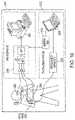
- FIG. 1is a schematic illustration of a system according to an embodiment of the present invention, including internal (chronically implanted) and external components;
- FIG. 2is a perspective view of a stimulation lead for use in the system shown in FIG. 1 , including a detailed view of the distal end of the stimulation lead;
- FIG. 3 Ais a detailed perspective view of the cuff of the stimulation lead shown in FIG. 2 ;
- FIG. 3 Bis a lateral cross-sectional view of the cuff shown in FIGS. 2 and 3 A ;
- FIG. 4 Ais a perspective view of bifurcated respiration sensing lead which may be used in the system shows in FIG. 1 ;
- FIG. 4 A 1is a detailed perspective view of the proximal connector assembly of the respiration sensing lead shown FIG. 1 ;
- FIG. 4 A 2is a detailed perspective view of the bifurcation the section of the respiration sensing lead shown FIG. 1 ;
- FIG. 4 A 3is a detailed perspective view of the contra-lateral distal body portion of the respiration sensing lead shown in FIG. 1 ;
- FIG. 4 A 4is a detailed perspective view of the ipsi-lateral distal body portion in the respiration sensing lead shown in FIG. 1 ;
- FIG. 4 Bis a detailed perspective view of an alternative embodiment of the respiration sensing lead which may be used in the system shown in FIG. 1 ;
- FIG. 41 Bis a detailed perspective view of the proximal connecter assembly of the respiration sensing lead shown in FIG. 4 B ;
- FIG. 4 B 2is a detailed perspective of the distal body portion of the respiration sensing lead shown FIG. 4 B ;
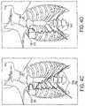
- FIG. 4 Cillustrates the implanted system shown in FIG. 1 with the respiration lead shown in FIG. 4 A ;
- FIG. 4 Dillustrates the implanted system shown in FIG. 1 with the respiration lead shown in FIG. 4 B ;
- FIG. 4 Eillustrates an alternative embodiment of the respiration sensing lead which may be used in the system shown in FIG. 1 ;
- FIG. 4 Fillustrates an alternative embodiment of the respiration sensing lead containing a loop-back region. This lead may be used in the system shown in FIG. 1 ;
- FIG. 4 Gillustrates an alternative embodiment of the respiration sensing lead which may be used in the system shown in FIG. 1 ;
- FIG. 4 Hillustrates an alternative embodiment of the respiration sensing lead which may be used in the system shown in FIG. 1 ;
- FIG. 5 Ashows front, side and top views of an implantable neurostimulator for use in the system shown in FIG. 1 ;
- FIG. 5 Bis a schematic block diagram of electronic circuitry for use in the implantable neurostimulator shown in FIG. 5 A ;
- FIGS. 6 A, 6 B, and 6 Cillustrate a bio-impedance signal, the corresponding physiological events, and stimulation delivery algorithms for use in the system shown in FIG. 1 ;
- FIGS. 6 D, 6 E, 6 F, 6 G, and 6 Hillustrate various stimulation pulse configurations for the implantable neurostimulator shown in FIG. 1 , as may be used for therapy or sleep titration, for example;
- FIG. 6 Ishows various stimulation modes for the implantable neurostimulator shown in FIG. 1 , as may be used for therapy or sleep titration, for example;
- FIG. 6 Jshows a stimulation regimen called core hours for the implantable neurostimulator shown in FIG. 1 , as may be used as a therapy mode;
- FIG. 7 Ais a schematic illustration of the programmer system for use in the system shown in FIG. 1 ;
- FIGS. 7 B and 7 Care schematic block diagrams of electronic circuitry for use in the programmer system for shown in FIG. 7 A ;
- FIG. 8 Ais a schematic illustration of the therapy controller for use in system shown in FIG. 1 ;
- FIG. 8 Bis a schematic diagram of electronic circuitry for use in the therapy controller shown in FIG. 8 A ;
- FIG. 9is a top view of a magnet for use in the system shown in FIG. 1 ;
- FIG. 10is a schematic illustration of an interface of the system shown in FIG. 1 and polysomnographic (PSG) equipment as may be used in a sleep study for therapy titration or therapy assessment, for example;
- PSGpolysomnographic
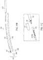
- FIG. 11 Ais an anatomical illustration showing the incision sites and tunneling paths that may be used for implanting the internal components shown in FIG. 1 ;
- FIG. 11 Bis a perspective view of a disassembled tunneling tool for use in tunneling the leads of the system shown in FIG. 1 ;
- FIG. 11 Cis a detailed perspective view of the assembled tunneling tool shown in FIG. 11 B , but with the cap removed to expose the distal connector for attaching to the lead carrier disposed on the proximal end of a lead;
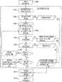
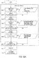
- FIG. 12 Ashows a flowchart of an idealized therapy process and the sub-processes that may be involved
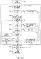
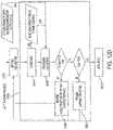
- FIGS. 12 B, 12 C, and 12 Dshow detailed flowcharts of idealized therapy sub-processes shown in FIG. 12 A ;
- FIG. 13(traces 1 - 8 ) illustrate various stimulations output modes of the implantable neurostimulator shown in FIG. 1 ;
- FIG. 14illustrates an example of the effect of stimulation on airflow
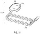
- FIG. 15illustrates a sleep wand, for wireless communication with the neurostimulator during sleep.
- FIG. 1schematically illustrates a hypoglossal nerve stimulation (HGNS) system 100 comprising internal components 1000 and external components 2000 .
- the HGNS system 100treats obstructive sleep apnea (OSA) by increasing neuromuscular activity to the genioglossus muscle via stimulation of the hypoglossal nerve (HGN) synchronous with inspiration to mitigate upper airway collapse during sleep.
- Stimulationis generated by an implantable neurostimulator (INS) 1100 , synchronized with inspiration as measured by the respiration sensing lead (RSL) 1200 using bio-impedance, and deliver to the hypoglossal nerve by a stimulation lead (STL) 1300 .
- INSimplantable neurostimulator
- RSLrespiration sensing lead
- STLstimulation lead
- a programmer system 2100 and a therapy controller 2500are wirelessly linked to the INS 1100 .
- the programmer system 2100 and a therapy controller 2500are wirelessly linked to the INS 1100 .
- the programmer system 2100includes a computer 2300 , a programmer interface 2400 , and a programmer head 2200 .
- the programmer system 2100is used by the physician to control and program the INS 1100 during surgery and therapy titration, and the therapy controller 2500 is used by the patient to control limited aspects of therapy delivery.
- the implanted components 1000 of the HGNS system 100include the INS 1100 , STL 1300 , and RSL 1200 .
- the INSis designed to accommodate one STL 1300 and one RSL 1200 .
- One STL 1300may be used for unilateral implantation and unilateral hypoglossal nerve stimulation.
- one RSL 1200may be used for respiration detection.
- Alternative embodiments of the RSL 1200are described below and may be substituted. Therefore, for purposes of illustration not limitation, the INS 1100 is shown with STL 1300 and a bifurcated RSL 1200 .
- the implanted components 1000may be surgically implanted with the patient under general anesthesia.
- the INS 1100may be implanted in subcutaneous pocket inferior to the clavicle over the pectoralis fascia.
- the distal end of the STL 1300(cuff 1350 ) may be implanted on the hypoglossal nerve or a branch of the hypoglossal nerve in the submandibular region, and the proximal end of the 1300 may be tunneled under the skin to the INS 1100 .
- the RSL 1200may be tunneled under the skin from the INS 1100 to the rib cage and placed on the costal margin.
- the INS 1100detects respiration via the RSL 1200 using bio-impedance.
- FIG. 2schematically illustrates the STL 1300 in more detail.
- the STL 1300is designed to deliver the stimulation signal from the INS 1100 to the hypoglossal nerve and includes a proximal connector assembly 1310 , a main tubular body 1330 , and a distal cuff 1350 .
- the main tubular body of the STLincludes a sigmoid shaped section 1370 and a distal flexible transition section 1380 proximal of the cuff.
- the STLmay have a nominal outside diameter of 0.062 inches to have minimal cosmetic impact, and a nominal overall length of 17.7 inches (45 cm) (including cuff) to extend from the infraclavicular region (INS) to the submandibular region (hypoglossal nerve) and to accommodate anatomical variation.
- the main tubular body 1330 of the STL 1300is designed to withstand gross neck movement as well as mandibular movement and hypoglossal nerve movement caused by talking, chewing, swallowing, etc. To survive in this high fatigue environment, the main tubular body 1330 incorporates a highly compliant silicone jacket in the form of a sigmoid, and two conductors 1390 (one for cathode electrodes, one for anode electrodes) each comprising ETFE insulated MP35N multifilament cable disposed inside the jacket in the form of a bi-filar coil (not visible). This design provides high fatigue resistance and three-dimensional flexibility (bending and elongation).
- the proximal connector assembly 1310is designed to provide a reliable mechanical and electrical connection of the STL 1300 to the INS 1100 . It has a number of strain relief elements that enable it to withstand handling during insertion and removal from the INS 1100 , as well as adverse conditions encountered when implanted.
- the connector assembly 1310includes two in-line stainless steel ring contacts (one for each conductor 1390 ) and two silicone ring seals. STL proximal connector contacts 1310 may have a nominal outside diameter of about 0.122 inches. Set screws in the header of the INS 1100 bear down on the contacts, and together with the ring seals, provide a sealed mechanical and electrical connection to the INS 1100 . As an alternative, wound coil spring contacts may provide mechanical and electrical connections.
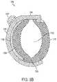
- FIGS. 3 A and 3 BMore detailed views of the cuff 1350 are shown in FIGS. 3 A and 3 B , wherein FIG. 3 A schematically illustrates the cuff 1350 in isometric view, and FIG. 3 B schematically illustrates the cuff 1350 in cross-sectional view.
- the cuff 1350has a hinged oval-shaped silicone body (collectively 1352 and 1354 ) to define an oval lumen 1355 that provides secure and gentle retention around the hypoglossal nerves.
- the cuff 1350may be designed to fit the nerve very closely to minimize tissue growth between the electrode and nerve.
- the cuffis designed to be self-sizing such that different nerve diameters may be accommodated safely. The self-sizing can safely adjust to larger sizes if swelling occurs.
- the cuffmay be available in two sizes to accommodate nerves of different diameter; a small size to accommodate nerves having a diameter of up to about 2.5-3.0 mm, and a large size to accommodate nerves having a diameter of up to 3.0-4.0 mm. At 3.0 mm nerve diameter, either size cuff will fit the nerve with minimal open space for tissue in-growth. Using a large cuff on a 2.5 mm nerve allows clearance between the nerve and electrode which promotes capsule formation between the cuff and nerve. This may cause an increase in capture threshold but will not affect safety. Conversely, a small cuff placed on a large nerve minimizes electrode coverage around the nerve and may fall off with swelling.
- the short side 1352(e.g., 4.0 mm long) of the cuff body fits between nerve branches and connective tissue on the deep side of the nerve, thereby minimization nerve dissection.
- the long side 1354(e.g., 10.0 mm long) of the cuff body rests on the superficial side of the nerve (where few branches exist) and is connected to the transition section 1380 of the main lead body 1330 .
- a silicone strap 1356is connected to and extends from the short side 1352 of the cuff body.
- a silicone top platecomprising an integral base portion 1359 and loop 1358 is attached to and covers the exterior surface of the long side 1354 of the cuff body.
- the strap 1356freely slides through the loop 1358 , and wraps around the long side 1354 of the cuff body.
- the strap 1356is removed from the loop 1358 for placement of the cuff 1350 around the nerve and reinserted into the loop 1358 to hold the cuff 1350 on the nerve.
- a markmay be disposed on the strap 1356 of the small size cuff to indicate that the cuff is too small and that a larger size cuff should be used if the mark does not pass through the loop 1358 .
- the cuff bodyreadily expands along a hinge line 1353 (defined at the junction of the short side 1352 to the long side 1354 ) as well as other portions of the cuff 1350 structure. Expansion of the cuff body accommodates nerves of different diameters and nerve swelling after implantation, while the strap 1356 remains in the loop 1358 to retain the cuff 1350 on the nerve. In the event of excess nerve swelling (e.g., >50% increase in nerve diameter) or traction from the lead 1300 (e.g., as may accidentally occur during implantation), the strap 1356 pulls out of the loop 1358 and releases the cuff 1350 from the nerve to minimize the potential for nerve damage.
- excess nerve swellinge.g., >50% increase in nerve diameter
- traction from the lead 1300e.g., as may accidentally occur during implantation
- the cuff bodycarries four platinum-iridium electrodes 1360 (e.g., 2.0 mm 2 exposed area each for small cuff, 3.0 mm 2 exposed area each for large cuff), with one cathode electrode 1360 on the short side 1352 , another cathode electrode 1360 (not visible) diametrically opposed on the long side 1354 , and two anode electrodes 1360 guarding the cathode electrode 1360 on the long side 1354 .
- This guarded dual cathode arrangementprovides a more uniform electrical field throughout the cross-section of the nerve while minimizing electrical field outside of the cuff.
- One conductor 1390may be connected to the cathode electrode 1360 on the long side, to which the other cathode electrode 1360 on the short side is connected by a jumper wire.
- the other conductor 1390may be connected to the distal anode electrode 1360 , to which the proximal anode electrode 1360 is connected by jumper wire.
- the cathode electrodesare commonly connected to one conductor 1390 and the anode electrodes are commonly connected to the other conductor 1390 .
- all external surfaces of the STL 1300 exposed to the body when implantedmay comprise implantable grade polymers selected from the following: silicone, and fully cured silicone adhesive.
- the metal electrode contacts in the cuffmay comprise implantable grade platinum-iridium and are secured to the silicone cuff body with silicone adhesive, for example.
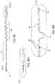
- FIGS. 4 A- 4 Gschematically illustrates the respiration sensing lead (RSL) 1200 in more detail.
- the respiration sensing lead 1200is designed to measure bio-impedance and includes a proximal portion with a proximal connector assembly 1210 , a proximal tubular body 1220 ending in a bifurcation section 1280 , and ipsi-lateral and contra-lateral distal portions extending from the bifurcation section.
- Each distal portionmay include a tubular body 1220 , a proximal sigmoid section 1230 , a distal sigmoid section 1240 , one or more current injection ring electrodes 1250 , one or more voltage sensing ring electrodes 1260 , anchor tabs 1270 , and a suture hole 1290 in the most distal ring electrodes.
- the ring electrodes 1250 and 1260may be dual-function, such that each electrode may function as either a current emitting electrode or voltage sensing electrode.
- the ipsi-lateral distal portionmay contain three ring electrodes, the most distal being a current emitting electrode 1250 and containing a suture hole 1290 , and the other two electrodes being voltage sensing electrodes 1260 .
- the contra-lateral distal portionmay contain two ring electrodes, the distal being a current emitting electrode 1250 and containing a suture hole 1290 , and the proximal a voltage sensing electrodes. It may be advantageous to have the suture holes in the most distal ring electrodes since no wires pass through this point and because this provides a robust anchor point for the electrode to be sutured on the costal margin muscle fascia.
- the RSL 1200may have a nominal outside diameter of about 0.072 inches to have minimal cosmetic impact.
- the RSL proximal connector contacts 1210may have a nominal outside diameter of about 0.122 inches (same as the STL proximal connector contacts 1310 ).
- the distal ring electrodesmay also have a nominal outside diameter of 0.122 inches. This uniformity in diameters may be advantageous, allowing the same lead carrier 3100 to place both STL 1300 and RST 1200 leads for tunneling.
- the distance from the tip of the proximal connector 1210 to the bifurcation section 1280may have an overall length of 8.9 inches (22.5 cm).
- the distance from the bifurcation section 1280 to the ipsi-lateral proximal anchor tab 1270may be 9.6 inches (24.4 cm) unstretched and 12.2 inches (31 cm) stretched.
- the distance from the bifurcation section 1280 to the contra-lateral proximal anchor tab 1270may be 13.5 inches (34.3 cm) unstretched and 16.1 inches (41 cm) stretched.
- the distance from the proximal anchor tab 1270 to the distal suture hole 1290may be 2.8 inches (7 cm) unstretched and 3.1 inches (8 cm) stretched on both the contra-lateral and ipsi-lateral distal portions.
- the RSL 1200may extend from the infraclavicular region (where the INS 1100 is implanted) to the ipsi-lateral and contra-lateral thorax where the RSL 1200 may be implanted to accommodate anatomic
- the bifurcated RSL 1200 designenables one RSL 1200 to sense bio-impedance on the contra-lateral and ipsi-lateral sides of the thorax. Two RSLs 1200 , one on each side of the patient's chest, may also achieve this.
- the bifurcated designachieves this result while reducing the number of implanted components and reducing volume of the INS header 1110 since only one RSL port 1112 is required.
- the main tubular lead of the RSL 1200is designed to withstand thoracic movement due to flexion, extension, rotation and breathing.
- the main tubular body 1220may include a flexible silicone jacket formed such that each distal end has two sigmoid sections 1230 and 1240 , and conductors comprising small diameter ETFE insulated MP35NLT cables (not visible) disposed inside the jacket.
- An injection molded Y-fitting (yoke)connects the proximal portion of the RSL 1200 to the distal portions, creating the bifurcation section 1280 .
- Conductors, here five,are continuously fed from the connector assembly through the proximal tubing body 1220 and proximal portion of the Y-fitting.
- the tubing bodiesmay be adhesively bonded or molded to the Y-fitting.
- the number of conductorsmay equal the number of contacts in the INS header 1112 , here five. Two of the conductors, one on each side, may connect proximally to current emitting header contacts, (e.g., R1 and L1), and terminate distally in current emitting electrodes 1250 .
- Three of the conductorsmay connect proximally to voltage sensing header contacts (e.g., R2, R3, and L3) and terminate distally in voltage sensing electrodes.
- dual-function electrodesmay enable any electrode (ring electrode 1250 or 1260 ) to emit current or sense voltage. This switching may occur via components on the INS circuit board 1130 .
- a bridgemay be formed joining two contacts in the proximal connector assembly such that the corresponding electrode may function as either a current emitting electrode 1250 or voltage sensing electrode 1260 .
- Dual-function electrodesenable more vectors in an implanted region without additional electrodes.
- the proximal sigmoid section 1230isolates movement of the INS 1100 from the electrodes 1250 and 1260 , and accommodates anatomic variations in thoracic length.
- the distal sigmoid section 1240allows adjustment in the distance between electrodes 1250 and 1260 , and reduces strain applied between the anchor tabs 1270 , which may be secured with sutures to the underlying fascia when implanted.
- the proximal sigmoid 1230 sectionmay have 5 wavelengths with an outside peak-to-peak dimension of approximately 0.84 inches (2.1 cm) and an overall length of 7.0 inches (17.8 cm).
- the distal sigmoid 1240 sectionmay have half a wavelength with a center-to-center peak-to-peak dimension of approximately 0.43 inches (2.1 cm) and an overall length of 0.869 inches (2.2 cm).
- the two distal portions' electrodes 1250 and 1260may comprise five electrodes total, and each may comprise MP35N rings having an exposed surface area.
- the distal electrode containing a suture hole 1290may have an exposed surface area of 73.8 mm 2 including the suture hole 1290 , and 66.4 mm 2 not including the suture hole 1290 .
- the proximal electrode containing an anchor tab 1270may have an exposed surface area of 305 mm 2 and the electrode without an anchor tab may have an exposed surface area of 32.0 mm 2 .
- Tubular strain relief segmentsmay be disposed on the lead body on either side of electrode 1250 or 1260 .
- strain relief segmentsare adjacent to each other, a gap may be provided there between the strain relief segments or the segments may abet one another to avoid a stress concentration point. Strain reliefs may also be disposed on each end of the electrodes 1250 or 1260 to avoid stress concentration points.
- the anchor tab 1270may be disposed over an electrode leaving the proximal and distal extremities of the electrode exposed.
- the INS 1100detects impedance along a vector, with each end of the vector defined by a current delivery electrode 1250 and a voltage sensing electrode 1260 .
- a small excitation currentis delivered between the two current emitting electrodes 1250 , and the corresponding change in voltage is measured by the two voltage sensing electrodes 1260 .
- the INS housing 1120may also act as a current emitting and/or voltage sensing electrode, or contain smaller current emitting and/or voltage sensing electrodes on its surface. Changes in impedance are calculated by dividing the change in voltage by the excitation current, which correspond to movement of the diaphragm, lung, and other tissues to produce a signal indicative of respiratory activity.
- the proximal connector assembly 1210 of the RSL 1200is designed to provide a reliable mechanical and electrical connection of the RSL 1200 to the INS 1100 . It has a number of strain relief elements that enable it to withstand handling during insertion and removal from the INS 1100 , as well as adverse conditions encountered when implanted.
- the connector assembly 1210may include five in-line stainless steel ring contacts (one for each conductor) and five silicone ring seals. Set screws in the header of the INS 1100 bear down on the contacts, and together with ring seals, provide a sealed mechanical and electrical connection to the INS 1100 . Ring seals may be part of the RSL 1200 or the INS header 1110 .
- all external surfaces of the RSL 1200 exposed to the body when implantedmay comprise implantable grade polymers selected from the following: silicone, and fully cured silicone adhesive.
- the distal electrodesmay comprise implantable grade MP35N and are sealed to the lead body with silicone adhesive, for example.
- respiration sensing lead designsmay be employed to provide at least one bio-impedance vector (current injection electrode pair and voltage sensing electrode pair) from a point along the costal margin to a point along the opposite (trans-lateral) costal margin, to a point along the same side (ipsi-lateral) costal margin, or to a point in the infraclavicular region, as seen in FIG. 4 C .
- a bio-impedance vectorcurrent injection electrode pair and voltage sensing electrode pair
- FIG. 4 Ban alternative embodiment of the RSL 1200 is shown in FIG. 4 B , wherein the bifurcation section 1250 and contra-lateral distal portion are eliminated.
- the lead bodymay contain three conductors.
- the connector assembly 1210may include three in-line stainless steel ring contacts (one for each conductor) and three silicone ring seals.
- the RSLmay have an overall length of 21.2 inches (53.9 cm).
- the distance from the proximal tip of the proximal connector assembly 1210 to the first sigmoidmay be 9.5 inches (24.1 cm).
- the proximal sigmoid 1230 sectionmay have 5 wavelengths with an outside peal-to-peak dimension of approximately 0.84 inches (2.1 cm) and an overall length of 7.0 inches (17.8 cm).
- the distal sigmoid 1240 sectionmay have a 1 ⁇ 2 wavelength with a center-to-center peak-to-peak dimension of approximately 0.43 inches (2.1 cm) and a length of 0.869 inches (2.2 cm).
- the RSL 1200may be implanted ipsi-laterally on the ipsi-lateral costal margin, a less invasive surgery, while maintaining vectors from the ipsi-lateral costal margin to the infraclavicular region, see FIG. 4 D .
- the RSL 1200may contain four electrodes, one or more of which can function as either a current emitting electrode 1250 or voltage sensing electrode 1260 , as described previously.
- thisis achieved by exposing the conductor of the bi-functional electrode to two contacts (one voltage sensing, one current emitting) in the INS header 1110 , and selecting only one contact for sensing.
- this functionalitymay be built into the INS circuit board 1130 .
- These embodiments of the RSL 1200may be implanted ipsi-laterally (e.g. on the right costal margin), which is a less invasive surgery, while maintaining vectors from the ipsi-lateral costal margin to the infraclavicular region.
- FIG. 4 Eillustrates a straight four electrode RSL 1200 . This is similar in design to the RSL 1200 of FIG. 4 B , wherein there are a first, second, third, and fourth electrodes, from proximal to distal.
- FIG. 4 Fillustrates a four electrode RSL 1200 with a loop back region 1255 .
- the lead bodyruns in the medial direction, then loops back in the lateral direction.
- the loop back region 1255may act as a strain relief and allow the medial anchor tab 1270 to be sutured at the intersection of the two tunneling paths (from INS incision to medial incision, and between two RSL incisions). This may allow the RSL 1200 to lie in an unbiased preferred configuration along the costal margin.
- the first and third most distal electrodesare current emitting
- the second, third, and fourth most distal electrodesare voltage sensing.
- FIG. 4 Gillustrates a four electrode RSL 1200 with a bifurcation section 1280 created by a T-fitting.
- An injection molded T-fittingconnects the proximal portion of the RSL 1200 to the distal portions, creating the bifurcation section 1280 .
- Conductors, here four,are continuously fed from the connector assembly through the proximal tubing body 1220 and proximal portion of T-fitting. Two of these conductors continue through the proximal distal portion of the T-fitting to the proximal distal tubing body of the RSL. The other two conductors continue through the medial distal portion of the T-fitting and to the medial distal tubing body of the RSL.
- the tubing bodiesmay be adhesively bonded or molded to the T-fitting.
- the anchor tab 1270may be adhesively bonded to the bifurcation section 1280 . Again, this may allow the RSL 1200 to lie in an unbiased preferred configuration along the costal margin.
- the T-fittingmay act as a strain relief. Both medial and lateral distal electrodes may contain suture holes 1290 .
- FIG. 4 Hillustrates an alternative embodiment of the RSL 1200 , wherein the RSL 1200 has an overall L-shape.
- the first and fourth electrodesmay be current emitting electrodes 1250 .
- the second and third electrodesmay be voltage sensing electrodes 1260 .
- the lead bodymay contain four conductors.
- the connector assembly 1210may include four in-line stainless steel ring contacts (one for each conductor) and four silicone ring seals.
- the proximal portion of the RSL 1200(including the proximal connector and proximal sigmoid) may have an overall length of 17.0 inches (43.2 cm).
- the distance from the proximal tip of the proximal connector assembly 1210 to the first sigmoidmay be 11.1 inches (18.1 cm).
- the proximal sigmoid 1230 sectionmay have 4.5 wavelengths, each wavelength 1.25 inches (3.2 cm), and with an outside peak-to-peak dimension of approximately 0.84 inches (2.1 cm).
- the distal portion of the RSL 1200(from the distal end of the proximal sigmoid 1230 to the distal suture hole 1290 ) may have an overall length of 4.9 inches (12.5 cm).
- the length from the distal end of the proximal sigmoid 1230 to the proximal end of the distal sigmoid 1240may be 2.2 inches (5.7 cm).
- the length from the distal end of the distal sigmoid 1240 to the distal suture hole 1290may be 1.8 inches (4.6 cm).
- the distal sigmoid 1240 sectionmay have a center-to-center peak-to-peak dimension of approximately 0.92 inches (2.3 cm).
- the RSL 1200may be implanted ipsi-laterally on the ipsi-lateral costal margin, a less invasive surgery, while maintaining vectors from the ipsi-lateral costal margin to the infraclavicular region.
- Implantable NeurostimulatorINS
- FIG. 5 Aschematically illustrates the INS 1100 in more detail, including a front view, a top view and a side view.
- the INS 1100is similar in certain aspects to commercially available implantable pulse generators and implantable neurostimulators, which may be obtained from suitable manufacturers such as CCC Medical Devices (Montevideo, convinced).
- the INS 1100generally includes a header 1110 for connection the STL 1300 and RSLs 1200 , and a hermetically sealed housing 1120 for containing the associated electronics 1130 , a battery 1140 (e.g., Greatbatch 9086), and an accelerometer 1150 .
- the INS 1100may contain an oxygen sensor (e.g., SaO 2 , SpO 2 , ion, etc.). Alternatively, the oxygen sensor may be incorporated in a lead with connection to the INS 1100 .
- an oxygen sensore.g., SaO 2 , SpO 2 , ion, etc.
- the electronic circuitry 1130 contained in the INS 1100enables telemetry communication with the programmer system 2100 and therapy controller 2500 , detection of respiration via the RSL 1200 , determination of the start time and duration of a stimulation signal, and delivery of a controlled electrical stimulation signal (pulse train) via the STL 1300 .
- the INS 1100also records therapy history data (device settings, status, measured data, device use, respiration data, stimulation delivery data, statistics based on measured signals, etc.).
- the header 1110may comprise epoxy that is hermetically sealed to the housing 1120 .
- the housing 1120may comprise titanium.
- the housing 1120may be used as an electrode for bio-impedance respiration measurement.
- electrodes 1360may be used as an electrode for bio-impedance respiration measurement.
- the housing 1120may comprise a combination current emitting and voltage sensing electrode for respiration detection.
- separate electrodesmay be included in the header of the device from which to sense or stimulate.
- the header 1110includes two ports: one RSL port 1112 (labeled “sense”) for receiving the proximal connector of the RSL 1200 and one STL port 1114 (labeled “stim”) for receiving the proximal connector of the STL 1300 .
- the port configured to receive a STL 1300includes two set screws (labeled “ ⁇ ” for cathode and “+” for anode) with associated set screw blocks and seals for mechanical and electrical connection to corresponding contacts on the proximal connector 1310 of the STL 1300 .
- the port that is configured to receive a RSL 1200includes five set screws (two labeled R1 and L1 for current emitting electrodes and three labeled R2, R3, and L3, for voltage sensing electrodes) with associated set screw blocks and seals for mechanical and electrical connection to corresponding contacts of the proximal connector 1210 of the RSL 1200 . Seals are located between electrical contacts as well as between the distal-most electrical contact and the remainder of the proximal connector assembly 1210 . These seals electrically isolate each contact.
- wound coil spring contactsmay provide electrical connections between the INS header 1110 and the proximal connector assemblies 1210 and 1310 .
- one electrical connectionis still achieved with a set screw which also serves to hold the connector assembly in place.
- This embodimentprovides a sealed mechanical and electrical connection of the RSL 1200 and STL 1300 to the INS 1100 .
- An example of this technologyis Bal Seal's Canted CoilTM Spring Technology.
- the header 1110further includes two suture holes 1116 for securing the INS 1100 to subcutaneous tissue such as muscle fascia using sutures when implanted in a subcutaneous pocket.
- suture holes 1116for securing the INS 1100 to subcutaneous tissue such as muscle fascia using sutures when implanted in a subcutaneous pocket.
- the INS 1100generates the stimulation output for delivery to the hypoglossal nerve by way of the STL 1300 .
- the INS 1100has a bipolar stimulation output channel corresponding to the STL port 1114 , with the channel providing a pulse train of biphasic constant current pulses with a frequency range of 20 to 50 Hz, a pulse width range of 30 to 215 ⁇ s, an amplitude range of 0.4 to 5.0 mA, and a stimulation duty cycle range of 41%-69%, by way of example, not limitation.
- the INS 1100also generates the excitation signal and measures voltage by way of the RSL 1200 for bio-impedance respiration detection.
- the INS 1100also has two respiration sensing channels for simultaneous acquisition of bio-impedance sensing on different vectors. This may be achieved by sequential or alternating sampling of different vectors.
- the INS 1100measures bio-impedance via the RSL port 1112 , with each channel providing a small excitation current (“I”) and measuring voltage (“V”).
- the excitation signalmay comprise a 10 Hz biphasic constant current pulse, with the positive and negative phases of each biphasic pulse having amplitude of 450 ⁇ A, duration of 80 ⁇ s, and charge of 36 nC.
- Current (“I”)may be fixed, allowing voltage (“V”) to be a relative measure of impedance (“Z”), which corresponds to movement of the diaphragm, lung, and other structures to produce a signal indicative of respiratory activity.
- the INS circuit 1130utilizes a microprocessor to control telemetry communications with the programmer system 2100 , operating the sensing circuits to monitor respiration via the RSL 1200 , controlling the delivery of output stimuli via the STL 1300 , monitoring the accelerometer, magnetically sensitive reed switch and the real-time clock.
- the microprocessorcontains built-in support circuits (RAM, flash memory, analog to digital (A/D) converter, timers, serial ports and digital IO) used to interface with the rest of the INS circuit 1130 , including the accelerometer 1150 .
- Two microprocessors communicating via a serial linkmay be used instead of one microprocessor, with the first microprocessor for telemetry communications, monitoring the accelerometer, magnetically sensitive reed switch and the real-time clock; and the second microprocessor for operating the sensing circuits and controlling the delivery of output stimuli.
- a single microprocessorcould perform these functions.
- the telemetry interface circuitsconsist of a tuned telemetry coil circuit and a telemetry driver/receiver circuit to allow pulse encoded communication between the external programmer system 2100 and the microprocessor.
- RF antennae with associated circuitrymay be used to establish a RF link to provide for arms-length telemetry.
- the reed switchprovides a means for the INS 1100 to be controlled by using a magnet placed in close proximity thereto.
- the real-time clockprovides the basic time base (768 Hz) for the INS circuit 1130 as well as a clock (year, day, hour, minute, second) which can be used to control the scheduled delivery of therapy.
- the clockis also used to time stamp information about the operation of the system that is recorded on a nightly basis.
- the respiratory sensing circuitis comprised of two main parts: the excitation current source (output) and the voltage sensing circuit (input).
- respirationis detected via the RSL 1200 using a 3 or 4-wire impedance measurement circuit.
- an excitation currentis driven through a pair of electrodes, and the resulting voltage is measured on a separate pair of electrodes.
- the electrode switching circuitsallow the INS 1100 to monitor one of several different vectors from the RSL electrodes 1250 and 1260 .
- each physical electrodemay function as a current emitting electrode 1250 or a voltage sensing electrode 1260 , depending on the programmable vector configuration.
- the INS housing 1120may be used as both an excitation and sensing electrode.
- the excitation current circuitdelivers biphasic pulses of low level (450 uA) current to the selected electrode pair every 100 ms during sensing.
- the voltage sensing amplifier circuitsynchronously monitors the voltage produced by the excitation current on the selected electrode pair.
- the resulting output signalis proportional to the respiratory impedance (0.07 ⁇ to 10 ⁇ ) and is applied to the A/D circuit in the microprocessor for digitization and analysis.
- the stimulation output circuitsdeliver bursts of biphasic stimulation pulses to the STL 1300 . These bursts may be synchronized to the sensed respiratory waveform to deliver stimulation and thus airway opening at the appropriate time.
- the stimulation output circuitsinclude an electrode switching network, a current source circuit, and an output power supply.
- the electrode switching networkalso allows for a charge balancing cycle following each stimulation pulse during which the outputs are connected together with no applied output pulse.
- the timing and polarity of the pulse deliveryis provided by control outputs of the microprocessor.
- the microprocessorselects the amplitude (e.g., 0.4 mA to 5 mA) of the output current from the current source circuit which is applied through the switching network.
- the output power supplyconverts battery voltage to a higher voltage (e.g., 5V to 14V) which is sufficient to provide the selected current into the load impedance of the STL 1300 .
- the microprocessormeasures the voltage output from the electrode switching network resulting from the delivered current and the load impedance.
- the microprocessordivides the output voltage by the output current resulting in a measure of the load impedance (400 ⁇ to 2700 ⁇ ) which can be an indicator of integrity of the STL 1300 .
- the INS 1100may contain an oxygen sensor to monitor oxygen levels, for example during a therapy session. This may be used to monitor efficacy as well to set stimulation settings during a therapy session.
- the INS 1100may be programmed to increase stimulation when oxygen de-saturations are detected at a programmable threshold rate and/or severity.
- the INS 1100may turn stimulation on once de-saturations are detected, wherein thresholds of rate and severity are programmable. Desaturations may act to indicate the sleep state or wakefulness.
- electroneurogram (ENG)may be used to monitor nerve activity, which may also be indicative of sleep state and/or wakefulness.
- the INS 1100may use the indication of sleep state or wakefulness to change stimulation settings. For example, stimulation may be increased when the patient is in N3 or REM sleep. In addition, stimulation level may be decreased or turned off during stage N1, N2, or wakefulness.
- the INS 1100 circuitrymay contain a three-axis accelerometer 1150 that can be used to determine the patient's body position (supine, prone, upright, left, or right side) and/or detect motion events (wakefulness). These data may be used to change stimulation settings or inhibit output.
- the INS 1100may be programmed to increase stimulation intensity when the patient is in specific body positions (e.g., supine, a more challenging position).
- the INS 1100may segregate recorded therapy statistics (e.g., cycling detector events, oxygen desaturations) with respect to body position. For example, a patient's cycling detector may record very few events in the lateral position and many events in the supine position, indicative of the patient being treated in the lateral position.
- the bio-impedance respiration signal. (“Z”)which is generated by dividing the change in measured voltage (“V”) by the excitation current (“I”), tracks with diaphragm movement (DM) over time and therefore is a good measure of respiratory activity, and may be used to measure respiratory effort, respiratory rate, respiratory (tidal) volume, minute volume, etc. if the excitation current (I) is constant or assumed constant, then the bio-impedance (Z) is proportional to the measured voltage (V), and thus the voltage (V) may be used as a surrogate for bio-impedance (Z), thereby eliminating the division step.
- diaphragm movementincludes movements and shape changes of the diaphragm and adjacent tissue that occur during normal breathing and during obstructed breathing.
- the bio-impedance waveformmay be filtered to reduce noise and eliminate cardiac artifact, clarifying positive and negative peak occurrence.
- the signalmay be filtered using a first order low pass filter. Alternatively, a higher order curve fit approach could be utilized to filter the signal.
- the (positive or negative) peak (P) of the impedance signal (Z)corresponds to the end of the inspiratory phase and the beginning of the expiratory phase. If the signal is normal (as shown), the positive peak is used; and if the signal is inverted, the negative peak is used.
- the impedance signalprovides a reliable fiducial (P) for end-inspiration and begin-expiration (also called expiratory onset), but may not provide a readily discernable fiducial for begin-inspiration (also called inspiratory onset). Therefore, algorithms described herein do not rely on begin-inspiration (or inspiratory onset) to determine the start of stimulation bursts as proposed in the prior art, but rather use a more readily discernable fiducial (P) corresponding to begin-expiration (or expiratory onset) in a predictive algorithm as described below. Other non-predictive (e.g., triggered) algorithms are described elsewhere herein.
- Gross body motionis often indicative of patient wakefulness and may change the bio-impedance signal (Z).
- a motion eventmay be detected, for example, by assessing variability in the bio-impedance peak-to-peak signal strength (P-P). Different thresholds of sensitivity may be utilized such that minor movements are not grouped with motion events.
- P-Pbio-impedance peak-to-peak signal strength
- Different thresholds of sensitivitymay be utilized such that minor movements are not grouped with motion events.
- stimulationmay be turned off or turned down until motion stops or for a programmable duration of time. The frequency and duration of these motion events may be recorded in device history.
- the accelerometer 1150could be utilized in a similar fashion to detect and record motion events
- Waxing and waning of the bio-impedance signal (Z)is often indicative of apneas or hypopneas.
- this patternmay be detected, for example, by assessing trends of increasing and decreasing average P-P amplitude values. Different thresholds of sensitivity may be utilized such that minor changes in P-P values are not declared cycling events.
- stimulation parametersmay be initiated or changed (e.g., increased intensity, increased duty cycle, etc.) to improve therapy.
- the frequency and duration of these cyclic breathing patternsmay be recorded in therapy history. These values may be used as an indicator of how well the patient is being treated, providing an estimate of AHI.
- the INS 1100may be programmed to change stimulation level between therapy sessions, days, or other programmable value.
- the stimulation levelmay be recorded alongside therapy session data, for example cycling rate (via the cycling detector), oxygen desaturation frequency and severity, stimulation time, variations in respiratory rate, variations in respiratory prediction, etc.
- inspirationis typically 25-50% of the respiratory cycle, with variations in respiration rate being common. Variations may cause actual inspiration to differ from predicted inspiration.
- the hypoglossal nerveusually activates approximately 300 ms before inspiration and remains active for the entire inspiratory phase. To mimic this natural physiology, it is desirable to deliver stimulation to the hypoglossal nerve during the inspiratory phase plus a brief pre-inspiratory period of about 300 ms. To maximize stimulation coverage of actual inspiration, it may be advantageous to account for this variability by centering stimulation on the predicted inspiration. As mentioned previously, there are reliable fiducials for the beginning of the expiratory phase (peak P) which may be used to deliver stimulation to cover the inspiratory phase plus brief pre and/or post-inspiratory periods.
- an algorithmis used to predict respiratory period and determine the start of the stimulation burst.
- the predictive algorithmis contained in software and executed by a microprocessor resident in the INS circuitry 1130 , thus enabling the INS 1100 to generate stimulation synchronous with inspiration.
- a prediction algorithmuses the respiratory period of previous breaths to predict the respiratory period of each subsequent breath.
- a respiratory periodis determined by calculating the time between peaks in the bio-impedance signal (Z). If the actual respiratory period is different from the predicted respiratory period, then the subsequent predicted respiratory period is re-synchronized and updated to equal the actual period, up to a programmable value (e.g., 300 ms). If the difference in respiratory period exceeds the programmable value, then the predicted respiratory period is incremented or decremented by this value.
- the stimulation periodis centered about a percentage (e.g., 75%) of the predictive respiratory period.
- the predictive algorithmuses historical peak data (i.e., begin-expiration data) to predict the time to the next peak, which is equivalent to the predicted respiratory period.
- the stimulation periodis centered at 75%, for example, of the predicted respiratory time period.
- a phase adjustment parameterrange: +/ ⁇ 1000 ms, for example) permits the stimulation period to be biased early or late.
- FIG. 6 CA feature common to the predictive algorithms is illustrated in FIG. 6 C .
- This featureprovides a sequence of predicted respiratory periods in case the respiration impedance signal (“Z”) is temporarily lost (e.g., due to change in respiratory effort). Until a subsequent respiratory peak is detected, stimulation parameters which are based on the measured respiratory period (e.g., stimulation period) are unchanged. Thus, stimulation timing remains synchronous to the last detected peak.
- the stimulation duty cyclemay be fixed or adaptive.
- the stimulation duty cycleis set using to programmer system 2100 to a fixed percentage value. This fixed value may be increased when the respiratory signal is lost, increasing the likelihood of aligning with actual inspiration.
- adaptive modethe duty cycle is allowed to vary as a function of a characteristic of respiration. For example, the adaptive duty cycle may increase when prediction is less accurate (higher variability in respiration rate) or when the respiratory signal is lost.
- the stimulation duty cyclemay run above normal (e.g., above 50% to 60%) to achieve a better likelihood of covering the inspiratory phase.
- above normal stimulation duty cyclemay result in nerve and/or muscle fatigue if prolonged, it may be desirable to offset above-normal stimulation periods with below-normal stimulation periods to result in a net normal duty cycle.
- the stimulation duty cyclemay be reduced.
- the maximum stimulation duty cyclemay be set from 41% to 69% in 3% increments, and the default setting may be 50%.
- adaptive modethe stimulation duty cycle for a respiratory period may vary from 31% to 69% in 3% increments, and the maximum running average may be set to 53%.
- the adaptive modeallows the duty cycle to decrease when respiratory period is stable and increase with respiratory period variability, for example, and the stimulation duty cycle may run in excess of 53% for a limited period of time, but those periods are proportionally offset by periods where the stimulation duty cycle runs less than 53% (e.g., according to an exponentially weighted moving average).
- an adaptive duty cycle set to 69%would run at that level for no longer than 5 to 7 minutes before being offset by a lower stimulation duty cycle at 47% to result in a running average of 53%.
- This equationis approximate and may vary slightly depending on the averaging technique used. Other offset methods may be used as an alternative.
- the stimulation duty cyclemay be nominally 50%.
- a duty cycle limitermay be enabled such that it prevents the device from exceeding a programmable long term average stimulation duty cycle threshold (e.g., 53%).
- Long term average duty cyclemay be calculated using a first order filter of duty cycle measured over a fixed time period (e.g., 6 seconds), with a programmable filter time constant (e.g., each iterative calculation is given a weighting of 1/32). If the long term average duty cycle reaches the programmable threshold, then stimulation duty cycle is decreased to a programmable value, (e.g., 44%) until the long term average drops below the nominal value (here, 50%), at which time the nominal duty cycle is restored.
- This safety mechanismmay prevent nerve and muscle fatigue.
- the INS 1100may deliver stimulation as a train of pulses with constant pulse width and amplitude at a set frequency for a duration limited by duty cycle.
- This train of pulsesmay be described as a pulse train envelope and is illustrated in FIG. 6 D .
- the envelopedescribes a series of biphasic pulses delivered consecutively during a stimulation burst. When the stimulation level of the positive phase of each biphasic pulse is uniform, this level is the level of the stimulation burst.
- the INS 1100may also deliver stimulation in pulse train envelopes wherein the pulses are non-uniform (e.g., pulses, may have different amplitudes).
- the muscle(s) activated by the stimulationmay not require the full stimulation intensity for the duration of the stimulation in order to maintain muscle contraction.
- the INS 1100may be programmed to deliver a basic retention intensity pulse configuration, defined as a pulse train envelope wherein each pulse's intensity (e.g., amplitude) is less than or equal to the previous pulse's intensity, (e.g., a two second pulse wherein the first 1000 ms is at 2 mA and the subsequent 1000 ms is at 1.7 mA).
- This pulse configurationis illustrated in FIG. 6 E . This allows the muscle to activate to a level and then remain in that position with a less intense stimulation.
- the pulse levelcould be decreased gradually during each burst (rather than abruptly) to reach the same final stimulation level.
- the INS 1100may be programmed to deliver a soft start pulse configuration, defined as a pulse train envelope wherein at the start of each burst, each pulse's intensity (e.g., amplitude) is greater than or equal to the previous pulse's intensity, (e.g., a two second pulse wherein the first 100 ms is at 1.85 mA, the second 100 ms is at 1.95 mA, the third 100 ms is at 2.05 mA and the remaining 1700 ms is at 2.1 mA).
- a soft start pulse configurationdefined as a pulse train envelope wherein at the start of each burst, each pulse's intensity (e.g., amplitude) is greater than or equal to the previous pulse's intensity, (e.g., a two second pulse wherein the first 100 ms is at 1.85 mA, the second 100 ms is at 1.95 mA, the third 100 ms is at 2.05 mA and the remaining 1700 ms is at 2.1
- a pulse train envelopemay employ a soft start to reach full stimulation and subsequently decrease intensity (amplitude) to a retention intensity for the remainder of the stimulation, (e.g., a two second pulse, wherein the first 100 ms, is at 1.85 mA, the second 100 ms is at 1.95 mA, the third 100 ms is at 2.05 mA, and the next 700 ms is at 2.1 mA, and the remaining 1000 ms is at 1.8 mA).
- This pulse configurationis illustrated in FIG. 6 F .
- This configurationmay provide the benefits of both soft start and retention intensity, wherein the stimulation starts gradually to fully activate the muscle(s), then decreases to a level of less intense stimulation, with the muscle remaining in a contracted position.
- FIG. 6 Hshows nested mode, a simplified version of the previously mentioned retention intensity, wherein there is one step up to the full amplitude, and then an equal step down to the retention intensity.
- the INSprovides two separate stimulation strengths (A & B) with independent parameters (amplitude, pulse width, frequency, duty cycle and phase adjust). Stimulation may be delivered in different therapy modes, examples of which are shown in FIG. 6 I .
- FIG. 6 I(traces 1 - 8 ) illustrates some commonly used modes, all of which are inspiratory synchronous, meaning stimulation is automatically delivered according to an algorithm that predicts the inspiratory phase and initiates stimulation delivery at a desired time relative to inspiration, such as centered on the predicted inspiration.
- These modesmay be used as standard therapy as well as to determine device settings during a PSG (e.g. sleep titration PSG). Additionally, these modes may be used to diagnose phenotypes of OSA or other diseases.
- FIG. 6 Iillustrates synchronous mode in which every stimulation has the same pulse configuration and amplitude, known as AAAA mode, the default therapy mode.
- AAAA modemeans that four consecutive inspirations are covered by stimulation of level A, where A is 2.0 mA, for example. Inspiration is show in FIG. 6 I (trace 9 ) in the upward direction.
- the inspiratory-synchronous ARAB modealso delivers stimulation bursts synchronous with inspiration as determined by the device, therapy delivery algorithm settings, and sensed respiratory signal.
- This modeis similar to AAAA mode, except that the stimulation is delivered on four consecutive inspirations alternating between stimulation levels A and B on each burst where, for example, A is 2.0 mA and B is 1.8 mA.
- FIG. 6 Iillustrates a subset of ARAB mode known as A0A0 mode, wherein the B breath is not stimulated.
- Amay be 2.0 mA and B may be 0 mA, for example.
- FIG. 6 Iillustrates A0B0 mode, wherein a first breath is stimulated at level “A,” followed by an second breath that is unstimulated, followed by a third breath that is stimulated at level “B,” followed by a fourth breath that is unstimulated, (e.g., A is 2.0 mA and B is 1.8 mA). This allows for simultaneous assessment of two different levels (A and B) when compared to adjacent non-stimulated breaths.
- FIG. 6 Iillustrates AABB mode wherein two breaths are stimulated at level “A” followed by two breaths stimulated level “B,” (e.g., A is 2.0 mA and B is 1.8 mA). In this mode, every stimulated breath is adjacent to a stimulated breath at level “A” and a stimulated breath at level “B.”
- the AABB modemay be used to test if there is a short-term residual cross-over effect when changing from one stimulation level to another stimulation level or from a stimulation level to no stimulation. For example, the airflow measured during the first “A” can be compared to the airflow measured during the second “A” in each sequence over many periods to determine if there is a measurable residual effect from the “B” level simulation.
- FIG. 6 Iillustrates xAB0 mode, wherein “x” number of breaths are stimulated at level “A,” followed by a breath stimulated at level “B,” followed by an unstimulated breath, (e.g. A is 2.0 mA and B is 1.8 mA).
- the illustrationshows x equals 3 (3AB0), although x may be any number of breaths (e.g., 3, 5, 7).
- FIG. 6 Iillustrates xA0B mode, wherein “x” number of breaths are stimulated at level “A,” followed by an unstimulated breath, followed by a breath stimulated at level “B,” (e.g., A is 2.0 mA and B is 1.8 mA).
- the illustrationshows x equals 3 (3A0B), although x may be any number of breaths (e.g., 5, 7).
- FIG. 6 Iillustrates xAB mode, wherein “x” number of breaths are stimulated at level “A,” followed by a breath stimulated at level “B,” (e.g. A is 2.0 mA and B is 1.8 mA).
- the illustrationshows x equals 4 (4AB), although x may be any number of breaths (e.g., 4, 6, 8).
- Stimulationmay also be delivered in two modes which are not inspiratory synchronous: manual stimulation and asynchronous (fixed) stimulation.
- Manual modedelivers stimulation at any frequency, pulse width, amplitude, pulse configuration, and/or duration (e.g., up to 12 seconds).
- stimulationis delivered by manually entering a command via the programmer system to initiate delivery of a stimulation burst or bursts. The stimulation continues until the burst duration expires or stimulation stop is commanded via the programmer system.
- Manually delivered stimulationsmay be delivered in any available pulse configuration.
- Asynchronous modeis when stimulation is delivered at regular programmable intervals (e.g., 2.5 seconds of stimulation, followed by 2.5 seconds off).
- the intervalsmay be set to a rate similar to a respiratory cycle, (e.g., 5 seconds).
- longer intervalse.g. 8 seconds
- this modemay be used during daytime familiarization, ensuring that the patient receives stimulation in a regular fashion, as breathing patterns during wakefulness may be more irregular and difficult to predict than during sleep.
- this modemay be used to test the benefits of asynchronous stimulation compared to inspiratory synchronous stimulation.
- Asynchronous stimulationmay be initiated by programming the device to fixed mode and starting a therapy session. Fixed mode stimulations may be in any available pulse train configuration.
- stimulationis delivered during a therapy session having a start and a stop time.
- the patient or physicianmay start a therapy session using the therapy controller 2500 or programmer system 2100 .
- a therapy sessionmay begin according to a programmable schedule.
- the start of stimulationmay be delayed by a programmable delay, subject to patient preference.
- the patient or physicianmay stop a therapy session using therapy controller 2500 or programmer system 2100 .
- a therapy sessionmay stop according to a programmable schedule or programmable maximum session duration.
- a patient or physicianmay also pause a therapy session for a programmable time using the therapy controller 2500 or programmer system 2100 .
- This pause functionmay be programmed to turn stimulation off or reduce the stimulation intensity.
- the pause functionmay be programmed to smart pause, wherein the stimulation level is automatically reduced after a programmable number of pauses (e.g. after the second pause) in a programmable time period or session. Additionally, the smart pause may increase pause duration after a programmable number of pauses (e.g. the first pause is five minutes, the second pause is ten minutes).
- These pause functionincluding smart pause, may allow a patient to reduce stimulation for brief periods following an arousal from sleep.
- stimulation levelmay increase incrementally from an initial stimulation level to an initial therapy level during a ramping period.
- the rampmay occur over a programmable number of stimulations, breaths, or time period. This ramp may also occur after a pause or a motion event.
- the ramping featuremay be more comfortable, allowing the patient to fall asleep mare easily with the stimulation on or reduce the likelihood of causing arousal from sleep.
- a patientmay be able to tolerate more intense stimulation as a therapy session progresses. This higher intensity stimulation may provide enhanced therapy efficacy.
- the INS 1100may be programmed to change stimulation level (e.g., amplitude or pulse width) during a therapy session from an initial level to a second, possibly more efficacious level.
- This therapy stimulation configurationis illustrated in FIG. 6 J and is called core hours. This intensity change may occur after a programmable interval, for example after a fixed duration of time, number of breaths or stimulations (e.g., stimulation at 1.8 for the first hour of a therapy session, after which stimulation is increased to 2.0 mA).
- This feature and the related parametersmay be programmed by a physician, for example based on patient feedback. This feature may allow a patient to fall asleep at a more tolerable level of stimulation, and then as the therapy session progresses, receive more appropriate therapeutic benefit.
- Stimulationmay be delivered during a therapy session, which may start and stop according to a programmable schedule or manual use of the therapy controller 2500 .
- the therapy controller 2500may also allow the patient to pause or adjust therapy settings.
- Summary history data from each sessionmay be saved in the device memory. Data recorded may include: start, pause, and stop times of the therapy session, scheduled or manual starts/stops, motion detector outputs, cycling detector outputs, prediction algorithm outputs, respiration timing, signal stability outputs, accelerometer outputs, impedance data from STL 1300 and RSL 1200 , number of breaths, number of stimulations in a session, average and median P-P sensing impedance (“Z”) amplitude values, stimulation settings and changes in stimulation settings such as core hours, pulse configuration, and ramping.
- Zmedian P-P sensing impedance
- This feedback datamay aid in determining if adjustments are needed to the patient's therapy (e.g. patient is ready for stimulation up-titration).
- the programmer system 2100includes a computer 2300 , a programmer interface 2400 , a programmer head 2200 , and a sleep wand 2700 .
- the programmer interface 2400 and programmer head 2200are similar in certain aspects to commercially available programmers, which may be obtained from suitable manufacturers such as CCC Medical Devices (Montevideo, convinced).
- the programmer head 2200is connected to the programmer interface 2400 via a flexible cable 2210
- the programmer interface 2400is connected to the computer 2300 via a USB cable 2310 . Cable 2210 may be coiled as shown or straight. As shown in FIG.
- the sleep wand 2700may comprise a sleep wand head 2720 , a flexible cable 2710 , and an LED 2730 .
- the sleep wand 2700may connect to the programmer interface 2400 via a flexible cable 2710 .
- the sleep wand head 2720may be 3.2 inches in length, 2.1 inches in width, and 0.5 inches deep.
- the programmer system 2100wirelessly communicates with the INS 1100 via a wireless telemetry link (e.g., 30 KHz) utilizing an antenna and associated circuitry in the programmer head 2200 .
- the programmermay use long range telemetry such that the programmer head 2200 may rest beside the patient without interfering with sleep.
- the programmer interface 2400provides analog to digital conversion and signal processing circuitry allowing the computer 2300 to control and program the INS 1100 via the programmer head 2200 .
- the programmer headincludes a power indication LED 2220 , a signal strength LED array 2230 (signal strength to/from INS 1100 ), an interrogate button 2240 (to upload data from INS 1100 ), a program button 2250 (to download data/commands to the INS 1100 ) and a therapy-off button 2260 (to stop therapy/stimulation output from the INS 1100 ).
- the computer 2300may comprise a conventional laptop computer with software to facilitate adjustment of a variety of INS 1100 parameters, including, for example: stimulation parameters (stimulation pulse amplitude, stimulation pulse frequency, stimulation pulse width, stimulation duty cycle, etc.); respiration sensing algorithm parameters; stimulation trigger/synchronization algorithm parameters, therapy delivery schedule, and various test functions.
- the sleep wand 2700functions like the programmer head 2200 , but is reduced in size for patient comfort during sleep. There may be one LED 2730 to indicate signal presence. Frequency of LED light pulses may indicate signal strength.
- the sleep wand 2700may exclude functional buttons (i.e. interrogate command, program command, and stop therapy command) found on the programmer head 2200 .
- FIG. 7 Ba block diagram of example circuits 2420 / 2270 for the programmer interface 2400 and the programmer head 2200 are shown schematically.
- the programmer interface circuit 2420is controlled by a microprocessor having a standard set of peripherals (RAM, flash, digital I/O, timers, serial ports, A/D converter, etc.).
- the microprocessorcommunicates with a standard personal computer (PC) 2300 through a Universal Serial Bus (USB) interface. Commands and data are passed from the computer 2300 to/from the microprocessor via the USB interface and cable 2310 .
- the USB interfacealso provides DC power for the programmer interface circuit 2420 and the programmer head circuit 2270 via cable 2210 .
- the microprocessorcontrols the cable interface leading to the programmer head circuit 2270 via cable 2210 .
- the programmer head circuit 2270contains telemetry driver and receiver electronics that interface to the telemetry coil.
- the telemetry coilis designed to inductively couple signals from the programmer head circuit 2270 to the coil in the INS circuit 1130 when the programmer head 2200 is placed over the INS 1100 with the coils aligned.
- RF antennae with associated circuitrymay be used to establish a RF link to provide for arms-length telemetry.
- the programmer head circuit 2270also contains electronics that monitor the signal strength as received from the INS 1100 . The outputs of the signal strength electronics drive display LED's for the user.
- the programmer interface microprocessorcontrols and receives analog input signals from an isolated sensor interface.
- the power and ground for the sensor interfaceare derived from the USB power input, but provide DC isolation for this circuitry to prevent leakage currents from flowing through any patient connections that may be present at the sensor inputs.
- the sensor inputsmay be protected against external high voltages (i.e. defibrillation protection).
- the sensor input signalsare amplified and filtered appropriately for the sensor type.
- the amplifier and filter characteristicsmay be controlled by microprocessor.
- the signals to/from the amplifierDC isolated to prevent leakage currents from flowing through any patient connections that may be present at the sensor inputs.
- the sensor signalsare digitized by the microprocessor and are transmitted through the USB link to the PC along with the telemetered signals from the INS 1100 for recording and display.
- FIG. 7 Ca block diagram of example circuit 2440 for the marker box 2430 is shown schematically.
- marker box 2430 and associated circuitry 2440replace the INA circuits and analog outputs 2410 of programmer interlace circuit 2420 shown in FIG. 7 B providing for the alternative arrangement illustrated in FIG. 10 B .
- the marker box circuit 2440is separately connected to a Universal Serial Bus (USB) port of the programmer computer 2300 via a USB cable.
- USBUniversal Serial Bus
- the USB interfacealso provides DC power for the marker box circuit 2440 via the USB cable.
- the power and ground for the marker box circuit 2440are derived from the USB power input, but provide DC isolation for this circuitry to prevent leakage currents from flowing through any equipment that may be connected to the patient.
- Analog maker output data signalsare transmitted from the PC 2300 to control the digital to analog (D/A) converter outputs. These analog output signals may be connected to standard PSG recording equipment 2800 . Signals from the INS 1100 (such as sensed respiration impedance and stimulation output timing and amplitude) can be represented by these outputs to allow simultaneous recording other standard PSG signals (flow, belts, EMG/ECG, etc).
- the programmer 2300may be enabled to a automatically switch programmable settings at regular time intervals, allowing respiratory sensing vectors, stimulation levels, stimulation modes, or stimulation pulse configurations to be altered at specified intervals during sleep. Sampled values may be selected such that only a limited number of settings are sampled.
- the INS 1100records session summary data.
- the programmer computer 2300may display these data using text and images to graphically display device settings, session data, and analyses of data. This data may be used to evaluate system performance and guide programming of settings.
- the patient's name or identifiermay be stored in the INS 1100 and/or displayed on the programmer computer 2300 . All text and symbols displayed by the programmer 2300 may be in a variety of selectable languages.
- the programmer 2300may have the capability to connect to the internet. Through this connection files may be uploaded to a database to enable remote real time monitoring of device operation, recorded data and settings. The connection may also be used to update the programmer application software and or the (indirectly) the INS firmware.
- the programmer 2300may display and tag data to a variety of dates and times. These times may programmed to take into account daylight savings time, local time, Greenwich Mean Time, or a free-running counter in the INS 1100 .
- the programmer 2300may display the voltage (or other capacity measurements) of battery 1140 .
- an elective replacement indicator (ERI) and end of life (EOL) indicatormay be displayed on the programmer as the battery nears depletion. There may be several months from ERI to EOL or alternatively, two months from ERI to EOL, with an estimated one month of use after EOL.
- the therapy controller 2500may be used by the patient to control limited aspects of therapy delivery.
- the therapy controller 2500is similar in certain aspects to commercially available patient controllers, which may be obtained from suitable manufacturers such as CCC Medical Devices (Montevideo, convinced).
- the therapy controller 2500houses a battery, an antenna, and associated circuitry (not visible) to control limited aspects of therapy delivery via a wireless telemetry link (e.g., 30 KHz) with the INS 1100 .
- Therapyis normally operated in a mutual mode but may also be set for automatic delivery according to a predefined schedule (set by physician using the programmer during titration).
- the therapy controllerhas a user interface including start button 2510 (to start therapy delivery), a stop button 2520 (to stop therapy delivery) and a pause button (to pause therapy delivery or reduce stimulation intensity to a programmable value), each with associated LED indicators 2540 which flash when the corresponding button is depressed and illuminate steadily when the command is received by the INS 1100 .
- the buttonsmay be backlit when pressed for ease of use at night.
- the user interfacealso includes a schedule set LED 2550 that illuminates if a therapy delivery schedule has been programmed, and a contact physician LED 2560 that illuminates in the event of a low battery or a malfunction requiring a physician visit. In addition, this light may illuminate at ERI or EOL time points.
- the therapy controllermay have additional functionality (e.g., more buttons) which can be set to give the patient limited control over select therapy settings. These settings include, but are not limited to, stimulation intensity (e.g., amplitude), stimulation mode, pulse train configuration, core hours stimulation settings, ramp, programmable schedule, clock, and motion inhibit programmable values.
- the INS 1100contains data, including metrics from therapy sessions.
- the therapy controller 2500may wirelessly communicate with the INS 1100 to download any data to the INS.
- This datamay be stored in internal memory or removable memory such as a USB flash drive or smart card.
- This datamay be uploaded (e.g. from the patient's home computer) for the physician to read. This may allow the physician to monitor device use, home efficacy, or the patient's acclimation.
- An alternative embodiment of the user interfacemay include an LCD display or a touchscreen. This allows for multiple functions to be integrated into the therapy controller while keeping the interface simple. This may also allow for larger text.
- the therapy controller circuit 2570includes a battery powered microprocessor having a standard set of peripherals (RAM, flash, digital I/O, timers, serial ports, A/D converter, etc.).
- the microprocessoroperates in a low power mode to conserve battery power.
- the microprocessorcontrols the telemetry driver and receiver electronics that interface with the telemetry coil.
- the telemetry coilis designed to inductively couple signals to the INS telemetry coil when aligned.
- the microprocessormonitors the membrane switches and reacts to switch closures by activating display LED's and initiating telemetry commands to the INS.
- RF antennae with associated circuitrymay be used to establish a RF link to provide for arms-length telemetry.
- status informationcan be displayed to the user.
- the microprocessoralso controls a beeper which can provide audio feedback to the user when buttons are pressed and to indicate the success or failure of communications with the INS.
- the beepermay have a mute function or volume control.
- an annular magnet 2600may be provided to the patient to inhibit the INS 1100 in the event the therapy controller 2500 is not available or functioning.
- the magnet 2600may comprise a permanent annular-shaped magnet made of ferrite strontium material coated with epoxy.
- the magnet 2600may produce a strong field of 90 Gauss at 1.5 inches from the surface of the magnet along the centerline of the hole.
- the magnet 2600may be used (or carried by) the patient in case of emergency. When temporarily (2 seconds or more) placed over the implanted INS 1100 on the skin or clothing, the magnet 2600 disables current and future therapy sessions.
- therapy sessionsare disabled by the magnet 2600 , all other functions of the INS 1100 may remain enabled including telemetry communication with the programmer system 2100 and therapy controller 2500 .
- Therapy sessionsmay be re-enabled using the therapy controller 2500 by initiating a new therapy session.
- the therapymay be temporarily inhibited during placement of the magnet. If left in place for a specified time period (e.g. one minute), therapy may be deactivated.
- the programmer interface 2400may include an input/output (I/O) link 2410 to allow connection to polysomnographic (PSG) equipment 2800 as schematically shown in FIG. 10 A .
- Typical PSG equipment 2800includes a computer 2810 connected to a plurality of sensors (e.g., airflow sensor 2820 , respiratory effort belts 2830 ) via interface hardware 2840 .
- the I/O link 2410may be used in a number of different ways. For example, analog data signals from the PSG equipment 2800 may be downloaded to the computer 2300 of the programmer system 2100 to record and/or display PSG data (e.g. airflow) together with therapy data.
- PSG datae.g. airflow
- digital data signals from the INS 1100 and/or the programmer system 2100may be uploaded to the computer 2810 of the PSG equipment 2800 to record and/or display therapy data (e.g., stimulation amplitude, stimulation pulse width, and/or respiration data such as bio-impedance, vector, filter settings, prediction markers, or accelerometer data) together with PSG data.
- therapy datae.g., stimulation amplitude, stimulation pulse width, and/or respiration data such as bio-impedance, vector, filter settings, prediction markers, or accelerometer data
- the circuitry corresponding to I/O link 2410may be incorporated into the programmer interface 2400 as shown in FIG. 10 A , or may be incorporated into a separate marker box 2430 as shown in FIG. 10 B .
- Synchronizing data from the sensors 2820 / 2830 of the PSG equipment 2800 with data from the INS 1100 via the programmer system 2100may be beneficial to facilitate therapy titration and efficacy measurement.
- the programmer system 2100 and the PSG equipment 2800may be directly connected by I/O link 2410 , transmission delay in each system may result in asynchrony.
- Data synchronization between the systemsmay be addressed in a number of different ways. For example, if the delays in each system are relatively fixed and below an acceptable threshold (e.g., 0.5 to 1.0 second), no synchronization step need be taken.
- a timing signal(e.g., from a clock signal generator separate from or integral with one of the systems) may be input into the PSG equipment 2800 and programmer system 2100 to allow time stamped data independently collected by each system to be merged and synchronized by post processing.
- FIG. 12 Aillustrates a treatment overview from implant 10100 , to awake titration 10200 , to daytime familiarization 10400 , to sleep titration 10500 , to nighttime familiarization 10700 , to up-titration 10800 , and finally to regular therapeutic use 11000 and therapy assessments 11100 .
- FIG. 11 Aschematically illustrates the incision sites (solid thick lines) and tunneling paths (dotted lines) for implanting the INS 1100 , STL 1300 and RSLs 1200 .
- the implant proceduremay be performed by a surgeon (e.g., otolaryngologist) in a 1-3 hour surgical procedure with the patient under general or local anesthesia, for example.
- the implant procedureinvolves placing the cuff 1350 of the STL 1300 on the hypoglossal nerve via a submandibular dissection, and tunneling the lead body 1330 and sigmoid section 1370 of the STL 1300 subcutaneously down the neck to the INS 1100 in a subcutaneous pocket in the infraclavicular region. From the infraclavicular pocket, the RSL 1200 may be tunneled subcutaneously toward midline and then laterally along the costal margins.
- an awake titrationmay be performed 10200 wherein the patient's tongue response to stimulation is observed over a range of comfortable stimulations, as illustrated in FIG. 12 B .
- a global system checkmay be performed to check the system integrity.
- the patientis then sent home for a period of daytime familiarization 10400 where the patient may turn on stimulation during wakefulness to introduce the sensation of stimulation.
- the patientsubsequently returns to the sleep lab for a sleep titration 10500 where a sleep technician, under the supervision of a certified sleep physician (e.g., pulmonologist), uses the programmer system 2100 to program the INS 1100 (e.g., set the therapy delivery schedule and titrate the stimulus to determine a range of efficacious settings during sleep).
- a sleep technicianunder the supervision of a certified sleep physician (e.g., pulmonologist), uses the programmer system 2100 to program the INS 1100 (e.g., set the therapy delivery schedule and titrate the stimulus to determine a range of efficacious settings during sleep).
- the patientmay return home and begin the nighttime familiarization (acclimation) and therapy up-titration process, wherein stimulation may be increased over time to an efficacious range.
- the patientmay leave the sleep titration with stimulation programmed to turn on at 1.7 mA and stimulation may be increased by 0.1 mA at two week intervals up to a goal setting of 2.0
- a therapy delivery sessionmay begin when the therapy controller 2500 is used to manually start, stop, and pause a therapy session. This may be beneficial when the patient has an irregular sleep schedule.
- stimulusmay be delayed for a period of time to allow the patient to fall asleep.
- the therapy delivery sessionmay be programmed to not exceed a fixed number of hours (e.g., eight hours).
- a therapy delivery sessionmay begin according to the pre-defined therapy delivery schedule, which may be set to coincide with when the patient normally goes to sleep.
- the therapy delivery sessionmay end according to the pre-defined therapy delivery schedule, which may be set to coincide with when the patient normally wakes up, or with a manually stop command from the therapy controller.
- the patientmay use the therapy controller 2500 to adjust limited aspects of therapy delivery as defined previously.
- FIGS. 11 B and 11 Cschematically illustrate the tunneling system 3000 which may be used for tunneling the STL 1300 or RSL 1200 .
- the tunneling system 3000includes a relatively rigid tool 3010 , a tubular sheath 3020 , and a tip 3030 , and lead carrier 3100 .
- the tool 3010may be formed of stainless steel and include a handle 3016 , a shaft 3012 , and a distal connector 3018 .
- the connector 3018includes threads that mate with corresponding threads in the tip 3030 .
- the connector 3018may also include ring barbs that form an interference fit with the inside of the lead carrier 3100 for releasable connection thereto.
- the lead carrier 3100may also form an interference fit with the RSL proximal connector 1210 , the STL proximal connector 1310 , or a distal ring electrode of the RSL 1250 or 1260 .
- the sheath 3020is sized to be slid over the tool 3010 and secured in place via the tip 3030 .
- the tip 3030may include a radiopaque agent such as barium sulfate loaded at 18% by weight, for example.
- the lead carrier 3100may comprise a small polymeric tube with an inside diameter sized to form an interference fit with the distal connector 3018 , the RSL proximal connector assembly 1210 , an RSL distal electrode 1250 or 1260 , or the STL proximal connector assembly 1310 .
- the proximal end of the lead carrier 3100may attach to the distal connector 3018 and the distal end of the lead carrier 3100 may attach to the RSL proximal connector assembly 1210 , an RSL distal electrode 1250 or 1260 , or the STL proximal connector assembly 1310 .
- the sheath 3020may comprise a polymeric tube with two open ends, and the tip 3030 may comprise a polymeric tube with one threaded end and one closed end for blunt dissection.
- the proximal end of the tip 3030includes internal threads to screw onto the connector 3018 and hold the sheath 3020 on the shaft 3012 .
- the tool 3010may have a pre-bend length of 17.1 inches and a post-bend length of 16.9 inches.
- the sheath 3020may have an outside diameter of approximately 0.28 inches, a pre-bend length of 12.4 inches and a post bend length of 12.25 inches.
- the shaft 3012may have a diameter of about 0.22 inches, a pre-bend length of 12.375 inches, and a post-bend length of 12.231 inches, sufficient to fill the length of the sheath 3020 .
- the handle 3016may have a diameter of about 0.5 inches and a length of about 3.50 inches.
- the tip 3030may have an outside diameter tapering from approximately 0.13 inches and a length of about 1.0 inches.
- the internal components 1000may be implanted using the following surgical procedure 10100 , which is given by way of example, not limitation. Unless specifically stated, the order of the steps may be altered as deemed appropriate.
- the INS 1100may be surgically implanted on the right or left side, the right side is preferred to leave the left side available for implantation of cardiac devices that are traditionally implanted on the left side.
- the right sideis also preferred for the RSL 1200 to provide a clean respiratory signal that is less susceptible to cardiac artifact than the left side.
- Standard surgical instrumentsmay be used for incisions, dissections, and formation of subcutaneous pockets.
- Commercially available nerve dissection instrumentsmay be preferred for dissecting the hypoglossal nerve and placing the STL cuff 1350 on the nerve.
- the patientis prepared for surgery using conventional practice including standard pre-operative care procedures, administration of antibiotics as appropriate, and administration of steroids as appropriate to reduce swelling around the nerve dissection. Because tongue movement must be observed during test stimulation, it is recommended that no long-acting muscle relaxants be used during surgical preparation or during implant.
- General anesthesiais administered according to conventional practice and the patient is intubated using an endotracheal tube, taking care to position the endotracheal tube so that the tongue is free to protrude during test stimulation.
- the neckis then extended to expose right submandibular region and a sterile field is created around the neck and thorax, taking care to avoid obstructing visualization of the oral cavity (a clear sterile drape over the mouth may be used).
- a neck incisionA
- the hypoglossal nerveis then exposed deep to the submandibular gland.
- the INS 1100is preferably implanted on the right side to minimize cardiac artifact during respiratory sensing, this dissection is also preferably performed on the right side.
- a region of the hypoglossal nervepreferably excluding the branch that innervates retrusive muscles (e.g. styloglossus or hyoglossus), is then identified and isolated.
- Confirmation of correct nerve locationmay be achieved by performing a test stimulation later in the procedure.
- the identified nerve branchis then circumferentially dissected to accommodate the cuff 1350 .
- the short side 1352 of the cuff 1350is designed to reside on the deep side of the nerve, and the long side 1354 of the cuff 1350 is designed to reside on the superficial side of the nerve.
- the appropriate sized cuff 1350is then selected based on the nerve diameter at the intended location for cuff placement. Nerve size may be assessed using reference size (e.g., forceps of known width), a caliper, or a flexible gauge that wraps around the nerve, for example.
- the cuff 1350is then opened and placed around the nerve.
- the strap 1356 on the cuff 1350may be used to facilitate placement of the cuff 1350 around the nerve.
- a curved forcepsmay be placed under the nerve to grasp the strap 1356 and gently pull the cuff 1350 onto the nerve.
- the strap 1356is then placed through the loop (buckle) 1358 on the cuff 1350 .
- the cuff 1350may be available in two sizes (small and large), and the small cuff may have an indicator mark (not shown) on the strap 1356 that should be visible after insertion through the loop 1358 . If a small cuff is selected and the indicator mark does not pass through the loop, the small cuff may be too small and should be replaced with a large cuff.
- a strain relief loop (L) in the STL 1300is then created by arranging approximately 6 cm of the STL sigmoid body 1370 in a C-shape inside a small subcutaneous pocket formed via the neck incision (A) by blunt dissection superficially along the lateral surface of the digastric muscle in a posterior direction.
- the surgeonverifies that the cuff 1350 is not pulling or twisting the nerve, and that there is contact between the inside of the cuff 1350 and the nerve.
- a test-stimulationis then performed to confirm correct positioning of the cuff 1350 on the nerve.
- the proximal end of STL 1300is plugged into the INS 1100 and the programmer system 2100 is used to initiate a test stimulation signal delivered from the INS 1100 to the nerve via the STL 1300 .
- the test stimulationis performed while observing, for example, tongue movement by direct visual observation, airway caliber by nasal endoscopy, fluoroscopy, cephalogram, etc.
- Correct placement of the cuff on the nervemay be confirmed by, for example, observing tongue protrusion, an increase in retro-glossal airway caliber, an increase in retro-palatal airway caliber, an increase in stiffness of the anterior and/or lateral walls of the retro-glossal airway with or without an increase in airway caliber, anterior movement without superior movement of the hyoid bone, among others.
- Incorrect placement of the cuff on the nerveis indicated, for example, when there is insufficient opening of the retro-palatal or retro-lingual space, when the tongue is observed to retract (posterior movement), a decrease in retro glossal airway caliber, a decrease in retro-palatal airway caliber, superior movement and particularly unilateral superior movement of the hyoid bone, among others.
- the cuff 1350may be repositioned at a different location along the length of the nerve to obtain the desired effect.
- the capture threshold and impedance valuesare recorded and the STL 1300 is disconnected from the INS 1100 .
- the surgeonmay create a fascia wrap by suturing fascia around the cuff on the superficial side of the nerve.
- a pocket for the INS 1100is then created by making an incision (B) down to the pectoralis fascia approximately 2 finger breadths below the right clavicle.
- the INS 1100is preferably implanted on the right side to minimize cardiac artifact during respiratory sensing. Blunt dissection inferior to the incision is used to create a pocket large enough to hold the INS 1100 .
- the pocketshould be inferior to the incision (B) such that the incision (B) does not reside over the INS 1100 when later placed in the pocket.
- a tunnelis formed for the STL 1300 using the tunneling system 3000 (sheath 3020 and tip 3030 placed over tool 3010 ) to tunnel along a path (C) from the infraclavicular INS pocket to the neck incision (A).
- the lead carrier 3100is then placed on the most proximal electrical contact of the STL proximal connector 1310 .
- the tip 3030is removed from the sheath 3020 to expose the connector 3018 of the tool 3010 and attach to the lead carrier 3100 .
- the tool 3010is pulled proximally to pull back the STL 1300 through the sheath 3020 , taking care not to pull out the C-shaped strain relief or disturb the cuff.
- the C-shaped strain relief loop (L)If the C-shaped strain relief loop (L) is pulled out, it should be replaced into the small pocket.
- the tool 3010is released from the lead carrier 3100 and the lead carrier 3100 is removed from the STL 1300 .
- the sheath 3020is then removed from the body leaving the STL 1300 in place.
- the neck incision (A)need not be closed at this time, but rather may be closed later in the procedure allowing confirmation that the C-shaped strain relief remains in the small pocket.
- the following implant instructionsrefer to an INS 1100 implanted at the patient's right sub-clavicular region.
- the right and left distal portions of the RSL 1200are placed near the right and left costal margins, respectively, by making four small incisions (D and E) as shown.
- the lateral incisions (E)may be made approximately 80% (+/ ⁇ 5%) of the distance from the midline to the mid-axillary line, and on the costal margin.
- the medial incisions (D)may be made such that the RSL 1200 is relaxed and all electrodes are on the costal margin.
- a tunnel (G)is formed between the pocket (B) and the medial incision (D), such that the right distal portion of the RSL 1200 may be pulled through the tunnel (G) from the pocket (B) to the medial incision (D).
- a tunnel (F)is then formed between the medial incision (D) and lateral incision (E), such that the right distal portion of the RSL may be pulled through the tunnel (F) from (D) (E). This is repeated for the left distal portion of the RSL 1200 .
- a small pocketmay be formed medial to (D) in order to accommodate the medial electrodes and/or loop back region 1255 .
- the previously described tunneling operationsmay be performed as follows:
- the tunneling tool 3010 including the connector 3018is inserted into the sheath 3020 and the tip 3030 is connected to the connector 3018 , forming the tunneling system 3000 .
- the tunneling systemis placed in the origination incision site and pushed beneath the skin towards the destination incision site, forming a tunnel.
- the tip 3030is removed from the connector 3018 of the tunneling tool 3010 . If needed, the tool 3010 may be removed and reversed such that the connector 3018 is at the other end of the sheath 3020 .
- the lead carrier 3100is attached on its proximal end to the connector 3018 and on its distal end to the distal electrode 1250 or proximal connector 1210 of the RSL 1200 .
- the tunneling tool handle 3016is pulled and the attached lead carrier 3100 and RSL 1200 are pulled into the sheath 3020 .
- Thismay be visualized through the semi-transparent tunneling tool.
- the sheath 3020may then be slid towards the tunneling tool handle 3016 , exposing the lead carrier.
- the lead carriermay then be disconnected from the connector 3018 , leaving the RSL 1200 in place. This process may be used to tunnel from (D) to (B) and subsequently from (B) to (D).
- the RSL 1200may be pulled completely through the sheath 3020 to expose and disconnect the lead carrier.
- Each anchor tab 1270 and suture hole 1290is secured to the underlying tissue by dissecting down to the adjacent muscle fascia and suturing each anchor tab 1270 or suture hole 1290 to the muscle fascia. Permanent sutures are recommended to avoid movement of the RSL 1200 and braided suture material is recommended for knot retention and to prevent corrosion through the silicone anchors.
- the STL 1300 and RSL 1200are then connected to the INS 1100 .
- the RSL 1200is plugged into the RSL port 1112 and the STL 1200 is plugged into the STL port 1114 .
- the set screwsare tightened using a torque wrench.
- a closed loop testmay be performed to confirm proper operation by observation of tongue protrusion or airway opening in concert with inspiration.
- the INS 1100 and proximal portions of the leads 1200 / 1300are then placed into the infraclavicular pocket, looping the excess lead length beneath or around the INS 1100 . Care should be taken not to pull out the C-shaped strain relief loop (L) in the STL sigmoid lead body 1370 while manipulating the INS 1100 into place.
- the INS 1100is then sutured to underlying fascia through both suture holes 1116 found in the header 1110 of the INS 1100 . Permanent sutures are recommended to avoid movement of the INS both before tissue encapsulation and chronically, and braided suture material is recommended for knot retention.
- Another system testmay be performed at this point. After confirming that the C-shaped strain relief loop (L) is present in small pocket at neck incision, the incisions may be irrigated (optionally with an antibiotic solution) and closed using conventional techniques. After a healing period of approximately one month, the patient may undergo a sleep study to confirm proper operation of the system and to titrate therapy.
- LC-shaped strain relief loop
- patientsPrior to implant, patients may be screened to estimate e probability of a successful outcome.
- the airwaycan be characterized during sleep by a Pcrit measurement in differing sleep stages and body postures, per the methods of Schwartz et al.
- a higher Pcrit valueis indicative of a more collapsible airway which may be more difficult to treat with this therapy.
- a surrogate measure for Pcritmay be an auto-PAP device that adjusts airway pressure dynamically to eliminate flow limitation. For example, a patient may require 12 cm H 2 O of air pressure to maintain a patent airway in the supine position, yet only requite 8 cm H 2 O of air pressure in the lateral position. The auto-PAP would automatically adjust for this.
- the volume of air expired during a pressure dropmay be measured.
- the pressure dropmay occur during natural expiration during wakefulness. Alternatively, the patient may be asleep during the measurement.
- the timing of the pressure drop during expirationmay occur at a certain point during expiration to ensure consistency.
- the duration of the pressure dropmay be fixed. An example of this measure is V NEP_0.5 .
- the airwaymay be visualized using an imaging modality such as, but not limited to, cephalogram, MRI, fMRI, CT, ultrasound, OCT, naso-endoscopy, photography, and video imaging.
- This imagingmay be performed during sleep, under sedation, or during wakefulness.
- the patientmay be asked to protrude the tongue, inhale/exhale at specific flow rates, or perform Muller's Maneuver. Tongue protrusion force may also be measured. Tongue size may be observed and/or measured quantitatively or qualitatively (e.g., Modified Mallampati).
- BMImay also be a good predictor of patient response.
- the following metricsmay be measured and used in screening: size of tongue and soft palate, angle of the soft palate, redundancy of tissue, and length of soft palate. Endoscopy is one method for obtaining these metrics. Additional size metrics include craniofacial structures, tonsil size, adenoids, pharyngeal fat pads.
- airway openingmay be measured at different levels concurrent with other motions, (e.g. measuring opening of the airway at the retro-palatal space during voluntary tongue protrusion or anterior displacement of the tongue).
- Nasal airway collapsemay be measured using nasal peak inspiratory flow meters in different body positions. Additionally, acoustic rhinometry may provide another way to measure this.
- Body Mass Indexmay be a useful tool in screening. Additional metrics include % body fat, % visceral fat, neck circumference, % neck fat, and body fat distribution.
- a patient's arousal threshold from sleepmay be quantified by measuring intra-pleural arousal pressure.
- a nasal EPAP devicemay be used in screening. EPAP device reduces airflow through the nares. This may increase airway patency during the expiratory phase of respiration.
- An example of EPAPis the ProVent device (Venus Medical Inc., Belmont Calif.). Arousals and respiratory events may be assessed with and without the EPAP device.
- the patient's tonguemay protrude past the teeth.
- a dental examinationi.e. identify sharp teeth
- patient's use of dentures, and tolerance to oral appliancesmay be used in screening.
- the airwaymay be characterized using a dual air pump, and valve system, configured for connection to a mask on the patient.
- the two different pressures difference of 1 cm H 2 O)are maintained by each pump which is connected to the valve.
- the valvemay be attached via a tube to the mask such that the pressure at the mask is from only one of the pumps.
- the valvemay then be automated to alternate between the two pressures at a programmable rate (e.g., 1 Hz). This allows the airway to fluctuate between pressures within breaths.
- An airwaymay be characterized by lowering the pressure to a level that brings flow limitation, and then observing what pressures remove this flow limitation.
- the patientmay undergo an awake titration 10200 , an iterative process where the response to stimulation is documented over a range of comfortable stimulation levels ( FIG. 12 B ).
- These stimulationsmay be delivered manually (e.g., 2 second commanded stimulation bursts) or synchronous with respiration.
- a range of amplitudesmay be tested across multiple frequencies (range of 20 to 50 Hz, nominal 40 Hz), and pulse widths (range of 30 to 215 ⁇ s, nominal 90 ⁇ s) 10220 .
- the awake titrationmay involve defining a wake-stimulation operating window, defined at its lower limit by a capture threshold and at its upper limit by a discomfort threshold.
- the capture thresholdmay be defined as the lowest stimulation level at which muscle contraction is visible, palpable, or perceptible (e.g., gross tongue movement or stiffening) is observed.
- the discomfort thresholdmay be defined as the lowest stimulation level at which the patient experiences an unacceptable sensation (e.g., discomfort, pain) while awake.
- the patientmay be in the supine position or alternatively, in a posture typical of sleep.
- the pulse widthis incrementally increased to 60 ⁇ s, then to nominal (90 ⁇ s), keeping Amplitude at 0.4 mA. With the pulse width set to 90 ⁇ s, amplitude may be iterated according to the process described hereinafter.
- the pulse widthmay be increased while reducing amplitude to minimum (0.4 mA). If maximum pulse width (215 ⁇ s) is reached and additional intensity is required, frequency may be increased while reducing the pulse width to 90 ⁇ s and the amplitude to minimum (0.4 mA).
- observationsmay be recorded such as: visible tongue motion, palpable genioglossus muscle contraction, perception of muscle movement, tongue protrusion, tongue retrusion, tongue depression, tongue flattening, tongue cupping, and tongue protrusion past the teeth 10230 .
- the patientmay be sent home at a stimulation level in this operating range, beginning the daytime familiarization period 10400 . This may occur prior to the sleep titration night, such that the patient may acclimate to the sensation of stimulation. This may allow higher levels of stimulation to be assessed during the sleep titration without patient arousal. Patients have been observed to tolerate (i.e., not arouse) higher stimulation intensities while asleep compared to wakefulness, so the arousal threshold may be higher than the wake discomfort threshold.
- the patientmay undergo a sleep (PSG) study to confirm proper operation of the system and to titrate therapy stimulation levels 10504 .
- Titrationmay utilize the set-up illustrated in FIG. 10 , wherein the programmer system 2100 interfaces with the PSG equipment 2800 .
- an oro-nasal maskin order to measure airflow.
- a nasal cannulamay be used.
- the preferred configurationis a calibrated pneumotach with the oro-nasal mask to measure the patient's airflow 10510 .
- an uncalibrated pneumotachmay be used.
- a thermistor or a thermocouplemay also be used to sense airflow. The thermistor or thermocouple may be calibrated or uncalibrated.
- FIG. 14illustrates an example of a patient's airflow response to stimulation.
- the airflow capture thresholdis the stimulation level at which an increase in airflow is first observed.
- musclei.e. genioglossus
- airflowPrior to full muscle activation, a stimulation level which first removes respiratory events is observed.
- increasing stimulationdoes not increase airflow, resulting in an airflow plateau.
- the patientmay arouse due to stimulation at a level on the plateau. Data comprising this curve may be acquired during a sleep titration PSG for each patient.
- Titrationgenerally involves establishing an effective range of stimulation settings 10540 , where the lower end is defined by the lowest stimulation level where respiratory events (e.g., apneas, hypopneas, oxygen desaturations, etc.) 10550 begin to decrease or airflow begins to increase, and the range's upper end is defined by stimulation that arouses the patient.
- a goal setting at which the patient is effectively treated (i.e. respiratory events removed)may be estimated.
- device settingsmay be programmed using the programmer system 2100 .
- most stimulation settingswill be at their default values (40 Hz frequency, 90 uS pulse width, 50% stimulation duty cycle, 0 ms phase adjust, etc.).
- Titrationtypically consists of many series of “ramps” in different body positions and sleep stages, wherein each ramp is a series of intervals where the stimulation intensity is increased from the previous interval in a certain stimulation mode 10540 , illustrated in FIG. 13 .
- stimulation level of the “A” breathscould be incremented every two minutes, from the nerve capture amplitude to the amplitude that causes arousal, as illustrated in FIG. 13 trace 3 .
- Rampsare typically performed in A0A0, ABAB, AABB, A0B0, or AAAA modes, as illustrated in FIG. 13 , traces 1 , 2 , 3 , and 5 .
- rampsmay be performed using any of the previously discussed modes, also shown in FIG. 13 .
- observationsare made as to whether stimulation causes arousal, reduces respiratory events, or increases airflow (e.g., increased V i,max ).
- Alternative stimulation modesmay be utilized during wakefulness or sleep, (e.g. during a sleep titration PSG).
- An alternative modemay be xAy0 mode, where stimulation is delivered for “x” breaths wherein “x” is a programmable number of breaths, followed by “y” breaths with no stimulation wherein “y” is a programmable number of breaths.
- xAy0 modestimulation is delivered for “x” breaths wherein “x” is a programmable number of breaths, followed by “y” breaths with no stimulation wherein “y” is a programmable number of breaths.
- mode 4A40stimulation is delivered on four consecutive breaths followed by no stimulation on four consecutive breaths.
- A0A0 modemay be useful in determining if a stimulated breath has more flow than an adjacent unstimulated breath.
- ABAB and AABB modesmay be useful in determining if a stimulated “A” breath provides more flow compared to an adjacent breath with less stimulation, “B.”
- A0B0 modemay be useful in comparing flows during “A” stimulation, “B” stimulations, and unstimulated breaths.
- the difference in stimulation between “A” and “B” stimulationsmay be constant.
- ABAB, AABB, and AAAA rampsmay also be useful in determining absolute flow (e.g., tidal volume, minute volume, etc.) and determining what level of stimulation reduces or eliminates respiratory events, since stimulation is delivered every breath. These observations may be recorded for future reference (e.g. physician use).
- Each stimulation modemay be combined with any of the pulse configurations, such as nested stimulation, soft start, or retention intensity, as chosen by physician or technician.
- a stimulation levelWhen a stimulation level is estimated to be efficacious, it may be tested in AAAA mode for a fixed time (e.g., five minutes) after which stimulation may be turned off for a fixed time (e.g., five minutes). If stimulation noticeably reduced or eliminated respiratory events compared to no stimulation, the settings may be considered the goal setting.
- Additional titration PSG studiesmay be performed, either as a separate sleep study or as a split night study.
- a cross-over PSG studymay be performed wherein the stimulation settings are changed at fixed intervals throughout the night, toggling through a select group of settings. For example, stimulation may alternate between two stimulation settings every five minutes. Afterwards, respiratory events may be determined for each interval such that an index (e.g., AHI, ODI, etc.) can be calculated for each stimulation setting. This may be useful to gauge whether an increase in stimulation would provide addition therapeutic benefits or to gauge whether a decrease in stimulation would not lessen any therapeutic benefits.
- the oxygen sensor of the INS 1100may be used to measure oxygen de-saturations and calculate an ODI.
- titration PSGmay be a characterization night, per the methods of Schwartz et al, such that a Pcrit may be determined in REM/nREM sleep, both supine and lateral.
- Another type of sleep studyis the home PSG study, which may be utilized to assess efficacy without the burden of an in-lab PSG. Many home PSG systems are available for use.
- the patientmay also undergo a vector-sweeping sleep study, wherein the programming system 2100 and a respiratory signal (e.g., nasal cannula) are utilized, 10520 .
- the secondary vectormay be changed at regular intervals to cycle through a select group of vectors. These vectors are compared to the primary vector to determine an optimal sensing vector to deliver therapy. Selection may be based on maximum signal strength, consistent correlation to respiratory fiducials (e.g., offset of inspiration), and maximum signal stability/reliability across sleep stages, body positions, and disordered breathing events, for example.
- a stable signalhas a minimum probability of signal inversion.
- a reliable signalhas a minimum probability of signal loss, and may preferably have a minimum threshold of 0.1 to 0.5 Ohms peak-to-peak, for example.
- the optimal vectormay be selected by incrementally scrolling through all or a preferred subset of possible vectors while sampling the respiration signal and comparing the signal against themselves or predefined thresholds.
- This scrolling techniquemay be performed manually (with inputs via the programmer system) or automatically (i.e., programmed).
- the sampling techniquemay also be performed manually (visual observation using programmer system) or automatically (i.e., programmed).
- the patientAfter titration, the patient is typically sent home with the device active and stimulation set to a level at which she can fall asleep. This begins the post-sleep-titration process, as illustrated in FIG. 12 D .
- This processmay include nighttime familiarization, up-titration of stimulation, and determining efficacy 10700 , 10800 , and 11100 .
- the stimulation settings at which the patient is sent homemay initially be below the estimated goal settings. As the patient becomes acclimated to sleeping with the device on 10700 , stimulation may be slowly incremented, over the course of days, towards the range where therapeutic effects were observed during the sleep titration and ultimately towards the estimated goal settings. This period is known as up-titration 10800 . These increments may be performed by a physician or caretaker, or by the patient, if the physician allows the patient to have limited control of stimulation via the therapy controller 2500 .
- Several feedback parametersmay aid in determining the appropriate time to up-titrate a patient 10810 . These include the device's therapy history of frequency and duration of therapy sessions, patient feedback (e.g., more daytime energy, no tongue abrasions, stimulation not causing arousal or pain, etc.), patient's bed-partner feedback (e.g., reduced snoring, perceives patient to be less sleepy, etc.), and most notably, a PSG study. Taken together, these may show whether the patient needs more time to acclimate to stimulation, is ready to have stimulation increased 10840 , is receiving therapeutic benefits, or is fully treated. In addition, these feedback may provide data to adjust the patient's estimated goal settings 10820 . For example, a patient's upper airway may, over time, undergo muscle remodeling such that less stimulation than originally estimated provides efficacious therapy. Alternatively, a patient may gain weight such that more stimulation than originally estimated may be needed to provide efficacious therapy.
- patient feedbacke.g., more day
- stimulationis causing discomfort to the patient such that stimulation disrupts sleep or inhibits falling asleep with stimulation on, many options are available, 10830 . Stimulation may be reduced and the patient may be given more time for nighttime familiarization.
- a different strategy that may increase the therapy provided to the patientis to utilize the device features of core hours, soft start, retention intensity, and nested stimulation.
- the core hours feature( FIG. 6 K ) allows the patient to fall asleep at one level of stimulation and after a programmable time interval, have stimulation increased to a more therapeutic level. Patients are often able to tolerate higher stimulations when asleep compared to wakefulness and in addition, tolerate higher stimulations further into a therapy session than at the start of a session.
- the INS 1100may be programmed to change stimulation level between therapy sessions, days, or other programmable value, enabling comparisons between stimulation level and therapy session data.
- the INS 1100may be programmed to alternate between 1.8 mA and 2.0 mA, where the change occurs between therapy sessions. This may be used as a diagnostic mode to assess the incremental benefit of the higher stimulation level. A patient receiving daily therapy would thus receive therapy at 1.8 mA on one day, 2.0 mA the next, 1.8 mA the next day, 2.0 mA the next day, and so on. This may allow therapy session data to be compared with stimulation level.
- a physicianmay compare the cycling rate (via the cycling detector) during therapy sessions at 1.8 mA and 2.0 mA over time to determine if there is an observable difference. If cycling is reduced at 2.0 mA, the physician may increase stimulation and re-test. If there was no observable difference, the physician may decrease stimulation and re-test or simply set stimulation to the lower level. This may reduce the likelihood of delivering stimulation at a level that, compared to a lower level, provides no additional flow or no additional benefit.
- other therapy session datamay be compared to stimulation level as well in a similar manner. Examples of other therapy session data are: oxygen desaturation frequency and severity, stimulation time, variations in respiratory rate, and variations in respiratory prediction.
- Various pulse configurationsmay also help a patient acclimate to stimulation.
- the soft start stimulationsFIG. 6 G
- the soft start stimulationsFIG. 6 G
- Retention intensityFIGS. 6 E and 6 F
- Nested stimulationsFIG. 6 H
- FIG. 6 HNested stimulations
- the patientmay use positive airway pressure (PAP) therapy (e.g., CPAP, bi-PAP, auto-PAP, etc.) in conjunction with the neurostimulator.
- PAPpositive airway pressure
- Thismay allow the patient to receive therapeutic benefits in addition to what is provided by the stimulation.
- the pressure necessary to provide these benefitsmay decrease as stimulation is up-titrated, 10800 .
- This progress towards lower pressuresmay be monitored using the auto-PAP technology which automatically adjusts pressure to the level necessary to remove flow limitation.
- the patientmay wish to stop PAP therapy altogether.
- other therapiessuch as but not limited to positional therapy and mandibular advancement may be used in conjunction with the neurostimulator.
- Toot guard or other tooth coveringe.g. dental wax
- Tooth guardsmay be custom-made (e.g., by a dentist).
- Additional strategies for acclimationmay include another sleep titration night to examine different stimulation frequencies, pulse widths, and modes, as previously described. Different stimulation frequencies and pulse widths may capture different muscle groups in a more therapeutic manner. In additions, respiration vectors may need to be assessed during a vector sweeping titration.
- Therapy efficacymay be measured using standard PSG techniques during and after familiarization and up-titration. Therapy efficacy may be evaluated by assessing indicia of sleep disordered breathing such as AHI, apnea index, hypopnea index, respiratory disturbance index, apnea-hypopnea index, ODI, FOSQ, ESS, BID, PSQI, or other measures.
- sleep disordered breathingsuch as AHI, apnea index, hypopnea index, respiratory disturbance index, apnea-hypopnea index, ODI, FOSQ, ESS, BID, PSQI, or other measures.
- the stimulationmay be delivered to the nerve by utilizing a variety of stimulation electrode configurations, in addition to the configurations previously mentioned.
- Mono-polar stimulationmay be delivered to the nerve wherein the cathode (or multiple cathodes) is an electrode (or multiple electrodes) in the STL nerve cuff 1350 , and wherein the anode is the INS 1100 .
- far-field bi-polar stimulationmay be delivered to the nerve wherein the cathode (or multiple cathodes) is an electrode (or multiple electrodes) in the nerve cuff, and wherein the anode is an RSL electrode 1250 or 1260 .
- bi-polar and mono-polar stimulationmay be utilized to deliver stimulation to the nerve.
- mono-polar stimulationmay be delivered between a cathode electrode in the STL nerve cuff 1350 and the INS 1100 anode.
- far-field bi-polar stimulationmay be delivered between a different cathode electrode in the STL nerve cuff 1350 and an RSL electrode 1250 or 1260 anode.
- the INS 1100may be programmed to periodically change stimulation parameters throughout a therapy session to vary which muscle fibers are recruited at any given time. For example, stimulation may be delivered at an initial lower frequency (e.g. 30 Hz) for 5 minutes, followed by stimulation delivered at a higher frequency (e.g. 50 Hz) for 2 minutes. Each frequency may have a unique pulse width, pulse width, and/or amplitude. This sequence could be repeated throughout the night.
- stimulationmay be delivered at an initial lower frequency (e.g. 30 Hz) for 5 minutes, followed by stimulation delivered at a higher frequency (e.g. 50 Hz) for 2 minutes.
- Each frequencymay have a unique pulse width, pulse width, and/or amplitude. This sequence could be repeated throughout the night.
- stimulation at more than a single frequency and/or pulse widthmay be a more effective means of building muscle strength and endurance.
- different stimulation settingse.g. frequency, pulse width, and/or amplitude
- Varying stimulation settingsmay decrease the possibility of repetition-induced irritation, inflammation or injury.
- Certain fibers in the nervemay be selectively deactivated by choosing the cathode of pulse delivery and sequence of pulse deliver such that the fibers are not recruited by subsequent or simultaneous pulses.
- a nerve fiber that innervates a retrusor musclemay be deactivated by delivering a sub-threshold pulse from a nearby cathode. This may allow a subsequent or simultaneous pulse at a different cathode to activate a nerve protrusor muscle nerve fiber without recruiting the retrusor muscle.
Landscapes
- Health & Medical Sciences (AREA)
- Life Sciences & Earth Sciences (AREA)
- General Health & Medical Sciences (AREA)
- Public Health (AREA)
- Engineering & Computer Science (AREA)
- Biomedical Technology (AREA)
- Nuclear Medicine, Radiotherapy & Molecular Imaging (AREA)
- Radiology & Medical Imaging (AREA)
- Veterinary Medicine (AREA)
- Animal Behavior & Ethology (AREA)
- Neurosurgery (AREA)
- Neurology (AREA)
- Pulmonology (AREA)
- Physiology (AREA)
- Orthopedic Medicine & Surgery (AREA)
- Cardiology (AREA)
- Heart & Thoracic Surgery (AREA)
- Biophysics (AREA)
- Electrotherapy Devices (AREA)
- Orthopedics, Nursing, And Contraception (AREA)
Abstract
Description
Claims (14)
Priority Applications (2)
| Application Number | Priority Date | Filing Date | Title |
|---|---|---|---|
| US15/918,519US11529514B2 (en) | 2011-01-28 | 2018-03-12 | Obstructive sleep apnea treatment devices, systems and methods |
| US18/083,057US20230191124A1 (en) | 2011-01-28 | 2022-12-16 | Obstructive sleep apnea treatment devices, systems and methods |
Applications Claiming Priority (3)
| Application Number | Priority Date | Filing Date | Title |
|---|---|---|---|
| US201161437573P | 2011-01-28 | 2011-01-28 | |
| US13/106,460US9913982B2 (en) | 2011-01-28 | 2011-05-12 | Obstructive sleep apnea treatment devices, systems and methods |
| US15/918,519US11529514B2 (en) | 2011-01-28 | 2018-03-12 | Obstructive sleep apnea treatment devices, systems and methods |
Related Parent Applications (1)
| Application Number | Title | Priority Date | Filing Date |
|---|---|---|---|
| US13/106,460ContinuationUS9913982B2 (en) | 2006-10-13 | 2011-05-12 | Obstructive sleep apnea treatment devices, systems and methods |
Related Child Applications (1)
| Application Number | Title | Priority Date | Filing Date |
|---|---|---|---|
| US18/083,057DivisionUS20230191124A1 (en) | 2011-01-28 | 2022-12-16 | Obstructive sleep apnea treatment devices, systems and methods |
Publications (2)
| Publication Number | Publication Date |
|---|---|
| US20180200512A1 US20180200512A1 (en) | 2018-07-19 |
| US11529514B2true US11529514B2 (en) | 2022-12-20 |
Family
ID=46576313
Family Applications (4)
| Application Number | Title | Priority Date | Filing Date |
|---|---|---|---|
| US13/106,460Active2031-09-23US9913982B2 (en) | 2006-10-13 | 2011-05-12 | Obstructive sleep apnea treatment devices, systems and methods |
| US13/251,856ActiveUS8386046B2 (en) | 2011-01-28 | 2011-10-03 | Screening devices and methods for obstructive sleep apnea therapy |
| US15/918,519Active2031-12-19US11529514B2 (en) | 2011-01-28 | 2018-03-12 | Obstructive sleep apnea treatment devices, systems and methods |
| US18/083,057PendingUS20230191124A1 (en) | 2011-01-28 | 2022-12-16 | Obstructive sleep apnea treatment devices, systems and methods |
Family Applications Before (2)
| Application Number | Title | Priority Date | Filing Date |
|---|---|---|---|
| US13/106,460Active2031-09-23US9913982B2 (en) | 2006-10-13 | 2011-05-12 | Obstructive sleep apnea treatment devices, systems and methods |
| US13/251,856ActiveUS8386046B2 (en) | 2011-01-28 | 2011-10-03 | Screening devices and methods for obstructive sleep apnea therapy |
Family Applications After (1)
| Application Number | Title | Priority Date | Filing Date |
|---|---|---|---|
| US18/083,057PendingUS20230191124A1 (en) | 2011-01-28 | 2022-12-16 | Obstructive sleep apnea treatment devices, systems and methods |
Country Status (4)
| Country | Link |
|---|---|
| US (4) | US9913982B2 (en) |
| EP (3) | EP3061493B1 (en) |
| ES (1) | ES2689594T3 (en) |
| WO (1) | WO2012103196A2 (en) |
Cited By (14)
| Publication number | Priority date | Publication date | Assignee | Title |
|---|---|---|---|---|
| US20230191124A1 (en)* | 2011-01-28 | 2023-06-22 | Livanova Usa, Inc. | Obstructive sleep apnea treatment devices, systems and methods |
| US11794029B2 (en) | 2016-07-01 | 2023-10-24 | Btl Medical Solutions A.S. | Aesthetic method of biological structure treatment by magnetic field |
| US11806528B2 (en) | 2020-05-04 | 2023-11-07 | Btl Healthcare Technologies A.S. | Device and method for unattended treatment of a patient |
| US11826565B2 (en) | 2020-05-04 | 2023-11-28 | Btl Healthcare Technologies A.S. | Device and method for unattended treatment of a patient |
| US11878162B2 (en) | 2016-05-23 | 2024-01-23 | Btl Healthcare Technologies A.S. | Systems and methods for tissue treatment |
| US11883643B2 (en) | 2016-05-03 | 2024-01-30 | Btl Healthcare Technologies A.S. | Systems and methods for treatment of a patient including RF and electrical energy |
| US11896816B2 (en) | 2021-11-03 | 2024-02-13 | Btl Healthcare Technologies A.S. | Device and method for unattended treatment of a patient |
| WO2024108078A1 (en) | 2022-11-17 | 2024-05-23 | Lunair Medical Inc. | Method and system to stimulate phrenic nerve to treat sleep apnea |
| US12064163B2 (en) | 2021-10-13 | 2024-08-20 | Btl Medical Solutions A.S. | Methods and devices for aesthetic treatment of biological structures by radiofrequency and magnetic energy |
| US12076576B2 (en) | 2019-04-11 | 2024-09-03 | Btl Medical Solutions A.S. | Methods and devices for aesthetic treatment of biological structures by radiofrequency and magnetic energy |
| US12109426B2 (en) | 2016-05-10 | 2024-10-08 | Btl Medical Solutions A.S. | Aesthetic method of biological structure treatment by magnetic field |
| US12109427B2 (en) | 2016-07-01 | 2024-10-08 | Btl Medical Solutions A.S. | Aesthetic method of biological structure treatment by magnetic field |
| US12156689B2 (en) | 2019-04-11 | 2024-12-03 | Btl Medical Solutions A.S. | Methods and devices for aesthetic treatment of biological structures by radiofrequency and magnetic energy |
| US12274494B2 (en) | 2016-08-16 | 2025-04-15 | Btl Healthcare Technologies A.S. | Treatment device |
Families Citing this family (108)
| Publication number | Priority date | Publication date | Assignee | Title |
|---|---|---|---|---|
| US8855771B2 (en) | 2011-01-28 | 2014-10-07 | Cyberonics, Inc. | Screening devices and methods for obstructive sleep apnea therapy |
| CA2666529A1 (en) | 2006-10-13 | 2008-04-24 | Apnex Medical, Inc. | Obstructive sleep apnea treatment devices, systems and methods |
| US9205262B2 (en) | 2011-05-12 | 2015-12-08 | Cyberonics, Inc. | Devices and methods for sleep apnea treatment |
| US9744354B2 (en) | 2008-12-31 | 2017-08-29 | Cyberonics, Inc. | Obstructive sleep apnea treatment devices, systems and methods |
| US9186511B2 (en) | 2006-10-13 | 2015-11-17 | Cyberonics, Inc. | Obstructive sleep apnea treatment devices, systems and methods |
| WO2008112178A1 (en) | 2007-03-09 | 2008-09-18 | Dan Sachs | Muscle stimulator |
| US11331488B2 (en) | 2007-03-09 | 2022-05-17 | Mainstay Medical Limited | Systems and methods for enhancing function of spine stabilization muscles associated with a spine surgery intervention |
| US10925637B2 (en) | 2010-03-11 | 2021-02-23 | Mainstay Medical Limited | Methods of implanting electrode leads for use with implantable neuromuscular electrical stimulator |
| US11679261B2 (en) | 2007-03-09 | 2023-06-20 | Mainstay Medical Limited | Systems and methods for enhancing function of spine stabilization muscles associated with a spine surgery intervention |
| US11679262B2 (en) | 2007-03-09 | 2023-06-20 | Mainstay Medical Limited | Systems and methods for restoring muscle function to the lumbar spine |
| US9072897B2 (en) | 2007-03-09 | 2015-07-07 | Mainstay Medical Limited | Systems and methods for restoring muscle function to the lumbar spine |
| US10716940B2 (en) | 2009-10-20 | 2020-07-21 | Nyxoah SA | Implant unit for modulation of small diameter nerves |
| US9409013B2 (en) | 2009-10-20 | 2016-08-09 | Nyxoah SA | Method for controlling energy delivery as a function of degree of coupling |
| US10751537B2 (en) | 2009-10-20 | 2020-08-25 | Nyxoah SA | Arced implant unit for modulation of nerves |
| EP2544759B1 (en) | 2010-03-11 | 2017-05-31 | Mainstay Medical Limited | Modular stimulator for treatment of back pain, implantable rf ablation system |
| US11684774B2 (en) | 2010-03-11 | 2023-06-27 | Mainstay Medical Limited | Electrical stimulator for treatment of back pain and methods of use |
| US9999763B2 (en) | 2012-06-13 | 2018-06-19 | Mainstay Medical Limited | Apparatus and methods for anchoring electrode leads adjacent to nervous tissue |
| US11786725B2 (en) | 2012-06-13 | 2023-10-17 | Mainstay Medical Limited | Systems and methods for restoring muscle function to the lumbar spine and kits for implanting the same |
| US9950159B2 (en) | 2013-10-23 | 2018-04-24 | Mainstay Medical Limited | Systems and methods for restoring muscle function to the lumbar spine and kits for implanting the same |
| US12097365B2 (en) | 2010-03-11 | 2024-09-24 | Mainstay Medical Limited | Electrical stimulator for the treatment of back pain and methods of use |
| US20140194793A1 (en) | 2010-05-14 | 2014-07-10 | Kai Medical, Inc. | Systems and methods for non-contact multiparameter vital signs monitoring, apnea therapy, apnea diagnosis, and snore therapy |
| US20120192867A1 (en)* | 2011-01-31 | 2012-08-02 | Carefusion 303, Inc. | Patient-controlled ventilation |
| US9126043B2 (en) | 2011-05-31 | 2015-09-08 | Greatbatch Ltd. | Patient handheld device for use with a spinal cord stimulation system |
| US8870764B2 (en)* | 2011-09-06 | 2014-10-28 | Resmed Sensor Technologies Limited | Multi-modal sleep system |
| US8700150B2 (en) | 2012-01-17 | 2014-04-15 | Cyberonics, Inc. | Implantable neurostimulator for providing electrical stimulation of cervical vagus nerves for treatment of chronic cardiac dysfunction with bounded titration |
| CN108114355A (en)* | 2012-04-13 | 2018-06-05 | 瑞思迈有限公司 | For the apparatus and method of ventilation therapy |
| US9186501B2 (en) | 2012-06-13 | 2015-11-17 | Mainstay Medical Limited | Systems and methods for implanting electrode leads for use with implantable neuromuscular electrical stimulator |
| US10195419B2 (en) | 2012-06-13 | 2019-02-05 | Mainstay Medical Limited | Electrode leads for use with implantable neuromuscular electrical stimulator |
| US10327810B2 (en) | 2016-07-05 | 2019-06-25 | Mainstay Medical Limited | Systems and methods for enhanced implantation of electrode leads between tissue layers |
| US8688212B2 (en) | 2012-07-20 | 2014-04-01 | Cyberonics, Inc. | Implantable neurostimulator-implemented method for managing bradycardia through vagus nerve stimulation |
| US9907967B2 (en) | 2012-07-26 | 2018-03-06 | Adi Mashiach | Transcutaneous power conveyance device |
| US11253712B2 (en) | 2012-07-26 | 2022-02-22 | Nyxoah SA | Sleep disordered breathing treatment apparatus |
| US10052097B2 (en) | 2012-07-26 | 2018-08-21 | Nyxoah SA | Implant unit delivery tool |
| EP2877239B1 (en) | 2012-07-26 | 2023-06-21 | Nyxoah SA | Electrical contacts on a medical device patch |
| US9180302B2 (en) | 2012-08-31 | 2015-11-10 | Greatbatch Ltd. | Touch screen finger position indicator for a spinal cord stimulation programming device |
| US10668276B2 (en) | 2012-08-31 | 2020-06-02 | Cirtec Medical Corp. | Method and system of bracketing stimulation parameters on clinician programmers |
| US8903496B2 (en) | 2012-08-31 | 2014-12-02 | Greatbatch Ltd. | Clinician programming system and method |
| US8812125B2 (en) | 2012-08-31 | 2014-08-19 | Greatbatch Ltd. | Systems and methods for the identification and association of medical devices |
| US9615788B2 (en) | 2012-08-31 | 2017-04-11 | Nuvectra Corporation | Method and system of producing 2D representations of 3D pain and stimulation maps and implant models on a clinician programmer |
| US9375582B2 (en) | 2012-08-31 | 2016-06-28 | Nuvectra Corporation | Touch screen safety controls for clinician programmer |
| US9594877B2 (en) | 2012-08-31 | 2017-03-14 | Nuvectra Corporation | Virtual reality representation of medical devices |
| US8761897B2 (en) | 2012-08-31 | 2014-06-24 | Greatbatch Ltd. | Method and system of graphical representation of lead connector block and implantable pulse generators on a clinician programmer |
| US9507912B2 (en) | 2012-08-31 | 2016-11-29 | Nuvectra Corporation | Method and system of simulating a pulse generator on a clinician programmer |
| US8868199B2 (en) | 2012-08-31 | 2014-10-21 | Greatbatch Ltd. | System and method of compressing medical maps for pulse generator or database storage |
| US8983616B2 (en) | 2012-09-05 | 2015-03-17 | Greatbatch Ltd. | Method and system for associating patient records with pulse generators |
| US9471753B2 (en) | 2012-08-31 | 2016-10-18 | Nuvectra Corporation | Programming and virtual reality representation of stimulation parameter Groups |
| US9259577B2 (en) | 2012-08-31 | 2016-02-16 | Greatbatch Ltd. | Method and system of quick neurostimulation electrode configuration and positioning |
| US8757485B2 (en) | 2012-09-05 | 2014-06-24 | Greatbatch Ltd. | System and method for using clinician programmer and clinician programming data for inventory and manufacturing prediction and control |
| US9767255B2 (en) | 2012-09-05 | 2017-09-19 | Nuvectra Corporation | Predefined input for clinician programmer data entry |
| US9643008B2 (en) | 2012-11-09 | 2017-05-09 | Cyberonics, Inc. | Implantable neurostimulator-implemented method for enhancing post-exercise recovery through vagus nerve stimulation |
| US8923964B2 (en) | 2012-11-09 | 2014-12-30 | Cyberonics, Inc. | Implantable neurostimulator-implemented method for enhancing heart failure patient awakening through vagus nerve stimulation |
| US9452290B2 (en) | 2012-11-09 | 2016-09-27 | Cyberonics, Inc. | Implantable neurostimulator-implemented method for managing tachyarrhythmia through vagus nerve stimulation |
| US9282916B2 (en)* | 2013-03-01 | 2016-03-15 | Pacesetter, Inc. | Vascular branch characterization |
| US9643011B2 (en) | 2013-03-14 | 2017-05-09 | Cyberonics, Inc. | Implantable neurostimulator-implemented method for managing tachyarrhythmic risk during sleep through vagus nerve stimulation |
| AU2014288938B2 (en) | 2013-06-17 | 2019-03-14 | Nyxoah SA | Dynamic modification of modulation throughout a therapy period |
| US9999773B2 (en) | 2013-10-30 | 2018-06-19 | Cyberonics, Inc. | Implantable neurostimulator-implemented method utilizing multi-modal stimulation parameters |
| US9757560B2 (en) | 2013-11-19 | 2017-09-12 | The Cleveland Clinic Foundation | System and method for treating obstructive sleep apnea |
| US10195426B2 (en) | 2014-01-07 | 2019-02-05 | Invicta Medical, Inc. | Method and apparatus for treating sleep apnea |
| US9511228B2 (en) | 2014-01-14 | 2016-12-06 | Cyberonics, Inc. | Implantable neurostimulator-implemented method for managing hypertension through renal denervation and vagus nerve stimulation |
| EP3104768B1 (en)* | 2014-02-11 | 2023-07-26 | Cyberonics, Inc. | Systems for detecting and treating obstructive sleep apnea |
| US9272143B2 (en) | 2014-05-07 | 2016-03-01 | Cyberonics, Inc. | Responsive neurostimulation for the treatment of chronic cardiac dysfunction |
| US9950169B2 (en) | 2014-04-25 | 2018-04-24 | Cyberonics, Inc. | Dynamic stimulation adjustment for identification of a neural fulcrum |
| US9415224B2 (en) | 2014-04-25 | 2016-08-16 | Cyberonics, Inc. | Neurostimulation and recording of physiological response for the treatment of chronic cardiac dysfunction |
| US9713719B2 (en) | 2014-04-17 | 2017-07-25 | Cyberonics, Inc. | Fine resolution identification of a neural fulcrum for the treatment of chronic cardiac dysfunction |
| US9409024B2 (en) | 2014-03-25 | 2016-08-09 | Cyberonics, Inc. | Neurostimulation in a neural fulcrum zone for the treatment of chronic cardiac dysfunction |
| JP5636129B1 (en)* | 2014-05-16 | 2014-12-03 | 株式会社テクノリンク | Respiratory abnormality improvement device |
| EP3177360B1 (en)* | 2014-08-06 | 2024-03-06 | Mainstay Medical Limited | Electrode leads for use with implantable neuromuscular electrical stimulator |
| US9533153B2 (en)* | 2014-08-12 | 2017-01-03 | Cyberonics, Inc. | Neurostimulation titration process |
| US9737716B2 (en) | 2014-08-12 | 2017-08-22 | Cyberonics, Inc. | Vagus nerve and carotid baroreceptor stimulation system |
| US9770599B2 (en) | 2014-08-12 | 2017-09-26 | Cyberonics, Inc. | Vagus nerve stimulation and subcutaneous defibrillation system |
| US10583267B2 (en)* | 2014-10-03 | 2020-03-10 | British Columbia Cancer Agency Branch | Apparatus and methods for improving health outcomes of preterm infants |
| US10471268B2 (en) | 2014-10-16 | 2019-11-12 | Mainstay Medical Limited | Systems and methods for monitoring muscle rehabilitation |
| WO2016073880A1 (en)* | 2014-11-07 | 2016-05-12 | Welch Allyn, Inc. | Medical device |
| US9504832B2 (en) | 2014-11-12 | 2016-11-29 | Cyberonics, Inc. | Neurostimulation titration process via adaptive parametric modification |
| WO2016149344A1 (en)* | 2015-03-19 | 2016-09-22 | Inspire Medical Systems, Inc. | Stimulation for treating sleep disordered breathing |
| EP3302694A1 (en)* | 2015-06-05 | 2018-04-11 | The Alfred E. Mann Foundation for Scientific Research | Upper airway stimulator systems for obstructive sleep apnea |
| JP6582788B2 (en)* | 2015-09-17 | 2019-10-02 | 富士通株式会社 | Sleepiness detection device, sleepiness detection method, and sleepiness detection program |
| WO2017049292A2 (en)* | 2015-09-18 | 2017-03-23 | Board Of Trustees Of The University Of Arkansas | Electrode for peripheral nerve stimulation |
| WO2017100522A1 (en)* | 2015-12-10 | 2017-06-15 | Riedel William M | Reversible compressive neuromodulator |
| AU2017252643B2 (en)* | 2016-04-19 | 2022-04-14 | Inspire Medical Systems, Inc. | Accelerometer-based sensing for sleep disordered breathing (SDB) care |
| US10124170B2 (en)* | 2016-06-13 | 2018-11-13 | Cyberonics, Inc. | Neurostimulator with titration assist |
| WO2018017508A1 (en)* | 2016-07-18 | 2018-01-25 | Peerbridge Health, Inc. | System and method for treating sleep apnea |
| US20180071515A1 (en)* | 2016-09-10 | 2018-03-15 | Boston Scientific Neuromodulation Corporation | Pulse Definition Circuitry for Creating Stimulation Waveforms in an Implantable Pulse Generator |
| US10716941B2 (en)* | 2017-01-06 | 2020-07-21 | Regents Of The University Of Minnesota | System and method for charge-balancing neurostimulator with neural recording |
| AU2018215194B2 (en) | 2017-02-01 | 2023-02-02 | The Alfred E. Mann Foundation For Scientific Research | Stimulator systems and methods for obstructive sleep apnea |
| US12029591B2 (en) | 2017-06-20 | 2024-07-09 | Livanova Usa, Inc. | Titration assist management dashboard |
| EP3651639A4 (en)* | 2017-08-16 | 2021-05-19 | President And Fellows Of Harvard College | Stochastic stimulation to improve infant respiration |
| US20190344084A1 (en)* | 2018-05-12 | 2019-11-14 | Inspire Medical Systems, Inc. | Medical device including tool-gripping portion |
| US11771899B2 (en) | 2018-07-10 | 2023-10-03 | The Cleveland Clinic Foundation | System and method for treating obstructive sleep apnea |
| DE102018213120A1 (en)* | 2018-08-06 | 2020-02-06 | Neuroloop GmbH | Medical implant in the form of a winding sleeve electrode arrangement |
| CN112601568B (en)* | 2018-08-24 | 2024-07-26 | 皇家飞利浦有限公司 | Providing sleep therapy with pressure therapy system |
| EP3920790B1 (en)* | 2019-02-05 | 2024-06-19 | Inspire Medical Systems, Inc. | Implant-access incision and sensing for sleep disordered breathing (sdb) care |
| US11305110B2 (en)* | 2019-03-22 | 2022-04-19 | Neurostim Technologies Llc | Detection and treatment of obstructive sleep apnea |
| US11478638B2 (en)* | 2019-03-22 | 2022-10-25 | Neurostim Technologies Llc | Detection and treatment of obstructive sleep apnea |
| JP7543309B2 (en) | 2019-05-02 | 2024-09-02 | トゥウェルブ メディカル インコーポレイテッド | Systems and methods for improving sleep disordered breathing |
| EP4003163A1 (en) | 2019-07-25 | 2022-06-01 | Inspire Medical Systems, Inc. | Respiration detection |
| AU2020315918B2 (en)* | 2019-07-25 | 2025-09-18 | Inspire Medical Systems, Inc. | Systems and methods for operating an implantable medical device based upon sensed posture information |
| US11420061B2 (en) | 2019-10-15 | 2022-08-23 | Xii Medical, Inc. | Biased neuromodulation lead and method of using same |
| WO2021076662A1 (en) | 2019-10-16 | 2021-04-22 | Invicta Medical, Inc. | Adjustable devices for treating sleep apnea, and associated systems and methods |
| EP4240241A4 (en) | 2020-11-04 | 2024-05-29 | Invicta Medical, Inc. | REMOTE POWER DELIVERY IMPLANTABLE ELECTRODES FOR THE TREATMENT OF SLEEP APNEA AND RELATED SYSTEMS AND METHODS |
| US20230389863A1 (en)* | 2021-01-11 | 2023-12-07 | Resmed Sensor Technologies Limited | Tongue fat screening assey |
| US11691010B2 (en) | 2021-01-13 | 2023-07-04 | Xii Medical, Inc. | Systems and methods for improving sleep disordered breathing |
| US20230414945A1 (en)* | 2022-06-22 | 2023-12-28 | Capri Medical Limited | Sleep apnea treatment system and method |
| US11964154B1 (en) | 2022-12-22 | 2024-04-23 | Invicta Medical, Inc. | Signal delivery devices to treat sleep apnea, and associated methods and systems |
| WO2024163227A1 (en)* | 2023-01-31 | 2024-08-08 | Shiratronics, Inc. | Signal-isolating cable for interfacing medical devices |
| AU2024241518A1 (en) | 2023-03-17 | 2025-10-02 | Invicta Medical, Inc. | Methods for positioning signal delivery devices to treat sleep apnea, and associated devices and treatments |
| WO2025000032A1 (en)* | 2023-06-28 | 2025-01-02 | ResMed Pty Ltd | Systems and methods for aiding a user in breathing using implantable devices |
| TWI868831B (en)* | 2023-07-31 | 2025-01-01 | 財團法人金屬工業研究發展中心 | An in vitro training device for genioglossus muscle strength |
Citations (363)
| Publication number | Priority date | Publication date | Assignee | Title |
|---|---|---|---|---|
| US758030A (en) | 1903-06-30 | 1904-04-19 | Thomas Carence | Nasal shield. |
| US1520930A (en) | 1923-09-01 | 1924-12-30 | Harry L Calhoun | Filter |
| US1701277A (en) | 1927-02-18 | 1929-02-05 | Willson Products Inc | Valve device for respirators or the like |
| US1914418A (en) | 1930-02-15 | 1933-06-20 | Goyena Manuel Garcia | Nose protector |
| US2046664A (en) | 1935-11-07 | 1936-07-07 | Nasal Filter Co | Nasal filter |
| US2151227A (en) | 1937-02-12 | 1939-03-21 | Pawelek Anthony | Nasal insert |
| US2237954A (en) | 1939-06-30 | 1941-04-08 | William R Wilson | Nasal filter and inhaler |
| US2243360A (en) | 1938-12-30 | 1941-05-27 | Slatis Abraham | Filter or medicament casing |
| US2274886A (en) | 1940-08-10 | 1942-03-03 | Harold D Carroll | Nasal respirator |
| US2526586A (en) | 1949-09-20 | 1950-10-17 | Leonard M Shuff | Nasal filter |
| US2693799A (en) | 1950-03-16 | 1954-11-09 | Jr Harry H Herman | Breathing attachment for swimmers |
| US2777442A (en) | 1955-04-11 | 1957-01-15 | Zelano Joseph | Nasal filter |
| US2928388A (en) | 1957-04-24 | 1960-03-15 | Alfred P Jaroslaw | Disposable respirators |
| US3457917A (en) | 1966-02-17 | 1969-07-29 | John A Mercurio | Nasal filtering device |
| US3513839A (en) | 1968-01-02 | 1970-05-26 | Matthew Vacante | Valved nose filter |
| US3680555A (en) | 1969-03-20 | 1972-08-01 | Draegerwerk Ag | Protective mask with annular flushing chamber |
| US3722509A (en) | 1971-01-05 | 1973-03-27 | J Nebel | Nasal filters |
| US3774618A (en) | 1972-07-03 | 1973-11-27 | Avery Labor Inc | Implantable nerve stimulation electrode |
| US3865106A (en) | 1974-03-18 | 1975-02-11 | Bernard P Palush | Positive pressure breathing circuit |
| US3884223A (en) | 1974-06-26 | 1975-05-20 | Lawrence Peska Ass Inc | Nasal filter |
| US3893463A (en) | 1973-12-07 | 1975-07-08 | Medtronic Inc | Dual channel stimulator |
| US3906936A (en) | 1974-02-15 | 1975-09-23 | Mutaz B Habal | Nasal air flow detection method for speech evaluation |
| JPS53118893A (en) | 1977-03-28 | 1978-10-17 | Univ Case Western Reserve | Continuous proper air path pressure feeder |
| US4160255A (en) | 1976-10-04 | 1979-07-03 | Mitogiken, Ltd. | Recording apparatus with intermittent power usage |
| US4160252A (en) | 1977-03-25 | 1979-07-03 | U.S. Philips Corporation | Method of determining the direction of a radio source and radio interferometer system |
| US4178524A (en) | 1976-09-01 | 1979-12-11 | Ritter James C | Radioisotope photoelectric generator |
| US4200440A (en) | 1979-02-21 | 1980-04-29 | The Air Preheater Company, Inc. | Filter construction |
| US4220150A (en) | 1978-09-13 | 1980-09-02 | King John R | Nasal dust filter |
| US4221217A (en) | 1978-05-01 | 1980-09-09 | Amezcua Saul O | Nasal device |
| US4225034A (en) | 1978-07-03 | 1980-09-30 | The Sardee Corporation | Container conveying and elevating apparatus |
| US4239918A (en) | 1978-12-06 | 1980-12-16 | General Electric Company | Meta, para-substituted isopropylidene bisphenols and methods for making |
| US4242987A (en) | 1977-07-12 | 1981-01-06 | Hans Viessmann | Connecting arrangement for a heating boiler |
| US4267831A (en) | 1979-09-24 | 1981-05-19 | Aguilar Rogelio M | Nasal air filter and medicament dispenser device |
| US4283867A (en) | 1979-12-05 | 1981-08-18 | Roscoe Brown Corporation | Backfilling apparatus with adjustable filling augers |
| US4302951A (en) | 1979-12-26 | 1981-12-01 | Borg-Warner Corporation | Torsional vibration damper |
| US4313442A (en) | 1980-07-21 | 1982-02-02 | Cardiac Pacemakers, Inc. | Atrial rate sensitive cardiac pacer apparatus |
| US4346398A (en) | 1980-10-27 | 1982-08-24 | Zenith Radio Corporation | Automatic clock phase selector |
| US4374527A (en) | 1978-07-19 | 1983-02-22 | Medtronic, Inc. | Body stimulation lead |
| US4414986A (en) | 1982-01-29 | 1983-11-15 | Medtronic, Inc. | Biomedical stimulation lead |
| US4506666A (en) | 1982-12-03 | 1985-03-26 | Kircaldie, Randall And Mcnab | Method and apparatus for rectifying obstructive apnea |
| US4567892A (en) | 1982-03-16 | 1986-02-04 | Gianni Plicchi | Implantable cardiac pacemaker |
| US4573481A (en) | 1984-06-25 | 1986-03-04 | Huntington Institute Of Applied Research | Implantable electrode array |
| US4602624A (en) | 1984-10-11 | 1986-07-29 | Case Western Reserve University | Implantable cuff, method of manufacture, and method of installation |
| US4612934A (en) | 1981-06-30 | 1986-09-23 | Borkan William N | Non-invasive multiprogrammable tissue stimulator |
| US4777963A (en) | 1987-06-18 | 1988-10-18 | Mckenna Kevin | Respiration monitor |
| US4830008A (en) | 1987-04-24 | 1989-05-16 | Meer Jeffrey A | Method and system for treatment of sleep apnea |
| US4899750A (en) | 1988-04-19 | 1990-02-13 | Siemens-Pacesetter, Inc. | Lead impedance scanning system for pacemakers |
| US4915105A (en) | 1988-10-28 | 1990-04-10 | Lee Tien Chu | Miniature respiratory apparatus |
| US4919136A (en) | 1987-09-28 | 1990-04-24 | Eckhard Alt | Ventilation controlled rate responsive cardiac pacemaker |
| US4934368A (en) | 1988-01-21 | 1990-06-19 | Myo/Kinetics Systems, Inc. | Multi-electrode neurological stimulation apparatus |
| US4940065A (en) | 1989-01-23 | 1990-07-10 | Regents Of The University Of California | Surgically implantable peripheral nerve electrode |
| US4960133A (en) | 1988-11-21 | 1990-10-02 | Brunswick Manufacturing Co., Inc. | Esophageal electrode |
| US4979511A (en) | 1989-11-03 | 1990-12-25 | Cyberonics, Inc. | Strain relief tether for implantable electrode |
| US4996983A (en) | 1989-01-31 | 1991-03-05 | Amrhein Floyd E | Inhaler filtration device with housing supportable by spectacle temple |
| US5016808A (en) | 1989-09-14 | 1991-05-21 | Cardiac Pacemakers, Inc. | Implantable tapered spiral endocardial lead for use in internal defibrillation |
| US5036862A (en) | 1987-04-06 | 1991-08-06 | Cordis Corporation | Implantable, self-retaining lead |
| US5095905A (en) | 1990-06-07 | 1992-03-17 | Medtronic, Inc. | Implantable neural electrode |
| US5105826A (en) | 1990-10-26 | 1992-04-21 | Medtronic, Inc. | Implantable defibrillation electrode and method of manufacture |
| US5121754A (en) | 1990-08-21 | 1992-06-16 | Medtronic, Inc. | Lateral displacement percutaneously inserted epidural lead |
| US5133354A (en) | 1990-11-08 | 1992-07-28 | Medtronic, Inc. | Method and apparatus for improving muscle tone |
| US5146918A (en) | 1991-03-19 | 1992-09-15 | Medtronic, Inc. | Demand apnea control of central and obstructive sleep apnea |
| US5158080A (en) | 1990-11-08 | 1992-10-27 | Medtronic, Inc. | Muscle tone |
| US5174287A (en) | 1991-05-28 | 1992-12-29 | Medtronic, Inc. | Airway feedback measurement system responsive to detected inspiration and obstructive apnea event |
| US5178156A (en) | 1989-06-20 | 1993-01-12 | Chest Corporation | Apnea preventive stimulating device |
| US5190053A (en) | 1991-02-28 | 1993-03-02 | Jeffrey A. Meer, Revocable Living Trust | Method and apparatus for electrical sublingual stimulation |
| US5211173A (en) | 1991-01-09 | 1993-05-18 | Medtronic, Inc. | Servo muscle control |
| US5215082A (en) | 1991-04-02 | 1993-06-01 | Medtronic, Inc. | Implantable apnea generator with ramp on generator |
| US5281219A (en) | 1990-11-23 | 1994-01-25 | Medtronic, Inc. | Multiple stimulation electrodes |
| US5300094A (en) | 1991-01-09 | 1994-04-05 | Medtronic, Inc. | Servo muscle control |
| US5324321A (en) | 1992-12-22 | 1994-06-28 | Medtronic, Inc. | Medical electrical lead having sigmoidal conductors and non-circular lumens |
| US5335657A (en) | 1991-05-03 | 1994-08-09 | Cyberonics, Inc. | Therapeutic treatment of sleep disorder by nerve stimulation |
| US5344438A (en) | 1993-04-16 | 1994-09-06 | Medtronic, Inc. | Cuff electrode |
| US5388578A (en) | 1992-01-14 | 1995-02-14 | Incontrol, Inc. | Electrode system for use with an implantable cardiac patient monitor |
| US5392773A (en) | 1994-04-13 | 1995-02-28 | Bertrand; Archie A. | Respiratory particulate filter |
| US5417205A (en) | 1994-06-07 | 1995-05-23 | Wang; Jen-Yi | Air filter for the nose |
| US5425359A (en) | 1994-08-29 | 1995-06-20 | Liou; Nan-Tien | Nose plug structure with filter |
| US5458629A (en) | 1994-02-18 | 1995-10-17 | Medtronic, Inc. | Implantable lead ring electrode and method of making |
| US5483969A (en) | 1994-09-21 | 1996-01-16 | Medtronic, Inc. | Method and apparatus for providing a respiratory effort waveform for the treatment of obstructive sleep apnea |
| US5485836A (en) | 1987-03-20 | 1996-01-23 | Lincoln; Robert A. | Nose worn air filter |
| US5485851A (en) | 1994-09-21 | 1996-01-23 | Medtronic, Inc. | Method and apparatus for arousal detection |
| US5487756A (en) | 1994-12-23 | 1996-01-30 | Simon Fraser University | Implantable cuff having improved closure |
| US5511543A (en) | 1992-08-18 | 1996-04-30 | Shirley; Terry L. | Disposable resuscitation device having unidirectional valve |
| US5522862A (en) | 1994-09-21 | 1996-06-04 | Medtronic, Inc. | Method and apparatus for treating obstructive sleep apnea |
| US5522382A (en) | 1987-06-26 | 1996-06-04 | Rescare Limited | Device and method for treating obstructed breathing having a delay/ramp feature |
| US5531778A (en) | 1994-09-20 | 1996-07-02 | Cyberonics, Inc. | Circumneural electrode assembly |
| US5540734A (en) | 1994-09-28 | 1996-07-30 | Zabara; Jacob | Cranial nerve stimulation treatments using neurocybernetic prosthesis |
| US5540731A (en) | 1994-09-21 | 1996-07-30 | Medtronic, Inc. | Method and apparatus for pressure detecting and treating obstructive airway disorders |
| US5540732A (en) | 1994-09-21 | 1996-07-30 | Medtronic, Inc. | Method and apparatus for impedance detecting and treating obstructive airway disorders |
| US5540733A (en) | 1994-09-21 | 1996-07-30 | Medtronic, Inc. | Method and apparatus for detecting and treating obstructive sleep apnea |
| US5546938A (en) | 1995-08-24 | 1996-08-20 | Mckenzie; Shirley T. | ICU patients ventilator tube holding device |
| US5549655A (en) | 1994-09-21 | 1996-08-27 | Medtronic, Inc. | Method and apparatus for synchronized treatment of obstructive sleep apnea |
| US5568808A (en) | 1995-08-08 | 1996-10-29 | Amtec Products, Incorporated | Nose filters |
| US5591216A (en) | 1995-05-19 | 1997-01-07 | Medtronic, Inc. | Method for treatment of sleep apnea by electrical stimulation |
| US5630411A (en) | 1993-01-12 | 1997-05-20 | Nellcor Puritan Bennett Incorporated | Valve for use with inhalation/exhalation respiratory phase detection circuit |
| US5682881A (en) | 1996-10-21 | 1997-11-04 | Winthrop; Neil | Nasal CPAP/Cannula and securement apparatus |
| JPH09294819A (en) | 1996-05-02 | 1997-11-18 | 孝明 ▲崎▼ | Nose mask |
| US5697363A (en) | 1996-04-12 | 1997-12-16 | Albert Einstein Healthcare Network | Inhalation and monitoring mask with headset |
| US5697105A (en) | 1996-09-04 | 1997-12-16 | White; Mark | Hunting mask |
| US5730122A (en) | 1996-11-12 | 1998-03-24 | Cprx, Inc. | Heart failure mask and methods for increasing negative intrathoracic pressures |
| US5740798A (en) | 1994-04-22 | 1998-04-21 | Mckinney; Stella H. | Disposable nasal band filter |
| US5752511A (en) | 1996-11-22 | 1998-05-19 | Simmons; Carl J. | Universal medical tube retainer and nasal wall tissue dilator |
| US5787884A (en) | 1994-08-26 | 1998-08-04 | The University Of Sydney | Nasal and oral filters |
| US5826579A (en) | 1995-11-01 | 1998-10-27 | University Technologies International, Inc. | Remote-controlled mandibular positioning device and method of using the device |
| US5848589A (en) | 1997-09-18 | 1998-12-15 | Welnetz; Robert J. | Altitude mask simulator |
| US5855552A (en) | 1994-09-21 | 1999-01-05 | Ep Technologies, Inc. | Catheter having ring electrodes secured thereon |
| US5890491A (en) | 1997-09-03 | 1999-04-06 | Amtec Products, Inc. | Nose filter |
| US5895360A (en) | 1996-06-26 | 1999-04-20 | Medtronic, Inc. | Gain control for a periodic signal and method regarding same |
| US5919220A (en) | 1994-09-16 | 1999-07-06 | Fraunhofer Gesellschaft Zur Foerderung Der Angewandten Forschung E.V. | Cuff electrode |
| US5922014A (en) | 1997-09-02 | 1999-07-13 | Medtronic, Inc. | Single pass lead and method of use |
| US5938596A (en) | 1997-03-17 | 1999-08-17 | Medtronic, Inc. | Medical electrical lead |
| US5944680A (en) | 1996-06-26 | 1999-08-31 | Medtronic, Inc. | Respiratory effort detection method and apparatus |
| US5947119A (en) | 1997-10-31 | 1999-09-07 | Reznick; Jerald M. | Therapeutic process and apparatus for nasal passages |
| US6010459A (en) | 1996-04-09 | 2000-01-04 | Silkoff; Philip E. | Method and apparatus for the measurement of components of exhaled breath in humans |
| US6015389A (en) | 1995-12-06 | 2000-01-18 | Btg International Limited | Impedance pneumography |
| US6021352A (en) | 1996-06-26 | 2000-02-01 | Medtronic, Inc, | Diagnostic testing methods and apparatus for implantable therapy devices |
| US6041780A (en) | 1995-06-07 | 2000-03-28 | Richard; Ron F. | Pressure control for constant minute volume |
| US6051052A (en) | 1996-11-15 | 2000-04-18 | L'air Liquide, Societe Anonyme Pour L'etude Et L'exploitation Des Procedes Georges Claude | Process for the separation of gaseous mixtures by adsorption with pressure variation |
| US6066165A (en) | 1998-04-30 | 2000-05-23 | Racz; Gabor B | Medical lead with sigma feature |
| JP2000508601A (en) | 1996-04-17 | 2000-07-11 | キストラー アエロスペース コーポレイション | Reusable two-stage aerospace vehicle and transport system from earth to orbit |
| US6098624A (en) | 1996-12-16 | 2000-08-08 | Utamaru; Masanobu | Simple mask for protection of respiratory system |
| US6119690A (en) | 1998-12-04 | 2000-09-19 | Pantaleo; Joseph M. | Nostril filter system |
| US6126611A (en) | 1998-02-04 | 2000-10-03 | Medtronic, Inc. | Apparatus for management of sleep apnea |
| US6132384A (en) | 1996-06-26 | 2000-10-17 | Medtronic, Inc. | Sensor, method of sensor implant and system for treatment of respiratory disorders |
| US6198970B1 (en) | 1995-10-27 | 2001-03-06 | Esd Limited Liability Company | Method and apparatus for treating oropharyngeal respiratory and oral motor neuromuscular disorders with electrical stimulation |
| US6205360B1 (en) | 1995-09-07 | 2001-03-20 | Cochlear Limited | Apparatus and method for automatically determining stimulation parameters |
| US6217527B1 (en) | 1998-09-30 | 2001-04-17 | Lumend, Inc. | Methods and apparatus for crossing vascular occlusions |
| US6231546B1 (en) | 1998-01-13 | 2001-05-15 | Lumend, Inc. | Methods and apparatus for crossing total occlusions in blood vessels |
| US6240316B1 (en) | 1998-08-14 | 2001-05-29 | Advanced Bionics Corporation | Implantable microstimulation system for treatment of sleep apnea |
| US6244267B1 (en) | 1999-07-08 | 2001-06-12 | DRäGER MEDIZINTECHNICK GMBH | Respirator with a pressure relief valve |
| US6251126B1 (en) | 1998-04-23 | 2001-06-26 | Medtronic Inc | Method and apparatus for synchronized treatment of obstructive sleep apnea |
| US6269269B1 (en) | 1998-04-23 | 2001-07-31 | Medtronic Inc. | Method and apparatus for synchronized treatment of obstructive sleep apnea |
| US6269703B1 (en) | 1998-09-11 | 2001-08-07 | Femtometrics, Inc. | Pulsed air sampler |
| US6292703B1 (en) | 1998-10-08 | 2001-09-18 | Biotronik Mess-Und Therapiegerate Gmbh & Co. | Neural electrode arrangement |
| US20010031929A1 (en) | 1999-12-28 | 2001-10-18 | O'toole James | End tidal carbon dioxide sampling device |
| WO2002024279A1 (en) | 2000-09-21 | 2002-03-28 | 3M Innovative Properties Company | Respirator that includes an integral filter element, an exhalation valve, and impactor element |
| US6366815B1 (en) | 1997-01-13 | 2002-04-02 | Neurodan A /S | Implantable nerve stimulator electrode |
| US20020049479A1 (en) | 2000-10-20 | 2002-04-25 | Pitts Walter C. | Method and apparatus for creating afferents to prevent obstructive sleep apnea |
| US20020092527A1 (en) | 2000-03-13 | 2002-07-18 | Wood Thomas J. | Ventilation interface for sleep apnea therapy |
| US20020128700A1 (en) | 2001-03-08 | 2002-09-12 | Cross Thomas E. | Lead with adjustable angular and spatial relationships between electrodes |
| US20020156507A1 (en) | 2001-04-05 | 2002-10-24 | Werner Lindenthaler | Pacemaker for bilateral vocal cord autoparalysis |
| US20020165462A1 (en) | 2000-12-29 | 2002-11-07 | Westbrook Philip R. | Sleep apnea risk evaluation |
| US20020166556A1 (en) | 2001-05-09 | 2002-11-14 | Joseph Jacob | Nose airflow enhancer and filter for airborne solids and pathogens |
| US6484725B1 (en) | 2001-06-25 | 2002-11-26 | Min Hung Chi | Nose plug device having air breathing structure |
| US20020195109A1 (en) | 2001-06-25 | 2002-12-26 | 3M Innovative Properties Company | Respirator valve |
| US20020195108A1 (en) | 2001-06-25 | 2002-12-26 | 3M Innovative Properties Company | Respirator valve |
| WO2003000133A1 (en) | 2001-06-26 | 2003-01-03 | C-Lect Medical Ltd | Respiration monitoring equipment |
| US20030034031A1 (en) | 2000-05-22 | 2003-02-20 | Sleep Up Ltd. | Pacifier and method of use thereof |
| US6542776B1 (en) | 1999-04-14 | 2003-04-01 | Transneuronix Inc. | Gastric stimulator apparatus and method for installing |
| US20030078643A1 (en) | 2001-10-19 | 2003-04-24 | Schulman Joseph H. | Electrically sensing and stimulating system for placement of a nerve stimulator or sensor |
| US20030083696A1 (en) | 1997-09-03 | 2003-05-01 | Hadasit Medical Research Service & Development Company | Pacifier |
| US6561188B1 (en) | 2000-08-21 | 2003-05-13 | Ellis Alan D | Nasal breathing apparatus and methods |
| US20030106555A1 (en) | 2000-02-24 | 2003-06-12 | Euan Tovey | Nasal filter and sampler |
| US20030106556A1 (en) | 1999-12-10 | 2003-06-12 | Vladimir Alperovich | Respiratory nasal filter |
| US20030114905A1 (en) | 1999-10-01 | 2003-06-19 | Kuzma Janusz A. | Implantable microdevice with extended lead and remote electrode |
| US6587725B1 (en) | 1998-07-27 | 2003-07-01 | Dominique Durand | Method and apparatus for closed-loop stimulation of the hypoglossal nerve in human patients to treat obstructive sleep apnea |
| US6600956B2 (en) | 2001-08-21 | 2003-07-29 | Cyberonics, Inc. | Circumneural electrode assembly |
| US6606521B2 (en) | 2001-07-09 | 2003-08-12 | Neuropace, Inc. | Implantable medical lead |
| US20030153953A1 (en) | 2002-02-14 | 2003-08-14 | Euljoon Park | Stimulation device for sleep apnea prevention, detection and treatment |
| US6609031B1 (en) | 1996-06-07 | 2003-08-19 | Advanced Neuromodulation Systems, Inc. | Multiprogrammable tissue stimulator and method |
| US20030167018A1 (en) | 2002-03-04 | 2003-09-04 | Robert Wyckoff | Sleep apnea device and method thereof |
| US6626179B1 (en) | 2000-09-29 | 2003-09-30 | Philip Pedley | Breathing valve for improving oxygen absorption |
| WO2003082393A1 (en) | 2002-03-28 | 2003-10-09 | Optinose As | Nasal devices |
| US20030195571A1 (en) | 2002-04-12 | 2003-10-16 | Burnes John E. | Method and apparatus for the treatment of central sleep apnea using biventricular pacing |
| US6636767B1 (en) | 1999-09-29 | 2003-10-21 | Restore Medical, Inc. | Implanatable stimulation device for snoring treatment |
| JP2003305135A (en) | 2002-04-17 | 2003-10-28 | Takao Akeura | Bandage type nose mask |
| US6641542B2 (en) | 2001-04-30 | 2003-11-04 | Medtronic, Inc. | Method and apparatus to detect and treat sleep respiratory events |
| US6647289B2 (en) | 1998-02-06 | 2003-11-11 | Intermedics Inc. | Non-invasive cardiorespiratory monitor with synchronized bioimpedance sensing |
| US20030209145A1 (en) | 2002-02-14 | 2003-11-13 | Soper Adrian John | Filtration device |
| US20030216789A1 (en) | 2002-05-14 | 2003-11-20 | The Foundry, Inc. | Method and system for treating sleep apnea |
| US6651652B1 (en) | 1998-06-30 | 2003-11-25 | Siemens-Elema Ab | Method for identifying respiration attempts by analyzing neuroelectrical signals, and respiration detector and respiratory aid system operating according to the method |
| US20040015204A1 (en) | 2002-06-20 | 2004-01-22 | Whitehurst Todd K. | Implantable microstimulators and methods for unidirectional propagation of action potentials |
| US20040020489A1 (en) | 2002-07-25 | 2004-02-05 | Gail Alston | Nasal mask with replaceable filter |
| US20040049241A1 (en) | 2002-09-10 | 2004-03-11 | Therapeutic Innovations, Inc. | Distributed muscle stimulator |
| US20040055603A1 (en) | 2002-09-23 | 2004-03-25 | Bruce Carol Jean Emery | Intra-nasal filter device |
| US6718982B2 (en) | 2001-05-07 | 2004-04-13 | Mark A. Smith | Face mask incorporating respiratory flow sensor |
| US6721603B2 (en) | 2002-01-25 | 2004-04-13 | Cyberonics, Inc. | Nerve stimulation as a treatment for pain |
| US20040089303A1 (en) | 2002-11-11 | 2004-05-13 | Dennis Chien | Nose filter device |
| US20040111139A1 (en) | 2002-12-10 | 2004-06-10 | Mccreery Douglas B. | Apparatus and methods for differential stimulation of nerve fibers |
| US20040116819A1 (en) | 2001-10-01 | 2004-06-17 | Eckhard Alt | Congestive heart failure monitor and ventilation measuring implant |
| US20040116978A1 (en) | 2002-12-06 | 2004-06-17 | Kerry Bradley | Method for determining stimulation parameters |
| US20040138581A1 (en) | 2002-10-15 | 2004-07-15 | Medtronic, Inc. | Signal quality monitoring and control for a medical device system |
| US6772015B2 (en) | 2000-12-29 | 2004-08-03 | Medtronic, Inc | Bifurcated lead system for a cardiac vein |
| US20040153127A1 (en) | 2003-01-15 | 2004-08-05 | Alfred E. Mann Institute For Biomedical Engineering At The University Of Southern Californ | Treatments for snoring using injectable neuromuscular stimulators |
| US20040162499A1 (en) | 2002-10-04 | 2004-08-19 | Fumiya Nagai | Abnormal respiration detecting system and method for detecting the same |
| US6799575B1 (en) | 2001-04-21 | 2004-10-05 | Aaron Carter | Cannula for the separation of inhaled and exhaled gases |
| US20040194784A1 (en) | 2003-04-01 | 2004-10-07 | Archie Bertrand | Respiratory particulate filter |
| US20040215290A1 (en) | 2001-06-21 | 2004-10-28 | Zealear David L | Method for promoting reinnervation of denervated tissue |
| US20040215288A1 (en) | 2003-04-25 | 2004-10-28 | Lee Michael T. | Identifying combinations of electrodes for neurostimulation therapy |
| US6819958B2 (en) | 2001-02-20 | 2004-11-16 | Biophan Technologies, Inc. | Electromagnetic interference immune tissue invasive system |
| US6829503B2 (en) | 2001-10-01 | 2004-12-07 | Scicotec Gmbh | Congestive heart failure monitor |
| US20040260310A1 (en) | 2002-10-23 | 2004-12-23 | Medtronic, Inc. | Medical lead and method |
| US20040261791A1 (en) | 2003-06-24 | 2004-12-30 | Horian Richard C. | Nasal dilator and method of nasal dilation |
| US20050004610A1 (en) | 2003-07-02 | 2005-01-06 | Jaeho Kim | Cardiac cycle synchronized sampling of impedance signal |
| US20050004810A1 (en) | 2003-07-04 | 2005-01-06 | Ishikawajima-Harima Heavy Industries Co., Ltd. | Turbine shroud segment |
| US20050010265A1 (en) | 2003-04-02 | 2005-01-13 | Neurostream Technologies Inc. | Fully implantable nerve signal sensing and stimulation device and method for treating foot drop and other neurological disorders |
| WO2005004993A1 (en) | 2003-07-12 | 2005-01-20 | Lixin Zhou | A nasal filter |
| US20050038490A1 (en) | 2001-08-31 | 2005-02-17 | Biocontrol Medical Ltd. | Electrode assembly for nerve control |
| USRE38705E1 (en) | 1996-04-30 | 2005-02-22 | Medtronic, Inc. | Method and device for electronically controlling the beating of a heart using venous electrical stimulation of nerve fibers |
| US20050043644A1 (en) | 2003-08-18 | 2005-02-24 | Stahmann Jeffrey E. | Prediction of disordered breathing |
| US20050043772A1 (en) | 2003-08-18 | 2005-02-24 | Stahmann Jeffrey E. | Therapy triggered by prediction of disordered breathing |
| US6876885B2 (en) | 2001-01-31 | 2005-04-05 | Medtronic, Inc. | Implantable bifurcated gastrointestinal lead with active fixation |
| US20050076908A1 (en) | 2003-09-18 | 2005-04-14 | Kent Lee | Autonomic arousal detection system and method |
| US6881192B1 (en) | 2002-06-12 | 2005-04-19 | Pacesetter, Inc. | Measurement of sleep apnea duration and evaluation of response therapies using duration metrics |
| US20050085869A1 (en) | 2003-10-15 | 2005-04-21 | Tehrani Amir J. | System and method for mapping diaphragm electrode sites |
| US20050085874A1 (en) | 2003-10-17 | 2005-04-21 | Ross Davis | Method and system for treating sleep apnea |
| US6890306B2 (en) | 2001-12-14 | 2005-05-10 | Ela Medical S.A. | Active medical device for the diagnosis of the sleep apnea syndrome |
| US20050101833A1 (en) | 2003-09-02 | 2005-05-12 | Biotronik Gmbh & Co. Kg | Apparatus for the treatment of sleep apnea |
| US20050098176A1 (en) | 2001-07-12 | 2005-05-12 | Helmut Hoffrichter | Respiratory therapy device for keeping free the natural respiratory tract of a human body and the use thereof in order to prevent the sound of snoring |
| US20050119711A1 (en) | 2003-01-10 | 2005-06-02 | Cho Yong K. | Apparatus and method for monitoring for disordered breathing |
| US6904320B2 (en) | 2002-02-14 | 2005-06-07 | Pacesetter, Inc. | Sleep apnea therapy device using dynamic overdrive pacing |
| US20050165457A1 (en) | 2004-01-26 | 2005-07-28 | Michael Benser | Tiered therapy for respiratory oscillations characteristic of Cheyne-Stokes respiration |
| US20050209513A1 (en) | 2004-03-16 | 2005-09-22 | Heruth Kenneth T | Collecting sleep quality information via a medical device |
| US20050209643A1 (en) | 2004-03-16 | 2005-09-22 | Heruth Kenneth T | Controlling therapy based on sleep quality |
| US20050234523A1 (en) | 2002-04-08 | 2005-10-20 | Levin Howard R | Renal nerve stimulation method and apparatus for treatment of patients |
| US20050240241A1 (en) | 2003-06-09 | 2005-10-27 | Yun Anthony J | Treatment of conditions through modulation of the autonomic nervous system |
| US20050251216A1 (en) | 1996-04-30 | 2005-11-10 | Medtronic, Inc. | Method and device for electronically controlling the beating of a heart |
| US20050261747A1 (en) | 2003-05-16 | 2005-11-24 | Schuler Eleanor L | Method and system to control respiration by means of neuro-electrical coded signals |
| US20050267380A1 (en) | 2004-04-04 | 2005-12-01 | Ela Medical S.A. | Active implantable medical device equipped with means for the diagnosis of respiratory disorders, with sophisticated detection of respiratory cycles with artifacts |
| US20050277844A1 (en) | 2004-06-10 | 2005-12-15 | Ndi Medical, Inc. | Implantable system and methods for acquisition and processing of electrical signals from muscles and/or nerves and/or central nervous system tissue |
| US6978171B2 (en) | 2002-03-15 | 2005-12-20 | Medtronic, Inc. | Automated impedance measurement of an implantable medical device |
| US20060004429A1 (en) | 2004-02-12 | 2006-01-05 | Ndi Medical, Inc. | Lead and electrode structures sized and configured for implantation in adipose tissue and associated methods of implantation |
| US20060005842A1 (en) | 2004-07-09 | 2006-01-12 | Rashad M A | Nasal pressure sensor oxygen therapy device |
| US20060025828A1 (en) | 2004-07-28 | 2006-02-02 | Armstrong Randolph K | Impedance measurement for an implantable device |
| US20060030919A1 (en) | 2004-08-04 | 2006-02-09 | Ndi Medical, Llc | Devices, systems, and methods employing a molded nerve cuff electrode |
| US20060032497A1 (en) | 2000-06-16 | 2006-02-16 | Rajiv Doshi | Methods and devices for improving breathing in patients with pulmonary disease |
| US20060041295A1 (en) | 2004-08-17 | 2006-02-23 | Osypka Thomas P | Positive fixation percutaneous epidural neurostimulation lead |
| US20060052836A1 (en) | 2004-09-08 | 2006-03-09 | Kim Daniel H | Neurostimulation system |
| US20060058588A1 (en) | 2004-09-02 | 2006-03-16 | Proteus Biomedical, Inc. | Methods and apparatus for tissue activation and monitoring |
| US20060058852A1 (en) | 2004-09-10 | 2006-03-16 | Steve Koh | Multi-variable feedback control of stimulation for inspiratory facilitation |
| US20060064138A1 (en) | 2004-04-30 | 2006-03-23 | Francisco Velasco | Method of treating mood disorders and/or anxiety disorders by brain stimulation |
| US20060064029A1 (en) | 2002-07-03 | 2006-03-23 | Tel-Aviv University Future Technology Development L.P. | Bio-impedance apparatus and method |
| US7027869B2 (en) | 1998-01-07 | 2006-04-11 | Asthmatx, Inc. | Method for treating an asthma attack |
| US20060079802A1 (en) | 2002-04-30 | 2006-04-13 | Medtronic, Inc. | Method and apparatus to detect and monitor the frequency of obstructive sleep apnea |
| WO2006045251A1 (en) | 2004-10-29 | 2006-05-04 | Lam Philip Y T | Nose mask |
| US20060095088A1 (en) | 2004-10-21 | 2006-05-04 | Dirk De Ridder | New stimulation design for neuromodulation |
| US20060111755A1 (en) | 2003-05-16 | 2006-05-25 | Stone Robert T | Method and system to control respiration by means of neuro-electrical coded signals |
| US7054692B1 (en) | 2001-06-22 | 2006-05-30 | Advanced Bionics Corporation | Fixation device for implantable microdevices |
| US20060116739A1 (en) | 2002-05-23 | 2006-06-01 | Nir Betser | Electrode assembly for nerve control |
| US20060129189A1 (en) | 1998-01-15 | 2006-06-15 | Regenesis Biomedical, Inc. | Pulsed electromagnetic energy treatment apparatus and method |
| WO2006063339A2 (en) | 2004-12-08 | 2006-06-15 | Ventus Medical, Inc. | Respiratory devices and methods of use |
| US7065410B2 (en) | 2000-09-18 | 2006-06-20 | Cameron Health, Inc. | Subcutaneous electrode with improved contact shape for transthorasic conduction |
| US20060136024A1 (en) | 2004-12-22 | 2006-06-22 | Biocontrol Medical Ltd. | Construction of electrode assembly for nerve control |
| US20060135886A1 (en) | 2004-12-02 | 2006-06-22 | Biotronik Crm Patent Ag | Device for determining thoracic impedance |
| US20060142815A1 (en) | 2003-10-15 | 2006-06-29 | Tehrani Amir J | Device and method for treating obstructive sleep apnea |
| US20060149334A1 (en) | 2003-10-15 | 2006-07-06 | Tehrani Amir J | Device and method for controlling breathing |
| US20060149345A1 (en) | 2003-09-12 | 2006-07-06 | Ndi Medical, Llc | Neuromodulation stimulation for the restoration of sexual function |
| US20060150980A1 (en) | 2003-07-02 | 2006-07-13 | Yung Ho Kim | Anion emission and anti-dust nose mask |
| US20060155341A1 (en) | 2003-10-15 | 2006-07-13 | Tehrani Amir J | Device and method for biasing lung volume |
| US7082331B1 (en) | 2004-04-21 | 2006-07-25 | Pacesetter, Inc. | System and method for applying therapy during hyperpnea phase of periodic breathing using an implantable medical device |
| US20060167497A1 (en) | 2005-01-27 | 2006-07-27 | Cyberonics, Inc. | Implantable medical device having multiple electrode/sensor capability and stimulation based on sensed intrinsic activity |
| US7087053B2 (en) | 2004-05-27 | 2006-08-08 | St. Jude Medical, Atrial Fibrillation Division, Inc. | Catheter with bifurcated, collapsible tip for sensing and ablating |
| US20060184204A1 (en) | 2005-02-11 | 2006-08-17 | Advanced Bionics Corporation | Implantable microstimulator having a separate battery unit and methods of use thereof |
| US7094206B2 (en) | 1999-04-23 | 2006-08-22 | The Trustees Of Tufts College | System for measuring respiratory function |
| US20060195170A1 (en) | 2002-05-23 | 2006-08-31 | Ehud Cohen | Electrode assembly for nerve control |
| US20060211951A1 (en) | 2002-05-29 | 2006-09-21 | Zoran Milijasevic | Implantable bladder sensor |
| US7117036B2 (en) | 2002-06-27 | 2006-10-03 | Pacesetter, Inc. | Using activity-based rest disturbance as a metric of sleep apnea |
| US20060224211A1 (en) | 2005-03-31 | 2006-10-05 | Durand Dominique M | Method of treating obstructive sleep apnea using electrical nerve stimulation |
| US20060241506A1 (en) | 2005-04-25 | 2006-10-26 | Melker Richard J | Method and apparatus for diagnosing respiratory disorders and determining the degree of exacerbations |
| US20060241708A1 (en) | 2005-04-22 | 2006-10-26 | Willem Boute | Multiple sensors for sleep apnea with probability indication for sleep diagnosis and means for automatic activation of alert or therapy |
| US7128717B1 (en) | 2005-09-29 | 2006-10-31 | Washington University | Method for determining airway obstruction |
| US20060247729A1 (en) | 2003-10-15 | 2006-11-02 | Tehrani Amir J | Multimode device and method for controlling breathing |
| US20060259079A1 (en) | 2005-04-30 | 2006-11-16 | Medtronic, Inc. | Impedance-based stimulation adjustment |
| US20060264777A1 (en) | 2005-04-29 | 2006-11-23 | Medtronic, Inc. | Event-based lead impedance monitoring |
| US7142919B2 (en) | 2003-10-24 | 2006-11-28 | Medtronic, Inc. | Reconfigurable, fault tolerant multiple-electrode cardiac lead systems |
| US20060271118A1 (en) | 2005-05-25 | 2006-11-30 | Cardiac Pacemakers, Inc. | Implantable neural stimulator with mode switching |
| US20060271137A1 (en) | 2005-05-25 | 2006-11-30 | The Cleveland Clinic Foundation | Apparatus and system to stimulate a nerve |
| US20060266369A1 (en) | 2005-05-27 | 2006-11-30 | Prospex Medical Ii, Inc. | Devices and methods for treating sleep disorders |
| US7149573B2 (en) | 2003-04-25 | 2006-12-12 | Medtronic, Inc. | Method and apparatus for impedance signal localizations from implanted devices |
| US20060282127A1 (en) | 2005-03-24 | 2006-12-14 | Vanderbilt University | Respiratory triggered, bilateral laryngeal stimulator to restore normal ventilation in vocal fold paralysis |
| US7152604B2 (en) | 2000-06-13 | 2006-12-26 | Scott Laboratories, Inc. | Apparatus and method for mask free delivery of an inspired gas mixture and gas sampling |
| US7155278B2 (en) | 2003-04-21 | 2006-12-26 | Medtronic, Inc. | Neurostimulation to treat effects of sleep apnea |
| US20060293720A1 (en) | 1998-08-05 | 2006-12-28 | Dilorenzo Daniel J | Closed-loop feedback-driven neuromodulation |
| US20060293723A1 (en) | 2003-12-19 | 2006-12-28 | Whitehurst Todd K | Skull-mounted electrical stimulation system and method for treating patients |
| US7156098B2 (en) | 2004-03-19 | 2007-01-02 | Dolezal Creative Innovations, Llc | Breathing air filtration system |
| US7160255B2 (en) | 2001-07-12 | 2007-01-09 | Vahid Saadat | Method and device for sensing and mapping temperature profile of a hollow body organ |
| US7160252B2 (en) | 2003-01-10 | 2007-01-09 | Medtronic, Inc. | Method and apparatus for detecting respiratory disturbances |
| US20070021785A1 (en) | 2005-07-21 | 2007-01-25 | Cyberonics, Inc. | Safe-mode implantable medical devices |
| JP2007021156A (en) | 2005-07-19 | 2007-02-01 | Isao Miyagawa | Tool for preventing invasion of pollen in nose |
| US20070027482A1 (en) | 2005-07-27 | 2007-02-01 | Cyberonics, Inc. | Cranial nerve stimulation to treat a vocal cord disorder |
| US20070038265A1 (en) | 2002-02-05 | 2007-02-15 | Neuropace, Inc. | Responsive electrical stimulation for movement disorders |
| US7178524B2 (en) | 1998-10-30 | 2007-02-20 | Linda Noble | Nasal gas delivery system and method for use thereof |
| US20070043411A1 (en) | 2005-08-17 | 2007-02-22 | Enteromedics Inc. | Neural electrode |
| US7225034B2 (en) | 2003-06-19 | 2007-05-29 | Medtronic, Inc. | Medical lead adaptor |
| US20070125379A1 (en) | 2005-12-02 | 2007-06-07 | Brian Pierro | Nasal continuous positive airway pressure device and system |
| US20070150006A1 (en) | 2005-12-28 | 2007-06-28 | Imad Libbus | Neural stimulator to treat sleep disordered breathing |
| US7239920B1 (en) | 2002-02-12 | 2007-07-03 | Advanced Bionics Corporation | Neural stimulation system providing auto adjustment of stimulus output as a function of sensed pressure changes |
| US7239320B1 (en) | 1999-06-30 | 2007-07-03 | Musicnotes, Inc. | System and method for transmitting interactive synchronized graphics |
| US20070173893A1 (en) | 2000-10-20 | 2007-07-26 | Pitts Walter C | Method and apparatus for preventing obstructive sleep apnea |
| US20070175478A1 (en) | 2006-02-01 | 2007-08-02 | Brunst Robert F | Nasal air purifier |
| US20070179342A1 (en) | 2006-01-12 | 2007-08-02 | Kb Port Llc | Wireless Laryngoscope with Internal Antennae and One Piece Construction Adapted for Laryngoscopy Training |
| US20070227542A1 (en) | 2005-05-17 | 2007-10-04 | Boris Kashmakov | Nose Filter |
| US20070239243A1 (en) | 2006-03-30 | 2007-10-11 | Advanced Bionics Corporation | Electrode contact configurations for cuff leads |
| EP1854494A1 (en) | 2006-05-12 | 2007-11-14 | Intersurgical AG | Improvements Relating to Respiratory Masks |
| WO2007134458A1 (en) | 2006-05-23 | 2007-11-29 | Jean-Pierre Robitaille | Valved nasal cannula |
| US20070282410A1 (en) | 2006-04-28 | 2007-12-06 | Cross Thomas E Jr | Implantable medical lead assemblies with improved flexibility and extensibility and having a substantially two-dimensional nature |
| US20070277832A1 (en) | 2006-05-23 | 2007-12-06 | Ventus Medical, Inc. | Nasal respiratory devices |
| US20070283692A1 (en) | 2006-06-09 | 2007-12-13 | Shimano Inc. | Bicycle hydraulic brake accentuate device |
| US20070283962A1 (en) | 2006-06-07 | 2007-12-13 | Ventus Medical, Inc. | Layered nasal devices |
| US20070295338A1 (en) | 2004-12-08 | 2007-12-27 | Ventus Medical, Inc. | Nasal respiratory devices for positive end-expiratory pressure |
| US20080027502A1 (en) | 2006-07-28 | 2008-01-31 | Ransom Scott A | Dynamic Sampling |
| US20080023007A1 (en) | 2004-03-19 | 2008-01-31 | Dolezal David M | Breathing air filtration devices |
| US20080027480A1 (en) | 2006-06-29 | 2008-01-31 | Aspire Medical, Inc. | Methods and devices for rhinoplasty and treating internal valve stenosis |
| WO2008046190A1 (en) | 2006-09-19 | 2008-04-24 | Victhom Human Bionics Inc. | Method and system for the monitoring of respiratory activity and for the treatment of breathing disorders such as sleep apnea |
| US20080099029A1 (en) | 2005-10-07 | 2008-05-01 | Lamberg Steven B | Intraoral mandibular advancement device for treatment of sleep disorders |
| US20080103545A1 (en) | 2006-10-13 | 2008-05-01 | Apnex Medical, Inc. | Obstructive sleep apnea treatment devices, systems and methods |
| US20080147142A1 (en) | 2006-12-15 | 2008-06-19 | Testerman Roy L | Method and apparatus for assisting deglutition |
| US20080163875A1 (en) | 2006-12-15 | 2008-07-10 | 5I Sciences, Inc. | Device and method for opening an airway |
| US20080183254A1 (en) | 2007-01-30 | 2008-07-31 | Cardiac Pacemakers, Inc. | Dual spiral lead configurations |
| US20080188947A1 (en) | 2004-02-26 | 2008-08-07 | Ira Sanders | Methods and devices for treating sleep apnea and snoring |
| US7453928B2 (en) | 2005-02-05 | 2008-11-18 | Rdc Semiconductor Co., Ltd. | Data transmission device |
| US20090014012A1 (en) | 2004-02-26 | 2009-01-15 | Ira Sanders | Method And Device For The Treatment Of Obstructive Sleep Apnea And Snoring |
| US20090044814A1 (en) | 2007-06-18 | 2009-02-19 | Koninklijke Philips Electronics N.V. | Implantable devices, systems, and methods for maintaining desired orientations in targeted tissue regions |
| US7515968B2 (en) | 2006-04-28 | 2009-04-07 | Medtronic, Inc. | Assembly method for spinal cord stimulation lead |
| US7524292B2 (en) | 2003-04-21 | 2009-04-28 | Medtronic, Inc. | Method and apparatus for detecting respiratory disturbances |
| US7591265B2 (en) | 2003-09-18 | 2009-09-22 | Cardiac Pacemakers, Inc. | Coordinated use of respiratory and cardiac therapies for sleep disordered breathing |
| US7596414B2 (en) | 2005-12-05 | 2009-09-29 | Boston Scientific Neuromodulation Corporation | Cuff electrode arrangement for nerve stimulation and methods of treating disorders |
| US7596413B2 (en) | 2004-06-08 | 2009-09-29 | Cardiac Pacemakers, Inc. | Coordinated therapy for disordered breathing including baroreflex modulation |
| US20090270707A1 (en) | 2008-04-23 | 2009-10-29 | Medtronic, Inc. | Sensor Assemblies for Implantable Medical Electrical Leads |
| US20090276024A1 (en) | 2008-05-02 | 2009-11-05 | Bonde Eric H | Self expanding electrode cuff |
| US7627375B2 (en) | 2000-09-18 | 2009-12-01 | Cameron Health, Inc. | Implantable cardiac stimulus methods |
| US7630771B2 (en) | 2007-06-25 | 2009-12-08 | Microtransponder, Inc. | Grooved electrode and wireless microtransponder system |
| US7634315B2 (en) | 2007-05-31 | 2009-12-15 | Pacesetter, Inc. | Techniques to monitor and trend nerve damage and recovery |
| US20090318986A1 (en) | 2008-06-20 | 2009-12-24 | Alo Kenneth M | Systems, Methods and Apparatus for Treating Cardiac Dysfunction with Neurostimulation |
| US20090326408A1 (en) | 2008-06-30 | 2009-12-31 | Loell Boyce Moon | Providing Impedance Plethysmography Electrodes |
| US7657311B2 (en) | 2000-09-18 | 2010-02-02 | Cameron Health, Inc. | Subcutaneous only implantable cardioverter-defibrillator and optional pacer |
| US7660632B2 (en) | 2006-06-30 | 2010-02-09 | Ric Investments, Llc | Method and apparatus for hypoglossal nerve stimulation |
| US20100036285A1 (en) | 2008-08-06 | 2010-02-11 | Assaf Govari | Single-axis sensors on flexible backbone |
| US7662105B2 (en) | 2005-12-14 | 2010-02-16 | Cardiac Pacemakers, Inc. | Systems and methods for determining respiration metrics |
| US20100047376A1 (en) | 2006-08-29 | 2010-02-25 | Marc-Olivier Imbeau | Nerve cuff injection mold and method of making a nerve cuff |
| US7684869B2 (en) | 2001-12-04 | 2010-03-23 | Boston Scientific Neuromodulation Corporation | Apparatus and method for determining the relative position and orientation of neurostimulation leads |
| US20100076536A1 (en) | 2006-09-22 | 2010-03-25 | Koninklijke Philips Electronics N.V. | Implantable multi-electrode device |
| US7697990B2 (en) | 2004-02-20 | 2010-04-13 | Resmed Limited | Method and apparatus for detection and treatment of respiratory disorder by implantable device |
| US7697968B2 (en) | 2006-03-28 | 2010-04-13 | Kent Moore | System and method of predicting efficacy of tongue-base therapies |
| US20100094379A1 (en) | 2008-10-09 | 2010-04-15 | Imthera Medical, Inc. | Method of Stimulating a Hypoglossal Nerve for Controlling the Position of a Patient's Tongue |
| US20100125310A1 (en) | 2008-11-18 | 2010-05-20 | Willard Wilson | Method and Device For the Detection, Identification and Treatment of Sleep Apnea/Hypopnea |
| US7725195B2 (en) | 2006-02-16 | 2010-05-25 | Imthera Medical, Inc. | RFID-based apparatus, system, and method for therapeutic treatment of obstructive sleep apnea |
| US7725198B2 (en) | 2007-04-30 | 2010-05-25 | Medtronic, Inc. | Implantable medical lead assemblies with delivery tether |
| US20100137949A1 (en) | 2008-05-27 | 2010-06-03 | The Cleveland Clinic Foundation | Bifurcated electrical lead and method of use |
| US20100137931A1 (en) | 2005-02-28 | 2010-06-03 | Hopper Donald L | Implantable Cardiac Device With Dyspnea Measurement |
| US20100137956A1 (en) | 2001-10-22 | 2010-06-03 | Oscor Inc. | Lead adaptor having low resistance conductors and/or encapsulated housing |
| US7734348B2 (en) | 2005-05-10 | 2010-06-08 | Cardiac Pacemakers, Inc. | System with left/right pulmonary artery electrodes |
| US7747323B2 (en) | 2004-06-08 | 2010-06-29 | Cardiac Pacemakers, Inc. | Adaptive baroreflex stimulation therapy for disordered breathing |
| US7751880B1 (en) | 2007-02-12 | 2010-07-06 | Pacesetter, Inc. | Shielded electrode assembly for effective nerve sensing and stimulation |
| US7751885B2 (en) | 2000-09-18 | 2010-07-06 | Cameron Health, Inc. | Bradycardia pacing in a subcutaneous device |
| US20100174341A1 (en) | 2008-12-31 | 2010-07-08 | Bolea Stephen L | Obstructive Sleep Apnea Treatment Devices, Systems and Methods |
| US7758384B2 (en) | 2007-02-26 | 2010-07-20 | Medtronic, Inc. | Implantable bifurcated neurostimulator adapters |
| US7765000B2 (en) | 2005-05-10 | 2010-07-27 | Cardiac Pacemakers, Inc. | Neural stimulation system with pulmonary artery lead |
| US7783353B2 (en) | 2003-12-24 | 2010-08-24 | Cardiac Pacemakers, Inc. | Automatic neural stimulation modulation based on activity and circadian rhythm |
| US7787959B1 (en) | 2006-12-22 | 2010-08-31 | Pacesetter, Inc. | Mechanism and method of attaching a stimulation and/or sensing electrode to a nerve |
| US7792590B1 (en) | 2000-12-29 | 2010-09-07 | Boston Scientific Neuromodulation Corporation | Implantable lead systems for brain stimulation |
| US20100228133A1 (en) | 2005-09-16 | 2010-09-09 | Averina Viktoria A | System and Method for Generating a Trend Parameter Based on Respiration Rate Distribution |
| US20100241207A1 (en) | 2006-08-14 | 2010-09-23 | Henry Bluger | Implantable Medical Cuff with Electrode Array |
| US7813797B2 (en) | 2000-09-18 | 2010-10-12 | Cameron Health, Inc. | Cardioverter-defibrillator having a focused shocking area and orientation thereof |
| US20100262209A1 (en) | 2002-02-12 | 2010-10-14 | Boston Scientific Neuromodulation Corporation | Neural stimulation system providing auto adjustment of stimulus output as a function of sensed impedance |
| US7818063B2 (en) | 2003-12-22 | 2010-10-19 | Boston Scientific Scimed, Inc. | Method of intravascularly delivering stimulation leads into brain to stimulate the SPG |
| US20110093032A1 (en) | 2009-08-05 | 2011-04-21 | Ndi Medical, Llc | Systems and methods for maintaining airway patency |
| US20110264164A1 (en)* | 2008-11-19 | 2011-10-27 | Inspire Medical Systems, Inc. | Method of treating sleep disordered breathing |
| US8221049B1 (en) | 2005-09-09 | 2012-07-17 | Westendorf Manufacturing Co., Inc. | Independent hydraulic pinching fingers with detachable secondary implement |
| US20120192874A1 (en) | 2011-01-28 | 2012-08-02 | Apnex Medical, Inc. | Obstructive sleep apnea treatment devices, systems and methods |
| US8249723B2 (en) | 2006-09-27 | 2012-08-21 | Huntington Medical Research Institutes | Apparatus and method for treating obstructive sleep apnea |
| US20130085546A1 (en) | 2011-05-12 | 2013-04-04 | Stephen Bolea | Devices and methods for sleep apnea treatment |
| US8744584B2 (en) | 2003-04-23 | 2014-06-03 | Medtronic, Inc. | Electrical stimulation of the colon to treat chronic constipation |
| US8855771B2 (en) | 2011-01-28 | 2014-10-07 | Cyberonics, Inc. | Screening devices and methods for obstructive sleep apnea therapy |
Family Cites Families (5)
| Publication number | Priority date | Publication date | Assignee | Title |
|---|---|---|---|---|
| JPS53118893U (en) | 1977-02-28 | 1978-09-21 | ||
| US7199231B1 (en)* | 1991-05-23 | 2007-04-03 | Ludwig Institute For Cancer Research | Isolated nucleic acid molecules coding for tumor rejection antigen precursor MAGE-4 and 41 and uses thereof |
| US7347433B2 (en)* | 2004-07-29 | 2008-03-25 | Delphi Technologies, Inc | Wheel and steering sensor system |
| US8280513B2 (en)* | 2006-12-22 | 2012-10-02 | Rmx, Llc | Device and method to treat flow limitations |
| EP2331201B1 (en)* | 2008-10-01 | 2020-04-29 | Inspire Medical Systems, Inc. | System for treating sleep apnea transvenously |
- 2011
- 2011-05-12USUS13/106,460patent/US9913982B2/enactiveActive
- 2011-10-03USUS13/251,856patent/US8386046B2/enactiveActive
- 2012
- 2012-01-25EPEP16162666.8Apatent/EP3061493B1/enactiveActive
- 2012-01-25EPEP12702144.2Apatent/EP2667933B1/enactiveActive
- 2012-01-25EPEP18181206.6Apatent/EP3453423B1/enactiveActive
- 2012-01-25ESES16162666.8Tpatent/ES2689594T3/enactiveActive
- 2012-01-25WOPCT/US2012/022522patent/WO2012103196A2/enactiveApplication Filing
- 2018
- 2018-03-12USUS15/918,519patent/US11529514B2/enactiveActive
- 2022
- 2022-12-16USUS18/083,057patent/US20230191124A1/enactivePending
Patent Citations (473)
| Publication number | Priority date | Publication date | Assignee | Title |
|---|---|---|---|---|
| US758030A (en) | 1903-06-30 | 1904-04-19 | Thomas Carence | Nasal shield. |
| US1520930A (en) | 1923-09-01 | 1924-12-30 | Harry L Calhoun | Filter |
| US1701277A (en) | 1927-02-18 | 1929-02-05 | Willson Products Inc | Valve device for respirators or the like |
| US1914418A (en) | 1930-02-15 | 1933-06-20 | Goyena Manuel Garcia | Nose protector |
| US2046664A (en) | 1935-11-07 | 1936-07-07 | Nasal Filter Co | Nasal filter |
| US2151227A (en) | 1937-02-12 | 1939-03-21 | Pawelek Anthony | Nasal insert |
| US2243360A (en) | 1938-12-30 | 1941-05-27 | Slatis Abraham | Filter or medicament casing |
| US2237954A (en) | 1939-06-30 | 1941-04-08 | William R Wilson | Nasal filter and inhaler |
| US2274886A (en) | 1940-08-10 | 1942-03-03 | Harold D Carroll | Nasal respirator |
| US2526586A (en) | 1949-09-20 | 1950-10-17 | Leonard M Shuff | Nasal filter |
| US2693799A (en) | 1950-03-16 | 1954-11-09 | Jr Harry H Herman | Breathing attachment for swimmers |
| US2777442A (en) | 1955-04-11 | 1957-01-15 | Zelano Joseph | Nasal filter |
| US2928388A (en) | 1957-04-24 | 1960-03-15 | Alfred P Jaroslaw | Disposable respirators |
| US3457917A (en) | 1966-02-17 | 1969-07-29 | John A Mercurio | Nasal filtering device |
| US3513839A (en) | 1968-01-02 | 1970-05-26 | Matthew Vacante | Valved nose filter |
| US3680555A (en) | 1969-03-20 | 1972-08-01 | Draegerwerk Ag | Protective mask with annular flushing chamber |
| US3722509A (en) | 1971-01-05 | 1973-03-27 | J Nebel | Nasal filters |
| US3774618A (en) | 1972-07-03 | 1973-11-27 | Avery Labor Inc | Implantable nerve stimulation electrode |
| US3893463A (en) | 1973-12-07 | 1975-07-08 | Medtronic Inc | Dual channel stimulator |
| US3906936A (en) | 1974-02-15 | 1975-09-23 | Mutaz B Habal | Nasal air flow detection method for speech evaluation |
| US3865106A (en) | 1974-03-18 | 1975-02-11 | Bernard P Palush | Positive pressure breathing circuit |
| US3884223A (en) | 1974-06-26 | 1975-05-20 | Lawrence Peska Ass Inc | Nasal filter |
| US4178524A (en) | 1976-09-01 | 1979-12-11 | Ritter James C | Radioisotope photoelectric generator |
| US4160255A (en) | 1976-10-04 | 1979-07-03 | Mitogiken, Ltd. | Recording apparatus with intermittent power usage |
| US4160252A (en) | 1977-03-25 | 1979-07-03 | U.S. Philips Corporation | Method of determining the direction of a radio source and radio interferometer system |
| JPS53118893A (en) | 1977-03-28 | 1978-10-17 | Univ Case Western Reserve | Continuous proper air path pressure feeder |
| US4242987A (en) | 1977-07-12 | 1981-01-06 | Hans Viessmann | Connecting arrangement for a heating boiler |
| US4221217A (en) | 1978-05-01 | 1980-09-09 | Amezcua Saul O | Nasal device |
| US4225034A (en) | 1978-07-03 | 1980-09-30 | The Sardee Corporation | Container conveying and elevating apparatus |
| US4374527A (en) | 1978-07-19 | 1983-02-22 | Medtronic, Inc. | Body stimulation lead |
| US4220150A (en) | 1978-09-13 | 1980-09-02 | King John R | Nasal dust filter |
| US4239918A (en) | 1978-12-06 | 1980-12-16 | General Electric Company | Meta, para-substituted isopropylidene bisphenols and methods for making |
| US4200440A (en) | 1979-02-21 | 1980-04-29 | The Air Preheater Company, Inc. | Filter construction |
| US4267831A (en) | 1979-09-24 | 1981-05-19 | Aguilar Rogelio M | Nasal air filter and medicament dispenser device |
| US4283867A (en) | 1979-12-05 | 1981-08-18 | Roscoe Brown Corporation | Backfilling apparatus with adjustable filling augers |
| US4302951A (en) | 1979-12-26 | 1981-12-01 | Borg-Warner Corporation | Torsional vibration damper |
| US4313442A (en) | 1980-07-21 | 1982-02-02 | Cardiac Pacemakers, Inc. | Atrial rate sensitive cardiac pacer apparatus |
| US4346398A (en) | 1980-10-27 | 1982-08-24 | Zenith Radio Corporation | Automatic clock phase selector |
| US4612934A (en) | 1981-06-30 | 1986-09-23 | Borkan William N | Non-invasive multiprogrammable tissue stimulator |
| US4414986A (en) | 1982-01-29 | 1983-11-15 | Medtronic, Inc. | Biomedical stimulation lead |
| US4567892A (en) | 1982-03-16 | 1986-02-04 | Gianni Plicchi | Implantable cardiac pacemaker |
| US4506666A (en) | 1982-12-03 | 1985-03-26 | Kircaldie, Randall And Mcnab | Method and apparatus for rectifying obstructive apnea |
| US4573481A (en) | 1984-06-25 | 1986-03-04 | Huntington Institute Of Applied Research | Implantable electrode array |
| US4602624A (en) | 1984-10-11 | 1986-07-29 | Case Western Reserve University | Implantable cuff, method of manufacture, and method of installation |
| US5485836A (en) | 1987-03-20 | 1996-01-23 | Lincoln; Robert A. | Nose worn air filter |
| US5036862A (en) | 1987-04-06 | 1991-08-06 | Cordis Corporation | Implantable, self-retaining lead |
| US4830008A (en) | 1987-04-24 | 1989-05-16 | Meer Jeffrey A | Method and system for treatment of sleep apnea |
| US4777963A (en) | 1987-06-18 | 1988-10-18 | Mckenna Kevin | Respiration monitor |
| US5522382A (en) | 1987-06-26 | 1996-06-04 | Rescare Limited | Device and method for treating obstructed breathing having a delay/ramp feature |
| US4919136A (en) | 1987-09-28 | 1990-04-24 | Eckhard Alt | Ventilation controlled rate responsive cardiac pacemaker |
| US4934368A (en) | 1988-01-21 | 1990-06-19 | Myo/Kinetics Systems, Inc. | Multi-electrode neurological stimulation apparatus |
| US4899750A (en) | 1988-04-19 | 1990-02-13 | Siemens-Pacesetter, Inc. | Lead impedance scanning system for pacemakers |
| US4915105A (en) | 1988-10-28 | 1990-04-10 | Lee Tien Chu | Miniature respiratory apparatus |
| US4960133A (en) | 1988-11-21 | 1990-10-02 | Brunswick Manufacturing Co., Inc. | Esophageal electrode |
| US4940065A (en) | 1989-01-23 | 1990-07-10 | Regents Of The University Of California | Surgically implantable peripheral nerve electrode |
| US4996983A (en) | 1989-01-31 | 1991-03-05 | Amrhein Floyd E | Inhaler filtration device with housing supportable by spectacle temple |
| US5277193A (en) | 1989-06-20 | 1994-01-11 | Chest Corporation | APNEA preventive stimulating device |
| US5178156A (en) | 1989-06-20 | 1993-01-12 | Chest Corporation | Apnea preventive stimulating device |
| US5016808A (en) | 1989-09-14 | 1991-05-21 | Cardiac Pacemakers, Inc. | Implantable tapered spiral endocardial lead for use in internal defibrillation |
| US4979511A (en) | 1989-11-03 | 1990-12-25 | Cyberonics, Inc. | Strain relief tether for implantable electrode |
| US5095905A (en) | 1990-06-07 | 1992-03-17 | Medtronic, Inc. | Implantable neural electrode |
| US5282468A (en) | 1990-06-07 | 1994-02-01 | Medtronic, Inc. | Implantable neural electrode |
| US5121754A (en) | 1990-08-21 | 1992-06-16 | Medtronic, Inc. | Lateral displacement percutaneously inserted epidural lead |
| US5105826A (en) | 1990-10-26 | 1992-04-21 | Medtronic, Inc. | Implantable defibrillation electrode and method of manufacture |
| US5133354A (en) | 1990-11-08 | 1992-07-28 | Medtronic, Inc. | Method and apparatus for improving muscle tone |
| US5158080A (en) | 1990-11-08 | 1992-10-27 | Medtronic, Inc. | Muscle tone |
| US5281219A (en) | 1990-11-23 | 1994-01-25 | Medtronic, Inc. | Multiple stimulation electrodes |
| US5211173A (en) | 1991-01-09 | 1993-05-18 | Medtronic, Inc. | Servo muscle control |
| US5300094A (en) | 1991-01-09 | 1994-04-05 | Medtronic, Inc. | Servo muscle control |
| US5190053A (en) | 1991-02-28 | 1993-03-02 | Jeffrey A. Meer, Revocable Living Trust | Method and apparatus for electrical sublingual stimulation |
| US5146918A (en) | 1991-03-19 | 1992-09-15 | Medtronic, Inc. | Demand apnea control of central and obstructive sleep apnea |
| US5215082A (en) | 1991-04-02 | 1993-06-01 | Medtronic, Inc. | Implantable apnea generator with ramp on generator |
| US5335657A (en) | 1991-05-03 | 1994-08-09 | Cyberonics, Inc. | Therapeutic treatment of sleep disorder by nerve stimulation |
| US5174287A (en) | 1991-05-28 | 1992-12-29 | Medtronic, Inc. | Airway feedback measurement system responsive to detected inspiration and obstructive apnea event |
| US5388578A (en) | 1992-01-14 | 1995-02-14 | Incontrol, Inc. | Electrode system for use with an implantable cardiac patient monitor |
| US5511543A (en) | 1992-08-18 | 1996-04-30 | Shirley; Terry L. | Disposable resuscitation device having unidirectional valve |
| US5324321A (en) | 1992-12-22 | 1994-06-28 | Medtronic, Inc. | Medical electrical lead having sigmoidal conductors and non-circular lumens |
| US5630411A (en) | 1993-01-12 | 1997-05-20 | Nellcor Puritan Bennett Incorporated | Valve for use with inhalation/exhalation respiratory phase detection circuit |
| US5344438A (en) | 1993-04-16 | 1994-09-06 | Medtronic, Inc. | Cuff electrode |
| US5458629A (en) | 1994-02-18 | 1995-10-17 | Medtronic, Inc. | Implantable lead ring electrode and method of making |
| US5392773A (en) | 1994-04-13 | 1995-02-28 | Bertrand; Archie A. | Respiratory particulate filter |
| US5740798A (en) | 1994-04-22 | 1998-04-21 | Mckinney; Stella H. | Disposable nasal band filter |
| US5417205A (en) | 1994-06-07 | 1995-05-23 | Wang; Jen-Yi | Air filter for the nose |
| US5787884A (en) | 1994-08-26 | 1998-08-04 | The University Of Sydney | Nasal and oral filters |
| US6109262A (en) | 1994-08-26 | 2000-08-29 | University Of Sydney | Nasal and oral filters |
| US5425359A (en) | 1994-08-29 | 1995-06-20 | Liou; Nan-Tien | Nose plug structure with filter |
| US5919220A (en) | 1994-09-16 | 1999-07-06 | Fraunhofer Gesellschaft Zur Foerderung Der Angewandten Forschung E.V. | Cuff electrode |
| US5531778A (en) | 1994-09-20 | 1996-07-02 | Cyberonics, Inc. | Circumneural electrode assembly |
| US5483969A (en) | 1994-09-21 | 1996-01-16 | Medtronic, Inc. | Method and apparatus for providing a respiratory effort waveform for the treatment of obstructive sleep apnea |
| US5855552A (en) | 1994-09-21 | 1999-01-05 | Ep Technologies, Inc. | Catheter having ring electrodes secured thereon |
| US5540733A (en) | 1994-09-21 | 1996-07-30 | Medtronic, Inc. | Method and apparatus for detecting and treating obstructive sleep apnea |
| US5485851A (en) | 1994-09-21 | 1996-01-23 | Medtronic, Inc. | Method and apparatus for arousal detection |
| US5549655A (en) | 1994-09-21 | 1996-08-27 | Medtronic, Inc. | Method and apparatus for synchronized treatment of obstructive sleep apnea |
| US5540732A (en) | 1994-09-21 | 1996-07-30 | Medtronic, Inc. | Method and apparatus for impedance detecting and treating obstructive airway disorders |
| US5540731A (en) | 1994-09-21 | 1996-07-30 | Medtronic, Inc. | Method and apparatus for pressure detecting and treating obstructive airway disorders |
| US5522862A (en) | 1994-09-21 | 1996-06-04 | Medtronic, Inc. | Method and apparatus for treating obstructive sleep apnea |
| US5540734A (en) | 1994-09-28 | 1996-07-30 | Zabara; Jacob | Cranial nerve stimulation treatments using neurocybernetic prosthesis |
| US5487756A (en) | 1994-12-23 | 1996-01-30 | Simon Fraser University | Implantable cuff having improved closure |
| US5591216A (en) | 1995-05-19 | 1997-01-07 | Medtronic, Inc. | Method for treatment of sleep apnea by electrical stimulation |
| US6041780A (en) | 1995-06-07 | 2000-03-28 | Richard; Ron F. | Pressure control for constant minute volume |
| US5568808A (en) | 1995-08-08 | 1996-10-29 | Amtec Products, Incorporated | Nose filters |
| US5546938A (en) | 1995-08-24 | 1996-08-20 | Mckenzie; Shirley T. | ICU patients ventilator tube holding device |
| US6205360B1 (en) | 1995-09-07 | 2001-03-20 | Cochlear Limited | Apparatus and method for automatically determining stimulation parameters |
| US6198970B1 (en) | 1995-10-27 | 2001-03-06 | Esd Limited Liability Company | Method and apparatus for treating oropharyngeal respiratory and oral motor neuromuscular disorders with electrical stimulation |
| US20020010495A1 (en) | 1995-10-27 | 2002-01-24 | Freed Marcy L. | Method and apparatus for treating oropharyngeal, respiratory and oral motor neuromuscular disorders with electrical stimulation |
| US20030093128A1 (en) | 1995-10-27 | 2003-05-15 | Freed Marcy L. | Method and apparatus for treating oropharyngeal, respiratory and oral motor neuromuscular disorders with electrical stimulation |
| US5826579A (en) | 1995-11-01 | 1998-10-27 | University Technologies International, Inc. | Remote-controlled mandibular positioning device and method of using the device |
| US6015389A (en) | 1995-12-06 | 2000-01-18 | Btg International Limited | Impedance pneumography |
| US6010459A (en) | 1996-04-09 | 2000-01-04 | Silkoff; Philip E. | Method and apparatus for the measurement of components of exhaled breath in humans |
| EP0892926B1 (en) | 1996-04-09 | 2002-06-26 | Sievers Instruments, Inc. | Method and apparatus for the measurement of components of exhaled breath in humans |
| JP2000508562A (en) | 1996-04-12 | 2000-07-11 | アルバート アインスタイン ヘルスケア ネットワーク | Inhalation and monitoring device |
| JP3688301B2 (en) | 1996-04-12 | 2005-08-24 | アルバート アインスタイン ヘルスケア ネットワーク | Inhalation and monitoring device |
| US5697363A (en) | 1996-04-12 | 1997-12-16 | Albert Einstein Healthcare Network | Inhalation and monitoring mask with headset |
| EP0900102B1 (en) | 1996-04-12 | 2004-07-07 | Albert Einstein Healthcare Network | Inhalation and monitoring device |
| JP2000508601A (en) | 1996-04-17 | 2000-07-11 | キストラー アエロスペース コーポレイション | Reusable two-stage aerospace vehicle and transport system from earth to orbit |
| USRE38705E1 (en) | 1996-04-30 | 2005-02-22 | Medtronic, Inc. | Method and device for electronically controlling the beating of a heart using venous electrical stimulation of nerve fibers |
| US7697984B2 (en) | 1996-04-30 | 2010-04-13 | Medtronic, Inc. | Method and device for electronically controlling the beating of a heart |
| US20050251216A1 (en) | 1996-04-30 | 2005-11-10 | Medtronic, Inc. | Method and device for electronically controlling the beating of a heart |
| JPH09294819A (en) | 1996-05-02 | 1997-11-18 | 孝明 ▲崎▼ | Nose mask |
| US6609031B1 (en) | 1996-06-07 | 2003-08-19 | Advanced Neuromodulation Systems, Inc. | Multiprogrammable tissue stimulator and method |
| US6021352A (en) | 1996-06-26 | 2000-02-01 | Medtronic, Inc, | Diagnostic testing methods and apparatus for implantable therapy devices |
| US5895360A (en) | 1996-06-26 | 1999-04-20 | Medtronic, Inc. | Gain control for a periodic signal and method regarding same |
| US5944680A (en) | 1996-06-26 | 1999-08-31 | Medtronic, Inc. | Respiratory effort detection method and apparatus |
| US6132384A (en) | 1996-06-26 | 2000-10-17 | Medtronic, Inc. | Sensor, method of sensor implant and system for treatment of respiratory disorders |
| US5697105A (en) | 1996-09-04 | 1997-12-16 | White; Mark | Hunting mask |
| US5682881A (en) | 1996-10-21 | 1997-11-04 | Winthrop; Neil | Nasal CPAP/Cannula and securement apparatus |
| US5730122A (en) | 1996-11-12 | 1998-03-24 | Cprx, Inc. | Heart failure mask and methods for increasing negative intrathoracic pressures |
| WO1998020938A1 (en) | 1996-11-12 | 1998-05-22 | Cprx, Inc. | Heart failure treatment method requiring set negative intrathoracic pressure |
| US6029667A (en) | 1996-11-12 | 2000-02-29 | Cprx Llc | Heart failure mask and methods for increasing negative intrathoracic pressures |
| US6051052A (en) | 1996-11-15 | 2000-04-18 | L'air Liquide, Societe Anonyme Pour L'etude Et L'exploitation Des Procedes Georges Claude | Process for the separation of gaseous mixtures by adsorption with pressure variation |
| US5752511A (en) | 1996-11-22 | 1998-05-19 | Simmons; Carl J. | Universal medical tube retainer and nasal wall tissue dilator |
| US6098624A (en) | 1996-12-16 | 2000-08-08 | Utamaru; Masanobu | Simple mask for protection of respiratory system |
| US6366815B1 (en) | 1997-01-13 | 2002-04-02 | Neurodan A /S | Implantable nerve stimulator electrode |
| US5938596A (en) | 1997-03-17 | 1999-08-17 | Medtronic, Inc. | Medical electrical lead |
| US5922014A (en) | 1997-09-02 | 1999-07-13 | Medtronic, Inc. | Single pass lead and method of use |
| US6021354A (en) | 1997-09-02 | 2000-02-01 | Medtronic, Inc. | Single pass lead and method of use |
| US6201994B1 (en) | 1997-09-02 | 2001-03-13 | Medtronic, Inc. | Single pass lead and method of use |
| US5890491A (en) | 1997-09-03 | 1999-04-06 | Amtec Products, Inc. | Nose filter |
| US20030083696A1 (en) | 1997-09-03 | 2003-05-01 | Hadasit Medical Research Service & Development Company | Pacifier |
| US5848589A (en) | 1997-09-18 | 1998-12-15 | Welnetz; Robert J. | Altitude mask simulator |
| US5947119A (en) | 1997-10-31 | 1999-09-07 | Reznick; Jerald M. | Therapeutic process and apparatus for nasal passages |
| US7027869B2 (en) | 1998-01-07 | 2006-04-11 | Asthmatx, Inc. | Method for treating an asthma attack |
| US6719725B2 (en) | 1998-01-13 | 2004-04-13 | Lumend, Inc. | Re-entry catheter |
| US6231546B1 (en) | 1998-01-13 | 2001-05-15 | Lumend, Inc. | Methods and apparatus for crossing total occlusions in blood vessels |
| US6514217B1 (en) | 1998-01-13 | 2003-02-04 | Lumend, Inc. | Methods and apparatus for treating vascular occlusions |
| US6511458B2 (en) | 1998-01-13 | 2003-01-28 | Lumend, Inc. | Vascular re-entry catheter |
| US6221049B1 (en) | 1998-01-13 | 2001-04-24 | Lumend, Inc. | Methods and apparatus for crossing vascular occlusions |
| US20060129189A1 (en) | 1998-01-15 | 2006-06-15 | Regenesis Biomedical, Inc. | Pulsed electromagnetic energy treatment apparatus and method |
| US6126611A (en) | 1998-02-04 | 2000-10-03 | Medtronic, Inc. | Apparatus for management of sleep apnea |
| US6647289B2 (en) | 1998-02-06 | 2003-11-11 | Intermedics Inc. | Non-invasive cardiorespiratory monitor with synchronized bioimpedance sensing |
| US6251126B1 (en) | 1998-04-23 | 2001-06-26 | Medtronic Inc | Method and apparatus for synchronized treatment of obstructive sleep apnea |
| US6269269B1 (en) | 1998-04-23 | 2001-07-31 | Medtronic Inc. | Method and apparatus for synchronized treatment of obstructive sleep apnea |
| US6066165A (en) | 1998-04-30 | 2000-05-23 | Racz; Gabor B | Medical lead with sigma feature |
| US6651652B1 (en) | 1998-06-30 | 2003-11-25 | Siemens-Elema Ab | Method for identifying respiration attempts by analyzing neuroelectrical signals, and respiration detector and respiratory aid system operating according to the method |
| US6587725B1 (en) | 1998-07-27 | 2003-07-01 | Dominique Durand | Method and apparatus for closed-loop stimulation of the hypoglossal nerve in human patients to treat obstructive sleep apnea |
| US20060293720A1 (en) | 1998-08-05 | 2006-12-28 | Dilorenzo Daniel J | Closed-loop feedback-driven neuromodulation |
| US6240316B1 (en) | 1998-08-14 | 2001-05-29 | Advanced Bionics Corporation | Implantable microstimulation system for treatment of sleep apnea |
| US20010010010A1 (en) | 1998-08-14 | 2001-07-26 | Richmond Francis J.R. | Method of treating obstructive sleep apnea using implantable electrodes |
| US6345202B2 (en) | 1998-08-14 | 2002-02-05 | Advanced Bionics Corporation | Method of treating obstructive sleep apnea using implantable electrodes |
| US6269703B1 (en) | 1998-09-11 | 2001-08-07 | Femtometrics, Inc. | Pulsed air sampler |
| US6217527B1 (en) | 1998-09-30 | 2001-04-17 | Lumend, Inc. | Methods and apparatus for crossing vascular occlusions |
| US6292703B1 (en) | 1998-10-08 | 2001-09-18 | Biotronik Mess-Und Therapiegerate Gmbh & Co. | Neural electrode arrangement |
| US7178524B2 (en) | 1998-10-30 | 2007-02-20 | Linda Noble | Nasal gas delivery system and method for use thereof |
| US6119690A (en) | 1998-12-04 | 2000-09-19 | Pantaleo; Joseph M. | Nostril filter system |
| US6997177B2 (en) | 1999-03-13 | 2006-02-14 | Inno Med Technologies, Inc. | Ventilation interface for sleep apnea therapy |
| US20050039757A1 (en) | 1999-03-13 | 2005-02-24 | Wood Thomas J. | Ventilation interface for sleep apnea therapy |
| US6542776B1 (en) | 1999-04-14 | 2003-04-01 | Transneuronix Inc. | Gastric stimulator apparatus and method for installing |
| US20030114895A1 (en) | 1999-04-14 | 2003-06-19 | Transneuronix, Inc. | Gastric stimulator apparatus and method for installing |
| US7094206B2 (en) | 1999-04-23 | 2006-08-22 | The Trustees Of Tufts College | System for measuring respiratory function |
| US7239320B1 (en) | 1999-06-30 | 2007-07-03 | Musicnotes, Inc. | System and method for transmitting interactive synchronized graphics |
| US6244267B1 (en) | 1999-07-08 | 2001-06-12 | DRäGER MEDIZINTECHNICK GMBH | Respirator with a pressure relief valve |
| US20040073272A1 (en) | 1999-09-29 | 2004-04-15 | Restore Medical, Inc. | Implantable stimulation device for snoring treatment |
| US20050267547A1 (en) | 1999-09-29 | 2005-12-01 | Restore Medical, Inc. | Microstimulator treatment for sleep apnea or snoring |
| US6636767B1 (en) | 1999-09-29 | 2003-10-21 | Restore Medical, Inc. | Implanatable stimulation device for snoring treatment |
| US20030114905A1 (en) | 1999-10-01 | 2003-06-19 | Kuzma Janusz A. | Implantable microdevice with extended lead and remote electrode |
| US20030106556A1 (en) | 1999-12-10 | 2003-06-12 | Vladimir Alperovich | Respiratory nasal filter |
| US20010031929A1 (en) | 1999-12-28 | 2001-10-18 | O'toole James | End tidal carbon dioxide sampling device |
| US20030106555A1 (en) | 2000-02-24 | 2003-06-12 | Euan Tovey | Nasal filter and sampler |
| US6776162B2 (en) | 2000-03-13 | 2004-08-17 | Innomed Technologies, Inc. | Ventilation interface for sleep apnea therapy |
| US20020092527A1 (en) | 2000-03-13 | 2002-07-18 | Wood Thomas J. | Ventilation interface for sleep apnea therapy |
| US20030034031A1 (en) | 2000-05-22 | 2003-02-20 | Sleep Up Ltd. | Pacifier and method of use thereof |
| US7152604B2 (en) | 2000-06-13 | 2006-12-26 | Scott Laboratories, Inc. | Apparatus and method for mask free delivery of an inspired gas mixture and gas sampling |
| US20070095347A1 (en) | 2000-06-13 | 2007-05-03 | Scott Laboratories, Inc. | Apparatus and method for mask free delivery of an inspired gas mixture and gas sampling |
| US20060032497A1 (en) | 2000-06-16 | 2006-02-16 | Rajiv Doshi | Methods and devices for improving breathing in patients with pulmonary disease |
| US6561188B1 (en) | 2000-08-21 | 2003-05-13 | Ellis Alan D | Nasal breathing apparatus and methods |
| US7813797B2 (en) | 2000-09-18 | 2010-10-12 | Cameron Health, Inc. | Cardioverter-defibrillator having a focused shocking area and orientation thereof |
| US7627375B2 (en) | 2000-09-18 | 2009-12-01 | Cameron Health, Inc. | Implantable cardiac stimulus methods |
| US7065410B2 (en) | 2000-09-18 | 2006-06-20 | Cameron Health, Inc. | Subcutaneous electrode with improved contact shape for transthorasic conduction |
| US7657311B2 (en) | 2000-09-18 | 2010-02-02 | Cameron Health, Inc. | Subcutaneous only implantable cardioverter-defibrillator and optional pacer |
| US7720534B2 (en) | 2000-09-18 | 2010-05-18 | Cameron Health, Inc. | Transthoracic impedance measurement in a subcutaneous device |
| US7751885B2 (en) | 2000-09-18 | 2010-07-06 | Cameron Health, Inc. | Bradycardia pacing in a subcutaneous device |
| WO2002024279A1 (en) | 2000-09-21 | 2002-03-28 | 3M Innovative Properties Company | Respirator that includes an integral filter element, an exhalation valve, and impactor element |
| US6460539B1 (en) | 2000-09-21 | 2002-10-08 | 3M Innovative Properties Company | Respirator that includes an integral filter element, an exhalation valve, and impactor element |
| JP2004508908A (en) | 2000-09-21 | 2004-03-25 | スリーエム イノベイティブ プロパティズ カンパニー | Ventilator with integrated filter element, exhalation valve and impactor element |
| EP1322384B1 (en) | 2000-09-21 | 2007-12-19 | 3M Innovative Properties Company | Respirator that includes an integral filter element, an exhalation valve, and impactor element |
| US6626179B1 (en) | 2000-09-29 | 2003-09-30 | Philip Pedley | Breathing valve for improving oxygen absorption |
| US20020049479A1 (en) | 2000-10-20 | 2002-04-25 | Pitts Walter C. | Method and apparatus for creating afferents to prevent obstructive sleep apnea |
| US20070173893A1 (en) | 2000-10-20 | 2007-07-26 | Pitts Walter C | Method and apparatus for preventing obstructive sleep apnea |
| US6772015B2 (en) | 2000-12-29 | 2004-08-03 | Medtronic, Inc | Bifurcated lead system for a cardiac vein |
| US20020165462A1 (en) | 2000-12-29 | 2002-11-07 | Westbrook Philip R. | Sleep apnea risk evaluation |
| US20040230278A1 (en) | 2000-12-29 | 2004-11-18 | Medtronic, Inc. | Bifurcated lead system for a cardiac vein |
| US7792590B1 (en) | 2000-12-29 | 2010-09-07 | Boston Scientific Neuromodulation Corporation | Implantable lead systems for brain stimulation |
| US6876885B2 (en) | 2001-01-31 | 2005-04-05 | Medtronic, Inc. | Implantable bifurcated gastrointestinal lead with active fixation |
| US6819958B2 (en) | 2001-02-20 | 2004-11-16 | Biophan Technologies, Inc. | Electromagnetic interference immune tissue invasive system |
| US20020128700A1 (en) | 2001-03-08 | 2002-09-12 | Cross Thomas E. | Lead with adjustable angular and spatial relationships between electrodes |
| US20020156507A1 (en) | 2001-04-05 | 2002-10-24 | Werner Lindenthaler | Pacemaker for bilateral vocal cord autoparalysis |
| US6799575B1 (en) | 2001-04-21 | 2004-10-05 | Aaron Carter | Cannula for the separation of inhaled and exhaled gases |
| US6641542B2 (en) | 2001-04-30 | 2003-11-04 | Medtronic, Inc. | Method and apparatus to detect and treat sleep respiratory events |
| US6718982B2 (en) | 2001-05-07 | 2004-04-13 | Mark A. Smith | Face mask incorporating respiratory flow sensor |
| US20020166556A1 (en) | 2001-05-09 | 2002-11-14 | Joseph Jacob | Nose airflow enhancer and filter for airborne solids and pathogens |
| US20040215290A1 (en) | 2001-06-21 | 2004-10-28 | Zealear David L | Method for promoting reinnervation of denervated tissue |
| US7054692B1 (en) | 2001-06-22 | 2006-05-30 | Advanced Bionics Corporation | Fixation device for implantable microdevices |
| US6484725B1 (en) | 2001-06-25 | 2002-11-26 | Min Hung Chi | Nose plug device having air breathing structure |
| JP2004532707A (en) | 2001-06-25 | 2004-10-28 | スリーエム イノベイティブ プロパティズ カンパニー | Breathing device valve |
| US20050139216A1 (en) | 2001-06-25 | 2005-06-30 | 3M Innovative Properties Company | Unidirectional respirator valve |
| US20020195109A1 (en) | 2001-06-25 | 2002-12-26 | 3M Innovative Properties Company | Respirator valve |
| US6883518B2 (en) | 2001-06-25 | 2005-04-26 | 3M Innovative Properties Company | Unidirectional respirator valve |
| US7302951B2 (en) | 2001-06-25 | 2007-12-04 | 3M Innovative Properties Company | Unidirectional respirator valve |
| US20020195108A1 (en) | 2001-06-25 | 2002-12-26 | 3M Innovative Properties Company | Respirator valve |
| WO2003000347A1 (en) | 2001-06-25 | 2003-01-03 | 3M Innovative Properties Company | Respirator valve |
| WO2003000133A1 (en) | 2001-06-26 | 2003-01-03 | C-Lect Medical Ltd | Respiration monitoring equipment |
| US20040233058A1 (en) | 2001-06-26 | 2004-11-25 | Dennis Dodds | Respiration monitoring equipment |
| EP1404221B1 (en) | 2001-06-26 | 2007-02-07 | c-Lect medical ltd | Respiration monitoring equipment |
| US7089932B2 (en) | 2001-06-26 | 2006-08-15 | Dennis Dodds | Respiration monitoring equipment |
| US6606521B2 (en) | 2001-07-09 | 2003-08-12 | Neuropace, Inc. | Implantable medical lead |
| US20050098176A1 (en) | 2001-07-12 | 2005-05-12 | Helmut Hoffrichter | Respiratory therapy device for keeping free the natural respiratory tract of a human body and the use thereof in order to prevent the sound of snoring |
| US7160255B2 (en) | 2001-07-12 | 2007-01-09 | Vahid Saadat | Method and device for sensing and mapping temperature profile of a hollow body organ |
| US6600956B2 (en) | 2001-08-21 | 2003-07-29 | Cyberonics, Inc. | Circumneural electrode assembly |
| US20050038490A1 (en) | 2001-08-31 | 2005-02-17 | Biocontrol Medical Ltd. | Electrode assembly for nerve control |
| US6907295B2 (en) | 2001-08-31 | 2005-06-14 | Biocontrol Medical Ltd. | Electrode assembly for nerve control |
| US7346398B2 (en) | 2001-08-31 | 2008-03-18 | Bio Control Medical (B.C.M.) Ltd. | Electrode assembly for nerve control |
| US20040116819A1 (en) | 2001-10-01 | 2004-06-17 | Eckhard Alt | Congestive heart failure monitor and ventilation measuring implant |
| US6829503B2 (en) | 2001-10-01 | 2004-12-07 | Scicotec Gmbh | Congestive heart failure monitor |
| US20030078643A1 (en) | 2001-10-19 | 2003-04-24 | Schulman Joseph H. | Electrically sensing and stimulating system for placement of a nerve stimulator or sensor |
| US6829508B2 (en) | 2001-10-19 | 2004-12-07 | Alfred E. Mann Foundation For Scientific Research | Electrically sensing and stimulating system for placement of a nerve stimulator or sensor |
| US20100137956A1 (en) | 2001-10-22 | 2010-06-03 | Oscor Inc. | Lead adaptor having low resistance conductors and/or encapsulated housing |
| US7684869B2 (en) | 2001-12-04 | 2010-03-23 | Boston Scientific Neuromodulation Corporation | Apparatus and method for determining the relative position and orientation of neurostimulation leads |
| US6890306B2 (en) | 2001-12-14 | 2005-05-10 | Ela Medical S.A. | Active medical device for the diagnosis of the sleep apnea syndrome |
| US6721603B2 (en) | 2002-01-25 | 2004-04-13 | Cyberonics, Inc. | Nerve stimulation as a treatment for pain |
| US7813802B2 (en) | 2002-02-05 | 2010-10-12 | Neuropace, Inc. | Responsive electrical stimulation for movement disorders |
| US20070038265A1 (en) | 2002-02-05 | 2007-02-15 | Neuropace, Inc. | Responsive electrical stimulation for movement disorders |
| US7239920B1 (en) | 2002-02-12 | 2007-07-03 | Advanced Bionics Corporation | Neural stimulation system providing auto adjustment of stimulus output as a function of sensed pressure changes |
| US20100262209A1 (en) | 2002-02-12 | 2010-10-14 | Boston Scientific Neuromodulation Corporation | Neural stimulation system providing auto adjustment of stimulus output as a function of sensed impedance |
| US6904320B2 (en) | 2002-02-14 | 2005-06-07 | Pacesetter, Inc. | Sleep apnea therapy device using dynamic overdrive pacing |
| US6928324B2 (en) | 2002-02-14 | 2005-08-09 | Pacesetter, Inc. | Stimulation device for sleep apnea prevention, detection and treatment |
| US20030209145A1 (en) | 2002-02-14 | 2003-11-13 | Soper Adrian John | Filtration device |
| US20030153953A1 (en) | 2002-02-14 | 2003-08-14 | Euljoon Park | Stimulation device for sleep apnea prevention, detection and treatment |
| US20030167018A1 (en) | 2002-03-04 | 2003-09-04 | Robert Wyckoff | Sleep apnea device and method thereof |
| US6978171B2 (en) | 2002-03-15 | 2005-12-20 | Medtronic, Inc. | Automated impedance measurement of an implantable medical device |
| US20050235992A1 (en) | 2002-03-28 | 2005-10-27 | Djupesland Per G | Nasal devices |
| JP2005521485A (en) | 2002-03-28 | 2005-07-21 | オプティノーズ アズ | Nasal device |
| WO2003082393A1 (en) | 2002-03-28 | 2003-10-09 | Optinose As | Nasal devices |
| US20050234523A1 (en) | 2002-04-08 | 2005-10-20 | Levin Howard R | Renal nerve stimulation method and apparatus for treatment of patients |
| US20030195571A1 (en) | 2002-04-12 | 2003-10-16 | Burnes John E. | Method and apparatus for the treatment of central sleep apnea using biventricular pacing |
| JP2003305135A (en) | 2002-04-17 | 2003-10-28 | Takao Akeura | Bandage type nose mask |
| US20060079802A1 (en) | 2002-04-30 | 2006-04-13 | Medtronic, Inc. | Method and apparatus to detect and monitor the frequency of obstructive sleep apnea |
| US20030216789A1 (en) | 2002-05-14 | 2003-11-20 | The Foundry, Inc. | Method and system for treating sleep apnea |
| US20060116739A1 (en) | 2002-05-23 | 2006-06-01 | Nir Betser | Electrode assembly for nerve control |
| US20060195170A1 (en) | 2002-05-23 | 2006-08-31 | Ehud Cohen | Electrode assembly for nerve control |
| US20060211951A1 (en) | 2002-05-29 | 2006-09-21 | Zoran Milijasevic | Implantable bladder sensor |
| US6881192B1 (en) | 2002-06-12 | 2005-04-19 | Pacesetter, Inc. | Measurement of sleep apnea duration and evaluation of response therapies using duration metrics |
| US20040015204A1 (en) | 2002-06-20 | 2004-01-22 | Whitehurst Todd K. | Implantable microstimulators and methods for unidirectional propagation of action potentials |
| US7860570B2 (en) | 2002-06-20 | 2010-12-28 | Boston Scientific Neuromodulation Corporation | Implantable microstimulators and methods for unidirectional propagation of action potentials |
| US7117036B2 (en) | 2002-06-27 | 2006-10-03 | Pacesetter, Inc. | Using activity-based rest disturbance as a metric of sleep apnea |
| US20060064029A1 (en) | 2002-07-03 | 2006-03-23 | Tel-Aviv University Future Technology Development L.P. | Bio-impedance apparatus and method |
| US20040020489A1 (en) | 2002-07-25 | 2004-02-05 | Gail Alston | Nasal mask with replaceable filter |
| US20040049241A1 (en) | 2002-09-10 | 2004-03-11 | Therapeutic Innovations, Inc. | Distributed muscle stimulator |
| US20040055603A1 (en) | 2002-09-23 | 2004-03-25 | Bruce Carol Jean Emery | Intra-nasal filter device |
| US20040162499A1 (en) | 2002-10-04 | 2004-08-19 | Fumiya Nagai | Abnormal respiration detecting system and method for detecting the same |
| US20040138581A1 (en) | 2002-10-15 | 2004-07-15 | Medtronic, Inc. | Signal quality monitoring and control for a medical device system |
| US20040260310A1 (en) | 2002-10-23 | 2004-12-23 | Medtronic, Inc. | Medical lead and method |
| US7797057B2 (en) | 2002-10-23 | 2010-09-14 | Medtronic, Inc. | Medical paddle lead and method for spinal cord stimulation |
| US20040089303A1 (en) | 2002-11-11 | 2004-05-13 | Dennis Chien | Nose filter device |
| US20040116978A1 (en) | 2002-12-06 | 2004-06-17 | Kerry Bradley | Method for determining stimulation parameters |
| US20040111139A1 (en) | 2002-12-10 | 2004-06-10 | Mccreery Douglas B. | Apparatus and methods for differential stimulation of nerve fibers |
| US7438686B2 (en) | 2003-01-10 | 2008-10-21 | Medtronic, Inc. | Apparatus and method for monitoring for disordered breathing |
| US20050119711A1 (en) | 2003-01-10 | 2005-06-02 | Cho Yong K. | Apparatus and method for monitoring for disordered breathing |
| US7160252B2 (en) | 2003-01-10 | 2007-01-09 | Medtronic, Inc. | Method and apparatus for detecting respiratory disturbances |
| US20040153127A1 (en) | 2003-01-15 | 2004-08-05 | Alfred E. Mann Institute For Biomedical Engineering At The University Of Southern Californ | Treatments for snoring using injectable neuromuscular stimulators |
| US7277749B2 (en) | 2003-01-15 | 2007-10-02 | Alfred E. Mann Institute For Biomedical Engineering At The University Of Southern California | Treatments for snoring using injectable neuromuscular stimulators |
| US20040194784A1 (en) | 2003-04-01 | 2004-10-07 | Archie Bertrand | Respiratory particulate filter |
| US7636602B2 (en) | 2003-04-02 | 2009-12-22 | Neurostream Technologies General Partnership | Fully implantable nerve signal sensing and stimulation device and method for treating foot drop and other neurological disorders |
| US20050010265A1 (en) | 2003-04-02 | 2005-01-13 | Neurostream Technologies Inc. | Fully implantable nerve signal sensing and stimulation device and method for treating foot drop and other neurological disorders |
| US7524292B2 (en) | 2003-04-21 | 2009-04-28 | Medtronic, Inc. | Method and apparatus for detecting respiratory disturbances |
| US7155278B2 (en) | 2003-04-21 | 2006-12-26 | Medtronic, Inc. | Neurostimulation to treat effects of sleep apnea |
| US8744584B2 (en) | 2003-04-23 | 2014-06-03 | Medtronic, Inc. | Electrical stimulation of the colon to treat chronic constipation |
| US7463928B2 (en) | 2003-04-25 | 2008-12-09 | Medtronic, Inc. | Identifying combinations of electrodes for neurostimulation therapy |
| US7149573B2 (en) | 2003-04-25 | 2006-12-12 | Medtronic, Inc. | Method and apparatus for impedance signal localizations from implanted devices |
| US20040215288A1 (en) | 2003-04-25 | 2004-10-28 | Lee Michael T. | Identifying combinations of electrodes for neurostimulation therapy |
| US20050261747A1 (en) | 2003-05-16 | 2005-11-24 | Schuler Eleanor L | Method and system to control respiration by means of neuro-electrical coded signals |
| US20060111755A1 (en) | 2003-05-16 | 2006-05-25 | Stone Robert T | Method and system to control respiration by means of neuro-electrical coded signals |
| US20060224209A1 (en) | 2003-05-16 | 2006-10-05 | Dennis Meyer | Method and system to control respiration by means of simulated neuro-electrical coded signals |
| US7738952B2 (en) | 2003-06-09 | 2010-06-15 | Palo Alto Investors | Treatment of conditions through modulation of the autonomic nervous system |
| US20050240241A1 (en) | 2003-06-09 | 2005-10-27 | Yun Anthony J | Treatment of conditions through modulation of the autonomic nervous system |
| US7242987B2 (en) | 2003-06-19 | 2007-07-10 | Medtronic, Inc. | Medical lead adaptor |
| US7225034B2 (en) | 2003-06-19 | 2007-05-29 | Medtronic, Inc. | Medical lead adaptor |
| US20040261791A1 (en) | 2003-06-24 | 2004-12-30 | Horian Richard C. | Nasal dilator and method of nasal dilation |
| US7200440B2 (en) | 2003-07-02 | 2007-04-03 | Cardiac Pacemakers, Inc. | Cardiac cycle synchronized sampling of impedance signal |
| US7263996B2 (en) | 2003-07-02 | 2007-09-04 | Kim Yung Ho | Anion emission and anti-dust nose mask |
| US20060150980A1 (en) | 2003-07-02 | 2006-07-13 | Yung Ho Kim | Anion emission and anti-dust nose mask |
| US20050004610A1 (en) | 2003-07-02 | 2005-01-06 | Jaeho Kim | Cardiac cycle synchronized sampling of impedance signal |
| US20050004810A1 (en) | 2003-07-04 | 2005-01-06 | Ishikawajima-Harima Heavy Industries Co., Ltd. | Turbine shroud segment |
| WO2005004993A1 (en) | 2003-07-12 | 2005-01-20 | Lixin Zhou | A nasal filter |
| US20050043644A1 (en) | 2003-08-18 | 2005-02-24 | Stahmann Jeffrey E. | Prediction of disordered breathing |
| US7680537B2 (en) | 2003-08-18 | 2010-03-16 | Cardiac Pacemakers, Inc. | Therapy triggered by prediction of disordered breathing |
| US20050043772A1 (en) | 2003-08-18 | 2005-02-24 | Stahmann Jeffrey E. | Therapy triggered by prediction of disordered breathing |
| US7396333B2 (en) | 2003-08-18 | 2008-07-08 | Cardiac Pacemakers, Inc. | Prediction of disordered breathing |
| US20050101833A1 (en) | 2003-09-02 | 2005-05-12 | Biotronik Gmbh & Co. Kg | Apparatus for the treatment of sleep apnea |
| US7473227B2 (en) | 2003-09-02 | 2009-01-06 | Biotronik Gmbh & Co.Kg | Apparatus for the treatment of sleep apnea |
| US20060149345A1 (en) | 2003-09-12 | 2006-07-06 | Ndi Medical, Llc | Neuromodulation stimulation for the restoration of sexual function |
| US20050076908A1 (en) | 2003-09-18 | 2005-04-14 | Kent Lee | Autonomic arousal detection system and method |
| US7591265B2 (en) | 2003-09-18 | 2009-09-22 | Cardiac Pacemakers, Inc. | Coordinated use of respiratory and cardiac therapies for sleep disordered breathing |
| US20090308395A1 (en) | 2003-09-18 | 2009-12-17 | Kent Lee | Coordinated Use of Respiratory and Cardiac Therapies for Sleep Disordered Breathing |
| US20050085868A1 (en) | 2003-10-15 | 2005-04-21 | Tehrani Amir J. | Breathing therapy device and method |
| US20050085866A1 (en) | 2003-10-15 | 2005-04-21 | Tehrani Amir J. | Breathing disorder and precursor predictor and therapy delivery device and method |
| US20050085869A1 (en) | 2003-10-15 | 2005-04-21 | Tehrani Amir J. | System and method for mapping diaphragm electrode sites |
| US8255056B2 (en) | 2003-10-15 | 2012-08-28 | Rmx, Llc | Breathing disorder and precursor predictor and therapy delivery device and method |
| US20060155341A1 (en) | 2003-10-15 | 2006-07-13 | Tehrani Amir J | Device and method for biasing lung volume |
| US20050085865A1 (en) | 2003-10-15 | 2005-04-21 | Tehrani Amir J. | Breathing disorder detection and therapy delivery device and method |
| US20060142815A1 (en) | 2003-10-15 | 2006-06-29 | Tehrani Amir J | Device and method for treating obstructive sleep apnea |
| US20060247729A1 (en) | 2003-10-15 | 2006-11-02 | Tehrani Amir J | Multimode device and method for controlling breathing |
| US20060149334A1 (en) | 2003-10-15 | 2006-07-06 | Tehrani Amir J | Device and method for controlling breathing |
| US7979128B2 (en) | 2003-10-15 | 2011-07-12 | Rmx, Llc | Device and method for gradually controlling breathing |
| US20050085874A1 (en) | 2003-10-17 | 2005-04-21 | Ross Davis | Method and system for treating sleep apnea |
| US7142919B2 (en) | 2003-10-24 | 2006-11-28 | Medtronic, Inc. | Reconfigurable, fault tolerant multiple-electrode cardiac lead systems |
| US20060293723A1 (en) | 2003-12-19 | 2006-12-28 | Whitehurst Todd K | Skull-mounted electrical stimulation system and method for treating patients |
| US7769461B2 (en) | 2003-12-19 | 2010-08-03 | Boston Scientific Neuromodulation Corporation | Skull-mounted electrical stimulation system and method for treating patients |
| US7818063B2 (en) | 2003-12-22 | 2010-10-19 | Boston Scientific Scimed, Inc. | Method of intravascularly delivering stimulation leads into brain to stimulate the SPG |
| US7783353B2 (en) | 2003-12-24 | 2010-08-24 | Cardiac Pacemakers, Inc. | Automatic neural stimulation modulation based on activity and circadian rhythm |
| US20050165457A1 (en) | 2004-01-26 | 2005-07-28 | Michael Benser | Tiered therapy for respiratory oscillations characteristic of Cheyne-Stokes respiration |
| US20060004429A1 (en) | 2004-02-12 | 2006-01-05 | Ndi Medical, Inc. | Lead and electrode structures sized and configured for implantation in adipose tissue and associated methods of implantation |
| US7343202B2 (en) | 2004-02-12 | 2008-03-11 | Ndi Medical, Llc. | Method for affecting urinary function with electrode implantation in adipose tissue |
| US7697990B2 (en) | 2004-02-20 | 2010-04-13 | Resmed Limited | Method and apparatus for detection and treatment of respiratory disorder by implantable device |
| US20100152553A1 (en) | 2004-02-20 | 2010-06-17 | Anthony John Ujhazy | Method and apparatus for detection and treatment of respiratory disorder by implantable device |
| US20120022389A1 (en) | 2004-02-26 | 2012-01-26 | Linguaflex, Inc. | Method and Device for the Treatment of Obstructive Sleep Apnea and Snoring |
| US20120017920A1 (en) | 2004-02-26 | 2012-01-26 | Linguaflex, Inc. | Method and Device for the Treatment of Obstructive Sleep Apnea and Snoring |
| US20090014012A1 (en) | 2004-02-26 | 2009-01-15 | Ira Sanders | Method And Device For The Treatment Of Obstructive Sleep Apnea And Snoring |
| US20080188947A1 (en) | 2004-02-26 | 2008-08-07 | Ira Sanders | Methods and devices for treating sleep apnea and snoring |
| US7717848B2 (en) | 2004-03-16 | 2010-05-18 | Medtronic, Inc. | Collecting sleep quality information via a medical device |
| US20050209643A1 (en) | 2004-03-16 | 2005-09-22 | Heruth Kenneth T | Controlling therapy based on sleep quality |
| US7366572B2 (en) | 2004-03-16 | 2008-04-29 | Medtronic, Inc. | Controlling therapy based on sleep quality |
| US20050209513A1 (en) | 2004-03-16 | 2005-09-22 | Heruth Kenneth T | Collecting sleep quality information via a medical device |
| US20080023007A1 (en) | 2004-03-19 | 2008-01-31 | Dolezal David M | Breathing air filtration devices |
| US7156098B2 (en) | 2004-03-19 | 2007-01-02 | Dolezal Creative Innovations, Llc | Breathing air filtration system |
| US20050267380A1 (en) | 2004-04-04 | 2005-12-01 | Ela Medical S.A. | Active implantable medical device equipped with means for the diagnosis of respiratory disorders, with sophisticated detection of respiratory cycles with artifacts |
| US7082331B1 (en) | 2004-04-21 | 2006-07-25 | Pacesetter, Inc. | System and method for applying therapy during hyperpnea phase of periodic breathing using an implantable medical device |
| US20060064138A1 (en) | 2004-04-30 | 2006-03-23 | Francisco Velasco | Method of treating mood disorders and/or anxiety disorders by brain stimulation |
| US7313442B2 (en) | 2004-04-30 | 2007-12-25 | Advanced Neuromodulation Systems, Inc. | Method of treating mood disorders and/or anxiety disorders by brain stimulation |
| US7087053B2 (en) | 2004-05-27 | 2006-08-08 | St. Jude Medical, Atrial Fibrillation Division, Inc. | Catheter with bifurcated, collapsible tip for sensing and ablating |
| US7747323B2 (en) | 2004-06-08 | 2010-06-29 | Cardiac Pacemakers, Inc. | Adaptive baroreflex stimulation therapy for disordered breathing |
| US20100228317A1 (en) | 2004-06-08 | 2010-09-09 | Imad Libbus | Adaptive baroreflex stimulation therapy for disordered breathing |
| US7596413B2 (en) | 2004-06-08 | 2009-09-29 | Cardiac Pacemakers, Inc. | Coordinated therapy for disordered breathing including baroreflex modulation |
| US7283867B2 (en) | 2004-06-10 | 2007-10-16 | Ndi Medical, Llc | Implantable system and methods for acquisition and processing of electrical signals from muscles and/or nerves and/or central nervous system tissue |
| US7813809B2 (en) | 2004-06-10 | 2010-10-12 | Medtronic, Inc. | Implantable pulse generator for providing functional and/or therapeutic stimulation of muscles and/or nerves and/or central nervous system tissue |
| US20050278000A1 (en) | 2004-06-10 | 2005-12-15 | Strother Robert B | Implantable pulse generator for providing functional and/or therapeutic stimulation of muscles and/or nerves and/or central nervous system tissue |
| US20050277999A1 (en) | 2004-06-10 | 2005-12-15 | Ndi Medical, Llc | Implantable pulse generator for providing functional and/or therapeutic stimulation of muscles and /or nerves and/or central nervous system tissue |
| US20050277844A1 (en) | 2004-06-10 | 2005-12-15 | Ndi Medical, Inc. | Implantable system and methods for acquisition and processing of electrical signals from muscles and/or nerves and/or central nervous system tissue |
| US7239918B2 (en) | 2004-06-10 | 2007-07-03 | Ndi Medical Inc. | Implantable pulse generator for providing functional and/or therapeutic stimulation of muscles and/or nerves and/or central nervous system tissue |
| US20060005842A1 (en) | 2004-07-09 | 2006-01-12 | Rashad M A | Nasal pressure sensor oxygen therapy device |
| US20060025828A1 (en) | 2004-07-28 | 2006-02-02 | Armstrong Randolph K | Impedance measurement for an implantable device |
| US20060030919A1 (en) | 2004-08-04 | 2006-02-09 | Ndi Medical, Llc | Devices, systems, and methods employing a molded nerve cuff electrode |
| US7797058B2 (en) | 2004-08-04 | 2010-09-14 | Ndi Medical, Llc | Devices, systems, and methods employing a molded nerve cuff electrode |
| US20060041295A1 (en) | 2004-08-17 | 2006-02-23 | Osypka Thomas P | Positive fixation percutaneous epidural neurostimulation lead |
| US20060058588A1 (en) | 2004-09-02 | 2006-03-16 | Proteus Biomedical, Inc. | Methods and apparatus for tissue activation and monitoring |
| US20060052836A1 (en) | 2004-09-08 | 2006-03-09 | Kim Daniel H | Neurostimulation system |
| US7672729B2 (en) | 2004-09-10 | 2010-03-02 | Pacesetter, Inc. | Multi-variable feedback control of stimulation for inspiratory facilitation |
| US20060058852A1 (en) | 2004-09-10 | 2006-03-16 | Steve Koh | Multi-variable feedback control of stimulation for inspiratory facilitation |
| US20060095088A1 (en) | 2004-10-21 | 2006-05-04 | Dirk De Ridder | New stimulation design for neuromodulation |
| US7734340B2 (en) | 2004-10-21 | 2010-06-08 | Advanced Neuromodulation Systems, Inc. | Stimulation design for neuromodulation |
| WO2006045251A1 (en) | 2004-10-29 | 2006-05-04 | Lam Philip Y T | Nose mask |
| US20060135886A1 (en) | 2004-12-02 | 2006-06-22 | Biotronik Crm Patent Ag | Device for determining thoracic impedance |
| US20060150979A1 (en) | 2004-12-08 | 2006-07-13 | Ventus Medical, Inc. | Nasal respiratory devices |
| US20070295338A1 (en) | 2004-12-08 | 2007-12-27 | Ventus Medical, Inc. | Nasal respiratory devices for positive end-expiratory pressure |
| WO2006063339A2 (en) | 2004-12-08 | 2006-06-15 | Ventus Medical, Inc. | Respiratory devices and methods of use |
| US20060150978A1 (en) | 2004-12-08 | 2006-07-13 | Ventus Medical, Inc. | Methods of treating respiratory disorders |
| US20060144398A1 (en) | 2004-12-08 | 2006-07-06 | Rajiv Doshi | Respiratory devices |
| US7561922B2 (en) | 2004-12-22 | 2009-07-14 | Biocontrol Medical Ltd. | Construction of electrode assembly for nerve control |
| US20060136024A1 (en) | 2004-12-22 | 2006-06-22 | Biocontrol Medical Ltd. | Construction of electrode assembly for nerve control |
| US20060167497A1 (en) | 2005-01-27 | 2006-07-27 | Cyberonics, Inc. | Implantable medical device having multiple electrode/sensor capability and stimulation based on sensed intrinsic activity |
| US7453928B2 (en) | 2005-02-05 | 2008-11-18 | Rdc Semiconductor Co., Ltd. | Data transmission device |
| US20060184204A1 (en) | 2005-02-11 | 2006-08-17 | Advanced Bionics Corporation | Implantable microstimulator having a separate battery unit and methods of use thereof |
| US20100137931A1 (en) | 2005-02-28 | 2010-06-03 | Hopper Donald L | Implantable Cardiac Device With Dyspnea Measurement |
| US7805195B2 (en) | 2005-03-24 | 2010-09-28 | Vanderbilt University | Respiratory triggered, bilateral laryngeal stimulator to restore normal ventilation in vocal fold paralysis |
| US20060282127A1 (en) | 2005-03-24 | 2006-12-14 | Vanderbilt University | Respiratory triggered, bilateral laryngeal stimulator to restore normal ventilation in vocal fold paralysis |
| US20060224211A1 (en) | 2005-03-31 | 2006-10-05 | Durand Dominique M | Method of treating obstructive sleep apnea using electrical nerve stimulation |
| US7680538B2 (en) | 2005-03-31 | 2010-03-16 | Case Western Reserve University | Method of treating obstructive sleep apnea using electrical nerve stimulation |
| US20100131029A1 (en) | 2005-03-31 | 2010-05-27 | Case Western Reserve University | Method of treating obstructive sleep apnea using electrical nerve stimulation |
| US20060241708A1 (en) | 2005-04-22 | 2006-10-26 | Willem Boute | Multiple sensors for sleep apnea with probability indication for sleep diagnosis and means for automatic activation of alert or therapy |
| US20060241506A1 (en) | 2005-04-25 | 2006-10-26 | Melker Richard J | Method and apparatus for diagnosing respiratory disorders and determining the degree of exacerbations |
| US7785262B2 (en) | 2005-04-25 | 2010-08-31 | University Of Florida Research Foundation, Inc. | Method and apparatus for diagnosing respiratory disorders and determining the degree of exacerbations |
| US20060264777A1 (en) | 2005-04-29 | 2006-11-23 | Medtronic, Inc. | Event-based lead impedance monitoring |
| US20060259079A1 (en) | 2005-04-30 | 2006-11-16 | Medtronic, Inc. | Impedance-based stimulation adjustment |
| US7765000B2 (en) | 2005-05-10 | 2010-07-27 | Cardiac Pacemakers, Inc. | Neural stimulation system with pulmonary artery lead |
| US7734348B2 (en) | 2005-05-10 | 2010-06-08 | Cardiac Pacemakers, Inc. | System with left/right pulmonary artery electrodes |
| US20070227542A1 (en) | 2005-05-17 | 2007-10-04 | Boris Kashmakov | Nose Filter |
| US20060271118A1 (en) | 2005-05-25 | 2006-11-30 | Cardiac Pacemakers, Inc. | Implantable neural stimulator with mode switching |
| US20060271137A1 (en) | 2005-05-25 | 2006-11-30 | The Cleveland Clinic Foundation | Apparatus and system to stimulate a nerve |
| US20060266369A1 (en) | 2005-05-27 | 2006-11-30 | Prospex Medical Ii, Inc. | Devices and methods for treating sleep disorders |
| JP2007021156A (en) | 2005-07-19 | 2007-02-01 | Isao Miyagawa | Tool for preventing invasion of pollen in nose |
| US20070021785A1 (en) | 2005-07-21 | 2007-01-25 | Cyberonics, Inc. | Safe-mode implantable medical devices |
| US20070027482A1 (en) | 2005-07-27 | 2007-02-01 | Cyberonics, Inc. | Cranial nerve stimulation to treat a vocal cord disorder |
| US20070043411A1 (en) | 2005-08-17 | 2007-02-22 | Enteromedics Inc. | Neural electrode |
| US7822486B2 (en) | 2005-08-17 | 2010-10-26 | Enteromedics Inc. | Custom sized neural electrodes |
| US8221049B1 (en) | 2005-09-09 | 2012-07-17 | Westendorf Manufacturing Co., Inc. | Independent hydraulic pinching fingers with detachable secondary implement |
| US20100228133A1 (en) | 2005-09-16 | 2010-09-09 | Averina Viktoria A | System and Method for Generating a Trend Parameter Based on Respiration Rate Distribution |
| US7128717B1 (en) | 2005-09-29 | 2006-10-31 | Washington University | Method for determining airway obstruction |
| US20080099029A1 (en) | 2005-10-07 | 2008-05-01 | Lamberg Steven B | Intraoral mandibular advancement device for treatment of sleep disorders |
| US20070125379A1 (en) | 2005-12-02 | 2007-06-07 | Brian Pierro | Nasal continuous positive airway pressure device and system |
| US7596414B2 (en) | 2005-12-05 | 2009-09-29 | Boston Scientific Neuromodulation Corporation | Cuff electrode arrangement for nerve stimulation and methods of treating disorders |
| US7662105B2 (en) | 2005-12-14 | 2010-02-16 | Cardiac Pacemakers, Inc. | Systems and methods for determining respiration metrics |
| US20070150006A1 (en) | 2005-12-28 | 2007-06-28 | Imad Libbus | Neural stimulator to treat sleep disordered breathing |
| US7797050B2 (en) | 2005-12-28 | 2010-09-14 | Cardiac Pacemakers, Inc. | Neural stimulator to treat sleep disordered breathing |
| US7672728B2 (en) | 2005-12-28 | 2010-03-02 | Cardiac Pacemakers, Inc. | Neural stimulator to treat sleep disordered breathing |
| US20070179342A1 (en) | 2006-01-12 | 2007-08-02 | Kb Port Llc | Wireless Laryngoscope with Internal Antennae and One Piece Construction Adapted for Laryngoscopy Training |
| US20070175478A1 (en) | 2006-02-01 | 2007-08-02 | Brunst Robert F | Nasal air purifier |
| US7725195B2 (en) | 2006-02-16 | 2010-05-25 | Imthera Medical, Inc. | RFID-based apparatus, system, and method for therapeutic treatment of obstructive sleep apnea |
| US7697968B2 (en) | 2006-03-28 | 2010-04-13 | Kent Moore | System and method of predicting efficacy of tongue-base therapies |
| US20070239243A1 (en) | 2006-03-30 | 2007-10-11 | Advanced Bionics Corporation | Electrode contact configurations for cuff leads |
| US7515968B2 (en) | 2006-04-28 | 2009-04-07 | Medtronic, Inc. | Assembly method for spinal cord stimulation lead |
| US20070282410A1 (en) | 2006-04-28 | 2007-12-06 | Cross Thomas E Jr | Implantable medical lead assemblies with improved flexibility and extensibility and having a substantially two-dimensional nature |
| EP1854494A1 (en) | 2006-05-12 | 2007-11-14 | Intersurgical AG | Improvements Relating to Respiratory Masks |
| US20070277832A1 (en) | 2006-05-23 | 2007-12-06 | Ventus Medical, Inc. | Nasal respiratory devices |
| WO2007134458A1 (en) | 2006-05-23 | 2007-11-29 | Jean-Pierre Robitaille | Valved nasal cannula |
| US20080041373A1 (en) | 2006-06-07 | 2008-02-21 | Ventus Medical, Inc. | Nasal devices |
| US20070283962A1 (en) | 2006-06-07 | 2007-12-13 | Ventus Medical, Inc. | Layered nasal devices |
| US20070283692A1 (en) | 2006-06-09 | 2007-12-13 | Shimano Inc. | Bicycle hydraulic brake accentuate device |
| US20080027480A1 (en) | 2006-06-29 | 2008-01-31 | Aspire Medical, Inc. | Methods and devices for rhinoplasty and treating internal valve stenosis |
| US20100100150A1 (en) | 2006-06-30 | 2010-04-22 | Ric Investments, Llc | Method and apparatus for hypoglossal nerve stimulation |
| US7660632B2 (en) | 2006-06-30 | 2010-02-09 | Ric Investments, Llc | Method and apparatus for hypoglossal nerve stimulation |
| US20080027502A1 (en) | 2006-07-28 | 2008-01-31 | Ransom Scott A | Dynamic Sampling |
| US20100241207A1 (en) | 2006-08-14 | 2010-09-23 | Henry Bluger | Implantable Medical Cuff with Electrode Array |
| US20100047376A1 (en) | 2006-08-29 | 2010-02-25 | Marc-Olivier Imbeau | Nerve cuff injection mold and method of making a nerve cuff |
| US20100016749A1 (en) | 2006-09-19 | 2010-01-21 | Victhom Human Bionics, Inc. | Method and System for the Monitoring of Respiratory Acitivity and for the Treatment of Breathing Disorders Such as Sleep Apnea |
| WO2008046190A1 (en) | 2006-09-19 | 2008-04-24 | Victhom Human Bionics Inc. | Method and system for the monitoring of respiratory activity and for the treatment of breathing disorders such as sleep apnea |
| US20100076536A1 (en) | 2006-09-22 | 2010-03-25 | Koninklijke Philips Electronics N.V. | Implantable multi-electrode device |
| US8249723B2 (en) | 2006-09-27 | 2012-08-21 | Huntington Medical Research Institutes | Apparatus and method for treating obstructive sleep apnea |
| US8744589B2 (en) | 2006-10-13 | 2014-06-03 | Cyberonics, Inc. | Obstructive sleep apnea treatment devices, systems and methods |
| US20080103407A1 (en) | 2006-10-13 | 2008-05-01 | Apnex Medical, Inc. | Obstructive sleep apnea treatment devices, systems and methods |
| US8626304B2 (en) | 2006-10-13 | 2014-01-07 | Cyberonics, Inc. | Obstructive sleep apnea treatment devices, systems and methods |
| US8311645B2 (en) | 2006-10-13 | 2012-11-13 | Apnex Medical, Inc. | Obstructive sleep apnea treatment devices, systems and methods |
| US20080103545A1 (en) | 2006-10-13 | 2008-05-01 | Apnex Medical, Inc. | Obstructive sleep apnea treatment devices, systems and methods |
| US8639354B2 (en) | 2006-10-13 | 2014-01-28 | Cyberonics, Inc. | Obstructive sleep apnea treatment devices, systems and methods |
| US8498712B2 (en) | 2006-10-13 | 2013-07-30 | Apnex Medical, Inc. | Obstructive sleep apnea treatment devices, systems and methods |
| US7809442B2 (en) | 2006-10-13 | 2010-10-05 | Apnex Medical, Inc. | Obstructive sleep apnea treatment devices, systems and methods |
| US20110071591A1 (en) | 2006-10-13 | 2011-03-24 | Apnex Medical, Inc. | Obstructive Sleep Apnea Treatment Devices, Systems and Methods |
| US8718783B2 (en) | 2006-10-13 | 2014-05-06 | Cyberonics, Inc. | Obstructive sleep apnea treatment devices, systems and methods |
| US8428727B2 (en) | 2006-10-13 | 2013-04-23 | Apnex Medical, Inc. | Obstructive sleep apnea treatment devices, systems and methods |
| US20080163875A1 (en) | 2006-12-15 | 2008-07-10 | 5I Sciences, Inc. | Device and method for opening an airway |
| US20080147142A1 (en) | 2006-12-15 | 2008-06-19 | Testerman Roy L | Method and apparatus for assisting deglutition |
| US7787959B1 (en) | 2006-12-22 | 2010-08-31 | Pacesetter, Inc. | Mechanism and method of attaching a stimulation and/or sensing electrode to a nerve |
| US20080183254A1 (en) | 2007-01-30 | 2008-07-31 | Cardiac Pacemakers, Inc. | Dual spiral lead configurations |
| US7751880B1 (en) | 2007-02-12 | 2010-07-06 | Pacesetter, Inc. | Shielded electrode assembly for effective nerve sensing and stimulation |
| US20100257729A1 (en) | 2007-02-26 | 2010-10-14 | Medtronic, Inc | Implantable bifurcated neurostimulator adapters |
| US7758384B2 (en) | 2007-02-26 | 2010-07-20 | Medtronic, Inc. | Implantable bifurcated neurostimulator adapters |
| US7725198B2 (en) | 2007-04-30 | 2010-05-25 | Medtronic, Inc. | Implantable medical lead assemblies with delivery tether |
| US7634315B2 (en) | 2007-05-31 | 2009-12-15 | Pacesetter, Inc. | Techniques to monitor and trend nerve damage and recovery |
| US20090044814A1 (en) | 2007-06-18 | 2009-02-19 | Koninklijke Philips Electronics N.V. | Implantable devices, systems, and methods for maintaining desired orientations in targeted tissue regions |
| US7630771B2 (en) | 2007-06-25 | 2009-12-08 | Microtransponder, Inc. | Grooved electrode and wireless microtransponder system |
| US20090270707A1 (en) | 2008-04-23 | 2009-10-29 | Medtronic, Inc. | Sensor Assemblies for Implantable Medical Electrical Leads |
| US20090276024A1 (en) | 2008-05-02 | 2009-11-05 | Bonde Eric H | Self expanding electrode cuff |
| US20100137949A1 (en) | 2008-05-27 | 2010-06-03 | The Cleveland Clinic Foundation | Bifurcated electrical lead and method of use |
| US20090318986A1 (en) | 2008-06-20 | 2009-12-24 | Alo Kenneth M | Systems, Methods and Apparatus for Treating Cardiac Dysfunction with Neurostimulation |
| US20090326408A1 (en) | 2008-06-30 | 2009-12-31 | Loell Boyce Moon | Providing Impedance Plethysmography Electrodes |
| US20100036285A1 (en) | 2008-08-06 | 2010-02-11 | Assaf Govari | Single-axis sensors on flexible backbone |
| US20100094379A1 (en) | 2008-10-09 | 2010-04-15 | Imthera Medical, Inc. | Method of Stimulating a Hypoglossal Nerve for Controlling the Position of a Patient's Tongue |
| US20100125310A1 (en) | 2008-11-18 | 2010-05-20 | Willard Wilson | Method and Device For the Detection, Identification and Treatment of Sleep Apnea/Hypopnea |
| US20110264164A1 (en)* | 2008-11-19 | 2011-10-27 | Inspire Medical Systems, Inc. | Method of treating sleep disordered breathing |
| US20100174341A1 (en) | 2008-12-31 | 2010-07-08 | Bolea Stephen L | Obstructive Sleep Apnea Treatment Devices, Systems and Methods |
| US20110093032A1 (en) | 2009-08-05 | 2011-04-21 | Ndi Medical, Llc | Systems and methods for maintaining airway patency |
| US8386046B2 (en) | 2011-01-28 | 2013-02-26 | Apnex Medical, Inc. | Screening devices and methods for obstructive sleep apnea therapy |
| US20120192874A1 (en) | 2011-01-28 | 2012-08-02 | Apnex Medical, Inc. | Obstructive sleep apnea treatment devices, systems and methods |
| US8855771B2 (en) | 2011-01-28 | 2014-10-07 | Cyberonics, Inc. | Screening devices and methods for obstructive sleep apnea therapy |
| US20130085546A1 (en) | 2011-05-12 | 2013-04-04 | Stephen Bolea | Devices and methods for sleep apnea treatment |
Non-Patent Citations (30)
| Title |
|---|
| Aziz, L. and Ejnell, H. "Obstructive Sleep Apnea Caused by Bilateral Vocal Fold Paralysis." Ear Nose Throat J. Apr. 2003; 82(4): 326-7. Abstract. |
| Campbell et al., "Nasal Continuous positive airway pressure from high flow cannula versus Infant Flow for preterm infants," Journal of Perinatology, Jul. 2006, pp. 546-549, vol. 26 (9), Nature Publishing Group. |
| De Almeida et al., "Nasal pressure recordings to detect obstructive sleep apnea," Sleep and Breathing, Feb. 25, 2006, pp. 62-69, vol. 10 (2), Springer Heidelberg. |
| Eastwood et al., "Treating Obstructive Sleep Apnea with Hypoglossal Nerve Stimulation," Sleep, 2011, pp. 1479-1486B, vol. 34, No. 11. |
| European Search Report for Patent Application No. 16162666.8, dated Jul. 8, 2016, 7 pages. |
| European Search Report issued in corresponding European Application No. 12163791 dated Jun. 25, 2012, 3 pages. |
| Extended European Search Report for EP Application No. 15192695.3 dated Mar. 2, 2016, 7 pages. |
| Ferguson et al., "Effect of Mandibular and Tongue Protrusion on Upper Airway Size During Wakefulness," American Journal of Respiratory and Critical Care Medicine, 1997, pp. 1748-1754, vol. 155. |
| Goding Jr et al., "Relief of Upper Airway Obstruction With Hypoglossal Nerve Stimulation in the Canine", The Laryngoscope, Feb. 1998, pp. 162-169, vol. 108, Lippincott-Raven Publishers, U.S.A. |
| Huang et al. "Dilation of the oropharynx via selective stimulation of the hypoglossal nerve." J. Neural Eng. 2005; 2:73-80. |
| Isono et al., "Interaction of cross-sectional area, driving pressure, and airflow of passive velopharynx," American Physiological Society, 1997, pp. 851-859, vol. 83. |
| Kirkness et al., "Nasal airflow dynamics: mechanisms and responses associated with an external nasal dilator strip," University of Western Sydney, T.C. Amis School of Science, Department of Respiratory Medicine, Westmead Hospital and University of Sydney, Westmead, Australia, 2000. |
| Mahadevia et al., "Effects of expiratory positive airway pressure on sleep-induced respiratory abnormalities in patients with hypersomnia-sleep apnea syndrome," Am. Rev. Respir. Cis., Feb. 1983, vol. 128, pp. 708-711. |
| Mann EA, et al., "The Effect of Neuromuscular Stimulation of the Genioglossus on the Hypopharyngeal Airway." Laryngoscope 112: 351-356, 2002. |
| Noseda et al., "Compliance with nasal continuous positive airway pressure assessed with a pressure monitor: pattern of use and influence of sleep habits," Chest Clinics and Sleep Laboratories, Hôpitaux Erasmé et Brugmann, Universitê Libre de Bruxelles, Brussels, Belgium, 2000, vol. 94, pp. 76-81. |
| Oliven et al., "Effect of genioglossus contraction on pharyngeal lumen and airflow in sleep apnoea patients," European Respiratory Journal, 2007, pp. 748-758, vol. 30, No. 4. |
| Paquereau et al., "Positive pressure titration in the treatment of obstructive sleep apnea syndrome using continuous airway positive pressure," Revue Des Maladies Respiratoires, Apr. 2000, pp. 459-465, vol. 17 (2), Masson Editeur. |
| Partial European Search Report dated Aug. 31, 2009 issued in European Patent Application No. 09161958.5 (4 pages). |
| Response to the Notice of Opposition for Opposition against patent EP 2 116 274 (Application No. 09 161 958.5) dated Dec. 2, 2013 (30 pages). |
| Sahin et al., "Chronic recording of hypoglossal nerve activity in a dog model of upper airway obstruction", Journal of Applied Physiology 87 (6), 1999, The American Physiological Society, pp. 2197-2206. |
| Saslow et al., "Work of breathing using high-flow nasal cannula in preterm infants," Journal of Perinatology, May 11, 2006, pp. 476-480, vol. 26 (8), Nature Publishing Group. |
| Schwartz et al. "Therapeutic Electrical Stimulation of the Hypoglossal Nerve in Obstructive Sleep Apnea." Arch Otolaryngol Head Neck Surg/vol. 127, Oct. 2001 (8 pages). |
| Spence et al., "High-flow nasal cannula as a device to provide continuous positive airway pressure in infants," Journal of Perinatologv, Dec. 2007, pp. 772-775, vol. 27 (12), Nature Publishing Group. |
| Statement of Grounds filed in Opposition of EP Patent No. 2116274 dated Jul. 25, 2012 (32 pages). |
| Stern et al. "Obstructive sleep apnea following treatment of head and neck cancer", Ear, Nose, and Throat Journal, Feb. 2007, vol. 86, No. 2, pp. 101-103. |
| Strollo et al., "Upper-Airway Stimulation for Obstructive Sleep Apnea," New England Journal of Medicine, 2014, pp. 139-149, N Engl J. Med 270;2. |
| Tiran et al., "An Improved Device for Posterior Rhinomanometry to Measure Nasal Resistance," Journal of Biomechnical Engineering, Nov. 2005, vol. 127, pp. 994-997. |
| Trevisanuto et al., "A new device for administration of continuous positive airway pressure in preterm infants: comparison with a standard nasal CPAP continuous positive airway pressure system," Intensive Care Medicine, Apr. 2005, pp. 859-864, vol. 31 (6), Springer-Verlag. |
| Verse et al., "New developments in the therapy of obstructive sleep apnea," European Archives of Oto-Rhino-Laryngology, Jan. 2001, pp. 31-37, vol. 258 (1), Springer-Verlag. |
| Wells, Jonathan, et al., Biophysical Mechanisms of Transient Optical Stimulation of Peripheral Nerve, Biophysical Journal, Oct. 2007, pp. 2567-2580, vol. 93. |
Cited By (22)
| Publication number | Priority date | Publication date | Assignee | Title |
|---|---|---|---|---|
| US20230191124A1 (en)* | 2011-01-28 | 2023-06-22 | Livanova Usa, Inc. | Obstructive sleep apnea treatment devices, systems and methods |
| US11883643B2 (en) | 2016-05-03 | 2024-01-30 | Btl Healthcare Technologies A.S. | Systems and methods for treatment of a patient including RF and electrical energy |
| US12151120B2 (en) | 2016-05-10 | 2024-11-26 | Btl Medical Solutions A.S. | Aesthetic method of biological structure treatment by magnetic field |
| US12109426B2 (en) | 2016-05-10 | 2024-10-08 | Btl Medical Solutions A.S. | Aesthetic method of biological structure treatment by magnetic field |
| US11896821B2 (en) | 2016-05-23 | 2024-02-13 | Btl Healthcare Technologies A.S. | Systems and methods for tissue treatment |
| US11878162B2 (en) | 2016-05-23 | 2024-01-23 | Btl Healthcare Technologies A.S. | Systems and methods for tissue treatment |
| US12109427B2 (en) | 2016-07-01 | 2024-10-08 | Btl Medical Solutions A.S. | Aesthetic method of biological structure treatment by magnetic field |
| US11794029B2 (en) | 2016-07-01 | 2023-10-24 | Btl Medical Solutions A.S. | Aesthetic method of biological structure treatment by magnetic field |
| US12274494B2 (en) | 2016-08-16 | 2025-04-15 | Btl Healthcare Technologies A.S. | Treatment device |
| US12076576B2 (en) | 2019-04-11 | 2024-09-03 | Btl Medical Solutions A.S. | Methods and devices for aesthetic treatment of biological structures by radiofrequency and magnetic energy |
| US12156689B2 (en) | 2019-04-11 | 2024-12-03 | Btl Medical Solutions A.S. | Methods and devices for aesthetic treatment of biological structures by radiofrequency and magnetic energy |
| US12427307B2 (en) | 2020-05-04 | 2025-09-30 | Btl Healthcare Technologies A.S. | Device and method for unattended treatment of a patient |
| US11826565B2 (en) | 2020-05-04 | 2023-11-28 | Btl Healthcare Technologies A.S. | Device and method for unattended treatment of a patient |
| US12311170B2 (en) | 2020-05-04 | 2025-05-27 | Btl Healthcare Technologies A.S. | Device and method for unattended treatment of a patient |
| US12029905B2 (en) | 2020-05-04 | 2024-07-09 | Btl Healthcare Technologies A.S. | Device and method for unattended treatment of a patient |
| US11813451B2 (en) | 2020-05-04 | 2023-11-14 | Btl Healthcare Technologies A.S. | Device and method for unattended treatment of a patient |
| US11806528B2 (en) | 2020-05-04 | 2023-11-07 | Btl Healthcare Technologies A.S. | Device and method for unattended treatment of a patient |
| US11878167B2 (en) | 2020-05-04 | 2024-01-23 | Btl Healthcare Technologies A.S. | Device and method for unattended treatment of a patient |
| US12064163B2 (en) | 2021-10-13 | 2024-08-20 | Btl Medical Solutions A.S. | Methods and devices for aesthetic treatment of biological structures by radiofrequency and magnetic energy |
| US12115365B2 (en) | 2021-11-03 | 2024-10-15 | Btl Healthcare Technologies A.S. | Device and method for unattended treatment of a patient |
| US11896816B2 (en) | 2021-11-03 | 2024-02-13 | Btl Healthcare Technologies A.S. | Device and method for unattended treatment of a patient |
| WO2024108078A1 (en) | 2022-11-17 | 2024-05-23 | Lunair Medical Inc. | Method and system to stimulate phrenic nerve to treat sleep apnea |
Also Published As
| Publication number | Publication date |
|---|---|
| EP3453423B1 (en) | 2021-08-11 |
| US8386046B2 (en) | 2013-02-26 |
| ES2689594T3 (en) | 2018-11-14 |
| EP3061493B1 (en) | 2018-07-04 |
| EP2667933A2 (en) | 2013-12-04 |
| US20120192874A1 (en) | 2012-08-02 |
| US20120197340A1 (en) | 2012-08-02 |
| EP2667933B1 (en) | 2016-03-30 |
| US9913982B2 (en) | 2018-03-13 |
| WO2012103196A2 (en) | 2012-08-02 |
| US20230191124A1 (en) | 2023-06-22 |
| EP3061493A1 (en) | 2016-08-31 |
| WO2012103196A3 (en) | 2012-09-20 |
| EP3453423A1 (en) | 2019-03-13 |
| US20180200512A1 (en) | 2018-07-19 |
Similar Documents
| Publication | Publication Date | Title |
|---|---|---|
| US20230191124A1 (en) | Obstructive sleep apnea treatment devices, systems and methods | |
| US11400287B2 (en) | Obstructive sleep apnea treatment devices, systems and methods | |
| US11081222B2 (en) | Obstructive sleep apnea treatment screening methods | |
| US20230001192A1 (en) | Systems And Methods Of Detecting And Treating Obstructive Sleep Apnea | |
| US11471685B2 (en) | Obstructive sleep apnea treatment devices, systems and methods | |
| US11647947B2 (en) | Method for adjusting a system for stimulating a hypoglossal nerve | |
| AU2007313319B2 (en) | Obstructive sleep apnea treatment devices, systems and methods | |
| EP3052011B1 (en) | Obstructive sleep apnea treatment screening methods |
Legal Events
| Date | Code | Title | Description |
|---|---|---|---|
| FEPP | Fee payment procedure | Free format text:ENTITY STATUS SET TO UNDISCOUNTED (ORIGINAL EVENT CODE: BIG.); ENTITY STATUS OF PATENT OWNER: LARGE ENTITY | |
| STPP | Information on status: patent application and granting procedure in general | Free format text:NON FINAL ACTION MAILED | |
| STPP | Information on status: patent application and granting procedure in general | Free format text:RESPONSE TO NON-FINAL OFFICE ACTION ENTERED AND FORWARDED TO EXAMINER | |
| AS | Assignment | Owner name:ARES CAPITAL CORPORATION, AS COLLATERAL AGENT, NEW YORK Free format text:PATENT SECURITY AGREEMENT;ASSIGNOR:LIVANOVA USA, INC.;REEL/FRAME:053673/0675 Effective date:20200617 | |
| AS | Assignment | Owner name:LIVANOVA USA, INC., TEXAS Free format text:CHANGE OF NAME;ASSIGNOR:CYBERONICS, INC.;REEL/FRAME:054058/0703 Effective date:20170630 | |
| STPP | Information on status: patent application and granting procedure in general | Free format text:RESPONSE TO NON-FINAL OFFICE ACTION ENTERED AND FORWARDED TO EXAMINER | |
| AS | Assignment | Owner name:ACF FINCO I LP, AS COLLATERAL AGENT, NEW YORK Free format text:PATENT SECURITY AGREEMENT;ASSIGNOR:LIVANOVA USA, INC.;REEL/FRAME:054881/0784 Effective date:20201230 | |
| STPP | Information on status: patent application and granting procedure in general | Free format text:FINAL REJECTION MAILED | |
| STPP | Information on status: patent application and granting procedure in general | Free format text:DOCKETED NEW CASE - READY FOR EXAMINATION | |
| AS | Assignment | Owner name:LIVANOVA USA, INC., TEXAS Free format text:RELEASE BY SECURED PARTY;ASSIGNOR:ARES CAPITAL CORPORATION, AS AGENT FOR THE LENDERS;REEL/FRAME:057189/0001 Effective date:20210812 Owner name:GOLDMAN SACHS BANK USA, AS COLLATERAL AGENT, NEW YORK Free format text:SECURITY INTEREST;ASSIGNOR:LIVANOVA USA, INC.;REEL/FRAME:057188/0001 Effective date:20210813 | |
| AS | Assignment | Owner name:LIVANOVA USA, INC., TEXAS Free format text:RELEASE BY SECURED PARTY;ASSIGNOR:ACF FINCO I LP;REEL/FRAME:057552/0378 Effective date:20210812 | |
| STPP | Information on status: patent application and granting procedure in general | Free format text:NON FINAL ACTION MAILED | |
| STPP | Information on status: patent application and granting procedure in general | Free format text:RESPONSE TO NON-FINAL OFFICE ACTION ENTERED AND FORWARDED TO EXAMINER | |
| STPP | Information on status: patent application and granting procedure in general | Free format text:FINAL REJECTION MAILED | |
| STPP | Information on status: patent application and granting procedure in general | Free format text:RESPONSE AFTER FINAL ACTION FORWARDED TO EXAMINER | |
| STPP | Information on status: patent application and granting procedure in general | Free format text:NOTICE OF ALLOWANCE MAILED -- APPLICATION RECEIVED IN OFFICE OF PUBLICATIONS | |
| STPP | Information on status: patent application and granting procedure in general | Free format text:AWAITING TC RESP., ISSUE FEE NOT PAID | |
| STPP | Information on status: patent application and granting procedure in general | Free format text:NOTICE OF ALLOWANCE MAILED -- APPLICATION RECEIVED IN OFFICE OF PUBLICATIONS | |
| STPP | Information on status: patent application and granting procedure in general | Free format text:PUBLICATIONS -- ISSUE FEE PAYMENT VERIFIED | |
| STCF | Information on status: patent grant | Free format text:PATENTED CASE |