US11529510B2 - Lead introducers and systems and methods including the lead introducers - Google Patents
Lead introducers and systems and methods including the lead introducersDownload PDFInfo
- Publication number
- US11529510B2 US11529510B2US16/791,781US202016791781AUS11529510B2US 11529510 B2US11529510 B2US 11529510B2US 202016791781 AUS202016791781 AUS 202016791781AUS 11529510 B2US11529510 B2US 11529510B2
- Authority
- US
- United States
- Prior art keywords
- needle
- lead
- hub
- sheath
- splittable sheath
- Prior art date
- Legal status (The legal status is an assumption and is not a legal conclusion. Google has not performed a legal analysis and makes no representation as to the accuracy of the status listed.)
- Active, expires
Links
- 238000000034methodMethods0.000titledescription15
- 230000000638stimulationEffects0.000claimsdescription72
- 238000003780insertionMethods0.000claimsdescription27
- 230000037431insertionEffects0.000claimsdescription27
- 238000002513implantationMethods0.000claimsdescription10
- 230000008878couplingEffects0.000claimsdescription7
- 238000010168coupling processMethods0.000claimsdescription7
- 238000005859coupling reactionMethods0.000claimsdescription7
- 239000000853adhesiveSubstances0.000claimsdescription4
- 230000001070adhesive effectEffects0.000claimsdescription4
- 238000004891communicationMethods0.000claimsdescription4
- 210000001519tissueAnatomy0.000description11
- 238000000926separation methodMethods0.000description9
- 239000000463materialSubstances0.000description7
- -1but not limited toSubstances0.000description3
- 239000004020conductorSubstances0.000description3
- 239000012530fluidSubstances0.000description3
- 210000002569neuronAnatomy0.000description3
- 229920001343polytetrafluoroethylenePolymers0.000description3
- 239000004810polytetrafluoroethyleneSubstances0.000description3
- KDLHZDBZIXYQEI-UHFFFAOYSA-NPalladiumChemical compound[Pd]KDLHZDBZIXYQEI-UHFFFAOYSA-N0.000description2
- 239000004696Poly ether ether ketoneSubstances0.000description2
- FAPWRFPIFSIZLT-UHFFFAOYSA-MSodium chlorideChemical compound[Na+].[Cl-]FAPWRFPIFSIZLT-UHFFFAOYSA-M0.000description2
- 230000000712assemblyEffects0.000description2
- 238000000429assemblyMethods0.000description2
- 239000000560biocompatible materialSubstances0.000description2
- 210000004556brainAnatomy0.000description2
- 210000004027cellAnatomy0.000description2
- 208000022371chronic pain syndromeDiseases0.000description2
- 239000003814drugSubstances0.000description2
- 229940079593drugDrugs0.000description2
- 229920001903high density polyethylenePolymers0.000description2
- 239000004700high-density polyethyleneSubstances0.000description2
- 239000007943implantSubstances0.000description2
- 229910052751metalInorganic materials0.000description2
- 239000002184metalSubstances0.000description2
- 210000003205muscleAnatomy0.000description2
- 230000001537neural effectEffects0.000description2
- 239000012811non-conductive materialSubstances0.000description2
- BASFCYQUMIYNBI-UHFFFAOYSA-NplatinumChemical compound[Pt]BASFCYQUMIYNBI-UHFFFAOYSA-N0.000description2
- 229920002530polyetherether ketonePolymers0.000description2
- 239000011780sodium chlorideSubstances0.000description2
- 210000000278spinal cordAnatomy0.000description2
- 230000001225therapeutic effectEffects0.000description2
- 238000011282treatmentMethods0.000description2
- OKTJSMMVPCPJKN-UHFFFAOYSA-NCarbonChemical compound[C]OKTJSMMVPCPJKN-UHFFFAOYSA-N0.000description1
- 239000004593EpoxySubstances0.000description1
- 206010021639IncontinenceDiseases0.000description1
- 206010033799ParalysisDiseases0.000description1
- RTAQQCXQSZGOHL-UHFFFAOYSA-NTitaniumChemical compound[Ti]RTAQQCXQSZGOHL-UHFFFAOYSA-N0.000description1
- 230000009471actionEffects0.000description1
- 230000001154acute effectEffects0.000description1
- 239000000956alloySubstances0.000description1
- 229910045601alloyInorganic materials0.000description1
- 230000008901benefitEffects0.000description1
- JUPQTSLXMOCDHR-UHFFFAOYSA-Nbenzene-1,4-diol;bis(4-fluorophenyl)methanoneChemical compoundOC1=CC=C(O)C=C1.C1=CC(F)=CC=C1C(=O)C1=CC=C(F)C=C1JUPQTSLXMOCDHR-UHFFFAOYSA-N0.000description1
- 230000005540biological transmissionEffects0.000description1
- 239000003990capacitorSubstances0.000description1
- 229910052799carbonInorganic materials0.000description1
- 239000000969carrierSubstances0.000description1
- 238000005266castingMethods0.000description1
- 230000001413cellular effectEffects0.000description1
- 229920001940conductive polymerPolymers0.000description1
- 230000000994depressogenic effectEffects0.000description1
- 208000037765diseases and disordersDiseases0.000description1
- 238000001125extrusionMethods0.000description1
- 238000002594fluoroscopyMethods0.000description1
- 239000000446fuelSubstances0.000description1
- 230000001939inductive effectEffects0.000description1
- 238000001802infusionMethods0.000description1
- 238000001746injection mouldingMethods0.000description1
- 238000011835investigationMethods0.000description1
- 238000004519manufacturing processMethods0.000description1
- 238000002844meltingMethods0.000description1
- 230000008018meltingEffects0.000description1
- 150000002739metalsChemical class0.000description1
- 239000000203mixtureSubstances0.000description1
- 230000004048modificationEffects0.000description1
- 238000012986modificationMethods0.000description1
- 238000000465mouldingMethods0.000description1
- 210000001087myotubuleAnatomy0.000description1
- 210000005036nerveAnatomy0.000description1
- 210000004126nerve fiberAnatomy0.000description1
- 230000007383nerve stimulationEffects0.000description1
- 230000003204osmotic effectEffects0.000description1
- 229910052763palladiumInorganic materials0.000description1
- XSKIUFGOTYHDLC-UHFFFAOYSA-Npalladium rhodiumChemical compound[Rh].[Pd]XSKIUFGOTYHDLC-UHFFFAOYSA-N0.000description1
- 230000000737periodic effectEffects0.000description1
- 210000000578peripheral nerveAnatomy0.000description1
- 229910052697platinumInorganic materials0.000description1
- HWLDNSXPUQTBOD-UHFFFAOYSA-Nplatinum-iridium alloyChemical compound[Ir].[Pt]HWLDNSXPUQTBOD-UHFFFAOYSA-N0.000description1
- 239000002861polymer materialSubstances0.000description1
- 229920001296polysiloxanePolymers0.000description1
- 229920002635polyurethanePolymers0.000description1
- 239000004814polyurethaneSubstances0.000description1
- 238000003825pressingMethods0.000description1
- 230000008569processEffects0.000description1
- 208000020431spinal cord injuryDiseases0.000description1
- 239000010935stainless steelSubstances0.000description1
- 229910001220stainless steelInorganic materials0.000description1
- 230000008685targetingEffects0.000description1
- 238000002560therapeutic procedureMethods0.000description1
- 229910052719titaniumInorganic materials0.000description1
- 239000010936titaniumSubstances0.000description1
Images


Classifications
- A—HUMAN NECESSITIES
- A61—MEDICAL OR VETERINARY SCIENCE; HYGIENE
- A61N—ELECTROTHERAPY; MAGNETOTHERAPY; RADIATION THERAPY; ULTRASOUND THERAPY
- A61N1/00—Electrotherapy; Circuits therefor
- A61N1/18—Applying electric currents by contact electrodes
- A61N1/32—Applying electric currents by contact electrodes alternating or intermittent currents
- A61N1/36—Applying electric currents by contact electrodes alternating or intermittent currents for stimulation
- A61N1/372—Arrangements in connection with the implantation of stimulators
- A61N1/375—Constructional arrangements, e.g. casings
- A61N1/3752—Details of casing-lead connections
- A—HUMAN NECESSITIES
- A61—MEDICAL OR VETERINARY SCIENCE; HYGIENE
- A61N—ELECTROTHERAPY; MAGNETOTHERAPY; RADIATION THERAPY; ULTRASOUND THERAPY
- A61N1/00—Electrotherapy; Circuits therefor
- A61N1/02—Details
- A61N1/04—Electrodes
- A61N1/05—Electrodes for implantation or insertion into the body, e.g. heart electrode
- A—HUMAN NECESSITIES
- A61—MEDICAL OR VETERINARY SCIENCE; HYGIENE
- A61B—DIAGNOSIS; SURGERY; IDENTIFICATION
- A61B17/00—Surgical instruments, devices or methods
- A61B17/34—Trocars; Puncturing needles
- A61B17/3468—Trocars; Puncturing needles for implanting or removing devices, e.g. prostheses, implants, seeds, wires
- A—HUMAN NECESSITIES
- A61—MEDICAL OR VETERINARY SCIENCE; HYGIENE
- A61N—ELECTROTHERAPY; MAGNETOTHERAPY; RADIATION THERAPY; ULTRASOUND THERAPY
- A61N1/00—Electrotherapy; Circuits therefor
- A61N1/18—Applying electric currents by contact electrodes
- A61N1/32—Applying electric currents by contact electrodes alternating or intermittent currents
- A61N1/36—Applying electric currents by contact electrodes alternating or intermittent currents for stimulation
- A61N1/3605—Implantable neurostimulators for stimulating central or peripheral nerve system
- A61N1/3606—Implantable neurostimulators for stimulating central or peripheral nerve system adapted for a particular treatment
- A61N1/36071—Pain
- A—HUMAN NECESSITIES
- A61—MEDICAL OR VETERINARY SCIENCE; HYGIENE
- A61N—ELECTROTHERAPY; MAGNETOTHERAPY; RADIATION THERAPY; ULTRASOUND THERAPY
- A61N1/00—Electrotherapy; Circuits therefor
- A61N1/18—Applying electric currents by contact electrodes
- A61N1/32—Applying electric currents by contact electrodes alternating or intermittent currents
- A61N1/36—Applying electric currents by contact electrodes alternating or intermittent currents for stimulation
- A61N1/372—Arrangements in connection with the implantation of stimulators
- A61N1/375—Constructional arrangements, e.g. casings
- A61N1/3752—Details of casing-lead connections
- A61N1/3754—Feedthroughs
- A—HUMAN NECESSITIES
- A61—MEDICAL OR VETERINARY SCIENCE; HYGIENE
- A61B—DIAGNOSIS; SURGERY; IDENTIFICATION
- A61B17/00—Surgical instruments, devices or methods
- A61B17/34—Trocars; Puncturing needles
- A61B17/3417—Details of tips or shafts, e.g. grooves, expandable, bendable; Multiple coaxial sliding cannulas, e.g. for dilating
- A—HUMAN NECESSITIES
- A61—MEDICAL OR VETERINARY SCIENCE; HYGIENE
- A61N—ELECTROTHERAPY; MAGNETOTHERAPY; RADIATION THERAPY; ULTRASOUND THERAPY
- A61N1/00—Electrotherapy; Circuits therefor
- A61N1/02—Details
- A61N1/04—Electrodes
- A61N1/05—Electrodes for implantation or insertion into the body, e.g. heart electrode
- A61N1/0551—Spinal or peripheral nerve electrodes
- A—HUMAN NECESSITIES
- A61—MEDICAL OR VETERINARY SCIENCE; HYGIENE
- A61N—ELECTROTHERAPY; MAGNETOTHERAPY; RADIATION THERAPY; ULTRASOUND THERAPY
- A61N1/00—Electrotherapy; Circuits therefor
- A61N1/18—Applying electric currents by contact electrodes
- A61N1/32—Applying electric currents by contact electrodes alternating or intermittent currents
- A61N1/36—Applying electric currents by contact electrodes alternating or intermittent currents for stimulation
- A61N1/36003—Applying electric currents by contact electrodes alternating or intermittent currents for stimulation of motor muscles, e.g. for walking assistance
- A—HUMAN NECESSITIES
- A61—MEDICAL OR VETERINARY SCIENCE; HYGIENE
- A61N—ELECTROTHERAPY; MAGNETOTHERAPY; RADIATION THERAPY; ULTRASOUND THERAPY
- A61N1/00—Electrotherapy; Circuits therefor
- A61N1/18—Applying electric currents by contact electrodes
- A61N1/32—Applying electric currents by contact electrodes alternating or intermittent currents
- A61N1/36—Applying electric currents by contact electrodes alternating or intermittent currents for stimulation
- A61N1/36007—Applying electric currents by contact electrodes alternating or intermittent currents for stimulation of urogenital or gastrointestinal organs, e.g. for incontinence control
- A—HUMAN NECESSITIES
- A61—MEDICAL OR VETERINARY SCIENCE; HYGIENE
- A61N—ELECTROTHERAPY; MAGNETOTHERAPY; RADIATION THERAPY; ULTRASOUND THERAPY
- A61N1/00—Electrotherapy; Circuits therefor
- A61N1/18—Applying electric currents by contact electrodes
- A61N1/32—Applying electric currents by contact electrodes alternating or intermittent currents
- A61N1/36—Applying electric currents by contact electrodes alternating or intermittent currents for stimulation
- A61N1/36014—External stimulators, e.g. with patch electrodes
- A61N1/36021—External stimulators, e.g. with patch electrodes for treatment of pain
- A—HUMAN NECESSITIES
- A61—MEDICAL OR VETERINARY SCIENCE; HYGIENE
- A61N—ELECTROTHERAPY; MAGNETOTHERAPY; RADIATION THERAPY; ULTRASOUND THERAPY
- A61N1/00—Electrotherapy; Circuits therefor
- A61N1/18—Applying electric currents by contact electrodes
- A61N1/32—Applying electric currents by contact electrodes alternating or intermittent currents
- A61N1/36—Applying electric currents by contact electrodes alternating or intermittent currents for stimulation
- A61N1/3605—Implantable neurostimulators for stimulating central or peripheral nerve system
- A61N1/3606—Implantable neurostimulators for stimulating central or peripheral nerve system adapted for a particular treatment
- A61N1/36062—Spinal stimulation
Definitions
- the present inventionis directed to the area of implantable stimulation systems and methods of making and using the systems.
- the present inventionis also directed to a lead introducer for facilitating insertion of implantable stimulation leads into patients, as well as methods of making and using the lead introducers and stimulation leads.
- Implantable electrical stimulation systemshave proven therapeutic in a variety of diseases and disorders.
- spinal cord stimulation systemshave been used as a therapeutic modality for the treatment of chronic pain syndromes.
- Peripheral nerve stimulationhas been used to treat chronic pain syndrome and incontinence, with a number of other applications under investigation.
- Functional electrical stimulation systemshave been applied to restore some functionality to paralyzed extremities in spinal cord injury patients.
- a stimulatorcan include a control module (with a pulse generator), one or more leads, and an array of stimulator electrodes on each lead.
- the stimulator electrodesare in contact with or near the nerves, muscles, or other tissue to be stimulated.
- the pulse generator in the control modulegenerates electrical pulses that are delivered by the electrodes to body tissue.
- One aspectis a lead introducer that includes an integrated sheath/needle including a splittable sheath having a length and a proximal end region and configured to split along the length of the splittable sheath into a first portion and a second portion, the splittable sheath defining a sheath lumen, a needle having a length and a proximal end region, the needle defining an open channel extending along the length of the needle, wherein the needle extends through the sheath lumen of the splittable sheath, and a hub coupled to the proximal end regions of the splittable sheath and the needle and configured to split into a first portion and a second portion, the hub defining a port and a hub lumen extending from the port and in communication with the open channel, wherein the needle is permanently attached to the first portion of the hub so that when the hub is split into the first and second portions, the needle remains attached to the first portion of the hub.
- the hubincludes a body and at least two tabs extending from the body, wherein the hub is configured to split, along with the splittable sheath, using the at least two tabs.
- the hubincludes a small-bore connector coupled to the body and forming a portion of the port and hub lumen.
- the needledefines a slot along the length of the needle and configured for lateral release of a lead from the open channel of the needle.
- the lead introducerfurther includes a needle stylet configured for insertion into the open channel of the needle.
- the needle styletincludes a stylet body and a handle coupled to the stylet body.
- the needle of the integrated sheath/needleincludes a body having a length, wherein the body defines two opposing ends that are separated from each other along the length of the body to define a slot.
- the stylet bodyincludes a cylindrical portion and a stiffening portion extending along at least a portion of the cylindrical portion, wherein the stiffening portion is configured to fit in the slot of the needle of the integrated sheath/needle.
- the needleis permanently attached to the first portion of the splittable sheath so that when the splittable sheath is split into the first and second portions, the needle remains attached to the first portion of the splittable sheath.
- the first portion of the splittable sheathis permanently attached to the first portion of the hub so that when the hub is split into the first and second portions, the first portion of the splittable sheath remains attached to the first portion of the hub.
- the second portion of the splittable sheathis permanently attached to the second portion of the hub so that when the hub is split into the first and second portions, the second portion of the splittable sheath remains attached to the second portion of the hub.
- a lead introducerthat includes an integrated sheath/needle including a splittable sheath having a length and a proximal end region and configured to split along the length of the splittable sheath into a first portion and a second portion, the splittable sheath defining a sheath lumen, and a needle having a length and a proximal end region and permanently attached to the first portion of the splittable sheath so that when the splittable sheath is split into the first and second portions, the needle remains attached to the first portion of the splittable sheath, the needle defining an open channel extending along the length of the needle.
- the lead introducerfurther includes a hub coupled to the proximal end regions of the splittable sheath and the needle, the hub defining a port and a hub lumen extending from the port and in communication with the open channel of the needle, the hub including a body and at least two tabs extending from the body, wherein the hub is configured to split, along with the splittable sheath, using the at least two tabs.
- the needle of the integrated sheath/needledefines a slot configured for lateral release of a lead from the open channel of the needle.
- the lead introducerfurther includes a needle stylet configured for insertion into the open channel of the needle.
- the needle of the integrated sheath/needleincludes a body having a length, wherein the body defines two opposing ends that are separated from each other along the length of the body to define a slot.
- the needle styletincludes a stylet body and a handle coupled to the stylet body, wherein the stylet body includes a cylindrical portion and a stiffening portion extending along at least a portion of the cylindrical portion, wherein the stiffening portion is configured to fit in the slot of the needle of the integrated sheath/needle.
- a lead introducerthat includes a splittable sheath including a sheath body and a sheath hub coupled to the sheath body, the sheath body having a length and a proximal end region and configured to split along the length of the sheath body into a first portion and a second portion, the splittable sheath defining a sheath lumen; an outer needle including a body and a needle hub coupled to the body, wherein the outer needle is configured for insertion into the sheath lumen, the body and needle hub defining an open channel and a slot extending along a length of the outer needle and configured for lateral release of a lead disposed in the open channel through the slot; and a lead guide configured for insertion over at least a portion of the needle hub to cover a portion of the slot to facilitate insertion of the lead into the open channel of the outer needle.
- a further aspectis an insertion kit that includes any of the lead introducers described above; and a stimulation lead configured for implantation into a patient.
- the stimulation leadincludes a lead body having a distal end portion and a proximal end portion, electrodes disposed at the distal end portion of the lead body, terminals disposed at the proximal end portion of the lead body, and conductive wires coupling the electrodes electrically to the terminals; wherein the stimulation lead is insertable through the port of the hub of the lead introducer and into the hub lumen of the hub and the open channel of the needle.
- Another aspectis an electrical stimulation system that includes the insertion kit described above, a control module configured to electrically couple to the stimulation lead of the insertion kit, and a connector for connecting the stimulation lead to the control module.
- the control moduleincludes a housing, and an electronic subassembly disposed in the housing.
- the connectorincludes a connector housing defining a port for receiving the proximal end portion of the lead body, and connector contacts disposed in the connector housing, the connector contacts configured to couple to the terminals of the stimulation lead when the proximal end portion of the stimulation lead is received by the connector housing.
- FIG. 1is a schematic view of another embodiment of an electrical stimulation system that includes a percutaneous lead body coupled to a control module;
- FIG. 2 Ais a schematic view of one embodiment of a plurality of connector assemblies disposed in the control module of FIG. 1 , the connector assemblies configured to receive the proximal portions of the lead bodies of FIG. 1 ;
- FIG. 2 Bis a schematic view of one embodiment of a proximal portion of the lead body of FIG. 1 , a lead extension, and the control module of FIG. 1 , the lead extension configured to couple the lead body to the control module;
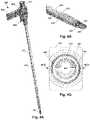
- FIG. 3is a schematic perspective exploded view of one embodiment of a two component lead introducer configured for facilitating implantation of a lead of an electrical stimulation system into a patient, the lead introducer including an integrated needle/sheath and a needle stylet;
- FIG. 4 Ais a schematic perspective view of one embodiment of the integrated needle/sheath of FIG. 3 ;
- FIG. 4 Bis a schematic perspective close-up view of one embodiment of a distal end portion of the integrated needle/sheath of FIG. 4 A ;
- FIG. 4 Cis a schematic perspective close-up view of one embodiment of a distal end portion of the needle of the integrated needle/sheath of FIG. 4 A ;
- FIG. 4 Dis a schematic perspective close-up view of one embodiment of a proximal end portion of the integrated needle/sheath of FIG. 4 A including the hub;
- FIG. 4 Eis a schematic cut-away view of one embodiment of the hub of the integrated needle/sheath of FIG. 4 D ;
- FIG. 4 Fis a close-up schematic view of a portion of the view of FIG. 4 E with the proximal end portions of the needle and splittable sheath attached to the hub;
- FIG. 4 Gis a partial schematic view into the proximal end of the integrated needle/sheath of FIG. 4 A ;
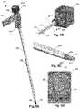
- FIG. 5 Ais a schematic perspective view of one embodiment of the lead introducer of FIG. 3 including integrated needle/sheath and needle stylet;
- FIG. 5 Bis a schematic perspective close-up view of one embodiment of a proximal end portion of the needle style of FIG. 5 A ;
- FIG. 5 Cis a schematic perspective close-up view of one embodiment of a distal end portion of the lead introducer of FIG. 5 A ;
- FIG. 5 Dis a schematic cross-sectional view of one embodiment of the needle stylet of FIGS. 5 A and 5 B ;
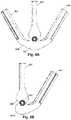
- FIG. 6 Ais a schematic end view of an embodiment of an integrated needle/sheath with an arrangement of three pull-apart tabs
- FIG. 6 Bis a schematic end view of another embodiment of an integrated needle/sheath with an arrangement of two pull-apart tabs;
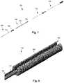
- FIG. 7is a schematic perspective exploded view of one embodiment of a lead introducer configured for facilitating implantation of a lead of an electrical stimulation system into a patient, the lead introducer including a multi-piece insertion needle, a splittable member, and an optional stylet;
- FIG. 8is a schematic perspective view of one embodiment of a proximal end portion of an outer needle of the lead introducer of FIG. 7 ;
- FIG. 9 Ais a schematic perspective view of one embodiment of a lead guide
- FIG. 9 Bis another schematic perspective view of the lead guide of FIG. 9 A from an opposite end;
- FIG. 10 Ais a schematic perspective view of the lead guide of FIG. 9 A disposed on the proximal end portion of the outer needle of FIG. 8 and disposed partially within a hub of the splittable member of FIG. 7 ;
- FIG. 10 Bis a schematic cross-sectional view of the lead guide of FIG. 9 A , proximal end portion of the outer needle of FIG. 8 , and hub of the splittable member of FIG. 7 ;
- FIG. 11is a schematic overview of one embodiment of components of a stimulation system, including an electronic subassembly disposed within a control module, according to the invention.
- the present inventionis directed to the area of implantable stimulation systems and methods of making and using the systems.
- the present inventionis also directed to a lead introducer for facilitating insertion of implantable stimulation leads into patients, as well as methods of making and using the lead introducers and stimulation leads.
- Suitable implantable electrical stimulation systemsinclude, but are not limited to, a least one lead with one or more electrodes disposed along a distal end of the lead and one or more terminals disposed along the one or more proximal ends of the lead. Examples of electrical stimulation systems with leads are found in, for example, U.S. Pat. Nos.
- FIG. 1illustrates schematically one embodiment of an electrical stimulation system 100 .
- the electrical stimulation systemincludes a control module (e.g., a stimulator or pulse generator) 102 and at least one lead 103 coupleable to the control module 102 .
- the lead 103includes one or more lead bodies 106 , an array of electrodes 133 , such as electrode 134 , and an array of terminals (e.g., 210 in FIGS. 2 A and 2 B ) disposed along the one or more lead bodies 106 .
- the leadis isodiametric along a longitudinal length of the lead body 106 .
- FIG. 1illustrates one lead 103 coupled to a control module 102 .
- Other embodimentsmay include two, three, four, or more leads 103 coupled to the control module 102 .
- the lead 103can be coupled to the control module 102 in any suitable manner. In at least some embodiments, the lead 103 couples directly to the control module 102 . In at least some other embodiments, the lead 103 couples to the control module 102 via one or more intermediate devices. For example, in at least some embodiments one or more lead extensions 224 (see e.g., FIG. 2 B ) can be disposed between the lead 103 and the control module 102 to extend the distance between the lead 103 and the control module 102 . Other intermediate devices may be used in addition to, or in lieu of, one or more lead extensions including, for example, a splitter, an adaptor, or the like or combinations thereof. It will be understood that, in the case where the electrical stimulation system 100 includes multiple elongated devices disposed between the lead 103 and the control module 102 , the intermediate devices may be configured into any suitable arrangement.
- the electrical stimulation system 100is shown having a splitter 107 configured and arranged for facilitating coupling of the lead 103 to the control module 102 .
- the splitter 107includes a splitter connector 108 configured to couple to a proximal end of the lead 103 , and one or more splitter tails 109 a and 109 b configured and arranged to couple to the control module 102 (or another splitter, a lead extension, an adaptor, or the like).
- the control module 102typically includes a connector housing 112 and a sealed electronics housing 114 .
- An electronic subassembly 110 and an optional power source 121are disposed in the electronics housing 114 .
- a control module connector 144is disposed in the connector housing 112 .
- the control module connector 144is configured and arranged to make an electrical connection between the lead 103 and the electronic subassembly 110 of the control module 102 .
- the electrical stimulation system or components of the electrical stimulation systemare typically implanted into the body of a patient.
- the electrical stimulation systemcan be used for a variety of applications including, but not limited to, brain stimulation, neural stimulation, spinal cord stimulation, muscle stimulation, and the like.
- the electrodes 134can be formed using any conductive, biocompatible material. Examples of suitable materials include metals, alloys, conductive polymers, conductive carbon, and the like, as well as combinations thereof. In at least some embodiments, one or more of the electrodes 134 are formed from one or more of: platinum, platinum iridium, palladium, palladium rhodium, or titanium.
- the number of electrodes 134 in each array 133may vary. For example, there can be two, four, six, eight, ten, twelve, fourteen, sixteen, or more electrodes 134 . As will be recognized, other numbers of electrodes 134 may also be used.
- the electrodes of the one or more lead bodies 106are typically disposed in, or separated by, a non-conductive, biocompatible material such as, for example, silicone, polyurethane, polyetheretherketone (“PEEK”), epoxy, and the like or combinations thereof.
- the lead bodies 106may be formed in the desired shape by any process including, for example, molding (including injection molding), casting, and the like.
- the non-conductive materialtypically extends from the distal end of the one or more lead bodies 106 to the proximal end of each of the one or more lead bodies 106 .
- Terminalsare typically disposed along the proximal end of the one or more lead bodies 106 of the electrical stimulation system 100 (as well as any splitters, lead extensions, adaptors, or the like) for electrical connection to corresponding connector contacts (e.g., 214 in FIG. 2 A and 240 in FIG. 2 B ).
- the connector contactsare disposed in connectors (e.g., 144 in FIGS. 1 - 2 B ; and 221 in FIG. 2 B ) which, in turn, are disposed on, for example, the control module 102 (or a lead extension, a splitter, an adaptor, or the like).
- Electrode conductive wires, cables, or the likeextend from the terminals to the electrodes 134 .
- one or more electrodes 134are electrically coupled to each terminal.
- each terminalis only connected to one electrode 134 .
- the electrically conductive wiresmay be embedded in the non-conductive material of the lead body 106 or can be disposed in one or more lumens (not shown) extending along the lead body 106 . In some embodiments, there is an individual lumen for each conductor. In other embodiments, two or more conductors extend through a lumen. There may also be one or more lumens (not shown) that open at, or near, the proximal end of the lead body 106 , for example, for inserting a stylet to facilitate placement of the lead body 106 within a body of a patient.
- the one or more lumensmay be flushed continually, or on a regular basis, with saline, epidural fluid, or the like.
- the one or more lumensare permanently or removably sealable at the distal end.
- FIG. 2 Ais a schematic side view of one embodiment of a proximal end of one or more elongated devices 200 configured and arranged for coupling to one embodiment of the control module connector 144 .
- the one or more elongated devicesmay include, for example, the lead body 106 , one or more intermediate devices (e.g., the splitter 107 of FIG. 1 , the lead extension 224 of FIG. 2 B , an adaptor, or the like or combinations thereof), or a combination thereof.
- FIG. 2 Aillustrates two elongated devices 200 coupled to the control module 102 . These two elongated devices 200 can be two tails as illustrated in FIG. 1 or two different leads or any other combination of elongated devices.
- the control module connector 144defines at least one port into which a proximal end of the elongated device 200 can be inserted, as shown by directional arrows 212 a and 212 b .
- the connector housing 112is shown having two ports 204 a and 204 b .
- the connector housing 112can define any suitable number of ports including, for example, one, two, three, four, five, six, seven, eight, or more ports.
- the control module connector 144also includes a plurality of connector contacts, such as connector contact 214 , disposed within each port 204 a and 204 b .
- the connector contacts 214can be aligned with a plurality of terminals 210 disposed along the proximal end(s) of the elongated device(s) 200 to electrically couple the control module 102 to the electrodes ( 134 of FIG. 1 ) disposed at a distal end of the lead 103 .
- Examples of connectors in control modulesare found in, for example, U.S. Pat. Nos. 7,244,150 and 8,224,450, which are incorporated by reference in their entireties.
- FIG. 2 Bis a schematic side view of another embodiment of the electrical stimulation system 100 .
- the electrical stimulation system 100includes a lead extension 224 that is configured and arranged to couple one or more elongated devices 200 (e.g., the lead body 106 , the splitter 107 , an adaptor, another lead extension, or the like or combinations thereof) to the control module 102 .
- the lead extension 224is shown coupled to a single port 204 defined in the control module connector 144 .
- the lead extension 224is shown configured and arranged to couple to a single elongated device 200 .
- the lead extension 224is configured and arranged to couple to multiple ports 204 defined in the control module connector 144 , or to receive multiple elongated devices 200 , or both.
- a lead extension connector 221is disposed on the lead extension 224 .
- the lead extension connector 221is shown disposed at a distal end 226 of the lead extension 224 .
- the lead extension connector 221includes a connector housing 228 .
- the connector housing 228defines at least one port 230 into which terminals 210 of the elongated device 200 can be inserted, as shown by directional arrow 238 .
- the connector housing 228also includes a plurality of connector contacts, such as connector contact 240 .
- the connector contacts 240 disposed in the connector housing 228can be aligned with the terminals 210 of the elongated device 200 to electrically couple the lead extension 224 to the electrodes ( 134 of FIG. 1 ) disposed along the lead ( 103 in FIG. 1 ).
- the proximal end of the lead extension 224is similarly configured and arranged as a proximal end of the lead 103 (or other elongated device 200 ).
- the lead extension 224may include a plurality of electrically conductive wires (not shown) that electrically couple the connector contacts 240 to a proximal end 248 of the lead extension 224 that is opposite to the distal end 226 .
- the conductive wires disposed in the lead extension 224can be electrically coupled to a plurality of terminals (not shown) disposed along the proximal end 248 of the lead extension 224 .
- the proximal end 248 of the lead extension 224is configured and arranged for insertion into a connector disposed in another lead extension (or another intermediate device). In other embodiments (and as shown in FIG. 2 B ), the proximal end 248 of the lead extension 224 is configured and arranged for insertion into the control module connector 144 .
- the stimulation electrodestake the form of segmented electrodes that extend only partially around the perimeter (for example, the circumference) of the lead. These segmented electrodes can be provided in sets of electrodes, with each set having electrodes circumferentially distributed about the lead at a particular longitudinal position.
- a practitionermay determine the position of the target neurons using recording electrode(s) and then position the stimulation electrode(s) accordingly.
- the same electrodescan be used for both recording and stimulation.
- separate leadscan be used; one with recording electrodes which identify target neurons, and a second lead with stimulation electrodes that replaces the first after target neuron identification.
- the same leadmay include both recording electrodes and stimulation electrodes or electrodes may be used for both recording and stimulation.
- the electrodes 134are shown as including both ring electrodes 120 and segmented electrodes 122 . In some embodiments, the electrodes 134 are all segmented.
- the segmented electrodes 122 of FIG. 1are in sets of three (one of which is not visible in FIG. 1 ), where the three segmented electrodes of a particular set are electrically isolated from one another and are circumferentially offset along the lead 1-3. Any suitable number of segmented electrodes can be formed into a set including, for example, two, three, four, or more segmented electrodes.
- the lead 103 of FIG. 1has thirty segmented electrodes 122 (ten sets of three electrodes each) and two ring electrodes 120 for a total of 32 electrodes 134 .
- Segmented electrodescan be used to direct stimulus current to one side, or even a portion of one side, of the lead.
- current steeringcan be achieved to more precisely deliver the stimulus to a position around an axis of the lead (i.e., radial positioning around the axis of the lead).
- Segmented electrodesmay provide for superior current steering than ring electrodes because target structures in deep brain stimulation are not typically symmetric about the axis of the distal electrode array. Instead, a target may be located on one side of a plane running through the axis of the lead.
- current steeringcan be performed not only along a length of the lead but also around a perimeter of the lead. This provides precise three-dimensional targeting and delivery of the current stimulus to neural target tissue, while potentially avoiding stimulation of other tissue.
- Examples of leads with segmented electrodesinclude U.S. Patent Application Publications Nos. 2010/0268298; 2011/0005069; 2011/0078900; 2011/0130803; 2011/0130816; 2011/0130817; 2011/0130818; 2011/0078900; 2011/0238129; 2011/0313500; 2012/0016378; 2012/0046710; 2012/0071949; 2012/0165911; 2012/0197375; 2012/0203316; 2012/0203320; 2012/0203321; 2013/0197602; 2013/0261684; 2013/0325091; 2013/0317587; 2014/0039587; 2014/0353001; 2014/0358209; 2014/0358210; 2015/0018915; 2015/0021817; 2015/0045864; 2015/0021817; 2015/0066120; 2013/0197424; 2015/0151113; 2014/0358207; and U.S.
- a leadmay also include a tip electrode and examples of leads with tip electrodes include at least some of the previously cited references, as well as U.S. Patent Application Publications Nos. 2014/0296953 and 2014/0343647, all of which are incorporated herein by reference in their entireties.
- a lead with segmented electrodesmay be a directional lead that can provide stimulation in a particular direction using the segmented electrodes.
- Conventional percutaneous implantation techniquesoften include inserting a lead introducer, such as an epidural needle, into a patient.
- a leadis then inserted into the lead introducer and the lead introducer is positioned at a target stimulation location.
- the lead introduceris removed from the patient, leaving the lead in place.
- the lead introduceris removed from the patient by sliding the lead introducer off the proximal end of the lead. This action, however, may result in movement of the lead so that it is no longer positioned at the desired stimulation location.
- lateral release lead introducerthat includes a multi-piece insertion needle that enables a lead to be laterally separated from the multi-piece insertion needle instead of sliding the needle off the end of the lead.
- Examples of lateral release lead introducersare found in, for example, U.S. Patent Application Publication Nos. 2011/0224680, 2014/0039586, 2014/0276927, 2015/0073431, 2015/0073432, and 2016/0317800, all of which are incorporated herein by reference in their entireties.
- These lateral release lead introducersinclude an outer needle, an inner needle, a splittable member, and a stylet.
- Lateral release lead introducersintroduce more complexity than the conventional lead introducer discussed above which only uses one or two components (e.g., an epidural needle and an optional stylet). Lateral release lead introducers can be particularly useful for implanting leads have multiple tails, such as the lead 103 illustrated in FIG. 3 , or other non-isodiametric arrangements along the lead.
- FIG. 3illustrates a two component lateral release lead introducer 430 having an integrated needle/sheath 440 and a needle stylet 470 .
- the needle stylet 470is inserted into the integrated needle/sheath 440 and the combination is inserted into the patient.
- the needle stylet 470is removed from the integrated needle/sheath 440 and a lead 103 is inserted into the integrated needle/sheath 440 for delivery and placement of the lead at the implant site.
- FIGS. 4 A to 4 Fillustrate an integrated needle/sheath 440 which includes a needle 442 , a splittable sheath 450 , and a hub 460 .
- the needle 442 of the integrated needle/sheath 440includes a proximal end portion 441 ( FIG. 4 F ), a distal end portion 443 ( FIG. 4 C ), and an open channel 444 ( FIG. 4 C ) that extends along the longitudinal length of the needle.
- the needle stylet 470 and the lead 103are sequentially received in the open channel 444 during the implantation procedure.
- the needle 442further includes a slot 446 along the length of the needle.
- the needle 442has a body 448 that defines two opposing ends 449 a , 449 b that are separated from each other along the length of the body to define the slot 446 .
- This slot 446allows for lateral separation of the lead 103 from the needle 442 by laterally passing the lead, initially residing in the open channel 444 , through the slot.
- the slot 446is at least as wide as the diameter of the lead 103 .
- the lead 103has a diameter that is larger than the slot 446 of the needle 442 .
- the body of the lead 103may be formed from a deformable material and the lead is removable from the open channel 444 by applying a lateral force to at least one of the lead 103 or the needle 442 to deform the lead enough to enable the lead to be passed laterally out through the slot 446 in the needle 442 .
- the needle 442can be made from any suitable material including, but not limited to, stainless steel or other metal.
- the distal end portion 443 of the needle 442may have a slanted face 445 with a sharpened end 447 suitable for piercing patient tissue during insertion of the lead introducer 430 into the patient. At least the sharpened end 447 of the needle 442 , and preferably the slanted face, extends distally beyond the distal end of the splittable sheath 450 , as illustrated in FIG. 4 B .
- the distal end portion 443 of the needle 442may have a Tuohy tip or blunt epidural tip.
- An optional bendcan be provided along the distal end portion of the needle 442 such as, for example, the bend disclosed in U.S. Patent Application Publication No. 2016/0317800, incorporated herein by reference in its entirety.
- the splittable sheath 450is arranged to split along the longitudinal length of the splittable sheath 450 into two portions.
- the splittable sheath 450includes one or more perforated (or scored, weakened, thinned, or the like) regions 452 extending along at least a portion of the longitudinal length of the splittable sheath 450 , as illustrated in FIGS. 4 A and 4 B .
- the splittable sheath 450can be pre-split, perforated, scored, weakened, or thinned only within, or adjacent to, the hub 460 and have no further perforations or the like along the length of the splittable sheath.
- the splittable sheathcan be made of any suitable material including, but not limited to, polymer materials such as high density polyethylene (HDPE), polytetrafluoroethylene (PTFE), or the like.
- polymer materialssuch as high density polyethylene (HDPE), polytetrafluoroethylene (PTFE), or the like.
- HDPEhigh density polyethylene
- PTFEpolytetrafluoroethylene
- materials such as PTFEwhen extruded, can split easily and reliably in the direction of the extrusion without having to pre-score or perforate.
- the splittable sheath 450is arranged to split along the longitudinal axis into a first portion 454 and a second portion 456 .
- the integrated needle/sheath 440 the needle 442remains attached to the first portion 454 of the splittable sheath 450 when it is split.
- the second portion 456 of the splittable sheath 450separates from the needle 442 and also exposes the slot 446 in the needle to allow the lead 103 to be removed from the open channel 444 in the needle.
- the hub 460includes a body 462 and at least two pull-apart tabs 464 , 466 that extend away from the body 462 of the hub 460 .
- the two pull-apart tabs 464 , 466can be used to separate the splittable sheath 450 (and, at least in some embodiments, the hub 460 ) into two portions by pulling the two pull-apart tabs away from each other.
- the separation processmay also include first squeezing the two pull-apart tabs 464 , 466 together to initiate separation of one or both of the hub 460 and splittable sheath 450 and then pulling the two pull-apart tabs 464 , 466 away from each other to complete the separation.
- an angle 468 between the two pull-apart tabs 464 , 466is less than 180, 120, 90, or 60 degrees.
- the pull-apart tabscan be 180 degrees apart, as disclosed in U.S. Patent Application Publication Nos. 2011/0224680, 2014/0039586, 2014/0276927, 2015/0073431, and 2015/0073432, all of which are incorporated herein by reference in their entireties.
- the pull-apart tabsmay extend proximally parallel (or at an acute angle no more than 89, 80, 75, 60, or 45 degrees) to the longitudinal axis of the splittable sheath 450 as disclosed in U.S. Patent Application Publication No. 2016/0317800, incorporated herein by reference in its entirety.
- the body 462 of the hub 460includes, at the proximal end of the body, a small-bore connector 461 , such as a Luer fitting, which may be used for coupling with other devices.
- the body 462 (and the small-bore connector 461 , if included)can include one or two slits or weakened regions 463 a , 463 b between the pull-apart tabs 464 , 466 to facilitate separation of the body (and small-bore connector, if included) into two portions when the splittable sheath 462 is split and separated into two regions using the two pull-apart tabs 464 , 466 , as described above.
- the small-bore connector 461can facilitate a loss of resistance (LOR) procedure. Because entry into the epidural space is a delicate procedure requiring greater precision than may be obtained via fluoroscopy, LOR is used to insert the tip of the needle 442 just barely into the epidural space. The clinician initially inserts the fully-assembled lead introducer 430 into the patient until the tip is near the epidural space. Then, the needle stylet 470 is removed and a syringe filled with air or saline is connected to the needle 442 through the small-bore connector 461 . The clinician slowly advances the needle 442 while applying pressure to the syringe plunger.
- LORloss of resistance
- the tissueoccludes the needle tip, preventing fluid from escaping, and providing resistance to the syringe plunger. Once the tip of the needle 442 breaches the epidural space, the fluid can escape the needle tip and the syringe plunger is easily depressed indicating to the clinician that the needle tip has entered the epidural space.
- the hub 460is separable into two parts 465 a , 465 b using the at least two pull-apart tabs 464 , 466 . Separating the hub 460 can also lead to separation of the splittable sheath 450 into the two portions 454 , 456 .
- the first portion 465 a of the hub 460is attached to the needle 442 using any suitable method or material.
- the first portion 465 a of the hub 460can be attached to the needle 442 by adhesive or by overmolding of the first portion 465 a of the hub 460 onto the needle 442 or by any other suitable attachment method.
- the first portion 465 a of the hub 460is also attached to the first portion 454 of the splittable sheath 450 so that, when separation of the two portions 465 a , 465 b of the hub 460 occurs, the first portions 465 a of the hub 460 , first portion 454 of the splittable sheath 450 , and needle 442 remain fixed together.
- the second portion 465 b of the hub 460 and the second portion 456 of the splittable sheath 450remain fixed together.
- the first portion 454 of the splittable sheath 450may also be attached to the needle 442 by adhesive or by heat shrinking or melting the first portion 454 of the splittable sheath 450 onto the needle 442 or any other suitable method.
- the attachment of the first portion 454 of the splittable sheath 450 to the needle 442is sufficient so that the splittable sheath 450 remains attached to the needle 442 during insertion of the lead introducer 430 into the patient.
- the attachment of the first portion 454 of the splittable sheath 450 to the needle 442may allow some disengagement of the first portion 454 from the needle 442 after splitting of the hub 460 and splittable sheath 450 .
- FIG. 4 Eis a cutaway view of a portion of the hub 460 illustrating features within the hub and FIG. 4 F is an expanded portion of hub 460 illustrating the attachment of the proximal end 441 of the needle 442 and proximal end 457 of the splittable sheath 450 inside the hub.
- the needle 442 and splittable sheath 450are attached to the hub 460 using any suitable method or material.
- the attachment of the hub 460 to proximal end 441 of the needle 442 and proximal end 457 of the splittable sheath 450should be sufficient so that the hub 460 remains attached to the proximal end 441 of the needle 442 and proximal end 457 of the splittable sheath 450 when the splittable sheath 450 and hub 460 are split and separated.
- the hub 460defines a hub lumen 459 that is in communication with the open channel 444 of the needle 442 and through which the needle stylet 470 and lead 103 can be inserted into the open channel of the needle.
- the hub 460defines a taper 467 of the hub lumen between the small-bore connector 451 and the region in which the proximal end 441 of the needle 442 is positioned to facilitate a smooth insertion of the needle stylet 470 and lead 103 into the open channel 444 of the needle 442 .
- the hub 460further defines a first shoulder 469 a against which the proximal end 441 of the needle 442 is positioned and a second should 469 b against which the proximal end 457 of the splittable sheath 450 is positioned.
- the hub 460further defines one or two gaps 468 in the first and second shoulders 469 a , 469 b to facilitate reliable splitting of the hub along the intended lines demarcated by the gaps and which may be further demarcated by corresponding slits or weakened regions 463 a , 463 b ( FIG. 4 D ) on the exterior of the hub.
- 4 Gis a view into the hub lumen 459 from the proximal end of the hub 460 illustrating the small-bore connector 451 , taper 467 , and gaps 468 , as well as the slits or weakened regions 463 a , 463 b in the small-bore connector.
- the hub 460further defines a notch 455 which receives a portion of the needle stylet 470 , as described in more detail below, and which is aligned with the slot 446 of the needle 442 .
- FIG. 5 Aillustrates the lead introducer 430 with the needle stylet 470 inserted into the integrated needle/sheath 440 .
- the needle stylet 470may be inserted into the integrated needle/sheath 440 to improve stiffness and prevent or reduce tissue coring during insertion of the lead introducer 430 into the tissue of the patient.
- FIGS. 5 B to 5 Dillustrate features of the needle stylet.
- the stylet body 470is arranged to fit within the open channel 444 of the needle 442 .
- FIG. 5 Billustrates a stylet body 472 (which may also form a needle) and handle 474 of the needle stylet 470 where the handle is attached to the proximal end of the stylet body.
- the handle 474 of the needle styletis arranged to couple to the small-bore connector 451 of the hub 460 .
- FIG. 5 Cillustrates the distal end portion 476 of the stylet body 472 extending out of the splittable sheath 450 and disposed in the distal end of the needle 442 .
- the distal end portion 476 of the stylet body 472may have a slanted face with a sharpened end to facilitate insertion of the lead introducer into the tissue of the patient.
- the distal end portion 476 of the stylet body 472may have a Tuohy tip or blunt epidural tip.
- the needle stylet 470is shaped such that the needle stylet 470 does not separate laterally from the open channel 444 when the needle stylet 470 is received by the needle 442 .
- FIG. 5 Dis a partial cross-sectional view of a portion of the handle 474 and the stylet body 472 to illustrate that, at least in some embodiments, the stylet body 472 includes a cylindrical portion 471 and a stiffening portion 473 that extends from the cylindrical portion 471 .
- the stiffening portion 473is sized and arranged to fit into the slot 446 ( FIG. 4 C ) of the needle 442 when the needle stylet 470 is inserted into the integrated needle/sheath 440 .
- the stiffening portion 473may also be sized and arranged to fit into the notch 455 ( FIG. 4 G ) in the hub 460 .
- the stiffening portion 473may run an entire length of the body 472 (or at least until the distal end portion 476 ) or may terminate at any point along the length of the body 472 . In at least some embodiments, the stiffening portion 473 may terminate distal of the handle 474 .
- FIGS. 6 A and 6 Billustrate two examples of different pull-apart tab arrangements for the lead introducer. It will be recognized that these are simply examples of pull-apart tab arrangements and that any other suitable arrangement of two or more pull-apart tabs can be used.
- the hub 660 of the lead introducerincludes a body 662 and three pull-apart tabs 664 , 665 , 666 .
- the three pull-apart tabs 664 , 665 , 666can be arranged symmetrically with the two outer pull-apart tabs 664 , 666 arranged equidistant from the center pull-apart tab 665 .
- the two outer pull-apart tabs 664 , 666can be arranged with different distances, or at different angles, from the center pull-apart tab 665 .
- the hub 660includes a body 662 and two pull-apart tabs 664 , 666 .
- One pull-apart tab 664includes an extension 664 a that wraps around a portion of the body 662 to form a more lever-like arrangement to facilitate application of torque when separating the hub 660 into two portions.
- FIG. 7is a schematic perspective exploded view of another embodiment of a lead introducer 702 configured and arranged to facilitate implantation of an electrical stimulation system into a patient.
- the lead introducer 702includes a multi-piece insertion needle 708 , a splittable member 750 , and a stylet 770 .
- the multi-piece insertion needle 708includes an inner needle 710 that is insertable into an outer needle 730 . Additional examples of this lead introducer, as well as further details about embodiments of this lead introducer, are disclosed in U.S. Patent Application Publication Nos. 2011/0224680, 2014/0039586, 2014/0276927, 2015/0073431, 2015/0073432, and 2016/0317800, all of which are incorporated by reference in their entirety.
- the outer needle 730is disposed within the splittable sheath 750 .
- the outer needleincludes a needle hub 740 and a body 732 .
- the splittable sheath 750includes a sheath body 752 and sheath hub 760 .
- FIG. 8illustrates a proximal portion of the outer needle 730 including the needle hub 740 .
- the body 732 and needle hub 740 of outer needle 742define an open channel 744 and a slot 746 .
- FIGS. 9 A and 9 Billustrate a lead guide 990 that can be inserted into the needle hub 740 of the outer needle 742 , as illustrated in FIG. 10 A , to prevent the lead 103 from popping out of the slot 746 .
- the lead guide 990includes a barrel 992 , a stop ring 994 , an extension 996 that extends distally from the stop ring and barrel, and a guide slot 998 .
- the barrel 992slides onto the needle hub 740 , as illustrated in FIG. 10 A , to cover the slot 746 of the needle hub.
- the lead guide 990can be pushed into the sheath hub 760 and may be press fit into the sheath hub to prevent or reduce slippage.
- the stop ring 994is provided to stop the lead guide 990 from sliding too far along the needle hub 740 and, at least in some embodiments, is stopped by the sheath hub 760 , as illustrated in FIG. 10 B .
- the extension 996may also act as a stop against a portion 762 of the sheath hub 760 and may also orient the lead guide 990 relative to the needle hub 740 or sheath hub 760 .
- FIG. 11is a schematic overview of one embodiment of components of an electrical stimulation system 1100 including an electronic subassembly 1110 disposed within a control module. It will be understood that the electrical stimulation system can include more, fewer, or different components and can have a variety of different configurations including those configurations disclosed in the stimulator references cited herein.
- Some of the components (for example, power source 1112 , antenna 1118 , receiver 1102 , and processor 1104 ) of the electrical stimulation systemcan be positioned on one or more circuit boards or similar carriers within a sealed housing of an implantable pulse generator, if desired.
- Any power source 1112can be used including, for example, a battery such as a primary battery or a rechargeable battery.
- Examples of other power sourcesinclude super capacitors, nuclear or atomic batteries, mechanical resonators, infrared collectors, thermally-powered energy sources, flexural powered energy sources, bioenergy power sources, fuel cells, bioelectric cells, osmotic pressure pumps, and the like including the power sources described in U.S. Pat. No. 11,437,193, incorporated herein by reference in its entirety.
- powercan be supplied by an external power source through inductive coupling via the optional antenna 1118 or a secondary antenna.
- the external power sourcecan be in a device that is mounted on the skin of the user or in a unit that is provided near the user on a permanent or periodic basis.
- the batterymay be recharged using the optional antenna 1118 , if desired. Power can be provided to the battery for recharging by inductively coupling the battery through the antenna to a recharging unit 1116 external to the user. Examples of such arrangements can be found in the references identified above.
- electrical currentis emitted by the electrodes 134 on the lead body to stimulate nerve fibers, muscle fibers, or other body tissues near the electrical stimulation system.
- a processor 1104is generally included to control the timing and electrical characteristics of the electrical stimulation system. For example, the processor 1104 can, if desired, control one or more of the timing, frequency, amplitude, width, and waveform of the pulses. In addition, the processor 1104 can select which electrodes can be used to provide stimulation, if desired. In some embodiments, the processor 1104 may select which electrode(s) are cathodes and which electrode(s) are anodes. In some embodiments, the processor 1104 may be used to identify which electrodes provide the most useful stimulation of the desired tissue.
- Any processorcan be used and can be as simple as an electronic device that, for example, produces pulses at a regular interval or the processor can be capable of receiving and interpreting instructions from an external programming unit 1108 that, for example, allows modification of pulse characteristics.
- the processor 1104is coupled to a receiver 1102 which, in turn, is coupled to the optional antenna 1118 . This allows the processor 1104 to receive instructions from an external source to, for example, direct the pulse characteristics and the selection of electrodes, if desired.
- the antenna 1118is capable of receiving signals (e.g., RF signals) from an external telemetry unit 1106 which is programmed by a programming unit 1108 .
- the programming unit 1108can be external to, or part of, the telemetry unit 1106 .
- the telemetry unit 1106can be a device that is worn on the skin of the user or can be carried by the user and can have a form similar to a pager, cellular phone, or remote control, if desired.
- the telemetry unit 1106may not be worn or carried by the user but may only be available at a home station or at a clinician's office.
- the programming unit 1108can be any unit that can provide information to the telemetry unit 1106 for transmission to the electrical stimulation system 1100 .
- the programming unit 1108can be part of the telemetry unit 1106 or can provide signals or information to the telemetry unit 1106 via a wireless or wired connection.
- One example of a suitable programming unitis a computer operated by the user or clinician to send signals to the telemetry unit 1106 .
- the signals sent to the processor 1104 via the antenna 1118 and receiver 1102can be used to modify or otherwise direct the operation of the electrical stimulation system.
- the signalsmay be used to modify the pulses of the electrical stimulation system such as modifying one or more of pulse width, pulse frequency, pulse waveform, and pulse amplitude.
- the signalsmay also direct the electrical stimulation system 1100 to cease operation, to start operation, to start charging the battery, or to stop charging the battery.
- the stimulation systemdoes not include an antenna 1118 or receiver 1102 and the processor 1104 operates as programmed.
- the electrical stimulation system 1100may include a transmitter (not shown) coupled to the processor 1104 and the antenna 1118 for transmitting signals back to the telemetry unit 1106 or another unit capable of receiving the signals.
- the electrical stimulation system 1100may transmit signals indicating whether the electrical stimulation system 1100 is operating properly or not or indicating when the battery needs to be charged or the level of charge remaining in the battery.
- the processor 1104may also be capable of transmitting information about the pulse characteristics so that a user or clinician can determine or verify the characteristics.
Landscapes
- Health & Medical Sciences (AREA)
- Life Sciences & Earth Sciences (AREA)
- Engineering & Computer Science (AREA)
- Biomedical Technology (AREA)
- Nuclear Medicine, Radiotherapy & Molecular Imaging (AREA)
- Animal Behavior & Ethology (AREA)
- General Health & Medical Sciences (AREA)
- Public Health (AREA)
- Veterinary Medicine (AREA)
- Radiology & Medical Imaging (AREA)
- Neurology (AREA)
- Neurosurgery (AREA)
- Surgery (AREA)
- Heart & Thoracic Surgery (AREA)
- Pathology (AREA)
- Medical Informatics (AREA)
- Molecular Biology (AREA)
- Cardiology (AREA)
- Orthopedic Medicine & Surgery (AREA)
- Pain & Pain Management (AREA)
- Electrotherapy Devices (AREA)
- Infusion, Injection, And Reservoir Apparatuses (AREA)
Abstract
Description
Claims (20)
Priority Applications (1)
| Application Number | Priority Date | Filing Date | Title |
|---|---|---|---|
| US16/791,781US11529510B2 (en) | 2019-02-19 | 2020-02-14 | Lead introducers and systems and methods including the lead introducers |
Applications Claiming Priority (2)
| Application Number | Priority Date | Filing Date | Title |
|---|---|---|---|
| US201962807351P | 2019-02-19 | 2019-02-19 | |
| US16/791,781US11529510B2 (en) | 2019-02-19 | 2020-02-14 | Lead introducers and systems and methods including the lead introducers |
Publications (2)
| Publication Number | Publication Date |
|---|---|
| US20200261714A1 US20200261714A1 (en) | 2020-08-20 |
| US11529510B2true US11529510B2 (en) | 2022-12-20 |
Family
ID=69846555
Family Applications (1)
| Application Number | Title | Priority Date | Filing Date |
|---|---|---|---|
| US16/791,781Active2041-02-06US11529510B2 (en) | 2019-02-19 | 2020-02-14 | Lead introducers and systems and methods including the lead introducers |
Country Status (5)
| Country | Link |
|---|---|
| US (1) | US11529510B2 (en) |
| EP (1) | EP3883644A2 (en) |
| CN (1) | CN113453749B (en) |
| AU (1) | AU2020226356B2 (en) |
| WO (1) | WO2020172071A2 (en) |
Cited By (6)
| Publication number | Priority date | Publication date | Assignee | Title |
|---|---|---|---|---|
| USD1021113S1 (en)* | 2018-06-29 | 2024-04-02 | Spr Therapeutics, Inc. | Introducer needle of a lead placement tool |
| WO2025075826A1 (en) | 2023-10-02 | 2025-04-10 | Boston Scientific Neuromodulation Corporation | Lead introducers and systems including the lead introducers |
| US12357792B2 (en) | 2019-01-04 | 2025-07-15 | Shifamed Holdings, Llc | Internal recharging systems and methods of use |
| US12403296B2 (en) | 2018-05-30 | 2025-09-02 | Kardion Gmbh | Apparatus for anchoring a ventricular assist system in a blood vessel, operating method, production method for producing an apparatus and ventricular assist system |
| US12403315B2 (en) | 2021-04-27 | 2025-09-02 | Boston Scientific Neuromodulation Corporation | Systems and methods for automated programming of electrical stimulation |
| US12440656B2 (en) | 2021-04-23 | 2025-10-14 | Shifamed Holdings, Llc | Power management for interatrial shunts and associated systems and methods |
Citations (142)
| Publication number | Priority date | Publication date | Assignee | Title |
|---|---|---|---|---|
| US3330278A (en) | 1964-06-22 | 1967-07-11 | Louis S Santomieri | Hypodermic needle for a cannula placement unit |
| US3359978A (en) | 1964-10-26 | 1967-12-26 | Jr Raymond M Smith | Guide needle for flexible catheters |
| US3568660A (en) | 1967-11-20 | 1971-03-09 | Battelle Development Corp | Pacemaker catheter |
| US3677243A (en) | 1971-09-24 | 1972-07-18 | Extracorporeal Med Spec | Separable surgical needle |
| US4166469A (en) | 1977-12-13 | 1979-09-04 | Littleford Philip O | Apparatus and method for inserting an electrode |
| US4355646A (en) | 1980-11-26 | 1982-10-26 | Medtronic, Inc. | Transvenous defibrillating lead |
| US4449973A (en) | 1982-06-26 | 1984-05-22 | Luther Medical Products, Inc. | Small gauge, pre-split cannula and process for manufacture |
| USRE31855E (en) | 1978-12-01 | 1985-03-26 | Cook, Inc. | Tear apart cannula |
| US4512351A (en) | 1982-11-19 | 1985-04-23 | Cordis Corporation | Percutaneous lead introducing system and method |
| US4608986A (en) | 1984-10-01 | 1986-09-02 | Cordis Corporation | Pacing lead with straight wire conductors |
| WO1989000436A1 (en) | 1987-07-13 | 1989-01-26 | Coombs Dennis W | Multi-lumen epidural-spinal needle |
| US5125904A (en) | 1991-07-09 | 1992-06-30 | Lee Hongpyo H | Splittable hemostatic valve and sheath and the method for using the same |
| US5255691A (en) | 1991-11-13 | 1993-10-26 | Medtronic, Inc. | Percutaneous epidural lead introducing system and method |
| US5312355A (en) | 1991-07-09 | 1994-05-17 | H L Medical Inventions, Inc. | Splittable hemostatic valve and sheath and the method for using the same |
| US5320602A (en) | 1993-05-14 | 1994-06-14 | Wilson-Cook Medical, Inc. | Peel-away endoscopic retrograde cholangio pancreatography catheter and a method for using the same |
| US5380290A (en) | 1992-04-16 | 1995-01-10 | Pfizer Hospital Products Group, Inc. | Body access device |
| US5409469A (en) | 1993-11-04 | 1995-04-25 | Medtronic, Inc. | Introducer system having kink resistant splittable sheath |
| US5441504A (en) | 1992-04-09 | 1995-08-15 | Medtronic, Inc. | Splittable lead introducer with mechanical opening valve |
| US5713867A (en) | 1996-04-29 | 1998-02-03 | Medtronic, Inc. | Introducer system having kink resistant splittable sheath |
| US5741233A (en) | 1995-10-20 | 1998-04-21 | Tfx Medical, Incorporated | Introducer device and methods of use thereof |
| US5752937A (en) | 1997-04-30 | 1998-05-19 | Medtronic Inc. | Reinforced splittable medical introducer cannula |
| US5755693A (en) | 1992-09-09 | 1998-05-26 | Menlo Care, Inc. | Bloodless splittable introducer |
| US5931863A (en) | 1997-12-22 | 1999-08-03 | Procath Corporation | Electrophysiology catheter |
| US6080141A (en) | 1997-12-22 | 2000-06-27 | Becton, Dickinson And Company | Splittable tubular medical device and method for manufacture |
| US6181969B1 (en) | 1998-06-26 | 2001-01-30 | Advanced Bionics Corporation | Programmable current output stimulus stage for implantable device |
| US6251119B1 (en) | 1998-08-07 | 2001-06-26 | Embol-X, Inc. | Direct stick tear-away introducer and methods of use |
| US6358460B1 (en) | 1999-12-23 | 2002-03-19 | Tfx Medical Incorporation | Method for tip forming peelable PTFE tubing |
| US20020111617A1 (en) | 2001-02-09 | 2002-08-15 | Cosman Eric R. | Adjustable trans-urethral radio-frequency ablation |
| US6454744B1 (en) | 1999-12-23 | 2002-09-24 | Tfx Medical, Inc. | Peelable PTFE sheaths and methods for manufacture of same |
| US6494860B2 (en) | 2001-02-08 | 2002-12-17 | Oscor Inc. | Introducer with multiple sheaths and method of use therefor |
| US6516227B1 (en) | 1999-07-27 | 2003-02-04 | Advanced Bionics Corporation | Rechargeable spinal cord stimulator system |
| WO2003011361A2 (en) | 2001-08-02 | 2003-02-13 | Teodulo Aves | Medical needle |
| US6582390B1 (en) | 2000-11-08 | 2003-06-24 | Endovascular Technologies, Inc. | Dual lumen peel-away sheath introducer |
| US6609029B1 (en) | 2000-02-04 | 2003-08-19 | Advanced Bionics Corporation | Clip lock mechanism for retaining lead |
| US6609032B1 (en) | 1999-01-07 | 2003-08-19 | Advanced Bionics Corporation | Fitting process for a neural stimulation system |
| US6641564B1 (en) | 2000-11-06 | 2003-11-04 | Medamicus, Inc. | Safety introducer apparatus and method therefor |
| US6645178B1 (en) | 1997-04-21 | 2003-11-11 | Larry G. Junker | Apparatus for inserting medical device |
| US6712791B2 (en) | 1999-12-30 | 2004-03-30 | Cook Vascular Incorporated | Splittable medical valve |
| US6741892B1 (en) | 2000-03-10 | 2004-05-25 | Advanced Bionics Corporation | Movable contact locking mechanism for spinal cord stimulator lead connector |
| US6749600B1 (en) | 2000-11-15 | 2004-06-15 | Impulse Dynamics N.V. | Braided splittable catheter sheath |
| US6758854B1 (en) | 1997-05-09 | 2004-07-06 | St. Jude Medical | Splittable occlusion balloon sheath and process of use |
| US20050021119A1 (en) | 2003-04-25 | 2005-01-27 | Medtronic, Inc. | Implantable medical lead and system, and method of use thereof |
| US20050055027A1 (en) | 2002-02-25 | 2005-03-10 | Yeung Jeffrey Eric | Expandable fastener with compressive grips |
| US6869416B2 (en) | 1996-09-13 | 2005-03-22 | Scimed Life Systems, Inc. | Multi-size convertible catheter |
| US20050107861A1 (en) | 2003-10-03 | 2005-05-19 | Harris Charmaine K. | Kit for implantation of therapy elements |
| US20050113860A1 (en) | 2003-07-11 | 2005-05-26 | Yaron Keidar | Trans-septal sheath with splitting dilating needle and method for its use |
| US6939327B2 (en) | 2002-05-07 | 2005-09-06 | Cardiac Pacemakers, Inc. | Peel-away sheath |
| US7001396B2 (en) | 2003-03-26 | 2006-02-21 | Enpath Medical, Inc. | Safety introducer assembly and method |
| US7101353B2 (en) | 1999-12-30 | 2006-09-05 | Cook Vascular Incorporated | Splittable medical valve |
| US7192433B2 (en) | 2002-03-15 | 2007-03-20 | Oscor Inc. | Locking vascular introducer assembly with adjustable hemostatic seal |
| US20070150036A1 (en) | 2005-12-27 | 2007-06-28 | Advanced Bionics Corporation | Stimulator leads and methods for lead fabrication |
| US7244150B1 (en) | 2006-01-09 | 2007-07-17 | Advanced Bionics Corporation | Connector and methods of fabrication |
| US7359755B2 (en) | 2003-08-08 | 2008-04-15 | Advanced Neuromodulation Systems, Inc. | Method and apparatus for implanting an electrical stimulation lead using a flexible introducer |
| US7437193B2 (en) | 2002-06-28 | 2008-10-14 | Boston Scientific Neuromodulation Corporation | Microstimulator employing improved recharging reporting and telemetry techniques |
| US7450997B1 (en) | 2000-12-29 | 2008-11-11 | Boston Scientific Neuromodulation Corporation | Method of implanting a lead for brain stimulation |
| US20080300538A1 (en) | 2002-08-29 | 2008-12-04 | Medical Components, Inc. | Releasably Locking Dilator and Sheath Assembly |
| EP2008686A1 (en) | 2007-06-27 | 2008-12-31 | Quan Emerteq Corporation | Percutaneous electrode array and system |
| US7524305B2 (en) | 2004-09-07 | 2009-04-28 | B. Braun Medical, Inc. | Peel-away introducer and method for making the same |
| US20090187222A1 (en) | 2008-01-23 | 2009-07-23 | Boston Scientific Neuromodulation Corporation | Steerable stylet handle assembly |
| US20090248111A1 (en) | 2008-03-31 | 2009-10-01 | Boston Scientific Neuromodulation Corporation | Implantable multi-lead electric stimulation system and methods of making and using |
| US20090254019A1 (en) | 2006-06-12 | 2009-10-08 | Karen Julie Gehl | Electrode introducer device |
| US20090259283A1 (en) | 2008-04-09 | 2009-10-15 | Brandt Michael S | Sheathed lead for pacing or defibrillation |
| US20090276021A1 (en) | 2008-04-30 | 2009-11-05 | Boston Scientific Neuromodulation Corporation | Electrodes for stimulation leads and methods of manufacture and use |
| US7672734B2 (en) | 2005-12-27 | 2010-03-02 | Boston Scientific Neuromodulation Corporation | Non-linear electrode array |
| US20100076535A1 (en) | 2008-09-25 | 2010-03-25 | Boston Scientific Neuromodulation Corporation | Leads with non-circular-shaped distal ends for brain stimulation systems and methods of making and using |
| US7744571B2 (en) | 2007-06-22 | 2010-06-29 | Medical Components, Inc. | Tearaway sheath assembly with hemostasis valve |
| US7761165B1 (en) | 2005-09-29 | 2010-07-20 | Boston Scientific Neuromodulation Corporation | Implantable stimulator with integrated plastic housing/metal contacts and manufacture and use |
| US7783359B2 (en) | 2005-01-05 | 2010-08-24 | Boston Scientific Neuromodulation Corporation | Devices and methods using an implantable pulse generator for brain stimulation |
| US7809446B2 (en) | 2005-01-05 | 2010-10-05 | Boston Scientific Neuromodulation Corporation | Devices and methods for brain stimulation |
| US20100268298A1 (en) | 2009-04-16 | 2010-10-21 | Boston Scientific Neuromodulation Corporation | Deep brain stimulation current steering with split electrodes |
| US20110005069A1 (en) | 2009-07-07 | 2011-01-13 | Boston Scientific Neuromodulation Corporation | Systems and leads with a radially segmented electrode array and methods of manufacture |
| US20110054402A1 (en) | 2009-08-27 | 2011-03-03 | Terumo Kabushiki Kaisha | Indwelling needle assembly and method of using the same |
| US7909798B2 (en) | 2007-07-25 | 2011-03-22 | Oscor Inc. | Peel-away introducer sheath having pitched peel lines and method of making same |
| US20110078900A1 (en) | 2009-07-07 | 2011-04-07 | Boston Scientific Neuromodulation Corporation | Methods for making leads with radially-aligned segmented electrodes for electrical stimulation systems |
| US7941227B2 (en) | 2008-09-03 | 2011-05-10 | Boston Scientific Neuromodulation Corporation | Implantable electric stimulation system and methods of making and using |
| US7938806B2 (en) | 2008-03-14 | 2011-05-10 | Medical Components, Inc. | Tearaway introducer sheath with hemostasis valve |
| US7949395B2 (en) | 1999-10-01 | 2011-05-24 | Boston Scientific Neuromodulation Corporation | Implantable microdevice with extended lead and remote electrode |
| US20110130818A1 (en) | 2009-11-30 | 2011-06-02 | Boston Scientific Neuromodulation Corporation | Electrode array having concentric split ring electrodes and methods of making the same |
| US20110130817A1 (en) | 2009-11-30 | 2011-06-02 | Boston Scientific Neuromodulation Corporation | Electrode array having a rail system and methods of manufacturing the same |
| US20110130816A1 (en) | 2009-11-30 | 2011-06-02 | Boston Scientific Neuromodulation Corporation | Electrode array with electrodes having cutout portions and methods of making the same |
| US20110130803A1 (en) | 2009-11-30 | 2011-06-02 | Boston Scientific Neuromodulation Corporation | Electrode array having concentric windowed cylinder electrodes and methods of making the same |
| US7974706B2 (en) | 2006-03-30 | 2011-07-05 | Boston Scientific Neuromodulation Corporation | Electrode contact configurations for cuff leads |
| US7985232B2 (en) | 2003-07-08 | 2011-07-26 | St. Jude Medical, Atrial Fibrillation Division, Inc. | Detachable hemostasis valve and splittable sheath assembly |
| US7993305B2 (en) | 2008-10-22 | 2011-08-09 | Greatbatch Ltd. | Splittable valved introducer apparatus |
| US20110218549A1 (en) | 2010-03-05 | 2011-09-08 | Boston Scientific Neuromodulation Corporation | Systems and methods for making and using a trial stimulation system having an electrical connector disposed on a trial stimulation lead |
| US20110224680A1 (en) | 2010-03-10 | 2011-09-15 | Boston Scientific Neuromodulation Corporation | System and method for making and using a lead introducer for an implantable electrical stimulation system |
| US20110224681A1 (en) | 2010-03-15 | 2011-09-15 | Boston Scientific Neuromodulation Corporation | System and method for making and using a splitable lead introducer for an implantable electrical stimulation system |
| US20110230893A1 (en) | 2010-03-19 | 2011-09-22 | Boston Scientific Neuromodulation Corporation | Systems and methods for making and using electrical stimulation systems having multi-lead-element lead bodies |
| US20110238129A1 (en) | 2010-03-23 | 2011-09-29 | Boston Scientific Neuromodulation Corporation | Helical radial spacing of contacts on a cylindrical lead |
| US8043263B2 (en) | 2008-10-09 | 2011-10-25 | Pacesetter, Inc. | Slittable delivery device assembly for the delivery of a cardiac surgical device |
| US20110313500A1 (en) | 2010-06-18 | 2011-12-22 | Boston Scientific Neuromodulation Corporation | Electrode array having embedded electrodes and methods of making the same |
| US20120016378A1 (en) | 2010-07-16 | 2012-01-19 | Boston Scientific Neuromodulation Corporation | Systems and methods for radial steering of electrode arrays |
| US8105315B2 (en) | 2006-11-08 | 2012-01-31 | Cardiac Pacemakers, Inc. | Break-away hemostasis hub |
| US20120046710A1 (en) | 2010-08-18 | 2012-02-23 | Boston Scientific Neuromodulation Corporation | Methods, systems, and devices for deep brain stimulation using helical movement of the centroid of stimulation |
| US8137317B2 (en) | 2002-03-15 | 2012-03-20 | Oscor Inc. | Locking vascular introducer assembly with adjustable hemostatic seal |
| US20120071949A1 (en) | 2010-09-21 | 2012-03-22 | Boston Scientific Neuromodulation Corporation | Systems and methods for making and using radially-aligned segmented electrodes for leads of electrical stimulation systems |
| US8175710B2 (en) | 2006-03-14 | 2012-05-08 | Boston Scientific Neuromodulation Corporation | Stimulator system with electrode array and the method of making the same |
| US8180461B2 (en) | 2000-11-15 | 2012-05-15 | Medtronics, Inc. | Minimally invasive apparatus for implanting a sacral stimulation lead |
| US20120165911A1 (en) | 2010-12-23 | 2012-06-28 | Boston Scientific Neuromodulation Corporation | Methods for making leads with segmented electrodes for electrical stimulation systems |
| US8224450B2 (en) | 2006-09-18 | 2012-07-17 | Boston Scientific Neuromodulation Corporation | Feed through interconnect assembly for an implantable stimulation system and methods of making and using |
| US20120197375A1 (en) | 2011-02-02 | 2012-08-02 | Boston Scientific Neuromodulation Corporation | Leads with spiral of helical segmented electrode arrays and methods of making and using the leads |
| US20120203320A1 (en) | 2011-02-08 | 2012-08-09 | Boston Scientific Neuromodulation Corporation | Leads with spirally arranged segmented electrodes and methods of making and using the leads |
| US20120202928A1 (en) | 2009-10-15 | 2012-08-09 | Basf Se | Method for continuously producing polyester mixtures |
| US20120203321A1 (en) | 2011-02-08 | 2012-08-09 | Boston Scientific Neuromodulation Corporation | Methods for making leads with segmented electrodes for electrical stimulation systems |
| US20120203316A1 (en) | 2011-02-08 | 2012-08-09 | Boston Scientific Neuromodulation Corporation | Leads with segmented electrodes for electrical stimulation of planar regions and methods of making and using |
| US8271094B1 (en) | 2005-09-30 | 2012-09-18 | Boston Scientific Neuromodulation Corporation | Devices with cannula and electrode lead for brain stimulation and methods of use and manufacture |
| US8273059B2 (en) | 2007-09-18 | 2012-09-25 | Medical Components, Inc. | Tearaway sheath assembly with split hemostasis valve seal |
| US20120316615A1 (en) | 2011-06-07 | 2012-12-13 | Boston Scientific Neuromodulation Corporation | Systems and methods for making and using improved leads for electrical stimulation systems |
| US20120323254A1 (en) | 2011-06-20 | 2012-12-20 | Medtronic, Inc. | Medical assemblies and methods for implementation of multiple medical leads through a single entry |
| US8348899B2 (en) | 2005-03-10 | 2013-01-08 | Medical Components, Inc. | Methods for inserting a catheter |
| US8364278B2 (en) | 2002-01-29 | 2013-01-29 | Boston Scientific Neuromodulation Corporation | Lead assembly for implantable microstimulator |
| US8377006B2 (en) | 2007-01-24 | 2013-02-19 | Access Scientific, Inc. | Access device |
| US20130053851A1 (en) | 2004-10-15 | 2013-02-28 | Gregory P. Schmitz | Access and tissue modification systems and methods |
| US20130105071A1 (en) | 2011-11-02 | 2013-05-02 | Boston Scientific Neuromodulation Corporation | Systems and methods for making and using improved leads for electrical stimulation systems |
| US20130197424A1 (en) | 2006-07-31 | 2013-08-01 | Cranial Medical Systems, Inc. | Lead and methods for brain monitoring and modulation |
| US20130197602A1 (en) | 2012-01-26 | 2013-08-01 | Boston Scientific Neuromodulation Corporation | Systems and methods for identifying the circumferential positioning of electrodes of leads for electrical stimulation systems |
| US20130261684A1 (en) | 2012-03-30 | 2013-10-03 | Boston Scientific Neuromodulation Corporation | Leads with x-ray fluorescent capsules for electrode identification and methods of manufacture and use |
| US8583237B2 (en) | 2010-09-13 | 2013-11-12 | Cranial Medical Systems, Inc. | Devices and methods for tissue modulation and monitoring |
| US20130317587A1 (en) | 2012-05-25 | 2013-11-28 | Boston Scientific Neuromodulation Corporation | Methods for stimulating the dorsal root ganglion with a lead having segmented electrodes |
| US20130325091A1 (en) | 2012-06-01 | 2013-12-05 | Boston Scientific Neuromodulation Corporation | Leads with tip electrode for electrical stimulation systems and methods of making and using |
| US20140039587A1 (en) | 2012-08-03 | 2014-02-06 | Boston Scientific Neuromodulation Corporation | Leads with electrode carrier for segmented electrodes and methods of making and using |
| US20140039586A1 (en) | 2012-08-03 | 2014-02-06 | Boston Scientific Neuromodulation Corporation | Systems and methods for making and using a multi-lead introducer for use with electrical stimulation systems |
| US20140073926A1 (en) | 2011-05-18 | 2014-03-13 | Sundar Rajendran | Continuous anesthesia nerve conduction apparatus and method |
| US8688235B1 (en) | 2008-07-22 | 2014-04-01 | Boston Scientific Neuromodulation Corporation | Lead with transition and methods of manufacture and use |
| US20140276927A1 (en) | 2013-03-13 | 2014-09-18 | Boston Scientific Neuromodulation Corporation | System and method for making and using a lead introducer for an implantable electrical stimulation system |
| US8849422B2 (en) | 2012-05-25 | 2014-09-30 | Boston Scientific Neuromodulation Corporation | Percutaneous implantation of an electrical stimulation lead for stimulating dorsal root ganglion |
| US20140343647A1 (en) | 2013-05-15 | 2014-11-20 | Boston Scientific Neuromodulation Corporation | Systems and methods for making and using tip electrodes for leads of electrical stimulation systems |
| US20140358209A1 (en) | 2013-05-31 | 2014-12-04 | Boston Scientific Neuromodulation Corporation | Leads with segmented electrodes and methods of making and using the leads |
| US20140353001A1 (en) | 2013-05-31 | 2014-12-04 | Boston Scientific Neuromodulation Corporation | Leads containing segmented electrodes with non-perpendicular legs and methods of making and using |
| US20140358210A1 (en) | 2013-05-31 | 2014-12-04 | Boston Scientific Neuromodulation Corporation | Methods for manufacturing segmented electrode leads using a removable ring and the leads formed thereby |
| US20140358207A1 (en) | 2013-05-31 | 2014-12-04 | Boston Scientific Neuromodulation Corporation | Segmented electrode leads formed from pre-electrodes with depressions or apertures and methods of making and using |
| US20150018915A1 (en) | 2013-07-12 | 2015-01-15 | Boston Scientific Neuromodulation Corporation | Leads with segmented electrodes and methods of making and using the leads |
| US20150021817A1 (en) | 2013-07-22 | 2015-01-22 | Boston Scientific Neuromodulation Corporation | Molded segmented electrode leads and systems and methods of manufacturing and using the leads and systems |
| US20150045864A1 (en) | 2013-08-07 | 2015-02-12 | Boston Scientific Neuromodulation Corporation | Systems and methods for making and using segmented tip electrodes for leads of electrical stimulation systems |
| US20150066120A1 (en) | 2013-08-30 | 2015-03-05 | Boston Scientific Neuromodulation Corporation | Methods of making segmented electrode leads using flanged carrier |
| US20150073432A1 (en)* | 2013-09-06 | 2015-03-12 | Boston Scientific Neuromodulation Corporation | Systems and methods for making and using a lead introducer for an implantable electrical stimulation system |
| US20150073431A1 (en) | 2013-09-06 | 2015-03-12 | Boston Scientific Neuromodulation Corporation | Systems and methods for making and using a lead introducer for an implantable electrical stimulation system |
| US20150151113A1 (en) | 2013-12-02 | 2015-06-04 | Boston Scientific Neuromodulation Corporation | Electrical stimulation leads with helically arranged electrodes and methods of making and using |
| US20160317800A1 (en)* | 2015-04-28 | 2016-11-03 | Boston Scientific Neuromodulation Corporation | Systems and methods for making and using a lead introducer with a seal for an electrical stimulation system |
| US20170340891A1 (en) | 2015-10-15 | 2017-11-30 | Spr Therapeutics, Llc | Apparatus and method for positioning, implanting and using a stimulation lead |
| US9931109B2 (en) | 2015-02-13 | 2018-04-03 | Boston Scientific Neuromodulation Corporation | Retractor and tools for implantation of electrical stimulation leads and methods of using and manufacture |
| US9987435B2 (en) | 2010-06-10 | 2018-06-05 | Anthony J. Colantonio | Apparatus and method for safely inserting an introducer needle into epidural space |
Family Cites Families (7)
| Publication number | Priority date | Publication date | Assignee | Title |
|---|---|---|---|---|
| JPH0511600A (en) | 1991-07-06 | 1993-01-22 | Fujitsu Ltd | Electrostatic recording device using one-component developer |
| US6224450B1 (en) | 1998-08-28 | 2001-05-01 | Laurie J. Norton | Cycling activity belt |
| US6391985B1 (en) | 1999-10-21 | 2002-05-21 | Union Carbide Chemicals & Plastics Technology Corporation | High condensing mode polyolefin production under turbulent conditions in a fluidized bed |
| TW468807U (en) | 1999-11-05 | 2001-12-11 | Hon Hai Prec Ind Co Ltd | Fixed stand for the computer host |
| US6271094B1 (en) | 2000-02-14 | 2001-08-07 | International Business Machines Corporation | Method of making MOSFET with high dielectric constant gate insulator and minimum overlap capacitance |
| US6295944B1 (en) | 2000-06-20 | 2001-10-02 | J Timothy Lovett | Automatic tethering system for a floating dock |
| DE102008002861A1 (en) | 2008-05-28 | 2009-12-03 | Schneider Electric Gmbh | Communication platform (CoPla) architecture |
- 2020
- 2020-02-14WOPCT/US2020/018378patent/WO2020172071A2/ennot_activeCeased
- 2020-02-14EPEP20712734.1Apatent/EP3883644A2/ennot_activeWithdrawn
- 2020-02-14USUS16/791,781patent/US11529510B2/enactiveActive
- 2020-02-14AUAU2020226356Apatent/AU2020226356B2/ennot_activeCeased
- 2020-02-14CNCN202080014921.7Apatent/CN113453749B/enactiveActive
Patent Citations (158)
| Publication number | Priority date | Publication date | Assignee | Title |
|---|---|---|---|---|
| US3330278A (en) | 1964-06-22 | 1967-07-11 | Louis S Santomieri | Hypodermic needle for a cannula placement unit |
| US3359978A (en) | 1964-10-26 | 1967-12-26 | Jr Raymond M Smith | Guide needle for flexible catheters |
| US3568660A (en) | 1967-11-20 | 1971-03-09 | Battelle Development Corp | Pacemaker catheter |
| US3677243A (en) | 1971-09-24 | 1972-07-18 | Extracorporeal Med Spec | Separable surgical needle |
| US4166469A (en) | 1977-12-13 | 1979-09-04 | Littleford Philip O | Apparatus and method for inserting an electrode |
| USRE31855F1 (en) | 1978-12-01 | 1986-08-19 | Tear apart cannula | |
| USRE31855E (en) | 1978-12-01 | 1985-03-26 | Cook, Inc. | Tear apart cannula |
| US4355646A (en) | 1980-11-26 | 1982-10-26 | Medtronic, Inc. | Transvenous defibrillating lead |
| US4449973A (en) | 1982-06-26 | 1984-05-22 | Luther Medical Products, Inc. | Small gauge, pre-split cannula and process for manufacture |
| US4512351A (en) | 1982-11-19 | 1985-04-23 | Cordis Corporation | Percutaneous lead introducing system and method |
| US4608986A (en) | 1984-10-01 | 1986-09-02 | Cordis Corporation | Pacing lead with straight wire conductors |
| WO1989000436A1 (en) | 1987-07-13 | 1989-01-26 | Coombs Dennis W | Multi-lumen epidural-spinal needle |
| US4808157A (en) | 1987-07-13 | 1989-02-28 | Neuro Delivery Technology, Inc. | Multi-lumen epidural-spinal needle |
| US5125904B1 (en) | 1991-07-09 | 1996-11-19 | Hl Medical Inventions Inc | Splittable hemostatic valve sheath and the method for using the same |
| US5312355A (en) | 1991-07-09 | 1994-05-17 | H L Medical Inventions, Inc. | Splittable hemostatic valve and sheath and the method for using the same |
| US5125904A (en) | 1991-07-09 | 1992-06-30 | Lee Hongpyo H | Splittable hemostatic valve and sheath and the method for using the same |
| US5255691A (en) | 1991-11-13 | 1993-10-26 | Medtronic, Inc. | Percutaneous epidural lead introducing system and method |
| US5441504A (en) | 1992-04-09 | 1995-08-15 | Medtronic, Inc. | Splittable lead introducer with mechanical opening valve |
| US5380290A (en) | 1992-04-16 | 1995-01-10 | Pfizer Hospital Products Group, Inc. | Body access device |
| US5755693A (en) | 1992-09-09 | 1998-05-26 | Menlo Care, Inc. | Bloodless splittable introducer |
| US5320602A (en) | 1993-05-14 | 1994-06-14 | Wilson-Cook Medical, Inc. | Peel-away endoscopic retrograde cholangio pancreatography catheter and a method for using the same |
| US5409469A (en) | 1993-11-04 | 1995-04-25 | Medtronic, Inc. | Introducer system having kink resistant splittable sheath |
| US5741233A (en) | 1995-10-20 | 1998-04-21 | Tfx Medical, Incorporated | Introducer device and methods of use thereof |
| US5713867A (en) | 1996-04-29 | 1998-02-03 | Medtronic, Inc. | Introducer system having kink resistant splittable sheath |
| US6869416B2 (en) | 1996-09-13 | 2005-03-22 | Scimed Life Systems, Inc. | Multi-size convertible catheter |
| US6645178B1 (en) | 1997-04-21 | 2003-11-11 | Larry G. Junker | Apparatus for inserting medical device |
| US5752937A (en) | 1997-04-30 | 1998-05-19 | Medtronic Inc. | Reinforced splittable medical introducer cannula |
| US6758854B1 (en) | 1997-05-09 | 2004-07-06 | St. Jude Medical | Splittable occlusion balloon sheath and process of use |
| US6080141A (en) | 1997-12-22 | 2000-06-27 | Becton, Dickinson And Company | Splittable tubular medical device and method for manufacture |
| US5931863A (en) | 1997-12-22 | 1999-08-03 | Procath Corporation | Electrophysiology catheter |
| US6181969B1 (en) | 1998-06-26 | 2001-01-30 | Advanced Bionics Corporation | Programmable current output stimulus stage for implantable device |
| US6251119B1 (en) | 1998-08-07 | 2001-06-26 | Embol-X, Inc. | Direct stick tear-away introducer and methods of use |
| US6609032B1 (en) | 1999-01-07 | 2003-08-19 | Advanced Bionics Corporation | Fitting process for a neural stimulation system |
| US6516227B1 (en) | 1999-07-27 | 2003-02-04 | Advanced Bionics Corporation | Rechargeable spinal cord stimulator system |
| US7949395B2 (en) | 1999-10-01 | 2011-05-24 | Boston Scientific Neuromodulation Corporation | Implantable microdevice with extended lead and remote electrode |
| US6358460B1 (en) | 1999-12-23 | 2002-03-19 | Tfx Medical Incorporation | Method for tip forming peelable PTFE tubing |
| US6454744B1 (en) | 1999-12-23 | 2002-09-24 | Tfx Medical, Inc. | Peelable PTFE sheaths and methods for manufacture of same |
| US7101353B2 (en) | 1999-12-30 | 2006-09-05 | Cook Vascular Incorporated | Splittable medical valve |
| US6712791B2 (en) | 1999-12-30 | 2004-03-30 | Cook Vascular Incorporated | Splittable medical valve |
| US6609029B1 (en) | 2000-02-04 | 2003-08-19 | Advanced Bionics Corporation | Clip lock mechanism for retaining lead |
| US6741892B1 (en) | 2000-03-10 | 2004-05-25 | Advanced Bionics Corporation | Movable contact locking mechanism for spinal cord stimulator lead connector |
| US6641564B1 (en) | 2000-11-06 | 2003-11-04 | Medamicus, Inc. | Safety introducer apparatus and method therefor |
| US6582390B1 (en) | 2000-11-08 | 2003-06-24 | Endovascular Technologies, Inc. | Dual lumen peel-away sheath introducer |
| US7014626B2 (en) | 2000-11-08 | 2006-03-21 | Endovascular Technologies, Inc. | Dual-lumen peel-away sheath introducer |
| US6749600B1 (en) | 2000-11-15 | 2004-06-15 | Impulse Dynamics N.V. | Braided splittable catheter sheath |
| US8180461B2 (en) | 2000-11-15 | 2012-05-15 | Medtronics, Inc. | Minimally invasive apparatus for implanting a sacral stimulation lead |
| US7450997B1 (en) | 2000-12-29 | 2008-11-11 | Boston Scientific Neuromodulation Corporation | Method of implanting a lead for brain stimulation |
| US7792590B1 (en) | 2000-12-29 | 2010-09-07 | Boston Scientific Neuromodulation Corporation | Implantable lead systems for brain stimulation |
| US6494860B2 (en) | 2001-02-08 | 2002-12-17 | Oscor Inc. | Introducer with multiple sheaths and method of use therefor |
| US20020111617A1 (en) | 2001-02-09 | 2002-08-15 | Cosman Eric R. | Adjustable trans-urethral radio-frequency ablation |
| WO2003011361A2 (en) | 2001-08-02 | 2003-02-13 | Teodulo Aves | Medical needle |
| US8364278B2 (en) | 2002-01-29 | 2013-01-29 | Boston Scientific Neuromodulation Corporation | Lead assembly for implantable microstimulator |
| US20050055027A1 (en) | 2002-02-25 | 2005-03-10 | Yeung Jeffrey Eric | Expandable fastener with compressive grips |
| US7192433B2 (en) | 2002-03-15 | 2007-03-20 | Oscor Inc. | Locking vascular introducer assembly with adjustable hemostatic seal |
| US8137317B2 (en) | 2002-03-15 | 2012-03-20 | Oscor Inc. | Locking vascular introducer assembly with adjustable hemostatic seal |
| US6939327B2 (en) | 2002-05-07 | 2005-09-06 | Cardiac Pacemakers, Inc. | Peel-away sheath |
| US7437193B2 (en) | 2002-06-28 | 2008-10-14 | Boston Scientific Neuromodulation Corporation | Microstimulator employing improved recharging reporting and telemetry techniques |
| US20080300538A1 (en) | 2002-08-29 | 2008-12-04 | Medical Components, Inc. | Releasably Locking Dilator and Sheath Assembly |
| US7001396B2 (en) | 2003-03-26 | 2006-02-21 | Enpath Medical, Inc. | Safety introducer assembly and method |
| US20050021119A1 (en) | 2003-04-25 | 2005-01-27 | Medtronic, Inc. | Implantable medical lead and system, and method of use thereof |
| US7985232B2 (en) | 2003-07-08 | 2011-07-26 | St. Jude Medical, Atrial Fibrillation Division, Inc. | Detachable hemostasis valve and splittable sheath assembly |
| US20050113860A1 (en) | 2003-07-11 | 2005-05-26 | Yaron Keidar | Trans-septal sheath with splitting dilating needle and method for its use |
| US7359755B2 (en) | 2003-08-08 | 2008-04-15 | Advanced Neuromodulation Systems, Inc. | Method and apparatus for implanting an electrical stimulation lead using a flexible introducer |
| US8112159B2 (en) | 2003-10-03 | 2012-02-07 | Medtronic, Inc. | Kit for implantation of therapy elements |
| US20050107861A1 (en) | 2003-10-03 | 2005-05-19 | Harris Charmaine K. | Kit for implantation of therapy elements |
| US7524305B2 (en) | 2004-09-07 | 2009-04-28 | B. Braun Medical, Inc. | Peel-away introducer and method for making the same |
| US7887733B2 (en) | 2004-09-07 | 2011-02-15 | B. Braun Medical, Inc. | Method of making a peel-away introducer |
| US20130053851A1 (en) | 2004-10-15 | 2013-02-28 | Gregory P. Schmitz | Access and tissue modification systems and methods |
| US7783359B2 (en) | 2005-01-05 | 2010-08-24 | Boston Scientific Neuromodulation Corporation | Devices and methods using an implantable pulse generator for brain stimulation |
| US7809446B2 (en) | 2005-01-05 | 2010-10-05 | Boston Scientific Neuromodulation Corporation | Devices and methods for brain stimulation |
| US20110004267A1 (en) | 2005-01-05 | 2011-01-06 | Boston Scientific Neuromodulation Corporation | Devices and methods for brain stimulation |
| US8348899B2 (en) | 2005-03-10 | 2013-01-08 | Medical Components, Inc. | Methods for inserting a catheter |
| US7761165B1 (en) | 2005-09-29 | 2010-07-20 | Boston Scientific Neuromodulation Corporation | Implantable stimulator with integrated plastic housing/metal contacts and manufacture and use |
| US8271094B1 (en) | 2005-09-30 | 2012-09-18 | Boston Scientific Neuromodulation Corporation | Devices with cannula and electrode lead for brain stimulation and methods of use and manufacture |
| US20070150036A1 (en) | 2005-12-27 | 2007-06-28 | Advanced Bionics Corporation | Stimulator leads and methods for lead fabrication |
| US7672734B2 (en) | 2005-12-27 | 2010-03-02 | Boston Scientific Neuromodulation Corporation | Non-linear electrode array |
| US7244150B1 (en) | 2006-01-09 | 2007-07-17 | Advanced Bionics Corporation | Connector and methods of fabrication |
| US8175710B2 (en) | 2006-03-14 | 2012-05-08 | Boston Scientific Neuromodulation Corporation | Stimulator system with electrode array and the method of making the same |
| US7974706B2 (en) | 2006-03-30 | 2011-07-05 | Boston Scientific Neuromodulation Corporation | Electrode contact configurations for cuff leads |
| US20090254019A1 (en) | 2006-06-12 | 2009-10-08 | Karen Julie Gehl | Electrode introducer device |
| US20130197424A1 (en) | 2006-07-31 | 2013-08-01 | Cranial Medical Systems, Inc. | Lead and methods for brain monitoring and modulation |
| US8224450B2 (en) | 2006-09-18 | 2012-07-17 | Boston Scientific Neuromodulation Corporation | Feed through interconnect assembly for an implantable stimulation system and methods of making and using |
| US8105315B2 (en) | 2006-11-08 | 2012-01-31 | Cardiac Pacemakers, Inc. | Break-away hemostasis hub |
| US8377006B2 (en) | 2007-01-24 | 2013-02-19 | Access Scientific, Inc. | Access device |
| US8147456B2 (en) | 2007-06-22 | 2012-04-03 | Medical Components, Inc. | Hub for tearaway sheath assembly |
| US7744571B2 (en) | 2007-06-22 | 2010-06-29 | Medical Components, Inc. | Tearaway sheath assembly with hemostasis valve |
| EP2008686A1 (en) | 2007-06-27 | 2008-12-31 | Quan Emerteq Corporation | Percutaneous electrode array and system |
| US7909798B2 (en) | 2007-07-25 | 2011-03-22 | Oscor Inc. | Peel-away introducer sheath having pitched peel lines and method of making same |
| US8273059B2 (en) | 2007-09-18 | 2012-09-25 | Medical Components, Inc. | Tearaway sheath assembly with split hemostasis valve seal |
| US8382715B2 (en) | 2007-09-18 | 2013-02-26 | Medical Components, Inc. | Tearaway sheath assembly with split hemostasis valve seal |
| US20090187222A1 (en) | 2008-01-23 | 2009-07-23 | Boston Scientific Neuromodulation Corporation | Steerable stylet handle assembly |
| US7938806B2 (en) | 2008-03-14 | 2011-05-10 | Medical Components, Inc. | Tearaway introducer sheath with hemostasis valve |
| US8105287B2 (en) | 2008-03-14 | 2012-01-31 | Medical Components, Inc. | Tearaway introducer sheath with hemostasis valve |
| US20090248111A1 (en) | 2008-03-31 | 2009-10-01 | Boston Scientific Neuromodulation Corporation | Implantable multi-lead electric stimulation system and methods of making and using |
| US20090259283A1 (en) | 2008-04-09 | 2009-10-15 | Brandt Michael S | Sheathed lead for pacing or defibrillation |
| US20090276021A1 (en) | 2008-04-30 | 2009-11-05 | Boston Scientific Neuromodulation Corporation | Electrodes for stimulation leads and methods of manufacture and use |
| US8688235B1 (en) | 2008-07-22 | 2014-04-01 | Boston Scientific Neuromodulation Corporation | Lead with transition and methods of manufacture and use |
| US7941227B2 (en) | 2008-09-03 | 2011-05-10 | Boston Scientific Neuromodulation Corporation | Implantable electric stimulation system and methods of making and using |
| US20100076535A1 (en) | 2008-09-25 | 2010-03-25 | Boston Scientific Neuromodulation Corporation | Leads with non-circular-shaped distal ends for brain stimulation systems and methods of making and using |
| US8043263B2 (en) | 2008-10-09 | 2011-10-25 | Pacesetter, Inc. | Slittable delivery device assembly for the delivery of a cardiac surgical device |
| US7993305B2 (en) | 2008-10-22 | 2011-08-09 | Greatbatch Ltd. | Splittable valved introducer apparatus |
| US20100268298A1 (en) | 2009-04-16 | 2010-10-21 | Boston Scientific Neuromodulation Corporation | Deep brain stimulation current steering with split electrodes |
| US20110078900A1 (en) | 2009-07-07 | 2011-04-07 | Boston Scientific Neuromodulation Corporation | Methods for making leads with radially-aligned segmented electrodes for electrical stimulation systems |
| US20110005069A1 (en) | 2009-07-07 | 2011-01-13 | Boston Scientific Neuromodulation Corporation | Systems and leads with a radially segmented electrode array and methods of manufacture |
| US20110054402A1 (en) | 2009-08-27 | 2011-03-03 | Terumo Kabushiki Kaisha | Indwelling needle assembly and method of using the same |
| US20120202928A1 (en) | 2009-10-15 | 2012-08-09 | Basf Se | Method for continuously producing polyester mixtures |
| US20110130817A1 (en) | 2009-11-30 | 2011-06-02 | Boston Scientific Neuromodulation Corporation | Electrode array having a rail system and methods of manufacturing the same |
| US20110130816A1 (en) | 2009-11-30 | 2011-06-02 | Boston Scientific Neuromodulation Corporation | Electrode array with electrodes having cutout portions and methods of making the same |
| US20110130818A1 (en) | 2009-11-30 | 2011-06-02 | Boston Scientific Neuromodulation Corporation | Electrode array having concentric split ring electrodes and methods of making the same |
| US20110130803A1 (en) | 2009-11-30 | 2011-06-02 | Boston Scientific Neuromodulation Corporation | Electrode array having concentric windowed cylinder electrodes and methods of making the same |
| US8391985B2 (en) | 2009-11-30 | 2013-03-05 | Boston Scientific Neuromodulation Corporation | Electrode array having concentric windowed cylinder electrodes and methods of making the same |
| US8295944B2 (en) | 2009-11-30 | 2012-10-23 | Boston Scientific Neuromodulation Corporation | Electrode array with electrodes having cutout portions and methods of making the same |
| US20110218549A1 (en) | 2010-03-05 | 2011-09-08 | Boston Scientific Neuromodulation Corporation | Systems and methods for making and using a trial stimulation system having an electrical connector disposed on a trial stimulation lead |
| US20110224680A1 (en) | 2010-03-10 | 2011-09-15 | Boston Scientific Neuromodulation Corporation | System and method for making and using a lead introducer for an implantable electrical stimulation system |
| US9510857B2 (en) | 2010-03-10 | 2016-12-06 | Boston Scientific Neuromodulation Corporation | System and method for making and using a lead introducer for an implantable electrical stimulation system |
| US20110224681A1 (en) | 2010-03-15 | 2011-09-15 | Boston Scientific Neuromodulation Corporation | System and method for making and using a splitable lead introducer for an implantable electrical stimulation system |
| US20110230893A1 (en) | 2010-03-19 | 2011-09-22 | Boston Scientific Neuromodulation Corporation | Systems and methods for making and using electrical stimulation systems having multi-lead-element lead bodies |
| US20110238129A1 (en) | 2010-03-23 | 2011-09-29 | Boston Scientific Neuromodulation Corporation | Helical radial spacing of contacts on a cylindrical lead |
| US9987435B2 (en) | 2010-06-10 | 2018-06-05 | Anthony J. Colantonio | Apparatus and method for safely inserting an introducer needle into epidural space |
| US20110313500A1 (en) | 2010-06-18 | 2011-12-22 | Boston Scientific Neuromodulation Corporation | Electrode array having embedded electrodes and methods of making the same |
| US20120016378A1 (en) | 2010-07-16 | 2012-01-19 | Boston Scientific Neuromodulation Corporation | Systems and methods for radial steering of electrode arrays |
| US20120046710A1 (en) | 2010-08-18 | 2012-02-23 | Boston Scientific Neuromodulation Corporation | Methods, systems, and devices for deep brain stimulation using helical movement of the centroid of stimulation |
| US8583237B2 (en) | 2010-09-13 | 2013-11-12 | Cranial Medical Systems, Inc. | Devices and methods for tissue modulation and monitoring |
| US20120071949A1 (en) | 2010-09-21 | 2012-03-22 | Boston Scientific Neuromodulation Corporation | Systems and methods for making and using radially-aligned segmented electrodes for leads of electrical stimulation systems |
| US20120165911A1 (en) | 2010-12-23 | 2012-06-28 | Boston Scientific Neuromodulation Corporation | Methods for making leads with segmented electrodes for electrical stimulation systems |
| US20120197375A1 (en) | 2011-02-02 | 2012-08-02 | Boston Scientific Neuromodulation Corporation | Leads with spiral of helical segmented electrode arrays and methods of making and using the leads |
| US20120203320A1 (en) | 2011-02-08 | 2012-08-09 | Boston Scientific Neuromodulation Corporation | Leads with spirally arranged segmented electrodes and methods of making and using the leads |
| US20120203321A1 (en) | 2011-02-08 | 2012-08-09 | Boston Scientific Neuromodulation Corporation | Methods for making leads with segmented electrodes for electrical stimulation systems |
| US20120203316A1 (en) | 2011-02-08 | 2012-08-09 | Boston Scientific Neuromodulation Corporation | Leads with segmented electrodes for electrical stimulation of planar regions and methods of making and using |
| US20140073926A1 (en) | 2011-05-18 | 2014-03-13 | Sundar Rajendran | Continuous anesthesia nerve conduction apparatus and method |
| US20120316615A1 (en) | 2011-06-07 | 2012-12-13 | Boston Scientific Neuromodulation Corporation | Systems and methods for making and using improved leads for electrical stimulation systems |
| US20120323254A1 (en) | 2011-06-20 | 2012-12-20 | Medtronic, Inc. | Medical assemblies and methods for implementation of multiple medical leads through a single entry |
| US20130105071A1 (en) | 2011-11-02 | 2013-05-02 | Boston Scientific Neuromodulation Corporation | Systems and methods for making and using improved leads for electrical stimulation systems |
| US20130197602A1 (en) | 2012-01-26 | 2013-08-01 | Boston Scientific Neuromodulation Corporation | Systems and methods for identifying the circumferential positioning of electrodes of leads for electrical stimulation systems |
| US8831742B2 (en) | 2012-01-26 | 2014-09-09 | Boston Scientific Neuromodulation Corporation | Systems and methods for identifying the circumferential positioning of electrodes of leads for electrical stimulation systems |
| US20130261684A1 (en) | 2012-03-30 | 2013-10-03 | Boston Scientific Neuromodulation Corporation | Leads with x-ray fluorescent capsules for electrode identification and methods of manufacture and use |
| US8849422B2 (en) | 2012-05-25 | 2014-09-30 | Boston Scientific Neuromodulation Corporation | Percutaneous implantation of an electrical stimulation lead for stimulating dorsal root ganglion |
| US20130317587A1 (en) | 2012-05-25 | 2013-11-28 | Boston Scientific Neuromodulation Corporation | Methods for stimulating the dorsal root ganglion with a lead having segmented electrodes |
| US20140296953A1 (en) | 2012-06-01 | 2014-10-02 | BOSTON SCIENTIFIC NEUROMODULATION CORPORATlON | Leads with tip electrode for electrical stimulation systems and methods of making and using |
| US20130325091A1 (en) | 2012-06-01 | 2013-12-05 | Boston Scientific Neuromodulation Corporation | Leads with tip electrode for electrical stimulation systems and methods of making and using |
| US20140039586A1 (en) | 2012-08-03 | 2014-02-06 | Boston Scientific Neuromodulation Corporation | Systems and methods for making and using a multi-lead introducer for use with electrical stimulation systems |
| US20140039587A1 (en) | 2012-08-03 | 2014-02-06 | Boston Scientific Neuromodulation Corporation | Leads with electrode carrier for segmented electrodes and methods of making and using |
| US20140276927A1 (en) | 2013-03-13 | 2014-09-18 | Boston Scientific Neuromodulation Corporation | System and method for making and using a lead introducer for an implantable electrical stimulation system |
| US20140343647A1 (en) | 2013-05-15 | 2014-11-20 | Boston Scientific Neuromodulation Corporation | Systems and methods for making and using tip electrodes for leads of electrical stimulation systems |
| US20140358209A1 (en) | 2013-05-31 | 2014-12-04 | Boston Scientific Neuromodulation Corporation | Leads with segmented electrodes and methods of making and using the leads |
| US20140353001A1 (en) | 2013-05-31 | 2014-12-04 | Boston Scientific Neuromodulation Corporation | Leads containing segmented electrodes with non-perpendicular legs and methods of making and using |
| US20140358210A1 (en) | 2013-05-31 | 2014-12-04 | Boston Scientific Neuromodulation Corporation | Methods for manufacturing segmented electrode leads using a removable ring and the leads formed thereby |
| US20140358207A1 (en) | 2013-05-31 | 2014-12-04 | Boston Scientific Neuromodulation Corporation | Segmented electrode leads formed from pre-electrodes with depressions or apertures and methods of making and using |
| US20150018915A1 (en) | 2013-07-12 | 2015-01-15 | Boston Scientific Neuromodulation Corporation | Leads with segmented electrodes and methods of making and using the leads |
| US20150021817A1 (en) | 2013-07-22 | 2015-01-22 | Boston Scientific Neuromodulation Corporation | Molded segmented electrode leads and systems and methods of manufacturing and using the leads and systems |
| US20150045864A1 (en) | 2013-08-07 | 2015-02-12 | Boston Scientific Neuromodulation Corporation | Systems and methods for making and using segmented tip electrodes for leads of electrical stimulation systems |
| US20150066120A1 (en) | 2013-08-30 | 2015-03-05 | Boston Scientific Neuromodulation Corporation | Methods of making segmented electrode leads using flanged carrier |
| US20150073432A1 (en)* | 2013-09-06 | 2015-03-12 | Boston Scientific Neuromodulation Corporation | Systems and methods for making and using a lead introducer for an implantable electrical stimulation system |
| US20150073431A1 (en) | 2013-09-06 | 2015-03-12 | Boston Scientific Neuromodulation Corporation | Systems and methods for making and using a lead introducer for an implantable electrical stimulation system |
| US20150151113A1 (en) | 2013-12-02 | 2015-06-04 | Boston Scientific Neuromodulation Corporation | Electrical stimulation leads with helically arranged electrodes and methods of making and using |
| US9931109B2 (en) | 2015-02-13 | 2018-04-03 | Boston Scientific Neuromodulation Corporation | Retractor and tools for implantation of electrical stimulation leads and methods of using and manufacture |
| US20160317800A1 (en)* | 2015-04-28 | 2016-11-03 | Boston Scientific Neuromodulation Corporation | Systems and methods for making and using a lead introducer with a seal for an electrical stimulation system |
| US20170340891A1 (en) | 2015-10-15 | 2017-11-30 | Spr Therapeutics, Llc | Apparatus and method for positioning, implanting and using a stimulation lead |
Non-Patent Citations (2)
| Title |
|---|
| International Search Report and Written Opinion for PCT Application No. PCT/US2020/018378 dated Aug. 20, 2020. |
| Invitation to Pay Additional Fees for PCT Application No. PCT/US2020/018378 mailed Jun. 24, 2020. |
Cited By (7)
| Publication number | Priority date | Publication date | Assignee | Title |
|---|---|---|---|---|
| US12403296B2 (en) | 2018-05-30 | 2025-09-02 | Kardion Gmbh | Apparatus for anchoring a ventricular assist system in a blood vessel, operating method, production method for producing an apparatus and ventricular assist system |
| USD1021113S1 (en)* | 2018-06-29 | 2024-04-02 | Spr Therapeutics, Inc. | Introducer needle of a lead placement tool |
| USD1084368S1 (en) | 2018-06-29 | 2025-07-15 | Spr Therapeutics, Inc. | Lead placement tool |
| US12357792B2 (en) | 2019-01-04 | 2025-07-15 | Shifamed Holdings, Llc | Internal recharging systems and methods of use |
| US12440656B2 (en) | 2021-04-23 | 2025-10-14 | Shifamed Holdings, Llc | Power management for interatrial shunts and associated systems and methods |
| US12403315B2 (en) | 2021-04-27 | 2025-09-02 | Boston Scientific Neuromodulation Corporation | Systems and methods for automated programming of electrical stimulation |
| WO2025075826A1 (en) | 2023-10-02 | 2025-04-10 | Boston Scientific Neuromodulation Corporation | Lead introducers and systems including the lead introducers |
Also Published As
| Publication number | Publication date |
|---|---|
| WO2020172071A3 (en) | 2020-10-01 |
| CN113453749B (en) | 2024-09-20 |
| EP3883644A2 (en) | 2021-09-29 |
| AU2020226356A1 (en) | 2021-07-15 |
| CN113453749A (en) | 2021-09-28 |
| AU2020226356B2 (en) | 2022-12-08 |
| US20200261714A1 (en) | 2020-08-20 |
| WO2020172071A2 (en) | 2020-08-27 |
Similar Documents
| Publication | Publication Date | Title |
|---|---|---|
| US9510857B2 (en) | System and method for making and using a lead introducer for an implantable electrical stimulation system | |
| US9839787B2 (en) | Systems and methods for making and using connector contact arrays for electrical stimulation systems | |
| US11628295B2 (en) | Systems and methods for making and using a lead introducer with a seal for an electrical stimulation system | |
| US9610434B2 (en) | System and method for making and using a lead introducer for an implantable electrical stimulation system | |
| US9833611B2 (en) | Systems and methods for making and using improved contact arrays for electrical stimulation systems | |
| EP2675520B1 (en) | Systems and methods for implanting paddle lead assemblies of electrical stimulation systems | |
| EP3041566B1 (en) | Lead introducer for an implantable electrical stimulation system | |
| US9700350B2 (en) | Systems and methods for making and using a lead introducer for an implantable electrical stimulation system | |
| US11529510B2 (en) | Lead introducers and systems and methods including the lead introducers | |
| US20110230893A1 (en) | Systems and methods for making and using electrical stimulation systems having multi-lead-element lead bodies | |
| US11172959B2 (en) | Long, flexible sheath and lead blank and systems and methods of making and using | |
| US20250107822A1 (en) | Lead introducers and systems and methods including the lead introducers |
Legal Events
| Date | Code | Title | Description |
|---|---|---|---|
| AS | Assignment | Owner name:BOSTON SCIENTIFIC NEUROMODULATION CORPORATION, CALIFORNIA Free format text:ASSIGNMENT OF ASSIGNORS INTEREST;ASSIGNOR:LEVEN, JACOB B.;REEL/FRAME:051826/0020 Effective date:20191224 | |
| FEPP | Fee payment procedure | Free format text:ENTITY STATUS SET TO UNDISCOUNTED (ORIGINAL EVENT CODE: BIG.); ENTITY STATUS OF PATENT OWNER: LARGE ENTITY | |
| STPP | Information on status: patent application and granting procedure in general | Free format text:APPLICATION DISPATCHED FROM PREEXAM, NOT YET DOCKETED | |
| STPP | Information on status: patent application and granting procedure in general | Free format text:DOCKETED NEW CASE - READY FOR EXAMINATION | |
| STPP | Information on status: patent application and granting procedure in general | Free format text:NON FINAL ACTION MAILED | |
| STPP | Information on status: patent application and granting procedure in general | Free format text:RESPONSE TO NON-FINAL OFFICE ACTION ENTERED AND FORWARDED TO EXAMINER | |
| STPP | Information on status: patent application and granting procedure in general | Free format text:FINAL REJECTION MAILED | |
| STPP | Information on status: patent application and granting procedure in general | Free format text:NOTICE OF ALLOWANCE MAILED -- APPLICATION RECEIVED IN OFFICE OF PUBLICATIONS | |
| STPP | Information on status: patent application and granting procedure in general | Free format text:PUBLICATIONS -- ISSUE FEE PAYMENT VERIFIED | |
| STCF | Information on status: patent grant | Free format text:PATENTED CASE |