US11529211B2 - Surgical implant for marking soft tissue - Google Patents
Surgical implant for marking soft tissueDownload PDFInfo
- Publication number
- US11529211B2 US11529211B2US16/661,663US201916661663AUS11529211B2US 11529211 B2US11529211 B2US 11529211B2US 201916661663 AUS201916661663 AUS 201916661663AUS 11529211 B2US11529211 B2US 11529211B2
- Authority
- US
- United States
- Prior art keywords
- implant
- radio
- tissue
- spiral
- opaque
- Prior art date
- Legal status (The legal status is an assumption and is not a legal conclusion. Google has not performed a legal analysis and makes no representation as to the accuracy of the status listed.)
- Active, expires
Links
- 239000007943implantSubstances0.000titleclaimsdescription94
- 210000004872soft tissueAnatomy0.000titleabstractdescription15
- 239000003550markerSubstances0.000claimsabstractdescription59
- 238000003384imaging methodMethods0.000claimsabstractdescription20
- 230000002093peripheral effectEffects0.000claimsdescription20
- 230000006835compressionEffects0.000claimsdescription4
- 238000007906compressionMethods0.000claimsdescription4
- 238000002347injectionMethods0.000claimsdescription3
- 239000007924injectionSubstances0.000claimsdescription3
- 229920000642polymerPolymers0.000claimsdescription3
- 210000001519tissueAnatomy0.000abstractdescription134
- 208000002847Surgical WoundDiseases0.000abstractdescription5
- 238000011282treatmentMethods0.000description51
- 230000005855radiationEffects0.000description47
- 206010028980NeoplasmDiseases0.000description34
- 238000000034methodMethods0.000description32
- 210000000481breastAnatomy0.000description30
- 238000002271resectionMethods0.000description25
- 239000000463materialSubstances0.000description22
- 238000004513sizingMethods0.000description19
- 230000008685targetingEffects0.000description18
- 238000012800visualizationMethods0.000description18
- 238000001356surgical procedureMethods0.000description17
- 238000001959radiotherapyMethods0.000description15
- 238000002710external beam radiation therapyMethods0.000description14
- 238000004519manufacturing processMethods0.000description11
- 238000002560therapeutic procedureMethods0.000description8
- 206010006187Breast cancerDiseases0.000description7
- 208000026310Breast neoplasmDiseases0.000description7
- 238000013461designMethods0.000description7
- 230000008901benefitEffects0.000description6
- 239000012530fluidSubstances0.000description6
- 238000002513implantationMethods0.000description6
- 238000002721intensity-modulated radiation therapyMethods0.000description6
- 238000002595magnetic resonance imagingMethods0.000description6
- 230000008569processEffects0.000description6
- 206010040102SeromaDiseases0.000description5
- 210000003484anatomyAnatomy0.000description5
- 238000001746injection mouldingMethods0.000description5
- 238000002604ultrasonographyMethods0.000description5
- RTAQQCXQSZGOHL-UHFFFAOYSA-NTitaniumChemical compound[Ti]RTAQQCXQSZGOHL-UHFFFAOYSA-N0.000description4
- 201000011510cancerDiseases0.000description4
- 201000010099diseaseDiseases0.000description4
- 208000037265diseases, disorders, signs and symptomsDiseases0.000description4
- 230000000694effectsEffects0.000description4
- 230000001788irregularEffects0.000description4
- 230000033001locomotionEffects0.000description4
- 239000000203mixtureSubstances0.000description4
- 230000037390scarringEffects0.000description4
- 229920000954PolyglycolidePolymers0.000description3
- 206010052428WoundDiseases0.000description3
- 208000027418Wounds and injuryDiseases0.000description3
- 238000013459approachMethods0.000description3
- 238000002725brachytherapyMethods0.000description3
- 230000015556catabolic processEffects0.000description3
- 238000002591computed tomographyMethods0.000description3
- 238000006731degradation reactionMethods0.000description3
- 238000005516engineering processMethods0.000description3
- 238000011065in-situ storageMethods0.000description3
- 238000009607mammographyMethods0.000description3
- 238000012907on board imagingMethods0.000description3
- 238000011269treatment regimenMethods0.000description3
- 230000002411adverseEffects0.000description2
- 229940030225antihemorrhagicsDrugs0.000description2
- TZCXTZWJZNENPQ-UHFFFAOYSA-Lbarium sulfateChemical compound[Ba+2].[O-]S([O-])(=O)=OTZCXTZWJZNENPQ-UHFFFAOYSA-L0.000description2
- 238000012512characterization methodMethods0.000description2
- 238000004891communicationMethods0.000description2
- 230000006378damageEffects0.000description2
- 238000002059diagnostic imagingMethods0.000description2
- 238000002405diagnostic procedureMethods0.000description2
- 239000003814drugSubstances0.000description2
- 229940079593drugDrugs0.000description2
- 230000000025haemostatic effectEffects0.000description2
- 230000035876healingEffects0.000description2
- 230000008595infiltrationEffects0.000description2
- 238000001764infiltrationMethods0.000description2
- JJTUDXZGHPGLLC-UHFFFAOYSA-NlactideChemical compoundCC1OC(=O)C(C)OC1=OJJTUDXZGHPGLLC-UHFFFAOYSA-N0.000description2
- 230000000737periodic effectEffects0.000description2
- 229920001432poly(L-lactide)Polymers0.000description2
- 239000004626polylactic acidSubstances0.000description2
- 230000002980postoperative effectEffects0.000description2
- 210000002307prostateAnatomy0.000description2
- 230000009467reductionEffects0.000description2
- 238000007493shaping processMethods0.000description2
- 230000001954sterilising effectEffects0.000description2
- 238000004659sterilization and disinfectionMethods0.000description2
- 230000008467tissue growthEffects0.000description2
- 239000010936titaniumSubstances0.000description2
- 229910052719titaniumInorganic materials0.000description2
- 230000005641tunnelingEffects0.000description2
- RKDVKSZUMVYZHH-UHFFFAOYSA-N1,4-dioxane-2,5-dioneChemical compoundO=C1COC(=O)CO1RKDVKSZUMVYZHH-UHFFFAOYSA-N0.000description1
- SCRCZNMJAVGGEI-UHFFFAOYSA-N1,4-dioxane-2,5-dione;oxepan-2-oneChemical compoundO=C1COC(=O)CO1.O=C1CCCCCO1SCRCZNMJAVGGEI-UHFFFAOYSA-N0.000description1
- LCSKNASZPVZHEG-UHFFFAOYSA-N3,6-dimethyl-1,4-dioxane-2,5-dione;1,4-dioxane-2,5-dioneChemical compoundO=C1COC(=O)CO1.CC1OC(=O)C(C)OC1=OLCSKNASZPVZHEG-UHFFFAOYSA-N0.000description1
- 208000003174Brain NeoplasmsDiseases0.000description1
- OKTJSMMVPCPJKN-UHFFFAOYSA-NCarbonChemical compound[C]OKTJSMMVPCPJKN-UHFFFAOYSA-N0.000description1
- DLGOEMSEDOSKAD-UHFFFAOYSA-NCarmustineChemical compoundClCCNC(=O)N(N=O)CCClDLGOEMSEDOSKAD-UHFFFAOYSA-N0.000description1
- 229920004937Dexon®Polymers0.000description1
- 206010019695Hepatic neoplasmDiseases0.000description1
- JVTAAEKCZFNVCJ-REOHCLBHSA-NL-lactic acidChemical compoundC[C@H](O)C(O)=OJVTAAEKCZFNVCJ-REOHCLBHSA-N0.000description1
- 208000035346Margins of ExcisionDiseases0.000description1
- 206010060862Prostate cancerDiseases0.000description1
- 208000000236Prostatic NeoplasmsDiseases0.000description1
- 206010039491SarcomaDiseases0.000description1
- 241001201483Selenia <moth>Species0.000description1
- 230000003187abdominal effectEffects0.000description1
- 238000002835absorbanceMethods0.000description1
- 230000009471actionEffects0.000description1
- 210000000577adipose tissueAnatomy0.000description1
- 210000004883areolaAnatomy0.000description1
- 238000005452bendingMethods0.000description1
- 230000009286beneficial effectEffects0.000description1
- 230000005540biological transmissionEffects0.000description1
- 238000001574biopsyMethods0.000description1
- 230000000740bleeding effectEffects0.000description1
- 239000008280bloodSubstances0.000description1
- 210000004369bloodAnatomy0.000description1
- 210000000988bone and boneAnatomy0.000description1
- 239000002775capsuleSubstances0.000description1
- 229910052799carbonInorganic materials0.000description1
- 239000012876carrier materialSubstances0.000description1
- 230000008859changeEffects0.000description1
- 238000002512chemotherapyMethods0.000description1
- 210000000038chestAnatomy0.000description1
- 239000011248coating agentSubstances0.000description1
- 238000000576coating methodMethods0.000description1
- 239000002131composite materialSubstances0.000description1
- 230000001010compromised effectEffects0.000description1
- 239000012141concentrateSubstances0.000description1
- 238000010276constructionMethods0.000description1
- 229920001577copolymerPolymers0.000description1
- 238000004132cross linkingMethods0.000description1
- 238000002716delivery methodMethods0.000description1
- 230000004069differentiationEffects0.000description1
- 239000012153distilled waterSubstances0.000description1
- 238000002651drug therapyMethods0.000description1
- 238000011347external beam therapyMethods0.000description1
- 201000010255female reproductive organ cancerDiseases0.000description1
- 238000002594fluoroscopyMethods0.000description1
- 229940084910gliadelDrugs0.000description1
- PCHJSUWPFVWCPO-UHFFFAOYSA-NgoldChemical compound[Au]PCHJSUWPFVWCPO-UHFFFAOYSA-N0.000description1
- 239000010931goldSubstances0.000description1
- 229910052737goldInorganic materials0.000description1
- 238000010438heat treatmentMethods0.000description1
- 238000002786image-guided radiation therapyMethods0.000description1
- 238000001727in vivoMethods0.000description1
- 238000003780insertionMethods0.000description1
- 230000037431insertionEffects0.000description1
- 230000003993interactionEffects0.000description1
- 230000003902lesionEffects0.000description1
- 210000004185liverAnatomy0.000description1
- 208000014018liver neoplasmDiseases0.000description1
- 230000007774longtermEffects0.000description1
- 210000004072lungAnatomy0.000description1
- 230000001926lymphatic effectEffects0.000description1
- 230000036210malignancyEffects0.000description1
- 230000013011matingEffects0.000description1
- 238000005259measurementMethods0.000description1
- 229910052751metalInorganic materials0.000description1
- 239000002184metalSubstances0.000description1
- 238000004242micellar liquid chromatographyMethods0.000description1
- 238000002324minimally invasive surgeryMethods0.000description1
- 238000012544monitoring processMethods0.000description1
- 210000003205muscleAnatomy0.000description1
- 238000002355open surgical procedureMethods0.000description1
- 210000000920organ at riskAnatomy0.000description1
- 210000003049pelvic boneAnatomy0.000description1
- 238000012831peritoneal equilibrium testMethods0.000description1
- 230000002085persistent effectEffects0.000description1
- 230000035479physiological effects, processes and functionsEffects0.000description1
- 229950010732poliglecaproneDrugs0.000description1
- 229920000747poly(lactic acid)Polymers0.000description1
- 229920002463poly(p-dioxanone) polymerPolymers0.000description1
- 239000000622polydioxanoneSubstances0.000description1
- 239000004633polyglycolic acidSubstances0.000description1
- 239000002861polymer materialSubstances0.000description1
- 238000012636positron electron tomographyMethods0.000description1
- 238000012877positron emission topographyMethods0.000description1
- 238000011084recoveryMethods0.000description1
- 230000000306recurrent effectEffects0.000description1
- 238000002407reformingMethods0.000description1
- 230000029058respiratory gaseous exchangeEffects0.000description1
- 238000002603single-photon emission computed tomographyMethods0.000description1
- 230000006641stabilisationEffects0.000description1
- 238000011105stabilizationMethods0.000description1
- 229910001220stainless steelInorganic materials0.000description1
- 239000010935stainless steelSubstances0.000description1
- 230000004083survival effectEffects0.000description1
- 230000001225therapeutic effectEffects0.000description1
- 239000012815thermoplastic materialSubstances0.000description1
- 210000000779thoracic wallAnatomy0.000description1
- 230000009466transformationEffects0.000description1
- 238000013519translationMethods0.000description1
- 210000004881tumor cellAnatomy0.000description1
- 238000012285ultrasound imagingMethods0.000description1
- 235000012431wafersNutrition0.000description1
- XLYOFNOQVPJJNP-UHFFFAOYSA-NwaterChemical compoundOXLYOFNOQVPJJNP-UHFFFAOYSA-N0.000description1
- PAPBSGBWRJIAAV-UHFFFAOYSA-Nε-CaprolactoneChemical compoundO=C1CCCCCO1PAPBSGBWRJIAAV-UHFFFAOYSA-N0.000description1
Images


Classifications
- A—HUMAN NECESSITIES
- A61—MEDICAL OR VETERINARY SCIENCE; HYGIENE
- A61B—DIAGNOSIS; SURGERY; IDENTIFICATION
- A61B90/00—Instruments, implements or accessories specially adapted for surgery or diagnosis and not covered by any of the groups A61B1/00 - A61B50/00, e.g. for luxation treatment or for protecting wound edges
- A61B90/39—Markers, e.g. radio-opaque or breast lesions markers
- A—HUMAN NECESSITIES
- A61—MEDICAL OR VETERINARY SCIENCE; HYGIENE
- A61N—ELECTROTHERAPY; MAGNETOTHERAPY; RADIATION THERAPY; ULTRASOUND THERAPY
- A61N5/00—Radiation therapy
- A61N5/10—X-ray therapy; Gamma-ray therapy; Particle-irradiation therapy
- A61N5/1001—X-ray therapy; Gamma-ray therapy; Particle-irradiation therapy using radiation sources introduced into or applied onto the body; brachytherapy
- A61N5/1014—Intracavitary radiation therapy
- A61N5/1015—Treatment of resected cavities created by surgery, e.g. lumpectomy
- A—HUMAN NECESSITIES
- A61—MEDICAL OR VETERINARY SCIENCE; HYGIENE
- A61B—DIAGNOSIS; SURGERY; IDENTIFICATION
- A61B17/00—Surgical instruments, devices or methods
- A61B2017/00004—(bio)absorbable, (bio)resorbable or resorptive
- A—HUMAN NECESSITIES
- A61—MEDICAL OR VETERINARY SCIENCE; HYGIENE
- A61B—DIAGNOSIS; SURGERY; IDENTIFICATION
- A61B90/00—Instruments, implements or accessories specially adapted for surgery or diagnosis and not covered by any of the groups A61B1/00 - A61B50/00, e.g. for luxation treatment or for protecting wound edges
- A61B90/39—Markers, e.g. radio-opaque or breast lesions markers
- A61B2090/3904—Markers, e.g. radio-opaque or breast lesions markers specially adapted for marking specified tissue
- A61B2090/3908—Soft tissue, e.g. breast tissue
- A—HUMAN NECESSITIES
- A61—MEDICAL OR VETERINARY SCIENCE; HYGIENE
- A61B—DIAGNOSIS; SURGERY; IDENTIFICATION
- A61B90/00—Instruments, implements or accessories specially adapted for surgery or diagnosis and not covered by any of the groups A61B1/00 - A61B50/00, e.g. for luxation treatment or for protecting wound edges
- A61B90/39—Markers, e.g. radio-opaque or breast lesions markers
- A61B2090/3925—Markers, e.g. radio-opaque or breast lesions markers ultrasonic
- A—HUMAN NECESSITIES
- A61—MEDICAL OR VETERINARY SCIENCE; HYGIENE
- A61B—DIAGNOSIS; SURGERY; IDENTIFICATION
- A61B90/00—Instruments, implements or accessories specially adapted for surgery or diagnosis and not covered by any of the groups A61B1/00 - A61B50/00, e.g. for luxation treatment or for protecting wound edges
- A61B90/39—Markers, e.g. radio-opaque or breast lesions markers
- A61B2090/3954—Markers, e.g. radio-opaque or breast lesions markers magnetic, e.g. NMR or MRI
- A—HUMAN NECESSITIES
- A61—MEDICAL OR VETERINARY SCIENCE; HYGIENE
- A61B—DIAGNOSIS; SURGERY; IDENTIFICATION
- A61B90/00—Instruments, implements or accessories specially adapted for surgery or diagnosis and not covered by any of the groups A61B1/00 - A61B50/00, e.g. for luxation treatment or for protecting wound edges
- A61B90/39—Markers, e.g. radio-opaque or breast lesions markers
- A61B2090/3966—Radiopaque markers visible in an X-ray image
- A—HUMAN NECESSITIES
- A61—MEDICAL OR VETERINARY SCIENCE; HYGIENE
- A61F—FILTERS IMPLANTABLE INTO BLOOD VESSELS; PROSTHESES; DEVICES PROVIDING PATENCY TO, OR PREVENTING COLLAPSING OF, TUBULAR STRUCTURES OF THE BODY, e.g. STENTS; ORTHOPAEDIC, NURSING OR CONTRACEPTIVE DEVICES; FOMENTATION; TREATMENT OR PROTECTION OF EYES OR EARS; BANDAGES, DRESSINGS OR ABSORBENT PADS; FIRST-AID KITS
- A61F2/00—Filters implantable into blood vessels; Prostheses, i.e. artificial substitutes or replacements for parts of the body; Appliances for connecting them with the body; Devices providing patency to, or preventing collapsing of, tubular structures of the body, e.g. stents
- A61F2/02—Prostheses implantable into the body
- A61F2/12—Mammary prostheses
- A—HUMAN NECESSITIES
- A61—MEDICAL OR VETERINARY SCIENCE; HYGIENE
- A61F—FILTERS IMPLANTABLE INTO BLOOD VESSELS; PROSTHESES; DEVICES PROVIDING PATENCY TO, OR PREVENTING COLLAPSING OF, TUBULAR STRUCTURES OF THE BODY, e.g. STENTS; ORTHOPAEDIC, NURSING OR CONTRACEPTIVE DEVICES; FOMENTATION; TREATMENT OR PROTECTION OF EYES OR EARS; BANDAGES, DRESSINGS OR ABSORBENT PADS; FIRST-AID KITS
- A61F2240/00—Manufacturing or designing of prostheses classified in groups A61F2/00 - A61F2/26 or A61F2/82 or A61F9/00 or A61F11/00 or subgroups thereof
- A61F2240/001—Designing or manufacturing processes
- A61F2240/005—Templates
- A—HUMAN NECESSITIES
- A61—MEDICAL OR VETERINARY SCIENCE; HYGIENE
- A61N—ELECTROTHERAPY; MAGNETOTHERAPY; RADIATION THERAPY; ULTRASOUND THERAPY
- A61N5/00—Radiation therapy
- A61N5/10—X-ray therapy; Gamma-ray therapy; Particle-irradiation therapy
- F—MECHANICAL ENGINEERING; LIGHTING; HEATING; WEAPONS; BLASTING
- F04—POSITIVE - DISPLACEMENT MACHINES FOR LIQUIDS; PUMPS FOR LIQUIDS OR ELASTIC FLUIDS
- F04C—ROTARY-PISTON, OR OSCILLATING-PISTON, POSITIVE-DISPLACEMENT MACHINES FOR LIQUIDS; ROTARY-PISTON, OR OSCILLATING-PISTON, POSITIVE-DISPLACEMENT PUMPS
- F04C2270/00—Control; Monitoring or safety arrangements
- F04C2270/04—Force
- F04C2270/041—Controlled or regulated
- G—PHYSICS
- G01—MEASURING; TESTING
- G01R—MEASURING ELECTRIC VARIABLES; MEASURING MAGNETIC VARIABLES
- G01R33/00—Arrangements or instruments for measuring magnetic variables
- G01R33/20—Arrangements or instruments for measuring magnetic variables involving magnetic resonance
- G01R33/44—Arrangements or instruments for measuring magnetic variables involving magnetic resonance using nuclear magnetic resonance [NMR]
- G01R33/48—NMR imaging systems
- G01R33/58—Calibration of imaging systems, e.g. using test probes, Phantoms; Calibration objects or fiducial markers such as active or passive RF coils surrounding an MR active material
Definitions
- the radiation sourceis temporarily inserted into one or more catheters that are temporarily placed and held within the breast at the site where the tumor has been removed.
- the prescribed dose of radiationis calculated and customized for each patient, and is delivered directly to the area at highest risk of local recurrence.
- This systemallows for more accurately directed treatment, which is effectively delivered from the “inside out.”
- This approachhas gained popularity because it offers a number of benefits to patients undergoing treatment for breast cancer including delivery of the equivalent dose of radiation in shorter timeframe (normally 5-7 days vs. daily for up to 6 weeks) and delivery to a smaller volume of the breast tissue (i.e., accelerated and smaller volume treatments).
- the therapeutic advantageis maintained while the potential damage to surrounding normal tissues is minimized.
- EBRTexternal beam radiation therapy
- EBRTis used in the treatment of many different types of cancers, and can be delivered before, during and/or after surgery.
- chemotherapyis often utilized in conjunction with radiation therapy.
- EBRTis delivered to cancer patients as either the first line of therapy (for non-resected cancers) or as a means of maximizing local control of the cancer following surgical removal of the tumor.
- the radiationis meant to help “sterilize” the area of tumor resection in an effort to decrease the potential for recurrent disease.
- one or more beams of high energy x-raysare aimed at the part of the body needing treatment with radiation.
- a linear accelerator(often called a linac) produces the beams and has a collimator that helps to shape the beams as they exit the linac. It is very common for two or more beams to be used, each of which is delivered from different directions around the area of the tumor or the site of tumor resection. Often, in planning the delivery of the radiation, the beams are directed so that they will intersect at the tumor site, thereby focusing the highest dose of radiation at the most critical area. In this manner, the normal tissues surrounding the target are exposed to lower amounts of radiation.
- the tumor target volumeis the region delineated by the radiation oncologist using CT scans (or other imaging methods such as ultrasound or MRI) of the patient.
- CT scansor other imaging methods such as ultrasound or MRI
- the tumor target volume and radiation dose prescription parametersare entered into a treatment planning computer.
- Treatment planning softwarethen produces a plan showing how many beams are needed to achieve the radiation oncologist's prescription dose, as well as the size and shape of each beam.
- EBRTis practiced by dividing the total radiation dose into a series of smaller more tolerable doses which are delivered to the patient sequentially. Dosage is typically limited by the tolerance of normal tissues surrounding the site to be treated. Hence, often, the radiation therapy is continued until side effects become intolerable to the patient.
- the target volumein which it is desired to deliver essentially 100% of the prescribed radiation dose, has historically been defined as the tumor (the gross tumor volume, or GTV) plus a surrounding volume of tissue margin that may harbor remaining microscopic tumor cells (the clinical target volume, or CTV). Another margin of surrounding normal tissue is added to the CTV to account for errors in positioning of the patient for therapy and movement of the tumor site both during a fraction and between fractions.
- the complete course of EBRTis divided (fractionated) into numerous small, discrete treatments each of which is referred to as a “fraction”.
- a typical prescribed dose of 60 Gray (Gy)is fractionated into 30 daily treatments of 2 Gy per day.
- the treatment beammay be “on” for ⁇ 1 minute.
- the radiation therapyis typically delivered 5 days per week over a 6 week period.
- lung, chest and upper abdominal (e.g. pancreatic) cancersthe delivery of radiation therapy must take into consideration the changes in tissue position during respirations which may alter the position of the target tissue.
- EBRTEBRT
- whole breast radiationtypically used as a radiation therapy regimen following surgical lumpectomy as treatment for breast cancer.
- the entire breastis irradiated multiple times in small dose fractions over a course of treatment that typically lasts about 1-2 months.
- most patientsreceive an additional “boost” dose that is given to the area immediately surrounding the lumpectomy cavity, as this region is suspected to be of higher risk of recurrence.
- boost treatmentOften there is difficulty and uncertainty in identifying the exact tissue location of this post-lumpectomy tissue region.
- larger tissue volumes than would otherwise be necessaryare defined for boost treatment to ensure that the correct “high risk” target tissue indeed receives the boost dose.
- the actual “targeted” boost tissue volumeis smaller than the whole breast target and can be more difficult to specifically target or define for treatment.
- the treatment planning software and linear accelerator technologyhave dramatically improved in their ability to shape the radiation therapy beams to better avoid nearby sensitive structures (also known as “organs at risk” or non-target tissues).
- the latest treatment planning softwareallows the radiation oncologist and medical physicist to define the volume of tissue to be treated using CT scans and provide therapy constraints (e.g., minimum radiation dose inside the target volume, maximum radiation dose to structures nearby target volume).
- the softwarethen automatically computes the beam angles and shapes in a process called inverse treatment planning. This process can be even further refined using a technique called Intensity Modulated Radiation Therapy (IMRT) which shapes the beam of radiation.
- IMRTIntensity Modulated Radiation Therapy
- Another feature of the newer linear acceleratorsis a type of radiographic (and/or ultrasonic) imaging that is used to better position the patient and his/her tumor for more accurate targeting of the treatment beams.
- This latter methodis called Image Guided Radiation Therapy, or IGRT.
- IGRTuses numerous, smaller and more precisely shaped beams that intersect at the target volume IGRT differs from IMRT in at least one important aspect—imaging prior to each fraction is used to reduce positioning errors and make sure the treatment beam is properly targeted.
- IGRTuses bony anatomy (e.g., pelvic bones for prostate patients) for radiographic targeting and soft tissue interfaces (e.g., prostatic capsule and bladder wall) for ultrasound targeting.
- implanted radio-opaque markerse.g., VISICOIL
- VISICOILimplanted radio-opaque markers
- radio-opaque markerssuch as surgical clips placed at the time of surgery.
- Thismay help the radiation oncologist in treatment planning, however, often these clips are inaccurate in their placement, have a tendency to migrate postoperatively (e.g., due to their mobility and other healing and scarring tissues), and may be confused with other surgical clips used for haemostatic control during surgery. Tissue changes and scarring can markedly affect the position of these clips, thus leading to the possibility of inaccurate targeting of the radiation.
- these markershave not been used with significant success for targeting in the newer delivery methods, such as for each fraction or each beam of every fraction as is done in IGRT.
- IMRTuses a special type of collimator, a multi-leaf collimator (MLC) that changes the shape of the beam during each fraction to modulate or “sculpt” the radiation close to more closely fit the actual target volume shape in three dimensions.
- MLCmulti-leaf collimator
- Linear accelerators equipped with MLCscan control the size and shape of the beam to within a few millimeters accuracy.
- the tissue targetneeds to be accurately defined in 3 dimensions.
- IGRTis a relatively new option on linear accelerators, however many new linacs are available today that have on-board imaging capability via mega-voltage (MV) or kilo-voltage (KV) x-rays/fluoroscopy.
- MVmega-voltage
- KVkilo-voltage
- the on-board imaging capabilitycan also be retrofitted to existing equipment.
- On-board imagingis a technical capability that has been introduced into the newest linac product lines by major manufacturers of linear accelerators (e.g., Varian Medical Systems, Elekta, Tomotherapy, Accuray and Siemens).
- the targetse.g., bony anatomy
- the targetsare inadequate in order to achieve a precise and accurate target region for precision treatment of a specific tissue region, often because of inaccuracies associated with correlating bony anatomy to the adjacent soft tissue target region.
- fiducialsmarkers known as “fiducials.” These fiducial markers have different radiographic properties than that of the surrounding tissue (e.g., bone, and soft tissue). To date, this has been accomplished using radio-opaque markers (e.g., permanently implanted foreign bodies).
- radio-opaque markerse.g., permanently implanted foreign bodies.
- Patrick and Stubbsdescribed a device and method for shaping and targeting EBRT using a temporarily implanted balloon catheter (U.S. Pat. No. 7,524,274). This device and method required implantation of a foreign body whose removal necessitated a second medical/surgical procedure.
- a balloon-type devicemay interfere with the EBRT treatment since the balloon and its contents may affect the transmission of the EBRT, and therefore may affect the dose of radiation reaching the target tissue.
- the balloonmany inhibit tissue growth back into the cavity during the healing process, which can lead to irregular and unsightly scarring, which is particularly undesirable following breast surgery for cancer.
- the ballooncan be uncomfortable to the patient during the course of treatment, and thus, use of a balloon-type device for targeting radiation therapy has no been useful in the clinical domain.
- the invention described hereinuses implantable devices that can allow for more accurate targeting of external beam radiation to the region of tissue that is to be treated.
- the devicesprovide a 3-dimensional target or group of targets that is used to focus the radiation therapy treatment beams directly onto the target tissue—for example, the tissue surrounding a tumor resection cavity.
- the devicemay be formed of an absorbable material that is implanted intraoperatively during the same surgical procedure as the tumor resection and requires no second procedure to remove (it is resorbed in situ in the patient's body).
- an implantable fiducial tissue marker devicefor placement in a soft tissue site through an open surgical incision.
- the deviceincludes a bioabsorbable body formed whose outer regions define a peripheral boundary of the marker device.
- a plurality of visualization markersare secured to the body so that visualization of the marker device using medical imaging equipment will indicate the 3-dimensional location of the tissue site.
- the deviceis also conformable to the adjacent soft tissue and its peripheral boundary is able to be penetrated by adjacent soft tissue during its use.
- the bioabsorbable bodyis in the shape of a spiral where the spiral has a longitudinal axis and turns of the spiral are spaced apart from each other in a direction along the longitudinal axis.
- the peripheral boundary of the devicecan have a shape selected from the group consisting of spherical, scalene ellipsoid, prolate spheroid, and oblate spheroid shape.
- the devicecan also have a north polar region and a south polar region at opposed ends of the longitudinal axis.
- a strutcan further be connected between the north polar region and the south polar region.
- the strutcan include a sliding element to allow the spiral body to be compressed in the manner of a spring.
- Visualization markerscan be attached to the body in the north polar region and/or the south polar region.
- a plurality of visualization markerscan also be attached to the body about an equatorial region of the substantially spheroid device.
- at least four visualization markersare attached to the body about its equatorial region.
- At least some of the visualization markerscan be radio-opaque clips.
- the radio-opaque clipscan be attached to the body using preformed holes in the body into which the clips can be pressed and attached.
- a method for fabrication of a tissue marker deviceis provided.
- the devicecan be fabricated using injection molding to form a body made of a bioabsorbable polymer in a planar configuration.
- the bodycan be heat formed so that the body is reconfigured from a planar configuration to a three dimensional configuration.
- fabrication of the devicecan include forming pockets or through-holes in the body during injection molding and attaching visualization markers to the pockets or through-holes.
- the injection molded bodycan include north and south polar regions, with each polar region including a polar extension that is directed toward an interior of the device.
- Fabricationcan further include connecting a strut to the polar extensions.
- the strutcan be slideably connected to at least one of the polar extensions. Also, two or more separate parts can be connected to achieve a finished product.
- an implantable tissue marker deviceto be placed in a soft tissue site through a surgical incision.
- the devicecan include a bioabsorbable body in the form of a spiral and defining a spheroid shape for the device, the spiral having a longitudinal axis, and turns of the spiral being spaced apart from each other in a direction along the longitudinal axis.
- a plurality of markerscan be disposed on the body, the markers being visualizable by a radiographic imaging device.
- the turns of the spiralare sufficiently spaced apart to form gaps that allow soft tissue to infiltrate between the turns and to allow flexibility in the device along the longitudinal axis in the manner of a spring.
- the devicecan have a spring constant in the direction of the longitudinal axis between about 5 and 50 grams per millimeter.
- the bioabsorbable bodycan include opposed polar regions along the longitudinal axis. Markers can be placed in each of the polar regions. A plurality of markers can also be placed along an equatorial region of the body. In one embodiment, at least four markers are placed along the equatorial region.
- FIGS. 1 A and Billustrate a spiral implant device of the invention
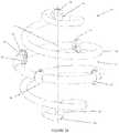
- FIG. 2illustrates a spiral implant device of the invention having a central strut
- FIG. 3illustrates a spiral implant device of the invention having a central strut, with marker clips secured within the spiral body;
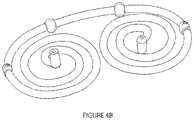
- FIGS. 4 A and Billustrate stages of fabrication for a spiral implant device of the invention
- FIG. 5illustrates a stage of fabrication for a spiral implant device of the invention
- FIG. 6illustrates a further stage fabrication for a spiral implant device of the invention
- FIG. 7illustrates an alternate embodiment of a spiral implant device of the invention
- FIGS. 8 A and Billustrate an additional embodiment of an implant device of the invention
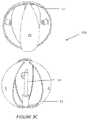
- FIGS. 9 A , B, C and Dillustrate an additional embodiment of an implant device of the invention.
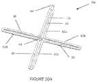
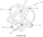
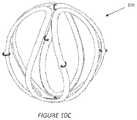
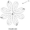
- FIGS. 10 A , B, C, and Dillustrate an additional embodiment of an implant device of the invention
- FIG. 11illustrates an embodiment of an implant device that has been placed in a surgical resection cavity
- FIG. 12illustrates another embodiment of an implant device that has been placed in a surgical resection cavity
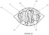
- FIG. 13illustrates another embodiment of an implant device that has been placed in a surgically created breast lumpectomy cavity
- FIG. 14illustrates another embodiment of an implant device that has been placed in a surgical resection cavity
- FIG. 15illustrates an additional embodiment of an implant device of the invention
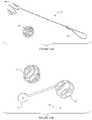
- FIGS. 16 A , B, and Cillustrate sizing tools with corresponding spiral implant devices of the invention
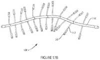
- FIGS. 17 A and Billustrate additional 2-dimensional embodiments of an implant device of the invention
- FIG. 18illustrates an alternative 2-dimensional embodiment of an implant device of the invention.
- FIG. 19illustrates an idealized tumor resection cavity in soft tissue as is known in the prior art.
- the invention described hereinuses implantable devices that can allow for more accurate targeting of external beam radiation to the region of tissue that is to be treated.
- the devicesprovide a 3-dimensional target or group of targets that is used to focus the radiation therapy treatment beams directly onto the targeted tissue—for example, the tissue surrounding a tumor resection cavity.
- the devicemay be formed of an absorbable material that is implanted intraoperatively during the same surgical procedure as the tumor resection and requires no second procedure to remove (it is resorbed in situ in the patient's body).
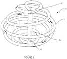
- the inventionincludes a spiral, bioabsorbable surgical implant 10 (illustrated in FIG. 1 A in a spherical configuration and in FIG. 1 B in an ellipsoid configuration) with at least one integral targeting marker component that is visible by means of clinical imaging (radiographic, ultrasonic, MRI, etc.).
- the implant 10has a relatively non-complex peripheral shape that can facilitate easy target delineation, such as spheres, ellipsoids, or cylinders. In this way, the implant (and/or the markers affixed thereto) can be visualized, and its contours (and thus the contours of the target tissue to be treated—typically marginal regions surrounding an excised tumor) can be readily determinable.
- the size and shape of the implantcan be varied to correspond to the most common resection cavity sizes and shapes.
- the devicemay be flexible and may be in its predetermined shape before placement and although it may tend toward that predetermined shape after implantation, the implant is subject to the forces applied to it by the patient's tissue and hence its shape is able to deform and conform to the adjacent tissue as well.
- the devicemay become integrated into the surrounding tissue as it is absorbed by the body, leaving the markers in proximity of the previously excised tumor for future clinical tracking.
- the devicecan be sized as needed for a particular surgery, however, preferred sizes range from about 2 cm to about 6 cm in longest diameter.
- the surgical implant 10 of the inventionis formed as a spiral.
- the spiral naturecan permit the implant 10 to be more flexible than it otherwise might be.
- the implant 10can flex along its axis 34 in the manner of bendable coil spring.
- the lack of continuous wallscan allow the implant to flex in directions other than along its axis. Such flexibility can allow for the target tissue, and the cavity into which the implant 10 is placed, to flex as the patient moves, making the implant more comfortable for the patient.
- the open nature of the spiralcan allow tissue growth and insinuation into the cavity which may reduce the incidence or effects of seroma, and in some instances may be able to reduce the volume of the target to be irradiated.
- the shape of the illustrated implant 10 in FIG. 1 Ais spherical, however, the implant could also be made in other shapes, such as a football-shaped ellipsoid (illustrated in FIG. 1 B ) or cylindrical.
- the term “spheroid”is expressly intended to include both spherical and ellipsoid shapes for the implant 10 —as such, both the embodiments of FIG. 1 A and FIG. 1 B are spheroid.
- the choice of shapemay depend on the shape and nature of the cavity into which the implant 10 is being placed. In the case of a lumpectomy cavity commonly related to breast cancer, a relatively spherical shape is common choice.
- the implant 10could have nay shape, regular shapes that are readily modeled by external radiation beam treatment devices are preferred. Such shapes can include spherical, scalene ellipsoid, prolate spheroid, and oblate spheroid shapes. Again, the use of the term “spheroid” herein is intended to include all of these spherical and ellipsoid shapes. Other regular shapes such as cylinders or squares could also be used, however, sharp corners might make it more difficult to shape radiation doses to the target tissue. In general, the implant 10 can have polar regions with an open framework extending between the polar regions.
- Such an open frameworkwould include a body 12 that provides sufficient stability to mark the boundaries of a tumor resection cavity, while having sufficient gaps 14 in the body to allow tissue around the cavity to infiltrate the device.
- the shape of the implant 10is created by a continuous or one-piece body 12 that is formed into a spiral having gaps 14 between the turns of the spiral, the overall spiral having a spherical shape with polar regions 16 , 18 .
- polar regions 16 , 18there is an extending portion 20 , 22 , which, in this embodiment, extends inward toward the center of the spherical shape.
- the open frameworkcan be designed to provide specific levels of flexibility.
- the illustrated spiral designacts as a spring.
- a spring constant for the device 10can be varied to achieve a desired flexibility. That is, by design the spring constant may provide a certain amount of force in order to keep the markers in their position along the margins of the cavity, but allow sufficient flexibility for patient comfort and to minimize scarring, therefore the device 10 can be optimized for its intended purposes.
- Preferred embodiments for use in treating breast cancerinclude those having a spring constant (denoted as “k”, in units of grams/mm) between about 5 and 15 grams per millimeter axial deflection for the 4 cm diameter devices (more preferably 8-12 g/mm), between about 10 and 25 g/mm axial deflection for the 3 cm diameter devices (more preferably 15-20 g/mm), and between about 25 and 70 grams/mm axial deflection for the 2 cm devices (more preferably 30-50 g/mm).
- kspring constant
- the inventorshave discovered that it can be beneficial to have higher k values for smaller diameter devices.
- Typical sizes of the devicerange from 2-6 cm in equatorial diameter and 2-8 cm in length. It is useful for the clinician to have a range of product diameters and lengths to choose from to provide the optimal configuration for a given patient.
- the implant 20is preferably able to be visualized on a medical imaging apparatus so that it can be used for targeting therapy.
- visualization characteristicsmay be enhanced by providing by visualization markers in the form of radio-opaque clips 24 , 26 , 28 that provide high contrast visibility on imaging devices.
- a first clip 24is provided at the “north pole”
- a second clip 26is provided at the “south pole”
- four clips 28are distributed substantially around the equatorial region of the spherical implant 10 .
- This clip arraypermits a specific outlining, or in other words a characterization of the extent of the borders of the tissue cavity in all 3 dimensions, and in this embodiment, the xy, zy and xz planes.
- clipscan be used to provide more detailed or less detailed tissue site identification, as needed.
- clipsare preferentially provided at the two poles and also in some number distributed substantially about the equator; or elsewhere along its spiral length. In this manner, even where the spherical implant flexes in vivo; or the tissue around the cavity moves or flows, the 3 dimensional shape of the tissue region can be identified, based on the location of the clips. It is worth noting that, with currently available high resolution imaging systems, including CT, mammography, MRI, and ultrasound, the presence of the clips may not be necessary to image the implant and hence image the surrounding soft tissue. The mere presence of the bioabsorbable body, which need not contain air gaps in the body material, can in some cases, be sufficient to delineate or demarcate the desired tissue location.
- each of the north and south pole clips 24 and 26is located within the respective polar region extension 20 , 22 .
- Each of the clipsis secured to the body material.
- the polar clipis configured as a wire element that is folded onto itself, with the wire ends slightly flared prior to assembly. During assembly the clip is inserted into a cylindrical hole in the polar region. The flared ends of the clip serve as a unidirectional gripping element that prevents the polar clip from backing out of the hole once it is installed.
- the equatorial clipsmay be secured to body 12 using pockets or through-holes 30 created in regions 32 that exist for the purpose of providing the clips with a location to provide secure attachment.
- These equatorial clips 28also made from metal wire can be attached by providing that the middle portion of the clip resides within the hole 30 , and the end portions of the clip curve around the region 32 , as illustrated, to fix them securely to the body 12 in the shape of a “D”.
- This D shapefacilitates the differentiation of these marker elements from the polar clips and from conventional haemostatic clips that may be used to control bleeding during the surgical procedure.
- the peripheral clips 28may be placed in a lumen of a long spiral segment 12 of bioabsorbable tubing.
- the clipscan be made from any biocompatible, radio-opaque material, such as titanium, stainless steel, gold or composite polymer materials (e.g., made with carbon or Barium Sulfate) having the desired visualization characteristics.
- the bioabsorbable body 12itself may have visualization properties in addition to or in place of the clips 24 , 26 , 28 . That is, the characteristics of the body material, or a coating on the body, may be chosen so that the body itself may be visualized on an imaging device and used for targeting.
- the body 12may have radiodensity (or magnetic spin recovery when using MRI) that is different rom the tissue surrounding the cavity into which the implant 10 is placed for the purpose of making the body 12 visible on an imaging device.
- breast tissuecan present values ranging from ⁇ 140 to 50 on the Hounsfield scale—a linear transformation of the original linear attenuation coefficient measurement to one in which the radiodensity of distilled water at standard pressure and temperature (“STP”) is defined to have a Hounsfield number of zero, while the radiodensity of air at STP is defined to have a Hounsfield number of ⁇ 1000.
- STPstandard pressure and temperature
- the density of the body 12should not be so high as to impart significant attenuation of the radiation beams or imaging artifact, which may result in clinically compromised target delineation or altering the dose delivered by a clinically significant amount.
- the density of the body 12may in some cases be indistinguishable from that of the surrounding tissue for visualization and treatment purposes.
- the body 12 material and/or the clipsmay have a roughened or faceted surface finish to enhance the ultrasound imaging ability of the visualization device.
- Various materials that could be used to construct body 12include known bioabsorbable materials such as polyglycolic acid (PGA, e.g., Dexon, Davis & Geek); polyglactin material (VICRYL, Ethicon); poliglecaprone (MONOCRYL, Ethicon); and synthetic absorbable lactomer 9-1 (POLYSORB, United States Surgical Corporation) and polydioxanone.
- Other materialsinclude moldable bioabsorbable materials such as poly lactic acid (PLA), including Poly L-lactic acid (PLLA) and various PLA/PGA blends. These blends can include caprolactone, DL lactide, L lactide, glycolide and various copolymers or blends thereof.
- the materialscan be modified, by cross-linking, surface texturing, or blended with one another to control degradation rates over varying lengths of time, after which they are substantially or completely resorbed.
- Another manner in which degradation rates can be alteredis by subjecting them to additional radiation in the dose ranges typically used for radiation sterilization. For example, subjecting the device to e-beam radiation in the dose range of 25 to 40 kiloGray (kGy) is typical for an adequate, validated sterilization cycle. However, subjecting the device to an additional 25 to 75 kGy can be useful to accelerate the in-situ degradation rate without significantly adversely affecting the functional short-term mechanical properties of the device.
- the mechanical properties of body 12are maintained for a long enough for treatment to take place.
- the body 12lasts long enough for tissue to infiltrate the cavity such that the position of the visualization markers is fixed within the tissue.
- the materialis preferably rigid enough for the overall effect of the spiral shape to behave in a resiliently deformable manner after implantation.
- a cross sectional shape of the body 12may also be selected to achieve the desired spring constant and absorbance parameters.
- body 12may have a cross section that is circular, oval, ovoid, cruciform, or rectangular. Other shapes can also be used.
- the implant 10may also have a strut 36 extending in the direction of its longitudinal axis 34 .
- the strut 36can be connected between the north and south polar extensions 20 , 22 .
- the strut 36provides structural support, but also allows some translation of at least one polar region toward or away from the other polar region with respect to an unflexed position of the spiral body 12 .
- the spiral body 12will flex in the manner of a spring and particularly in compression.
- Strut 36allows compression along the longitudinal axis, but may also provide a stop to prevent over compression of the spiral body 12 .
- the strut 36is a tubular element that fits over each of extensions 20 , 22 and maintains a fixed relationship with one extension while sliding with respect to the other extension. This configuration would allow the spiral body 12 to be compressed until an edge of the tubular strut 36 contacted one of the polar regions 16 , 18 which would act as a stop.
- the strut 36could slide with respect to each of the extensions 20 , 22 .
- the strut 36could comprise two overlapping tubes that slide with respect to each other in the longitudinal direction and opposed ends of such a strut could be fixed to the polar extensions 20 , 22 .
- the strut 36could be fixed to both extensions 20 , 22 with no internal sliding.
- body 12is formed into two substantially planar, opposed, and connected spirals.
- Body 12could be extruded and then heat-formed as shown in FIG. 5 (the shaping of a thermoplastic material by heating it and causing a permanent deformation (such as bending) that remains after the material cools) into the desired shapes described above, however, such handling of bioabsorbable is difficult and repeatability in forming the shapes can be challenging.
- this first stepis carried out by injection molding as shown in the spiral forms of FIGS. 4 AB and C.
- This shapecan be molded from a simple two part mold without the need for side pulls, which allows for repeatability yet modest tooling costs.
- the molded partallows for more surface detail, for example at the ends of the part—rounded ends with pockets for visualization markers or fabrication fixtures may be incorporated into the design, as illustrated for example in FIG. 4 A .
- Pockets for additional visualization markerscan be molded along the length of the body at appropriate intervals, as shown in FIG. 4 B .
- the entire body 12may at this stage be substantially planar to facilitate injection molding.
- substantially planarwe mean of a configuration that is able to be injection molded without the need for side pulls, or that can be die cut from a sheet form of the body material.
- Visualization markersmay also be attached to body 12 at this stage where the body is substantially planar, as shown in FIG. 4 C , which is conducive to automated assembly methods.
- left spiral 40includes a north polar extension 42
- opposed right spiral 44includes a south polar extension 46
- a connecting segment 48connects the two opposed spirals.
- FIG. 5illustrates a similar embodiment to FIG. 4 , but lacking polar extensions, which could be heat-formed later, or omitted completely—especially if a central strut is not desired.
- a subsequent step in a fabrication processresults in a device that is illustrated in FIG. 6 , where the configuration of FIG. 5 has been heat-formed so that one spiral 40 is located above the other spiral 44 so that the spirals share a common longitudinal or central axis.
- either spiralcould go over the other.
- the left spiral 40preferably would be placed on top of the right spiral 44 so that the polar extensions extend toward each other—that is, toward the center of the finished spiral implant.
- the centers of the overlapping spirals 40 , 44can be reformed, (e.g., over a mandrel) so that body 12 takes the general shape of a sphere.
- the final shape of the final implantcan be determined during this heat forming step. For example, heat forming the centers to project out of plane less than the full radius distance of a sphere shape will result in a flattened sphere. Heat forming beyond the full radius distance will elongate the sphere to a football shape as shown in FIG. 1 B . Forming one spiral side farther from the midline than the other will result in an egg shape. In embodiments in which the central strut is desired, the strut may next be added.
- the body 12may be placed around a spheroid forming mandrel and heated to form the final desired shape.
- the forming mandrelmay have channels along its surface to hold the part in a given position during the heat-forming process.
- FIG. 7shows a device formed as shown in FIG. 6 , with the addition of marker clips which are placed at desired locations along the central lumen of the body of the device. These marker clips may be placed in the lumen before or after final heat forming into the final spheroid spiral shape.
- FIGS. 8 through 10all describe alternate embodiments where the bioabsorbable marker component (e.g. body 12 ) is initially formed in a relatively planar configuration (e.g. for ease of injection molding) and then the component is subsequently heat-formed into its final spheroid or other three dimensional configuration.
- the embodimentshave an open architecture to maximize the opportunity for tissue ingrowth, tissue movement, tissue approximation and/or fluid communication across the peripheral boundary of the marker device.
- the open architecturealso allows for the passage of suture around a portion of the device by the clinician to help secure the device to adjacent tissue (e.g., chest wall) to further immobilize the device.
- the marker devices described hereincomprise a resilient framework of bioabsorbable elements with locations for periodic secure attachment of radiodense marker elements (e.g., titanium wire) along the periphery of the device.
- radiodense marker elementse.g., titanium wire
- the flexibility and conformability of the deviceallows for device deformation for increased comfort and conformance to the surrounding tissue in which the device is placed.
- peripheral boundarywe are referring not only to the boundary edge of the marker device itself but also to the “empty space” regions in between the portions of the marker device that are generally consistent with the perimeter of the device.
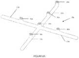
- FIG. 8 Ashows an alternate embodiment of the device 10 a where the bioabsorbable component is molded in a planar, cross-like configuration with a body having four branches, 12 a, 12 b, 12 c, and 12 d.
- Each branchincludes a feature 30 a for attaching a marker about an equator of the device, while one branch 12 a includes at its end a feature 30 a for attaching a north pole marker and the center of the cross includes a feature 30 a for attaching a south pole marker.
- FIG. 8 Ashows an alternate embodiment of the device 10 a where the bioabsorbable component is molded in a planar, cross-like configuration with a body having four branches, 12 a, 12 b, 12 c, and 12 d.
- Each branchincludes a feature 30 a for attaching a marker about an equator of the device, while one branch 12 a includes at its end a feature 30 a for attaching a north pole marker and the center of the cross includes
- FIG. 8 Bshows the device after the component has been heat formed (e.g., around a spherical mandrel with recessed grooves) to generate a spherical device 10 a having north and south polar regions 16 , 18 .
- Other shapes described hereincould also be formed in this manner, as well as, shapes formed with more or fewer branches.
- the number of brancheswill be based upon the width of the branches, the desired size of gaps between the branches in the finished device (and thus the device's “openness”), and the number of markers desired about the equator of the device.
- FIGS. 9 A through 9 DAnother embodiment of the device is shown in FIGS. 9 A through 9 D .
- a first portion 52 of a bioabsorbable component 106is molded in the form as shown in FIG. 9 A having three petal-like branches 12 e, 12 f, and 12 g.
- the three cylindrical protrusions 54 in the center of each petal-like elementcontain a radiopaque marker (not shown) such as a titanium wireform for use as equatorial markers.
- the central cylindrical protrusion 56comprises a fastening means (e.g., press-fit or mating threads) for assembling the device and an also include a radiopaque marker (not shown).
- the component 52can subsequently be heat-formed around a curved mandrel to create a component as illustrated in FIG. 9 B .
- a central axial extension 58can be added to two portions 52 to create an assembled bioabsorbable device 10 b as shown as FIG. 9 C , which is the exploded
- FIGS. 10 A to 10 Dshow yet another embodiment of the device 10 c where the bioabsorbable component is molded in an alternating continuous filament 12 h configuration forming four loops 62 a - 62 d in the form of a cross with each loop being open towards the center.
- Each loop 62 a - 62 dincludes a feature 30 to allow placement of equatorial markers 28 .
- Loop 62 aincludes a feature 64 for placement of a north polar marker 24 , while a feature 66 for placement of a south polar marker 26 is located at the center of the device 10 c between any two loops.
- FIG. 10 A to 10 Dshow yet another embodiment of the device 10 c where the bioabsorbable component is molded in an alternating continuous filament 12 h configuration forming four loops 62 a - 62 d in the form of a cross with each loop being open towards the center.
- Each loop 62 a - 62 dincludes a feature 30 to allow placement of
- FIG. 10 Bshows the device 10 c after the component has been heat formed (e.g., around a spherical mandrel with recessed grooves) and with the markers 24 , 26 , 28 added.
- the forming mandrelnot only creates a spherical shape of the final configuration but the recessed grooves in the mandrel also help space apart the filaments to create a relatively even spacing of the bioabsorbable filament (and thus equal spacing of gaps or openings to allow tissue infiltration) along and throughout the spherical surface of the device.
- FIG. 10 C and FIG. 10 Dshow top and side views, respectively of the device 10 c embodiment shown in FIG. 10 B .
- FIG. 11shows a spiral marker 10 as described in FIG. 1 that has been placed in a lumpectomy cavity 72 of a patient's breast.
- the cavityis in the process of being closed with suture 64 and one can appreciate the tissue infiltrating 76 into the interstices of the spiral device 10 .
- the open architecture of the deviceallows the tissue to flow or otherwise move within the peripheral boundary of the device as the tissue is pulled together and secured by suture.
- This devicethus allows the surgical cavity site (and its margins) to be marked in a 3 dimensional fashion for subsequent imaging even though the lumpectomy cavity itself may be surgically altered or naturally altered in original size and/or shape.
- the lumpectomy cavitymay be naturally (i.e. passively) altered in size or shape by partially or totally collapsing on itself or some cases by expanding due to seroma buildup within the lumpectomy cavity in the post-surgical period.
- FIG. 12shows a similar device 10 in another lumpectomy cavity 72 and one can appreciate the degree to which the surrounding tissue has infiltrated 76 within and flowed around the marker 28 .
- these open architecture 3-dimensional tissue markers as described hereinallow the clinician to demarcate the closed and/or collapsed cavity with a level of 3-dimensional accuracy that has not previously been possible.
- FIG. 13shows device 10 after placement in a lumpectomy cavity 131 at the time of surgery via a standard surgical incision 132 .
- the peripheral boundary 134 of the deviceis defined as the continuous overall surface shape that is defined by the outer regions or peripheral surface elements (for example 135 ) of the device.
- the peripheral boundaryis an ovoid surface, a view of which is shown in this figure as an oval dotted line 134 .
- Cavity boundary tissuecan be see to insinuate, penetrate, and/or flow between and around the elements of the device, thereby crossing the peripheral boundary of the device at for example, tissue locations 136 and 137 .
- a lumpectomy cavityis created by surgically removing breast tissue via a skin incision (which may be minimally invasive, e.g. via tunneling from the areola), the cavity is sized using a sizer or other sizing method (e.g. direct examination of the lumpectomy specimen or cavity), the appropriately sized 3 dimensional open architecture bioabsorbable tissue marker is placed directly into the lumpectomy cavity via the surgical incision causing the breast tissue at the margin of the cavity to actively (e.g. via suture closure) or passively insinuate or otherwise move across the peripheral boundary of the tissue marker device, and then the wound or skin is closed in standard surgical fashion.
- a skin incisionwhich may be minimally invasive, e.g. via tunneling from the areola
- the cavityis sized using a sizer or other sizing method (e.g. direct examination of the lumpectomy specimen or cavity)
- the appropriately sized 3 dimensional open architecture bioabsorbable tissue markeris placed directly into the lumpectomy cavity via the surgical incision causing
- the deviceis used as above but with the added step of passing some suture around one or more portions of the device and then passing the suture through adjacent tissue to tether or otherwise further secure the device to the adjacent tissue.
- the degree of tissue insinuation within the boundaries of the marker devicecan be fairly limited. This instance can be appreciated in FIG. 14 , where a marker device 10 of the type described in FIG. 1 has been placed in a lumpectomy cavity 72 of a patient's breast. One can see that in this approach, only a modest amount of tissue has infiltrated between the spiral elements and a significant portion of the original cavity remains free of tissue, with the marker device (including the marker clips) delineating the margins of the lumpectomy cavity.
- FIG. 15show an alternate embodiment 10 d where a mesh-like structure comprised of biodegradable filaments 82 is formed into a cavity-sized open-architecture shell-like structure with marker clips 84 secured at various peripheral locations of the structure.
- the marker clipsare still placed at the north and south poles and with four markers placed around the equator. This construction maximizes the overall diameter of the device while using a minimum mass of biodegradable material.
- the mesh-like structure(woven or braided filaments, or die-cut sheet) is also conformable yet still maintains a 3-dimensional volumetric characterization of the adjacent tissue as it resides within the cavity.
- the marker clipsreside at the periphery of the device and hence optimizes visualization of the boundaries of the surgical cavity.
- the degree of tissue infiltration across the boundary of the device perimetercan be varied by the chosen gap size (e.g., from 1 mm to 10 mm). All versions within this gap size range are of an open-architecture design where fluids (e.g. blood, seroma, lymphatic fluid) can freely pass across the peripheral boundary of the device after implantation.
- fluidse.g. blood, seroma, lymphatic fluid
- a method according to the invention for treating these and other malignanciesbegins by surgical resection of a tumor site to remove at least a portion of the cancerous tumor and create a resection cavity as illustrated in FIG. 18 .
- an entry site or incision 102is created in patient 100 in order to remove tissue and create a cavity 104 .
- FIG. 7visually represents the surgical resection cavity in concept, it is important to note that most cavities are not that simplistically configured in the 2-8 week postoperative period that they are most likely to be visualized in the clinical imaging environment.
- Landis et al(“Variability among breast radiation oncologists in delineation of the postsurgical lumpectomy cavity,” 67(5) Int J Radiat Oncol Biol Phys 1299-308 (2007)) have documented the difficulty in delineating the cavity boundaries to be targeted in the postoperative period. Landis et al also document the range of sizes and shapes and geometric uncertainties that can be typically seen in the clinical environment. Tissue margins can be difficult to delineate due to uncertainty about the extent and position of the excision cavity and its adjacent tissue. Therefore, a device of the present invention that is placed into the surgical cavity at the time of cavity resection will demarcate these tissue boundaries at the time the cavity is surgically created, so that postoperatively (e.g.
- the tissue boundariesare much easier to identify (or identified with higher confidence as to their configuration and specific location).
- the marker clips of the devicewill be visible and in other cases, the bioabsorbable carrier material may also be visible in addition to the marker clips. In either case, a more accurate delineation of the tissue adjacent to the lumpectomy cavity can be documented than would be possible had the marker device of the present invention not been placed, or had individual discrete marking devices (e.g. clips) been placed into the cavity as an alternative.
- an implant of the invention(using any of the embodiments described herein) is placed into the tumor resection cavity 104 .
- Placementcan occur prior to closing the surgical site 102 such that the surgeon intra-operatively places the device, or alternatively, a device can be inserted after the initial surgical resection (e.g., during a re-excision to remove more tissue due to positive or inadequate surgical margins). In some cases, a new incision for introduction of the device may be created. In either case, the device, whose peripheral surface is preferably sized and configured to reproducibly demarcate the tissue surrounding the resection cavity 104 , is placed within the resected tissue cavity.
- a sizing toolin order to help the clinician choose the proper size and shape of device to be implanted for a given surgical cavity. It is particularly useful for the sizing tool to represent not only a similar general size (e.g. width and length) of the device to be implanted, but also to represent the general device configuration and/or device flexibility as well.
- a sizing tool 92is shown in FIGS. 16 A and 16 B .
- the exemplary sizing tool 92includes a handle portion 94 and a sizing portion 96 that represents the size of a particular size of implantable device.
- an implantable device 10that is represented by the sizing tool.
- 16 Cshows an array of such sizing tools 92 with their correspondingly sized and shaped implantable marker devices 10 .
- the clinicianchooses a particular sizing tool from a set of reusable sterile sizing tools, such as that shown in FIG. 16 C .
- the clinicianplaces the spheroid end of the sizing tool into the surgical cavity.
- the tissue surrounding the toolmay be surgically approximated by one or more temporary stitches or staples, to give the clinician a sense of how the tissue interacts with the sizing tool and hence how the tissue will interact around the implantable marker device.
- an alternately sized or shaped sizing toolmay be used until the desired interaction with the surrounding tissue is achieved. Subsequently, the sizing tool is removed from the wound and the clinician selects the implant device that most closely matches the sizing tool configuration, and then places the implant device in the tissue cavity. Subsequently the breast tissue interacts with the implant in a fashion predicted by the sizer tool and the clinician closes the skin incision.
- the implantoccupies (at least a portion of) the tissue cavity 104 and demarcates the surrounding target tissue until such time as the implant resorbs.
- a substantial portion of the devicecan conform to the walls of the resection cavity.
- “Substantial portion”is used herein in this context to mean greater than or equal to about 25% of the outward facing surface of the implant is in direct apposition to the surrounding tissue. Given the irregularities of many lumpectomy cavity shapes, not all of the surface of the implant may be in direct apposition to the surrounding tissue.
- the implantfully conforms to the surrounding tissue—where fully conforms means greater than or equal to about 95% of the implant's surface will be in direct apposition to surrounding tissue. Regardless of the percent of the device outer surface that comes in contact with the surrounding tissue, because of the open architecture of the device, there typically remains a portion of the resection cavity inner surface that does not come into contact with the implanted device. Otherwise the devices would not be of the open-architecture design, where there is free communication of fluids and tissue across the peripheral boundary of the device after implantation.
- a defined tissue regionis provided so that radiation can more accurately be delivered to the previously irregular or indeterminate tissue cavity walls.
- This defined surfacecan be delineated via a variety of imaging modalities such as ultrasound, MRI and CT or other x-ray by the bioabsorbable portion of the device or by the marker clips, or by both.
- the devicemay help reduce error in the treatment procedure introduced by tissue movement.
- the positioning and stabilization provided by the implant devicemay greatly improve the effectiveness of radiation therapy by facilitating radiation dosing and improving its accuracy.
- the resultis a treatment method which concentrates radiation on target tissue and helps to minimize damage and preserve the surrounding healthy tissue.
- lower dosecan be delivered to adjacent normal tissue, which improves the suitability for accelerated radiation treatment regimens (e.g., fewer dose fractions at a higher dose rate).
- the device and the surrounding target tissuecan preferably be visualized with an imaging device, including by way of non-limiting example, x-ray (kV or MV), conventional (2-D) mammography, 3-D mammography (including mammographic tomosynthesis, e.g., SELENIA Tomosynthesis by Hologic, Inc.), ultrasound, MRI, CT scan, PET, SPECT, and combinations thereof.
- an imaging deviceincluding by way of non-limiting example, x-ray (kV or MV), conventional (2-D) mammography, 3-D mammography (including mammographic tomosynthesis, e.g., SELENIA Tomosynthesis by Hologic, Inc.), ultrasound, MRI, CT scan, PET, SPECT, and combinations thereof.
- These imaging devicesprovide a picture of the implant device and the surrounding target tissue to assist with the planning of external radiation therapy.
- the devicecan delineate the cavity boundaries so that a target volume may be derived.
- the devicethen provides a target for more accurate repositioning of the patient
- the beamscan either move with the target, can reshape dynamically to conform to a moving target or can be turned on and off as the target moves out of and back into the beams' path.
- the imaging proceduresprovide a map of the residual tissue margin and assist with targeting tissue for radiation dosing.
- the radiation beamsare then adapted for delivering a very precise radiation dose to the target tissue.
- the improved targeting capabilityreduces the patient setup errors (target positioning relative to the treatment beam). Both factors improve target tissue conformality, reduce the radiation exposure to normal tissues surrounding the targeted volume of the body, and can allow for smaller target volumes than would otherwise be prescribed due to the decrease in uncertainty of the tissue margins of the cavity.
- Some treatment regimensrequire repeated radiation dosing over a course of days or weeks, and the device can be used in those cases to repeatedly position the tissue surrounding the resected tumor cavity. These steps can be repeated as necessary over the course of a treatment regimen.
- the implanted deviceremains in place without intervention, i.e., without removal or actions to change its configuration, throughout the course of treatment.
- the devices and procedures described hereinmay be used for other anatomic sites as well, (e.g. muscle for sarcoma, liver for liver tumors) including any regions were tissue is removed and the patient may require targeted radiation treatment at or near the site of tissue removal.
- the devicemay also be placed in the cavity created by the open surgical biopsy of high risk non-cancerous or ultimately benign breast lesions as well as other non-cancerous tissue sites. Doing so identifies the cavity for future breast imaging studies, which can be useful for long-term patient monitoring.
- the 3-D devicesdemarcate the boundaries of more 3 dimensional structure (e.g., lumpectomy cavity) these 2-D devices may be more useful to demarcate the more planar or curvilinear boundaries of tissue that may arise from surgical excision (e.g., during breast reduction).
- FIGS. 4 , 5 , and 17Such planar yet compliant and conformable versions are shown in FIGS. 4 , 5 , and 17 . These designs are useful for identifying the tissue boundaries that ultimately are reapproximated, actively or passively, during various surgical procedures.
- the surgical procedures that may benefit from these 2-dimensional designsare procedures that require excision of soft tissue followed by reapproximation of the resection boundaries (e.g., as in breast reduction or lung-wedge resections).
- FIGS. 4 and 5illustrate a spiral planar form of a 2-D style marker that can be placed surgically into a region of tissue that can be surgically approximated.
- the spiral elementsare free to flex to conform to the tissue planes as the tissue is surgically approximated.
- FIG. 17 Aillustrates another embodiment 10 e comprising an array of flexible spines 112 made of a bioabsorbable polymer emanating from a central region 114 .
- a radiopaque marker 28 of the type described previouslyresides at the extremity of each of the spines.
- a marker clipmay reside at the central region as well (not shown).
- the deviceis placed at the time of surgery along the surface of the region of tissue to be approximated.
- the tissue surfacescan be irregular in surface shape (e.g., non-planar) and so as the tissue surfaces may be approximated (e.g., by surgical suturing) yet the device is still able to flex and conform to the irregular surface shapes of the tissue surfaces.
- the open architecture of this structureallows for unencumbered fluid passage and tissue mobility while still demarcating the excised issue boundaries.
- FIG. 17 Billustrates yet another embodiment 10 f similar to the device described with respect to FIG. 17 A except that the central region 116 is a linear spine like element, which is also made of bioabsorbable material. Marker elements reside not only on the peripheral spines but also at periodic intervals along the central spine of the device. In use the device may be cut at various locations along the spine to best fit the anatomical site it is to be placed, prior to placement at the tissue site.
- FIG. 18illustrates yet another embodiment 10 g where the device is comprised of a flexible bioabsorbable mesh or screen 118 that contain marker 28 elements that reside fixedly to the periphery or other locations along the flexible plane.
- radiopaque markersare comprised of Titanium wire elements that envelop the filaments of the mesh or screen material.
- the wire elementsmay be enveloped within the bioabsorbable material and oriented either parallel or perpendicular to the generally planar flexible surface of the embodiment (as shown in FIG. 4 B ).
- the perpendicular marker elementsis that the marker elements may partially embed (like cleats of a shoe sole) into the adjacent tissue to secure the position of the device along the surface of the tissue to be approximated.
Landscapes
- Health & Medical Sciences (AREA)
- Life Sciences & Earth Sciences (AREA)
- Surgery (AREA)
- Biomedical Technology (AREA)
- Engineering & Computer Science (AREA)
- Heart & Thoracic Surgery (AREA)
- Pathology (AREA)
- Nuclear Medicine, Radiotherapy & Molecular Imaging (AREA)
- Animal Behavior & Ethology (AREA)
- General Health & Medical Sciences (AREA)
- Public Health (AREA)
- Veterinary Medicine (AREA)
- Oral & Maxillofacial Surgery (AREA)
- Medical Informatics (AREA)
- Molecular Biology (AREA)
- Radiology & Medical Imaging (AREA)
- Prostheses (AREA)
- Radiation-Therapy Devices (AREA)
Abstract
Description
Claims (27)
Priority Applications (3)
| Application Number | Priority Date | Filing Date | Title |
|---|---|---|---|
| US16/661,663US11529211B2 (en) | 2012-04-26 | 2019-10-23 | Surgical implant for marking soft tissue |
| US17/953,996US11944509B2 (en) | 2012-04-26 | 2022-09-27 | Surgical implant for marking soft tissue |
| US18/593,019US12357418B2 (en) | 2012-04-26 | 2024-03-01 | Surgical implant for marking soft tissue |
Applications Claiming Priority (3)
| Application Number | Priority Date | Filing Date | Title |
|---|---|---|---|
| US13/456,435US20130289389A1 (en) | 2012-04-26 | 2012-04-26 | Surgical implant for marking soft tissue |
| US15/920,126US10500014B2 (en) | 2012-04-26 | 2018-03-13 | Surgical implant for marking soft tissue |
| US16/661,663US11529211B2 (en) | 2012-04-26 | 2019-10-23 | Surgical implant for marking soft tissue |
Related Parent Applications (1)
| Application Number | Title | Priority Date | Filing Date |
|---|---|---|---|
| US15/920,126ContinuationUS10500014B2 (en) | 2012-04-26 | 2018-03-13 | Surgical implant for marking soft tissue |
Related Child Applications (1)
| Application Number | Title | Priority Date | Filing Date |
|---|---|---|---|
| US17/953,996ContinuationUS11944509B2 (en) | 2012-04-26 | 2022-09-27 | Surgical implant for marking soft tissue |
Publications (2)
| Publication Number | Publication Date |
|---|---|
| US20200113647A1 US20200113647A1 (en) | 2020-04-16 |
| US11529211B2true US11529211B2 (en) | 2022-12-20 |
Family
ID=49477870
Family Applications (6)
| Application Number | Title | Priority Date | Filing Date |
|---|---|---|---|
| US13/456,435AbandonedUS20130289389A1 (en) | 2012-04-26 | 2012-04-26 | Surgical implant for marking soft tissue |
| US13/656,068ActiveUS10413381B2 (en) | 2012-04-26 | 2012-10-19 | Surgical implant for marking soft tissue |
| US15/920,126ActiveUS10500014B2 (en) | 2012-04-26 | 2018-03-13 | Surgical implant for marking soft tissue |
| US16/661,663Active2033-07-19US11529211B2 (en) | 2012-04-26 | 2019-10-23 | Surgical implant for marking soft tissue |
| US17/953,996ActiveUS11944509B2 (en) | 2012-04-26 | 2022-09-27 | Surgical implant for marking soft tissue |
| US18/593,019ActiveUS12357418B2 (en) | 2012-04-26 | 2024-03-01 | Surgical implant for marking soft tissue |
Family Applications Before (3)
| Application Number | Title | Priority Date | Filing Date |
|---|---|---|---|
| US13/456,435AbandonedUS20130289389A1 (en) | 2012-04-26 | 2012-04-26 | Surgical implant for marking soft tissue |
| US13/656,068ActiveUS10413381B2 (en) | 2012-04-26 | 2012-10-19 | Surgical implant for marking soft tissue |
| US15/920,126ActiveUS10500014B2 (en) | 2012-04-26 | 2018-03-13 | Surgical implant for marking soft tissue |
Family Applications After (2)
| Application Number | Title | Priority Date | Filing Date |
|---|---|---|---|
| US17/953,996ActiveUS11944509B2 (en) | 2012-04-26 | 2022-09-27 | Surgical implant for marking soft tissue |
| US18/593,019ActiveUS12357418B2 (en) | 2012-04-26 | 2024-03-01 | Surgical implant for marking soft tissue |
Country Status (7)
| Country | Link |
|---|---|
| US (6) | US20130289389A1 (en) |
| EP (4) | EP4628051A3 (en) |
| JP (2) | JP6366572B2 (en) |
| AU (1) | AU2013251545B2 (en) |
| CA (1) | CA2871606A1 (en) |
| ES (2) | ES2794936T3 (en) |
| WO (1) | WO2013163381A1 (en) |
Families Citing this family (39)
| Publication number | Priority date | Publication date | Assignee | Title |
|---|---|---|---|---|
| US9014787B2 (en)* | 2009-06-01 | 2015-04-21 | Focal Therapeutics, Inc. | Bioabsorbable target for diagnostic or therapeutic procedure |
| US20130289389A1 (en) | 2012-04-26 | 2013-10-31 | Focal Therapeutics | Surgical implant for marking soft tissue |
| US8989843B2 (en)* | 2012-06-05 | 2015-03-24 | DePuy Synthes Products, LLC | Methods and apparatus for estimating the position and orientation of an implant using a mobile device |
| USD715442S1 (en)* | 2013-09-24 | 2014-10-14 | C. R. Bard, Inc. | Tissue marker for intracorporeal site identification |
| USD716451S1 (en)* | 2013-09-24 | 2014-10-28 | C. R. Bard, Inc. | Tissue marker for intracorporeal site identification |
| USD716450S1 (en) | 2013-09-24 | 2014-10-28 | C. R. Bard, Inc. | Tissue marker for intracorporeal site identification |
| USD715942S1 (en) | 2013-09-24 | 2014-10-21 | C. R. Bard, Inc. | Tissue marker for intracorporeal site identification |
| US20160287901A1 (en)* | 2013-11-08 | 2016-10-06 | Dumaine Precision Inc. | Surgical cavity sizers for brachytherapy and intraoperative radiation therapy |
| US11883275B2 (en) | 2014-06-11 | 2024-01-30 | Bard Shannon Limited | In vivo tissue engineering devices, methods and regenerative and cellular medicine employing scaffolds made of absorbable material |
| US11638640B2 (en) | 2014-06-11 | 2023-05-02 | Bard Shannon Limited | In vivo tissue engineering devices, methods and regenerative and cellular medicine employing scaffolds made of absorbable material |
| CA2955956C (en) | 2014-07-25 | 2022-10-18 | Focal Therapeutics, Inc. | Implantable devices and techniques for oncoplastic surgery |
| EP3316784B1 (en)* | 2015-06-30 | 2021-08-04 | Canon U.S.A., Inc. | Fiducial markers, systems, and methods of registration |
| US9949821B2 (en)* | 2015-12-22 | 2018-04-24 | Biosense Webster (Israel) Ltd. | Colored silicone for implant safety |
| US11191611B2 (en) | 2016-06-03 | 2021-12-07 | Somatex Medical Technologies Gmbh | Marking device and implantation system |
| KR101876457B1 (en)* | 2016-10-13 | 2018-07-10 | 연세대학교 산학협력단 | Personalized bolus for compensating thickness of chest wall and method of manufacturing the same |
| WO2018097891A1 (en) | 2016-11-23 | 2018-05-31 | Hologic, Inc. | Biopsy site marker |
| US11219502B2 (en) | 2017-09-11 | 2022-01-11 | Medtronic Advanced Energy, Llc | Transformative shape-memory polymer tissue cavity marker devices, systems and deployment methods |
| US10646727B2 (en) | 2017-11-13 | 2020-05-12 | Positive Energy, Llc | Anchored brachytherapy device |
| EP4628023A2 (en) | 2017-12-11 | 2025-10-08 | Hologic, Inc. | Ultrasound localization system with advanced biopsy site markers |
| US11324567B2 (en) | 2018-02-01 | 2022-05-10 | Medtronic Advanced Energy, Llc | Expandable tissue cavity marker devices, systems and deployment methods |
| US11759306B2 (en) | 2018-03-12 | 2023-09-19 | Bard Shannon Limited | In vivo tissue engineering devices, methods and regenerative and cellular medicine employing scaffolds made of absorbable material |
| US11259913B2 (en) | 2019-02-06 | 2022-03-01 | Susan Scott | Breast implant with position marker |
| US11504546B2 (en) | 2019-02-28 | 2022-11-22 | Cowles Ventures, Llc | Needle guidance device for brachytherapy and method of use |
| US11524176B2 (en) | 2019-03-14 | 2022-12-13 | Cowles Ventures, Llc | Locator for placement of fiducial support device method |
| CN112566544B (en) | 2019-05-08 | 2025-09-19 | 阿特瑞克尔公司 | Biological tissue location positioning and marking |
| CN112336332B (en)* | 2019-08-09 | 2024-11-29 | 通用电气精准医疗有限责任公司 | Magnetic resonance imaging scanning method and magnetic resonance imaging system |
| CN110507451A (en) | 2019-08-29 | 2019-11-29 | 上海翰凌医疗器械有限公司 | Valve support and artificial valve with same |
| US11406489B2 (en) | 2019-10-07 | 2022-08-09 | Cornell University | Implant with fiducial markers |
| US20210220522A1 (en)* | 2020-01-16 | 2021-07-22 | Hologic, Inc. | Hydrogel-based implantable device and related methods |
| US20230038320A1 (en)* | 2020-02-06 | 2023-02-09 | Somatex Medical Technologies Gmbh | Implantable marker body for breast treatment |
| BR122023022155A2 (en) | 2020-03-23 | 2024-02-20 | Bard Shannon Limited | IMPLANTABLE PROSTHESIS COMPRISING A BODY OF BIOCOMPATIBLE MATERIAL |
| US20230149117A1 (en)* | 2020-04-06 | 2023-05-18 | Tepha, Inc. | Medical implants for marking surgical sites |
| JP7403424B2 (en)* | 2020-09-29 | 2023-12-22 | 日本ピストンリング株式会社 | Manufacturing method for medical markers |
| US11602426B2 (en)* | 2020-10-23 | 2023-03-14 | Andrew Weems | Void occlusion device |
| CN112245065A (en)* | 2020-11-03 | 2021-01-22 | 复旦大学附属肿瘤医院 | Degradable breast-protecting bracket |
| US12433683B2 (en)* | 2021-04-08 | 2025-10-07 | Mazor Robotics Ltd. | Tracking soft tissue changes intraoperatively |
| CN114028740A (en)* | 2021-12-03 | 2022-02-11 | 复旦大学附属肿瘤医院 | A degradable breast-conserving stent |
| US11701451B1 (en) | 2022-03-11 | 2023-07-18 | Carbon Medical Technologies, Inc. | Soft tissue filler and methods |
| WO2024077231A1 (en) | 2022-10-07 | 2024-04-11 | Hologic, Inc. | Implantable, bioabsorbable surgical implants and methods for fabricating the same |
Citations (104)
| Publication number | Priority date | Publication date | Assignee | Title |
|---|---|---|---|---|
| US3157524A (en) | 1960-10-25 | 1964-11-17 | Ethicon Inc | Preparation of collagen sponge |
| US3520402A (en) | 1967-08-30 | 1970-07-14 | Ethicon Inc | Purified collagen fibrils |
| US4298998A (en) | 1980-12-08 | 1981-11-10 | Naficy Sadeque S | Breast prosthesis with biologically absorbable outer container |
| US4832686A (en) | 1986-06-24 | 1989-05-23 | Anderson Mark E | Method for administering interleukin-2 |
| US4957479A (en) | 1988-10-17 | 1990-09-18 | Vance Products Incorporated | Indwelling ureteral stent placement apparatus |
| US5019087A (en) | 1986-10-06 | 1991-05-28 | American Biomaterials Corporation | Nerve regeneration conduit |
| US5429582A (en) | 1991-06-14 | 1995-07-04 | Williams; Jeffery A. | Tumor treatment |
| US5501706A (en) | 1994-11-29 | 1996-03-26 | Wildflower Communications, Inc. | Medical implant structure and method for using the same |
| US5545229A (en) | 1988-08-18 | 1996-08-13 | University Of Medicine And Dentistry Of Nj | Functional and biocompatible intervertebral disc spacer containing elastomeric material of varying hardness |
| US5607477A (en) | 1993-07-12 | 1997-03-04 | The Regents Of The University Of California | Soft tissue augmentation apparatus |
| US5626611A (en) | 1994-02-10 | 1997-05-06 | United States Surgical Corporation | Composite bioabsorbable materials and surgical articles made therefrom |
| US5676146A (en) | 1996-09-13 | 1997-10-14 | Osteotech, Inc. | Surgical implant containing a resorbable radiopaque marker and method of locating such within a body |
| US5716404A (en) | 1994-12-16 | 1998-02-10 | Massachusetts Institute Of Technology | Breast tissue engineering |
| WO1998018408A1 (en) | 1996-10-25 | 1998-05-07 | Bionix Implants Oy | Surgical implant |
| US5873865A (en) | 1997-02-07 | 1999-02-23 | Eclipse Surgical Technologies, Inc. | Spiral catheter with multiple guide holes |
| US6030333A (en) | 1997-10-24 | 2000-02-29 | Radiomed Corporation | Implantable radiotherapy device |
| WO2000030534A1 (en) | 1998-11-25 | 2000-06-02 | Ball Semiconductor, Inc. | Spherically-shaped biomedical ic |
| US6071301A (en) | 1998-05-01 | 2000-06-06 | Sub Q., Inc. | Device and method for facilitating hemostasis of a biopsy tract |
| US6080099A (en) | 1998-08-12 | 2000-06-27 | Syntheon, Llc | Radioactive therapeutic seeds |
| US6161034A (en) | 1999-02-02 | 2000-12-12 | Senorx, Inc. | Methods and chemical preparations for time-limited marking of biopsy sites |
| US6159165A (en) | 1997-12-05 | 2000-12-12 | Micrus Corporation | Three dimensional spherical micro-coils manufactured from radiopaque nickel-titanium microstrand |
| US6174330B1 (en) | 1997-08-01 | 2001-01-16 | Schneider (Usa) Inc | Bioabsorbable marker having radiopaque constituents |
| US6203570B1 (en) | 1999-11-24 | 2001-03-20 | John L. Baeke | Breast implant with position lock |
| US6214045B1 (en) | 1997-10-10 | 2001-04-10 | John D. Corbitt, Jr. | Bioabsorbable breast implant |
| US6228055B1 (en) | 1994-09-16 | 2001-05-08 | Ethicon Endo-Surgery, Inc. | Devices for marking and defining particular locations in body tissue |
| US6245103B1 (en) | 1997-08-01 | 2001-06-12 | Schneider (Usa) Inc | Bioabsorbable self-expanding stent |
| US6270464B1 (en) | 1998-06-22 | 2001-08-07 | Artemis Medical, Inc. | Biopsy localization method and device |
| US20010041936A1 (en) | 1997-10-10 | 2001-11-15 | Corbitt John D. | Bioabsorbable breast implant |
| US20010047164A1 (en) | 2000-04-11 | 2001-11-29 | James Teague | Reinforced retention structures |
| US6340367B1 (en) | 1997-08-01 | 2002-01-22 | Boston Scientific Scimed, Inc. | Radiopaque markers and methods of using the same |
| US6356782B1 (en)* | 1998-12-24 | 2002-03-12 | Vivant Medical, Inc. | Subcutaneous cavity marking device and method |
| US6363940B1 (en) | 1998-05-14 | 2002-04-02 | Calypso Medical Technologies, Inc. | System and method for bracketing and removing tissue |
| US6371904B1 (en) | 1998-12-24 | 2002-04-16 | Vivant Medical, Inc. | Subcutaneous cavity marking device and method |
| US20020072806A1 (en) | 2000-01-11 | 2002-06-13 | Dayna Buskirk | Soft and calcified tissue implants |
| US6477423B1 (en) | 1997-05-28 | 2002-11-05 | Transneuronix, Inc. | Medical device for use in laparoscopic surgery |
| US20030083732A1 (en) | 2001-10-25 | 2003-05-01 | Stinson Jonathan S. | Balloon expandable polymer stent with reduced elastic recoil |
| US6575991B1 (en) | 1999-06-17 | 2003-06-10 | Inrad, Inc. | Apparatus for the percutaneous marking of a lesion |
| US6579310B1 (en) | 2000-08-17 | 2003-06-17 | Advanced Cardiovascular Systems, Inc. | Stent having overlapping struts |
| US6626939B1 (en) | 1997-12-18 | 2003-09-30 | Boston Scientific Scimed, Inc. | Stent-graft with bioabsorbable structural support |
| US20030195561A1 (en) | 2000-12-07 | 2003-10-16 | Carley Michael T. | Closure device and methods for making and using them |
| US6725083B1 (en) | 1999-02-02 | 2004-04-20 | Senorx, Inc. | Tissue site markers for in VIVO imaging |
| US6746458B1 (en) | 2000-09-07 | 2004-06-08 | William G. Cloud | Mesh material to repair hernias |
| US20040109823A1 (en) | 2000-11-16 | 2004-06-10 | Microspherix Llc | Flexible and/or elastic brachytherapy seed or strand |
| US6766186B1 (en) | 1999-06-16 | 2004-07-20 | C. R. Bard, Inc. | Post biospy tissue marker and method of use |
| US20040249457A1 (en) | 2003-06-09 | 2004-12-09 | Smith Lane Fielding | Mastopexy stabilization apparatus and method |
| US20050074405A1 (en) | 2003-10-03 | 2005-04-07 | Williams Archie B. | Contrast media for use in medical and diagnostic procedures and methods of using the same |
| US20050101860A1 (en) | 2003-11-07 | 2005-05-12 | Proxima Therapeutics, Inc. | Tissue positioning systems and methods for use with radiation therapy |
| US20050143770A1 (en) | 2003-07-31 | 2005-06-30 | Carter Matthew P. | Distal wire stop |
| US20050165480A1 (en) | 2004-01-23 | 2005-07-28 | Maybelle Jordan | Endovascular treatment devices and methods |
| US20050234336A1 (en) | 2004-03-26 | 2005-10-20 | Beckman Andrew T | Apparatus and method for marking tissue |
| US20060058570A1 (en) | 2000-11-01 | 2006-03-16 | Michael Rapach | Radioactive member and method of making |
| WO2006044132A1 (en) | 2004-10-13 | 2006-04-27 | Suros Surgical Systems, Inc. | Site marker visible under multiple modalities |
| US20060116713A1 (en)* | 2004-11-26 | 2006-06-01 | Ivan Sepetka | Aneurysm treatment devices and methods |
| US20060173296A1 (en) | 2004-10-13 | 2006-08-03 | Miller Michael E | Site marker visable under multiple modalities |
| WO2006110733A2 (en) | 2005-04-08 | 2006-10-19 | Ethicon Endo-Surgery, Inc. | Surgical instrument system |
| WO2007006303A2 (en) | 2005-07-08 | 2007-01-18 | Pnn Medical A/S | Method of guiding an irradiation equipment |
| US20070021642A1 (en) | 2005-07-22 | 2007-01-25 | Worldwide Medical Technologies Llc | Devices to resist migration and rotation of implants used in brachytherapy and other radiation therapy |
| US20070038014A1 (en) | 1998-10-06 | 2007-02-15 | Cox Charles E | Radio guided seed localization of imaged lesions |
| US20070038017A1 (en) | 2005-08-11 | 2007-02-15 | Boston Scientific Scimed, Inc. | Tubular implantable sling and related delivery systems, methods and devices |
| US20070104695A1 (en) | 2005-11-07 | 2007-05-10 | Quijano Rodolfo C | Breast augmentation and reconstruction system |
| US20070167668A1 (en) | 2004-11-05 | 2007-07-19 | Theragenics Corporation | Expandable brachytherapy device |
| US20070167665A1 (en) | 2005-11-10 | 2007-07-19 | Hermann George D | Helical brachytherapy apparatus and methods of using same |
| US20070219446A1 (en) | 2006-03-14 | 2007-09-20 | Niyazi Beyhan | System and apparatus for imaging and treating hollow body cavities |
| US20080015472A1 (en) | 2006-04-21 | 2008-01-17 | Entellus Medical, Inc. | Guide catheter and method of use |
| US20080045773A1 (en) | 2005-01-12 | 2008-02-21 | Youri Popowski | Positioning Device and a Procedure for Treating the Walls of a Resection Cavity |
| US20080082113A1 (en) | 2006-10-03 | 2008-04-03 | Alure Medical, Inc. | Minimally invasive tissue support |
| US20080097199A1 (en) | 2004-08-20 | 2008-04-24 | David Mullen | Tissue Marking Devices and Systems |
| JP2008143896A (en) | 2006-11-21 | 2008-06-26 | Suros Surgical Systems Inc | Site marker visible under multiple modalities |
| US20080228164A1 (en) | 2007-03-14 | 2008-09-18 | Nicoson Zachary R | Implant delivery system |
| US20080243226A1 (en) | 2007-03-30 | 2008-10-02 | Fernandez Jose E | Implantable stents with radiopaque markers and methods for manufacturing the same |
| US20080281388A1 (en) | 1997-10-10 | 2008-11-13 | John Corbitt | Method of utilizing an implant for targeting external beam radiation |
| EP1997457A1 (en) | 2007-06-01 | 2008-12-03 | Allergan, Inc. | Biological tissue growth support through induced tensile stress |
| US20090024225A1 (en)* | 2007-07-16 | 2009-01-22 | Stubbs James B | Implant for Targeting Therapeutic Procedure |
| US20090030298A1 (en) | 2007-05-23 | 2009-01-29 | Quasar | Sensor mounting system |
| US20090143747A1 (en) | 2005-07-11 | 2009-06-04 | Aylvin Jorge Angelo Athanasius Dias | Coiled wire for the controlled release of drugs to the eye |
| US20090149833A1 (en) | 2007-12-11 | 2009-06-11 | Massachusetts Institute Of Technology | Implantable Drug Delivery Device and Methods for Treatment of the Bladder and Other Body Vesicles or Lumens |
| US20090319046A1 (en) | 2008-06-23 | 2009-12-24 | Biomerix Corporation | Hyoid suspension for obstructive sleep apnea |
| US7637948B2 (en) | 1997-10-10 | 2009-12-29 | Senorx, Inc. | Tissue marking implant |
| US20100010341A1 (en) | 2006-12-18 | 2010-01-14 | Talpade Dnyanesh A | Biopsy Marker with In Situ-Generated Imaging Properties |
| US20100030072A1 (en) | 2006-12-12 | 2010-02-04 | Casanova R Michael | Multiple Imaging Mode Tissue Marker |
| US20100042104A1 (en) | 2008-04-15 | 2010-02-18 | Sridhar Kota | Surgical tools and components thereof |
| US20100222802A1 (en) | 2000-04-14 | 2010-09-02 | Attenuex Technologies, Inc. | Implant with high vapor pressure medium |
| WO2010141422A1 (en) | 2009-06-01 | 2010-12-09 | Focal Therapeutics | Bioabsorbable target for diagnostic or therapeutic procedure |
| US7875059B2 (en) | 2007-01-18 | 2011-01-25 | Warsaw Orthopedic, Inc. | Variable stiffness support members |
| US20110028831A1 (en) | 2009-07-30 | 2011-02-03 | Kent James P | Permanently visible implantable fiduciary tissue marker |
| US20110130655A1 (en) | 2007-07-20 | 2011-06-02 | Nielson Eric D | Implantable devices and methods for external beam radiation treatments |
| US7972619B2 (en) | 2002-05-03 | 2011-07-05 | Biopsy Sciences, Llc | Biodegradable polymer for marking tissue and sealing tracts |
| US8052658B2 (en) | 2005-10-07 | 2011-11-08 | Bard Peripheral Vascular, Inc. | Drug-eluting tissue marker |
| US20110313288A1 (en)* | 2009-06-26 | 2011-12-22 | Eduardo Chi Sing | Apparatus, systems, and methods for localizing markers or tissue structures within a body |
| US20120059285A1 (en) | 2010-08-27 | 2012-03-08 | Ekos Corporation | Method and apparatus for treatment of intracranial hemorrhages |
| US20120116215A1 (en) | 1999-02-02 | 2012-05-10 | Jones Michael L | Deployment of polysaccharide markers for treating a site within a patient |
| US20120130489A1 (en) | 2010-05-19 | 2012-05-24 | Chernomorsky Ary S | Methods and apparatus for in situ formation of surgical implants |
| WO2012122215A2 (en) | 2011-03-09 | 2012-09-13 | Galatea Corporation | Systems and methods for mastopexy |
| WO2013009282A1 (en) | 2011-07-08 | 2013-01-17 | C.R. Bard, Inc. | Implantable prosthesis for reconstruction an anatomical feature |
| US20130032962A1 (en) | 2010-02-05 | 2013-02-07 | Allergan, Inc. | Porogen compositions, methods of making and uses |
| US20130289389A1 (en) | 2012-04-26 | 2013-10-31 | Focal Therapeutics | Surgical implant for marking soft tissue |
| US20140100656A1 (en) | 2012-10-04 | 2014-04-10 | Innovative Biologics LLC | Restorative post-lumpectomy implant device |
| US20140200396A1 (en) | 2008-10-31 | 2014-07-17 | Refine, Llc | Minimally invasive breast lift method with a superior tissue support and an inferior anchor |
| US20140275984A1 (en) | 2013-03-13 | 2014-09-18 | Focal Therapeutics, Inc. | Device and method for targeted radiation therapy |
| US20150250582A1 (en) | 2014-03-05 | 2015-09-10 | E. Skott Greenhalgh | Breast reconstruction device |
| US20150313708A1 (en) | 2012-11-16 | 2015-11-05 | Federico MAYO MARTIN | Breast implant |
| WO2016014990A1 (en) | 2014-07-25 | 2016-01-28 | Focal Therapeutics, Inc. | Implantable devices and techniques for oncoplastic surgery |
| US20160022416A1 (en) | 2013-07-11 | 2016-01-28 | Tepha, Inc. | Absorbable Implants for Plastic Surgery |
| US20180092703A1 (en) | 2015-04-13 | 2018-04-05 | Levita Magnetics International Corp. | Grasper with magnetically-controlled positioning |
Family Cites Families (15)
| Publication number | Priority date | Publication date | Assignee | Title |
|---|---|---|---|---|
| US409411A (en) | 1889-08-20 | Lumber wagon | ||
| US5480432A (en) | 1994-07-27 | 1996-01-02 | Helix Medical Corporation | Extended dwell voice prosthesis |
| US5853366A (en) | 1996-07-08 | 1998-12-29 | Kelsey, Inc. | Marker element for interstitial treatment and localizing device and method using same |
| US6234177B1 (en) | 1999-08-12 | 2001-05-22 | Thomas Barsch | Apparatus and method for deploying an expandable biopsy marker |
| US7935147B2 (en)* | 1999-10-20 | 2011-05-03 | Anulex Technologies, Inc. | Method and apparatus for enhanced delivery of treatment device to the intervertebral disc annulus |
| ATE383111T1 (en) | 2002-08-01 | 2008-01-15 | James E Selis | BIOPSY DEVICES |
| EP2221019B1 (en) | 2002-11-18 | 2012-01-04 | Bard Peripheral Vascular, Inc. | Percutaneous imaging marker |
| FI120333B (en)* | 2003-08-20 | 2009-09-30 | Bioretec Oy | Porous medical agent and process for its manufacture |
| US8014849B2 (en) | 2003-11-21 | 2011-09-06 | Stryker Corporation | Rotational markers |
| US9788821B2 (en)* | 2005-04-29 | 2017-10-17 | Cook Biotech Incorporated | Physically modified extracellular matrix materials and uses thereof |
| BRPI0612094A2 (en) | 2005-06-28 | 2010-10-19 | Ami Glicksman | implantable human tissue dilator |
| JP4281832B2 (en) | 2007-10-25 | 2009-06-17 | トヨタ自動車株式会社 | Control device for automatic transmission |
| EP2293844B2 (en)* | 2008-06-25 | 2022-12-28 | Koninklijke Philips N.V. | System for brachytherapy |
| EP3106089B1 (en)* | 2009-06-26 | 2020-12-02 | Cianna Medical, Inc. | System for localizing markers or tissue structures within a body |
| US9351823B2 (en) | 2010-11-12 | 2016-05-31 | Kathia Alejandro | Therapeutic breast implants |
- 2012
- 2012-04-26USUS13/456,435patent/US20130289389A1/ennot_activeAbandoned
- 2012-10-19USUS13/656,068patent/US10413381B2/enactiveActive
- 2013
- 2013-04-25EPEP25196775.8Apatent/EP4628051A3/enactivePending
- 2013-04-25EPEP22173509.5Apatent/EP4062860B1/enactiveActive
- 2013-04-25CACA2871606Apatent/CA2871606A1/ennot_activeAbandoned
- 2013-04-25AUAU2013251545Apatent/AU2013251545B2/enactiveActive
- 2013-04-25ESES13782314Tpatent/ES2794936T3/enactiveActive
- 2013-04-25ESES20169119Tpatent/ES2924369T3/enactiveActive
- 2013-04-25EPEP20169119.3Apatent/EP3695802B1/enactiveActive
- 2013-04-25WOPCT/US2013/038145patent/WO2013163381A1/enactiveApplication Filing
- 2013-04-25JPJP2015509125Apatent/JP6366572B2/enactiveActive
- 2013-04-25EPEP13782314.2Apatent/EP2840965B1/enactiveActive
- 2018
- 2018-03-13USUS15/920,126patent/US10500014B2/enactiveActive
- 2018-07-03JPJP2018126533Apatent/JP6849635B2/enactiveActive
- 2019
- 2019-10-23USUS16/661,663patent/US11529211B2/enactiveActive
- 2022
- 2022-09-27USUS17/953,996patent/US11944509B2/enactiveActive
- 2024
- 2024-03-01USUS18/593,019patent/US12357418B2/enactiveActive
Patent Citations (156)
| Publication number | Priority date | Publication date | Assignee | Title |
|---|---|---|---|---|
| US3157524A (en) | 1960-10-25 | 1964-11-17 | Ethicon Inc | Preparation of collagen sponge |
| US3520402A (en) | 1967-08-30 | 1970-07-14 | Ethicon Inc | Purified collagen fibrils |
| US4298998A (en) | 1980-12-08 | 1981-11-10 | Naficy Sadeque S | Breast prosthesis with biologically absorbable outer container |
| US4832686A (en) | 1986-06-24 | 1989-05-23 | Anderson Mark E | Method for administering interleukin-2 |
| US5019087A (en) | 1986-10-06 | 1991-05-28 | American Biomaterials Corporation | Nerve regeneration conduit |
| US5545229A (en) | 1988-08-18 | 1996-08-13 | University Of Medicine And Dentistry Of Nj | Functional and biocompatible intervertebral disc spacer containing elastomeric material of varying hardness |
| US4957479A (en) | 1988-10-17 | 1990-09-18 | Vance Products Incorporated | Indwelling ureteral stent placement apparatus |
| US5429582A (en) | 1991-06-14 | 1995-07-04 | Williams; Jeffery A. | Tumor treatment |
| US5607477A (en) | 1993-07-12 | 1997-03-04 | The Regents Of The University Of California | Soft tissue augmentation apparatus |
| US5626611A (en) | 1994-02-10 | 1997-05-06 | United States Surgical Corporation | Composite bioabsorbable materials and surgical articles made therefrom |
| US20050049489A1 (en) | 1994-09-16 | 2005-03-03 | Foerster Seth A. | Methods for marking a biopsy site |
| US7229417B2 (en) | 1994-09-16 | 2007-06-12 | Ethicon Endo-Surgery, Inc. | Methods for marking a biopsy site |
| US20010034528A1 (en) | 1994-09-16 | 2001-10-25 | Foerster Seth A. | Methods and devices for defining and marking tissue |
| US6228055B1 (en) | 1994-09-16 | 2001-05-08 | Ethicon Endo-Surgery, Inc. | Devices for marking and defining particular locations in body tissue |
| US5501706A (en) | 1994-11-29 | 1996-03-26 | Wildflower Communications, Inc. | Medical implant structure and method for using the same |
| US5716404A (en) | 1994-12-16 | 1998-02-10 | Massachusetts Institute Of Technology | Breast tissue engineering |
| US5676146A (en) | 1996-09-13 | 1997-10-14 | Osteotech, Inc. | Surgical implant containing a resorbable radiopaque marker and method of locating such within a body |
| US5676146B1 (en) | 1996-09-13 | 2000-04-18 | Osteotech Inc | Surgical implant containing a resorbable radiopaque marker and method of locating such within a body |
| WO1998018408A1 (en) | 1996-10-25 | 1998-05-07 | Bionix Implants Oy | Surgical implant |
| US5873865A (en) | 1997-02-07 | 1999-02-23 | Eclipse Surgical Technologies, Inc. | Spiral catheter with multiple guide holes |
| US6477423B1 (en) | 1997-05-28 | 2002-11-05 | Transneuronix, Inc. | Medical device for use in laparoscopic surgery |
| US6174330B1 (en) | 1997-08-01 | 2001-01-16 | Schneider (Usa) Inc | Bioabsorbable marker having radiopaque constituents |
| US6245103B1 (en) | 1997-08-01 | 2001-06-12 | Schneider (Usa) Inc | Bioabsorbable self-expanding stent |
| US6340367B1 (en) | 1997-08-01 | 2002-01-22 | Boston Scientific Scimed, Inc. | Radiopaque markers and methods of using the same |
| US6638308B2 (en) | 1997-10-10 | 2003-10-28 | John D. Corbitt, Jr. | Bioabsorbable breast implant |
| US8680498B2 (en) | 1997-10-10 | 2014-03-25 | Senorx, Inc. | Method of utilizing an implant in a human breast |
| US6214045B1 (en) | 1997-10-10 | 2001-04-10 | John D. Corbitt, Jr. | Bioabsorbable breast implant |
| US8157862B2 (en) | 1997-10-10 | 2012-04-17 | Senorx, Inc. | Tissue marking implant |
| US20010041936A1 (en) | 1997-10-10 | 2001-11-15 | Corbitt John D. | Bioabsorbable breast implant |
| US20080281388A1 (en) | 1997-10-10 | 2008-11-13 | John Corbitt | Method of utilizing an implant for targeting external beam radiation |
| US7637948B2 (en) | 1997-10-10 | 2009-12-29 | Senorx, Inc. | Tissue marking implant |
| US7871438B2 (en) | 1997-10-10 | 2011-01-18 | Senorx, Inc. | Tissue marking implant |
| US6881226B2 (en) | 1997-10-10 | 2005-04-19 | John D. Corbitt, Jr. | Bioabsorbable breast implant |
| US6030333A (en) | 1997-10-24 | 2000-02-29 | Radiomed Corporation | Implantable radiotherapy device |
| US6159165A (en) | 1997-12-05 | 2000-12-12 | Micrus Corporation | Three dimensional spherical micro-coils manufactured from radiopaque nickel-titanium microstrand |
| US6626939B1 (en) | 1997-12-18 | 2003-09-30 | Boston Scientific Scimed, Inc. | Stent-graft with bioabsorbable structural support |
| US6071301A (en) | 1998-05-01 | 2000-06-06 | Sub Q., Inc. | Device and method for facilitating hemostasis of a biopsy tract |
| US6363940B1 (en) | 1998-05-14 | 2002-04-02 | Calypso Medical Technologies, Inc. | System and method for bracketing and removing tissue |
| US6730042B2 (en) | 1998-06-22 | 2004-05-04 | Artemis Medical, Inc. | Biopsy localization method and device |
| US6270464B1 (en) | 1998-06-22 | 2001-08-07 | Artemis Medical, Inc. | Biopsy localization method and device |
| US6699205B2 (en) | 1998-06-22 | 2004-03-02 | Artemis Medical, Inc. | Biopsy localization method and device |
| US6080099A (en) | 1998-08-12 | 2000-06-27 | Syntheon, Llc | Radioactive therapeutic seeds |
| US8114006B2 (en) | 1998-10-06 | 2012-02-14 | University Of South Florida | Radio guided seed localization of imaged lesions |
| US20070038014A1 (en) | 1998-10-06 | 2007-02-15 | Cox Charles E | Radio guided seed localization of imaged lesions |
| WO2000030534A1 (en) | 1998-11-25 | 2000-06-02 | Ball Semiconductor, Inc. | Spherically-shaped biomedical ic |
| US6356782B1 (en)* | 1998-12-24 | 2002-03-12 | Vivant Medical, Inc. | Subcutaneous cavity marking device and method |
| US20050080339A1 (en) | 1998-12-24 | 2005-04-14 | Vivant Medical, Inc. | Biopsy cavity marking device |
| US8320993B2 (en) | 1998-12-24 | 2012-11-27 | Devicor Medical Products, Inc. | Subcutaneous cavity marking device |
| US20020035324A1 (en) | 1998-12-24 | 2002-03-21 | Sirimanne D. Laksen | Subcutaneous cavity marking device and method |
| US6371904B1 (en) | 1998-12-24 | 2002-04-16 | Vivant Medical, Inc. | Subcutaneous cavity marking device and method |
| US8600481B2 (en) | 1998-12-24 | 2013-12-03 | Devicor Medical Products, Inc. | Subcutaneous cavity marking device |
| US20050080338A1 (en) | 1998-12-24 | 2005-04-14 | Sirimanne D. Laksen | Biopsy cavity marking device and method |
| US7047063B2 (en) | 1999-02-02 | 2006-05-16 | Senorx, Inc. | Tissue site markers for in vivo imaging |
| US6161034A (en) | 1999-02-02 | 2000-12-12 | Senorx, Inc. | Methods and chemical preparations for time-limited marking of biopsy sites |
| US6725083B1 (en) | 1999-02-02 | 2004-04-20 | Senorx, Inc. | Tissue site markers for in VIVO imaging |
| US6993375B2 (en) | 1999-02-02 | 2006-01-31 | Senorx, Inc. | Tissue site markers for in vivo imaging |
| US20120116215A1 (en) | 1999-02-02 | 2012-05-10 | Jones Michael L | Deployment of polysaccharide markers for treating a site within a patient |
| US6766186B1 (en) | 1999-06-16 | 2004-07-20 | C. R. Bard, Inc. | Post biospy tissue marker and method of use |
| US20060025795A1 (en) | 1999-06-17 | 2006-02-02 | Inrad, Inc. | Apparatus for the percutaneous marking of a lesion |
| US6575991B1 (en) | 1999-06-17 | 2003-06-10 | Inrad, Inc. | Apparatus for the percutaneous marking of a lesion |
| US6203570B1 (en) | 1999-11-24 | 2001-03-20 | John L. Baeke | Breast implant with position lock |
| US6893462B2 (en) | 2000-01-11 | 2005-05-17 | Regeneration Technologies, Inc. | Soft and calcified tissue implants |
| US20020072806A1 (en) | 2000-01-11 | 2002-06-13 | Dayna Buskirk | Soft and calcified tissue implants |
| US20010047164A1 (en) | 2000-04-11 | 2001-11-29 | James Teague | Reinforced retention structures |
| US20100222802A1 (en) | 2000-04-14 | 2010-09-02 | Attenuex Technologies, Inc. | Implant with high vapor pressure medium |
| US6579310B1 (en) | 2000-08-17 | 2003-06-17 | Advanced Cardiovascular Systems, Inc. | Stent having overlapping struts |
| US6746458B1 (en) | 2000-09-07 | 2004-06-08 | William G. Cloud | Mesh material to repair hernias |
| US7547274B2 (en) | 2000-11-01 | 2009-06-16 | Medi-Physics, Inc. | Radioactive member and method of making |
| US20060058570A1 (en) | 2000-11-01 | 2006-03-16 | Michael Rapach | Radioactive member and method of making |
| US20040109823A1 (en) | 2000-11-16 | 2004-06-10 | Microspherix Llc | Flexible and/or elastic brachytherapy seed or strand |
| US20030195561A1 (en) | 2000-12-07 | 2003-10-16 | Carley Michael T. | Closure device and methods for making and using them |
| US20030083732A1 (en) | 2001-10-25 | 2003-05-01 | Stinson Jonathan S. | Balloon expandable polymer stent with reduced elastic recoil |
| US7572287B2 (en) | 2001-10-25 | 2009-08-11 | Boston Scientific Scimed, Inc. | Balloon expandable polymer stent with reduced elastic recoil |
| US7972619B2 (en) | 2002-05-03 | 2011-07-05 | Biopsy Sciences, Llc | Biodegradable polymer for marking tissue and sealing tracts |
| US20040249457A1 (en) | 2003-06-09 | 2004-12-09 | Smith Lane Fielding | Mastopexy stabilization apparatus and method |
| US20050143770A1 (en) | 2003-07-31 | 2005-06-30 | Carter Matthew P. | Distal wire stop |
| US20050074405A1 (en) | 2003-10-03 | 2005-04-07 | Williams Archie B. | Contrast media for use in medical and diagnostic procedures and methods of using the same |
| US7524274B2 (en) | 2003-11-07 | 2009-04-28 | Cytyc Corporation | Tissue positioning systems and methods for use with radiation therapy |
| US20050101860A1 (en) | 2003-11-07 | 2005-05-12 | Proxima Therapeutics, Inc. | Tissue positioning systems and methods for use with radiation therapy |
| US20050165480A1 (en) | 2004-01-23 | 2005-07-28 | Maybelle Jordan | Endovascular treatment devices and methods |
| US20050234336A1 (en) | 2004-03-26 | 2005-10-20 | Beckman Andrew T | Apparatus and method for marking tissue |
| US20080097199A1 (en) | 2004-08-20 | 2008-04-24 | David Mullen | Tissue Marking Devices and Systems |
| JP2008515592A (en) | 2004-10-13 | 2008-05-15 | シュロス・サージカル・システムズ・インコーポレーテッド | Site markers visible under multiple physical therapies |
| US8060183B2 (en) | 2004-10-13 | 2011-11-15 | Suros Surgical Systems, Inc. | Site marker visible under multiple modalities |
| US20060173296A1 (en) | 2004-10-13 | 2006-08-03 | Miller Michael E | Site marker visable under multiple modalities |
| WO2006044132A1 (en) | 2004-10-13 | 2006-04-27 | Suros Surgical Systems, Inc. | Site marker visible under multiple modalities |
| US20070167668A1 (en) | 2004-11-05 | 2007-07-19 | Theragenics Corporation | Expandable brachytherapy device |
| US20060116713A1 (en)* | 2004-11-26 | 2006-06-01 | Ivan Sepetka | Aneurysm treatment devices and methods |
| US20080045773A1 (en) | 2005-01-12 | 2008-02-21 | Youri Popowski | Positioning Device and a Procedure for Treating the Walls of a Resection Cavity |
| JP2008538303A (en) | 2005-04-08 | 2008-10-23 | エシコン・エンド−サージェリィ・インコーポレイテッド | Surgical instrument system |
| US7837612B2 (en) | 2005-04-08 | 2010-11-23 | Ethicon Endo-Surgery, Inc. | Tissue suspension device |
| WO2006110733A2 (en) | 2005-04-08 | 2006-10-19 | Ethicon Endo-Surgery, Inc. | Surgical instrument system |
| JP2009500089A (en) | 2005-07-08 | 2009-01-08 | ピーエヌエヌ メディカル エイ/エス | Irradiation device control method |
| WO2007006303A2 (en) | 2005-07-08 | 2007-01-18 | Pnn Medical A/S | Method of guiding an irradiation equipment |
| US20090143747A1 (en) | 2005-07-11 | 2009-06-04 | Aylvin Jorge Angelo Athanasius Dias | Coiled wire for the controlled release of drugs to the eye |
| US7972261B2 (en) | 2005-07-22 | 2011-07-05 | Biocompatibles Uk Limited | Devices to resist migration and rotation of implants used in brachytherapy and other radiation therapy |
| US20070021642A1 (en) | 2005-07-22 | 2007-01-25 | Worldwide Medical Technologies Llc | Devices to resist migration and rotation of implants used in brachytherapy and other radiation therapy |
| US20070038017A1 (en) | 2005-08-11 | 2007-02-15 | Boston Scientific Scimed, Inc. | Tubular implantable sling and related delivery systems, methods and devices |
| US8052658B2 (en) | 2005-10-07 | 2011-11-08 | Bard Peripheral Vascular, Inc. | Drug-eluting tissue marker |
| US8486028B2 (en) | 2005-10-07 | 2013-07-16 | Bard Peripheral Vascular, Inc. | Tissue marking apparatus having drug-eluting tissue marker |
| US20070104695A1 (en) | 2005-11-07 | 2007-05-10 | Quijano Rodolfo C | Breast augmentation and reconstruction system |
| US20070167665A1 (en) | 2005-11-10 | 2007-07-19 | Hermann George D | Helical brachytherapy apparatus and methods of using same |
| US20070219446A1 (en) | 2006-03-14 | 2007-09-20 | Niyazi Beyhan | System and apparatus for imaging and treating hollow body cavities |
| US20080015472A1 (en) | 2006-04-21 | 2008-01-17 | Entellus Medical, Inc. | Guide catheter and method of use |
| US20080082113A1 (en) | 2006-10-03 | 2008-04-03 | Alure Medical, Inc. | Minimally invasive tissue support |
| JP2008143896A (en) | 2006-11-21 | 2008-06-26 | Suros Surgical Systems Inc | Site marker visible under multiple modalities |
| US20100030072A1 (en) | 2006-12-12 | 2010-02-04 | Casanova R Michael | Multiple Imaging Mode Tissue Marker |
| US20100010341A1 (en) | 2006-12-18 | 2010-01-14 | Talpade Dnyanesh A | Biopsy Marker with In Situ-Generated Imaging Properties |
| US7875059B2 (en) | 2007-01-18 | 2011-01-25 | Warsaw Orthopedic, Inc. | Variable stiffness support members |
| US20080228164A1 (en) | 2007-03-14 | 2008-09-18 | Nicoson Zachary R | Implant delivery system |
| US20080243226A1 (en) | 2007-03-30 | 2008-10-02 | Fernandez Jose E | Implantable stents with radiopaque markers and methods for manufacturing the same |
| US20090030298A1 (en) | 2007-05-23 | 2009-01-29 | Quasar | Sensor mounting system |
| EP1997457A1 (en) | 2007-06-01 | 2008-12-03 | Allergan, Inc. | Biological tissue growth support through induced tensile stress |
| US20130317275A1 (en) | 2007-07-16 | 2013-11-28 | Focal Therapeutics, Inc. | Implant for targeting therapeutic procedure |
| US11337772B2 (en) | 2007-07-16 | 2022-05-24 | Hologic, Inc. | Implant for targeting therapeutic procedure |
| US20090024225A1 (en)* | 2007-07-16 | 2009-01-22 | Stubbs James B | Implant for Targeting Therapeutic Procedure |
| US20180036096A1 (en) | 2007-07-16 | 2018-02-08 | Focal Therapeutics, Inc. | Implant for targeting therapeutic procedure |
| US20150112194A1 (en) | 2007-07-16 | 2015-04-23 | Focal Therapeutics, Inc. | Implant for targeting therapeutic procedure |
| US20110130655A1 (en) | 2007-07-20 | 2011-06-02 | Nielson Eric D | Implantable devices and methods for external beam radiation treatments |
| US20090149833A1 (en) | 2007-12-11 | 2009-06-11 | Massachusetts Institute Of Technology | Implantable Drug Delivery Device and Methods for Treatment of the Bladder and Other Body Vesicles or Lumens |
| US20100042104A1 (en) | 2008-04-15 | 2010-02-18 | Sridhar Kota | Surgical tools and components thereof |
| US20090319046A1 (en) | 2008-06-23 | 2009-12-24 | Biomerix Corporation | Hyoid suspension for obstructive sleep apnea |
| US20160242899A1 (en) | 2008-10-31 | 2016-08-25 | Refine, Llc | Minimally invasive breast lift method with a superior tissue support and an inferior anchor |
| US20140200396A1 (en) | 2008-10-31 | 2014-07-17 | Refine, Llc | Minimally invasive breast lift method with a superior tissue support and an inferior anchor |
| US20190358468A1 (en) | 2009-06-01 | 2019-11-28 | Focal Therapeutics, Inc. | Diagnostic or therapeutic procedure using implantable targets |
| US9014787B2 (en) | 2009-06-01 | 2015-04-21 | Focal Therapeutics, Inc. | Bioabsorbable target for diagnostic or therapeutic procedure |
| US9199092B2 (en) | 2009-06-01 | 2015-12-01 | Focal Therapeutics, Inc. | Diagnostic or therapeutic procedure using implantable targets |
| US20160082286A1 (en) | 2009-06-01 | 2016-03-24 | Focal Therapeutics, Inc. | Diagnostic or therapeutic procedure using implantable targets |
| US20110004094A1 (en) | 2009-06-01 | 2011-01-06 | Focal Therapeutics | Bioabsorbable Target for Diagnostic or Therapeutic Procedure |
| WO2010141422A1 (en) | 2009-06-01 | 2010-12-09 | Focal Therapeutics | Bioabsorbable target for diagnostic or therapeutic procedure |
| JP2012528687A (en) | 2009-06-01 | 2012-11-15 | フオーカル・セラピユーテイクス | Bioabsorbable target for diagnostic or therapeutic procedures |
| US20110313288A1 (en)* | 2009-06-26 | 2011-12-22 | Eduardo Chi Sing | Apparatus, systems, and methods for localizing markers or tissue structures within a body |
| US20110028831A1 (en) | 2009-07-30 | 2011-02-03 | Kent James P | Permanently visible implantable fiduciary tissue marker |
| US20130032962A1 (en) | 2010-02-05 | 2013-02-07 | Allergan, Inc. | Porogen compositions, methods of making and uses |
| US20120130489A1 (en) | 2010-05-19 | 2012-05-24 | Chernomorsky Ary S | Methods and apparatus for in situ formation of surgical implants |
| US20120059285A1 (en) | 2010-08-27 | 2012-03-08 | Ekos Corporation | Method and apparatus for treatment of intracranial hemorrhages |
| WO2012122215A2 (en) | 2011-03-09 | 2012-09-13 | Galatea Corporation | Systems and methods for mastopexy |
| WO2013009282A1 (en) | 2011-07-08 | 2013-01-17 | C.R. Bard, Inc. | Implantable prosthesis for reconstruction an anatomical feature |
| US20130289389A1 (en) | 2012-04-26 | 2013-10-31 | Focal Therapeutics | Surgical implant for marking soft tissue |
| US20130289390A1 (en) | 2012-04-26 | 2013-10-31 | Focal Therapeutics, Inc. | Surgical implant for marking soft tissue |
| WO2013163381A1 (en) | 2012-04-26 | 2013-10-31 | Focal Therapeutics, Inc. | Surgical implant for marking soft tissue |
| US20180200020A1 (en) | 2012-04-26 | 2018-07-19 | Focal Therapeutics, Inc. | Surgical implant for marking soft tissue |
| US20140100656A1 (en) | 2012-10-04 | 2014-04-10 | Innovative Biologics LLC | Restorative post-lumpectomy implant device |
| US20150313708A1 (en) | 2012-11-16 | 2015-11-05 | Federico MAYO MARTIN | Breast implant |
| US20140275984A1 (en) | 2013-03-13 | 2014-09-18 | Focal Therapeutics, Inc. | Device and method for targeted radiation therapy |
| US20160022416A1 (en) | 2013-07-11 | 2016-01-28 | Tepha, Inc. | Absorbable Implants for Plastic Surgery |
| US20150250582A1 (en) | 2014-03-05 | 2015-09-10 | E. Skott Greenhalgh | Breast reconstruction device |
| US20170181844A1 (en) | 2014-07-25 | 2017-06-29 | Focal Therapeutics, Inc. | Implantable devices and techniques for oncoplastic surgery |
| US20170181843A1 (en) | 2014-07-25 | 2017-06-29 | Focal Therapeutics, Inc. | Implantable devices and techniques for oncoplastic surgery |
| US20170181845A1 (en) | 2014-07-25 | 2017-06-29 | Focal Therapeutics, Inc. | Implantable devices and techniques for oncoplastic surgery |
| US9980809B2 (en) | 2014-07-25 | 2018-05-29 | Focal Therapeutics, Inc. | Implantable devices and techniques for oncoplastic surgery |
| US20170181842A1 (en) | 2014-07-25 | 2017-06-29 | Focal Therapeutics, Inc. | Implantable devices and techniques for oncoplastic surgery |
| US20190336274A1 (en) | 2014-07-25 | 2019-11-07 | Focal Therapeutics, Inc. | Implantable devices and techniques for oncoplastic surgery |
| US9615915B2 (en) | 2014-07-25 | 2017-04-11 | Focal Therapeutics, Inc. | Implantable devices and techniques for oncoplastic surgery |
| WO2016014990A1 (en) | 2014-07-25 | 2016-01-28 | Focal Therapeutics, Inc. | Implantable devices and techniques for oncoplastic surgery |
| US20180092703A1 (en) | 2015-04-13 | 2018-04-05 | Levita Magnetics International Corp. | Grasper with magnetically-controlled positioning |
Non-Patent Citations (75)
| Title |
|---|
| Appeal Brief (replacement) filed on Feb. 1, 2016, for U.S. Appl. No. 13/456,435, by Hermann et al., 14 pages. |
| Corrected Notice of Allowability dated Apr. 4, 2018, for U.S. Appl. No. 15/456,078, filed Mar. 10, 2017, 4 pages. |
| Corrected Notice of Allowability dated May 2, 2018, for U.S. Appl. No. 15/456,078, filed Mar. 10, 2017, 4 pages. |
| Examiners Answer to Appeal Brief mailed on Sep. 14, 2016, for U.S. Appl. No. 13/456 435 by Hermann et al., 23 pages. |
| Extended European Search Report dated Dec. 22, 2017, for EP Application No. 15825567.9, filed on Jul. 24, 2015, 8 pages. |
| Extended European Search Report dated Jan. 23, 2015, for EP Application No. 10783902.9, filed on Jun. 1, 2010, 5 pages. |
| Extended European Search Report dated Jul. 22, 2022 for EP 22173509.5, 8 pages. |
| Extended European Search Report dated Nov. 30, 2015, for EP Application No. 13782314.2 filed on Apr. 25, 2013, 7 pages. |
| Final Office Action dated Aug. 22, 2013, for U.S. Appl. No. 12/790,314, filed May 28, 2010, 24 pages. |
| Final Office Action dated Aug. 26, 2021 in U.S. Appl. No. 15/982,903. |
| Final Office Action dated Aug. 30, 2021 in U.S. Appl. No. 16/262,401. |
| Final Office Action dated Dec. 17, 2014, for U.S. Appl. No. 13/656,068, filed Oct. 19, 2012, 16 pages. |
| Final Office Action dated Dec. 20, 2017, for U.S. Appl. No. 13/656,068, filed Oct. 19, 2012, 16 pages. |
| Final Office Action dated Dec. 27, 2018, for U.S. Appl. No. 15/920,126, filed Mar. 13, 2018, 18 pages. |
| Final Office Action dated Jan. 22, 2015, for U.S. Appl. No. 13/456,435, filed Apr. 26, 2012, 22 pages. |
| Final Office Action dated Jun. 14, 2022 in U.S. Appl. No. 16/518,139. |
| Final Office Action dated Jun. 27, 2014, for U.S. Appl. No. 12/173,881, filed Jul. 16, 2008, 18 pages. |
| Final Office Action dated Mar. 21, 2016, for U.S. Appl. No. 13/802,041, filed Mar. 13, 2013, 9 pages. |
| Final Office Action dated May 10, 2017, for U.S. Appl. No. 13/656,068, filed Oct. 19, 2012, 18 pages. |
| Final Office Action dated Nov. 10, 2020 in for U.S. Appl. No. 15/982,903. |
| Final Office Action dated Nov. 14, 2017, for U.S. Appl. No. 15/456,030, filed Mar. 10, 2017, 14 pages. |
| Final Office Action dated Nov. 17, 2017, for U.S. Appl. No. 15/466,619, filed Mar. 22, 2017, 16 pages. |
| Final Office Action dated Nov. 6, 2013, for U.S. Appl. No. 13/656,068, filed Oct. 19, 2012, 14 pages. |
| Final Office Action dated Oct. 11, 2016, for U.S. Appl. No. 14/808,852, filed Jul. 24, 2015, 13 pages. |
| Final Office Action dated Oct. 16, 2017, 2017, for U.S. Appl. No. 15/455,994, filed Mar. 10, 2017, 11 pages. |
| Final Office Action dated Oct. 20, 2017, for U.S. Appl. No. 14/954,589, filed Nov. 30, 2015, 33 pages. |
| Final Office Action dated Oct. 6, 2017, for U.S. Appl. No. 15/455,977, filed Mar. 10, 2017, 14 pages. |
| Hudson Tech Files. (2015). "Thermoset vs Thermoplastic: Heat Affects Polymers," RL Hudson & Company, located at http://www.rlhudson.com/thermoplastic-vs-hermoset.html#sthash.0RtnThLj.W32KgPSn.dpbs, 1 total page. |
| International Search Report dated Jul. 28, 2010, for PCT Application No. PCT/US2010/036828, filed on Jun. 1, 2010, 2 pages. |
| International Search Report dated Jul. 9, 2013, for PCT Application No. PCT/US2013/38145, Apr. 25, 2013, 2 pages. |
| International Search Report dated Mar. 10, 2014 for PCT Patent Application No. PCT/US13/64168 filed on Oct. 9, 2013, 4 pages. |
| International Search Report dated Oct. 28, 2015, for PCT Application No. PCT/US2015/042082, filed on Jul. 24, 2015, 2 pages. |
| Lakeshore Biomaterials,General Mechanical Properties Chart, 1 page. |
| Lakeshore Biomaterials,Tailoring of Poly(lactide-co-glycolide) to Control Properties, 67 pages. |
| Medical Device Daily, (Sep. 30, 2005) The Medical Technology Newspaper 9(188):pp. 1 and 9 (2 pages). |
| Non-Final Office Action dated Apr. 21, 2017, for U.S. Appl. No. 15/456,078, filed Mar. 10, 2017, 10 pages. |
| Non-Final Office Action dated Apr. 25, 2014, for U.S. Appl. No. 13/456,435, filed Apr. 26, 2012, 17 pages. |
| Non-Final Office Action dated Apr. 3, 2014, for U.S. Appl. No. 13/656,068, filed Oct. 19, 2012, 12 pages. |
| Non-Final Office Action dated Aug. 1, 2018, for U.S. Appl. No. 14/954,589, filed Nov. 30, 2015, 16 pages. |
| Non-Final Office Action dated Aug. 16, 2011, for U.S. Appl. No. 12/173,881, filed Jul. 16, 2008, 12 pages. |
| Non-Final Office Action dated Aug. 27, 2015, for U.S. Appl. No. 13/802,041, filed Mar. 13, 2013, 9 pages. |
| Non-Final Office Action dated Aug. 31, 2017, for U.S. Appl. No. 15/456,078, filed Mar. 10, 2017, 8 pages. |
| Non-Final Office Action dated Dec. 1, 2015, for U.S. Appl. No. 13/656,068, filed Oct. 19, 2012, 23 pages. |
| Non-Final Office Action dated Jan. 3, 2013, for U.S. Appl. No. 12/790,314, filed May 28, 2010, 11 pages. |
| Non-Final Office Action dated Jan. 5, 2017, for U.S. Appl. No. 14/954,589, filed Nov. 30, 2015, 12 pages. |
| Non-Final Office Action dated Jun. 29, 2016, for U.S. Appl. No. 14/808,852, filed Jul. 24, 2015 14 pages. |
| Non-Final Office Action dated Mar. 22, 2013, for U.S. Appl. No. 13/656,068, filed Oct. 19, 2012, 17 pages. |
| Non-Final Office Action dated Mar. 25, 2016, for U.S. Appl. No. 14/808,852, filed Jul. 24, 2015, 11 pages. |
| Non-Final Office Action dated May 24, 2017, for U.S. Appl. No. 15/455,977, filed Mar. 10, 2017, 13 pages. |
| Non-Final Office Action dated May 3, 2018, for U.S. Appl. No. 15/920,126, filed Mar. 13, 2018, 15 pages. |
| Non-Final Office Action dated May 5, 2017, for U.S. Appl. No. 15/455,994, filed Mar. 10, 2017, 11 pages. |
| Non-Final Office Action dated May 5, 2017, for U.S. Appl. No. 15/456,030, filed Mar. 10, 2017, 12 pages. |
| Non-Final Office Action dated May 8, 2015, for U.S. Appl. No. 14/581,146, filed Dec. 23, 2014, 10 pages. |
| Non-Final Office Action dated Oct. 10, 2014, for U.S. Appl. No. 12/790,314, filed May 28, 2010, 7 pages. |
| Non-Final Office Action dated Oct. 23, 2018, for U.S. Appl. No. 13/656,068, filed Oct. 19, 2012, 22 pages. |
| Non-Final Office Action dated Sep. 23, 2016, for U.S. Appl. No. 14/581,807, filed Dec. 23, 2014, 16 pages. |
| Notice of Allowance dated Feb. 1, 2017, for U.S. Appl. No. 14/808,852, filed Jul. 24, 2015, 7 pages. |
| Notice of Allowance dated Feb. 28, 2018 for U.S. Appl. No. 15/456,078, filed Mar. 10, 2017, 2 pages. |
| Notice of Allowance dated Jan. 26, 2022 in U.S. Appl. No. 15/982,903. |
| Notice of Allowance dated Mar. 17, 2015, for U.S. Appl. No. 12/790,314, filed May 28, 2010, 8 pages. |
| Notice of Allowance dated Oct. 25, 2017, for U.S. Appl. No. 15/456,078, filed Mar. 10, 2017, 5 pages. |
| Notice of Allowance dated Sep. 25, 2015, for U.S. Appl. No. 14/581,146, filed Dec. 23, 2014, 9 pages. |
| Office Action dated Dec. 13, 2021 in U.S. Appl. No. 16/262,401. |
| Office Action dated Dec. 6, 2021 in U.S. Appl. No. 16/518,139. |
| Office Action dated Jun. 25, 2021 in U.S. Appl. No. 16/262,401. |
| Office Action dated Mar. 25, 2021 in U.S. Appl. No. 16/262,401. |
| Office Action dated Mar. 9, 2021 in U.S. Appl. No. 16/262,401. |
| Office Action dated May 4, 2021 in U.S. Appl. No. 15/982,903. |
| Purac Biomaterials, Purasorb Technology. (Date unavailable), 1 page. |
| Reply Brief filed on Nov. 14, 2016, for U.S. Appl. No. 13/456,435, by Hermann et al., 5 pages. |
| Supplemental Notice of Allowability dated Mar. 10, 2017, for U.S. Appl. No. 14/808,852, filed Jul. 24, 2015, 2 pages. |
| Written Opinion dated Mar. 10, 2014 for PCT Patent Application No. PCT/US13/64168, filed on Oct. 9, 2013, 3 pages. |
| Written Opinion of the International Searching Authority dated Jul. 28, 2010, for PCT Application No. PCT/US2010/036828, filed on Jun. 1, 2010, 6 pages. |
| Written Opinion of the International Searching Authority dated Jul. 9, 2013, for PCT Application No. PCT/US2013/38145, Apr. 25, 2013, 6 pages. |
| Written Opinion of the International Searching Authority dated Oct. 28, 2015, for PCT Application No. PCT/US2015/042082, filed on Jul. 24, 2015, 4 pages. |
Also Published As
| Publication number | Publication date |
|---|---|
| JP2015515355A (en) | 2015-05-28 |
| JP6366572B2 (en) | 2018-08-01 |
| JP2018171483A (en) | 2018-11-08 |
| US10413381B2 (en) | 2019-09-17 |
| AU2013251545B2 (en) | 2017-12-07 |
| CA2871606A1 (en) | 2013-10-31 |
| EP4628051A3 (en) | 2025-10-15 |
| US20130289389A1 (en) | 2013-10-31 |
| EP2840965A4 (en) | 2015-12-30 |
| US12357418B2 (en) | 2025-07-15 |
| EP3695802A1 (en) | 2020-08-19 |
| EP2840965A1 (en) | 2015-03-04 |
| EP3695802B1 (en) | 2022-06-08 |
| US20180200020A1 (en) | 2018-07-19 |
| WO2013163381A1 (en) | 2013-10-31 |
| US20200113647A1 (en) | 2020-04-16 |
| US20230093141A1 (en) | 2023-03-23 |
| US20130289390A1 (en) | 2013-10-31 |
| EP4062860B1 (en) | 2025-09-03 |
| US20240277445A1 (en) | 2024-08-22 |
| US11944509B2 (en) | 2024-04-02 |
| ES2924369T3 (en) | 2022-10-06 |
| EP4062860A1 (en) | 2022-09-28 |
| AU2013251545A1 (en) | 2014-11-06 |
| JP6849635B2 (en) | 2021-03-24 |
| ES2794936T3 (en) | 2020-11-19 |
| US10500014B2 (en) | 2019-12-10 |
| EP2840965B1 (en) | 2020-04-15 |
| EP4628051A2 (en) | 2025-10-08 |
Similar Documents
| Publication | Publication Date | Title |
|---|---|---|
| US12357418B2 (en) | Surgical implant for marking soft tissue | |
| US11752361B2 (en) | Diagnostic or therapeutic procedure using implantable targets | |
| US11337772B2 (en) | Implant for targeting therapeutic procedure | |
| Viswanathan et al. | Image-based approaches to interstitial brachytherapy | |
| Kirisits et al. | Medical University of Vienna, Vienna, Austria |
Legal Events
| Date | Code | Title | Description |
|---|---|---|---|
| FEPP | Fee payment procedure | Free format text:ENTITY STATUS SET TO UNDISCOUNTED (ORIGINAL EVENT CODE: BIG.); ENTITY STATUS OF PATENT OWNER: LARGE ENTITY | |
| FEPP | Fee payment procedure | Free format text:ENTITY STATUS SET TO SMALL (ORIGINAL EVENT CODE: SMAL); ENTITY STATUS OF PATENT OWNER: LARGE ENTITY | |
| FEPP | Fee payment procedure | Free format text:ENTITY STATUS SET TO UNDISCOUNTED (ORIGINAL EVENT CODE: BIG.); ENTITY STATUS OF PATENT OWNER: LARGE ENTITY | |
| STPP | Information on status: patent application and granting procedure in general | Free format text:DOCKETED NEW CASE - READY FOR EXAMINATION | |
| AS | Assignment | Owner name:BANK OF AMERICA, N.A., AS COLLATERAL AGENT, NORTH CAROLINA Free format text:SECURITY INTEREST;ASSIGNORS:HOLOGIC, INC.;FAXITRON BIOPTICS, LLC;FOCAL THERAPEUTICS, INC.;AND OTHERS;REEL/FRAME:054089/0804 Effective date:20201013 | |
| AS | Assignment | Owner name:HOLOGIC, INC., MASSACHUSETTS Free format text:MERGER AND CHANGE OF NAME;ASSIGNORS:FOCAL THERAPEUTICS, INC.;HOLOGIC, INC.;REEL/FRAME:056835/0532 Effective date:20210519 | |
| STPP | Information on status: patent application and granting procedure in general | Free format text:NON FINAL ACTION MAILED | |
| STPP | Information on status: patent application and granting procedure in general | Free format text:RESPONSE TO NON-FINAL OFFICE ACTION ENTERED AND FORWARDED TO EXAMINER | |
| STPP | Information on status: patent application and granting procedure in general | Free format text:AWAITING TC RESP., ISSUE FEE NOT PAID | |
| STPP | Information on status: patent application and granting procedure in general | Free format text:NOTICE OF ALLOWANCE MAILED -- APPLICATION RECEIVED IN OFFICE OF PUBLICATIONS | |
| STPP | Information on status: patent application and granting procedure in general | Free format text:PUBLICATIONS -- ISSUE FEE PAYMENT VERIFIED | |
| STPP | Information on status: patent application and granting procedure in general | Free format text:AWAITING TC RESP, ISSUE FEE PAYMENT VERIFIED | |
| STPP | Information on status: patent application and granting procedure in general | Free format text:PUBLICATIONS -- ISSUE FEE PAYMENT VERIFIED | |
| STCF | Information on status: patent grant | Free format text:PATENTED CASE |