US11529080B2 - Blood collection assembly - Google Patents
Blood collection assemblyDownload PDFInfo
- Publication number
- US11529080B2 US11529080B2US16/390,499US201916390499AUS11529080B2US 11529080 B2US11529080 B2US 11529080B2US 201916390499 AUS201916390499 AUS 201916390499AUS 11529080 B2US11529080 B2US 11529080B2
- Authority
- US
- United States
- Prior art keywords
- hub
- needle
- blood collection
- assembly
- collection assembly
- Prior art date
- Legal status (The legal status is an assumption and is not a legal conclusion. Google has not performed a legal analysis and makes no representation as to the accuracy of the status listed.)
- Active, expires
Links
Images


Classifications
- A—HUMAN NECESSITIES
- A61—MEDICAL OR VETERINARY SCIENCE; HYGIENE
- A61B—DIAGNOSIS; SURGERY; IDENTIFICATION
- A61B5/00—Measuring for diagnostic purposes; Identification of persons
- A61B5/15—Devices for taking samples of blood
- A61B5/150007—Details
- A61B5/150374—Details of piercing elements or protective means for preventing accidental injuries by such piercing elements
- A61B5/150534—Design of protective means for piercing elements for preventing accidental needle sticks, e.g. shields, caps, protectors, axially extensible sleeves, pivotable protective sleeves
- A61B5/150633—Protective sleeves which are axially extensible, e.g. sleeves connected to, or integrated in, the piercing or driving device; pivotable protective sleeves
- A61B5/150641—Protective sleeves which are axially extensible, e.g. sleeves connected to, or integrated in, the piercing or driving device; pivotable protective sleeves comprising means to impede repositioning of protection sleeve from covering to uncovering position
- A—HUMAN NECESSITIES
- A61—MEDICAL OR VETERINARY SCIENCE; HYGIENE
- A61B—DIAGNOSIS; SURGERY; IDENTIFICATION
- A61B5/00—Measuring for diagnostic purposes; Identification of persons
- A61B5/15—Devices for taking samples of blood
- A61B5/150007—Details
- A61B5/150015—Source of blood
- A61B5/15003—Source of blood for venous or arterial blood
- A—HUMAN NECESSITIES
- A61—MEDICAL OR VETERINARY SCIENCE; HYGIENE
- A61B—DIAGNOSIS; SURGERY; IDENTIFICATION
- A61B5/00—Measuring for diagnostic purposes; Identification of persons
- A61B5/15—Devices for taking samples of blood
- A61B5/150007—Details
- A61B5/150206—Construction or design features not otherwise provided for; manufacturing or production; packages; sterilisation of piercing element, piercing device or sampling device
- A61B5/150259—Improved gripping, e.g. with high friction pattern or projections on the housing surface or an ergonometric shape
- A—HUMAN NECESSITIES
- A61—MEDICAL OR VETERINARY SCIENCE; HYGIENE
- A61B—DIAGNOSIS; SURGERY; IDENTIFICATION
- A61B5/00—Measuring for diagnostic purposes; Identification of persons
- A61B5/15—Devices for taking samples of blood
- A61B5/150007—Details
- A61B5/150374—Details of piercing elements or protective means for preventing accidental injuries by such piercing elements
- A61B5/150381—Design of piercing elements
- A61B5/150389—Hollow piercing elements, e.g. canulas, needles, for piercing the skin
- A—HUMAN NECESSITIES
- A61—MEDICAL OR VETERINARY SCIENCE; HYGIENE
- A61B—DIAGNOSIS; SURGERY; IDENTIFICATION
- A61B5/00—Measuring for diagnostic purposes; Identification of persons
- A61B5/15—Devices for taking samples of blood
- A61B5/150007—Details
- A61B5/150374—Details of piercing elements or protective means for preventing accidental injuries by such piercing elements
- A61B5/150534—Design of protective means for piercing elements for preventing accidental needle sticks, e.g. shields, caps, protectors, axially extensible sleeves, pivotable protective sleeves
- A61B5/150633—Protective sleeves which are axially extensible, e.g. sleeves connected to, or integrated in, the piercing or driving device; pivotable protective sleeves
- A61B5/150641—Protective sleeves which are axially extensible, e.g. sleeves connected to, or integrated in, the piercing or driving device; pivotable protective sleeves comprising means to impede repositioning of protection sleeve from covering to uncovering position
- A61B5/150656—Protective sleeves which are axially extensible, e.g. sleeves connected to, or integrated in, the piercing or driving device; pivotable protective sleeves comprising means to impede repositioning of protection sleeve from covering to uncovering position semi-automatically triggered, i.e. in which the triggering of the protective sleeve requires a deliberate action by the user, e.g. manual release of spring-biased extension means
- A—HUMAN NECESSITIES
- A61—MEDICAL OR VETERINARY SCIENCE; HYGIENE
- A61B—DIAGNOSIS; SURGERY; IDENTIFICATION
- A61B5/00—Measuring for diagnostic purposes; Identification of persons
- A61B5/15—Devices for taking samples of blood
- A61B5/150007—Details
- A61B5/15074—Needle sets comprising wings, e.g. butterfly type, for ease of handling
- A—HUMAN NECESSITIES
- A61—MEDICAL OR VETERINARY SCIENCE; HYGIENE
- A61B—DIAGNOSIS; SURGERY; IDENTIFICATION
- A61B5/00—Measuring for diagnostic purposes; Identification of persons
- A61B5/15—Devices for taking samples of blood
- A61B5/150007—Details
- A61B5/150885—Preventing re-use
- A61B5/150916—Preventing re-use by blocking components, e.g. piston, driving device or fluid passageway
- A—HUMAN NECESSITIES
- A61—MEDICAL OR VETERINARY SCIENCE; HYGIENE
- A61B—DIAGNOSIS; SURGERY; IDENTIFICATION
- A61B5/00—Measuring for diagnostic purposes; Identification of persons
- A61B5/15—Devices for taking samples of blood
- A61B5/150992—Blood sampling from a fluid line external to a patient, such as a catheter line, combined with an infusion line; Blood sampling from indwelling needle sets, e.g. sealable ports, luer couplings or valves
- A—HUMAN NECESSITIES
- A61—MEDICAL OR VETERINARY SCIENCE; HYGIENE
- A61B—DIAGNOSIS; SURGERY; IDENTIFICATION
- A61B5/00—Measuring for diagnostic purposes; Identification of persons
- A61B5/15—Devices for taking samples of blood
- A61B5/153—Devices specially adapted for taking samples of venous or arterial blood, e.g. with syringes
- A—HUMAN NECESSITIES
- A61—MEDICAL OR VETERINARY SCIENCE; HYGIENE
- A61M—DEVICES FOR INTRODUCING MEDIA INTO, OR ONTO, THE BODY; DEVICES FOR TRANSDUCING BODY MEDIA OR FOR TAKING MEDIA FROM THE BODY; DEVICES FOR PRODUCING OR ENDING SLEEP OR STUPOR
- A61M25/00—Catheters; Hollow probes
- A61M25/0097—Catheters; Hollow probes characterised by the hub
- A—HUMAN NECESSITIES
- A61—MEDICAL OR VETERINARY SCIENCE; HYGIENE
- A61M—DEVICES FOR INTRODUCING MEDIA INTO, OR ONTO, THE BODY; DEVICES FOR TRANSDUCING BODY MEDIA OR FOR TAKING MEDIA FROM THE BODY; DEVICES FOR PRODUCING OR ENDING SLEEP OR STUPOR
- A61M25/00—Catheters; Hollow probes
- A61M25/01—Introducing, guiding, advancing, emplacing or holding catheters
- A61M25/06—Body-piercing guide needles or the like
- A61M25/0612—Devices for protecting the needle; Devices to help insertion of the needle, e.g. wings or holders
- A61M25/0631—Devices for protecting the needle; Devices to help insertion of the needle, e.g. wings or holders having means for fully covering the needle after its withdrawal, e.g. needle being withdrawn inside the handle or a cover being advanced over the needle
- A—HUMAN NECESSITIES
- A61—MEDICAL OR VETERINARY SCIENCE; HYGIENE
- A61M—DEVICES FOR INTRODUCING MEDIA INTO, OR ONTO, THE BODY; DEVICES FOR TRANSDUCING BODY MEDIA OR FOR TAKING MEDIA FROM THE BODY; DEVICES FOR PRODUCING OR ENDING SLEEP OR STUPOR
- A61M25/00—Catheters; Hollow probes
- A61M25/01—Introducing, guiding, advancing, emplacing or holding catheters
- A61M25/06—Body-piercing guide needles or the like
- A61M25/0612—Devices for protecting the needle; Devices to help insertion of the needle, e.g. wings or holders
- A61M25/0637—Butterfly or winged devices, e.g. for facilitating handling or for attachment to the skin
Definitions
- Blood collection assembliesoften comprise a small diameter needle having a pointed distal end and a proximal end mounted to a hub.
- the hubhas wings mounted on either side. These wings may be used for a number of things. As an example, the wings may stabilize the blood collection assembly as the needle is inserted into a patient's arm.
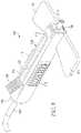
- FIG. 1is a perspective view of an exemplary blood collection assembly in accordance with an embodiment of the present disclosure with a needle advanced.
- FIG. 2is a top cross-sectional view of the blood collection assembly with the needle advanced as shown in FIG. 1 .
- FIG. 3is a side elevational view of the blood collection assembly with the needle advanced as shown in FIG. 1 .
- FIG. 4is an end elevational view of the blood collection assembly with the needle advanced as shown in FIG. 1 .
- FIG. 5is a perspective view of the blood collection assembly of FIG. 1 with the needle retracted.
- FIG. 6is a top cross-sectional view of the blood collection assembly as shown in FIG. 1 with the needle retracted.
- FIG. 7is a side elevational view of the blood collection assembly as shown in FIG. 1 with the needle retracted.
- FIG. 8is an end elevational view of the blood collection assembly as shown in FIG. 1 with the needle retracted.
- the present disclosuredescribes an exemplary blood collection assembly.
- the exemplary blood collection assemblycomprises a hub that contains a needle assembly.
- the hubcomprises a set of wings that are used to balance the blood collection assembly as a needle is injected into a patient's arm.
- a channelWithin a top side of the hub is a channel. Slidably coupled to the channel is a finger-activated actuator.
- the finger-activated actuatoris situated toward the distal end of the hub when the needle is in an advanced position, such as when the needle is inserted into the patient's arm.
- a userslides the finger-activated actuator toward the proximal end of the hub until the needle is completely within the hub.
- the needleis removed from the patient's arm with little risk of accidental sticks.
- a compressed cotton and plastic shieldis inside a compartment that is situated on a top side of the hub.
- the compressed cotton and plastic shieldfalls down between the distal end of the needle and the needle opening in the hub. The cotton absorbs any excess liquid or blood and the plastic protects users from the distal end of the needle ensuring that the needle does not advance.
- FIG. 1is a perspective view of a blood collection assembly 100 in accordance with an embodiment of the present disclosure when a needle 101 is in an advanced position.
- An “advanced position”indicates that the needle is protruding for insertion into a patient's arm (not shown).
- the needle 101protrudes from a plastic lid receptacle 113 to which a safety plastic lid (not shown) is coupled before use of the blood collection assembly 100 .
- the blood collection assembly 100comprises a hub 102 , a needle 101 , and flexible tubing 103 .
- the flexible tubing 103may comprise a clamp (not shown) for clamping the flexible tubing 103 to prohibit blood from fluidically travelling through the tubing.
- the needle 101is inserted in the patient's arm, blood flows through a needle assembly (not shown) that is coupled to the flexible tubing 103 , and the blood flows through the flexible tubing 103 to a reservoir (not shown).
- the blood collection assembly 100further comprises a substantially cuboidal-shaped channel 107 formed in a top surface 114 of the hub 102 .
- the substantially cuboidal-shaped channel 107runs rectilinearly from a distal end 106 to a proximal end 116 of the hub 102 .
- Slidably engaged with the cuboidal-shaped channel 107is a finger-activated actuator 108 , and the finger-activated actuator 108 is fixedly coupled to the needle assembly within the hub 102 , which is described further herein.
- a userinserts the needle 101 in a patient's arm. Blood is collected via the flexible tubing 103 in the reservoir. After the blood is collected, the user places his/her finger on the finger-activated actuator 108 and pulls the finger-activated actuator 108 to the proximal end 116 of the hub 102 . Once the finger-activated actuator 108 has been moved to the proximal end 116 of the hub 102 , the needle 101 is completely inside the hub 102 . Thus, the needle 101 does not pose an accidental stick risk.
- the blood collection assembly 100further comprises wings 110 and 111 .
- the wings 110 and 111are coupled to and extend laterally from the distal end 106 of the hub 102 .
- the wings 110 and 111stabilize the blood collection assembly 100 while the needle 101 is inserted into the patient's arm. Further, the wings 110 and 111 stabilize the blood collection assembly 100 post insertion while blood is being drawn. Additionally, the wings 110 and 111 stabilize the assembly 100 when the finger-activated actuator 108 is actuated.
- the blood collection assembly 100further comprises a compartment 115 .
- the compartment 115houses a compressed cotton and plastic shield (not shown) that is housed in the hub 102 . While the needle 101 is in the advanced position, the compressed cotton and plastic shield rests above the needle 101 . However, when the needle 101 is moved to a retracted position via the finger-activated actuator 108 , the compressed cotton and plastic shield falls between the distal end of the needle 101 and the plastic lid receptacle 113 inside the hub 102 . The compressed cotton absorbs any fluid or blood that might leak from the needle 101 and the plastic shields the needle 101 from advancing through the plastic lid receptacle 113 .
- the blood collection assembly 100further comprises gripper pads 112 and 117 .
- the gripper pads 112 and 117are coupled to or integral with the sides of the hub 102 .
- the gripper pads 112 and 117enable the user to easily grip the blood collection assembly 100 while in use.
- the gripper pads 112 and 117allow the user to easily grasp the blood collection assembly 100 when the user is collecting blood from the patient's arm or when the user is actuating the finger-activated actuator 108 to retract the needle 101 .
- FIG. 2is a top cross-sectional view of the blood collection assembly 100 when the needle 101 is in the advanced position for insertion into a patient's arm. Note that prior to use of the blood collection assembly 100 , a plastic lid (not shown) is coupled to the plastic lid receptacle 113 on the distal end of the hub 102 to protect from accidental sticks. In FIG. 2 , the plastic lid is shown removed from the blood collection assembly 100 , and the needle is exposed.
- gripper pads 112 and 117are shown coupled to or integral with the sides of the hub 102 . As described hereinabove, the gripper pads 112 and 117 enable the user to easily grip the blood collection assembly 100 while in use.
- the wings 110 and 111are shown coupled to the distal end 106 of the hub 102 . As described hereinabove, the wings 110 and 111 stabilize the blood collection assembly 100 while in use.
- the blood collection assembly 100further comprises a needle assembly 200 .
- the needle assemblyis moveably contained within a chamber 211 of the hub 102 .
- the needle assembly 200comprises a tubular member 204 .
- the tubular member 204comprises a cylindrical channel 204 defined by an inner wall 205 .
- the needle assembly 200is fixedly coupled to the needle 101 and the tubing 103 ( FIG. 1 ).
- the finger-activated actuator 108is fixedly coupled to the needle assembly 200 such that when the finger-activated actuator 108 is moved from the distal end 106 to the proximal end 116 of the hub 102 , the needle assembly 200 moves with the finger-activated actuator 108 from the distal end 106 to the proximal end 116 of the hub 102 .
- the needle assembly 200further comprises a substantially rectangular-shaped protrusion 202 .
- the rectangular-shaped protrusion 202rests within a substantially rectangular-shaped indentation 201 in an inside surface 210 of the hub 102 .
- the rectangular-shaped protrusion 202locks into the rectangular-shaped indentation 201 thereby fixing the needle assembly 200 at the proximal end of the hub 102 .
- the needle assembly 200including the needle 101 , can no longer move toward the distal end 106 of the hub 102 . Therefore, users are protected from the needle 101 when the needle assembly 200 is in the retracted position, which is shown with reference to FIG. 6 .
- FIG. 3is a side elevational view of the blood collection assembly 100 when the needle is in the advanced position.
- the needle assembly 200comprises the tubular member 204 .
- the tubular member 204comprises the cylindrical channel 204 defined by the inner wall 205 .
- the needle assembly 200comprises the needle 101 that is fixedly coupled to the tubular member 204 .
- the finger-activated actuator 108is fixedly coupled to the needle assembly 200 such that when the finger-activated actuator 108 is moved from the distal end 106 to the proximal end 116 of the hub 102 , the needle assembly 200 moves with the finger-activated actuator 108 to the proximal end 116 of the hub 102 .
- the blood collection assembly 100further comprises a compressed cotton and plastic shield 301 .
- the compressed cotton and plastic shield 301is situated in the compartment 115 above the needle assembly 200 when the needle assembly 200 is in the advanced position. Note that as will be shown further herein, when the needle assembly 200 is retracted by the finger-activated actuator 108 , the compressed cotton and plastic shield 301 falls downward resting between the distal end of the needle 101 and the receptacle 113 .
- the compressed cotton of the shield 301absorbs any excess liquid or blood from the needle 101 , and the plastic portion of the shield 301 safely ensures that the needle 101 does not advance outwardly through the receptacle 113 .
- the blood collection assembly 100further comprises an angled bottom surface 302 .
- the surface 302is angled at an acute angle ⁇ .
- the angle bottom surface 302levels the blood collection assembly 100 so that when the finger-activated actuator 108 is moved by the user, the blood collection assembly 100 remains stabilized.
- FIG. 4is an end elevational view of the blood collection assembly 100 when the needle assembly 200 is in the advanced position and the needle 101 protrudes from the receptacle 113 . Further, wings 110 and 111 protrude laterally from the hub 102 for stabilization of the blood collection assembly 100 .
- the blood collection assembly 100comprises the compartment 115 that protrudes from an upper surface 400 of the hub 102 . While the needle assembly 200 is in the advanced position, the compressed cotton and plastic shield 301 is situated within the compartment 115 above the needle 101 . As will be shown further herein, when the needle assembly 200 is retracted, the compressed cotton and plastic shield 301 falls downward and rests between the distal end of the needle 101 and the receptacle 113 .
- FIG. 5is a perspective view of the blood collection assembly 100 in accordance with an embodiment of the present disclosure when the needle 101 is in a retracted position.
- a “retracted position”indicates that the needle has been moved from the patient's arm and is housed within the hub 102 .
- the needle 101no longer protrudes from the plastic lid receptacle 113 .
- the blood collection assembly 100further comprises the substantially cuboidal-shaped channel 107 formed in the top surface 114 of the hub 102 .
- the substantially cuboidal-shaped channel 107runs rectilinearly from the distal end 106 to a proximal end 116 of the hub 102 .
- Slidably engaged with the cuboidal-shaped channel 107is the finger-activated actuator 108 , and the finger-activated actuator 108 is fixedly coupled to the needle assembly 200 ( FIG. 2 ) within the hub 102 .
- a userinserts the needle 101 in a patient's arm. Blood is collected via the flexible tubing 103 in the reservoir. After the blood is collected, the user places his/her finger on the finger-activated actuator 108 and pulls the finger-activated actuator 108 to the proximal end 116 of the hub 102 . Once the finger-activated actuator 108 has been moved to the proximal end 116 of the hub 102 , the needle 101 is completely inside the hub 102 . Thus, the needle 101 no longer poses an accidental stick risk.
- the blood collection assembly 100further comprises the wings 110 and 111 .
- the wings 110 and 111are coupled to and extend laterally from the distal end 106 of the hub 102 .
- the wings 110 and 111stabilize the blood collection assembly 100 while the needle 101 is inserted into the patient's arm. Further, the wings 110 and 111 stabilize the blood collection assembly 100 post insertion while blood is being drawn.
- the blood collection assembly 100further comprises the compartment 115 .
- the compartment 115houses the compressed cotton and plastic shield 301 ( FIG. 3 ) that is housed in the hub 102 . While the needle 101 is in the advanced position, the compressed cotton and plastic shield 301 rests above the needle 101 . However, when the needle 101 is moved to the retracted position via the finger-activated actuator 108 , the compressed cotton and plastic shield 301 falls downwardly between the distal end of the needle 101 and the plastic lid receptacle 113 inside the hub 102 . The compressed cotton absorbs any fluid or blood that might leak from the needle 101 , and the plastic shields the needle 101 from advancing through the plastic lid receptacle 113 .
- the blood collection assembly 100further comprises the gripper pads 112 and 117 .
- the gripper pads 112 and 117are coupled to or integral with the sides of the hub 102 .
- the gripper pads 112 and 117enable the user to easily grip the blood collection assembly 100 while in use.
- FIG. 6is a top cross-sectional view of the blood collection assembly 100 when the needle 101 is in the retracted position. Note that prior to use of the blood collection assembly 100 , a plastic lid (not shown) is coupled to the plastic lid receptacle 113 on the distal end of the hub 102 to protect from accidental sticks. In FIG. 6 , the plastic lid is shown removed from the blood collection assembly 100 , and the needle is retracted.
- gripper pads 112 and 117are shown coupled to or integral with the sides of the hub 102 . As described hereinabove, the gripper pads 112 and 117 enable the user to easily grip the blood collection assembly 100 while in use.
- the wings 110 and 111are shown coupled to the distal end 106 of the hub 102 . As described hereinabove, the wings 110 and 111 stabilize the blood collection assembly 100 while in use.
- the blood collection assembly 100further comprises the needle assembly 200 .
- the needle assembly 200is moveably contained within the chamber 211 of the hub 102 .
- the needle assembly 200comprises the tubular member 204 .
- the tubular member 204comprises the cylindrical channel 204 defined by the inner wall 205 .
- the needle assembly 200is fixedly coupled to the needle 101 and the tubing 103 ( FIG. 5 ).
- the finger-activated actuator 108is fixedly coupled to the needle assembly 200 such that when the finger-activated actuator 108 is moved from the distal end 106 to the proximal end 116 of the hub 102 , the needle assembly 200 moves with the finger-activated actuator 108 .
- the needle assembly 200further comprises the substantially rectangular-shaped protrusion 202 .
- the rectangular-shaped protrusion 202rests within the substantially rectangular-shaped indentation 201 within an inside surface 210 of the hub 102 .
- the rectangular-shaped protrusion 202locks into the rectangular-shaped indentation 201 thereby fixing the needle assembly 200 at the proximal end of the hub 102 .
- the needle assembly 200including the needle 101 , can no longer move toward the distal end 106 of the hub 102 . Therefore, users are protected from the needle 101 when the needle assembly 200 is in the retracted position.
- the compressed cotton and plastic shield 301falls downwardly.
- the compressed cotton and plastic shield 301rests between the distal end of the needle 101 and the receptacle 113 .
- the compressed cotton portion of the shieldabsorbs any fluid or blood that escapes the needle 101 .
- the plastic portion of the shield 301safely ensures that the needle 101 does not advance outwardly through the receptacle 113 posing an accidental stick risk.
- FIG. 7is a side elevational view of the blood collection assembly 100 when the needle is in the retracted position.
- the needle assembly 200comprises the needle 101 .
- the finger-activated actuator 108is fixedly coupled to the needle assembly 200 such that when the finger-activated actuator 108 is moved from the distal end 106 to the proximal end 116 of the hub 102 , the needle assembly 200 moves with the finger-activated actuator 108 .
- the blood collection assembly 100further comprises the compressed cotton and plastic shield 301 .
- the compressed cotton and plastic shield 301When in the retracted position, the compressed cotton and plastic shield 301 is situated between the distal end of the needle 101 and the receptacle 113 .
- the compressed cotton of the shield 301absorbs any excess liquid or blood from the needle 101 , and the plastic portion of the shield 301 safely ensures that the needle 101 does not advance outwardly through the receptacle 113 .
- the blood collection assembly 100further comprises the angled bottom surface 302 .
- the surface 302is angled at an acute angle ⁇ .
- the angle bottom surface 302levels the blood collection assembly 100 so that when the finger-activated actuator 108 is moved by the user, the blood collection assembly 100 remains stabilized.
- FIG. 8is an end elevational view of the blood collection assembly 100 when the needle assembly 200 is in the retracted position and the needle 101 ( FIG. 6 ) is within the hub 102 .
- the blood collection assembly 100comprises the compartment 115 that protrudes from an upper surface 400 of the hub 102 and houses the compressed cotton and plastic shield 301 .
- the compressed cotton and plastic shield 301falls downward and rests between the distal end of the needle 101 and the receptacle 113 .
Landscapes
- Health & Medical Sciences (AREA)
- Life Sciences & Earth Sciences (AREA)
- Engineering & Computer Science (AREA)
- Heart & Thoracic Surgery (AREA)
- Molecular Biology (AREA)
- Pathology (AREA)
- Physics & Mathematics (AREA)
- Biomedical Technology (AREA)
- Hematology (AREA)
- Medical Informatics (AREA)
- Biophysics (AREA)
- Surgery (AREA)
- Animal Behavior & Ethology (AREA)
- General Health & Medical Sciences (AREA)
- Public Health (AREA)
- Veterinary Medicine (AREA)
- Manufacturing & Machinery (AREA)
- Measurement Of The Respiration, Hearing Ability, Form, And Blood Characteristics Of Living Organisms (AREA)
Abstract
Description
Claims (19)
Priority Applications (4)
| Application Number | Priority Date | Filing Date | Title |
|---|---|---|---|
| US16/390,499US11529080B2 (en) | 2019-04-22 | 2019-04-22 | Blood collection assembly |
| CR20240210ACR20240210A (en) | 2019-04-22 | 2021-10-20 | Blood collection assembly |
| US18/062,432US20240180464A1 (en) | 2019-04-22 | 2022-12-06 | Blood collection assembly |
| US18/641,174US20240260868A1 (en) | 2019-04-22 | 2024-04-19 | Blood collection assembly |
Applications Claiming Priority (1)
| Application Number | Priority Date | Filing Date | Title |
|---|---|---|---|
| US16/390,499US11529080B2 (en) | 2019-04-22 | 2019-04-22 | Blood collection assembly |
Related Child Applications (1)
| Application Number | Title | Priority Date | Filing Date |
|---|---|---|---|
| US18/062,432ContinuationUS20240180464A1 (en) | 2019-04-22 | 2022-12-06 | Blood collection assembly |
Publications (2)
| Publication Number | Publication Date |
|---|---|
| US20200330015A1 US20200330015A1 (en) | 2020-10-22 |
| US11529080B2true US11529080B2 (en) | 2022-12-20 |
Family
ID=72829572
Family Applications (2)
| Application Number | Title | Priority Date | Filing Date |
|---|---|---|---|
| US16/390,499Active2041-05-11US11529080B2 (en) | 2019-04-22 | 2019-04-22 | Blood collection assembly |
| US18/062,432PendingUS20240180464A1 (en) | 2019-04-22 | 2022-12-06 | Blood collection assembly |
Family Applications After (1)
| Application Number | Title | Priority Date | Filing Date |
|---|---|---|---|
| US18/062,432PendingUS20240180464A1 (en) | 2019-04-22 | 2022-12-06 | Blood collection assembly |
Country Status (1)
| Country | Link |
|---|---|
| US (2) | US11529080B2 (en) |
Families Citing this family (3)
| Publication number | Priority date | Publication date | Assignee | Title |
|---|---|---|---|---|
| WO2023069092A1 (en)* | 2021-10-20 | 2023-04-27 | The Monarch Company | Blood collection assembly |
| CN213252024U (en)* | 2019-09-10 | 2021-05-25 | 贝克顿·迪金森公司 | Vascular access system and clamping device |
| WO2024172839A1 (en)* | 2023-02-13 | 2024-08-22 | The Monarch Company, Llc | Blood collection assembly |
Citations (34)
| Publication number | Priority date | Publication date | Assignee | Title |
|---|---|---|---|---|
| US3734080A (en)* | 1969-06-12 | 1973-05-22 | Johnson & Johnson | Blood collecting shut-off valve |
| US4676783A (en) | 1985-09-03 | 1987-06-30 | The University Of Virginia Alumni Patents Foundation | Retractable safety needle |
| US4747831A (en) | 1987-04-29 | 1988-05-31 | Phase Medical, Inc. | Cannula insertion set with safety retracting needle |
| US4781692A (en) | 1985-09-03 | 1988-11-01 | The University Of Virginia Alumni Patents Foundation | Retractable safety needles |
| US5085639A (en)* | 1988-03-01 | 1992-02-04 | Ryan Medical, Inc. | Safety winged needle medical devices |
| US5088982A (en) | 1988-03-01 | 1992-02-18 | Ryan Medical, Inc. | Safety winged needle medical devices |
| US5120320A (en) | 1991-02-13 | 1992-06-09 | Becton, Dickinson And Company | I.V. infusion or blood collection assembly with automatic safety feature |
| US5176655A (en) | 1990-11-08 | 1993-01-05 | Mbo Laboratories, Inc. | Disposable medical needle and catheter placement assembly having full safety enclosure means |
| US5498241A (en) | 1994-12-08 | 1996-03-12 | Abbott Laboratories | Winged needle assembly with protective member |
| US5549571A (en) | 1995-04-18 | 1996-08-27 | Sak; Robert F. | Butterfly assembly with retractable needle cannula |
| US5573512A (en) | 1990-09-05 | 1996-11-12 | Advanced Protective Injection Systems B.V. | Infusion or transfusion needle assembly |
| US5746215A (en) | 1996-11-01 | 1998-05-05 | U.S. Medical Instruments, Inc. | IV infusion or collection device with extendable and retractable needle |
| US5779679A (en) | 1997-04-18 | 1998-07-14 | Shaw; Thomas J. | Winged IV set with retractable needle |
| US5928199A (en) | 1996-09-20 | 1999-07-27 | Nissho Corporation | Winged needle assembly |
| US5951525A (en) | 1998-02-10 | 1999-09-14 | Specialized Health Products, Inc. | Manual safety medical needle apparatus and methods |
| CA2356199A1 (en)* | 1998-12-22 | 2000-06-29 | Owais Mohammad | Retractable hypodermic needle assembly and method of making the same |
| US6210371B1 (en) | 1999-03-30 | 2001-04-03 | Retractable Technologies, Inc. | Winged I.V. set |
| CA2384546A1 (en)* | 1999-09-27 | 2001-04-05 | Jms Co., Ltd. | Winged injection needle having needle covering means |
| US6309376B1 (en) | 1999-10-07 | 2001-10-30 | Sims Portex, Inc. | Safety device for intravenous infusion needles |
| US20030181874A1 (en) | 2002-03-20 | 2003-09-25 | Becton, Dickinson And Company | Blood collection device |
| US6673047B2 (en) | 2001-01-05 | 2004-01-06 | Becton, Dickinson And Company | Blood collection set |
| US6743186B2 (en) | 2001-01-05 | 2004-06-01 | Becton, Dickinson And Company | Blood collection assembly |
| CN1515329A (en)* | 2003-01-08 | 2004-07-28 | 汪贤宗 | Disposable safety needle cover device |
| US6773419B2 (en) | 2001-01-05 | 2004-08-10 | Jamieson William Maclean Crawford | Blood collection set |
| US6835190B2 (en) | 2002-04-17 | 2004-12-28 | Smiths Medical Asd, Inc. | Retractable safety infusion needle |
| US20050119627A1 (en) | 2003-12-01 | 2005-06-02 | Becton, Dickinson And Company | Selectively passive forward shielding medical needle device |
| US6918891B2 (en) | 2002-03-21 | 2005-07-19 | Becton Dickinson Co | Safety device |
| US7018344B2 (en) | 2003-01-21 | 2006-03-28 | Becton, Dickinson And Company | Retractable needle shielding device |
| US7144387B2 (en) | 2003-05-09 | 2006-12-05 | Visual Connections | Butterfly needle with passive guard |
| US8308691B2 (en)* | 2006-11-03 | 2012-11-13 | B. Braun Melsungen Ag | Catheter assembly and components thereof |
| US8469927B2 (en) | 2008-06-10 | 2013-06-25 | Retractable Technologies, Inc. | Fluid flow control device with retractable cannula |
| US20130289524A1 (en)* | 2004-07-01 | 2013-10-31 | Becton, Dickinson And Company | Passively Shielding Needle Device |
| USD751691S1 (en) | 2014-02-12 | 2016-03-15 | Retractable Technologies, Inc. | Housing for blood collection set |
| EP3024514B1 (en) | 2013-07-22 | 2017-06-14 | Delta Med S.P.A. Unipersonale | Butterfly needle with a protective device |
- 2019
- 2019-04-22USUS16/390,499patent/US11529080B2/enactiveActive
- 2022
- 2022-12-06USUS18/062,432patent/US20240180464A1/enactivePending
Patent Citations (34)
| Publication number | Priority date | Publication date | Assignee | Title |
|---|---|---|---|---|
| US3734080A (en)* | 1969-06-12 | 1973-05-22 | Johnson & Johnson | Blood collecting shut-off valve |
| US4676783A (en) | 1985-09-03 | 1987-06-30 | The University Of Virginia Alumni Patents Foundation | Retractable safety needle |
| US4781692A (en) | 1985-09-03 | 1988-11-01 | The University Of Virginia Alumni Patents Foundation | Retractable safety needles |
| US4747831A (en) | 1987-04-29 | 1988-05-31 | Phase Medical, Inc. | Cannula insertion set with safety retracting needle |
| US5085639A (en)* | 1988-03-01 | 1992-02-04 | Ryan Medical, Inc. | Safety winged needle medical devices |
| US5088982A (en) | 1988-03-01 | 1992-02-18 | Ryan Medical, Inc. | Safety winged needle medical devices |
| US5573512A (en) | 1990-09-05 | 1996-11-12 | Advanced Protective Injection Systems B.V. | Infusion or transfusion needle assembly |
| US5176655A (en) | 1990-11-08 | 1993-01-05 | Mbo Laboratories, Inc. | Disposable medical needle and catheter placement assembly having full safety enclosure means |
| US5120320A (en) | 1991-02-13 | 1992-06-09 | Becton, Dickinson And Company | I.V. infusion or blood collection assembly with automatic safety feature |
| US5498241A (en) | 1994-12-08 | 1996-03-12 | Abbott Laboratories | Winged needle assembly with protective member |
| US5549571A (en) | 1995-04-18 | 1996-08-27 | Sak; Robert F. | Butterfly assembly with retractable needle cannula |
| US5928199A (en) | 1996-09-20 | 1999-07-27 | Nissho Corporation | Winged needle assembly |
| US5746215A (en) | 1996-11-01 | 1998-05-05 | U.S. Medical Instruments, Inc. | IV infusion or collection device with extendable and retractable needle |
| US5779679A (en) | 1997-04-18 | 1998-07-14 | Shaw; Thomas J. | Winged IV set with retractable needle |
| US5951525A (en) | 1998-02-10 | 1999-09-14 | Specialized Health Products, Inc. | Manual safety medical needle apparatus and methods |
| CA2356199A1 (en)* | 1998-12-22 | 2000-06-29 | Owais Mohammad | Retractable hypodermic needle assembly and method of making the same |
| US6210371B1 (en) | 1999-03-30 | 2001-04-03 | Retractable Technologies, Inc. | Winged I.V. set |
| CA2384546A1 (en)* | 1999-09-27 | 2001-04-05 | Jms Co., Ltd. | Winged injection needle having needle covering means |
| US6309376B1 (en) | 1999-10-07 | 2001-10-30 | Sims Portex, Inc. | Safety device for intravenous infusion needles |
| US6673047B2 (en) | 2001-01-05 | 2004-01-06 | Becton, Dickinson And Company | Blood collection set |
| US6743186B2 (en) | 2001-01-05 | 2004-06-01 | Becton, Dickinson And Company | Blood collection assembly |
| US6773419B2 (en) | 2001-01-05 | 2004-08-10 | Jamieson William Maclean Crawford | Blood collection set |
| US20030181874A1 (en) | 2002-03-20 | 2003-09-25 | Becton, Dickinson And Company | Blood collection device |
| US6918891B2 (en) | 2002-03-21 | 2005-07-19 | Becton Dickinson Co | Safety device |
| US6835190B2 (en) | 2002-04-17 | 2004-12-28 | Smiths Medical Asd, Inc. | Retractable safety infusion needle |
| CN1515329A (en)* | 2003-01-08 | 2004-07-28 | 汪贤宗 | Disposable safety needle cover device |
| US7018344B2 (en) | 2003-01-21 | 2006-03-28 | Becton, Dickinson And Company | Retractable needle shielding device |
| US7144387B2 (en) | 2003-05-09 | 2006-12-05 | Visual Connections | Butterfly needle with passive guard |
| US20050119627A1 (en) | 2003-12-01 | 2005-06-02 | Becton, Dickinson And Company | Selectively passive forward shielding medical needle device |
| US20130289524A1 (en)* | 2004-07-01 | 2013-10-31 | Becton, Dickinson And Company | Passively Shielding Needle Device |
| US8308691B2 (en)* | 2006-11-03 | 2012-11-13 | B. Braun Melsungen Ag | Catheter assembly and components thereof |
| US8469927B2 (en) | 2008-06-10 | 2013-06-25 | Retractable Technologies, Inc. | Fluid flow control device with retractable cannula |
| EP3024514B1 (en) | 2013-07-22 | 2017-06-14 | Delta Med S.P.A. Unipersonale | Butterfly needle with a protective device |
| USD751691S1 (en) | 2014-02-12 | 2016-03-15 | Retractable Technologies, Inc. | Housing for blood collection set |
Also Published As
| Publication number | Publication date |
|---|---|
| US20200330015A1 (en) | 2020-10-22 |
| US20240180464A1 (en) | 2024-06-06 |
Similar Documents
| Publication | Publication Date | Title |
|---|---|---|
| US20240180464A1 (en) | Blood collection assembly | |
| US5067490A (en) | Single use, safety blood collecting device | |
| CN1636607B (en) | Passive safety device for needle of blood collection set | |
| US6855130B2 (en) | Passive safety device for needle of IV infusion or blood collection set | |
| AU2011306445B2 (en) | Needle tip guard for intravenous catheter assembly | |
| US5037402A (en) | Dual-chamber safety syringe | |
| US20060189934A1 (en) | Needle tip guard for percutaneous entry needles | |
| CN1124110C (en) | Disposal medical thrust device | |
| US7198617B2 (en) | Passively guarded, fillable injection syringe | |
| US4951685A (en) | Blood drawing system | |
| EP3517154B1 (en) | Passive double drive member activated safety blood collection device | |
| CN1556717A (en) | blood collection device | |
| EP0595507B1 (en) | Needle stopper and needle removal device | |
| CA2931752C (en) | Blood collection device with double pivot shields | |
| TWI798399B (en) | Intravenous catheter introducer for medical use | |
| EP0578367A1 (en) | Catheter with needle guard and extended flash chamber | |
| US20240260868A1 (en) | Blood collection assembly | |
| AU2021469659A1 (en) | Blood collection assembly | |
| WO2008121094A1 (en) | Apparatus for locking concentric components in alignment |
Legal Events
| Date | Code | Title | Description |
|---|---|---|---|
| FEPP | Fee payment procedure | Free format text:ENTITY STATUS SET TO UNDISCOUNTED (ORIGINAL EVENT CODE: BIG.); ENTITY STATUS OF PATENT OWNER: SMALL ENTITY | |
| FEPP | Fee payment procedure | Free format text:ENTITY STATUS SET TO SMALL (ORIGINAL EVENT CODE: SMAL); ENTITY STATUS OF PATENT OWNER: SMALL ENTITY | |
| STPP | Information on status: patent application and granting procedure in general | Free format text:NON FINAL ACTION MAILED | |
| STPP | Information on status: patent application and granting procedure in general | Free format text:RESPONSE TO NON-FINAL OFFICE ACTION ENTERED AND FORWARDED TO EXAMINER | |
| STPP | Information on status: patent application and granting procedure in general | Free format text:FINAL REJECTION MAILED | |
| AS | Assignment | Owner name:THE MONARCH COMPANY LLC, ALABAMA Free format text:ASSIGNMENT OF ASSIGNORS INTEREST;ASSIGNOR:HMG ENTERPRISES LLC;REEL/FRAME:060451/0965 Effective date:20210603 Owner name:HMG ENTERPRISES LLC, ALABAMA Free format text:ASSIGNMENT OF ASSIGNORS INTEREST;ASSIGNOR:PRICE, JAMES;REEL/FRAME:060451/0957 Effective date:20190417 | |
| STPP | Information on status: patent application and granting procedure in general | Free format text:DOCKETED NEW CASE - READY FOR EXAMINATION | |
| STPP | Information on status: patent application and granting procedure in general | Free format text:NOTICE OF ALLOWANCE MAILED -- APPLICATION RECEIVED IN OFFICE OF PUBLICATIONS | |
| AS | Assignment | Owner name:THE MONARCH COMPANY, LLC, ALABAMA Free format text:ASSIGNMENT OF ASSIGNORS INTEREST;ASSIGNORS:TRAWICK, JONATHAN;SEMMANN, CLINT;REEL/FRAME:061038/0600 Effective date:20220908 | |
| STPP | Information on status: patent application and granting procedure in general | Free format text:PUBLICATIONS -- ISSUE FEE PAYMENT VERIFIED | |
| STCF | Information on status: patent grant | Free format text:PATENTED CASE | |
| CC | Certificate of correction |