US11529042B2 - Stereo imaging miniature endoscope with single imaging and conjugated multi-bandpass filters - Google Patents
Stereo imaging miniature endoscope with single imaging and conjugated multi-bandpass filtersDownload PDFInfo
- Publication number
- US11529042B2 US11529042B2US15/942,936US201815942936AUS11529042B2US 11529042 B2US11529042 B2US 11529042B2US 201815942936 AUS201815942936 AUS 201815942936AUS 11529042 B2US11529042 B2US 11529042B2
- Authority
- US
- United States
- Prior art keywords
- image
- endoscope
- images
- detector
- light
- Prior art date
- Legal status (The legal status is an assumption and is not a legal conclusion. Google has not performed a legal analysis and makes no representation as to the accuracy of the status listed.)
- Active, expires
Links
Images


Classifications
- A—HUMAN NECESSITIES
- A61—MEDICAL OR VETERINARY SCIENCE; HYGIENE
- A61B—DIAGNOSIS; SURGERY; IDENTIFICATION
- A61B1/00—Instruments for performing medical examinations of the interior of cavities or tubes of the body by visual or photographical inspection, e.g. endoscopes; Illuminating arrangements therefor
- A61B1/00163—Optical arrangements
- A61B1/00193—Optical arrangements adapted for stereoscopic vision
- A—HUMAN NECESSITIES
- A61—MEDICAL OR VETERINARY SCIENCE; HYGIENE
- A61B—DIAGNOSIS; SURGERY; IDENTIFICATION
- A61B1/00—Instruments for performing medical examinations of the interior of cavities or tubes of the body by visual or photographical inspection, e.g. endoscopes; Illuminating arrangements therefor
- A61B1/00163—Optical arrangements
- A61B1/00194—Optical arrangements adapted for three-dimensional imaging
- A—HUMAN NECESSITIES
- A61—MEDICAL OR VETERINARY SCIENCE; HYGIENE
- A61B—DIAGNOSIS; SURGERY; IDENTIFICATION
- A61B1/00—Instruments for performing medical examinations of the interior of cavities or tubes of the body by visual or photographical inspection, e.g. endoscopes; Illuminating arrangements therefor
- A61B1/012—Instruments for performing medical examinations of the interior of cavities or tubes of the body by visual or photographical inspection, e.g. endoscopes; Illuminating arrangements therefor characterised by internal passages or accessories therefor
- A61B1/018—Instruments for performing medical examinations of the interior of cavities or tubes of the body by visual or photographical inspection, e.g. endoscopes; Illuminating arrangements therefor characterised by internal passages or accessories therefor for receiving instruments
- A—HUMAN NECESSITIES
- A61—MEDICAL OR VETERINARY SCIENCE; HYGIENE
- A61B—DIAGNOSIS; SURGERY; IDENTIFICATION
- A61B1/00—Instruments for performing medical examinations of the interior of cavities or tubes of the body by visual or photographical inspection, e.g. endoscopes; Illuminating arrangements therefor
- A61B1/04—Instruments for performing medical examinations of the interior of cavities or tubes of the body by visual or photographical inspection, e.g. endoscopes; Illuminating arrangements therefor combined with photographic or television appliances
- A61B1/045—Control thereof
- A—HUMAN NECESSITIES
- A61—MEDICAL OR VETERINARY SCIENCE; HYGIENE
- A61B—DIAGNOSIS; SURGERY; IDENTIFICATION
- A61B1/00—Instruments for performing medical examinations of the interior of cavities or tubes of the body by visual or photographical inspection, e.g. endoscopes; Illuminating arrangements therefor
- A61B1/04—Instruments for performing medical examinations of the interior of cavities or tubes of the body by visual or photographical inspection, e.g. endoscopes; Illuminating arrangements therefor combined with photographic or television appliances
- A61B1/05—Instruments for performing medical examinations of the interior of cavities or tubes of the body by visual or photographical inspection, e.g. endoscopes; Illuminating arrangements therefor combined with photographic or television appliances characterised by the image sensor, e.g. camera, being in the distal end portion
- A—HUMAN NECESSITIES
- A61—MEDICAL OR VETERINARY SCIENCE; HYGIENE
- A61B—DIAGNOSIS; SURGERY; IDENTIFICATION
- A61B1/00—Instruments for performing medical examinations of the interior of cavities or tubes of the body by visual or photographical inspection, e.g. endoscopes; Illuminating arrangements therefor
- A61B1/06—Instruments for performing medical examinations of the interior of cavities or tubes of the body by visual or photographical inspection, e.g. endoscopes; Illuminating arrangements therefor with illuminating arrangements
- A61B1/0638—Instruments for performing medical examinations of the interior of cavities or tubes of the body by visual or photographical inspection, e.g. endoscopes; Illuminating arrangements therefor with illuminating arrangements providing two or more wavelengths
- A—HUMAN NECESSITIES
- A61—MEDICAL OR VETERINARY SCIENCE; HYGIENE
- A61B—DIAGNOSIS; SURGERY; IDENTIFICATION
- A61B1/00—Instruments for performing medical examinations of the interior of cavities or tubes of the body by visual or photographical inspection, e.g. endoscopes; Illuminating arrangements therefor
- A61B1/06—Instruments for performing medical examinations of the interior of cavities or tubes of the body by visual or photographical inspection, e.g. endoscopes; Illuminating arrangements therefor with illuminating arrangements
- A61B1/0646—Instruments for performing medical examinations of the interior of cavities or tubes of the body by visual or photographical inspection, e.g. endoscopes; Illuminating arrangements therefor with illuminating arrangements with illumination filters
- A—HUMAN NECESSITIES
- A61—MEDICAL OR VETERINARY SCIENCE; HYGIENE
- A61B—DIAGNOSIS; SURGERY; IDENTIFICATION
- A61B1/00—Instruments for performing medical examinations of the interior of cavities or tubes of the body by visual or photographical inspection, e.g. endoscopes; Illuminating arrangements therefor
- A61B1/06—Instruments for performing medical examinations of the interior of cavities or tubes of the body by visual or photographical inspection, e.g. endoscopes; Illuminating arrangements therefor with illuminating arrangements
- A61B1/0655—Control therefor
- H—ELECTRICITY
- H04—ELECTRIC COMMUNICATION TECHNIQUE
- H04N—PICTORIAL COMMUNICATION, e.g. TELEVISION
- H04N13/00—Stereoscopic video systems; Multi-view video systems; Details thereof
- H04N13/20—Image signal generators
- H04N13/204—Image signal generators using stereoscopic image cameras
- H04N13/207—Image signal generators using stereoscopic image cameras using a single 2D image sensor
- H04N13/211—Image signal generators using stereoscopic image cameras using a single 2D image sensor using temporal multiplexing
- H—ELECTRICITY
- H04—ELECTRIC COMMUNICATION TECHNIQUE
- H04N—PICTORIAL COMMUNICATION, e.g. TELEVISION
- H04N13/00—Stereoscopic video systems; Multi-view video systems; Details thereof
- H04N13/20—Image signal generators
- H04N13/204—Image signal generators using stereoscopic image cameras
- H04N13/207—Image signal generators using stereoscopic image cameras using a single 2D image sensor
- H04N13/214—Image signal generators using stereoscopic image cameras using a single 2D image sensor using spectral multiplexing
- H—ELECTRICITY
- H04—ELECTRIC COMMUNICATION TECHNIQUE
- H04N—PICTORIAL COMMUNICATION, e.g. TELEVISION
- H04N13/00—Stereoscopic video systems; Multi-view video systems; Details thereof
- H04N13/20—Image signal generators
- H04N13/204—Image signal generators using stereoscopic image cameras
- H04N13/254—Image signal generators using stereoscopic image cameras in combination with electromagnetic radiation sources for illuminating objects
- H—ELECTRICITY
- H04—ELECTRIC COMMUNICATION TECHNIQUE
- H04N—PICTORIAL COMMUNICATION, e.g. TELEVISION
- H04N13/00—Stereoscopic video systems; Multi-view video systems; Details thereof
- H04N13/20—Image signal generators
- H04N13/257—Colour aspects
- A—HUMAN NECESSITIES
- A61—MEDICAL OR VETERINARY SCIENCE; HYGIENE
- A61B—DIAGNOSIS; SURGERY; IDENTIFICATION
- A61B1/00—Instruments for performing medical examinations of the interior of cavities or tubes of the body by visual or photographical inspection, e.g. endoscopes; Illuminating arrangements therefor
- A61B1/00163—Optical arrangements
- A61B1/00174—Optical arrangements characterised by the viewing angles
- A61B1/00183—Optical arrangements characterised by the viewing angles for variable viewing angles
- A—HUMAN NECESSITIES
- A61—MEDICAL OR VETERINARY SCIENCE; HYGIENE
- A61B—DIAGNOSIS; SURGERY; IDENTIFICATION
- A61B1/00—Instruments for performing medical examinations of the interior of cavities or tubes of the body by visual or photographical inspection, e.g. endoscopes; Illuminating arrangements therefor
- A61B1/00163—Optical arrangements
- A61B1/00188—Optical arrangements with focusing or zooming features
- A—HUMAN NECESSITIES
- A61—MEDICAL OR VETERINARY SCIENCE; HYGIENE
- A61B—DIAGNOSIS; SURGERY; IDENTIFICATION
- A61B1/00—Instruments for performing medical examinations of the interior of cavities or tubes of the body by visual or photographical inspection, e.g. endoscopes; Illuminating arrangements therefor
- A61B1/06—Instruments for performing medical examinations of the interior of cavities or tubes of the body by visual or photographical inspection, e.g. endoscopes; Illuminating arrangements therefor with illuminating arrangements
- A61B1/0607—Instruments for performing medical examinations of the interior of cavities or tubes of the body by visual or photographical inspection, e.g. endoscopes; Illuminating arrangements therefor with illuminating arrangements for annular illumination
- A—HUMAN NECESSITIES
- A61—MEDICAL OR VETERINARY SCIENCE; HYGIENE
- A61B—DIAGNOSIS; SURGERY; IDENTIFICATION
- A61B1/00—Instruments for performing medical examinations of the interior of cavities or tubes of the body by visual or photographical inspection, e.g. endoscopes; Illuminating arrangements therefor
- A61B1/06—Instruments for performing medical examinations of the interior of cavities or tubes of the body by visual or photographical inspection, e.g. endoscopes; Illuminating arrangements therefor with illuminating arrangements
- A61B1/0661—Endoscope light sources
- A61B1/0684—Endoscope light sources using light emitting diodes [LED]
Definitions
- the present systemrelates to at least one of a system, method, user interface (UI), and apparatus for providing stereoscopic images and, more particularly, to small-diameter stereoscopic endoscopes for minimally invasive surgery (MIS) as well as to micro-robotic stereoscopic imagers for providing images for space exploration.
- UIuser interface
- MISminimally invasive surgery
- Stereoscopic vision imagingis a well known technology and has been used effectively to provide depth perception to displayed images.
- Stereoscopic imaging devicesoften use a three-dimensional camera to capture images and render three-dimensional (3D) images which may be viewed with realistic depth using a 3D-image-rendering device such as a 3D display.
- 3D-image-rendering devicesuch as a 3D display.
- Such realismis of great importance when performing MIS surgery as minimizes surgical errors and achieves high efficiency during a MIS procedure.
- physical injury due to incisions at a surgical siteis minimized using incisions are typically about 4 mm in across.
- conventional stereoscopic imaging devicesare often bulky as they require two cameras placed side by side which increases the size of the imaging device.
- conventional imaging devicese.g., cameras, etc.
- the present systemdiscloses a system, method, apparatus, and computer program portion (hereinafter each of which may be referred to as system unless the context indicates otherwise) suitable to provide stereoscopic images in an MIS and/or space environment. Accordingly, the present system discloses a small-diameter high-definition stereoscopic endoscope or boroscope (hereinafter commonly called an endoscope) which may have diameter which is less than 4 mm, such as 1-4 mm including any sizes therebetween, such as 3-4 mm, 2-4 mm, 2-3 mm, etc. However, other ranges are also envisioned.
- a micro-robotic stereoscopic imaging systemsuitable for spacecraft which can provide stereoscopic images using a stereoscopic imaging apparatus which may be robotically manipulated and suitable for space exploration.
- a stereoscopic imaging devicewhich uses a single Focal Plane Array (FPA) to capture image information related to right and left fields of view and can provide high definition (e.g., 1000 ⁇ 1000 pixel resolution) images.
- FPAFocal Plane Array
- the present systemsinclude stereoscopic endoscopes with Conjugated Multi-Bandpass Filters (CMBFs) covering right and left pupils which may be formed by a single lens having right and left pupil portions, or two dedicated lenses, one lens for the right pupil and one lens for the left pupil.
- CMBFsConjugated Multi-Bandpass Filters
- the endoscopesmay have a single bore or dual bores, wherein in the case of a dual bore endoscope, two lenses are provided, one lens in each bore for use as a right and left pupils.
- the single bore endoscopemay have one or two lenses.
- conjugated multi-bandpass filters covering right and left pupils of the single objective lensis less complex and less costly, and provides for a smaller endoscope as compared to the dual bore endoscope, and thus allows for further miniaturization.
- using conjugated multi-bandpass filters covering right and left pupilsallows for desired color(s) to pass through the filters while blocking other colors. This is achieved without active shutters, such as without switchable liquid crystal (LC) shutter or mechanical shutters that open or close or move in one direction or another to close one pupil while the other pupil is open.
- LC switchesmay be used in front of the pupils and controlled (such as by a processor) to selectively switch on only one pupil at time.
- a mechanical shuttermay be used and moved back and forth to open one pupil while blocking the other pupil.
- Conjugated multi-bandpass filtersautomatically block undesired light color from entering a pupil provide several advantages, such as not requiring energy needed in LC shutters, and not require moving parts used in mechanical shutters. Accordingly, energy consumption and failure are reduced and reliability increased while producing high definition images in a small area by multispectral imaging.
- the CMBFcreates two viewpoints in a single lens.
- the filtersare called “conjugated” because the spectral passbands of one filter do not overlap with those of the other filters; instead the spectral passbands are interdigitated (see FIG. 9 ), where each color band is divided into right and left colors, such right red R R , left red R L , right green G R , left green G L , right blue B R and left blue B L .
- circular CMBFsare used which are each cut in half and joined with the conjugated other half to form the CMBF full circle covering a portion or the entire single objective lens and providing right and left pupil portions, so that the full circle CMBF can fit along with other circular optical elements, such as over a circular single objective lens.
- the one half CMBFWhen a light band matching to a bandpass of one CMBF is illuminated, the one half CMBF passes a light band, but the other half CMBF stops the same light band. A region of interest is illuminated using a series of light bands matching to the passbands of the CMBFs for capturing multispectral images and forming stereoscopic 3D images.
- each sub-colorsuch as right and left reds R R , R L does not exactly match the full red color due to the half missing band, where each sub color is knows as a metamer.
- binocular color mixtureappears to be taking place where the final stereo 3D images have high definition and satisfactory color richness to allow depth perception and color distinction for various applications, such as endoscope-based surgeries, wireless endoscopy, navigations for miniature robots such as rovers or airborne robots, deployable robotic arms where monitoring depth information is crucial, as well as other areas where depth perception and/or color distinction are important.
- an endoscopefor providing a stereoscopic three dimensional (3-D) image of a region of interest inside of a body
- the endoscopeincluding one or more of: a housing having a distal end and a proximal end, the distal end being insertable into a cavity of the body, an imaging device at the distal end for obtaining optical images of the region of interest, and processing the optical images for forming video signals; and a cable between the imaging device and the proximal end for connecting the imaging device to an illumination source and/or a display, the cable including a signal line for providing the video signals to the display for displaying the optical images of the region of interest;
- the imaging devicemay include: a single focal plane detector array at a front end facing the region of interest for obtaining the optical images, and processing circuits at a back end behind the single focal plane detector array so that the processing circuits does not enlarge a cross section of the imaging device, the processing circuits being configured to convert the optical images into
- the right three pass bands (R R G R B R )may be separated by right stop bands and the left three pass bands (R L G L B L ) may be separated by left stop bands, the right stop bands matching the left three pass (R L G L B L ) and the left stop bands matching the right three pass bands (R R G R B R ).
- the illuminatorsmay, under the control of the controller, provide illumination to illuminate the imaging device ( 625 ) through the multi-band pass filter so that the region of interest is illuminated one at a time by light within one of the right three pass bands (R R G R B R ) and the left three pass bands (R L G L B L ).
- right three pass bands (R R G R B R ) and the left three pass bands (R L G L B L )may be within a visible spectrum having three primary colors (RGB) so that each primary color (R,G,B) is divided into a right primary color and a left primary color (R R R L , G R G L , B R B L ), the right primary color being a metamer of the left primary color.
- the cablemay include: right light guides for providing a right illumination at the illuminators including providing one at a time right sub-lights at the right three pass bands (R R G R B R ) from the right multi-band pass filter; and/or a left light guide for providing a left illumination at the illuminators including providing one at a time left sub-lights at the left three pass bands (R L G L B L ) from the left multi-band pass filter.
- the right multi-band pass filtermay be illuminated by a right white light source through a right rotating wheel having an aperture for providing a right white light one at a time to the right multi-band pass filter; and wherein and the left multi-band pass filter may be illuminated by a left white light source through a left rotating wheel having an aperture for providing a left white light one at a time to the left multi-band pass filter; wherein the right and left multi-band pass filters may be located at entrance sides or exit sides of the right light guides and the a left light guide, respectively.
- the right multi-band pass filtermay be illuminated by a white light source through a single rotating wheel having three apertures for sequentially providing: a red light through a red multi-band pass filter having right-red (R R ) and left-red (R L ) bands to the right pupil and the left pupil, respectively, a green light through a green multi-band pass filter having right-green (G R ) and left-green (G L ) bands to the right pupil and the left pupil, respectively, and/or a blue light through a blue multi-band pass filter having right-blue (B R ) and left-blue (B L ) bands to the right pupil and the left pupil, respectively, wherein a full color image may be collected after three sequential illuminations through the three apertures of the a single rotating wheel.
- the cablemay include light guides illuminated by three right white light sources which may provide a right illumination including providing one at a time right sub-lights at the right three pass bands (R R G R B R ) from the right multi-band pass filter; the light guides being further illuminated by three left white light sources which may provide a left illumination including providing one at a time left sub-lights at the left three pass bands (R L G L B L ) from the left multi-band pass filter.
- three right white light sourcesmay each have a bandpass filter having one of the right three pass bands (R R G R B R ), and the three left white light sources may each have a bandpass filter having one of the left three pass bands (R L G L B L ).
- the lens systemmay include a lens configured to image the right image and the left image, one at a time, on substantially an entire area of the single focal plane detector array. Further, a cross section of the imaging device may be substantially circular, oval, or square.
- the endoscopemay further include a controller for time-multiplexing the right image and the left image imaged sequentially on the single focal plane detector array.
- the lens systemmay further include two lenses configured to image the right image on a first portion of the single focal plane detector array, and image the left image on a second portion of the single focal plane detector array.
- a footprint of the imaging deviceis substantially identical to a footprint of the single focal plane detector array.
- the imaging devicemay be formed from stacked layers stacked axially along a longitudinal axis of the endoscope, the imaging device having the single focal plane detector array at the front end and the processing circuits formed on one or more layers stacked at the back end of the imaging device over the single focal plane detector array, the one or more layers being connected to the single focal plane detector array through connection bumps.
- the imaging devicemay include a folded substrate having the single focal plane detector array at the front end and the processing circuits at the back end of the imaging device.
- a dual objective endoscopefor insertion into a cavity of a body which may provide a stereoscopic three-dimensional image of a region of interest inside of the body
- the endoscopemay include one or more of: a first bore having a first lens for receiving first image rays from the region of interest; a second bore having a second lens for receiving second image rays from the region of interest; illuminators for sequentially illuminating the region of interest with red, green and blue lights; and a single focal point array for simultaneously imaging the first image rays and the second image rays on different first and second areas of the array, wherein a full color image may be collected after three sequential illuminations with the with the red, green and blue lights, respectively.
- the illuminatorsmay be coupled through at least one light guide to at least one light source external to the body for providing the red, green and blue lights.
- at least one light sourcemay include a white light source and a rotating color wheel with three openings covered with red, green and blue filters, respectively, for sequentially providing the red, green and blue lights upon rotation of the color wheel.
- At least one light sourcemay include red, green and blue light emitting diodes (LEDs) and a controller for sequentially turning on the red, green and blue light sources one at a time.
- the at least one light guidemay include three light guides having red, green and blue filters, respectively;
- the at least one light sourcemay include a white light source and a wheel; and/or the wheel has an opening that, upon alignment with one light guide of the three light guides when the wheel rotates, may allows the white light to pass through the one light guide, for providing sequential illumination of the three light guides due to rotation of the wheel.
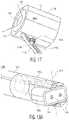
- a medical imaging systemcomprising: a rigid shaft having proximal and distal ends and an opening situated between the proximal and distal ends, the shaft defining a longitudinal axis extending between the proximal and distal ends; a rod having proximal and distal ends and situated within the opening; first and second handles coupled to the shaft at the proximal end of the shaft, wherein one of the first and second handles may be coupled to the rod; an imaging portion situated at the distal end of the shaft and coupled to the rod such that displacement of one of the first and second handles towards the other of the first and second handles rotates the camera about a second axis.
- the medical imaging systemmay further include a two- or three-dimensional camera coupled to the imaging portion.
- the imaging portionmay include an illumination source for providing illumination in a direction of the camera.
- the imaging systemmay include a rack coupled to the distal end of the rod, wherein the imaging portion may further include a pinion situated at the second axis and coupled to the rack.
- a medical imaging systemincluding: a rigid shaft having proximal and distal ends and an opening situated between the proximal and distal ends, the shaft defining a longitudinal axis extending between the proximal and distal ends; a rod having proximal and distal ends and situated within the opening; first and second handles coupled to the shaft at the proximal end of the shaft, one of the first or second handles coupled to a proximal end of the rod; and/or an imaging portion situated at the distal end of the shaft and coupled to a distal end of the rod such that displacement of one of the first and second handles towards the other of the first and second handles rotates the camera about a second axis.
- a two- or three-dimensional cameramay be coupled to the imaging portion.
- imaging portionmay further include an illumination source for providing illumination in a direction of the camera.
- a rackmay be coupled to the distal end of the rod, and the rack may include a plurality of teeth.
- a pinionmay be coupled to the rack and have an axis which is parallel to the second axis.
- the cameramay have a viewing direction which can rotate more than 120 degrees about the second axis. Accordingly, the camera may have a viewing direction which projects substantially forward or rearward along the longitudinal axis of the rigid shaft.
- an endoscope systemfor obtaining three dimension (3D) images
- the endoscope systemmay include: a multi-bandpass filter which sequentially passes a different color spectrum of light of a plurality of color spectrums of light during an image illumination interval such that a different color of light is passed during each image illumination interval of a plurality of image illumination intervals which form an image illumination period; an image capture portion which sequentially captures a plurality of images each corresponding with a different color spectrum of light which passes through the multi-bandpass filter during a corresponding image illumination interval of the plurality of image illumination intervals; an image processing portion which processes the sequentially captured plurality of images for each image illumination interval of and forms corresponding 3D image information corresponding with a plurality of the sequentially captured plurality of images; and/or a three dimensional display which may render the 3D image information.
- the endoscopemay include an illumination device including at least one source configured to sequentially output the different color spectrum of light during each image illumination interval such that different color spectrums of light are output during any two successive image illumination intervals of the plurality of image illumination intervals.
- the illumination deviceincludes: a motor; and/or a disk having one or more openings covered with at least one multi-bandpass filter and coupled to the motor, wherein the motor rotates the disk at a rotational frequency which is inversely related to image illumination period for sequentially providing different color spectrum of light during each image illumination period or interval.
- the medical endoscope systemmay include: a multi-bandpass optical filter which sequentially passes a different color spectrum of light, of a plurality of color spectrums of light, during a image illumination interval; an image capture portion which sequentially captures a plurality of images each corresponding with a different color spectrum of light which passes through the multi-bandpass optical filter; an image processing portion which processes the sequentially captured plurality of images for each image illumination interval and forms corresponding 3D image information; and/or a three dimensional display which renders the 3D image information.
- an illumination sourcemay be included and may be configured to sequentially output different color spectrums of light.
- the multi-bandpass optical filtermay further include a disk having one or more openings forming pupils.
- the multi-bandpass filtermay be located at a distal end of the endoscope.
- a method to obtain three dimensional images from an endoscopecomprising the acts of: sequentially passing a different color spectrum of light of a plurality of color spectrums of light through a multi-bandpass filter during an image illumination interval such that a different color of light is passed through the multi-bandpass filter during each image illumination interval of a plurality of image illumination intervals which form an image illumination period; sequentially capturing a plurality of images each corresponding with a different color spectrum of light which passes through the multi-bandpass filter during a corresponding image illumination interval of the plurality of image illumination intervals using an image capture portion; processing the sequentially captured plurality of images for each image illumination interval and forming corresponding 3D image information corresponding with the sequentially captured plurality of images using an image processing portion; and/or rendering the 3D image information on a display of the system configured to display three dimensional images.
- the methodmay include acts of sequentially outputting the different color spectrum of light during each image illumination interval such that different color spectrums of light are output during any two successive image illumination intervals of the plurality of image illumination intervals. Further, the method may include an act of selectively controlling a tunable multi-bandpass optical filter to pass only currently selected spectrum of light of the plurality of color spectrums of light each different from each other. The method may also include an act of synchronizing two or more of an illuminator, a multi-bandpass optical filter, and an image capture portion to operate substantially synchronously with each other to sequentially illuminate the region of interest using different color lights and to sequentially form different color images of the region of interest on a single imaging device or a single Focal Plane Array (FPA).
- FPAFocal Plane Array
- a method to obtain three dimensional images from an endoscopemay include acts of: sequentially passing a different color spectrum of light, of a plurality of color spectrums of light, during a image illumination interval using a multi-bandpass optical filter; sequentially capturing a plurality of images each corresponding with a different color spectrum of light which passes through the multi-bandpass optical filter using an image capture portion; processing the sequentially captured plurality of images for each image illumination interval and forming corresponding 3D image information using an image processing portion; and/or rendering the 3D image information on a display of the system configured to display three dimensional images.
- the methodmay further include an act of situating an optical lens portion of the endoscope between the multi-bandpass optical filter and the image processing portion at a distal end of the endoscope at an end of the endoscope and within a body barrel of the endoscope.
- the methodmay include an act of forming the main body barrel of the endoscope to have proximal and distal ends and an outside diameter less than 4 mm at the distal end.
- the methodmay further include an act of situating the multi-bandpass filter at a distal end of the endoscope.
- FIG. 1 Ais a side cross sectional view of a dual-objective endoscope in accordance with an embodiment of the present system
- FIG. 1 Bis a view of the endoscope taken along lines 1 B- 1 B′ of FIG. 1 A showing a front view of the FPA;
- FIG. 1 Cshows a front view of an FPA in accordance with an embodiment of the present system
- FIG. 1 Dis a front view of the endoscope in accordance with an embodiment of the present system
- FIG. 2 Ais a schematic view of a system using an LED light source in accordance with an embodiment of the present system
- FIG. 2 Bis a schematic view of a system using a white light source in accordance with an embodiment of the present system
- FIG. 2 Cis a schematic view of a system using a white light source in accordance with an embodiment of the present system
- FIG. 3 Ais a perspective view of an imaging unit accordance with an embodiment of the present system
- FIG. 3 Bis a perspective view of a compact imaging unit in accordance with an embodiment of the present system
- FIG. 3 Cis a schematic view of an endoscope including an imaging device having a folded imager in accordance with an embodiment of the present system
- FIG. 3 Dis a schematic view of an endoscope including an alternative imaging device in accordance with an embodiment of the present system
- FIG. 4 Awhich is a schematic view of an endoscope in accordance with an embodiment of the present system
- FIG. 4 Bis a front view of the endoscope in accordance with an embodiment of the present system
- FIG. 5is a schematic view of an endoscope system in accordance with an embodiment of the present system.
- FIG. 6is a front view of the endoscope in accordance with an embodiment of the present system.
- FIG. 7 Ais a schematic view of the imaging device components of the endoscope in accordance with an embodiment of the present system
- FIG. 7 Bis a front view of the endoscope showing semicircular right and left conjugated multi-bandpass filters (CMBFs) in accordance with an embodiment of the present system;
- CMBFsconjugated multi-bandpass filters
- FIG. 8is a schematic view of an illumination source of the endoscope in accordance with an embodiment of the present system.
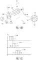
- FIG. 9which is a graph illustrating pass and stop bands of a multi-band pass filter in accordance with an embodiment of the present system.
- FIG. 10 Ais a schematic view of a system in accordance with an embodiment of the present system.
- FIG. 10 Bis a schematic view of a system in accordance with an embodiment of the present system.
- FIG. 10 Cwhich is a graph of colors passed through the first through third apertures in accordance with an embodiment of the present system
- FIG. 11 Ashows an imaging system having an endoscope with a single lens in accordance with an embodiment of the present system
- FIG. 11 Bshows an imaging system having an endoscope with a dual lens configuration in accordance with an embodiment of the present system
- FIG. 12 Ashows a front perspective view of a stereoscopic imaging system in accordance with an embodiment of the present system
- FIG. 12 Bshows a rear perspective view of a stereoscopic imaging system of FIG. 12 A in accordance with an embodiment of the present system
- FIG. 13illustrates a stereoscopic imaging device in accordance with an embodiment of the present system
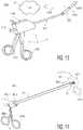
- FIG. 14illustrates an endoscope in accordance with an embodiment of the present system
- FIG. 15is a detailed view of the distal end portion of the endoscope in accordance with an embodiment of the present system.
- FIG. 16is a detailed view of the distal end portion of the endoscope in accordance with an embodiment of the present system
- FIG. 17is a detailed view of the camera portion of the endoscope in accordance with an embodiment of the present system.
- FIGS. 18 A- 18 Bare detailed views of a distal end portion of an endoscope in accordance with an embodiment of the present system
- FIG. 19shows a flow diagram that illustrates a process in accordance with an embodiment of the present system.
- FIG. 20shows a portion of a system (e.g., peer, server, etc.) in accordance with an embodiment of the present system.
- a systeme.g., peer, server, etc.
- endoscopewill refer to medical scopes for viewing an enclosed area such as, for example, laparoscopes, boroscopes, bronchoscopes, colonoscopes, choledoshoscopes, duodenoscopes, echoendoscopes, enteroscopes, esophagoschoes, gastrocopes, laryngoscopes, rhinolaryngoscopes, simoidoscopes, and/or other similar imaging apparatus.
- spectroscopic camerae.g., imaging
- vehiclessuch as aircraft, space exploration, remote controlled (e.g., unmanned) rovers, robots, etc., in (e.g., space-, air-, land-, and/or underwater-based environments.
- navigation systemsmay interface with the present system so as to provide remote navigation capabilities of these vehicles.
- the present system including spectroscopic 3D cameramay be incorporated and/or coupled with the various aforementioned and other systems and miniature configurations to provide spectroscopic 3D images, including depth perception of the images captures by the spectroscopic 3D camera, e.g., for remote navigation, imaging, exploration and the like of objects including miniature objects and/or small crevices, openings, channels in the objects, which may be any type of body, whether human, animate, and/or inanimate.
- an operative couplingmay include one or more of a wired connection and/or a wireless connection between two or more devices that enables a one and/or two-way communication path between the devices and/or portions thereof.
- an operative couplingmay include a wired and/or a wireless coupling to enable communication between a content server (e.g., a search engine, etc.) and one or more user devices.
- a further operative coupling, in accordance with an embodiment of the present systemmay include one or more couplings between two or more user devices, directly or via a network source, such as the content server.
- rendering and formatives thereof as utilized hereinrefer to providing content, such as digital media which may include, for example, audio information, visual information, audiovisual information, etc., such that it may be perceived by at least one user sense, such as a sense of sight and/or a sense of hearing.
- the present systemmay render a user interface (UI) on a display device so that it may be seen and interacted with by a user.
- the present systemmay render audio visual content on both of a device that renders audible output (e.g., a speaker, such as a loudspeaker) and a device that renders visual output (e.g., a display).
- a device that renders audible outpute.g., a speaker, such as a loudspeaker
- a device that renders visual outpute.g., a display
- the user interaction with and manipulation of the computer environmentmay be achieved using any of a variety of types of human-processor interface devices that are operationally coupled to a processor (e.g., a controller, a logic device, etc.) or processors controlling the display environment.
- a processore.g., a controller, a logic device, etc.
- the systemmay operate alone or in accordance with a user interface (UI) such as a graphical user interface (GUI) which may be rendered on a display of the system.
- UIuser interface
- GUIgraphical user interface
- the displaymay include a two- or three-dimensional display.
- Stereoscopic endoscopesinclude Conjugated Multi-Bandpass Filters (CMBFs) integrated with and/or covering one or more objective lenses (at the distal end of single and/or multiple bores) to project and form sub-images directly on a single Focal Plane Array (FPA) without using lenticular lens arrays and/or relay lenses typically used to form images on an imager and/or to relay optical images to an eyepiece at the proximal end of conventional endoscopes.
- CMBFsConjugated Multi-Bandpass Filters
- FPAFocal Plane Array
- Optical sub-imagescaptured by the FPA at the distal end of the endoscopes according to the present systems, are processed to form 3D images and/or sub-image data/information, such as by converting optical images and/or sub-images to digital form, e.g., by an analog-to-digital (A/D) converter for processing by a processor, e.g., to form 3D image data from (e.g., 3 or 6) sets of sub-image data.
- A/Danalog-to-digital
- endoscopes in accordance with embodiments of the present systemdispense with the need for a lenticular lens portion, and project right and left images directly on a single FPA without any lenticular lens portion. Accordingly, endoscopes in accordance with the present system provide images from the objective lens system to the FPA without the need for a lenticular lens or lens array. Further, both the objective lens system and the FPA may be located at a distal end of the endoscope and may be inserted inside a body for viewing a region of interest. Integrated circuitry formed on/in a semiconductor substrate such as an Integrated Silicon on Chip (ISOC) substrate may also be included at, for example, the distal end of the endoscope.
- ISOCIntegrated Silicon on Chip
- FIG. 1 Ais a side cross sectional view of a dual-objective endoscope 100 in accordance with an embodiment of the present system.
- the endoscope 100may include first and second sub-units 102 and 104 , respectively, which may be identical to each other and may be situated adjacent to each other.
- the first sub-unit 102may carry a right image and the second sub-unit 104 may carry a left image.
- the dual objective endoscope 100comprises a first bore 110 having a first lens 112 for receiving first image rays 114 from an ROI 115 ; and a second bore 120 having a second lens 122 for receiving second image rays 124 from the ROI 115 .
- the first and second lenses 112 , 122may each include several lenses, such as an objective lens ( 112 , 122 ) for collecting the image rays 114 , 124 , a focusing lens ( 116 , 126 ) to focus the collected image rays 114 , 124 on a single Focal Plane Array (FPA) 130 .
- Light sources or illuminators 150FIG. 1 D ) may sequentially illuminate the region of interest 115 with different colored lights, such as red, green and blue lights.
- the first sub-unit 102may be located in the first bore 110 and the second sub-unit 104 may be located in the second bore 120 .
- the first and second bores 110 , 120may be located in a main bore 160 of a body 165 having a distal end 170 and a proximal end 180 . Accordingly, portions of endoscopes which carry/project the right image may be known as a right image channel and those portions of the endoscope which carry/project the left image may be known as a left image channel.
- the distal end 170 of the endoscope 100is typically inserted within a body 182 through a cavity or opening 184 of a body 170 while the proximal end 180 remains outside of the body 105 .
- the body 170may be that of a patient, human or otherwise, as well as the body of any inanimate object where it is desired to look inside the object.
- the lenses 112 , 122may simultaneously receive light reflected from the region of interest 115 for simultaneously imaging the first/right and second/left image rays 114 , 124 on different (right and left) areas 132 , 134 , respectively, of the FPA 130 .
- the time-sequential illuminationprovides RGB light one at a time
- a full color imageis collected on the FPA 130 .
- three (e.g., RGB) right imagesmay be sequentially superimposed on the right area 132
- simultaneously three (RGB) left imagesmay be sequentially superimposed on the left area 134 , as described in connection with FIGS. 1 B- 1 D .
- three imagesmay be captured to form a full color image.
- six imagesmay be necessary to obtain a full color image.
- FIG. 1 Bis a view of the endoscope 100 taken along line 1 B- 1 B′ of FIG. 1 A showing a front view of the FPA 130 .
- the right image area 132 of the FPA 130captures the first/right image rays (projection) 114 and the left image area 134 of the FPA 130 captures the second/left image rays (projection) 124 .
- a round FPA 130 and square image areas 132 , 134are shown, it is envisioned that the FPA 130 and image areas 132 , 134 may include other shapes and/or sizes, such as an oval and/or a rectangular shape type, etc., where the FPA 130 and the image areas 132 , 134 may have the same or different shape types. For example, FIG.
- FIG. 1 Cshows a front view of an oval FPA 130 ′ in accordance with another embodiment of the present system.
- the FPA 130 ′includes square (or round or any desired shape) right image area 132 ′ and left image area 134 ′ which correspond with the right image area 132 and the left image area 134 , respectively, of the FPA 130 shown in FIG. 1 B .
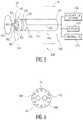
- FIG. 1 Dis a front view of the endoscope 100 along line 1 D- 1 D′ of FIG. 1 A showing an imaging unit 190 that includes the right objective lens 112 , and the left objective lens 122 , where both lenses 112 , 114 simultaneously receive light emitted from illuminators 150 and reflected from the ROI 405 .
- the illuminators 150may be arranged around the periphery of the imaging unit 190 and may be configured (e.g., under the control of a controller or processor) to sequentially provide different light of different wavelengths and therefore colors (e.g., corresponding with an RGB spectrum) one at a time.
- the illuminators 150may provide red light, in response to which red right and left images may be captured simultaneously on the right image area 132 and the left image area 134 of the FPA 130 (shown in FIG. 1 A- 1 B ). Then, at a later time such as at time t 2 , the illuminators 150 may provide green light, and green right and left images may be captured simultaneously on the right image area 132 and the left image area 134 of the FPA 130 . Then, at yet a later time such as t 3 , the illuminators 150 may provide blue light and blue right and left images may be captured simultaneously on the right image area 132 and the left image area 134 of the FPA 130 .
- the systemmay then superimpose information related to the captured green and blue right and left images (e.g., captured at times t 2 and t 3 ) upon the captured red right and left images (e.g., captured at time t 1 ) so as to form a full color three dimensional images which may be displayed on a display of the system. Accordingly, after time t 3 , that is after three sequences of illumination (e.g., of red, green, and blue light), a full color image may be captured by the right and left image areas 132 and 134 , respectively, for further processing by an Integrated Silicon on Chip (ISOC).
- ISOCIntegrated Silicon on Chip
- three images from each of the right and left image areas 132 and 134 , respectively, of the FPA 130may be processed to form a full color image, where a right image is formed on a right image area 132 of the FPA 130 , and a left image is formed on a left image area 134 of the FPA 130 .
- a processormay be configured to correlate and combine the three right and left images to form a stereo and/or 3D image.
- FIG. 2 Ais a schematic view of a system 200 A using an LED light source in accordance with an embodiment of the present system.
- the system 200 Amay include an endoscope (e.g., such as an endoscope viewed from the front having an imaging unit 190 ′), red, green, and blue LEDs 210 , 212 , and 214 , respectively, which may provide corresponding light (e.g., red, green, and blue) to an illuminator 150 of the imaging unit 190 ′ via a light channel 230 .
- the light channel 230may include any suitable light conducting channel such as a fiber optic light channel, an acrylic light channel, etc.
- the light channel 230comprises one or more fiber optics to directly illuminate the ROI 15 from light exiting through the distal or exit end(s) of the fiber optics(s), such as through the illuminators 150 shown in the various figures of the various embodiments, such as FIGS. 1 D, 2 A- 2 C, 5 - 8 , and 10 A- 10 B , for example.
- one or more interface unitssuch as one or more periscopes to be described in connection with FIG. 16 , may receive light from the distal end(s) of the light guide(s), e.g., at least one fiber optic cable.
- the periscope(s)directs, e.g., reflects, light into a light exit unit which is located around the right and left pupils and directs light out to illuminate the ROI 115 .
- the light channel 230may also include a coupler portion which may couple the LED 210 , 212 , and/or 214 to the light channel 230 and a decoupler portion which may couple the light channel 230 to the illuminator 150 .
- the LEDs 210 , 212 , and/or 214may emit monochromatic light and may be sequentially turned on one at a time under the control of a controller 220 .
- the controller 220 and/or the LEDs 210 , 212 , and/or 214may be located at, or connected to, a proximal end 180 ( FIG.
- the endoscope 100for example, such that the light provided by the LEDs may be transmitted through light guide(s) or light channel(s) 230 such as fiber optic(s), to the illuminators 150 of the imaging unit 190 ′ at the distal end of the endoscope 100 .
- FIG. 2 Bis a schematic view of a system 200 B using a white light source 235 in accordance with another embodiment of the present system.
- the white light source 235may include a suitable light source emitting light which corresponds with a desired spectrum or spectrums such as a white spectrum.
- a filtersuch as a filter 237 may be included to pass only desired wavelengths (or frequencies, etc.) of light under the controller 220 .
- the filter 237may include a solid state and/or analog filter.
- the filter 237may include a rotating color wheel 240 that has three openings covered with red, green and blue filters 250 , 252 , 254 , respectively.
- the filtermay sequentially pass a single color of light to the illuminators 150 via the light channel 230 at a time.
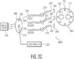
- FIG. 2 Cis a schematic view of a system 200 C using a white light source 235 in accordance with an embodiment of the present system.
- the system 200 Cmay be similar to the system 200 B.
- the system 200 Cmay include a rotating wheel 280 which may include a single opening (as opposed to the three openings of the rotating wheel 240 of system 200 B) and filtered light channels ( 270 , 272 , and 274 ).
- the filtered light channels 270 , 272 , 274may pass only desired wavelengths of light such as wavelengths of light which correspond with red, green, and blue light spectrums, respectively (and therefore block other wavelengths of light).
- the rotating wheel 280may include a plurality of openings.
- the lightmay pass from the white light source 235 through the opening to a single one of the filtered light channels 270 , 272 , 274 .
- color filtersare associated with the light channels, such as provided at entrance and/or exit faces 260 , 262 of each of the light channels 270 , 272 , 274 .
- three light channels 270 , 272 , 274are provided, one having a red filter, a second channel having a green filter and the third light channel having a blue filter.
- the rotating wheel 280has one opening 285 that allows white light from a white light source 235 to pass to one channel when the opening is aligned with the channel or light guide.
- the opening 285sequentially allows white light to enter the entrance faces on one channel at a time.
- the opening 285is aligned with the red channel 270 so that red light 290 is provided to the illuminators 150 at the distal end of the endoscope.
- green light 292is provided to the illuminators 150 and so on, where similarly at a later time t 3 when the wheel 280 rotates and the opening is aligned with the blue channel 274 , then blue light 294 is provided to the illuminators 150 for illuminating the ROI sequentially with red, green and blue lights 290 , 292 , 294 .
- the FPA 130 of an endoscope in accordance with an embodiment of the present systemmay simultaneously capture right and left optical images directly received (e.g., one color at a time) from an objective lens system of the endoscope and convert right and left optical images (via an analog-to-digital converter (A/D)) to digital signals which may then be processed by an Integrated Silicon on Chip (ISOC). That is, at time t 1 , both right and left red images (e.g., of an ROI) are simultaneously imaged on the right and left areas 132 , 134 of the FPA 130 ( FIGS.
- A/Danalog-to-digital converter
- both right and left green imagesare simultaneously imaged on the right and left areas 132 , 134 of the FPA 130 ; and at time t 3 , both right and left blue images are simultaneously imaged on the right and left areas 132 , 134 of the FPA 130 .
- the various illumination schemes and system shown in FIG. 2 A- 2 Cmay be used with various embodiments of the present endoscopes and/or systems, and different combinations thereof, such as single and/or double bore endoscopes, using mono and/or color FPA, to form sub-images on the entire or sub-portions of the FPA, for example.
- FIG. 3 Ais a perspective view of an imaging unit 300 in accordance with an embodiment of the present system.
- the imaging unit 300may include one or more of an FPA 310 and an Integrated Silicon on Chip (ISOC) 320 which are formed on the same surface of a semiconductor substrate adjacent to where the FPA 310 .
- ISOCIntegrated Silicon on Chip
- FIG. 3 Bis a perspective view of a compact imaging unit 325 in accordance with another embodiment of the present system.
- the imaging unit 325may include an FPA 330 on a first side of a substrate and an ISOC 340 on an opposite side of the substrate. Accordingly, the imaging device 325 may have a footprint which is substantially identical to a footprint of the single FPA 330 where the ISOC 340 is on opposite side of the substrate of the FPA 330 .
- the imaging unit 325may be referred to as a folded imager 325 .
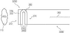
- FIG. 3 Cis a schematic view of an endoscope 300 C including an imaging device having a folded imager 325 C in accordance with an embodiment of the present system for capturing images from the ROI 115 .
- the folded imager 325 Cmay be formed from stacked layers 360 , 360 ′, 360 ′′ stacked axially along a longitudinal axis 365 of the endoscope 300 C.
- the imaging device 325 Cmay include a single FPA 330 at a front end 372 and the processing circuits (e.g., including an ISOC) 340 C formed on at least one layer stacked at a back end 374 of the imaging device 325 C (which may be similar to the imaging device 325 shown in FIG. 3 B ) over the single FPA 330 .
- the ISOC stack(s) 340 Cmay be connected to the single FPA 330 through connection bumps 370 .
- FIG. 3 Dis a schematic view of an endoscope 300 D including an alternative imaging device 325 D in accordance with an embodiment of the present system for capturing images from the ROI 115 .
- the imaging device 325 Dmay include a folded substrate 380 having the single FPA 330 at the front end 672 and the ISOC 340 D at the back end 374 of the imaging device 325 D.
- the folded flexible substrate 380may be formed from patterned silicon membrane or flexible printed circuit boards, or other suitable material.
- the optical images captured by the FPA 330are converted (by an A/D) to digital signals (e.g., digital image information) which may be processed by an image processor such as the ISOC 340 located behind the FPA 330 .
- the ISOC 340processes the digital signals (i.e., the digital image information representing the optical images captured by the FPA 330 ) and outputs video signals which are transmitted (e.g., using a wired or wireless communication method) to a display screen of the system for viewing of 3D/stereo images of the ROI 115 ( FIG. 1 A ) by a user (e.g., a surgeon, etc.).
- the systemmay also record 3D image information corresponding with the images for later use and/or may transmit the 3D image information to one or more locations for remote viewing (e.g., by a remote surgeon, etc.).
- Another embodiment of the present inventionuses a split pupil having right and left pupils.
- different right and left imagesmay be captured by the FPA and processed to form a 3D image.
- both the right and left portions of the FPA (or right and left pupils)e.g., corresponding with right and left image channels, respectively
- each image channelhas its own bore (e.g., 110 , 120 ) as shown in FIG. 1 A
- different right and left images received by the right and left pupils or lenses 112 and 122 , respectivelyare imaged on different areas 132 , 134 of the FPA 130 , as shown in FIG. 1 B , thus providing stereoscopic image information which may be processed to form a 3D image.
- CMBFsConjugated Multi-Bandpass Filters
- the right and left pupilsmay be formed by a single lens having right and left pupil portions, or two dedicated lenses, one lens for the right pupil and one lens for the left pupil, for use in single and/or dual bore endoscopes.
- switchable liquid crystal (LC) shutters or mechanical shuttersmay be controlled by a controller such that only one pupil passes image light reflected from the ROI at any one time to project the passed image light over substantially the entire area of the FPA, thus increasing resolution as compared to projecting images on only a portion of the FPA, where a processor construct a 3D image from six sequential sub-images (R R , R L , G R , G L , B R , and B L ), each projected over the entire FPA area.
- right and left imagesmay be simultaneously projected over right and left portions of the FPA, resulting in reduced resolution, however, faster acquisition time for forming a 3D image, since the 3D image in this case is constructed by the processor from three (instead of six) sequential projections of simultaneous right and left sub-images (R R R L , G R G L , and B R B L ).
- the controller and/or processormay vary a voltage applied to right and left LC shutters located over the right and left pupils, such that one LC shutter is open/transparent to pass the image light, and the other LC shutter is closed or not transparent to block the image light from passing through the other shutter.
- a controllermay control movement of a mechanical shutter, as shown in FIGS. 4 A- 4 B .
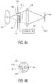
- FIG. 4 Ashows a schematic view of an endoscope system 400 in accordance with another embodiment of the present system.
- the endoscope system 400includes one or more of a controller 410 , a micro-electro-mechanical (MEMS) shutter 415 for allowing time multiplexing of sub-images, an illumination portion 420 , 420 ′, a lens portion 425 , and an FPA 430 .
- the illumination portion 750may include a light source, e.g., an external white light source in case the FPA is a color FPA having a color filter, or a light source(s) that provides different colors of light sequentially, e.g., Red (R), Green (G), and Blue (B) light.
- a light sourcee.g., an external white light source in case the FPA is a color FPA having a color filter, or a light source(s) that provides different colors of light sequentially, e.g., Red (R), Green (G), and Blue (B
- Optical guidesmay also be provided to direct the external light form the proximal end to a distal end of the endoscope where the light is then directed away from the endoscope to illuminate an ROI 115 .
- colored light source(s)may also be used with a monochrome FPA, where each color sequentially illuminates the ROI 115 .
- the lens portion 425may include one or more lenses which may project a right or left image of the ROI 115 upon the FPA 430 depending upon settings of the shutter 415 as will be discussed below.
- the shutter 415may include a right shutter opening (or pupil) 440 and a left shutter opening (or pupil) 445 which may block or allow light to pass therethrough based upon a control signal from the controller 410 .
- the right and left shutter openings (pupils) 440 , 445may include filters, shutters, or gates which may operate under the control of the controller 410 and act to pass or block light from passing therethrough based upon one or more control signals transmitted from the controller 410 to the shutter 415 so as to allow only right or left images to be projected upon the FPA 430 at any one time.
- the right shutter opening 440may be opened so as to allow light to pass therethrough and the left shutter opening 445 may be substantially or fully closed so as to block light from passing therethrough.
- the FPA 430may be controlled to capture a right image (e.g., at a given wavelength).
- the left shutter opening 445may be opened so as to allow light to pass therethrough and the right shutter opening 440 may be substantially or fully closed so as to block light from passing therethrough.
- the FPA 430may be controlled to capture a left image or a portion thereof (e.g., a red, green, or blue portion/sub-image).
- the right pupilmay be blocked and light may be allowed to pass only through the left pupil, and vice verse.
- the shuttermay include a liquid crystal (LC) type shutter which may be electronically controlled (e.g., by the controller 410 ) to allow light to pass or block light from passing through a corresponding right or left pupil 440 and 445 , respectively.
- the controller 410may apply a voltage to right or left shutter covering the right and left pupils 440 and 445 , respectively, to control a state (e.g., open or blocked) of a corresponding shutter.
- LCliquid crystal
- the shutter 415may include a mechanical shutter portion (e.g., a rotating disk or a linear shutter coupled to a motor controlled by the control portion 410 ) which may be mechanically rotated or linearly moved back and form between the two pupils 440 , 445 , to block one of the pupils.
- a mechanical shutter portione.g., a rotating disk or a linear shutter coupled to a motor controlled by the control portion 410
- the shutter 415may include a mechanical shutter portion (e.g., a rotating disk or a linear shutter coupled to a motor controlled by the control portion 410 ) which may be mechanically rotated or linearly moved back and form between the two pupils 440 , 445 , to block one of the pupils.
- FIG. 4 Bis a front view of the endoscope system 400 in accordance with an embodiment of the present system.
- the shutter 415may be mounted at the distal end of the endoscope 400 .
- the shutter 415is shown in a position covering or closing the left pupil 445 such that light cannot pass through the left pupil 445 .
- the right pupil 440is shown in an open position in such that light can pass through the right pupil 440 . Accordingly images of, for example, the ROI 115 may only pass through the right pupil 440 and will not pass through the left pupil 445 at the present cycle.
- white lightmay be used along with a color FPA or an FPA having a color filter.
- the illumination portion 420 , 420 ′may provide white light and the FPA 430 may include a color FPA which may form color images.
- a color FPAmay include, for example, a monochrome FPA with a color filter array of RGB filters situated at, for example, the right and left shutter openings 440 and 445 , respectively.
- the color filtersmay include an RGB filter group and may be provided on, for example, a wheel (e.g., a rotating wheel as discussed elsewhere) or may be controlled by the controller 410 , or a further controller/processor, so as to block certain colors and/or to allow other colors to pass therethrough.
- color imagesmay be formed using a monochrome FPA with color filters (e.g., RGB) at the pupils/lenses 440 , 445 , such as Conjugated Multi-Bandpass Filters (CMBFs) and/or tunable filters that may be tuned by the controller or processor 410 to each one of desired bands selectively, synchronized by the processor with the illumination, such as with 3 or 6 illumination sequences to capture 3 sub-images (where right and left images are simultaneously imaged on right and left sides of the FPA, for each of the red (R), green (G) and blue (B) colors, or any desired colors) or 6 sub-images (where each of the 6 RGB right and left sub-images are imaged on the substantially entire area of the FPA).
- CMBFsConjugated Multi-Bandpass Filters
- tunable filtersthat may be tuned by the controller or processor 410 to each one of desired bands selectively, synchronized by the processor with the illumination, such as with 3 or 6 illumination sequences to capture 3 sub-
- the ROI 115may be illuminated with colored light (e.g., instead of white light) to sequentially provide RGB images to the FPA through the CMBFs or tunable filters formed over or integrated with the right and left pupils/lenses 440 , 445 .
- colored lighte.g., instead of white light
- Shuttersmay be used with RGB light under the control of the controller 410 so as to pass certain colors and block other colors at certain times.
- the controller 410may include functionality to synchronize the shutters (either mechanical shutters or LC shutters) with the illumination such that, for example, red light is provided (e.g., by the illumination source) when a color (e.g. R, G, or B) filter is activated or a tunable filter is tuned to pass a desired color light and/or sub-red light.
- a colore.g. R, G, or B
- CMBFscomplementary or Conjugated Multi-Bandpass Filters
- the illuminationis provided through a multi-band pass filter which is matched to the complementary right (R R G R B R ) and left (R L G L B L ) multi-band pass filters located at the right and left pupils/lenses.
- the right (R R G R B R ) and left (R L G L B L ) conjugated or complementary multi-band pass filters at the right and left pupilsdo not require energy, have no moving parts, and do not require synchronization, since these right (R R G R B R ) and left (R L G L B L ) multi-band pass filters are matched to the illuminating light.
- this R R lightwill reflect back from the object of interest and enter or pass through only the right pupil through the band pass filter R R at the right pupil, and is blocked from entering or passing through the left pupil by the left (R L G L B L ) multi-band pass filter located over the left pupil.
- FIG. 5is a schematic view of an endoscope system 500 in accordance with an embodiment of the present system.
- the endoscope system 500may include an endoscope 502 including single bore or housing 505 (instead of having two bores 110 , 120 of the dual objective endoscope 100 shown in FIG. 1 A ).
- the endoscope system 500may provide a stereoscopic 3-D image of an object or the ROI 115 inside of the body 182 .
- the endoscope 502may be inserted into the body 182 through an opening or cavity 184 which, for example, may include a natural opening, an incision, etc.
- the housing 505may have a distal end 510 and a proximal end 515 , where the distal end 510 is insertable into the cavity or opening 184 of the body 182 .
- An imaging device 325 for obtaining optical images of the ROI 115is located at the distal end 510 and may include an imager or FPA 330 which may capture images projected thereon, a processor to process the images captured by the FPA 330 and to form output signals such as video signals.
- the processormay include ISOC circuitry 340 or other suitable processor(s), where the ISOC including the processor(s) 340 is behind the FPA 330 and has the same footprint of the FPA 330 , where a length or diameter of the footprint may be 4 mm or less, such as 1-4 mm including any sizes therebetween, such as 3-4 mm, 2-4 mm, 2-3 mm, etc.
- the imaging device 325 devicemay be coupled to one or more of an illumination source 550 , a display 555 , and a controller 595 using wired and/or wireless coupling techniques and/or connecting devices.
- a cable 545may couple the imaging device 325 to the illumination source 550 , the display 555 , and/or the controller 595 .
- the cable 545may include a signal line to transmit video signals (e.g., from the ISOC) to the display 555 for displaying the optical images of the ROI 115 in multi-dimensions (e.g., 3D, etc.). It is further envisioned that a wireless coupling may be used to transmit the video signals from the ISOC 340 to the display 555 .
- the cable 545may include one or more light guide to channel light from the illumination source 550 to the illuminators 150 at the front end of the imaging device 325 .
- the illuminatorsmay be incorporated within the imaging device 325 so as to illuminate the ROI 115 under the control of the controller 595 .
- the imaging device 325may include a single focal plane detector array such as the FPA 330 at a front end 565 (of the imaging device 625 ) facing the region of interest (ROI) 115 for capturing images of the ROI 115 .
- the imaging device 325may further include processing circuits having suitable processors such as, for example, the ISOC 340 which may be located at a back end 575 (of the imaging device 325 ) behind the FPA 330 and may have the same footprint as the FPA 330 so that the ISOC 340 does not enlarge an outer cross section 580 of the imaging device 325 , where the cross section 580 may be less than 4 mm, such as between 1-4 mm.
- the ISOC 340may be operative to convert the optical images captured by the FPA 330 into the video signals for display on the display 555 .
- the imaging device 325may include right and left pupils 585 and 590 , respectively, which have complementary right (R R G R B R ) and left (R L G L B L ) multi-band pass filters, respectfully, where a single lens 730 ( FIG. 7 A ) in the single bore or housing 505 (unlike the dual lenses 112 , 122 in the two bores 110 , 120 of FIG. 1 A ) projects right and left images on the FPA 330 .
- the right and left pupils 585 and 590are different from the right and left lenses 112 and 122 , respectively, of the dual objective endoscope of FIG. 1 A which independently and simultaneously images right and left images on an FPA.
- An area of a cross section 580 of the endoscope 502is compact so as to easily pass through an opening or incision in a body.
- the right pupil 585receives a right image through a right multi-band pass filter (such as Conjugated Multi-Bandpass Filters (CMBFs) 710 , 720 shown in FIG. 9 ) having right three pass bands R R G R B R 710 as illustrated in FIGS. 7 and 9 .
- CMBFsConjugated Multi-Bandpass Filters
- the left pupil 590receives a left image through a left multi-band pass filter (such as filter 720 shown in FIGS. 7 and 9 ) having left three pass bands R L G L B L as illustrated in FIG.
- FIG. 9which is a graph illustrating pass bands and stop bands 910 , 920 of a Conjugated Multi-Bandpass Filters (CMBFs) 710 , 720 in accordance with an embodiment of the present system.
- the right multi-band pass filter 710 having the right three pass bands R R G R B Ris the complement of the left multi-band pass filter 720 having left three pass bands R L G L B L . That is, the pass bands R R G R B R of the right multi-band pass filter 710 corresponds to the stop bands 920 of the left multi-band pass filter 720 .
- the pass bands R L G L B L of the left multi-band pass filter 720corresponds to the stop bands 910 of the right multi-band pass filter 710 .
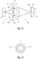
- FIG. 7 Ais a schematic view of the imaging device 325 components of the endoscopic system 500 ( FIG. 5 ) in accordance with an embodiment of the present system.
- the imaging device 325may further include a lens system 730 .
- the lens system 730may include several lenses, such as an objective lens and a focusing lens for imaging the right image 740 and the left image 750 directly on the (single) FPA 330 .
- the illuminators 150(see also FIGS. 4 D and 6 ) illuminate the ROI 115 through Conjugated Multi-Bandpass Filters (CMBFs) 810 (shown in FIG. 8 ), having the right three pass bands (R R G R B R ) and the left three pass bands (R L G L B L ).
- CMBFsConjugated Multi-Bandpass Filters
- the multi-band pass filter 810may be matched to the right multi-band pass filter 710 and the left multi-band pass filter 720 ( FIGS. 7 A- 7 B and 9 ) covering the right and left pupils, respectively, so that when the ROI 115 is illuminated with one color light, such as in the right red band R R , then this R R light reflected from the ROI 115 passes through the right pupil 585 through the pass band R R of the right multi band filter 710 R R G R B R covering the right pupil 585 , and is blocked from passing through the left pupil 590 by the stop band 920 ( FIG. 9 ) of the left multi band filter 720 R L G L B L covering the left pupil 590 .
- both right and left imagese.g., R R and R L images
- the illumination source 550may be situated remotely from the endoscope 502
- the illumination source 550may be situated within the housing 505 of the endoscope 502 and may be adjacent to or formed integrally with the illuminators 150 .
- the right and left conjugated multi-bandpass filters (CMBFs) 710 ′, 720 ′, used to pass right and left sub-images R R G R B R R L G L B,may each have a semicircular shape which are placed next to each other to form a full circular conjugated multi-bandpass filter which may be placed over a lens and/or a transparent support substrate, such as removably placed on a front and/or a back surface of the lens and/or the transparent support substrate, or removably inserted into an objective lens, or integrated with a lens, to form and/or cover the right and left pupils of the imaging device 325 .
- CMBFsright and left conjugated multi-bandpass filters
- Thisprovides for easily converting the binocular two-pupil imaging unit or camera 325 into a monocular camera by simply removing the CMBF pair 710 ′, 720 ′ allowing a user/operator of the endoscope to select between binocular and monocular imaging to obtain better images depending on the environment and desired viewing distances.
- monocular imagingmay be selected and used to view long viewing distances, where depth perception is not as important, while binocular imaging to obtain depth perception may be used for viewing short distances.
- the binocular imaging systems using the CMBF pair 710 , 720provides better depth resolutions than that without the CMBF over the viewing distances range between 6 to 12 mm.
- Improved depth perception or depth resolutionis provided at working or viewing distances of 5 mm to 2 cm with a 60 degree field of view using a negative or wide angle lens by the embodiments using right and left lenses or openings/apertures separated by a distance between 0.5 mm to 2 mm, such as a distance of 1 mm, as well as the embodiments where the right and left images are captured by the semicircular CMBF pair 710 ′, 720 ′ shown in FIG. 7 B .
- FIG. 8is a schematic view of an illumination source 550 (also shown in FIG. 5 ) of the endoscope 500 in accordance with an embodiment of the present system.
- the illumination source 550may include a plurality of sources 830 , 832 , 834 , 840 , 842 , 844 and corresponding pass band filters (PBFs) R R , G R , B R , R L , G L , and B L of a multi bandpass filter 810 .
- PPFspass band filters
- the sources 830 , 832 , 834 , 840 , 842 , and 844may include any suitable white light sources such as Xenon sources, etc.
- the controller 595may control the illumination source 550 such that the illumination source 550 sequentially turns on the light sources 830 , 832 , 834 , 840 , 842 , 844 one at a time so as to illuminate the ROI 110 via light guide(s) 820 and the illuminators 150 of the imaging device 325 .
- lenses 825may also be provided between the CMBFs 810 and the light guide(s) 820 .
- light from the sources 830 , 832 , 834 , 840 , 842 , 844may pass through the corresponding illumination pass-band filters (PBFs) R R , G R , B R , R L , G L , and B L of the illumination multi bandpass filter 810 so that the region of interest (ROI) 115 is illuminated one at a time by light within one of the three right pass bands (R R G R B R ) and the three left pass bands (R L G L B L ) during each illumination interval.
- the illuminating lightis reflected from the ROI 115 and is passes through the right or left multi-band pass filter 710 , 720 (shown in FIGS.
- the individual imagesmay captured by the FPA 330 may be superimposed to form a full color image.
- the image data from the ISOC 340is processed using an algorithm at the display site to combine and form 3D images from the 3 or 6 sub-images and/or image data.
- the right and left imagesmay be superimposed at the viewing plane of the display 555 .
- each image information or dataare processed and correlated by a processor to form 3D images displayed on a display 555 ( FIG. 5 ).
- six imagesmay be used to form the full color formed on substantially the entire FPA area 1110 ( FIG. 11 A ). That is, each one of the six images R R , G R , B R , R L , G L , B L (in any sequence) may be formed on the entire area 1110 ( FIG. 11 A ) of the FPA 330 .
- any sequence of illumination using the six Xenon (white) light sourcesmay be used, where three (R R G R B R ) right sub-images may be collected and superimposed to form a right image, and three (R L G L B L ) left sub-images may be collected and superimposed to form a left image. That is, the illumination to provide the six sources 830 , 832 , 834 , 840 , 842 , 844 may be in any sequences such as R R , G R , B R , R L , G L , B L , or R R , R L , G R , G L , B R , B L , etc. It should be noted that since each color is divided into right and left bands, such as Red Right (R R ) and Red Left (R L ), the right and left images are not exactly the same color, but are metamers.
- a full color imagemay be collected after three illuminations (where each right and left image is simultaneously projected on respective right and left halves 1150 , 1155 of an image capture portion such as the FPA 330 ′ of FIG.
- the second illumination with light in the band G R , G Lis used to image right and left green images simultaneously on the right and left FPA areas 132 , 134 (where the green images are superimposed on the red images), and the third illumination with light in the band B R , B L is used to image right and left blue images simultaneously on the right and left FPA areas 132 , 134 (where the blue images are superimposed on the previously images red and green images).
- any sequence of illumination using three Xenon (white) light sourcesmay be used, such as R R R L , G R G L , B R B L or G R G L , R R R L , B R B L , etc.
- FIG. 10 Ais a schematic view of a system 1000 A in accordance with an embodiment of the present system.
- the system 1000 Amay be similar to the endoscope system 500 .
- the system 1000 Amay include two white light sources (e.g., Xenon, etc.), as will be discussed below, which provide illumination instead of three white (Xenon) light sources for illumination to form the right image and another three Xe light sources for illumination to form the left image as was described above in connection with the embodiment of FIG. 8 .
- the system 1000 Aincludes one right light source 1010 is for illumination to form the right image, and one left light source 1020 is for illumination to form the left image.
- a right rotating wheel 1080having a single opening 1085 for sequentially illuminating RGB right channels or light guides 1070 , 1072 , 1074 (inside the endoscope 502 ) that include RGB filters, respectively, such as at their entrance or exit ends 1050 , 1060 , similar to the embodiment described in connection with FIG. 2 C .
- a left light source 1020provides white light through the opening 1087 of a left rotating wheel 1082 for sequentially illuminating one at a time the entrance side 1050 of left channels or light guides 1075 , 1077 , 1079 that include RGB filters, respectively.
- the right and left light sources 1080 and 1020may be controlled by the controller 595 ( FIG. 5 ).
- the right and left wheels 1085 and 1082may be controlled by the controller 595 ( FIG. 5 ) to rotate at a desired angular frequency ( ⁇ ) and may be synchronized with operation of the right and left sources 1080 and 1020 , respectively, and/or the FPA.
- the right and left light guides 1070 , 1072 , 1074 , 1075 , 1077 , 1079are coupled to the illuminators 150 for illuminating the ROI 115 .
- FIG. 10 Bis a schematic view of a system 1000 B in accordance with an embodiment of the present system.
- a white source 1010such as a Xenon lamp
- first, second and third apertures 1038 R, 1038 G, and 1038 Brespectively, used to receive white light from the source 1310 , for example.
- the three apertures 1038 R, 1038 G, and 1038 Bare respectively covered with, or include, red, green, and blue filters, where each filter includes both the right and left band portions. More particularly, the first aperture 1038 R is includes a R R R L filter, the second aperture 1038 G includes a G R G L filter and the third aperture 1038 B includes a filter B R B L filter.
- the three apertures 1038 R, 1038 G, and 1038 Beach may pass light of a different color spectrum as illustrated in FIG. 10 C which is a graph of colors passed through the first through third apertures 1038 R, 1038 G, and 1038 B, respectively, in accordance with an embodiment of the present system.
- R R R L , G R G L , and B R B L filters of the first, second and third apertures 1038 R, 1038 G, 1038 B, respectively,may pass corresponding colors and block other colors of light from the source 1310 as the wheel 1383 rotates.
- rotation of the wheel 1083 with the three aperturessimultaneously provides both right and left one color (e.g., red, green, and blue, in sequence) illumination for simultaneously imaging both right and left red images on the right and left areas 1150 , 1155 of the FPA 330 ′ shown in FIG. 11 B .
- the image information obtained from the FPA 330 ′may be processed and a corresponding full color image is obtained.
- FIG. 11 Ashows an imaging system 1100 A having an endoscope with a single lens 1130 in accordance with an embodiment of the present system.
- the single lens 1130may sequentially receive one at a time six sub-images of the right and left images from the right and left multi-band pass filters 710 and 720 , respectively, covering the right and left pupils 585 and 590 , respectively.
- the single lens 1130may form the image on the entire (or a substantial portion of) an image capture area 1110 of the FPA 330 .
- the systemmay process six sequential images captured during six sequential illuminations and process the six sequential images to form a full stereo (e.g., right and left) color image.
- the six sequential imagesmay correspond with a sequential formation of RGB right and RGB left images on the entire image capture area 1110 of the FPA 330 (in any sequence such as R R , G R , B R , R L , G L , B L , or R R , R L , G R , G L , B R , B L , etc.).
- the entire or a substantial portion of the image capture area 1110 of the FPA 330may be used to from a single image.
- the FPA 330may have a cross section (e.g., an image capture area) which is shaped and sized such that an image of sufficient detail may be captured.
- the FPA 630may include a circular cross section 1120 .
- shape of the FPA cross section and/or FPA image portionsmay any shape, such as circular, oval, square, rectangular, etc.
- FIG. 11 Bshows an imaging system 1100 B having an endoscope with a dual lens configuration in accordance with an embodiment of the present system.
- the endoscope system 1100 Bis similar to the endoscope system 1100 A.
- the endoscope system 1100 Bincludes two lenses 1140 , 1145 (as opposed to a single lens).
- the two lenses 1140 , 1145may simultaneously receive right and left images from the right and left multi-band pass filters 710 and 720 , respectively, covering the right and left pupils 885 and 890 , respectively.
- Each of the two lenses 1140 and 1145projects an image of a ROI 115 on a half the FPA area.
- the right lens 1140forms an image on the right FPA area 1150 (e.g., a right halve) and the left lens 1145 forms an image on the left FPA area 1155 (e.g., left halve).
- the FPAmay have an oval cross section 1160 .
- other shapes and sizesare also envisioned.
- a single lenssuch as the lens 1130 shown in FIG.
- a full color stereo (right and left) color imageis formed using image information which corresponds with images from three sequential illuminations, each of which may correspond with:
- the three time-sequential illuminationsprovide three illuminations in the following three bands R R R L , G R G L , B R B L in any sequence (G R G L , R R R L , B R B L , or B R B L , G R G L , R R R L etc.)
- the full color imagemay be formed after six sequential illuminations for providing light in the six bands sequentially, R R , G R , B R , R L , G L , B L , or in any other sequence.
- a triangulatormay be provided to adjust an alignment of imaging portions (e.g., lenses, etc.) apparatus such that they may be parallel or non-parallel (e.g., toed inward) to each other.
- the triangulatormay be controlled by automatically by a controller/processor and/or manually by a user.
- imaging systems discussed abovemay be incorporated into endoscopes such as scissor-type rotating angle MIS endoscopes as will be discussed below with reference with FIGS. 12 A through 21 .
- FIG. 12 Ashows a front perspective view of a stereoscopic imaging system 1200 in accordance with an embodiment of the present system.
- the stereoscopic imaging system 1200may include an imaging portion which has two lenses 1214 so as to capture stereoscopic images as described above.
- Illuminators 1212may receive light (e.g., RGB, or white light) from a light source (e.g., LEDs, Xenon bulbs, etc.) via a light guide(s) such as a fiber optic cable(s) 1204 , and emit light for illuminating a ROI for viewing and/or image capture.
- a light sourcee.g., LEDs, Xenon bulbs, etc.
- the illuminators 1212may include light from, for example, one or more light sources situated within the body portion 1202 which may include a lens barrel 1210 attached thereto.
- the body portion 1202may be sized and/or shaped as desired (e.g., round, square, oval, etc.).
- An image capture portionsuch as a CCD (Charge-Coupled Device), CMOS (Complementary Metal Oxide Semiconductor device), FPA, etc., and/or an image processing portion may be included within the body portion 1202 .
- the FPAmay capture images projected thereon by one or more lenses, filters, pupils, etc., situated within the lens barrel 1210 .
- the processing portionmay process the images for transmission via, for example, one or more power and signal cables 1206 to be displayed on a display.
- the lens barrel 1210may be attached to the body portion 1202 via an interface 1208 such as a bayonet mount, etc. Accordingly, the lens barrel may be swapped and/or removable from the body portion 1202 .
- FIG. 12 Bshows a rear perspective view of a stereoscopic imaging system 1200 of FIG. 12 A in accordance with an embodiment of the present system.
- the imaging portions of the present systemmay be incorporated with endoscopes, robotic arms, etc. such as is shown elsewhere in the description.
- the stereoscopic imaging system 1200may include wireless communication portions which may wirelessly receive and/or transmit information.
- FIG. 13illustrates a stereoscopic imaging device 1300 in accordance with an embodiment of the present system.
- the stereoscopic imaging device 1300may provide forward and rearward views of a ROI and may be similar MIS tools as described in U.S. Patent Application No. 2009/0187072 the contents of which are incorporated herein by reference.
- the stereoscopic imaging device 1300may include body portion 1318 , handles 1306 , a shaft 1310 , a linkage portion 1312 , a stereoscopic imaging portion 1302 , and a mirror, a lens portion and/or imaging systems 1304 (such as including a camera portion 1402 , 1802 shown in FIGS. 14 - 18 B ).
- the linkage portion 1312may be coupled to one of the scissor-type handles 1306 such that movement of the coupled scissor-type handle 1306 may result in displacement of the linkage portion 1312 .
- the stereoscopic imaging portion 1302may be coupled to the linkage portion 1312 such that displacement of the linkage portion 1312 may cause the stereoscopic imaging portion to be rotationally displaced or otherwise deflected so as to change a viewing direction.
- the stereoscopic imaging portion 1302may capture images which are reflected off of a reflective portion such as mirror 1304 so as to capture images of an ROI 115 in a rearward viewing direction (in relation to the a longitudinal axis of the shaft 1310 ) illustrated by arrow 1308 at one or more viewing angles.
- the angle of the mirror or imaging system 1304may be adjusted and locked in position so that a desired viewing angle may be obtained. Further, the mirror or other imaging systems may be removed (or otherwise adjusted) so that the stereoscopic imaging portion 1302 may capture a forward view as illustrated by arrow 1309 . As will be described, instead of or in addition to the mirror 1304 , the imaging portion 1302 may include rotary devices to rotate the imaging portion 1302 , or parts thereof, in order to provide rearward viewing.
- FIG. 14illustrates an endoscope 1400 in accordance with an embodiment of the present system.
- the endoscope 1400may be similar to the endoscope 1300 ( FIG. 13 ) and may include one or more of a body portion 1418 , handles 1406 , a shaft 1410 , a distal end portion 1422 , cables 1412 including a light guide(s) shown as reference numeral 1420 in FIG. 16 , and a camera portion 1402 .
- the body portion 1418may be coupled to the handles 1706 such that one handle 1406 of the handles 1406 may move relative to the body portion 1418 .
- the shaft 1410may be coupled at a proximal end to the body portion 1418 and may be coupled to the distal end portion 1422 at its distal end.
- the shaft 1410may include an opening for receiving a rod (e.g., see, 1416 , FIGS. 15 - 17 ) which may be coupled at a proximal end to one of the handles 1406 and may be coupled at a distal end to a gear rack 1432 ( FIG. 17 ) such that displacement of one handle 1406 relative to the other handle 1406 may cause displacement of rod 1416 and the gear rack 1432 in a direction which may be parallel to the longitudinal axis 1413 of the shaft.
- the camera portion 1402may be rotatably coupled to the distal end portion 1422 at pivot 1423 ( FIG. 18 ) such that the camera portion 1402 may rotate about a pivot axis 1414 as illustrated by arrow 1417 ( FIG. 14 ). The rotation may be greater than 120 degrees as indicated by arrow 1419 ( FIG. 14 ). Accordingly, the camera portion 1402 may rotate by about ⁇ 120 degrees horizontally about its pivot axis 1414 .
- the camera portion 1402may include a pinion 1430 ( FIG. 17 ) which may engage the gear rack 1432 such that movement of the rod 1416 (e.g., caused by displacement of the handle portion 1406 coupled thereto) in a direction which is longitudinal to the shaft 1410 may cause the camera to rotate about the pivot axis 1414 . Accordingly, when the handle 1406 which is coupled to the shaft is displaced relative to the other handle 1406 , the rod 1416 is displaced in a direction which is relative to the longitudinal direction of the shaft 1410 .
- the cables 1412may include a light guide and/or transmission reception cables, etc.
- the light guide 1420may include a fiber optic line which may couple an illuminator (e.g., see, 1442 , FIG. 16 ) of the camera portion 1402 to a light source such as a Xenon, LED, or other light source.
- a light sourcesuch as a Xenon, LED, or other light source.
- FIG. 14is a detailed view of the distal end portion 1422 of the endoscope 1400 (shown by a dotted circle labeled 15 in FIG. 14 ) in accordance with an embodiment of the present system.
- the camera portion 1402is shown rotatably displaced such that side facing images may be captured.
- the rod 1416may be held in position against the pinion (e.g., see, 1430 , FIG. 17 ) by a rail or track 1432 .
- FIG. 16is a detailed view of the distal end portion 1422 of the endoscope 1400 ( FIG. 14 ) in accordance with an embodiment of the present system.
- the camera portion 1402may include a body portion 1436 which may include two lugs 1438 which may engage corresponding openings 1440 in the distal end portion 1422 which may define the pivot axis 1414 ( FIGS. 17 - 18 ) about which the camera portion 1402 may rotate.
- a rotatable interface between the light guide 1420 and the camera 1402provides for easier rotation of the camera 1402 .
- the rotatable interfacecomprises the at least one periscope which may be used along with at least one fiber optic cable to direct light from light sources to the distal end of the camera to illuminate the ROI 115 .
- one of the lugs 1438comprises the periscope connected to the light guide 1420 , e.g., a fiber optic cable that receives light from a light source(s) and provides light to one end of the periscope.
- the periscopecomprises angled reflectors e.g., at 45 degrees, for directing light from one (or entrance) end to another (or exit) end of the periscope.
- the angled reflectorsmay be one mirror at the periscope entrance end to receive light from the fiber optic 1420 and reflect light to another mirror located at the exit end of the periscope.
- the second mirrorreflects the light from the first mirror to exit out of the periscope exit end and to reflect from a surface, such as the internal surface of the camera portion 1402 , which is internally coated.
- Light reflected from the internal surface of the camera housingis directed to exit from the front surface of the camera to illuminate the ROI 115 .
- the reflected lightexits from the periphery of the camera front surface shown as an illuminator 1442 in FIG. 16 .
- the body portion 1436may include the illuminator 1442 , which may comprise a diffuser to provide diffused illumination of the ROI, for example, from around the body periphery.
- the illuminator 1442may include an optically conductive material (e.g., glass, plastic (e.g., polycarbonate), mineral, etc.) and which may have an optically reflective coating 1446 ( FIG. 17 ) applied to a surface thereof, such the internal surface that receives light from the periscope exit end and reflect the light out to form the illuminator 1442 .
- light which enters the optically conductive material of the body portion 1736may be directed outward from a front side of the illuminator 1442 as illustrated by arrow 1448 .
- the illuminator 1442may be coupled to the light guide 1420 using any suitable method such as a mirror, an optical slip ring, direct coupling, etc.
- An image capture portion 1454may capture images which may be processed and/or transmitted on a display of the system.
- the image capture portion 1454may include a stereoscopic imaging apparatus as disclosed herein, e.g., an FPA, or may include a commercial off the shelf (COTS) camera(s) such as a wireless PILLCAMTM or the like.
- COTScommercial off the shelf
- FIG. 17is a detailed view of the camera portion 1402 of the endoscope 1400 in accordance with an embodiment of the present system.
- the pinion 1430may be attached to or formed integrally with a corresponding one of the lugs 1418 and is shown engaging the gear rack 1432 .
- the image capture portion 1454may include one or more apertures 1450 through which 2D and/or stereoscopic and/or 3D images may be captured. Accordingly, for example, two inner apertures may be located in an interior portion of the image capture portion 1454 and may view a ROI via the aperture 1450 . However, it is also envisioned that two apertures 1450 spaced apart from each other may also be included, as described.
- FIG. 18 Ais a detailed view of a distal end portion 1822 of an endoscope 1800 in accordance with an embodiment of the present system.
- the endoscope 1800may be similar to the endoscope 1400 of FIG. 14 .
- the camera portion 1802may include apertures 1850 (through which images may be captured) to provide a forward view shown by arrow 1860 in FIG. 18 B .
- the camera portion 1802is handedly or rotatably attached via the two lugs 1438 which in this case are offset from a centerline of the camera portion 1802 such that the camera portion 1802 may be rotated by about 180 degrees about its offset pivot axis 1814 ′ to provide a rearward view, shown by arrow 1865 in FIG.
- An illuminator 1842may be similar to the illuminator 1442 (shown in FIGS. 14 - 17 ) and may provide illumination to an ROI.
- FIG. 19shows a flow diagram that illustrates a process 1900 in accordance with an embodiment of the present system.
- the process 1900may be performed using one or more computers and/or processors, e.g., communicating over a network.
- the process 1900can include one of more of the following acts. Further, one or more of these acts may be combined and/or separated into sub-acts, if desired. In operation, the process may start during act 1901 and then proceed to act 1903 .
- the processmay capture images in accordance with an embodiment of the present system. Accordingly, the process may perform a stereoscopic image capture process to capture a plurality of left and/or right images of an ROI 115 , as described, using illumination from one or more sources. Then, the process may continue to act 1905 .
- the processmay digitize and process the right and left images captured during act 1903 so as to form corresponding stereoscopic image information, e.g., using ISOC ( 340 in FIG. 3 ) and/or processor(s)/controller(s) 2010 shown in FIG. 20 . Then, the process may continue to act 1907 .
- the processmay display the processed stereoscopic images information, e.g., on a rendering device 2030 ( FIG. 20 ) such as the display 555 shown in FIG. 5 , using a method suitable for displaying stereoscopic images. Then, the process may continue to act 1909 .
- the processmay store the processed stereoscopic image information in a memory 2020 ( FIG. 20 of the system. Then, the process may end at act 1911 .
- FIG. 20shows a portion of a system 2000 (e.g., stand alone system, peer, server, device interconnected through a network, wired and/or wireless, etc.) in accordance with an embodiment of the present system including an endoscopic unit 2090 connected to a network 2080 and a user interface input/output device 2070 .
- a portion of the present systemmay include a processor 2010 operationally coupled to a memory 2020 , a display 2030 , a camera portion 2040 , and a user input device 2070 .
- the memory 2020may be any type of device for storing application data as well as other data related to the described operation.
- Application datae.g., stored in memory 2020 , and other data are received by the processor 2010 for configuring (e.g., programming) the processor 2010 to perform operation acts in accordance with the present system.
- the processor 2010 so configuredbecomes a special purpose machine particularly suited for performing in accordance with the present system, such as to correlate right and left sub-image information to form a stereoscopic 3D image information for display on the rendering device, e.g., display 2030 .
- the camera portion 2040may include one or more lenses 2042 , filters 2044 , image capture portion 2046 (e.g., an FPA, etc.), and an illuminators 2048 and may operate under the control of the processor 2010 .
- the camera portion 2040may operate as a still camera, a video camera, a 3D camera, etc.
- the processormay control or be configured to control process the image information from the camera portion, may form corresponding image information (such as 3D image information), and may store the processed image information in accordance with one or more standards such as, for example, an MPEG4 (Motion Picture Experts Group-4) standard.
- MPEG4Motion Picture Experts Group-4
- the processormay control or also be further configured to control light sources (e.g., LEDs, Xenon bulbs, etc) which may provide light such as white light or RGB (e.g., red, green, and/or blue) light to the illuminators 2048 .
- the systemmay further include a synchronizer, and/or the processor may be further configured to synchronize operation (e.g. timing, etc.) of one or more of the light sources, illuminator, optical filters, optical image capturing devices (e.g., the FPA), and image processors to operate in synch with each other.
- the systemmay include an image correlator, and/or the processor may be further configured to correlate data and/or sub-images captured by the image capturing devices (e.g., the FPA) and form therefrom full 3D and/or stereoscopic images, such as by superimposing 3 or 6 sub-images obtained during illumination sequences, for example, obtained during 3 or 6 sequences of illumination with different color lights, as described.
- the image capturing devicese.g., the FPA
- the processormay be further configured to correlate data and/or sub-images captured by the image capturing devices (e.g., the FPA) and form therefrom full 3D and/or stereoscopic images, such as by superimposing 3 or 6 sub-images obtained during illumination sequences, for example, obtained during 3 or 6 sequences of illumination with different color lights, as described.
- the operation actsmay include requesting, providing, and/or rendering of content such as processed image information to render images such as stereoscopic/3D images on a display of the system.
- the user input 2070may include a keyboard, mouse, trackball, scissor mechanism, lever, remote control, or other device, including touch sensitive displays, which may be stand alone or be a part of a system, such as part of a personal computer, personal digital assistant, mobile phone, set top box, television or other device for communicating with the processor 2010 via any operable link.
- the user input device 2070may be operable for interacting with the processor 2010 including enabling interaction within a UI as described herein.
- the processor 2010 , the memory 2020 , display 2030 and/or user input device 2070may all or partly be a portion of a computer system or other device such as a client and/or server as described herein.
- the methods of the present systemare particularly suited to be carried out by a computer software program, such program containing modules corresponding to one or more of the individual steps or acts described and/or envisioned by the present system.
- a computer software programsuch program containing modules corresponding to one or more of the individual steps or acts described and/or envisioned by the present system.
- Such programmay of course be embodied in a computer-readable medium, such as an integrated chip, a peripheral device or memory, such as the memory 2320 or other memory coupled to the processor 2310 .
- the program and/or program portions contained in the memory 2020configure the processor 2010 to implement the methods, operational acts, and functions disclosed herein.
- the memoriesmay be distributed, for example between the clients and/or servers, or local, and the processor 2010 , where additional processors may be provided, may also be distributed or may be singular.
- the memoriesmay include a non-transitory memory.
- the memoriesmay be implemented as electrical, magnetic or optical memory, or any combination of these or other types of storage devices.
- the term “memory”should be construed broadly enough to encompass any information able to be read from or written to an address in an addressable space accessible by the processor 2010 . With this definition, information accessible through a network is still within the memory, for instance, because the processor 2010 may retrieve the information from the network for operation in accordance with the present system.
- the processor 2010is operable for providing control signals and/or performing operations in response to input signals from the user input device 2070 as well as in response to other devices of a network and executing instructions stored in the memory 2020 .
- the processor 2010may be an application-specific or general-use integrated circuit(s). Further, the processor 2010 may be a dedicated processor for performing in accordance with the present system or may be a general-purpose processor wherein only one of many functions operates for performing in accordance with the present system.
- the processor 2010may operate utilizing a program portion, multiple program segments, or may be a hardware device utilizing a dedicated or multi-purpose integrated circuit.
- any of the disclosed elementsmay be comprised of hardware portions (e.g., including discrete and integrated electronic circuitry), software portions (e.g., computer programming), and any combination thereof;
- f) hardware portionsmay be comprised of one or both of analog and digital portions
- any of the disclosed devices or portions thereofmay be combined together or separated into further portions unless specifically stated otherwise;
- the term “plurality of” an elementincludes two or more of the claimed element, and does not imply any particular range of number of elements; that is, a plurality of elements may be as few as two elements, and may include an immeasurable number of elements.
Landscapes
- Health & Medical Sciences (AREA)
- Life Sciences & Earth Sciences (AREA)
- Surgery (AREA)
- Engineering & Computer Science (AREA)
- Physics & Mathematics (AREA)
- Optics & Photonics (AREA)
- Radiology & Medical Imaging (AREA)
- Biomedical Technology (AREA)
- Nuclear Medicine, Radiotherapy & Molecular Imaging (AREA)
- Medical Informatics (AREA)
- Pathology (AREA)
- Veterinary Medicine (AREA)
- Public Health (AREA)
- Biophysics (AREA)
- General Health & Medical Sciences (AREA)
- Molecular Biology (AREA)
- Heart & Thoracic Surgery (AREA)
- Animal Behavior & Ethology (AREA)
- Multimedia (AREA)
- Signal Processing (AREA)
- Spectroscopy & Molecular Physics (AREA)
- Electromagnetism (AREA)
- Microelectronics & Electronic Packaging (AREA)
- Endoscopes (AREA)
- Instruments For Viewing The Inside Of Hollow Bodies (AREA)
- Closed-Circuit Television Systems (AREA)
- Testing, Inspecting, Measuring Of Stereoscopic Televisions And Televisions (AREA)
Abstract
Description
Claims (23)
Priority Applications (1)
| Application Number | Priority Date | Filing Date | Title |
|---|---|---|---|
| US15/942,936US11529042B2 (en) | 2009-11-13 | 2018-04-02 | Stereo imaging miniature endoscope with single imaging and conjugated multi-bandpass filters |
Applications Claiming Priority (3)
| Application Number | Priority Date | Filing Date | Title |
|---|---|---|---|
| US26121709P | 2009-11-13 | 2009-11-13 | |
| US12/946,839US9931023B2 (en) | 2009-11-13 | 2010-11-15 | Stereo imaging miniature endoscope with single imaging chip and conjugated multi-bandpass filters |
| US15/942,936US11529042B2 (en) | 2009-11-13 | 2018-04-02 | Stereo imaging miniature endoscope with single imaging and conjugated multi-bandpass filters |
Related Parent Applications (1)
| Application Number | Title | Priority Date | Filing Date |
|---|---|---|---|
| US12/946,839ContinuationUS9931023B2 (en) | 2009-11-13 | 2010-11-15 | Stereo imaging miniature endoscope with single imaging chip and conjugated multi-bandpass filters |
Publications (2)
| Publication Number | Publication Date |
|---|---|
| US20180220876A1 US20180220876A1 (en) | 2018-08-09 |
| US11529042B2true US11529042B2 (en) | 2022-12-20 |
Family
ID=43992436
Family Applications (2)
| Application Number | Title | Priority Date | Filing Date |
|---|---|---|---|
| US12/946,839Active2031-03-29US9931023B2 (en) | 2009-11-13 | 2010-11-15 | Stereo imaging miniature endoscope with single imaging chip and conjugated multi-bandpass filters |
| US15/942,936Active2032-09-29US11529042B2 (en) | 2009-11-13 | 2018-04-02 | Stereo imaging miniature endoscope with single imaging and conjugated multi-bandpass filters |
Family Applications Before (1)
| Application Number | Title | Priority Date | Filing Date |
|---|---|---|---|
| US12/946,839Active2031-03-29US9931023B2 (en) | 2009-11-13 | 2010-11-15 | Stereo imaging miniature endoscope with single imaging chip and conjugated multi-bandpass filters |
Country Status (5)
| Country | Link |
|---|---|
| US (2) | US9931023B2 (en) |
| EP (1) | EP2498667A4 (en) |
| JP (1) | JP2013510681A (en) |
| KR (1) | KR20120101450A (en) |
| WO (1) | WO2011060296A2 (en) |
Families Citing this family (75)
| Publication number | Priority date | Publication date | Assignee | Title |
|---|---|---|---|---|
| US8556807B2 (en)* | 2006-12-21 | 2013-10-15 | Intuitive Surgical Operations, Inc. | Hermetically sealed distal sensor endoscope |
| US8814779B2 (en) | 2006-12-21 | 2014-08-26 | Intuitive Surgical Operations, Inc. | Stereoscopic endoscope |
| US8323182B2 (en) | 2007-12-18 | 2012-12-04 | Manohara Harish M | Endoscope and system and method of operation thereof |
| WO2011060296A2 (en) | 2009-11-13 | 2011-05-19 | California Institute Of Technology | Stereo imaging miniature endoscope with single imaging chip and conjugated multi-bandpass filters |
| JP5577772B2 (en)* | 2010-03-15 | 2014-08-27 | ソニー株式会社 | Imaging device |
| JP5603650B2 (en)* | 2010-05-10 | 2014-10-08 | オリンパス株式会社 | Cable connection structure and endoscope apparatus |
| US8836723B2 (en) | 2010-06-18 | 2014-09-16 | Vantage Surgical Systems, Inc. | Augmented reality methods and systems including optical merging of a plurality of component optical images |
| US9456735B2 (en)* | 2012-09-27 | 2016-10-04 | Shahinian Karnig Hrayr | Multi-angle rear-viewing endoscope and method of operation thereof |
| WO2013049347A1 (en) | 2011-09-27 | 2013-04-04 | California Institute Of Technology | Programmable spectral source and design tool for 3d imaging using complementary bandpass filters |
| US9295375B2 (en)* | 2012-09-27 | 2016-03-29 | Hrayr Karnig Shahinian | Programmable spectral source and design tool for 3D imaging using complementary bandpass filters |
| KR101512110B1 (en) | 2011-09-27 | 2015-04-14 | 더 캘리포니아 인스티튜트 오브 테크놀로지 | Multi-angle rear-viewing endoscope and method of operation therof |
| EP2797490B1 (en) | 2011-12-29 | 2016-11-09 | Cook Medical Technologies LLC | Space-optimized visualization catheter having a camera train holder in a catheter with off-centered lumens |
| US9668643B2 (en) | 2011-12-29 | 2017-06-06 | Cook Medical Technologies Llc | Space-optimized visualization catheter with oblong shape |
| US10244927B2 (en) | 2011-12-29 | 2019-04-02 | Cook Medical Technologies Llc | Space-optimized visualization catheter with camera train holder |
| EP2838415A4 (en)* | 2012-04-18 | 2016-01-27 | Oncofluor Inc | ENDOSCOPIC DEVICES WITH LIGHT-EMITTING DIODES FOR VISUALIZATION OF DAMAGED TISSUE IN MAN AND ANIMAL |
| US9299118B1 (en)* | 2012-04-18 | 2016-03-29 | The Boeing Company | Method and apparatus for inspecting countersinks using composite images from different light sources |
| US9642606B2 (en) | 2012-06-27 | 2017-05-09 | Camplex, Inc. | Surgical visualization system |
| US9615728B2 (en) | 2012-06-27 | 2017-04-11 | Camplex, Inc. | Surgical visualization system with camera tracking |
| US9225972B2 (en) | 2012-08-10 | 2015-12-29 | Pixtronix, Inc. | Three dimensional (3D) image generation using electromechanical display elements |
| JP5789795B2 (en)* | 2012-12-27 | 2015-10-07 | パナソニックIpマネジメント株式会社 | Signal transmission connector, cable including the signal transmission connector, display device including the cable, and video signal output device |
| US20140323802A1 (en)* | 2013-03-08 | 2014-10-30 | Stephen C. Lloyd | Methods and Systems for Improving the Prevention of Colorectal Cancer |
| US9782159B2 (en) | 2013-03-13 | 2017-10-10 | Camplex, Inc. | Surgical visualization systems |
| KR102107402B1 (en)* | 2013-05-03 | 2020-05-07 | 삼성전자주식회사 | Endoscope and image processing apparatus using the endoscope |
| DE202013008329U1 (en)* | 2013-09-19 | 2015-01-05 | Schölly Fiberoptic GmbH | endoscope |
| US10028651B2 (en) | 2013-09-20 | 2018-07-24 | Camplex, Inc. | Surgical visualization systems and displays |
| EP3046458B1 (en) | 2013-09-20 | 2020-10-21 | Camplex, Inc. | Surgical visualization systems |
| JP2015077335A (en)* | 2013-10-18 | 2015-04-23 | 三菱電機エンジニアリング株式会社 | Light source device |
| US8928746B1 (en)* | 2013-10-18 | 2015-01-06 | Stevrin & Partners | Endoscope having disposable illumination and camera module |
| CN104656242B (en)* | 2013-11-22 | 2016-10-05 | 深圳先进技术研究院 | Endoscopic binocular optical system with dual objective lens and single image sensor |
| US9861261B2 (en) | 2014-03-14 | 2018-01-09 | Hrayr Karnig Shahinian | Endoscope system and method of operation thereof |
| EP3226799A4 (en) | 2014-12-05 | 2018-07-25 | Camplex, Inc. | Surgical visualization systems and displays |
| EP3260035A4 (en)* | 2015-03-17 | 2019-04-03 | Olympus Corporation | BIOLOGICAL OBSERVATION SYSTEM |
| KR20160112143A (en) | 2015-03-18 | 2016-09-28 | 삼성전자주식회사 | Electronic device and method for updating screen of display panel thereof |
| WO2016154589A1 (en) | 2015-03-25 | 2016-09-29 | Camplex, Inc. | Surgical visualization systems and displays |
| US20160309062A1 (en)* | 2015-04-15 | 2016-10-20 | Appbanc, Llc | Metrology carousel device for high precision measurements |
| KR101693216B1 (en)* | 2015-04-30 | 2017-01-05 | (주)인투케어 | Video catheter |
| JP6150955B2 (en)* | 2015-05-14 | 2017-06-21 | オリンパス株式会社 | Stereoscopic endoscope apparatus and video processor |
| PL3308209T3 (en)* | 2015-06-15 | 2020-12-14 | Agrowing Ltd. | DEVICE FOR MULTISPECTRAL IMAGING |
| CN105212880B (en)* | 2015-08-24 | 2017-12-05 | 中国科学院深圳先进技术研究院 | A three-dimensional medical endoscope and its front-end structure |
| US10110880B2 (en)* | 2015-09-25 | 2018-10-23 | Amazon Technologies, Inc. | Selective colorization using monochromic imagery |
| WO2017091704A1 (en) | 2015-11-25 | 2017-06-01 | Camplex, Inc. | Surgical visualization systems and displays |
| CN107529953B (en)* | 2015-12-17 | 2019-11-22 | 奥林巴斯株式会社 | Stereo camera shooting unit |
| US20170180717A1 (en)* | 2015-12-21 | 2017-06-22 | Electronics And Telecommunications Research Institute | Bilateral distance automatic control display apparatus providing a multi-focus video and method therefor |
| US10498940B2 (en) | 2016-04-29 | 2019-12-03 | Deuk Soo Jang | Endoscope |
| US10575714B2 (en)* | 2016-07-14 | 2020-03-03 | Intuitive Surgical Operations, Inc. | Compact binocular image capture device |
| DE102016217792A1 (en)* | 2016-09-16 | 2018-03-22 | Xion Gmbh | alignment system |
| KR101889921B1 (en) | 2016-12-06 | 2018-08-21 | 해성옵틱스(주) | Needle type endoscope |
| KR101889914B1 (en) | 2016-12-06 | 2018-08-21 | 해성옵틱스(주) | Micro endoscope camera module and micro endoscope having the same |
| WO2018204639A1 (en)* | 2017-05-03 | 2018-11-08 | X-Rite Switzerland GmbH | Vehicle color measurement methods and devices |
| WO2018208691A1 (en) | 2017-05-08 | 2018-11-15 | Camplex, Inc. | Variable light source |
| IL255559A0 (en)* | 2017-11-09 | 2017-12-31 | Eshel Aviv Ltd | System and method for electrooptic, large format, wide area surveillance and event detection |
| EP3510925A1 (en)* | 2018-01-10 | 2019-07-17 | Universite Libre De Bruxelles | Endoscopic non-contact measurement device |
| WO2019167623A1 (en)* | 2018-03-02 | 2019-09-06 | 富士フイルム株式会社 | Image processing apparatus, endoscope system, and image processing method |
| US10365554B1 (en) | 2018-04-04 | 2019-07-30 | Intuitive Surgical Operations, Inc. | Dynamic aperture positioning for stereo endoscopic cameras |
| US20200154094A1 (en)* | 2018-11-09 | 2020-05-14 | Titan Medical Inc. | Stereoscopic imaging apparatus for use in confined spaces |
| KR20200056709A (en)* | 2018-11-15 | 2020-05-25 | 주식회사 인트로메딕 | Method for rendering 3d image, image processing apparatus using said method, camera apparatus interlocking with said image processing apparatus, photographing method of said camera, and 3d image rendering system |
| KR102113203B1 (en)* | 2018-11-30 | 2020-05-21 | 재단법인대구경북과학기술원 | Light multiplexer and spectral imaging apparatus |
| US12292564B2 (en)* | 2019-04-08 | 2025-05-06 | Activ Surgical, Inc. | Systems and methods for medical imaging |
| BR112021021082A2 (en)* | 2019-04-26 | 2021-12-14 | Chemimage Corp | Hybrid Imaging Product and Hybrid Endoscopic System |
| WO2021035094A1 (en) | 2019-08-21 | 2021-02-25 | Activ Surgical, Inc. | Systems and methods for medical imaging |
| US10935783B1 (en)* | 2019-09-17 | 2021-03-02 | Aquabyte, Inc. | Optical system for capturing digital images in an aquaculture environment in situ |
| US20210258507A1 (en)* | 2019-11-14 | 2021-08-19 | Transenterix Surgical, Inc. | Method and system for depth-based illumination correction |
| US20220395166A1 (en)* | 2019-11-22 | 2022-12-15 | Convergascent Llc | Utilization of multiple imagers and computational photography in endoscopy |
| EP3884840A1 (en)* | 2020-03-27 | 2021-09-29 | Diaspective Vision GmbH | Medical imaging device for spatially resolved recording of multispectral video data |
| DE102020115257B3 (en)* | 2020-06-09 | 2021-10-07 | Karl Storz Se & Co. Kg | Endoscope with swiveling image capturing device |
| GB202012562D0 (en)* | 2020-08-12 | 2020-09-23 | Ttp Plc | Endoscopic optical system |
| JP2022038252A (en)* | 2020-08-26 | 2022-03-10 | オリンパス株式会社 | Endoscope device, operation method of endoscope device, and program |
| US11478140B1 (en)* | 2020-09-15 | 2022-10-25 | Raytrx, Llc | Wireless laparoscopic device with gimballed camera |
| JP2023028357A (en)* | 2021-08-19 | 2023-03-03 | 株式会社ジャパンディスプレイ | Imaging device |
| US12140788B2 (en)* | 2021-09-15 | 2024-11-12 | Intuitive Surgical Operations, Inc. | Devices and methods for spatially controllable illumination |
| EP4525689A1 (en)* | 2022-05-17 | 2025-03-26 | Eyeq Technologies, Inc. | Three-dimensional ocular endoscope device and methods of use |
| WO2023230273A1 (en)* | 2022-05-25 | 2023-11-30 | Vicarious Surgical Inc. | Multispectral imaging camera and methods of use |
| US20240122461A1 (en)* | 2022-10-13 | 2024-04-18 | Omnivision Technologies, Inc. | Multi-band imaging for endoscopes |
| CN117122262B (en)* | 2023-04-11 | 2024-08-02 | 深圳信息职业技术学院 | Positioning method for endoscope acquired image and endoscope system |
| TWI863881B (en)* | 2024-07-12 | 2024-11-21 | 醫電鼎眾股份有限公司 | Combination structure for relative positioning of two parallel lenses of endoscope |
Citations (134)
| Publication number | Priority date | Publication date | Assignee | Title |
|---|---|---|---|---|
| US1960011A (en) | 1931-02-26 | 1934-05-22 | Bell Telephone Labor Inc | Apparatus for making stereoscopic parallax panoramagrams |
| US2255631A (en) | 1940-07-09 | 1941-09-09 | Cyril A Schulman | Microscope |
| US3870037A (en) | 1973-07-30 | 1975-03-11 | Spitalul Coltea | Apparatus for observations, photographs and interventions in the post-rhinal-pharyngeal regions |
| US4651201A (en) | 1984-06-01 | 1987-03-17 | Arnold Schoolman | Stereoscopic endoscope arrangement |
| US4759348A (en) | 1981-09-28 | 1988-07-26 | Cawood Charles David | Endoscope assembly and surgical instrument for use therewith |
| US4761066A (en) | 1986-01-14 | 1988-08-02 | Carter William J | Stereoscopic optical system |
| US4873572A (en) | 1987-02-27 | 1989-10-10 | Olympus Optical Co., Ltd. | Electronic endoscope apparatus |
| US4877307A (en) | 1988-07-05 | 1989-10-31 | Kaiser Aerospace & Electronics Corporation | Stereoscopic display |
| US4918521A (en) | 1987-01-20 | 1990-04-17 | Olympus Optical Co., Ltd. | Solid state imaging apparatus |
| US4951676A (en) | 1988-05-31 | 1990-08-28 | U.S. Philips Corporation | Ultrasonic echography device with reduced interference noise |
| US5050226A (en) | 1989-03-24 | 1991-09-17 | U.S. Philips Corporation | Ultrasonic echographic imaging device utilizing an improved adaptive filter |
| JPH0421105A (en) | 1990-05-16 | 1992-01-24 | Hitachi Ltd | Stereoscopic teaching device for manipulator |
| US5105269A (en) | 1986-11-29 | 1992-04-14 | Olympus Optical Co., Ltd. | Imaging apparatus and endoscope apparatus with selectable wavelength ranges |
| US5192969A (en) | 1991-03-29 | 1993-03-09 | Fuji Photo Film Co., Ltd. | Stereographic projecting and recording method and apparatus therefor |
| US5220198A (en) | 1990-08-27 | 1993-06-15 | Olympus Optical Co., Ltd. | Solid state imaging apparatus in which a solid state imaging device chip and substrate are face-bonded with each other |
| US5222477A (en) | 1991-09-30 | 1993-06-29 | Welch Allyn, Inc. | Endoscope or borescope stereo viewing system |
| WO1993013916A1 (en) | 1992-01-21 | 1993-07-22 | Sri International | Teleoperator system and method with telepresence |
| US5305098A (en) | 1991-04-11 | 1994-04-19 | Olympus Optical Co., Ltd. | Endoscope image processing system with means for discriminating between endoscope image area and character image area |
| JPH06202004A (en) | 1992-12-28 | 1994-07-22 | Shimadzu Corp | Micro manipulator |
| JPH06237892A (en) | 1993-02-17 | 1994-08-30 | Olympus Optical Co Ltd | Stereoscopic endoscope |
| US5395030A (en) | 1992-06-04 | 1995-03-07 | Olympus Optical Co., Ltd. | Surgical device for stapling and fastening body tissues |
| US5436655A (en) | 1991-08-09 | 1995-07-25 | Olympus Optical Co., Ltd. | Endoscope apparatus for three dimensional measurement for scanning spot light to execute three dimensional measurement |
| EP0469966B1 (en) | 1990-07-31 | 1995-08-30 | Faro Medical Technologies (Us) Inc. | Computer-aided surgery apparatus |
| US5459605A (en) | 1992-12-17 | 1995-10-17 | Paul S. Kempf | 3-D endoscope apparatus |
| US5471237A (en) | 1992-06-26 | 1995-11-28 | Apollo Camer, Llc | Single lens stereoscopic video camera |
| US5494483A (en) | 1992-09-30 | 1996-02-27 | Adair; Edwin L. | Stereoscopic endoscope with miniaturized electronic imaging chip |
| US5536234A (en) | 1993-08-18 | 1996-07-16 | Vista Medical Technologies, Inc. | Optical surgical device with scraping tool |
| US5540229A (en) | 1993-09-29 | 1996-07-30 | U.S. Philips Cororation | System and method for viewing three-dimensional echographic data |
| US5547455A (en) | 1994-03-30 | 1996-08-20 | Medical Media Systems | Electronically steerable endoscope |
| WO1996035975A1 (en) | 1995-05-12 | 1996-11-14 | Peter Mcduffie White | Device and method for superimposing images in a three-dimensional setting without using lenses |
| US5603687A (en) | 1992-10-28 | 1997-02-18 | Oktas General Partnership | Asymmetric stereo-optic endoscope |
| US5605532A (en) | 1995-10-20 | 1997-02-25 | Vista Medical Technologies, Inc. | Fog-free endoscope |
| US5662584A (en) | 1994-10-07 | 1997-09-02 | Vista Medical Technologies, Inc. | Endoscope with position display for zoom lens unit and imaging device |
| US5667473A (en) | 1994-03-18 | 1997-09-16 | Clarus Medical Systems, Inc. | Surgical instrument and method for use with a viewing system |
| US5697891A (en) | 1997-01-06 | 1997-12-16 | Vista Medical Technologies, Inc. | Surgical retractor with accessory support |
| JPH1010468A (en) | 1996-06-27 | 1998-01-16 | Dainippon Printing Co Ltd | 3D image display system |
| US5743847A (en) | 1995-01-13 | 1998-04-28 | Olympus Optical Co., Ltd. | Stereoscopic endoscope having image transmitting optical-system and pupil dividing unit that are axially movable with respect to each other |
| US5751341A (en) | 1993-01-05 | 1998-05-12 | Vista Medical Technologies, Inc. | Stereoscopic endoscope system |
| US5782752A (en) | 1996-04-05 | 1998-07-21 | Vista Medical Technologies, Inc. | Device for carrying two units in end to end disposition and for moving one of the units alongside the other of the units |
| US5810716A (en) | 1996-11-15 | 1998-09-22 | The United States Of America As Represented By The Secretary Of The Navy | Articulated manipulator for minimally invasive surgery (AMMIS) |
| US5828487A (en) | 1994-04-14 | 1998-10-27 | International Telepresence (Canada) Inc. | Stereoscopic viewing system using a two dimensional lens system |
| US5827323A (en) | 1993-07-21 | 1998-10-27 | Charles H. Klieman | Surgical instrument for endoscopic and general surgery |
| US5835194A (en) | 1997-03-31 | 1998-11-10 | Eastman Kodak Company | Apparatus and method for aligning and printing integral images |
| US5841887A (en) | 1995-07-25 | 1998-11-24 | Shimadzu Corporation | Input device and display system |
| US5855549A (en) | 1993-08-18 | 1999-01-05 | Vista Medical Technologies, Inc. | Method of using an optical female urethroscope |
| US5895350A (en) | 1992-10-28 | 1999-04-20 | Vista Medical Technologies, Inc. | Electronic endoscope |
| US5928137A (en) | 1996-05-03 | 1999-07-27 | Green; Philip S. | System and method for endoscopic imaging and endosurgery |
| US5941817A (en) | 1996-11-14 | 1999-08-24 | Vista Medical Technologies, Inc. | Endoscope wherein electrical components are electrically isolated from patient-engaging components |
| US5941818A (en) | 1996-10-01 | 1999-08-24 | Vista Medical Technologies, Inc. | Endoscopic video camera with malleable support |
| US5944654A (en) | 1996-11-14 | 1999-08-31 | Vista Medical Technologies, Inc. | Endoscope with replaceable irrigation tube |
| USD415146S (en) | 1997-11-12 | 1999-10-12 | Vista Medical Technologies, Inc. | Head mounted display |
| US5964696A (en) | 1996-10-24 | 1999-10-12 | Smith & Nephew, Inc. | Stereoscopic imaging by alternately blocking light |
| WO1999057900A1 (en) | 1998-05-03 | 1999-11-11 | John Karl Myers | Videophone with enhanced user defined imaging system |
| US5984939A (en) | 1989-12-05 | 1999-11-16 | Yoon; Inbae | Multifunctional grasping instrument with cutting member and operating channel for use in endoscopic and non-endoscopic procedures |
| US5989182A (en) | 1997-12-19 | 1999-11-23 | Vista Medical Technologies, Inc. | Device-steering shaft assembly and endoscope |
| JP2000052289A (en) | 1998-08-03 | 2000-02-22 | Kagawa Univ | Sensing method and operation method for micro operation and its device |
| US6046727A (en) | 1993-07-16 | 2000-04-04 | Immersion Corporation | Three dimensional position sensing interface with force output |
| US6050939A (en) | 1999-06-03 | 2000-04-18 | Pak Wai; Martin | Throat mirror |
| US6066090A (en) | 1997-06-19 | 2000-05-23 | Yoon; Inbae | Branched endoscope system |
| US6086528A (en) | 1997-09-11 | 2000-07-11 | Adair; Edwin L. | Surgical devices with removable imaging capability and methods of employing same |
| WO2000050927A2 (en) | 1999-02-25 | 2000-08-31 | Envision Advanced Medical Systems Ltd. | Optical device |
| WO2000061009A1 (en) | 1999-04-14 | 2000-10-19 | Iôdp (S.A.R.L.) | Medical imaging system |
| US6159146A (en) | 1999-03-12 | 2000-12-12 | El Gazayerli; Mohamed Mounir | Method and apparatus for minimally-invasive fundoplication |
| US6191809B1 (en) | 1998-01-15 | 2001-02-20 | Vista Medical Technologies, Inc. | Method and apparatus for aligning stereo images |
| US6211848B1 (en) | 1998-05-15 | 2001-04-03 | Massachusetts Institute Of Technology | Dynamic holographic video with haptic interaction |
| WO2001056460A1 (en) | 2000-02-01 | 2001-08-09 | Karl Storz Gmbh & Co. Kg | Device for intracorporeal, minimal invasive treatment of a patient |
| US6277064B1 (en) | 1997-12-30 | 2001-08-21 | Inbae Yoon | Surgical instrument with rotatably mounted offset endoscope |
| USRE37356E1 (en) | 1994-10-07 | 2001-09-04 | Vista Medical Technologies, Inc. | Endoscope with position display for zoom lens unit and imaging device |
| US6290649B1 (en) | 1999-12-21 | 2001-09-18 | General Electric Company | Ultrasound position sensing probe |
| US6292221B1 (en) | 1998-11-17 | 2001-09-18 | Vista Medical Technologies, Inc. | Motorized focusing device and viewing system utilizing same |
| US6306082B1 (en) | 1994-03-17 | 2001-10-23 | Olympus Optical Co. | Stereoendoscope wherein images having passed through plural incident pupils are transmitted by common relay optical systems |
| US6313883B1 (en) | 1999-09-22 | 2001-11-06 | Vista Medical Technologies, Inc. | Method and apparatus for finite local enhancement of a video display reproduction of images |
| US20020030678A1 (en) | 1997-06-03 | 2002-03-14 | Joern Ostermann | System and apparatus for customizing a computer animation wireframe |
| WO2002037142A2 (en) | 2000-10-30 | 2002-05-10 | Visionsense Ltd. | Optical device |
| US6419626B1 (en) | 1998-08-12 | 2002-07-16 | Inbae Yoon | Surgical instrument endoscope with CMOS image sensor and physical parameter sensor |
| US6445814B2 (en) | 1996-07-01 | 2002-09-03 | Canon Kabushiki Kaisha | Three-dimensional information processing apparatus and method |
| US6450948B1 (en) | 1999-11-02 | 2002-09-17 | Vista Medical Technologies, Inc. | Deflecting tip for surgical cannula |
| US6450950B2 (en) | 1992-11-12 | 2002-09-17 | Karl Storz Gmbh & Co. Kg | Endoscope having stereo-lateral-view optics |
| US20020154215A1 (en)* | 1999-02-25 | 2002-10-24 | Envision Advance Medical Systems Ltd. | Optical device |
| US6517479B1 (en) | 1994-11-29 | 2003-02-11 | Asahi Kogaku Kogyo Kabushiki Kaisha | Stereoscopic endoscope |
| US20030053744A1 (en) | 2001-09-18 | 2003-03-20 | Hitachi Metals, Ltd. | Optical switch and its production method, and optical path-switching apparatus comprising optical switch |
| US20030125608A1 (en) | 1999-11-19 | 2003-07-03 | Olympus Optical Co., Ltd. | Endoscope apparatus |
| US6593957B1 (en) | 1998-09-02 | 2003-07-15 | Massachusetts Institute Of Technology | Multiple-viewer auto-stereoscopic display systems |
| US20030174208A1 (en) | 2001-12-18 | 2003-09-18 | Arkady Glukhovsky | Device, system and method for capturing in-vivo images with three-dimensional aspects |
| US6624935B2 (en) | 2000-12-06 | 2003-09-23 | Karl Store Imaging, Inc. | Single-axis stereoscopic video imaging system with centering capability |
| US6647792B2 (en) | 2000-05-02 | 2003-11-18 | Fuji Photo Film Co., Ltd. | Ultrasonic probe, ultrasonic receiver and ultrasonic diagnostic apparatus |
| WO2003098913A2 (en) | 2002-05-16 | 2003-11-27 | Cbyond Inc. | Miniature camera head |
| EP1371321A1 (en) | 2002-06-14 | 2003-12-17 | Fuji Photo Optical Co., Ltd. | Electronic endoscope for stereoscopic endoscopy |
| US20040019255A1 (en) | 2000-04-03 | 2004-01-29 | Olympus Optical Co., Ltd. | Measuring endoscope system |
| US20040070667A1 (en) | 2002-10-10 | 2004-04-15 | Fuji Photo Optical Co., Ltd. | Electronic stereoscopic imaging system |
| US6731988B1 (en) | 1992-01-21 | 2004-05-04 | Sri International | System and method for remote endoscopic surgery |
| US6817973B2 (en) | 2000-03-16 | 2004-11-16 | Immersion Medical, Inc. | Apparatus for controlling force for manipulation of medical instruments |
| US20040249367A1 (en) | 2003-01-15 | 2004-12-09 | Usgi Medical Corp. | Endoluminal tool deployment system |
| US6832984B2 (en) | 1997-08-21 | 2004-12-21 | Paul Stelzer | Minimally invasive surgery device |
| US20050065657A1 (en) | 1992-01-21 | 2005-03-24 | Sri International | Computed pivotal center surgical robotic system and method |
| WO2005030328A2 (en) | 2003-09-26 | 2005-04-07 | Tidal Photonics, Inc. | Apparatus and methods for performing phototherapy, photodynamic therapy and diagnosis |
| WO2005031433A1 (en) | 2003-09-26 | 2005-04-07 | Tidal Photonics, Inc. | Apparatus and methods relating to color imaging endoscope systems |
| US20050119530A1 (en) | 2002-12-19 | 2005-06-02 | Ethicon, Inc. | Illuminated and vacuum assisted retractor |
| US6916286B2 (en) | 2001-08-09 | 2005-07-12 | Smith & Nephew, Inc. | Endoscope with imaging probe |
| US20050228230A1 (en) | 2004-04-07 | 2005-10-13 | Schara Nathan J | Gravity referenced endoscopic image orientation |
| US20050234296A1 (en) | 2004-04-14 | 2005-10-20 | Usgi Medical Inc. | Method and apparatus for obtaining endoluminal access |
| US20050234297A1 (en) | 2004-04-15 | 2005-10-20 | Wilson-Cook Medical, Inc. | Endoscopic surgical access devices and methods of articulating an external accessory channel |
| US20050261548A1 (en) | 2004-05-24 | 2005-11-24 | Fujinon Corporation | Endoscope angle portion |
| US20050278711A1 (en) | 2002-11-28 | 2005-12-15 | Silva Sonia D | Method and assembly for processing, viewing and installing command information transmitted by a device for manipulating images |
| WO2005120327A2 (en) | 2004-06-07 | 2005-12-22 | Novare Surgical Systems, Inc. | Link systems and articulation mechanisms for remote manipulation of surgical or diagnostic tools |
| US20060004258A1 (en)* | 2004-07-02 | 2006-01-05 | Wei-Zen Sun | Image-type intubation-aiding device |
| US20060015008A1 (en) | 2002-09-13 | 2006-01-19 | Kennedy Bruce L | Video recording and image capture device |
| US6991602B2 (en) | 2002-01-11 | 2006-01-31 | Olympus Corporation | Medical treatment method and apparatus |
| US6997871B2 (en) | 2000-09-21 | 2006-02-14 | Medigus Ltd. | Multiple view endoscopes |
| US7043062B2 (en) | 2001-01-30 | 2006-05-09 | Koninklijke Philips Electronics, N.V. | Image processing method for displaying an image sequence of a deformable 3-D object with indications of the object wall motion |
| US20060111614A1 (en) | 2002-06-13 | 2006-05-25 | Usgi Medical Inc. | Shape lockable apparatus and method for advancing an instrument through unsupported anatomy |
| US20060224040A1 (en)* | 2005-03-31 | 2006-10-05 | Given Imaging Ltd. | In vivo imaging device and method of manufacture thereof |
| USRE39342E1 (en) | 1996-08-30 | 2006-10-17 | For3D, Inc. | Method for producing a synthesized stereoscopic image |
| US20060247495A1 (en) | 2003-10-24 | 2006-11-02 | Uwe Bacher | Medical instrument with endoscope |
| US7154527B1 (en) | 1999-02-25 | 2006-12-26 | Visionsense Ltd. | Optical device |
| US7153259B2 (en) | 2003-09-01 | 2006-12-26 | Olympus Corporation | Capsule type endoscope |
| US20070055103A1 (en) | 2005-08-31 | 2007-03-08 | Siegfried Hoefig | Endoscope with variable direction of view |
| US20070112256A1 (en) | 2005-11-16 | 2007-05-17 | National University Corporation | Switch-type imaging fiber apparatus and branch-type imaging fiber apparatus |
| US7241262B2 (en) | 2000-04-10 | 2007-07-10 | C2Cure, Inc. | Image-distorting endoscopes and methods of making and using such endoscope |
| US20070173689A1 (en) | 2003-06-02 | 2007-07-26 | Takashi Ozaki | Object observation system and method of controlling object observation system |
| US20070249932A1 (en) | 2006-04-25 | 2007-10-25 | Shahinian Hrayr K | Remote manipulator with eyeballs |
| US20070255100A1 (en) | 2006-01-06 | 2007-11-01 | Olympus Medical Systems Corporation | Medical method and medical system conducted percutaneous or using naturally occurring body orifice |
| EP1854420A1 (en) | 2006-05-11 | 2007-11-14 | Olympus Medical Systems Corp. | Treatment system and trocar |
| US20070286231A1 (en) | 2006-05-29 | 2007-12-13 | Pentax Corporation | Optical signal transmitting and receiving apparatus |
| EP1880657A1 (en) | 2005-05-12 | 2008-01-23 | Olympus Medical Systems Corp. | Biometric instrument |
| WO2008033356A2 (en) | 2006-09-11 | 2008-03-20 | Karl Storz Endovision, Inc. | System and method for an hysteroscope with integrated instruments |
| EP1989990A1 (en) | 2006-02-27 | 2008-11-12 | Olympus Medical Systems Corp. | Endoscope surgery operation instrument |
| US20080281154A1 (en) | 2000-07-21 | 2008-11-13 | Olympus Corporation | Endoscope device |
| US20080284982A1 (en)* | 2007-05-18 | 2008-11-20 | Martin John Richards | Spectral separation filters for 3D stereoscopic D-Cinema presentation |
| US20090137893A1 (en) | 2007-11-27 | 2009-05-28 | University Of Washington | Adding imaging capability to distal tips of medical tools, catheters, and conduits |
| US20090187072A1 (en) | 2007-12-18 | 2009-07-23 | Manohara Harish M | Endoscope and system and method of operation thereof |
| US7621869B2 (en) | 2005-05-06 | 2009-11-24 | Nitesh Ratnakar | Next generation colonoscope |
| US20100006549A1 (en) | 2007-03-13 | 2010-01-14 | Snu Precision Co., Ltd. | Device for processing materials by laser beam |
| US20110115882A1 (en) | 2009-11-13 | 2011-05-19 | Hrayr Karnig Shahinian | Stereo imaging miniature endoscope with single imaging chip and conjugated multi-bandpass filters |
- 2010
- 2010-11-12WOPCT/US2010/056584patent/WO2011060296A2/enactiveApplication Filing
- 2010-11-12KRKR1020127015288Apatent/KR20120101450A/ennot_activeWithdrawn
- 2010-11-12JPJP2012539029Apatent/JP2013510681A/enactivePending
- 2010-11-12EPEP10830815.6Apatent/EP2498667A4/ennot_activeWithdrawn
- 2010-11-15USUS12/946,839patent/US9931023B2/enactiveActive
- 2018
- 2018-04-02USUS15/942,936patent/US11529042B2/enactiveActive
Patent Citations (145)
| Publication number | Priority date | Publication date | Assignee | Title |
|---|---|---|---|---|
| US1960011A (en) | 1931-02-26 | 1934-05-22 | Bell Telephone Labor Inc | Apparatus for making stereoscopic parallax panoramagrams |
| US2255631A (en) | 1940-07-09 | 1941-09-09 | Cyril A Schulman | Microscope |
| US3870037A (en) | 1973-07-30 | 1975-03-11 | Spitalul Coltea | Apparatus for observations, photographs and interventions in the post-rhinal-pharyngeal regions |
| US4759348A (en) | 1981-09-28 | 1988-07-26 | Cawood Charles David | Endoscope assembly and surgical instrument for use therewith |
| US4651201A (en) | 1984-06-01 | 1987-03-17 | Arnold Schoolman | Stereoscopic endoscope arrangement |
| US4761066A (en) | 1986-01-14 | 1988-08-02 | Carter William J | Stereoscopic optical system |
| US5105269A (en) | 1986-11-29 | 1992-04-14 | Olympus Optical Co., Ltd. | Imaging apparatus and endoscope apparatus with selectable wavelength ranges |
| US4918521A (en) | 1987-01-20 | 1990-04-17 | Olympus Optical Co., Ltd. | Solid state imaging apparatus |
| US4873572A (en) | 1987-02-27 | 1989-10-10 | Olympus Optical Co., Ltd. | Electronic endoscope apparatus |
| US4951676A (en) | 1988-05-31 | 1990-08-28 | U.S. Philips Corporation | Ultrasonic echography device with reduced interference noise |
| US4877307A (en) | 1988-07-05 | 1989-10-31 | Kaiser Aerospace & Electronics Corporation | Stereoscopic display |
| US5050226A (en) | 1989-03-24 | 1991-09-17 | U.S. Philips Corporation | Ultrasonic echographic imaging device utilizing an improved adaptive filter |
| US5984939A (en) | 1989-12-05 | 1999-11-16 | Yoon; Inbae | Multifunctional grasping instrument with cutting member and operating channel for use in endoscopic and non-endoscopic procedures |
| JPH0421105A (en) | 1990-05-16 | 1992-01-24 | Hitachi Ltd | Stereoscopic teaching device for manipulator |
| EP0469966B1 (en) | 1990-07-31 | 1995-08-30 | Faro Medical Technologies (Us) Inc. | Computer-aided surgery apparatus |
| US5220198A (en) | 1990-08-27 | 1993-06-15 | Olympus Optical Co., Ltd. | Solid state imaging apparatus in which a solid state imaging device chip and substrate are face-bonded with each other |
| US5192969A (en) | 1991-03-29 | 1993-03-09 | Fuji Photo Film Co., Ltd. | Stereographic projecting and recording method and apparatus therefor |
| US5305098A (en) | 1991-04-11 | 1994-04-19 | Olympus Optical Co., Ltd. | Endoscope image processing system with means for discriminating between endoscope image area and character image area |
| US5436655A (en) | 1991-08-09 | 1995-07-25 | Olympus Optical Co., Ltd. | Endoscope apparatus for three dimensional measurement for scanning spot light to execute three dimensional measurement |
| US5222477A (en) | 1991-09-30 | 1993-06-29 | Welch Allyn, Inc. | Endoscope or borescope stereo viewing system |
| US6223100B1 (en) | 1992-01-21 | 2001-04-24 | Sri, International | Apparatus and method for performing computer enhanced surgery with articulated instrument |
| WO1993013916A1 (en) | 1992-01-21 | 1993-07-22 | Sri International | Teleoperator system and method with telepresence |
| US20050065658A1 (en) | 1992-01-21 | 2005-03-24 | Sri International | Flexible robotic surgery system and method |
| US20050065657A1 (en) | 1992-01-21 | 2005-03-24 | Sri International | Computed pivotal center surgical robotic system and method |
| US6731988B1 (en) | 1992-01-21 | 2004-05-04 | Sri International | System and method for remote endoscopic surgery |
| US5395030A (en) | 1992-06-04 | 1995-03-07 | Olympus Optical Co., Ltd. | Surgical device for stapling and fastening body tissues |
| US5471237A (en) | 1992-06-26 | 1995-11-28 | Apollo Camer, Llc | Single lens stereoscopic video camera |
| US5494483A (en) | 1992-09-30 | 1996-02-27 | Adair; Edwin L. | Stereoscopic endoscope with miniaturized electronic imaging chip |
| US5603687A (en) | 1992-10-28 | 1997-02-18 | Oktas General Partnership | Asymmetric stereo-optic endoscope |
| US5895350A (en) | 1992-10-28 | 1999-04-20 | Vista Medical Technologies, Inc. | Electronic endoscope |
| US6450950B2 (en) | 1992-11-12 | 2002-09-17 | Karl Storz Gmbh & Co. Kg | Endoscope having stereo-lateral-view optics |
| US5459605A (en) | 1992-12-17 | 1995-10-17 | Paul S. Kempf | 3-D endoscope apparatus |
| JPH06202004A (en) | 1992-12-28 | 1994-07-22 | Shimadzu Corp | Micro manipulator |
| US5751341A (en) | 1993-01-05 | 1998-05-12 | Vista Medical Technologies, Inc. | Stereoscopic endoscope system |
| JPH06237892A (en) | 1993-02-17 | 1994-08-30 | Olympus Optical Co Ltd | Stereoscopic endoscope |
| US6046727A (en) | 1993-07-16 | 2000-04-04 | Immersion Corporation | Three dimensional position sensing interface with force output |
| US5827323A (en) | 1993-07-21 | 1998-10-27 | Charles H. Klieman | Surgical instrument for endoscopic and general surgery |
| US5536234A (en) | 1993-08-18 | 1996-07-16 | Vista Medical Technologies, Inc. | Optical surgical device with scraping tool |
| US5855549A (en) | 1993-08-18 | 1999-01-05 | Vista Medical Technologies, Inc. | Method of using an optical female urethroscope |
| US5823940A (en) | 1993-08-18 | 1998-10-20 | Vista Medical Technologies, Inc. | Optical surgical device for examining genitourinary tissue |
| US5540229A (en) | 1993-09-29 | 1996-07-30 | U.S. Philips Cororation | System and method for viewing three-dimensional echographic data |
| US6976956B2 (en) | 1994-03-17 | 2005-12-20 | Olympus Optical Co. | Stereoendoscope wherein images having passed through plural incident pupils are transmitted by common relay optical systems |
| US6306082B1 (en) | 1994-03-17 | 2001-10-23 | Olympus Optical Co. | Stereoendoscope wherein images having passed through plural incident pupils are transmitted by common relay optical systems |
| US5667473A (en) | 1994-03-18 | 1997-09-16 | Clarus Medical Systems, Inc. | Surgical instrument and method for use with a viewing system |
| US5547455A (en) | 1994-03-30 | 1996-08-20 | Medical Media Systems | Electronically steerable endoscope |
| US5828487A (en) | 1994-04-14 | 1998-10-27 | International Telepresence (Canada) Inc. | Stereoscopic viewing system using a two dimensional lens system |
| US5817014A (en) | 1994-10-07 | 1998-10-06 | Vista Medical Technologies, Inc. | Electronic endoscope with zoom lens |
| USRE37356E1 (en) | 1994-10-07 | 2001-09-04 | Vista Medical Technologies, Inc. | Endoscope with position display for zoom lens unit and imaging device |
| US5662584A (en) | 1994-10-07 | 1997-09-02 | Vista Medical Technologies, Inc. | Endoscope with position display for zoom lens unit and imaging device |
| US6517479B1 (en) | 1994-11-29 | 2003-02-11 | Asahi Kogaku Kogyo Kabushiki Kaisha | Stereoscopic endoscope |
| US5743847A (en) | 1995-01-13 | 1998-04-28 | Olympus Optical Co., Ltd. | Stereoscopic endoscope having image transmitting optical-system and pupil dividing unit that are axially movable with respect to each other |
| WO1996035975A1 (en) | 1995-05-12 | 1996-11-14 | Peter Mcduffie White | Device and method for superimposing images in a three-dimensional setting without using lenses |
| US5841887A (en) | 1995-07-25 | 1998-11-24 | Shimadzu Corporation | Input device and display system |
| US5605532A (en) | 1995-10-20 | 1997-02-25 | Vista Medical Technologies, Inc. | Fog-free endoscope |
| US5935057A (en) | 1996-04-05 | 1999-08-10 | Vista Medical Technologies, Inc. | Device for carrying two units in end to end disposition and for moving one of the units alongside the other of the units |
| US5782752A (en) | 1996-04-05 | 1998-07-21 | Vista Medical Technologies, Inc. | Device for carrying two units in end to end disposition and for moving one of the units alongside the other of the units |
| US5928137A (en) | 1996-05-03 | 1999-07-27 | Green; Philip S. | System and method for endoscopic imaging and endosurgery |
| JPH1010468A (en) | 1996-06-27 | 1998-01-16 | Dainippon Printing Co Ltd | 3D image display system |
| US6445814B2 (en) | 1996-07-01 | 2002-09-03 | Canon Kabushiki Kaisha | Three-dimensional information processing apparatus and method |
| USRE39342E1 (en) | 1996-08-30 | 2006-10-17 | For3D, Inc. | Method for producing a synthesized stereoscopic image |
| US5941818A (en) | 1996-10-01 | 1999-08-24 | Vista Medical Technologies, Inc. | Endoscopic video camera with malleable support |
| US5964696A (en) | 1996-10-24 | 1999-10-12 | Smith & Nephew, Inc. | Stereoscopic imaging by alternately blocking light |
| US5944654A (en) | 1996-11-14 | 1999-08-31 | Vista Medical Technologies, Inc. | Endoscope with replaceable irrigation tube |
| US5941817A (en) | 1996-11-14 | 1999-08-24 | Vista Medical Technologies, Inc. | Endoscope wherein electrical components are electrically isolated from patient-engaging components |
| US5810716A (en) | 1996-11-15 | 1998-09-22 | The United States Of America As Represented By The Secretary Of The Navy | Articulated manipulator for minimally invasive surgery (AMMIS) |
| US5697891A (en) | 1997-01-06 | 1997-12-16 | Vista Medical Technologies, Inc. | Surgical retractor with accessory support |
| US5835194A (en) | 1997-03-31 | 1998-11-10 | Eastman Kodak Company | Apparatus and method for aligning and printing integral images |
| US20020030678A1 (en) | 1997-06-03 | 2002-03-14 | Joern Ostermann | System and apparatus for customizing a computer animation wireframe |
| US6066090A (en) | 1997-06-19 | 2000-05-23 | Yoon; Inbae | Branched endoscope system |
| US6832984B2 (en) | 1997-08-21 | 2004-12-21 | Paul Stelzer | Minimally invasive surgery device |
| US6086528A (en) | 1997-09-11 | 2000-07-11 | Adair; Edwin L. | Surgical devices with removable imaging capability and methods of employing same |
| USD415146S (en) | 1997-11-12 | 1999-10-12 | Vista Medical Technologies, Inc. | Head mounted display |
| US5989182A (en) | 1997-12-19 | 1999-11-23 | Vista Medical Technologies, Inc. | Device-steering shaft assembly and endoscope |
| US6277064B1 (en) | 1997-12-30 | 2001-08-21 | Inbae Yoon | Surgical instrument with rotatably mounted offset endoscope |
| US6191809B1 (en) | 1998-01-15 | 2001-02-20 | Vista Medical Technologies, Inc. | Method and apparatus for aligning stereo images |
| WO1999057900A1 (en) | 1998-05-03 | 1999-11-11 | John Karl Myers | Videophone with enhanced user defined imaging system |
| US6211848B1 (en) | 1998-05-15 | 2001-04-03 | Massachusetts Institute Of Technology | Dynamic holographic video with haptic interaction |
| JP2000052289A (en) | 1998-08-03 | 2000-02-22 | Kagawa Univ | Sensing method and operation method for micro operation and its device |
| US6419626B1 (en) | 1998-08-12 | 2002-07-16 | Inbae Yoon | Surgical instrument endoscope with CMOS image sensor and physical parameter sensor |
| US6593957B1 (en) | 1998-09-02 | 2003-07-15 | Massachusetts Institute Of Technology | Multiple-viewer auto-stereoscopic display systems |
| US6292221B1 (en) | 1998-11-17 | 2001-09-18 | Vista Medical Technologies, Inc. | Motorized focusing device and viewing system utilizing same |
| US7154527B1 (en) | 1999-02-25 | 2006-12-26 | Visionsense Ltd. | Optical device |
| US20020154215A1 (en)* | 1999-02-25 | 2002-10-24 | Envision Advance Medical Systems Ltd. | Optical device |
| WO2000050927A2 (en) | 1999-02-25 | 2000-08-31 | Envision Advanced Medical Systems Ltd. | Optical device |
| US6159146A (en) | 1999-03-12 | 2000-12-12 | El Gazayerli; Mohamed Mounir | Method and apparatus for minimally-invasive fundoplication |
| WO2000061009A1 (en) | 1999-04-14 | 2000-10-19 | Iôdp (S.A.R.L.) | Medical imaging system |
| US6980676B2 (en) | 1999-04-14 | 2005-12-27 | Iodp (S.A.R.L.) | Medical imaging system |
| US6050939A (en) | 1999-06-03 | 2000-04-18 | Pak Wai; Martin | Throat mirror |
| US6313883B1 (en) | 1999-09-22 | 2001-11-06 | Vista Medical Technologies, Inc. | Method and apparatus for finite local enhancement of a video display reproduction of images |
| US6450948B1 (en) | 1999-11-02 | 2002-09-17 | Vista Medical Technologies, Inc. | Deflecting tip for surgical cannula |
| US20030125608A1 (en) | 1999-11-19 | 2003-07-03 | Olympus Optical Co., Ltd. | Endoscope apparatus |
| US6290649B1 (en) | 1999-12-21 | 2001-09-18 | General Electric Company | Ultrasound position sensing probe |
| WO2001056460A1 (en) | 2000-02-01 | 2001-08-09 | Karl Storz Gmbh & Co. Kg | Device for intracorporeal, minimal invasive treatment of a patient |
| US20020049367A1 (en) | 2000-02-01 | 2002-04-25 | Irion Klaus M. | Device for intracorporal, minimal-invasive treatment of a patient |
| US6817973B2 (en) | 2000-03-16 | 2004-11-16 | Immersion Medical, Inc. | Apparatus for controlling force for manipulation of medical instruments |
| US20040019255A1 (en) | 2000-04-03 | 2004-01-29 | Olympus Optical Co., Ltd. | Measuring endoscope system |
| US7241262B2 (en) | 2000-04-10 | 2007-07-10 | C2Cure, Inc. | Image-distorting endoscopes and methods of making and using such endoscope |
| US6647792B2 (en) | 2000-05-02 | 2003-11-18 | Fuji Photo Film Co., Ltd. | Ultrasonic probe, ultrasonic receiver and ultrasonic diagnostic apparatus |
| US20080281154A1 (en) | 2000-07-21 | 2008-11-13 | Olympus Corporation | Endoscope device |
| US6997871B2 (en) | 2000-09-21 | 2006-02-14 | Medigus Ltd. | Multiple view endoscopes |
| WO2002037142A2 (en) | 2000-10-30 | 2002-05-10 | Visionsense Ltd. | Optical device |
| US6624935B2 (en) | 2000-12-06 | 2003-09-23 | Karl Store Imaging, Inc. | Single-axis stereoscopic video imaging system with centering capability |
| US7043062B2 (en) | 2001-01-30 | 2006-05-09 | Koninklijke Philips Electronics, N.V. | Image processing method for displaying an image sequence of a deformable 3-D object with indications of the object wall motion |
| US6916286B2 (en) | 2001-08-09 | 2005-07-12 | Smith & Nephew, Inc. | Endoscope with imaging probe |
| US20030053744A1 (en) | 2001-09-18 | 2003-03-20 | Hitachi Metals, Ltd. | Optical switch and its production method, and optical path-switching apparatus comprising optical switch |
| US20030174208A1 (en) | 2001-12-18 | 2003-09-18 | Arkady Glukhovsky | Device, system and method for capturing in-vivo images with three-dimensional aspects |
| US6991602B2 (en) | 2002-01-11 | 2006-01-31 | Olympus Corporation | Medical treatment method and apparatus |
| WO2003098913A2 (en) | 2002-05-16 | 2003-11-27 | Cbyond Inc. | Miniature camera head |
| US20060111614A1 (en) | 2002-06-13 | 2006-05-25 | Usgi Medical Inc. | Shape lockable apparatus and method for advancing an instrument through unsupported anatomy |
| EP1371321A1 (en) | 2002-06-14 | 2003-12-17 | Fuji Photo Optical Co., Ltd. | Electronic endoscope for stereoscopic endoscopy |
| US20030233024A1 (en) | 2002-06-14 | 2003-12-18 | Fuji Photo Optical Co., Ltd. | Electronic endoscope for stereoscopic endoscope system |
| US20060015008A1 (en) | 2002-09-13 | 2006-01-19 | Kennedy Bruce L | Video recording and image capture device |
| US20040070667A1 (en) | 2002-10-10 | 2004-04-15 | Fuji Photo Optical Co., Ltd. | Electronic stereoscopic imaging system |
| US20050278711A1 (en) | 2002-11-28 | 2005-12-15 | Silva Sonia D | Method and assembly for processing, viewing and installing command information transmitted by a device for manipulating images |
| US20050119530A1 (en) | 2002-12-19 | 2005-06-02 | Ethicon, Inc. | Illuminated and vacuum assisted retractor |
| US20040249367A1 (en) | 2003-01-15 | 2004-12-09 | Usgi Medical Corp. | Endoluminal tool deployment system |
| US20070173689A1 (en) | 2003-06-02 | 2007-07-26 | Takashi Ozaki | Object observation system and method of controlling object observation system |
| US7153259B2 (en) | 2003-09-01 | 2006-12-26 | Olympus Corporation | Capsule type endoscope |
| WO2005031433A1 (en) | 2003-09-26 | 2005-04-07 | Tidal Photonics, Inc. | Apparatus and methods relating to color imaging endoscope systems |
| WO2005030328A2 (en) | 2003-09-26 | 2005-04-07 | Tidal Photonics, Inc. | Apparatus and methods for performing phototherapy, photodynamic therapy and diagnosis |
| US20060247495A1 (en) | 2003-10-24 | 2006-11-02 | Uwe Bacher | Medical instrument with endoscope |
| US20050228230A1 (en) | 2004-04-07 | 2005-10-13 | Schara Nathan J | Gravity referenced endoscopic image orientation |
| US20050234296A1 (en) | 2004-04-14 | 2005-10-20 | Usgi Medical Inc. | Method and apparatus for obtaining endoluminal access |
| US20050234297A1 (en) | 2004-04-15 | 2005-10-20 | Wilson-Cook Medical, Inc. | Endoscopic surgical access devices and methods of articulating an external accessory channel |
| US20050261548A1 (en) | 2004-05-24 | 2005-11-24 | Fujinon Corporation | Endoscope angle portion |
| WO2005120327A2 (en) | 2004-06-07 | 2005-12-22 | Novare Surgical Systems, Inc. | Link systems and articulation mechanisms for remote manipulation of surgical or diagnostic tools |
| US20060004258A1 (en)* | 2004-07-02 | 2006-01-05 | Wei-Zen Sun | Image-type intubation-aiding device |
| US20060224040A1 (en)* | 2005-03-31 | 2006-10-05 | Given Imaging Ltd. | In vivo imaging device and method of manufacture thereof |
| US7621869B2 (en) | 2005-05-06 | 2009-11-24 | Nitesh Ratnakar | Next generation colonoscope |
| EP1880657A1 (en) | 2005-05-12 | 2008-01-23 | Olympus Medical Systems Corp. | Biometric instrument |
| US20070055103A1 (en) | 2005-08-31 | 2007-03-08 | Siegfried Hoefig | Endoscope with variable direction of view |
| US7553277B2 (en) | 2005-08-31 | 2009-06-30 | Karl Storz Gmbh & Co. Kg | Endoscope with variable direction of view |
| US20070112256A1 (en) | 2005-11-16 | 2007-05-17 | National University Corporation | Switch-type imaging fiber apparatus and branch-type imaging fiber apparatus |
| US20070255100A1 (en) | 2006-01-06 | 2007-11-01 | Olympus Medical Systems Corporation | Medical method and medical system conducted percutaneous or using naturally occurring body orifice |
| EP1989990A1 (en) | 2006-02-27 | 2008-11-12 | Olympus Medical Systems Corp. | Endoscope surgery operation instrument |
| US20070249932A1 (en) | 2006-04-25 | 2007-10-25 | Shahinian Hrayr K | Remote manipulator with eyeballs |
| US7601119B2 (en) | 2006-04-25 | 2009-10-13 | Hrayr Kamig Shahinian | Remote manipulator with eyeballs |
| EP1854420A1 (en) | 2006-05-11 | 2007-11-14 | Olympus Medical Systems Corp. | Treatment system and trocar |
| US20070286231A1 (en) | 2006-05-29 | 2007-12-13 | Pentax Corporation | Optical signal transmitting and receiving apparatus |
| WO2008033356A2 (en) | 2006-09-11 | 2008-03-20 | Karl Storz Endovision, Inc. | System and method for an hysteroscope with integrated instruments |
| US20100006549A1 (en) | 2007-03-13 | 2010-01-14 | Snu Precision Co., Ltd. | Device for processing materials by laser beam |
| US20080284982A1 (en)* | 2007-05-18 | 2008-11-20 | Martin John Richards | Spectral separation filters for 3D stereoscopic D-Cinema presentation |
| US20090137893A1 (en) | 2007-11-27 | 2009-05-28 | University Of Washington | Adding imaging capability to distal tips of medical tools, catheters, and conduits |
| US20090187072A1 (en) | 2007-12-18 | 2009-07-23 | Manohara Harish M | Endoscope and system and method of operation thereof |
| US20110115882A1 (en) | 2009-11-13 | 2011-05-19 | Hrayr Karnig Shahinian | Stereo imaging miniature endoscope with single imaging chip and conjugated multi-bandpass filters |
Non-Patent Citations (42)
| Title |
|---|
| A. Szold, "Seeing is believing-Visualization systems in endoscopic surgery (video, HDTV, stereoscopy, and beyond)," Surgical Endoscopy, 19:55, pp. 730-733, Springer, 2005. |
| Avi Yaron, Mark Shechterman and Nadav Horesh, "Blur spot limitations in distal endoscope sensors," Proc. SPIE 6055, Stereoscopic Displays and Virtual Reality Systems XIII, 605509 (Jan. 27, 2006). |
| CRI Varispec, "Liquid Crystal Tuneable Filters," 1-12 (2005). |
| DooHyun Lee and InSo Kweon, "A Novel Stereo Camera System by a Biprism," IEEE Transactions on Robotics and Automation, 16(5), 528-541, (Oct. 2000). |
| Dudley, D., Duncan, W. M., Slaughter, J., "Emerging digital miromirror device (DMD) applications," Proceedings of SPIE 4985, 14-25 (2003). |
| E. Badique, "Use of color image correlation in the retrieval of gastric surface topography by endoscopic stereopair matching," Applied Optics, 1988, vol. 27, No. 5, pp. 941-948. |
| Fung et al., "A Case Study of 3D Stereoscopic VS. 20 Monoscopic Tele-Reality In . . ." IEEE/RSJ International Conference on Intelligent Robots and Systems, 2005, pp. 181-186. |
| G.A. Lester, "Ferroelectric liquid crystal device for a single camera stereoscopic endoscope system," Electronics Letters, 1997, vol. 33, No. 10, pp. 857-858. |
| G.L. Zimmerman, "Perception at Equiluminance: An Adaptive Model of Motion Metamers," Circuits and Systems, 1994., Proceedings of the 37th Midwest Symposium on , vol. 1, No., pp. 577-580 vol. 1, Aug. 3-5, 1994. |
| Hovis, J. K., "Review of Dichoptic Color Mixing," Optometry and Vision Science, 66(3), 181-190 (1998). |
| Ikeda, M., Sagawa, K., "Binocular color fusion limit," J. of the Optical Society of America, 69(2), 316-321, (Feb. 1979). |
| J. D. A Mueller-Richter,"Possibilities and limitations of current stereo-endoscopy," Journal of Surgical Endoscopy, Springer, New York, ISSN 0930-2794 (Print) 1432-2218 (Online) Issue vol. 18, No. 6, Jun. 2004, 18: pp. 942-947. |
| J.L. Garb, "Using GIS for spatial analysis of rectal lesions in the human body," International Journal of Health Geographics, 2007, 6:11, Published online Mar. 15, 2007. doi: 10.1186/1476-072X-6-11. PMCID: PMC1839078 BioMed Central Ltd. |
| J.M. Medina, "Binocular interactions in random chromatic changes at isoluminance," Opt. Soc. Am., 2006, vol. 23, No. 2, pp. 239-246. |
| J.P. Rice et al., "Hyperspectral image compressive projection algorithm," SPIE vol. 7334 pp. 733414-1, , XP055046293, ISSN: 0277-786X, DOI: 10.1117/12.818844, (Apr. 27, 2009). |
| J.P. Rice, "A hyperspectral image projector for hyperspectral imagers," SPIE vol. 6565 65650C, (2007). |
| J.P. Rice, "Development of hyperspectral image projectors," SPIE vol. 6297, 629701, (2006). |
| J.P. Rice, "Hyperspectral image projectors for radiometric applications," BIPM and IOP Publishing Ltd, Metrologia 43 (2006) S61-S65. |
| Jacques Duparré, et al., "Thin compound-eye camera," Applied Optics, May 20, 2005, pp. 2949-2956, vol. 44, No. 15. |
| JOSEPH P. RICE, ALLEN DAVID W.: "Hyperspectral image compressive projection algorithm", PROCEEDINGS OF SPIE, VISUAL COMMUNICATIONS AND IMAGE PROCESSING 2005, SPIE, VISUAL COMMUNICATIONS AND IMAGE PROCESSING 2005, 2005, BEIJING, CHINA, vol. 7334, 27 April 2009 (2009-04-27), Visual Communications and Image Processing 2005, 2005, Beijing, China, pages 733414 - 733414-11, XP055046293, ISSN: 0277786X, DOI: 10.1117/12.818844 |
| Jun Tanida, et al., "Color imaging with an integrated compound imaging system," Optics Express, Sep. 8, 2003, 2019-2117, vol. 11, No. 18. |
| Jun Tanida, et al., "Thin observation module by bound optics (TOMBO): concept and experimental verification," Applied Optics, Apr. 10, 2001, 1806-1813, vol. 40, No. 11. |
| Jung, Y. J., Sohn, H., Lee, S., Ro, Y. M., and Park, H. W., "Quantitative measurement of binocular color fusion limit for non-spectral colors.," Optics express, 19(8), 7325-7338 (2011). |
| Keijirou Itakura, et al., "A 1-mm 50 k-Pixel IT CCD Image Sensor for Miniature Camera System," IEEE Transactions on Electron Devices, Jan. 2000, 65-70, vol. 47, No. 1. |
| Lambooij, M., Ijsselsteijn, W., "Visual discomfort and visual fatique of stereoscopic display: A review," J. of Imaging science and technology, 53(3), 030201 (2009). |
| Lytle et al., Adapting a Teleoperated Device for Autonomous Control Using Three-Dimensional Positioning sensors: . . . Automation in Construction, vol. 13, 2004, pp. 101-118. |
| M.A. Weissman, "Stereo parallax and Disnparity in Single-Lens Stereoscopy," Stereoscopic Displays and Virtual Reality Systems VII, SPIE 3987, pp. 312-320, Apr. 2000. |
| Mezouar et al., Robustness of Central Catadioptric Image-based Visual . . . ⋅ IEEE RSJ Int. Conf. IntelL Robots and Syst. IROS, vol. 2, Sep. 28-Oct. 2004, Sendai, JP, pp. 1389-1394. |
| Mikko Kyto, Mikko Nuutinen, Pirkko Oittinen, "Method for measuring stereo camera depth accuracy based on stereoscopic vision," OAalto University School of Science and Technology, Department of Media Technology, Otaniementie 17, Espoo, Finland. |
| Murakami et al., "Automatic Insertion Work. Based on Visual Measurement and Contact Force Estimation" Proc IEEE Int Conf Rob Autom, vol. 4, May 2002, pp. 4167-4172. |
| N. Ohyama, "Compensation of motion blur in CCD color endoscope images," Opt. Soc. Am., 2006, Applied Optics, 1987, vol. 26, No. 5, pp. 909-912. |
| Nain et al., "Three-Dimensional Nanoscale Manipulation and Manufacturing Using Proximal Probes: Controlled Pulling of Polymer . . ." IEEE Int Conf Rob Autom vol. 1,2004, pp. 434-439. |
| NASA Infrared Camera Helps Surgeons Map Brain Turners, Jul. 15, 2004,downloaded on Apr. 24, 2006 from http://www.jpl.nasa.gov/news/news.cfm?release=20D4-183. |
| Nguyen et al., "30 Model Control of Image Processing" In JPL, California Inst. of Tech., Proceedings of the NASA Conference on Space Telerobotics, vol. 3, pp. 213-222 May 2000. |
| P. Breedveld and M. Wentink, "Eye-hand coordination in laparoscopy—an overview of experiments and supporting aids," Min Invas Ther & Allied Technol 2001: 155-162, 10(3). |
| Planar Systems Inc., "SD1710 Pruduct User's Guide," 1-12 (2005). |
| Qin, D., Takamatsu, M., Nakashima, Y., Qin, X., "Change of wavelength difference limit for binocular color fusion with wavelength and brightness of stimuli," J. of Light and Visual Environment, 30(1), 43-45 (2006). |
| Researchers Work on Snake-Like ‘Rescue Robots’, downloaded on Apr. 20, 2006 from http://www.foxnew5.com/printer_friendly_story/O,3566, 192430,OO.htm. |
| Stiel et af. Digital Flashing Tomosynthesis: A Promising Technique for Angiocardiographic ScreeningD IEEE Transactions on Medical Imaging, Jun. 1993, No. 2, NY, pp. 314-321. |
| Trivedi et al., "A Vision System for Robotic Inspection and Manipulation", DE90 005412, Univ of Tennessee, Revised Mar. 1989. pp. 1-12. |
| Y. Takemura, "Stereoscopic Video Movie Camera Using 300k Pixel IT-CCD Sensors," IEEE Transactions on Consumer Electronics, Feb. 1991, vol. 37, No. 1, pp. 39-44. |
| Y.S. Heo, "Illumination and Camera Invariant Stereo Matching," Computer Vision and Pattern Recognition, 2008. CVPR 2008. IEEE Conference, vol. No., pp. 1-8, Jun. 23-28, 2008. |
Also Published As
| Publication number | Publication date |
|---|---|
| KR20120101450A (en) | 2012-09-13 |
| US20110115882A1 (en) | 2011-05-19 |
| US9931023B2 (en) | 2018-04-03 |
| EP2498667A2 (en) | 2012-09-19 |
| EP2498667A4 (en) | 2017-12-27 |
| WO2011060296A3 (en) | 2011-09-22 |
| JP2013510681A (en) | 2013-03-28 |
| WO2011060296A2 (en) | 2011-05-19 |
| US20180220876A1 (en) | 2018-08-09 |
Similar Documents
| Publication | Publication Date | Title |
|---|---|---|
| US11529042B2 (en) | Stereo imaging miniature endoscope with single imaging and conjugated multi-bandpass filters | |
| US11375884B2 (en) | Multi-angle rear-viewing endoscope and method of operation thereof | |
| US12004722B2 (en) | Microscope system and medical light source apparatus | |
| US5222477A (en) | Endoscope or borescope stereo viewing system | |
| US10143359B2 (en) | 360 degree panning stereo endoscope | |
| US5278642A (en) | Color imaging system | |
| CN107072482A (en) | Be intended for single use, the joint motions endoscope that port can be disposed | |
| WO2013009970A1 (en) | Method and apparatus for obtaining stereoscopic 3d visualization using commercially available 2d endoscopes | |
| US11197603B2 (en) | Endoscope apparatus | |
| WO2019198553A1 (en) | Microscope system and medical light source apparatus | |
| EP2760327B1 (en) | Multi-angle rear-viewing endoscope and method of operation thereof | |
| US20080309797A1 (en) | Spectral Band Separation (Sbs) Modules, and Color Camera Modules with Non-Overlap Spectral Band Color Filter Arrays (Cfas) | |
| EP3508109B1 (en) | Medical imaging apparatus and medical observation system | |
| Bae | Development of a single lens dual-aperture stereo imaging for an application in stereo endoscope | |
| JPH02305543A (en) | Endoscope photographing device |
Legal Events
| Date | Code | Title | Description |
|---|---|---|---|
| FEPP | Fee payment procedure | Free format text:ENTITY STATUS SET TO UNDISCOUNTED (ORIGINAL EVENT CODE: BIG.); ENTITY STATUS OF PATENT OWNER: SMALL ENTITY | |
| FEPP | Fee payment procedure | Free format text:ENTITY STATUS SET TO SMALL (ORIGINAL EVENT CODE: SMAL); ENTITY STATUS OF PATENT OWNER: SMALL ENTITY | |
| STPP | Information on status: patent application and granting procedure in general | Free format text:DOCKETED NEW CASE - READY FOR EXAMINATION | |
| AS | Assignment | Owner name:UNITED STATES OF AMERICA AS REPRESENTED BY THE ADMINISTRATOR OF NASA, DISTRICT OF COLUMBIA Free format text:LICENSE;ASSIGNOR:CALIFORNIA INSTITUTE OF TECHNOLOGY;REEL/FRAME:046729/0646 Effective date:20180406 Owner name:UNITED STATES OF AMERICA AS REPRESENTED BY THE ADM Free format text:LICENSE;ASSIGNOR:CALIFORNIA INSTITUTE OF TECHNOLOGY;REEL/FRAME:046729/0646 Effective date:20180406 | |
| STPP | Information on status: patent application and granting procedure in general | Free format text:NON FINAL ACTION MAILED | |
| STPP | Information on status: patent application and granting procedure in general | Free format text:RESPONSE TO NON-FINAL OFFICE ACTION ENTERED AND FORWARDED TO EXAMINER | |
| STPP | Information on status: patent application and granting procedure in general | Free format text:FINAL REJECTION MAILED | |
| STCV | Information on status: appeal procedure | Free format text:NOTICE OF APPEAL FILED | |
| STCV | Information on status: appeal procedure | Free format text:EXAMINER'S ANSWER TO APPEAL BRIEF MAILED | |
| STCV | Information on status: appeal procedure | Free format text:ON APPEAL -- AWAITING DECISION BY THE BOARD OF APPEALS | |
| STCV | Information on status: appeal procedure | Free format text:BOARD OF APPEALS DECISION RENDERED | |
| STPP | Information on status: patent application and granting procedure in general | Free format text:NOTICE OF ALLOWANCE MAILED -- APPLICATION RECEIVED IN OFFICE OF PUBLICATIONS | |
| STPP | Information on status: patent application and granting procedure in general | Free format text:PUBLICATIONS -- ISSUE FEE PAYMENT VERIFIED | |
| STCF | Information on status: patent grant | Free format text:PATENTED CASE | |
| AS | Assignment | Owner name:CALIFORNIA INSTITUTE OF TECHNOLOGY, CALIFORNIA Free format text:ASSIGNMENT OF ASSIGNORS INTEREST;ASSIGNORS:BAE, YOUNGSAM, MR.;MANOHARA, HARISH M., MR.;WHITE, VICTOR E., MR.;AND OTHERS;SIGNING DATES FROM 20210407 TO 20230123;REEL/FRAME:062467/0361 | |
| CC | Certificate of correction |